US7695512B2 - Remotely activated mitral annuloplasty system and methods - Google Patents
Remotely activated mitral annuloplasty system and methodsDownload PDFInfo
- Publication number
- US7695512B2 US7695512B2US10/895,269US89526904AUS7695512B2US 7695512 B2US7695512 B2US 7695512B2US 89526904 AUS89526904 AUS 89526904AUS 7695512 B2US7695512 B2US 7695512B2
- Authority
- US
- United States
- Prior art keywords
- implant
- proximal
- distal
- mitral valve
- configuration
- Prior art date
- Legal status (The legal status is an assumption and is not a legal conclusion. Google has not performed a legal analysis and makes no representation as to the accuracy of the status listed.)
- Expired - Fee Related, expires
Links
- 238000000034methodMethods0.000titleabstractdescription98
- 239000007943implantSubstances0.000claimsabstractdescription547
- 210000004115mitral valveAnatomy0.000claimsabstractdescription107
- 238000007634remodelingMethods0.000claimsabstractdescription39
- 238000003825pressingMethods0.000claimsabstractdescription25
- 230000033001locomotionEffects0.000claimsdescription105
- 210000003748coronary sinusAnatomy0.000claimsdescription98
- 238000004891communicationMethods0.000claimsdescription89
- 230000008878couplingEffects0.000claimsdescription84
- 238000010168coupling processMethods0.000claimsdescription84
- 238000005859coupling reactionMethods0.000claimsdescription84
- 230000004044responseEffects0.000claimsdescription37
- 230000000004hemodynamic effectEffects0.000claimsdescription26
- 239000004020conductorSubstances0.000claimsdescription13
- 230000004323axial lengthEffects0.000claimsdescription12
- 230000004913activationEffects0.000claimsdescription7
- 238000004904shorteningMethods0.000claimsdescription7
- 238000013519translationMethods0.000claimsdescription4
- 230000005611electricityEffects0.000claims1
- 238000011282treatmentMethods0.000abstractdescription17
- 210000001519tissueAnatomy0.000description112
- 239000000463materialSubstances0.000description39
- 238000002513implantationMethods0.000description37
- 238000007906compressionMethods0.000description36
- 230000006835compressionEffects0.000description36
- 210000002216heartAnatomy0.000description28
- 238000010276constructionMethods0.000description22
- 230000007246mechanismEffects0.000description21
- 230000000747cardiac effectEffects0.000description20
- 210000003462veinAnatomy0.000description17
- 230000006870functionEffects0.000description16
- 230000008439repair processEffects0.000description16
- 239000011800void materialSubstances0.000description16
- 229910001220stainless steelInorganic materials0.000description15
- 210000005240left ventricleAnatomy0.000description14
- 229910052751metalInorganic materials0.000description14
- 239000002184metalSubstances0.000description14
- 239000010935stainless steelSubstances0.000description14
- 238000005452bendingMethods0.000description13
- 238000013461designMethods0.000description13
- 238000012544monitoring processMethods0.000description13
- 206010067171RegurgitationDiseases0.000description10
- 229910001000nickel titaniumInorganic materials0.000description10
- 230000007704transitionEffects0.000description10
- 230000005540biological transmissionEffects0.000description9
- 230000009467reductionEffects0.000description9
- 238000001356surgical procedureMethods0.000description9
- 206010027727Mitral valve incompetenceDiseases0.000description8
- 210000000038chestAnatomy0.000description8
- 230000000295complement effectEffects0.000description8
- 238000003466weldingMethods0.000description8
- 239000000853adhesiveSubstances0.000description7
- 230000001070adhesive effectEffects0.000description7
- 238000002651drug therapyMethods0.000description7
- 230000000694effectsEffects0.000description7
- 238000005516engineering processMethods0.000description7
- 230000002829reductive effectEffects0.000description7
- 210000002620vena cava superiorAnatomy0.000description7
- 239000003990capacitorSubstances0.000description6
- 230000008859changeEffects0.000description6
- 229940079593drugDrugs0.000description6
- 230000009977dual effectEffects0.000description6
- 230000001965increasing effectEffects0.000description6
- 210000004731jugular veinAnatomy0.000description6
- 210000005246left atriumAnatomy0.000description6
- HLXZNVUGXRDIFK-UHFFFAOYSA-Nnickel titaniumChemical compound[Ti].[Ti].[Ti].[Ti].[Ti].[Ti].[Ti].[Ti].[Ti].[Ti].[Ti].[Ni].[Ni].[Ni].[Ni].[Ni].[Ni].[Ni].[Ni].[Ni].[Ni].[Ni].[Ni].[Ni].[Ni]HLXZNVUGXRDIFK-UHFFFAOYSA-N0.000description6
- 230000000149penetrating effectEffects0.000description6
- 230000002787reinforcementEffects0.000description6
- 125000006850spacer groupChemical group0.000description6
- 230000001225therapeutic effectEffects0.000description6
- 210000000115thoracic cavityAnatomy0.000description6
- 206010007559Cardiac failure congestiveDiseases0.000description5
- 230000003213activating effectEffects0.000description5
- 239000013543active substanceSubstances0.000description5
- 230000007423decreaseEffects0.000description5
- 239000003814drugSubstances0.000description5
- 210000003191femoral veinAnatomy0.000description5
- -1for exampleSubstances0.000description5
- 238000013175transesophageal echocardiographyMethods0.000description5
- 206010056370Congestive cardiomyopathyDiseases0.000description4
- 201000010046Dilated cardiomyopathyDiseases0.000description4
- 206010019280Heart failuresDiseases0.000description4
- 239000000956alloySubstances0.000description4
- 230000009286beneficial effectEffects0.000description4
- 230000008901benefitEffects0.000description4
- 239000008280bloodSubstances0.000description4
- 210000004369bloodAnatomy0.000description4
- 239000003795chemical substances by applicationSubstances0.000description4
- 238000000576coating methodMethods0.000description4
- 239000002131composite materialSubstances0.000description4
- 230000003247decreasing effectEffects0.000description4
- 230000003628erosive effectEffects0.000description4
- 238000001125extrusionMethods0.000description4
- 150000002739metalsChemical class0.000description4
- 208000005907mitral valve insufficiencyDiseases0.000description4
- 230000008569processEffects0.000description4
- 210000001321subclavian veinAnatomy0.000description4
- RTAQQCXQSZGOHL-UHFFFAOYSA-NTitaniumChemical compound[Ti]RTAQQCXQSZGOHL-UHFFFAOYSA-N0.000description3
- HZEWFHLRYVTOIW-UHFFFAOYSA-N[Ti].[Ni]Chemical compound[Ti].[Ni]HZEWFHLRYVTOIW-UHFFFAOYSA-N0.000description3
- 210000000709aortaAnatomy0.000description3
- 230000017531blood circulationEffects0.000description3
- 210000001124body fluidAnatomy0.000description3
- 239000010839body fluidSubstances0.000description3
- 239000002872contrast mediaSubstances0.000description3
- 238000005520cutting processMethods0.000description3
- 208000037265diseases, disorders, signs and symptomsDiseases0.000description3
- 238000012377drug deliveryMethods0.000description3
- 238000004146energy storageMethods0.000description3
- 230000002708enhancing effectEffects0.000description3
- 238000011156evaluationMethods0.000description3
- 239000004744fabricSubstances0.000description3
- 238000002594fluoroscopyMethods0.000description3
- 238000011065in-situ storageMethods0.000description3
- 238000001802infusionMethods0.000description3
- 230000000670limiting effectEffects0.000description3
- 238000007726management methodMethods0.000description3
- 210000005036nerveAnatomy0.000description3
- 230000036961partial effectEffects0.000description3
- 229920000642polymerPolymers0.000description3
- 229920001296polysiloxanePolymers0.000description3
- 230000002685pulmonary effectEffects0.000description3
- 210000005245right atriumAnatomy0.000description3
- 229910000679solderInorganic materials0.000description3
- 208000024891symptomDiseases0.000description3
- 239000010936titaniumSubstances0.000description3
- 229910052719titaniumInorganic materials0.000description3
- 230000009466transformationEffects0.000description3
- 210000000591tricuspid valveAnatomy0.000description3
- 230000002792vascularEffects0.000description3
- 210000005166vasculatureAnatomy0.000description3
- 208000031229CardiomyopathiesDiseases0.000description2
- 229920004934Dacron®Polymers0.000description2
- 208000011682Mitral valve diseaseDiseases0.000description2
- 239000004698PolyethyleneSubstances0.000description2
- 230000009471actionEffects0.000description2
- 238000004026adhesive bondingMethods0.000description2
- 229910045601alloyInorganic materials0.000description2
- 210000003484anatomyAnatomy0.000description2
- 238000004873anchoringMethods0.000description2
- 238000013459approachMethods0.000description2
- 230000001746atrial effectEffects0.000description2
- 229940039231contrast mediaDrugs0.000description2
- 210000004351coronary vesselAnatomy0.000description2
- 230000006378damageEffects0.000description2
- 238000003745diagnosisMethods0.000description2
- 230000003205diastolic effectEffects0.000description2
- 201000010099diseaseDiseases0.000description2
- 230000005684electric fieldEffects0.000description2
- 229910000701elgiloys (Co-Cr-Ni Alloy)Inorganic materials0.000description2
- 229920000295expanded polytetrafluoroethylenePolymers0.000description2
- 239000012530fluidSubstances0.000description2
- 230000009931harmful effectEffects0.000description2
- 230000004217heart functionEffects0.000description2
- 210000005003heart tissueAnatomy0.000description2
- 210000003709heart valveAnatomy0.000description2
- 238000003384imaging methodMethods0.000description2
- 238000001727in vivoMethods0.000description2
- 230000002401inhibitory effectEffects0.000description2
- 208000014674injuryDiseases0.000description2
- 210000004971interatrial septumAnatomy0.000description2
- 238000003698laser cuttingMethods0.000description2
- 210000005248left atrial appendageAnatomy0.000description2
- 210000000111lower esophageal sphincterAnatomy0.000description2
- 238000004519manufacturing processMethods0.000description2
- 230000013011matingEffects0.000description2
- 238000002483medicationMethods0.000description2
- 230000005012migrationEffects0.000description2
- 238000013508migrationMethods0.000description2
- 210000003540papillary muscleAnatomy0.000description2
- 230000002093peripheral effectEffects0.000description2
- 239000004033plasticSubstances0.000description2
- 229920003023plasticPolymers0.000description2
- 229920000573polyethylenePolymers0.000description2
- 239000005020polyethylene terephthalateSubstances0.000description2
- 229920002635polyurethanePolymers0.000description2
- 239000004814polyurethaneSubstances0.000description2
- 230000002028prematureEffects0.000description2
- 230000000717retained effectEffects0.000description2
- 230000002441reversible effectEffects0.000description2
- 210000005247right atrial appendageAnatomy0.000description2
- 238000007789sealingMethods0.000description2
- 229910001285shape-memory alloyInorganic materials0.000description2
- 230000005236sound signalEffects0.000description2
- 230000000087stabilizing effectEffects0.000description2
- 210000002784stomachAnatomy0.000description2
- 238000007920subcutaneous administrationMethods0.000description2
- 230000000451tissue damageEffects0.000description2
- 231100000827tissue damageToxicity0.000description2
- 238000002604ultrasonographyMethods0.000description2
- 210000001631vena cava inferiorAnatomy0.000description2
- 230000002861ventricularEffects0.000description2
- 208000027896Aortic valve diseaseDiseases0.000description1
- OKTJSMMVPCPJKN-UHFFFAOYSA-NCarbonChemical compound[C]OKTJSMMVPCPJKN-UHFFFAOYSA-N0.000description1
- 229910000684Cobalt-chromeInorganic materials0.000description1
- 206010016803Fluid overloadDiseases0.000description1
- 208000010496Heart ArrestDiseases0.000description1
- HTTJABKRGRZYRN-UHFFFAOYSA-NHeparinChemical compoundOC1C(NC(=O)C)C(O)OC(COS(O)(=O)=O)C1OC1C(OS(O)(=O)=O)C(O)C(OC2C(C(OS(O)(=O)=O)C(OC3C(C(O)C(O)C(O3)C(O)=O)OS(O)(=O)=O)C(CO)O2)NS(O)(=O)=O)C(C(O)=O)O1HTTJABKRGRZYRN-UHFFFAOYSA-N0.000description1
- 206010020772HypertensionDiseases0.000description1
- WHXSMMKQMYFTQS-UHFFFAOYSA-NLithiumChemical compound[Li]WHXSMMKQMYFTQS-UHFFFAOYSA-N0.000description1
- 208000020128Mitral stenosisDiseases0.000description1
- 208000021642Muscular diseaseDiseases0.000description1
- 201000009623MyopathyDiseases0.000description1
- 208000008589ObesityDiseases0.000description1
- 208000012868OvergrowthDiseases0.000description1
- URLKBWYHVLBVBO-UHFFFAOYSA-NPara-XyleneChemical groupCC1=CC=C(C)C=C1URLKBWYHVLBVBO-UHFFFAOYSA-N0.000description1
- 229920002614Polyether block amidePolymers0.000description1
- 208000007536ThrombosisDiseases0.000description1
- 208000027418Wounds and injuryDiseases0.000description1
- SOZVEOGRIFZGRO-UHFFFAOYSA-N[Li].ClS(Cl)=OChemical compound[Li].ClS(Cl)=OSOZVEOGRIFZGRO-UHFFFAOYSA-N0.000description1
- SCGBXSUYTBKXRX-UHFFFAOYSA-N[O-2].[V+5].[Ag+].[Li+]Chemical compound[O-2].[V+5].[Ag+].[Li+]SCGBXSUYTBKXRX-UHFFFAOYSA-N0.000description1
- 210000001015abdomenAnatomy0.000description1
- 210000000683abdominal cavityAnatomy0.000description1
- 230000006978adaptationEffects0.000description1
- 239000012491analyteSubstances0.000description1
- 238000002583angiographyMethods0.000description1
- 239000003242anti bacterial agentSubstances0.000description1
- 230000003466anti-cipated effectEffects0.000description1
- 229940121363anti-inflammatory agentDrugs0.000description1
- 239000002260anti-inflammatory agentSubstances0.000description1
- 230000002965anti-thrombogenic effectEffects0.000description1
- 229940088710antibiotic agentDrugs0.000description1
- 239000003146anticoagulant agentSubstances0.000description1
- 229940127219anticoagulant drugDrugs0.000description1
- 210000001765aortic valveAnatomy0.000description1
- 206010003119arrhythmiaDiseases0.000description1
- 230000006793arrhythmiaEffects0.000description1
- 210000001367arteryAnatomy0.000description1
- 230000000712assemblyEffects0.000description1
- 238000000429assemblyMethods0.000description1
- 239000011324beadSubstances0.000description1
- 238000010009beatingMethods0.000description1
- 239000000560biocompatible materialSubstances0.000description1
- 230000015572biosynthetic processEffects0.000description1
- 230000036772blood pressureEffects0.000description1
- 238000009530blood pressure measurementMethods0.000description1
- 210000004204blood vesselAnatomy0.000description1
- 229910052799carbonInorganic materials0.000description1
- 230000001101cardioplegic effectEffects0.000description1
- 230000002612cardiopulmonary effectEffects0.000description1
- 239000000969carrierSubstances0.000description1
- 230000004663cell proliferationEffects0.000description1
- 230000001413cellular effectEffects0.000description1
- 239000000919ceramicSubstances0.000description1
- 238000006243chemical reactionMethods0.000description1
- 239000011248coating agentSubstances0.000description1
- 239000010952cobalt-chromeSubstances0.000description1
- 150000001875compoundsChemical class0.000description1
- 238000002591computed tomographyMethods0.000description1
- 230000003750conditioning effectEffects0.000description1
- 208000029078coronary artery diseaseDiseases0.000description1
- 238000012937correctionMethods0.000description1
- 238000002788crimpingMethods0.000description1
- 230000002939deleterious effectEffects0.000description1
- 238000002405diagnostic procedureMethods0.000description1
- 208000035475disorderDiseases0.000description1
- 238000006073displacement reactionMethods0.000description1
- 238000002592echocardiographyMethods0.000description1
- 229920001971elastomerPolymers0.000description1
- 239000000806elastomerSubstances0.000description1
- 230000003511endothelial effectEffects0.000description1
- 239000003527fibrinolytic agentSubstances0.000description1
- 230000004927fusionEffects0.000description1
- 208000021302gastroesophageal reflux diseaseDiseases0.000description1
- 239000000499gelSubstances0.000description1
- PCHJSUWPFVWCPO-UHFFFAOYSA-NgoldChemical compound[Au]PCHJSUWPFVWCPO-UHFFFAOYSA-N0.000description1
- 229910052737goldInorganic materials0.000description1
- 239000010931goldSubstances0.000description1
- 238000000227grindingMethods0.000description1
- 230000012010growthEffects0.000description1
- 238000010438heat treatmentMethods0.000description1
- 229960002897heparinDrugs0.000description1
- 229920000669heparinPolymers0.000description1
- 229920001903high density polyethylenePolymers0.000description1
- 239000004700high-density polyethyleneSubstances0.000description1
- 238000010348incorporationMethods0.000description1
- 230000001939inductive effectEffects0.000description1
- 238000001746injection mouldingMethods0.000description1
- 238000003780insertionMethods0.000description1
- 230000037431insertionEffects0.000description1
- 238000009413insulationMethods0.000description1
- 230000002452interceptive effectEffects0.000description1
- 230000003601intercostal effectEffects0.000description1
- 238000013152interventional procedureMethods0.000description1
- 230000002427irreversible effectEffects0.000description1
- 230000002262irrigationEffects0.000description1
- 238000003973irrigationMethods0.000description1
- 238000002955isolationMethods0.000description1
- 229920000126latexPolymers0.000description1
- 239000004816latexSubstances0.000description1
- 239000004973liquid crystal related substanceSubstances0.000description1
- 229910052744lithiumInorganic materials0.000description1
- 230000007774longtermEffects0.000description1
- 238000002595magnetic resonance imagingMethods0.000description1
- 230000014759maintenance of locationEffects0.000description1
- 238000013160medical therapyMethods0.000description1
- 210000004379membraneAnatomy0.000description1
- 239000012528membraneSubstances0.000description1
- 208000006887mitral valve stenosisDiseases0.000description1
- 210000003205muscleAnatomy0.000description1
- 230000010016myocardial functionEffects0.000description1
- 210000004165myocardiumAnatomy0.000description1
- 230000006855networkingEffects0.000description1
- BFSQJYRFLQUZKX-UHFFFAOYSA-Lnickel(ii) iodideChemical compoundI[Ni]IBFSQJYRFLQUZKX-UHFFFAOYSA-L0.000description1
- 235000020824obesityNutrition0.000description1
- 230000003287optical effectEffects0.000description1
- 238000005457optimizationMethods0.000description1
- 210000000056organAnatomy0.000description1
- 238000004806packaging method and processMethods0.000description1
- 210000002976pectoralis muscleAnatomy0.000description1
- 210000003516pericardiumAnatomy0.000description1
- 230000003836peripheral circulationEffects0.000description1
- 238000000206photolithographyMethods0.000description1
- 230000004962physiological conditionEffects0.000description1
- 230000006461physiological responseEffects0.000description1
- 229920001084poly(chloroprene)Polymers0.000description1
- 229920000728polyesterPolymers0.000description1
- 229920001343polytetrafluoroethylenePolymers0.000description1
- 239000004810polytetrafluoroethyleneSubstances0.000description1
- 230000000750progressive effectEffects0.000description1
- 230000002035prolonged effectEffects0.000description1
- 210000003492pulmonary veinAnatomy0.000description1
- 210000001187pylorusAnatomy0.000description1
- 238000011084recoveryMethods0.000description1
- 230000000246remedial effectEffects0.000description1
- 238000002271resectionMethods0.000description1
- 208000037803restenosisDiseases0.000description1
- 230000033764rhythmic processEffects0.000description1
- 230000037390scarringEffects0.000description1
- 239000000565sealantSubstances0.000description1
- 230000019491signal transductionEffects0.000description1
- 230000008054signal transmissionEffects0.000description1
- 230000011664signalingEffects0.000description1
- 229920002379silicone rubberPolymers0.000description1
- 239000004945silicone rubberSubstances0.000description1
- 210000000329smooth muscle myocyteAnatomy0.000description1
- 239000007787solidSubstances0.000description1
- 210000005070sphincterAnatomy0.000description1
- 210000001562sternumAnatomy0.000description1
- 238000003860storageMethods0.000description1
- 238000006467substitution reactionMethods0.000description1
- 239000000758substrateSubstances0.000description1
- 238000011477surgical interventionMethods0.000description1
- 229910052715tantalumInorganic materials0.000description1
- GUVRBAGPIYLISA-UHFFFAOYSA-Ntantalum atomChemical compound[Ta]GUVRBAGPIYLISA-UHFFFAOYSA-N0.000description1
- 238000012360testing methodMethods0.000description1
- 238000002560therapeutic procedureMethods0.000description1
- 230000008719thickeningEffects0.000description1
- 238000012549trainingMethods0.000description1
- 238000012546transferMethods0.000description1
- 230000001131transforming effectEffects0.000description1
- 230000008733traumaEffects0.000description1
- 210000004026tunica intimaAnatomy0.000description1
- 210000003708urethraAnatomy0.000description1
- 229910052720vanadiumInorganic materials0.000description1
- 230000000007visual effectEffects0.000description1
- 238000012800visualizationMethods0.000description1
- 238000007794visualization techniqueMethods0.000description1
- 238000004804windingMethods0.000description1
Images


Classifications
- A—HUMAN NECESSITIES
- A61—MEDICAL OR VETERINARY SCIENCE; HYGIENE
- A61F—FILTERS IMPLANTABLE INTO BLOOD VESSELS; PROSTHESES; DEVICES PROVIDING PATENCY TO, OR PREVENTING COLLAPSING OF, TUBULAR STRUCTURES OF THE BODY, e.g. STENTS; ORTHOPAEDIC, NURSING OR CONTRACEPTIVE DEVICES; FOMENTATION; TREATMENT OR PROTECTION OF EYES OR EARS; BANDAGES, DRESSINGS OR ABSORBENT PADS; FIRST-AID KITS
- A61F2/00—Filters implantable into blood vessels; Prostheses, i.e. artificial substitutes or replacements for parts of the body; Appliances for connecting them with the body; Devices providing patency to, or preventing collapsing of, tubular structures of the body, e.g. stents
- A61F2/02—Prostheses implantable into the body
- A61F2/24—Heart valves ; Vascular valves, e.g. venous valves; Heart implants, e.g. passive devices for improving the function of the native valve or the heart muscle; Transmyocardial revascularisation [TMR] devices; Valves implantable in the body
- A61F2/2442—Annuloplasty rings or inserts for correcting the valve shape; Implants for improving the function of a native heart valve
- A61F2/2451—Inserts in the coronary sinus for correcting the valve shape
- A—HUMAN NECESSITIES
- A61—MEDICAL OR VETERINARY SCIENCE; HYGIENE
- A61B—DIAGNOSIS; SURGERY; IDENTIFICATION
- A61B5/00—Measuring for diagnostic purposes; Identification of persons
- A61B5/68—Arrangements of detecting, measuring or recording means, e.g. sensors, in relation to patient
- A61B5/6846—Arrangements of detecting, measuring or recording means, e.g. sensors, in relation to patient specially adapted to be brought in contact with an internal body part, i.e. invasive
- A61B5/6879—Means for maintaining contact with the body
- A61B5/6882—Anchoring means
- A—HUMAN NECESSITIES
- A61—MEDICAL OR VETERINARY SCIENCE; HYGIENE
- A61F—FILTERS IMPLANTABLE INTO BLOOD VESSELS; PROSTHESES; DEVICES PROVIDING PATENCY TO, OR PREVENTING COLLAPSING OF, TUBULAR STRUCTURES OF THE BODY, e.g. STENTS; ORTHOPAEDIC, NURSING OR CONTRACEPTIVE DEVICES; FOMENTATION; TREATMENT OR PROTECTION OF EYES OR EARS; BANDAGES, DRESSINGS OR ABSORBENT PADS; FIRST-AID KITS
- A61F2/00—Filters implantable into blood vessels; Prostheses, i.e. artificial substitutes or replacements for parts of the body; Appliances for connecting them with the body; Devices providing patency to, or preventing collapsing of, tubular structures of the body, e.g. stents
- A61F2/02—Prostheses implantable into the body
- A61F2/24—Heart valves ; Vascular valves, e.g. venous valves; Heart implants, e.g. passive devices for improving the function of the native valve or the heart muscle; Transmyocardial revascularisation [TMR] devices; Valves implantable in the body
- A61F2/2442—Annuloplasty rings or inserts for correcting the valve shape; Implants for improving the function of a native heart valve
- A61F2/2466—Delivery devices therefor
- A—HUMAN NECESSITIES
- A61—MEDICAL OR VETERINARY SCIENCE; HYGIENE
- A61B—DIAGNOSIS; SURGERY; IDENTIFICATION
- A61B2560/00—Constructional details of operational features of apparatus; Accessories for medical measuring apparatus
- A61B2560/02—Operational features
- A61B2560/0204—Operational features of power management
- A61B2560/0214—Operational features of power management of power generation or supply
- A61B2560/0219—Operational features of power management of power generation or supply of externally powered implanted units
- A—HUMAN NECESSITIES
- A61—MEDICAL OR VETERINARY SCIENCE; HYGIENE
- A61F—FILTERS IMPLANTABLE INTO BLOOD VESSELS; PROSTHESES; DEVICES PROVIDING PATENCY TO, OR PREVENTING COLLAPSING OF, TUBULAR STRUCTURES OF THE BODY, e.g. STENTS; ORTHOPAEDIC, NURSING OR CONTRACEPTIVE DEVICES; FOMENTATION; TREATMENT OR PROTECTION OF EYES OR EARS; BANDAGES, DRESSINGS OR ABSORBENT PADS; FIRST-AID KITS
- A61F2250/00—Special features of prostheses classified in groups A61F2/00 - A61F2/26 or A61F2/82 or A61F9/00 or A61F11/00 or subgroups thereof
- A61F2250/0001—Means for transferring electromagnetic energy to implants
Definitions
- Dilated cardiomyopathyoccurs as a consequence of many different disease processes that impair myocardial function, such as coronary artery disease and hypertension.
- the left ventricleenlarges and the ejection fraction is reduced.
- the resulting increase in pulmonary venous pressure and reduction in cardiac outputcause congestive heart failure.
- Enlargement of the mitral annulus and left ventricular cavityproduce mitral valvular insufficiency. This in turn, causes volume overload that exacerbates the myopathy, leading to a vicious cycle of progressive enlargement and worsening mitral regurgitation.
- Annuloplasty ringsmay also be utilized in combination with other repair techniques such as resection, in which a portion of a valve leaflet is excised, the remaining portions of the leaflet are sewn back together, and a prosthetic annuloplasty ring is then attached to the valve annulus to maintain the contracted size of the valve.
- Other valve repair techniques in current useinclude commissurotomy (cutting the valve commissures to separate fused valve leaflets), shortening mitral or tricuspid valve chordae tendonae, reattachment of severed mitral or tricuspid valve chordae tendonae or papillary muscle tissue, and decalcification of the valve leaflets or annulus.
- Annuloplasty ringsmay be used in conjunction with any repair procedures where contracting or stabilizing the valve annulus might be desirable.
- mitral valve repair and replacementcan successfully treat many patients with mitral valvular insufficiency, techniques currently in use are attended by significant morbidity and mortality.
- Most valve repair and replacement proceduresrequire a thoracotomy, usually in the form of a median sternotomy, to gain access into the patient's thoracic cavity.
- a saw or other cutting instrumentis used to cut the sternum longitudinally, allowing the two opposing halves of the anterior or ventral portion of the rib cage to be spread apart. A large opening into the thoracic cavity is thus created, through which the surgical team may directly visualize and operate upon the heart and other thoracic contents.
- a thoracotomymay be performed on a lateral side of the chest, wherein a large incision is made generally parallel to the ribs, and the ribs are spread apart and/or removed in the region of the incision to create a large enough opening to facilitate the surgery.
- the mitral valvelocated between the left atrium and left ventricle of the heart, is most easily reached through the wall of the left atrium, which normally resides on the posterior side of the heart, opposite the side of the heart that is exposed by a median sternotomy. Therefore, to access the mitral valve via a sternotomy, the heart is rotated to bring the left atrium into an anterior position. An opening, or atriotomy, is then made in the right side of the left atrium, anterior to the right pulmonary veins. The atriotomy is retracted by means of sutures or a retraction device, exposing the mitral valve adjacent to the atriotomy.
- One of the previously identified techniquesmay then be used to repair or replace the valve.
- a thoracotomyis made in the right lateral side of the chest, usually in the region of the fourth or fifth intercostal space.
- One or more ribsmay be removed from the patient, and other ribs near the incision are retracted outward to create a large opening into the thoracic cavity.
- the left atriumis then exposed on the posterior side of the heart, and an atriotomy is formed in the wall of the left atrium, through which the mitral valve may be accessed for repair or replacement.
- Mitral valve surgeryincluding mitral annuloplasty, is usually applied to patients with intrinsic disease of the mitral apparatus. As described, above, these patients may have scarring, retraction, tears or fusion of valve leaflets as well as disorders of the subvalvular apparatus. Definitive repair requires direct visualization of the valve.
- Mitral annuloplasty without repair of the leaflets or chordaehas been shown to be effective in patients with dilated cardiomyopathy who are refractory to conventional medical therapy.
- Dr. Steve Bolling, at The University of Michigan and coworkershave operated on a cohort of such patients with New York Heart Association Class III and IV symptoms. Average symptom severity decreased from 3.9 preoperatively to 2.0 after surgery. Hemodynamics and ejection fraction improved significantly. Other investigators have achieved similar results as well.
- the morbidity, risks and expense of surgical annuloplastyare very high in patients with cardiomyopathy and congestive heart failure.
- a variety of new techniques for the treatment of congestive heart failureare being explored as adjuncts to drug therapy.
- U.S. Pat. No. 5,702,343 to Alfernessdiscloses a cardiac reinforcement device that is applied as a jacket over the epicardium in order to limit diastolic expansion.
- thisrequires an open chest operation to implant and does not directly affect the diameter of the mitral annulus.
- Another approachis disclosed in U.S. Pat. No. 5,961,440 to Schweich, et al., in which tension members are placed through opposite walls of the heart such that they span the ventricle.
- Less invasive and “minimally” invasive techniques for valve repair and replacementcontinue to evolve, both on a stopped heart and on a beating heart. These techniques may provide some benefits over open chest procedures, but they are still attended by significant morbidity and mortality risks.
- the procedurecan be accomplished through a percutaneous, transluminal approach, using simple, implantable devices which do not depend upon prosthetic valve leaflets or other moving parts.
- mitral valve performancemay be monitored in order to determine whether further intervention is indicated. Monitoring may occur immediately post-implantation, or during follow-up examinations. While monitoring, it may become apparent that the implantable device's shape or location could be adjusted to improve mitral valve performance, and further reduce mitral valve insufficiency. Therefore, the present inventors believe that it would be desirable to be able to perform adjustments to the implantable device's shape or location without the need to re-enter the patient's body.
- delivery catheters for implantable devicesare large and stiff, and they can influence the position and performance of a mitral annuloplasty implant while they are connected to the implant.
- the present inventorsbelieve that it is desirable to adjust the position of a mitral valve implant with the implant delivery catheter detached from the implant.
- the present inventorsbelieve that optimally, the implantable device's shape or location would be adjusted by using simple, remotely controlled apparatus.
- an implantfor applying pressure to the mitral valve annulus of a patient.
- the implantcomprises a body, which is adjustable between a first configuration and a second configuration. The first configuration allows positioning in the vicinity of the mitral valve, and the second configuration is for applying pressure on the mitral valve annulus.
- the implantalso comprises an electronically driven actuator for adjusting the implant.
- the actuatorcomprises a motor.
- the implantfurther comprises a receiver for receiving a control signal from a source external to the patient.
- the receiveris an RF receiver.
- the implantfurther comprises a transmitter for transmitting information to a receiver external to the patient.
- the informationindicates implant configuration.
- the informationincludes at least one physiological parameter.
- the informationindicates hemodynamic function.
- the implantfurther comprises a power source.
- the power sourcemay be carried by the implant, or remotely, in electrical communication with the implant.
- the implantfurther comprises a mechanical coupling for allowing mechanical adjustment of the implant using a deployment catheter.
- the actuatorcauses lateral movement of a portion of the implant for advancing the posterior leaflet of the mitral valve in an anterior direction.
- the portionis adjacent an end of the implant.
- the portionis located in between a proximal end and a distal end of the implant.
- the implantis advanceable into a “c” configuration in response to actuation of the actuator.
- the implantis advanceable into a “w” configuration in response to actuation of the actuator.
- the motoris a stepper motor.
- the actuatormay be reversibly adjustable to apply pressure to or relieve pressure from the mitral valve annulus.
- the implantmay comprise at least two electrical conductors for electrically connecting the implant to an external control.
- the medical apparatusfor remodeling a mitral valve annulus adjacent to the coronary sinus.
- the medical apparatuscomprises an elongate body having a proximal end and a distal end.
- the elongate bodyis moveable from a first, flexible configuration for transluminal delivery to at least a portion of the coronary sinus to a second configuration for remodeling the mitral valve annulus.
- the medical apparatusalso comprises an electronically driven module attached to the elongate body for transforming the elongate body between the first delivery configuration and the second remodeling configuration.
- the elongate body in the second, remodeling configurationcomprises at least a first curve which is concave in a first direction.
- the bodywhen in the second configuration, may comprise a second curve which is concave in a second direction.
- the elongate bodycomprises a tube having a plurality of transverse slots therein.
- the apparatusis movable from the first configuration to the second configuration in response to activation of a motor in the module.
- the medical apparatusmay further comprise at least one anchor carried by the body for engaging a site within a vessel.
- the anchormay comprise at least one barb for piercing the wall of the vessel.
- the medical apparatusmay comprise a first tissue anchor at the proximal end and a second tissue anchor at the distal end.
- the apparatushas an axial length of no more than about 10 cm.
- an implantfor positioning within a patient.
- the implantcomprises an elongate flexible body, an electronically actuated forming element extending through at least a portion of the body, and a detachable coupling on the body for removably attaching the body to a deployment catheter.
- Manipulation of the forming elementdeflects at least a first portion of the body with respect to at least a second portion of the body.
- the bodycomprises a tubular wall.
- the tubular wallmay be substantially noncompressible along a first side.
- the implantcomprises a plurality of voids in the wall along a second side, thereby permitting axial shortening or elongation of the second side.
- at least some of the voidscomprise slots through the wall, extending generally transverse to a longitudinal axis.
- the implantcomprises at least 10 transverse slots in the wall of the second side.
- the implantmay comprise at least 20 transverse slots in the wall of the second side.
- a method of manipulating the mitral valvecomprising the steps of providing a catheter having a prosthesis thereon, the prosthesis having a first tissue anchor and a second tissue anchor, and inserting the catheter into the venous system.
- the methodalso comprises the steps of transluminally advancing the prosthesis into the coronary sinus, and attaching the first and second tissue anchors to the wall of the coronary sinus.
- the methodalso comprises the step of manipulating the prosthesis to exert a lateral force on the wall of the coronary sinus in between the first and second tissue anchors, wherein at least one of the attaching and the manipulating steps includes the step of activating an electrical circuit.
- the activating an electronic circuit stepcomprises transmitting an electrical signal through the catheter.
- the activating an electronic circuit stepmay comprise transmitting an RF signal to the prosthesis.
- the methodmay further comprise the step of percutaneously accessing the venous system prior to the transluminally advancing step.
- the accessing stepmay be accomplished by accessing one of the internal jugular, subclavian and femoral veins.
- the methodfurther comprises the steps of first measuring the coronary sinus and then selecting an appropriately sized prosthesis prior to the inserting step.
- the methodmay further comprise the step of measuring hemodynamic function following the manipulating step.
- the methodfurther comprises the step of determining an ongoing drug therapy, taking into account the post implantation hemodynamic function.
- a method of providing a therapeutic compressive force against a tissue structure which is adjacent the implantcomprises the steps of positioning a device at a target site in a patient and electronically actuating the device to cause a portion of the device to move, thereby exerting a force against the adjacent tissue structure.
- the positioning stepis accomplished translumenally.
- the positioning stepmay be accomplished through an artificial tissue tract, and may be percutaneous.
- the tissue structurecomprises the mitral valve annulus, and in another aspect, the tissue structure comprises the left ventricle.
- the positioning stepmay comprise advancing the device translumenally through a vein, such as the coronary sinus.
- the positioning stepcomprises percutaneously accessing the venous system prior to the positioning step.
- the accessing stepmay be accomplished by accessing one of the internal jugular, subclavian and femoral veins.
- the methodmay further comprise the step of measuring hemodynamic function following the actuating step.
- the methodfurther comprises the step of determining an ongoing drug therapy taking into account the post implantation hemodynamic function.
- a method of treating a patientcomprising the steps of identifying a patient with an implant, and electronically actuating the implant to adjust an amount of force exerted by the implant against adjacent tissue.
- the electronically actuating stepcomprises sending an RF signal to the implant.
- the electronically actuating stepadjusts force against a heart valve, or against the annulus of the mitral valve.
- the electronically actuating stepmay adjust the position of the posterior leaflet of the mitral valve.
- the electronically actuating stepadjusts force against a natural body lumen, the lower esophageal sphincter, the stomach, the urethra, or a nerve.
- the electronically actuating stepmay be accomplished at least 24 hours following implantation of the implant into the patient, or at least two weeks following implantation of the implant into the patient.
- the methodfurther comprises the step of monitoring hemodynamic function.
- the monitoring stepmay be accomplished using transesophageal echo cardiography, surface echo cardiographic imaging, intracardiac echo cardiographic imaging, fluoroscopy with radiocontrast media, or left atrial or pulmonary capillary wedge pressure measurements.
- the methodfurther comprises the step of determining an ongoing drug therapy taking into account hemodynamic function.
- the methodmay also comprise measuring residual regurgitation following the electronically actuating step and formulating an ongoing drug therapy taking into account the residual regurgitation.
- a method of treating a patientcomprising the step of positioning a selectively actuatable motion source in the coronary sinus.
- FIG. 1is a schematic illustration of the heart, showing one embodiment of the mitral annuloplasty device of the present invention deployed within the coronary venous system.
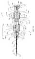
- FIG. 3is a side elevational view of an implant and deployment catheter according to the invention.
- FIG. 4is a segmented view of the assembly shown in FIG. 3 , and shows an enlarged fragmentary view of an implant attachment region of the assembly.
- FIG. 6shows a perspective view of a proximal region of an implant according to the invention.
- FIG. 8Ashows a partially cross-sectioned side view of an implant, in a first configuration during a first mode of use.
- FIG. 8Bshows a similar view as that shown in FIG. 8A , with the implant in a second configuration during a second mode of use.
- FIGS. 9A-Bshow side elevational schematic views of a distal end portion of a delivery assembly coupled to an elongate body, and show the elongate body during two modes of operation, respectively.
- FIG. 9Cshows a side elevational view of a portion of the implant shown in FIG. 9A .
- FIG. 9Gshows a fragmentary schematic view of two interlocking segments according to one specific mode for the elongate body shown in FIGS. 9A-F .
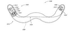
- FIG. 10is a bottom plan view of an alternative medical device including a delivery assembly, comprising a handle assembly and a shaft, and an implant configured for remodeling a mitral valve.
- FIG. 13is an enlarged view of the connection assembly of the medical device of FIG. 12 .
- FIG. 13Ais a cross section view of the male connector of FIG. 13 .
- FIG. 13Cis a partial cross section view taken along view line 13 C- 13 C of FIG. 13 .
- FIG. 13Dis a cross section view taken along view line 13 D- 13 D of FIG. 13 .
- FIG. 16is a cross section view of a handle assembly of the medical device of FIG. 10 .
- FIG. 17is a cross sectional view taken along the view line 17 - 17 of FIG. 16 .
- FIG. 18is a plan view of a portion of the handle assembly of FIG. 16 taken along the line 18 - 18 of FIG. 16 .
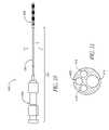
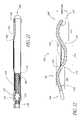
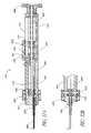
- FIG. 21is a cross sectional view of another implant in accordance with the present invention.
- FIG. 22is a side elevational view of the device of FIG. 21 , in an actuated orientation.
- FIG. 23is a side elevational view of an implant similar to that shown in FIG. 22 , in the implanted configuration, having an expandable basket thereon for securement in a vessel.
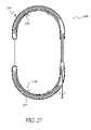
- FIG. 28is an enlarged fragmentary cross sectional view of a portion of the implant illustrated in FIG. 27 .
- FIGS. 30A and Bare schematic views of an alternate implant in accordance with the present invention.
- FIG. 31Ais a side elevational view of an alternative implant in accordance with the present invention.
- FIG. 31Bis a cross-sectional view taken along line 31 B- 31 B of FIG. 31A .
- FIG. 31Cis a plan view of a ratchet strip for use with the implant of FIGS. 31A and 31B .
- FIG. 31Dis a plan view of a disconnect sub-assembly for use with the ratchet strip of FIGS. 31A-C .
- FIG. 31Eis a cross-sectional view taken along line 31 E- 31 E in FIG. 31D .
- FIG. 31Fis a plan view showing the catheter coupling of the implant of FIGS. 31A-B
- FIG. 32Ais a cross-sectional view of a proximal deployment handpiece.
- FIG. 32Bis a partial cross-sectional view of the proximal deployment handpiece of FIG. 32A rotated 90 degrees.
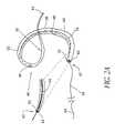
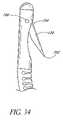
- FIG. 33is a side elevational view of an alternative implant in accordance with the present invention.
- FIG. 34is a side elevational close-up view of the distal end of the implant of FIG. 33 .
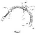
- FIG. 36is a side elevational cutaway view of an alternative implant in accordance with the present invention.
- FIG. 37is a close-up view of the proximal end of the implant of FIG. 36 .
- FIG. 38is a remotely activated implant system in accordance with one aspect of the present invention.
- FIG. 40is an alternative motion module in accordance with one aspect of the present invention.
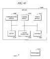
- FIG. 41is an alternate remotely activated implant system in accordance with the present invention.
- FIG. 42is an illustration of implantable components of the remotely activated implant system in accordance with the present invention.
- FIG. 43is an illustration of an alternative embodiment of the remotely activated implant system in accordance with the present invention.
- FIG. 44is a schematic representation of components positioned within an implant, in accordance with one aspect of the present invention.
- FIG. 45is an illustration of components positioned internal to an implant, and distributed throughout the implant, in accordance with another aspect of the present invention.
- FIG. 46is an illustration of another embodiment of the present invention, including a dual coupling for simultaneous interfacing with a housing and a deployment catheter.
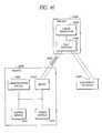
- FIG. 47is an illustration of yet another remotely activated implant system in accordance with the present invention.
- FIG. 48is a flow chart illustrating a method of remote activation of an implant system in accordance with one aspect of the present invention.
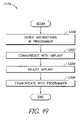
- FIG. 49is a flow chart illustrating a method of remote adjustment in accordance with another aspect of the present invention.
- FIG. 50is a flow chart illustrating yet another method of remote activation of an implant system in accordance with another aspect of the present invention.
- FIG. 51is an illustration of electrical and mechanical components included in one embodiment of the implant system.
- FIG. 52is an illustration of an alternative embodiment of the remotely activated implant system in accordance with the present invention.
- FIG. 53is an illustration of an implant in accordance with another aspect of the present invention.
- FIG. 54is a cross-sectional illustration of an embodiment of a secondary housing implanted within a vessel such as the superior vena cava.
- FIG. 55is an illustration of a secondary housing in accordance with another embodiment of the present invention.
- FIG. 56is an illustration of a secondary housing in accordance with yet another embodiment of the present invention.
- Preferred embodiments of the present inventioninclude a method and apparatus for performing mitral annuloplasty and remodeling of the left ventricle using a device that may be introduced percutaneously, and placed within the coronary venous system of the heart.
- the deviceexerts compressive force on the mitral annulus and left ventricle, reducing the severity of mitral regurgitation and the size of the left ventricular cavity.
- the devicethus enables reduction of the mitral annulus and constraint of the diastolic expansion of the left ventricle yet without the morbidity and other risks associated with open chest surgery. Additional details are disclosed in the parent application Ser. No. 10/066,302, filed on Jan. 30, 2002, the disclosure of which is incorporated in its entirety herein by reference.
- the coronary sinus and veinsprovide an ideal conduit for the positioning of an intravascular prosthesis, or implant, for remodeling the mitral annulus, since they are positioned adjacent the mitral annulus and interventricular septum.
- implantis a broad term, and should not be limited to a permanently introduced structure or device, but could additionally be a temporarily introduced device.
- the coronary sinusis contained within the atrioventricular groove, and is in close proximity to the posterior, lateral and anterior aspects of the mitral annulus.
- the coronary sinus and coronary veinsare cannulated currently during any of a variety of percutaneous transvenous diagnostic and therapeutic procedures. Permanent placement of pacemaker and defibrillator leads within the coronary sinus and veins is both safe and well tolerated.
- the annuloplasty systemconsists of several components. Desirably, there is a delivery system intended to be introduced percutaneously into a central vein such as the internal jugular, subclavian or femoral veins and to cannulate the coronary sinus.
- the implant of the present inventionis deployed from the delivery system, preferably a delivery catheter, into the coronary venous system or into a position within or adjacent the myocardium, to influence the annulus of the mitral valve. Additional tools may be placed through or along the delivery catheter to position the device, apply elements in place, and to control and/or cut tensioning elements (if provided) from the delivery system, as will be discussed in detail below.
- FIG. 1there is illustrated a schematic view of the heart 10 , having a preferred embodiment of a mitral annuloplasty and cardiac reinforcement device 40 positioned therein.
- the heart 10generally comprises a right atrium 12 , in communication with the superior vena cava 14 and inferior vena cava 16 .
- the left ventricle 18is positioned below the left atrial appendage 20 .
- Relevant portions of the coronary vasculatureinclude the coronary sinus 22 , which extends from the ostium 24 to the junction 26 of the coronary sinus and the great cardiac vein 28 .
- There may be anastomotic connections 29 between the great cardiac vein 28 and the middle cardiac vein 30as is well understood in the art.
- a mitral annuloplasty and cardiac reinforcement device 40is illustrated generally in the coronary sinus 22 .
- the device 40extends from a proximal end 42 to a distal end 44 .
- the proximal end 42lies against the posterior aspect of the interatrial septum 46 .
- the midportion 48 of the device 40is positioned within the coronary sinus 22 .
- the transitional section 50 of the device 40lies at the junction 26 of the coronary sinus 22 and the great cardiac vein 28 .
- the distal end 44 of the device 40is lodged in the great cardiac vein 28 .
- the transitional region 50is designed to reside in the proximal portion of the great cardiac vein 28 .
- an anchor 52By deflecting out of a plane defined by the coronary sinus 22 , it serves as an anchor 52 and prevents the device 40 from slipping out of the coronary sinus 22 when tension is applied.
- This embodiment of an anchor 52is, preferably, very flaccid and flexible, thereby minimizing the risk of erosion of the device 40 through the wall of the great cardiac vein or other aspect of the coronary venous system.
- the proximal end 42 of the device 40lies outside the ostium 24 of the coronary sinus 22 and is desirably curved upward so as to anchor against the posterior aspect of the interatrial septum 46 .
- the proximal end 42 of the illustrated device 40is semicircular in shape and elliptical in profile so that no edges will promote erosion of adjacent tissue.
- any of a variety of structuresmay be provided.
- the deployed device 40will contact the wall of the coronary sinus 22 along the inside radius of its arcuate path.
- a tissue contacting surface 54 on the concave side of the deployed device 40may be provided with any of a variety of friction enhancing surface structures, such as a plurality of transverse ridges, teeth or other projections, or modified surface textures to enhance friction.
- tissue engaging or piercing structuressuch as barbs may be provided on the surface 54 to engage the wall of the coronary sinus 22 to resist movement of the device 40 , as will be discussed.
- inventions herein shown and describedare believed to be particularly useful in one aspect specifically because they operate without the need for such aggressive tissue engagement. It will be apparent to one of ordinary skill based upon this disclosure that the present embodiments provide independent device manipulation and shape control that allow for sufficient forces to be applied to the mitral valve without requiring the possibly harmful effects of puncturing and grabbing tissue within the sinus for the remodeling process.
- the independent action of a barbless designallows for adjustment in both the tightening and loosening directions with reduced risk of significant tissue damage or erosion.
- devices 40beneficially maintains its length throughout its modified range of shapes while the sinus and adjacent valve annulus reduce their dimensions under the force of remodeling.
- the specific dimensions, construction details and materials for the mitral annuloplasty and cardiac reinforcement device 40can be varied widely, as will be appreciated by those of skill in the art in view of the disclosure herein. For example, dimensional adjustments may be made to accommodate different anatomical sizes and configurations. Materials and construction details can be varied to accommodate different tensioning mechanisms and other considerations.
- the device 40defines an overall length from proximal end 42 to distal end 44 .
- the lengthis within the range of from about 2 cm to about 10 cm in an embodiment such as that illustrated in FIG. 2 in which the anchor 52 comprises a distal extension of the body 66 for lodging within the great cardiac vein 28 .
- One embodiment of the device 40includes an elongate flexible body 66 about eight centimeters in length.
- the body 66may be elliptical in cross section so that it will bend in a single plane when force is applied to the tensioning element within it, as will be discussed below.
- the device 40tapers and transitions to a round cross-section.
- FIGS. 2A-Bthere is illustrated an embodiment of the device 40 having a forming element 56 , such as a wire, therein.
- Manipulation of the forming element 56allows the device to be moved from a flexible orientation to enable percutaneous insertion into the vascular system and navigation into the coronary sinus ( FIG. 2B ), to an arcuate configuration for compressing at least a portion of the mitral annulus ( FIG. 2A ).
- the device 40may be advanced from the first, flexible configuration to the second, arcuate configuration by either axial proximal retraction or distal advancement of the forming element 56 with respect to the body 66 , depending upon the particular design.
- the device 40comprises an elongate flexible support 58 , extending from a proximal end 42 at least as far as a point of attachment 60 .
- the support 58may be a portion of the body 66 or may be a distinct component as will be discussed.
- the support 58has a fixed length, and is substantially axially non-compressible and non-expandable.
- proximal axial retraction of the forming element 56 relative to the proximal end of the support 58will desirably cause the support 58 to deflect in a first direction, tending to bend the body 66 about an axis transverse to the longitudinal axis of the body 66 .
- This basic steering configurationcan be embodied in many forms, which can be optimized by those of skill in the art to suit a particular construction for the body 66 depending upon the desired dimensions and clinical performance.
- the forming element 56extends from the proximal end 42 through the device 40 to the point of attachment 60 .
- the forming element 56is mechanically coupled, and preferably, directly coupled to the support 58 .
- a proximal extension 64 of the forming element 56extends from the proximal end 42 of the device 40 , such as through an aperture 62 . Proximal retraction of the forming element 56 through the aperture 62 causes the device 40 to bend from an implantation, or delivery orientation, for navigating the coronary vasculature during implantation, to a formed, or remodeling orientation for compression and constraint of the coronary sinus 22 and adjacent structures.
- the device 40preferably provides a compressive force against the mitral annulus as has been discussed. This is desirably accomplished by forming the device into an arcuate configuration. Generally, the best fit curve of constant radius to which the formed device conforms has a radius within the range of from about 1.0 cm to about 2.0 cm.
- the forming elementmay comprise any of a variety of materials and constructions, such as a polymeric or metal wire or strand, a multi-filament braided or woven line, a metal or polymeric ribbon, or other structure capable of retaining the device 40 under tension in the coronary sinus 22 .
- the device 40further comprises a support 58 , which may be the body 66 of the device 40 or a separate element positioned therein.
- support 58may comprise any of a variety of generally axially non-compressible elements such as a metal or polymeric wire or column, ribbon, or “bottomed out” (e.g., fully compressed) spring which facilitates lateral bending but inhibits axial compression upon proximal retraction of forming element 56 .
- a metal ribboncomprising stainless steel, nitinol, or other known materials may be desired in certain embodiments, due to its ability to influence the plane of curvature of the device 40 when in the formed orientation.
- the proximal extension 64 of the forming element 56extends proximally throughout the length of a deployment catheter, to a control or free end which remains outside of the patient during the deployment procedure. Following placement of the device 40 in the coronary sinus, proximal traction on the proximal extension 64 will reconfigure the device 40 into the formed orientation within the coronary sinus, as will be discussed in connection with the method of use of preferred embodiments. After a sufficient tension has been placed on the coronary sinus 22 , the forming element 56 is preferably locked in a fixed axial position with respect to the device 40 , to resist distal movement of the forming element 56 through aperture 62 . Any of a variety of suitable lock arrangements may be provided.
- the lock 70is provided on or near the proximal end 42 , and, in particular, at or about the aperture 62 .
- the lockmay comprise any of a variety of structures, such as a suture knot, locking clamp or ring, an interference fit, ratchet and pawl structures, threaded engagement, an adhesive bond, or a compression fit, as will be apparent to those of skill in the art in view of the disclosure herein.
- the lock 70(on any of the embodiments herein) may be initially disengaged, so that the forming element 56 may be retracted or advanced freely through the aperture 62 while the physician adjusts the tension on the device 40 .
- the lock 70is activated to engage the forming element in a manner which will depend upon the lock design.
- the lock 70may be biased into an engaged configuration, such as with ratchet or cam structures, so that the forming element can only be retracted proximally.
- the lockwill allow the forming element to be released so that the physician can release tension on the device 40 in the event of momentary over tightening.
- the forming element 56 and support 58may be surrounded by a tubular jacket of ePTFE or a polyester fabric such as DACRON, or other material which is wrapped or stitched onto the forming element 56 to produce the final device 40 .
- the subassembly which includes the forming element 56 , and, if present, support 58may be positioned within a suitable length of tubing formed such as by extrusion. The tubing may be drawn down to a reduced diameter at the distal end 44 . Additional post extrusion steps may be used to produce the desired cross-sectional configuration. Manufacturing techniques for the present invention will be apparent to those of skill in the art in view of the disclosure herein.
- the outside surface of the body 66may be provided with any of a variety of coatings, such as poly-paraxylene, sold under the trademark PARALENE, PTFE or others to improve lubricity; heparin or other antithrombogenic agents; elastomers such as silicone, neoprene, latex or others to soften the surface and reduce the risk of trauma to the vascular intima, and the like.
- Adhesion enhancing surfacesmay be provided, such as ePTFE patches or jackets, to promote cellular ingrowth for long term anchoring.
- the body 66may be provided with a guidewire lumen extending axially therethrough, to allow the body 66 to be advanced distally over a guidewire during placement at the treatment site.
- the device 40may be implanted within the coronary sinus 22 either through direct surgical (e.g., thoracotomy, with or without sternotomy) access, such as in combination with another surgical procedure, via port access, or remotely by way of a percutaneous or surgical cut down access to the venous system.
- the device 40is implanted in a transluminal procedure, such as by way of a percutaneous access at one of the internal jugular, subclavian, or femoral veins.
- FIGS. 3-8Billustrate an exemplary device assembly 200 .
- FIG. 3is an overall view of assembly 200 that includes a delivery assembly 210 engaged to a prosthesis, or implant 250 .
- prosthesis 250is adapted to be delivered in a first condition and shape into a vessel at least in part by manipulation of delivery assembly 210 .
- prosthesis 250is adapted to be adjusted to a second condition and shape within the vessel in order to influence an adjacent tissue structure.
- a particularly beneficial mode of such operationplaces the prosthesis 250 within a coronary sinus for the purpose of influencing a mitral valve annulus, more specifically in order to influence the shape of the annulus in order to reduce mitral valve regurgitation.
- FIGS. 4-7show the proximal aspects of device assembly 200 , and in particular various details for delivery assembly 210 that includes an outer member 215 that is preferably tubular with an inner lumen 216 that is preferably sized to house an inner member 225 .
- Inner member 225 in the variation shownis generally tubular and is substantially free to rotate within lumen 216 , preferably by providing rotational force to inner member 225 proximally outside of the patient's body. According to the example shown, this rotational force is applied to inner member 225 via a thumbwheel 205 that is provided on proximal hub assembly 201 coupled to proximal end portion 211 of delivery assembly 210 .
- Thumbwheel 205is rotationally coupled to inner member 225 within hub assembly 201 , which rotational coupling may be achieved according to a number of adaptations as would be apparent to one of ordinary skill.
- Rotation of inner member 225is transmitted into rotation of a rotational coupler 280 that is engaged within a proximal end portion 252 of prosthesis 250 as follows.
- Inner member 225has an aperture 228 on its distal end portion that provides a female counterpart of a mated key interface between the inner member 225 and a male counterpart, desirably provided by a shaped proximal end 281 of a rotational coupler 280 that is also rotationally engaged within a proximal end portion 252 of prosthesis 250 .
- the keyed fitting between inner member 225 and rotational coupler 280allows for transmission of rotational forces to rotational coupler 280 .
- a flexible membersuch as a filament 240 is looped through an aperture 283 through proximal end 281 of rotational coupler 280 with both filament ends 242 and 244 extending proximally through inner member 225 to a location in the proximal end of the catheter.
- the filament 240is generally held in sufficient tension to keep the distal keyed fitting engaged, though it is further contemplated that the mere presence of the filament may provide an interference against uncoupling if there is a sufficiently tight tolerance in the male/female interface of the keyed fitting.
- Rotational coupler 280is rotationally engaged within proximal end portion 252 of prosthesis 250 through a proximal port, or aperture 251 , such that the rotational coupler 280 is adapted to rotate within and relative to the prosthesis 250 .
- This relative rotationis converted to force a deflection of prosthesis 250 into the desired shape of the second configuration in situ as follows.
- the prosthesis 250is preferably held to resist rotation while rotational coupler 280 is rotated within the prosthesis 250 .
- Thismay be achieved simply by frictional forces of surrounding tissue after the prosthesis 250 has been delivered into the desired vessel such as the coronary sinus.
- thismay be achieved by providing a releasable interface such as a friction fit between outer member 215 and proximal end portion 252 of prosthesis 250 wherein the frictional engagement of outer member 215 and prosthesis 250 are held in a relatively fixed position while inner member 225 and rotational coupler 280 are rotated.
- a keyed interfacemay be employed as shown in FIGS.
- a shaped proximal fitting 253 on the proximal end 252 of prosthesis 250is adapted to mate as a male counterpart into a shaped aperture or fitting on the distal end 212 of outer member 215 .
- This keyed interfaceallows for rotational coupling between the members in a similar manner as just described for the inner member 225 and rotational coupler 280 , and may allow for a more releasable coupling with reduced friction upon axial detachment of the members.
- Prosthesis 250includes a generally tubular wall or body 260 that has an inner lumen 262 and extends from the proximal end portion 252 to the distal end portion 254 of prosthesis 250 .
- a nut fitting 263Secured along proximal end portion 252 is a nut fitting 263 that has a grooved inner bore 264 which communicates with inner lumen 262 .
- rotational coupler 280is a screw member with outer helical threads 285 engaged within the mating threads of an inner surface (not shown) of a bore lumen such that a distal portion of screw threads 285 extends distally within lumen 262 and terminates at a second key fitting 287 similar to the shaped proximal end portion 282 and also having an aperture 288 .
- another flexible member or filament 290is looped through aperture 288 such that two arms 292 , 294 extend distally therefrom to an attachment point along distal end portion 254 of prosthesis 250 .
- the forced deflection described immediately abovemay be controlled in a particular plane by providing a composite structure within prosthesis 250 that is engineered to respond, e.g., yield, to these forces in a prescribed way.
- a relatively noncompressible column support or spine member 270is provided within lumen 262 of outer tubular body 260 .
- This spine member 270is more rigid and more resistant to axial forces, especially tensile forces, than the material of outer tubular body 260 alone. Therefore, providing spine member 270 along only one radial position along the circumference of the prosthesis 250 creates a bias on the device 250 to deflect away from the spine 270 toward a more compressive region of the device 250 .
- Such composite designmay further include a laminate structure a composite structure—such as an imbedded wire reinforced wall structure, or may be achieved by engineering material variations in the device, such as for example by thinning, thickening, hardening, or softening the material at one location along the outer tubular body 260 relative to another region to urge the body 260 to deflect at a desired location.
- a laminate structuresuch as an imbedded wire reinforced wall structure
- engineering material variations in the devicesuch as for example by thinning, thickening, hardening, or softening the material at one location along the outer tubular body 260 relative to another region to urge the body 260 to deflect at a desired location.
- deflection according to the present embodimentmay be adjusted according to a healthcare provider's desires, and is adjustable in either direction—by either tightening the radius of curvature R or opening it. See FIG. 8B .
- the adjustability of and choice between tightening and loosening of the deflectiondepends upon the direction and extent of rotation placed upon the rotational force transmission system.
- the prosthesis 250may be detached from the delivery assembly 210 by severing the torque or rotational force transmission system at the keyed fitting between the inner member 225 and the rotational coupler 280 . This is accomplished by first releasing at least one arm 242 , 244 of the proximal filament 240 while withdrawing the other arm, thereby threading the filament 240 through aperture 283 (as shown in bold arrows in FIG. 8B ) until it is unthreaded completely from the aperture 283 . This allows inner member 225 to be withdrawn proximally from rotational coupler 280 to detach and thereby implant the prosthesis 250 .
- the prosthesismay be held in its therapeutic condition for a temporary period of time (which may nevertheless be prolonged during a hospital stay), during which time mitral valve regurgitation may be minimized, such as for example for the purpose of bridging the patient in a temporarily improved condition until other treatments may be performed, e.g. annuloplasty, valve surgery, heart transplant, etc.
- mitral valve regurgitationmay be minimized, such as for example for the purpose of bridging the patient in a temporarily improved condition until other treatments may be performed, e.g. annuloplasty, valve surgery, heart transplant, etc.
- the deflected, contracted prosthesismay be adjusted back open from its cinched position around the valve, and then withdrawn without implantation by withdrawing the entire system, delivery assembly still engaged to the prosthesis.
- such a temporary prosthesismay be modified to remove the detachment mechanisms herein described, which may provide for a simpler and lower cost device.
- Device assembly 200is also shown in FIGS. 3 and 8 A-B to include a distal guidewire tracking member with a guidewire lumen 265 which is adapted to slideably engage a guidewire 230 in order to be placed in a percutaneous transluminal procedure into the desired vessel location, such as within the coronary sinus 22 .
- the particular guidewire lumen shownis integral within the distal aspects of prosthesis 250 as a “rapid exchange” or “monorail” design that allows for relatively independent movement of the guidewire and catheter in vivo. Moreover, this design removes the need for the guidewire to ride coaxial through the entire device assembly 200 , as would be the case for example in an “over the wire” type system.
- the type shownbeneficially allows for detachable engagement of prosthesis 250 , which is preferably achieved after withdrawing the optional guidewire 230 from the distal lumen 265 .
- the physicianpreferably monitors the degree of regurgitation during the step of tightening the implant.
- regurgitationis preferably reduced to something less than moderate (less than 2+). In any event, at least a one grade reduction is preferably achieved.
- reconfiguration of the implant 250is desirably not accomplished to an extent sufficient to produce mitral stenosis, or any flow limitation of hemodynamic significance.
- the method of implantationpreferably further comprises the steps of monitoring the degree of mitral regurgitation during, and preferably also before and following the implantation and/or reconfiguration steps.
- the degree of mitral regurgitationmay be monitored such as by transesophageal echo cardiography, intracardiac echo cardiography, fluoroscopy using radiocontrast in the left ventricle (LVgram), or left atrial or pulmonary capillary wedge pressure tracings, as are understood in the art, during the incremental restriction of the mitral annulus and/or left ventricle step.
- the methodmay additionally comprise the step of measuring the coronary sinus 22 and/or other coronary vein, and selecting an appropriately sized implant 250 from an array of implants of varying sizes. Such parameters may include diameter, length, or radius of curvature of the arc of the sinus.
- the appropriately sized implant 250is thereafter positioned within the target vein.
- the implant 250is thus preferably provided in a graduated array of sizes, so that the optimal size can be selected for each patient.
- the size of the coronary sinus 22 or other veincan be measured using any of a variety of techniques, such as echo cardiogram, MRI, CT Scan, or angiography as is understood in the art.
- measuring a parameter of the coronary sinus 22generally provides indicia of certain parameters of the mitral valve and its annulus, such as for example mitral valve diameter, in which case either the coronary sinus parameter or the mitral valve parameter may provide the requisite information for choosing an appropriately dimensioned device 250 from the kit.
- mitral valve parametersmay further be measured directly, such as by various of the methods just described, in order to generate the values used for choosing the appropriate device 250 .
- a parameter for an anatomical featureis measured as herein described, its value is generally estimated according to the accuracy of the respective measuring tool—it is contemplated that persons without specialized medical skills or training can choose the appropriate medical device 250 from the kit once armed with this estimated value.
- packaging for each device 250 of the kitmay indicate the respective dimensions that are unique to that device 250 with respect to other devices of the kit, and the estimated value of the measured anatomical parameter may simply be compared.
- various of the embodiments herein describedare adapted to accomplish manipulation of the coronary sinus 22 for mitral annulus reduction without substantially altering the length of the device 250 within the sinus 22 .
- Thismay provide a benefit by increasing the useful purchase of the device 250 along the coronary sinus 22 and circumferentially around the mitral annulus as the sinus length and/or annulus diameter may be reduced during remodeling from the radial deflection of the prosthetic device 250 .
- Thismay also mean that the dimension of the device 250 in a kit of devices may not directly correspond to the estimated value of the anatomical parameter that is measured.
- the compared value of the measured device parametermay be shorter than an estimated coronary sinus 22 length due to a possible shortening of the sinus 22 during device 250 treatment.
- the anatomical parametermay be estimated from an initial value based upon an anticipated or desired final result from treatment and such procedurally related value be used for choosing the appropriate device (e.g. comparing an estimated final length of the sinus or mitral valve diameter with a known dimension of the device in the remodeling configuration when used in situ).
- the implant 250is preferably combined with an appropriate drug therapy for treating congestive heart failure. Residual regurgitation and other hemodynamic functions are preferably measured following implantation of the implant of the present invention. Heart medications are preferably adjusted to take into account the reduction in regurgitation and/or reduction in left ventricle volume in formulating an ongoing drug therapy for the patient.
- the present inventioncontemplates temporary use in the sinus 22 for mitral valve remodeling as a bridging regime in combination with other permanent treatments such as more conventional annuloplasty or valve replacement via surgery.
- Such combined systems of devices 250 and respective methods of usewhich may further be combined with the pharmaceutical drug regimes, provide an overall treatment regime that can provide a highly beneficial result for management of patients with harmful mitral valve regurgitation.
- any of the embodiments discussed hereinmay additionally be provided with one or more externally facing electrically conductive axially extending strips or annular bands, to enable the device 40 to function additionally as a cardiac pacing or other diagnostic or therapeutic cardiac electrode.
- the electrically conductive band or bandsare placed in electrical communication with a pacing source or diagnostic instrument by way of one or more electrical conductors extending away from the device 40 .
- the conductorsmay be electrically connected to any of a wide variety of electronic cardiac rhythm management devices, which are well known in the art.
- the elongate body 320is adapted to be adjusted from the first implantation (flexible) configuration to a second (relatively rigid) remodeling configuration that has a shape that is adapted to remodel the mitral valve annulus.
- this shapeis generally adapted to provide an external force onto the annulus in order to reduce its diameter along at least one transverse axis, such as according to the arcuate shape shown that at least in part grips down onto a portion of the circumference of the valve to provide a diameter reducing force.
- the arcuate shapemay take different forms in terms of degree, and in a further highly beneficial application is controllable and selectable between various or through a continuous range of degrees.
- controllability according to the embodiment shownis also selective between intermediate deflectable portions 360 , 370 , 380 , as is shown in FIG. 9B and will be further developed below.
- Elongate body 320is constructed from tubular wall 325 that extends continuously along the length of the deflectable portions 360 , 370 , 380 of the elongate body 320 .
- An array or plurality of distinct, discontinuous slots or voids 330are formed within the wall 325 , each void 330 having an elongated shape that is transverse to the longitudinal axis.
- Voids 330permit axial shortening of one side of the tubular wall 325 , enabling the curvature illustrated in FIG. 9B .
- transverse voids 330have a central groove-shaped region with two adjoining portions 332 , 334 that converge at an apex 333 along the longitudinal axis.
- a shaped void 330is defined at least in part by two opposing complementary shaped surfaces of two adjacent, longitudinally opposing portions 340 , 350 of the wall of the elongate body 320 .
- One of these portions 340desirably assumes a convex shape in an axial, distal direction
- the other portion 350is desirably concave in an axial, proximal direction around the apex 333 .
- These shaped surfaces 340 , 350are preferably in a nested configuration with the convex portion 340 positioned within the concave portion 350 .
- lateral (rotational) movement of one of the adjacent wall portions 340 , 350 relative to the other portion 340 , 350is substantially prevented by a mechanical interference with the other adjacent portion 340 , 350 .
- the relative nesting of adjacent portions 340 , 350 of the elongate body 320provides a mechanical interference to radial deflection along a first plane and substantially isolates deflection of the elongate body 320 along a second plane upon application of axial bending forces.
- FIG. 9Dshows grooved voids 330 in plan view for the purpose of simplifying the illustration for better understanding.
- these transverse voids 330(and the generally the entire V-shaped portion herein described in detail) span across at least about 180 degrees of the circumference of the elongate body 320 .
- the transverse voids 330span across more than about 300 degrees of the circumference of the elongate body 320 , and still more preferably the voids span across between about 300 degrees and about 315 degrees of the circumference.
- an integral and continuous backbone or spine 327is formed along wall 325 that runs axially along the length of the elongate body 320 .
- This overall arrangement of voids 330 and spine 327has been observed to provide a desirable combination of bendability, due to the voided pattern, and axial integrity, due to the remaining wall structure.
- the elongate body 320 of the implant 300 shown in FIGS. 9A-Fgenerally has three deflectable portions 360 , 370 , 380 , and one non-deflectable portion 310 along the longitudinal axis.
- Each deflectable portion 360 , 370 , 380has a group of voids 330 as just described in order to be individually deflectable between the first and second configurations with an applied force from outside of the patient's body while the elongate body 320 is positioned within the coronary sinus.
- three forming elements 365 , 375 , 385may be coupled to the three deflectable portions 360 , 370 , 380 , respectively, in order to apply a deflection force to that portion to reshape that portion between the first and second configurations.
- Each forming element 365 , 375 , 385is preferably adapted to extend externally from the patient's body when the elongate body 320 is positioned within the coronary sinus in order to be manually manipulated to apply the deflection force to the respectively coupled deflectable portion 360 , 370 , 380 . Deflection of each of these portions combined provides for the overall shape for the elongate body 320 in the second configuration.
- Forming elements 365 , 375 , 385are attached to elongate body 320 at unique, longitudinally spaced points of attachment 361 , 371 , 381 , respectively, that are each at or distal to the distal end of each respectively coupled deflectable portion 360 , 370 , 380 .
- each point of attachment 361 , 371 , 381has two axially spaced apertures, which are shown as proximal and distal apertures 362 , 363 for point of attachment 361 , proximal and distal apertures 372 , 373 for attachment point 371 , and proximal and distal apertures 382 , 383 for point of attachment 381 .
- proximal and distal apertures 362 , 363for point of attachment 361
- proximal and distal apertures 372 , 373for attachment point 371
- proximal and distal apertures 382 , 383for point of attachment 381 .
- a shaped distal end 377 for forming element 375is sized to be seated within distal aperture 373 where it is secured by a securing agent 374 which may be an adhesive, melt bond, or solder, for example. Any or all of the respective forming elements 365 , 375 , 385 may also be welded through the apertures to the wall.
- Forming element 375extends proximally from distal aperture 373 and is further secured to wall 325 by additional securing agent 374 introduced through proximal aperture 372 .
- the securing agent 374may be applied in one operation from outside in through both apertures 372 , 373 .
- distal end 377may also be shaped to provide a mechanical securement means for attachment during proximal axial forces, such as is shown in phantom in FIG. 9F .
- the apertures for this attachment embodimentare generally between about 0.020 inches and about 0.022 inches in diameter with similar longitudinal spacing, and the distal end for the seated forming elements are between about 0.012 and about 0.014 inches in diameter.
- wall 325is generally constructed from a tubular, stainless steel wall or hypotube with a plurality of grooved voids 330 formed therein according to a pattern similar to that shown and described by reference to FIG. 9D or elsewhere herein.
- the respective forming elementsare soldered to the respective attachment points using gold/tin solder.
- grooves such as shown and described by reference to FIG. 9Dwere formed in the underlying stainless tube by laser cutting, though other well known techniques such as hand grinding, mechanical cutting, photo-lithography, etc. may alternatively be used.
- the applied force from the forming elements 365 , 375 , 385are generally an axial force between the attachment points 361 , 371 , 381 to the elongate body 320 and a proximal location (not shown) along the elongate body 320 that is proximal to that deflectable portion. According to the specific embodiments shown this force is generally between the attachment points 361 , 371 , 381 and the proximal end portion of the elongate body 320 .
- the elongate body 320may generally be held during forced deflection by means of a holding device (not shown) in order to substantially fix the proximal end portion of the elongate body 320 relative to the deflectable portion so that the axial force may be applied between those portions in situ. While the proximal manipulation of the forming elements 320 in order to apply the deflection force to the deflectable portions 360 , 370 , 380 may be axial as just described, it may in another regard be rotational.
- Each deflectable portion 360 , 370 , 380is substantially axially rigid and non-compressible relative to the longitudinal axis L, and therefore the overall axial length of elongate body 320 remains substantially constant between the first and second configurations.
- each deflectable portionis relatively flexible along a radial axis transverse to the longitudinal axis such that the deflectable portion is adapted to bend radially upon application of an axial force between a distal location on the elongate body at or distal to a distal end of the deflectable portion and a proximal location along the elongate body 320 proximal to that deflectable portion.
- the elongate body 320may be generally axially non-compressible or non-expandable between each deflectable portion 360 , 370 , 380 and the proximal end portion of the elongate body 320 , such that each deflectable portion 360 , 370 , 380 is adapted to bend radially upon application of a compressive or tensile axial force, respectively, on the elongate body 320 between the distal location and a proximal location that is at the proximal end portion of the elongate body 320 .
- This motionprovides an interference between teeth 344 , 354 that deflects portion 340 until further motion toward portion 350 clears tooth 354 and recovery locks tooth 344 behind 354 .
- This interactive motion of adjacent portions in voided regionsis further represented by bold arrows in FIG. 9G .
- FIG. 10illustrates an additional construction of a medical device 400 adapted to position an implant 402 , or prosthesis, into the coronary sinus or other treatment site.
- medial device 400includes a handle assembly 404 at a proximal end, while the implant 402 is located at a distal end.
- the handle assembly 404 and implant 402are connected by an elongate, flexible catheter body 406 .
- the body 406is or includes an extrusion of a material having sufficient column strength, that is, it resists compression in an axial direction, while permitting the body 406 to bend in a radial direction.
- the body 406has an outside diameter of approximately 0.094 inches.
- a plurality of lumens or passagesextend in an axial direction along the length of the catheter body 406 .
- the illustrated extrusionincludes three small lumen 408 , 410 , 412 and one larger lumen 414 .
- the small lumen 408 , 410 , 412may be disposed substantially within one half of the circular cross section of the body 406 and each has an inside diameter of approximately 0.024 inches.
- the larger lumen 414is desirably positioned substantially within a half of the circular cross section of the body 406 opposite the small lumen 408 , 410 , 412 and may have a diameter of approximately 0.044 inches.
- FIG. 13is an enlarged view of a portion of FIG. 12 illustrating the releasable connection between the delivery assembly 401 and the implant 402 .
- the implant 402is removably connected to the delivery assembly 401 such that the delivery assembly 401 and implant 402 may be disconnected once the implant 402 has been properly positioned and tensioned within the coronary sinus or other body lumen or hollow organ.
- the implantmay be constructed from a similar material as those embodiments described above, such as a variety of stainless steels, Nitinol or other known materials suitable for implantation.
- An atraumatic distal tip 418is provided on the distal end of the body portion 416 .
- a leading end of the tip 418may be rounded such that the atraumatic tip 418 will not cause significant tissue damage as it is advanced through the vasculature of the patient.
- a nut 422 or other structure having a threaded aperture thereinis provided at the proximal end of the body portion 416 .
- the nut 422is axially and rotationally fixed relative to the body portion 416 .
- the outer edge of the nut 422is circular with flat 464 on one side to provide keyway 481 for pullwire 458 and is sized to fit within the body portion 416 .
- Nut 422is thermally welded to body portion 416 and is provided with keyway 481 .
- other suitable arrangements for preventing relative rotation between the nut 422 and body 416may be used, such as other mechanical interference arrangements, fasteners, solder or adhesives, for example.
- the implant 402additionally includes a screw 428 having a shaft portion 430 and a head portion 432 .
- the shaft portion 430includes external threads which mate with internal threads on the nut 422 .
- rotation of the screw 428 relative to the body portion 416results in the screw 428 translating axially with respect the body portion 416 .
- This relative movementmay be utilized to move the body portion 416 of the implant 402 from an implantation configuration to a remodeling configuration through any suitable construction, such as through the use of a pull wire or other forming element as is described above, for example.
- the head portion 432 of the screw 428includes a rotational coupling such as a cavity 434 extending axially from a proximal end of head portion 432 .
- the cavity 434is shaped to receive a control component of the medical device 400 such as driver 436 .
- the cavity 434is hex shaped and sized to receive a hex-shaped distal end portion 438 of the driver 436 ( FIG. 14 ).
- a transition between the first portion 448 and the second portion 450defines a shoulder surface 452 which extends generally transverse to the longitudinal axis of the male connector 440 .
- the first portion 448 of the passage 446is preferably sized and shaped to receive the head portion 432 of the screw 428 . Desirably, the head portion 432 of the screw 428 abuts the shoulder 452 of the passage 446 .
- An annular collar 454secures the head portion 432 of the screw 428 within the passage 446 .
- the outer diameter of the collar 454is approximately the same as the outer diameter of the head portion 444 of the male connector 440 .
- the collar 454includes an inner flange portion 456 which is sized and shaped to fit within the first portion 448 of the passage 446 of the male connector 440 in a press fit configuration.
- the implant 402desirably includes a wire 458 which is operational for moving the implant 402 from a first, delivery configuration to a second, remodeling configuration.
- the wire 458is desirably anchored to a distal end of the implant 402 by thermal welding or any of the methods described above, or any other suitable method as may be determined by one of skill in the art.
- the proximal end of the wire 458is anchored to the male connector 440 and collar 454 and, preferably, is thermally welded or otherwise bonded to the male connector 440 and collar 454 .
- other suitable methods of attachmentmay also be used, such as an adhesive or mechanical fastener, for instance.
- the male connector 440 , and collar 454have slots 460 and 462 to fit the proximal end of pull wire 458 to allow the wire 458 to lay flat and not increase the outside diameter of collar 454 or connector 440 .
- Nut 422includes flat 464 on one side which is sized and shaped to permit clearance for the wire to pass therethrough.
- the delivery assembly 401is preferably capable of being releasably coupled to the implant 402 .
- a female connector 466is desirably coupled, such as by thermal welding, to the connector wire 487 at the distal end of the shaft 406 .
- the female connector 466is preferably hollow and substantially cylindrical in shape.
- the distal end of the female connector 466includes a plurality of prongs, or finger portions 468 , which are able to flex radially outward to permit the female connector 466 to engage the shaft portion 442 of the male connector 440 .
- the resiliency of the material from which the female connector 466 is constructedenables the female connector 466 to firmly grip the male connector 440 .
- an inner surface of the finger portions 468defines an annular projection 470 which corresponds with an annular groove 472 of the male connector 440 .
- the annular projection 470desirably rests in the annular groove 472 to assist and inhibiting undesired relative axial movement between the delivery assembly 401 and the implant 402 .
- the delivery assembly 401additionally includes a cover 474 that is coupled at the distal end of the shaft 406 .
- the cover 474is axially movable from a first position in which the finger portions 468 of the female connector 466 are uncovered to a second position where the cover 474 overlaps at least a substantial portion of the finger portions 468 . In its second position, the cover 474 inhibits undesired flexing of the finger portions 468 to assist in maintaining a connection between the female connector 466 and the male connector 440 .
- one of finger portions 468is removed or omitted from female connector 466 to create space or keyway 483 that fits into key 485 that is thermally welded to shaft portion 442 of male connector 440 .
- FIG. 14is an enlarged view of the driver 436 apart from the medical device 400 .
- the driver 436is desirably an elongate shaft and extends from a proximal end 480 to a distal end 482 .
- the driver 436may be constructed from a NiTi material, however, other suitable materials may also be used.
- the proximal end 480 of the driver 436is desirably coupled for rotation with respect to the handle assembly 404 , which will be described in greater detail below.
- the distal end 482is preferably non circular such as hex-shaped in cross-section and is sized to engage the corresponding hex-shaped cavity 434 of the screw 428 .
- rotation of the driver 436results in corresponding rotation of the screw 428 .
- Other suitable arrangements to permit rotational coupling of the driver 436 and screw 428may also be used, such as using complementary polygonal or other non round-cross-sectional shapes for the mating components.
- the driver 436may include a shoulder 484 disposed on a proximal side of the hex-shaped distal end 482 .
- the diameter of the shoulder 484is larger than a width W ( FIG. 15 ) of the hex-shaped distal end 482 .
- the diameter of the shoulder 484is approximately 0.032-0.040 inches and the width W is approximately 0.027 inches.
- the shoulder 484effectively functions as a stop when the hex-shaped distal end 482 of the driver is inserted into the cavity 434 of the screw 428 .
- the shoulder 484 and the cavity 434desirably include complementary chamfers 486 , 488 , respectively, to permit easier entry of the hex-shaped distal end 482 into the cavity 434 .
- the illustrated driver 436may include one or more reduced-diameter portions 490 on a proximal side of the shoulder 484 .
- the diameter of portion 490may be smaller than both the width of the shoulder 484 and a diameter of a main portion 492 of the driver 436 , which desirably extends from the proximal end of distal portion 490 to the proximal end 480 .
- the main portion 492 of the driver 436has a diameter of approximately 0.04 inches.
- the reduced-diameter portion 490may have a length of approximately 0.5 inches or more and a diameter of approximately 0.027 inches. However, other suitable dimensions may also be employed.
- each of the transition between the reduced-diameter portion 490 and the main portion 492 of the driver 436 and the transition between the reduced-diameter portion 490 and the shoulder 484define a chamfer 494 , 495 , respectively to advantageously reduce stress concentrations.
- FIG. 16is an enlarged cross-section of the handle assembly 404 , which is primarily comprised of a proximal handle 500 and a distal handle 502 .
- the distal handle 502is configured to be held stationary during use of the medical device 400 and the proximal handle 500 is configured to be rotatable with respect to the distal handle 502 , thus rotating the driver 436 to selectively move the implant 402 between a delivery position and a remodeling position.
- the distal handle 502is generally cylindrical in shape and defines an internal cavity 504 .
- a threaded aperture 506extends from the cavity 504 through the distal end of the distal handle 502 and is substantially concentric with a longitudinal axis of the handle assembly 404 .
- a proximal connector 508is desirably retained by a threaded connection with the threaded aperture 506 and extends axially from a distal end of the distal handle 502 .
- the distal handle 502additionally includes a threaded aperture 510 situated substantially transverse to the longitudinal axis and intersecting the threaded aperture 506 .
- a set screwis advantageously in threaded connection with the threaded aperture 506 and may be tightened against the proximal connector 508 to inhibit undesired axial movement of the proximal connector 508 with respect to the distal handle 502 .
- the proximal connector 508includes a central aperture 514 passing axially therethrough.
- the central aperture 514is desirably substantially concentric with the longitudinal axis of the handle assembly 404 and receives the catheter shaft 406 in a fixed axial position with respect to the distal handle 502 .
- the shaft 406may be fixed to the proximal connector 508 in any suitable manner, such as by adhesives or thermal welding, for example.
- the cavity 504opens through the proximal end of the distal handle 502 to receive a handle connector 516 , preferably through a threaded connection therebetween.
- a set screw arrangement 517is desirably provided to inhibit undesired movement of the handle connector 516 .
- the handle connector 516is configured to connect the proximal handle 500 and the distal handle 502 , while allowing relative rotation therebetween.
- the handle connector 516desirably includes a shaft portion 518 extending proximally away from the distal handle 502 .
- a cylindrical passage 520extends axially through the proximal handle 500 and is sized to be rotatably mounted on the shaft portion 518 of the handle connector 516 .
- the proximal handle 500includes a handle release assembly 522 that permits releasable engagement to the distal handle 502 .
- the release assemblydesirably comprises an annular release collar 524 surrounding the proximal handle 500 .
- the release collar 524is sized to allow axial movement with respect to the proximal handle 500 .
- a plurality of wire retainers 526(two shown) releasably engage the shaft portion 518 of the handle connector 516 to selectively secure the proximal handle 500 in a fixed axial position with respect to the distal handle 502 .
- Each of the wire retainers 526include a short leg 527 , which is circular in cross-section and terminates in a ball end 528 , and a long leg 529 , which is preferably rectangular in cross-section. Desirably, the short leg 527 and the long leg 529 define an angle of approximately 75° between them when the wire retainer 526 is in a relaxed position.
- each wire retainer 526is constructed from a variety of stainless steel and a total of two, or four, or more wire retainers 526 are employed.
- the long leg 529 of the retainer 526is held between an outer surface of the proximal handle 500 and an inner surface of the release collar 524 and, preferably, within a groove 530 defined by the proximal handle 500 .
- a plurality of apertures 532extend radially through the proximal handle 500 near its proximal end.
- the outer surface of the proximal handle 500defines a shoulder 534 between the grooves 530 and the apertures 532 .
- the shoulder 534mechanically deflects the wire retainer 526 , when secured by the release collar 524 , such that the angle between the short leg 527 and long leg 529 is increased from the relaxed position of the wire retainer 526 .
- the inner surface of the release collar 524defines an annular groove 536 , which desirably straddles the shoulder 534 , at least when the release collar 524 is in a relaxed position.
- the short leg 527 of the wire retainer 526extends through the aperture 532 .
- the groove 536preferably engages a bend 538 defined by the transition between the short leg 527 and the long leg 529 of the wire retainer 526 to hold the ball end 528 within an annular groove 540 defined by the shaft portion 518 of the handle connector 516 .
- the release collar 524is in a first, or engaged position such that the ball end 528 is held within the annular groove 540 to inhibit removal of the proximal handle 500 from the distal handle 502 .
- the release collar 524is movable toward the proximal end of the proximal handle 500 into a second, or release position to selectively permit the proximal handle 500 to be removed from the distal handle 502 .
- an edge of the groove 536engages the wire retainer 526 to deflect the short leg 527 and move the ball end 528 out of the groove 540 of the handle connector 516 , thereby releasing the proximal handle 500 from the distal handle 502 .
- a driver holder 525is positioned within the proximal end of the passage 520 to fix the driver 436 for rotation with the proximal handle 500 .
- the driver holder 525is fixed for rotation with the proximal handle 500 , preferably by having a flat 531 which is engaged by a flat portion 539 of the proximal end of the passage 520 ( FIG. 17 ).
- a set screw arrangementsimilar to those described above, may be used to secure the driver holder 525 axially with respect to the proximal handle 500 .
- a pair of set screws 535 , 537secure the driver 436 axially and rotationally with respect to the proximal handle 500 .
- rotation of the proximal handle 500results in rotation of the driver 436 .
- an end cap 541is press fit over the proximal end of the proximal handle 500 to further secure the driver holder 525 .
- the end cap 541may include an aperture 540 A extending axially therethrough. Desirably, the aperture 540 A is substantially aligned with the driver 436 .
- the distal handle 502includes a detach arrangement 542 which allows the delivery assembly 401 to be detached from the implant 402 once it has been properly positioned and moved from its delivery position into its remodeling position.
- the detach arrangement 542includes an annular detach collar 544 surrounding the distal handle 502 .
- the detach collar 544is desirably concentric with the distal handle 502 and capable of sliding axially thereon.
- a handle pin 546is positioned concentrically within the cavity 504 of the distal handle 502 .
- a fastenersuch as a screw 548 , passes through a slot 550 in the distal handle 502 to connect the handle pin 546 to the detach collar 544 .
- external threads of the fastener 548mate with internal threads of apertures 552 , 554 of the detach collar 544 and handle pin 546 , respectively, to provide a secure connection therebetween.
- the handle pin 546is desirably substantially cylindrical in shape and defines an internal cavity 557 extending from an open proximal end to a closed distal end of the handle pin 546 .
- the closed distal end of the handle pin 546includes a pair of apertures 558 , 560 extending axially therethrough, opening into the cavity 557 .
- the aperture 558is sized and positioned to permit the driver 436 to pass there through.
- the aperture 560is sized to receive a proximal end of a detach wire 562 .
- the detach wire 562extends from the handle pin 546 to the cover 474 ( FIG. 13 ) through one of the apertures 408 , 410 , 412 of the shaft 406 .
- the detach wire 562is secured to the cover 474 by any suitable method, such as thermal welding, adhesives, or mechanical fasteners, for example.
- a set screw arrangement 564is utilized to secure the detach wire 562 within the aperture 560 for axial movement with the handle pin 546 .
- the detach wire 562pulls the cover 474 to uncover the finger portions 468 of the female connector 466 .
- the female connector 466is able to be disconnected from the male connector 440 and, thus, the delivery assembly 401 is able to be disconnected from the implant 402 , as described above.
- the handle assembly 404also desirably includes a detach collar lock arrangement 566 to substantially prevent undesired movement of the detach collar 544 .
- the lock arrangement 566preferably includes a threaded aperture 568 passing radially through the distal handle 502 .
- a lock screw 570is provided for threaded engagement with the threaded aperture 568 .
- the lock screw 570includes a head portion 572 , which interferes with movement of the detach collar 544 toward a proximal end of the handle assembly 404 when the lock screw 570 is screwed substantially fully into the aperture 568 .
- the lock screw 570may be backed partially, or fully, out of the aperture 568 to permit desired movement of the detach collar 544 toward the proximal end of the handle assembly 404 .
- the lock screw 570is positioned to prevent undesired movement of the detach collar 544 , which could result in premature detachment of the delivery assembly 401 from the implant 402 .
- the proximal handle 500is rotated with respect to the distal handle 502 to cause rotation of the driver 436 .
- Rotation of the driver 436results in corresponding rotation of the screw 426 which, in turn, causes the implant 402 to move from a delivery configuration to a remodeling configuration, as described in detail above.
- the direction of rotation of the proximal handle 500will vary depending on the orientation of the threaded connection between the screw 428 and the nut 422 . However, if a right hand thread orientation is used, the proximal handle 500 will be rotated counter-clockwise to move the implant 402 from a delivery configuration to a remodeling configuration.
- the lock screw 570is backed off from its locked position to permit movement of the detach collar 544 .
- the detach collar 544may then be moved toward the proximal end of the handle assembly 404 , thereby retracting the cover 474 and exposing the finger portions 468 of the female connector 466 .
- the handle assembly 404may then be pulled with a sufficient force to cause the finger portions 468 of the female connector 466 to deflect radially outwardly such that the female connector 466 may be disconnected from the male connector 440 , thus disconnecting the delivery assembly 401 from the implant 402 .
- the delivery assembly 401is then removed from the patient, leaving the implant 402 in place.
- the proximal hand pieceis provided with a tensioning control, for tightening and untightening the implant, and a release actuator for deploying the implant from the deployment catheter.
- the tensioning controlmay take any of a variety of forms, such as rotatable knobs or wheels, slidable levers, switches, buttons, knobs or other electrical control for controlling a motor drive on the rotatable driver, or others as will be apparent in view of the disclosure herein.
- the release actuatormay take any of a variety of forms, depending upon the construction of the release mechanism.
- any of a variety of axially movable sliders, switches, levers, or rotatable collars, wheels or knobsmay be utilized to control the release actuator.
- any of a variety of locksmay be provided, to prevent premature release of the implant.
- proximal controlmay be provided with any of a variety of auxiliary ports, such as a proximal guide wire port in an over the wire construction, and infusion ports for the infusion of medications, contrast media or other materials depending upon the intended functionality of the device.
- auxiliary portssuch as a proximal guide wire port in an over the wire construction, and infusion ports for the infusion of medications, contrast media or other materials depending upon the intended functionality of the device.
- FIGS. 19 and 20illustrate the slot pattern on an alternative implant 600 , similar to those described above, incorporating a plurality of voids 602 to influence the movement of the implant 600 from a delivery configuration to a remodeling configuration.
- FIG. 19illustrates a plan view of a preferred void 602 arrangement, wherein 57 individual voids 602 are provided.
- a first side of the implantis generally non-compressible, such as is achieved by the use of a tubular wall.
- the first side of the implantis radially opposite a second side of the implant, which is provided with the plurality of voids 602 .
- the voidspermit the second side of the implant to be axially expanded or contracted, thereby curving the implant as will be apparent to those of skill in the art.
- voids 602will influence the bending characteristics of the implant.
- voids which are transverse to the longitudinal axis of the implantcan assist in plane bending of the implant.
- at least about 10 and often at least about 20 voidsare provided.
- Thirty or forty or more voidsmay also be provided, depending upon the desired finished curvature of the implanted device as well as the dimensions of the voids and intervening solid wall material.
- FIG. 20is an enlarged view of a series of adjacent voids 602 .
- a plurality of voids 602are arranged axially along the implant 600 and are positioned substantially transverse to the longitudinal axis of the implant 600 .
- the voids 602extend around at least about 180° of the circumference of the implant 600 and, preferably, around at least approximately 300° of the circumference.
- the voids 602extend around between approximately 300° and 315° of the circumference of the implant 600 .
- the tubular body of the implantmay comprise a spring coil in which adjacent windings are slightly spaced apart.
- Axial column strength on the first side of the implantis provided by an axially extending support such as a flexible ribbon or core wire which may be soldered or otherwise attached to the spring coil to inhibit axial compression along the side which carries the support.
- the opposing side of the coilmay be compressed or expanded, to impart a curve.
- the coilmay be provided with an outer polymeric sleeve.
- both ends of each void 602terminate in a curved void portion such as circular void end portion 603 .
- the end portions 603 of the void 602reduce stress concentrations at the ends of the voids 602 that result from bending of the implant 600 from a delivery configuration to a remodeling configuration.
- the end portions 603have a diameter of approximately 0.018 inches and a circumferential distance between the centers of the two opposing circular portions 603 of a single void 602 is approximately 0.068 inches. This feature decreases the likelihood of cracks originating in the material of the implant 600 at the ends of the voids 602 .
- Each void 602is defined as a space between two opposing edge surfaces 604 , 606 of the body of the implant 600 .
- Surface 604includes an axially extending projection such as substantially “U-shaped” projection 608 positioned within a complementary, substantially “U-shaped” recess 610 of surface 606 .
- Alternative complementary configurationssuch as a chevron may also be used.
- An axis A V of both the projection 608 and the complementary recess 610is substantially parallel to the longitudinal axis of the implant 402 .
- An axial distance between the substantially transverse edges 604 , 606defines a width W V of the void 602 .
- the W V of the void 602may be varied, depending upon the desired performance. In general, widths within the range of from about 0.010 to about 0.040 inches are often used. In the illustrated embodiment, the width W V is approximately 0.012 inches. Desirably, a distance between at least a portion of both sides of the projection 608 and recess 610 is less than the void width W V and defines a pair of interference portions 612 between the surface 604 and the surface 606 .
- the interference portions 612inhibit the implant 600 from moving out of a plane defined by the longitudinal axis of the implant 600 as it moves from a delivery configuration to a remodeling configuration.
- the surfaces 604 , 606contact one another in the interference portions 612 of the void 602 in response to a force urging the implant 600 to curve out of plane.
- the implant 600is maintained within the desired plane while moving from a delivery configuration to a remodeling configuration.
- the void 602may be configured to permit a predetermined out of plane movement of the implant 600 if such is desirable, as will be appreciated by one of skill in the art.
- only one interference portion 612may be provided to impart a controlled rotational bend, or the distance between the surfaces 604 , 606 may be increased or decreased in the interference portion 612 .
- implant body structuresmay be utilized, as will be apparent to those of skill in the art in view of the disclosure herein.
- the bodyis transformable from a flexible, implantation orientation to a curved, implanted orientation.
- the specific void pattern or other structure for facilitating curvaturemay be varied, depending upon the desired manufacturing techniques and clinical performance.
- any of a variety of alignment structuresmay be utilized, to influence the shape of the implant in the implanted orientation.
- slot patternshave been described above which facilitate in plane bending of the implant, the same structures may be repositioned along the length of the implant in a manner that produces compound curvatures or other out-of-plane bending as the implant is changed to the implanted orientation.
- the implant 100is adapted for positioning within or adjacent the coronary sinus, and for maintaining a compressive force on an aspect of the mitral valve annulus.
- the implant 100comprises an elongate flexible body 102 having a proximal end 104 and a distal end 106 .
- the body 102may be constructed in any of a variety of manners, utilizing structures, materials and dimensions previously disclosed herein. In general, the body 102 is flexible such that it may be transluminally navigated to a deployment site such as within the coronary sinus.
- the implantmay be advanced through tissue to a position outside of the coronary sinus such as within the wall of the heart or adjacent an exterior surface of the heart.
- the body 102may thereafter be manipulated such that it imparts a compressive force on at least a portion of the mitral valve annulus, and the body 102 may be locked or restrained in the second configuration.
- the body 102may be considered to comprise a proximal segment 108 , a central segment 110 and a distal segment 112 .
- the proximal segment 108 and the distal segment 112are concave in a first direction
- the central segment 110is concave in a second direction.
- This configurationadditionally comprises at least a first transition 114 between the proximal segment 108 and central segment 110 , and a second transition 116 in between the central segment 110 and the distal segment 112 .
- the curvature of the proximal segment, central segment and distal segmentreside in a single plane.
- the central segment 110may reside in a plane which is rotationally offset from the plane which contains the proximal segment 108 and distal segment 112 , depending upon the desired clinical performance and deployment site.
- the implant 100preferably additionally comprises one or more anchors, for retaining the body 102 at a deployment site.
- at least one and, in some embodiments two or four or more proximal anchors 118are carried by the proximal segment 108 .
- at least one, and, in certain embodiments at least two or four or more distal anchors 120are carried by the distal segment 112 .
- first and second proximal anchors 118 and first and second distal anchors 120are provided.
- the proximal anchors 118 and distal anchors 120are provided on a first side of the body 102 , which is the same side as the convex side of the central segment 110 when in the implanted orientation. In this orientation, the first side of the implant 100 is configured to reside against the wall of the inside radius of curvature of the coronary sinus.
- the proximal anchor 118 and distal anchor 120engage the vessel wall on the mitral valve side of the coronary sinus, allowing advancement of the central segment 110 from the first side laterally to apply a compressive force to at least a portion of the mitral valve annulus.
- proximal anchor 118 and distal anchor 120may be utilized to retain the implant 100 against the wall of the coronary sinus.
- the implant 100may be configured to “push off” of the opposing wall of the coronary sinus, to support advancement of central segment 110 in the direction of the mitral valve.
- the proximal segment 108 and distal segment 112may be configured to extend all the way across the diameter of the coronary sinus, to contact the opposing wall. This may be accomplished by remodeling the device such that the amplitude equals or exceeds the diameter of the coronary sinus.
- the proximal and distal anchors 1118 , 120may take the form of a tubular structure such as a self-expanding stent, or a stent which is expanded by a dilatation balloon or other expansion structure.
- the tubular anchorwill then restrain the implant 100 in a desired orientation within the coronary sinus.
- the proximal and distal ends of the implantmay be extended through the wall of the coronary sinus, or stitched to or otherwise adhered to the wall of the coronary sinus, to permit the remodeling described herein. Additional alternative anchor configurations will be disclosed below.
- any of a variety of self expanding or mechanically expandable structuresmay be provided on the tubular body 102 , to assist in anchoring and positioning the implant.
- the proximal end 104 of the tubular body 102is provided with a radially expandable support 140 .
- support 140comprises a plurality of axially extending ribs or elements 142 , each of which may be additionally provided with one or more barbs 144 . Additional structural details of suitable support structures may be found by reference to U.S. Patent Application having Ser. No. 10/033,371 filed on Oct. 19, 2001 and entitled “Adjustable Left Atrial Appendage Occlusion Device,” published on Aug. 15, 2002 as Publication No. US 2002/0111647A1, the disclosure of which is incorporated in its entirety herein by reference.
- the implant 100comprises an elongate forming element 122 which has been described in various forms previously.
- the forming element 122extends between a distal point of attachment 124 to the body 102 and a proximal point of attachment 126 to a threaded collar or other axially moveable structure. Proximal movement of the proximal point of attachment 126 with respect to the body 102 induces a curvature in the implant 100 as has been discussed.
- the forming element 122is attached at the proximal point of attachment to a threaded structure such as a nut 128 .
- a threaded structuresuch as a nut 128 .
- threadsmay be provided directly on a proximal portion of the forming element.
- Nut 128is axially movably carried by a rotatable screw 130 , using well understood complementary threaded engagement surfaces. Rotation of the screw 130 will cause relative axial movement of the nut 128 as will be understood by those of skill in the art.
- the screw 130is provided with one or more axial retention structures to permit rotation but inhibit axial movement thereof.
- the screw 130is provided with one or more radially outwardly extending projections such as flange 132 , which is captured between a first bushing 134 and a second bushing 136 to prevent axial movement.
- Screw 130may be retained against axial motion while permitting rotation using any of a variety of alternative structures, such as radially inwardly extending tabs or flanges from the inside surface of the body 102 , which are slidably received by one or more radially inwardly extending annular grooves in the screw 130 .
- the proximal end of the screw 130is provided with a rotational coupling 138 .
- Coupling 138is adapted to removably receive a rotatable driver carried by the deployment catheter such that rotation of the driver within the deployment catheter will produce axial movement of the nut 128 .
- the coupling 138comprises a recess having a non-round cross-sectional configuration, such as a hexagonal wall. This cooperates with the hexagonal distal end on the driver (disclosed previously herein) to produce a removable rotational coupling.
- the forming element 122extends through the inside of the body 102 in each of the proximal segment 108 and distal segment 112 , and extends along the outside of the body 102 along the central segment 110 . See also FIG. 21 .
- This configurationin which the forming element 122 extends through a first aperture 140 in or near the proximal transition 114 , and a second aperture 142 in or near the distal transition 116 , has been found to be convenient in an implant adapted to assume a “w” implanted configuration as shown in FIG. 21 .
- the forming element 122may extend along the inside of the body 102 throughout its length.
- the forming element 122may extend along the outside of the body 102 throughout its length, or extend partially inside and partially outside of the body 102 depending upon the desired performance characteristics of the implant.
- the implantmay change in axial length as it is advanced from the first, flexible configuration for transluminal delivery, to the second configuration for remodeling the mitral valve annulus.
- Thismay be accomplished in a variety of ways, such as configuring two or more sections of the tubular body in a telescoping fashion, such that a first portion of the body is axially moveably positioned within a second portion of the body.
- Thisenables the axial length of the body to be controllably altered, during or apart from the transformation of the device to its implanted configuration.
- controlled foreshorteningmay bc accomplished by providing a plurality of foreshortening slots or chevrons in the outer wall of the tubular body.
- FIG. 24there is illustrated a fragmentary view of a portion of an elongate body 320 .
- the configuration of FIG. 24can be applied to any of the previously disclosed embodiments, as will be apparent to those of skill in the art in view of the disclosure herein.
- the elongate body 320includes a plurality of transverse voids 330 as has been discussed. Axial compression of the elongate body 320 causes the voids 330 to axially close, thereby deflecting the elongate body 320 out of plane. In some of the previously disclosed devices, the voids 330 are aligned on a first side of the elongate body 320 , and they oppose a second side of the elongate body 320 which is comparatively non collapsible and thereby acts as a spine for the device.
- a first plurality of foreshortening voids 331is provided on the elongate body 320 .
- the foreshortening voids 331are positioned on the elongate body 320 such that they permit axial compression of the body, upon application of the axially compressive force utilized to deflect the body out of plane.
- the first plurality of foreshortening void 331is axially aligned along the “backbone” or support side of the device, opposite to the voids 330 .
- a second plurality of foreshortening voids 333may also be provided, spaced circumferentially apart from the first plurality of foreshortening voids 331 .
- the first and second foreshortening voids 331 and 333are aligned along first and second longitudinal axes, which are spaced approximately 180° apart from each other around the circumference of the elongate body 320 .
- foreshorteningwithin the range of from about 1% to about 20% of the maximum length of the device is presently contemplated.
- the specific number and dimensions of the foreshortening voidsmay be optimized by those of skill in the art in view of the disclosure herein, taking into account the desired clinical performance.
- FIG. 25there is illustrated an alternate construction of the implant 100 in accordance with the present invention, for accomplishing the radial inward compression previously discussed in connection with FIG. 22 .
- the implant 100extends between a proximal end 104 and a distal end 106 .
- the implantmay be considered to be divided into two or more distinct zones, such as a central segment 110 and proximal and distal segments 108 and 112 .
- At least one segment on the implant 100includes a compression element 140 , configured to generate radial compression such as against the posterior leaflet of the mitral valve.
- the compression element 140comprises a flexible ribbon 142 .
- the flexible ribbon 142is configured to project radially inwardly from the concave side of the implanted device 100 , as the device 100 is transformed from its implantation configuration to its implanted configuration.
- the ribbon 142comprises a flat wire having a cross section of about 0.005 inches by about 0.020 inches, and having an axial length of from about 3 to about 4 cm.
- Ribbon 142may be configured to provide a radially outwardly directed compressive force using any of a variety of mechanisms.
- the ribbon 142has a fixed length and is attached at first and second points spaced apart along the length of the implant 100 . As the concave side of the implant 100 axially shortens, the fixed axial length of the ribbon 142 causes a preset bend to progress laterally outwardly in response to the bending of the implant.
- the compression element 140may be activated in response to an active control, such as rotation of a threaded screw or movement of an axially moveable control.
- a central compression element 140In addition to a central compression element 140 , additional compression elements may be provided. In the embodiment illustrated in FIG. 25 , a proximal compression element 139 and a distal compression element 143 are also provided. The desirability of two or three or more compression elements 140 spaced axially apart along the implant depends upon the desired clinical performance of the device.
- the implant 100 illustrated in FIG. 25additionally carries one or two or more proximal tissue anchors 118 and distal tissue anchors 120 .
- the proximal anchors 118 and the distal anchors 120are positioned fully within the tubular body of the implant 100 during transluminal navigation.
- the proximal anchors 118 and distal anchors 120are extended radially outwardly from the implant 100 in an inclined orientation to engage tissue at the time of deployment, such as simultaneously with the transformation of the implant 100 from the implantation orientation to the implanted orientation. Additional details of particular anchor configurations and deployment sequences will be discussed below.
- the compression element 140comprises a basket or other structure which extends radially outwardly in response to axially compressive movement.
- the basket 144comprises a plurality of axially extending ribs 146 connected to the implant at a proximal hub 148 and distal hub 150 .
- the basketmay comprises two or three or more, and, preferably, at least about 6 axial ribbons 146 .
- the basket 144is formed by providing a plurality of axially extending slots around the circumference of a metal tube. Any of a variety of medically compatible metals may be used, such as stainless steel, or nickel titanium alloys such as nitinol.
- the radially expandable support structure illustrated in FIG. 23may also be positioned on the implant in a central segment, to function as a compression element 140 .
- the implant 100comprises a proximal section 152 and a distal section 154 .
- the bending mechanismhas been relocated to the center of the device, and is illustrated as including a rotatable screw 156 .
- the screwis rotated in response to rotation of a component 157 on a deployment device which is removably connectable to the rotatable screw.
- the component 157 on the deployment deviceis coupled to a rotatable driver positioned within the implant 100 and further rotatably coupled to the screw 156 .
- a rotational force on the component 157is translated to the rotatable driver 159 within the deployment device which causes the rotatable screw 156 to advance the proximal section 152 and the distal section 154 into the implanted configuration, as illustrated in FIG. 27 .
- the implant 100is advanced toward the implanted configuration, one or more proximal anchors 118 and one or more distal anchors 120 are also deployed from the device 100 , to engage tissue as has been discussed elsewhere herein.
- the device 110includes a rotatable screw 156 .
- the rotatable screw 156includes a proximal coupling 158 , having a recess 160 or other releasable connector as has been discussed elsewhere herein.
- the recess 160is provided with a polygonal cross section, such as to accommodate a hex coupling on the distal end of the deployment device (not shown). Any of a variety of complementary surface structures between the proximal coupling 158 and the deployment device may be utilized as has been discussed.
- the proximal coupling 158is connected to the threaded shaft 162 .
- Threaded shaft 162extends through an aperture 166 in a proximal block 168 .
- Block 168is attached to a proximal pull wire 170 .
- the threaded shaft 162is threadably engaged within a threaded aperture 172 in a nut 174 .
- the nut 174is connected to a distal pull wire 176 , which extends through the distal section of the implant 100 .
- the proximal pull wire 170extends proximally though the device to a point of attachment with respect to the tubular body, and the distal pull wire 176 extends distally to a point of attachment with respect to the tubular body.
- the threaded shaft 162will rotate freely with respect to the aperture 166 in the proximal block 168 , and to axially advance the nut 174 within the implant 110 .
- the aperture 166 in the proximal block 168 and the inner threads of the nut 174are oppositely threaded with respect to one another such that the effect of rotation of the proximal coupling 158 in a first direction is to decrease the distance between the proximal block 168 and the nut 174 .
- the threaded shaft 162is appropriately configured with cooperating threads as will be apparent to one of ordinary skill in the art.
- axial advancement of the proximal block 168 and the nut 174 towards each otherwill also deploy the proximal tissue anchors 118 and distal anchors 120 .
- the length of the threaded shaft 162is configured such that a previously selected maximum number of rotations in a first direction cause the proximal block 168 and nut 174 to contact each other and interfere with further rotation of the screw 156 .
- the maximum displacement of the proximal pull wire 170 and distal pull wire 176can be selectively controlled thereby limiting the deflection of the proximal section 152 and the distal section 154 to a final desired shape.
- Rotation of the proximal coupling 158 in a second, opposite directionwill allow the implant to straighten out and become flexible again, such as to permit repositioning, retensioning, or removal.
- the rotational limit of the screw 156 in a second directioncan be controlled by the interference of the proximal block 168 against the proximal coupling 158 .
- the proximal block 168contacts the proximal coupling and thereby inhibits any further screw rotation in the second direction.
- tissue anchorsmay be accomplished in any of a variety of ways, as will be apparent to those of skill in the art in view of the disclosure herein.
- One constructionmay be understood by reference to FIG. 29 .
- the distal anchors 120are automatically deployed in response to proximal retraction of the distal pull wire 176 .
- the distal pull wire 176is provided with at least a first tissue barb 180 and optimally a second tissue barb 182 . Additional barbs may be provided as desired. Tissue barbs 180 and 182 are inclined laterally in the proximal direction, and are aligned with openings 184 and 186 , respectively, in the side wall of the implant 100 . Proximal retraction of the distal pull wire 176 causes the tissue barbs 180 and 182 to advance laterally through the openings 184 and 186 , at an angle which is inclined in the proximal direction, to engage tissue. Each of the tissue barbs 180 and 182 may be provided with a sharpened distal end, to facilitate penetrating tissue.
- the distal pull wire 176exits the tubular body at an aperture 188 , and extends along the outside surface of the implant 100 on the concave side of the device when in the implanted orientation.
- the distal pull wire 176may extend within the implant 100 throughout the length of the distal pull wire 176 .
- the proximal anchor 118may be constructed in a similar manner, as will be apparent to those of skill in the art.
- each of the tissue barbs 180 and 182extend outwardly from the side of the implant for a distance within the range of from about 1 mm to about 5 mm.
- the angle between the longitudinal axis of the barb 180 and the longitudinal axis of the implantthe length of the barb 180 can be adjusted while maintaining the lateral distance that the barb 180 may travel within the desired range.
- the distal anchors 120may be desirable for the distal anchors 120 to deploy into the wall of the coronary sinus prior to the implant placing any substantial compressive pressure on the mitral valve annulus.
- the proximal anchorsmay desirably be deployed.
- the proximal and/or distal anchorscan be deployed before compression of the annulus.
- This sequencecan be controlled in any of a variety of ways, such as by providing a mismatch between the angle of the barbs 180 and 182 within the implant, and the apertures 184 and 186 through which the barbs will travel. Providing friction to the deployment of the barbs will tend to delay deployment of the barbs until a sufficient tension force has been applied to the distal pull wire 176 . Alternatively, by configuring the pull wire 176 and barbs 180 and 182 for minimal deployment friction, the barbs will tend to deploy prior to the application of significant compressive force on the mitral valve annulus.
- the sequencemay be optimized by those of skill in the art in view of the desired clinical performance.
- the inventionmay be accomplished using a nontubular structure such as a pair of adjacent axial elements.
- the lateral bending and compression functions of the inventioncan be accomplished as long as a first elongate flexible structure provides column strength, and a second forming element is attached near a distal end of the column strength element. Proximal axial retraction of the forming element will cause a lateral deflection of the column strength element, provided proximal movement of the column strength element is inhibited.
- the column strength elementmay be in the form of a ribbon, wire, bottomed out spring, or other element which will resist collapse under tension.
- one side wall of the tubular bodyprovides column strength, and the forming element operates as a pull wire such that proximal retraction of the pull wire causes a lateral deflection of the column strength element.
- a distal section 154has one or more tissue anchors 120
- a proximal section 152has one or more proximal tissue anchors 118 .
- the distal tissue anchor 120 and/or the proximal tissue anchors 118may either be passive (as illustrated) or active, such that the anchors are pivotably or angularly adjustably carried by the implant. Active tissue anchors may either incline in response to positioning or tightening of the device, or be controlled by a separate rotatable or axially moveable control element.
- the proximal tissue anchors 118 and distal tissue anchors 120need not both be active or passive.
- the distal tissue anchormay be actively engageable with the adjacent tissue such as by manipulation of a tissue engagement control.
- the proximal tissue anchormay be passively engageable with the adjacent tissue.
- the reversemay also be accomplished, where the distal tissue anchor is passively engageable with adjacent tissue and the proximal tissue anchor is controllably engageable utilizing a control on the deployment catheter.
- a tensioning element 190is provided at about a junction between the distal segment 154 and the proximal segment 152 .
- the tensioning element 190is adapted to apply tension between the proximal anchors 118 and the distal anchors 120 .
- At least one of the proximal section 152 and distal section 154comprises a plurality of transverse engagement structures such as slots. See FIG. 30B .
- the tensioning element 190includes a rotatable threaded shaft (not shown), oriented such that the threads engage the transverse slots on the proximal or distal section. Rotation of the threaded shaft using any of a variety of rotatable engagement configurations disclosed elsewhere herein will cause axial movement of the corresponding proximal or distal section 152 , 154 , as will be understood by those of skill in the art.
- the proximal section 152is secured to the tensioning element 190 .
- the distal section 154is axially moveably engaged with the tensioning structure 190 by engagement of one or more rotatable threads within the tensioning structure 190 , in a plurality of transverse slots on the distal section 154 .
- Rotation of a rotatable driver in a first directionwill draw the distal anchor 120 in a proximal direction, thereby decreasing the distance between the proximal anchor 118 and the distal anchor 120 .
- the distal section 154may be fixed with respect to the tensioning element 190 , and the proximal section 152 may be axially advanced or retracted based upon the rotation of a rotatable driver.
- each of the proximal section 152 and the distal section 154may engage a threaded shaft in the tensioning element 190 , to enable the axial distance between the proximal anchor 118 and the distal anchor 120 to be adjusted.
- Each of the proximal anchors 118 and distal anchors 120may be either actively deployed such as has been described previously herein, or may be fixed with respect to their corresponding section 152 , 154 .
- the anchorsare retracted within a deployment sleeve for transluminal navigation.
- the deployment sleeveis advanced distally through the coronary sinus to the distal point of attachment of distal anchor 120 .
- Proximal retraction of the outer sleeve with respect to the implantwill release the distal anchor 120 , which may incline radially outwardly in the proximal direction due to its own internal bias.
- Proximal traction on the distal anchor 120will cause the distal anchor to engage tissue at the distal attachment site.
- the outer tubular sleevemay be further proximally retracted to release the proximal anchor 118 .
- Rotation of the rotatable driver following engagement of the anchorswill apply compressive force to the mitral valve annulus.
- Any of a variety of lateral engagement structures, such as have been previously disclosed herein,may be adapted for use with the present embodiment, to focus pressure on a specific anatomical site such as the posterior leaflet of the mitral valve. See, for example, the compression element 140 illustrated in FIG. 25 , and corresponding text.
- a compression element 140may be formed from an elongate flexible ribbon extending along the concave side of at least one of the distal section 154 and proximal section 152 .
- a proximal end of the compression element 140may be secured with respect to the proximal section 152
- a distal end of the compression element 140may be secured with respect to the distal section 154 .
- the tensioning element 190to reduce the axial length of the implant, the compression element 140 will extend radially inwardly from the concave side of the device.
- deployment of the compression elementis responsive to shortening or tensioning of the device.
- the lateral advance of the compression element 140may be controlled independently of tensioning the tensioning element 190 .
- the tensioning element 190may be adjusted to seat the proximal anchors 118 and distal anchors 120 , and to apply a degree of tension on the mitral valve annulus.
- the compression element 140may be laterally deployed.
- Lateral deploymentmay be accomplished by rotating a rotatable driver or axially moving an axial driver within the deployment catheter, inflating a laterally expandable balloon by way of an inflation lumen in the deployment catheter, or through any of a variety of structures which will become apparent to those of skill in the art in view of the disclosure herein.
- FIGS. 31A-Ca partially cross-sectioned side elevational view of an alternate construction of an implant 900 , similar to that illustrated in FIG. 30A .
- the implant 900includes a proximal section 152 , a distal section 154 , and a tensioning element 190 .
- the tensioning element 190couples the proximal section 152 to the distal section 154 , and is used to apply and release tension therebetween.
- the proximal section 152includes a proximal tissue anchor 118 , and a proximal ribbon 902 .
- the proximal tissue anchor 118may be laser cut from stainless steel tube, and has an arcuate cross-sectional shape (not shown). Alternatively, any of a variety of tissue anchor designs and materials may be employed, as have been described in greater detail above, and as are known to those of skill in the art.
- the proximal tissue anchor 118includes a penetrating point 904 , and two barbs 906 to hold the proximal tissue anchor 118 securely in place once deployed. A variety of penetrating points 904 and barbs 906 may be used to achieve desired clinical results, and the particular proximal tissue anchor 118 design may vary depending upon the particular clinical requirements.
- the proximal tissue anchor 118preferably includes two holes 908 that are used to partially rotatably couple the proximal tissue anchor 118 with a pivot 910 that is coupled to the proximal ribbon 902 .
- a pivot 910is shown in greater detail on FIG. 31C .
- the pivot 910may be integral to the material of the proximal ribbon 902 , or may include a pin, or other device coupled to the proximal ribbon 902 .
- the proximal section 152also includes a spring 912 , used to bias the proximal tissue anchor 118 so that its penetrating point 904 rotates away from the proximal ribbon 902 and towards tissue when deployed.
- the spring 912is cut from the same tubing used to form the proximal tissue anchor 118 , and is integral thereto.
- the spring 912has a torsional design, as is well known to those of skill in the art.
- the overall length of the proximal tissue anchor 118preferably is about 6 mm, although the actual length will be selected based upon the particular requirements of the clinical setting. In one embodiment, the length of the proximal tissue anchor 118 will be selected such that it does not penetrate all the way through the wall of the coronary sinus when deployed. In general, the length of the proximal tissue anchor 118 is in the range between about 1 mm and about 15 mm.
- Distal section 154preferably includes a distal tissue anchor 120 , a distal ribbon 914 , and a spring 912 , as shown in FIG. 31A .
- Distal tissue anchor 120is similar to proximal tissue anchor 118 , and has similar characteristics and dimensions as described in greater detail above.
- Distal ribbon 914preferably includes multiple slots 916 to interface with the tensioning element 190 , as described in greater detail below.
- the slot 916 pitch, or center-to-center spacing of the slots 916partially defines the resolution of the adjustability of the tension applicable between the proximal and distal tissue anchors 118 , 120 .
- the slot pitchis about 1 mm.
- the slot pitchis between 0.1 mm and 3 mm.
- the slot pitchis not constant along the length of the distal ribbon 914 .
- the distal ribbon 914may be designed to have a greater pitch, or slot width towards the proximal end of the distal ribbon 914 , and a smaller pitch or slot width towards the distal end of the distal ribbon 914 .
- the distal ribbon 914may have no slots such that continuous instead of stepped movement of the distal ribbon 914 is used to apply tension between the proximal and distal tissue anchors 118 , 120 . The method of applying tension between the proximal and distal tissue anchors 118 , 120 is described in greater detail below.
- the distal ribbon 914also preferably includes a pull-wire disconnect 918 for removable coupling to a tab pull-wire 944 , as described in greater detail below with reference to FIGS. 31E-F .
- the implant 900also includes a tensioning element 190 .
- the tensioning element 190includes a housing 920 , latch 922 , spacer 924 , and insert 926 .
- the housing 920is made from a section of stainless steel tubing, although housings 920 of other shapes and materials may be used.
- the housing 920is made from nickel titanium tubing.
- the proximal ribbon 902preferably is attached to the inside lumen of the housing 920 using any of a variety of methods, including welding, bonding, or by using any of a variety of fasteners, as is well known to those of skill in the art.
- the proximal ribbon 902is attached to the housing 920 such that the axial position of the proximal tissue anchor 118 is fixed with respect to the housing 920 .
- the housing 920also includes a latch 922 that preferably is attached to a spacer 924 at the latch's 922 distal end.
- the latch 922includes a tang 928 that bends towards the distal ribbon 914 at an angle relative to the distal ribbon 914 .
- the tang 928is designed to travel through an opening 930 in the spacer 924 , and engage a slot 916 in the distal ribbon 914 . By engaging the slot 916 in the distal ribbon 914 , the latch 922 prevents axial movement of the distal ribbon 914 , and distal tissue anchor 120 , in the distal direction.
- the opening 930 in the spacer 924is of sufficient dimension to allow the tang 928 of the latch 922 to flex enough to disengage the slot 916 in the distal ribbon 914 when the distal ribbon 914 is moved in the proximal direction.
- the interface between the latch 922 of the tensioning element 190 and the slot 916 of the distal ribbon 914functions as a ratcheting mechanism.
- the ratcheting mechanismallows stepped movement of the distal ribbon 914 as it is moved in the proximal direction (as described in greater detail below), yet prevents the distal ribbon 914 from moving in the distal direction.
- the amount of movement of each ratcheting stepis related to the pitch between the distal ribbon 914 slots 916 , as described above.
- the distal ribbon 914does not contain slots.
- friction between the tang 928 of the latch 922 and the distal ribbon 914is sufficient to allow continuous, e.g., non-stepped, or infinitely adjustable, movement of the distal ribbon 914 in the proximal direction, yet prevent movement of the distal ribbon 914 in the distal direction.
- shallow depressions, ribs or other texture, or partial thickness slotsare added to the surface of distal ribbon 914 to provide enhanced friction against tang 928 .
- movement of the distal ribbon 914 in the proximal directionmay be achieved by releasing, or disengaging the tang 928 of the latch 922 from the distal ribbon 914 .
- the housing 920also includes a latch release ribbon 932 that preferably is disposed between the spacer 924 and the distal ribbon 914 , as illustrated in FIG. 31A .
- the latch release ribbon 932is also axially moveable with respect to the housing 920 and the distal ribbon 914 .
- the tang 928 of the latch 922is lifted such that it disengages the slot 916 of the distal ribbon 914 .
- the distal ribbon 914may be moved in the distal direction, thereby increasing the distance between the proximal and distal anchors 118 , 120 .
- portions of the lumen of the housing 920may be filled with an insert 926 , as illustrated in FIG. 31B .
- insert 926fills the spaces between the spacer 924 and the housing 920 of the tensioning element 190 .
- the portion of the lumen between the distal ribbon 914 and the housing 920does not contain an insert 926 , although in other embodiments it does.
- FIG. 31Cillustrates one embodiment of the distal ribbon 914 , as described in greater detail above.
- the illustrated distal ribbon 914is about 9 cm long, although the length of the distal ribbon 914 may be selected for the clinical requirements of the particular treatment. In general, the length of the distal ribbon 914 is in the range between about 2 cm and about 20 cm.
- the length of the proximal ribbon 902has similar dimensions, such that the overall length of the implant 900 is in the range between about 2 cm and about 20 cm, preferably in the range between about 5 cm and about 15 cm, and more preferably in the range between about 7 cm and about 10 cm. In one embodiment, the overall length of the implant 900 is about 9 cm.
- the crossing profile of the implant 900is determined by the diameter of the housing 920 , as illustrated in FIG. 31B .
- the diameter of the housing 920is selected so that the implant 900 may be delivered inside of a catheter having an lumen with a diameter in the range between 6 French (approximately 0.079 inches) and 20 French (approximately 0.262 inches).
- the length of the housing 920as shown in FIG. 31A is in the range between about 3 mm and about 10 mm, preferably in the range between about 5 mm and about 8 mm, and more preferably in the range between about 6 mm and about 7 mm.
- Disconnect subassembly 936illustrates one mechanism by which the implant 900 is decoupled from a delivery catheter and handpiece, as described in greater detail below.
- Disconnect subassembly 936includes the distal ribbon 914 , a cover 938 , a cover pull-wire 940 , a tab 942 , and a tab pull-wire 944 .
- the pull-wire disconnect 918 of the distal ribbon 914is engaged by a flange 946 protruding from the tab 942 , as shown in greater detail in FIG. 31E .
- a tab pull-wire 944is coupled to the tab 942 such that proximal movement of the tab pull-wire 944 with respect to a catheter 948 (as shown in FIG. 31F and described in greater detail below) translates into proximal movement of the distal ribbon 914 , and distal tissue anchor 120 with respect to the proximal tissue anchor 118 .
- a cover 938may comprise a stainless steel tube, is slid over the tab pull-wire 944 and distal ribbon 914 .
- the cover 938keeps the flange 946 of the tab 942 engaged with the pull-wire disconnect 918 of the distal ribbon 914 as the tab pull-wire 944 is moved in the proximal direction.
- the cover 938is coupled to a cover pull-wire 940 such that movement of the cover pull-wire 940 in the proximal direction moves the cover 938 proximally, thereby releasing the tab 942 from the pull-wire disconnect 918 of the distal ribbon 914 .
- the cover pull-wire 940is a stainless steel hyptotube
- the tab pull-wire 944is a stainless steel hypotube or wire of a smaller diameter than the lumen of the cover pull-wire 940 .
- the cover pull-wire 940 and tab pull-wire 944are substantially concentrically aligned, such that the tab pull-wire 944 travels within the cover pull-wire 940 from the disconnect subassembly 936 to the handpiece 958 (as shown in FIG. 32A ).
- a catheter 948may be removably coupled to the housing 920 of the implant 900 with a catheter coupling 950 .
- the catheter coupling 950includes a slot 952 , and two fingers 954 , which extend into the slot 952 .
- the fingers 954are attached to the catheter 948 , such that axial and rotational movement of the catheter 948 translates into axial and rotational movement of the housing 920 and implant 900 .
- the slot 952may be located on the housing 920 , and in one embodiment, is shaped so as to create a bayonet type coupling between the housing 920 and catheter 948 , as is known to those of skill in the art.
- fingers 954are used to removably couple the housing 920 to the catheter 948 .
- a circular ring, tabs, hooks or other devices well known to those of skill in the artare used instead of fingers 954 .
- the fingers 954are coupled to a release wire 956 such that proximal movement of the release wire 956 causes the fingers 954 to flex inward, and disengage from the slot 952 of the housing 920 .
- the catheter 948may be rotated and moved proximally with respect to the housing 920 so as to decouple the catheter 948 from the implant 900 .
- the release wire 956is also coupled to the latch release ribbon 932 (shown in FIG. 31A ). In one embodiment, proximal movement of the release wire 956 over a release distance caused the latch release ribbon 932 to disengage the latch 922 from the distal ribbon 914 . In addition, proximal movement of the release wire 956 over the release distance does not cause the fingers 954 to flex sufficiently to disengage from the slot 952 of the housing 920 , as described above.
- the release wire 956comprises a hypotube with a lumen of sufficient diameter to contain the cover pull-wire 940 and tab pull-wire 944 .
- the release wire 956 , cover pull-wire 940 and tab pull-wire 944are all substantially coaxially aligned, and arranged such that the cover pull-wire 940 is at least partially within the release wire 956 , and the tab pull-wire 944 is at least partially within the cover pull-wire 940 as they travel proximally from the catheter coupling 950 and disconnect subassembly 936 to the handpiece, as described in greater detail below.
- Handpiece 958includes a strain relief 960 , body 962 , distal actuator 964 , interlock 966 , and proximal actuator 968 .
- the release wire 956 , cover pull-wire 940 , and tab pull-wire 944enter the handpiece 958 via a lumen of the strain relief 960 .
- the release wire 956is coupled to a distal slider 970
- the cover pull-wire 940is coupled to a center slider 972
- the tab pull-wire 944is coupled to a proximal slider 974 .
- the body 962may be formed from two or more pieces that are, for example, machined from metal or plastic, and joined together. Alternatively, the body 962 may be formed from one piece of material, for example, plastic that is formed by injection molding.
- the distal actuator 964is threadingly engaged with the body 962 such that rotation of the distal actuator 964 results in axial movement of the distal actuator 964 with respect to the body 962 .
- the distal actuator 964is coupled to the distal slider 970 by at least one pin 976 (as shown in FIG. 32B ) that is free to travel within an axial slot 978 in the body 962 .
- the distal slider 970is coupled to the release wire 956 by welding, bonding, adhesion, crimping, or other method as is known to those of skill in the art.
- the catheter 948extends from the handpiece 958 to the implant 900 , and is coupled to the implant 900 as described above, thereby fixing the axial position of the handpiece 958 with respect to the implant 900 .
- rotation of the distal actuator 964is translated into axial movement of the release wire 956 with respect to the handpiece 958 , catheter 948 , and implant 900 .
- Proximal movement of the distal actuator 964 over the release distancetherefore causes the latch release ribbon 932 to move proximally sufficient to decouple the latch 922 from the distal ribbon 914 , as described in greater detail above.
- additional proximal movement of the distal actuator 964causes the fingers 954 of the catheter coupling 950 to disengage from the slot 952 of the housing 920 , as described in greater detail above and below.
- the proximal actuator 968is coupled to a threaded rod 980 such that rotation of the proximal actuator 968 causes the threaded rod 980 to rotate in the same direction.
- the threads of the threaded rod 980engage threads located on an inside lumen of the center slider 972 , through which the threaded rod 980 extends.
- the inside lumen of the proximal slider 974through which the threaded rod 980 also extends, does not contain threads.
- the interlock 966includes two pins 976 which engage both the center slider 972 and the proximal slider 974 , and is free to move axially within a second axial slot 982 in the body 962 .
- the interlock 966causes the center slider 972 and the proximal slider 974 to remain fixed with respect to one another. Therefore, as the center slider 972 is moved proximally with respect to the body 962 from rotation of the proximal actuator 968 , the proximal slider 974 move proximally with respect to the body 962 as well.
- the interlock 966may be removed from the handpiece 958 such that the center slider 972 and proximal slider 974 are no longer axially coupled. By removing the interlock 966 , the center slider 972 is able to be moved proximally with respect to the proximal slider 974 . Such adjustability is advantageous when manipulating the implant 900 , and catheter 948 , and during decoupling of the implant 900 from the catheter 948 , as described in greater detail below.
- the center slider 972is coupled to the cover pull-wire 940 , such that proximal movement of the center slider 972 with respect to the body 962 results in proximal movement of the cover pull-wire 940 with respect to the catheter 948 .
- the proximal slider 974is coupled to the tab pull-wire 944 , such that proximal movement of the proximal slider 974 with respect to the body 962 results in proximal movement of the tab pull-wire 944 with respect to the catheter 948 .
- the implant 900is transluminally delivered to and deployed inside of the coronary sinus of a medical patient according to the following procedure.
- An outer sheath(not shown) is transluminally delivered to a distal region of the coronary sinus by using methods well known to those of skill in the art. The exact location within the coronary sinus is determined by the medical practitioner according to the clinical requirements of the particular case.
- the outer sheathcontains a lumen of sufficient diameter to receive the implant 900 .
- the implant 900is coupled to the catheter 948 , which is coupled to the handpiece 958 , as described in greater detail above.
- the implant 900is advance distally to the distal tip of the outer tube by moving the handpiece 958 in the distal direction.
- the position of the implant 900 with respect to the outer tube and coronary sinusmay be determined using fluoroscopic techniques, as are well known to those of skill in the art.
- the outer tubeis moved proximally, thereby exposing the distal tissue anchor 120 .
- the distal tissue anchor 120is biased to rotate to engage the medial wall of the coronary sinus under the force of the distal tissue anchor 120 spring 912 .
- the handpiece 958is then moved proximally to force the penetrating point 904 of the distal tissue anchor 120 into the heart tissue of the coronary sinus.
- the outer sheathis moved proximally, thereby exposing the proximal tissue anchor 118 .
- the shape of the proximal ribbon 902allow proximal tissue anchor 118 to engage tissue.
- the implant 900is adjusted so that the distance between the proximal tissue anchor 118 and the distal tissue anchor 120 is reduced, and the shape of the mitral valve annulus is modified to improve clinical performance, as described in greater detail herein.
- the handpiece 958is held and the proximal actuator 968 is rotated. Rotating the proximal actuator 968 causes the tab pull-wire 944 and cover pull-wire 940 to move proximally, as described above. Proximal movement of the tab pull-wire 944 and cover pull-wire 940 is translated into proximal movement of the distal ribbon 914 , as described above.
- the housing 920 of the tensioning element 190is coupled to the catheter 948 at the catheter coupling 950 , and the catheter 948 is coupled to the handpiece 958 . Therefore, proximal movement of the cover pull-wire 940 and tab pull-wire 944 with respect to the handpiece 958 causes the distal ribbon 914 and distal tissue anchor 120 to move proximally with respect to the housing 920 and proximal tissue anchor 118 .
- the medical practitionerverifies the position and shape of the implant 900 and mitral valve annulus using visualization techniques as are well known to those of skill in the art, including fluoroscopy. If the medical practitioner determines that the distal tissue anchor 120 needs to be moved distally, in one embodiment, the following procedure is followed.
- the distal actuator 964is rotated with respect to the handpiece 958 until the distal actuator 964 moves proximally a distance equal to the release distance, as described in greater detail above.
- the release wire 956is moved proximally a distance equal to the release distance, which causes the opening 930 in the latch release ribbon 932 to move proximally a distance equal to the release distance as well.
- Such movementlifts the tang 928 of the latch 922 out of the slot 916 of the distal ribbon 914 , so that the distal ribbon 914 may thereafter be moved distally by rotating the proximal actuator 968 in the opposite direction as rotated above.
- the medical practitionermay then conclude the medical treatment by removing the catheter from the medical patient.
- the catheter 948is decoupled from the housing 920 of the implant 900 , and the cover pull-wire 940 and tab pull-wire 944 are decoupled from the distal ribbon 914 .
- the interlock 966is removed from the handpiece 958 , and the proximal actuator 968 is rotated with respect to the handpiece 958 .
- the center slider 972moves proximally with respect to the proximal slider 974 , which causes the cover pull-wire 940 to move proximally with respect to the tab pull-wire 944 .
- Proximal movement of the cover pull-wire 940causes the cover 938 to move proximally with respect to the tab 942 , thereby allowing the tab 942 to disengage from the pull-wire disconnect 918 of the distal ribbon 914 .
- the tab 942may disengage from the pull-wire disconnect 918 under its own bias, or may be removed therefrom by rotating the handpiece 958 , as described below.
- the distal actuator 964is rotated until it moves proximally with respect to the handpiece 958 over a distance sufficiently greater than the release distance.
- the distal actuator 964is rotated until its proximal movement is limited by interference between the pin 976 and the proximal edge of the axial slot 978 .
- Such movementcauses the fingers 954 attached to the distal end of the catheter 948 flex inward a distance sufficient to clear the slot 952 in the housing 920 , and latch release ribbon 932 is fully withdrawn, as described above.
- the handpiece 958is then rotated and moved proximally, which causes the fingers 954 of the catheter 948 to rotate and move out of the housing 920 slot 952 .
- the rotation and proximal movement of the handpiece 958also causes the flange 946 of the tab 942 to disengage from the pull-wire disconnect 918 of the distal ribbon 914 .
- the catheter 948is then removed from the patient's body by pulling it proximally out of the outer tube.
- FIG. 33there is illustrated a side elevational view of an implant in accordance with the present invention.
- the implantincludes a distal anchor, 120 which is shown in additional detail in FIG. 34 .
- the distal anchor 120comprises a sharpened proximal end 702 for penetrating tissue.
- the distal end 704is pivotally attached to the implant wall, such as by one or more pins 706 rotatably received within an aperture in the tubular wall.
- the distal anchoris moveable between a first position in which it extends parallel to the longitudinal axis of the implant, to provide a low crossing profile, and a second position as illustrated in FIG. 34 when the tissue anchor is inclined radially outwardly from the longitudinal axis of the implant to engage tissue. Additional details of the distal anchor mechanism are illustrated in FIG. 36 .
- the proximal end of the implant 710is illustrated in FIG. 35 .
- the implantincludes a proximal tissue anchor 712 , which inclines radially outwardly away from the implant in the distal direction, on the mitral valve side of the device, for engaging the wall of the coronary sinus. Any of a variety of deployment mechanisms may be utilized for the proximal tissue anchor 712 .
- One or more of the proximal and distal anchorsmay be provided with a lateral alignment or biasing element for advancing the device laterally within the vessel so that the mitral valve side of the device is positioned against the coronary sinus wall. This will allow deployment of the proximal and distal anchors to fully engage the adjacent tissue.
- the lateral alignment structure illustrated in FIG. 35is in the form of a flexible wire, strip, or loop 714 which, when released from the deployment catheter and/or advanced out of the implant, will reside within the coronary sinus and provide a lateral spring bias against the implant.
- the loop 714is in the form of a biased wire, such as nitinol.
- any of a variety of structuresmay be utilized for maintaining the implant off center within the vessel, to optimize engagement of the tissue anchors with the vessel wall.
- an inflatable side balloon on either the distal end of the deployment catheter or on the implantmay be inflated during the tissue engaging step.
- Any of a variety of expandable wire cagesmay be mounted off center on either the implant or the distal end of the deployment catheter, for laterally moving the implant off center within the vessel.
- FIG. 36there is illustrated a side elevational schematic view of the implant illustrated in FIGS. 33 through 35 .
- the distal anchor 120may be activated by axial proximal tension on the pull wire 720 .
- the pull wire 720is pivotally connected to the distal anchor 120 , at a position which is offset laterally from an axis of rotation.
- the axis of rotationis concentric with one or more pins 706 which pivotally retain the distal anchor 120 in position at the distal end 722 of the implant.
- proximal axial advancement of the pull wire 720will cause the distal anchor 120 to incline radially outwardly with respect to the longitudinal axis of the implant.
- a spine support 722is illustrated at the central segment of the implant.
- Spine support 722may comprise any of a variety of elements, such as a flexible ribbon of stainless steel, nitinol or other material, for enhancing the column strength of the implant in this region.
- Anchor hoop 714may comprise any of a variety of structures, such as a loop as illustrated in FIG. 35 or other resilient element which may be biased radially outwardly from the longitudinal axis of the implant to contact the opposing side of the vessel wall and bias the proximal anchor hook 712 in the direction of the mitral valve side of the vessel wall.
- the space within the tubular bodymay be utilized to carry any of a wide variety of drug delivery vehicles.
- microporous beads, filaments or other structuresmay be carried within the tubular body.
- Any of a variety of dissolvable or absorbable gels or other carriersmay be utilized, for carrying one or more active agents, for delivery from the implant into the vessel or vessel wall.
- the active agentmay be released from the carrier using any of a variety of known drug delivery techniques, such as by erosion of the carrier, migration of the active agent through a microporous structure, or other as is known in the drug delivery arts.
- the active agent carrier carried within the implantmay be provided with any of a variety of active agents. These agents include anticoagulants, anti-inflammatory agents, drugs to inhibit smooth muscle cell proliferation or other responses to injury, antibiotics, drugs to enhance endothelial growth, or others known in the art.
- an electronically enabled implantthere is provided an electronically enabled implant. Any of the implants and associated methods previously disclosed herein can be modified to include the automation features described below, as will be apparent to those of skill in the art in view of the disclosure herein.
- the implantmay be modified for use in applying compressive force to other valves in the heart.
- Modified embodiments of the devicemay be placed adjacent or around the left ventricle of the heart, such as to assist CHF patients.
- the devicemay be positioned in the vicinity of any of a variety of natural sphincter muscles, such as the lower esophageal sphincter to treat gastroesophageal reflux disease.
- the implantmay be positioned in the vicinity of the pylorus, or elsewhere on the stomach for use in the treatment of obesity.
- Modified versions of the implant disclosed hereinmay be positioned in the vicinity of a nerve, such that pressure may be selectively applied to the nerve to affect the transmission of pain or other signals.
- the implantmay be configured for wireless communication with an external component.
- one or more electrical conductorsmay be provided for enabling direct electrical communication with the implant. Electrical conductors may be advanced through an artificial tissue tract, or may reside in the access lumen in the case of a transluminal implantation. The proximal end of electrical conductors may be positioned beneath the patient's skin, such as for subsequent access.
- the implantcan have a remote receiving coil or antenna, typically implanted under the skin, connected to the implant by at least one conductor.
- the electrical communication between the external component and internal componentmay enable the transmission of control signals to affect the internal component.
- diagnostic or status informationmay be read from or transmitted to the internal unit with the external component. Spatial relationship information about the position of the implant may also be transmitted to the external component. Force on the implant, or on a component of the implant, or relative position of implant components may be transmitted.
- the internal componentwill be described primarily herein in terms of a mechanical compression device for providing pressure against an extravascular tissue structure, any of a variety of onboard diagnostic sensors may additionally be provided, such as for determining physiological parameters such as blood flow, blood pressure, pH, PO 2 , pCO 2 , or a blood analyte of interest.
- implant 1006is hermetically or otherwise sealed to prevent entry of body fluids. Some body fluids, such as blood, can detrimentally affect the function of the implant 1006 . Sealing of implant 1006 is also desirable to prevent tissue ingrowth into the interstices of the implant 1006 , again to prevent deleterious effects on the implant 1006 performance.
- slotted tube structuresare provided with flexible membranes, either internal or external to implant 1006 .
- rotating sealsare provided to allow translation rotational motion through the seal and bushings.
- other devicesare provided for components requiring axial motion, such as pull wires and the like.
- signal pathways, such as electrical wiresare imbedded into adhesives, sealants, and other such materials as are known to those of skill in the art, to effect a tight seal where they enter the implant 1006 .
- the internal components 1002also include a communications module 1008 , a control module 1010 , a power module 1012 , and a motion module 1014 .
- Communications module 1008provides apparatus suitable for communication with the external components 1004 .
- Control module 1010receives instructions from the external components 1004 via the communications module 1008 , and provides control commands or signals to the motion module 1014 .
- an instruction from the external components 1004may specify a target configuration for the implant, in which case the control module 1010 may send control signals to the motion module 1014 to cause the implant to assume the target configuration.
- Power module 1012provides power to the communications module 1008 , control module 1010 , motion module 1014 , and implant 1006 as required.
- the internal components 1002may also include one or more sensors (not shown), such as a stress sensor that measures the force exerted by the implant 1006 on biological tissue, or a physiologic sensor that monitors a physiologic parameter of the patient.
- the communications module 1008can be in the form of a digital wireless receiver or transceiver for one-way or two-way communication.
- the communication module 1008can incorporate any of a variety of known networking devices that operate under the IEEE 802.11 standards, including 802.11a, 802.11b, or others.
- the transceiveroperates under the standards developed by the Bluetooth Special Interest Group, Inc. (Bluetooth SIG, Inc.) that have become known as BluetoothTM.
- BluetoothTM standardsadvantageously provide low cost, low power wireless links using a short range, radio based technology.
- Incorporation of BluetoothTM transceiver chip technology into short range wireless devicesis well understood in the art.
- Wireless communication circuitry in the context of implantable devicesis well understood in the art.
- Non-standard communications protocolsmay also be used for communications between internal and external components 1002 , 1004 .
- Interrogation signals and commandscan alternatively be communicated to the internal components 1002 in the form of an audio signal, an electrical field, or a magnetic field generated from outside the patient, without the use of RF signaling.
- the internal components 1002could be designed such that the implant 1006 assumes a particular configuration when a particular audio signal, electrical field, and/or magnetic field is applied in the vicinity of the implant. Where magnetic fields are used, some or all of the forces necessary to change the implant's configuration may be induced magnetically, without the use of a separate communications module, power module, control module, or other electronic circuitry.
- control module 1010is adapted to receive an instruction signal from the communications module 1008 , and in response, generate a control command suitable for affecting the motion module 1014 .
- communications module 1008may receive a signal from external components 1004 indicative of an instruction to increase the force applied on an aspect of the mitral valve.
- Communications module 1008may pass this signal or otherwise communicate the instruction to the control module 1010 , which may then provide a corresponding control command or signal to motion module 1014 .
- control module 1010may provide a control command to activate a stepper motor for a predetermined number such as two steps in a clockwise direction.
- control commandmay comprise a signal suitable to activate a motor for a predetermined time such as 2.5 seconds in the counter-clockwise direction.
- the duration of activation and directionmay vary in response to the instruction provided as well.
- control commandmay comprise a signal suitable to provide a selected number such as five pulses of current through a ratcheting shape memory actuator.
- the quantity, width, and/or amplitude of the pulsesmay also vary in response to the desired signal.
- the internal components 1002may transmit feedback data to the external components 1004 .
- the feedback datamay, for example, indicate that a particular instruction was successfully received and executed.
- the feedback datamay indicate, in real time, the level of force currently applied.
- control module 1010may provide a control command to the motion module 1014 to increase the force applied to a mitral valve annulus while the control module 1010 monitors a force sensor (not shown) on the implant 1006 , or at a location that is not on the implant 1006 .
- the control modulemay stop sending control commands to the implant when the desired force has been achieved.
- control modulemay measure a parameter, such as flow, or pressure, by utilizing at least one sensor on or not on the implant, and use information related to the parameter to determine when to begin or end control signal transmissions, or to determine what control signal to transmit.
- power module 1012is transcutaneously charged by a power delivery module (not shown) external to the body using technology well known to those skilled in the art, such as, for example, that disclosed by Keilman, et al. in U.S. Pat. No. 6,231,516, the disclosure of which is incorporated by reference in its entirety herein.
- the power moduleis charged by alternating power of a lower frequency than radio frequency, and suitably directed through the body to the contact pad underneath the skin so as to avoid excessive heating and damage to intervening tissue.
- Power module 1012may comprise any of a number of alternative battery materials, including nickel iodide, lithium thionyl chloride, lithium carbon monofluoride, and lithium silver vanadium oxide.
- Other battery materialsare well known to those of skill in the art, and may be selected in addition to or in substitution of any of the battery materials indicated above.
- a capacitor or other charge storage devicemay be provided that may be charged as needed by application of an RF signal, as described in U.S. Pat. No. 6,456,883, incorporated by reference herein.
- Such capacitorsmay be comprised of tantalum, ceramic, or other materials as are known in the art.
- the implantmay be returned to a sleep mode by affirmative command from the external controller, or may be configured to automatically revert to the sleep mode following a period of time of nonuse.
- the useful life of the implantcan be optimized, without the need to recharge or replace internal energy storage components such as batteries.
- Other power consumption minimization technologyis known in the art, such as that disclosed in U.S. Pat. No. 6,472,991 to Schulman, et al., entitled, “Multichannel Communication Protocol Configured to Extend the Battery Life of an Implantable Device,” the disclosure of which is incorporated in its entirety herein by reference.
- Battery powermay also be conserved by maintaining certain internal components 1002 , such as those used to transmit and/or receive RF signals, in a low power or “off” state most of the time.
- a control circuitmay power up a radio frequency receiver for a short time interval (e.g., 1 millisecond) once every N seconds to check for the existence of an interrogation signal from a programmer 1016 . If no signal is detected, the control circuit may turn the receiver back off.
- the implantdoes not need to carry an internal power source. Instead, power may be supplied by the external controller, by way of electrical connections established inductively through the skin or by a minor puncture or cutdown to expose or contact one or more subcutaneous electrical connectors, such as one or two or more wires extending translumenally through the vascular access tract.
- an externally mounted coilcan be used to generate an alternating magnetic field. Once brought into close proximity to a coil that has been be implanted beneath the patient's skin, the magnetic field generates an AC current in the coil. That current may be rectified by a rectifier and stored in a capacitor in conjunction with a regulator as will be understood in the art, to generate a voltage that powers the implant. Since the implant in this embodiment relies upon power stored in the capacitor, it will typically stop functioning in a short period of time after the external coil is turned off or removed and the charge stored in the capacitor is depleted.
- the internal components 1002are each separately implanted within the medical patient. In other embodiments two or more modules are combined into a single housing.
- the communications module 1008 , the control module 1010 , the motion module 1014 , and the power module 1012are contained within the implant 1006 .
- communications module 1008 , control module 1010 , motion module 1014 , and power module 1012are implanted in a different location than the implant 1006 .
- current battery technologiesmay require a relatively large power module 1012 .
- one embodiment of the inventionincludes all of the modules except the power module to be combined with a first implant, and a power module implanted as a second implant in electrical communication with the first implant.
- the internal components 1002can be implanted in the same region, or in different regions internal to the medical patient. Additional descriptions of internal component 1002 combinations and implant locations are provided below.
- the external components 1004include a programmer 1016 , which may include a communication module 1017 (not shown), and one or more input/output (I/O) devices 1019 (not shown).
- the programmer 1016is a device suitable to receive therapeutic commands and interrogatories from a medical practitioner, such as a physician.
- the physicianmay communicate with programmer 1016 using input I/O devices 1019 , including, for example, keyboards, keypads, and others, as are well known to those of skill in the art.
- the programmer 1016may output or display information for the physician with output I/O devices 1019 , including, for example, video displays, monitors, liquid crystal displays, audible or visual alarms or displays, printed output, electronic output signals, and the like, as are well known to those of skill in the art. From physician entered input data, commands, stored information, and other inputs, the programmer 1016 may generate appropriate instructions to affect the internal components 1002 of the remotely activated implant system 1000 .
- the programmer 1016includes power conditioning elements (not shown) and may be connected to a power source such as a conventional power outlet, a non-rechargable battery, a rechargeable battery, or other energy storage or transmission device.
- a power sourcesuch as a conventional power outlet, a non-rechargable battery, a rechargeable battery, or other energy storage or transmission device.
- forces provided to an aspect of the mitral annulus by the implant 1006are affected by modifying the implant's 1006 position and/or shape within the coronary sinus.
- the degree to which the position and/or shape of the implant 1006 is modifiedis determined by the instructions transmitted from the external components 1004 to the internal components 1002 .
- motion module 1014includes a motor 1018 , which is a stepper motor.
- motor 1018includes any of a variety of miniature stepper motors suitable for implantation, that is able to affect the shape and/or position of an implant 1006 .
- An example of one such motor 1018is manufactured by Arsape, commonly known as the AM 0820 series.
- the motor 1018has a diameter in the range of about 8 to 15 mm, provides about 20 to 24 full steps per revolution, includes a two-phase permanent magnet, and also includes drive electronics.
- suitable gearingranges from planetary to zero-backlash spur, and may include 10:1 or 8:1 planetary gears.
- motor 1018includes a ratcheting, or non-ratcheting shape memory actuator.
- a shape memory actuator embodimentis advantageous in that it provides direct linear movement in response to a control command.
- a shape memory actuator suitable for one aspect of the present inventionis the HS/HE Linear Actuator, manufactured by NanoMuscle, Inc.
- the linear actuatorcan drive a 70 g load, is about 4 cm long, and 6 mm wide, and provides a 4 mm stroke.
- Other motors 1018 suitable for practicing an aspect of the present inventioninclude motor driven slider/crank mechanisms, rack and pinion mechanisms, piston actuator mechanisms, spring motors, and solenoid actuated mechanisms.
- motion module 1014may include a linear actuator 1024 instead of motor 1018 , linear translator 1020 , and gearhead 1022 .
- linear actuator 1024includes a motor, gears, and a piston, combined to provide linear movement in response to a control signal.
- linear actuator 1024comprises a shape memory actuator.
- a shape memory actuatorgenerally comprises a length of shape memory alloy material, such as, for example, nickel titanium. When current is passed through the shape memory alloy material, its length changes. By providing a ratcheting mechanism in combination with such material, a shape memory actuator may be provided. By pulsing electrical current through the shape memory metal and coupling the shape memory metal wire to a ratcheting mechanism, a device that provides linear translation in response to a control signal may be provided.
- the motion module 1014may thus include any of a variety of devices known to those of skill in the art that is able to provide motion in response to a control signal.
- stepper motor assembliescould be provided at opposite ends of the implant 1006 . Each such stepper motor assembly could control a different respective segment, or a different respective configuration parameter, of the implant 1006 to increase the range of possible configurations.
- remotely activated implant system 1000includes an implant 1006 and an external programmer 1016 .
- the implant 1006includes a communications module 1008 , a control module 1010 , a power module 1012 , a motor 1018 , a linear translator 1020 , and a gearhead 1022 .
- the implant 1006is implanted within the coronary sinus of the medical patient, and the communications module 1008 , control module 1010 , power module 1012 , motor 1018 , linear translator 1020 , and gearhead 1022 are located internal to the implant 1006 .
- internal components 1002are divided between the implant 1006 and at least one implantable housing 1026 .
- FIG. 42there are provided internal components 1002 , distributed between an implant 1006 and a secondary implantable housing 1026 , in communication by way of coupling 1028 .
- Secondary housing 1026includes at least one of the internal components 1002 previously described, including the communications module 1008 , control module 1010 , power module 1012 , or motion module 1014 components, including the motor 1018 , linear translator 1020 , or linear actuator 1024 .
- a coupling 1028provides electrical, mechanical, optical, acoustical, magnetic, or hydraulic communication between the implant 1006 and secondary housing 1026 .
- secondary housing 1026includes the power module 1012 and the communications module 1008
- the implant 1006includes the control module 1010 , motor 1018 , and linear translator 1020 .
- the coupling 1028may comprise a communications line suitable for providing communications data to the control module 1010 of the implant 1006 .
- an instruction from a medical practitioneris entered into the programmer 1016 , and transmitted from the programmer 1016 to the communications module 1008 .
- the instructionis transmitted from a location external to the medical patient to the implantable housing 1026 located internal to the patient.
- the instructionis to increase the compressive force applied on the mitral annulus and/or left ventricle.
- the instructionis received by the communications module 1008 , which provides communications data to the control module 1010 via the coupling 1028 .
- the control module 1010Upon receiving the communications data, the control module 1010 generates the appropriate control signal to affect the motor 1018 .
- control module 1010can generate a control signal that causes the motor 1018 to turn on and thereby cause the shape of the implant 1006 to change in such a manner that additional compressive force is applied on the mitral annulus and/or left ventricle by the implant 1006 .
- the adjustment of implant 1006includes the methods and devices described above, and in particular, the methods and devices described in reference to FIGS. 1A through 9G .
- the secondary housing 1026includes the communications module 1008
- the implant 1006includes the power module 1012 , control module 1010 , motor 1018 , and linear translator 1020 .
- the coupling 1028includes communications lines, suitable to allow communication between the secondary housing 1026 and implant 1006 , as described above.
- the secondary housing 1026includes the power module 1012 , communications module 1008 , and control module 1010
- the implant 1006includes the linear actuator 1024 .
- the coupling 1028includes control lines.
- the secondary housing 1026includes the power module 1012 and the communications module 1008
- the coupling 1028includes the control module 1010 , and linear actuator 1024 .
- the coupling 1028includes communications lines, such as described above.
- the secondary housing 1026includes the communications module 1008 .
- the implant 1006includes the power module 1012 , control module 1010 , and linear actuator 1024 .
- the coupling 1028 between the secondary housing 1026 and the implant 1006includes communications lines, as described above.
- the implant 1006can be implanted in or near the mitral valve annulus, for example in the coronary sinus, and the secondary housing implanted subcutaneously, for example below or near the pectoralis muscle.
- the secondary housing 1026may be provided with an anti-thrombogenic coating to inhibit thrombus formation, and may be provided with tissue ingrowth surfaces or coatings to in part stabilize the secondary housing 1026 at an implanted location.
- the secondary housing 1026may be provided with hooks, loops, barbs, prongs, clips, tethers, expandable structures, or other means to facilitate securement to an implant site.
- the secondary housing 1026may be configured to minimize flow disruption for improved physiological response when implanted in a flow stream.
- the secondary housing 1026may be provided with a surface that discourages tissue ingrowth or demountable securement means so as to facilitate later removal, service, repair, or replacement.
- Coupling 1028is also provided to couple the motor 1018 of the secondary housing 1026 to the linear translator 1020 of the implant 1006 .
- coupling 1028includes a flexible, rotatable cable inside of a sheath. The proximal end of the cable is attached to the shaft of the motor 1018 , and the distal end of the cable is attached to the input of the linear translator 1020 .
- coupling 1028includes a permanent attachment to the implant 1006 and a demountable attachment to the secondary housing 1026 . Demountable attachment to the secondary housing 1026 may be achieved with a connector (not shown). The connector may include a seal to protect the connection from fluids, including body fluids during an implantation procedure.
- a medical practitionerenters an instruction into the programmer 1016 , external to the medical patient.
- the instructionmight include an instruction to increase or to decrease the force applied to an aspect of the mitral valve.
- the programmer 1016generates a signal indicative of the instruction, and transmits that signal via wireless telemetry to the communications module 1008 of the implantable housing 1026 .
- the communications module 1008receives the instruction signal, and relays it to the control module 1010 .
- the control module 1010In response to the instruction signal, the control module 1010 generates a control command, which is provided to the motor.
- the control commandincludes a command to turn the motor 1018 on, and to rotate in a clockwise or a counterclockwise direction.
- the motor 1018includes a stepper motor, and the control command includes a command to rotate the shaft of the stepper motor a specific number of steps.
- the inner cable of the coupling 1028rotates as well.
- the distal end of the inner cableis connected to the rotational coupler 280 of the prosthesis 250 .
- rotational force applied to the linear translator 1020causes the shape of the implant 1006 (e.g., prosthesis 250 ) to change in such a manner that the force applied to an aspect of the mitral valve is increased or decreased.
- a locking mechanismmay be provided within the motor 1018 or the implant 1006 to cause the implant to retain the configuration corresponding to the last command received from the programmer 1016 .
- implant 1006includes communications module 1008 , control module 1010 , power module 1012 , and motion module 1014 , which includes motor 1018 , gearhead 1022 , and linear translator 1020 .
- implant 1006includes tension cable 1030 , which spans substantially the entire length of the implant 1006 .
- Tension cable 1030is attached at its proximal end to linear translator 1020 , and at its distal end to an anchor 1032 , which is mounted to the inside of the distal end of the implant 1006 .
- implant 1006is flexible to enable transluminal navigation when tension is removed from tension cable 1030 .
- the shape of implant 1006may be changed to apply pressure to an adjacent structure such as the posterior leaflet of the mitral valve.
- an operatorcan control the force applied to an aspect of the mitral valve annulus, as described in greater detail above.
- communications module 1008includes radiofrequency telemetry transmitter hardware 1034 , and receiver hardware 1036 , including an antenna 1038 .
- the desirability of including an antenna 1038 , and the configuration of the antennawill be determined by a variety of factors understood in the art.
- the appropriate length of the antennais generally determined by the working frequency range of the transceiver.
- an antennamay be approximately one quarter of the wave length of the signal being transmitted and/or received.
- the frequency rangeis from about 2.0 gigahertz to about 2.43 gigahertz. In this frequency range, the antenna may be made with a length of approximately 1 quarter of the wavelength, or approximately 1 inch long.
- antenna 1038may be attached to the surface of implant 1006 .
- the implant 1006itself may function as the antenna.
- the tension cable 1030may be used as the antenna 1038 .
- receiver hardware 1036receives instructions from an external programmer 1016 , and provides a signal indicative of the instruction to the control module 1010 .
- control module 1010provides a control command to motor 1018 .
- motor 1018is coupled to a linear translator 1020 via a gearhead 1022 .
- Linear translator 1020converts the rotational force provided by the motor 1018 into linear movement along the central axis of the implant 1006 , and pulls to increase, or releases tension on the tension cable 1030 .
- increasing tension on the tension cable 1030causes the implant 1006 to take more of a W-shape, as illustrated, and reducing tension on the tension cable 1030 causes the implant 1006 to relax and take less of a W-shape.
- the motor 1018is coupled directly to the tension cable 1030 , and a gearhead 1022 and linear translator 1020 are not provided. In such embodiment, rotation of the motor 1018 increases tension forces in the tension cable by causing the tension cable 1030 to twist, and shorten.
- motor 1018 of the present embodimentis coupled to the rotational coupler 280 of the prosthesis 250 , as described in greater detail above.
- implant 1006includes a power module 1012 , motor 1018 , and linear translator 1020 at the implant 1006 proximal end, and a communications module 1008 , and a control module 1010 at the implant 1006 distal end.
- linear translator 1020includes a drive screw 1040 , which is coupled to the motor 1018 . As the motor 1018 is activated, the drive screw 1040 turns.
- An internally threaded nut 1042sits inside of a track 1044 , and around drive screw 1040 .
- the proximal end of tension cable 1030is attached to the nut 1042 such that rotation of the drive screw 1040 by the motor 1018 causes the nut 1042 to move axially along the drive screw 1040 within the track 1044 .
- Track 1044prevents nut 1042 from rotating, for example by using a key and a keyway, and facilitates the conversion of rotational movement provided by the motor 1018 into linear movement.
- tension forceis applied to tension cable 1030 , which causes the implant 1006 to take a W-shape, as described above.
- tension cable 1030As nut 1042 is moved distally, tension is relieved from tension cable 1030 , which causes the implant 1006 to take less of a W-shape, as described in greater detail above.
- the same mechanismcan be used to form a “C” configuration or other desired shape, as has been described elsewhere herein.
- implant 1006also includes at least one power and communications line 1046 .
- Power and communications line 1046provides a communications conduit between communications module 1008 and the motor 1018 .
- Power and communications line 1046also provides a conduit for electrical energy flow between the power module 1012 and the communications module 1008 .
- power and communications line 1046comprises a single, insulated wire. In other embodiments, power and communications line 1046 comprises a multi-conductor cable.
- Implantable housing 1026includes a communications module 1008 , a control module 1010 , a power module 1012 , and a motor 1018 .
- Implant 1006includes a linear translator 1020 and a dual coupling 1048 .
- a deployment catheter 1050is removably coupled to the implant 1006 to enable transluminal delivery of implant 1006 to the coronary sinus of the patient.
- Deployment catheter 1050includes features such as those described in reference to FIG. 3 above.
- deployment catheter 1050also provides for manual adjustment of the implant 1006 shape as described in greater detail, for example, but not limited to, in reference to FIG. 3 above.
- the implantmay be positioned within the coronary sinus or other treatment site in accordance with techniques previously described herein. Under hemodynamic monitoring, the implant may be adjusted using the manual control on the catheter. Once a desired end point has been reached, the catheter may be disengaged from the implant and removed from the patient. The implant 1006 and the secondary housing 1028 , if used, then reside within the patient.
- remotely activated implant system 1000includes implant 1006 , secondary housing 1026 , and external programmer 1016 .
- implant 1006includes a prosthesis 250 as described above, suitable for influencing a mitral valve annulus.
- Implantable housing 1026includes motion module 1014 , microprocessor 1052 , internal antenna 1054 , and a radio frequency transceiver 1055 .
- Motion module 1014includes a motor 1018 and additional motor drive electronics 1056 .
- the motor drive electronics 1056include the circuits operable to convert control commands received from the microprocessor 1052 into electrical signals to affect the motor 1018 .
- the transceiver 1055converts received RF signals into digital data suitable for interpretation by the microprocessor 1052 , and converts digital data values from the microprocessor 1052 into RF transmission signals.
- This two-way communication between programmer external components 1004 and internal components 1002allows the operator to provide an instruction, and then receive direct feedback regarding the status of the internal components 1002 , including the position, orientation, or force applied by the implant 1006 , as well as device diagnostics such as remaining battery life.
- programmer 1016includes an external antenna 1058 , telemetry apparatus 1060 , I/O module 1062 , an CPU/memory module 1064 .
- programmer 1016may optionally include a variety of input and output peripherals, including a keyboard 1066 , printer 1068 , graphic interface 1070 , and video module 1072 .
- External antenna 1058provides communication between the programmer 1016 and the implantable housing 1026 of the remotely activated implant system 1000 .
- External antenna 1058transmits instruction signals to and receives signals from the internal antenna 1054 .
- the external antenna 1058is coupled to a telemetry apparatus 1060 , which is coupled to an I/O module 1062 .
- I/O module 1062is coupled to the CPU/memory module 1064 , and optional peripherals, including a keyboard 1066 , printer 1068 , and graphic interface 1070 .
- graphic interface 1070is coupled to a video module 1072 .
- a userprovides a clinical instruction to the programmer 1016 .
- the clinical instructioncan be provided via any suitable input device, including, but not limited to a keyboard 1066 .
- the input devicecan include a touch-sensitive screen, a microphone, a button, or any other device known to those of skill in the art, suitable to provide input data.
- the instructionis communicated through the I/O module 1062 to the CPU/memory module 1064 .
- the CPU/memory modulethen generates an output command in response to the input instruction, and communicates the output command through the I/O module 1062 to the telemetry apparatus 1060 .
- Telemetry apparatus 1060then generates an instruction signal that is transmitted to external antenna 1058 .
- transceiver 1055receives the instruction signal via internal antenna 1054 , and provides the instruction signal to the microprocessor 1052 of the implantable housing 1026 .
- the microprocessor 1052then generates a control command or signal in response to the instruction signal received via the internal antenna 1054 .
- the instruction signalindicates an instruction to increase force on the mitral annulus
- the control command or signalincludes an instruction to turn the motor 1018 on for a predetermined duration of time, or for a predetermined number of steps.
- the motor 1018is activated, its shaft rotates, and rotational movement is transferred via coupling 1028 to the rotational coupling 280 of the implant 1006 , which in one aspect includes a prosthesis 250 as described in greater detail above.
- hemodynamic parametersincluding mitral regurgitation
- TEEtransesophageal echocardiography
- ultrasoundultrasound
- the operatoradjusts the position and/or configuration of the implant at block 1106 to improve mitral valve performance, as desired to optimize the clinical result.
- the introduction catheteris removed at block 1108 .
- Hemodynamic parametersare monitored at block 1110 , either before or after removal of the delivery catheter and it is determined whether it would be clinically advantageous to adjust the shape or position of the implant at block 1112 . If adjustment is required, the implant shape or position is adjusted at block 1114 . If adjustment is not required, the method loops back to block 1110 to monitor hemodynamic parameters.
- the hemodynamic monitoring of block 1110may be accomplished either immediately post deployment, or spaced apart in time from the implantation procedure. For example, hemodynamic monitoring may be accomplished during and immediately post deployment. Hemodynamic monitoring may be desirably accomplished again at least an hour, two hours, or twenty-four hours or more post deployment. Following-up hemodynamic monitoring may be accomplished periodically thereafter, such as at least one month, six months, or a year or more following implantation. If the hemodynamic monitoring reveals any migration of hemodynamic patterns, such as through continued progression of the cardiomyopathy, remodeling of the coronary sinus and/or mitral valve annulus in response to the implant, or other causes, additional adjustment of the implant may be remotely accomplished.
- the programmerprocesses the instruction provided by the operator, and initiates a communications session with the implanted components of the remotely activated implant system.
- the communications sessionincludes a handshaking protocol to verify that the programmer is authorized to affect the implant of the patient.
- Such handshaking protocolprovides security that signals from unauthorized devices do not inadvertently affect the shape or position of the implant of the current invention.
- the implant shape or positionis adjusted in block 1204 .
- the implant shapeis adjusted by activating an implanted motor that is coupled to a rotational coupler as described in greater detail above.
- a programmerreceives a data signal from the internal components of the remotely activated implant system.
- the data signalmerely indicates that the instruction signal has been received.
- the data signalindicates that the shape of the implant has been adjusted.
- the data signalindicates that the internal components are ready to receive an additional signal.
- the data signalprovides information related to the shape or position of the implant. For example, the data signal can provide how many times the rotational coupler has been turned during the present communications session, or the number and direction of steps rotated by the stepper motor.
- the user interfacemay be provided with a monitor, for displaying a graphic representation of the configuration of the implant, together with a representation of the surrounding anatomy. Other information, such as real time hemodynamic parameters may also be displayed. In this manner, the clinician can visually observe the three dimensional configuration of the implant, and evaluate the effect of adjusting the implant on hemodynamic properties in real time or near real time.
- the user interfacemay additionally display information received from other features carried by the implant.
- the implantmay be provided with any of a variety of sensors for sensing flow characteristics, measuring the magnitude of force applied by the implant, or determining the presence of blood analytes of interest. Diagnostic information from any on-board sensors may be transmitted to the programmer at block 1206 .
- a data link between the actuator and the programmeris established, and the number of turns that the stepper motor has previously stepped is provided to the programmer.
- the programmerchecks the stepper history with current stepper data in block 1310 .
- a doctorprograms an instruction for the stepper motor to turn an additional number of steps.
- the implant 1006includes a sensor for measuring force or stress exerted
- the doctormay alternatively specify the desired configuration in terms of the target magnitude of force to be applied.
- the programmertransmits data to the actuator in block 1314 , where the data is indicative of the instruction programmed by the doctor in block 1312 .
- end of command datais transmitted to the programmer.
- the doctormonitors mitral regurgitation in block 1322 .
- the procedureis complete, and the transmission is ended.
- the implant system 1000is preferably designed to maintain the implant's configuration in a fixed state between programming sessions, the system may alternatively be designed to automatically adjust the implant's configuration over time.
- the implanted systemmay be capable of accepting an instruction to apply a constant pressure to the posterior leaflet of the mitral valve, in which case the control module 1010 may automatically adjust the implant's configuration over time to maintain the specified pressure level. Data sensed by various physiologic sensors may also be taken into consideration by the control module 1010 in deciding whether the configuration should be changed.
- FIG. 51illustrates some of the electrical and mechanical components that may be included within the implant system 1000 in one embodiment.
- the internal components 1002 in this embodimentinclude a radio frequency (RF) transceiver 1055 that communicates with a microprocessor or microcontroller 1052 ( ⁇ C) over a bus 1348 .
- the RF transceiver 1055is coupled to an antenna 1054 for communicating with the programmer 1016 .
- the transceiver 1055provides a downlink for sending commands and configuration information to the implanted electronics, and an uplink for retrieving status information from the implanted electronics.
- the microcontroller 1052includes a read-only memory (ROM) 1350 that stores executable program code for controlling the microcontroller's operation.
- the microcontroller 1052is coupled by the bus 1348 to a non-volatile random access memory (NVRAM) 1352 for storing configuration data and/or sensor data.
- NVRAMnon-volatile random access memory
- the microcontroller 1052is also coupled by bus 1348 to a conventional stepper motor controller 1356 .
- the microcontroller 1052may alternatively control the stepper motor directly, without the use of an intermediate stepper motor controller 1356 .
- the RF transceiver 1055 , microcontroller 1052 , NVRAM 1352 , and stepper motor controller 1356may be integrated within a common integrated circuit (IC) device.
- ICintegrated circuit
- the position-control outputs of the stepper motor controller 1356(four shown) are connected to corresponding inputs of the stepper motor 1018 by a set of signal lines.
- the stepper motor controller 1356drives these signal lines to control the position of the stepper motor's rotor.
- the rotoris coupled to a linear translator 1020 of the implant 1006 by a shaft 1358 .
- the implant 1006 in this embodimentincludes or is coupled to one or more sensors 1360 , such as a stress sensor for measuring the level of force or pressure exerted by the implant on biological tissue.
- Data values read from the sensor(s) 1360 by the microcontroller 1052may be stored in the NVRAM 1352 with associated timestamps for later recall.
- a clinicianmay retrieve this sensor data in a histogram format to evaluate the operation of the implant 1006 and/or the condition of the patient over time.
- the retrieved sensor datamay, for example, be analyzed in conjunction with physiologic histogram data conventionally collected by a pacemaker to identify correlations between specific physiologic conditions (e.g., arrhythmias) and changes in the force exerted by the device.
- the NVRAM 1352may also be used to store a retrievable history of the adjustments made to the implant 1006 since inception.
- FIG. 52shows internal components 1002 and a delivery system 1150 in accordance with another embodiment of a remotely activated implant system 1000 .
- the internal components 1002include an implant 1006 , coupling 1028 , and secondary housing 1026 , all of which are coupled to a deployment catheter 1152 .
- a deployment catheter handle 1154is also provided, and is coupled to the deployment catheter 1152 at its proximal end.
- the implant 1006is similar to implant 402 , as described in greater detail above.
- the deployment catheter 1152is similar to the medical device 400 , as described in greater detail above.
- the deployment catheter handle 1154is similar to the handle assembly 404 , as described in greater detail above.
- Deployment catheter 1152additionally includes a balloon 1160 , balloon inflation lumen (not shown), inflation tube 1162 with connector 1164 , and balloon expandable stent 1166 .
- Deployment cathetermay be manufactured to be torqueable such as by incorporating braided metals into the catheter shaft, as is well known to those of skill in the art.
- the secondary housing 1026includes a communications module, control module, and power module (all not shown). However, other combinations of modules of the remotely activated implant system 1000 may be included in the secondary housing 1026 , as described in greater detail above.
- the secondary housing 1026is attached to the balloon expandable stent 1166 by welding, adhesive bonding, mechanical interlock, or other method, as is well known to those of skill in the art.
- the secondary housing 1026preferably conforms to the shape of the catheter 1152 during introduction into and delivery through the vascular system and conforms to the inside of a vessel wall after deployment.
- the secondary housing 1026is made from flexible and substantially impermeable materials including polymers such as polyethylene, silicone, and polyurethane.
- the secondary housing 1026holds one or more internal components 1002 , as described in greater detail above, and in one embodiment, is mechanically coupled to the flexible elements of the implant 1006 . In one embodiment, the secondary housing 1026 is located on the deployment catheter 1152 such that when the implant 1006 is properly positioned at or near a coronary sinus implantation site, the secondary housing 1026 is positioned at a suitable implant site for the secondary housing 1026 .
- the stent 1166preferably is comprised of malleable biocompatible metal that can be expanded into close apposition with a vessel wall.
- self expanding stentscan be used in conjunction with at least one constraining sheath to prevent stent 1166 expansion during implantable component delivery.
- Suitable stent 1166 materialsinclude, but are not limited to, Elgiloy, stainless steel, and Nitinol.
- Stent 1166may be longer than secondary housing 1026 to form a gradual transition from the vessel to the secondary housing 1026 .
- Stent 1166may be coated with thromboresistant, restenosis inhibiting, lubricious, or other coatings designed to prevent buildup of material on the stent 1166 during implantation.
- Stent 1166may also be coated with materials intended to promote tissue overgrowth, or may be coated with a lining to improve flow characteristics of the implanted stent 1166 .
- Coupling 1028includes a flexible tubular material with at least one lumen.
- the flexible tubular materialis the insulation around a conductor, and in another embodiment, it is a piece of tubing.
- the coupling 1028preferably includes biocompatible materials and preferably is flexible. Suitable materials include small diameter metals such as stainless steel, or titanium, polymers such as polyethylene, polyurethane, or silicone, or other materials, as is well known to those of skill in the art.
- Coupling 1028preferably has enough flexibility or slack when loaded onto delivery system 1150 to allow deployment catheter 1152 to separate from the implant 1006 when desired during implantation.
- an implant 1006including motor and gearhead 1170 , pull wire 1172 , threaded shafts 1174 p and 1174 d , nuts 1176 p and 1176 d , blocks 1178 p and 1178 d , and couplings 1179 p and 1179 d .
- the implant 1006is sealingly attached to the coupling 1028 at interface 1177 by welding, adhesive bonding, or other mechanism, as is well known to those of skill in the art.
- At least one wire 1171preferably connects to the motor and gearhead 1170 , and preferably is routed through the implant 1006 and coupling 1028 to the secondary housing 1026 (not shown).
- the configuration or shape of the implant 1006can be adjusted in at least two different ways.
- manual adjustmentcan be achieved by turning proximal threaded shaft 1174 p so as to draw proximal nut 1176 p towards proximal block 1178 p in a manner similar to that described above with reference to FIGS. 12-15 .
- electrical adjustmentcan be achieved by turning distal threaded shaft 1174 d so as to draw distal nut 1176 d towards distal block 1178 d .
- Motor and gearhead 1170preferably is coupled to distal threaded shaft 1174 d so as to provide rotation of distal threaded shaft 1174 d in response to signals carried by the at least one wire 1171 . In both cases, pull wire 1172 is tensioned to affect a change in implant 1006 shape, as described above.
- the delivery system 1150is used to position the implant 1006 , secondary housing 1026 , and connector 1028 within a patient.
- an incisionis made into a jugular vein using techniques well known to those of skill in the art.
- the implant 1006containing the distal end of the delivery system 1150 , is inserted into the jugular vein and advanced through the superior vena cava, through the right atrium, and into the coronary sinus.
- the implant 1006is deployed in the coronary sinus and manually adjusted to reshape the annulus of the mitral valve using techniques and methods described in greater detail above. Hemodynamic monitoring may be used to provide feedback as to the amount or degree of implant adjustment needed to achieve the desired clinical result.
- the implant 1006is released from the deployment catheter 1152 using methods similar to those described above. Slack or flexibility in the coupling 1028 allows the deployment catheter 1152 to separate from the implant 1006 when the two are pulled slightly apart.
- the secondary housing 1026is positioned at a suitable implantation site.
- the balloon expandable stent 1166is inflated through a balloon inflation lumen (not shown) and an inflation tube 1162 by connecting an inflation device to connector 1164 and pressurizing the balloon 1160 .
- the secondary housing 1026is implanted within the superior vena cava V, as shown in FIG. 54 .
- deployment methodsinclude access via the femoral vein, minimally invasive surgical, and open surgical access, as well as others that are well known to those of skill in the art.
- the particular catheter designis selected based upon the implantation site to which the implant 1006 is to be delivered. It is recognized that suitable deployment catheters can be designed for alternate implant sites.
- FIG. 55an alternate embodiment for securing a secondary housing 1026 within a vessel is shown.
- support structures 1175are attached to the secondary housing 1026 to hold the secondary housing 1026 secure to the vessel and within the blood flow stream.
- the secondary housing 1026is streamlined to minimize turbulence caused by the secondary housing 1026 and to minimize drag forces on the secondary housing 1026 .
- the support structure 1175includes self expanding stent 1180 , stent coupling 1182 , and housing securement 1184 .
- support structures 1175are attached to secondary housing 1026 to hold secondary housing 1026 secure to the vessel and within blood flow stream.
- Secondary housing 1026is streamlined to minimize turbulence caused by the secondary housing 1026 and to minimize drag forces on the secondary housing 1026 .
- support structures 1175include flexible arms 1186 with limiting barbs 1188 , and housing securement 1184 .
- Limiting barbspenetrate a limited distance into vessel wall, and in one embodiment are configured as described by Wessmann et al. in U.S. Pat. No. 6,231,589, the complete disclosure of which is incorporated by reference herein. At least three flexible arms 1186 are preferred although more or less than three can be used.
- a delivery catheter 1190 suitable to deliver the secondary housings 1026 as described above with regard to FIG. 55 and FIG. 56is provided.
- Delivery catheter 1190is similar to delivery catheter 1152 , and additionally includes a large lumen 1192 and push rod 1194 , which is coupled to a handle 1196 at the push rod 1194 proximal end.
- the secondary housing 1026is loaded into the large lumen 1192 using an introducer tool (not shown).
- delivery catheter 1190is operated in a similar method to that described above with regard to delivery catheter 1152 .
- the secondary housing 1026is deployed by withdrawing catheter 1190 while stabilizing the position of the secondary housing 1026 with push rod 1194 , thereby causing secondary housing 1026 to slide out of large lumen 1092 .
Landscapes
- Health & Medical Sciences (AREA)
- Cardiology (AREA)
- Life Sciences & Earth Sciences (AREA)
- General Health & Medical Sciences (AREA)
- Public Health (AREA)
- Biomedical Technology (AREA)
- Heart & Thoracic Surgery (AREA)
- Veterinary Medicine (AREA)
- Engineering & Computer Science (AREA)
- Animal Behavior & Ethology (AREA)
- Transplantation (AREA)
- Oral & Maxillofacial Surgery (AREA)
- Vascular Medicine (AREA)
- Physics & Mathematics (AREA)
- Biophysics (AREA)
- Pathology (AREA)
- Medical Informatics (AREA)
- Molecular Biology (AREA)
- Surgery (AREA)
- Prostheses (AREA)
Abstract
Description
Claims (40)
Priority Applications (1)
| Application Number | Priority Date | Filing Date | Title |
|---|---|---|---|
| US10/895,269US7695512B2 (en) | 2000-01-31 | 2004-07-19 | Remotely activated mitral annuloplasty system and methods |
Applications Claiming Priority (8)
| Application Number | Priority Date | Filing Date | Title |
|---|---|---|---|
| US09/494,233US6402781B1 (en) | 2000-01-31 | 2000-01-31 | Percutaneous mitral annuloplasty and cardiac reinforcement |
| US09/774,869US6537314B2 (en) | 2000-01-31 | 2001-01-30 | Percutaneous mitral annuloplasty and cardiac reinforcement |
| US26599501P | 2001-02-01 | 2001-02-01 | |
| US10/066,302US6989028B2 (en) | 2000-01-31 | 2002-01-30 | Medical system and method for remodeling an extravascular tissue structure |
| US42928102P | 2002-11-25 | 2002-11-25 | |
| US48833403P | 2003-07-18 | 2003-07-18 | |
| US10/634,655US7011682B2 (en) | 2000-01-31 | 2003-08-05 | Methods and apparatus for remodeling an extravascular tissue structure |
| US10/895,269US7695512B2 (en) | 2000-01-31 | 2004-07-19 | Remotely activated mitral annuloplasty system and methods |
Related Parent Applications (3)
| Application Number | Title | Priority Date | Filing Date |
|---|---|---|---|
| US09/774,869Continuation-In-PartUS6537314B2 (en) | 2000-01-31 | 2001-01-30 | Percutaneous mitral annuloplasty and cardiac reinforcement |
| US10/066,302Continuation-In-PartUS6989028B2 (en) | 2000-01-31 | 2002-01-30 | Medical system and method for remodeling an extravascular tissue structure |
| US10/634,655Continuation-In-PartUS7011682B2 (en) | 2000-01-31 | 2003-08-05 | Methods and apparatus for remodeling an extravascular tissue structure |
Publications (2)
| Publication Number | Publication Date |
|---|---|
| US20050060030A1 US20050060030A1 (en) | 2005-03-17 |
| US7695512B2true US7695512B2 (en) | 2010-04-13 |
Family
ID=34215828
Family Applications (1)
| Application Number | Title | Priority Date | Filing Date |
|---|---|---|---|
| US10/895,269Expired - Fee RelatedUS7695512B2 (en) | 2000-01-31 | 2004-07-19 | Remotely activated mitral annuloplasty system and methods |
Country Status (4)
| Country | Link |
|---|---|
| US (1) | US7695512B2 (en) |
| EP (1) | EP1646332B1 (en) |
| CA (1) | CA2533020A1 (en) |
| WO (1) | WO2005018507A2 (en) |
Cited By (63)
| Publication number | Priority date | Publication date | Assignee | Title |
|---|---|---|---|---|
| US20090216112A1 (en)* | 2005-05-03 | 2009-08-27 | Tsuriel Assis | Method and apparatus for positioning a biventrivular pacemaker lead and electrode |
| US20100217368A1 (en)* | 2004-03-30 | 2010-08-26 | Dinsmoor David A | Controlled detachment of intra-luminal medical device |
| US20110230866A1 (en)* | 2010-03-16 | 2011-09-22 | William Brent Benoist | Delivery device for implantable monitor |
| US20120035681A1 (en)* | 2010-08-09 | 2012-02-09 | Pacesetter, Inc. | Systems and methods for estimating left atrial pressure (lap) in patients with acute mitral valve regurgitation for use by an implantable medical device |
| US8961551B2 (en) | 2006-12-22 | 2015-02-24 | The Spectranetics Corporation | Retractable separating systems and methods |
| US9028520B2 (en) | 2006-12-22 | 2015-05-12 | The Spectranetics Corporation | Tissue separating systems and methods |
| US9283040B2 (en) | 2013-03-13 | 2016-03-15 | The Spectranetics Corporation | Device and method of ablative cutting with helical tip |
| US9291663B2 (en) | 2013-03-13 | 2016-03-22 | The Spectranetics Corporation | Alarm for lead insulation abnormality |
| US9413896B2 (en) | 2012-09-14 | 2016-08-09 | The Spectranetics Corporation | Tissue slitting methods and systems |
| USD765243S1 (en) | 2015-02-20 | 2016-08-30 | The Spectranetics Corporation | Medical device handle |
| US9456872B2 (en) | 2013-03-13 | 2016-10-04 | The Spectranetics Corporation | Laser ablation catheter |
| USD770616S1 (en) | 2015-02-20 | 2016-11-01 | The Spectranetics Corporation | Medical device handle |
| US9603618B2 (en) | 2013-03-15 | 2017-03-28 | The Spectranetics Corporation | Medical device for removing an implanted object |
| US9668765B2 (en) | 2013-03-15 | 2017-06-06 | The Spectranetics Corporation | Retractable blade for lead removal device |
| US9693865B2 (en) | 2013-01-09 | 2017-07-04 | 4 Tech Inc. | Soft tissue depth-finding tool |
| US9801720B2 (en) | 2014-06-19 | 2017-10-31 | 4Tech Inc. | Cardiac tissue cinching |
| US20170363237A1 (en) | 2016-06-17 | 2017-12-21 | Ti Group Automotive Systems, Llc | Quick connector |
| US9883885B2 (en) | 2013-03-13 | 2018-02-06 | The Spectranetics Corporation | System and method of ablative cutting and pulsed vacuum aspiration |
| US9907547B2 (en) | 2014-12-02 | 2018-03-06 | 4Tech Inc. | Off-center tissue anchors |
| US9907681B2 (en) | 2013-03-14 | 2018-03-06 | 4Tech Inc. | Stent with tether interface |
| US9925366B2 (en) | 2013-03-15 | 2018-03-27 | The Spectranetics Corporation | Surgical instrument for removing an implanted object |
| US9980743B2 (en) | 2013-03-15 | 2018-05-29 | The Spectranetics Corporation | Medical device for removing an implanted object using laser cut hypotubes |
| US10016220B2 (en) | 2011-11-01 | 2018-07-10 | Nuvasive Specialized Orthopedics, Inc. | Adjustable magnetic devices and methods of using same |
| US10022114B2 (en) | 2013-10-30 | 2018-07-17 | 4Tech Inc. | Percutaneous tether locking |
| US10039661B2 (en) | 2006-10-20 | 2018-08-07 | Nuvasive Specialized Orthopedics, Inc. | Adjustable implant and method of use |
| US10052095B2 (en) | 2013-10-30 | 2018-08-21 | 4Tech Inc. | Multiple anchoring-point tension system |
| US10058323B2 (en) | 2010-01-22 | 2018-08-28 | 4 Tech Inc. | Tricuspid valve repair using tension |
| US10136913B2 (en) | 2013-03-15 | 2018-11-27 | The Spectranetics Corporation | Multiple configuration surgical cutting device |
| US10238491B2 (en) | 2010-01-22 | 2019-03-26 | 4Tech Inc. | Tricuspid valve repair using tension |
| US10238427B2 (en) | 2015-02-19 | 2019-03-26 | Nuvasive Specialized Orthopedics, Inc. | Systems and methods for vertebral adjustment |
| US10271885B2 (en) | 2014-12-26 | 2019-04-30 | Nuvasive Specialized Orthopedics, Inc. | Systems and methods for distraction |
| US10349995B2 (en) | 2007-10-30 | 2019-07-16 | Nuvasive Specialized Orthopedics, Inc. | Skeletal manipulation method |
| US10383691B2 (en) | 2013-03-13 | 2019-08-20 | The Spectranetics Corporation | Last catheter with helical internal lumen |
| US10405891B2 (en) | 2010-08-09 | 2019-09-10 | Nuvasive Specialized Orthopedics, Inc. | Maintenance feature in magnetic implant |
| US10405978B2 (en) | 2010-01-22 | 2019-09-10 | 4Tech Inc. | Tricuspid valve repair using tension |
| US10405757B2 (en) | 2014-02-25 | 2019-09-10 | Icu Medical, Inc. | Patient monitoring system with gatekeeper signal |
| US10405924B2 (en) | 2014-05-30 | 2019-09-10 | The Spectranetics Corporation | System and method of ablative cutting and vacuum aspiration through primary orifice and auxiliary side port |
| EP3539509A1 (en) | 2015-06-01 | 2019-09-18 | Edwards Lifesciences Corporation | Cardiac valve repair devices configured for percutaneous delivery |
| US10448999B2 (en) | 2013-03-15 | 2019-10-22 | The Spectranetics Corporation | Surgical instrument for removing an implanted object |
| US10478232B2 (en) | 2009-04-29 | 2019-11-19 | Nuvasive Specialized Orthopedics, Inc. | Interspinous process device and method |
| US10517643B2 (en) | 2009-02-23 | 2019-12-31 | Nuvasive Specialized Orthopedics, Inc. | Non-invasive adjustable distraction system |
| US10603195B1 (en) | 2015-05-20 | 2020-03-31 | Paul Sherburne | Radial expansion and contraction features of medical devices |
| US10617453B2 (en) | 2015-10-16 | 2020-04-14 | Nuvasive Specialized Orthopedics, Inc. | Adjustable devices for treating arthritis of the knee |
| US10646262B2 (en) | 2011-02-14 | 2020-05-12 | Nuvasive Specialized Orthopedics, Inc. | System and method for altering rotational alignment of bone sections |
| US10660675B2 (en) | 2010-06-30 | 2020-05-26 | Nuvasive Specialized Orthopedics, Inc. | External adjustment device for distraction device |
| US10729470B2 (en) | 2008-11-10 | 2020-08-04 | Nuvasive Specialized Orthopedics, Inc. | External adjustment device for distraction device |
| US10743794B2 (en) | 2011-10-04 | 2020-08-18 | Nuvasive Specialized Orthopedics, Inc. | Devices and methods for non-invasive implant length sensing |
| US10751094B2 (en) | 2013-10-10 | 2020-08-25 | Nuvasive Specialized Orthopedics, Inc. | Adjustable spinal implant |
| US10835279B2 (en) | 2013-03-14 | 2020-11-17 | Spectranetics Llc | Distal end supported tissue slitting apparatus |
| US10835290B2 (en) | 2015-12-10 | 2020-11-17 | Nuvasive Specialized Orthopedics, Inc. | External adjustment device for distraction device |
| US10842532B2 (en) | 2013-03-15 | 2020-11-24 | Spectranetics Llc | Medical device for removing an implanted object |
| US10918425B2 (en) | 2016-01-28 | 2021-02-16 | Nuvasive Specialized Orthopedics, Inc. | System and methods for bone transport |
| US11026791B2 (en) | 2018-03-20 | 2021-06-08 | Medtronic Vascular, Inc. | Flexible canopy valve repair systems and methods of use |
| US11191579B2 (en) | 2012-10-29 | 2021-12-07 | Nuvasive Specialized Orthopedics, Inc. | Adjustable devices for treating arthritis of the knee |
| US11202707B2 (en) | 2008-03-25 | 2021-12-21 | Nuvasive Specialized Orthopedics, Inc. | Adjustable implant system |
| US11246694B2 (en) | 2014-04-28 | 2022-02-15 | Nuvasive Specialized Orthopedics, Inc. | System for informational magnetic feedback in adjustable implants |
| US11270792B2 (en) | 2015-10-19 | 2022-03-08 | Icu Medical, Inc. | Hemodynamic monitoring system with detachable display unit |
| US11285003B2 (en) | 2018-03-20 | 2022-03-29 | Medtronic Vascular, Inc. | Prolapse prevention device and methods of use thereof |
| US11357549B2 (en) | 2004-07-02 | 2022-06-14 | Nuvasive Specialized Orthopedics, Inc. | Expandable rod system to treat scoliosis and method of using the same |
| US11389195B2 (en) | 2014-01-24 | 2022-07-19 | Medtronic, Inc. | Implant tools for extra vascular implantation of medical leads |
| US12053203B2 (en) | 2014-03-03 | 2024-08-06 | Spectranetics, Llc | Multiple configuration surgical cutting device |
| US12123654B2 (en) | 2010-05-04 | 2024-10-22 | Fractal Heatsink Technologies LLC | System and method for maintaining efficiency of a fractal heat sink |
| US12251201B2 (en) | 2019-08-16 | 2025-03-18 | Poltorak Technologies Llc | Device and method for medical diagnostics |
Families Citing this family (463)
| Publication number | Priority date | Publication date | Assignee | Title |
|---|---|---|---|---|
| US6006134A (en) | 1998-04-30 | 1999-12-21 | Medtronic, Inc. | Method and device for electronically controlling the beating of a heart using venous electrical stimulation of nerve fibers |
| US7883539B2 (en) | 1997-01-02 | 2011-02-08 | Edwards Lifesciences Llc | Heart wall tension reduction apparatus and method |
| EP2133030A1 (en) | 1997-06-27 | 2009-12-16 | The Trustees of Columbia University of the City of New York | Method and apparatus for circulatory valve repair |
| FR2768324B1 (en) | 1997-09-12 | 1999-12-10 | Jacques Seguin | SURGICAL INSTRUMENT FOR PERCUTANEOUSLY FIXING TWO AREAS OF SOFT TISSUE, NORMALLY MUTUALLY REMOTE, TO ONE ANOTHER |
| US6332893B1 (en) | 1997-12-17 | 2001-12-25 | Myocor, Inc. | Valve to myocardium tension members device and method |
| US6752813B2 (en) | 1999-04-09 | 2004-06-22 | Evalve, Inc. | Methods and devices for capturing and fixing leaflets in valve repair |
| AU770243B2 (en) | 1999-04-09 | 2004-02-19 | Evalve, Inc. | Methods and apparatus for cardiac valve repair |
| US7226467B2 (en) | 1999-04-09 | 2007-06-05 | Evalve, Inc. | Fixation device delivery catheter, systems and methods of use |
| US10327743B2 (en) | 1999-04-09 | 2019-06-25 | Evalve, Inc. | Device and methods for endoscopic annuloplasty |
| SE514718C2 (en)* | 1999-06-29 | 2001-04-09 | Jan Otto Solem | Apparatus for treating defective closure of the mitral valve apparatus |
| US6997951B2 (en)* | 1999-06-30 | 2006-02-14 | Edwards Lifesciences Ag | Method and device for treatment of mitral insufficiency |
| US7192442B2 (en)* | 1999-06-30 | 2007-03-20 | Edwards Lifesciences Ag | Method and device for treatment of mitral insufficiency |
| US6450173B1 (en) | 1999-08-12 | 2002-09-17 | Obtech Medical Ag | Heartburn and reflux disease treatment with controlled wireless energy supply |
| US6464628B1 (en)* | 1999-08-12 | 2002-10-15 | Obtech Medical Ag | Mechanical anal incontinence |
| US6471635B1 (en)* | 2000-02-10 | 2002-10-29 | Obtech Medical Ag | Anal incontinence disease treatment with controlled wireless energy supply |
| US6440164B1 (en) | 1999-10-21 | 2002-08-27 | Scimed Life Systems, Inc. | Implantable prosthetic valve |
| US8579966B2 (en) | 1999-11-17 | 2013-11-12 | Medtronic Corevalve Llc | Prosthetic valve for transluminal delivery |
| US7018406B2 (en) | 1999-11-17 | 2006-03-28 | Corevalve Sa | Prosthetic valve for transluminal delivery |
| US8016877B2 (en) | 1999-11-17 | 2011-09-13 | Medtronic Corevalve Llc | Prosthetic valve for transluminal delivery |
| US8241274B2 (en) | 2000-01-19 | 2012-08-14 | Medtronic, Inc. | Method for guiding a medical device |
| US7749245B2 (en) | 2000-01-27 | 2010-07-06 | Medtronic, Inc. | Cardiac valve procedure methods and devices |
| US7296577B2 (en) | 2000-01-31 | 2007-11-20 | Edwards Lifescience Ag | Transluminal mitral annuloplasty with active anchoring |
| US6402781B1 (en)* | 2000-01-31 | 2002-06-11 | Mitralife | Percutaneous mitral annuloplasty and cardiac reinforcement |
| CA2635435C (en) | 2000-02-10 | 2010-05-25 | Potencia Medical Ag | Controlled urinary incontinence treatment |
| ATE391468T1 (en) | 2000-02-10 | 2008-04-15 | Potencia Medical Ag | MECHANICAL DEVICE FOR IMPOTENCY TREATMENT |
| CA2396224C (en)* | 2000-02-11 | 2011-07-12 | Potencia Medical Ag | Controlled impotence treatment |
| ATE416743T1 (en)* | 2000-02-11 | 2008-12-15 | Potentica Ag | DEVICE WITH ENERGY CONVERSION MEANS FOR TREATING IMPOTENCY |
| US20030100929A1 (en) | 2000-02-14 | 2003-05-29 | Peter Forsell | Controlled penile prosthesis |
| US7442165B2 (en)* | 2000-02-14 | 2008-10-28 | Obtech Medical Ag | Penile prosthesis |
| WO2001047440A2 (en) | 2000-02-14 | 2001-07-05 | Potencia Medical Ag | Male impotence prosthesis apparatus with wireless energy supply |
| ES2435094T3 (en) | 2000-05-19 | 2013-12-18 | C.R. Bard, Inc. | Device and method of tissue capture and suturing |
| AU2001273088A1 (en) | 2000-06-30 | 2002-01-30 | Viacor Incorporated | Intravascular filter with debris entrapment mechanism |
| US7737109B2 (en)* | 2000-08-11 | 2010-06-15 | Temple University Of The Commonwealth System Of Higher Education | Obesity controlling method |
| CA2417129A1 (en)* | 2000-08-11 | 2002-02-21 | Temple University Of The Commonwealth System Of Higher Education | Obesity controlling method |
| US6602288B1 (en)* | 2000-10-05 | 2003-08-05 | Edwards Lifesciences Corporation | Minimally-invasive annuloplasty repair segment delivery template, system and method of use |
| US6723038B1 (en)* | 2000-10-06 | 2004-04-20 | Myocor, Inc. | Methods and devices for improving mitral valve function |
| US6602286B1 (en) | 2000-10-26 | 2003-08-05 | Ernst Peter Strecker | Implantable valve system |
| US7510576B2 (en)* | 2001-01-30 | 2009-03-31 | Edwards Lifesciences Ag | Transluminal mitral annuloplasty |
| US6800090B2 (en)* | 2001-05-14 | 2004-10-05 | Cardiac Dimensions, Inc. | Mitral valve therapy device, system and method |
| US8771302B2 (en) | 2001-06-29 | 2014-07-08 | Medtronic, Inc. | Method and apparatus for resecting and replacing an aortic valve |
| US8623077B2 (en) | 2001-06-29 | 2014-01-07 | Medtronic, Inc. | Apparatus for replacing a cardiac valve |
| US7544206B2 (en) | 2001-06-29 | 2009-06-09 | Medtronic, Inc. | Method and apparatus for resecting and replacing an aortic valve |
| FR2826863B1 (en) | 2001-07-04 | 2003-09-26 | Jacques Seguin | ASSEMBLY FOR PLACING A PROSTHETIC VALVE IN A BODY CONDUIT |
| FR2828091B1 (en) | 2001-07-31 | 2003-11-21 | Seguin Jacques | ASSEMBLY ALLOWING THE PLACEMENT OF A PROTHETIC VALVE IN A BODY DUCT |
| US7097659B2 (en) | 2001-09-07 | 2006-08-29 | Medtronic, Inc. | Fixation band for affixing a prosthetic heart valve to tissue |
| US7635387B2 (en)* | 2001-11-01 | 2009-12-22 | Cardiac Dimensions, Inc. | Adjustable height focal tissue deflector |
| US6824562B2 (en)* | 2002-05-08 | 2004-11-30 | Cardiac Dimensions, Inc. | Body lumen device anchor, device and assembly |
| US6949122B2 (en)* | 2001-11-01 | 2005-09-27 | Cardiac Dimensions, Inc. | Focused compression mitral valve device and method |
| US6575971B2 (en) | 2001-11-15 | 2003-06-10 | Quantum Cor, Inc. | Cardiac valve leaflet stapler device and methods thereof |
| US6908478B2 (en)* | 2001-12-05 | 2005-06-21 | Cardiac Dimensions, Inc. | Anchor and pull mitral valve device and method |
| US7179282B2 (en)* | 2001-12-05 | 2007-02-20 | Cardiac Dimensions, Inc. | Device and method for modifying the shape of a body organ |
| US6976995B2 (en) | 2002-01-30 | 2005-12-20 | Cardiac Dimensions, Inc. | Fixed length anchor and pull mitral valve device and method |
| US6793673B2 (en)* | 2002-12-26 | 2004-09-21 | Cardiac Dimensions, Inc. | System and method to effect mitral valve annulus of a heart |
| US8075616B2 (en)* | 2001-12-28 | 2011-12-13 | Edwards Lifesciences Ag | Apparatus for applying a compressive load on body tissue |
| SE524709C2 (en)* | 2002-01-11 | 2004-09-21 | Edwards Lifesciences Ag | Device for delayed reshaping of a heart vessel and a heart valve |
| US6764510B2 (en) | 2002-01-09 | 2004-07-20 | Myocor, Inc. | Devices and methods for heart valve treatment |
| US20050209690A1 (en)* | 2002-01-30 | 2005-09-22 | Mathis Mark L | Body lumen shaping device with cardiac leads |
| US6852104B2 (en) | 2002-02-28 | 2005-02-08 | Smiths Medical Md, Inc. | Programmable insulin pump |
| US6752828B2 (en) | 2002-04-03 | 2004-06-22 | Scimed Life Systems, Inc. | Artificial valve |
| CA2877641C (en)* | 2002-05-08 | 2017-01-17 | Cardiac Dimensions Pty. Ltd. | Device and method for modifying the shape of a body organ |
| US8758372B2 (en) | 2002-08-29 | 2014-06-24 | St. Jude Medical, Cardiology Division, Inc. | Implantable devices for controlling the size and shape of an anatomical structure or lumen |
| EP1531762B1 (en) | 2002-08-29 | 2010-04-14 | St. Jude Medical, Cardiology Division, Inc. | Implantable devices for controlling the internal circumference of an anatomic orifice or lumen |
| AU2003285943B2 (en) | 2002-10-24 | 2008-08-21 | Boston Scientific Limited | Venous valve apparatus and method |
| US7112219B2 (en) | 2002-11-12 | 2006-09-26 | Myocor, Inc. | Devices and methods for heart valve treatment |
| US7247134B2 (en) | 2002-11-12 | 2007-07-24 | Myocor, Inc. | Devices and methods for heart valve treatment |
| US7316708B2 (en)* | 2002-12-05 | 2008-01-08 | Cardiac Dimensions, Inc. | Medical device delivery system |
| US7837729B2 (en)* | 2002-12-05 | 2010-11-23 | Cardiac Dimensions, Inc. | Percutaneous mitral valve annuloplasty delivery system |
| US6945957B2 (en) | 2002-12-30 | 2005-09-20 | Scimed Life Systems, Inc. | Valve treatment catheter and methods |
| US7314485B2 (en)* | 2003-02-03 | 2008-01-01 | Cardiac Dimensions, Inc. | Mitral valve device using conditioned shape memory alloy |
| US20060161169A1 (en)* | 2003-05-02 | 2006-07-20 | Cardiac Dimensions, Inc., A Delaware Corporation | Device and method for modifying the shape of a body organ |
| US20040220657A1 (en)* | 2003-05-02 | 2004-11-04 | Cardiac Dimensions, Inc., A Washington Corporation | Tissue shaping device with conformable anchors |
| US20040220654A1 (en) | 2003-05-02 | 2004-11-04 | Cardiac Dimensions, Inc. | Device and method for modifying the shape of a body organ |
| US10631871B2 (en) | 2003-05-19 | 2020-04-28 | Evalve, Inc. | Fixation devices, systems and methods for engaging tissue |
| US7887582B2 (en)* | 2003-06-05 | 2011-02-15 | Cardiac Dimensions, Inc. | Device and method for modifying the shape of a body organ |
| EP1646332B1 (en) | 2003-07-18 | 2015-06-17 | Edwards Lifesciences AG | Remotely activated mitral annuloplasty system |
| US9579194B2 (en) | 2003-10-06 | 2017-02-28 | Medtronic ATS Medical, Inc. | Anchoring structure with concave landing zone |
| US20060184242A1 (en)* | 2003-10-20 | 2006-08-17 | Samuel Lichtenstein | Method and apparatus for percutaneous reduction of anterior-posterior diameter of mitral valve |
| EP1689329A2 (en)* | 2003-11-12 | 2006-08-16 | Medtronic Vascular, Inc. | Cardiac valve annulus reduction system |
| US20060271174A1 (en)* | 2003-12-19 | 2006-11-30 | Gregory Nieminen | Mitral Valve Annuloplasty Device with Wide Anchor |
| US7854761B2 (en)* | 2003-12-19 | 2010-12-21 | Boston Scientific Scimed, Inc. | Methods for venous valve replacement with a catheter |
| US7794496B2 (en)* | 2003-12-19 | 2010-09-14 | Cardiac Dimensions, Inc. | Tissue shaping device with integral connector and crimp |
| US9526616B2 (en) | 2003-12-19 | 2016-12-27 | Cardiac Dimensions Pty. Ltd. | Mitral valve annuloplasty device with twisted anchor |
| US8128681B2 (en) | 2003-12-19 | 2012-03-06 | Boston Scientific Scimed, Inc. | Venous valve apparatus, system, and method |
| US7837728B2 (en)* | 2003-12-19 | 2010-11-23 | Cardiac Dimensions, Inc. | Reduced length tissue shaping device |
| US20050137450A1 (en)* | 2003-12-19 | 2005-06-23 | Cardiac Dimensions, Inc., A Washington Corporation | Tapered connector for tissue shaping device |
| ITTO20040135A1 (en) | 2004-03-03 | 2004-06-03 | Sorin Biomedica Cardio Spa | CARDIAC VALVE PROSTHESIS |
| US7993397B2 (en)* | 2004-04-05 | 2011-08-09 | Edwards Lifesciences Ag | Remotely adjustable coronary sinus implant |
| BRPI0510107A (en) | 2004-04-23 | 2007-09-25 | 3F Therapeutics Inc | implantable protein valve |
| JP4774048B2 (en) | 2004-05-14 | 2011-09-14 | エヴァルヴ インコーポレイテッド | Locking mechanism of fixing device engaged with tissue and tissue engaging method |
| US20080015688A1 (en)* | 2004-06-29 | 2008-01-17 | Micardia Corporation | Adjustable multi-segment cardiac valve implant with selective dimensional adjustment |
| US20080183285A1 (en)* | 2004-06-29 | 2008-07-31 | Micardia Corporation | Adjustable cardiac valve implant with selective dimensional adjustment |
| US7377941B2 (en)* | 2004-06-29 | 2008-05-27 | Micardia Corporation | Adjustable cardiac valve implant with selective dimensional adjustment |
| US20060015178A1 (en)* | 2004-07-15 | 2006-01-19 | Shahram Moaddeb | Implants and methods for reshaping heart valves |
| US7566343B2 (en) | 2004-09-02 | 2009-07-28 | Boston Scientific Scimed, Inc. | Cardiac valve, system, and method |
| US20060052867A1 (en) | 2004-09-07 | 2006-03-09 | Medtronic, Inc | Replacement prosthetic heart valve, system and method of implant |
| US8052592B2 (en) | 2005-09-27 | 2011-11-08 | Evalve, Inc. | Methods and devices for tissue grasping and assessment |
| WO2006037073A2 (en) | 2004-09-27 | 2006-04-06 | Evalve, Inc. | Methods and devices for tissue grasping and assessment |
| US8562672B2 (en) | 2004-11-19 | 2013-10-22 | Medtronic, Inc. | Apparatus for treatment of cardiac valves and method of its manufacture |
| US7211110B2 (en)* | 2004-12-09 | 2007-05-01 | Edwards Lifesciences Corporation | Diagnostic kit to assist with heart valve annulus adjustment |
| AU2005319399B2 (en)* | 2004-12-21 | 2011-05-12 | Davol Inc. | Anastomotic outlet revision |
| EP1855619A4 (en) | 2005-01-20 | 2013-10-02 | Cardiac Dimensions Inc | Tissue shaping device |
| DE102005003632A1 (en) | 2005-01-20 | 2006-08-17 | Fraunhofer-Gesellschaft zur Förderung der angewandten Forschung e.V. | Catheter for the transvascular implantation of heart valve prostheses |
| US20060173490A1 (en) | 2005-02-01 | 2006-08-03 | Boston Scientific Scimed, Inc. | Filter system and method |
| US7854755B2 (en)* | 2005-02-01 | 2010-12-21 | Boston Scientific Scimed, Inc. | Vascular catheter, system, and method |
| US7878966B2 (en)* | 2005-02-04 | 2011-02-01 | Boston Scientific Scimed, Inc. | Ventricular assist and support device |
| WO2011034628A1 (en) | 2005-02-07 | 2011-03-24 | Evalve, Inc. | Methods, systems and devices for cardiac valve repair |
| CA2597066C (en) | 2005-02-07 | 2014-04-15 | Evalve, Inc. | Methods, systems and devices for cardiac valve repair |
| US7670368B2 (en) | 2005-02-07 | 2010-03-02 | Boston Scientific Scimed, Inc. | Venous valve apparatus, system, and method |
| US7780722B2 (en) | 2005-02-07 | 2010-08-24 | Boston Scientific Scimed, Inc. | Venous valve apparatus, system, and method |
| ITTO20050074A1 (en) | 2005-02-10 | 2006-08-11 | Sorin Biomedica Cardio Srl | CARDIAC VALVE PROSTHESIS |
| US7867274B2 (en) | 2005-02-23 | 2011-01-11 | Boston Scientific Scimed, Inc. | Valve apparatus, system and method |
| EP1861133B1 (en)* | 2005-02-28 | 2012-11-21 | Spirus Medical Inc. | Rotate-to-advance catheterization system |
| US8608797B2 (en) | 2005-03-17 | 2013-12-17 | Valtech Cardio Ltd. | Mitral valve treatment techniques |
| EP2767260B1 (en) | 2005-03-25 | 2019-07-03 | St. Jude Medical, Cardiology Division, Inc. | Apparatus for controlling the internal circumference of an anatomic orifice or lumen |
| US8864823B2 (en) | 2005-03-25 | 2014-10-21 | StJude Medical, Cardiology Division, Inc. | Methods and apparatus for controlling the internal circumference of an anatomic orifice or lumen |
| US7722666B2 (en) | 2005-04-15 | 2010-05-25 | Boston Scientific Scimed, Inc. | Valve apparatus, system and method |
| US7357815B2 (en)* | 2005-04-21 | 2008-04-15 | Micardia Corporation | Dynamically adjustable implants and methods for reshaping tissue |
| US20060238019A1 (en)* | 2005-04-21 | 2006-10-26 | Mark Yu | Brakable wheel hub device |
| US8333777B2 (en) | 2005-04-22 | 2012-12-18 | Benvenue Medical, Inc. | Catheter-based tissue remodeling devices and methods |
| US8343040B2 (en)* | 2005-05-04 | 2013-01-01 | Olympus Endo Technology America Inc. | Rotate-to-advance catheterization system |
| US8414477B2 (en)* | 2005-05-04 | 2013-04-09 | Olympus Endo Technology America Inc. | Rotate-to-advance catheterization system |
| US8317678B2 (en)* | 2005-05-04 | 2012-11-27 | Olympus Endo Technology America Inc. | Rotate-to-advance catheterization system |
| US20090005645A1 (en)* | 2005-05-04 | 2009-01-01 | Frassica James J | Rotate-to- advance catheterization system |
| US8235942B2 (en)* | 2005-05-04 | 2012-08-07 | Olympus Endo Technology America Inc. | Rotate-to-advance catheterization system |
| US7914569B2 (en) | 2005-05-13 | 2011-03-29 | Medtronics Corevalve Llc | Heart valve prosthesis and methods of manufacture and use |
| US7500989B2 (en)* | 2005-06-03 | 2009-03-10 | Edwards Lifesciences Corp. | Devices and methods for percutaneous repair of the mitral valve via the coronary sinus |
| US8012198B2 (en) | 2005-06-10 | 2011-09-06 | Boston Scientific Scimed, Inc. | Venous valve, system, and method |
| US8951285B2 (en) | 2005-07-05 | 2015-02-10 | Mitralign, Inc. | Tissue anchor, anchoring system and methods of using the same |
| US20070038297A1 (en)* | 2005-08-12 | 2007-02-15 | Bobo Donald E Jr | Medical implant with reinforcement mechanism |
| US20080221673A1 (en)* | 2005-08-12 | 2008-09-11 | Donald Bobo | Medical implant with reinforcement mechanism |
| US20080249533A1 (en)* | 2005-09-09 | 2008-10-09 | Biomedix, S.A. | Medical Device and Method For Controlling Obesity |
| US7569071B2 (en) | 2005-09-21 | 2009-08-04 | Boston Scientific Scimed, Inc. | Venous valve, system, and method with sinus pocket |
| WO2007038336A2 (en)* | 2005-09-23 | 2007-04-05 | Ellipse Technologies, Inc. | Method and apparatus for adjusting body lumens |
| EP1945142B1 (en) | 2005-09-26 | 2013-12-25 | Medtronic, Inc. | Prosthetic cardiac and venous valves |
| US20070073391A1 (en)* | 2005-09-28 | 2007-03-29 | Henry Bourang | System and method for delivering a mitral valve repair device |
| CA2627164C (en)* | 2005-11-02 | 2014-06-17 | Prosthesica Ag | Artificial valve for implantation |
| US20070173926A1 (en)* | 2005-12-09 | 2007-07-26 | Bobo Donald E Jr | Anchoring system for medical implant |
| US7799038B2 (en) | 2006-01-20 | 2010-09-21 | Boston Scientific Scimed, Inc. | Translumenal apparatus, system, and method |
| US7637946B2 (en)* | 2006-02-09 | 2009-12-29 | Edwards Lifesciences Corporation | Coiled implant for mitral valve repair |
| US7749249B2 (en) | 2006-02-21 | 2010-07-06 | Kardium Inc. | Method and device for closing holes in tissue |
| US8574220B2 (en) | 2006-02-28 | 2013-11-05 | Olympus Endo Technology America Inc. | Rotate-to-advance catheterization system |
| US8435229B2 (en) | 2006-02-28 | 2013-05-07 | Olympus Endo Technology America Inc. | Rotate-to-advance catheterization system |
| US8075615B2 (en) | 2006-03-28 | 2011-12-13 | Medtronic, Inc. | Prosthetic cardiac valve formed from pericardium material and methods of making same |
| US7503932B2 (en)* | 2006-04-11 | 2009-03-17 | Cardiac Dimensions, Inc. | Mitral valve annuloplasty device with vena cava anchor |
| US20070270688A1 (en) | 2006-05-19 | 2007-11-22 | Daniel Gelbart | Automatic atherectomy system |
| US8920411B2 (en)* | 2006-06-28 | 2014-12-30 | Kardium Inc. | Apparatus and method for intra-cardiac mapping and ablation |
| US8449605B2 (en) | 2006-06-28 | 2013-05-28 | Kardium Inc. | Method for anchoring a mitral valve |
| US11389232B2 (en) | 2006-06-28 | 2022-07-19 | Kardium Inc. | Apparatus and method for intra-cardiac mapping and ablation |
| US9119633B2 (en) | 2006-06-28 | 2015-09-01 | Kardium Inc. | Apparatus and method for intra-cardiac mapping and ablation |
| US10028783B2 (en) | 2006-06-28 | 2018-07-24 | Kardium Inc. | Apparatus and method for intra-cardiac mapping and ablation |
| US11285005B2 (en) | 2006-07-17 | 2022-03-29 | Cardiac Dimensions Pty. Ltd. | Mitral valve annuloplasty device with twisted anchor |
| US7837610B2 (en)* | 2006-08-02 | 2010-11-23 | Kardium Inc. | System for improving diastolic dysfunction |
| US20080065205A1 (en)* | 2006-09-11 | 2008-03-13 | Duy Nguyen | Retrievable implant and method for treatment of mitral regurgitation |
| US11304800B2 (en) | 2006-09-19 | 2022-04-19 | Medtronic Ventor Technologies Ltd. | Sinus-engaging valve fixation member |
| US8876894B2 (en) | 2006-09-19 | 2014-11-04 | Medtronic Ventor Technologies Ltd. | Leaflet-sensitive valve fixation member |
| US8834564B2 (en) | 2006-09-19 | 2014-09-16 | Medtronic, Inc. | Sinus-engaging valve fixation member |
| US7879087B2 (en)* | 2006-10-06 | 2011-02-01 | Edwards Lifesciences Corporation | Mitral and tricuspid annuloplasty rings |
| DK2083901T3 (en) | 2006-10-16 | 2018-02-26 | Medtronic Ventor Tech Ltd | TRANSAPICAL DELIVERY SYSTEM WITH VENTRICULO-ARTERIAL OVERFLOW BYPASS |
| AU2007330338A1 (en) | 2006-12-05 | 2008-06-12 | Valtech Cardio, Ltd. | Segmented ring placement |
| US11259924B2 (en) | 2006-12-05 | 2022-03-01 | Valtech Cardio Ltd. | Implantation of repair devices in the heart |
| US9883943B2 (en) | 2006-12-05 | 2018-02-06 | Valtech Cardio, Ltd. | Implantation of repair devices in the heart |
| JP5593545B2 (en) | 2006-12-06 | 2014-09-24 | メドトロニック シーブイ ルクセンブルク エス.アー.エール.エル. | System and method for transapical delivery of a self-expanding valve secured to an annulus |
| CA2674485A1 (en)* | 2007-01-03 | 2008-07-17 | Mitralsolutions, Inc. | Implantable devices for controlling the size and shape of an anatomical structure or lumen |
| WO2008091493A1 (en) | 2007-01-08 | 2008-07-31 | California Institute Of Technology | In-situ formation of a valve |
| US7967853B2 (en) | 2007-02-05 | 2011-06-28 | Boston Scientific Scimed, Inc. | Percutaneous valve, system and method |
| WO2008097999A2 (en) | 2007-02-05 | 2008-08-14 | Mitralsolutions, Inc. | Minimally invasive system for delivering and securing an annular implant |
| US20080195188A1 (en)* | 2007-02-09 | 2008-08-14 | Cardiac Pacemakers, Inc. | Implantable medical device with fixation mechanism |
| EP2129332B1 (en) | 2007-02-16 | 2019-01-23 | Medtronic, Inc. | Replacement prosthetic heart valves |
| US11660190B2 (en) | 2007-03-13 | 2023-05-30 | Edwards Lifesciences Corporation | Tissue anchors, systems and methods, and devices |
| US7896915B2 (en) | 2007-04-13 | 2011-03-01 | Jenavalve Technology, Inc. | Medical device for treating a heart valve insufficiency |
| US20080255447A1 (en)* | 2007-04-16 | 2008-10-16 | Henry Bourang | Diagnostic catheter |
| FR2915087B1 (en) | 2007-04-20 | 2021-11-26 | Corevalve Inc | IMPLANT FOR TREATMENT OF A HEART VALVE, IN PARTICULAR OF A MITRAL VALVE, EQUIPMENT INCLUDING THIS IMPLANT AND MATERIAL FOR PLACING THIS IMPLANT. |
| US8870755B2 (en) | 2007-05-18 | 2014-10-28 | Olympus Endo Technology America Inc. | Rotate-to-advance catheterization system |
| US8828079B2 (en) | 2007-07-26 | 2014-09-09 | Boston Scientific Scimed, Inc. | Circulatory valve, system and method |
| US8747458B2 (en) | 2007-08-20 | 2014-06-10 | Medtronic Ventor Technologies Ltd. | Stent loading tool and method for use thereof |
| US8100820B2 (en)* | 2007-08-22 | 2012-01-24 | Edwards Lifesciences Corporation | Implantable device for treatment of ventricular dilation |
| US20090076597A1 (en)* | 2007-09-19 | 2009-03-19 | Jonathan Micheal Dahlgren | System for mechanical adjustment of medical implants |
| US10856970B2 (en) | 2007-10-10 | 2020-12-08 | Medtronic Ventor Technologies Ltd. | Prosthetic heart valve for transfemoral delivery |
| US9848981B2 (en) | 2007-10-12 | 2017-12-26 | Mayo Foundation For Medical Education And Research | Expandable valve prosthesis with sealing mechanism |
| US8789536B2 (en)* | 2007-10-17 | 2014-07-29 | The Invention Science Fund I, Llc | Medical or veterinary digestive tract utilization systems and methods |
| US8303573B2 (en)* | 2007-10-17 | 2012-11-06 | The Invention Science Fund I, Llc | Medical or veterinary digestive tract utilization systems and methods |
| US8707964B2 (en)* | 2007-10-31 | 2014-04-29 | The Invention Science Fund I, Llc | Medical or veterinary digestive tract utilization systems and methods |
| US8043339B2 (en)* | 2007-10-24 | 2011-10-25 | Zimmer Spine, Inc. | Flexible member for use in a spinal column and method for making |
| US20090163894A1 (en)* | 2007-10-31 | 2009-06-25 | Searete Llc, A Limited Liability Corporation Of The State Of Delaware | Medical or veterinary digestive tract utilization systems and methods |
| US8333754B2 (en)* | 2007-10-31 | 2012-12-18 | The Invention Science Fund I, Llc | Medical or veterinary digestive tract utilization systems and methods |
| US8109920B2 (en)* | 2007-10-31 | 2012-02-07 | The Invention Science Fund I, Llc | Medical or veterinary digestive tract utilization systems and methods |
| US8808271B2 (en)* | 2007-10-31 | 2014-08-19 | The Invention Science Fund I, Llc | Medical or veterinary digestive tract utilization systems and methods |
| US20090115578A1 (en)* | 2007-11-06 | 2009-05-07 | Geissler Randolph K | Radio frequency animal tracking system |
| US20090299282A1 (en)* | 2007-11-16 | 2009-12-03 | Osseon Therapeutics, Inc. | Steerable vertebroplasty system with a plurality of cavity creation elements |
| US9510885B2 (en) | 2007-11-16 | 2016-12-06 | Osseon Llc | Steerable and curvable cavity creation system |
| US20090131950A1 (en)* | 2007-11-16 | 2009-05-21 | Liu Y King | Vertebroplasty method with enhanced control |
| US20090131867A1 (en) | 2007-11-16 | 2009-05-21 | Liu Y King | Steerable vertebroplasty system with cavity creation element |
| US8906011B2 (en) | 2007-11-16 | 2014-12-09 | Kardium Inc. | Medical device for use in bodily lumens, for example an atrium |
| US20090131886A1 (en) | 2007-11-16 | 2009-05-21 | Liu Y King | Steerable vertebroplasty system |
| WO2009073209A1 (en)* | 2007-12-06 | 2009-06-11 | Osseon Therapeutics, Inc. | Vertebroplasty implant with enhanced interfacial shear strength |
| US7892276B2 (en) | 2007-12-21 | 2011-02-22 | Boston Scientific Scimed, Inc. | Valve with delayed leaflet deployment |
| US8628566B2 (en) | 2008-01-24 | 2014-01-14 | Medtronic, Inc. | Stents for prosthetic heart valves |
| CA2714062A1 (en) | 2008-01-24 | 2009-07-30 | Medtronic, Inc. | Stents for prosthetic heart valves |
| US9149358B2 (en) | 2008-01-24 | 2015-10-06 | Medtronic, Inc. | Delivery systems for prosthetic heart valves |
| US9393115B2 (en) | 2008-01-24 | 2016-07-19 | Medtronic, Inc. | Delivery systems and methods of implantation for prosthetic heart valves |
| US9089422B2 (en) | 2008-01-24 | 2015-07-28 | Medtronic, Inc. | Markers for prosthetic heart valves |
| US8157853B2 (en) | 2008-01-24 | 2012-04-17 | Medtronic, Inc. | Delivery systems and methods of implantation for prosthetic heart valves |
| US8489172B2 (en)* | 2008-01-25 | 2013-07-16 | Kardium Inc. | Liposuction system |
| US7993395B2 (en)* | 2008-01-25 | 2011-08-09 | Medtronic, Inc. | Set of annuloplasty devices with varying anterior-posterior ratios and related methods |
| US8986253B2 (en) | 2008-01-25 | 2015-03-24 | Tandem Diabetes Care, Inc. | Two chamber pumps and related methods |
| WO2009096851A1 (en)* | 2008-01-28 | 2009-08-06 | Milux Holding Sa | A drainage device comprising a filter cleaning device |
| MX2010008003A (en) | 2008-01-29 | 2010-09-24 | Milux Holding Sa | Apparatus for treating obesity. |
| BR112012021347A2 (en) | 2008-02-26 | 2019-09-24 | Jenavalve Tecnology Inc | stent for positioning and anchoring a valve prosthesis at an implantation site in a patient's heart |
| US9044318B2 (en) | 2008-02-26 | 2015-06-02 | Jenavalve Technology Gmbh | Stent for the positioning and anchoring of a valvular prosthesis |
| WO2009108355A1 (en) | 2008-02-28 | 2009-09-03 | Medtronic, Inc. | Prosthetic heart valve systems |
| US8382829B1 (en) | 2008-03-10 | 2013-02-26 | Mitralign, Inc. | Method to reduce mitral regurgitation by cinching the commissure of the mitral valve |
| US8313525B2 (en) | 2008-03-18 | 2012-11-20 | Medtronic Ventor Technologies, Ltd. | Valve suturing and implantation procedures |
| WO2009120764A2 (en)* | 2008-03-25 | 2009-10-01 | Ellipse Technologies, Inc. | Systems and methods for adjusting an annuloplasty ring with an integrated magnetic drive |
| US8430927B2 (en) | 2008-04-08 | 2013-04-30 | Medtronic, Inc. | Multiple orifice implantable heart valve and methods of implantation |
| US8696743B2 (en) | 2008-04-23 | 2014-04-15 | Medtronic, Inc. | Tissue attachment devices and methods for prosthetic heart valves |
| US8312825B2 (en) | 2008-04-23 | 2012-11-20 | Medtronic, Inc. | Methods and apparatuses for assembly of a pericardial prosthetic heart valve |
| US20090287304A1 (en)* | 2008-05-13 | 2009-11-19 | Kardium Inc. | Medical Device for Constricting Tissue or a Bodily Orifice, for example a mitral valve |
| EP2119417B2 (en) | 2008-05-16 | 2020-04-29 | Sorin Group Italia S.r.l. | Atraumatic prosthetic heart valve prosthesis |
| EP2296744B1 (en) | 2008-06-16 | 2019-07-31 | Valtech Cardio, Ltd. | Annuloplasty devices |
| US8006594B2 (en)* | 2008-08-11 | 2011-08-30 | Cardiac Dimensions, Inc. | Catheter cutting tool |
| WO2010031060A1 (en) | 2008-09-15 | 2010-03-18 | Medtronic Ventor Technologies Ltd. | Prosthetic heart valve having identifiers for aiding in radiographic positioning |
| US8408421B2 (en) | 2008-09-16 | 2013-04-02 | Tandem Diabetes Care, Inc. | Flow regulating stopcocks and related methods |
| US8721714B2 (en) | 2008-09-17 | 2014-05-13 | Medtronic Corevalve Llc | Delivery system for deployment of medical devices |
| CA2737461A1 (en) | 2008-09-19 | 2010-03-25 | Tandem Diabetes Care, Inc. | Solute concentration measurement device and related methods |
| AU2009302955B2 (en)* | 2008-10-10 | 2017-01-05 | Implantica Patent Ltd. | Fastening means for implantable medical control assembly |
| EP3851076A1 (en)* | 2008-10-10 | 2021-07-21 | MedicalTree Patent Ltd. | An improved artificial valve |
| WO2010042046A1 (en) | 2008-10-10 | 2010-04-15 | Milux Holding S.A. | Apparatus, system and operation method for the treatment of female sexual dysfunction |
| WO2010042018A1 (en)* | 2008-10-10 | 2010-04-15 | Milux Holding S.A. | Heart help device, system and method |
| WO2010042011A1 (en)* | 2008-10-10 | 2010-04-15 | Milux Holding Sa | Heart help device, system, and method |
| US8874215B2 (en) | 2008-10-10 | 2014-10-28 | Peter Forsell | System, an apparatus, and a method for treating a sexual dysfunctional female patient |
| US8137398B2 (en) | 2008-10-13 | 2012-03-20 | Medtronic Ventor Technologies Ltd | Prosthetic valve having tapered tip when compressed for delivery |
| US8986361B2 (en) | 2008-10-17 | 2015-03-24 | Medtronic Corevalve, Inc. | Delivery system for deployment of medical devices |
| US8808368B2 (en)* | 2008-12-22 | 2014-08-19 | Valtech Cardio, Ltd. | Implantation of repair chords in the heart |
| US8940044B2 (en) | 2011-06-23 | 2015-01-27 | Valtech Cardio, Ltd. | Closure element for use with an annuloplasty structure |
| US8911494B2 (en) | 2009-05-04 | 2014-12-16 | Valtech Cardio, Ltd. | Deployment techniques for annuloplasty ring |
| US9011530B2 (en) | 2008-12-22 | 2015-04-21 | Valtech Cardio, Ltd. | Partially-adjustable annuloplasty structure |
| US8241351B2 (en) | 2008-12-22 | 2012-08-14 | Valtech Cardio, Ltd. | Adjustable partial annuloplasty ring and mechanism therefor |
| WO2010073246A2 (en) | 2008-12-22 | 2010-07-01 | Valtech Cardio, Ltd. | Adjustable annuloplasty devices and adjustment mechanisms therefor |
| US8926697B2 (en) | 2011-06-23 | 2015-01-06 | Valtech Cardio, Ltd. | Closed band for percutaneous annuloplasty |
| US8147542B2 (en) | 2008-12-22 | 2012-04-03 | Valtech Cardio, Ltd. | Adjustable repair chords and spool mechanism therefor |
| US8715342B2 (en)* | 2009-05-07 | 2014-05-06 | Valtech Cardio, Ltd. | Annuloplasty ring with intra-ring anchoring |
| US10517719B2 (en) | 2008-12-22 | 2019-12-31 | Valtech Cardio, Ltd. | Implantation of repair devices in the heart |
| EP2682072A1 (en) | 2008-12-23 | 2014-01-08 | Sorin Group Italia S.r.l. | Expandable prosthetic valve having anchoring appendages |
| JP2012515625A (en)* | 2009-01-22 | 2012-07-12 | セント・ジュード・メディカル,カーディオロジー・ディヴィジョン,インコーポレイテッド | Magnetic docking system and method for long term adjustment of implantable devices |
| JP2012515624A (en) | 2009-01-22 | 2012-07-12 | セント・ジュード・メディカル,カーディオロジー・ディヴィジョン,インコーポレイテッド | Postoperative adjustment tool, minimally invasive mounting device, and adjustable tricuspid valve ring |
| US8353956B2 (en) | 2009-02-17 | 2013-01-15 | Valtech Cardio, Ltd. | Actively-engageable movement-restriction mechanism for use with an annuloplasty structure |
| EP2246011B1 (en) | 2009-04-27 | 2014-09-03 | Sorin Group Italia S.r.l. | Prosthetic vascular conduit |
| US9968452B2 (en) | 2009-05-04 | 2018-05-15 | Valtech Cardio, Ltd. | Annuloplasty ring delivery cathethers |
| US8523881B2 (en) | 2010-07-26 | 2013-09-03 | Valtech Cardio, Ltd. | Multiple anchor delivery tool |
| US20100298832A1 (en) | 2009-05-20 | 2010-11-25 | Osseon Therapeutics, Inc. | Steerable curvable vertebroplasty drill |
| EP2453843B1 (en) | 2009-07-17 | 2015-09-30 | Kirk Promotion LTD. | Artificial valve for implantation |
| US10952836B2 (en)* | 2009-07-17 | 2021-03-23 | Peter Forsell | Vaginal operation method for the treatment of urinary incontinence in women |
| US9949812B2 (en) | 2009-07-17 | 2018-04-24 | Peter Forsell | Vaginal operation method for the treatment of anal incontinence in women |
| EP2724739B1 (en) | 2009-07-30 | 2015-07-01 | Tandem Diabetes Care, Inc. | Portable infusion pump system |
| EP2477555B1 (en) | 2009-09-15 | 2013-12-25 | Evalve, Inc. | Device for cardiac valve repair |
| WO2011041571A2 (en) | 2009-10-01 | 2011-04-07 | Kardium Inc. | Medical device, kit and method for constricting tissue or a bodily orifice, for example, a mitral valve |
| US8808369B2 (en) | 2009-10-05 | 2014-08-19 | Mayo Foundation For Medical Education And Research | Minimally invasive aortic valve replacement |
| US9180007B2 (en) | 2009-10-29 | 2015-11-10 | Valtech Cardio, Ltd. | Apparatus and method for guide-wire based advancement of an adjustable implant |
| US8690939B2 (en) | 2009-10-29 | 2014-04-08 | Valtech Cardio, Ltd. | Method for guide-wire based advancement of a rotation assembly |
| US9011520B2 (en) | 2009-10-29 | 2015-04-21 | Valtech Cardio, Ltd. | Tissue anchor for annuloplasty device |
| US10098737B2 (en) | 2009-10-29 | 2018-10-16 | Valtech Cardio, Ltd. | Tissue anchor for annuloplasty device |
| US8277502B2 (en)* | 2009-10-29 | 2012-10-02 | Valtech Cardio, Ltd. | Tissue anchor for annuloplasty device |
| US8734467B2 (en) | 2009-12-02 | 2014-05-27 | Valtech Cardio, Ltd. | Delivery tool for implantation of spool assembly coupled to a helical anchor |
| US8870950B2 (en) | 2009-12-08 | 2014-10-28 | Mitral Tech Ltd. | Rotation-based anchoring of an implant |
| US9107749B2 (en) | 2010-02-03 | 2015-08-18 | Edwards Lifesciences Corporation | Methods for treating a heart |
| US9226826B2 (en) | 2010-02-24 | 2016-01-05 | Medtronic, Inc. | Transcatheter valve structure and methods for valve delivery |
| US20110230717A1 (en)* | 2010-03-18 | 2011-09-22 | Gyrus Acmi, Inc. | Flexible endoscope external joint |
| SE535690C2 (en)* | 2010-03-25 | 2012-11-13 | Jan Otto Solem | An implantable device and cardiac support kit, comprising means for generating longitudinal movement of the mitral valve |
| US8652204B2 (en) | 2010-04-01 | 2014-02-18 | Medtronic, Inc. | Transcatheter valve with torsion spring fixation and related systems and methods |
| US9125671B2 (en) | 2010-04-29 | 2015-09-08 | Dfine, Inc. | System for use in treatment of vertebral fractures |
| US8579964B2 (en) | 2010-05-05 | 2013-11-12 | Neovasc Inc. | Transcatheter mitral valve prosthesis |
| US10856978B2 (en) | 2010-05-20 | 2020-12-08 | Jenavalve Technology, Inc. | Catheter system |
| IT1400327B1 (en) | 2010-05-21 | 2013-05-24 | Sorin Biomedica Cardio Srl | SUPPORT DEVICE FOR VALVULAR PROSTHESIS AND CORRESPONDING CORRESPONDENT. |
| WO2011147849A1 (en) | 2010-05-25 | 2011-12-01 | Jenavalve Technology Inc. | Prosthetic heart valve and transcatheter delivered endoprosthesis comprising a prosthetic heart valve and a stent |
| US9050066B2 (en) | 2010-06-07 | 2015-06-09 | Kardium Inc. | Closing openings in anatomical tissue |
| US11653910B2 (en) | 2010-07-21 | 2023-05-23 | Cardiovalve Ltd. | Helical anchor implantation |
| WO2012015955A1 (en)* | 2010-07-27 | 2012-02-02 | Endotronix, Inc. | Pressure sensor, centering anchor, delivery system and method |
| WO2012030598A2 (en) | 2010-09-01 | 2012-03-08 | Medtronic Vascular Galway Limited | Prosthetic valve support structure |
| US8940002B2 (en) | 2010-09-30 | 2015-01-27 | Kardium Inc. | Tissue anchor system |
| CA2822381C (en) | 2010-12-23 | 2019-04-02 | Foundry Newco Xii, Inc. | System for mitral valve repair and replacement |
| US11259867B2 (en) | 2011-01-21 | 2022-03-01 | Kardium Inc. | High-density electrode-based medical device system |
| CA2764494A1 (en) | 2011-01-21 | 2012-07-21 | Kardium Inc. | Enhanced medical device for use in bodily cavities, for example an atrium |
| US9452016B2 (en) | 2011-01-21 | 2016-09-27 | Kardium Inc. | Catheter system |
| US9480525B2 (en) | 2011-01-21 | 2016-11-01 | Kardium, Inc. | High-density electrode-based medical device system |
| ES2641902T3 (en) | 2011-02-14 | 2017-11-14 | Sorin Group Italia S.R.L. | Sutureless anchoring device for cardiac valve prostheses |
| EP2486894B1 (en) | 2011-02-14 | 2021-06-09 | Sorin Group Italia S.r.l. | Sutureless anchoring device for cardiac valve prostheses |
| US8454656B2 (en)* | 2011-03-01 | 2013-06-04 | Medtronic Ventor Technologies Ltd. | Self-suturing anchors |
| US9072511B2 (en) | 2011-03-25 | 2015-07-07 | Kardium Inc. | Medical kit for constricting tissue or a bodily orifice, for example, a mitral valve |
| US9308087B2 (en) | 2011-04-28 | 2016-04-12 | Neovasc Tiara Inc. | Sequentially deployed transcatheter mitral valve prosthesis |
| US9554897B2 (en) | 2011-04-28 | 2017-01-31 | Neovasc Tiara Inc. | Methods and apparatus for engaging a valve prosthesis with tissue |
| JP5872692B2 (en) | 2011-06-21 | 2016-03-01 | トゥエルヴ, インコーポレイテッド | Artificial therapy device |
| US10792152B2 (en) | 2011-06-23 | 2020-10-06 | Valtech Cardio, Ltd. | Closed band for percutaneous annuloplasty |
| EP3345573B1 (en) | 2011-06-23 | 2020-01-29 | Valtech Cardio, Ltd. | Closure element for use with annuloplasty structure |
| US9918840B2 (en) | 2011-06-23 | 2018-03-20 | Valtech Cardio, Ltd. | Closed band for percutaneous annuloplasty |
| US9668859B2 (en) | 2011-08-05 | 2017-06-06 | California Institute Of Technology | Percutaneous heart valve delivery systems |
| US8945177B2 (en) | 2011-09-13 | 2015-02-03 | Abbott Cardiovascular Systems Inc. | Gripper pusher mechanism for tissue apposition systems |
| US9655722B2 (en) | 2011-10-19 | 2017-05-23 | Twelve, Inc. | Prosthetic heart valve devices, prosthetic mitral valves and associated systems and methods |
| JP6133309B2 (en) | 2011-10-19 | 2017-05-24 | トゥエルヴ, インコーポレイテッド | Prosthetic heart valve device |
| EA201400478A1 (en) | 2011-10-19 | 2014-10-30 | Твелв, Инк. | DEVICES, SYSTEMS AND METHODS OF PROTESIZING THE HEART VALVE |
| US9039757B2 (en) | 2011-10-19 | 2015-05-26 | Twelve, Inc. | Prosthetic heart valve devices, prosthetic mitral valves and associated systems and methods |
| US11202704B2 (en) | 2011-10-19 | 2021-12-21 | Twelve, Inc. | Prosthetic heart valve devices, prosthetic mitral valves and associated systems and methods |
| US9763780B2 (en) | 2011-10-19 | 2017-09-19 | Twelve, Inc. | Devices, systems and methods for heart valve replacement |
| US8858623B2 (en) | 2011-11-04 | 2014-10-14 | Valtech Cardio, Ltd. | Implant having multiple rotational assemblies |
| EP3656434B1 (en) | 2011-11-08 | 2021-10-20 | Valtech Cardio, Ltd. | Controlled steering functionality for implant-delivery tool |
| EP2881083B1 (en) | 2011-12-12 | 2017-03-22 | David Alon | Heart valve repair device |
| EP2842517A1 (en) | 2011-12-29 | 2015-03-04 | Sorin Group Italia S.r.l. | A kit for implanting prosthetic vascular conduits |
| USD777925S1 (en) | 2012-01-20 | 2017-01-31 | Kardium Inc. | Intra-cardiac procedure device |
| USD777926S1 (en) | 2012-01-20 | 2017-01-31 | Kardium Inc. | Intra-cardiac procedure device |
| US9216086B2 (en)* | 2012-02-01 | 2015-12-22 | Zimmer, Inc. | Adjustable provisional component of a medical device |
| US9579198B2 (en) | 2012-03-01 | 2017-02-28 | Twelve, Inc. | Hydraulic delivery systems for prosthetic heart valve devices and associated methods |
| US9180242B2 (en) | 2012-05-17 | 2015-11-10 | Tandem Diabetes Care, Inc. | Methods and devices for multiple fluid transfer |
| US9198592B2 (en) | 2012-05-21 | 2015-12-01 | Kardium Inc. | Systems and methods for activating transducers |
| US10827977B2 (en) | 2012-05-21 | 2020-11-10 | Kardium Inc. | Systems and methods for activating transducers |
| US9017321B2 (en) | 2012-05-21 | 2015-04-28 | Kardium, Inc. | Systems and methods for activating transducers |
| US9345573B2 (en) | 2012-05-30 | 2016-05-24 | Neovasc Tiara Inc. | Methods and apparatus for loading a prosthesis onto a delivery system |
| US9907967B2 (en) | 2012-07-26 | 2018-03-06 | Adi Mashiach | Transcutaneous power conveyance device |
| EP2877239B1 (en) | 2012-07-26 | 2023-06-21 | Nyxoah SA | Electrical contacts on a medical device patch |
| US10206592B2 (en) | 2012-09-14 | 2019-02-19 | Endotronix, Inc. | Pressure sensor, anchor, delivery system and method |
| US9216018B2 (en) | 2012-09-29 | 2015-12-22 | Mitralign, Inc. | Plication lock delivery system and method of use thereof |
| WO2014064694A2 (en) | 2012-10-23 | 2014-05-01 | Valtech Cardio, Ltd. | Controlled steering functionality for implant-delivery tool |
| EP2911593B1 (en) | 2012-10-23 | 2020-03-25 | Valtech Cardio, Ltd. | Percutaneous tissue anchor techniques |
| WO2014087402A1 (en) | 2012-12-06 | 2014-06-12 | Valtech Cardio, Ltd. | Techniques for guide-wire based advancement of a tool |
| US20150351906A1 (en) | 2013-01-24 | 2015-12-10 | Mitraltech Ltd. | Ventricularly-anchored prosthetic valves |
| EP2961351B1 (en) | 2013-02-26 | 2018-11-28 | Mitralign, Inc. | Devices for percutaneous tricuspid valve repair |
| US9149360B2 (en) | 2013-03-12 | 2015-10-06 | Edwards Lifesciences Corporation | Dynamic annuloplasty ring sizer |
| US10449333B2 (en) | 2013-03-14 | 2019-10-22 | Valtech Cardio, Ltd. | Guidewire feeder |
| US9173998B2 (en) | 2013-03-14 | 2015-11-03 | Tandem Diabetes Care, Inc. | System and method for detecting occlusions in an infusion pump |
| WO2014144247A1 (en) | 2013-03-15 | 2014-09-18 | Arash Kheradvar | Handle mechanism and functionality for repositioning and retrieval of transcatheter heart valves |
| CN105283214B (en) | 2013-03-15 | 2018-10-16 | 北京泰德制药股份有限公司 | Translate conduit, system and its application method |
| US9421329B2 (en) | 2013-03-15 | 2016-08-23 | Tandem Diabetes Care, Inc. | Infusion device occlusion detection system |
| US9572665B2 (en) | 2013-04-04 | 2017-02-21 | Neovasc Tiara Inc. | Methods and apparatus for delivering a prosthetic valve to a beating heart |
| WO2014179763A1 (en) | 2013-05-03 | 2014-11-06 | Medtronic Inc. | Valve delivery tool |
| AU2014268631B2 (en) | 2013-05-20 | 2019-08-01 | Twelve, Inc. | Implantable heart valve devices, mitral valve repair devices and associated systems and methods |
| CN105491978A (en) | 2013-08-30 | 2016-04-13 | 耶拿阀门科技股份有限公司 | Radially collapsible frame for a prosthetic valve and method for manufacturing such a frame |
| US10070857B2 (en) | 2013-08-31 | 2018-09-11 | Mitralign, Inc. | Devices and methods for locating and implanting tissue anchors at mitral valve commissure |
| EP3057517B1 (en) | 2013-10-15 | 2020-04-08 | Stryker Corporation | Device for creating a void space in a living tissue, the device including a handle with a control knob that can be set regardless of the orientation of the handle |
| WO2015059699A2 (en) | 2013-10-23 | 2015-04-30 | Valtech Cardio, Ltd. | Anchor magazine |
| EP3060169B1 (en)* | 2013-10-25 | 2020-01-15 | Kephalios S.A.S. | Adjustable annuloplasty ring and system |
| WO2015100340A1 (en) | 2013-12-26 | 2015-07-02 | Tandem Diabetes Care, Inc. | Safety processor for wireless control of a drug delivery device |
| US9610162B2 (en) | 2013-12-26 | 2017-04-04 | Valtech Cardio, Ltd. | Implantation of flexible implant |
| EP4250313A3 (en) | 2013-12-26 | 2023-11-22 | Tandem Diabetes Care, Inc. | Integration of infusion pump with remote electronic device |
| EP3107494B1 (en)* | 2014-02-18 | 2023-12-06 | HVR Cardio Oy | Medical device for a cardiac valve implant |
| US10390943B2 (en) | 2014-03-17 | 2019-08-27 | Evalve, Inc. | Double orifice device for transcatheter mitral valve replacement |
| US9572666B2 (en) | 2014-03-17 | 2017-02-21 | Evalve, Inc. | Mitral valve fixation device removal devices and methods |
| EP3174502B1 (en) | 2014-07-30 | 2022-04-06 | Cardiovalve Ltd | Apparatus for implantation of an articulatable prosthetic valve |
| US9737264B2 (en)* | 2014-08-18 | 2017-08-22 | St. Jude Medical, Cardiology Division, Inc. | Sensors for prosthetic heart devices |
| WO2016028583A1 (en) | 2014-08-18 | 2016-02-25 | St. Jude Medical, Cardiology Division, Inc. | Sensors for prosthetic heart devices |
| US10668305B2 (en) | 2014-08-26 | 2020-06-02 | Elwha Llc | Garment system including at least one therapeutic stimulation delivery device and related methods |
| US10232165B2 (en) | 2015-01-29 | 2019-03-19 | Elwha Llc | Garment system including at least one sensor and at least one actuator responsive to the sensor and related methods |
| US11638676B2 (en) | 2014-08-26 | 2023-05-02 | Ventrk, Llc | Garment system including at least one sensor and at least one actuator responsive to the sensor and related methods |
| US10456604B2 (en) | 2014-08-26 | 2019-10-29 | Elwha Llc | Garment system including at least one therapeutic stimulation delivery device and related methods |
| US20160120734A1 (en)* | 2014-10-30 | 2016-05-05 | Elwha Llc | Garment system including at least one sensor and at least one actuator responsive to the sensor and related methods |
| US9687404B2 (en) | 2014-08-26 | 2017-06-27 | Elwha Llc | Garment system including at least one muscle or joint activity sensor and at least one actuator responsive to the sensor and related methods |
| EP3922213A1 (en) | 2014-10-14 | 2021-12-15 | Valtech Cardio, Ltd. | Leaflet-restraining techniques |
| US10722184B2 (en) | 2014-11-17 | 2020-07-28 | Kardium Inc. | Systems and methods for selecting, activating, or selecting and activating transducers |
| US10368936B2 (en) | 2014-11-17 | 2019-08-06 | Kardium Inc. | Systems and methods for selecting, activating, or selecting and activating transducers |
| US10188392B2 (en) | 2014-12-19 | 2019-01-29 | Abbott Cardiovascular Systems, Inc. | Grasping for tissue repair |
| CN110141399B (en) | 2015-02-05 | 2021-07-27 | 卡迪尔维尔福股份有限公司 | Prosthetic valve with axial sliding frame |
| US20160256269A1 (en) | 2015-03-05 | 2016-09-08 | Mitralign, Inc. | Devices for treating paravalvular leakage and methods use thereof |
| EP3270825B1 (en) | 2015-03-20 | 2020-04-22 | JenaValve Technology, Inc. | Heart valve prosthesis delivery system |
| US10524912B2 (en) | 2015-04-02 | 2020-01-07 | Abbott Cardiovascular Systems, Inc. | Tissue fixation devices and methods |
| EP3087952A1 (en) | 2015-04-29 | 2016-11-02 | Kephalios S.A.S. | An annuloplasty system and a method for monitoring the effectiveness of an annuloplasty treatment |
| CN107847320B (en) | 2015-04-30 | 2020-03-17 | 瓦尔泰克卡迪欧有限公司 | Valvuloplasty techniques |
| US10709555B2 (en) | 2015-05-01 | 2020-07-14 | Jenavalve Technology, Inc. | Device and method with reduced pacemaker rate in heart valve replacement |
| US10314707B2 (en) | 2015-06-09 | 2019-06-11 | Edwards Lifesciences, Llc | Asymmetric mitral annuloplasty band |
| US10376673B2 (en) | 2015-06-19 | 2019-08-13 | Evalve, Inc. | Catheter guiding system and methods |
| US10238494B2 (en) | 2015-06-29 | 2019-03-26 | Evalve, Inc. | Self-aligning radiopaque ring |
| US10667815B2 (en) | 2015-07-21 | 2020-06-02 | Evalve, Inc. | Tissue grasping devices and related methods |
| US10413408B2 (en) | 2015-08-06 | 2019-09-17 | Evalve, Inc. | Delivery catheter systems, methods, and devices |
| US10238490B2 (en) | 2015-08-21 | 2019-03-26 | Twelve, Inc. | Implant heart valve devices, mitral valve repair devices and associated systems and methods |
| US10238495B2 (en) | 2015-10-09 | 2019-03-26 | Evalve, Inc. | Delivery catheter handle and methods of use |
| CA3007660A1 (en) | 2015-12-15 | 2017-06-22 | Neovasc Tiara Inc. | Transseptal delivery system |
| US10751182B2 (en) | 2015-12-30 | 2020-08-25 | Edwards Lifesciences Corporation | System and method for reshaping right heart |
| US10828160B2 (en) | 2015-12-30 | 2020-11-10 | Edwards Lifesciences Corporation | System and method for reducing tricuspid regurgitation |
| US10433952B2 (en) | 2016-01-29 | 2019-10-08 | Neovasc Tiara Inc. | Prosthetic valve for avoiding obstruction of outflow |
| US10531866B2 (en) | 2016-02-16 | 2020-01-14 | Cardiovalve Ltd. | Techniques for providing a replacement valve and transseptal communication |
| WO2017189276A1 (en) | 2016-04-29 | 2017-11-02 | Medtronic Vascular Inc. | Prosthetic heart valve devices with tethered anchors and associated systems and methods |
| WO2017195125A1 (en) | 2016-05-13 | 2017-11-16 | Jenavalve Technology, Inc. | Heart valve prosthesis delivery system and method for delivery of heart valve prosthesis with introducer sheath and loading system |
| US10702274B2 (en) | 2016-05-26 | 2020-07-07 | Edwards Lifesciences Corporation | Method and system for closing left atrial appendage |
| US10736632B2 (en) | 2016-07-06 | 2020-08-11 | Evalve, Inc. | Methods and devices for valve clip excision |
| GB201611910D0 (en)* | 2016-07-08 | 2016-08-24 | Valtech Cardio Ltd | Adjustable annuloplasty device with alternating peaks and troughs |
| US20190231525A1 (en) | 2016-08-01 | 2019-08-01 | Mitraltech Ltd. | Minimally-invasive delivery systems |
| CA3031187A1 (en) | 2016-08-10 | 2018-02-15 | Cardiovalve Ltd. | Prosthetic valve with concentric frames |
| US11071564B2 (en) | 2016-10-05 | 2021-07-27 | Evalve, Inc. | Cardiac valve cutting device |
| JP2019534130A (en) | 2016-10-27 | 2019-11-28 | ディーファイン,インコーポレイティド | Articulated osteotome with cement delivery channel |
| US10363138B2 (en) | 2016-11-09 | 2019-07-30 | Evalve, Inc. | Devices for adjusting the curvature of cardiac valve structures |
| US10398553B2 (en) | 2016-11-11 | 2019-09-03 | Evalve, Inc. | Opposing disk device for grasping cardiac valve tissue |
| US10426616B2 (en) | 2016-11-17 | 2019-10-01 | Evalve, Inc. | Cardiac implant delivery system |
| CA3042588A1 (en) | 2016-11-21 | 2018-05-24 | Neovasc Tiara Inc. | Methods and systems for rapid retraction of a transcatheter heart valve delivery system |
| CA3041114A1 (en) | 2016-11-28 | 2018-05-31 | Dfine, Inc. | Tumor ablation devices and related methods |
| US10779837B2 (en) | 2016-12-08 | 2020-09-22 | Evalve, Inc. | Adjustable arm device for grasping tissues |
| US10470781B2 (en) | 2016-12-09 | 2019-11-12 | Dfine, Inc. | Medical devices for treating hard tissues and related methods |
| AU2017371223B2 (en) | 2016-12-09 | 2023-04-27 | Zenflow, Inc. | Systems, devices, and methods for the accurate deployment of an implant in the prostatic urethra |
| US10314586B2 (en) | 2016-12-13 | 2019-06-11 | Evalve, Inc. | Rotatable device and method for fixing tricuspid valve tissue |
| US10660656B2 (en) | 2017-01-06 | 2020-05-26 | Dfine, Inc. | Osteotome with a distal portion for simultaneous advancement and articulation |
| WO2018132578A1 (en) | 2017-01-11 | 2018-07-19 | Tandem Diabetes Care, Inc. | Electromagnetic signal-based infusion pump control |
| WO2018138658A1 (en) | 2017-01-27 | 2018-08-02 | Jenavalve Technology, Inc. | Heart valve mimicry |
| US10390953B2 (en) | 2017-03-08 | 2019-08-27 | Cardiac Dimensions Pty. Ltd. | Methods and devices for reducing paravalvular leakage |
| US11045627B2 (en) | 2017-04-18 | 2021-06-29 | Edwards Lifesciences Corporation | Catheter system with linear actuation control mechanism |
| US10433961B2 (en) | 2017-04-18 | 2019-10-08 | Twelve, Inc. | Delivery systems with tethers for prosthetic heart valve devices and associated methods |
| US10575950B2 (en) | 2017-04-18 | 2020-03-03 | Twelve, Inc. | Hydraulic systems for delivering prosthetic heart valve devices and associated methods |
| US10702378B2 (en) | 2017-04-18 | 2020-07-07 | Twelve, Inc. | Prosthetic heart valve device and associated systems and methods |
| US10993669B2 (en) | 2017-04-20 | 2021-05-04 | Endotronix, Inc. | Anchoring system for a catheter delivered device |
| US10792151B2 (en) | 2017-05-11 | 2020-10-06 | Twelve, Inc. | Delivery systems for delivering prosthetic heart valve devices and associated methods |
| WO2018209313A1 (en) | 2017-05-12 | 2018-11-15 | Evalve, Inc. | Long arm valve repair clip |
| US10646338B2 (en) | 2017-06-02 | 2020-05-12 | Twelve, Inc. | Delivery systems with telescoping capsules for deploying prosthetic heart valve devices and associated methods |
| US10709591B2 (en) | 2017-06-06 | 2020-07-14 | Twelve, Inc. | Crimping device and method for loading stents and prosthetic heart valves |
| US10729541B2 (en) | 2017-07-06 | 2020-08-04 | Twelve, Inc. | Prosthetic heart valve devices and associated systems and methods |
| US10786352B2 (en) | 2017-07-06 | 2020-09-29 | Twelve, Inc. | Prosthetic heart valve devices and associated systems and methods |
| CA3069230C (en) | 2017-07-19 | 2024-06-11 | Endotronix, Inc. | Physiological monitoring system |
| US11793633B2 (en) | 2017-08-03 | 2023-10-24 | Cardiovalve Ltd. | Prosthetic heart valve |
| US12064347B2 (en) | 2017-08-03 | 2024-08-20 | Cardiovalve Ltd. | Prosthetic heart valve |
| CA3073834A1 (en) | 2017-08-25 | 2019-02-28 | Neovasc Tiara Inc. | Sequentially deployed transcatheter mitral valve prosthesis |
| US10835221B2 (en) | 2017-11-02 | 2020-11-17 | Valtech Cardio, Ltd. | Implant-cinching devices and systems |
| US11135062B2 (en) | 2017-11-20 | 2021-10-05 | Valtech Cardio Ltd. | Cinching of dilated heart muscle |
| CN116531147A (en) | 2018-01-24 | 2023-08-04 | 爱德华兹生命科学创新(以色列)有限公司 | Contraction of annuloplasty structures |
| EP4248904A3 (en) | 2018-01-26 | 2023-11-29 | Edwards Lifesciences Innovation (Israel) Ltd. | Techniques for facilitating heart valve tethering and chord replacement |
| WO2019148048A1 (en)* | 2018-01-27 | 2019-08-01 | Chine, Llc | Self-adjusting device |
| US11872368B2 (en) | 2018-04-10 | 2024-01-16 | Tandem Diabetes Care, Inc. | System and method for inductively charging a medical device |
| JP7074930B2 (en) | 2018-05-23 | 2022-05-24 | コーシム・ソチエタ・ア・レスポンサビリタ・リミタータ | Device for in-situ delivery of heart valve prosthesis |
| AU2018424859B2 (en) | 2018-05-23 | 2024-04-04 | Corcym S.R.L. | A cardiac valve prosthesis |
| US20200015970A1 (en)* | 2018-07-10 | 2020-01-16 | Synergio Ag | Chain annuloplasty ring, delivery system and related methods |
| EP3820406B1 (en) | 2018-07-12 | 2023-12-20 | Edwards Lifesciences Innovation (Israel) Ltd. | Annuloplasty systems and locking tools therefor |
| US12102531B2 (en) | 2018-10-22 | 2024-10-01 | Evalve, Inc. | Tissue cutting systems, devices and methods |
| CN113271890B (en) | 2018-11-08 | 2024-08-30 | 内奥瓦斯克迪亚拉公司 | Ventricular deployment of transcatheter mitral valve prosthesis |
| US11937864B2 (en) | 2018-11-08 | 2024-03-26 | Dfine, Inc. | Ablation systems with parameter-based modulation and related devices and methods |
| WO2020172125A1 (en)* | 2019-02-19 | 2020-08-27 | Boston Scientific Scimed, Inc. | Electronic control of medical device deployment systems |
| US10888655B2 (en) | 2019-02-19 | 2021-01-12 | Tandem Diabetes Care, Inc. | System and method of pairing an infusion pump with a remote control device |
| CA3132873A1 (en) | 2019-03-08 | 2020-09-17 | Neovasc Tiara Inc. | Retrievable prosthesis delivery system |
| EP3946514A4 (en) | 2019-03-26 | 2022-12-21 | Tandem Diabetes Care, Inc. | Method of pairing an infusion pump with a remote control device |
| CA3135753C (en) | 2019-04-01 | 2023-10-24 | Neovasc Tiara Inc. | Controllably deployable prosthetic valve |
| US11491006B2 (en) | 2019-04-10 | 2022-11-08 | Neovasc Tiara Inc. | Prosthetic valve with natural blood flow |
| US11849986B2 (en)* | 2019-04-24 | 2023-12-26 | Stryker Corporation | Systems and methods for off-axis augmentation of a vertebral body |
| US11779742B2 (en) | 2019-05-20 | 2023-10-10 | Neovasc Tiara Inc. | Introducer with hemostasis mechanism |
| SG11202112651QA (en) | 2019-05-29 | 2021-12-30 | Valtech Cardio Ltd | Tissue anchor handling systems and methods |
| WO2020247457A1 (en)* | 2019-06-07 | 2020-12-10 | Boston Scientific Scimed, Inc. | Zero force catheter |
| JP7520897B2 (en) | 2019-06-20 | 2024-07-23 | ニオバスク ティアラ インコーポレイテッド | Thin prosthetic mitral valve |
| CN114340710A (en)* | 2019-07-15 | 2022-04-12 | 科林达斯公司 | Systems, apparatus and methods for supporting and driving an elongate medical device in a robotic catheter-based surgical system |
| JP7543391B2 (en) | 2019-07-15 | 2024-09-02 | エバルブ,インコーポレイティド | Method of Actuating Individual Proximal Elements |
| US12364606B2 (en) | 2019-07-23 | 2025-07-22 | Edwards Lifesciences Innovation (Israel) Ltd. | Fluoroscopic visualization of heart valve anatomy |
| JP2022546160A (en) | 2019-08-30 | 2022-11-04 | エドワーズ ライフサイエンシーズ イノベーション (イスラエル) リミテッド | Anchor channel tip |
| JP7648607B2 (en) | 2019-09-09 | 2025-03-18 | シファメド・ホールディングス・エルエルシー | ADJUSTABLE SHUNTS AND ASSOCIATED SYSTEMS AND METHODS - Patent application |
| US11986229B2 (en) | 2019-09-18 | 2024-05-21 | Merit Medical Systems, Inc. | Osteotome with inflatable portion and multiwire articulation |
| EP4034042A1 (en) | 2019-09-25 | 2022-08-03 | Cardiac Implants LLC | Cardiac valve annulus reduction system |
| EP4193934A1 (en) | 2019-10-29 | 2023-06-14 | Edwards Lifesciences Innovation (Israel) Ltd. | Annuloplasty and tissue anchor technologies |
| CN111358597B (en)* | 2020-03-19 | 2022-03-29 | 中国医学科学院阜外医院 | Multifunctional mitral valve forming device |
| WO2021217055A1 (en) | 2020-04-23 | 2021-10-28 | Shifamed Holdings, Llc | Intracardiac sensors with switchable configurations and associated systems and methods |
| US12178444B2 (en) | 2020-05-06 | 2024-12-31 | Evalve, Inc. | Clip removal systems and methods |
| US12171486B2 (en) | 2020-05-06 | 2024-12-24 | Evalve, Inc. | Devices and methods for clip separation |
| US12171485B2 (en) | 2020-05-06 | 2024-12-24 | Evalve, Inc. | Systems and methods for leaflet cutting using a hook catheter |
| US12048448B2 (en) | 2020-05-06 | 2024-07-30 | Evalve, Inc. | Leaflet grasping and cutting device |
| US12414811B2 (en) | 2020-05-06 | 2025-09-16 | Evalve, Inc. | Devices and methods for leaflet cutting |
| US12023247B2 (en) | 2020-05-20 | 2024-07-02 | Edwards Lifesciences Corporation | Reducing the diameter of a cardiac valve annulus with independent control over each of the anchors that are launched into the annulus |
| CA3182316A1 (en) | 2020-06-19 | 2021-12-23 | Edwards Lifesciences Innovation (Israel) Ltd. | Self-stopping tissue anchors |
| JP2023540220A (en) | 2020-08-25 | 2023-09-22 | シファメド・ホールディングス・エルエルシー | Adjustable interatrial flow diverter and related systems and methods |
| CN111888053B (en)* | 2020-09-14 | 2025-01-17 | 上海市同济医院 | Automatic grading release bracket conveying system |
| EP4243915A4 (en) | 2020-11-12 | 2024-08-07 | Shifamed Holdings, LLC | ADJUSTABLE IMPLANTABLE DEVICES AND RELATED METHODS |
| US12357459B2 (en) | 2020-12-03 | 2025-07-15 | Cardiovalve Ltd. | Transluminal delivery system |
| JP2023554000A (en) | 2020-12-14 | 2023-12-26 | カーディアック・ディメンションズ・プロプライエタリー・リミテッド | Modular preloaded medical implants and delivery systems |
| US12090290B2 (en) | 2021-03-09 | 2024-09-17 | Shifamed Holdings, Llc | Shape memory actuators for adjustable shunting systems, and associated systems and methods |
| EP4201603A1 (en)* | 2021-12-21 | 2023-06-28 | Rolls-Royce plc | Means for stiffening a continuum arm robot |
| US20230404565A1 (en)* | 2022-06-21 | 2023-12-21 | Boston Scientific Scimed, Inc. | Devices, systems, and methods for delivering and deploying an implantable device |
| WO2024102411A1 (en) | 2022-11-09 | 2024-05-16 | Jenavalve Technology, Inc. | Catheter system for sequential deployment of an expandable implant |
Citations (153)
| Publication number | Priority date | Publication date | Assignee | Title |
|---|---|---|---|---|
| US4164046A (en) | 1977-05-16 | 1979-08-14 | Cooley Denton | Valve prosthesis |
| US4655771A (en) | 1982-04-30 | 1987-04-07 | Shepherd Patents S.A. | Prosthesis comprising an expansible or contractile tubular body |
| US4808187A (en)* | 1987-10-05 | 1989-02-28 | Iowa State University Research Foundation, Inc. | Tactile stimulus receptor for a hand prosthesis |
| US4863460A (en) | 1986-03-04 | 1989-09-05 | Sta-Set Corporation | Suture rings for heart valves |
| US4955918A (en)* | 1989-05-30 | 1990-09-11 | University Of Southern California | Artificial dexterous hand |
| US5006106A (en) | 1990-10-09 | 1991-04-09 | Angelchik Jean P | Apparatus and method for laparoscopic implantation of anti-reflux prosthesis |
| US5061275A (en) | 1986-04-21 | 1991-10-29 | Medinvent S.A. | Self-expanding prosthesis |
| US5064435A (en) | 1990-06-28 | 1991-11-12 | Schneider (Usa) Inc. | Self-expanding prosthesis having stable axial length |
| US5071407A (en) | 1990-04-12 | 1991-12-10 | Schneider (U.S.A.) Inc. | Radially expandable fixation member |
| US5104404A (en) | 1989-10-02 | 1992-04-14 | Medtronic, Inc. | Articulated stent |
| US5135538A (en) | 1989-09-29 | 1992-08-04 | General Motors Corporation | Electromagnetically controlled heart valve |
| US5163955A (en) | 1991-01-24 | 1992-11-17 | Autogenics | Rapid assembly, concentric mating stent, tissue heart valve with enhanced clamping and tissue alignment |
| US5170802A (en) | 1991-01-07 | 1992-12-15 | Medtronic, Inc. | Implantable electrode for location within a blood vessel |
| US5209730A (en) | 1989-12-19 | 1993-05-11 | Scimed Life Systems, Inc. | Method for placement of a balloon dilatation catheter across a stenosis and apparatus therefor |
| US5224491A (en) | 1991-01-07 | 1993-07-06 | Medtronic, Inc. | Implantable electrode for location within a blood vessel |
| US5304131A (en) | 1991-07-15 | 1994-04-19 | Paskar Larry D | Catheter |
| US5382259A (en) | 1992-10-26 | 1995-01-17 | Target Therapeutics, Inc. | Vasoocclusion coil with attached tubular woven or braided fibrous covering |
| US5383892A (en) | 1991-11-08 | 1995-01-24 | Meadox France | Stent for transluminal implantation |
| US5390661A (en) | 1993-02-03 | 1995-02-21 | W. L. Gore & Associates, Inc. | Introducer for esophageal probes |
| US5441515A (en) | 1993-04-23 | 1995-08-15 | Advanced Cardiovascular Systems, Inc. | Ratcheting stent |
| US5449373A (en) | 1994-03-17 | 1995-09-12 | Medinol Ltd. | Articulated stent |
| US5476471A (en) | 1993-08-19 | 1995-12-19 | Mind - E.M.S.G. Ltd | Device and method for external correction of insufficient valves in venous junctions |
| US5496275A (en) | 1991-05-15 | 1996-03-05 | Advanced Cardiovascular Systems, Inc. | Low profile dilatation catheter |
| US5531779A (en) | 1992-10-01 | 1996-07-02 | Cardiac Pacemakers, Inc. | Stent-type defibrillation electrode structures |
| US5534007A (en) | 1995-05-18 | 1996-07-09 | Scimed Life Systems, Inc. | Stent deployment catheter with collapsible sheath |
| US5545209A (en) | 1993-09-30 | 1996-08-13 | Texas Petrodet, Inc. | Controlled deployment of a medical device |
| EP0727239A2 (en) | 1995-02-14 | 1996-08-21 | Daig Corporation | Guiding introducers for use in the treatment of accessory pathways around the mitral valve using a retrograde approach |
| US5571135A (en) | 1993-10-22 | 1996-11-05 | Scimed Life Systems Inc. | Stent delivery apparatus and method |
| US5584879A (en) | 1993-12-13 | 1996-12-17 | Brigham & Women's Hospital | Aortic valve supporting device |
| US5591197A (en) | 1995-03-14 | 1997-01-07 | Advanced Cardiovascular Systems, Inc. | Expandable stent forming projecting barbs and method for deploying |
| US5593442A (en) | 1995-06-05 | 1997-01-14 | Localmed, Inc. | Radially expansible and articulated vessel scaffold |
| US5607444A (en) | 1993-12-02 | 1997-03-04 | Advanced Cardiovascular Systems, Inc. | Ostial stent for bifurcations |
| US5674280A (en) | 1989-12-21 | 1997-10-07 | Smith & Nephew, Inc. | Valvular annuloplasty rings of a biocompatible low elastic modulus titanium-niobium-zirconium alloy |
| DE19605042A1 (en) | 1996-02-12 | 1998-01-15 | Figulla Hans Reiner Prof Dr Me | Vessel implant for bridging vascular weaknesses |
| US5713949A (en) | 1996-08-06 | 1998-02-03 | Jayaraman; Swaminathan | Microporous covered stents and method of coating |
| DE19611755A1 (en) | 1996-03-25 | 1998-02-05 | Joerg Meyer | Expandable blood vessel implant |
| US5741274A (en) | 1995-12-22 | 1998-04-21 | Cardio Vascular Concepts, Inc. | Method and apparatus for laparoscopically reinforcing vascular stent-grafts |
| US5800530A (en)* | 1995-08-18 | 1998-09-01 | Rizzo, Iii; Joseph | Intra-ocular lens system including microelectric components |
| US5817126A (en) | 1997-03-17 | 1998-10-06 | Surface Genesis, Inc. | Compound stent |
| US5824071A (en) | 1996-09-16 | 1998-10-20 | Circulation, Inc. | Apparatus for treatment of ischemic heart disease by providing transvenous myocardial perfusion |
| US5876433A (en) | 1996-05-29 | 1999-03-02 | Ethicon, Inc. | Stent and method of varying amounts of heparin coated thereon to control treatment |
| US5876419A (en) | 1976-10-02 | 1999-03-02 | Navius Corporation | Stent and method for making a stent |
| US5891108A (en) | 1994-09-12 | 1999-04-06 | Cordis Corporation | Drug delivery stent |
| US5911732A (en) | 1997-03-10 | 1999-06-15 | Johnson & Johnson Interventional Systems, Co. | Articulated expandable intraluminal stent |
| US5919233A (en) | 1993-05-12 | 1999-07-06 | Ethicon, Inc. | Flexible implant |
| US5935081A (en) | 1998-01-20 | 1999-08-10 | Cardiac Pacemakers, Inc. | Long term monitoring of acceleration signals for optimization of pacing therapy |
| US5954761A (en) | 1997-03-25 | 1999-09-21 | Intermedics Inc. | Implantable endocardial lead assembly having a stent |
| US5961545A (en) | 1997-01-17 | 1999-10-05 | Meadox Medicals, Inc. | EPTFE graft-stent composite device |
| US6006122A (en) | 1997-09-25 | 1999-12-21 | Medtronic, Inc. | Medical electrical lead |
| US6013854A (en) | 1994-06-17 | 2000-01-11 | Terumo Kabushiki Kaisha | Indwelling stent and the method for manufacturing the same |
| US6019739A (en) | 1998-06-18 | 2000-02-01 | Baxter International Inc. | Minimally invasive valve annulus sizer |
| US6027525A (en) | 1996-05-23 | 2000-02-22 | Samsung Electronics., Ltd. | Flexible self-expandable stent and method for making the same |
| US6033436A (en)* | 1998-02-17 | 2000-03-07 | Md3, Inc. | Expandable stent |
| US6036678A (en)* | 1995-02-28 | 2000-03-14 | Photogenesis, Inc. | Method for preparation and transplantation of planar implants and surgical instrument therefor |
| US6051020A (en) | 1994-02-09 | 2000-04-18 | Boston Scientific Technology, Inc. | Bifurcated endoluminal prosthesis |
| US6071292A (en) | 1997-06-28 | 2000-06-06 | Transvascular, Inc. | Transluminal methods and devices for closing, forming attachments to, and/or forming anastomotic junctions in, luminal anatomical structures |
| US6077296A (en) | 1998-03-04 | 2000-06-20 | Endologix, Inc. | Endoluminal vascular prosthesis |
| US6093203A (en) | 1998-05-13 | 2000-07-25 | Uflacker; Renan | Stent or graft support structure for treating bifurcated vessels having different diameter portions and methods of use and implantation |
| WO2000044313A1 (en) | 1999-01-27 | 2000-08-03 | Viacor Incorporated | Cardiac valve procedure methods and devices |
| US6110100A (en) | 1998-04-22 | 2000-08-29 | Scimed Life Systems, Inc. | System for stress relieving the heart muscle and for controlling heart function |
| US6123699A (en) | 1997-09-05 | 2000-09-26 | Cordis Webster, Inc. | Omni-directional steerable catheter |
| US6161029A (en) | 1999-03-08 | 2000-12-12 | Medtronic, Inc. | Apparatus and method for fixing electrodes in a blood vessel |
| US6161543A (en) | 1993-02-22 | 2000-12-19 | Epicor, Inc. | Methods of epicardial ablation for creating a lesion around the pulmonary veins |
| US6165169A (en) | 1994-03-04 | 2000-12-26 | Ep Technologies, Inc. | Systems and methods for identifying the physical, mechanical, and functional attributes of multiple electrode arrays |
| US6168619B1 (en) | 1998-10-16 | 2001-01-02 | Quanam Medical Corporation | Intravascular stent having a coaxial polymer member and end sleeves |
| WO2001000111A1 (en) | 1999-06-29 | 2001-01-04 | Jan Otto Solem | Device and method for treatment of mitral insufficiency |
| US6171329B1 (en) | 1994-12-19 | 2001-01-09 | Gore Enterprise Holdings, Inc. | Self-expanding defect closure device and method of making and using |
| US6183411B1 (en) | 1998-09-21 | 2001-02-06 | Myocor, Inc. | External stress reduction device and method |
| US6203556B1 (en) | 1997-10-29 | 2001-03-20 | Kensey Nash Corporation | Transmyocardial revascularization system and method of use |
| US6221103B1 (en) | 1996-01-02 | 2001-04-24 | The University Of Cincinnati | Device and method for restructuring heart chamber geometry |
| US6248119B1 (en) | 2000-02-28 | 2001-06-19 | Jan Otto Solem | Device and method for endoscopic vascular surgery |
| US6250308B1 (en) | 1998-06-16 | 2001-06-26 | Cardiac Concepts, Inc. | Mitral valve annuloplasty ring and method of implanting |
| WO2001050985A1 (en) | 2000-01-14 | 2001-07-19 | Viacor Incorporated | Tissue annuloplasty band and apparatus and method for fashioning, sizing and implanting the same |
| US6264602B1 (en) | 1998-07-29 | 2001-07-24 | Myocor, Inc. | Stress reduction apparatus and method |
| US6264691B1 (en) | 1999-04-23 | 2001-07-24 | Shlomo Gabbay | Apparatus and method for supporting a heart valve |
| WO2001054618A1 (en) | 2000-01-31 | 2001-08-02 | Mitralife | Percutaneous mitral annuloplasty and cardiac reinforcement |
| US20010018611A1 (en) | 1999-06-30 | 2001-08-30 | Solem Jan Otto | Method and device for treatment of mitral insufficiency |
| WO2001085061A2 (en) | 2000-05-10 | 2001-11-15 | Acorn Cardiovascular, Inc. | Cardiac disease treatment and device |
| US6322553B1 (en)* | 1998-05-28 | 2001-11-27 | Georgia Tech Research Corporation | Autologous vascular grafts created by vessel distension |
| WO2001089426A1 (en) | 2000-05-25 | 2001-11-29 | Bioring S.A. | Device for shrinking or reinforcing the heart valvular orifices |
| US6325826B1 (en) | 1998-01-14 | 2001-12-04 | Advanced Stent Technologies, Inc. | Extendible stent apparatus |
| WO2002000099A2 (en) | 2000-06-23 | 2002-01-03 | Viacor Incorporated | Automated annular plication for mitral valve repair |
| WO2002001999A2 (en) | 2000-06-30 | 2002-01-10 | Viacor, Incorporated | Method and apparatus for performing a procedure on a cardiac valve |
| WO2002005888A1 (en) | 2000-06-30 | 2002-01-24 | Viacor Incorporated | Intravascular filter with debris entrapment mechanism |
| US6343605B1 (en) | 2000-08-08 | 2002-02-05 | Scimed Life Systems, Inc. | Percutaneous transluminal myocardial implantation device and method |
| US20020019660A1 (en) | 1998-09-05 | 2002-02-14 | Marc Gianotti | Methods and apparatus for a curved stent |
| US6350277B1 (en) | 1999-01-15 | 2002-02-26 | Scimed Life Systems, Inc. | Stents with temporary retaining bands |
| US6368348B1 (en) | 2000-05-15 | 2002-04-09 | Shlomo Gabbay | Annuloplasty prosthesis for supporting an annulus of a heart valve |
| WO2002034118A2 (en) | 2000-10-27 | 2002-05-02 | Viacor, Inc. | Intracardiovascular access (icvatm) system |
| US6406493B1 (en) | 2000-06-02 | 2002-06-18 | Hosheng Tu | Expandable annuloplasty ring and methods of use |
| US6409760B1 (en) | 1998-03-05 | 2002-06-25 | University Of Cincinnati | Device and method for restructuring heart chamber geometry |
| US20020087173A1 (en) | 2000-12-28 | 2002-07-04 | Alferness Clifton A. | Mitral valve constricting device, system and method |
| WO2002060352A1 (en) | 2001-01-30 | 2002-08-08 | Ev3 Santa Rosa, Inc. | Medical system and method for remodeling an extravascular tissue structure |
| US20020111533A1 (en) | 1996-01-02 | 2002-08-15 | Melvin David Boyd | Device and method for restructuring heart chamber geometry |
| US20020111647A1 (en) | 1999-11-08 | 2002-08-15 | Khairkhahan Alexander K. | Adjustable left atrial appendage occlusion device |
| WO2002062408A2 (en) | 2001-02-05 | 2002-08-15 | Viacor, Inc. | Method and apparatus for improving mitral valve function |
| WO2002062263A2 (en) | 2001-02-05 | 2002-08-15 | Viacor, Inc. | Apparatus and method for reducing mitral regurgitation |
| US20020124857A1 (en) | 1997-08-19 | 2002-09-12 | Intermedics Inc. | Apparatus for imparting physician-determined shapes to implantable tubular devices |
| US20020133223A1 (en)* | 2001-03-09 | 2002-09-19 | Vito Raymond P. | Intravascular device and method for axially stretching blood vessels |
| WO2002076284A2 (en) | 2001-03-23 | 2002-10-03 | Viacor, Inc. | Method and apparatus for reducing mitral regurgitation |
| WO2002078576A2 (en) | 2001-03-29 | 2002-10-10 | Viacor, Inc. | Method and apparatus for improving mitral valve function |
| US20020151961A1 (en) | 2000-01-31 | 2002-10-17 | Lashinski Randall T. | Medical system and method for remodeling an extravascular tissue structure |
| WO2002096275A2 (en) | 2001-03-05 | 2002-12-05 | Viacor, Incorporated | Apparatus and method for reducing mitral regurgitation |
| US20020183838A1 (en) | 2001-03-29 | 2002-12-05 | Liddicoat John R. | Method and apparatus for improving mitral valve function |
| US20020188170A1 (en) | 2001-04-27 | 2002-12-12 | Santamore William P. | Prevention of myocardial infarction induced ventricular expansion and remodeling |
| US20030078465A1 (en) | 2001-10-16 | 2003-04-24 | Suresh Pai | Systems for heart treatment |
| US20030078654A1 (en) | 2001-08-14 | 2003-04-24 | Taylor Daniel C. | Method and apparatus for improving mitral valve function |
| US20030083538A1 (en) | 2001-11-01 | 2003-05-01 | Cardiac Dimensions, Inc. | Focused compression mitral valve device and method |
| US6569198B1 (en) | 2000-03-31 | 2003-05-27 | Richard A. Wilson | Mitral or tricuspid valve annuloplasty prosthetic device |
| US20030105520A1 (en) | 2001-12-05 | 2003-06-05 | Cardiac Dimensions, Inc. | Anchor and pull mitral valve device and method |
| US20030120341A1 (en) | 2001-12-21 | 2003-06-26 | Hani Shennib | Devices and methods of repairing cardiac valves |
| US20030130730A1 (en) | 2001-10-26 | 2003-07-10 | Cohn William E. | Method and apparatus for reducing mitral regurgitation |
| US20030135267A1 (en) | 2002-01-11 | 2003-07-17 | Solem Jan Otto | Delayed memory device |
| US20030144697A1 (en) | 2002-01-30 | 2003-07-31 | Cardiac Dimensions, Inc. | Fixed length anchor and pull mitral valve device and method |
| US20030171806A1 (en) | 2002-03-11 | 2003-09-11 | Cardiac Dimensions, Inc. | Device, assembly and method for mitral valve repair |
| US6626899B2 (en) | 1999-06-25 | 2003-09-30 | Nidus Medical, Llc | Apparatus and methods for treating tissue |
| US6629534B1 (en) | 1999-04-09 | 2003-10-07 | Evalve, Inc. | Methods and apparatus for cardiac valve repair |
| US20030204138A1 (en) | 2002-04-25 | 2003-10-30 | Choi Steven B. | Dual balloon telescoping guiding catheter |
| US20030225454A1 (en) | 2002-01-30 | 2003-12-04 | Cardiac Dimensions, Inc. | Device and method for modifying the shape of a body organ |
| US20030236569A1 (en) | 2002-01-30 | 2003-12-25 | Cardiac Dimensions, Inc. | Device and method for modifying the shape of a body organ |
| US6669687B1 (en) | 1999-06-25 | 2003-12-30 | Vahid Saadat | Apparatus and methods for treating tissue |
| US6676702B2 (en) | 2001-05-14 | 2004-01-13 | Cardiac Dimensions, Inc. | Mitral valve therapy assembly and method |
| US20040010305A1 (en) | 2001-12-05 | 2004-01-15 | Cardiac Dimensions, Inc. | Device and method for modifying the shape of a body organ |
| US20040039443A1 (en) | 1999-06-30 | 2004-02-26 | Solem Jan Otto | Method and device for treatment of mitral insufficiency |
| WO2004019816A2 (en) | 2002-08-29 | 2004-03-11 | Md3 Technologies Llc | Implantable devices for controlling the internal circumference of an anatomic orifice or lumen |
| US20040073302A1 (en) | 2002-02-05 | 2004-04-15 | Jonathan Rourke | Method and apparatus for improving mitral valve function |
| US20040098116A1 (en) | 2002-11-15 | 2004-05-20 | Callas Peter L. | Valve annulus constriction apparatus and method |
| WO2004045463A2 (en) | 2002-11-15 | 2004-06-03 | Advanced Cardiovascular Systems, Inc. | Apparatuses and methods for hart valve repair |
| US20040133240A1 (en) | 2003-01-07 | 2004-07-08 | Cardiac Dimensions, Inc. | Electrotherapy system, device, and method for treatment of cardiac valve dysfunction |
| US20040133220A1 (en) | 2000-01-31 | 2004-07-08 | Randall Lashinski | Adjustable transluminal annuloplasty system |
| US6764510B2 (en) | 2002-01-09 | 2004-07-20 | Myocor, Inc. | Devices and methods for heart valve treatment |
| US20040153147A1 (en) | 2003-02-03 | 2004-08-05 | Cardiac Dimensions, Inc. | Mitral valve device using conditioned shape memory alloy |
| US20040158321A1 (en) | 2003-02-12 | 2004-08-12 | Cardiac Dimensions, Inc. | Method of implanting a mitral valve therapy device |
| US6793673B2 (en) | 2002-12-26 | 2004-09-21 | Cardiac Dimensions, Inc. | System and method to effect mitral valve annulus of a heart |
| US20040186566A1 (en) | 2003-03-18 | 2004-09-23 | Hindrichs Paul J. | Body tissue remodeling methods and apparatus |
| US6800090B2 (en) | 2001-05-14 | 2004-10-05 | Cardiac Dimensions, Inc. | Mitral valve therapy device, system and method |
| WO2004084746A2 (en) | 2003-03-26 | 2004-10-07 | Reitan Oeyvind M D | Device for treatment of an insufficiency of a heart valve |
| US20040210240A1 (en) | 2003-04-21 | 2004-10-21 | Sean Saint | Method and repair device for treating mitral valve insufficiency |
| US6810882B2 (en) | 2001-01-30 | 2004-11-02 | Ev3 Santa Rosa, Inc. | Transluminal mitral annuloplasty |
| US20040220657A1 (en) | 2003-05-02 | 2004-11-04 | Cardiac Dimensions, Inc., A Washington Corporation | Tissue shaping device with conformable anchors |
| US20040220654A1 (en) | 2003-05-02 | 2004-11-04 | Cardiac Dimensions, Inc. | Device and method for modifying the shape of a body organ |
| US6824562B2 (en) | 2002-05-08 | 2004-11-30 | Cardiac Dimensions, Inc. | Body lumen device anchor, device and assembly |
| US20040254600A1 (en) | 2003-02-26 | 2004-12-16 | David Zarbatany | Methods and devices for endovascular mitral valve correction from the left coronary sinus |
| US20040267358A1 (en) | 2001-12-11 | 2004-12-30 | Oyvind Reitan | Implant for treating an insufficiency of a heart valve |
| US20050004667A1 (en) | 2003-06-05 | 2005-01-06 | Cardiac Dimensions, Inc. A Delaware Corporation | Device, system and method to affect the mitral valve annulus of a heart |
| US20050010240A1 (en) | 2003-06-05 | 2005-01-13 | Cardiac Dimensions Inc., A Washington Corporation | Device and method for modifying the shape of a body organ |
| US20050021121A1 (en) | 2001-11-01 | 2005-01-27 | Cardiac Dimensions, Inc., A Delaware Corporation | Adjustable height focal tissue deflector |
| US20050060030A1 (en) | 2000-01-31 | 2005-03-17 | Lashinski Randall T. | Remotely activated mitral annuloplasty system and methods |
| US6873873B2 (en)* | 1998-03-19 | 2005-03-29 | Cardiac Pacemakers, Inc. | System for treating supraventricular tachyarrhythmias |
| US20050080483A1 (en) | 2001-12-28 | 2005-04-14 | Solem Jan Otto | Delayed memory device |
| US20050096740A1 (en) | 2001-01-30 | 2005-05-05 | Edwards Lifesciences Ag | Transluminal mitral annuloplasty |
| US20050177228A1 (en) | 2003-12-16 | 2005-08-11 | Solem Jan O. | Device for changing the shape of the mitral annulus |
| US20050222678A1 (en) | 2004-04-05 | 2005-10-06 | Lashinski Randall T | Remotely adjustable coronary sinus implant |
- 2004
- 2004-07-16EPEP04786072.1Apatent/EP1646332B1/ennot_activeExpired - Lifetime
- 2004-07-16WOPCT/US2004/022983patent/WO2005018507A2/enactiveApplication Filing
- 2004-07-16CACA002533020Apatent/CA2533020A1/ennot_activeAbandoned
- 2004-07-19USUS10/895,269patent/US7695512B2/ennot_activeExpired - Fee Related
Patent Citations (199)
| Publication number | Priority date | Publication date | Assignee | Title |
|---|---|---|---|---|
| US5876419A (en) | 1976-10-02 | 1999-03-02 | Navius Corporation | Stent and method for making a stent |
| US4164046A (en) | 1977-05-16 | 1979-08-14 | Cooley Denton | Valve prosthesis |
| US4655771B1 (en) | 1982-04-30 | 1996-09-10 | Medinvent Ams Sa | Prosthesis comprising an expansible or contractile tubular body |
| US4655771A (en) | 1982-04-30 | 1987-04-07 | Shepherd Patents S.A. | Prosthesis comprising an expansible or contractile tubular body |
| US4954126A (en) | 1982-04-30 | 1990-09-04 | Shepherd Patents S.A. | Prosthesis comprising an expansible or contractile tubular body |
| US4954126B1 (en) | 1982-04-30 | 1996-05-28 | Ams Med Invent S A | Prosthesis comprising an expansible or contractile tubular body |
| US4863460A (en) | 1986-03-04 | 1989-09-05 | Sta-Set Corporation | Suture rings for heart valves |
| US5061275A (en) | 1986-04-21 | 1991-10-29 | Medinvent S.A. | Self-expanding prosthesis |
| US4808187A (en)* | 1987-10-05 | 1989-02-28 | Iowa State University Research Foundation, Inc. | Tactile stimulus receptor for a hand prosthesis |
| US4955918A (en)* | 1989-05-30 | 1990-09-11 | University Of Southern California | Artificial dexterous hand |
| US5135538A (en) | 1989-09-29 | 1992-08-04 | General Motors Corporation | Electromagnetically controlled heart valve |
| US5104404A (en) | 1989-10-02 | 1992-04-14 | Medtronic, Inc. | Articulated stent |
| US5209730A (en) | 1989-12-19 | 1993-05-11 | Scimed Life Systems, Inc. | Method for placement of a balloon dilatation catheter across a stenosis and apparatus therefor |
| US5674280A (en) | 1989-12-21 | 1997-10-07 | Smith & Nephew, Inc. | Valvular annuloplasty rings of a biocompatible low elastic modulus titanium-niobium-zirconium alloy |
| US5071407A (en) | 1990-04-12 | 1991-12-10 | Schneider (U.S.A.) Inc. | Radially expandable fixation member |
| US5064435A (en) | 1990-06-28 | 1991-11-12 | Schneider (Usa) Inc. | Self-expanding prosthesis having stable axial length |
| US5006106A (en) | 1990-10-09 | 1991-04-09 | Angelchik Jean P | Apparatus and method for laparoscopic implantation of anti-reflux prosthesis |
| US5170802A (en) | 1991-01-07 | 1992-12-15 | Medtronic, Inc. | Implantable electrode for location within a blood vessel |
| US5224491A (en) | 1991-01-07 | 1993-07-06 | Medtronic, Inc. | Implantable electrode for location within a blood vessel |
| US5163955A (en) | 1991-01-24 | 1992-11-17 | Autogenics | Rapid assembly, concentric mating stent, tissue heart valve with enhanced clamping and tissue alignment |
| US5496275A (en) | 1991-05-15 | 1996-03-05 | Advanced Cardiovascular Systems, Inc. | Low profile dilatation catheter |
| US5304131A (en) | 1991-07-15 | 1994-04-19 | Paskar Larry D | Catheter |
| US5383892A (en) | 1991-11-08 | 1995-01-24 | Meadox France | Stent for transluminal implantation |
| US5531779A (en) | 1992-10-01 | 1996-07-02 | Cardiac Pacemakers, Inc. | Stent-type defibrillation electrode structures |
| US5382259A (en) | 1992-10-26 | 1995-01-17 | Target Therapeutics, Inc. | Vasoocclusion coil with attached tubular woven or braided fibrous covering |
| US5390661A (en) | 1993-02-03 | 1995-02-21 | W. L. Gore & Associates, Inc. | Introducer for esophageal probes |
| US6161543A (en) | 1993-02-22 | 2000-12-19 | Epicor, Inc. | Methods of epicardial ablation for creating a lesion around the pulmonary veins |
| US5441515A (en) | 1993-04-23 | 1995-08-15 | Advanced Cardiovascular Systems, Inc. | Ratcheting stent |
| US5919233A (en) | 1993-05-12 | 1999-07-06 | Ethicon, Inc. | Flexible implant |
| US5476471A (en) | 1993-08-19 | 1995-12-19 | Mind - E.M.S.G. Ltd | Device and method for external correction of insufficient valves in venous junctions |
| US5545209A (en) | 1993-09-30 | 1996-08-13 | Texas Petrodet, Inc. | Controlled deployment of a medical device |
| US5571135A (en) | 1993-10-22 | 1996-11-05 | Scimed Life Systems Inc. | Stent delivery apparatus and method |
| US5607444A (en) | 1993-12-02 | 1997-03-04 | Advanced Cardiovascular Systems, Inc. | Ostial stent for bifurcations |
| US5584879A (en) | 1993-12-13 | 1996-12-17 | Brigham & Women's Hospital | Aortic valve supporting device |
| US6051020A (en) | 1994-02-09 | 2000-04-18 | Boston Scientific Technology, Inc. | Bifurcated endoluminal prosthesis |
| US6165169A (en) | 1994-03-04 | 2000-12-26 | Ep Technologies, Inc. | Systems and methods for identifying the physical, mechanical, and functional attributes of multiple electrode arrays |
| US5449373A (en) | 1994-03-17 | 1995-09-12 | Medinol Ltd. | Articulated stent |
| US5980552A (en) | 1994-03-17 | 1999-11-09 | Medinol Ltd. | Articulated stent |
| US6013854A (en) | 1994-06-17 | 2000-01-11 | Terumo Kabushiki Kaisha | Indwelling stent and the method for manufacturing the same |
| US5891108A (en) | 1994-09-12 | 1999-04-06 | Cordis Corporation | Drug delivery stent |
| US6171329B1 (en) | 1994-12-19 | 2001-01-09 | Gore Enterprise Holdings, Inc. | Self-expanding defect closure device and method of making and using |
| EP0727239A2 (en) | 1995-02-14 | 1996-08-21 | Daig Corporation | Guiding introducers for use in the treatment of accessory pathways around the mitral valve using a retrograde approach |
| US6036678A (en)* | 1995-02-28 | 2000-03-14 | Photogenesis, Inc. | Method for preparation and transplantation of planar implants and surgical instrument therefor |
| US5591197A (en) | 1995-03-14 | 1997-01-07 | Advanced Cardiovascular Systems, Inc. | Expandable stent forming projecting barbs and method for deploying |
| US5534007A (en) | 1995-05-18 | 1996-07-09 | Scimed Life Systems, Inc. | Stent deployment catheter with collapsible sheath |
| US5593442A (en) | 1995-06-05 | 1997-01-14 | Localmed, Inc. | Radially expansible and articulated vessel scaffold |
| US5800530A (en)* | 1995-08-18 | 1998-09-01 | Rizzo, Iii; Joseph | Intra-ocular lens system including microelectric components |
| US5741274A (en) | 1995-12-22 | 1998-04-21 | Cardio Vascular Concepts, Inc. | Method and apparatus for laparoscopically reinforcing vascular stent-grafts |
| US20020022880A1 (en) | 1996-01-02 | 2002-02-21 | Melvin David B. | Device and method for restructuring heart chamber geometry |
| US20020111533A1 (en) | 1996-01-02 | 2002-08-15 | Melvin David Boyd | Device and method for restructuring heart chamber geometry |
| US6221103B1 (en) | 1996-01-02 | 2001-04-24 | The University Of Cincinnati | Device and method for restructuring heart chamber geometry |
| DE19605042A1 (en) | 1996-02-12 | 1998-01-15 | Figulla Hans Reiner Prof Dr Me | Vessel implant for bridging vascular weaknesses |
| DE19611755A1 (en) | 1996-03-25 | 1998-02-05 | Joerg Meyer | Expandable blood vessel implant |
| US6027525A (en) | 1996-05-23 | 2000-02-22 | Samsung Electronics., Ltd. | Flexible self-expandable stent and method for making the same |
| US5876433A (en) | 1996-05-29 | 1999-03-02 | Ethicon, Inc. | Stent and method of varying amounts of heparin coated thereon to control treatment |
| US5713949A (en) | 1996-08-06 | 1998-02-03 | Jayaraman; Swaminathan | Microporous covered stents and method of coating |
| US5824071A (en) | 1996-09-16 | 1998-10-20 | Circulation, Inc. | Apparatus for treatment of ischemic heart disease by providing transvenous myocardial perfusion |
| US5961545A (en) | 1997-01-17 | 1999-10-05 | Meadox Medicals, Inc. | EPTFE graft-stent composite device |
| US5911732A (en) | 1997-03-10 | 1999-06-15 | Johnson & Johnson Interventional Systems, Co. | Articulated expandable intraluminal stent |
| US5817126A (en) | 1997-03-17 | 1998-10-06 | Surface Genesis, Inc. | Compound stent |
| US5954761A (en) | 1997-03-25 | 1999-09-21 | Intermedics Inc. | Implantable endocardial lead assembly having a stent |
| US6071292A (en) | 1997-06-28 | 2000-06-06 | Transvascular, Inc. | Transluminal methods and devices for closing, forming attachments to, and/or forming anastomotic junctions in, luminal anatomical structures |
| US20020124857A1 (en) | 1997-08-19 | 2002-09-12 | Intermedics Inc. | Apparatus for imparting physician-determined shapes to implantable tubular devices |
| US6123699A (en) | 1997-09-05 | 2000-09-26 | Cordis Webster, Inc. | Omni-directional steerable catheter |
| US6006122A (en) | 1997-09-25 | 1999-12-21 | Medtronic, Inc. | Medical electrical lead |
| US6203556B1 (en) | 1997-10-29 | 2001-03-20 | Kensey Nash Corporation | Transmyocardial revascularization system and method of use |
| US6325826B1 (en) | 1998-01-14 | 2001-12-04 | Advanced Stent Technologies, Inc. | Extendible stent apparatus |
| US5935081A (en) | 1998-01-20 | 1999-08-10 | Cardiac Pacemakers, Inc. | Long term monitoring of acceleration signals for optimization of pacing therapy |
| US6033436A (en)* | 1998-02-17 | 2000-03-07 | Md3, Inc. | Expandable stent |
| US6077296A (en) | 1998-03-04 | 2000-06-20 | Endologix, Inc. | Endoluminal vascular prosthesis |
| US6409760B1 (en) | 1998-03-05 | 2002-06-25 | University Of Cincinnati | Device and method for restructuring heart chamber geometry |
| US6873873B2 (en)* | 1998-03-19 | 2005-03-29 | Cardiac Pacemakers, Inc. | System for treating supraventricular tachyarrhythmias |
| US6110100A (en) | 1998-04-22 | 2000-08-29 | Scimed Life Systems, Inc. | System for stress relieving the heart muscle and for controlling heart function |
| US6093203A (en) | 1998-05-13 | 2000-07-25 | Uflacker; Renan | Stent or graft support structure for treating bifurcated vessels having different diameter portions and methods of use and implantation |
| US6322553B1 (en)* | 1998-05-28 | 2001-11-27 | Georgia Tech Research Corporation | Autologous vascular grafts created by vessel distension |
| US6250308B1 (en) | 1998-06-16 | 2001-06-26 | Cardiac Concepts, Inc. | Mitral valve annuloplasty ring and method of implanting |
| US6019739A (en) | 1998-06-18 | 2000-02-01 | Baxter International Inc. | Minimally invasive valve annulus sizer |
| US6402680B2 (en) | 1998-07-29 | 2002-06-11 | Myocor, Inc. | Stress reduction apparatus and method |
| US6264602B1 (en) | 1998-07-29 | 2001-07-24 | Myocor, Inc. | Stress reduction apparatus and method |
| US20020019660A1 (en) | 1998-09-05 | 2002-02-14 | Marc Gianotti | Methods and apparatus for a curved stent |
| US6402679B1 (en) | 1998-09-21 | 2002-06-11 | Myocor, Inc. | External stress reduction device and method |
| US6183411B1 (en) | 1998-09-21 | 2001-02-06 | Myocor, Inc. | External stress reduction device and method |
| US6168619B1 (en) | 1998-10-16 | 2001-01-02 | Quanam Medical Corporation | Intravascular stent having a coaxial polymer member and end sleeves |
| US6350277B1 (en) | 1999-01-15 | 2002-02-26 | Scimed Life Systems, Inc. | Stents with temporary retaining bands |
| WO2000044313A1 (en) | 1999-01-27 | 2000-08-03 | Viacor Incorporated | Cardiac valve procedure methods and devices |
| US6161029A (en) | 1999-03-08 | 2000-12-12 | Medtronic, Inc. | Apparatus and method for fixing electrodes in a blood vessel |
| US6629534B1 (en) | 1999-04-09 | 2003-10-07 | Evalve, Inc. | Methods and apparatus for cardiac valve repair |
| US6264691B1 (en) | 1999-04-23 | 2001-07-24 | Shlomo Gabbay | Apparatus and method for supporting a heart valve |
| US20040133192A1 (en) | 1999-06-25 | 2004-07-08 | Houser Russell A. | Apparatus and methods for treating tissue |
| US6669687B1 (en) | 1999-06-25 | 2003-12-30 | Vahid Saadat | Apparatus and methods for treating tissue |
| US6626899B2 (en) | 1999-06-25 | 2003-09-30 | Nidus Medical, Llc | Apparatus and methods for treating tissue |
| US6210432B1 (en) | 1999-06-29 | 2001-04-03 | Jan Otto Solem | Device and method for treatment of mitral insufficiency |
| WO2001000111A1 (en) | 1999-06-29 | 2001-01-04 | Jan Otto Solem | Device and method for treatment of mitral insufficiency |
| US7044967B1 (en) | 1999-06-29 | 2006-05-16 | Edwards Lifesciences Ag | Device and method for treatment of mitral insufficiency |
| US20050043792A1 (en) | 1999-06-29 | 2005-02-24 | Edwards Lifesciences Ag | Device and method for treatment of mitral insufficiency |
| US20040039443A1 (en) | 1999-06-30 | 2004-02-26 | Solem Jan Otto | Method and device for treatment of mitral insufficiency |
| US20040102840A1 (en) | 1999-06-30 | 2004-05-27 | Solem Jan Otto | Method and device for treatment of mitral insufficiency |
| US20060116756A1 (en) | 1999-06-30 | 2006-06-01 | Solem Jan O | Method and device for treatment of mitral insufficiency |
| US7090695B2 (en) | 1999-06-30 | 2006-08-15 | Edwards Lifesciences Ag | Method for treatment of mitral insufficiency |
| US20010018611A1 (en) | 1999-06-30 | 2001-08-30 | Solem Jan Otto | Method and device for treatment of mitral insufficiency |
| US6997951B2 (en) | 1999-06-30 | 2006-02-14 | Edwards Lifesciences Ag | Method and device for treatment of mitral insufficiency |
| US20020111647A1 (en) | 1999-11-08 | 2002-08-15 | Khairkhahan Alexander K. | Adjustable left atrial appendage occlusion device |
| WO2001050985A1 (en) | 2000-01-14 | 2001-07-19 | Viacor Incorporated | Tissue annuloplasty band and apparatus and method for fashioning, sizing and implanting the same |
| US20020103533A1 (en) | 2000-01-31 | 2002-08-01 | Langberg Jonathan J. | Percutaneous mitral annuloplasty and cardiac reinforcement |
| US20040102841A1 (en) | 2000-01-31 | 2004-05-27 | Langberg Jonathan J. | Percutaneous mitral annuloplasty with cardiac rhythm management |
| US6709456B2 (en) | 2000-01-31 | 2004-03-23 | Ev3 Santa Rosa, Inc. | Percutaneous mitral annuloplasty with hemodynamic monitoring |
| US20040138744A1 (en) | 2000-01-31 | 2004-07-15 | Randall Lashinski | Transluminal mitral annuloplasty with active anchoring |
| US20040133220A1 (en) | 2000-01-31 | 2004-07-08 | Randall Lashinski | Adjustable transluminal annuloplasty system |
| US6706065B2 (en) | 2000-01-31 | 2004-03-16 | Ev3 Santa Rosa, Inc. | Endoluminal ventricular retention |
| US20040153146A1 (en) | 2000-01-31 | 2004-08-05 | Randall Lashinski | Methods and apparatus for remodeling an extravascular tissue structure |
| US7011682B2 (en) | 2000-01-31 | 2006-03-14 | Edwards Lifesciences Ag | Methods and apparatus for remodeling an extravascular tissue structure |
| US20060116757A1 (en) | 2000-01-31 | 2006-06-01 | Randall Lashinski | Methods and apparatus for remodeling an extravascular tissue structure |
| US6402781B1 (en) | 2000-01-31 | 2002-06-11 | Mitralife | Percutaneous mitral annuloplasty and cardiac reinforcement |
| US20040176840A1 (en) | 2000-01-31 | 2004-09-09 | Langberg Jonathan J. | Percutaneous mitral annuloplasty with hemodynamic monitoring |
| US20020016628A1 (en) | 2000-01-31 | 2002-02-07 | Langberg Jonathan J. | Percutaneous mitral annuloplasty with hemodynamic monitoring |
| US20020151961A1 (en) | 2000-01-31 | 2002-10-17 | Lashinski Randall T. | Medical system and method for remodeling an extravascular tissue structure |
| US20050060030A1 (en) | 2000-01-31 | 2005-03-17 | Lashinski Randall T. | Remotely activated mitral annuloplasty system and methods |
| WO2001054618A1 (en) | 2000-01-31 | 2001-08-02 | Mitralife | Percutaneous mitral annuloplasty and cardiac reinforcement |
| US20010044568A1 (en) | 2000-01-31 | 2001-11-22 | Langberg Jonathan J. | Endoluminal ventricular retention |
| US6537314B2 (en) | 2000-01-31 | 2003-03-25 | Ev3 Santa Rosa, Inc. | Percutaneous mitral annuloplasty and cardiac reinforcement |
| US6989028B2 (en) | 2000-01-31 | 2006-01-24 | Edwards Lifesciences Ag | Medical system and method for remodeling an extravascular tissue structure |
| US6248119B1 (en) | 2000-02-28 | 2001-06-19 | Jan Otto Solem | Device and method for endoscopic vascular surgery |
| US6569198B1 (en) | 2000-03-31 | 2003-05-27 | Richard A. Wilson | Mitral or tricuspid valve annuloplasty prosthetic device |
| WO2001085061A2 (en) | 2000-05-10 | 2001-11-15 | Acorn Cardiovascular, Inc. | Cardiac disease treatment and device |
| US6368348B1 (en) | 2000-05-15 | 2002-04-09 | Shlomo Gabbay | Annuloplasty prosthesis for supporting an annulus of a heart valve |
| WO2001089426A1 (en) | 2000-05-25 | 2001-11-29 | Bioring S.A. | Device for shrinking or reinforcing the heart valvular orifices |
| US6406493B1 (en) | 2000-06-02 | 2002-06-18 | Hosheng Tu | Expandable annuloplasty ring and methods of use |
| WO2002000099A2 (en) | 2000-06-23 | 2002-01-03 | Viacor Incorporated | Automated annular plication for mitral valve repair |
| WO2002005888A1 (en) | 2000-06-30 | 2002-01-24 | Viacor Incorporated | Intravascular filter with debris entrapment mechanism |
| WO2002001999A2 (en) | 2000-06-30 | 2002-01-10 | Viacor, Incorporated | Method and apparatus for performing a procedure on a cardiac valve |
| US6343605B1 (en) | 2000-08-08 | 2002-02-05 | Scimed Life Systems, Inc. | Percutaneous transluminal myocardial implantation device and method |
| WO2002034118A2 (en) | 2000-10-27 | 2002-05-02 | Viacor, Inc. | Intracardiovascular access (icvatm) system |
| WO2002053206A2 (en) | 2000-12-28 | 2002-07-11 | Cardiac Dimensions, Inc. | Mitral valve constricting device, system and method |
| US20020087173A1 (en) | 2000-12-28 | 2002-07-04 | Alferness Clifton A. | Mitral valve constricting device, system and method |
| US20050096740A1 (en) | 2001-01-30 | 2005-05-05 | Edwards Lifesciences Ag | Transluminal mitral annuloplasty |
| WO2002060352A1 (en) | 2001-01-30 | 2002-08-08 | Ev3 Santa Rosa, Inc. | Medical system and method for remodeling an extravascular tissue structure |
| US6810882B2 (en) | 2001-01-30 | 2004-11-02 | Ev3 Santa Rosa, Inc. | Transluminal mitral annuloplasty |
| US6790231B2 (en) | 2001-02-05 | 2004-09-14 | Viacor, Inc. | Apparatus and method for reducing mitral regurgitation |
| US6656221B2 (en) | 2001-02-05 | 2003-12-02 | Viacor, Inc. | Method and apparatus for improving mitral valve function |
| WO2002062408A2 (en) | 2001-02-05 | 2002-08-15 | Viacor, Inc. | Method and apparatus for improving mitral valve function |
| WO2002062263A2 (en) | 2001-02-05 | 2002-08-15 | Viacor, Inc. | Apparatus and method for reducing mitral regurgitation |
| WO2002062270A1 (en) | 2001-02-05 | 2002-08-15 | Edwards Lifesciences Ag | Device for treatment of mitral insufficiency |
| WO2002096275A2 (en) | 2001-03-05 | 2002-12-05 | Viacor, Incorporated | Apparatus and method for reducing mitral regurgitation |
| US20020183837A1 (en) | 2001-03-05 | 2002-12-05 | Streeter Richard B. | Apparatus and method for reducing mitral regurgitation |
| US20020133223A1 (en)* | 2001-03-09 | 2002-09-19 | Vito Raymond P. | Intravascular device and method for axially stretching blood vessels |
| US20020183841A1 (en) | 2001-03-23 | 2002-12-05 | Cohn William E. | Method and apparatus for reducing mitral regurgitation |
| WO2002076284A2 (en) | 2001-03-23 | 2002-10-03 | Viacor, Inc. | Method and apparatus for reducing mitral regurgitation |
| US6890353B2 (en) | 2001-03-23 | 2005-05-10 | Viacor, Inc. | Method and apparatus for reducing mitral regurgitation |
| WO2002078576A2 (en) | 2001-03-29 | 2002-10-10 | Viacor, Inc. | Method and apparatus for improving mitral valve function |
| US20020183838A1 (en) | 2001-03-29 | 2002-12-05 | Liddicoat John R. | Method and apparatus for improving mitral valve function |
| US20020188170A1 (en) | 2001-04-27 | 2002-12-12 | Santamore William P. | Prevention of myocardial infarction induced ventricular expansion and remodeling |
| US6676702B2 (en) | 2001-05-14 | 2004-01-13 | Cardiac Dimensions, Inc. | Mitral valve therapy assembly and method |
| US6800090B2 (en) | 2001-05-14 | 2004-10-05 | Cardiac Dimensions, Inc. | Mitral valve therapy device, system and method |
| US20050027351A1 (en) | 2001-05-14 | 2005-02-03 | Cardiac Dimensions, Inc. A Washington Corporation | Mitral valve regurgitation treatment device and method |
| US20030078654A1 (en) | 2001-08-14 | 2003-04-24 | Taylor Daniel C. | Method and apparatus for improving mitral valve function |
| US20030078465A1 (en) | 2001-10-16 | 2003-04-24 | Suresh Pai | Systems for heart treatment |
| US20030130730A1 (en) | 2001-10-26 | 2003-07-10 | Cohn William E. | Method and apparatus for reducing mitral regurgitation |
| US20050021121A1 (en) | 2001-11-01 | 2005-01-27 | Cardiac Dimensions, Inc., A Delaware Corporation | Adjustable height focal tissue deflector |
| US20030083538A1 (en) | 2001-11-01 | 2003-05-01 | Cardiac Dimensions, Inc. | Focused compression mitral valve device and method |
| WO2003037171A2 (en) | 2001-11-01 | 2003-05-08 | Cardiac Dimensions, Inc. | Focused compression mitral valve device and method |
| US20040010305A1 (en) | 2001-12-05 | 2004-01-15 | Cardiac Dimensions, Inc. | Device and method for modifying the shape of a body organ |
| US6908478B2 (en) | 2001-12-05 | 2005-06-21 | Cardiac Dimensions, Inc. | Anchor and pull mitral valve device and method |
| US20030105520A1 (en) | 2001-12-05 | 2003-06-05 | Cardiac Dimensions, Inc. | Anchor and pull mitral valve device and method |
| US20040267358A1 (en) | 2001-12-11 | 2004-12-30 | Oyvind Reitan | Implant for treating an insufficiency of a heart valve |
| US20030120341A1 (en) | 2001-12-21 | 2003-06-26 | Hani Shennib | Devices and methods of repairing cardiac valves |
| US20050080483A1 (en) | 2001-12-28 | 2005-04-14 | Solem Jan Otto | Delayed memory device |
| US6764510B2 (en) | 2002-01-09 | 2004-07-20 | Myocor, Inc. | Devices and methods for heart valve treatment |
| US20030135267A1 (en) | 2002-01-11 | 2003-07-17 | Solem Jan Otto | Delayed memory device |
| US20060184230A1 (en) | 2002-01-11 | 2006-08-17 | Solem Jan O | Delayed memory device |
| US20040019377A1 (en) | 2002-01-14 | 2004-01-29 | Taylor Daniel C. | Method and apparatus for reducing mitral regurgitation |
| US20030144697A1 (en) | 2002-01-30 | 2003-07-31 | Cardiac Dimensions, Inc. | Fixed length anchor and pull mitral valve device and method |
| US20030225454A1 (en) | 2002-01-30 | 2003-12-04 | Cardiac Dimensions, Inc. | Device and method for modifying the shape of a body organ |
| US20030236569A1 (en) | 2002-01-30 | 2003-12-25 | Cardiac Dimensions, Inc. | Device and method for modifying the shape of a body organ |
| US20040073302A1 (en) | 2002-02-05 | 2004-04-15 | Jonathan Rourke | Method and apparatus for improving mitral valve function |
| US20030171806A1 (en) | 2002-03-11 | 2003-09-11 | Cardiac Dimensions, Inc. | Device, assembly and method for mitral valve repair |
| US6797001B2 (en) | 2002-03-11 | 2004-09-28 | Cardiac Dimensions, Inc. | Device, assembly and method for mitral valve repair |
| US20030204138A1 (en) | 2002-04-25 | 2003-10-30 | Choi Steven B. | Dual balloon telescoping guiding catheter |
| US6824562B2 (en) | 2002-05-08 | 2004-11-30 | Cardiac Dimensions, Inc. | Body lumen device anchor, device and assembly |
| US20040102839A1 (en) | 2002-06-26 | 2004-05-27 | Cohn William E. | Method and apparatus for improving mitral valve function |
| US20070299543A1 (en)* | 2002-08-29 | 2007-12-27 | Mitralsolutions, Inc. | Implantable devices for controlling the internal circumference of an anatomic orifice or lumen |
| WO2004019816A3 (en) | 2002-08-29 | 2004-08-26 | Md3 Technologies Llc | Implantable devices for controlling the internal circumference of an anatomic orifice or lumen |
| WO2004019816A2 (en) | 2002-08-29 | 2004-03-11 | Md3 Technologies Llc | Implantable devices for controlling the internal circumference of an anatomic orifice or lumen |
| US20040133273A1 (en) | 2002-11-15 | 2004-07-08 | Cox Daniel L. | Apparatuses and methods for heart valve repair |
| US20040098116A1 (en) | 2002-11-15 | 2004-05-20 | Callas Peter L. | Valve annulus constriction apparatus and method |
| WO2004045463A2 (en) | 2002-11-15 | 2004-06-03 | Advanced Cardiovascular Systems, Inc. | Apparatuses and methods for hart valve repair |
| US6793673B2 (en) | 2002-12-26 | 2004-09-21 | Cardiac Dimensions, Inc. | System and method to effect mitral valve annulus of a heart |
| US20040133240A1 (en) | 2003-01-07 | 2004-07-08 | Cardiac Dimensions, Inc. | Electrotherapy system, device, and method for treatment of cardiac valve dysfunction |
| US20040153147A1 (en) | 2003-02-03 | 2004-08-05 | Cardiac Dimensions, Inc. | Mitral valve device using conditioned shape memory alloy |
| US20040158321A1 (en) | 2003-02-12 | 2004-08-12 | Cardiac Dimensions, Inc. | Method of implanting a mitral valve therapy device |
| US20040254600A1 (en) | 2003-02-26 | 2004-12-16 | David Zarbatany | Methods and devices for endovascular mitral valve correction from the left coronary sinus |
| US20040186566A1 (en) | 2003-03-18 | 2004-09-23 | Hindrichs Paul J. | Body tissue remodeling methods and apparatus |
| WO2004084746A2 (en) | 2003-03-26 | 2004-10-07 | Reitan Oeyvind M D | Device for treatment of an insufficiency of a heart valve |
| US20040210240A1 (en) | 2003-04-21 | 2004-10-21 | Sean Saint | Method and repair device for treating mitral valve insufficiency |
| US20040220654A1 (en) | 2003-05-02 | 2004-11-04 | Cardiac Dimensions, Inc. | Device and method for modifying the shape of a body organ |
| US20040220657A1 (en) | 2003-05-02 | 2004-11-04 | Cardiac Dimensions, Inc., A Washington Corporation | Tissue shaping device with conformable anchors |
| US20050010240A1 (en) | 2003-06-05 | 2005-01-13 | Cardiac Dimensions Inc., A Washington Corporation | Device and method for modifying the shape of a body organ |
| US20050004667A1 (en) | 2003-06-05 | 2005-01-06 | Cardiac Dimensions, Inc. A Delaware Corporation | Device, system and method to affect the mitral valve annulus of a heart |
| US20050177228A1 (en) | 2003-12-16 | 2005-08-11 | Solem Jan O. | Device for changing the shape of the mitral annulus |
| US20050222678A1 (en) | 2004-04-05 | 2005-10-06 | Lashinski Randall T | Remotely adjustable coronary sinus implant |
Non-Patent Citations (19)
| Title |
|---|
| Brennan, Suite of Shape-Memory Polymers, http:///pubs.acs.org/cen/topstory/7906notw1.html, News of the Week Materials, Feb. 5, 2001, vol. 79, No. 6, Cenear 79 6 pp. 5, ISSN 0009-2347, three sheets. |
| Buchanan et al., Circumferential Suture of the Mitral Annulus for Correction of Mitral Regurgitation in Dogs, Veterinary Surgery, 27: 182-193, 1998. |
| Buchanan JW, Sammarco CD, Circumferential Suture of the Mitral Annulus for Correction of Mitral Regurgitation in Dogs, PubMed, Excerpt from Vet Surg May-Jun. 1998; 27(3): 183-93, abstract, one sheet. |
| Civjan et al., Potential applications of certain nickel-titanium (nitinol) alloys, PubMed, Excerpt from J Dent Res Jan.-Feb. 1975;54(1):89-96, one sheet. |
| European Patent Office Office action dated Dec. 22, 2003 for Application No. 00 946 661.6-2310, 4 sheets. |
| European Search Report dated Jul. 11, 2008. |
| European Search Report dated May 14, 2009. |
| International Search Report dated Apr. 23, 2002 for International application No. PCT/EP01/10371, 4 sheets. |
| International Search Report dated Jun. 5, 2003 for International application No. PCT/EP02/14655, 7 sheets. |
| International Search Report dated Mar. 15, 2000 for National application No. SE 9902455-6, 3 sheets. |
| International Search Report dated Oct. 9, 2002 for National application No. SE 0200073-5, 5 sheets. |
| Kotian, Shape memory effect and super elasticity it's dental applications, PubMed, Excerpt from Indian J Dent Res Apr.-Jun. 2001; 12(2):101-4, one sheet. |
| Kuo et al., The use of nickel-titanium alloy in orthopedic surgery in China, PubMed, Excerpt from Orthopedics Jan. 1989; 12(1):111-6, one sheet. |
| Laaksovirta et al., Expansion and bioabsorption of the self-reinforced lactic and glycolic acid copolymer prostatic spiral stent, PubMed, Excerpt from J Urol Sep. 2001; 166(3):919-22, one sheet. |
| Liu et al., Sutural expansion osteogenesis for management of the bony-tissue defect in cleft palate repair: experimental studies in dogs, PubMed, Excerpt from Plast Reconstr Surg May 2000; 105(6):2012-25; discussion 2026-7, two sheets. |
| Stikeman, Total Recall, An MIT Enterprise Technology Review-Innovation, Jun. 2001, two sheets. |
| Stikeman, Total Recall, An MIT Enterprise Technology Review—Innovation, Jun. 2001, two sheets. |
| Written Opinion dated Nov. 8, 2002 for International application No. PCT/EP01/10371, 14 sheets. |
| Yoneyama et al., Super-elastic property of Ti-Ni alloy for use in dentistry, PubMed, Excerpt from Front Med Biol Eng 2000; 10(2):97-103, one sheet. |
Cited By (115)
| Publication number | Priority date | Publication date | Assignee | Title |
|---|---|---|---|---|
| US20100217368A1 (en)* | 2004-03-30 | 2010-08-26 | Dinsmoor David A | Controlled detachment of intra-luminal medical device |
| US8540679B2 (en) | 2004-03-30 | 2013-09-24 | Given Imaging Ltd. | Controlled detachment of intra-luminal medical device |
| US11357549B2 (en) | 2004-07-02 | 2022-06-14 | Nuvasive Specialized Orthopedics, Inc. | Expandable rod system to treat scoliosis and method of using the same |
| US20090216112A1 (en)* | 2005-05-03 | 2009-08-27 | Tsuriel Assis | Method and apparatus for positioning a biventrivular pacemaker lead and electrode |
| US8700128B2 (en)* | 2005-05-03 | 2014-04-15 | Paieon Inc. | Method and apparatus for positioning a biventrivular pacemaker lead and electrode |
| US11234849B2 (en) | 2006-10-20 | 2022-02-01 | Nuvasive Specialized Orthopedics, Inc. | Adjustable implant and method of use |
| US10039661B2 (en) | 2006-10-20 | 2018-08-07 | Nuvasive Specialized Orthopedics, Inc. | Adjustable implant and method of use |
| US11672684B2 (en) | 2006-10-20 | 2023-06-13 | Nuvasive Specialized Orthopedics, Inc. | Adjustable implant and method of use |
| US10869687B2 (en) | 2006-12-22 | 2020-12-22 | Spectranetics Llc | Tissue separating systems and methods |
| US9028520B2 (en) | 2006-12-22 | 2015-05-12 | The Spectranetics Corporation | Tissue separating systems and methods |
| US9289226B2 (en) | 2006-12-22 | 2016-03-22 | The Spectranetics Corporation | Retractable separating systems and methods |
| US10537354B2 (en) | 2006-12-22 | 2020-01-21 | The Spectranetics Corporation | Retractable separating systems and methods |
| US8961551B2 (en) | 2006-12-22 | 2015-02-24 | The Spectranetics Corporation | Retractable separating systems and methods |
| US9808275B2 (en) | 2006-12-22 | 2017-11-07 | The Spectranetics Corporation | Retractable separating systems and methods |
| US9801650B2 (en) | 2006-12-22 | 2017-10-31 | The Spectranetics Corporation | Tissue separating systems and methods |
| US11172972B2 (en) | 2007-10-30 | 2021-11-16 | Nuvasive Specialized Orthopedics, Inc. | Skeletal manipulation method |
| US10349995B2 (en) | 2007-10-30 | 2019-07-16 | Nuvasive Specialized Orthopedics, Inc. | Skeletal manipulation method |
| US11202707B2 (en) | 2008-03-25 | 2021-12-21 | Nuvasive Specialized Orthopedics, Inc. | Adjustable implant system |
| US10729470B2 (en) | 2008-11-10 | 2020-08-04 | Nuvasive Specialized Orthopedics, Inc. | External adjustment device for distraction device |
| US10517643B2 (en) | 2009-02-23 | 2019-12-31 | Nuvasive Specialized Orthopedics, Inc. | Non-invasive adjustable distraction system |
| US10478232B2 (en) | 2009-04-29 | 2019-11-19 | Nuvasive Specialized Orthopedics, Inc. | Interspinous process device and method |
| US10405978B2 (en) | 2010-01-22 | 2019-09-10 | 4Tech Inc. | Tricuspid valve repair using tension |
| US10433963B2 (en) | 2010-01-22 | 2019-10-08 | 4Tech Inc. | Tissue anchor and delivery tool |
| US10238491B2 (en) | 2010-01-22 | 2019-03-26 | 4Tech Inc. | Tricuspid valve repair using tension |
| US10058323B2 (en) | 2010-01-22 | 2018-08-28 | 4 Tech Inc. | Tricuspid valve repair using tension |
| US8219171B2 (en) | 2010-03-16 | 2012-07-10 | Given Imaging Ltd. | Delivery device for implantable monitor |
| US20110230866A1 (en)* | 2010-03-16 | 2011-09-22 | William Brent Benoist | Delivery device for implantable monitor |
| US12123654B2 (en) | 2010-05-04 | 2024-10-22 | Fractal Heatsink Technologies LLC | System and method for maintaining efficiency of a fractal heat sink |
| US10660675B2 (en) | 2010-06-30 | 2020-05-26 | Nuvasive Specialized Orthopedics, Inc. | External adjustment device for distraction device |
| US8135468B2 (en)* | 2010-08-09 | 2012-03-13 | Pacesetter, Inc. | Systems and methods for estimating left atrial pressure (LAP) in patients with acute mitral valve regurgitation for use by an implantable medical device |
| US10405891B2 (en) | 2010-08-09 | 2019-09-10 | Nuvasive Specialized Orthopedics, Inc. | Maintenance feature in magnetic implant |
| US20120035681A1 (en)* | 2010-08-09 | 2012-02-09 | Pacesetter, Inc. | Systems and methods for estimating left atrial pressure (lap) in patients with acute mitral valve regurgitation for use by an implantable medical device |
| US10646262B2 (en) | 2011-02-14 | 2020-05-12 | Nuvasive Specialized Orthopedics, Inc. | System and method for altering rotational alignment of bone sections |
| US10743794B2 (en) | 2011-10-04 | 2020-08-18 | Nuvasive Specialized Orthopedics, Inc. | Devices and methods for non-invasive implant length sensing |
| US10349982B2 (en) | 2011-11-01 | 2019-07-16 | Nuvasive Specialized Orthopedics, Inc. | Adjustable magnetic devices and methods of using same |
| US10016220B2 (en) | 2011-11-01 | 2018-07-10 | Nuvasive Specialized Orthopedics, Inc. | Adjustable magnetic devices and methods of using same |
| US11123107B2 (en) | 2011-11-01 | 2021-09-21 | Nuvasive Specialized Orthopedics, Inc. | Adjustable magnetic devices and methods of using same |
| US9413896B2 (en) | 2012-09-14 | 2016-08-09 | The Spectranetics Corporation | Tissue slitting methods and systems |
| US9763692B2 (en) | 2012-09-14 | 2017-09-19 | The Spectranetics Corporation | Tissue slitting methods and systems |
| US9949753B2 (en) | 2012-09-14 | 2018-04-24 | The Spectranetics Corporation | Tissue slitting methods and systems |
| US9724122B2 (en) | 2012-09-14 | 2017-08-08 | The Spectranetics Corporation | Expandable lead jacket |
| US11596435B2 (en) | 2012-09-14 | 2023-03-07 | Specrtranetics Llc | Tissue slitting methods and systems |
| US10368900B2 (en) | 2012-09-14 | 2019-08-06 | The Spectranetics Corporation | Tissue slitting methods and systems |
| US10531891B2 (en) | 2012-09-14 | 2020-01-14 | The Spectranetics Corporation | Tissue slitting methods and systems |
| US11191579B2 (en) | 2012-10-29 | 2021-12-07 | Nuvasive Specialized Orthopedics, Inc. | Adjustable devices for treating arthritis of the knee |
| US11213330B2 (en) | 2012-10-29 | 2022-01-04 | Nuvasive Specialized Orthopedics, Inc. | Adjustable devices for treating arthritis of the knee |
| US10449050B2 (en) | 2013-01-09 | 2019-10-22 | 4 Tech Inc. | Soft tissue depth-finding tool |
| US9693865B2 (en) | 2013-01-09 | 2017-07-04 | 4 Tech Inc. | Soft tissue depth-finding tool |
| US9788948B2 (en) | 2013-01-09 | 2017-10-17 | 4 Tech Inc. | Soft tissue anchors and implantation techniques |
| US10265520B2 (en) | 2013-03-13 | 2019-04-23 | The Spetranetics Corporation | Alarm for lead insulation abnormality |
| US9883885B2 (en) | 2013-03-13 | 2018-02-06 | The Spectranetics Corporation | System and method of ablative cutting and pulsed vacuum aspiration |
| US10799293B2 (en) | 2013-03-13 | 2020-10-13 | The Spectranetics Corporation | Laser ablation catheter |
| US9925371B2 (en) | 2013-03-13 | 2018-03-27 | The Spectranetics Corporation | Alarm for lead insulation abnormality |
| US9937005B2 (en) | 2013-03-13 | 2018-04-10 | The Spectranetics Corporation | Device and method of ablative cutting with helical tip |
| US10383691B2 (en) | 2013-03-13 | 2019-08-20 | The Spectranetics Corporation | Last catheter with helical internal lumen |
| US9456872B2 (en) | 2013-03-13 | 2016-10-04 | The Spectranetics Corporation | Laser ablation catheter |
| US9291663B2 (en) | 2013-03-13 | 2016-03-22 | The Spectranetics Corporation | Alarm for lead insulation abnormality |
| US10485613B2 (en) | 2013-03-13 | 2019-11-26 | The Spectranetics Corporation | Device and method of ablative cutting with helical tip |
| US9283040B2 (en) | 2013-03-13 | 2016-03-15 | The Spectranetics Corporation | Device and method of ablative cutting with helical tip |
| US9907681B2 (en) | 2013-03-14 | 2018-03-06 | 4Tech Inc. | Stent with tether interface |
| US11925380B2 (en) | 2013-03-14 | 2024-03-12 | Spectranetics Llc | Distal end supported tissue slitting apparatus |
| US10835279B2 (en) | 2013-03-14 | 2020-11-17 | Spectranetics Llc | Distal end supported tissue slitting apparatus |
| US10849603B2 (en) | 2013-03-15 | 2020-12-01 | Spectranetics Llc | Surgical instrument for removing an implanted object |
| US9925366B2 (en) | 2013-03-15 | 2018-03-27 | The Spectranetics Corporation | Surgical instrument for removing an implanted object |
| US10448999B2 (en) | 2013-03-15 | 2019-10-22 | The Spectranetics Corporation | Surgical instrument for removing an implanted object |
| US11925334B2 (en) | 2013-03-15 | 2024-03-12 | Spectranetics Llc | Surgical instrument for removing an implanted object |
| US9603618B2 (en) | 2013-03-15 | 2017-03-28 | The Spectranetics Corporation | Medical device for removing an implanted object |
| US9668765B2 (en) | 2013-03-15 | 2017-06-06 | The Spectranetics Corporation | Retractable blade for lead removal device |
| US10524817B2 (en) | 2013-03-15 | 2020-01-07 | The Spectranetics Corporation | Surgical instrument including an inwardly deflecting cutting tip for removing an implanted object |
| US10314615B2 (en) | 2013-03-15 | 2019-06-11 | The Spectranetics Corporation | Medical device for removing an implanted object |
| US9918737B2 (en) | 2013-03-15 | 2018-03-20 | The Spectranetics Corporation | Medical device for removing an implanted object |
| US11160579B2 (en) | 2013-03-15 | 2021-11-02 | Spectranetics Llc | Multiple configuration surgical cutting device |
| US9956399B2 (en) | 2013-03-15 | 2018-05-01 | The Spectranetics Corporation | Medical device for removing an implanted object |
| US9980743B2 (en) | 2013-03-15 | 2018-05-29 | The Spectranetics Corporation | Medical device for removing an implanted object using laser cut hypotubes |
| US10842532B2 (en) | 2013-03-15 | 2020-11-24 | Spectranetics Llc | Medical device for removing an implanted object |
| US10219819B2 (en) | 2013-03-15 | 2019-03-05 | The Spectranetics Corporation | Retractable blade for lead removal device |
| US10136913B2 (en) | 2013-03-15 | 2018-11-27 | The Spectranetics Corporation | Multiple configuration surgical cutting device |
| US10052129B2 (en) | 2013-03-15 | 2018-08-21 | The Spectranetics Corporation | Medical device for removing an implanted object |
| US10751094B2 (en) | 2013-10-10 | 2020-08-25 | Nuvasive Specialized Orthopedics, Inc. | Adjustable spinal implant |
| US10052095B2 (en) | 2013-10-30 | 2018-08-21 | 4Tech Inc. | Multiple anchoring-point tension system |
| US10022114B2 (en) | 2013-10-30 | 2018-07-17 | 4Tech Inc. | Percutaneous tether locking |
| US11389195B2 (en) | 2014-01-24 | 2022-07-19 | Medtronic, Inc. | Implant tools for extra vascular implantation of medical leads |
| US10405757B2 (en) | 2014-02-25 | 2019-09-10 | Icu Medical, Inc. | Patient monitoring system with gatekeeper signal |
| US12053203B2 (en) | 2014-03-03 | 2024-08-06 | Spectranetics, Llc | Multiple configuration surgical cutting device |
| US11246694B2 (en) | 2014-04-28 | 2022-02-15 | Nuvasive Specialized Orthopedics, Inc. | System for informational magnetic feedback in adjustable implants |
| US10405924B2 (en) | 2014-05-30 | 2019-09-10 | The Spectranetics Corporation | System and method of ablative cutting and vacuum aspiration through primary orifice and auxiliary side port |
| US9801720B2 (en) | 2014-06-19 | 2017-10-31 | 4Tech Inc. | Cardiac tissue cinching |
| US9907547B2 (en) | 2014-12-02 | 2018-03-06 | 4Tech Inc. | Off-center tissue anchors |
| US10271885B2 (en) | 2014-12-26 | 2019-04-30 | Nuvasive Specialized Orthopedics, Inc. | Systems and methods for distraction |
| US11439449B2 (en) | 2014-12-26 | 2022-09-13 | Nuvasive Specialized Orthopedics, Inc. | Systems and methods for distraction |
| US12076051B2 (en) | 2015-02-19 | 2024-09-03 | Nuvasive Specialized Orthopedics, Inc. | Systems and methods for vertebral adjustment |
| US11612416B2 (en) | 2015-02-19 | 2023-03-28 | Nuvasive Specialized Orthopedics, Inc. | Systems and methods for vertebral adjustment |
| US10238427B2 (en) | 2015-02-19 | 2019-03-26 | Nuvasive Specialized Orthopedics, Inc. | Systems and methods for vertebral adjustment |
| USD770616S1 (en) | 2015-02-20 | 2016-11-01 | The Spectranetics Corporation | Medical device handle |
| USD806245S1 (en) | 2015-02-20 | 2017-12-26 | The Spectranetics Corporation | Medical device handle |
| USD819204S1 (en) | 2015-02-20 | 2018-05-29 | The Spectranetics Corporation | Medical device handle |
| USD854682S1 (en) | 2015-02-20 | 2019-07-23 | The Spectranetics Corporation | Medical device handle |
| USD765243S1 (en) | 2015-02-20 | 2016-08-30 | The Spectranetics Corporation | Medical device handle |
| US10603195B1 (en) | 2015-05-20 | 2020-03-31 | Paul Sherburne | Radial expansion and contraction features of medical devices |
| US11998465B2 (en) | 2015-05-20 | 2024-06-04 | Elemental Portfolio, Llc | Radial expansion and contraction features of medical devices |
| US12213900B2 (en) | 2015-05-20 | 2025-02-04 | Elemental Portfolio, Llc | Radial expansion and contraction features of medical devices |
| EP3970666A1 (en) | 2015-06-01 | 2022-03-23 | Edwards Lifesciences Corporation | Cardiac valve repair devices configured for percutaneous delivery |
| EP3539509A1 (en) | 2015-06-01 | 2019-09-18 | Edwards Lifesciences Corporation | Cardiac valve repair devices configured for percutaneous delivery |
| US10617453B2 (en) | 2015-10-16 | 2020-04-14 | Nuvasive Specialized Orthopedics, Inc. | Adjustable devices for treating arthritis of the knee |
| US11270792B2 (en) | 2015-10-19 | 2022-03-08 | Icu Medical, Inc. | Hemodynamic monitoring system with detachable display unit |
| US10835290B2 (en) | 2015-12-10 | 2020-11-17 | Nuvasive Specialized Orthopedics, Inc. | External adjustment device for distraction device |
| US10918425B2 (en) | 2016-01-28 | 2021-02-16 | Nuvasive Specialized Orthopedics, Inc. | System and methods for bone transport |
| US10550982B2 (en) | 2016-06-17 | 2020-02-04 | Ti Group Automotive Systems, Llc | Quick connector |
| US20170363237A1 (en) | 2016-06-17 | 2017-12-21 | Ti Group Automotive Systems, Llc | Quick connector |
| US11026791B2 (en) | 2018-03-20 | 2021-06-08 | Medtronic Vascular, Inc. | Flexible canopy valve repair systems and methods of use |
| US11931261B2 (en) | 2018-03-20 | 2024-03-19 | Medtronic Vascular, Inc. | Prolapse prevention device and methods of use thereof |
| US11701228B2 (en) | 2018-03-20 | 2023-07-18 | Medtronic Vascular, Inc. | Flexible canopy valve repair systems and methods of use |
| US11285003B2 (en) | 2018-03-20 | 2022-03-29 | Medtronic Vascular, Inc. | Prolapse prevention device and methods of use thereof |
| US12343257B2 (en) | 2018-03-20 | 2025-07-01 | Medtronic Vascular, Inc. | Prolapse prevention device and methods of use thereof |
| US12251201B2 (en) | 2019-08-16 | 2025-03-18 | Poltorak Technologies Llc | Device and method for medical diagnostics |
Also Published As
| Publication number | Publication date |
|---|---|
| EP1646332B1 (en) | 2015-06-17 |
| EP1646332A2 (en) | 2006-04-19 |
| WO2005018507A3 (en) | 2005-03-24 |
| US20050060030A1 (en) | 2005-03-17 |
| CA2533020A1 (en) | 2005-03-03 |
| WO2005018507A2 (en) | 2005-03-03 |
Similar Documents
| Publication | Publication Date | Title |
|---|---|---|
| US7695512B2 (en) | Remotely activated mitral annuloplasty system and methods | |
| US7011682B2 (en) | Methods and apparatus for remodeling an extravascular tissue structure | |
| EP1684656B1 (en) | Heart valve leaflet locator | |
| US7004176B2 (en) | Heart valve leaflet locator | |
| US6989028B2 (en) | Medical system and method for remodeling an extravascular tissue structure | |
| EP1355590B1 (en) | Medical system for remodeling an extravascular tissue structure | |
| EP1255505B1 (en) | Percutaneous mitral annuloplasty and cardiac reinforcement | |
| JP4685630B2 (en) | Method and apparatus for remodeling extravascular tissue structure | |
| US6810882B2 (en) | Transluminal mitral annuloplasty | |
| JP2006507104A5 (en) | ||
| AU2001231219A1 (en) | Percutaneous mitral annuloplasty and cardiac reinforcement |
Legal Events
| Date | Code | Title | Description |
|---|---|---|---|
| AS | Assignment | Owner name:EDWARDS LIFESCIENCES AG, SWITZERLAND Free format text:ASSIGNMENT OF ASSIGNORS INTEREST;ASSIGNORS:EV3 SANTA ROSA, INC.;EV3 TECHNOLOGIES, INC.;EV3 INC.;REEL/FRAME:015232/0811 Effective date:20040929 Owner name:EDWARDS LIFESCIENCES AG,SWITZERLAND Free format text:ASSIGNMENT OF ASSIGNORS INTEREST;ASSIGNORS:EV3 SANTA ROSA, INC.;EV3 TECHNOLOGIES, INC.;EV3 INC.;REEL/FRAME:015232/0811 Effective date:20040929 | |
| AS | Assignment | Owner name:EV3 SANTA ROSA, INC., MINNESOTA Free format text:ASSIGNMENT OF ASSIGNORS INTEREST;ASSIGNORS:LASHINSKI, RANDALL T.;VON HOFFMANN, GERARD;KUSLEIKA, RICHARD S.;AND OTHERS;REEL/FRAME:015411/0417;SIGNING DATES FROM 20040816 TO 20040917 Owner name:EV3 SANTA ROSA, INC.,MINNESOTA Free format text:ASSIGNMENT OF ASSIGNORS INTEREST;ASSIGNORS:LASHINSKI, RANDALL T.;VON HOFFMANN, GERARD;KUSLEIKA, RICHARD S.;AND OTHERS;SIGNING DATES FROM 20040816 TO 20040917;REEL/FRAME:015411/0417 | |
| STCF | Information on status: patent grant | Free format text:PATENTED CASE | |
| CC | Certificate of correction | ||
| FPAY | Fee payment | Year of fee payment:4 | |
| MAFP | Maintenance fee payment | Free format text:PAYMENT OF MAINTENANCE FEE, 8TH YEAR, LARGE ENTITY (ORIGINAL EVENT CODE: M1552) Year of fee payment:8 | |
| FEPP | Fee payment procedure | Free format text:MAINTENANCE FEE REMINDER MAILED (ORIGINAL EVENT CODE: REM.); ENTITY STATUS OF PATENT OWNER: LARGE ENTITY | |
| LAPS | Lapse for failure to pay maintenance fees | Free format text:PATENT EXPIRED FOR FAILURE TO PAY MAINTENANCE FEES (ORIGINAL EVENT CODE: EXP.); ENTITY STATUS OF PATENT OWNER: LARGE ENTITY | |
| STCH | Information on status: patent discontinuation | Free format text:PATENT EXPIRED DUE TO NONPAYMENT OF MAINTENANCE FEES UNDER 37 CFR 1.362 | |
| FP | Lapsed due to failure to pay maintenance fee | Effective date:20220413 |