US7695499B2 - System, devices and method for augmenting existing fusion constructs - Google Patents
System, devices and method for augmenting existing fusion constructsDownload PDFInfo
- Publication number
- US7695499B2 US7695499B2US11/118,645US11864505AUS7695499B2US 7695499 B2US7695499 B2US 7695499B2US 11864505 AUS11864505 AUS 11864505AUS 7695499 B2US7695499 B2US 7695499B2
- Authority
- US
- United States
- Prior art keywords
- spinal
- elongated member
- flexible polymer
- construct
- previously implanted
- Prior art date
- Legal status (The legal status is an assumption and is not a legal conclusion. Google has not performed a legal analysis and makes no representation as to the accuracy of the status listed.)
- Active, expires
Links
- 238000000034methodMethods0.000titleclaimsabstractdescription52
- 230000004927fusionEffects0.000titleclaimsabstractdescription27
- 230000003190augmentative effectEffects0.000titleabstractdescription4
- 229920005570flexible polymerPolymers0.000claimsabstractdescription35
- 210000000988bone and boneAnatomy0.000claimsabstractdescription30
- 239000004696Poly ether ether ketoneSubstances0.000claimsabstractdescription12
- 229920002530polyetherether ketonePolymers0.000claimsabstractdescription12
- 239000000463materialSubstances0.000claimsdescription13
- 238000004873anchoringMethods0.000claims4
- JUPQTSLXMOCDHR-UHFFFAOYSA-Nbenzene-1,4-diol;bis(4-fluorophenyl)methanoneChemical compoundOC1=CC=C(O)C=C1.C1=CC(F)=CC=C1C(=O)C1=CC=C(F)C=C1JUPQTSLXMOCDHR-UHFFFAOYSA-N0.000claims2
- 230000008878couplingEffects0.000abstractdescription3
- 238000010168coupling processMethods0.000abstractdescription3
- 238000005859coupling reactionMethods0.000abstractdescription3
- 230000003416augmentationEffects0.000description13
- 239000007943implantSubstances0.000description8
- 238000002513implantationMethods0.000description6
- 238000001356surgical procedureMethods0.000description5
- 229920004695VICTREX™ PEEKPolymers0.000description2
- 230000008901benefitEffects0.000description2
- 230000007850degenerationEffects0.000description2
- 238000005516engineering processMethods0.000description2
- 230000007246mechanismEffects0.000description2
- 238000012986modificationMethods0.000description2
- 230000004048modificationEffects0.000description2
- 230000037361pathwayEffects0.000description2
- 238000012360testing methodMethods0.000description2
- 229920010741Ultra High Molecular Weight Polyethylene (UHMWPE)Polymers0.000description1
- 230000004075alterationEffects0.000description1
- 230000006378damageEffects0.000description1
- 238000011156evaluationMethods0.000description1
- 238000002474experimental methodMethods0.000description1
- 239000012530fluidSubstances0.000description1
- 229910001092metal group alloyInorganic materials0.000description1
- 230000000399orthopedic effectEffects0.000description1
- 239000002952polymeric resinSubstances0.000description1
- 230000001737promoting effectEffects0.000description1
- 238000011084recoveryMethods0.000description1
- 230000004044responseEffects0.000description1
- 238000006467substitution reactionMethods0.000description1
- 229920003002synthetic resinPolymers0.000description1
- 229920001169thermoplasticPolymers0.000description1
- 229920001187thermosetting polymerPolymers0.000description1
- 239000004416thermosoftening plasticSubstances0.000description1
Images


Classifications
- A—HUMAN NECESSITIES
- A61—MEDICAL OR VETERINARY SCIENCE; HYGIENE
- A61B—DIAGNOSIS; SURGERY; IDENTIFICATION
- A61B17/00—Surgical instruments, devices or methods
- A61B17/56—Surgical instruments or methods for treatment of bones or joints; Devices specially adapted therefor
- A61B17/58—Surgical instruments or methods for treatment of bones or joints; Devices specially adapted therefor for osteosynthesis, e.g. bone plates, screws or setting implements
- A61B17/68—Internal fixation devices, including fasteners and spinal fixators, even if a part thereof projects from the skin
- A61B17/70—Spinal positioners or stabilisers, e.g. stabilisers comprising fluid filler in an implant
- A61B17/7001—Screws or hooks combined with longitudinal elements which do not contact vertebrae
- A61B17/7002—Longitudinal elements, e.g. rods
- A61B17/7019—Longitudinal elements having flexible parts, or parts connected together, such that after implantation the elements can move relative to each other
- A61B17/7025—Longitudinal elements having flexible parts, or parts connected together, such that after implantation the elements can move relative to each other with a sliding joint
- A—HUMAN NECESSITIES
- A61—MEDICAL OR VETERINARY SCIENCE; HYGIENE
- A61B—DIAGNOSIS; SURGERY; IDENTIFICATION
- A61B17/00—Surgical instruments, devices or methods
- A61B17/56—Surgical instruments or methods for treatment of bones or joints; Devices specially adapted therefor
- A61B17/58—Surgical instruments or methods for treatment of bones or joints; Devices specially adapted therefor for osteosynthesis, e.g. bone plates, screws or setting implements
- A61B17/68—Internal fixation devices, including fasteners and spinal fixators, even if a part thereof projects from the skin
- A61B17/70—Spinal positioners or stabilisers, e.g. stabilisers comprising fluid filler in an implant
- A61B17/7049—Connectors, not bearing on the vertebrae, for linking longitudinal elements together
- A—HUMAN NECESSITIES
- A61—MEDICAL OR VETERINARY SCIENCE; HYGIENE
- A61B—DIAGNOSIS; SURGERY; IDENTIFICATION
- A61B17/00—Surgical instruments, devices or methods
- A61B17/56—Surgical instruments or methods for treatment of bones or joints; Devices specially adapted therefor
- A61B17/58—Surgical instruments or methods for treatment of bones or joints; Devices specially adapted therefor for osteosynthesis, e.g. bone plates, screws or setting implements
- A61B17/68—Internal fixation devices, including fasteners and spinal fixators, even if a part thereof projects from the skin
- A61B17/70—Spinal positioners or stabilisers, e.g. stabilisers comprising fluid filler in an implant
- A61B17/7001—Screws or hooks combined with longitudinal elements which do not contact vertebrae
- A61B17/7002—Longitudinal elements, e.g. rods
- A61B17/7011—Longitudinal element being non-straight, e.g. curved, angled or branched
Definitions
- the present inventionrelates to prosthetic device implantation, and more particularly, but not exclusively, relates to techniques to augment a prior spinal fusion and implant construct.
- prosthetic implantsto address orthopedic injuries and ailments has become commonplace. Nonetheless, there is an ever-present challenge to enable less invasive surgical techniques, shorten the time required to surgically implant prosthetic devices, decrease surgery recovery time, and/or provide other improvements. On occasion, there is also a need to augment prior spinal surgical procedures and/or implants. Thus, additional contributions in this area of technology remain welcome.
- One embodiment of the present applicationis a unique spinal implantation technique.
- Other embodimentsinclude unique methods, systems, devices, kits, tools, instrumentation, and apparatus involving implantation of a prosthetic device to augment prior spinal surgery.
- a further embodimentincludes: evaluating a patient having a previously implanted spinal construct and corresponding spinal fusion from an earlier procedure, determining a spinal segment adjacent to the spinal fusion is degenerating after completion of the earlier procedure, and replacing a member of the previously implanted spinal construct with a flexible polymer elongated member by engaging the flexible polymer elongated member to one or more fasteners of the previously implanted spinal construct and attaching the flexible polymer elongated member to the spinal segment adjacent to the spinal fusion.
- this elongated memberis at least partially comprised of polyetheretherketone (PEEK).
- Another embodiment of the present applicationincludes: evaluating a patient having a previously implanted spinal construct and corresponding spinal fusion from an earlier procedure; determining a spinal segment adjacent to the spinal fusion is degenerating after completion of the earlier procedure, coupling a crosslink to members of the previously implanted spinal construct, and attaching a flexible polymer elongated member to the crosslink and to the spinal segment adjacent to the spinal fusion with a first bone screw.
- Still another embodimentincludes: evaluating a patient having a previously implanted spinal construct and corresponding spinal fusion from an earlier procedure, determining a spinal segment adjacent to the spinal fusion is degenerating after completion of the earlier procedure, and augmenting the previously implanted spinal construct by attaching a flexible polymer elongated member to the spinal segment adjacent to the spinal fusion and by coupling the flexible polymer elongated member to one or more elements of the previously implanted spinal construct.
- Yet another embodimentis a construct that includes a crosslink connected across two members and one or more flexible polymer elongated members connected to the crosslink between the members.
- the one or more flexible polymer elongated membersare arranged to provide legs that diverge away from one another as each extends away from the crosslink. These legs each are further connected to a corresponding bone fastener that is structured to engage bone.
- the legseach have one or more bends between the crosslink and the corresponding bone fastener, and each corresponding bone fastener includes a pedicle screw.
- a still further embodimentis an elongated member at least partially comprised of PEEK that carries a plurality of metallic sleeves.
- these sleeveseach slide along the elongated member over at least a portion of its length.
- the sleevesare each attached to a respective connector that engages a patient's spine.
- One object of the present applicationis to provide a unique spinal implantation technique.
- another object of the present applicationis to provide a unique method, system, device, kit, tool, instrument, and/or apparatus involving spinal surgery augmentation.
- FIG. 1is a partial posterior view of one type of spinal augmentation implant system relative to the spine of patient.
- FIG. 2is a partial posterior view of another type of spinal augmentation implant system relative to the spine of patient.
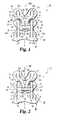
- FIG. 3is a diagrammatic view of a flexible elongated member for spinal constructs.
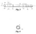
- FIG. 4is sectional view of the elongated member of FIG. 3 corresponding to section line 4 - 4 shown in FIG. 3 .
- FIG. 5is a flow chart of a spinal augmentation procedure.
- FIG. 6is a partial posterior view of another type of spinal augmentation implant system.
- FIG. 1illustrates spinal implant augmentation system 20 for spine S of patient P as viewed from the posterior along medial axis M.
- System 20includes a previously implanted spinal construct 30 that resulted in spinal fusion F of spine S.
- Construct 30includes several interconnected elements 30 a , such as elongated members 31 in the form of rods 31 a .
- Elements 30 a of construct 30also include two bone fasteners 32 fixed to each of rods 31 a .
- Fasteners 32each include bone screw 34 threaded into bone of spine S.
- System 20also includes augmentation construct 50 .
- Construct 50includes flexible polymer elongated members 51 that are each at least partially comprised of polyetheretherketone (PEEK) material, such as that provided by VICTREX, having an address of Victrex Technology Centre, Hillhouse International, Thornton Cleveleys, Lancashire FY5 4QD.
- Construct 50includes bone fasteners 52 that each includes a pedicle bone screw 53 .
- Pedicle bone screws 53are each threaded into a pedicle of adjacent spinal segment A. Spinal segment A is next to fusion F.
- construct 50is added to construct 30 to address degeneration of spinal segment A.
- Construct 50further includes connectors 54 and crosslink 55 .
- Connectors 54attach opposing ends of crosslink 55 to members 31 of construct 30 .
- Crosslink 55is also connected to elongated members 51 by connector 56 that is positioned between members 31 and connectors 54 .
- Elongated members 51each include end portion 57 a opposite end portion 57 b .
- Elongated members 51diverge from one another relative to a pathway from end portion 57 a towards end portion 57 b , and are alternatively designated legs 59 .
- elongated members 51each are shaped with two turns or bends 58 ; however, in other embodiments there may be more or fewer bends, if any.
- End portions 57 b of elongated members 51 and fasteners 52are each generally aligned with a corresponding rod 31 a and its respective fasteners 32 .
- Elongated members 51are generally symmetric along a plane perpendicular to the view plane of FIG. 1 that is also coincident with medial axis M.
- FIG. 2illustrates another augmentation system 120 relative to spine S of patient P that extends along medial axis M; where like reference numerals refer to like features.
- System 120includes previously implanted spinal construct 30 as described in connection with FIG. 1 .
- system 120includes augmentation construct 150 .
- construct 150includes crosslink 55 connected at opposite ends to members 31 by connectors 54 .
- construct 150includes flexible polymer elongated member 151 with a central bend 157 in addition to bends 158 . At central bend 157 , elongated member 151 is coupled to crosslink 55 by connector 156 .
- Elongated member 151is shaped with legs 159 that diverge from one another as they extend away from crosslink 55 .
- Elongated member 151is also symmetric about a plane through medial axis M that is approximately perpendicular to the view plane of FIG. 2 and generally aligns with members 31 and corresponding fasteners 32 where connected to spinal segment A by fasteners 52 .
- Elongated member 151also is at least partially comprised of PEEK material.
- fasteners 52again include pedicle bone screws 53 engaging pedicles of spinal segment A.
- Connections to fastener 52 and/or crosslink 55can be provided in any form, including, but not limited a rigid, hinged, multiaxial, and/or spherical configuration, to name a few representative examples.
- connectionscan include a tether, a fluid filled dashpot, or the like.
- FIGS. 3 and 4illustrate flexible and elastic elongated member 170 for spinal implantation that has longitudinal axis L.
- Elongated member 170is at least partially comprised of PEEK material 171 .
- Elongated memberfurther includes metallic sleeves 172 that are sized to slide along the elongated member 170 between slide stops 174 with a relatively snug fit, as represented by double-headed arrows in FIG. 3 .
- sleeves 172are engaged by a construct fastener (not shown) that constricts sleeve 172 in such a manner that is generally fixes the sleeve position along elongated member 170 .
- FIG. 4provides a sectional view of elongated member 170 corresponding to section line 4 - 4 shown in FIG.
- sleeves 172are generally concentric, and that elongated member 170 has an approximately circular cross section.
- sleeves 172may be differently composed and/or may be nonslidable—that is fixed in position along elongated member 172 .
- elongated members 51 , 151 , and 170each essentially consist of PEEK with the optional exception of connection sites and sleeves such as sleeves 172 .
- elongated member 51 and/or elongated member 151each include metallic sleeves.
- elongated members 51 , 151 , and/or 170are made of a different material that is flexible and relatively elastic compared to elongated members of a previously implanted construct.
- Such different materialincludes one or more of a metallic alloy, a polyetherketoneketoneetherkeytone (PEKKEK), an ultrahigh molecular weight polyethylene (UHMWPE), or a different thermoplastic or thermoset polymeric resin as would occur to those skilled in the art.
- elongated members 51 , 151 , and/or 170can be structurally arranged to provide a desired elasticity and/or flexibility, such as a braid or laminate of different materials, an elongated member having an inner core and outer layer(s) composed of different materials, a shape memory configuration, or the like.
- elongated members 51 , 151 , and/or 170are a type of rod having a generally cylindrical shape with a circular cross section; however, different shapes and corresponding cross sections can be used in different embodiments, forms, or variations. Furthermore, flexible polymer elongated members with changing shapes and/or cross sections can be employed in other embodiments.
- FIG. 5is a flowchart directed to spinal augmentation procedure 220 .
- a patientis identified that is experiencing degeneration of a spinal segment adjacent to a spinal fusion from a previously implanted spinal construct, such as construct 30 .
- a physiciandetermines and plans the implantation of an augmentation procedure that utilizes at least one flexible polymer rod or other type of elongated member.
- the physiciandecides whether to replace a previously implanted construct element, as represented by decision stage 230 . As shown in FIG.
- procedure 220continues in stage 232 with the substitution of at least one element, such as rod 31 a of construct 30 (see FIG. 1 ), with a flexible polymer elongated member, such as elongated member 170 , which is more specifically designated in the form of a rod in the FIG. 5 description of stage 232 but should not be limited to such form.
- the replacement elongated memberis connected to the adjacent degenerating spinal segment. The replacement of a more rigid elongated member of a previously implanted construct with a more flexible elongated member is arranged to provide further loading on the existing fusion mass in such a manner that more mature bone is created in response.
- stage 230If replacement is not indicated as tested by stage 230 (the “no” branch from stage 230 ), procedure 220 bypasses stages 232 and 234 and proceeds directly to decision stage 240 . Stage 240 is also reached after stage 234 is executed. Stage 240 tests whether to add a further construct, such as construct 50 or 150 , to the previously implanted construct, such as construct 30 . If addition is indicated (the “yes” branch from stage 240 ), procedure 220 continues with stage 242 . In stage 242 , a crosslink is implanted to bridge across members of the earlier implanted structure. One or more flexible polymer elongated members are connected to the crosslink and the adjacent degenerating spine segment in stage 244 . In the FIG.
- stage 244these elongated members are more specifically designated as rods, but should not be limited to such form. Stages 242 and 244 correspond to the addition of construct 50 or 150 of FIGS. 1 and 2 ; however, it should be appreciated that many other augmenting structures can be added as an alternative to either of these in other embodiments of procedure 220 .
- stage 250is reached in which procedure 220 is completed. Stage 250 can also be reached directly from stage 240 if the test of stage 240 is negative (the “no” branch is followed), which bypasses stages 242 and 244 . It should be appreciated that both replacement and addition can occur during procedure 220 . Also, other constructs besides those illustrated herein can be used that include one or more flexible polymer elongated members.
Landscapes
- Health & Medical Sciences (AREA)
- Orthopedic Medicine & Surgery (AREA)
- Life Sciences & Earth Sciences (AREA)
- Neurology (AREA)
- Surgery (AREA)
- Heart & Thoracic Surgery (AREA)
- Engineering & Computer Science (AREA)
- Biomedical Technology (AREA)
- Nuclear Medicine, Radiotherapy & Molecular Imaging (AREA)
- Medical Informatics (AREA)
- Molecular Biology (AREA)
- Animal Behavior & Ethology (AREA)
- General Health & Medical Sciences (AREA)
- Public Health (AREA)
- Veterinary Medicine (AREA)
- Prostheses (AREA)
- Surgical Instruments (AREA)
Abstract
Description
Claims (21)
Priority Applications (3)
| Application Number | Priority Date | Filing Date | Title |
|---|---|---|---|
| US11/118,645US7695499B2 (en) | 2005-04-29 | 2005-04-29 | System, devices and method for augmenting existing fusion constructs |
| PCT/US2006/016052WO2006118956A2 (en) | 2005-04-29 | 2006-04-27 | System, devices and method for augmenting existing fusion constructs |
| US12/798,625US20100198265A1 (en) | 2005-04-29 | 2010-04-08 | System, Devices and method for augmenting existing fusion constructs |
Applications Claiming Priority (1)
| Application Number | Priority Date | Filing Date | Title |
|---|---|---|---|
| US11/118,645US7695499B2 (en) | 2005-04-29 | 2005-04-29 | System, devices and method for augmenting existing fusion constructs |
Related Child Applications (1)
| Application Number | Title | Priority Date | Filing Date |
|---|---|---|---|
| US12/798,625DivisionUS20100198265A1 (en) | 2005-04-29 | 2010-04-08 | System, Devices and method for augmenting existing fusion constructs |
Publications (2)
| Publication Number | Publication Date |
|---|---|
| US20060247625A1 US20060247625A1 (en) | 2006-11-02 |
| US7695499B2true US7695499B2 (en) | 2010-04-13 |
Family
ID=36694467
Family Applications (2)
| Application Number | Title | Priority Date | Filing Date |
|---|---|---|---|
| US11/118,645Active2027-11-01US7695499B2 (en) | 2005-04-29 | 2005-04-29 | System, devices and method for augmenting existing fusion constructs |
| US12/798,625AbandonedUS20100198265A1 (en) | 2005-04-29 | 2010-04-08 | System, Devices and method for augmenting existing fusion constructs |
Family Applications After (1)
| Application Number | Title | Priority Date | Filing Date |
|---|---|---|---|
| US12/798,625AbandonedUS20100198265A1 (en) | 2005-04-29 | 2010-04-08 | System, Devices and method for augmenting existing fusion constructs |
Country Status (2)
| Country | Link |
|---|---|
| US (2) | US7695499B2 (en) |
| WO (1) | WO2006118956A2 (en) |
Cited By (3)
| Publication number | Priority date | Publication date | Assignee | Title |
|---|---|---|---|---|
| US20100298882A1 (en)* | 2009-05-20 | 2010-11-25 | Spine Wave, Inc. | Multi-Axial Cross Connector |
| US20100318131A1 (en)* | 2009-06-10 | 2010-12-16 | Spine Wave, Inc. | Devices and Methods for Adding an Additional Level of Fixation to an Existing Construct |
| US8337532B1 (en) | 2011-12-08 | 2012-12-25 | Spine Wave, Inc. | Methods for percutaneously extending an existing spinal construct |
Families Citing this family (7)
| Publication number | Priority date | Publication date | Assignee | Title |
|---|---|---|---|---|
| US8029548B2 (en) | 2008-05-05 | 2011-10-04 | Warsaw Orthopedic, Inc. | Flexible spinal stabilization element and system |
| US7695499B2 (en)* | 2005-04-29 | 2010-04-13 | Warsaw Orthopedic, Inc. | System, devices and method for augmenting existing fusion constructs |
| US8740941B2 (en)* | 2006-11-10 | 2014-06-03 | Lanx, Inc. | Pedicle based spinal stabilization with adjacent vertebral body support |
| US20090234388A1 (en)* | 2008-03-15 | 2009-09-17 | Warsaw Orthopedic, Inc. | Spinal Stabilization Connecting Element and System |
| FR2952522B1 (en)* | 2009-11-13 | 2012-04-27 | Neuro France Implants Nfi | DEVICE FOR RECOVERING AND STABILIZING A VERTEBRAL COLUMN |
| US10463403B2 (en) | 2017-07-31 | 2019-11-05 | Medos International Sarl | Systems and methods for reducing the risk of proximal junctional kyphosis using a bone anchor or other attachment point |
| US10456174B2 (en)* | 2017-07-31 | 2019-10-29 | Medos International Sarl | Connectors for use in systems and methods for reducing the risk of proximal junctional kyphosis |
Citations (64)
| Publication number | Priority date | Publication date | Assignee | Title |
|---|---|---|---|---|
| US4569338A (en) | 1984-02-09 | 1986-02-11 | Edwards Charles C | Sacral fixation device |
| US4805602A (en)* | 1986-11-03 | 1989-02-21 | Danninger Medical Technology | Transpedicular screw and rod system |
| US4827918A (en) | 1985-08-15 | 1989-05-09 | Sven Olerud | Fixing instrument for use in spinal surgery |
| US5047029A (en) | 1988-06-10 | 1991-09-10 | Synthes (U.S.A.) | Clamp and system for internal fixation |
| US5053034A (en) | 1990-08-03 | 1991-10-01 | Sven Olerud | Spinal joint |
| US5176680A (en) | 1990-02-08 | 1993-01-05 | Vignaud Jean Louis | Device for the adjustable fixing of spinal osteosynthesis rods |
| US5190543A (en) | 1990-11-26 | 1993-03-02 | Synthes (U.S.A.) | Anchoring device |
| US5234431A (en) | 1991-04-03 | 1993-08-10 | Waldemar Link Gmbh & Co. | Bone plate arrangement |
| US5254118A (en) | 1991-12-04 | 1993-10-19 | Srdjian Mirkovic | Three dimensional spine fixation system |
| US5261909A (en) | 1992-02-18 | 1993-11-16 | Danek Medical, Inc. | Variable angle screw for spinal implant system |
| US5282801A (en) | 1993-02-17 | 1994-02-01 | Danek Medical, Inc. | Top tightening clamp assembly for a spinal fixation system |
| US5437669A (en)* | 1993-08-12 | 1995-08-01 | Amei Technologies Inc. | Spinal fixation systems with bifurcated connectors |
| US5527314A (en) | 1993-01-04 | 1996-06-18 | Danek Medical, Inc. | Spinal fixation system |
| US5545166A (en) | 1994-07-14 | 1996-08-13 | Advanced Spine Fixation Systems, Incorporated | Spinal segmental reduction derotational fixation system |
| US5569247A (en) | 1995-03-27 | 1996-10-29 | Smith & Nephew Richards, Inc. | Enhanced variable angle bone bolt |
| US5591166A (en) | 1995-03-27 | 1997-01-07 | Smith & Nephew Richards, Inc. | Multi angle bone bolt |
| US5624441A (en) | 1993-08-19 | 1997-04-29 | Danek Medical, Inc. | Attachment plate for top-tightening clamp assembly in a spinal fixation system |
| US5628740A (en) | 1993-12-23 | 1997-05-13 | Mullane; Thomas S. | Articulating toggle bolt bone screw |
| US5643263A (en) | 1995-08-14 | 1997-07-01 | Simonson; Peter Melott | Spinal implant connection assembly |
| US5725528A (en) | 1997-02-12 | 1998-03-10 | Third Millennium Engineering, Llc | Modular polyaxial locking pedicle screw |
| US5735851A (en) | 1996-10-09 | 1998-04-07 | Third Millennium Engineering, Llc | Modular polyaxial locking pedicle screw |
| US5782833A (en) | 1996-12-20 | 1998-07-21 | Haider; Thomas T. | Pedicle screw system for osteosynthesis |
| US5800435A (en) | 1996-10-09 | 1998-09-01 | Techsys, Llc | Modular spinal plate for use with modular polyaxial locking pedicle screws |
| US5904683A (en) | 1998-07-10 | 1999-05-18 | Sulzer Spine-Tech Inc. | Anterior cervical vertebral stabilizing device |
| US5910142A (en) | 1998-10-19 | 1999-06-08 | Bones Consulting, Llc | Polyaxial pedicle screw having a rod clamping split ferrule coupling element |
| US5938663A (en) | 1995-03-06 | 1999-08-17 | Stryker France, S.A. | Spinal instruments, particularly for a rod |
| US5947967A (en) | 1997-10-22 | 1999-09-07 | Sdgt Holdings, Inc. | Variable angle connector |
| US6010504A (en) | 1993-10-08 | 2000-01-04 | Rogozinski; Chaim | Apparatus, method and system for the treatment of spinal conditions and fixation of pelvis and long bones |
| US6050997A (en) | 1999-01-25 | 2000-04-18 | Mullane; Thomas S. | Spinal fixation system |
| US6087467A (en) | 1988-02-17 | 2000-07-11 | Maxdem Incorporated | Rigid-rod polymers |
| US6113601A (en) | 1998-06-12 | 2000-09-05 | Bones Consulting, Llc | Polyaxial pedicle screw having a loosely coupled locking cap |
| US6132432A (en) | 1996-10-18 | 2000-10-17 | Spinal Innovations Llc | Spinal implant fixation assembly |
| US6183473B1 (en) | 1999-04-21 | 2001-02-06 | Richard B Ashman | Variable angle connection assembly for a spinal implant system |
| US6187005B1 (en) | 1998-09-11 | 2001-02-13 | Synthes (Usa) | Variable angle spinal fixation system |
| US6190388B1 (en)* | 1995-06-07 | 2001-02-20 | Gary K. Michelson | Anterior spinal instrumentation and method for implantation and revision |
| US6210413B1 (en) | 1999-04-23 | 2001-04-03 | Sdgi Holdings, Inc. | Connecting apparatus using shape-memory technology |
| US6248107B1 (en) | 2000-03-15 | 2001-06-19 | Sdgi Holdings, Inc. | System for reducing the displacement of a vertebra |
| US6267765B1 (en) | 1997-06-03 | 2001-07-31 | Jean Taylor | Multidirectional adaptable vertebral osteosyntsis device with reduced space requirement |
| US6315779B1 (en) | 1999-04-16 | 2001-11-13 | Sdgi Holdings, Inc. | Multi-axial bone anchor system |
| US6352537B1 (en) | 1998-09-17 | 2002-03-05 | Electro-Biology, Inc. | Method and apparatus for spinal fixation |
| US6355038B1 (en) | 1998-09-25 | 2002-03-12 | Perumala Corporation | Multi-axis internal spinal fixation |
| US20020068975A1 (en) | 2000-06-23 | 2002-06-06 | Teitelbaum George P. | Formable orthopedic fixation system with cross linking |
| US6478798B1 (en) | 2001-05-17 | 2002-11-12 | Robert S. Howland | Spinal fixation apparatus and methods for use |
| US6485491B1 (en) | 2000-09-15 | 2002-11-26 | Sdgi Holdings, Inc. | Posterior fixation system |
| US20020198526A1 (en) | 2000-06-23 | 2002-12-26 | Shaolian Samuel M. | Formed in place fixation system with thermal acceleration |
| US6520962B1 (en) | 2000-10-23 | 2003-02-18 | Sdgi Holdings, Inc. | Taper-locked adjustable connector |
| US6524315B1 (en) | 2000-08-08 | 2003-02-25 | Depuy Acromed, Inc. | Orthopaedic rod/plate locking mechanism |
| US6562038B1 (en) | 2000-03-15 | 2003-05-13 | Sdgi Holdings, Inc. | Spinal implant connection assembly |
| US6582441B1 (en) | 2000-02-24 | 2003-06-24 | Advanced Bionics Corporation | Surgical insertion tool |
| US6626906B1 (en) | 2000-10-23 | 2003-09-30 | Sdgi Holdings, Inc. | Multi-planar adjustable connector |
| US6685705B1 (en) | 2000-10-23 | 2004-02-03 | Sdgi Holdings, Inc. | Six-axis and seven-axis adjustable connector |
| US20040030392A1 (en) | 1999-08-18 | 2004-02-12 | Lambrecht Greg. H. | Method of supporting nucleus pulposus |
| US20040049189A1 (en)* | 2000-07-25 | 2004-03-11 | Regis Le Couedic | Flexible linking piece for stabilising the spine |
| US6770075B2 (en) | 2001-05-17 | 2004-08-03 | Robert S. Howland | Spinal fixation apparatus with enhanced axial support and methods for use |
| US6783527B2 (en) | 2001-10-30 | 2004-08-31 | Sdgi Holdings, Inc. | Flexible spinal stabilization system and method |
| US20040220668A1 (en) | 2003-02-12 | 2004-11-04 | Sdgi Holdings, Inc. | Method and device for correcting spondylolisthesis from the lateral approach |
| US20040230309A1 (en) | 2003-02-14 | 2004-11-18 | Depuy Spine, Inc. | In-situ formed intervertebral fusion device and method |
| US20050021031A1 (en) | 1999-10-20 | 2005-01-27 | Foley Kevin T. | Instruments and methods for stabilization of bony structures |
| US20050038432A1 (en) | 2003-04-25 | 2005-02-17 | Shaolian Samuel M. | Articulating spinal fixation rod and system |
| US20050065516A1 (en) | 2003-09-24 | 2005-03-24 | Tae-Ahn Jahng | Method and apparatus for flexible fixation of a spine |
| US6875212B2 (en) | 2000-06-23 | 2005-04-05 | Vertelink Corporation | Curable media for implantable medical device |
| US20060052785A1 (en)* | 2004-08-18 | 2006-03-09 | Augostino Teena M | Adjacent level facet arthroplasty devices, spine stabilization systems, and methods |
| US20060058791A1 (en)* | 2004-08-18 | 2006-03-16 | Richard Broman | Implantable spinal device revision system |
| US20070088359A1 (en)* | 2005-02-07 | 2007-04-19 | Woods Richard W | Universal dynamic spine stabilization device and method of use |
Family Cites Families (2)
| Publication number | Priority date | Publication date | Assignee | Title |
|---|---|---|---|---|
| US6562441B1 (en)* | 1999-11-19 | 2003-05-13 | Oji Paper Co., Ltd. | Ink jet recording medium |
| US7695499B2 (en)* | 2005-04-29 | 2010-04-13 | Warsaw Orthopedic, Inc. | System, devices and method for augmenting existing fusion constructs |
- 2005
- 2005-04-29USUS11/118,645patent/US7695499B2/enactiveActive
- 2006
- 2006-04-27WOPCT/US2006/016052patent/WO2006118956A2/enactiveApplication Filing
- 2010
- 2010-04-08USUS12/798,625patent/US20100198265A1/ennot_activeAbandoned
Patent Citations (72)
| Publication number | Priority date | Publication date | Assignee | Title |
|---|---|---|---|---|
| US4569338A (en) | 1984-02-09 | 1986-02-11 | Edwards Charles C | Sacral fixation device |
| US4827918A (en) | 1985-08-15 | 1989-05-09 | Sven Olerud | Fixing instrument for use in spinal surgery |
| US4805602A (en)* | 1986-11-03 | 1989-02-21 | Danninger Medical Technology | Transpedicular screw and rod system |
| US6087467A (en) | 1988-02-17 | 2000-07-11 | Maxdem Incorporated | Rigid-rod polymers |
| US5047029A (en) | 1988-06-10 | 1991-09-10 | Synthes (U.S.A.) | Clamp and system for internal fixation |
| US5176680A (en) | 1990-02-08 | 1993-01-05 | Vignaud Jean Louis | Device for the adjustable fixing of spinal osteosynthesis rods |
| US5053034A (en) | 1990-08-03 | 1991-10-01 | Sven Olerud | Spinal joint |
| US5190543A (en) | 1990-11-26 | 1993-03-02 | Synthes (U.S.A.) | Anchoring device |
| US5234431A (en) | 1991-04-03 | 1993-08-10 | Waldemar Link Gmbh & Co. | Bone plate arrangement |
| US5254118A (en) | 1991-12-04 | 1993-10-19 | Srdjian Mirkovic | Three dimensional spine fixation system |
| US5261909A (en) | 1992-02-18 | 1993-11-16 | Danek Medical, Inc. | Variable angle screw for spinal implant system |
| US5562662A (en) | 1993-01-04 | 1996-10-08 | Danek Medical Inc. | Spinal fixation system and method |
| US5527314A (en) | 1993-01-04 | 1996-06-18 | Danek Medical, Inc. | Spinal fixation system |
| US5534002A (en) | 1993-01-04 | 1996-07-09 | Danek Medical, Inc. | Spinal fixation system |
| US5282801A (en) | 1993-02-17 | 1994-02-01 | Danek Medical, Inc. | Top tightening clamp assembly for a spinal fixation system |
| US5437669A (en)* | 1993-08-12 | 1995-08-01 | Amei Technologies Inc. | Spinal fixation systems with bifurcated connectors |
| US5624441A (en) | 1993-08-19 | 1997-04-29 | Danek Medical, Inc. | Attachment plate for top-tightening clamp assembly in a spinal fixation system |
| US6010504A (en) | 1993-10-08 | 2000-01-04 | Rogozinski; Chaim | Apparatus, method and system for the treatment of spinal conditions and fixation of pelvis and long bones |
| US5628740A (en) | 1993-12-23 | 1997-05-13 | Mullane; Thomas S. | Articulating toggle bolt bone screw |
| US5545166A (en) | 1994-07-14 | 1996-08-13 | Advanced Spine Fixation Systems, Incorporated | Spinal segmental reduction derotational fixation system |
| US5938663A (en) | 1995-03-06 | 1999-08-17 | Stryker France, S.A. | Spinal instruments, particularly for a rod |
| US5569247A (en) | 1995-03-27 | 1996-10-29 | Smith & Nephew Richards, Inc. | Enhanced variable angle bone bolt |
| US5591166A (en) | 1995-03-27 | 1997-01-07 | Smith & Nephew Richards, Inc. | Multi angle bone bolt |
| US6190388B1 (en)* | 1995-06-07 | 2001-02-20 | Gary K. Michelson | Anterior spinal instrumentation and method for implantation and revision |
| US5885285A (en) | 1995-08-14 | 1999-03-23 | Simonson; Peter Melott | Spinal implant connection assembly |
| US5643263A (en) | 1995-08-14 | 1997-07-01 | Simonson; Peter Melott | Spinal implant connection assembly |
| US5735851A (en) | 1996-10-09 | 1998-04-07 | Third Millennium Engineering, Llc | Modular polyaxial locking pedicle screw |
| US5800435A (en) | 1996-10-09 | 1998-09-01 | Techsys, Llc | Modular spinal plate for use with modular polyaxial locking pedicle screws |
| US6132432A (en) | 1996-10-18 | 2000-10-17 | Spinal Innovations Llc | Spinal implant fixation assembly |
| US5782833A (en) | 1996-12-20 | 1998-07-21 | Haider; Thomas T. | Pedicle screw system for osteosynthesis |
| US5725528A (en) | 1997-02-12 | 1998-03-10 | Third Millennium Engineering, Llc | Modular polyaxial locking pedicle screw |
| US6267765B1 (en) | 1997-06-03 | 2001-07-31 | Jean Taylor | Multidirectional adaptable vertebral osteosyntsis device with reduced space requirement |
| US5947967A (en) | 1997-10-22 | 1999-09-07 | Sdgt Holdings, Inc. | Variable angle connector |
| US6113601A (en) | 1998-06-12 | 2000-09-05 | Bones Consulting, Llc | Polyaxial pedicle screw having a loosely coupled locking cap |
| US5904683A (en) | 1998-07-10 | 1999-05-18 | Sulzer Spine-Tech Inc. | Anterior cervical vertebral stabilizing device |
| US6187005B1 (en) | 1998-09-11 | 2001-02-13 | Synthes (Usa) | Variable angle spinal fixation system |
| US6352537B1 (en) | 1998-09-17 | 2002-03-05 | Electro-Biology, Inc. | Method and apparatus for spinal fixation |
| US6355038B1 (en) | 1998-09-25 | 2002-03-12 | Perumala Corporation | Multi-axis internal spinal fixation |
| US5910142A (en) | 1998-10-19 | 1999-06-08 | Bones Consulting, Llc | Polyaxial pedicle screw having a rod clamping split ferrule coupling element |
| US6050997A (en) | 1999-01-25 | 2000-04-18 | Mullane; Thomas S. | Spinal fixation system |
| US6315779B1 (en) | 1999-04-16 | 2001-11-13 | Sdgi Holdings, Inc. | Multi-axial bone anchor system |
| US6183473B1 (en) | 1999-04-21 | 2001-02-06 | Richard B Ashman | Variable angle connection assembly for a spinal implant system |
| US6210413B1 (en) | 1999-04-23 | 2001-04-03 | Sdgi Holdings, Inc. | Connecting apparatus using shape-memory technology |
| US20040034429A1 (en) | 1999-08-18 | 2004-02-19 | Lambrecht Gregg H, | Anchored anulus method |
| US20040030392A1 (en) | 1999-08-18 | 2004-02-12 | Lambrecht Greg. H. | Method of supporting nucleus pulposus |
| US20050021031A1 (en) | 1999-10-20 | 2005-01-27 | Foley Kevin T. | Instruments and methods for stabilization of bony structures |
| US6582441B1 (en) | 2000-02-24 | 2003-06-24 | Advanced Bionics Corporation | Surgical insertion tool |
| US6562038B1 (en) | 2000-03-15 | 2003-05-13 | Sdgi Holdings, Inc. | Spinal implant connection assembly |
| US6248107B1 (en) | 2000-03-15 | 2001-06-19 | Sdgi Holdings, Inc. | System for reducing the displacement of a vertebra |
| US20020198526A1 (en) | 2000-06-23 | 2002-12-26 | Shaolian Samuel M. | Formed in place fixation system with thermal acceleration |
| US20040082954A1 (en) | 2000-06-23 | 2004-04-29 | Teitelbaum George P. | Formable orthopedic fixation system with cross linking |
| US6875212B2 (en) | 2000-06-23 | 2005-04-05 | Vertelink Corporation | Curable media for implantable medical device |
| US6749614B2 (en) | 2000-06-23 | 2004-06-15 | Vertelink Corporation | Formable orthopedic fixation system with cross linking |
| US20020068975A1 (en) | 2000-06-23 | 2002-06-06 | Teitelbaum George P. | Formable orthopedic fixation system with cross linking |
| US20040049189A1 (en)* | 2000-07-25 | 2004-03-11 | Regis Le Couedic | Flexible linking piece for stabilising the spine |
| US6524315B1 (en) | 2000-08-08 | 2003-02-25 | Depuy Acromed, Inc. | Orthopaedic rod/plate locking mechanism |
| US6547790B2 (en) | 2000-08-08 | 2003-04-15 | Depuy Acromed, Inc. | Orthopaedic rod/plate locking mechanisms and surgical methods |
| US6485491B1 (en) | 2000-09-15 | 2002-11-26 | Sdgi Holdings, Inc. | Posterior fixation system |
| US6520962B1 (en) | 2000-10-23 | 2003-02-18 | Sdgi Holdings, Inc. | Taper-locked adjustable connector |
| US6685705B1 (en) | 2000-10-23 | 2004-02-03 | Sdgi Holdings, Inc. | Six-axis and seven-axis adjustable connector |
| US6626906B1 (en) | 2000-10-23 | 2003-09-30 | Sdgi Holdings, Inc. | Multi-planar adjustable connector |
| US6478798B1 (en) | 2001-05-17 | 2002-11-12 | Robert S. Howland | Spinal fixation apparatus and methods for use |
| US6770075B2 (en) | 2001-05-17 | 2004-08-03 | Robert S. Howland | Spinal fixation apparatus with enhanced axial support and methods for use |
| US6783527B2 (en) | 2001-10-30 | 2004-08-31 | Sdgi Holdings, Inc. | Flexible spinal stabilization system and method |
| US20040220668A1 (en) | 2003-02-12 | 2004-11-04 | Sdgi Holdings, Inc. | Method and device for correcting spondylolisthesis from the lateral approach |
| US20040230309A1 (en) | 2003-02-14 | 2004-11-18 | Depuy Spine, Inc. | In-situ formed intervertebral fusion device and method |
| US20050038432A1 (en) | 2003-04-25 | 2005-02-17 | Shaolian Samuel M. | Articulating spinal fixation rod and system |
| US20050065516A1 (en) | 2003-09-24 | 2005-03-24 | Tae-Ahn Jahng | Method and apparatus for flexible fixation of a spine |
| US20050065515A1 (en) | 2003-09-24 | 2005-03-24 | Tae-Ahn Jahng | Marking and guidance method and system for flexible fixation of a spine |
| US20060052785A1 (en)* | 2004-08-18 | 2006-03-09 | Augostino Teena M | Adjacent level facet arthroplasty devices, spine stabilization systems, and methods |
| US20060058791A1 (en)* | 2004-08-18 | 2006-03-16 | Richard Broman | Implantable spinal device revision system |
| US20070088359A1 (en)* | 2005-02-07 | 2007-04-19 | Woods Richard W | Universal dynamic spine stabilization device and method of use |
Non-Patent Citations (3)
| Title |
|---|
| Pass® Deformity System, Encore Surgical, © Jan. 2002. |
| Spine Internal Fixation Device, Encore Surgical, © Jan. 2002. |
| TiMX Comprehensive Low Back System, DePuy AcroMed, © 1999. |
Cited By (22)
| Publication number | Priority date | Publication date | Assignee | Title |
|---|---|---|---|---|
| US20100298882A1 (en)* | 2009-05-20 | 2010-11-25 | Spine Wave, Inc. | Multi-Axial Cross Connector |
| US8940021B2 (en) | 2009-05-20 | 2015-01-27 | Spine Wave, Inc. | Multi-axial cross connector |
| US8372120B2 (en) | 2009-05-20 | 2013-02-12 | Spine Wave, Inc. | Multi-axial cross connector |
| US20100318131A1 (en)* | 2009-06-10 | 2010-12-16 | Spine Wave, Inc. | Devices and Methods for Adding an Additional Level of Fixation to an Existing Construct |
| US8430913B2 (en) | 2009-06-10 | 2013-04-30 | Spine Wave, Inc. | Devices and methods for adding an additional level of fixation to an existing construct |
| US8740950B2 (en) | 2011-12-08 | 2014-06-03 | Spine Wave, Inc. | Methods for percutaneously attaching a cross connector to contralateral spinal constructs |
| US9629668B2 (en) | 2011-12-08 | 2017-04-25 | Spine Wave, Inc. | Apparatus and devices for percutaneously extending an existing spinal construct |
| US8641739B2 (en) | 2011-12-08 | 2014-02-04 | Spine Wave, Inc. | Methods for percutaneously extending an existing spinal construct |
| US8657826B2 (en) | 2011-12-08 | 2014-02-25 | Spine Wave, Inc. | Apparatus and devices for percutaneously extending an existing spinal construct |
| US8663281B2 (en) | 2011-12-08 | 2014-03-04 | Spine Wave, Inc. | Apparatus and instruments for percutaneously extending an existing spinal construct |
| US8523906B2 (en) | 2011-12-08 | 2013-09-03 | Spine Wave, Inc. | Apparatus and devices for percutaneously extending an existing spinal construct |
| US8337532B1 (en) | 2011-12-08 | 2012-12-25 | Spine Wave, Inc. | Methods for percutaneously extending an existing spinal construct |
| US9113962B2 (en) | 2011-12-08 | 2015-08-25 | Spine Wave, Inc. | Apparatus and devices for percutaneously extending an existing spinal construct |
| US9149302B2 (en) | 2011-12-08 | 2015-10-06 | Spine Wave, Inc. | Apparatus and devices for percutaneously extending an existing spinal construct |
| US8562654B2 (en) | 2011-12-08 | 2013-10-22 | Spine Wave, Inc. | Methods for percutaneously extending an existing spinal construct |
| US9642655B2 (en) | 2011-12-08 | 2017-05-09 | Spine Wave, Inc. | Methods for percutaneously extending an existing spinal construct |
| US9655660B2 (en) | 2011-12-08 | 2017-05-23 | Spine Wave, Inc. | Methods for percutaneously extending an existing spinal construct |
| US10016227B2 (en) | 2011-12-08 | 2018-07-10 | Spine Wave, Inc. | Methods for percutaneously extending an existing spinal construct |
| US10456176B2 (en) | 2011-12-08 | 2019-10-29 | Spine Wave, Inc. | Apparatus and devices for percutaneously extending an existing spinal construct |
| US10667848B2 (en) | 2011-12-08 | 2020-06-02 | Spine Wave, Inc. | Apparatus and method for percutaneously extending an existing spinal construct |
| US11160587B2 (en) | 2011-12-08 | 2021-11-02 | Spine Wave, Inc. | Rod connector for attachment to an existing spinal rod |
| US11696787B2 (en) | 2011-12-08 | 2023-07-11 | Spine Wave, Inc. | Apparatus and method for percutaneously extending an existing spinal construct |
Also Published As
| Publication number | Publication date |
|---|---|
| US20100198265A1 (en) | 2010-08-05 |
| US20060247625A1 (en) | 2006-11-02 |
| WO2006118956A2 (en) | 2006-11-09 |
Similar Documents
| Publication | Publication Date | Title |
|---|---|---|
| US20100198265A1 (en) | System, Devices and method for augmenting existing fusion constructs | |
| US7722649B2 (en) | Dynamic stabilization device for bones, in particular for vertebrae | |
| US8425562B2 (en) | Systems and devices for dynamic stabilization of the spine | |
| US8449576B2 (en) | Dynamic fixation system | |
| US20100262192A1 (en) | Systems and Devices for Dynamic Stabilization of the Spine | |
| US8202301B2 (en) | Dynamic spinal rod and implantation method | |
| US8206422B2 (en) | Spine stiffening device and associated method | |
| US7806914B2 (en) | Dynamic spinal stabilization system | |
| US7744630B2 (en) | Facet repair and stabilization | |
| US9492202B2 (en) | Rod-shaped implant element for the application in spine surgery or trauma surgery and stabilization device with such a rod-shaped implant element | |
| KR101446620B1 (en) | Spinal support device | |
| US8206419B2 (en) | Systems and devices for dynamic stabilization of the spine | |
| US7993375B2 (en) | Dynamic stabilization devices and methods | |
| US20080033433A1 (en) | Dynamic spinal stabilization device | |
| JP2009502213A (en) | Mobile spine stabilization device | |
| US7822465B2 (en) | Device and method for image-based device performance measurement | |
| US20080015577A1 (en) | Spinal Correction Device | |
| CN104080415B (en) | Vertebral anatomy and using method | |
| KR20100051617A (en) | Dynamic cable system | |
| TW201332509A (en) | Intersegment motion preservation system for use in the spine and methods for use thereof | |
| US20160030090A1 (en) | Modular polyaxial bone screw | |
| US20080183217A1 (en) | Posterior Vertebra Locking Plate | |
| JP2020529248A (en) | Systems and methods for reducing the risk of proximal adjacent kyphosis deformity using bone anchors or other attachment points | |
| US20120277798A1 (en) | Spinal Rod Construct to Limit Facet Impingement | |
| US20100292794A1 (en) | Device for implanting in a human or animal vertebral column |
Legal Events
| Date | Code | Title | Description |
|---|---|---|---|
| AS | Assignment | Owner name:SDGI HOLDINGS, INC.,DELAWARE Free format text:ASSIGNMENT OF ASSIGNORS INTEREST;ASSIGNORS:MORRISON, MATTHEW M.;ANDERSON, KENT M.;DEWEY, JONATHAN;AND OTHERS;SIGNING DATES FROM 20050420 TO 20050426;REEL/FRAME:016523/0464 Owner name:SDGI HOLDINGS, INC., DELAWARE Free format text:ASSIGNMENT OF ASSIGNORS INTEREST;ASSIGNORS:MORRISON, MATTHEW M.;ANDERSON, KENT M.;DEWEY, JONATHAN;AND OTHERS;REEL/FRAME:016523/0464;SIGNING DATES FROM 20050420 TO 20050426 | |
| AS | Assignment | Owner name:SDGI HOLDINGS, INC.,DELAWARE Free format text:CORRECTED COVER SHEET TO ADD INVENTOR'S NAME, PREVIOUSLY OMITTED FROM REEL/FRAME 016523/0464 (ASSIGNMENT OF ASSIGNOR'S INTEREST);ASSIGNOR:BRUNEAU, AURELIEN;REEL/FRAME:018100/0706 Effective date:20050421 Owner name:SDGI HOLDINGS, INC., DELAWARE Free format text:CORRECTED COVER SHEET TO ADD INVENTOR'S NAME, PREVIOUSLY OMITTED FROM REEL/FRAME 016523/0464 (ASSIGNMENT OF ASSIGNOR'S INTEREST);ASSIGNOR:BRUNEAU, AURELIEN;REEL/FRAME:018100/0706 Effective date:20050421 | |
| AS | Assignment | Owner name:WARSAW ORTHOPEDIC, INC.,INDIANA Free format text:MERGER;ASSIGNOR:SDGI HOLDINGS, INC.;REEL/FRAME:020558/0116 Effective date:20060428 Owner name:WARSAW ORTHOPEDIC, INC., INDIANA Free format text:MERGER;ASSIGNOR:SDGI HOLDINGS, INC.;REEL/FRAME:020558/0116 Effective date:20060428 | |
| STCF | Information on status: patent grant | Free format text:PATENTED CASE | |
| FPAY | Fee payment | Year of fee payment:4 | |
| MAFP | Maintenance fee payment | Free format text:PAYMENT OF MAINTENANCE FEE, 8TH YEAR, LARGE ENTITY (ORIGINAL EVENT CODE: M1552) Year of fee payment:8 | |
| MAFP | Maintenance fee payment | Free format text:PAYMENT OF MAINTENANCE FEE, 12TH YEAR, LARGE ENTITY (ORIGINAL EVENT CODE: M1553); ENTITY STATUS OF PATENT OWNER: LARGE ENTITY Year of fee payment:12 |