US7695477B2 - Milling system and methods for resecting a joint articulation surface - Google Patents
Milling system and methods for resecting a joint articulation surfaceDownload PDFInfo
- Publication number
- US7695477B2 US7695477B2US11/138,016US13801605AUS7695477B2US 7695477 B2US7695477 B2US 7695477B2US 13801605 AUS13801605 AUS 13801605AUS 7695477 B2US7695477 B2US 7695477B2
- Authority
- US
- United States
- Prior art keywords
- template
- guide
- recited
- base
- milling system
- Prior art date
- Legal status (The legal status is an assumption and is not a legal conclusion. Google has not performed a legal analysis and makes no representation as to the accuracy of the status listed.)
- Expired - Fee Related, expires
Links
Images


Classifications
- A—HUMAN NECESSITIES
- A61—MEDICAL OR VETERINARY SCIENCE; HYGIENE
- A61B—DIAGNOSIS; SURGERY; IDENTIFICATION
- A61B17/00—Surgical instruments, devices or methods
- A61B17/16—Instruments for performing osteoclasis; Drills or chisels for bones; Trepans
- A61B17/17—Guides or aligning means for drills, mills, pins or wires
- A61B17/1739—Guides or aligning means for drills, mills, pins or wires specially adapted for particular parts of the body
- A61B17/1764—Guides or aligning means for drills, mills, pins or wires specially adapted for particular parts of the body for the knee
- A61B17/1767—Guides or aligning means for drills, mills, pins or wires specially adapted for particular parts of the body for the knee for the patella
- A—HUMAN NECESSITIES
- A61—MEDICAL OR VETERINARY SCIENCE; HYGIENE
- A61B—DIAGNOSIS; SURGERY; IDENTIFICATION
- A61B17/00—Surgical instruments, devices or methods
- A61B17/16—Instruments for performing osteoclasis; Drills or chisels for bones; Trepans
- A61B17/1662—Instruments for performing osteoclasis; Drills or chisels for bones; Trepans for particular parts of the body
- A61B17/1675—Instruments for performing osteoclasis; Drills or chisels for bones; Trepans for particular parts of the body for the knee
- A—HUMAN NECESSITIES
- A61—MEDICAL OR VETERINARY SCIENCE; HYGIENE
- A61B—DIAGNOSIS; SURGERY; IDENTIFICATION
- A61B17/00—Surgical instruments, devices or methods
- A61B17/16—Instruments for performing osteoclasis; Drills or chisels for bones; Trepans
- A61B2017/1602—Mills
- A—HUMAN NECESSITIES
- A61—MEDICAL OR VETERINARY SCIENCE; HYGIENE
- A61B—DIAGNOSIS; SURGERY; IDENTIFICATION
- A61B90/00—Instruments, implements or accessories specially adapted for surgery or diagnosis and not covered by any of the groups A61B1/00 - A61B50/00, e.g. for luxation treatment or for protecting wound edges
- A61B90/03—Automatic limiting or abutting means, e.g. for safety
- A61B2090/033—Abutting means, stops, e.g. abutting on tissue or skin
- A61B2090/034—Abutting means, stops, e.g. abutting on tissue or skin abutting on parts of the device itself
- A—HUMAN NECESSITIES
- A61—MEDICAL OR VETERINARY SCIENCE; HYGIENE
- A61B—DIAGNOSIS; SURGERY; IDENTIFICATION
- A61B90/00—Instruments, implements or accessories specially adapted for surgery or diagnosis and not covered by any of the groups A61B1/00 - A61B50/00, e.g. for luxation treatment or for protecting wound edges
- A61B90/06—Measuring instruments not otherwise provided for
- A61B2090/062—Measuring instruments not otherwise provided for penetration depth
Definitions
- the present inventionrelates to milling systems and related guides and mills for resecting at least a portion of a joint articulation surface of a bone and mounting an implant thereat.
- the human bodyhas a variety of movable orthopedic joints such as the knee joint, hip joint, shoulder joint, and the like. These joints are formed by the intersection of two bones.
- the intersecting end of each bonehas a smooth articular surface that is comprised of articular cartilage.
- This procedureis referred to as a joint replacement or arthroplasty.
- a total knee arthroplastycomprises cutting off or resecting the articular surfaces at both the distal end of the femur and the proximal end of the tibia.
- Complementary artificial implantsare then mounted on the distal end of the femur and the proximal end of the tibia. Where only a portion of a joint is damaged, a partial joint arthroplasty can be performed. In this procedure, one or more artificial implants replace only a portion of a joint.
- joint replacementis now a common procedure that has met with popular success, conventional implants and related mounting techniques have significant shortcomings.
- One significant drawback of many joint replacementsis the extended and painful patient recovery.
- a traditional knee replacementrequires an open procedure wherein a relatively large incision is made which severs a portion of the muscle bounding the femur. The large incision is made so as to fully expose the respective ends of the femur and tibia.
- the implantsare formed with posts projecting therefrom. The posts are received within sockets formed on the resected end face of the tibia and femur. Forming of the sockets and inserting the posts into the sockets requires substantially full exposure of the resected end face of the tibia and femur.
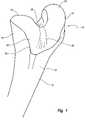
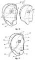
- FIG. 1is a perspective view of the distal end of a femur having a trochlear groove
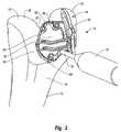
- FIG. 2is a perspective view of a guide system portion of a milling system mounted on the femur of FIG. 1 ;
- FIG. 3is a perspective view of the guide system shown in FIG. 2 ;
- FIG. 4is an elevated left side view of the guide system shown in FIG. 3 ;
- FIG. 5is an elevated front view of the guide system shown in FIG. 3 ;
- FIG. 6is a bottom perspective view of the guide system shown in FIG. 3 ;
- FIG. 7is an exploded view of the guide of the guide system shown in FIG. 3 ;
- FIG. 8is a perspective view of the complete milling system mounted on the femur of FIG. 1 ;
- FIG. 9is a disassembled view of the mill assembly of the milling system shown in FIG. 8 ;
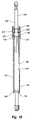
- FIG. 10is a cross sectional side view of the mill assembly shown in FIG. 9 ;
- FIG. 11is a bottom perspective view of the retainer of the mill assembly shown in FIG. 9 ;
- FIG. 12is a disassembled perspective view of the guide system, brace, and shackle of the milling system shown in FIG. 8 ;
- FIG. 13is a perspective view of the femur shown in FIG. 1 having an incompleted pocket formed thereon by the milling assembly shown in FIG. 8 ;
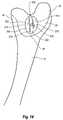
- FIG. 14is a perspective view of the femur shown in FIG. 13 having the completed pocket formed thereon;
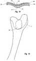
- FIG. 15is a top perspective view of a trochlear implant
- FIG. 16is a bottom perspective exploded view of the implant shown in FIG. 15 ;
- FIG. 17is a bottom perspective view of the implant shown in FIG. 15 having a line coupled therewith;
- FIG. 18is a cross sectional side view of the implant shown in FIG. 15 along line 18 - 18 ;
- FIG. 19is a perspective view of the femur shown in FIG. 14 having the implant of FIG. 16 mounted in the pocket thereof.
- the present inventionrelates to milling systems and related guides and mills for use in resecting an articulation surface of an orthopedic joint so that an implant can be mounted on the resected surface.
- articulation surfaceis broadly intended to include all surfaces of natural articular cartilage forming a portion of an orthopedic joint and all articulation wear surfaces of a bone forming a portion of orthopedic joint that, as a result of wear, trauma, disease or other causes, have all or a portion of the natural articular cartilage removed.
- milling systems and related guides and millsare shown which are specifically designed for mounting a trochlear groove implant at the distal end of a femur. It is appreciated, however, that the illustrated embodiments are simply examples of the present invention and that the same technology can also be used for resecting a portion of the articulation surface at a different location on the same articulation surface or on a variety of other joint surfaces to receive a variety of other different types of implants.
- the present inventioncan be used for resecting all or a portion of a condyle and then mounting a unicondylar or partial implant.
- the present inventioncan also be used for resurfacing an articulation surface of a knee joint, ankle joint, hip joint, shoulder joint, elbow joint, wrist joint, interfrangial joint, or other joints.
- the milling systems of the present inventioncan be used for preparing the articulation surface at the proximal or distal end of the femur, tibia, humors, radius, and ulna and on other articulation surfaces of the scapula, pelvis, bones within the foot and hand, and other bone articulation surfaces.
- FIG. 1Depicted in FIG. 1 is a distal end 10 of a femur 12 .
- Distal end 10has a medial side 14 and a lateral side 16 that each extend between an anterior side 18 and a posterior side 20 .
- Distal end 10 of femur 12terminates at a medial condyle 22 and a lateral condyle 24 with a trochlear groove 26 disposed therebetween.
- Articular cartilage 28defines an articulation surface for distal end 10 of femur 12 .
- Articular cartilage 28terminates at a margin 30 .
- Trochlear groove 26is a channel that guides the movement of the patella as the knee flexes. On occasion, due to arthritis, disease, trauma, or the like, it is necessary to replace a portion of the femur forming the trochlear groove.
- the illustrated milling system and related guides and millsare designed to form a recessed pocket on femur 12 at the location of trochlear groove 26 so that an implant can be mounted within the recessed pocket.
- guide system 36mounted on distal end 10 of femur 12 over trochlear grove 26 .
- Guide system 36forms a portion of the milling system.
- guide system 36comprises a template 38 having a guide 40 moveably mounted thereon.
- Template 38comprises an annular base 42 having a top surface 44 and an opposing bottom surface 46 that each extend between a first end 48 and an opposing second end 50 .
- Surfaces 44 and 46also extend between a first side 52 and an opposing second side 54 .
- Base 42can also be defined in terms of having opposing side portions 31 and 32 that extend between a first end portion 33 and an opposing second end portion 34 .
- side portions 31 and 32 of base 42have a substantially continuous arch extending from first end 48 to opposing second end 50 . That is, bottom surface 46 has a substantially constant concave curvature while the top surface 44 has a substantially constant convex curvature. This configuration helps to minimize the size of template 38 to facilitate the greatest ease of insertion during use. In alternative embodiments, however, one or both of top surface 44 and bottom surface 46 can be flat or have any other desired configuration.
- end portions 33 and 34 of base 42have a substantially V-shaped configuration such that template 38 can sit within trochlear groove 26 ( FIG. 1 ).
- end portions 33 and 34need not be V-shaped but can be substantially flat or partially curved.
- Base 42is typically designed so as to have a contour complementary to the contour of the portion of the bone over which base 42 sits during use.
- base 42also has an interior surface 56 which bounds an opening 58 that extends through base 42 between top surface 44 and bottom surface 46 .
- opening 58generally corresponds to the size of the pocket that will be formed on the bone. It is appreciated that opening 58 can have a variety of different sizes and shapes depending on the size and location of the area to be resurfaced. In the embodiment depicted, base 42 completely encircles opening 58 . In other embodiments, base 42 can bound only a portion of opening 58 .
- a plurality of hubsproject from base 42 into opening 58 . More specifically, a first hub 60 projects from interior surface 56 of base 42 at first end 48 . A second hub 62 projects from interior surface 56 of base 42 at first side 52 of base 42 toward second end 50 . Similarly, a third hub 64 projects from interior surface 56 into opening 58 generally at the intersection between second side 54 and second end 50 . As depicted in FIG. 6 , downwardly projecting from each hub 60 , 62 , and 64 is a corresponding support leg 66 , 67 , and 68 . As discussed below in greater detail, support legs 66 - 68 are used to suspend base 42 off of femur 12 .
- Support legs 66 - 68are configured so that base 42 can be placed in a stable orientation spaced above femur 12 .
- the area surrounding trochlear groove 26has an irregular configuration due to the irregular configuration of medial condyle 22 , lateral condyle 24 , and trochlear groove 26 .
- the use of three support legs 66 - 68provides a stable platform that can be easily designed to support base 42 in a stable fashion on a plurality of different sized and shaped femurs.
- base 42is supported on femur 12 as a result of support leg 68 resting against medial condyle 22 , support leg 67 resting against lateral condyle 24 , and support leg 66 resting against the articular cartilage 28 within trochlear groove 26 .
- base 42can be sized so that support leg 66 rests against anterior surface 18 outside of articular cartilage 28 .
- support legs 66 - 68can be positioned at different locations on base 42 and can have a variety of different sizes and shapes. Furthermore, fewer or more support legs can be used.
- template 38can be designed with two support legs so that the two support legs and a portion of base 42 rest directly against femur 12 .
- four or more support legscan be formed projecting from body 42 .
- the support legscan be eliminated and base 42 mounted directly against articular cartilage 28 .
- each hub 60 - 62 and each support leg 66 - 68extend through each hub 60 - 62 and each support leg 66 - 68 , as depicted in FIG. 3 .
- each mounting hole 70 - 72has an annular shoulder 74 that radially, inwardly projects into the corresponding mounting hole at a locating between the opposing ends thereof.
- Fastenersare designed to pass through mounting holes 70 - 72 and engage femur 12 so as to secure template 38 to femur 12 .
- the fastenerscomprise threaded screws 80 .
- Each screw 80comprises an elongated shaft 82 having a first end 84 and an opposing second end 86 . Threads 88 are formed along shaft 82 while an enlarged head 90 is formed at first end 84 .
- enlarged head 90comprises a flange 91 that encircles and radially outwardly projects from first end 84 .
- An engagement head 92extends above flange 91 and has a polygonal or non-circular cross section so that a driver can be connected to engagement head 92 for selective rotation of screws 80 .
- enlarged head 90can be formed with a socket, slot(s), or other engaging surfaces to engage with other types of drivers.
- Each screw 80is configured so that second end 86 can be received within and slid through a corresponding mounting hole 70 - 72 of template 38 .
- Flange 91is larger than annular shoulder 74 within mounting holes 70 - 72 so that flange 91 seats against shoulder 74 .
- mounting holes 70 - 72extends through support legs 60 - 62
- support legs 60 - 62function as guides during placement of the fasteners.
- other numbers of mounting holes and fastenerscan be used and that mounting holes 70 - 72 need not extend through legs 60 - 62 .
- two mounting holes or four or more mounting holescan be formed through base 42 at locations spaced apart from support legs 60 - 62 .
- support legs 60 - 62can be eliminated and the fasteners can be used to independently suspend template 38 off of femur 12 .
- tubular guide sleevescan be passed through the mounting hole to help facilitate alignment of the fasteners.
- template 38further comprises a bracket 94 that upwardly projects from and extends along the length of second side 54 of base 42 .
- Bracket 94has an interior face 96 and opposing exterior face 98 that each extend between a first end 100 and an opposing second end 102 .
- An elongated guide slot 104passes through bracket 94 between faces 96 and 98 and extends between first end 100 and second end 102 .
- guide slot 104is arched along the length thereof.
- Guide 40is movably coupled with bracket 94 .
- guide 40comprises a carriage 110 having a pair of spaced apart arms 112 and 114 projecting therefrom.
- Carriage 110comprises disc shaped base 116 having an outside face 118 and opposing inside face 120 .
- a tubular stem 122projects from inside face 120 and is configured to be received within slot 104 of bracket 94 .
- a threaded passage 124extends into or through stem 122 and base 116 .
- Carriage 110further includes an enlarged head 140 having an inside face 142 and an opposing outside face 144 .
- a threaded shaft 128projects from inside face 142 and is configured to threadedly mate with passage 124 .
- a polygonal recess 130is formed on outside face 144 and is designed to mate with some form of driver. In alternative embodiments, recess 130 can have any desired configuration to mate with other types of drivers.
- stem 122is passed into slot 104 of bracket 94 while threaded shaft 128 is threaded into stem 122 from the opposing side of bracket 94 .
- base 116 and head 140are fixed on opposing sides of bracket 94 so as to secure carriage 110 to bracket 94 .
- carriage 110can freely slide along the length of guide slot 104 without creating unwanted slop between carriage 110 and bracket 94 .
- a tubular bearing 134can be positioned over stem 122 so as to ride against the interior surface of bracket 94 bounding slot 104 .
- Bearing 134can comprises a sleeve made of low friction material such as Delrin. Other materials or types of bearing, such as ball bearings or roller bearings, can also be used. Furthermore, a thrust bearing 136 can be positioned over stem 122 so as to be disposed between inside face 120 of base 116 and inside face 96 of bracket 94 . Likewise, a thrust bearing 138 can be placed over threaded shaft 128 so as to be positioned between inside face 142 of head 140 and outside face 98 of bracket 94 . Thrust bearings 136 and 138 can simply comprise washers made of low friction material such as Delrin. Other materials or types of thrust bearings, such as ball or roller thrust bearings, can also be used.
- first arm 112 of guide 40comprises an elongated upper rail 146 A and an elongated lower rail 148 A which are spaced apart so as to form an elongated guide slot 149 therebetween.
- Each rail 146 A and 148 Ahas a first end 150 connected to base 116 and an opposing second end 152 .
- Second end 150 of second rail 148 Aprojects farther out than second end 150 of first rail 146 A.
- Second arm 114is spaced apart from but has substantially the same configuration as first arm 112 .
- second arm 114also includes an elongated lower rail 146 B and a spaced apart, elongated lower rail 148 B that each project from base 116 and that have a guide slot 149 formed therebetween.
- Lower rails 148 A and Bare connected together at second end 152 thereof.
- a threaded end 76 of an elongated handle 77is threaded into a threaded hole 78 ( FIG. 3 ) on template 38 .
- Handle 77can then be used for easy placement and movement of template 38 .
- Other conventional fastening techniquescan also be used to removably secure handle 77 to template 38 .
- template 38is generally aligned by sight and/or feel by placing support leg 68 on medial condyle 22 , support leg 67 on lateral condyle 24 , and aligning support leg 66 with trochlear groove 26 . Furthermore, template 38 is oriented so that opening 58 is disposed over the area that is desired to be resurfaced. The area of articular cartilage 28 disposed within opening 58 is herein referred to as cutting surface 79 . Slight adjustments in placement of template 38 can also be made to ensure a stable positioning of template 38 . Once template 38 is appropriately positioned, screws 80 or other fasteners are passed through correspondence mounting holes 70 - 72 on template so as to rigidly fix first template 38 to femur 12 . If desired, handle 77 can then be removed from template 38 or retained in place for assisting with removal of template 38 .
- milling system 35further comprises a mill assembly 160 that is supported by both guide 40 and a brace 162 mounted on template 38 .
- mill assembly 160comprises a mill 166 .
- Mill 166comprises a shaft 168 having a burr 169 mounted on the end thereof.
- shaft 168has a first end 170 and an opposing second end 172 .
- Burr 169is mounted on second end 172 so as to radially outwardly project from shaft 168 .
- the sides of burr 169can be flush with side of shaft 168 .
- Burr 169is comprised of a plurality of cutting teeth 173 that enable burr to cut from the side and the bottom.
- burris broadly intended to include any arrangement of cutting teeth or cutting surfaces that when mounted on shaft 168 can be used to cut bone when shaft 168 is rotated.
- burr 169can also comprise a roughened surface that can grind or cut away bone.
- shaft 168can have a variety of different configurations. For reasons as will be discussed below in greater detail, in the depicted embodiment shaft 168 comprises a central portion 174 .
- An engaging portion 176extends from central portion 174 to first end 170 .
- First end 170 of engaging portion 176is configured for mating with a drill or other type of driver that can rotatably spin shaft 168 .
- Formed at the junction of central portion 174 and engaging portion 176is a support shoulder 178 .
- An annular locking slot 180is recessed on and radially encircles engaging portion 176 .
- Shaft 168also includes a guide portion 182 extending between central portion 174 and burr 169 .
- Guide portion 182has a diameter smaller than the maximum diameter of burr 169 .
- bearings 206 and 208are selectively passed over first end 170 of shaft 168 so as to sit against support shoulder 178 of shaft 168 .
- Bearings 206 and 208can be ball bearings, roller bearings, or the like. Alternatively, one or three or more bearings can be used.
- a clip 210is then received within locking slot 180 so as to retain bearings 206 and 208 on shaft 168 .
- Mill assembly 160also includes a tubular sleeve 186 having an interior surface 188 and an exterior surface 190 each extending between a first end 192 and an opposing second end 194 .
- Interior surface 188bounds a passage 196 extending through tubular sleeve 186 between opposing ends 192 and 194 .
- Formed on exterior surface 190 at second end 194are a plurality of annular grooves 198 .
- Grooves 198encircle tubular sleeve 186 and are spaced apart along the length thereof. In the depicted embodiment, two annular grooves 198 are shown. In alternative embodiments, sleeve 186 can be provided with one annular groove or three or more.
- a plurality of slots 200longitudinally extend through tubular sleeve 186 at first end 192 . Slots 200 are radially spaced apart so as to form a plurality of flexible, cantilevered fingers 202 .
- Each finger 202has a locking barb 204 radially, inwardly projecting from interior surface 188 at first end 192 .
- An annular support shoulder 205also radially, inwardly projects from interior surface 188 of each finger 202 at a distance spaced apart from barbs 204 .
- second end 172 of shaft 168is advanced down through opening 196 of sleeve 186 from first end 192 .
- fingers 202radially outwardly expand as bearings 206 and 208 pass by locking barbs 204 .
- fingers 202resiliently constrict.
- bearings 206 and 208are stopped from further advancing through sleeve 186 by support shoulders 205 . As such, bearings 206 and 208 are captured between shoulder 205 and barbs 204 , thereby rotatably capturing shaft 168 within tubular sleeve 186 .
- Mill assembly 160also includes a retainer 220 that is moveably mounted on second end 194 of tubular sleeve 186 .
- retainer 220comprises a central housing 222 having a front wall 224 and an opposing back wall 226 each extending between a first end 228 and opposing second end 230 .
- Housing 222has an interior surface 232 which bounds a passageway 234 extending between opposing ends 228 and 230 .
- Front wall 224 and back wall 226each have a pair of spaced apart slots 240 and 242 that extend therethrough from second end 230 .
- Channels 240 A and 242 A on front wall 224bound a tab portion 244 A of front wall 224 while channels 240 B and 242 B on back wall 226 bound a tab portion 244 B of back wall 226 .
- posts 246 A and 246 Boutwardly project from tab portions 244 A and 244 B, respectively.
- Each arm 236 and 238comprises a lever portion 250 having an upper end with a flange 252 outwardly projecting thereat and an opposing lower end with a curved locking ridge 254 radially inwardly projecting thereat.
- a pair of spaced apart spring rails 256extends from the lower end of lever portion 250 to an upper end of tab portions 244 within channels 240 and 242 . In this configuration, by radially inwardly compressing arms 236 and 238 at flanges 252 , locking ridges 254 are radially outwardly separated.
- second end 194 of tubular sleeve 186can be passed down through passage 234 of retainer 220 .
- spring rails 256cause locking ridges 254 to resiliently move back towards each other so as to lock within grooves 198 of tubular sleeve 186 , thereby securing retainer 220 to tubular sleeve 186 .
- tubular sleeve 186can be moved relative to retainer 220 so that locking ridges 254 can be locked within a different grooves 198 , thereby moving tubular sleeve 186 relative to retainer 220 .
- a socket 266is formed on a top edge 267 of bracket 94 of template 38 .
- a shackle 268comprises a housing 270 having a channel 272 extending therethrough.
- a cylindrical post 274projects from housing 270 .
- post 274is received within socket 266 so that housing 270 can freely rotate about the longitudinal axis of post 274 as post 274 rotates within socket 266 .
- Brace 162has a first end 278 and opposing second end 280 . Brace 162 is slidably disposed within channel 272 of shackle 268 .
- a hole 282extends through second end 280 of brace 162 and is adapted to receive tubular sleeve 186 therein such that tubular sleeve 186 can freely slide within hole 282 .
- mill assembly 160is coupled with template 38 by coupling with guide 40 and brace 162 .
- brace 162having tubular sleeve 186 slidably extending through hole 282 is slidably positioned within shackle 268 .
- posts 246 A and B of retainer 220are slidably disposed within corresponding guide slots 149 of guide 40 .
- mill 166projects down through opening 58 of template 38 so that burr 169 contacts cutting surface 79 of femur 12 .
- mill assembly 160is supported by guide 40 and brace 162 at two spaced apart locations along the length of mill assembly 160 .
- This configurationensures that mill assembly 160 maintains a proper orientation relative to cutting surface 79 as mill 166 is moved along cutting surface 79 . Maintaining proper orientation of mill 166 helps ensure that the recessed pocket is formed within precise tolerances.
- a driversuch as a drill, is coupled with first end 170 of mill 166 .
- mill 166By activating the driver, mill 166 rapidly spins within tubular sleeve 186 . Spinning burr 169 contacts cutting surface 79 so as to enable resecting of cutting surface 79 .
- both guide 40 and brace 162enable mill 166 to move in a controlled three dimensional pattern within opening 58 of template 38 . This not only enables mill 166 to operate over the three dimensional profile of cutting surface 79 but is also enables the operator to form the recessed pocket so that the resected surface of the recessed pocket has a desired three dimensional profile that is optimal for receiving an implant.
- posts 246 A and B of retainer 220travel within guide slots 149 so as to enable mill 166 to travel between opposing sides 52 and 54 of template 38 .
- posts 246 A and Bride against lower rails 148 A and B
- upper rails 146 A and Bhelp to secure retainer 220 between arms 112 and 114 and help to prevent unwanted tipping of mill 166 .
- the curved contour of guide slots 149also dictate the vertical travel of mill 166 .
- guide 40moves along guide slot 104 of bracket 94 so that mill 166 can move between the opposing ends 48 and 50 of template 38 . As such, mill 166 can pass over all of cutting surface 79 .
- Guide portion 182 of the shaft of mill 166can also ride against and follow along interior surface 56 of template 38 so as to form a clean smooth margin of the resected pocket. It is again appreciated that in this embodiment all horizontal and vertical movement of mill 166 is guided and controlled by the configuration of guide slots 104 and 149 .
- the resection of cutting surface 79can be performed at stages in depth. As a result, burr 169 is not required to cut as much bone in a single pass.
- locking ridges 254 of retainer 220FIG. 11
- tubular sleeve 186FIG. 9
- tubular sleeve 186and thus mill 166 with burr 169 , can be lowered relative to retainer 220 by moving locking ridges 254 into the next higher groove 198 using the method as previously discussed. The milling process can then be repeated to remove the next layer of bone.
- brace 162helps to retain mill 166 in the desired orientation without hampering movement of mill 166 . That is, as a result of the fact that brace 162 can freely slide into and out of shackle 268 and can pivot about shackle 268 , mill 166 can freely move horizontally within a plane. Furthermore, because tubular sleeve 186 can freely slide vertically within hole 282 of brace 162 , mill 166 can also freely move in a vertical orientation. Brace 162 , however, prevents tipping of mill 166 .
- milling system of the present inventioncan have a variety of different configurations and embodiments.
- guide 40 and retainer 220function to provide guided movement of mill 166 and that theses structures can have a variety of other designs.
- upper rails 146 A and Bcan be eliminated; rails 146 A and 148 A can be combined into a single arm having a recessed groove configured to receive post 246 A; arms 112 and 114 can be formed with posts 246 projecting therefrom while recessed slots are formed on retainer 220 to receive posts 246 ; and posts 246 can project directly from tubular sleeve 186 while arms 112 and 114 could move vertically relative to carriage 110 .
- brace 162can be coupled in a variety of different techniques to bracket 94 .
- shackle 268can be slidably mounted on bracket 94 .
- guide 40 and brace 162can be switched.
- a variety of different techniquescan be used to rotatably secure mill 166 within tubular sleeve 186 .
- the bearingscan be press fit between tubular sleeve 186 and mill 166 or a tubular cap can be screwed onto the end of tubular sleeve 186 that replaces locking barbs 204 . It is appreciated that numerous other examples also exist for various alternatives of the present invention.
- milling system 35is removed from femur 12 so as to expose a partially completed recessed pocket 310 .
- protrusions 284 A-C of articulation surface 28that were covered by support legs 66 - 68 and through which screws 80 extended, project into recessed pocket 310 .
- the surgeonthen uses a hand held mill with burr or other cutting apparatus to selectively remove protrusions 284 A-C so as to form the final recessed pocket 310 , as shown in FIG. 14 , in which the implant is ultimately mounted.
- This techniquehas a number of benefits.
- the only portion of template 38 that contacts articular cartilage 28are support legs 66 - 68 . It is possible that during the mounting and/or milling process that support legs 66 - 68 could damage the area of articular cartilage 28 against which support legs 66 - 68 sit, i.e., protrusions 284 A-C. Because protrusions 284 A-C are ultimately removed by resection, however, any damage to the surface area of protrusion 284 A-C is irrelevant. Furthermore, in this embodiment the holes formed by screws 80 are retained within the final recess pocket 310 and covered by the implant. As such, any potential damage made by the screws is also irrelevant.
- pocket 310is bounded by a floor 312 having an encircling side wall 314 upstanding around the perimeter thereof.
- Pocket 310has opposing sides 316 and 318 that extend between a proximal end 320 and an opposing distal end 322 .
- a rounded, elongated channel 324is recessed along floor 312 in substantial alignment with where trochlear groove 28 was previously disposed. That is, channel 324 extends between opposing ends 320 and 322 .
- Floor 312also has a convex curvature that extends between opposing ends 320 and 322 .
- the configuration of recessed pocket 310enables the formation of a low profile trochlear implant having substantially uniform thickness. Furthermore, the formation of pocket 310 produces a stable platform for the implant having a complementary configuration.
- a tunnel 330is formed extending from pocket 310 to a location spaced apart from the articular cartilage 28 , such as medial side 14 or lateral side 16 of femur 12 .
- Tunnel 330can be formed by simply using a drill to manually form the tunnel. That is, tunnel 330 can be drilled by starting at recessed pocket 310 and extending to the lateral or medial side of the femur 12 .
- Other techniques, guides and instruments for forming tunnel 330are disclosed in U.S. patent application Ser. No. 10/901,941, filed Jul. 28, 2004 which is incorporated herein by specific reference.
- Trochlear implant 340comprises a body 342 having an articular surface 344 and an opposing bottom surface 346 that each extend to a perimeter edge 348 .
- Body 342is further defined as having a proximal end 350 and a distal end 352 each extending between a lateral side 354 and a medial side 356 .
- Articular surface 344is formed having an elongated channel 376 extending between proximal end 350 and distal end 352 substantially centrally between sides 354 and 356 .
- Channel 376forms at least a portion of the resurfaced trochlear groove in which the patella rides.
- channel 376has a bottom 378 with a concave curvature.
- the surfaces extending from the concave curvature at bottom 378 to perimeter edge 348 at each side 354 and 356are typically not concave. Rather, these surfaces are typically substantially flat so as to form a substantially V-shaped transverse cross section with rounded bottom or have a substantially convex curvature. It is also appreciated that articular surface 344 has a smooth continuous convex curvature that extends between opposing ends 350 and 352 ( FIG. 15 ).
- a flexible line 360is secured to trochlear implant 340 .
- the term “line”is broadly intended to include wire, cable, cord, suture, braded line, combinations thereof or any other type of flexible filament.
- the linecan be made of metal, alloys, synthetics, composites, or any other desired material.
- the linecomprises braded filaments of a cobalt chrome alloy having a diameter in a range between about 0.25 mm to about 5 mm with about 0.5 mm to about 3 mm being more common and about 0.5 mm to about 2 mm being most common. Other dimensions can also be used.
- the linecan be of any desired length.
- the linecan also be defined in that for an unsupported length of line of 4 cm, the line has substantially no compressive strength. In yet other embodiments, for an unsupported length of line of 4 cm, the line fails under buckling when an axial compressive load of 0.25 Newtons (N), 1 N, 2 N, 5 N, 20 N, or 50 N is applied. That is, different lines can be used that fail under different loads. Stiffer lines can also be used.
- the linecan be static or resiliently stretchable.
- the linecan be comprised of a material having shape memory of pseudo elastic properties.
- a material having shape memory of pseudo elastic propertiesis a nickel titanium alloy sold under the name Nitinol.
- sections of the linecould be replaced with a spring member such as a coiled spring or rubber or bungee type member.
- a pocket 358formed on bottom surface 346 of body 342 .
- a post 362projects from within pocket 358 .
- a constricting passage 364extends through post 362 and is configured to hold flexible line 360 .
- line 360is formed with an enlarged head at one end so that when line 360 is passed through passage 364 , the enlarged head is captured within passage 364 .
- an inlay 366 of a porous bone ingrowth materialSecured within pocket 358 is an inlay 366 of a porous bone ingrowth material. Inlay 366 has an opening 368 formed thereon through which post 362 extends.
- bottom surface 346 and inlay 366combine to form a bone apposition surface 370 of trochlear implant 340 .
- Bone apposition surface 370has a configuration complementary to the formation of recessed pocket 310 formed on femur 12 .
- Bone apposition surface 370also typically has a configuration complementary to articular surface 344 .
- bone apposition surface 370is formed having a rounded, outwardly projecting ridge 372 that extends between proximal end 350 and distal end 352 , substantially centrally between sides 354 and 356 . When viewed in a plane extending between sides 354 and 356 ( FIG. 18 ), ridge 372 terminates at an apex 374 having a convex curvature.
- the side surfaces of ridge 372 extending to sides 354 and 356are typically substantially flat or have a concave curvature.
- Ridge 372is typically aligned with channel 376 so that trochlear implant 340 can have a substantially uniform thickness.
- bone apposition surface 370can be substantially complementary to articular surface 344 so that implant 340 has a substantially uniform thickness between surfaces 344 and 370 .
- implant 340may be slightly tapered along perimeter edge 348 .
- body 342has a thickness extending between the bone apposition surface 370 and the articular surface 344 that does not vary by more than 30%, 20%, or more commonly 15%. Other percentages can also be used.
- the actual thicknessdepends on the desired implant and is typically in a range between about 3 mm to about 10 mm.
- Bone apposition surface 370thus also has a continuous concave curvature extending between opposing ends 350 and 352 . Because of the unique method in which pocket 310 can be formed, bone apposition surface 370 can be formed having a smooth surface with substantially no stepped shoulders or corners as required in many conventional implants.
- implant 340Because implant 340 is configured to fit within pocket 310 , implant 340 has an outer perimeter having a configuration complementary to pocket 310 . It is appreciated that implant 340 as discussed above and depicted herein is only one example of an implant that can be used in association with the present invention. In alternative embodiments, implant 340 can have a variety of different sizes, shapes, configurations, components, and other modifications. For example, spikes or other forms of projections can be formed projecting from bone apposition surface 370 . Furthermore, conventional implants using conventional mounting techniques can be secured within pocked 310 . Examples of alternative implants that can be used with the present invention are disclosed in the U.S. patent application Ser. No. 10/901,941 which was previously incorporated by reference.
- trochlear implant 340is secured within recessed pocket 310 of femur 12 .
- thisis accomplished by passing line 360 ( FIG. 17 ) within tunnel 330 ( FIG. 14 ) and then using a tensioner and anchor assembly to secure line 360 within tunnel 330 .
- Examples of bone anchors and tensioners that can be used in association with the present inventionare disclosed in U.S. patent application Ser. No. 10/901,941. Again, other conventional techniques can be used to secure implant within pocket 360 . In such other techniques, line 360 can be eliminated.
- the present inventionenables the resurfacing of an isolated location on the articulation surface. As a result, the procedure is less invasive and recovery time is increased.
- the milling systems of the present inventionenable the formation of the pocket while minimizing retraction of soft tissue, minimizing the amount of bone removal, and minimize the time required to remove the bone and mount the implant.
- Using a high speed burr as opposed to a saw blade or raspalso has advantages in that the burr requires less effort to cut and can more precisely remove sections of bone.
- burrsallow for greater visibility of the bone during removal, thereby improving accuracy of bone removal.
- the milling systemis also unique in that the milling system is largely mounted only over the area of the articulation surface that is to be resurfaced. As a result, the potential for unintentional damage to the portion of the surrounding articular surface that is not to be resurfaced is minimized.
- Another advantage of the present inventionis that it provides a system that is easy to mount and use on uneven or irregular surfaces, is easy to operate, and is easy to remove.
- the present inventionalso provides other advantages which will be apparent to those skilled in the art.
Landscapes
- Health & Medical Sciences (AREA)
- Surgery (AREA)
- Life Sciences & Earth Sciences (AREA)
- Biomedical Technology (AREA)
- Medical Informatics (AREA)
- Orthopedic Medicine & Surgery (AREA)
- Oral & Maxillofacial Surgery (AREA)
- Engineering & Computer Science (AREA)
- Dentistry (AREA)
- Heart & Thoracic Surgery (AREA)
- Nuclear Medicine, Radiotherapy & Molecular Imaging (AREA)
- Molecular Biology (AREA)
- Animal Behavior & Ethology (AREA)
- General Health & Medical Sciences (AREA)
- Public Health (AREA)
- Veterinary Medicine (AREA)
- Prostheses (AREA)
- Surgical Instruments (AREA)
Abstract
Description
Claims (37)
Priority Applications (5)
| Application Number | Priority Date | Filing Date | Title |
|---|---|---|---|
| US11/138,016US7695477B2 (en) | 2005-05-26 | 2005-05-26 | Milling system and methods for resecting a joint articulation surface |
| EP06752483.5AEP1883355B1 (en) | 2005-05-26 | 2006-05-11 | Milling system for resecting a joint articulation surface |
| CA002605093ACA2605093A1 (en) | 2005-05-26 | 2006-05-11 | Milling system for resecting a joint articulation surface |
| PCT/US2006/018117WO2006127283A2 (en) | 2005-05-26 | 2006-05-11 | Milling system for resecting a joint articulation surface |
| JP2008513520AJP2008545469A (en) | 2005-05-26 | 2006-05-11 | Milling system and method for resecting articulating surfaces |
Applications Claiming Priority (1)
| Application Number | Priority Date | Filing Date | Title |
|---|---|---|---|
| US11/138,016US7695477B2 (en) | 2005-05-26 | 2005-05-26 | Milling system and methods for resecting a joint articulation surface |
Publications (2)
| Publication Number | Publication Date |
|---|---|
| US20060276796A1 US20060276796A1 (en) | 2006-12-07 |
| US7695477B2true US7695477B2 (en) | 2010-04-13 |
Family
ID=37074640
Family Applications (1)
| Application Number | Title | Priority Date | Filing Date |
|---|---|---|---|
| US11/138,016Expired - Fee RelatedUS7695477B2 (en) | 2005-05-26 | 2005-05-26 | Milling system and methods for resecting a joint articulation surface |
Country Status (5)
| Country | Link |
|---|---|
| US (1) | US7695477B2 (en) |
| EP (1) | EP1883355B1 (en) |
| JP (1) | JP2008545469A (en) |
| CA (1) | CA2605093A1 (en) |
| WO (1) | WO2006127283A2 (en) |
Cited By (98)
| Publication number | Priority date | Publication date | Assignee | Title |
|---|---|---|---|---|
| US20110015636A1 (en)* | 2006-02-27 | 2011-01-20 | Biomet Manufacturing Corp. | Patient-Specific Elbow Guides and Associated Methods |
| US20110213428A1 (en)* | 2003-11-25 | 2011-09-01 | Conformis, Inc. | Patient Selectable Joint Arthroplasty Devices and Surgical Tools |
| US8070752B2 (en) | 2006-02-27 | 2011-12-06 | Biomet Manufacturing Corp. | Patient specific alignment guide and inter-operative adjustment |
| US8092465B2 (en) | 2006-06-09 | 2012-01-10 | Biomet Manufacturing Corp. | Patient specific knee alignment guide and associated method |
| US20120041446A1 (en)* | 2006-02-06 | 2012-02-16 | Conformis, Inc. | Patient Selectable Joint Arthroplasty Devices and Surgical Tools Incorporating Anatomical Relief |
| US8133234B2 (en) | 2006-02-27 | 2012-03-13 | Biomet Manufacturing Corp. | Patient specific acetabular guide and method |
| US8170641B2 (en) | 2009-02-20 | 2012-05-01 | Biomet Manufacturing Corp. | Method of imaging an extremity of a patient |
| US8241293B2 (en) | 2006-02-27 | 2012-08-14 | Biomet Manufacturing Corp. | Patient specific high tibia osteotomy |
| US8265949B2 (en) | 2007-09-27 | 2012-09-11 | Depuy Products, Inc. | Customized patient surgical plan |
| US8282646B2 (en) | 2006-02-27 | 2012-10-09 | Biomet Manufacturing Corp. | Patient specific knee alignment guide and associated method |
| US8298237B2 (en) | 2006-06-09 | 2012-10-30 | Biomet Manufacturing Corp. | Patient-specific alignment guide for multiple incisions |
| US20120323246A1 (en)* | 2011-04-29 | 2012-12-20 | Biomet Manufacturing Corp. | Patient-Specific Partial Knee Guides And Other Instruments |
| US8343159B2 (en) | 2007-09-30 | 2013-01-01 | Depuy Products, Inc. | Orthopaedic bone saw and method of use thereof |
| US8357111B2 (en) | 2007-09-30 | 2013-01-22 | Depuy Products, Inc. | Method and system for designing patient-specific orthopaedic surgical instruments |
| US8407067B2 (en) | 2007-04-17 | 2013-03-26 | Biomet Manufacturing Corp. | Method and apparatus for manufacturing an implant |
| US8473305B2 (en) | 2007-04-17 | 2013-06-25 | Biomet Manufacturing Corp. | Method and apparatus for manufacturing an implant |
| US8486150B2 (en) | 2007-04-17 | 2013-07-16 | Biomet Manufacturing Corp. | Patient-modified implant |
| US8523869B2 (en) | 2005-05-20 | 2013-09-03 | Smith & Nephew, Inc. | Patello-femoral joint implant and instrumentation |
| US8529574B2 (en) | 2011-06-22 | 2013-09-10 | Howmedica Osteonics Corp. | Cutting guide for removal of cam lesion |
| US8532807B2 (en) | 2011-06-06 | 2013-09-10 | Biomet Manufacturing, Llc | Pre-operative planning and manufacturing method for orthopedic procedure |
| US8535387B2 (en) | 2006-02-27 | 2013-09-17 | Biomet Manufacturing, Llc | Patient-specific tools and implants |
| US8546456B2 (en) | 2008-07-25 | 2013-10-01 | Smith & Nephew, Inc. | Fracture fixation systems |
| US8551099B2 (en) | 2001-05-25 | 2013-10-08 | Conformis, Inc. | Surgical tools for arthroplasty |
| US8551103B2 (en) | 2001-05-25 | 2013-10-08 | Conformis, Inc. | Joint arthroplasty devices and surgical tools |
| US8568487B2 (en) | 2006-02-27 | 2013-10-29 | Biomet Manufacturing, Llc | Patient-specific hip joint devices |
| US8591516B2 (en) | 2006-02-27 | 2013-11-26 | Biomet Manufacturing, Llc | Patient-specific orthopedic instruments |
| US8597365B2 (en) | 2011-08-04 | 2013-12-03 | Biomet Manufacturing, Llc | Patient-specific pelvic implants for acetabular reconstruction |
| US8603180B2 (en) | 2006-02-27 | 2013-12-10 | Biomet Manufacturing, Llc | Patient-specific acetabular alignment guides |
| US8608749B2 (en) | 2006-02-27 | 2013-12-17 | Biomet Manufacturing, Llc | Patient-specific acetabular guides and associated instruments |
| US8608748B2 (en) | 2006-02-27 | 2013-12-17 | Biomet Manufacturing, Llc | Patient specific guides |
| US8617170B2 (en) | 2010-09-29 | 2013-12-31 | DePuy Synthes Products, LLC | Customized patient-specific computer controlled cutting system and method |
| US8632547B2 (en) | 2010-02-26 | 2014-01-21 | Biomet Sports Medicine, Llc | Patient-specific osteotomy devices and methods |
| US8668700B2 (en) | 2011-04-29 | 2014-03-11 | Biomet Manufacturing, Llc | Patient-specific convertible guides |
| US8715289B2 (en) | 2011-04-15 | 2014-05-06 | Biomet Manufacturing, Llc | Patient-specific numerically controlled instrument |
| US8764760B2 (en) | 2011-07-01 | 2014-07-01 | Biomet Manufacturing, Llc | Patient-specific bone-cutting guidance instruments and methods |
| US8768028B2 (en) | 2001-05-25 | 2014-07-01 | Conformis, Inc. | Methods and compositions for articular repair |
| US8858561B2 (en) | 2006-06-09 | 2014-10-14 | Blomet Manufacturing, LLC | Patient-specific alignment guide |
| US8864769B2 (en) | 2006-02-27 | 2014-10-21 | Biomet Manufacturing, Llc | Alignment guides with patient-specific anchoring elements |
| US8951260B2 (en) | 2001-05-25 | 2015-02-10 | Conformis, Inc. | Surgical cutting guide |
| US9060788B2 (en) | 2012-12-11 | 2015-06-23 | Biomet Manufacturing, Llc | Patient-specific acetabular guide for anterior approach |
| US9066728B2 (en) | 2001-05-25 | 2015-06-30 | Conformis, Inc. | Surgical tools facilitating increased accuracy, speed and simplicity in performing joint arthroplasty |
| US9066734B2 (en) | 2011-08-31 | 2015-06-30 | Biomet Manufacturing, Llc | Patient-specific sacroiliac guides and associated methods |
| US9066727B2 (en) | 2010-03-04 | 2015-06-30 | Materialise Nv | Patient-specific computed tomography guides |
| US9084618B2 (en) | 2011-06-13 | 2015-07-21 | Biomet Manufacturing, Llc | Drill guides for confirming alignment of patient-specific alignment guides |
| US20150223941A1 (en)* | 2012-08-27 | 2015-08-13 | Conformis, Inc. | Methods, Devices and Techniques for Improved Placement and Fixation of Shoulder Implant Components |
| US9113971B2 (en) | 2006-02-27 | 2015-08-25 | Biomet Manufacturing, Llc | Femoral acetabular impingement guide |
| US9173661B2 (en) | 2006-02-27 | 2015-11-03 | Biomet Manufacturing, Llc | Patient specific alignment guide with cutting surface and laser indicator |
| US9204977B2 (en) | 2012-12-11 | 2015-12-08 | Biomet Manufacturing, Llc | Patient-specific acetabular guide for anterior approach |
| US9237950B2 (en) | 2012-02-02 | 2016-01-19 | Biomet Manufacturing, Llc | Implant with patient-specific porous structure |
| US9241745B2 (en) | 2011-03-07 | 2016-01-26 | Biomet Manufacturing, Llc | Patient-specific femoral version guide |
| US9271744B2 (en) | 2010-09-29 | 2016-03-01 | Biomet Manufacturing, Llc | Patient-specific guide for partial acetabular socket replacement |
| US9271840B2 (en) | 2010-03-10 | 2016-03-01 | John Keggi | Low stress all poly tibial component |
| US9289253B2 (en) | 2006-02-27 | 2016-03-22 | Biomet Manufacturing, Llc | Patient-specific shoulder guide |
| US9289222B2 (en) | 2013-02-01 | 2016-03-22 | Biomet Sports Medicine, Llc | Apparatus and method for repairing bone defects |
| US9295497B2 (en) | 2011-08-31 | 2016-03-29 | Biomet Manufacturing, Llc | Patient-specific sacroiliac and pedicle guides |
| US9301812B2 (en) | 2011-10-27 | 2016-04-05 | Biomet Manufacturing, Llc | Methods for patient-specific shoulder arthroplasty |
| US9308053B2 (en) | 2006-02-06 | 2016-04-12 | Conformis, Inc. | Patient-specific joint arthroplasty devices for ligament repair |
| US9339278B2 (en) | 2006-02-27 | 2016-05-17 | Biomet Manufacturing, Llc | Patient-specific acetabular guides and associated instruments |
| US9345548B2 (en) | 2006-02-27 | 2016-05-24 | Biomet Manufacturing, Llc | Patient-specific pre-operative planning |
| US9351743B2 (en) | 2011-10-27 | 2016-05-31 | Biomet Manufacturing, Llc | Patient-specific glenoid guides |
| US9358019B2 (en)* | 2010-08-23 | 2016-06-07 | Smith & Nephew, Inc. | Patient-matched instruments |
| US9386993B2 (en) | 2011-09-29 | 2016-07-12 | Biomet Manufacturing, Llc | Patient-specific femoroacetabular impingement instruments and methods |
| US9393028B2 (en) | 2009-08-13 | 2016-07-19 | Biomet Manufacturing, Llc | Device for the resection of bones, method for producing such a device, endoprosthesis suited for this purpose and method for producing such an endoprosthesis |
| US9408616B2 (en) | 2014-05-12 | 2016-08-09 | Biomet Manufacturing, Llc | Humeral cut guide |
| US9451973B2 (en) | 2011-10-27 | 2016-09-27 | Biomet Manufacturing, Llc | Patient specific glenoid guide |
| US9486226B2 (en) | 2012-04-18 | 2016-11-08 | Conformis, Inc. | Tibial guides, tools, and techniques for resecting the tibial plateau |
| US9498233B2 (en) | 2013-03-13 | 2016-11-22 | Biomet Manufacturing, Llc. | Universal acetabular guide and associated hardware |
| US9517145B2 (en) | 2013-03-15 | 2016-12-13 | Biomet Manufacturing, Llc | Guide alignment system and method |
| US9522008B2 (en) | 2010-10-06 | 2016-12-20 | Howmedica Osteonics Corp. | System and method of bone preparation |
| US9554910B2 (en) | 2011-10-27 | 2017-01-31 | Biomet Manufacturing, Llc | Patient-specific glenoid guide and implants |
| US9561040B2 (en) | 2014-06-03 | 2017-02-07 | Biomet Manufacturing, Llc | Patient-specific glenoid depth control |
| US9579106B2 (en) | 2010-03-31 | 2017-02-28 | New York Society For The Relief Of The Ruptured And Crippled, Maintaining The Hospital For Special Surgery | Shoulder arthroplasty instrumentation |
| US9579110B2 (en) | 2001-05-25 | 2017-02-28 | Conformis, Inc. | Patient selectable joint arthroplasty devices and surgical tools |
| US9579107B2 (en) | 2013-03-12 | 2017-02-28 | Biomet Manufacturing, Llc | Multi-point fit for patient specific guide |
| US9615834B2 (en) | 2010-06-11 | 2017-04-11 | Smith & Nephew, Inc. | Systems and methods utilizing patient-matched instruments |
| US9655727B2 (en) | 2013-12-12 | 2017-05-23 | Stryker Corporation | Extended patellofemoral |
| US9675471B2 (en) | 2012-06-11 | 2017-06-13 | Conformis, Inc. | Devices, techniques and methods for assessing joint spacing, balancing soft tissues and obtaining desired kinematics for joint implant components |
| US9675400B2 (en) | 2011-04-19 | 2017-06-13 | Biomet Manufacturing, Llc | Patient-specific fracture fixation instrumentation and method |
| US9795399B2 (en) | 2006-06-09 | 2017-10-24 | Biomet Manufacturing, Llc | Patient-specific knee alignment guide and associated method |
| US9820868B2 (en) | 2015-03-30 | 2017-11-21 | Biomet Manufacturing, Llc | Method and apparatus for a pin apparatus |
| US9826994B2 (en) | 2014-09-29 | 2017-11-28 | Biomet Manufacturing, Llc | Adjustable glenoid pin insertion guide |
| US9826981B2 (en) | 2013-03-13 | 2017-11-28 | Biomet Manufacturing, Llc | Tangential fit of patient-specific guides |
| US9833245B2 (en) | 2014-09-29 | 2017-12-05 | Biomet Sports Medicine, Llc | Tibial tubercule osteotomy |
| US9839436B2 (en) | 2014-06-03 | 2017-12-12 | Biomet Manufacturing, Llc | Patient-specific glenoid depth control |
| US9839438B2 (en) | 2013-03-11 | 2017-12-12 | Biomet Manufacturing, Llc | Patient-specific glenoid guide with a reusable guide holder |
| US9907659B2 (en) | 2007-04-17 | 2018-03-06 | Biomet Manufacturing, Llc | Method and apparatus for manufacturing an implant |
| US9918740B2 (en) | 2006-02-27 | 2018-03-20 | Biomet Manufacturing, Llc | Backup surgical instrument system and method |
| US9968376B2 (en) | 2010-11-29 | 2018-05-15 | Biomet Manufacturing, Llc | Patient-specific orthopedic instruments |
| US10226262B2 (en) | 2015-06-25 | 2019-03-12 | Biomet Manufacturing, Llc | Patient-specific humeral guide designs |
| US10282488B2 (en) | 2014-04-25 | 2019-05-07 | Biomet Manufacturing, Llc | HTO guide with optional guided ACL/PCL tunnels |
| US10278711B2 (en) | 2006-02-27 | 2019-05-07 | Biomet Manufacturing, Llc | Patient-specific femoral guide |
| US10492798B2 (en) | 2011-07-01 | 2019-12-03 | Biomet Manufacturing, Llc | Backup kit for a patient-specific arthroplasty kit assembly |
| US10568647B2 (en) | 2015-06-25 | 2020-02-25 | Biomet Manufacturing, Llc | Patient-specific humeral guide designs |
| US10603179B2 (en) | 2006-02-27 | 2020-03-31 | Biomet Manufacturing, Llc | Patient-specific augments |
| US10722310B2 (en) | 2017-03-13 | 2020-07-28 | Zimmer Biomet CMF and Thoracic, LLC | Virtual surgery planning system and method |
| US11051829B2 (en) | 2018-06-26 | 2021-07-06 | DePuy Synthes Products, Inc. | Customized patient-specific orthopaedic surgical instrument |
| US11179165B2 (en) | 2013-10-21 | 2021-11-23 | Biomet Manufacturing, Llc | Ligament guide registration |
| US11419618B2 (en) | 2011-10-27 | 2022-08-23 | Biomet Manufacturing, Llc | Patient-specific glenoid guides |
Families Citing this family (26)
| Publication number | Priority date | Publication date | Assignee | Title |
|---|---|---|---|---|
| US7239908B1 (en) | 1998-09-14 | 2007-07-03 | The Board Of Trustees Of The Leland Stanford Junior University | Assessing the condition of a joint and devising treatment |
| WO2000035346A2 (en) | 1998-09-14 | 2000-06-22 | Stanford University | Assessing the condition of a joint and preventing damage |
| DE60136474D1 (en) | 2000-09-14 | 2008-12-18 | Univ R | ASSESSMENT OF THE CONDITION OF A JOINT AND LOSS OF CARTEL TISSUE |
| US8852195B2 (en) | 2004-07-09 | 2014-10-07 | Zimmer, Inc. | Guide templates for surgical implants and related methods |
| US7806898B2 (en)* | 2004-07-09 | 2010-10-05 | Zimmer, Inc. | Modular guide systems and related rasps and methods for resecting a joint articulation surface |
| US7727239B2 (en)* | 2005-06-10 | 2010-06-01 | Zimmer Technology, Inc. | Milling system with guide paths and related methods for resecting a joint articulation surface |
| US7678115B2 (en)* | 2006-06-21 | 2010-03-16 | Howmedia Osteonics Corp. | Unicondylar knee implants and insertion methods therefor |
| US20080183176A1 (en)* | 2007-01-26 | 2008-07-31 | Howmedica Osteonics Corp. | Linked tibial resection guide |
| WO2008112996A1 (en)* | 2007-03-14 | 2008-09-18 | Conformis, Inc. | Surgical tools for arthroplasty |
| EP2407115B1 (en) | 2008-08-01 | 2014-08-20 | DePuy Products, Inc. | Instrumentation for use in a patellofemoral arthroplasty procedure |
| US8562608B2 (en)* | 2008-09-19 | 2013-10-22 | Zimmer, Inc. | Patello-femoral milling system |
| EP2349111B1 (en)* | 2008-10-02 | 2019-05-22 | Mako Surgical Corp. | Prosthetic device for knee joint |
| US12383287B2 (en) | 2009-02-24 | 2025-08-12 | Microport Orthopedics Holdings, Inc. | Systems and methods for installing an orthopedic implant |
| US8808297B2 (en) | 2009-02-24 | 2014-08-19 | Microport Orthopedics Holdings Inc. | Orthopedic surgical guide |
| US9017334B2 (en) | 2009-02-24 | 2015-04-28 | Microport Orthopedics Holdings Inc. | Patient specific surgical guide locator and mount |
| US8808303B2 (en) | 2009-02-24 | 2014-08-19 | Microport Orthopedics Holdings Inc. | Orthopedic surgical guide |
| US20100222782A1 (en)* | 2009-02-27 | 2010-09-02 | Howmedica Osteonics Corp. | Spot facing trochlear groove |
| US8480753B2 (en) | 2009-02-27 | 2013-07-09 | Howmedica Osteonics Corp. | Spot facing trochlear groove |
| CA2778057C (en)* | 2009-10-29 | 2019-02-19 | Zimmer, Inc. | Patient-specific mill guide |
| WO2012021779A2 (en) | 2010-08-13 | 2012-02-16 | Smith & Nephew, Inc | Instruments for knee placement |
| EP2774555A1 (en)* | 2013-03-05 | 2014-09-10 | WALDEMAR LINK GmbH & Co. KG | Medical tool system |
| US9427334B2 (en)* | 2013-03-08 | 2016-08-30 | Stryker Corporation | Bone pads |
| US9999428B2 (en)* | 2015-06-30 | 2018-06-19 | DePuy Synthes Products, Inc. | Orthopaedic surgical instrument system and method for surgically preparing a patients bone |
| WO2018213094A1 (en)* | 2017-05-19 | 2018-11-22 | Biomet Manufacturing, Llc | Implant assembly tools |
| EP3975939B1 (en) | 2019-05-29 | 2024-11-13 | Wright Medical Technology, Inc. | Device for preparing a tibia for receiving tibial implant component of a replacement ankle |
| WO2021146015A1 (en) | 2020-01-17 | 2021-07-22 | Wright Medical Technology, Inc. | Guidance tools, systems, and methods |
Citations (49)
| Publication number | Priority date | Publication date | Assignee | Title |
|---|---|---|---|---|
| US3748662A (en) | 1971-04-21 | 1973-07-31 | A Helfet | Replacements for bicondylar joints in human limbs |
| US4719908A (en) | 1986-08-15 | 1988-01-19 | Osteonics Corp. | Method and apparatus for implanting a prosthetic device |
| US4964868A (en) | 1985-07-25 | 1990-10-23 | Harrington Arthritis Research Center | Knee prosthesis |
| WO1991006260A1 (en) | 1989-10-31 | 1991-05-16 | Constantin Protogirou | Prosthesis of the hip- or knee-joint anchored with a prestressing element |
| US5035699A (en) | 1990-01-09 | 1991-07-30 | Dow Corning Wright | Patella track cutter and guide |
| US5037439A (en) | 1988-04-11 | 1991-08-06 | Albrektsson Bjoern | Knee-joint prosthesis |
| US5100409A (en) | 1991-03-07 | 1992-03-31 | Dow Corning Wright Corporation | Shaping and trial reduction guide for implantation of femoral prosthesis and method of using same |
| US5176684A (en) | 1992-02-20 | 1993-01-05 | Dow Corning Wright | Modular shaping and trial reduction guide for implantation of posterior-stabilized femoral prosthesis and method of using same |
| FR2682589A1 (en) | 1991-10-16 | 1993-04-23 | Laboureau Jacques Philippe | Trochlear element for femoral/knee ball prosthesis |
| EP0554959A1 (en) | 1992-02-06 | 1993-08-11 | Bristol-Myers Squibb Company | Apparatus for milling bone |
| US5312408A (en) | 1992-10-21 | 1994-05-17 | Brown Byron L | Apparatus and method of cutting and suctioning the medullary canal of long bones prior to insertion of an endoprosthesis |
| US5334205A (en) | 1993-06-30 | 1994-08-02 | The United States Of America As Represented By The Secretary Of The Air Force | Sacroiliac joint fixation guide |
| US5346496A (en) | 1991-12-13 | 1994-09-13 | Dietmar Pennig | Drill-device for alignment of a bone screw driven into the neck of a femur |
| USD357315S (en) | 1993-03-15 | 1995-04-11 | Zimmer, Inc. | Bone milling template |
| US5413606A (en) | 1993-08-09 | 1995-05-09 | Fisk; Albert W. | Intraoperative method of restoring the surface smoothness of total knee replacement components |
| US5417695A (en)* | 1992-07-27 | 1995-05-23 | Pfizer Hospital Products Group, Inc. | Instrumentation for preparing a distal femur |
| US5474559A (en) | 1993-07-06 | 1995-12-12 | Zimmer, Inc. | Femoral milling instrumentation for use in total knee arthroplasty with optional cutting guide attachment |
| US5484446A (en)* | 1994-06-27 | 1996-01-16 | Zimmer, Inc. | Alignment guide for use in orthopaedic surgery |
| USD376202S (en) | 1994-07-11 | 1996-12-03 | Zimmer, Inc. | Orthopaedic bone cutting guide |
| US5609642A (en) | 1995-02-15 | 1997-03-11 | Smith & Nephew Richards Inc. | Tibial trial prosthesis and bone preparation system |
| US5634927A (en) | 1995-07-06 | 1997-06-03 | Zimmer, Inc. | Sizing plate and drill guide assembly for orthopaedic knee instrumentation |
| US5653714A (en)* | 1996-02-22 | 1997-08-05 | Zimmer, Inc. | Dual slide cutting guide |
| US5709689A (en) | 1995-09-25 | 1998-01-20 | Wright Medical Technology, Inc. | Distal femur multiple resection guide |
| WO1998004202A1 (en) | 1996-07-31 | 1998-02-05 | Michelson Gary K | Milling instrumentation and method for preparing a space between adjacent vertebral bodies |
| US5743915A (en) | 1993-07-06 | 1998-04-28 | Zimmer, Inc. | Femoral milling instrumentation for use in total knee arthoroplasty with optional cutting guide attachment |
| US5755803A (en) | 1994-09-02 | 1998-05-26 | Hudson Surgical Design | Prosthetic implant |
| US5885035A (en) | 1996-03-04 | 1999-03-23 | Mtf, Inc. | Trowel filer |
| US5908424A (en) | 1994-05-16 | 1999-06-01 | Zimmer, Inc, By Said Stalcup, Dietz, Bays And Vanlaningham | Tibial milling guide system |
| US6063091A (en) | 1998-10-13 | 2000-05-16 | Stryker Technologies Corporation | Methods and tools for tibial intermedullary revision surgery and associated tibial components |
| US6132468A (en) | 1998-09-10 | 2000-10-17 | Mansmann; Kevin A. | Arthroscopic replacement of cartilage using flexible inflatable envelopes |
| US6159216A (en) | 1998-09-09 | 2000-12-12 | Sulzer Orthopedics Inc. | Combination tibial preparation instrumentation |
| US20020019637A1 (en) | 1999-10-21 | 2002-02-14 | George Frey | Devices and techniques for a posterior lateral disc space approach |
| US6355045B1 (en) | 2000-12-28 | 2002-03-12 | Depuy Orthopaedics, Inc. | Method and apparatus for surgically preparing a tibia for implantation of a prosthetic implant component which has an offset stem |
| US6436101B1 (en) | 1999-10-13 | 2002-08-20 | James S. Hamada | Rasp for use in spine surgery |
| US6482209B1 (en) | 2001-06-14 | 2002-11-19 | Gerard A. Engh | Apparatus and method for sculpting the surface of a joint |
| US20030028196A1 (en) | 2000-01-14 | 2003-02-06 | Bonutti Peter M. | Method of performing surgery |
| US6554838B2 (en) | 2001-05-31 | 2003-04-29 | Howmedica Osteonics Corp. | Method and apparatus for implanting a prosthetic device |
| US20030130665A1 (en) | 2000-03-10 | 2003-07-10 | Pinczewski Leo Arieh | Method of arthroplastly on a knee joint and apparatus for use in same |
| WO2004002332A1 (en) | 2002-06-28 | 2004-01-08 | Sdgi Holdings, Inc. | Instruments and techniques for spinal disc space preparation |
| US6712824B2 (en) | 2001-06-25 | 2004-03-30 | Aesculap Ag & Co Kg | Apparatus for positioning the angle of a bone cutting guide |
| US20050015153A1 (en) | 2002-05-24 | 2005-01-20 | Medicine Lodge, Inc. | Implants and related methods and apparatus for securing an implant on an articulating surface of an orthopedic joint |
| US20050143745A1 (en) | 2003-12-30 | 2005-06-30 | Medicinelodge, Inc. | Instruments and methods for preparing a joint articulation surface for an implant |
| US20050143831A1 (en) | 2003-12-30 | 2005-06-30 | Medicinelodge, Inc. | Tibial condylar hemiplasty implants, anchor assemblies, and related methods |
| WO2005069809A2 (en) | 2004-01-12 | 2005-08-04 | Lotke Paul A | Patello-femoral prosthesis |
| US20050192588A1 (en) | 2004-02-27 | 2005-09-01 | Garcia Daniel X. | Instrumentation and method for prosthetic knee |
| US20060009855A1 (en) | 2004-07-09 | 2006-01-12 | Medicinelodge, Inc. | Trochlear groove implants and related methods and instruments |
| US20060009776A1 (en) | 2004-07-09 | 2006-01-12 | Medicinelodge, Inc. | Modular guide systems and related rasps and methods for resecting a joint articulation surface |
| US20060200161A1 (en) | 2003-06-18 | 2006-09-07 | Perception Raisonnement Action En Medecine | Guiding device for bone cutting |
| US20060293682A1 (en) | 2005-06-10 | 2006-12-28 | Medicinelodge, Inc. | Milling system with guide paths and related methods for resecting a joint articulation surface |
Family Cites Families (2)
| Publication number | Priority date | Publication date | Assignee | Title |
|---|---|---|---|---|
| GB9715440D0 (en)* | 1997-07-22 | 1997-09-24 | Dall Desmond Meiring | Bone grip |
| DE69836592T2 (en)* | 1997-11-18 | 2007-10-11 | Biomedical Engineering Trust I | GUIDANCE APPARATUS FOR ANTERO-POSTERIORE FEMORAL RESEARCH WITH A SET OF REMOVABLE SLEEPING HOLES |
- 2005
- 2005-05-26USUS11/138,016patent/US7695477B2/ennot_activeExpired - Fee Related
- 2006
- 2006-05-11WOPCT/US2006/018117patent/WO2006127283A2/enactiveApplication Filing
- 2006-05-11EPEP06752483.5Apatent/EP1883355B1/ennot_activeNot-in-force
- 2006-05-11CACA002605093Apatent/CA2605093A1/ennot_activeAbandoned
- 2006-05-11JPJP2008513520Apatent/JP2008545469A/enactivePending
Patent Citations (62)
| Publication number | Priority date | Publication date | Assignee | Title |
|---|---|---|---|---|
| US3748662A (en) | 1971-04-21 | 1973-07-31 | A Helfet | Replacements for bicondylar joints in human limbs |
| US4964868A (en) | 1985-07-25 | 1990-10-23 | Harrington Arthritis Research Center | Knee prosthesis |
| US4719908A (en) | 1986-08-15 | 1988-01-19 | Osteonics Corp. | Method and apparatus for implanting a prosthetic device |
| US5037439A (en) | 1988-04-11 | 1991-08-06 | Albrektsson Bjoern | Knee-joint prosthesis |
| WO1991006260A1 (en) | 1989-10-31 | 1991-05-16 | Constantin Protogirou | Prosthesis of the hip- or knee-joint anchored with a prestressing element |
| US5035699A (en) | 1990-01-09 | 1991-07-30 | Dow Corning Wright | Patella track cutter and guide |
| US5100409A (en) | 1991-03-07 | 1992-03-31 | Dow Corning Wright Corporation | Shaping and trial reduction guide for implantation of femoral prosthesis and method of using same |
| EP0502737B1 (en) | 1991-03-07 | 1995-11-02 | Wright Medical Technology, Inc. | Trial prosthesis for the distal femur and guide for forming the patellar channel. |
| FR2682589A1 (en) | 1991-10-16 | 1993-04-23 | Laboureau Jacques Philippe | Trochlear element for femoral/knee ball prosthesis |
| US5346496A (en) | 1991-12-13 | 1994-09-13 | Dietmar Pennig | Drill-device for alignment of a bone screw driven into the neck of a femur |
| EP0554959A1 (en) | 1992-02-06 | 1993-08-11 | Bristol-Myers Squibb Company | Apparatus for milling bone |
| US5344423A (en)* | 1992-02-06 | 1994-09-06 | Zimmer, Inc. | Apparatus and method for milling bone |
| US5486180A (en)* | 1992-02-06 | 1996-01-23 | Zimmer, Inc. | Apparatus for milling bone |
| US5176684A (en) | 1992-02-20 | 1993-01-05 | Dow Corning Wright | Modular shaping and trial reduction guide for implantation of posterior-stabilized femoral prosthesis and method of using same |
| US5417695A (en)* | 1992-07-27 | 1995-05-23 | Pfizer Hospital Products Group, Inc. | Instrumentation for preparing a distal femur |
| US5312408A (en) | 1992-10-21 | 1994-05-17 | Brown Byron L | Apparatus and method of cutting and suctioning the medullary canal of long bones prior to insertion of an endoprosthesis |
| USD357315S (en) | 1993-03-15 | 1995-04-11 | Zimmer, Inc. | Bone milling template |
| US5334205A (en) | 1993-06-30 | 1994-08-02 | The United States Of America As Represented By The Secretary Of The Air Force | Sacroiliac joint fixation guide |
| US5860981A (en) | 1993-07-06 | 1999-01-19 | Dennis W. Burke | Guide for femoral milling instrumention for use in total knee arthroplasty |
| US5474559A (en) | 1993-07-06 | 1995-12-12 | Zimmer, Inc. | Femoral milling instrumentation for use in total knee arthroplasty with optional cutting guide attachment |
| US5743915A (en) | 1993-07-06 | 1998-04-28 | Zimmer, Inc. | Femoral milling instrumentation for use in total knee arthoroplasty with optional cutting guide attachment |
| US5769855A (en) | 1993-07-06 | 1998-06-23 | Zimmer Inc. | Femoral milling instrumentation for use in total knee arthroplasty with optional cutting guide attachment |
| US5413606A (en) | 1993-08-09 | 1995-05-09 | Fisk; Albert W. | Intraoperative method of restoring the surface smoothness of total knee replacement components |
| US5908424A (en) | 1994-05-16 | 1999-06-01 | Zimmer, Inc, By Said Stalcup, Dietz, Bays And Vanlaningham | Tibial milling guide system |
| US5484446A (en)* | 1994-06-27 | 1996-01-16 | Zimmer, Inc. | Alignment guide for use in orthopaedic surgery |
| USD376202S (en) | 1994-07-11 | 1996-12-03 | Zimmer, Inc. | Orthopaedic bone cutting guide |
| US5755803A (en) | 1994-09-02 | 1998-05-26 | Hudson Surgical Design | Prosthetic implant |
| US5609642A (en) | 1995-02-15 | 1997-03-11 | Smith & Nephew Richards Inc. | Tibial trial prosthesis and bone preparation system |
| US5634927A (en) | 1995-07-06 | 1997-06-03 | Zimmer, Inc. | Sizing plate and drill guide assembly for orthopaedic knee instrumentation |
| US5709689A (en) | 1995-09-25 | 1998-01-20 | Wright Medical Technology, Inc. | Distal femur multiple resection guide |
| US5653714A (en)* | 1996-02-22 | 1997-08-05 | Zimmer, Inc. | Dual slide cutting guide |
| US5885035A (en) | 1996-03-04 | 1999-03-23 | Mtf, Inc. | Trowel filer |
| WO1998004202A1 (en) | 1996-07-31 | 1998-02-05 | Michelson Gary K | Milling instrumentation and method for preparing a space between adjacent vertebral bodies |
| US6159216A (en) | 1998-09-09 | 2000-12-12 | Sulzer Orthopedics Inc. | Combination tibial preparation instrumentation |
| US6132468A (en) | 1998-09-10 | 2000-10-17 | Mansmann; Kevin A. | Arthroscopic replacement of cartilage using flexible inflatable envelopes |
| US6063091A (en) | 1998-10-13 | 2000-05-16 | Stryker Technologies Corporation | Methods and tools for tibial intermedullary revision surgery and associated tibial components |
| US6620168B1 (en) | 1998-10-13 | 2003-09-16 | Stryker Technologies Corporation | Methods and tools for tibial intermedullary revision surgery and associated tibial components |
| US6436101B1 (en) | 1999-10-13 | 2002-08-20 | James S. Hamada | Rasp for use in spine surgery |
| US20020019637A1 (en) | 1999-10-21 | 2002-02-14 | George Frey | Devices and techniques for a posterior lateral disc space approach |
| US20030028196A1 (en) | 2000-01-14 | 2003-02-06 | Bonutti Peter M. | Method of performing surgery |
| US6969393B2 (en) | 2000-03-10 | 2005-11-29 | Smith & Nephew, Inc. | Apparatus for use in arthroplasty of the knees |
| US20060167460A1 (en) | 2000-03-10 | 2006-07-27 | Pinczewski Leo A | Method of arthroplastly on a knee joint and apparatus for use in same |
| US20030130665A1 (en) | 2000-03-10 | 2003-07-10 | Pinczewski Leo Arieh | Method of arthroplastly on a knee joint and apparatus for use in same |
| US6355045B1 (en) | 2000-12-28 | 2002-03-12 | Depuy Orthopaedics, Inc. | Method and apparatus for surgically preparing a tibia for implantation of a prosthetic implant component which has an offset stem |
| US6554838B2 (en) | 2001-05-31 | 2003-04-29 | Howmedica Osteonics Corp. | Method and apparatus for implanting a prosthetic device |
| US6482209B1 (en) | 2001-06-14 | 2002-11-19 | Gerard A. Engh | Apparatus and method for sculpting the surface of a joint |
| US20020198528A1 (en) | 2001-06-14 | 2002-12-26 | Engh Gerard A. | Apparatus and method for sculpting the surface of a joint |
| US6712824B2 (en) | 2001-06-25 | 2004-03-30 | Aesculap Ag & Co Kg | Apparatus for positioning the angle of a bone cutting guide |
| US20050015153A1 (en) | 2002-05-24 | 2005-01-20 | Medicine Lodge, Inc. | Implants and related methods and apparatus for securing an implant on an articulating surface of an orthopedic joint |
| WO2004002332A1 (en) | 2002-06-28 | 2004-01-08 | Sdgi Holdings, Inc. | Instruments and techniques for spinal disc space preparation |
| US20060200161A1 (en) | 2003-06-18 | 2006-09-07 | Perception Raisonnement Action En Medecine | Guiding device for bone cutting |
| US20060009853A1 (en) | 2003-12-30 | 2006-01-12 | Medicinelodge, Inc. | Tethered joint bearing implants and systems |
| US20050143745A1 (en) | 2003-12-30 | 2005-06-30 | Medicinelodge, Inc. | Instruments and methods for preparing a joint articulation surface for an implant |
| US20050143831A1 (en) | 2003-12-30 | 2005-06-30 | Medicinelodge, Inc. | Tibial condylar hemiplasty implants, anchor assemblies, and related methods |
| WO2005069809A2 (en) | 2004-01-12 | 2005-08-04 | Lotke Paul A | Patello-femoral prosthesis |
| WO2005069809A3 (en) | 2004-01-12 | 2005-10-27 | Paul A Lotke | Patello-femoral prosthesis |
| US20050192588A1 (en) | 2004-02-27 | 2005-09-01 | Garcia Daniel X. | Instrumentation and method for prosthetic knee |
| US20060009855A1 (en) | 2004-07-09 | 2006-01-12 | Medicinelodge, Inc. | Trochlear groove implants and related methods and instruments |
| US20060009776A1 (en) | 2004-07-09 | 2006-01-12 | Medicinelodge, Inc. | Modular guide systems and related rasps and methods for resecting a joint articulation surface |
| US20060009854A1 (en) | 2004-07-09 | 2006-01-12 | Medicinelodge, Inc. | Guide templates for surgical implants and related methods |
| US20060293682A1 (en) | 2005-06-10 | 2006-12-28 | Medicinelodge, Inc. | Milling system with guide paths and related methods for resecting a joint articulation surface |
| US20070288029A1 (en) | 2005-06-10 | 2007-12-13 | Medicinelodge, Inc. | Milling system for resecting a joint articulation surface |
Cited By (232)
| Publication number | Priority date | Publication date | Assignee | Title |
|---|---|---|---|---|
| US8561278B2 (en) | 2001-05-25 | 2013-10-22 | Conformis, Inc. | Joint arthroplasty devices and surgical tools |
| US8562611B2 (en) | 2001-05-25 | 2013-10-22 | Conformis, Inc. | Joint arthroplasty devices and surgical tools |
| US8617172B2 (en) | 2001-05-25 | 2013-12-31 | Conformis, Inc. | Joint arthroplasty devices and surgical tools |
| US8657827B2 (en) | 2001-05-25 | 2014-02-25 | Conformis, Inc. | Surgical tools for arthroplasty |
| US9579110B2 (en) | 2001-05-25 | 2017-02-28 | Conformis, Inc. | Patient selectable joint arthroplasty devices and surgical tools |
| US8768028B2 (en) | 2001-05-25 | 2014-07-01 | Conformis, Inc. | Methods and compositions for articular repair |
| US8951260B2 (en) | 2001-05-25 | 2015-02-10 | Conformis, Inc. | Surgical cutting guide |
| US8998915B2 (en) | 2001-05-25 | 2015-04-07 | Conformis, Inc. | Joint arthroplasty devices and surgical tools |
| US8585708B2 (en) | 2001-05-25 | 2013-11-19 | Conformis, Inc. | Patient selectable joint arthroplasty devices and surgical tools |
| US9358018B2 (en) | 2001-05-25 | 2016-06-07 | Conformis, Inc. | Joint arthroplasty devices and surgical tools |
| US8568480B2 (en) | 2001-05-25 | 2013-10-29 | Conformis, Inc. | Joint arthroplasty devices and surgical tools |
| US8568479B2 (en) | 2001-05-25 | 2013-10-29 | Conformis, Inc. | Joint arthroplasty devices and surgical tools |
| US9023050B2 (en) | 2001-05-25 | 2015-05-05 | Conformis, Inc. | Surgical tools for arthroplasty |
| US9107680B2 (en) | 2001-05-25 | 2015-08-18 | Conformis, Inc. | Patient selectable joint arthroplasty devices and surgical tools |
| US8641716B2 (en) | 2001-05-25 | 2014-02-04 | Conformis, Inc. | Joint arthroplasty devices and surgical tools |
| US9295482B2 (en) | 2001-05-25 | 2016-03-29 | Conformis, Inc. | Patient selectable joint arthroplasty devices and surgical tools |
| US8562618B2 (en) | 2001-05-25 | 2013-10-22 | Conformis, Inc. | Joint arthroplasty devices and surgical tools |
| US8556906B2 (en) | 2001-05-25 | 2013-10-15 | Conformis, Inc. | Joint arthroplasty devices and surgical tools |
| US8556907B2 (en) | 2001-05-25 | 2013-10-15 | Conformis, Inc. | Joint arthroplasty devices and surgical tools |
| US8551169B2 (en) | 2001-05-25 | 2013-10-08 | Conformis, Inc. | Joint arthroplasty devices and surgical tools |
| US9216025B2 (en) | 2001-05-25 | 2015-12-22 | Conformis, Inc. | Joint arthroplasty devices and surgical tools |
| US9084617B2 (en) | 2001-05-25 | 2015-07-21 | Conformis, Inc. | Patient selectable joint arthroplasty devices and surgical tools |
| US9125673B2 (en) | 2001-05-25 | 2015-09-08 | Conformis, Inc. | Joint arthroplasty devices and surgical tools |
| US9125672B2 (en) | 2001-05-25 | 2015-09-08 | Conformis, Inc. | Joint arthroplasty devices and surgical tools |
| US8551102B2 (en) | 2001-05-25 | 2013-10-08 | Conformis, Inc. | Joint arthroplasty devices and surgical tools |
| US9107679B2 (en) | 2001-05-25 | 2015-08-18 | Conformis, Inc. | Patient selectable joint arthroplasty devices and surgical tools |
| US8551103B2 (en) | 2001-05-25 | 2013-10-08 | Conformis, Inc. | Joint arthroplasty devices and surgical tools |
| US8951259B2 (en) | 2001-05-25 | 2015-02-10 | Conformis, Inc. | Patient selectable joint arthroplasty devices and surgical tools |
| US9186161B2 (en) | 2001-05-25 | 2015-11-17 | Conformis, Inc. | Surgical tools for arthroplasty |
| US9072531B2 (en) | 2001-05-25 | 2015-07-07 | Conformis, Inc. | Patient selectable joint arthroplasty devices and surgical tools |
| US9066728B2 (en) | 2001-05-25 | 2015-06-30 | Conformis, Inc. | Surgical tools facilitating increased accuracy, speed and simplicity in performing joint arthroplasty |
| US9055953B2 (en) | 2001-05-25 | 2015-06-16 | Conformis, Inc. | Methods and compositions for articular repair |
| US8551099B2 (en) | 2001-05-25 | 2013-10-08 | Conformis, Inc. | Surgical tools for arthroplasty |
| US9408615B2 (en) | 2003-11-25 | 2016-08-09 | Conformis, Inc. | Patient selectable joint arthroplasty devices and surgical tools |
| US9113921B2 (en) | 2003-11-25 | 2015-08-25 | Conformis, Inc. | Patient selectable joint arthroplasty devices and surgical tools |
| US20110213377A1 (en)* | 2003-11-25 | 2011-09-01 | Conformis, Inc. | Patient Selectable Joint Arthroplasty Devices and Surgical Tools |
| US20110218584A1 (en)* | 2003-11-25 | 2011-09-08 | Conformis, Inc. | Patient Selectable Joint Arthroplasty Devices and Surgical Tools |
| US9241724B2 (en) | 2003-11-25 | 2016-01-26 | Conformis, Inc. | Patient selectable joint arthroplasty devices and surgical tools |
| US9241725B2 (en) | 2003-11-25 | 2016-01-26 | Conformis, Inc. | Patient selectable joint arthroplasty devices and surgical tools |
| US9295481B2 (en) | 2003-11-25 | 2016-03-29 | Conformis, Inc. | Patient selectable joint arthroplasty devices and surgical tools |
| US9308005B2 (en) | 2003-11-25 | 2016-04-12 | Conformis, Inc. | Patient selectable joint arthroplasty devices and surgical tools |
| US20110213428A1 (en)* | 2003-11-25 | 2011-09-01 | Conformis, Inc. | Patient Selectable Joint Arthroplasty Devices and Surgical Tools |
| US9375222B2 (en) | 2003-11-25 | 2016-06-28 | Conformis, Inc. | Patient selectable joint arthroplasty devices and surgical tools |
| US9381025B2 (en) | 2003-11-25 | 2016-07-05 | Conformis, Inc. | Patient selectable joint arthroplasty devices and surgical tools |
| US9314256B2 (en) | 2003-11-25 | 2016-04-19 | Conformis, Inc. | Patient selectable joint arthroplasty devices and surgical tools |
| US8523869B2 (en) | 2005-05-20 | 2013-09-03 | Smith & Nephew, Inc. | Patello-femoral joint implant and instrumentation |
| US9326780B2 (en)* | 2006-02-06 | 2016-05-03 | Conformis, Inc. | Patient selectable joint arthroplasty devices and surgical tools incorporating anatomical relief |
| US20120041446A1 (en)* | 2006-02-06 | 2012-02-16 | Conformis, Inc. | Patient Selectable Joint Arthroplasty Devices and Surgical Tools Incorporating Anatomical Relief |
| US9308053B2 (en) | 2006-02-06 | 2016-04-12 | Conformis, Inc. | Patient-specific joint arthroplasty devices for ligament repair |
| US20140163568A1 (en)* | 2006-02-06 | 2014-06-12 | Conformis, Inc. | Patient Selectable Joint Arthroplasty Devices and Surgical Tools Incorporating Anatomical Relief |
| US9220516B2 (en) | 2006-02-06 | 2015-12-29 | Conformis, Inc. | Patient selectable joint arthroplasty devices and surgical tools |
| US9220517B2 (en) | 2006-02-06 | 2015-12-29 | Conformis, Inc. | Patient selectable joint arthroplasty devices and surgical tools |
| US8623026B2 (en)* | 2006-02-06 | 2014-01-07 | Conformis, Inc. | Patient selectable joint arthroplasty devices and surgical tools incorporating anatomical relief |
| US9918740B2 (en) | 2006-02-27 | 2018-03-20 | Biomet Manufacturing, Llc | Backup surgical instrument system and method |
| US10603179B2 (en) | 2006-02-27 | 2020-03-31 | Biomet Manufacturing, Llc | Patient-specific augments |
| US9480490B2 (en) | 2006-02-27 | 2016-11-01 | Biomet Manufacturing, Llc | Patient-specific guides |
| US9700329B2 (en) | 2006-02-27 | 2017-07-11 | Biomet Manufacturing, Llc | Patient-specific orthopedic instruments |
| US20110015636A1 (en)* | 2006-02-27 | 2011-01-20 | Biomet Manufacturing Corp. | Patient-Specific Elbow Guides and Associated Methods |
| US8608748B2 (en) | 2006-02-27 | 2013-12-17 | Biomet Manufacturing, Llc | Patient specific guides |
| US10206695B2 (en) | 2006-02-27 | 2019-02-19 | Biomet Manufacturing, Llc | Femoral acetabular impingement guide |
| US8608749B2 (en) | 2006-02-27 | 2013-12-17 | Biomet Manufacturing, Llc | Patient-specific acetabular guides and associated instruments |
| US8828087B2 (en) | 2006-02-27 | 2014-09-09 | Biomet Manufacturing, Llc | Patient-specific high tibia osteotomy |
| US8133234B2 (en) | 2006-02-27 | 2012-03-13 | Biomet Manufacturing Corp. | Patient specific acetabular guide and method |
| US8864769B2 (en) | 2006-02-27 | 2014-10-21 | Biomet Manufacturing, Llc | Alignment guides with patient-specific anchoring elements |
| US20120109138A1 (en)* | 2006-02-27 | 2012-05-03 | Biomet Manufacturing Corp. | Patient-specific acetabular guide and method |
| US8900244B2 (en)* | 2006-02-27 | 2014-12-02 | Biomet Manufacturing, Llc | Patient-specific acetabular guide and method |
| US8603180B2 (en) | 2006-02-27 | 2013-12-10 | Biomet Manufacturing, Llc | Patient-specific acetabular alignment guides |
| US9522010B2 (en) | 2006-02-27 | 2016-12-20 | Biomet Manufacturing, Llc | Patient-specific orthopedic instruments |
| US9539013B2 (en) | 2006-02-27 | 2017-01-10 | Biomet Manufacturing, Llc | Patient-specific elbow guides and associated methods |
| US9345548B2 (en) | 2006-02-27 | 2016-05-24 | Biomet Manufacturing, Llc | Patient-specific pre-operative planning |
| US8591516B2 (en) | 2006-02-27 | 2013-11-26 | Biomet Manufacturing, Llc | Patient-specific orthopedic instruments |
| US9005297B2 (en)* | 2006-02-27 | 2015-04-14 | Biomet Manufacturing, Llc | Patient-specific elbow guides and associated methods |
| US8568487B2 (en) | 2006-02-27 | 2013-10-29 | Biomet Manufacturing, Llc | Patient-specific hip joint devices |
| US9339278B2 (en) | 2006-02-27 | 2016-05-17 | Biomet Manufacturing, Llc | Patient-specific acetabular guides and associated instruments |
| US11534313B2 (en) | 2006-02-27 | 2022-12-27 | Biomet Manufacturing, Llc | Patient-specific pre-operative planning |
| US8535387B2 (en) | 2006-02-27 | 2013-09-17 | Biomet Manufacturing, Llc | Patient-specific tools and implants |
| US8241293B2 (en) | 2006-02-27 | 2012-08-14 | Biomet Manufacturing Corp. | Patient specific high tibia osteotomy |
| US9662127B2 (en) | 2006-02-27 | 2017-05-30 | Biomet Manufacturing, Llc | Patient-specific acetabular guides and associated instruments |
| US9662216B2 (en) | 2006-02-27 | 2017-05-30 | Biomet Manufacturing, Llc | Patient-specific hip joint devices |
| US8282646B2 (en) | 2006-02-27 | 2012-10-09 | Biomet Manufacturing Corp. | Patient specific knee alignment guide and associated method |
| US9913734B2 (en) | 2006-02-27 | 2018-03-13 | Biomet Manufacturing, Llc | Patient-specific acetabular alignment guides |
| US10278711B2 (en) | 2006-02-27 | 2019-05-07 | Biomet Manufacturing, Llc | Patient-specific femoral guide |
| US10390845B2 (en) | 2006-02-27 | 2019-08-27 | Biomet Manufacturing, Llc | Patient-specific shoulder guide |
| US10426492B2 (en) | 2006-02-27 | 2019-10-01 | Biomet Manufacturing, Llc | Patient specific alignment guide with cutting surface and laser indicator |
| US20130131681A1 (en)* | 2006-02-27 | 2013-05-23 | Biomet Manufacturing Corporation | Patient-Specific Elbow Guides And Associated Methods |
| US9113971B2 (en) | 2006-02-27 | 2015-08-25 | Biomet Manufacturing, Llc | Femoral acetabular impingement guide |
| US9289253B2 (en) | 2006-02-27 | 2016-03-22 | Biomet Manufacturing, Llc | Patient-specific shoulder guide |
| US8070752B2 (en) | 2006-02-27 | 2011-12-06 | Biomet Manufacturing Corp. | Patient specific alignment guide and inter-operative adjustment |
| US10743937B2 (en) | 2006-02-27 | 2020-08-18 | Biomet Manufacturing, Llc | Backup surgical instrument system and method |
| US9173661B2 (en) | 2006-02-27 | 2015-11-03 | Biomet Manufacturing, Llc | Patient specific alignment guide with cutting surface and laser indicator |
| US10507029B2 (en) | 2006-02-27 | 2019-12-17 | Biomet Manufacturing, Llc | Patient-specific acetabular guides and associated instruments |
| US9480580B2 (en) | 2006-02-27 | 2016-11-01 | Biomet Manufacturing, Llc | Patient-specific acetabular alignment guides |
| US8377066B2 (en)* | 2006-02-27 | 2013-02-19 | Biomet Manufacturing Corp. | Patient-specific elbow guides and associated methods |
| US10893879B2 (en) | 2006-06-09 | 2021-01-19 | Biomet Manufacturing, Llc | Patient-specific knee alignment guide and associated method |
| US9993344B2 (en) | 2006-06-09 | 2018-06-12 | Biomet Manufacturing, Llc | Patient-modified implant |
| US9795399B2 (en) | 2006-06-09 | 2017-10-24 | Biomet Manufacturing, Llc | Patient-specific knee alignment guide and associated method |
| US8092465B2 (en) | 2006-06-09 | 2012-01-10 | Biomet Manufacturing Corp. | Patient specific knee alignment guide and associated method |
| US9861387B2 (en) | 2006-06-09 | 2018-01-09 | Biomet Manufacturing, Llc | Patient-specific knee alignment guide and associated method |
| US10206697B2 (en) | 2006-06-09 | 2019-02-19 | Biomet Manufacturing, Llc | Patient-specific knee alignment guide and associated method |
| US8398646B2 (en) | 2006-06-09 | 2013-03-19 | Biomet Manufacturing Corp. | Patient-specific knee alignment guide and associated method |
| US8858561B2 (en) | 2006-06-09 | 2014-10-14 | Blomet Manufacturing, LLC | Patient-specific alignment guide |
| US11576689B2 (en) | 2006-06-09 | 2023-02-14 | Biomet Manufacturing, Llc | Patient-specific knee alignment guide and associated method |
| US8979936B2 (en) | 2006-06-09 | 2015-03-17 | Biomet Manufacturing, Llc | Patient-modified implant |
| US8298237B2 (en) | 2006-06-09 | 2012-10-30 | Biomet Manufacturing Corp. | Patient-specific alignment guide for multiple incisions |
| US8473305B2 (en) | 2007-04-17 | 2013-06-25 | Biomet Manufacturing Corp. | Method and apparatus for manufacturing an implant |
| US11554019B2 (en) | 2007-04-17 | 2023-01-17 | Biomet Manufacturing, Llc | Method and apparatus for manufacturing an implant |
| US8486150B2 (en) | 2007-04-17 | 2013-07-16 | Biomet Manufacturing Corp. | Patient-modified implant |
| US9907659B2 (en) | 2007-04-17 | 2018-03-06 | Biomet Manufacturing, Llc | Method and apparatus for manufacturing an implant |
| US8407067B2 (en) | 2007-04-17 | 2013-03-26 | Biomet Manufacturing Corp. | Method and apparatus for manufacturing an implant |
| US12070231B2 (en) | 2007-09-27 | 2024-08-27 | DePuy Synthes Products, Inc. | Customized patient surgical plan |
| US8265949B2 (en) | 2007-09-27 | 2012-09-11 | Depuy Products, Inc. | Customized patient surgical plan |
| US8398645B2 (en) | 2007-09-30 | 2013-03-19 | DePuy Synthes Products, LLC | Femoral tibial customized patient-specific orthopaedic surgical instrumentation |
| US8361076B2 (en) | 2007-09-30 | 2013-01-29 | Depuy Products, Inc. | Patient-customizable device and system for performing an orthopaedic surgical procedure |
| US10028750B2 (en) | 2007-09-30 | 2018-07-24 | DePuy Synthes Products, Inc. | Apparatus and method for fabricating a customized patient-specific orthopaedic instrument |
| US8343159B2 (en) | 2007-09-30 | 2013-01-01 | Depuy Products, Inc. | Orthopaedic bone saw and method of use thereof |
| US11696768B2 (en) | 2007-09-30 | 2023-07-11 | DePuy Synthes Products, Inc. | Apparatus and method for fabricating a customized patient-specific orthopaedic instrument |
| US8377068B2 (en) | 2007-09-30 | 2013-02-19 | DePuy Synthes Products, LLC. | Customized patient-specific instrumentation for use in orthopaedic surgical procedures |
| US10828046B2 (en) | 2007-09-30 | 2020-11-10 | DePuy Synthes Products, Inc. | Apparatus and method for fabricating a customized patient-specific orthopaedic instrument |
| US11931049B2 (en) | 2007-09-30 | 2024-03-19 | DePuy Synthes Products, Inc. | Apparatus and method for fabricating a customized patient-specific orthopaedic instrument |
| US8357166B2 (en) | 2007-09-30 | 2013-01-22 | Depuy Products, Inc. | Customized patient-specific instrumentation and method for performing a bone re-cut |
| US8357111B2 (en) | 2007-09-30 | 2013-01-22 | Depuy Products, Inc. | Method and system for designing patient-specific orthopaedic surgical instruments |
| US10159498B2 (en) | 2008-04-16 | 2018-12-25 | Biomet Manufacturing, Llc | Method and apparatus for manufacturing an implant |
| US9730740B2 (en) | 2008-07-25 | 2017-08-15 | Smith & Nephew, Inc. | Fracture fixation systems |
| US8546456B2 (en) | 2008-07-25 | 2013-10-01 | Smith & Nephew, Inc. | Fracture fixation systems |
| US8170641B2 (en) | 2009-02-20 | 2012-05-01 | Biomet Manufacturing Corp. | Method of imaging an extremity of a patient |
| US9393028B2 (en) | 2009-08-13 | 2016-07-19 | Biomet Manufacturing, Llc | Device for the resection of bones, method for producing such a device, endoprosthesis suited for this purpose and method for producing such an endoprosthesis |
| US9839433B2 (en) | 2009-08-13 | 2017-12-12 | Biomet Manufacturing, Llc | Device for the resection of bones, method for producing such a device, endoprosthesis suited for this purpose and method for producing such an endoprosthesis |
| US10052110B2 (en) | 2009-08-13 | 2018-08-21 | Biomet Manufacturing, Llc | Device for the resection of bones, method for producing such a device, endoprosthesis suited for this purpose and method for producing such an endoprosthesis |
| US11324522B2 (en) | 2009-10-01 | 2022-05-10 | Biomet Manufacturing, Llc | Patient specific alignment guide with cutting surface and laser indicator |
| US9456833B2 (en) | 2010-02-26 | 2016-10-04 | Biomet Sports Medicine, Llc | Patient-specific osteotomy devices and methods |
| US8632547B2 (en) | 2010-02-26 | 2014-01-21 | Biomet Sports Medicine, Llc | Patient-specific osteotomy devices and methods |
| US9066727B2 (en) | 2010-03-04 | 2015-06-30 | Materialise Nv | Patient-specific computed tomography guides |
| US9579112B2 (en) | 2010-03-04 | 2017-02-28 | Materialise N.V. | Patient-specific computed tomography guides |
| US10893876B2 (en) | 2010-03-05 | 2021-01-19 | Biomet Manufacturing, Llc | Method and apparatus for manufacturing an implant |
| US9271840B2 (en) | 2010-03-10 | 2016-03-01 | John Keggi | Low stress all poly tibial component |
| US9579106B2 (en) | 2010-03-31 | 2017-02-28 | New York Society For The Relief Of The Ruptured And Crippled, Maintaining The Hospital For Special Surgery | Shoulder arthroplasty instrumentation |
| US9615834B2 (en) | 2010-06-11 | 2017-04-11 | Smith & Nephew, Inc. | Systems and methods utilizing patient-matched instruments |
| US9358019B2 (en)* | 2010-08-23 | 2016-06-07 | Smith & Nephew, Inc. | Patient-matched instruments |
| US9795393B2 (en)* | 2010-08-23 | 2017-10-24 | Smith & Nephew, Inc. | Patient-matched instruments |
| US20160287268A1 (en)* | 2010-08-23 | 2016-10-06 | Smith & Nephew, Inc. | Patient-matched instruments |
| US10265080B2 (en)* | 2010-08-23 | 2019-04-23 | Smith & Nephew, Inc. | Patient-matched instruments |
| US20180042617A1 (en)* | 2010-08-23 | 2018-02-15 | Smith & Nephew, Inc. | Patient-matched instruments |
| US9271744B2 (en) | 2010-09-29 | 2016-03-01 | Biomet Manufacturing, Llc | Patient-specific guide for partial acetabular socket replacement |
| US8617170B2 (en) | 2010-09-29 | 2013-12-31 | DePuy Synthes Products, LLC | Customized patient-specific computer controlled cutting system and method |
| US10098648B2 (en) | 2010-09-29 | 2018-10-16 | Biomet Manufacturing, Llc | Patient-specific guide for partial acetabular socket replacement |
| US9522008B2 (en) | 2010-10-06 | 2016-12-20 | Howmedica Osteonics Corp. | System and method of bone preparation |
| US11234719B2 (en) | 2010-11-03 | 2022-02-01 | Biomet Manufacturing, Llc | Patient-specific shoulder guide |
| US9968376B2 (en) | 2010-11-29 | 2018-05-15 | Biomet Manufacturing, Llc | Patient-specific orthopedic instruments |
| US9445907B2 (en) | 2011-03-07 | 2016-09-20 | Biomet Manufacturing, Llc | Patient-specific tools and implants |
| US9743935B2 (en) | 2011-03-07 | 2017-08-29 | Biomet Manufacturing, Llc | Patient-specific femoral version guide |
| US9241745B2 (en) | 2011-03-07 | 2016-01-26 | Biomet Manufacturing, Llc | Patient-specific femoral version guide |
| US8715289B2 (en) | 2011-04-15 | 2014-05-06 | Biomet Manufacturing, Llc | Patient-specific numerically controlled instrument |
| US9717510B2 (en) | 2011-04-15 | 2017-08-01 | Biomet Manufacturing, Llc | Patient-specific numerically controlled instrument |
| US10251690B2 (en) | 2011-04-19 | 2019-04-09 | Biomet Manufacturing, Llc | Patient-specific fracture fixation instrumentation and method |
| US9675400B2 (en) | 2011-04-19 | 2017-06-13 | Biomet Manufacturing, Llc | Patient-specific fracture fixation instrumentation and method |
| US8668700B2 (en) | 2011-04-29 | 2014-03-11 | Biomet Manufacturing, Llc | Patient-specific convertible guides |
| US9474539B2 (en) | 2011-04-29 | 2016-10-25 | Biomet Manufacturing, Llc | Patient-specific convertible guides |
| US8956364B2 (en)* | 2011-04-29 | 2015-02-17 | Biomet Manufacturing, Llc | Patient-specific partial knee guides and other instruments |
| US9743940B2 (en) | 2011-04-29 | 2017-08-29 | Biomet Manufacturing, Llc | Patient-specific partial knee guides and other instruments |
| US20120323246A1 (en)* | 2011-04-29 | 2012-12-20 | Biomet Manufacturing Corp. | Patient-Specific Partial Knee Guides And Other Instruments |
| US9757238B2 (en) | 2011-06-06 | 2017-09-12 | Biomet Manufacturing, Llc | Pre-operative planning and manufacturing method for orthopedic procedure |
| US8903530B2 (en) | 2011-06-06 | 2014-12-02 | Biomet Manufacturing, Llc | Pre-operative planning and manufacturing method for orthopedic procedure |
| US8532807B2 (en) | 2011-06-06 | 2013-09-10 | Biomet Manufacturing, Llc | Pre-operative planning and manufacturing method for orthopedic procedure |
| US9084618B2 (en) | 2011-06-13 | 2015-07-21 | Biomet Manufacturing, Llc | Drill guides for confirming alignment of patient-specific alignment guides |
| US9687261B2 (en) | 2011-06-13 | 2017-06-27 | Biomet Manufacturing, Llc | Drill guides for confirming alignment of patient-specific alignment guides |
| US8529574B2 (en) | 2011-06-22 | 2013-09-10 | Howmedica Osteonics Corp. | Cutting guide for removal of cam lesion |
| US11253269B2 (en) | 2011-07-01 | 2022-02-22 | Biomet Manufacturing, Llc | Backup kit for a patient-specific arthroplasty kit assembly |
| US9173666B2 (en) | 2011-07-01 | 2015-11-03 | Biomet Manufacturing, Llc | Patient-specific-bone-cutting guidance instruments and methods |
| US8764760B2 (en) | 2011-07-01 | 2014-07-01 | Biomet Manufacturing, Llc | Patient-specific bone-cutting guidance instruments and methods |
| US10492798B2 (en) | 2011-07-01 | 2019-12-03 | Biomet Manufacturing, Llc | Backup kit for a patient-specific arthroplasty kit assembly |
| US9668747B2 (en) | 2011-07-01 | 2017-06-06 | Biomet Manufacturing, Llc | Patient-specific-bone-cutting guidance instruments and methods |
| US8597365B2 (en) | 2011-08-04 | 2013-12-03 | Biomet Manufacturing, Llc | Patient-specific pelvic implants for acetabular reconstruction |
| US9427320B2 (en) | 2011-08-04 | 2016-08-30 | Biomet Manufacturing, Llc | Patient-specific pelvic implants for acetabular reconstruction |
| US9603613B2 (en) | 2011-08-31 | 2017-03-28 | Biomet Manufacturing, Llc | Patient-specific sacroiliac guides and associated methods |
| US9295497B2 (en) | 2011-08-31 | 2016-03-29 | Biomet Manufacturing, Llc | Patient-specific sacroiliac and pedicle guides |
| US9066734B2 (en) | 2011-08-31 | 2015-06-30 | Biomet Manufacturing, Llc | Patient-specific sacroiliac guides and associated methods |
| US9439659B2 (en) | 2011-08-31 | 2016-09-13 | Biomet Manufacturing, Llc | Patient-specific sacroiliac guides and associated methods |
| US10456205B2 (en) | 2011-09-29 | 2019-10-29 | Biomet Manufacturing, Llc | Patient-specific femoroacetabular impingement instruments and methods |
| US9386993B2 (en) | 2011-09-29 | 2016-07-12 | Biomet Manufacturing, Llc | Patient-specific femoroacetabular impingement instruments and methods |
| US11406398B2 (en) | 2011-09-29 | 2022-08-09 | Biomet Manufacturing, Llc | Patient-specific femoroacetabular impingement instruments and methods |
| US10426549B2 (en) | 2011-10-27 | 2019-10-01 | Biomet Manufacturing, Llc | Methods for patient-specific shoulder arthroplasty |
| US10426493B2 (en) | 2011-10-27 | 2019-10-01 | Biomet Manufacturing, Llc | Patient-specific glenoid guides |
| US11419618B2 (en) | 2011-10-27 | 2022-08-23 | Biomet Manufacturing, Llc | Patient-specific glenoid guides |
| US12089898B2 (en) | 2011-10-27 | 2024-09-17 | Biomet Manufacturing, Llc | Methods for patient-specific shoulder arthroplasty |
| US11602360B2 (en) | 2011-10-27 | 2023-03-14 | Biomet Manufacturing, Llc | Patient specific glenoid guide |
| US9936962B2 (en) | 2011-10-27 | 2018-04-10 | Biomet Manufacturing, Llc | Patient specific glenoid guide |
| US9554910B2 (en) | 2011-10-27 | 2017-01-31 | Biomet Manufacturing, Llc | Patient-specific glenoid guide and implants |
| US9351743B2 (en) | 2011-10-27 | 2016-05-31 | Biomet Manufacturing, Llc | Patient-specific glenoid guides |
| US9301812B2 (en) | 2011-10-27 | 2016-04-05 | Biomet Manufacturing, Llc | Methods for patient-specific shoulder arthroplasty |
| US11298188B2 (en) | 2011-10-27 | 2022-04-12 | Biomet Manufacturing, Llc | Methods for patient-specific shoulder arthroplasty |
| US10842510B2 (en) | 2011-10-27 | 2020-11-24 | Biomet Manufacturing, Llc | Patient specific glenoid guide |
| US9451973B2 (en) | 2011-10-27 | 2016-09-27 | Biomet Manufacturing, Llc | Patient specific glenoid guide |
| US9827106B2 (en) | 2012-02-02 | 2017-11-28 | Biomet Manufacturing, Llc | Implant with patient-specific porous structure |
| US9237950B2 (en) | 2012-02-02 | 2016-01-19 | Biomet Manufacturing, Llc | Implant with patient-specific porous structure |
| US9486226B2 (en) | 2012-04-18 | 2016-11-08 | Conformis, Inc. | Tibial guides, tools, and techniques for resecting the tibial plateau |
| US9675471B2 (en) | 2012-06-11 | 2017-06-13 | Conformis, Inc. | Devices, techniques and methods for assessing joint spacing, balancing soft tissues and obtaining desired kinematics for joint implant components |
| US20150223941A1 (en)* | 2012-08-27 | 2015-08-13 | Conformis, Inc. | Methods, Devices and Techniques for Improved Placement and Fixation of Shoulder Implant Components |
| US9597201B2 (en) | 2012-12-11 | 2017-03-21 | Biomet Manufacturing, Llc | Patient-specific acetabular guide for anterior approach |
| US9060788B2 (en) | 2012-12-11 | 2015-06-23 | Biomet Manufacturing, Llc | Patient-specific acetabular guide for anterior approach |
| US9204977B2 (en) | 2012-12-11 | 2015-12-08 | Biomet Manufacturing, Llc | Patient-specific acetabular guide for anterior approach |
| US9700327B2 (en) | 2013-02-01 | 2017-07-11 | Biomet Sports Medicine, Llc | Apparatus and method for repairing bone defects |
| US9289222B2 (en) | 2013-02-01 | 2016-03-22 | Biomet Sports Medicine, Llc | Apparatus and method for repairing bone defects |
| US9839438B2 (en) | 2013-03-11 | 2017-12-12 | Biomet Manufacturing, Llc | Patient-specific glenoid guide with a reusable guide holder |
| US11617591B2 (en) | 2013-03-11 | 2023-04-04 | Biomet Manufacturing, Llc | Patient-specific glenoid guide with a reusable guide holder |
| US10441298B2 (en) | 2013-03-11 | 2019-10-15 | Biomet Manufacturing, Llc | Patient-specific glenoid guide with a reusable guide holder |
| US9700325B2 (en) | 2013-03-12 | 2017-07-11 | Biomet Manufacturing, Llc | Multi-point fit for patient specific guide |
| US9579107B2 (en) | 2013-03-12 | 2017-02-28 | Biomet Manufacturing, Llc | Multi-point fit for patient specific guide |
| US10376270B2 (en) | 2013-03-13 | 2019-08-13 | Biomet Manufacturing, Llc | Universal acetabular guide and associated hardware |
| US9826981B2 (en) | 2013-03-13 | 2017-11-28 | Biomet Manufacturing, Llc | Tangential fit of patient-specific guides |
| US9498233B2 (en) | 2013-03-13 | 2016-11-22 | Biomet Manufacturing, Llc. | Universal acetabular guide and associated hardware |
| US10426491B2 (en) | 2013-03-13 | 2019-10-01 | Biomet Manufacturing, Llc | Tangential fit of patient-specific guides |
| US11191549B2 (en) | 2013-03-13 | 2021-12-07 | Biomet Manufacturing, Llc | Tangential fit of patient-specific guides |
| US9517145B2 (en) | 2013-03-15 | 2016-12-13 | Biomet Manufacturing, Llc | Guide alignment system and method |
| US11179165B2 (en) | 2013-10-21 | 2021-11-23 | Biomet Manufacturing, Llc | Ligament guide registration |
| US10098747B2 (en) | 2013-12-12 | 2018-10-16 | Stryker Corporation | Extended patellofemoral |
| US9655727B2 (en) | 2013-12-12 | 2017-05-23 | Stryker Corporation | Extended patellofemoral |
| US10282488B2 (en) | 2014-04-25 | 2019-05-07 | Biomet Manufacturing, Llc | HTO guide with optional guided ACL/PCL tunnels |
| US9408616B2 (en) | 2014-05-12 | 2016-08-09 | Biomet Manufacturing, Llc | Humeral cut guide |
| US9561040B2 (en) | 2014-06-03 | 2017-02-07 | Biomet Manufacturing, Llc | Patient-specific glenoid depth control |
| US9839436B2 (en) | 2014-06-03 | 2017-12-12 | Biomet Manufacturing, Llc | Patient-specific glenoid depth control |
| US10335162B2 (en) | 2014-09-29 | 2019-07-02 | Biomet Sports Medicine, Llc | Tibial tubercle osteotomy |
| US9833245B2 (en) | 2014-09-29 | 2017-12-05 | Biomet Sports Medicine, Llc | Tibial tubercule osteotomy |
| US9826994B2 (en) | 2014-09-29 | 2017-11-28 | Biomet Manufacturing, Llc | Adjustable glenoid pin insertion guide |
| US11026699B2 (en) | 2014-09-29 | 2021-06-08 | Biomet Manufacturing, Llc | Tibial tubercule osteotomy |
| US9820868B2 (en) | 2015-03-30 | 2017-11-21 | Biomet Manufacturing, Llc | Method and apparatus for a pin apparatus |
| US10568647B2 (en) | 2015-06-25 | 2020-02-25 | Biomet Manufacturing, Llc | Patient-specific humeral guide designs |
| US10925622B2 (en) | 2015-06-25 | 2021-02-23 | Biomet Manufacturing, Llc | Patient-specific humeral guide designs |
| US10226262B2 (en) | 2015-06-25 | 2019-03-12 | Biomet Manufacturing, Llc | Patient-specific humeral guide designs |
| US11801064B2 (en) | 2015-06-25 | 2023-10-31 | Biomet Manufacturing, Llc | Patient-specific humeral guide designs |
| US10722310B2 (en) | 2017-03-13 | 2020-07-28 | Zimmer Biomet CMF and Thoracic, LLC | Virtual surgery planning system and method |
| US11051829B2 (en) | 2018-06-26 | 2021-07-06 | DePuy Synthes Products, Inc. | Customized patient-specific orthopaedic surgical instrument |
| US11950786B2 (en) | 2018-06-26 | 2024-04-09 | DePuy Synthes Products, Inc. | Customized patient-specific orthopaedic surgical instrument |
Also Published As
| Publication number | Publication date |
|---|---|
| CA2605093A1 (en) | 2006-11-30 |
| JP2008545469A (en) | 2008-12-18 |
| WO2006127283A2 (en) | 2006-11-30 |
| WO2006127283A3 (en) | 2007-05-03 |
| US20060276796A1 (en) | 2006-12-07 |
| EP1883355B1 (en) | 2015-08-19 |
| EP1883355A2 (en) | 2008-02-06 |
Similar Documents
| Publication | Publication Date | Title |
|---|---|---|
| US7695477B2 (en) | Milling system and methods for resecting a joint articulation surface | |
| US7727239B2 (en) | Milling system with guide paths and related methods for resecting a joint articulation surface | |
| US7806898B2 (en) | Modular guide systems and related rasps and methods for resecting a joint articulation surface | |
| US8852195B2 (en) | Guide templates for surgical implants and related methods | |
| EP1838224B1 (en) | Trochlear groove implants and related instruments | |
| JP3217426B2 (en) | Modular guide for femoral cutting | |
| US8236060B2 (en) | Tethered joint bearing implants and systems | |
| US9421022B2 (en) | Method and apparatus for total knee arthroplasty | |
| US7922772B2 (en) | Implants and related methods and apparatus for securing an implant on an articulating surface of an orthopedic joint | |
| US8221423B2 (en) | Osteochondral plug graft harvesting instrument and kit | |
| JP2009131638A (en) | Method and instrumentation for patello-femoral joint replacement | |
| EP1550418B1 (en) | Implant systems with fastener for mounting on an articulation surface of an orthopedic joint | |
| CA2640576A1 (en) | Tethered implant systems for mounting on an articulation surface of an orthopedic joint |
Legal Events
| Date | Code | Title | Description |
|---|---|---|---|
| AS | Assignment | Owner name:MEDICINELODGE, INC.,UTAH Free format text:ASSIGNMENT OF ASSIGNORS INTEREST;ASSIGNORS:CREGER, CARLYLE J.;JUSTIN, DANIEL F.;GOBLE, E. MARLOWE;AND OTHERS;SIGNING DATES FROM 20050712 TO 20050729;REEL/FRAME:016834/0072 Owner name:ZIMMER TECHNOLOGY, INC.,ILLINOIS Free format text:ASSIGNMENT OF ASSIGNORS INTEREST;ASSIGNORS:CREGER, CARLYLE J.;JUSTIN, DANIEL F.;GOBLE, E. MARLOWE;AND OTHERS;SIGNING DATES FROM 20050712 TO 20050729;REEL/FRAME:016834/0072 Owner name:MEDICINELODGE, INC., UTAH Free format text:ASSIGNMENT OF ASSIGNORS INTEREST;ASSIGNORS:CREGER, CARLYLE J.;JUSTIN, DANIEL F.;GOBLE, E. MARLOWE;AND OTHERS;REEL/FRAME:016834/0072;SIGNING DATES FROM 20050712 TO 20050729 Owner name:ZIMMER TECHNOLOGY, INC., ILLINOIS Free format text:ASSIGNMENT OF ASSIGNORS INTEREST;ASSIGNORS:CREGER, CARLYLE J.;JUSTIN, DANIEL F.;GOBLE, E. MARLOWE;AND OTHERS;REEL/FRAME:016834/0072;SIGNING DATES FROM 20050712 TO 20050729 | |
| AS | Assignment | Owner name:MEDICINELODGE, INC., UTAH Free format text:RELEASE BY SECURED PARTY;ASSIGNOR:SANKATY ADVISORS, LLC;REEL/FRAME:021985/0342 Effective date:20081216 Owner name:MEDICINELODGE HOLDINGS CORP., UTAH Free format text:RELEASE BY SECURED PARTY;ASSIGNOR:SANKATY ADVISORS, LLC;REEL/FRAME:021985/0342 Effective date:20081216 Owner name:MEDICINELODGE, INC.,UTAH Free format text:RELEASE BY SECURED PARTY;ASSIGNOR:SANKATY ADVISORS, LLC;REEL/FRAME:021985/0342 Effective date:20081216 Owner name:MEDICINELODGE HOLDINGS CORP.,UTAH Free format text:RELEASE BY SECURED PARTY;ASSIGNOR:SANKATY ADVISORS, LLC;REEL/FRAME:021985/0342 Effective date:20081216 | |
| AS | Assignment | Owner name:ZIMMER, INC., INDIANA Free format text:CORRECTIV;ASSIGNOR:MEDICINELODGE, INC.;REEL/FRAME:022868/0731 Effective date:20090303 Owner name:ZIMMER, INC.,INDIANA Free format text:CORRECTIVE ASSIGNMENT IN RESPONSE TO THE NOTICE OF NON-RECORDATION MAILED 6/16/09;ASSIGNOR:MEDICINELODGE, INC.;REEL/FRAME:022868/0731 Effective date:20090303 Owner name:ZIMMER, INC., INDIANA Free format text:CORRECTIVE ASSIGNMENT IN RESPONSE TO THE NOTICE OF NON-RECORDATION MAILED 6/16/09;ASSIGNOR:MEDICINELODGE, INC.;REEL/FRAME:022868/0731 Effective date:20090303 | |
| FEPP | Fee payment procedure | Free format text:PAYOR NUMBER ASSIGNED (ORIGINAL EVENT CODE: ASPN); ENTITY STATUS OF PATENT OWNER: LARGE ENTITY | |
| STCF | Information on status: patent grant | Free format text:PATENTED CASE | |
| FPAY | Fee payment | Year of fee payment:4 | |
| MAFP | Maintenance fee payment | Free format text:PAYMENT OF MAINTENANCE FEE, 8TH YEAR, LARGE ENTITY (ORIGINAL EVENT CODE: M1552) Year of fee payment:8 | |
| FEPP | Fee payment procedure | Free format text:MAINTENANCE FEE REMINDER MAILED (ORIGINAL EVENT CODE: REM.); ENTITY STATUS OF PATENT OWNER: LARGE ENTITY | |
| LAPS | Lapse for failure to pay maintenance fees | Free format text:PATENT EXPIRED FOR FAILURE TO PAY MAINTENANCE FEES (ORIGINAL EVENT CODE: EXP.); ENTITY STATUS OF PATENT OWNER: LARGE ENTITY | |
| STCH | Information on status: patent discontinuation | Free format text:PATENT EXPIRED DUE TO NONPAYMENT OF MAINTENANCE FEES UNDER 37 CFR 1.362 | |
| FP | Lapsed due to failure to pay maintenance fee | Effective date:20220413 |