US7695001B2 - Vehicle protection apparatus with cover having a rupturable portion with tear tabs - Google Patents
Vehicle protection apparatus with cover having a rupturable portion with tear tabsDownload PDFInfo
- Publication number
- US7695001B2 US7695001B2US11/218,121US21812105AUS7695001B2US 7695001 B2US7695001 B2US 7695001B2US 21812105 AUS21812105 AUS 21812105AUS 7695001 B2US7695001 B2US 7695001B2
- Authority
- US
- United States
- Prior art keywords
- deployment
- door
- deployment door
- side wall
- tear
- Prior art date
- Legal status (The legal status is an assumption and is not a legal conclusion. Google has not performed a legal analysis and makes no representation as to the accuracy of the status listed.)
- Expired - Fee Related, expires
Links
- 230000002093peripheral effectEffects0.000claims2
- 239000012530fluidSubstances0.000description6
- 239000000463materialSubstances0.000description6
- 238000010276constructionMethods0.000description2
- 230000004048modificationEffects0.000description2
- 238000012986modificationMethods0.000description2
- 239000011248coating agentSubstances0.000description1
- 238000000576coating methodMethods0.000description1
- 238000001746injection mouldingMethods0.000description1
- 239000003973paintSubstances0.000description1
Images


Classifications
- B—PERFORMING OPERATIONS; TRANSPORTING
- B60—VEHICLES IN GENERAL
- B60R—VEHICLES, VEHICLE FITTINGS, OR VEHICLE PARTS, NOT OTHERWISE PROVIDED FOR
- B60R21/00—Arrangements or fittings on vehicles for protecting or preventing injuries to occupants or pedestrians in case of accidents or other traffic risks
- B60R21/02—Occupant safety arrangements or fittings, e.g. crash pads
- B60R21/16—Inflatable occupant restraints or confinements designed to inflate upon impact or impending impact, e.g. air bags
- B60R21/20—Arrangements for storing inflatable members in their non-use or deflated condition; Arrangement or mounting of air bag modules or components
- B60R21/215—Arrangements for storing inflatable members in their non-use or deflated condition; Arrangement or mounting of air bag modules or components characterised by the covers for the inflatable member
- B60R21/2165—Arrangements for storing inflatable members in their non-use or deflated condition; Arrangement or mounting of air bag modules or components characterised by the covers for the inflatable member characterised by a tear line for defining a deployment opening
- B—PERFORMING OPERATIONS; TRANSPORTING
- B60—VEHICLES IN GENERAL
- B60R—VEHICLES, VEHICLE FITTINGS, OR VEHICLE PARTS, NOT OTHERWISE PROVIDED FOR
- B60R21/00—Arrangements or fittings on vehicles for protecting or preventing injuries to occupants or pedestrians in case of accidents or other traffic risks
- B60R21/02—Occupant safety arrangements or fittings, e.g. crash pads
- B60R21/16—Inflatable occupant restraints or confinements designed to inflate upon impact or impending impact, e.g. air bags
- B60R21/20—Arrangements for storing inflatable members in their non-use or deflated condition; Arrangement or mounting of air bag modules or components
- B60R21/205—Arrangements for storing inflatable members in their non-use or deflated condition; Arrangement or mounting of air bag modules or components in dashboards
Definitions
- the present inventionrelates to a vehicle occupant protection apparatus. More particularly, the present invention relates to a vehicle occupant protection apparatus that includes a cover having a rupturable portion for enabling inflation of an inflatable occupant protection device through a deployment opening.
- a typical air bag moduleincludes an air bag and an inflator for inflating the air bag from a deflated condition to an inflated condition.
- the air bagwhen in the deflated condition, is typically overlaid and hidden from view by a cover.
- the covercommonly includes a portion that is ruptured by the inflating air bag to enable inflation of the air bag toward an occupant.
- rupturable portions having a U-shape or an H-shape or any other suitable shapeinclude one horizontal and two vertical tear seams.
- the tear seamstypically are formed on an interior (Class B) surface of the cover. Even when the tear seams are formed on the interior surface of the cover, evidence of the tear seams often is visible on the exterior (class A) surface of the cover. For example, slight indentions may be visible on the exterior surface of the cover at locations corresponding to tears seams. The evidence of the tear seams raises aesthetic concerns with vehicle designers.
- Style linesmay or may not be added to the exterior surface of the cover for hiding the evidence of the tear seams. Style lines are common for hiding the evidence of [horizontal] tear seams. Vertical style lines, however, are uncommon. As a result, a cover that eliminates the aesthetic concerns associated with vertical tear seams is desirable.
- the present inventionrelates to a vehicle occupant protection apparatus comprising an inflatable occupant protection device.
- the vehicle occupant protection apparatusalso comprises a member that defines a deployment opening through which the inflatable occupant protection device is inflatable.
- the vehicle occupant protection apparatusfurther comprises a cover that includes an attachment portion and a deployment door portion.
- the attachment portionis securable to the member for positioning the deployment door portion for closing the deployment opening.
- the coveralso includes a rupturable portion that ruptures for enabling inflation of the inflatable occupant protection device through the deployment opening. At least part of the rupturable portion is formed at a union of the attachment portion and the deployment door portion.
- the present inventionrelates to a vehicle occupant protection apparatus comprising an inflatable occupant protection device and a member defining a deployment opening through which the inflatable occupant protection device is inflatable.
- the vehicle occupant protection apparatusalso comprises a cover that includes an attachment portion and a deployment door portion.
- the attachment portionis securable to the member for positioning the deployment door portion for closing the deployment opening.
- the coveralso includes a rupturable portion that ruptures for enabling inflation of the inflatable occupant protection device through the deployment opening.
- a plurality of tear tabsform at least part of the rupturable portion. The tear tabs are spaced apart from one another and connect the attachment portion to the deployment door portion.
- FIG. 1is a view of a vehicle occupant protection apparatus constructed in accordance with the present invention and mounted in an instrument panel of a vehicle;
- FIG. 2is a front perspective view of the cover of the vehicle occupant protection apparatus of FIG. 1 ;
- FIG. 3is a rear perspective view of the cover of FIG. 2 ;
- FIG. 4an exploded perspective view of the cover of FIG. 2 ;
- FIG. 5is a side view of the cover of FIG. 2 and illustrates part of a rupturable portion of the cover;
- FIG. 6is an enlarged view of a portion of FIG. 5 ;
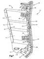
- FIG. 7is a perspective view of a side of the cover of FIG. 2 ;
- FIG. 8is an enlarged view illustrating a portion of the cover during rupturing of the rupturable portion
- FIG. 9is a side view of the cover and illustrates the deployment door portion in an open condition.
- FIG. 1illustrates a vehicle occupant protection apparatus 10 constructed in accordance with the present invention.
- the vehicle occupant protection apparatus 10 of FIG. 1is a passenger side air bag module that is mounted in an instrument panel 12 of a vehicle 14 .
- the air bag module 10 of FIG. 1includes an air bag 18 .
- the air bag 18when in a stored condition, is located in an air bag housing 20 .
- the air bag housing 20 of FIG. 1is a reaction canister that is mounted in the instrument panel 12 of the vehicle 14 .
- the reaction canister 20includes a deployment opening 22 through which the air bag 18 is inflatable. In FIG. 1 , the reaction canister 20 supports the air bag 18 .
- the air bag module 10also includes an inflation fluid source.
- the inflation fluid source illustrated in FIG. 1is an inflator 26 that is actuatable for providing inflation fluid.
- the inflator 26may be any convention type of inflator that is actuatable for providing inflation fluid.
- the inflator 26 of FIG. 1is located in the reaction canister 20 and is supported by the reaction canister.
- the air bag 18receives the inflation fluid provided by actuation of the inflator 26 . In response to receiving inflation fluid, the air bag 18 inflates through the deployment opening 22 in the reaction canister 20 and in a direction outward of the instrument panel 12 .
- the air bag module 10also includes a cover 30 for covering the deployment opening 22 of the reaction canister 20 .
- the cover 30includes a rupturable portion that is ruptured by the inflating air bag 18 for enabling the air bag to exit the reaction canister 20 through the deployment opening 22 .
- the cover 30includes an attachment portion 34 and a deployment door portion 36 .
- the attachment portion 34is generally rectangular in shape and includes an upper wall 40 , a lower wall 42 , and opposite inboard and outboard side walls 44 and 46 , respectively.
- a generally rectangular passage that forms a chute for the inflating air bagextends through the attachment portion 34 .
- the upper and lower walls 40 and 42extend parallel to one another and are spaced apart by the inboard and outboard side walls 44 and 46 . While the drawings show that the upper and lower walls extend parallel, such is not necessary in all constructions through out the extent of the walls.
- the upper wall 40has a length, measured longitudinally between a front edge (not shown), to which the deployment door portion 36 is attached, and a rear edge 50 of the attachment portion 34 that is approximately fifty percent longer than the lower wall 42 . This is true of the construction shown, but is not a requirement for practicing the invention.
- the through holes 54extend through the upper and lower walls 40 and 42 .
- the through holes 54are spaced laterally apart from one another and are spaced equidistance from one another.
- the through-holes 54are sized for receiving locking members (not shown) located on the reaction canister 20 for securing the cover 30 to the reaction canister.
- the material thickness of the upper and lower walls 40 and 42is increased between the through-holes 54 and the rear edge 50 of the attachment portion.
- the increased material thicknessprovides for increased strength of the upper and lower walls 40 and 42 between the through-holes 54 and the rear edge 50 .
- the upper and lower walls 40 and 42have generally planar exterior surfaces 58 and 60 ( FIG. 5 ), respectively.
- the increased material thicknessforms undulations 62 ( FIG. 3 ) on the interior surfaces of the upper and lower walls 40 and 42 .
- the inboard and outboard side walls 44 and 46connect opposite ends of the upper and lower walls 40 and 42 .
- the outboard side wall 46is generally planar and extends generally perpendicular to the upper and lower walls 40 and 42 .
- the inboard wall 44includes an upper section 70 , a central section 72 , and a lower section 74 .
- the upper and lower sections 70 and 74 of the inboard side wall 44extend parallel to one another.
- the central section 72tapers outward, i.e., away from the outboard side wall 46 , as it extends between the upper and lower sections 70 and 74 .
- the lower section 74 of the inboard side wall 44is spaced away from the outboard side wall 46 by a slightly larger distance than the upper section 70 .
- Two locking tabs 80are formed on an external surface of the inboard side wall 44 .
- One locking tab 80is located in the upper section 70 of the inboard side wall 44 adjacent a front edge 84 ( FIG. 7 ) of the inboard sidewall.
- the other locking tab 80is located in the lower section 74 of the inboard side wall 44 adjacent the front edge 84 .
- the locking tabs 80are adapted to interlock with portions of the instrument panel 12 for securing the cover 30 relative to the instrument panel.
- the deployment door portion 36 of the cover 30may be a single piece door, with or without a coating of paint, and not formed from separate structures secured together or may include separate structures secured together.
- the drawingsillustrate a door portion 36 that includes inner and outer members 90 and 92 ( FIG. 4 ) that are vibration welded together.
- a single member deployment door portionmay be used.
- the inner member 90 of the deployment door portion 36is formed integrally with the attachment portion 34 and not from separate structures secured together.
- the attachment portion 34 and the inner member 90 of the deployment door portion 36are injected molded in a single shot injection molding machine.
- the inner member 90 of the deployment door portion 36includes an upper door portion 96 and a lower door portion 98 .
- a horizontally extending gap 100( FIG. 6 ) extends across the inner member 90 and separates the upper and lower door portions 96 and 98 .
- the upper door portion 96is attached to the front edge of the upper wall 40 of the attachment portion 34 and to the front edges, only front edge 84 shown, of the uppermost halves of the inboard and outboard side walls 44 and 46 .
- the upper door portion 96includes an exterior surface 104 ( FIG. 4 ) and an interior surface 106 ( FIG. 3 ).
- ribs 108extend outwardly of the exterior surface 104 of the upper door portion 96 .
- Two horizontal ribs 110( FIGS. 5 , 7 , and 9 ) extend laterally across the interior surface 106 of the upper door portion 96 from a location adjacent the inboard side wall 44 to a location adjacent the outboard side wall 46 .
- the horizontal ribs 110act as hinge line/relief between the two vibration welded door parts 90 , 92 .
- Multiple locking members 112extend outwardly of the interior surface 106 of the upper door portion 96 at a location above the upper wall 40 of the attachment portion 34 .
- the locking members 112are spaced laterally away from one another and are adapted to interlock with portions of the instrument panel 12 for securing the cover 30 relative to the instrument panel.
- a single locking member 114extends outwardly of the interior surface 106 of the upper door portion 96 at a location adjacent the outboard side wall 46 of the attachment portion 34 .
- the locking member 114is adapted to interlock with a portion of the instrument panel 12 for securing the cover 30 relative to the instrument panel.
- the lower door portion 98is attached to the front edge of the lower wall 42 of the attachment portion 34 and the front edges, only front edge 84 shown, of the lowermost halves of the inboard and outboard side walls 44 and 46 .
- the lower door portion 98includes an exterior surface 120 ( FIG. 4 ) and an interior surface 122 ( FIG. 3 ). As FIG. 4 illustrates, ribs 124 extend outwardly of the exterior surface 120 of the lower door portion 98 .
- Two horizontal ribs 126( FIGS. 5 , 7 , and 9 ) extend laterally across the interior surface 122 of the lower door portion 98 from a location adjacent the inboard side wall 44 to a location adjacent the outboard side wall 46 .
- the horizontal ribs 126act to provide as hinge line/relief between the two vibration welded door parts 90 , 92 .
- Multiple locking members 128extend outwardly of the interior surface 122 of the lower door portion 98 at a location below the lower wall 42 of the attachment portion 34 .
- the locking members 128are spaced laterally away from one another and are adapted to interlock with portions of the instrument panel 12 for securing the cover 30 relative to the instrument panel.
- a single locking member 130extends outwardly of the interior surface 122 of the lower door portion 98 at a location adjacent the outboard side wall 46 of the attachment portion 34 .
- the locking member 130is adapted to interlock with a portion of the instrument panel 12 for securing the cover 30 relative to the instrument panel.
- FIG. 3is an enlarged view illustrating the tear tabs 140 at the union of the inboard side wall 44 and the upper portion 96 of the inner member 90 .
- the tear tabs 140connect the front edge 84 of the inboard side wall 44 to the interior surfaces 106 and 122 of the upper and lower door portions 96 and 98 , respectively, of the inner member 90 .
- Gaps 142FIG.
- the tear tabs 140 and gaps 142 at the union of the outboard side wall 46 and the inner member 90are similar to those at the union of the inboard side wall 44 and the inner member.
- the outer member 92 of the deployment door portion 36 of the cover 30is generally rectangular and includes interior and exterior surfaces 150 and 152 ( FIG. 6 ), respectively.
- a horizontally extending tear seam 156( FIG. 6 ) extends completely across the outer member 92 .
- the tear seam 156could terminate short of the sides of the member 92 .
- the tear seam 156is formed by a thinned portion of the outer member 92 that is located between a recess 158 formed in the interior surface 150 of the outer member and a style line 160 formed in the exterior surface 152 of the outer member.
- the tear seam 156separates upper and lower door portions 164 and 166 , respectively, of the outer member 92 .
- the upper door portion 164 of the outer member 92is slightly larger than the upper door portion 96 of the inner member 90 of the deployment door portion 36 .
- the lower door portion 166 of the outer member 92is slightly larger than the lower door portion 98 of the inner member 90 .
- a horizontal style line 168( FIG. 4 ) extends across the exterior surface 152 of the upper door portion 164 of the outer member 92 .
- the inner and outer members 90 and 92 of the deployment door portion 36 of the cover 30are vibration welded together.
- the tear seam 156 of the outer member 92aligns with the gap 100 of the inner member 90 , as shown in FIG. 6 .
- the tear seam 156 of the outer member 92 of the deployment door portion 36 and the vertical tear portions 134 and 136 formed at the unions of the inboard and outboard side walls 44 and 46 and the inner member 90collectively form a rupturable portion of the cover 30 .
- the rupturable portion of the cover 30ruptures in response to a force of the inflating air bag 18 acting against the interior surfaces 106 and 122 of the inner member 90 of the deployment door portion 36 .
- the deployment door portion 36 of the cover 30moves from a position closing the deployment opening 22 to an open condition for enabling inflation of the air bag 18 through the cover and outward of the instrument panel 12 .
- FIG. 9illustrates the deployment door portion 36 in an open condition.
- the upper door portions 96 and 164 of the inner and outer members 90 and 92may pivot about the front edge of the upper wall 40 of the attachment portion 34 and the lower portions 98 and 166 of the inner and outer members 90 and 92 , respectively, may pivot about the front edge of the lower wall 42 of the attachment portion.
- the force of the inflating air bag 18 on the interior surfaces 106 and 122 of the inner member 90 of the deployment door portion 36tends to force the upper door portions 96 and 164 of the inner and outer members 90 and 92 , respectively, of the deployment door portion apart from the lower door portions 98 and 166 .
- the tear seam 156 of the outer member 92 of the deployment door portion 36ruptures.
- the rupture of the tear seam 156 of the outer member 92generally begins at a central location and simultaneously extends laterally outward toward inboard and outboard edges of the outer member.
- the force of the inflating air bag 18tends to move the upper door portions 96 and 164 further apart from the lower door portions 98 and 166 .
- the forceruptures the vertical tear portions 134 and 136 located at the unions of the inner member 90 of the deployment door portion 36 and the inboard and outboard side walls 44 and 46 of the attachment portion 34 .
- the vertical tear portions 134 , 136could rupture before, during, or after rupture of the horizontal door portion 36 .
- the tear tabswill tear in a manner that depends upon tear seam location, door shape and bag fold.
- the tear tabs 140 located closest to the ruptured tear seam 156are stretched.
- the stretching of the tear tabs 140causes the tear tabs to rupture, as shown with reference to FIG. 8 .
- the tear tabs 140are ruptured sequentially beginning with the tear tabs located closest to the tear seam 156 and ending with the tear tabs located farthest from the tear seam. The rupturing of the tear tabs 140 enables the deployment door portion 36 to move from a position closing the deployment opening 22 to the open condition illustrated in FIG. 9 .
- the tear tabs 140 of the illustrated embodimenthave generally square cross-sectional shapes.
- the illustrated tear tabs 140also have a generally uniform material thickness along a length of the tear tabs.
- the tear tabs 140may have any cross-sectional shape and may have a varying material thickness.
- the tear tabsmay be cylindrical and may include thinned portions that defines locations at which the tear tabs rupture. Additionally, the material properties of the tear tabs and the shape of the tear tabs may be adjusted for controlling the force necessary for rupturing the tear tabs.
Landscapes
- Engineering & Computer Science (AREA)
- Mechanical Engineering (AREA)
- Air Bags (AREA)
- Instrument Panels (AREA)
Abstract
Description
Claims (13)
Priority Applications (2)
| Application Number | Priority Date | Filing Date | Title |
|---|---|---|---|
| US11/218,121US7695001B2 (en) | 2005-09-01 | 2005-09-01 | Vehicle protection apparatus with cover having a rupturable portion with tear tabs |
| JP2006237323AJP4516056B2 (en) | 2005-09-01 | 2006-09-01 | Vehicle protection device with a cover having a rupturable part including a tear-off tab |
Applications Claiming Priority (1)
| Application Number | Priority Date | Filing Date | Title |
|---|---|---|---|
| US11/218,121US7695001B2 (en) | 2005-09-01 | 2005-09-01 | Vehicle protection apparatus with cover having a rupturable portion with tear tabs |
Publications (2)
| Publication Number | Publication Date |
|---|---|
| US20070045995A1 US20070045995A1 (en) | 2007-03-01 |
| US7695001B2true US7695001B2 (en) | 2010-04-13 |
Family
ID=37803035
Family Applications (1)
| Application Number | Title | Priority Date | Filing Date |
|---|---|---|---|
| US11/218,121Expired - Fee RelatedUS7695001B2 (en) | 2005-09-01 | 2005-09-01 | Vehicle protection apparatus with cover having a rupturable portion with tear tabs |
Country Status (2)
| Country | Link |
|---|---|
| US (1) | US7695001B2 (en) |
| JP (1) | JP4516056B2 (en) |
Cited By (5)
| Publication number | Priority date | Publication date | Assignee | Title |
|---|---|---|---|---|
| US20090174213A1 (en)* | 2008-01-09 | 2009-07-09 | Toyota Motor Engineering & Manufacturing North America, Inc. | Instrument panel covers with lockout ribs |
| US20100019474A1 (en)* | 2008-07-22 | 2010-01-28 | Kasai Kogyo Co. Ltd. | Vehicle interior parts |
| US20100117337A1 (en)* | 2008-11-12 | 2010-05-13 | Toyoda Gosei Co., Ltd. | Front passenger seat airbag apparatus |
| US8585078B1 (en)* | 2013-03-13 | 2013-11-19 | Autoliv Asp, Inc. | Tear seams for inflatable airbag covers |
| US8870219B1 (en) | 2013-08-02 | 2014-10-28 | Faurecia Interior Systems, Inc. | Foam-in-place interior panels having integrated airbag doors including substrates with airbag chute-door assemblies for motor vehicles |
Families Citing this family (7)
| Publication number | Priority date | Publication date | Assignee | Title |
|---|---|---|---|---|
| US7695001B2 (en)* | 2005-09-01 | 2010-04-13 | Trw Vehicle Safety Systems Inc. | Vehicle protection apparatus with cover having a rupturable portion with tear tabs |
| US7789416B2 (en)* | 2005-09-08 | 2010-09-07 | Honda Motor Co., Ltd. | Air bag module cover structure |
| US20070187930A1 (en)* | 2006-02-16 | 2007-08-16 | Ravi Kiran Chitteti | Automotive structures with hidden airbag door and integrated airbag chute |
| US7891702B2 (en)* | 2008-03-27 | 2011-02-22 | Intertec Systems, Llc | Apparatus and method for attaching passenger side inflatable restraint chute |
| US7784820B2 (en) | 2008-11-04 | 2010-08-31 | Automotive Components Holdings, Llc | Air bag deployment chute |
| CN106347129B (en)* | 2016-08-31 | 2019-05-07 | 重庆长安汽车股份有限公司 | A kind of installation position limiting structure of accessory instrument panel body and rear-end plate |
| KR20210000908A (en)* | 2019-06-26 | 2021-01-06 | 현대모비스 주식회사 | Cover device of airbag |
Citations (37)
| Publication number | Priority date | Publication date | Assignee | Title |
|---|---|---|---|---|
| US4903986A (en)* | 1988-11-14 | 1990-02-27 | General Motors Corporation | Modular occupant restraint system |
| US5062663A (en)* | 1989-09-25 | 1991-11-05 | Takata Corporation | Module cover of air bag system |
| US5096220A (en)* | 1989-12-14 | 1992-03-17 | Takata Corporation | Cover for air bag system |
| JPH04163255A (en)* | 1990-10-26 | 1992-06-08 | Takata Kk | Module cover for air bag device |
| US5303951A (en)* | 1992-10-30 | 1994-04-19 | Allied-Signal Inc. | Air bag assembly with housing and fastenerless deployment door |
| US5342090A (en)* | 1992-10-30 | 1994-08-30 | Alliedsignal Inc. | Passenger air bag module with means for retaining an air bag deployment door to a housing |
| US5354093A (en)* | 1993-04-05 | 1994-10-11 | General Motors Corporation | Air bag module having integral cover attachment |
| US5435594A (en)* | 1993-12-03 | 1995-07-25 | Trw Inc. | Dual air bag system for occupant restraint |
| US5445409A (en)* | 1994-10-17 | 1995-08-29 | General Motors Corporation | Passenger airbag snap-on deployment door |
| US5470097A (en)* | 1993-09-03 | 1995-11-28 | Morton International, Inc. | Closure for air bag installation |
| US5709402A (en)* | 1996-07-29 | 1998-01-20 | Morton International, Inc. | Attachment fingers for airbag module cover |
| US5794967A (en)* | 1996-08-02 | 1998-08-18 | Alliedsignal Inc. | Passenger air bag module with means for retaining an air bag deployment door to a housing |
| US5845931A (en)* | 1998-01-09 | 1998-12-08 | Textron Automotive Company Inc. | Instrument panel having integrated airbag deployment door |
| US5845929A (en)* | 1994-05-21 | 1998-12-08 | Petri Ag | Covering means for air-bag-collision-safety means as well as process for the production thereof |
| US5904367A (en)* | 1997-07-01 | 1999-05-18 | Chrysler Corporation | Air bag module with floating door attachment |
| JPH11139235A (en) | 1997-09-04 | 1999-05-25 | Toyo Tire & Rubber Co Ltd | Air bag door for air bag device |
| US6126191A (en)* | 1998-03-16 | 2000-10-03 | General Motors Corporation | Air bag module assembly |
| US20010002749A1 (en)* | 1999-12-06 | 2001-06-07 | Hironori Usami | Case of air bag system |
| US6296270B1 (en)* | 1999-10-01 | 2001-10-02 | Takata Corporation | Airbag device with lid connection mechanism |
| US6325407B1 (en)* | 1999-10-18 | 2001-12-04 | Autoliv Asp, Inc. | Airbag module cover attachment |
| US6341796B1 (en)* | 2001-02-02 | 2002-01-29 | Patent Holding Company | Air bag cover with a non-exposed tear seam |
| US6467801B1 (en)* | 2001-06-20 | 2002-10-22 | Patent Holding Company | Air bag deployment chute and panel assembly |
| US6581958B2 (en)* | 2001-04-17 | 2003-06-24 | Autoliv Asp, Inc. | Energy managed airbag cover |
| US6588794B1 (en)* | 1999-10-29 | 2003-07-08 | Trw Automotive Safety Systems Gmbh & Co. Kg | Method for manufacturing a cover cap for a gas bag restraint module and cover cap |
| US6789816B2 (en)* | 2002-12-06 | 2004-09-14 | Daimlerchrysler Corporation | Passenger airbag assembly |
| US20040188986A1 (en)* | 2003-03-31 | 2004-09-30 | Rogers Dennis R. | Airbag module door assembly |
| US20050212268A1 (en)* | 2004-03-23 | 2005-09-29 | Trw Automative Gmbh | Cover arrangment for a gas bag module |
| US20050263988A1 (en)* | 2004-05-28 | 2005-12-01 | Richard Welford | Driver side airbag module assembly |
| US20060038385A1 (en)* | 2004-08-20 | 2006-02-23 | Eric Baumbach | Air bag door and attachment method |
| US7052036B2 (en)* | 2002-09-05 | 2006-05-30 | Hyundai Mobis Co., Ltd. | Passenger airbag module for a motor vehicle |
| US20060220351A1 (en)* | 2005-03-31 | 2006-10-05 | Takata Restraint Systems, Inc. | Base plate attachment |
| US7121577B2 (en)* | 2002-06-24 | 2006-10-17 | Delphi Technologies, Inc. | Cover for airbag module and method of making |
| US20070007754A1 (en)* | 2005-07-11 | 2007-01-11 | Rybinski Anthony V | Air bag chute |
| US20070018434A1 (en)* | 2005-07-19 | 2007-01-25 | Takata Corporation | Airbag apparatus cover and airbag apparatus |
| US20070029763A1 (en)* | 2005-08-03 | 2007-02-08 | Takata Corporation | Airbag-device cover and airbag device |
| US20070045994A1 (en)* | 2005-08-25 | 2007-03-01 | New Venture Holdings, Llc | Air bag cover assembly including an air bag deployment concentrator and at least one integrally hinged air bag door |
| US20070045995A1 (en)* | 2005-09-01 | 2007-03-01 | Trw Vehicle Safety Systems Inc. | Vehicle protection apparatus with cover having a rupturable portion with tear tabs |
- 2005
- 2005-09-01USUS11/218,121patent/US7695001B2/ennot_activeExpired - Fee Related
- 2006
- 2006-09-01JPJP2006237323Apatent/JP4516056B2/enactiveActive
Patent Citations (38)
| Publication number | Priority date | Publication date | Assignee | Title |
|---|---|---|---|---|
| US4903986A (en)* | 1988-11-14 | 1990-02-27 | General Motors Corporation | Modular occupant restraint system |
| US5062663A (en)* | 1989-09-25 | 1991-11-05 | Takata Corporation | Module cover of air bag system |
| US5096220A (en)* | 1989-12-14 | 1992-03-17 | Takata Corporation | Cover for air bag system |
| JPH04163255A (en)* | 1990-10-26 | 1992-06-08 | Takata Kk | Module cover for air bag device |
| US5303951A (en)* | 1992-10-30 | 1994-04-19 | Allied-Signal Inc. | Air bag assembly with housing and fastenerless deployment door |
| US5342090A (en)* | 1992-10-30 | 1994-08-30 | Alliedsignal Inc. | Passenger air bag module with means for retaining an air bag deployment door to a housing |
| US5354093A (en)* | 1993-04-05 | 1994-10-11 | General Motors Corporation | Air bag module having integral cover attachment |
| US5470097A (en)* | 1993-09-03 | 1995-11-28 | Morton International, Inc. | Closure for air bag installation |
| US5435594A (en)* | 1993-12-03 | 1995-07-25 | Trw Inc. | Dual air bag system for occupant restraint |
| US5845929A (en)* | 1994-05-21 | 1998-12-08 | Petri Ag | Covering means for air-bag-collision-safety means as well as process for the production thereof |
| US5445409A (en)* | 1994-10-17 | 1995-08-29 | General Motors Corporation | Passenger airbag snap-on deployment door |
| US5709402A (en)* | 1996-07-29 | 1998-01-20 | Morton International, Inc. | Attachment fingers for airbag module cover |
| US5794967A (en)* | 1996-08-02 | 1998-08-18 | Alliedsignal Inc. | Passenger air bag module with means for retaining an air bag deployment door to a housing |
| US5904367A (en)* | 1997-07-01 | 1999-05-18 | Chrysler Corporation | Air bag module with floating door attachment |
| JPH11139235A (en) | 1997-09-04 | 1999-05-25 | Toyo Tire & Rubber Co Ltd | Air bag door for air bag device |
| US5845931A (en)* | 1998-01-09 | 1998-12-08 | Textron Automotive Company Inc. | Instrument panel having integrated airbag deployment door |
| US6126191A (en)* | 1998-03-16 | 2000-10-03 | General Motors Corporation | Air bag module assembly |
| US6296270B1 (en)* | 1999-10-01 | 2001-10-02 | Takata Corporation | Airbag device with lid connection mechanism |
| US6325407B1 (en)* | 1999-10-18 | 2001-12-04 | Autoliv Asp, Inc. | Airbag module cover attachment |
| US6588794B1 (en)* | 1999-10-29 | 2003-07-08 | Trw Automotive Safety Systems Gmbh & Co. Kg | Method for manufacturing a cover cap for a gas bag restraint module and cover cap |
| US20010002749A1 (en)* | 1999-12-06 | 2001-06-07 | Hironori Usami | Case of air bag system |
| US6341796B1 (en)* | 2001-02-02 | 2002-01-29 | Patent Holding Company | Air bag cover with a non-exposed tear seam |
| US6581958B2 (en)* | 2001-04-17 | 2003-06-24 | Autoliv Asp, Inc. | Energy managed airbag cover |
| US6467801B1 (en)* | 2001-06-20 | 2002-10-22 | Patent Holding Company | Air bag deployment chute and panel assembly |
| US7121577B2 (en)* | 2002-06-24 | 2006-10-17 | Delphi Technologies, Inc. | Cover for airbag module and method of making |
| US7052036B2 (en)* | 2002-09-05 | 2006-05-30 | Hyundai Mobis Co., Ltd. | Passenger airbag module for a motor vehicle |
| US6789816B2 (en)* | 2002-12-06 | 2004-09-14 | Daimlerchrysler Corporation | Passenger airbag assembly |
| US20040188986A1 (en)* | 2003-03-31 | 2004-09-30 | Rogers Dennis R. | Airbag module door assembly |
| US7073817B2 (en)* | 2003-03-31 | 2006-07-11 | Tk Holdings, Inc. | Airbag module door assembly |
| US20050212268A1 (en)* | 2004-03-23 | 2005-09-29 | Trw Automative Gmbh | Cover arrangment for a gas bag module |
| US20050263988A1 (en)* | 2004-05-28 | 2005-12-01 | Richard Welford | Driver side airbag module assembly |
| US20060038385A1 (en)* | 2004-08-20 | 2006-02-23 | Eric Baumbach | Air bag door and attachment method |
| US20060220351A1 (en)* | 2005-03-31 | 2006-10-05 | Takata Restraint Systems, Inc. | Base plate attachment |
| US20070007754A1 (en)* | 2005-07-11 | 2007-01-11 | Rybinski Anthony V | Air bag chute |
| US20070018434A1 (en)* | 2005-07-19 | 2007-01-25 | Takata Corporation | Airbag apparatus cover and airbag apparatus |
| US20070029763A1 (en)* | 2005-08-03 | 2007-02-08 | Takata Corporation | Airbag-device cover and airbag device |
| US20070045994A1 (en)* | 2005-08-25 | 2007-03-01 | New Venture Holdings, Llc | Air bag cover assembly including an air bag deployment concentrator and at least one integrally hinged air bag door |
| US20070045995A1 (en)* | 2005-09-01 | 2007-03-01 | Trw Vehicle Safety Systems Inc. | Vehicle protection apparatus with cover having a rupturable portion with tear tabs |
Cited By (11)
| Publication number | Priority date | Publication date | Assignee | Title |
|---|---|---|---|---|
| US20090174213A1 (en)* | 2008-01-09 | 2009-07-09 | Toyota Motor Engineering & Manufacturing North America, Inc. | Instrument panel covers with lockout ribs |
| US7819456B2 (en)* | 2008-01-09 | 2010-10-26 | Toyota Motor Engineering & Manufacturing North America, Inc. | Instrument panel covers with lockout ribs |
| US20100019474A1 (en)* | 2008-07-22 | 2010-01-28 | Kasai Kogyo Co. Ltd. | Vehicle interior parts |
| US7874577B2 (en)* | 2008-07-22 | 2011-01-25 | Kasai Kogyo, Co., Ltd. | Vehicle interior parts |
| US20100117337A1 (en)* | 2008-11-12 | 2010-05-13 | Toyoda Gosei Co., Ltd. | Front passenger seat airbag apparatus |
| US7980586B2 (en)* | 2008-11-12 | 2011-07-19 | Toyoda Gosei Co., Ltd. | Front passenger seat airbag apparatus |
| US8585078B1 (en)* | 2013-03-13 | 2013-11-19 | Autoliv Asp, Inc. | Tear seams for inflatable airbag covers |
| US8870219B1 (en) | 2013-08-02 | 2014-10-28 | Faurecia Interior Systems, Inc. | Foam-in-place interior panels having integrated airbag doors including substrates with airbag chute-door assemblies for motor vehicles |
| US8931798B1 (en) | 2013-08-02 | 2015-01-13 | Faurecia Interior Systems, Inc. | Foam-in-place interior panels having integrated airbag doors including substrates with airbag chute-door assemblies for motor vehicles |
| US20150035260A1 (en)* | 2013-08-02 | 2015-02-05 | Faurecia Interior Systems, Inc. | Foam-in-place interior panels having integrated airbag doors including substrates with airbag chute-door assemblies for motor vehicles |
| US9102298B2 (en)* | 2013-08-02 | 2015-08-11 | Faurecia Interior Systems, Inc. | Foam-in-place interior panels having integrated airbag doors including substrates with airbag chute-door assemblies for motor vehicles |
Also Published As
| Publication number | Publication date |
|---|---|
| US20070045995A1 (en) | 2007-03-01 |
| JP2007062730A (en) | 2007-03-15 |
| JP4516056B2 (en) | 2010-08-04 |
Similar Documents
| Publication | Publication Date | Title |
|---|---|---|
| JP4516056B2 (en) | Vehicle protection device with a cover having a rupturable part including a tear-off tab | |
| US7185912B2 (en) | Knee protection airbag device | |
| JP3188254B2 (en) | Car safety equipment | |
| US6874810B2 (en) | Airbag cover deployment flaps | |
| US7549671B2 (en) | Knee-protecting airbag apparatus | |
| US5456487A (en) | Passenger air bag door | |
| US7744115B2 (en) | Airbag-releasing structure, inner case, and airbag device | |
| US6695339B2 (en) | Vehicle occupant protection device | |
| CN101198491A (en) | Interior panel assembly and airbag device | |
| US6655711B1 (en) | Air bag cover assembly | |
| US7988184B2 (en) | Front passenger airbag device | |
| US9975514B1 (en) | Automotive air bag chute door hinge with variable extension | |
| US8414024B1 (en) | Blow-molded active side bolster with tear tabs | |
| US10625702B2 (en) | Closing device for a housing for an airbag | |
| US7290790B2 (en) | Airbag chute assembly | |
| US5738366A (en) | Chute structure for an inflatable vehicle occupant restraint | |
| JPH06321044A (en) | Elastic cover for air bag device | |
| JP3039857U (en) | Closure element for airbag deployment opening | |
| JP2955698B2 (en) | Inflatable airbag module | |
| JP4446901B2 (en) | Cover for airbag device and airbag device | |
| CZ164793A3 (en) | Hidden door system for auxiliary inflatable safety device | |
| US20110148079A1 (en) | Automotive psir with unscored cover | |
| JP2006205889A5 (en) | ||
| US5957484A (en) | Airbag tear seam | |
| JP2013123974A (en) | Module cover and airbag device |
Legal Events
| Date | Code | Title | Description |
|---|---|---|---|
| AS | Assignment | Owner name:TRW VEHICLE SAFETY SYSTEMS INC.,MICHIGAN Free format text:ASSIGNMENT OF ASSIGNORS INTEREST;ASSIGNORS:ADLER, ANGELO;DEBBS, ROBERT R.;REEL/FRAME:016936/0403 Effective date:20050830 Owner name:TRW VEHICLE SAFETY SYSTEMS INC., MICHIGAN Free format text:ASSIGNMENT OF ASSIGNORS INTEREST;ASSIGNORS:ADLER, ANGELO;DEBBS, ROBERT R.;REEL/FRAME:016936/0403 Effective date:20050830 | |
| FEPP | Fee payment procedure | Free format text:PAYER NUMBER DE-ASSIGNED (ORIGINAL EVENT CODE: RMPN); ENTITY STATUS OF PATENT OWNER: LARGE ENTITY Free format text:PAYOR NUMBER ASSIGNED (ORIGINAL EVENT CODE: ASPN); ENTITY STATUS OF PATENT OWNER: LARGE ENTITY | |
| STCF | Information on status: patent grant | Free format text:PATENTED CASE | |
| AS | Assignment | Owner name:JPMORGAN CHASE BANK, N.A., AS COLLATERAL AGENT, NE Free format text:SECURITY AGREEMENT;ASSIGNORS:TRW VEHICLE SAFETY SYSTEMS INC.;TRW AUTOMOTIVE U.S. LLC;KELSEY-HAYES COMPANY;REEL/FRAME:029529/0534 Effective date:20120928 | |
| FPAY | Fee payment | Year of fee payment:4 | |
| AS | Assignment | Owner name:TRW VEHICLE SAFETY SYSTEMS INC., MICHIGAN Free format text:RELEASE OF SECURITY INTEREST;ASSIGNOR:JPMORGAN CHASE BANK, N.A.;REEL/FRAME:031645/0697 Effective date:20131028 Owner name:KELSEY-HAYES COMPANY, MICHIGAN Free format text:RELEASE OF SECURITY INTEREST;ASSIGNOR:JPMORGAN CHASE BANK, N.A.;REEL/FRAME:031645/0697 Effective date:20131028 Owner name:TRW AUTOMOTIVE U.S. LLC, MICHIGAN Free format text:RELEASE OF SECURITY INTEREST;ASSIGNOR:JPMORGAN CHASE BANK, N.A.;REEL/FRAME:031645/0697 Effective date:20131028 Owner name:TRW INTELLECTUAL PROPERTY CORP., MICHIGAN Free format text:RELEASE OF SECURITY INTEREST;ASSIGNOR:JPMORGAN CHASE BANK, N.A.;REEL/FRAME:031645/0697 Effective date:20131028 | |
| MAFP | Maintenance fee payment | Free format text:PAYMENT OF MAINTENANCE FEE, 8TH YEAR, LARGE ENTITY (ORIGINAL EVENT CODE: M1552) Year of fee payment:8 | |
| FEPP | Fee payment procedure | Free format text:MAINTENANCE FEE REMINDER MAILED (ORIGINAL EVENT CODE: REM.); ENTITY STATUS OF PATENT OWNER: LARGE ENTITY | |
| LAPS | Lapse for failure to pay maintenance fees | Free format text:PATENT EXPIRED FOR FAILURE TO PAY MAINTENANCE FEES (ORIGINAL EVENT CODE: EXP.); ENTITY STATUS OF PATENT OWNER: LARGE ENTITY | |
| STCH | Information on status: patent discontinuation | Free format text:PATENT EXPIRED DUE TO NONPAYMENT OF MAINTENANCE FEES UNDER 37 CFR 1.362 | |
| FP | Lapsed due to failure to pay maintenance fee | Effective date:20220413 |