US7693654B1 - Method for mapping spaces with respect to a universal uniform spatial reference - Google Patents
Method for mapping spaces with respect to a universal uniform spatial referenceDownload PDFInfo
- Publication number
- US7693654B1 US7693654B1US11/603,242US60324206AUS7693654B1US 7693654 B1US7693654 B1US 7693654B1US 60324206 AUS60324206 AUS 60324206AUS 7693654 B1US7693654 B1US 7693654B1
- Authority
- US
- United States
- Prior art keywords
- marker
- location
- sensor
- mapping
- reference frame
- Prior art date
- Legal status (The legal status is an assumption and is not a legal conclusion. Google has not performed a legal analysis and makes no representation as to the accuracy of the status listed.)
- Active, expires
Links
- 238000013507mappingMethods0.000titleclaimsabstractdescription92
- 238000000034methodMethods0.000titleclaimsabstractdescription63
- 239000003550markerSubstances0.000claimsdescription56
- 230000001131transforming effectEffects0.000claimsdescription5
- 230000000977initiatory effectEffects0.000claims1
- 238000005259measurementMethods0.000description12
- 238000013480data collectionMethods0.000description11
- 230000033001locomotionEffects0.000description9
- 230000009466transformationEffects0.000description9
- 238000004891communicationMethods0.000description5
- 230000008569processEffects0.000description4
- 230000000007visual effectEffects0.000description3
- 238000004364calculation methodMethods0.000description2
- 238000012986modificationMethods0.000description2
- 230000004048modificationEffects0.000description2
- XUIMIQQOPSSXEZ-UHFFFAOYSA-NSiliconChemical compound[Si]XUIMIQQOPSSXEZ-UHFFFAOYSA-N0.000description1
- 230000003213activating effectEffects0.000description1
- 230000004913activationEffects0.000description1
- 238000007792additionMethods0.000description1
- 238000013459approachMethods0.000description1
- 230000005540biological transmissionEffects0.000description1
- 238000006243chemical reactionMethods0.000description1
- 239000003795chemical substances by applicationSubstances0.000description1
- 230000002596correlated effectEffects0.000description1
- 230000001186cumulative effectEffects0.000description1
- 125000004122cyclic groupChemical group0.000description1
- 238000010586diagramMethods0.000description1
- 230000005183environmental healthEffects0.000description1
- 238000001914filtrationMethods0.000description1
- 238000003384imaging methodMethods0.000description1
- 230000010354integrationEffects0.000description1
- 230000004807localizationEffects0.000description1
- 230000006855networkingEffects0.000description1
- 238000012545processingMethods0.000description1
- 230000005855radiationEffects0.000description1
- 238000007634remodelingMethods0.000description1
- 238000011160researchMethods0.000description1
- 230000004044responseEffects0.000description1
- 229910052710siliconInorganic materials0.000description1
- 239000010703siliconSubstances0.000description1
- 230000005236sound signalEffects0.000description1
- 238000012876topographyMethods0.000description1
Images


Classifications
- G—PHYSICS
- G01—MEASURING; TESTING
- G01C—MEASURING DISTANCES, LEVELS OR BEARINGS; SURVEYING; NAVIGATION; GYROSCOPIC INSTRUMENTS; PHOTOGRAMMETRY OR VIDEOGRAMMETRY
- G01C21/00—Navigation; Navigational instruments not provided for in groups G01C1/00 - G01C19/00
- G01C21/20—Instruments for performing navigational calculations
- G—PHYSICS
- G05—CONTROLLING; REGULATING
- G05D—SYSTEMS FOR CONTROLLING OR REGULATING NON-ELECTRIC VARIABLES
- G05D1/00—Control of position, course, altitude or attitude of land, water, air or space vehicles, e.g. using automatic pilots
- G05D1/02—Control of position or course in two dimensions
- G05D1/021—Control of position or course in two dimensions specially adapted to land vehicles
- G05D1/0231—Control of position or course in two dimensions specially adapted to land vehicles using optical position detecting means
- G05D1/0238—Control of position or course in two dimensions specially adapted to land vehicles using optical position detecting means using obstacle or wall sensors
- G05D1/024—Control of position or course in two dimensions specially adapted to land vehicles using optical position detecting means using obstacle or wall sensors in combination with a laser
- G—PHYSICS
- G05—CONTROLLING; REGULATING
- G05D—SYSTEMS FOR CONTROLLING OR REGULATING NON-ELECTRIC VARIABLES
- G05D1/00—Control of position, course, altitude or attitude of land, water, air or space vehicles, e.g. using automatic pilots
- G05D1/02—Control of position or course in two dimensions
- G05D1/021—Control of position or course in two dimensions specially adapted to land vehicles
- G05D1/0268—Control of position or course in two dimensions specially adapted to land vehicles using internal positioning means
- G05D1/0272—Control of position or course in two dimensions specially adapted to land vehicles using internal positioning means comprising means for registering the travel distance, e.g. revolutions of wheels
- G—PHYSICS
- G05—CONTROLLING; REGULATING
- G05D—SYSTEMS FOR CONTROLLING OR REGULATING NON-ELECTRIC VARIABLES
- G05D1/00—Control of position, course, altitude or attitude of land, water, air or space vehicles, e.g. using automatic pilots
- G05D1/02—Control of position or course in two dimensions
- G05D1/021—Control of position or course in two dimensions specially adapted to land vehicles
- G05D1/0268—Control of position or course in two dimensions specially adapted to land vehicles using internal positioning means
- G05D1/0274—Control of position or course in two dimensions specially adapted to land vehicles using internal positioning means using mapping information stored in a memory device
- G—PHYSICS
- G05—CONTROLLING; REGULATING
- G05D—SYSTEMS FOR CONTROLLING OR REGULATING NON-ELECTRIC VARIABLES
- G05D1/00—Control of position, course, altitude or attitude of land, water, air or space vehicles, e.g. using automatic pilots
- G05D1/02—Control of position or course in two dimensions
- G05D1/021—Control of position or course in two dimensions specially adapted to land vehicles
- G05D1/0231—Control of position or course in two dimensions specially adapted to land vehicles using optical position detecting means
- G05D1/0234—Control of position or course in two dimensions specially adapted to land vehicles using optical position detecting means using optical markers or beacons
- G—PHYSICS
- G05—CONTROLLING; REGULATING
- G05D—SYSTEMS FOR CONTROLLING OR REGULATING NON-ELECTRIC VARIABLES
- G05D1/00—Control of position, course, altitude or attitude of land, water, air or space vehicles, e.g. using automatic pilots
- G05D1/02—Control of position or course in two dimensions
- G05D1/021—Control of position or course in two dimensions specially adapted to land vehicles
- G05D1/0259—Control of position or course in two dimensions specially adapted to land vehicles using magnetic or electromagnetic means
- G05D1/0261—Control of position or course in two dimensions specially adapted to land vehicles using magnetic or electromagnetic means using magnetic plots
Definitions
- GISGlobal Information System
- Datainclude Earth topography and vegetation, as mostly gathered by satellite imagery.
- Other Featuressuch as the centerline of a road, are gathered by driving a vehicle with a GPS (Global Positioning System) system and noting the location of intersections and waypoints.
- Utility locationsare input by surveying with GPS. Collected into GIS databases, the data subsequently are used for vehicle navigation, building operations, emergency response, environmental health, and a wide variety of other applications.
- Maps referenced to the GISare the most efficient, seamless means for indoor and outdoor navigation by military and other robots.
- GPScurrently is not pervasive. It is not available indoors or wherever GPS satellite signals are blocked or weak, such as in areas with heavy forestation or in dense urban areas such as older sections of European and Asian cities. While methods exist that estimate and extrapolate GPS coordinates through signal-less spaces, these result in significant errors in GPS-poor outdoor regions.
- GPSis not used, so few up-to-date, automated “as-built” building interior floor plans exist, globally positioned or not. Instead, if a Map of a building exists at all, it typically is a vector-based CAD drawing by the designing architect. Since buildings rarely are built exactly as specified by the architect, the CAD drawing of the interior spaces usually does not even fit the building's actual exterior footprint. Remodeling and additions, both interior and exterior, rarely get included in the Map.
- mapping techniquesexist, including for example, those described in U.S. Pat. No. 6,009,359 to El-Hakim et al.
- the inventionrelates to a method of model generation and, more particularly, to a method of generating three-dimensional maps from range and intensity images created from by an imaging device and dead reckoning.
- This methodrequires enormous amounts of computer processing, which slows results.
- visual pattern-matching techniquesare not exact, so inaccuracies result.
- the maps generatedare not related to GIS coordinate systems, so the resulting map is not usable within a GIS context. By this method, data gathered without GPS coordinates cannot be spatially associated.
- the present inventioninvolves the generation or making of maps in a universal uniform spatial reference frame.
- the inventioncan generate maps in GIS space (i.e., using GPS coordinates) for spaces that cannot be mapped directly in GIS space because of inadequate reception of positioning signals used in GPS locating schemes.
- a method for generating maps of a desired area that are referenced to a universal uniform spatial reference frameis provided.
- a mobile platform having a mapping processor and at least one mapping sensoris provided.
- the mapping sensoris applied to determine the location of features to be mapped relative to the mobile platform.
- the mobile platformis moved to a new location, and the mapping sensor is further applied to determine the location of features to be mapped relative to the mobile platform, and a map the locations determined is generated or added to.
- These stepsare repeated step until the desired area is mapped.
- the at least one mapping sensoris also applied to locate at least one position on the map of the desired area on a universal uniform spatial reference frame. Positions on the map of the desired area are transformed into the universal uniform spatial reference frame.
- the transformation calculationscan take place concurrently with the data collection, or can take place after.
- a method for generating maps of a desired area that are referenced to a universal uniform spatial reference frameincludes providing a mobile platform having a mapping processor and at least one mapping sensor.
- a markeris provided having a known location in the universal uniform spatial reference frame and the mobile platform is moved to a location within mapping range of the marker.
- the mapping sensoris applied to determine the location of the marker and the location of the marker in the universal uniform spatial reference is communicated to the mobile platform.
- Positions on the map of the desired areaare transformed into the universal uniform spatial reference frame. Again, the transformation calculations can take place concurrently with the data collection, or can take place after.
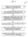
- FIG. 1provides a diagram illustrating a flow of steps in a method according to one embodiment of the invention
- FIG. 2illustrates an autonomous mobile mapping apparatus useful with the invention
- FIG. 3provides an additional view of the autonomous mobile mapping apparatus of FIG. 2 ;
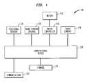
- FIG. 4provides a schematic illustration of elements of the autonomous mobile mapping apparatus of FIG. 2 ;
- FIG. 5illustrates a map generated by the autonomous mobile mapping apparatus of FIG. 2 ;
- FIG. 6illustrates an autonomous mobile mapping apparatus communicating with a satellite positioning system according to one embodiment of the invention
- FIG. 7illustrates an autonomous mobile mapping apparatus obtaining positional information regarding a marker according to one embodiment of the invention
- FIG. 8illustrates an autonomous mobile mapping apparatus obtaining positional information regarding a handheld position receiver according to one embodiment of the invention
- FIG. 9Aillustrates an autonomous mobile mapping apparatus obtaining positional information regarding a number of markers according to one embodiment of the invention.
- FIG. 9Billustrates the autonomous mobile mapping apparatus of FIG. 9A obtaining a second positional information reading regarding the markers of FIG. 9B .
- the universal uniform spatial reference framecan be the GIS, and coordinates on the map can be provided in the format used by the GPS.
- GISrefers to Global Information System, a generic term for a spatial database in which the spatial information is linked to GPS coordinates.
- GPSrefers to the Global Positioning System in which radio systems, typically satellite-based, provide three-dimensional position and time information to which suitably equipped receivers anywhere on or near the surface of the Earth compute their global position, velocity and orientation (heading).
- a mobile platformis provided with a mapping processor and at least one mapping sensor.
- the mapping sensoris then applied 14 to locate features to be mapped relative to the mobile platform.
- a featurerefers to an object within the universal uniform spatial reference frame that may have associated attributes.
- An example of a featuremight be a door.
- Attributesrefer to characteristics of a feature.
- the featureis a door, its attributes might include the manufacturer of the door, the model name or number, the height and width of the door, and whether the door is open or closed.
- Features whose locations are determined by the mapping sensorcan be added to the map.
- the mobile platformcan be moved 16 to a new location, and the mapping sensor applied again to determine the location of other features to be mapped relative to the mobile platform.
- Featurescan again be added to the map.
- the movement and sensor applicationcan be continuous, i.e., the mobile platform may patrol an route or may otherwise be directed on a continuous basis while applying the mapping sensor continuously or the movement and sensor application can be discrete (point to point movement and sensing) or some combination of the two. This movement and sensing step can be repeated 18 until the desired area is fully mapped.
- At least one mapping sensorcan also be applied 20 to locate at least one position on the map on a universal uniform spatial reference frame.
- the mapping sensor or sensorsinclude a GPS receiver so that the mobile platform can track its position in GPS coordinates (and thus in a GIS) as it maps features. If at least part of the area to be mapped includes regions having good reception of satellite signals, this approach may be sufficient. Other ways of locating map positions on the universal uniform spatial reference frame are discussed below.
- Positions on the map of the desired areacan be transformed 22 into coordinates of the universal uniform spatial reference frame based upon the information obtained in step 20 . Once one or more locations on the map are determined in GPS coordinates, all points on the map or that are thereafter mapped can be transformed into GPS coordinates. This transformation can occur in real time during mapping, or map and location information can be batch transformed.
- the mobile platform apparatus used in the methodcan take a variety of physical forms.
- One mobile platform apparatus that could be used with the inventionis the spatial data collection apparatus described in U.S. Pat. No. 6,917,893, filed on Mar. 14, 2003, issued on Jul. 12, 2005, and entitled “Spatial Data Collection Apparatus and Method,” which patent is hereby incorporated by reference in its entirety.
- the mobile platformcan be movable using a handle as is prominently illustrated in the incorporated patent; it can be driven, for example by a joystick; or it can be autonomous using, for example, SLAM techniques (Simultaneous Localization And Mapping, a technique used by an autonomous vehicle to build a map within an unknown environment while at the same time keeping track of its current position).
- SLAM techniquesSimultaneous Localization And Mapping, a technique used by an autonomous vehicle to build a map within an unknown environment while at the same time keeping track of its current position.
- An exemplary autonomous mobile mapping apparatus 110 useful with the inventionincludes a mobile platform 112 and at least one wheel 114 attached to the platform 112 , for example, using hubs.
- the autonomous mobile mapping apparatus 110can also include one or more positional sensors 120 (shown schematically), such as shaft encoders and/or an inertial measurement unit (IMU), for generating the positional data.
- the positional sensors 120could include a GPS receiver for determining the position of the autonomous mobile mapping apparatus in GPS coordinates.
- the autonomous mobile mapping apparatus 110can further include one or more range-finding devices 122 located on the platform 112 for measuring and calculating the range data. The collection and correlation of the positional data and range data to produce the spatial data is described in greater detail below.
- the preferred embodiment of the autonomous mobile mapping apparatus 110is designed to permit movement in a way that will minimize errors in the positional data and the range data.
- the preferred embodimentincludes wheels 114 that are preferably sized and located to allow the platform 112 to rotate in place.
- the wheels 114are also large enough to allow the platform 112 to traverse or surmount common obstacles, such as sills, low steps, carpet edges and cords, without having to lift the apparatus 110 and while maintaining the platform 112 substantially level.
- the preferred embodiment of the apparatus 110also includes casters 126 or another type of wheel or structure to keep the mobile platform 112 and the range-finding device(s) 122 level as the platform 112 moves.
- the autonomous mobile mapping apparatus 110can further include one or more other sensors 128 such as the illustrated recording devices (camera and microphone), for example.
- the autonomous mobile mapping apparatus 110can also include additional sensors for recording other types of data (e.g., thermal, gas, radiation, biohazard, moisture, or motion) or other types of input devices for recording information such as text.
- Sensors 128can also include sensors that are specific to collecting data regarding attributes of features on the map.
- sensors 128could include an RFID sensor, or, more precisely, an RFID tag interrogator.
- individual objectsare equipped with a small tag.
- the tagcontains a transponder with a digital memory chip that is given a unique electronic product code or other attributes for the feature to which the tag is attached.
- the interrogatoran antenna packaged with a transceiver and decoder, emits a signal activating the RFID tag so it can read and/or write data to it.
- an RFID tagWhen an RFID tag is proximate to the interrogator, it detects the reader's activation signal.
- the readerdecodes the data encoded in the tag's integrated circuit (silicon chip) and the data is passed to the on-board computational device 130 .
- the autonomous mobile mapping apparatus 110includes a computational device 130 , such as an onboard personal computer (PC) having a processor, connected to the positional sensor(s) 120 , the range-finding device(s) 122 , and the other sensor(s) 128 , as shown schematically in FIG. 4 .
- the computational device 130collects the positional data and the range data and correlates the range data to the positional data representing the locations of the apparatus 110 when the range-data was obtained.
- the correlated range data and positional datais referred to collectively as spatial data. Any information recorded by the sensor(s) 128 is positionally embedded with the spatial data according to the locations of the apparatus 110 at the time the information was recorded.
- a storage device or system 134stores the range-data along with the positional data representing the locations of the apparatus 110 when the range-data was obtained (i.e., the spatial data).
- the storage system 134also stores any positionally embedded recorded information.
- the datacan also be transferred to an external computer network using communication element 136 , which can be a wireless networking transceiver (using the Blue Tooth or other IEEE 802.11 protocols for example), for use in creating 2-D or 3-D graphical representations of the space, i.e., maps.
- the computational device 130 and/or computer network(not shown, communicated with through communications element 136 ) generally includes software for collecting the data for fusing and correlating the data to create a map.
- the positional sensors 120include both shaft encoders for generating odometry data and an inertial measurement unit (IMU) for generating IMU data used to correct the odometry data.
- the shaft encoderscan be used without the IMU, or vice versa, to generate the positional data.
- the shaft encoderscan be attached to each wheel 114 to record the odometry data, i.e., changes in the position of each wheel 114 relative to the hub or other attachment to the apparatus 110 .
- a shaft encoderis a 2048-tick encoder such as the type that is known to those of ordinary skill in the art.
- Encoder driver software on the computational device 130can collect and convert raw odometry data into (x, y, theta.) coordinate systems.
- One example of the encoder driver softwarecan be incorporated in the controller software, such as in the Advanced Robotics Operations and Control Software (ARCOS) from MobileRobots Inc.
- ARCOSAdvanced Robotics Operations and Control Software
- An IMUcan be located on the apparatus 110 to measure radial and/or translational motion of the apparatus.
- the IMUcan be a rate gyroscope, a magnetometer and/or an accelerometer.
- the IMUcan be used to correct for errors in the odometry data (e.g., caused by slippage or other errors in encoder information), especially for determining the positional orientation of the apparatus.
- One example of an IMUis the inertial sensor available from Systron Donner Inertial under the name MMQ-50.
- the apparatus 110is autonomous, it will require a motor controller 131 and motors 133 to drive wheels 114 .
- Motors and their controllers useful with the inventionwill be known to persons skilled in the art, and digital stepper motors may beneficially be used. Data collected from motor operation and control may also be used as a measure of odometry, in addition to or in place of shaft encoders.
- the range-finding device 122preferably includes a laser rangefinder capable of measuring range data (i.e., distances and angles with respect to the apparatus 110 ) from many points in the space nearly simultaneously (e.g., 180 or more range data points in a single scan).
- range datai.e., distances and angles with respect to the apparatus 110
- One example of the laser rangefinderis the type available from SICK AG under the name SICK LMS200.
- Rangefinder driver softwarecan collects and/or process the raw range data on computational device 130 and/or any computer network communicated with using communications element 136 .
- the spatial data collection apparatus 110can also include another range-finding device for collecting 3-D range data.
- the spatial data collection apparatus 110the positional sensor(s) 120 together with a distance-measuring device, such as a Leica Distometer available from Leica Geosystems, held in place by a pan-tilt mount with angular position sensing.
- the distance measuring deviceis aimed at each corner of the room, doorway, window, and vertices of other objects and the range data is measured with respect to the vertices.
- the form of the room and position, size and shape of each doorway, window, and other objectis calculated based on the vertices rather than the edges and/or surfaces of the shape.
- the computational devicecan include application program interface (API) software for collecting and correlating the positional data and the range data.
- API softwareis the Advanced Robotics Interface for Applications (ARIA) software available from MobileRobots Inc.
- ARIAAdvanced Robotics Interface for Applications
- the API softwarecan collect and time-stamp the odometry data received from the positional sensors 120 .
- the API softwarecan use, for example, a Kalman filter to fuse any odometry data with any IMU data and to correct for any discrepancies in the odometry data based on the IMU data.
- the API softwarecan then interpolate from the fused positional data where the apparatus was when the range data was measured.
- the API softwarecan record the spatial data, i.e., the range data along with the positional data representing the locations of the apparatus when the range data was measured.
- Data collected by other sensor(s) 128can be similarly linked to the time and location of the apparatus 110 when and where the data was collected.
- the onboard computational device 130can also include additional ports for connecting additional sensors, such as thermal, gas, moisture, motion or other sensing devices, to the spatial data collection apparatus 110 .
- the computational device 130 and/or a computer network linked to the computational device 130 using communications element 136includes mapper software for creating 2-D or 3-D graphical representations of the spatial data collected and viewing and/or editing the graphical representation.
- map, mapper and mappingare used herein to refer to any type of 2-D or 3-D graphical representation of an existing space.
- An exemplary map 140 of an indoor spaceis illustrated in FIG. 5 .
- the mapper softwarecan include a map builder that converts spatial data log files into the 2-D or 3-D graphical representation and creates the representation of the spatial data with positionally embedded sensor data files.
- map builderis capable of creating different types of map outputs in different formats such as vector formats (e.g., .dwg, .dlg, etc.) and grid formats (e.g., .bmp, etc.).
- vector formatse.g., .dwg, .dlg, etc.
- grid formatse.g., .bmp, etc.
- map builderincludes software such as the type available under the name Scan Studio for performing the conversion of the log files and creating the 2-D or 3-D representations. Examples of these mapping algorithms, which are known to those of ordinary skill in the art, are described in greater detail by S. Gutmann and K. Konolige in the paper Incremental Mapping of Large Cyclic Environments, In Proceedings of the IEEE International Symposium on Computational Intelligence in Robotics and Automation (CIRA), 2000, and by Craig Thrun in the paper A Probabilistic Online Mapping Algorithm for Teams of Mobile Robots, International Journal of Robotics Research, 20(5):335-363, 2001, both of which are incorporated herein by reference.
- Mapper software useful with the inventionmay also transform the spatial data so that positions on the map 140 can be referenced according to a universal uniform spatial reference frame such as by transforming positions into GPS coordinates for integration with GIS. This transformation can be based upon known position and orientation spatial data that is collected along with GPS coordinates for the autonomous mobile mapping apparatus 110 as is explained in greater detail below.
- FIG. 6One embodiment of the invention in which the autonomous mobile mapping apparatus 110 includes a GPS receiver 142 among its mapping sensors is illustrated in FIG. 6 .
- apparatus 110is building a map of a space that is interior to building 144 , where GPS satellite 146 reception is poor-to-unavailable inside.
- Apparatus 110moves through door 148 and reaches a region of improved satellite 146 reception and obtains a GPS positional fix using GPS receiver 142 .
- the apparatus 110can now transform map coordinates to GPS coordinates as, for a given position, the apparatus 110 is aware of its location and orientation on the map, and if it can tell direction (north for example), it will have sufficient information to perform the transformation. Obtaining two or more such GPS position fixes can significantly improve the accuracy of the transformation.
- the GPS fixescan be obtained at the onset of mapping, during mapping, or after mapping by apparatus 110 .
- the transformationcan be performed continuously after at least one GPS fix is obtained, or it can be done in batch form.
- Markersare distinctive elements that can be recognized by the positional 120 , range-finding 122 , or other sensors 128 on the autonomous mobile mapping apparatus 110 . Markers may be distinctive emitters or reflectors used to fix an identifiable point of recognition within a mapped space. Markers may be natural or artificially applied. Examples of potential points of recognition include lights, highly polished reflectors, infrared emitters, RFID tags, visual shapes, and feature shapes that can be determined by the range-finder.
- Markerscan be used for a number of purposes with the invention.
- a markercan represent a known position in the uniform universal spatial reference frame.
- the apparatus 110locates such a marker, it will obtain, for example, GPS coordinates that can be used to create a map transformation, or simply to verify the accuracy of the mapping process.
- Markers at known locationscan also improve the accuracy of the mapping, particularly in conditions that confound other mapping or positional sensor data, such as slippery floors, ramps or other conditions that can confound the odometry or dead reckoning data.
- markerssuch as high-contrast tape, easily identifiable visual symbols, close proximity RFID tags, infrared emitters or any easily distinguished objects can be placed in such a way as to be sensed by the sensors on apparatus 110 .
- High contrast features of a buildingsuch as lights may also be used as naturally occurring markers. Where markers are used in this way, each variety of marker can be given a weighting or certainty rating with the most precise markers having the highest ratings. For example, a 1-cm range RFID tag will have a position rating near certainty, while a high-frequency audio signal will have a far lower position certainty rating since its transmission is confounded by atmospheric conditions and reflective surfaces, among other circumstances.
- markersmay also be placed on features so that they will automatically be positioned within the map as they are recognized.
- the markersmay uniquely identify features so that one or more attributes that are associated with the features, for example, an RFID tag may be a marker for a window that indicates a particular brand and model of window installed. This permits a GIS map system to not only locate the window, but know its dimensions and other attributes as well.
- a marker 150such as a GPS (or DGPS) receiver 150 , having a position and, possibly, global orientation known in the universal uniform reference frame becomes a marker for transforming a map to the universal coordinates by having its coordinates and, possibly global orientation, as attributes.
- Automated mobile mapping apparatus 110locates the position of the marker 150 from a location 152 , for example, by using the laser rangefinder.
- the marker's global orientationmay also be determined—by a triangular shape pointed north, for example, or otherwise communicable or determinable—the mapping apparatus now has sufficient information to transform map coordinates into the uniform reference frame.
- the automated mobile mapping apparatus 110may also locate the position and/or orientation of the marker 150 from a second location 154 .
- the systemnow has sufficient information to transform and/or improve the accuracy of the map coordinates into the uniform reference frame.
- a person 160obtains a GPS position using a handheld or portable GPS receiver device 162 via satellites 146 or other global transmitters at a location where signal strength is sufficient to do so.
- Autonomous mobile mapping apparatus 110positioned within a building 164 (and within map space) and aiming out a door 166 locates the horizontal distance 168 and angular offset 170 of device 162 .
- Apparatus 110can communicate directly with device 162 using communications element 136 to obtain its GPS coordinates, or person 160 could enter them into the system using an appropriate user interface. Person 160 could move to another location and provide a second GPS positional fix to improve the accuracy of the map to GPS coordinate transformation.
- autonomous mobile mapping apparatus 110is shown determining its position with respect to a number of markers by taking positional measurements from two different positions.
- Two markers 180 , 182are naturally occurring in the space to be mapped.
- Marker 180is simply a corner in the room.
- Marker 182is a corner created by a feature in the room that is preferably a permanent feature so that the corner remains in place.
- autonomous mobile mapping apparatus 110includes a range-finding sensor 122 , the apparatus can readily recognize the shapes of these corners. While either of these corners 180 , 182 may be markers on their own, where the corner forms a common angle (such as 90 degrees), the two corners together may form a single marker—that is, two 90 degree corners having a certain spacing and orientation may form a marker.
- FIGS. 9A and 9Balso include a marker 184 having a shape, one or more angles configured to be recognized by the range-finding sensor 122 as a marker. Because of the relatively unique angle or group of angles, and especially when information about its placement is known by the autonomous mobile mapping apparatus (for example, exactly one marker having this shape is present in a particular room), the range-finding sensor can uniquely determine the identity and the position of the marker 184 .
- an active marker 186can be provided where the marker is a feature in the space that has attributes that can be determined by sensors 128 on the autonomous mobile mapping apparatus 110 .
- markersindicate a location in GPS coordinates
- the mapcan be transformed into GIS space.
- a markerindicates both global location and orientation
- determining its location and orientation in map spaceis sufficient for the map to be transformed into GIS space.
- An exemplary computation using the principles of the invention to create a map usable in a universal uniform spatial reference framecollects data and, separately or concurrently, generates the map. Data collection can involve repeating the following steps until range-finding data to all surfaces that will be included in the spatial model or map have been measured.
- the autonomous mobile mapping apparatusis moved a small distance.
- An X, Y, Theta dead-reckoned position and orientationcan be computed by measuring and fusing data from positional sensors that can relate to wheel rotation, inertial (tri-axial, for example) and/or gyroscopic readings of forward and radial motion using Kalman filtering. Range and angular readings to surfaces in proximity to the autonomous mobile mapping apparatus are made using the range-finding sensors. If markers are present, range and angular readings can be taken to any markers to correct dead reckoning and improve mapping accuracy. Feature and attribute data from any markers present can be collected, the data including the position of measurement.
- Computation steps to generate the mapcan be performed concurrently with the data collection, or can take place after the data collection is complete. Those steps can generally take place as in the following description. Markov or other probability techniques as is customary for SLAM can be employed, but can also be supplemented using a weighted probability attribute for markers located to improve the accuracy of the resulting map, particularly under difficult mapping conditions.
- the most likely actual positions of surfacescan be stored as a spatial model or representation of the space in point-cloud format.
- a point-cloud formatis a method of storing spatial data as points that are “filled”, “empty” or “unknown.” Each marker or feature sensed can also be associated with a particular position on the map.
- the mapcan also be positioned and oriented in a universal uniform spatial reference frame. If GPS Markers were used, the map can be positioned globally according to marker locations. If GPS Markers were not used initially, the resulting spatial model or map can be located in GIS or other global spatial information system by taking GPS readings from accessible positions in or near the building. If the position is outside the building, the offset can be measured from the GPS position to an identifiable point in the mapped area of the building. A second GPS reading can be taken from a second point and repeat the measurement to fix the location of the point-cloud map in GIS space, or an angular reading can be taken from the first point to align the building. Each floor of the building may be assumed to be level or additional readings may be taken to fix the building in additional dimensions.
- mapping indoor spacesWhile the process of making the map and aligning it in a universal uniform spatial reference frame has generally been described with respect to mapping indoor spaces, it should be understood that the methods and systems described herein can be applied to any space in which mapping in the universal reference frame cannot be done directly. For example, in any space where reception of satellite signals is poor for any reason, mapping cannot be performed directly in GPS coordinates. This condition can exist indoors, in crowded city centers, or in other areas where natural or man-made cover inhibits the reception of satellite signals.
Landscapes
- Engineering & Computer Science (AREA)
- Radar, Positioning & Navigation (AREA)
- Remote Sensing (AREA)
- Physics & Mathematics (AREA)
- Automation & Control Theory (AREA)
- General Physics & Mathematics (AREA)
- Aviation & Aerospace Engineering (AREA)
- Optics & Photonics (AREA)
- Electromagnetism (AREA)
- Position Fixing By Use Of Radio Waves (AREA)
- Navigation (AREA)
Abstract
Description
Claims (31)
Priority Applications (1)
| Application Number | Priority Date | Filing Date | Title |
|---|---|---|---|
| US11/603,242US7693654B1 (en) | 2005-11-23 | 2006-11-21 | Method for mapping spaces with respect to a universal uniform spatial reference |
Applications Claiming Priority (2)
| Application Number | Priority Date | Filing Date | Title |
|---|---|---|---|
| US73985205P | 2005-11-23 | 2005-11-23 | |
| US11/603,242US7693654B1 (en) | 2005-11-23 | 2006-11-21 | Method for mapping spaces with respect to a universal uniform spatial reference |
Publications (1)
| Publication Number | Publication Date |
|---|---|
| US7693654B1true US7693654B1 (en) | 2010-04-06 |
Family
ID=42061377
Family Applications (1)
| Application Number | Title | Priority Date | Filing Date |
|---|---|---|---|
| US11/603,242Active2028-10-26US7693654B1 (en) | 2005-11-23 | 2006-11-21 | Method for mapping spaces with respect to a universal uniform spatial reference |
Country Status (1)
| Country | Link |
|---|---|
| US (1) | US7693654B1 (en) |
Cited By (85)
| Publication number | Priority date | Publication date | Assignee | Title |
|---|---|---|---|---|
| US20080167819A1 (en)* | 1997-10-22 | 2008-07-10 | Intelligent Technologies International, Inc. | Vehicular Environment Scanning Techniques |
| US20090125175A1 (en)* | 2007-11-09 | 2009-05-14 | Samsung Electronics Co., Ltd. | Apparatus and method for generating three-dimensional map using structured light |
| US20090149201A1 (en)* | 2007-12-05 | 2009-06-11 | Samsung Electronics Co., Ltd. | Apparatus and method for providing position information of wireless terminal |
| US20090273512A1 (en)* | 2006-09-21 | 2009-11-05 | Chung Seong-Youb | Global coordinate creation method for precision measurement of hollow frame |
| US20100076599A1 (en)* | 2008-09-20 | 2010-03-25 | Steven Jacobs | Manually driven determination of a region of interest (roi) or a path of interest (poi) for a robotic device |
| US20110068981A1 (en)* | 2009-09-18 | 2011-03-24 | TEECOM Design Group | Apparatus and Method for Constructing and Utilizing a Beacon Location Database |
| US20110249594A1 (en)* | 2010-04-13 | 2011-10-13 | Wei Wu | Determining node location in a wireless network |
| US20120072052A1 (en)* | 2010-05-11 | 2012-03-22 | Aaron Powers | Navigation Portals for a Remote Vehicle Control User Interface |
| US20130036043A1 (en)* | 2011-07-06 | 2013-02-07 | Patrick Faith | Image-based product mapping |
| US8462049B2 (en) | 2009-09-18 | 2013-06-11 | Teecom | Apparatus and method for constructing and utilizing a beacon location database |
| WO2013112842A1 (en)* | 2012-01-25 | 2013-08-01 | Adept Technology, Inc. | Positive and negative obstacle avoidance system for a mobile robot |
| US20130325325A1 (en)* | 2012-05-30 | 2013-12-05 | Toyota Motor Engineering & Manufacturing North America | System and method for hazard detection and sharing |
| US20140180581A1 (en)* | 2012-12-21 | 2014-06-26 | Corning Mobileaccess Ltd. | Systems, methods, and devices for documenting a location of installed equipment |
| US20140233010A1 (en)* | 2011-09-30 | 2014-08-21 | The Chancellor Masters And Scholars Of The University Of Oxford | Localising transportable apparatus |
| US20140257563A1 (en)* | 2013-03-05 | 2014-09-11 | Lg Electronics Inc. | Robot cleaner |
| WO2014118391A3 (en)* | 2013-02-04 | 2014-10-23 | Dnv Gl Se | Inspection camera unit, method for inspecting interiors, and sensor unit |
| USD717208S1 (en) | 2012-07-09 | 2014-11-11 | Adept Technology, Inc. | Mobile robotic platform with surface pattern |
| USD722281S1 (en) | 2012-07-09 | 2015-02-10 | Adept Technology, Inc. | Mobile robotic platform |
| USD722631S1 (en) | 2012-07-09 | 2015-02-17 | Adept Technology, Inc. | Mobile robotic platform |
| USD722632S1 (en) | 2012-07-09 | 2015-02-17 | Adept Technology, Inc. | Mobile robotic platform |
| US20150149081A1 (en)* | 2013-11-22 | 2015-05-28 | Oscar L. Kramer, JR. | Methods for Enhancing the Display of Electronic Nautical Charts with Depths Corrected for Tide |
| WO2015090402A1 (en)* | 2013-12-19 | 2015-06-25 | Aktiebolaget Electrolux | Robotic cleaning device with perimeter recording function |
| US9185674B2 (en) | 2010-08-09 | 2015-11-10 | Corning Cable Systems Llc | Apparatuses, systems, and methods for determining location of a mobile device(s) in a distributed antenna system(s) |
| US9297899B2 (en) | 2011-09-30 | 2016-03-29 | The Chancellor Masters And Scholars Of The University Of Oxford | Determining extrinsic calibration parameters for a sensor |
| US9411751B2 (en) | 2012-03-02 | 2016-08-09 | Microsoft Technology Licensing, Llc | Key formation |
| US9464894B2 (en) | 2011-09-30 | 2016-10-11 | Bae Systems Plc | Localising a vehicle along a route |
| US9513130B1 (en)* | 2014-09-24 | 2016-12-06 | Rockwell Collins, Inc. | Variable environment high integrity registration transformation system and related method |
| US9528834B2 (en) | 2013-11-01 | 2016-12-27 | Intelligent Technologies International, Inc. | Mapping techniques using probe vehicles |
| WO2017023841A1 (en)* | 2015-07-31 | 2017-02-09 | Locus Robotics Corporation | Robotic navigation utilizing semantic mapping |
| US9590733B2 (en) | 2009-07-24 | 2017-03-07 | Corning Optical Communications LLC | Location tracking using fiber optic array cables and related systems and methods |
| US9647758B2 (en) | 2012-11-30 | 2017-05-09 | Corning Optical Communications Wireless Ltd | Cabling connectivity monitoring and verification |
| US9648580B1 (en) | 2016-03-23 | 2017-05-09 | Corning Optical Communications Wireless Ltd | Identifying remote units in a wireless distribution system (WDS) based on assigned unique temporal delay patterns |
| US9678542B2 (en) | 2012-03-02 | 2017-06-13 | Microsoft Technology Licensing, Llc | Multiple position input device cover |
| US9684060B2 (en) | 2012-05-29 | 2017-06-20 | CorningOptical Communications LLC | Ultrasound-based localization of client devices with inertial navigation supplement in distributed communication systems and related devices and methods |
| US9706089B2 (en) | 2012-03-02 | 2017-07-11 | Microsoft Technology Licensing, Llc | Shifted lens camera for mobile computing devices |
| US20170261595A1 (en)* | 2014-12-18 | 2017-09-14 | Innerspace Technology Inc. | Method for sensing interior spaces to auto-generate a navigational map |
| US9781553B2 (en) | 2012-04-24 | 2017-10-03 | Corning Optical Communications LLC | Location based services in a distributed communication system, and related components and methods |
| US9786171B2 (en) | 2016-01-26 | 2017-10-10 | Toyota Motor Engineering & Manufacturing North America, Inc. | Systems and methods for detecting and distributing hazard data by a vehicle |
| US9793073B2 (en) | 2012-03-02 | 2017-10-17 | Microsoft Technology Licensing, Llc | Backlighting a fabric enclosure of a flexible cover |
| US20170329343A1 (en)* | 2015-01-22 | 2017-11-16 | Guangzhou Airob Robot Technology Co., Ltd. | Method and apparatus for localization and mapping based on color block tags |
| US20170329336A1 (en)* | 2015-01-22 | 2017-11-16 | Guangzhou Airob Robot Technology Co., Ltd. | Method and apparatus for localization and mapping based on rfid |
| US9846415B2 (en) | 2012-01-19 | 2017-12-19 | Globalfoundries Singapore Pte. Ltd. | Efficient transfer of materials using automated guided vehicles in semiconductor manufacturing |
| US9870066B2 (en) | 2012-03-02 | 2018-01-16 | Microsoft Technology Licensing, Llc | Method of manufacturing an input device |
| US9901210B2 (en) | 2012-01-04 | 2018-02-27 | Globalfoundries Singapore Pte. Ltd. | Efficient transfer of materials in manufacturing |
| US9939529B2 (en) | 2012-08-27 | 2018-04-10 | Aktiebolaget Electrolux | Robot positioning system |
| US9946263B2 (en) | 2013-12-19 | 2018-04-17 | Aktiebolaget Electrolux | Prioritizing cleaning areas |
| US9959241B2 (en) | 2012-05-14 | 2018-05-01 | Microsoft Technology Licensing, Llc | System and method for accessory device architecture that passes via intermediate processor a descriptor when processing in a low power state |
| US9967032B2 (en) | 2010-03-31 | 2018-05-08 | Corning Optical Communications LLC | Localization services in optical fiber-based distributed communications components and systems, and related methods |
| US10031556B2 (en) | 2012-06-08 | 2018-07-24 | Microsoft Technology Licensing, Llc | User experience adaptation |
| US10045675B2 (en) | 2013-12-19 | 2018-08-14 | Aktiebolaget Electrolux | Robotic vacuum cleaner with side brush moving in spiral pattern |
| US10070101B2 (en) | 2011-09-30 | 2018-09-04 | The Chancellor Masters And Scholars Of The University Of Oxford | Localising transportable apparatus |
| US10089586B2 (en) | 2012-02-08 | 2018-10-02 | Omron Adept Technologies, Inc. | Job management system for a fleet of autonomous mobile robots |
| WO2018179659A1 (en)* | 2017-03-28 | 2018-10-04 | 株式会社日立産機システム | Map creation system |
| US10149589B2 (en) | 2013-12-19 | 2018-12-11 | Aktiebolaget Electrolux | Sensing climb of obstacle of a robotic cleaning device |
| US10209080B2 (en) | 2013-12-19 | 2019-02-19 | Aktiebolaget Electrolux | Robotic cleaning device |
| US10219665B2 (en) | 2013-04-15 | 2019-03-05 | Aktiebolaget Electrolux | Robotic vacuum cleaner with protruding sidebrush |
| US10231591B2 (en) | 2013-12-20 | 2019-03-19 | Aktiebolaget Electrolux | Dust container |
| CN110058260A (en)* | 2018-01-19 | 2019-07-26 | 罗伯特·博世有限公司 | Method for orienting the map of LIDAR system |
| US20190242743A1 (en)* | 2018-02-06 | 2019-08-08 | Saudi Arabian Oil Company | Tilt and Distance Profiling Vehicle |
| US10433697B2 (en) | 2013-12-19 | 2019-10-08 | Aktiebolaget Electrolux | Adaptive speed control of rotating side brush |
| US10448794B2 (en) | 2013-04-15 | 2019-10-22 | Aktiebolaget Electrolux | Robotic vacuum cleaner |
| US10499778B2 (en) | 2014-09-08 | 2019-12-10 | Aktiebolaget Electrolux | Robotic vacuum cleaner |
| US10518416B2 (en) | 2014-07-10 | 2019-12-31 | Aktiebolaget Electrolux | Method for detecting a measurement error in a robotic cleaning device |
| US10534367B2 (en) | 2014-12-16 | 2020-01-14 | Aktiebolaget Electrolux | Experience-based roadmap for a robotic cleaning device |
| US20200069138A1 (en)* | 2018-08-30 | 2020-03-05 | Irobot Corporation | Map based training and interface for mobile robots |
| US10617271B2 (en) | 2013-12-19 | 2020-04-14 | Aktiebolaget Electrolux | Robotic cleaning device and method for landmark recognition |
| US10656263B2 (en) | 2017-09-14 | 2020-05-19 | Qualcomm Incorporated | Extended localization range and assets tracking |
| US10678251B2 (en) | 2014-12-16 | 2020-06-09 | Aktiebolaget Electrolux | Cleaning method for a robotic cleaning device |
| US10729297B2 (en) | 2014-09-08 | 2020-08-04 | Aktiebolaget Electrolux | Robotic vacuum cleaner |
| US10793369B2 (en) | 2017-07-12 | 2020-10-06 | A9.Com, Inc. | Conveyor system for autonomous robot |
| US10877484B2 (en) | 2014-12-10 | 2020-12-29 | Aktiebolaget Electrolux | Using laser sensor for floor type detection |
| US10874271B2 (en) | 2014-12-12 | 2020-12-29 | Aktiebolaget Electrolux | Side brush and robotic cleaner |
| US10874274B2 (en) | 2015-09-03 | 2020-12-29 | Aktiebolaget Electrolux | System of robotic cleaning devices |
| US11086328B2 (en) | 2016-08-23 | 2021-08-10 | A9.Com, Inc. | Autonomous cart for manufacturing and warehouse applications |
| US11099554B2 (en) | 2015-04-17 | 2021-08-24 | Aktiebolaget Electrolux | Robotic cleaning device and a method of controlling the robotic cleaning device |
| US11126193B2 (en)* | 2014-06-19 | 2021-09-21 | Husqvarna Ab | Automatic beacon position determination |
| US11122953B2 (en) | 2016-05-11 | 2021-09-21 | Aktiebolaget Electrolux | Robotic cleaning device |
| US11169533B2 (en) | 2016-03-15 | 2021-11-09 | Aktiebolaget Electrolux | Robotic cleaning device and a method at the robotic cleaning device of performing cliff detection |
| US11175141B2 (en) | 2015-06-23 | 2021-11-16 | Here Global B.V. | Checking map alignment |
| US11307038B2 (en)* | 2018-06-06 | 2022-04-19 | Baidu Online Network Technology (Beijing) Co., Ltd. | Method and device for acquiring road track, and storage medium |
| US11340628B2 (en)* | 2017-08-16 | 2022-05-24 | Beijing Geekplus Technology Co., Ltd. | Marker-combined simultaneous localization and mapping navigation method, device and system |
| USD965656S1 (en) | 2019-10-14 | 2022-10-04 | Omron Corporation | Mobile robot |
| US11474533B2 (en) | 2017-06-02 | 2022-10-18 | Aktiebolaget Electrolux | Method of detecting a difference in level of a surface in front of a robotic cleaning device |
| US11760221B2 (en) | 2017-06-27 | 2023-09-19 | A9.Com, Inc. | Charging systems and methods for autonomous carts |
| US11921517B2 (en) | 2017-09-26 | 2024-03-05 | Aktiebolaget Electrolux | Controlling movement of a robotic cleaning device |
Citations (4)
| Publication number | Priority date | Publication date | Assignee | Title |
|---|---|---|---|---|
| US6009359A (en) | 1996-09-18 | 1999-12-28 | National Research Council Of Canada | Mobile system for indoor 3-D mapping and creating virtual environments |
| US6363161B2 (en) | 1998-10-23 | 2002-03-26 | Facet Technology Corp. | System for automatically generating database of objects of interest by analysis of images recorded by moving vehicle |
| US20040139049A1 (en)* | 1996-08-22 | 2004-07-15 | Wgrs Licensing Company, Llc | Unified geographic database and method of creating, maintaining and using the same |
| US6917893B2 (en) | 2002-03-14 | 2005-07-12 | Activmedia Robotics, Llc | Spatial data collection apparatus and method |
- 2006
- 2006-11-21USUS11/603,242patent/US7693654B1/enactiveActive
Patent Citations (5)
| Publication number | Priority date | Publication date | Assignee | Title |
|---|---|---|---|---|
| US20040139049A1 (en)* | 1996-08-22 | 2004-07-15 | Wgrs Licensing Company, Llc | Unified geographic database and method of creating, maintaining and using the same |
| US6009359A (en) | 1996-09-18 | 1999-12-28 | National Research Council Of Canada | Mobile system for indoor 3-D mapping and creating virtual environments |
| US6363161B2 (en) | 1998-10-23 | 2002-03-26 | Facet Technology Corp. | System for automatically generating database of objects of interest by analysis of images recorded by moving vehicle |
| US6453056B2 (en) | 1998-10-23 | 2002-09-17 | Facet Technology Corporation | Method and apparatus for generating a database of road sign images and positions |
| US6917893B2 (en) | 2002-03-14 | 2005-07-12 | Activmedia Robotics, Llc | Spatial data collection apparatus and method |
Non-Patent Citations (3)
| Title |
|---|
| Gutmann, S. et al., "Incremental Mapping of Large Cyclic Environments," Proceedings of the IEEE International Symposium on Computational Intelligence in Robotics and Automation (CIRA) (2000). |
| Liu, Y. et al., "Using EM to Learn 3D Models with Mobile Robots," http://www-2.cmu.edu/.about.thrun/papers/thrun.3D-EM.html. |
| Thrun, S., "A Probabilistic Online Mapping Algorithm for Teams of Mobile Robots," Int'l J. Robotics Res. 20(5):335-363 (2001). |
Cited By (132)
| Publication number | Priority date | Publication date | Assignee | Title |
|---|---|---|---|---|
| US7983802B2 (en)* | 1997-10-22 | 2011-07-19 | Intelligent Technologies International, Inc. | Vehicular environment scanning techniques |
| US20080167819A1 (en)* | 1997-10-22 | 2008-07-10 | Intelligent Technologies International, Inc. | Vehicular Environment Scanning Techniques |
| US20090273512A1 (en)* | 2006-09-21 | 2009-11-05 | Chung Seong-Youb | Global coordinate creation method for precision measurement of hollow frame |
| US7893874B2 (en)* | 2006-09-21 | 2011-02-22 | Samsung Heavy Ind. Co., Ltd. | Global coordinate creation method for precision measurement of hollow frame |
| US20090125175A1 (en)* | 2007-11-09 | 2009-05-14 | Samsung Electronics Co., Ltd. | Apparatus and method for generating three-dimensional map using structured light |
| US9182763B2 (en)* | 2007-11-09 | 2015-11-10 | Samsung Electronics Co., Ltd. | Apparatus and method for generating three-dimensional map using structured light |
| US20090149201A1 (en)* | 2007-12-05 | 2009-06-11 | Samsung Electronics Co., Ltd. | Apparatus and method for providing position information of wireless terminal |
| US20100076599A1 (en)* | 2008-09-20 | 2010-03-25 | Steven Jacobs | Manually driven determination of a region of interest (roi) or a path of interest (poi) for a robotic device |
| US9590733B2 (en) | 2009-07-24 | 2017-03-07 | Corning Optical Communications LLC | Location tracking using fiber optic array cables and related systems and methods |
| US10070258B2 (en) | 2009-07-24 | 2018-09-04 | Corning Optical Communications LLC | Location tracking using fiber optic array cables and related systems and methods |
| US8462049B2 (en) | 2009-09-18 | 2013-06-11 | Teecom | Apparatus and method for constructing and utilizing a beacon location database |
| US8188921B2 (en)* | 2009-09-18 | 2012-05-29 | TEECOM Design Group | Apparatus and method for constructing and utilizing a beacon location database |
| US20110068981A1 (en)* | 2009-09-18 | 2011-03-24 | TEECOM Design Group | Apparatus and Method for Constructing and Utilizing a Beacon Location Database |
| US9967032B2 (en) | 2010-03-31 | 2018-05-08 | Corning Optical Communications LLC | Localization services in optical fiber-based distributed communications components and systems, and related methods |
| US20110249594A1 (en)* | 2010-04-13 | 2011-10-13 | Wei Wu | Determining node location in a wireless network |
| US8493890B2 (en)* | 2010-04-13 | 2013-07-23 | Hewlett-Packard Development Company, L.P. | Determining node location in a wireless network |
| US9002535B2 (en)* | 2010-05-11 | 2015-04-07 | Irobot Corporation | Navigation portals for a remote vehicle control user interface |
| US20120072052A1 (en)* | 2010-05-11 | 2012-03-22 | Aaron Powers | Navigation Portals for a Remote Vehicle Control User Interface |
| US11653175B2 (en) | 2010-08-09 | 2023-05-16 | Corning Optical Communications LLC | Apparatuses, systems, and methods for determining location of a mobile device(s) in a distributed antenna system(s) |
| US10959047B2 (en) | 2010-08-09 | 2021-03-23 | Corning Optical Communications LLC | Apparatuses, systems, and methods for determining location of a mobile device(s) in a distributed antenna system(s) |
| US10448205B2 (en) | 2010-08-09 | 2019-10-15 | Corning Optical Communications LLC | Apparatuses, systems, and methods for determining location of a mobile device(s) in a distributed antenna system(s) |
| US9185674B2 (en) | 2010-08-09 | 2015-11-10 | Corning Cable Systems Llc | Apparatuses, systems, and methods for determining location of a mobile device(s) in a distributed antenna system(s) |
| US9913094B2 (en) | 2010-08-09 | 2018-03-06 | Corning Optical Communications LLC | Apparatuses, systems, and methods for determining location of a mobile device(s) in a distributed antenna system(s) |
| US12160789B2 (en) | 2010-08-09 | 2024-12-03 | Corning Optical Communications LLC | Apparatuses, systems, and methods for determining location of a mobile device(s) in a distributed antenna system(s) |
| US20130036043A1 (en)* | 2011-07-06 | 2013-02-07 | Patrick Faith | Image-based product mapping |
| US20140233010A1 (en)* | 2011-09-30 | 2014-08-21 | The Chancellor Masters And Scholars Of The University Of Oxford | Localising transportable apparatus |
| US10070101B2 (en) | 2011-09-30 | 2018-09-04 | The Chancellor Masters And Scholars Of The University Of Oxford | Localising transportable apparatus |
| US9170334B2 (en)* | 2011-09-30 | 2015-10-27 | The Chancellor Masters And Scholars Of The University Of Oxford | Localising transportable apparatus |
| US9297899B2 (en) | 2011-09-30 | 2016-03-29 | The Chancellor Masters And Scholars Of The University Of Oxford | Determining extrinsic calibration parameters for a sensor |
| US9464894B2 (en) | 2011-09-30 | 2016-10-11 | Bae Systems Plc | Localising a vehicle along a route |
| US9901210B2 (en) | 2012-01-04 | 2018-02-27 | Globalfoundries Singapore Pte. Ltd. | Efficient transfer of materials in manufacturing |
| US9846415B2 (en) | 2012-01-19 | 2017-12-19 | Globalfoundries Singapore Pte. Ltd. | Efficient transfer of materials using automated guided vehicles in semiconductor manufacturing |
| US9592609B2 (en) | 2012-01-25 | 2017-03-14 | Omron Adept Technologies, Inc. | Autonomous mobile robot for handling job assignments in a physical environment inhabited by stationary and non-stationary obstacles |
| US8688275B1 (en) | 2012-01-25 | 2014-04-01 | Adept Technology, Inc. | Positive and negative obstacle avoidance system and method for a mobile robot |
| WO2013112842A1 (en)* | 2012-01-25 | 2013-08-01 | Adept Technology, Inc. | Positive and negative obstacle avoidance system for a mobile robot |
| US10089586B2 (en) | 2012-02-08 | 2018-10-02 | Omron Adept Technologies, Inc. | Job management system for a fleet of autonomous mobile robots |
| US9852855B2 (en) | 2012-03-02 | 2017-12-26 | Microsoft Technology Licensing, Llc | Pressure sensitive key normalization |
| US9766663B2 (en) | 2012-03-02 | 2017-09-19 | Microsoft Technology Licensing, Llc | Hinge for component attachment |
| US9411751B2 (en) | 2012-03-02 | 2016-08-09 | Microsoft Technology Licensing, Llc | Key formation |
| US9870066B2 (en) | 2012-03-02 | 2018-01-16 | Microsoft Technology Licensing, Llc | Method of manufacturing an input device |
| US9460029B2 (en) | 2012-03-02 | 2016-10-04 | Microsoft Technology Licensing, Llc | Pressure sensitive keys |
| US9793073B2 (en) | 2012-03-02 | 2017-10-17 | Microsoft Technology Licensing, Llc | Backlighting a fabric enclosure of a flexible cover |
| US9465412B2 (en) | 2012-03-02 | 2016-10-11 | Microsoft Technology Licensing, Llc | Input device layers and nesting |
| US9904327B2 (en) | 2012-03-02 | 2018-02-27 | Microsoft Technology Licensing, Llc | Flexible hinge and removable attachment |
| US9710093B2 (en) | 2012-03-02 | 2017-07-18 | Microsoft Technology Licensing, Llc | Pressure sensitive key normalization |
| US9946307B2 (en) | 2012-03-02 | 2018-04-17 | Microsoft Technology Licensing, Llc | Classifying the intent of user input |
| US9706089B2 (en) | 2012-03-02 | 2017-07-11 | Microsoft Technology Licensing, Llc | Shifted lens camera for mobile computing devices |
| US10013030B2 (en) | 2012-03-02 | 2018-07-03 | Microsoft Technology Licensing, Llc | Multiple position input device cover |
| US9618977B2 (en) | 2012-03-02 | 2017-04-11 | Microsoft Technology Licensing, Llc | Input device securing techniques |
| US9619071B2 (en) | 2012-03-02 | 2017-04-11 | Microsoft Technology Licensing, Llc | Computing device and an apparatus having sensors configured for measuring spatial information indicative of a position of the computing devices |
| US9678542B2 (en) | 2012-03-02 | 2017-06-13 | Microsoft Technology Licensing, Llc | Multiple position input device cover |
| US10963087B2 (en) | 2012-03-02 | 2021-03-30 | Microsoft Technology Licensing, Llc | Pressure sensitive keys |
| US9781553B2 (en) | 2012-04-24 | 2017-10-03 | Corning Optical Communications LLC | Location based services in a distributed communication system, and related components and methods |
| US9959241B2 (en) | 2012-05-14 | 2018-05-01 | Microsoft Technology Licensing, Llc | System and method for accessory device architecture that passes via intermediate processor a descriptor when processing in a low power state |
| US9684060B2 (en) | 2012-05-29 | 2017-06-20 | CorningOptical Communications LLC | Ultrasound-based localization of client devices with inertial navigation supplement in distributed communication systems and related devices and methods |
| US20130325325A1 (en)* | 2012-05-30 | 2013-12-05 | Toyota Motor Engineering & Manufacturing North America | System and method for hazard detection and sharing |
| US9031779B2 (en)* | 2012-05-30 | 2015-05-12 | Toyota Motor Engineering & Manufacturing North America, Inc. | System and method for hazard detection and sharing |
| US10031556B2 (en) | 2012-06-08 | 2018-07-24 | Microsoft Technology Licensing, Llc | User experience adaptation |
| USD722281S1 (en) | 2012-07-09 | 2015-02-10 | Adept Technology, Inc. | Mobile robotic platform |
| USD722632S1 (en) | 2012-07-09 | 2015-02-17 | Adept Technology, Inc. | Mobile robotic platform |
| USD722631S1 (en) | 2012-07-09 | 2015-02-17 | Adept Technology, Inc. | Mobile robotic platform |
| USD717208S1 (en) | 2012-07-09 | 2014-11-11 | Adept Technology, Inc. | Mobile robotic platform with surface pattern |
| USD736117S1 (en) | 2012-07-09 | 2015-08-11 | Adept Technology, Inc. | Mobile robotic platform |
| US9939529B2 (en) | 2012-08-27 | 2018-04-10 | Aktiebolaget Electrolux | Robot positioning system |
| US9647758B2 (en) | 2012-11-30 | 2017-05-09 | Corning Optical Communications Wireless Ltd | Cabling connectivity monitoring and verification |
| US10361782B2 (en) | 2012-11-30 | 2019-07-23 | Corning Optical Communications LLC | Cabling connectivity monitoring and verification |
| US9158864B2 (en)* | 2012-12-21 | 2015-10-13 | Corning Optical Communications Wireless Ltd | Systems, methods, and devices for documenting a location of installed equipment |
| US20160014558A1 (en)* | 2012-12-21 | 2016-01-14 | Corning Optical Communications Wireless Ltd | Systems, methods, and devices for documenting a location of installed equipment |
| US20140180581A1 (en)* | 2012-12-21 | 2014-06-26 | Corning Mobileaccess Ltd. | Systems, methods, and devices for documenting a location of installed equipment |
| US9414192B2 (en)* | 2012-12-21 | 2016-08-09 | Corning Optical Communications Wireless Ltd | Systems, methods, and devices for documenting a location of installed equipment |
| WO2014118391A3 (en)* | 2013-02-04 | 2014-10-23 | Dnv Gl Se | Inspection camera unit, method for inspecting interiors, and sensor unit |
| US20140257563A1 (en)* | 2013-03-05 | 2014-09-11 | Lg Electronics Inc. | Robot cleaner |
| US9271621B2 (en)* | 2013-03-05 | 2016-03-01 | Lg Electronics Inc. | Robot cleaner |
| US10219665B2 (en) | 2013-04-15 | 2019-03-05 | Aktiebolaget Electrolux | Robotic vacuum cleaner with protruding sidebrush |
| US10448794B2 (en) | 2013-04-15 | 2019-10-22 | Aktiebolaget Electrolux | Robotic vacuum cleaner |
| US9528834B2 (en) | 2013-11-01 | 2016-12-27 | Intelligent Technologies International, Inc. | Mapping techniques using probe vehicles |
| US20150149081A1 (en)* | 2013-11-22 | 2015-05-28 | Oscar L. Kramer, JR. | Methods for Enhancing the Display of Electronic Nautical Charts with Depths Corrected for Tide |
| US10149589B2 (en) | 2013-12-19 | 2018-12-11 | Aktiebolaget Electrolux | Sensing climb of obstacle of a robotic cleaning device |
| CN105829985A (en)* | 2013-12-19 | 2016-08-03 | 伊莱克斯公司 | Robotic cleaning device with perimeter recording function |
| US10045675B2 (en) | 2013-12-19 | 2018-08-14 | Aktiebolaget Electrolux | Robotic vacuum cleaner with side brush moving in spiral pattern |
| US9946263B2 (en) | 2013-12-19 | 2018-04-17 | Aktiebolaget Electrolux | Prioritizing cleaning areas |
| WO2015090402A1 (en)* | 2013-12-19 | 2015-06-25 | Aktiebolaget Electrolux | Robotic cleaning device with perimeter recording function |
| US10617271B2 (en) | 2013-12-19 | 2020-04-14 | Aktiebolaget Electrolux | Robotic cleaning device and method for landmark recognition |
| CN105829985B (en)* | 2013-12-19 | 2020-04-07 | 伊莱克斯公司 | Robot cleaning device with peripheral recording function |
| US10433697B2 (en) | 2013-12-19 | 2019-10-08 | Aktiebolaget Electrolux | Adaptive speed control of rotating side brush |
| US10209080B2 (en) | 2013-12-19 | 2019-02-19 | Aktiebolaget Electrolux | Robotic cleaning device |
| US9811089B2 (en) | 2013-12-19 | 2017-11-07 | Aktiebolaget Electrolux | Robotic cleaning device with perimeter recording function |
| US10231591B2 (en) | 2013-12-20 | 2019-03-19 | Aktiebolaget Electrolux | Dust container |
| US11126193B2 (en)* | 2014-06-19 | 2021-09-21 | Husqvarna Ab | Automatic beacon position determination |
| US10518416B2 (en) | 2014-07-10 | 2019-12-31 | Aktiebolaget Electrolux | Method for detecting a measurement error in a robotic cleaning device |
| US10729297B2 (en) | 2014-09-08 | 2020-08-04 | Aktiebolaget Electrolux | Robotic vacuum cleaner |
| US10499778B2 (en) | 2014-09-08 | 2019-12-10 | Aktiebolaget Electrolux | Robotic vacuum cleaner |
| US9513130B1 (en)* | 2014-09-24 | 2016-12-06 | Rockwell Collins, Inc. | Variable environment high integrity registration transformation system and related method |
| US10877484B2 (en) | 2014-12-10 | 2020-12-29 | Aktiebolaget Electrolux | Using laser sensor for floor type detection |
| US10874271B2 (en) | 2014-12-12 | 2020-12-29 | Aktiebolaget Electrolux | Side brush and robotic cleaner |
| US10678251B2 (en) | 2014-12-16 | 2020-06-09 | Aktiebolaget Electrolux | Cleaning method for a robotic cleaning device |
| US10534367B2 (en) | 2014-12-16 | 2020-01-14 | Aktiebolaget Electrolux | Experience-based roadmap for a robotic cleaning device |
| US20170261595A1 (en)* | 2014-12-18 | 2017-09-14 | Innerspace Technology Inc. | Method for sensing interior spaces to auto-generate a navigational map |
| US10458798B2 (en)* | 2014-12-18 | 2019-10-29 | Innerspace Technology Inc. | Method for sensing interior spaces to auto-generate a navigational map |
| US20170329343A1 (en)* | 2015-01-22 | 2017-11-16 | Guangzhou Airob Robot Technology Co., Ltd. | Method and apparatus for localization and mapping based on color block tags |
| US10656654B2 (en)* | 2015-01-22 | 2020-05-19 | Guangzhou Airob Robot Technology Co., Ltd. | Method and apparatus for localization and mapping based on color block tags |
| US10656659B2 (en)* | 2015-01-22 | 2020-05-19 | Guangzhou Airob Robot Technology Co., Ltd. | Method and apparatus for localization and mapping based on RFID |
| US20170329336A1 (en)* | 2015-01-22 | 2017-11-16 | Guangzhou Airob Robot Technology Co., Ltd. | Method and apparatus for localization and mapping based on rfid |
| US11099554B2 (en) | 2015-04-17 | 2021-08-24 | Aktiebolaget Electrolux | Robotic cleaning device and a method of controlling the robotic cleaning device |
| US11175141B2 (en) | 2015-06-23 | 2021-11-16 | Here Global B.V. | Checking map alignment |
| CN108027915B (en)* | 2015-07-31 | 2022-06-14 | 轨迹机器人公司 | Robotic Navigation Using Semantic Mapping |
| CN108027915A (en)* | 2015-07-31 | 2018-05-11 | 轨迹机器人公司 | Utilize the robot navigation of Semantic mapping |
| WO2017023841A1 (en)* | 2015-07-31 | 2017-02-09 | Locus Robotics Corporation | Robotic navigation utilizing semantic mapping |
| US9758305B2 (en) | 2015-07-31 | 2017-09-12 | Locus Robotics Corp. | Robotic navigation utilizing semantic mapping |
| US11712142B2 (en) | 2015-09-03 | 2023-08-01 | Aktiebolaget Electrolux | System of robotic cleaning devices |
| US10874274B2 (en) | 2015-09-03 | 2020-12-29 | Aktiebolaget Electrolux | System of robotic cleaning devices |
| US9786171B2 (en) | 2016-01-26 | 2017-10-10 | Toyota Motor Engineering & Manufacturing North America, Inc. | Systems and methods for detecting and distributing hazard data by a vehicle |
| US11169533B2 (en) | 2016-03-15 | 2021-11-09 | Aktiebolaget Electrolux | Robotic cleaning device and a method at the robotic cleaning device of performing cliff detection |
| US9648580B1 (en) | 2016-03-23 | 2017-05-09 | Corning Optical Communications Wireless Ltd | Identifying remote units in a wireless distribution system (WDS) based on assigned unique temporal delay patterns |
| US11122953B2 (en) | 2016-05-11 | 2021-09-21 | Aktiebolaget Electrolux | Robotic cleaning device |
| US11086328B2 (en) | 2016-08-23 | 2021-08-10 | A9.Com, Inc. | Autonomous cart for manufacturing and warehouse applications |
| WO2018179659A1 (en)* | 2017-03-28 | 2018-10-04 | 株式会社日立産機システム | Map creation system |
| US11474533B2 (en) | 2017-06-02 | 2022-10-18 | Aktiebolaget Electrolux | Method of detecting a difference in level of a surface in front of a robotic cleaning device |
| US11760221B2 (en) | 2017-06-27 | 2023-09-19 | A9.Com, Inc. | Charging systems and methods for autonomous carts |
| US10793369B2 (en) | 2017-07-12 | 2020-10-06 | A9.Com, Inc. | Conveyor system for autonomous robot |
| US11340628B2 (en)* | 2017-08-16 | 2022-05-24 | Beijing Geekplus Technology Co., Ltd. | Marker-combined simultaneous localization and mapping navigation method, device and system |
| US10656263B2 (en) | 2017-09-14 | 2020-05-19 | Qualcomm Incorporated | Extended localization range and assets tracking |
| US11921517B2 (en) | 2017-09-26 | 2024-03-05 | Aktiebolaget Electrolux | Controlling movement of a robotic cleaning device |
| CN110058260A (en)* | 2018-01-19 | 2019-07-26 | 罗伯特·博世有限公司 | Method for orienting the map of LIDAR system |
| CN110058260B (en)* | 2018-01-19 | 2025-03-07 | 罗伯特·博世有限公司 | Method for orienting a map for a LIDAR system |
| US20190242743A1 (en)* | 2018-02-06 | 2019-08-08 | Saudi Arabian Oil Company | Tilt and Distance Profiling Vehicle |
| US11035669B2 (en)* | 2018-02-06 | 2021-06-15 | Saudi Arabian Oil Company | Tilt and distance profiling vehicle |
| US11307038B2 (en)* | 2018-06-06 | 2022-04-19 | Baidu Online Network Technology (Beijing) Co., Ltd. | Method and device for acquiring road track, and storage medium |
| US11703857B2 (en) | 2018-08-30 | 2023-07-18 | Irobot Corporation | Map based training and interface for mobile robots |
| US20200069138A1 (en)* | 2018-08-30 | 2020-03-05 | Irobot Corporation | Map based training and interface for mobile robots |
| US10835096B2 (en)* | 2018-08-30 | 2020-11-17 | Irobot Corporation | Map based training and interface for mobile robots |
| USD965656S1 (en) | 2019-10-14 | 2022-10-04 | Omron Corporation | Mobile robot |
Similar Documents
| Publication | Publication Date | Title |
|---|---|---|
| US7693654B1 (en) | Method for mapping spaces with respect to a universal uniform spatial reference | |
| US8200423B2 (en) | Mobile autonomous updating of GIS maps | |
| Borenstein et al. | Mobile robot positioning: Sensors and techniques | |
| EP2450763B1 (en) | Global position and orientation estimation system for a vehicle in a passageway environment | |
| Sutherland et al. | Localizing in unstructured environments: Dealing with the errors | |
| US6009359A (en) | Mobile system for indoor 3-D mapping and creating virtual environments | |
| JP2022106924A (en) | Device and method for autonomous self-position estimation | |
| US8688375B2 (en) | Method and system for locating and monitoring first responders | |
| JP5927735B2 (en) | Map data creation device, autonomous mobile system and autonomous mobile control device | |
| US7650013B2 (en) | System and method for map and position-determination enhancement | |
| JP6380936B2 (en) | Mobile body and system | |
| US20080033645A1 (en) | Pobabilistic methods for mapping and localization in arbitrary outdoor environments | |
| JP2010540796A (en) | System and method capable of navigating and / or mapping multidimensional space | |
| Kuswadi et al. | Application SLAM and path planning using A-star algorithm for mobile robot in indoor disaster area | |
| US20240302183A1 (en) | Method and system for crowdsourced creation of magnetic map | |
| Mäkelä | Outdoor navigation of mobile robots | |
| Wei | Multi-sources fusion based vehicle localization in urban environments under a loosely coupled probabilistic framework | |
| Morales et al. | Vehicle localization in outdoor mountainous forested paths and extension of two-dimensional road centerline maps to three-dimensional maps | |
| JP7698364B2 (en) | Information processing system, mobile body, information processing method, and program | |
| Saputra | Implementation 2d ekf-based simultaneous localisation and mapping for mobile robot | |
| Roumeliotis et al. | Reliable mobile robot localization | |
| Liao et al. | The development of an artificial neural networks aided image localization scheme for indoor navigation applications with floor plans built by multi-platform mobile mapping systems | |
| KR20240138798A (en) | Apparatus and method for detecting an indoor environment using an unmanned mobile vehicle | |
| Jaswal et al. | for smart farming | |
| Colomina Fosch et al. | On hybrid positioning using non-semantic image information |
Legal Events
| Date | Code | Title | Description |
|---|---|---|---|
| AS | Assignment | Owner name:ACTIVMEDIA ROBOTICS/MOBILEROBOTS,NEW HAMPSHIRE Free format text:ASSIGNMENT OF ASSIGNORS INTEREST;ASSIGNORS:DIETSCH, JEANNE;KENNEDY, WILLIAM;REEL/FRAME:018886/0481 Effective date:20070209 | |
| STCF | Information on status: patent grant | Free format text:PATENTED CASE | |
| AS | Assignment | Owner name:MOBILEROBOTS INC.,NEW HAMPSHIRE Free format text:ASSIGNMENT OF ASSIGNORS INTEREST;ASSIGNOR:ACTIVMEDIA ROBOTICS/MOBILEROBOTS;REEL/FRAME:024557/0079 Effective date:20100618 | |
| AS | Assignment | Owner name:ADEPT MOBILEROBOTS LLC, CALIFORNIA Free format text:MERGER;ASSIGNOR:MOBILEROBOTS INC.;REEL/FRAME:024599/0449 Effective date:20100625 Owner name:ADEPT MOBILEROBOTS LLC,CALIFORNIA Free format text:MERGER;ASSIGNOR:MOBILEROBOTS INC.;REEL/FRAME:024599/0449 Effective date:20100625 | |
| AS | Assignment | Owner name:SILICON VALLEY BANK, CALIFORNIA Free format text:SECURITY AGREEMENT;ASSIGNOR:ADEPT MOBILEROBOTS LLC;REEL/FRAME:024755/0666 Effective date:20100625 | |
| FEPP | Fee payment procedure | Free format text:PAYOR NUMBER ASSIGNED (ORIGINAL EVENT CODE: ASPN); ENTITY STATUS OF PATENT OWNER: LARGE ENTITY | |
| AS | Assignment | Owner name:ADEPT TECHNOLOGY, INC., CALIFORNIA Free format text:ASSIGNMENT OF ASSIGNORS INTEREST;ASSIGNOR:ADEPT MOBILEROBOTS LLC;REEL/FRAME:026070/0824 Effective date:20110322 | |
| AS | Assignment | Owner name:SILICON VALLEY BANK, CALIFORNIA Free format text:SECURITY AGREEMENT;ASSIGNOR:ADEPT TECHNOLOGY, INC.;REEL/FRAME:030121/0519 Effective date:20090501 | |
| FPAY | Fee payment | Year of fee payment:4 | |
| AS | Assignment | Owner name:ADEPT TECHNOLOGY, INC., CALIFORNIA Free format text:RELEASE OF SECURITY INTEREST;ASSIGNOR:SILICON VALLEY BANK;REEL/FRAME:033186/0900 Effective date:20140613 | |
| AS | Assignment | Owner name:ADEPT TECHNOLOGY, INC., CALIFORNIA Free format text:RELEASE OF SECURITY INTEREST;ASSIGNOR:SILICON VALLEY BANK;REEL/FRAME:033379/0079 Effective date:20140613 | |
| FEPP | Fee payment procedure | Free format text:PAT HOLDER NO LONGER CLAIMS SMALL ENTITY STATUS, ENTITY STATUS SET TO UNDISCOUNTED (ORIGINAL EVENT CODE: STOL); ENTITY STATUS OF PATENT OWNER: LARGE ENTITY | |
| AS | Assignment | Owner name:OMRON ADEPT TECHNOLOGIES, INC., CALIFORNIA Free format text:CHANGE OF NAME;ASSIGNOR:ADEPT TECHNOLOGY, INC.;REEL/FRAME:039309/0096 Effective date:20160114 | |
| MAFP | Maintenance fee payment | Free format text:PAYMENT OF MAINTENANCE FEE, 8TH YEAR, LARGE ENTITY (ORIGINAL EVENT CODE: M1552) Year of fee payment:8 | |
| AS | Assignment | Owner name:OMRON ROBOTICS AND SAFETY TECHNOLOGIES, INC., CALI Free format text:MERGER AND CHANGE OF NAME;ASSIGNORS:OMRON ADEPT TECHNOLOGIES, INC.;OMRON ROBOTICS AND SAFETY TECHNOLOGIES, INC.;REEL/FRAME:050335/0535 Effective date:20190328 | |
| AS | Assignment | Owner name:OMRON ROBOTICS AND SAFETY TECHNOLOGIES, INC., CALI Free format text:CORRECTIVE ASSIGNMENT TO CORRECT THE CORRECT THE ZIP CODE OF THE ASSIGNEE PREVIOUSLY RECORDED AT REEL: 050335 FRAME: 0535. ASSIGNOR(S) HEREBY CONFIRMS THE ASSIGNMENT;ASSIGNOR:OMRON ADEPT TECHNOLOGIES, INC.;REEL/FRAME:050498/0129 Effective date:20190328 | |
| AS | Assignment | Owner name:OMRON CORPORATION, JAPAN Free format text:ASSIGNMENT OF ASSIGNORS INTEREST;ASSIGNOR:OMRON ROBOTICS AND SAFETY TECHNOLOGIES, INC.;REEL/FRAME:054649/0819 Effective date:20201130 | |
| MAFP | Maintenance fee payment | Free format text:PAYMENT OF MAINTENANCE FEE, 12TH YEAR, LARGE ENTITY (ORIGINAL EVENT CODE: M1553); ENTITY STATUS OF PATENT OWNER: LARGE ENTITY Year of fee payment:12 |