US7693564B2 - System, apparatus and method for forensic facial approximation - Google Patents
System, apparatus and method for forensic facial approximationDownload PDFInfo
- Publication number
- US7693564B2 US7693564B2US10/992,433US99243304AUS7693564B2US 7693564 B2US7693564 B2US 7693564B2US 99243304 AUS99243304 AUS 99243304AUS 7693564 B2US7693564 B2US 7693564B2
- Authority
- US
- United States
- Prior art keywords
- skull
- questioned
- models
- skulls
- facial
- Prior art date
- Legal status (The legal status is an assumption and is not a legal conclusion. Google has not performed a legal analysis and makes no representation as to the accuracy of the status listed.)
- Expired - Fee Related, expires
Links
Images


Classifications
- G—PHYSICS
- G06—COMPUTING OR CALCULATING; COUNTING
- G06T—IMAGE DATA PROCESSING OR GENERATION, IN GENERAL
- G06T7/00—Image analysis
- G06T7/0002—Inspection of images, e.g. flaw detection
- G06T7/0012—Biomedical image inspection
- G—PHYSICS
- G06—COMPUTING OR CALCULATING; COUNTING
- G06T—IMAGE DATA PROCESSING OR GENERATION, IN GENERAL
- G06T5/00—Image enhancement or restoration
- G06T5/50—Image enhancement or restoration using two or more images, e.g. averaging or subtraction
- G—PHYSICS
- G06—COMPUTING OR CALCULATING; COUNTING
- G06T—IMAGE DATA PROCESSING OR GENERATION, IN GENERAL
- G06T7/00—Image analysis
- G06T7/30—Determination of transform parameters for the alignment of images, i.e. image registration
- G—PHYSICS
- G06—COMPUTING OR CALCULATING; COUNTING
- G06T—IMAGE DATA PROCESSING OR GENERATION, IN GENERAL
- G06T2200/00—Indexing scheme for image data processing or generation, in general
- G06T2200/04—Indexing scheme for image data processing or generation, in general involving 3D image data
- G—PHYSICS
- G06—COMPUTING OR CALCULATING; COUNTING
- G06T—IMAGE DATA PROCESSING OR GENERATION, IN GENERAL
- G06T2207/00—Indexing scheme for image analysis or image enhancement
- G06T2207/10—Image acquisition modality
- G06T2207/10028—Range image; Depth image; 3D point clouds
- G—PHYSICS
- G06—COMPUTING OR CALCULATING; COUNTING
- G06T—IMAGE DATA PROCESSING OR GENERATION, IN GENERAL
- G06T2207/00—Indexing scheme for image analysis or image enhancement
- G06T2207/10—Image acquisition modality
- G06T2207/10072—Tomographic images
- G—PHYSICS
- G06—COMPUTING OR CALCULATING; COUNTING
- G06T—IMAGE DATA PROCESSING OR GENERATION, IN GENERAL
- G06T2207/00—Indexing scheme for image analysis or image enhancement
- G06T2207/30—Subject of image; Context of image processing
- G06T2207/30004—Biomedical image processing
- G06T2207/30008—Bone
Definitions
- the inventionrelates generally to a system, apparatus and method for forensically approximating facial characteristics, and more particularly to a computer-based system, apparatus and method for forensic facial approximation.
- facial reconstructionhas been used to recreate the appearance of a person's face based on a discovered skull.
- the field of facial reconstructionis divided into three main classes, namely facial restoration, superimposition, and facial approximation.
- Forensic facial restorationis used to create a lifelike representation of an unidentified individual whose face has been mutilated or decomposed, but for which much of the soft tissues and bone are available.
- Superimpositionseeks to determine whether, given a photograph of an individual, a questioned skull is a sufficient match for the depicted face.
- the skullis overlaid with a transparency of the photograph, and anatomical landmarks on the skull and the photograph are compared to confirm or rule out a possible match.
- Forensic facial approximationis the building of a three-dimensional model of the face from a skull or skull replica when there is no direct information about the original form of the face.
- Three-dimensional facial approximationcan be traced back to the latter half of the nineteenth century.
- the earliest three-dimensional facial approximationswere accomplished by measuring the thickness of the soft tissue at various positions on the faces of cadavers. Using the average of these values, a technique was developed for building a facial approximation on a skull.
- tissue depth tablesfor various races have been created.
- Forensic facial reconstructionhas two conflicting constraints.
- a reconstructionmust contain sufficient detail for the face to be recognizable, but must not inject detail where detail does not exist.
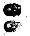
- FIG. 1is a perspective view of a known skull to be used to ascertain a forensic facial approximation for a questioned skull in accordance with an exemplary embodiment of the invention.
- FIG. 2is a perspective view of the known and questioned skulls of FIG. 1 including crest line approximations.
- FIG. 3is a perspective view of the questioned skull of FIG. 1 superimposed on the known skull of FIG. 1 and a known face.
- FIG. 4illustrates three phases of transformation of the known skull into the questioned skull and the resulting third questioned face.
- FIG. 5is a perspective view of the first transformed known skull and the resulting first questioned face of FIG. 4 .
- FIG. 6is a perspective view of the second transformed known skull and the resulting second questioned face of FIG. 4 .
- FIG. 7is a perspective view of the third transformed known skull and the resulting third questioned face of FIG. 4 .
- FIG. 8is a perspective view of the first, second and third transformed known skulls of FIG. 4 shown with alignment points.
- FIG. 9illustrates close up views of a portion of the known skull of FIG. 1 and the first, second and third transformed known skulls of FIG. 4 .
- FIG. 10illustrates a system for performing a forensic facial approximation in accordance with an exemplary embodiment of the invention.
- FIG. 11further illustrates the computational subsystem of FIG. 10 .
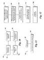
- FIG. 12illustrates process steps for performing a forensic facial approximation in accordance with an exemplary embodiment of the invention.
- FIG. 13illustrates process steps for performing a feature-based reconstruction in accordance with an exemplary embodiment of the invention.
- the present inventiondescribes an apparatus, a system and a method for performing a three-dimensional forensic facial approximation for a skull of unknown identity.
- One exemplary embodiment of the inventionis a system for performing a forensic facial approximation.
- the systemincludes an acquisition subsystem for acquiring models of known skulls and of a questioned skull, and a facial approximation algorithm for comparing the models of the known skulls with the model of the questioned skull and for removing variation in the facial structure of the questioned skull due to skeletal variation between the known skulls and the questioned skull.
- the acquisition subsystemcomprises at least one from the group consisting of a computed tomography machine, an MRI machine, an ultrasound machine, and a laser range finding apparatus, and that the models of the known skulls are superimposed upon the model of the questioned skull and warped to alter the shape of the known skulls to the shape of the questioned skull.
- Another exemplary embodiment of the inventionis a method for performing a forensic facial approximation.
- the methodincludes the steps of acquiring models of known skulls and a model of a questioned skull, comparing the models of the known skulls with the model of the questioned skull, and removing variation in the facial structure of the questioned skull due to skeletal variation between the known skulls and the questioned skull.
- Another exemplary embodiment of the inventionis a method for performing a facial approximation and tailoring the resultant approximation to specific assumed facial characteristics.
- the methodincludes the steps of comparing models of known skulls with a model of a questioned skull, superimposing the models of the known skulls upon the model of the questioned skull, warping the models of the known skulls to alter the shape of the known skulls to the shape of the questioned skull, and removing variation in the facial structure of the questioned skull due to skeletal variation between the known skulls and the questioned skull.
- the removing variation stepincludes superimposing models of known soft tissue upon the questioned skull and warping the models of the known soft tissue to provide the facial structure of the questioned skull.
- the apparatusincludes a bony structure software component for comparing models of known skulls with a model of a questioned skull, a bony structure warping software component for removing variation between the bony structure of the questioned skull and the bony structure of the known skulls, and a soft tissue software component for warping models of soft tissue from the known skulls onto a model of a questioned skull.
- Embodiments of the inventionare directed to a system and a methodology for performing a forensic facial approximation on a questioned skull S Q ( FIG. 1 ).
- the questioned skull S Qis a skull for which an identification is being sought.
- the questioned skull S Qis compared to a multitude of known skulls S K , and characteristics of the known skulls S K are translated onto the questioned skull S Q to provide a mapping from the known skulls S K to the questioned skull S Q .
- the mappingis then applied to the associated known faces F K to derive an average questioned face F Q . Further, characteristics of the known faces F K of the known skulls S K obtained after mapping provide likely variations from the average questioned face F Q .
- FIG. 1illustrates a visual three-dimensional representation of one known skull S K scaled to the size of a visual three-dimensional representation of a questioned skull S Q .
- a database containing representations of known skulls S Kmay include as many as fifty, and possibly as many as one-hundred and fifty or more, separate such representations.
- FIG. 2shows representations of the known skull S K and the questioned skull S Q with crest line approximations 12 superimposed thereon. Crest lines are the tops of ridges in a skull and represent lines about which the skull exhibits a high degree of curvature.
- the representations of the known and questioned skulls S K and S Qare obtained through the use of an acquisition subsystem 52 ( FIG. 10 ).
- the acquisition subsystem 52may include a computed tomography machine, an MRI machine, an ultrasound machine, a laser range finding apparatus, or other similar devices capable of acquiring data useful in facial reconstruction.
- FIGS. 3-9illustrate the generation of a face-space 20 ( FIG. 4 ) that contains a recognizable representation of the questioned face F Q .
- FIGS. 3-9illustrate the generation of a single input to the face-space 20 .
- FIG. 3illustrates the culmination of the preprocessing steps by showing the superimposition of skull S Q on skull S K to form a superimposed skull S S .
- FIG. 3also shows a preprocessed and un-deformed representation of the known face F K .
- representations of the known and questioned skulls S K , S Qare deformed, or warped, through a warping function T (K,Q) ( ).
- This warping functionmaps the known skull S K onto the questioned skull S Q as being approximately equal to T (K,Q) (S K ).
- known skulls S Kare warped onto the questioned skull S Q , and the same warping function is applied to known faces F K , thereby causing warping of the known face F K onto the questioned skull S Q to generate a questioned face F Q .
- These algorithmsare designed to tolerate holes in the representational data (due to missing bony sections) in the questioned skull S Q .
- the warping algorithmis designed to merge the surface of a known skull S K with the surface of a questioned skull S Q , as shown in FIG. 3 .
- a portion of the algorithmsrelies upon finding and matching crest lines 12 or lines of maximal curvature on the skull. Such lines are formally calculated based on spatial derivatives of the skull surface. Approximate crest lines 12 may be determined by looking at the angle of intersection between a pair of triangular patches. If the angle of intersection is high, namely greater than a threshold of thirty degrees (30°), the line of intersection is considered a crest line 12 .
- FIG. 4schematically illustrates the face-space 20 in which the warping, through the warping algorithm, of known skulls S K into the questioned skull S Q forms a questioned face F Q .
- the known skulls S Kare obtained from a known skull database 54 ( FIG. 10 ).
- the known skull database 54is stocked with representations of known skulls S K that are substantially complete, meaning with no missing bony sections.
- the known skull database 54preferably contains between fifty and one hundred and fifty known skulls S K , although in principle the number of known skulls S K is unbounded.
- the individual passes shown in FIG. 4are passes using variants of the same base algorithm. Each pass applies different inputs and parameter settings to bring specific parts of the skulls in alignment in the warping process.
- the first stepprovides rough alignment of skull features based on matching the crest lines 12 of the known skulls S K to those of the questioned skull S Q .
- the second stepis to more tightly align areas of high curvature.
- the third stepis to tightly align smooth areas away from the high curvature areas while maintaining the alignment of the high curvature areas.
- the output of each passbecomes one of the inputs to the next pass.
- the deformations t 1 and t 3move the known skulls S K to the questioned skull S Q .
- the deformation t 2moves the questioned skull S Q onto the known skulls S K , hence, the need for the inverse operator when calculating S K 2 .
- Each of the three passeshas the same construction and includes removing outliers to aid robustness when registering to incomplete skulls. If, for example, an attempt is made to calculate a deformable transformation t i ( ) for pass i, such that S X is approximately t i (S Y ), outlier removal is accomplished by generating a rigid transform r′ i (S X ).
- Such a transformis an iterative closest point (ICP) algorithm that finds points on two skulls that lie close to one another when the skulls are aligned.
- the ICP algorithm(a) selects a set P X of n points from S X , (b) selects a set P Y of the n closest matching points from S Y , (c) calculates the rigid transformation that minimizes the distance between the sets P X and P Y , (d) applies the transform to P X , and (e) starts over by finding a new set P Y .
- the set P Xis denoted as the source landmarks and the set P Y as the target landmarks of r′ i ( ).
- the rigid transformation r′ i ( )rigidly transforms the skulls in a direction opposite from the desired direction. Although this transformation ultimately is discarded, it serves to identify points P Y S Y that are close to S X .
- S Yis a polygonal surface including points, edges and surfaces, and P Y is a subset of the points. It can be reasonably ascertained that at any point p yi P Y has a close corresponding point P xj S X . In other words, if a point is in the target landmarks of the initial rigid transformation, it can be assumed that the point is not an outlier, does not lie over a missing bony structure in the source skull, and must have a close correspondence to a source point.
- a new ICP transform r′ i ( )is then calculated based only on the reduced set of points, such that S X approximates r′ i (P Y ).
- S Xapproximates r′ i (P Y ).
- a final stepis the calculation of a deformation d i .
- This calculationtreats the correspondences as lying in a deformable medium and pushes and pulls points in the source set until they lie close to the target set. Deformations propagate outward from the source points. Alignment between the source points and the corresponding target points is not absolute and a relaxation parameter ⁇ allows the algorithm to trade off positional accuracy of the alignment with stresses induced by the deformation.
- the source landmarks of the second ICP registration, r′ i (P Y ),are selected as the points to be deformed by a thin plate spline.
- the fixed points of the deformationare determined by searching the skull surface S X for the closest point on the skull surface with a surface normal orientation within a threshold of the surface normal at the corresponding point in r′ i (P Y ).
- the three passescalculate successively better approximations for S Q such that S 3 K is a better approximation of S Q than S 2 K , which itself is a better approximation of S Q than S 1 K :
- S 1 Kt 1 ( S K )
- S 2 Kt 2 ⁇ 1 ( S 1 K )
- S 3 Kt 3 ( S 2 K ).
- the passesare conceptually the same, different inputs and different parameters are chosen to achieve desired results.
- the skull featuresare coarsely aligned.
- the selected pointsare limited to points on the crest lines 12 and P X and P Y are limited to roughly two hundred points each.
- the angle constraint between normalsis fairly rigid, requiring source and target points for the deformation T to be within about eighteen degrees.
- the relaxation parameter ⁇is set at 10 to allow the thin plate spline more freedom to define smooth transformations.
- FIG. 5shows a superimposition of the two skulls, denoted as S K1 , following the initial alignment pass.
- FIG. 5further shows the associated facial deformation of the superimposed skull S K1 as F Q1 .
- This first passis designed to bring areas of high curvature on known skulls S K into alignment with corresponding areas on a questioned skull S Q .
- the second passis designed to work similarly to the first pass, except that the matching is from the questioned skull S Q to the known skulls S K .
- the second passattempts to reconcile skull areas where the first pass algorithm was unable to correctly differentiate between multiple candidate crest lines on the questioned skull S Q .
- By running the same algorithm in the opposite direction on the same pointsa higher likelihood is created that conflicts can be resolved.
- the points available for registrationare limited to those lying on crest lines of the skull.
- the number of landmarks used in the registrationis increased to the range of about 200-350.
- FIG. 6illustrates the skull alignment (S K2 ) and corresponding facial deformation (F Q2 ) following the completion of the second pass.
- the major changes from the second passare in the maxilla/front tooth region where the known skull and soft tissue are pulled in toward the questioned skull surface and in the frontal process region where the known skull and soft tissue are pulled out toward the questioned skull surface.
- the third passis intended to complete the skull deformation.
- Stiffer splinesforce greater alignment between the correspondences chosen, and so the relaxation parameter ⁇ is again set at 1 and the deformation T is again set at sixty degrees.
- FIG. 7illustrates the results of the third pass, showing the deformed known skull superimposed on the questioned skull (S K3 ) and showing the corresponding deformed face (F Q3 ).
- Most of the changes from the second passoccur in the flatter regions of the skulls.
- the mandible, frontal bone and anterior portions of the known skullhave been moved into correspondence with the questioned skull.
- the soft tissueshows subtle changes such as a flattening of the crown, and a broader more pronounced cheek region.
- the ICP algorithmis used to align different instances of deformed skulls and used in the selection of landmarks for the thin plate spline deformation.
- the landmarks selected for the three passesare shown in, respectively, FIG. 8 a , FIG. 8 b , and FIG. 8 c .
- the number of landmarks usedincreases from FIG. 8 a (first pass) to FIG. 8 c (third pass).
- all of the landmarks of FIG. 8 b and FIG. 8 care used to calculate the third pass deformation.
- FIG. 9illustrates a close up view of the right zygomatic process and ascending ramus of the mandible of the skulls following each step of the registration.
- FIG. 9 ashows the initial alignment
- FIGS. 9 b - drespectively show the alignments following each of the three passes.
- FIG. 10illustrates a forensic facial approximation system 50 for use in the above-described methodology.
- the illustrated system 50includes an acquisition subsystem 52 , a known skull database 54 , and a computational subsystem 56 .
- the questioned skull S Qis input into the system 50 so that the questioned skull can be compared against the skull representations in the known skull database 54 .
- the warping between the questioned skull S Q and the representations of the known skulls S K from the known skull database 54is accomplished by the computational subsystem 56 .
- the computational subsystem 56includes a computer 58 , or other suitable computing device, and one or more facial approximation algorithms 60.
- the computational subsystem 56may include a bony structure software component for comparing models of known skulls with a model of a questioned skull. Further, the computational subsystem 56 may include a bony structure warping software component for removing variation between the bony structure of the questioned skull and the bony structure of the known skulls and a soft tissue software component for warping models of soft tissue from the known skulls onto a model of a questioned skull.
- Step 100a transformation of the known skulls S K from the known skull database 54 into the questioned skull S Q is performed. The transformation is accomplished through warping of variations.
- Step 100represents the three passes described above with reference to FIGS. 8( a ), 8 ( b ), and 8 ( c ).
- Step 105each three-dimensional skull representation S K 3 is reduced into a one-dimensional vector.
- a matrix of the one-dimensional vectorsis prepared at Step 110 .
- a mean of the matrixis computed to obtain an average face at Step 115 .
- a covarianceis computed.
- the covariancemay be computed through a standard mathematical technique, namely a principle component analysis (PCA).
- PCAutilizes the concept that eigenvectors vary most along the line of the greatest eigenvalue, thus allowing one using PCA to determine how data varies together.
- PCAallows one to denote that the change in one part of the model concurrently causes changes in other parts of the model.
- PCAinstead of independently adjusting each point comprising the representation of the approximated face, one can utilize PCA and ascertain how deformation occurs more naturally through the population of the faces of the known skull database 54 after warping.
- any particular questioned skull S Qmay have additional information that can be used to prevent the change of any particular voxel based upon other voxel changes. For example, one may have heuristic or a priori data regarding the position of the tip of the nose of the questioned skull S Q relative to the face. That data allows certain data in the face space to become static, or to only change a small amount.
- the system and method describedthus far encodes the face and skull as a matrix of radial distance measurements outward from a central axis. Following the generation of the faces F Q , this depth-based encoding forms the basis for the input to the PCA and subsequent generation of the face-space 20 . This is only one of the possible encodings of the faces F Q .
- feature pointssuch as, for example, the tip of the nose or corner of the eye, can be marked and tracked through the warping of the known faces F K into the faces F Q .
- a linearization of the three-dimensional coordinates of these points, augmented by additional points on the face determined from them,can form the basis for the PCA analysis and generation of the face-space 20 , separate from that derived from the depth-based encoding.
- FIG. 13illustrates process steps for feature-based reconstruction.
- Step 200a set of feature points is established for each known face F K .
- Each of these feature pointswill be salient, such as the region around the lips and the eyes, or the tip of the nose.
- Each feature pointcan be designated FP_i, where i indexes into the database.
- Step 205each known face F K is transformed along with its feature points. The transformation is via the known to questioned skull transformation described above.
- Each face F_ibecomes F_i, and each set of transformed points are now defined as fp′_i.
- one arbitrary transformed faceis nominated to be a canonical face F′_c.
- the feature points for the canonical face F′_care fp′_c.
- a warping function wf_i( )is defined such that the feature points fp′_c on the canonical face F′_c are transformed into the feature points for the i'th warped face F′_i at Step 215 .
- the warping function wf_i( )is defined based upon the relationship between the canonical face feature points fp′_c and the i'th warped face feature points fp′_i.
- the warping function wf_i( )is a basic thin plate spline transform. This second warping stage aligns the features of each face F′_I with that of the canonical face F′_c, allowing arbitrary points on the canonical face to be put in to correspondence with points on each of the faces F′_i.
- a new set N of points, f′′p_care selected from the canonical face F′_c.
- f′′p_ccontains those points f′p_c with additional points specified manually to highlight areas of concern, and/or selected randomly by the computer software.
- Correspondences between the points f′′p_c and points on the faces F′_Iare calculated as f′′p_i. This is accomplished by transforming the feature points fp′_c as well as its normal, and then intersecting the normal with the transformed surface.
- the set of points f′′p_Iare linearized by their (x, y, z) coordinates and the resulting vectors composited into a matrix M of the one-dimensional vectors as described with reference to Step 110 .
Landscapes
- Engineering & Computer Science (AREA)
- Theoretical Computer Science (AREA)
- General Physics & Mathematics (AREA)
- Physics & Mathematics (AREA)
- Computer Vision & Pattern Recognition (AREA)
- Medical Informatics (AREA)
- Quality & Reliability (AREA)
- Radiology & Medical Imaging (AREA)
- Nuclear Medicine, Radiotherapy & Molecular Imaging (AREA)
- Health & Medical Sciences (AREA)
- General Health & Medical Sciences (AREA)
- Measuring And Recording Apparatus For Diagnosis (AREA)
- Apparatus For Radiation Diagnosis (AREA)
- Image Processing (AREA)
Abstract
Description

S1K=t1(SK)
S2K=t2−1(S1K), and
S3K=t3(S2K).
Claims (32)
Priority Applications (1)
| Application Number | Priority Date | Filing Date | Title |
|---|---|---|---|
| US10/992,433US7693564B2 (en) | 2004-11-19 | 2004-11-19 | System, apparatus and method for forensic facial approximation |
Applications Claiming Priority (1)
| Application Number | Priority Date | Filing Date | Title |
|---|---|---|---|
| US10/992,433US7693564B2 (en) | 2004-11-19 | 2004-11-19 | System, apparatus and method for forensic facial approximation |
Publications (2)
| Publication Number | Publication Date |
|---|---|
| US20060111631A1 US20060111631A1 (en) | 2006-05-25 |
| US7693564B2true US7693564B2 (en) | 2010-04-06 |
Family
ID=36461835
Family Applications (1)
| Application Number | Title | Priority Date | Filing Date |
|---|---|---|---|
| US10/992,433Expired - Fee RelatedUS7693564B2 (en) | 2004-11-19 | 2004-11-19 | System, apparatus and method for forensic facial approximation |
Country Status (1)
| Country | Link |
|---|---|
| US (1) | US7693564B2 (en) |
Cited By (2)
| Publication number | Priority date | Publication date | Assignee | Title |
|---|---|---|---|---|
| US8135569B2 (en) | 2006-07-19 | 2012-03-13 | Align Technology, Inc. | System and method for three-dimensional complete tooth modeling |
| US20140026102A1 (en)* | 2011-03-31 | 2014-01-23 | Landeskriminalamt Rheinland-Pfalz | Phantom image data bank (3d) |
Families Citing this family (70)
| Publication number | Priority date | Publication date | Assignee | Title |
|---|---|---|---|---|
| US11026768B2 (en) | 1998-10-08 | 2021-06-08 | Align Technology, Inc. | Dental appliance reinforcement |
| US9492245B2 (en) | 2004-02-27 | 2016-11-15 | Align Technology, Inc. | Method and system for providing dynamic orthodontic assessment and treatment profiles |
| US7878805B2 (en) | 2007-05-25 | 2011-02-01 | Align Technology, Inc. | Tabbed dental appliance |
| US8738394B2 (en) | 2007-11-08 | 2014-05-27 | Eric E. Kuo | Clinical data file |
| US8108189B2 (en) | 2008-03-25 | 2012-01-31 | Align Technologies, Inc. | Reconstruction of non-visible part of tooth |
| US8092215B2 (en) | 2008-05-23 | 2012-01-10 | Align Technology, Inc. | Smile designer |
| US9492243B2 (en) | 2008-05-23 | 2016-11-15 | Align Technology, Inc. | Dental implant positioning |
| US8172569B2 (en) | 2008-06-12 | 2012-05-08 | Align Technology, Inc. | Dental appliance |
| US8152518B2 (en) | 2008-10-08 | 2012-04-10 | Align Technology, Inc. | Dental positioning appliance having metallic portion |
| US8292617B2 (en) | 2009-03-19 | 2012-10-23 | Align Technology, Inc. | Dental wire attachment |
| US8765031B2 (en) | 2009-08-13 | 2014-07-01 | Align Technology, Inc. | Method of forming a dental appliance |
| US9241774B2 (en) | 2010-04-30 | 2016-01-26 | Align Technology, Inc. | Patterned dental positioning appliance |
| US9211166B2 (en) | 2010-04-30 | 2015-12-15 | Align Technology, Inc. | Individualized orthodontic treatment index |
| DE102011010975A1 (en)* | 2011-02-10 | 2012-08-16 | Martin Tank | Method and analysis system for geometrical analysis of scan data of oral structures |
| US9403238B2 (en) | 2011-09-21 | 2016-08-02 | Align Technology, Inc. | Laser cutting |
| US9375300B2 (en) | 2012-02-02 | 2016-06-28 | Align Technology, Inc. | Identifying forces on a tooth |
| US9220580B2 (en) | 2012-03-01 | 2015-12-29 | Align Technology, Inc. | Determining a dental treatment difficulty |
| US9414897B2 (en) | 2012-05-22 | 2016-08-16 | Align Technology, Inc. | Adjustment of tooth position in a virtual dental model |
| US9477878B2 (en)* | 2014-01-28 | 2016-10-25 | Disney Enterprises, Inc. | Rigid stabilization of facial expressions |
| US10007988B2 (en) | 2014-02-28 | 2018-06-26 | The Board Of Regents Of The Nevada System Of Higher Education On Behalf Of The University Of Nevada, Las Vegas | Systems and methods for approximating the soft tissue profile of the skull of an unknown subject |
| US10449016B2 (en) | 2014-09-19 | 2019-10-22 | Align Technology, Inc. | Arch adjustment appliance |
| US9610141B2 (en) | 2014-09-19 | 2017-04-04 | Align Technology, Inc. | Arch expanding appliance |
| US9744001B2 (en) | 2014-11-13 | 2017-08-29 | Align Technology, Inc. | Dental appliance with cavity for an unerupted or erupting tooth |
| US10504386B2 (en) | 2015-01-27 | 2019-12-10 | Align Technology, Inc. | Training method and system for oral-cavity-imaging-and-modeling equipment |
| US11554000B2 (en) | 2015-11-12 | 2023-01-17 | Align Technology, Inc. | Dental attachment formation structure |
| US11931222B2 (en) | 2015-11-12 | 2024-03-19 | Align Technology, Inc. | Dental attachment formation structures |
| US11103330B2 (en) | 2015-12-09 | 2021-08-31 | Align Technology, Inc. | Dental attachment placement structure |
| US11596502B2 (en) | 2015-12-09 | 2023-03-07 | Align Technology, Inc. | Dental attachment placement structure |
| US11386556B2 (en) | 2015-12-18 | 2022-07-12 | Orthogrid Systems Holdings, Llc | Deformed grid based intra-operative system and method of use |
| US10201320B2 (en) | 2015-12-18 | 2019-02-12 | OrthoGrid Systems, Inc | Deformed grid based intra-operative system and method of use |
| WO2017218947A1 (en) | 2016-06-17 | 2017-12-21 | Align Technology, Inc. | Intraoral appliances with sensing |
| US10383705B2 (en) | 2016-06-17 | 2019-08-20 | Align Technology, Inc. | Orthodontic appliance performance monitor |
| JP6873832B2 (en)* | 2016-06-30 | 2021-05-19 | オルソグリッド システムズ ソシエテ ア レスポンサビリテ リミテ | Intraoperative system and usage with deformed grid |
| CA3030676A1 (en) | 2016-07-27 | 2018-02-01 | Align Technology, Inc. | Intraoral scanner with dental diagnostics capabilities |
| CN117257492A (en) | 2016-11-04 | 2023-12-22 | 阿莱恩技术有限公司 | Method and apparatus for dental imaging |
| EP3547952B1 (en) | 2016-12-02 | 2020-11-04 | Align Technology, Inc. | Palatal expander |
| WO2018102770A1 (en) | 2016-12-02 | 2018-06-07 | Align Technology, Inc. | Force control, stop mechanism, regulating structure of removable arch adjustment appliance |
| AU2017366755B2 (en) | 2016-12-02 | 2022-07-28 | Align Technology, Inc. | Methods and apparatuses for customizing rapid palatal expanders using digital models |
| US11026831B2 (en) | 2016-12-02 | 2021-06-08 | Align Technology, Inc. | Dental appliance features for speech enhancement |
| US10548700B2 (en) | 2016-12-16 | 2020-02-04 | Align Technology, Inc. | Dental appliance etch template |
| US10779718B2 (en) | 2017-02-13 | 2020-09-22 | Align Technology, Inc. | Cheek retractor and mobile device holder |
| WO2018183358A1 (en) | 2017-03-27 | 2018-10-04 | Align Technology, Inc. | Apparatuses and methods assisting in dental therapies |
| US10613515B2 (en) | 2017-03-31 | 2020-04-07 | Align Technology, Inc. | Orthodontic appliances including at least partially un-erupted teeth and method of forming them |
| US11045283B2 (en) | 2017-06-09 | 2021-06-29 | Align Technology, Inc. | Palatal expander with skeletal anchorage devices |
| CN116942335A (en) | 2017-06-16 | 2023-10-27 | 阿莱恩技术有限公司 | Automatic detection of tooth type and eruption status |
| US10639134B2 (en) | 2017-06-26 | 2020-05-05 | Align Technology, Inc. | Biosensor performance indicator for intraoral appliances |
| US10885521B2 (en) | 2017-07-17 | 2021-01-05 | Align Technology, Inc. | Method and apparatuses for interactive ordering of dental aligners |
| CN111107806B (en) | 2017-07-21 | 2022-04-19 | 阿莱恩技术有限公司 | Jaw profile anchoring |
| CN110996842B (en) | 2017-07-27 | 2022-10-14 | 阿莱恩技术有限公司 | Tooth Staining, Transparency and Glazing |
| EP4278957A3 (en) | 2017-07-27 | 2024-01-24 | Align Technology, Inc. | System and methods for processing an orthodontic aligner by means of an optical coherence tomography |
| US12274597B2 (en)* | 2017-08-11 | 2025-04-15 | Align Technology, Inc. | Dental attachment template tray systems |
| US11116605B2 (en) | 2017-08-15 | 2021-09-14 | Align Technology, Inc. | Buccal corridor assessment and computation |
| US11123156B2 (en) | 2017-08-17 | 2021-09-21 | Align Technology, Inc. | Dental appliance compliance monitoring |
| US12171575B2 (en) | 2017-10-04 | 2024-12-24 | Align Technology, Inc. | Intraoral systems and methods for sampling soft-tissue |
| US10813720B2 (en) | 2017-10-05 | 2020-10-27 | Align Technology, Inc. | Interproximal reduction templates |
| CN111565668B (en) | 2017-10-27 | 2022-06-07 | 阿莱恩技术有限公司 | Substitute occlusion adjusting structure |
| CN111295153B (en) | 2017-10-31 | 2023-06-16 | 阿莱恩技术有限公司 | Dental appliance with selective bite loading and controlled tip staggering |
| CN119235481A (en) | 2017-11-01 | 2025-01-03 | 阿莱恩技术有限公司 | Automatic treatment planning |
| US11534974B2 (en) | 2017-11-17 | 2022-12-27 | Align Technology, Inc. | Customized fabrication of orthodontic retainers based on patient anatomy |
| US11219506B2 (en) | 2017-11-30 | 2022-01-11 | Align Technology, Inc. | Sensors for monitoring oral appliances |
| US11432908B2 (en) | 2017-12-15 | 2022-09-06 | Align Technology, Inc. | Closed loop adaptive orthodontic treatment methods and apparatuses |
| US10614570B2 (en) | 2017-12-20 | 2020-04-07 | International Business Machines Corporation | Medical image exam navigation using simulated anatomical photographs |
| US10521908B2 (en)* | 2017-12-20 | 2019-12-31 | International Business Machines Corporation | User interface for displaying simulated anatomical photographs |
| US10980613B2 (en) | 2017-12-29 | 2021-04-20 | Align Technology, Inc. | Augmented reality enhancements for dental practitioners |
| US10813727B2 (en) | 2018-01-26 | 2020-10-27 | Align Technology, Inc. | Diagnostic intraoral tracking |
| US11937991B2 (en) | 2018-03-27 | 2024-03-26 | Align Technology, Inc. | Dental attachment placement structure |
| EP3773320B1 (en) | 2018-04-11 | 2024-05-15 | Align Technology, Inc. | Releasable palatal expanders |
| WO2020056086A1 (en) | 2018-09-12 | 2020-03-19 | Orthogrid Systems, Inc. | An artificial intelligence intra-operative surgical guidance system and method of use |
| US11540794B2 (en) | 2018-09-12 | 2023-01-03 | Orthogrid Systesm Holdings, LLC | Artificial intelligence intra-operative surgical guidance system and method of use |
| CN112288725B (en)* | 2020-10-30 | 2021-11-02 | 李艳 | Skull center axis perpendicular line determination method and device, storage medium and electronic equipment |
Citations (9)
| Publication number | Priority date | Publication date | Assignee | Title |
|---|---|---|---|---|
| US5214686A (en)* | 1991-12-13 | 1993-05-25 | Wake Forest University | Three-dimensional panoramic dental radiography method and apparatus which avoids the subject's spine |
| US5813984A (en)* | 1997-03-07 | 1998-09-29 | University Radiologists, Inc. | Forensic skull and soft tissue database and on-line facial reconstruction of victims and age progession portrait rendering of missing children through utilization of advance diagnostic radiologic modalities |
| US5844573A (en)* | 1995-06-07 | 1998-12-01 | Massachusetts Institute Of Technology | Image compression by pointwise prototype correspondence using shape and texture information |
| US20030074172A1 (en)* | 2001-02-06 | 2003-04-17 | Michael Ortiz | Method and apparatus for a head injury simulation system |
| US20030226266A1 (en)* | 2002-06-05 | 2003-12-11 | Ellis Stacey L. | Patterning system for a selected body type and methods of measuring for a selected body type |
| US20040236229A1 (en)* | 1999-07-02 | 2004-11-25 | Freeman Jenny E. | Integrated imaging apparatus |
| US20050033142A1 (en)* | 2003-05-09 | 2005-02-10 | University Of Rochester Medical Center | Method of indexing biological imaging data using a three-dimensional body representation |
| US20070038331A1 (en)* | 2003-06-09 | 2007-02-15 | Hanson David F | Human Emulation Robot System |
| US20070052726A1 (en)* | 2005-09-08 | 2007-03-08 | David Wright | Method and system for likeness reconstruction |
- 2004
- 2004-11-19USUS10/992,433patent/US7693564B2/ennot_activeExpired - Fee Related
Patent Citations (9)
| Publication number | Priority date | Publication date | Assignee | Title |
|---|---|---|---|---|
| US5214686A (en)* | 1991-12-13 | 1993-05-25 | Wake Forest University | Three-dimensional panoramic dental radiography method and apparatus which avoids the subject's spine |
| US5844573A (en)* | 1995-06-07 | 1998-12-01 | Massachusetts Institute Of Technology | Image compression by pointwise prototype correspondence using shape and texture information |
| US5813984A (en)* | 1997-03-07 | 1998-09-29 | University Radiologists, Inc. | Forensic skull and soft tissue database and on-line facial reconstruction of victims and age progession portrait rendering of missing children through utilization of advance diagnostic radiologic modalities |
| US20040236229A1 (en)* | 1999-07-02 | 2004-11-25 | Freeman Jenny E. | Integrated imaging apparatus |
| US20030074172A1 (en)* | 2001-02-06 | 2003-04-17 | Michael Ortiz | Method and apparatus for a head injury simulation system |
| US20030226266A1 (en)* | 2002-06-05 | 2003-12-11 | Ellis Stacey L. | Patterning system for a selected body type and methods of measuring for a selected body type |
| US20050033142A1 (en)* | 2003-05-09 | 2005-02-10 | University Of Rochester Medical Center | Method of indexing biological imaging data using a three-dimensional body representation |
| US20070038331A1 (en)* | 2003-06-09 | 2007-02-15 | Hanson David F | Human Emulation Robot System |
| US20070052726A1 (en)* | 2005-09-08 | 2007-03-08 | David Wright | Method and system for likeness reconstruction |
Non-Patent Citations (2)
| Title |
|---|
| "A Survey of Tissue Depth and Landmarks for Facial Approximation"-Kevin W.P. Miller et al. pp. 1-25, Forensic Science Communications, vol. 6. No. 1, Jan. 2004. |
| "A Survey of Tissue Depth and Landmarks for Facial Approximation"—Kevin W.P. Miller et al. pp. 1-25, Forensic Science Communications, vol. 6. No. 1, Jan. 2004. |
Cited By (3)
| Publication number | Priority date | Publication date | Assignee | Title |
|---|---|---|---|---|
| US8135569B2 (en) | 2006-07-19 | 2012-03-13 | Align Technology, Inc. | System and method for three-dimensional complete tooth modeling |
| US20140026102A1 (en)* | 2011-03-31 | 2014-01-23 | Landeskriminalamt Rheinland-Pfalz | Phantom image data bank (3d) |
| US9235320B2 (en)* | 2011-03-31 | 2016-01-12 | Landeskriminalamt Rheinland-Pfalz | Phantom image data bank (3D) |
Also Published As
| Publication number | Publication date |
|---|---|
| US20060111631A1 (en) | 2006-05-25 |
Similar Documents
| Publication | Publication Date | Title |
|---|---|---|
| US7693564B2 (en) | System, apparatus and method for forensic facial approximation | |
| Turner et al. | A novel method of automated skull registration for forensic facial approximation | |
| EP3471657B1 (en) | Method for estimating shape, position and orientation of a dental restoration | |
| Claes et al. | Craniofacial reconstruction using a combined statistical model of face shape and soft tissue depths: methodology and validation | |
| Yamany et al. | Free-form surface registration using surface signatures | |
| Cootes et al. | A unified framework for atlas matching using active appearance models | |
| Quatrehomme et al. | A fully three-dimensional method for facial reconstruction based on deformable models | |
| Yue et al. | Automated 2-D cephalometric analysis on X-ray images by a model-based approach | |
| Jones | Facial Reconstruction Using Volumetric Data. | |
| EP2710557B1 (en) | Fast articulated motion tracking | |
| Duan et al. | Skull identification via correlation measure between skull and face shape | |
| Suetens et al. | Statistically deformable face models for cranio-facial reconstruction | |
| CN110520905A (en) | Face posture apparatus for correcting and method | |
| Vandermeulen et al. | Automated facial reconstruction | |
| Ferková et al. | Age and gender-based human face reconstruction from single frontal image | |
| Tu et al. | Automatic face recognition from skeletal remains | |
| Qian et al. | An automatic tooth reconstruction method based on multimodal data | |
| Tiddeman et al. | Construction and visualisation of three-dimensional facial statistics | |
| De Groeve et al. | Registration of 3D photographs with spiral CT images for soft tissue simulation in maxillofacial surgery | |
| Baumberger et al. | 3d face reconstruction from video using 3d morphable model and silhouette | |
| CN115116586B (en) | Deformable statistical map construction method based on joint registration | |
| Hutton et al. | Automated registration of 3d faces using dense surface models. | |
| JP4814666B2 (en) | Face analysis system | |
| Tu et al. | FACE RECONSTRUCTIONS USING FLESH DEFORMATION | |
| Berar et al. | 3D statistical facial reconstruction |
Legal Events
| Date | Code | Title | Description |
|---|---|---|---|
| AS | Assignment | Owner name:GENERAL ELECTRIC COMPANY, NEW YORK Free format text:ASSIGNMENT OF ASSIGNORS INTEREST;ASSIGNORS:KELLIHER, TIMOTHY PATRICK;TU, PETER HENRY;TURNER, WESLEY DAVID;AND OTHERS;REEL/FRAME:016445/0166;SIGNING DATES FROM 20041209 TO 20050110 Owner name:GENERAL ELECTRIC COMPANY,NEW YORK Free format text:ASSIGNMENT OF ASSIGNORS INTEREST;ASSIGNORS:KELLIHER, TIMOTHY PATRICK;TU, PETER HENRY;TURNER, WESLEY DAVID;AND OTHERS;SIGNING DATES FROM 20041209 TO 20050110;REEL/FRAME:016445/0166 | |
| FEPP | Fee payment procedure | Free format text:PAYOR NUMBER ASSIGNED (ORIGINAL EVENT CODE: ASPN); ENTITY STATUS OF PATENT OWNER: LARGE ENTITY | |
| AS | Assignment | Owner name:GE SECURITY, INC.,FLORIDA Free format text:ASSIGNMENT OF ASSIGNORS INTEREST;ASSIGNOR:GENERAL ELECTRIC COMPANY;REEL/FRAME:023961/0646 Effective date:20100122 Owner name:GE SECURITY, INC., FLORIDA Free format text:ASSIGNMENT OF ASSIGNORS INTEREST;ASSIGNOR:GENERAL ELECTRIC COMPANY;REEL/FRAME:023961/0646 Effective date:20100122 | |
| FPAY | Fee payment | Year of fee payment:4 | |
| FEPP | Fee payment procedure | Free format text:MAINTENANCE FEE REMINDER MAILED (ORIGINAL EVENT CODE: REM.) | |
| LAPS | Lapse for failure to pay maintenance fees | Free format text:PATENT EXPIRED FOR FAILURE TO PAY MAINTENANCE FEES (ORIGINAL EVENT CODE: EXP.) | |
| STCH | Information on status: patent discontinuation | Free format text:PATENT EXPIRED DUE TO NONPAYMENT OF MAINTENANCE FEES UNDER 37 CFR 1.362 | |
| FP | Lapsed due to failure to pay maintenance fee | Effective date:20180406 |