US7691149B2 - Porous titanium modular revision patella system - Google Patents
Porous titanium modular revision patella systemDownload PDFInfo
- Publication number
- US7691149B2 US7691149B2US11/434,464US43446406AUS7691149B2US 7691149 B2US7691149 B2US 7691149B2US 43446406 AUS43446406 AUS 43446406AUS 7691149 B2US7691149 B2US 7691149B2
- Authority
- US
- United States
- Prior art keywords
- stem
- annular
- recess
- patellar implant
- anterior
- Prior art date
- Legal status (The legal status is an assumption and is not a legal conclusion. Google has not performed a legal analysis and makes no representation as to the accuracy of the status listed.)
- Expired - Fee Related, expires
Links
- 210000004417patellaAnatomy0.000titledescription82
- RTAQQCXQSZGOHL-UHFFFAOYSA-NTitaniumChemical compound[Ti]RTAQQCXQSZGOHL-UHFFFAOYSA-N0.000titledescription4
- 239000010936titaniumSubstances0.000titledescription4
- 229910052719titaniumInorganic materials0.000titledescription4
- 239000007943implantSubstances0.000claimsabstractdescription50
- 238000000926separation methodMethods0.000claimsabstractdescription5
- 229910052751metalInorganic materials0.000claimsdescription26
- 239000002184metalSubstances0.000claimsdescription26
- 239000004698PolyethyleneSubstances0.000claimsdescription22
- -1polyethylenePolymers0.000claimsdescription22
- 229920000573polyethylenePolymers0.000claimsdescription22
- 230000000295complement effectEffects0.000claimsdescription11
- 230000000717retained effectEffects0.000claimsdescription4
- 230000013011matingEffects0.000claimsdescription2
- 210000000988bone and boneAnatomy0.000description13
- 210000001519tissueAnatomy0.000description11
- 238000000034methodMethods0.000description10
- 210000000426patellar ligamentAnatomy0.000description10
- 238000002513implantationMethods0.000description8
- 238000001356surgical procedureMethods0.000description7
- 210000003127kneeAnatomy0.000description6
- 239000002639bone cementSubstances0.000description4
- 210000000629knee jointAnatomy0.000description3
- 210000000689upper legAnatomy0.000description3
- 239000011248coating agentSubstances0.000description2
- 238000000576coating methodMethods0.000description2
- 230000003068static effectEffects0.000description2
- CYJRNFFLTBEQSQ-UHFFFAOYSA-N8-(3-methyl-1-benzothiophen-5-yl)-N-(4-methylsulfonylpyridin-3-yl)quinoxalin-6-amineChemical compoundCS(=O)(=O)C1=C(C=NC=C1)NC=1C=C2N=CC=NC2=C(C=1)C=1C=CC2=C(C(=CS2)C)C=1CYJRNFFLTBEQSQ-UHFFFAOYSA-N0.000description1
- OKTJSMMVPCPJKN-UHFFFAOYSA-NCarbonChemical compound[C]OKTJSMMVPCPJKN-UHFFFAOYSA-N0.000description1
- WAIPAZQMEIHHTJ-UHFFFAOYSA-N[Cr].[Co]Chemical class[Cr].[Co]WAIPAZQMEIHHTJ-UHFFFAOYSA-N0.000description1
- 239000000853adhesiveSubstances0.000description1
- 230000001070adhesive effectEffects0.000description1
- 239000000919ceramicSubstances0.000description1
- 229910002804graphiteInorganic materials0.000description1
- 239000010439graphiteSubstances0.000description1
- 239000000463materialSubstances0.000description1
- 238000012986modificationMethods0.000description1
- 230000004048modificationEffects0.000description1
- 239000011148porous materialSubstances0.000description1
- 210000004872soft tissueAnatomy0.000description1
- 239000007787solidSubstances0.000description1
- 239000000758substrateSubstances0.000description1
- 230000000153supplemental effectEffects0.000description1
- 210000002435tendonAnatomy0.000description1
- 230000007704transitionEffects0.000description1
Images


Classifications
- A—HUMAN NECESSITIES
- A61—MEDICAL OR VETERINARY SCIENCE; HYGIENE
- A61F—FILTERS IMPLANTABLE INTO BLOOD VESSELS; PROSTHESES; DEVICES PROVIDING PATENCY TO, OR PREVENTING COLLAPSING OF, TUBULAR STRUCTURES OF THE BODY, e.g. STENTS; ORTHOPAEDIC, NURSING OR CONTRACEPTIVE DEVICES; FOMENTATION; TREATMENT OR PROTECTION OF EYES OR EARS; BANDAGES, DRESSINGS OR ABSORBENT PADS; FIRST-AID KITS
- A61F2/00—Filters implantable into blood vessels; Prostheses, i.e. artificial substitutes or replacements for parts of the body; Appliances for connecting them with the body; Devices providing patency to, or preventing collapsing of, tubular structures of the body, e.g. stents
- A61F2/02—Prostheses implantable into the body
- A61F2/30—Joints
- A61F2/38—Joints for elbows or knees
- A61F2/3877—Patellae or trochleae
- A—HUMAN NECESSITIES
- A61—MEDICAL OR VETERINARY SCIENCE; HYGIENE
- A61F—FILTERS IMPLANTABLE INTO BLOOD VESSELS; PROSTHESES; DEVICES PROVIDING PATENCY TO, OR PREVENTING COLLAPSING OF, TUBULAR STRUCTURES OF THE BODY, e.g. STENTS; ORTHOPAEDIC, NURSING OR CONTRACEPTIVE DEVICES; FOMENTATION; TREATMENT OR PROTECTION OF EYES OR EARS; BANDAGES, DRESSINGS OR ABSORBENT PADS; FIRST-AID KITS
- A61F2/00—Filters implantable into blood vessels; Prostheses, i.e. artificial substitutes or replacements for parts of the body; Appliances for connecting them with the body; Devices providing patency to, or preventing collapsing of, tubular structures of the body, e.g. stents
- A61F2/02—Prostheses implantable into the body
- A61F2/30—Joints
- A61F2002/30001—Additional features of subject-matter classified in A61F2/28, A61F2/30 and subgroups thereof
- A61F2002/30316—The prosthesis having different structural features at different locations within the same prosthesis; Connections between prosthetic parts; Special structural features of bone or joint prostheses not otherwise provided for
- A61F2002/30535—Special structural features of bone or joint prostheses not otherwise provided for
- A61F2002/30604—Special structural features of bone or joint prostheses not otherwise provided for modular
- A61F2002/30614—Sets comprising both primary and revision endoprostheses
- A—HUMAN NECESSITIES
- A61—MEDICAL OR VETERINARY SCIENCE; HYGIENE
- A61F—FILTERS IMPLANTABLE INTO BLOOD VESSELS; PROSTHESES; DEVICES PROVIDING PATENCY TO, OR PREVENTING COLLAPSING OF, TUBULAR STRUCTURES OF THE BODY, e.g. STENTS; ORTHOPAEDIC, NURSING OR CONTRACEPTIVE DEVICES; FOMENTATION; TREATMENT OR PROTECTION OF EYES OR EARS; BANDAGES, DRESSINGS OR ABSORBENT PADS; FIRST-AID KITS
- A61F2/00—Filters implantable into blood vessels; Prostheses, i.e. artificial substitutes or replacements for parts of the body; Appliances for connecting them with the body; Devices providing patency to, or preventing collapsing of, tubular structures of the body, e.g. stents
- A61F2/02—Prostheses implantable into the body
- A61F2/30—Joints
- A61F2/30767—Special external or bone-contacting surface, e.g. coating for improving bone ingrowth
- A61F2/30771—Special external or bone-contacting surface, e.g. coating for improving bone ingrowth applied in original prostheses, e.g. holes or grooves
- A61F2002/30878—Special external or bone-contacting surface, e.g. coating for improving bone ingrowth applied in original prostheses, e.g. holes or grooves with non-sharp protrusions, for instance contacting the bone for anchoring, e.g. keels, pegs, pins, posts, shanks, stems, struts
- A—HUMAN NECESSITIES
- A61—MEDICAL OR VETERINARY SCIENCE; HYGIENE
- A61F—FILTERS IMPLANTABLE INTO BLOOD VESSELS; PROSTHESES; DEVICES PROVIDING PATENCY TO, OR PREVENTING COLLAPSING OF, TUBULAR STRUCTURES OF THE BODY, e.g. STENTS; ORTHOPAEDIC, NURSING OR CONTRACEPTIVE DEVICES; FOMENTATION; TREATMENT OR PROTECTION OF EYES OR EARS; BANDAGES, DRESSINGS OR ABSORBENT PADS; FIRST-AID KITS
- A61F2/00—Filters implantable into blood vessels; Prostheses, i.e. artificial substitutes or replacements for parts of the body; Appliances for connecting them with the body; Devices providing patency to, or preventing collapsing of, tubular structures of the body, e.g. stents
- A61F2/02—Prostheses implantable into the body
- A61F2/30—Joints
- A61F2/30767—Special external or bone-contacting surface, e.g. coating for improving bone ingrowth
- A61F2/30907—Nets or sleeves applied to surface of prostheses or in cement
- A61F2002/30909—Nets
- A—HUMAN NECESSITIES
- A61—MEDICAL OR VETERINARY SCIENCE; HYGIENE
- A61F—FILTERS IMPLANTABLE INTO BLOOD VESSELS; PROSTHESES; DEVICES PROVIDING PATENCY TO, OR PREVENTING COLLAPSING OF, TUBULAR STRUCTURES OF THE BODY, e.g. STENTS; ORTHOPAEDIC, NURSING OR CONTRACEPTIVE DEVICES; FOMENTATION; TREATMENT OR PROTECTION OF EYES OR EARS; BANDAGES, DRESSINGS OR ABSORBENT PADS; FIRST-AID KITS
- A61F2/00—Filters implantable into blood vessels; Prostheses, i.e. artificial substitutes or replacements for parts of the body; Appliances for connecting them with the body; Devices providing patency to, or preventing collapsing of, tubular structures of the body, e.g. stents
- A61F2/02—Prostheses implantable into the body
- A61F2/30—Joints
- A61F2/30767—Special external or bone-contacting surface, e.g. coating for improving bone ingrowth
- A61F2002/3092—Special external or bone-contacting surface, e.g. coating for improving bone ingrowth having an open-celled or open-pored structure
- A—HUMAN NECESSITIES
- A61—MEDICAL OR VETERINARY SCIENCE; HYGIENE
- A61F—FILTERS IMPLANTABLE INTO BLOOD VESSELS; PROSTHESES; DEVICES PROVIDING PATENCY TO, OR PREVENTING COLLAPSING OF, TUBULAR STRUCTURES OF THE BODY, e.g. STENTS; ORTHOPAEDIC, NURSING OR CONTRACEPTIVE DEVICES; FOMENTATION; TREATMENT OR PROTECTION OF EYES OR EARS; BANDAGES, DRESSINGS OR ABSORBENT PADS; FIRST-AID KITS
- A61F2310/00—Prostheses classified in A61F2/28 or A61F2/30 - A61F2/44 being constructed from or coated with a particular material
- A61F2310/00005—The prosthesis being constructed from a particular material
- A61F2310/00011—Metals or alloys
- A61F2310/00023—Titanium or titanium-based alloys, e.g. Ti-Ni alloys
Definitions
- This inventionrelates generally to a method and apparatus for use in patella revision surgery, and more particularly, to a method and apparatus for implanting a modular patellar implant having a polyethylene portion and a porous metal portion.
- the patellais generally a flat, triangular bone located on the front of the knee joint. It is supported in the tendon of the quadriceps. The patella serves to protect the front of the knee and increase the leverage of the quadriceps.
- a patellar implantmay be formed entirely of polyethylene.
- it may be difficult to stabilize such an implant relative to the surrounding tissuebecause a polyethylene surface may not be conducive to bone or soft tissue ingrowth. Consequently, securement of an entirely polyethylene patellar implant to a host patella may rely entirely on external fasteners such as sutures.
- a patellar implantmay comprise a polyethylene component having a porous metal backing secured by bone cement.
- bone cementmay present drawbacks. Application of bone cement may require careful placement and accuracy when locating the adhesive. Such a requirement may increase having excess bone cement entering the surrounding tissue and increase the surgery time.
- a patellar implantincludes a posterior portion and an anterior portion.
- the posterior portionmay define an articulating surface and a first retaining feature.
- the anterior portionmay define a tissue engaging portion and a second retaining feature adapted to advance into a mechanical interlock with the first retaining feature in an assembled position.
- the mechanical interlock between the first and second retaining featuresmay cooperate to resist separation of the posterior and anterior portions in the assembled position.
- the first retaining featurecan include a stem defining a proximal end extending from a body.
- the stemcan include an intermediate portion and a distal end.
- a radius of the stemcan increase from the intermediate portion to the distal end.
- the second retaining featurecan be defined by a recess formed in the anterior portion.
- the recesscan be formed from an inboard surface of the anterior portion through an intermediate area to a terminal end. A radius defined by the recess can increase from the intermediate area to the terminal end.
- first retaining featurecan be integrally formed with the posterior portion and the second retaining feature can be integrally formed with the anterior portion.
- the first and second retaining featurescan cooperate to form a press-fit relationship when advanced to the assembled position.
- the second retaining featurefurther includes a snap-ring retained within a first annular pocket formed on the recess of the anterior portion.
- the snap ringcan nest within a second annular pocket formed on the stem of the posterior portion in the assembled position.
- the posterior portioncan define a first anti-rotation element thereon.
- the anterior portioncan define a second anti-rotation element thereon.
- the first and second anti-rotation elementscan be adapted to cooperatively mate and resist rotation of the posterior portion relative to the anterior portion in the assembled position.
- the first and second anti-rotation featurescan define a protrusion formed on one of the posterior portion and the anterior portion and a depression formed on the other of the posterior portion and the anterior portion.
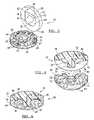
- FIG. 1is an exploded perspective view of a modular patella system including a polyethylene component and a porous metal component according to the present teachings;
- FIG. 2is another exploded perspective view of the modular patella system of FIG. 1 illustrating an inboard face of the polyethylene component;
- FIG. 3is an exploded perspective view of the modular patella system of FIG. 1 shown with the polyethylene component tilted for illustration;
- FIG. 4is a sectional view of the modular patella system taken along line 4 - 4 of FIG. 2 ;
- FIG. 5is an assembled perspective view of the modular patella system of FIG. 1 ;
- FIG. 6is a sectional view of the modular patella system taken along line 6 - 6 of FIG. 5 ;
- FIG. 7is an exploded perspective view of a modular patella system including a polyethylene component and a porous metal component according to additional features of the present teachings;
- FIG. 8is another exploded perspective view of the modular patella system of FIG. 7 illustrating an inboard face of the porous metal component
- FIG. 9is an exploded perspective view of the modular patella system of FIG. 7 shown with the polyethylene component tilted for illustration;
- FIG. 10is a sectional view of the modular patella system taken along line 10 - 10 of FIG. 7 ;
- FIG. 11is an assembled perspective view of the modular patella system of FIG. 7 ;
- FIG. 12is a sectional view of the modular patella system taken along line 12 - 12 of FIG. 11 ;
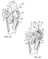
- FIG. 13illustrates an exemplary right knee having a host patella rotated laterally to gain access to a posterior patella face for implantation of an exemplary anterior portion according to a first example
- FIG. 14illustrates an exemplary posterior portion being assembled onto the anterior portion according to the present teachings
- FIG. 15illustrates the anterior and posterior portions in an assembled position implanted onto the posterior patella
- FIG. 16illustrates the host patella and assembled implant of FIG. 15 rotated medially into an implanted position
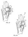
- FIG. 17illustrates an exemplary right knee having a host patella rotated laterally to gain access to a posterior patella face for implantation of pre-assembled anterior and posterior portion according to a second example
- FIG. 18illustrates a pre-assembled implant prior to implantation onto the posterior patella
- FIG. 19illustrates the pre-assembled implant of FIG. 18 secured to the posterior patella
- FIG. 20illustrates the host patella and assembled implant of FIG. 19 rotated medially into an implanted position
- FIG. 21illustrates an exemplary right knee having an unsuitable host patella being removed for implantation of a patellar implant according to additional features
- FIG. 22illustrates an exemplary anterior portion secured to the patellar tendon for receipt of an exemplary posterior portion
- FIG. 23illustrates the posterior portion assembled onto the anterior portion into an assembled position
- FIG. 24illustrates the assembled implant rotated medially into an implanted position
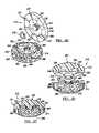
- FIG. 25is an exploded perspective view of a modular patella system including a polyethylene component and a porous metal component according to additional features of the present teachings;
- FIG. 26is a sectional view of the modular patella system of FIG. 25 ;
- FIG. 27is a sectional view of the modular patella system of FIG. 26 shown in an assembled position.
- the modular patella system 10generally includes a posterior portion 12 and an anterior portion 14 .
- the posterior portion 12may be formed of polyethylene.
- the anterior portion 14may be formed of porous metal such as titanium for example.
- the modular patella system 10may be used for patella revision surgery where minimal existing bone is present, or where no useful existing patella remains.
- the modular patella systemmay be adapted to be attached to the posterior surface of the shallow existing patella bone.
- the patellamay be removed entirely and the modular patella system attached to surrounding tissue such as to the patellar tendon.
- the posterior portion 12generally includes a body 18 having a radial sidewall 20 .
- a convex surface 22( FIG. 1 ) may be defined on an anterior face 24 .
- An inboard face 26defines a central radial pocket 28 .
- a first integrally formed retaining member 30may extend from the inboard face 26 of the posterior portion 12 .
- the first integrally formed retaining member 30may include a stem 32 .
- the stem 32may generally define a proximal end 34 extending from the inboard face 26 of the body 18 , an intermediate portion 36 and a distal end 38 . As illustrated most clearly in FIG. 6 , a radius of the stem 32 may generally increase from the intermediate portion 36 toward the distal end 38 and toward the proximal end 34 .
- a pair of anti-rotation elements 40may be defined on the inboard face 26 of the posterior portion 12 .
- the anti-rotation elements 40may define depressions 42 ( FIG. 3 ) formed in the inboard face 26 of the posterior portion 12 .
- the depressions 42may define radial inset members formed in the central radial pocket 28 .
- the depressions 42may extend from the inboard face 26 into the body 18 at a depth substantially equivalent to the central radial pocket 28 .
- a collection of passages 48may be formed substantially through the body 18 of the posterior portion 12 . More specifically, passages 48 may extend from the convex outer surface 22 toward the inboard face 26 of the posterior portion 12 . In the example shown, the passages 48 do not extend entirely through the body 18 . However, the passages 48 may alternatively pass entirely through the body 18 .
- a bridge 50FIG. 1 ) may be defined between adjacent pairs of passages 48 . As will become appreciated, the bridge 50 may provide an engagement surface when securing the modular patella system 10 to an implant site with sutures.
- the anterior portion 14generally includes a body 54 having a radial sidewall 56 .
- a convex surface 60( FIG. 2 ) may be defined on an anterior face 62 .
- An inboard face 64may define a central hub 66 .
- a second integrally formed retaining member 70may be defined on the anterior portion 14 .
- the second integrally formed retaining member 70may be defined by a recess 72 formed in the anterior portion 14 .
- the recess 72may be defined from the inboard face 64 at the hub 72 through an intermediate area 74 to a terminal end 76 .
- a radius defined by the recess 72may increase from the intermediate area 74 to the terminal end 76 and to the inboard face 64 .
- the first and second integrally formed retaining members 30 and 70may define complementary shapes suitable to provide a press-fit relationship in an assembled position ( FIG. 6 ).
- the anterior portion 14further defines a pair of complementary anti-rotation elements 80 in the form of protrusions 82 extending from the inboard face 64 of the anterior portion 14 .
- the protrusions 82may nest within the depressions 42 formed in the posterior portion 12 to inhibit relative rotation of the posterior and anterior portions 12 and 14 , respectively.
- the anterior portion 14may define a series of passages 84 formed in locations to align with the collection of passages 48 in the posterior portion 12 .
- the passages 48 and 84respectively, may be utilized to pass suture during attachment to surrounding bone and/or tissue.
- alternate passages 84 ′may define a recesses 87 extending to the outer radial surface of the anterior portion 14 for protecting suture during use.
- the stem 32 of the posterior portion 12may be located proximate the recess 72 of the anterior portion 14 ( FIG. 4 ). It may be necessary to at least partially align the respective anti-rotation features 40 and 80 .
- the stem 32may be advanced in a direction defined by its longitudinal axis (in a direction downwardly as viewed in FIG. 4 ).
- a radius defined at the distal portion 38 of the stem 32may be larger than a radius defined at the intermediate area 74 of the recess 72 .
- the distal portion 38 of the stem 32may contract slightly while passing through the intermediate area 74 of the recess 72 .
- the distal end 38 of the stem 32may be advanced to the terminal end 76 of the recess 72 ( FIG. 6 ).
- the distal end 38 of the stem 32may expand to its normal position defined by a radius larger than a radius defined by the intermediate area 74 of the recess 72 .
- the stem 32may be retained by the recess 72 in a secure assembled position such that separation of the posterior and anterior portions 12 and 14 is inhibited.
- the posterior and anterior portions 12 and 14collectively define a patellar implant 85 generally having a biconvex structure.
- the central hub 66 and protrusions 82 of the anterior portion 14may define a lateral sidewall 86 .
- the central radial pocket 28 of the posterior portion 12may define a tapered sidewall 88 .
- the respective surfaces 86 and 88may provide supplemental retaining capacity in the assembled position.
- the porous material of the posterior portion 12may slightly expand at the tapered sidewall 88 until the anterior portion 14 is provided adequate clearance during assembly of the posterior portion 12 and the anterior portion 14 .
- the lateral sidewall 86may also be tapered.
- a modular patella system according to a second exampleis shown and identified generally at reference numeral 110 .
- the second exampleincludes a posterior portion 112 and an anterior portion 114 .
- the posterior portion 112may be formed of polyethylene.
- the anterior portion 114may be formed of porous metal such as titanium for example. Exemplary methods for making porous metal may be found in co-pending applications, (U.S. Ser. No. 11/357,929, filed Feb. 17, 2006), entitled “Method and Apparatus for Forming Porous Metal Implants”, (U.S. Ser. No. 11/111,123 filed, Apr. 21, 2005; Ser. No. 11/294,692, filed Dec.
- the modular patella system 110may be used for patella revision surgery where minimal existing bone is present, or where no useful existing patella remains.
- the posterior portion 112may define a body 118 having a convex posterior face 122 and an inboard face 126 .
- the inboard face 126may include a first integrally formed retaining member 130 .
- the first integrally formed retaining member 130may include a stem 132 .
- the stem 132may generally define a proximal end 134 extending from the inboard face 126 of the body 118 , an intermediate portion 136 and a distal end 138 .
- a transition between the intermediate portion 136 and the distal end 138may be defined by a tapered annular surface 139 .
- the intermediate portion 136may define a first annular pocket 140 .
- Two pair of anti-rotation elements 141may be defined on the inboard face 126 of the posterior portion 112 .
- the anti-rotation elements 141define depressions 142 in the form of rectangular cavities. It is appreciated that other geometries may be defined by the depressions 142 .
- the anterior portion 114may generally include a body 154 having a convex anterior face 160 and an inboard face 164 .
- a second integrally formed retaining member 170may be defined on the anterior portion 114 .
- the second integrally formed retaining member 170may be defined by a recess 172 formed in the anterior portion 114 .
- the recess 172may be defined from the inboard face 164 through an intermediate area 174 to a terminal end 176 .
- the intermediate area 174may define a second annular pocket 177 .
- the second annular pocket 177may support a snap-ring 178 therein.
- the anterior portion 114may define two pair of complementary anti-rotation elements 180 in the form of rectangular protrusions 182 extending from the inboard face 164 of the anterior portion 114 . In an assembled position 182 , the protrusions may nest within the depressions 142 formed in the posterior portion 112 to inhibit relative rotation of the posterior and anterior portions 112 and 114 , respectively.
- the anterior portion 114may further define a series of passages 184 formed through the body 154 . As will be described in detail later, the respective passages 184 may be utilized to pass suture or screws during attachment to surrounding bone and/or tissue.
- the stem 132 of the posterior portion 112may be located proximate the recess 172 of the anterior portion 114 . It may be necessary to at least partially align the respective anti-rotation features 141 and 180 .
- the stem 132may be advanced in a direction defined by its longitudinal axis (in a direction downwardly as viewed in FIG. 10 ). As the stem 132 is inserted into the recess 172 , the annular tapered surface 139 may slidably negotiate through the snap-ring 178 thereby urging the snap-ring 178 outwardly to accept the outer diameter of the distal portion 138 .
- the snap-ring 178may contract to a static position ( FIG. 12 ). In the static position, the snap-ring 178 may generally nest within an area defined by the first and second annular pockets 140 and 177 . In the assembled position, the snap-ring 178 may resist axial movement of the stem 132 and therefore securely retain the posterior and anterior portions 112 and 114 , respectively, together.
- the assembled posterior and anterior portions 112 and 114 , respectively,are hereinafter referred to collectively as implant 185 .
- FIGS. 13-16a first exemplary method of implanting the modular patella system 10 of FIGS. 1-6 will be described.
- the anterior portionhas been shown without the porous metal detail. It is appreciated, however, that each anterior portion may be comprised entirely of porous metal such as depicted in FIGS. 1-12 .
- the modular patella system 10may be used for patella revision surgery where minimal existing bone is present.
- an existing patella 200is shown within a patellar tendon 202 of a right knee 204 .
- the exemplary patella 200is generally shallow and suitable for attachment by the modular patella system 10 .
- the patella 200may be rotated about a superior/inferior axis to gain access to a posterior surface 206 of the existing patella 200 .
- the patella 200is rotated laterally. To allow such rotation, it may be necessary to make an incision 210 in the patellar tendon 202 .
- the posterior patella 206may be reamed to define a smooth concave posterior surface 212 complementary to the convex surface 60 of the anterior portion 14 .
- the anterior portion 14may be secured against the posterior surface 212 of the patella 200 .
- Sutures 218may be passed through any or all of the passages 84 provided in the anterior portion 14 to facilitate attachment.
- the sutures 218may pass through holes formed in the patella 200 and/or surrounding tissue including the patellar tendon 202 . While some of the passages are depicted as 84 and others 84 ′, it is appreciated that the passages may comprise all passages 84 , all passages 84 ′ or any combination thereof. Other methods of attachment are contemplated, such as but not limited to, fasteners such as bone screws. In one example, the attachment structure, such as bone screws may be formed of resorbable material.
- the stem 32 of the posterior portion 12may be inserted into the recess 72 of the anterior portion 14 into an assembled position as described above.
- the implant 85may then be rotated back to the original orientation of the patella 200 ( FIG. 16 ).
- the incision 210 in the patellar tendonmay then be closed such as by sutures 220 .
- a lateral portion 226 of the convex outer surface 22 of the posterior (polyethylene) portion 12may be adapted for articulation with a lateral condyle of the femur (not shown).
- a medial portion 228 of the convex outer surface 22 of the posterior portion 12may be adapted for articulation with a medial condyle of the femur (not shown).
- the posterior and anterior portions 12 and 14may be assembled together prior to implantation at the implant site.
- the implant 85may be secured to the existing patella 200 by way of sutures 218 passed through the passages on the posterior portion 12 and complementary passages on the anterior portion 14 .
- the respective bridge portions 50may provide a bearing surface for the sutures 218 in an attached position. It is appreciated in one example, some or all of the passages 48 may need to be pierced completely through the body 18 as needed.
- the anterior portion 114may be implanted at the implant site precedent to assembly with the posterior portion 112 .
- the existing patella 230 of a knee joint 232was not suitable for implant attachment and therefore, has been removed.
- the anterior portion 114may be secured such as by sutures 218 through some or all of the passages 184 to the surrounding tissue such as the patellar tendon 202 .
- the stem 132may be subsequently inserted into the recess 172 until the snap-ring 178 (not specifically shown) captures the posterior and anterior portions together as described in greater detail above.
- the implant 185may be placed in the desired location relative to the surrounding bone and tissue ( FIG. 24 ). Again, while this particular example has been shown implanted at an implant site wherein a patella has been removed, the same principles may be applied to implanting the modular patella system 110 to a shallow existing patella using similar steps outlined above with respect to the modular patella system.
- the porous metal located anteriorly on the implantmay encourage bone and tissue ingrowth, such as with an existing patella and/or patellar tendon.
- the polyethylene located proximally on the implantmay provide a smooth articulation surface to complement the respective condyles of the femur.
- a setcomprised of various diameters and thicknesses of cooperating posterior and anterior portions may be provided.
- a surgeonmay select one posterior portion from a collection of posterior portions suitable for the particular patient.
- a surgeonmay select one anterior portion from a collection of anterior portions according to the particular needs of the patient.
- the complementary mating featuresi.e., the integrally formed retaining features and anti-rotation features may be equivalent to support such interchangeability.
- the third exampleincludes a posterior portion 312 and an anterior portion 314 .
- the anterior portion 314may be formed of porous metal such as titanium for example.
- the modular patella system 310may be used for patella revision surgery where minimal existing bone is present, or where no useful existing patella remains.
- the posterior portion 312may define a body 318 having a convex posterior face 322 and an inboard face 326 .
- the convex posterior face 322can be uniformly convex.
- the inboard face 326may include a first integrally formed retaining member 330 .
- the first integrally formed retaining member 330may include a stem 332 .
- the stem 332is generally configured similar to the stem 132 ( FIGS. 8-12 ).
- the body 318can also include an annular radial pocket 333 that surrounds the stem 332 .
- the annular radial pocket 333can be formed by a continuous tapered surface 335 .
- Anti-rotation elements 341may be defined on the inboard face 326 of the posterior portion 312 .
- the anti-rotation elements 141define a collection of depressions and extensions 342 and 343 , respectively.
- the anterior portion 314may generally include a body 354 having a convex anterior face 360 and an inboard face 364 .
- the body 354can include an annular central hub 366 having a continuous tapered surface 368 .
- the convex anterior face 360can be uniformly convex.
- a second integrally formed retaining member 370may be defined on the anterior portion 314 .
- the second integrally formed retaining member 370may be defined by a recess 372 formed in the anterior portion 314 .
- the recess 372may be defined from the inboard face 364 through an intermediate area 374 to a terminal end 376 .
- the intermediate area 374may define a second annular pocket 377 .
- the second annular pocket 377may support a snap ring 378 therein.
- the anterior portion 314may define a series of complementary anti-rotation elements 380 .
- the anti-rotation elements 380define a collection of depressions and extensions 382 and 383 , respectively.
- the depressions and extensions 342 and 343 of the posterior portion 312are adapted to cooperatively mate with the depressions and extensions 382 and 383 of the anterior portion 314 in an assembled position ( FIG. 27 ).
- Steps for assembling the posterior and anterior portions 312 and 314are substantially similar to those described with respect to the modular patella system 110 .
- a method of implanting the modular patella system 310is substantially similar to the method described in relation to the modular patella system 110 .
- the integrally formed retaining featuresmay also provide anti-rotation characteristics.
- the anti-rotation featuresmay be formed with the integrally formed retaining features instead of separately.
- the stem and recessmay define shapes other than cylindrical. Some exemplary shapes may include oval, rectangular, triangular, octagonal and others. In such an example, the respective surfaces defined by the stem and recess may discourage rotation of the stem within the recess providing an anti-rotation feature between the proximal and anterior portions.
- the broad teachings of the present inventioncan be implemented in a variety of forms.
- the posterior portionhas been described as having the stem and the anterior portion has been described as defining the recess, one skilled in the art will appreciate that the respective features may be swapped.
- the respective integrally formed retaining featuresmay define other structures suitable for interconnection.
- a threaded male portionmay be defined on one of the posterior and anterior portions and a grooved female portion may be defined on the other portion.
- Other configurationsare contemplated.
- the respective anterior portionshave been described as porous metal, they may alternatively comprise solid metal having a porous coating.
- the articulation surfacemay alternatively comprise ceramic, a ceramic-like isotropic coating over a graphite substrate, cobalt-chromium compounds.
Landscapes
- Health & Medical Sciences (AREA)
- Orthopedic Medicine & Surgery (AREA)
- Physical Education & Sports Medicine (AREA)
- Cardiology (AREA)
- Oral & Maxillofacial Surgery (AREA)
- Transplantation (AREA)
- Engineering & Computer Science (AREA)
- Biomedical Technology (AREA)
- Heart & Thoracic Surgery (AREA)
- Vascular Medicine (AREA)
- Life Sciences & Earth Sciences (AREA)
- Animal Behavior & Ethology (AREA)
- General Health & Medical Sciences (AREA)
- Public Health (AREA)
- Veterinary Medicine (AREA)
- Prostheses (AREA)
Abstract
Description
Claims (23)
Priority Applications (2)
| Application Number | Priority Date | Filing Date | Title |
|---|---|---|---|
| US11/434,464US7691149B2 (en) | 2006-05-15 | 2006-05-15 | Porous titanium modular revision patella system |
| US12/697,851US8268005B2 (en) | 2006-05-15 | 2010-02-01 | Porous titanium modular revision patella system |
Applications Claiming Priority (1)
| Application Number | Priority Date | Filing Date | Title |
|---|---|---|---|
| US11/434,464US7691149B2 (en) | 2006-05-15 | 2006-05-15 | Porous titanium modular revision patella system |
Related Child Applications (1)
| Application Number | Title | Priority Date | Filing Date |
|---|---|---|---|
| US12/697,851DivisionUS8268005B2 (en) | 2006-05-15 | 2010-02-01 | Porous titanium modular revision patella system |
Publications (2)
| Publication Number | Publication Date |
|---|---|
| US20070265708A1 US20070265708A1 (en) | 2007-11-15 |
| US7691149B2true US7691149B2 (en) | 2010-04-06 |
Family
ID=38686133
Family Applications (2)
| Application Number | Title | Priority Date | Filing Date |
|---|---|---|---|
| US11/434,464Expired - Fee RelatedUS7691149B2 (en) | 2006-05-15 | 2006-05-15 | Porous titanium modular revision patella system |
| US12/697,851Active2027-01-15US8268005B2 (en) | 2006-05-15 | 2010-02-01 | Porous titanium modular revision patella system |
Family Applications After (1)
| Application Number | Title | Priority Date | Filing Date |
|---|---|---|---|
| US12/697,851Active2027-01-15US8268005B2 (en) | 2006-05-15 | 2010-02-01 | Porous titanium modular revision patella system |
Country Status (1)
| Country | Link |
|---|---|
| US (2) | US7691149B2 (en) |
Cited By (3)
| Publication number | Priority date | Publication date | Assignee | Title |
|---|---|---|---|---|
| US20080300689A1 (en)* | 2006-01-23 | 2008-12-04 | Mc Kinnon Brian W | Patellar Components |
| US8535386B2 (en) | 2010-10-21 | 2013-09-17 | Howmedica Osteonics Corp. | Stem with pressfit porous element |
| US10893948B2 (en) | 2017-11-02 | 2021-01-19 | Howmedica Osteonics Corp. | Rotary arc patella articulating geometry |
Families Citing this family (20)
| Publication number | Priority date | Publication date | Assignee | Title |
|---|---|---|---|---|
| US7691149B2 (en)* | 2006-05-15 | 2010-04-06 | Biomet Manufacturing Corp. | Porous titanium modular revision patella system |
| US20100131069A1 (en)* | 2007-08-01 | 2010-05-27 | Jeffrey Halbrecht | Method and system for patella tendon realignment |
| US20100198354A1 (en)* | 2007-08-01 | 2010-08-05 | Jeffrey Halbrecht | Method and system for patella tendon realignment |
| US8696754B2 (en)* | 2008-09-03 | 2014-04-15 | Biomet Manufacturing, Llc | Revision patella prosthesis |
| CA2771332C (en) | 2009-08-27 | 2020-11-10 | Cotera, Inc. | Method and apparatus for force redistribution in articular joints |
| US10349980B2 (en) | 2009-08-27 | 2019-07-16 | The Foundry, Llc | Method and apparatus for altering biomechanics of the shoulder |
| US9861408B2 (en) | 2009-08-27 | 2018-01-09 | The Foundry, Llc | Method and apparatus for treating canine cruciate ligament disease |
| US9668868B2 (en) | 2009-08-27 | 2017-06-06 | Cotera, Inc. | Apparatus and methods for treatment of patellofemoral conditions |
| US9278004B2 (en) | 2009-08-27 | 2016-03-08 | Cotera, Inc. | Method and apparatus for altering biomechanics of the articular joints |
| WO2012021812A2 (en)* | 2010-08-13 | 2012-02-16 | Smith & Nephew, Inc. | Patellar implants |
| US9125749B2 (en)* | 2010-10-22 | 2015-09-08 | Farid Amirouche | Patellar implant with variable weights for knee repair surgery |
| US9498342B2 (en) | 2010-12-30 | 2016-11-22 | Depuy Ireland Unlimited Company | Knee prosthesis having commonly-sized patella components with varying thicknesses and peak surface diameters |
| US9675399B2 (en) | 2011-02-14 | 2017-06-13 | Michael D. Ries | Patient specific implants and instrumentation for patellar prostheses |
| EP2675399B1 (en) | 2011-02-14 | 2016-02-03 | Ries, Michael D. | Patellar prostheses |
| US9468466B1 (en) | 2012-08-24 | 2016-10-18 | Cotera, Inc. | Method and apparatus for altering biomechanics of the spine |
| WO2014159919A1 (en)* | 2013-03-14 | 2014-10-02 | Zimmer Knee Creations, Inc. | Methods and devices for patellar resurfacing treatment |
| US11896476B2 (en) | 2020-01-02 | 2024-02-13 | Zkr Orthopedics, Inc. | Patella tendon realignment implant with changeable shape |
| WO2021142686A1 (en)* | 2020-01-13 | 2021-07-22 | 丽水市人民医院 | Knee extension bridging apparatus for use in post-patellofemoral replacement revision |
| WO2021231253A1 (en) | 2020-05-11 | 2021-11-18 | Zkr Orthopedics, Inc. | Adjustable patellar tendon realignment implant |
| EP4056153B1 (en)* | 2021-03-10 | 2025-07-09 | Globus Medical, Inc. | Systems for knee arthroplasty |
Citations (49)
| Publication number | Priority date | Publication date | Assignee | Title |
|---|---|---|---|---|
| US3927423A (en) | 1974-06-07 | 1975-12-23 | Alfred B Swanson | Patellar implant and method |
| US3964106A (en) | 1975-03-03 | 1976-06-22 | Physical Systems, Inc. | Three-part total knee prosthesis |
| US4041550A (en)* | 1976-07-30 | 1977-08-16 | Frazier Calvin H | Artificial patella and method of repairing a natural patella |
| US4158894A (en) | 1978-03-13 | 1979-06-26 | Worrell Richard V | Patellar prosthesis and method of implanting the same |
| US4759768A (en)* | 1987-02-11 | 1988-07-26 | Thierry Hermann | Joint prosthesis, in particular finger joint prosthesis |
| EP0307654A2 (en) | 1987-09-15 | 1989-03-22 | S + G Implants Gmbh | Implant as a substitute for a surgically removed patella part |
| US4913157A (en) | 1986-06-03 | 1990-04-03 | Analog Devices, Inc. | Ultrasound method and apparatus for evaluating, in vivo, bone conditions |
| FR2642301A1 (en) | 1989-01-31 | 1990-08-03 | Laboureau Jacques Philippe | Composite prosthesis, intended in particular for replacement of the patella, the tibial plates, the cotyles or any other articulation, and providing a shock-absorbing effect |
| US5011496A (en)* | 1988-02-02 | 1991-04-30 | Joint Medical Products Corporation | Prosthetic joint |
| US5019104A (en)* | 1990-01-16 | 1991-05-28 | Dow Corning Wright Corporation | Patellar prosthesis and method of making the same |
| US5181924A (en) | 1991-07-05 | 1993-01-26 | Sulzer Medizinaltechnik Ag | Patella prosthesis |
| US5197986A (en) | 1990-04-11 | 1993-03-30 | Mikhail Michael W E | Recessed patellar prosthesis |
| US5236462A (en) | 1991-04-23 | 1993-08-17 | Mikhail Michael W E | Metal-backed patellar prosthesis |
| US5236461A (en) | 1991-03-22 | 1993-08-17 | Forte Mark R | Totally posterior stabilized knee prosthesis |
| US5358529A (en) | 1993-03-05 | 1994-10-25 | Smith & Nephew Richards Inc. | Plastic knee femoral implants |
| US5405395A (en) | 1993-05-03 | 1995-04-11 | Wright Medical Technology, Inc. | Modular femoral implant |
| US5425775A (en) | 1992-06-23 | 1995-06-20 | N.K. Biotechnical Engineering Company | Method for measuring patellofemoral forces |
| US5480443A (en) | 1992-01-31 | 1996-01-02 | Elias; Sarmed G. | Artifical implant component and method for securing same |
| US5522901A (en)* | 1992-06-26 | 1996-06-04 | Eska Implants Gmbh | Implant for replacing a rear patella part |
| US5571196A (en) | 1994-10-24 | 1996-11-05 | Stein; Daniel | Patello-femoral joint replacement device and method |
| US5609640A (en) | 1991-07-05 | 1997-03-11 | Johnson; David P. | Patella prostheses |
| US5609644A (en) | 1994-03-23 | 1997-03-11 | Howmedica International | Prosthetic patello femoral joint assembly |
| US5658348A (en)* | 1996-09-09 | 1997-08-19 | Bristol-Myers Squibb Company | Acetabular implant with threaded liner and locking ring |
| US5702467A (en) | 1996-06-12 | 1997-12-30 | Johnson & Johnson Professional, Inc. | Patellar resurfacing component |
| US5725591A (en)* | 1996-08-13 | 1998-03-10 | Johnson & Johnson Professional, Inc. | Acetabular bearing system |
| US5876455A (en) | 1997-07-24 | 1999-03-02 | Harwin; Steven F. | Bio-shim |
| US5885298A (en) | 1994-02-23 | 1999-03-23 | Biomet, Inc. | Patellar clamp and reamer with adjustable stop |
| US6146423A (en)* | 1999-01-28 | 2000-11-14 | Implex Corporation | Patella replacement apparatus |
| US6416553B1 (en) | 1999-03-31 | 2002-07-09 | Biomet, Inc. | Method and apparatus for providing a modular acetabular prosthesis |
| US20020128719A1 (en)* | 2001-03-06 | 2002-09-12 | Burkinshaw Brian D. | Mobile bearing patella prosthesis |
| US20030088315A1 (en)* | 2001-11-08 | 2003-05-08 | Supinski Robert S | Patella replacement apparatus |
| US6616696B1 (en) | 1998-09-04 | 2003-09-09 | Alan C. Merchant | Modular knee replacement system |
| US6620198B2 (en)* | 1999-10-07 | 2003-09-16 | Exactech, Inc. | Composite bearing inserts for total knee joints |
| US6702821B2 (en) | 2000-01-14 | 2004-03-09 | The Bonutti 2003 Trust A | Instrumentation for minimally invasive joint replacement and methods for using same |
| US20040064192A1 (en)* | 2002-09-27 | 2004-04-01 | Bubb Stephen K. | Porous implant system and treatment method |
| US20040143337A1 (en)* | 2003-01-21 | 2004-07-22 | Brian Burkinshaw | Mobile bearing patellar prosthesis with orbital translation |
| US20040143336A1 (en)* | 2003-01-22 | 2004-07-22 | Brian Burkinshaw | Two-piece modular patellar prosthetic system |
| US6770078B2 (en) | 2000-01-14 | 2004-08-03 | Peter M. Bonutti | Movable knee implant and methods therefor |
| US6855150B1 (en) | 2001-07-13 | 2005-02-15 | Timothy R. Linehan | Patellar trial and drill guide for use in knee replacement surgery |
| US20060100714A1 (en)* | 2003-04-02 | 2006-05-11 | Ortho Development Corporation | Tibial augment connector |
| US7048741B2 (en) | 2002-05-10 | 2006-05-23 | Swanson Todd V | Method and apparatus for minimally invasive knee arthroplasty |
| US20060241776A1 (en) | 2005-04-21 | 2006-10-26 | Biomet Manufacturing Corp. | Method and apparatus for use of porous implants |
| US20060241781A1 (en) | 2005-04-21 | 2006-10-26 | Biomet Manufacturing Corp. | Method and apparatus for use of porous implants |
| US20070129809A1 (en) | 2005-12-05 | 2007-06-07 | Biomet Manufacturing Corp. | Apparatus for use of porous implants |
| US20070173948A1 (en) | 2005-04-21 | 2007-07-26 | Biomet Manufacturing Corp. | Porous metal cup with cobalt bearing surface |
| US20070196230A1 (en) | 2006-02-17 | 2007-08-23 | Biomet Manufacturing Corp. | Method and apparatus for forming porous metal implants |
| US20070250175A1 (en) | 2001-02-23 | 2007-10-25 | Biomet Manufacturing Corp. | Method And Appartus For Acetabular Reconstruction |
| US20080147187A1 (en) | 2005-04-21 | 2008-06-19 | Biomet Manufacturing Corp. | Method And Apparatus For Use Of Porous Implants |
| US20090084491A1 (en) | 2007-09-25 | 2009-04-02 | Biomet Manufacturing Corp. | Cementless Tibial Tray |
Family Cites Families (16)
| Publication number | Priority date | Publication date | Assignee | Title |
|---|---|---|---|---|
| GB9420071D0 (en)* | 1994-10-05 | 1994-11-16 | Howmedica | Metal backing for inclusion in the manufacture of a prosthetic component |
| US5702465A (en)* | 1996-05-13 | 1997-12-30 | Sulzer Orthopedics Inc. | Patella prosthesis having rotational and translational freedom |
| US6010534A (en)* | 1997-09-25 | 2000-01-04 | Johnson & Johnson Professional, Inc. | Rotatable tibial prosthesis with keyed axial securement |
| US6053945A (en)* | 1997-09-25 | 2000-04-25 | Johnson & Johnson Professional, Inc. | Joint prosthesis having controlled rotation |
| US5951603A (en)* | 1997-09-25 | 1999-09-14 | Johnson & Johnson Professional, Inc. | Rotatable joint prosthesis with axial securement |
| US5957979A (en)* | 1997-12-12 | 1999-09-28 | Bristol-Myers Squibb Company | Mobile bearing knee with metal on metal interface |
| US6572655B1 (en) | 1998-08-26 | 2003-06-03 | Lanny L. Johnson | Method for securing a prosthesis component to bone |
| AU771796B2 (en)* | 1999-02-03 | 2004-04-01 | Depuy Orthopaedics, Inc. | Modular joint prosthesis system |
| US6923831B2 (en)* | 1999-05-10 | 2005-08-02 | Barry M. Fell | Surgically implantable knee prosthesis having attachment apertures |
| US20050033424A1 (en)* | 1999-05-10 | 2005-02-10 | Fell Barry M. | Surgically implantable knee prosthesis |
| US20030125745A1 (en) | 2001-11-05 | 2003-07-03 | Bio One Tech Inc. | Bone-fixing device |
| US20040143338A1 (en)* | 2003-01-21 | 2004-07-22 | Brian Burkinshaw | Multi-piece modular patellar prosthetic system |
| US7846183B2 (en) | 2004-02-06 | 2010-12-07 | Spinal Elements, Inc. | Vertebral facet joint prosthesis and method of fixation |
| US20070135924A1 (en)* | 2005-12-14 | 2007-06-14 | Verhoogen Alex R | Joint replacement prosthesis, joint replacement mounting stud and method |
| US7691149B2 (en) | 2006-05-15 | 2010-04-06 | Biomet Manufacturing Corp. | Porous titanium modular revision patella system |
| US8696754B2 (en) | 2008-09-03 | 2014-04-15 | Biomet Manufacturing, Llc | Revision patella prosthesis |
- 2006
- 2006-05-15USUS11/434,464patent/US7691149B2/ennot_activeExpired - Fee Related
- 2010
- 2010-02-01USUS12/697,851patent/US8268005B2/enactiveActive
Patent Citations (52)
| Publication number | Priority date | Publication date | Assignee | Title |
|---|---|---|---|---|
| US3927423A (en) | 1974-06-07 | 1975-12-23 | Alfred B Swanson | Patellar implant and method |
| US3964106A (en) | 1975-03-03 | 1976-06-22 | Physical Systems, Inc. | Three-part total knee prosthesis |
| US4041550A (en)* | 1976-07-30 | 1977-08-16 | Frazier Calvin H | Artificial patella and method of repairing a natural patella |
| US4158894A (en) | 1978-03-13 | 1979-06-26 | Worrell Richard V | Patellar prosthesis and method of implanting the same |
| US4913157A (en) | 1986-06-03 | 1990-04-03 | Analog Devices, Inc. | Ultrasound method and apparatus for evaluating, in vivo, bone conditions |
| US4759768A (en)* | 1987-02-11 | 1988-07-26 | Thierry Hermann | Joint prosthesis, in particular finger joint prosthesis |
| EP0307654A2 (en) | 1987-09-15 | 1989-03-22 | S + G Implants Gmbh | Implant as a substitute for a surgically removed patella part |
| US5011496A (en)* | 1988-02-02 | 1991-04-30 | Joint Medical Products Corporation | Prosthetic joint |
| FR2642301A1 (en) | 1989-01-31 | 1990-08-03 | Laboureau Jacques Philippe | Composite prosthesis, intended in particular for replacement of the patella, the tibial plates, the cotyles or any other articulation, and providing a shock-absorbing effect |
| US5019104A (en)* | 1990-01-16 | 1991-05-28 | Dow Corning Wright Corporation | Patellar prosthesis and method of making the same |
| US5383937A (en) | 1990-04-11 | 1995-01-24 | Mikhail; W. E. Michael | Recessed patellar prosthesis |
| US5197986A (en) | 1990-04-11 | 1993-03-30 | Mikhail Michael W E | Recessed patellar prosthesis |
| US5236461A (en) | 1991-03-22 | 1993-08-17 | Forte Mark R | Totally posterior stabilized knee prosthesis |
| US5236462A (en) | 1991-04-23 | 1993-08-17 | Mikhail Michael W E | Metal-backed patellar prosthesis |
| US5181924A (en) | 1991-07-05 | 1993-01-26 | Sulzer Medizinaltechnik Ag | Patella prosthesis |
| US5609640A (en) | 1991-07-05 | 1997-03-11 | Johnson; David P. | Patella prostheses |
| US5480443A (en) | 1992-01-31 | 1996-01-02 | Elias; Sarmed G. | Artifical implant component and method for securing same |
| US5425775A (en) | 1992-06-23 | 1995-06-20 | N.K. Biotechnical Engineering Company | Method for measuring patellofemoral forces |
| US5522901A (en)* | 1992-06-26 | 1996-06-04 | Eska Implants Gmbh | Implant for replacing a rear patella part |
| US5358529A (en) | 1993-03-05 | 1994-10-25 | Smith & Nephew Richards Inc. | Plastic knee femoral implants |
| US5405395A (en) | 1993-05-03 | 1995-04-11 | Wright Medical Technology, Inc. | Modular femoral implant |
| US5885298A (en) | 1994-02-23 | 1999-03-23 | Biomet, Inc. | Patellar clamp and reamer with adjustable stop |
| US5609644A (en) | 1994-03-23 | 1997-03-11 | Howmedica International | Prosthetic patello femoral joint assembly |
| US5571196A (en) | 1994-10-24 | 1996-11-05 | Stein; Daniel | Patello-femoral joint replacement device and method |
| US5702467A (en) | 1996-06-12 | 1997-12-30 | Johnson & Johnson Professional, Inc. | Patellar resurfacing component |
| US5725591A (en)* | 1996-08-13 | 1998-03-10 | Johnson & Johnson Professional, Inc. | Acetabular bearing system |
| US5658348A (en)* | 1996-09-09 | 1997-08-19 | Bristol-Myers Squibb Company | Acetabular implant with threaded liner and locking ring |
| US5876455A (en) | 1997-07-24 | 1999-03-02 | Harwin; Steven F. | Bio-shim |
| US6616696B1 (en) | 1998-09-04 | 2003-09-09 | Alan C. Merchant | Modular knee replacement system |
| US6146423A (en)* | 1999-01-28 | 2000-11-14 | Implex Corporation | Patella replacement apparatus |
| US6416553B1 (en) | 1999-03-31 | 2002-07-09 | Biomet, Inc. | Method and apparatus for providing a modular acetabular prosthesis |
| US6620198B2 (en)* | 1999-10-07 | 2003-09-16 | Exactech, Inc. | Composite bearing inserts for total knee joints |
| US6702821B2 (en) | 2000-01-14 | 2004-03-09 | The Bonutti 2003 Trust A | Instrumentation for minimally invasive joint replacement and methods for using same |
| US6770078B2 (en) | 2000-01-14 | 2004-08-03 | Peter M. Bonutti | Movable knee implant and methods therefor |
| US20070250175A1 (en) | 2001-02-23 | 2007-10-25 | Biomet Manufacturing Corp. | Method And Appartus For Acetabular Reconstruction |
| US6602292B2 (en) | 2001-03-06 | 2003-08-05 | Centerpulse Orthopedic Inc. | Mobile bearing patella prosthesis |
| US20020128719A1 (en)* | 2001-03-06 | 2002-09-12 | Burkinshaw Brian D. | Mobile bearing patella prosthesis |
| US6855150B1 (en) | 2001-07-13 | 2005-02-15 | Timothy R. Linehan | Patellar trial and drill guide for use in knee replacement surgery |
| US20030088315A1 (en)* | 2001-11-08 | 2003-05-08 | Supinski Robert S | Patella replacement apparatus |
| US7048741B2 (en) | 2002-05-10 | 2006-05-23 | Swanson Todd V | Method and apparatus for minimally invasive knee arthroplasty |
| US20040064192A1 (en)* | 2002-09-27 | 2004-04-01 | Bubb Stephen K. | Porous implant system and treatment method |
| US20040143337A1 (en)* | 2003-01-21 | 2004-07-22 | Brian Burkinshaw | Mobile bearing patellar prosthesis with orbital translation |
| US6800094B2 (en)* | 2003-01-21 | 2004-10-05 | Zimmer Technology, Inc. | Mobile bearing patellar prosthesis with orbital translation |
| US20040143336A1 (en)* | 2003-01-22 | 2004-07-22 | Brian Burkinshaw | Two-piece modular patellar prosthetic system |
| US20060100714A1 (en)* | 2003-04-02 | 2006-05-11 | Ortho Development Corporation | Tibial augment connector |
| US20060241776A1 (en) | 2005-04-21 | 2006-10-26 | Biomet Manufacturing Corp. | Method and apparatus for use of porous implants |
| US20060241781A1 (en) | 2005-04-21 | 2006-10-26 | Biomet Manufacturing Corp. | Method and apparatus for use of porous implants |
| US20070173948A1 (en) | 2005-04-21 | 2007-07-26 | Biomet Manufacturing Corp. | Porous metal cup with cobalt bearing surface |
| US20080147187A1 (en) | 2005-04-21 | 2008-06-19 | Biomet Manufacturing Corp. | Method And Apparatus For Use Of Porous Implants |
| US20070129809A1 (en) | 2005-12-05 | 2007-06-07 | Biomet Manufacturing Corp. | Apparatus for use of porous implants |
| US20070196230A1 (en) | 2006-02-17 | 2007-08-23 | Biomet Manufacturing Corp. | Method and apparatus for forming porous metal implants |
| US20090084491A1 (en) | 2007-09-25 | 2009-04-02 | Biomet Manufacturing Corp. | Cementless Tibial Tray |
Non-Patent Citations (4)
| Title |
|---|
| Augmentation Patella, Zimmer, http://www.zimmer.com/ctl?template=MP&action=&id=698&op=global&pr=Y (printed Mar. 8, 2006). |
| European Search Report mailed Nov. 20, 2009 for EP09169382 claiming benefit of U.S. Appl. No. 12/203575, filed Sep. 3, 2008. |
| NexGen All Poly Patella, Zimmer, Inc., Mar. 8, 2006 (1 page). |
| NexGen Complete Knee Solution System-"Primary Porous Patella with Trabecular Metal" copyright 2001 Zimmer, Inc., (2 sheets). |
Cited By (5)
| Publication number | Priority date | Publication date | Assignee | Title |
|---|---|---|---|---|
| US20080300689A1 (en)* | 2006-01-23 | 2008-12-04 | Mc Kinnon Brian W | Patellar Components |
| US8142509B2 (en) | 2006-01-23 | 2012-03-27 | Smith & Nephew, Inc. | Patellar components |
| US8535386B2 (en) | 2010-10-21 | 2013-09-17 | Howmedica Osteonics Corp. | Stem with pressfit porous element |
| US8926708B2 (en) | 2010-10-21 | 2015-01-06 | Howmedica Osteonics Corp. | Stem with pressfit porous element |
| US10893948B2 (en) | 2017-11-02 | 2021-01-19 | Howmedica Osteonics Corp. | Rotary arc patella articulating geometry |
Also Published As
| Publication number | Publication date |
|---|---|
| US20070265708A1 (en) | 2007-11-15 |
| US8268005B2 (en) | 2012-09-18 |
| US20100131068A1 (en) | 2010-05-27 |
Similar Documents
| Publication | Publication Date | Title |
|---|---|---|
| US7691149B2 (en) | Porous titanium modular revision patella system | |
| AU2022211895B2 (en) | Tibial tray with fixation features | |
| US11648127B2 (en) | Method and system including sleeves and broaches for surgically preparing the patient's bone | |
| US9408704B2 (en) | Revision knee tibial locking mechanism | |
| US9398956B2 (en) | Fixed-bearing knee prosthesis having interchangeable components | |
| US8128703B2 (en) | Fixed-bearing knee prosthesis having interchangeable components | |
| US8105386B2 (en) | Rotating/non-rotating tibia base plate/insert system | |
| US8771364B2 (en) | Tibial tray having a reinforcing member | |
| EP2046248B1 (en) | Apparatus for a knee implant | |
| US8808375B2 (en) | Anti-backout arthroscopic uni-compartmental prosthesis | |
| EP2777624B1 (en) | Orthopaedic prosthesis | |
| JP2004121850A (en) | Inverted type humerus prosthesis | |
| US7998218B1 (en) | Modular orthopedic implant | |
| US9138322B2 (en) | Knee prosthesis having cross-compatible dome and anatomic patella components | |
| EP4188283B1 (en) | Tibial implant with improved anterior load transfer | |
| JP7163088B2 (en) | Systems and methods for orthopedic joint replacement procedures | |
| AU2014201526B2 (en) | Mechanical assembly of titanium foam pegs |
Legal Events
| Date | Code | Title | Description |
|---|---|---|---|
| AS | Assignment | Owner name:BIOMET MANUFACTURING CORP., INDIANA Free format text:ASSIGNMENT OF ASSIGNORS INTEREST;ASSIGNORS:BROWN, DAVID R.;BOLLINGER, MARK A.;MAY, BRIAN M.;AND OTHERS;REEL/FRAME:017904/0046 Effective date:20060511 Owner name:BIOMET MANUFACTURING CORP.,INDIANA Free format text:ASSIGNMENT OF ASSIGNORS INTEREST;ASSIGNORS:BROWN, DAVID R.;BOLLINGER, MARK A.;MAY, BRIAN M.;AND OTHERS;REEL/FRAME:017904/0046 Effective date:20060511 | |
| AS | Assignment | Owner name:BANK OF AMERICA, N.A., AS ADMINISTRATIVE AGENT FOR Free format text:SECURITY AGREEMENT;ASSIGNORS:LVB ACQUISITION, INC.;BIOMET, INC.;REEL/FRAME:020362/0001 Effective date:20070925 | |
| STCF | Information on status: patent grant | Free format text:PATENTED CASE | |
| CC | Certificate of correction | ||
| AS | Assignment | Owner name:BIOMET MANUFACTURING, LLC, INDIANA Free format text:CHANGE OF NAME;ASSIGNOR:BIOMET MANUFACTURING CORPORATION;REEL/FRAME:030656/0702 Effective date:20130603 | |
| FPAY | Fee payment | Year of fee payment:4 | |
| AS | Assignment | Owner name:LVB ACQUISITION, INC., INDIANA Free format text:RELEASE OF SECURITY INTEREST IN PATENTS RECORDED AT REEL 020362/ FRAME 0001;ASSIGNOR:BANK OF AMERICA, N.A., AS ADMINISTRATIVE AGENT;REEL/FRAME:037155/0133 Effective date:20150624 Owner name:BIOMET, INC., INDIANA Free format text:RELEASE OF SECURITY INTEREST IN PATENTS RECORDED AT REEL 020362/ FRAME 0001;ASSIGNOR:BANK OF AMERICA, N.A., AS ADMINISTRATIVE AGENT;REEL/FRAME:037155/0133 Effective date:20150624 | |
| MAFP | Maintenance fee payment | Free format text:PAYMENT OF MAINTENANCE FEE, 8TH YEAR, LARGE ENTITY (ORIGINAL EVENT CODE: M1552) Year of fee payment:8 | |
| FEPP | Fee payment procedure | Free format text:MAINTENANCE FEE REMINDER MAILED (ORIGINAL EVENT CODE: REM.); ENTITY STATUS OF PATENT OWNER: LARGE ENTITY | |
| LAPS | Lapse for failure to pay maintenance fees | Free format text:PATENT EXPIRED FOR FAILURE TO PAY MAINTENANCE FEES (ORIGINAL EVENT CODE: EXP.); ENTITY STATUS OF PATENT OWNER: LARGE ENTITY | |
| STCH | Information on status: patent discontinuation | Free format text:PATENT EXPIRED DUE TO NONPAYMENT OF MAINTENANCE FEES UNDER 37 CFR 1.362 | |
| FP | Lapsed due to failure to pay maintenance fee | Effective date:20220406 |