US7691042B2 - Abdominal exercising apparatus and method - Google Patents
Abdominal exercising apparatus and methodDownload PDFInfo
- Publication number
- US7691042B2 US7691042B2US12/386,488US38648807AUS7691042B2US 7691042 B2US7691042 B2US 7691042B2US 38648807 AUS38648807 AUS 38648807AUS 7691042 B2US7691042 B2US 7691042B2
- Authority
- US
- United States
- Prior art keywords
- bench
- frame
- support
- lumbar support
- extension
- Prior art date
- Legal status (The legal status is an assumption and is not a legal conclusion. Google has not performed a legal analysis and makes no representation as to the accuracy of the status listed.)
- Expired - Fee Related, expires
Links
Images


Classifications
- A—HUMAN NECESSITIES
- A63—SPORTS; GAMES; AMUSEMENTS
- A63B—APPARATUS FOR PHYSICAL TRAINING, GYMNASTICS, SWIMMING, CLIMBING, OR FENCING; BALL GAMES; TRAINING EQUIPMENT
- A63B23/00—Exercising apparatus specially adapted for particular parts of the body
- A63B23/02—Exercising apparatus specially adapted for particular parts of the body for the abdomen, the spinal column or the torso muscles related to shoulders (e.g. chest muscles)
- A63B23/0205—Abdomen
- A63B23/0216—Abdomen moving lower limbs with immobilized torso
- A—HUMAN NECESSITIES
- A63—SPORTS; GAMES; AMUSEMENTS
- A63B—APPARATUS FOR PHYSICAL TRAINING, GYMNASTICS, SWIMMING, CLIMBING, OR FENCING; BALL GAMES; TRAINING EQUIPMENT
- A63B21/00—Exercising apparatus for developing or strengthening the muscles or joints of the body by working against a counterforce, with or without measuring devices
- A63B21/40—Interfaces with the user related to strength training; Details thereof
- A63B21/4027—Specific exercise interfaces
- A63B21/4029—Benches specifically adapted for exercising
- A—HUMAN NECESSITIES
- A63—SPORTS; GAMES; AMUSEMENTS
- A63B—APPARATUS FOR PHYSICAL TRAINING, GYMNASTICS, SWIMMING, CLIMBING, OR FENCING; BALL GAMES; TRAINING EQUIPMENT
- A63B23/00—Exercising apparatus specially adapted for particular parts of the body
- A63B23/02—Exercising apparatus specially adapted for particular parts of the body for the abdomen, the spinal column or the torso muscles related to shoulders (e.g. chest muscles)
- A63B23/0205—Abdomen
- A63B23/0211—Abdomen moving torso with immobilized lower limbs
- A—HUMAN NECESSITIES
- A63—SPORTS; GAMES; AMUSEMENTS
- A63B—APPARATUS FOR PHYSICAL TRAINING, GYMNASTICS, SWIMMING, CLIMBING, OR FENCING; BALL GAMES; TRAINING EQUIPMENT
- A63B21/00—Exercising apparatus for developing or strengthening the muscles or joints of the body by working against a counterforce, with or without measuring devices
- A63B21/06—User-manipulated weights
- A63B21/062—User-manipulated weights including guide for vertical or non-vertical weights or array of weights to move against gravity forces
- A63B21/0626—User-manipulated weights including guide for vertical or non-vertical weights or array of weights to move against gravity forces with substantially vertical guiding means
- A63B21/0628—User-manipulated weights including guide for vertical or non-vertical weights or array of weights to move against gravity forces with substantially vertical guiding means for vertical array of weights
Definitions
- the present inventionrelates to an abdominal exercise apparatus.
- the inventionrelates to a bench with an adjustable support that fully extends the lumbar section of the vertebral column and safeguards the normal curvature of the spine during a sit-up or legs-up movement.
- Exercises aimed at strengthening the abdominal musclesinclude the traditional sit-up and legs-up movements. This type of movement, typically performed lying supine on a flat surface of the floor causes negative stress to the spine and can lead to back muscle and spinal injuries. Because of the flat surface, the starting position tilts the pelvis and tends to straighten the natural curvature of the lumbar section of the spine. When performing a sit-up or legs-up movement in this position, injuries such as back muscle strain, particularly the lumbar muscles, or abnormal compression of intervertebral discs leading to slipped or herniated discs and pinched nerves may occur.
- the ordinary sit-up movementis initiated in the neck area, specifically by the contraction of the neck muscles, followed by the pectoral muscles and finally the abdominal muscles. This progression of muscle groups produces negative stress along the length of the spine tending to straighten it first in the cervical section, then in the thoracic section, and finally in the lumbar section. Because the lumbar section of the spine is unsupported by the flat floor, the ordinary legs-up movement produces the same compressive pressures on the vertebral column as the sit-up movement.
- FIG. 9illustrates the negative stresses on the spine and the tendency to straighten the spine during an ordinary sit-up movement performed on a flat surface.
- the first 15° of the movementare initiated by the neck muscles attending to the 100% pull of the head.
- the spinebears 85% of the stress produced by the weight of the head because the abdominal muscles do not begin to contract until after the second half of the movement, or until the torso has moved past 45°. From zero to 45° the spine is under tremendous stress which tends to straighten the natural curvature of the spine and it is most apparent when observing exercisers in action.
- the head, at that initial momentis much heavier due to gravitational acceleration. Additionally, the drastic and sudden initial effort of lifting the head can compare to a car whiplash, with all the complications that this condition may comport to the cervical vertebral region.
- the ideal abdominal exercisewill reverse the order of muscle group engagement and prevent the negative stresses on the spine by maintaining the spine's natural curvature. Additionally, it is advantageous to simultaneously decompress or fully extend the lumbar section of the spine while stretching the abdominal muscles immediately before each sit-up movement. Full extension of the spine is not achieved when the back is flat on the floor, but rather when the spine is arched back or extended, a position the flat floor does not allow. Decompressing the spine helps to restore proper intervertebral space and allows the discs between the vertebrae to reacquire their proper thickness and function as the spine's shock absorbers. This exercising of the spine enhances the elasticity of cartilage and ligaments for a more flexible spine as well as enhances vertebral alignment and proper curvature of the spine. Further, the ideal abdominal exercise in addition to neutralizing the lumbar muscles should provide a starting position where the pelvis is not abnormally tilted and the torso or legs are free to pivot at the hip joint.
- U.S. Pat. No. 4,372,553 to Hatfielddiscloses an exercising device having a seat in which the user sits and bends forward working against weights supported on a pulley system.
- the weightsare connected to the user via a shoulder harness.
- the user's lumbar sectionis never fully extended throughout the movement and negative pressures are placed on the spine as the movement forces a progression of muscle groups instead of a simultaneous contraction.
- U.S. Pat. No. 5,110,122 to Moore, et al.discloses an exercising apparatus that enables a large number of movements to be performed thereon especially abdominal and lower back exercises.
- the apparatusis generally a sectioned bench that comprises a seat supporting section, a back supporting section, and a head supporting section all initially in the same plane.
- the back supporting sectionmay be inclined, it does not include an arched support to fully extend the vertebral column and performing a sit-up movement on the apparatus is identical to performing the movement on the flat floor.
- U.S. Pat. No. 4,474,370 to Omandiscloses a weight lifter's bench that includes a longitudinally adjustable pad providing lumbar support.
- the apparatusenables the user to perform the bench press exercise while supporting the cervical and lumber sections of the spine. While the apparatus is designed to support the lumbar region of the spine while developing body musculature, primarily the pectoral muscles of the chest, it does not exercise the abdominal muscles.
- U.S. Pat. No. 4,953,857 to Lemirediscloses an orthopedic back support attachment for a weight lifter's bench.
- the apparatusincludes a padded cervical rest and a padded lumbar rest in combination with a padded mat each having a centrally aligned spine protecting channel that supports the back and eliminates the compression of the spinal column normally associated with weight lifting.
- the padded matremovably attaches to the top surface of a typical weight lifter's bench and the other two particularly shaped pads are removably attached to the pad side surface of the mat by the use of straps.
- Both the cervical rest and the lumbar restare longitudinally adjustable to accommodate different size users. After attaching the padded mat to a bench, the bench loses its incline functionality. Additionally, the weight lifter's bench is not conducive to sit-up or legs-up movements.
- U.S. Pat. No. 6,467,841 to Henschel, et al.discloses a longitudinally and height adjustable lumbar support attachment for a weight lifter's bench.
- the lumbar supportis comprised of a plurality of interlocking stackable platelets.
- the plateletsare relatively thin rectangular shaped members and the number of platelets used determines the height of the support.
- the removable lumbar supportcan also be used on the floor.
- the rectangular shape of the supportdoes not fully extend the lumbar section and thus does not decompress the spine.
- the present inventionaddresses the need for an abdominal exercising apparatus that fully supports the spine and prevents negative stresses on the spine and back muscles throughout a sit-up or legs-up movement. Additionally, the present invention simultaneously decompresses the lumbar section of the vertebral column to help rejuvenate the intervertebral discs.
- the components of the abdominal exerciserinclude a rectangular shaped padded bench affixed atop a tubular support frame.
- the support frameincludes a base, two feet, and an arc shaped extension with a plurality of parallel footrests.
- the support framealso includes a hinge about which the bench rotates through the arc of the extension to adjust the inclination angle of the bench.
- the arc shaped extensionincludes a spring pin that secures the bench at the desired inclination degree.
- a longitudinally adjustable lumbar support, called a spinal flexorrests on the top surface of the bench and is slidably attached to the tubular support frame.
- the supporting surface of the spinal flexoris an arc shape having a radius slightly larger than ordinary spinal arching.
- the spinal flexoris made of a semi-rigid material molded into the arc shape and surrounded by a padding layer and a durable cover layer. Adjustably attached on either side of the spinal flexor are two generally semicircular shaped side extensions.
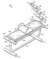
- FIG. 1is an isometric view of a preferred embodiment of the present invention.
- FIG. 2is an isometric view of a preferred embodiment of the lumbar support of the present invention.
- FIG. 3is a cutaway view of a preferred embodiment of the lumbar support of the present invention.
- FIG. 4is a plan view from the underside of a preferred embodiment of the lumbar support of the present invention.
- FIG. 5is an elevation view of a preferred embodiment of the lumbar support attached to the support frame of the present invention.
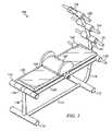
- FIG. 6is an elevation view of a preferred embodiment of the present invention shown at an in incline.
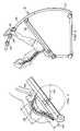
- FIG. 7is an elevation view of a preferred embodiment of the present invention showing the legs-up movement.
- FIG. 8is an isometric view of a preferred embodiment of the lumbar support attached to a fitness machine
- FIG. 9is an illustration of the spinal position during a sit-up movement performed on a flat surface.
- abdominal exercise apparatus 100is comprised of a frame, a bench, a lumbar support, and a plurality of foot rests.
- the frame of abdominal exercise apparatus 100is constructed of hollow tubular steel or aluminum approximately 1 ⁇ 8 inch thick and approximately two inches in diameter.
- Frame base 114extends between foot 110 and foot 112 and connects to each at generally perpendicular angles forming the foundation of abdominal exercise apparatus 100 .
- One end of frame brace 116connects to foot 110 and extends perpendicularly from the floor.
- the opposite end of frame brace 116forms hinge 130 .
- Frame end 140rotates inside of hinge 130 and connects to frame rail 106 and frame rail 108 .
- the opposite ends of frame rails 106 and 108connect to frame end 142 .
- Foot rest 128extends from both ends of frame end 142 .
- Incline support 118connects to foot 112 and extends from foot 112 in an arc shape.
- Incline support 118slides inside incline housing 120 .
- Incline housing 120arcs with the same radius as incline support 118 to ensure unhindered travel of incline support 118 .
- the radius of the arcs forming the shape of incline support 118 and incline housing 120is approximately the length of frame rails 106 and 108 .
- Incline housing 120further includes incline pin 132 and foot rests 122 , 124 , and 126 .
- incline pin 132is approximately 1 ⁇ 2 inch in diameter and is removably secured to incline housing 120 through a hole and collar (not shown). Incline pin 132 fits through incline housing 120 and into one of a plurality of equally spaced holes bored into incline support 118 at different heights. Foot rests 122 , 124 , 126 , and 128 are covered foam padding in the preferred embodiment. Foot rest 122 is located approximately at the midpoint of incline housing 120 . Foot rest 126 is located near the end of incline housing 120 and foot rest 124 is located in between and equidistant from foot rest 122 and 126 . In a preferred embodiment, the distance between foot rests may range between eight and twelve inches.
- Bench 104is a generally rectangular shaped and padded as is known in the art. Bench 104 is supported by and attached to two additional frame rails (not shown) which connect to frame ends 140 and 142 . Spinal flexor 102 rests on the top surface of bench 104 and is slidably attached to frame rails 106 and 108 .
- spinal flexor 102includes an arching support surface, two width extending supports, and a frame.
- Support surface 202is comprised of an inner shell formed from a semi-rigid material.
- the shell of support surface 202is covered by a padding layer and a durable cover layer.
- the padding layermay be polyethylene closed cell foam or polyurethane open cell foam with an indent load deflection value ranging from 1.8 to 3.5.
- the durable cover layermay be plastic, vinyl, leather, or some synthetic leather that can withstand frequent use.
- Support surface 202has a radius slightly greater than ordinary spinal arching. Ordinary spinal arching for the lumbar section of the spine typically has a radius in the range of 9.4 inches to 9.8 inches.
- the cylindrical shape of spinal flexor 102has a radius in the range of 9.5 to eleven inches.
- Support surface 202sits on top of and attaches to frame 208 .
- the components of frame 208 to be discussed laterare assembled using assembly screws 226 and 227 .
- Guide braces 222 and 224connect to frame 208 at generally perpendicular angles and extend below frame 208 .
- Adjustment guide 214connects to both guide braces 222 and 224 at a generally perpendicular angle.
- Adjustment guide 216attaches similarly to another pair of guide braces on the opposite side of frame 208 .
- Adjustment guide 214includes adjustment knob 220 that is affixed to adjustment pin 218 .
- Adjustment pin 218is threaded and is seated in a threaded hole in the side of adjustment guide 214 .
- Extensions 204 and 206are generally semicircular shaped members situated on either side of support surface 202 . Extensions 204 and 206 are approximately one inch thick and formed of the same material as support surface 202 . Extensions 204 and 206 each have a padding layer on the side adjacent to support surface 202 and a durable cover layer all around.
- Extension 204includes drive shaft hole 228 through which drive shaft 210 extends.
- Drive shaft 210includes drive shaft knob 212 attached to an end.
- FIG. 3is an elevation view of spinal flexor 102 showing the generally semicircular shape of extension 204 and the arc shape of support surface 202 .
- the surface of extension 204 adjacent to support surface 202includes guide rod hole 230 , guide rod hole 232 , and extension rod hole 234 .
- Drive shaft hole 228passes completely through extension 204 .
- each frame end and cross braceis made of hollow hardened plastic, aluminum or steel ranging in thickness from 1/16 inch to 1 ⁇ 8 inch and a rectangular approximate one inch by one-half inch cross section.
- Cross braces 420 , 422 , 424 , and 426are precisely machined parts. The holes bored through each must be concentrically aligned for the guide rods and extension rods to simultaneously slide through each unencumbered.
- Each hole bored through cross braces 420 , 422 , 424 , and 426includes a copper or brass bushing to ensure smooth functionality.
- Frame ends 402 and 404are connected to the cross braces using assembly screws 226 and 227 .
- An assembled frame 208is attached to support surface 202 with screws through attachment holes 464 and 466 in frame ends 402 and 404 respectively.
- the length of frame ends 402 and 404(which corresponds to the width of bench 104 ) ranges from twelve to fourteen inches while the length of cross braces 420 , 422 , 424 , and 426 ranges from nine to eleven inches.
- Guide rod 406fits into guide rod hole 230 of extension 204 .
- Guide rod 408fits into guide rod hole 232 of extension 204 .
- Extension rod 414fits into extension rod hole 234 of extension 204 .
- Drive shaft 210fits through extension 204 via drive shaft hole 228 .
- Drive shaft hole 228is fitted with bushing 430 to ensure smooth passage.
- Guide rod 410fits into guide rod hole 231 of extension 206 .
- Guide rod 412fits into guide rod hole 233 of extension 206 .
- Extension rod 416fits into extension rod hole 235 of extension 206 .
- each guide rod and each extension rodis approximately 1 ⁇ 2 inch in diameter, threaded on both ends and tightened in a respective threaded hole in the corresponding extension.
- each guide rod and extension rodmay be 1 ⁇ 2 inch by 1 ⁇ 2 inch square rods with rounded and threaded ends.
- nuts 451 , 452 , 453 , and 454are nuts 451 , 452 , 453 , and 454 respectively.
- all guide rodsmay be bolts with a bolt head on one end and threaded on the other for insertion into the extensions.
- Drive shaft 210has a diameter approximately 1 ⁇ 2 inch except for thread sections 440 and 441 .
- Thread sections 440 and 441have a diameter approximately equal to one inch and each section is approximately two inches long. Thread sections 440 and 441 are threaded in opposite directions; one being a right-handed thread and the other being the opposite.
- Thread section 440begins approximately one inch from the end of drive shaft 210 opposite drive shaft knob 212 .
- Thread section 441is approximately two inches apart from thread section 440 .
- the end of drive shaft 210 opposite drive shaft knob 212includes hole 462 through its diameter.
- Cotter pin 460fits through hole 462 .
- Washer 468fits on drive shaft 210 between thread section 440 and cross brace 424 .
- Washer 469fits on drive shaft 210 between thread section 441 and cross brace 422 .
- rack section 434includes rack section 434 .
- Rack section 434begins on the end of extension rod 414 opposite the end inserted in extension 204 .
- Rack section 434has a length of approximately four inches.
- Rack section 434includes cut grooves designed to mesh with thread section 441 of drive shaft 210 .
- rack section 436includes rack section 436 .
- Rack section 436begins on the end of extension rod 416 opposite the end inserted in extension 206 .
- Rack section 436also has a length of approximately four inches.
- Rack section 436includes grooves designed to mesh with thread section 440 of drive shaft 210 .
- the radius of the arc of support surface 202is shown as 502 .
- Radius 502is slightly larger than the normal resting position radius of the curvature of the spinal lumbar section.
- Peak distance 504represents the height of support surface 202 from the top surface of bench 104 .
- Spinal flexor length 506is the length of spinal flexor 102 . The measurements of radius 502 , peak distance 504 , and spinal flexor length 506 maintain a relationship to one another. Each can vary, but once two are fixed, the other can no longer vary.
- radius 502ranges between about 9.5 inches to about eleven inches
- peak distance 504ranges from approximately two to four inches
- spinal flexor length 506ranges between about ten to about fourteen inches.
- the lumbar section of an average height adult male or femaleis properly extended using a radius 502 equal to about ten inches and a spinal flexor length 506 of about twelve inches.
- peak distance 504is calculated to be about three inches.
- the Pythagorean theoremis used to calculate the relationship:
- cis known as support surface arc radius 502 and in this example is equal to ten inches.
- ais known as half of spinal flexor length 506 and in this example is equal to half of twelve inches or six inches.
- bis calculated to be eight inches which leaves the height of the arc section in the above figure to be (ten minus eight) inches or two inches. Adding in the one inch height of frame 208 (shown as the dashed rectangle above), peak distance 504 is calculated to be three inches total.
- FIGS. 5 and 6show the starting position ( FIG. 5 ) and the near finishing position ( FIG. 6 ) for a sit-up movement using abdominal exercise apparatus 100 .
- the starting positiontightens and stretches all the muscles of the front torso producing a direct connection between the abdominal muscles, the chest muscles, and the neck muscles to pull up the torso as one piece and prevent negative stresses to the spine.
- the starting positionalso fully extends and decompresses the lumbar section of the spine before the movement.
- the lumbar muscles of the backare neutralized. Fully extending the spine at the beginning of the movement not only helps to restore proper intervertebral space, but also prevents the pelvis from abnormally tilting so the torso is free to pivot at the hip joint.
- the finishing positionoccurs where the gravitational pull on the torso is neutralized by the torso's generally upright position relative to the floor.
- FIGS. 5 and 6show bench 104 at an incline.
- a usermay perform the movement on bench 104 without an incline or an incline of a different degree.
- incline pin 132is disengaged and the arc shaped incline housing 120 is moved through the length of the arc shaped incline support 118 .
- Bench 104 and the attached incline housing 120rotate about frame end 140 .
- Frame end 140is seated in hinge 130 .
- incline pin 132is reengaged through incline housing 120 and into one of the several bored holes along the length of incline support 118 .
- incline support 118includes four holes (not shown) to position bench 104 at four different incline angles of 0°, 15°, 30°, and 45° from the horizontal plane defined by foot 110 and foot 112 .
- Foot rests 122 , 124 , and 126are provided to allow the user to elevate the position of their feet even further. As the height of a user's feet increases, either through inclination of bench 104 , the use of the foot rests, or a combination of both, the distance the torso moves and subsequently the difficulty of the movement increases.
- the position of spinal flexor 102may be adjusted along the length of bench 104 .
- Spinal flexor 102may be moved further from incline housing 120 to adjust for larger legs.
- Spinal flexor 102may be closer to incline housing 120 as shown in FIG. 7 for a legs-up movement.
- Spinal flexor 102is held in place by rotating adjustment pin knob 220 until adjustment pin 218 comes in contact with frame rail 106 and then tightening the knob until friction between the pin and the rail hold a fixed position.
- Adjusting the longitudinal position of spinal flexor 102begins by rotating adjustment pin knob 220 in a counter-clockwise direction disengaging adjustment pin 218 from direct contact with frame rail 106 . Sliding spinal flexor 102 along frame rails 106 and 108 to the desired location and re-tightening adjustment pin 218 until it securely contacts frame rail 106 completes the longitudinal adjustment.
- the width of spinal flexor 102may be adjusted to accommodate different sized torsos.
- Extensions 204 and 206each may be adjusted approximately two inches from their starting positions.
- Rotating driveshaft 210 via driveshaft knob 212simultaneously moves both extensions 204 and 206 inward or outward depending on the direction of rotation.
- Nuts 451 , 452 , 453 , and 454 secured to the ends of guide rods 406 , 408 , 410 , and 412respectively restrict the amount of width adjustment and prevent extensions 204 and 206 from becoming disengaged from frame 208 .
- the threads of thread sections 440 and 441 on driveshaft 210engage rack section 436 of extension rod 416 and rack section 434 of extension rod 414 simultaneously.
- the userIn use, the user first sets the angle of inclination of bench 104 . A more dramatic incline increases the difficulty of the movement. Next the user adjusts the longitudinal position of spinal flexor 102 . The correct longitudinal position along bench 104 situates the pelvis of the user in the crease created between spinal flexor 102 and bench 104 while allowing the legs of the user to be comfortably bent. Next the user adjusts the width of spinal flexor 102 to accommodate a particular body size. With the feet supported by a foot rest or positioned flatly on bench 104 , the user lays back over spinal flexor 102 in the supine position.
- Spinal flexor 102supports the lumbar section of the user's spine, prevents the pelvis from abnormally tilting, and creates a pivot point at the pelvis of the user.
- the starting positionstretches all the front muscles of the torso including the abdominals and the chest and neck muscles in preparation for the movement. In addition to neutralizing the lumbar muscles of the back, the starting position also fully extends and decompresses the lumbar section of the spine.
- spinal flexor 102acting as a fulcrum, the torso pivots at the pelvis as the front muscles of the torso contract safeguarding the natural curvature of the spine and preventing negative stresses on the spine.
- a useris shown performing a legs-up movement on abdominal exercise apparatus 100 .
- Extensions 204 and 206are not pictured to demonstrate the user's position relative to spinal flexor 102 .
- the spineremains relatively stationary.
- the muscles of the thighinitiate the movement and pass it subsequently to the abdominal muscles until the legs reach a completely vertical position.
- Spinal flexor 102again fully extends the lumbar section of the spine, stretches the front muscles of the torso, neutralizes the lumbar muscles, and acts as a fulcrum for the legs to pivot at the user's pelvis.
- FIG. 8shows a vertical application of spinal flexor 102 complete with vertical adjustment 802 and lateral adjustment 804 .
- a usermoves an adjustable stack of weights 806 by virtue of a pulley system 810 .
- spinal flexor 102stretches the front muscles of the torso and fully extends the lumbar section of the spine before the movement begins.
- the vertical applicationprevents negative stresses on the spine by supporting the spine prior to the movement and stabilizing the spine during the movement.
- a belt 812 or tie-downmay be utilized by the user to keep the body secure to spinal flexor 102 thereby ensuring spinal flexor 102 supports the spine and is used as a fulcrum for the pelvis to pivot about.
Landscapes
- Health & Medical Sciences (AREA)
- Orthopedic Medicine & Surgery (AREA)
- General Health & Medical Sciences (AREA)
- Physical Education & Sports Medicine (AREA)
- Engineering & Computer Science (AREA)
- Biomedical Technology (AREA)
- Neurology (AREA)
- Pulmonology (AREA)
- Life Sciences & Earth Sciences (AREA)
- Biophysics (AREA)
- Orthopedics, Nursing, And Contraception (AREA)
Abstract
Description

Claims (13)
Priority Applications (1)
| Application Number | Priority Date | Filing Date | Title |
|---|---|---|---|
| US12/386,488US7691042B2 (en) | 2004-11-29 | 2007-08-24 | Abdominal exercising apparatus and method |
Applications Claiming Priority (2)
| Application Number | Priority Date | Filing Date | Title |
|---|---|---|---|
| US10/998,875US20060116262A1 (en) | 2004-11-29 | 2004-11-29 | Biodynamic apparatus for performing correct SIT-UP and LEGS-UP exercises and methods |
| US12/386,488US7691042B2 (en) | 2004-11-29 | 2007-08-24 | Abdominal exercising apparatus and method |
Related Parent Applications (1)
| Application Number | Title | Priority Date | Filing Date |
|---|---|---|---|
| US10/998,875Continuation-In-PartUS20060116262A1 (en) | 2004-11-29 | 2004-11-29 | Biodynamic apparatus for performing correct SIT-UP and LEGS-UP exercises and methods |
Publications (2)
| Publication Number | Publication Date |
|---|---|
| US20090305856A1 US20090305856A1 (en) | 2009-12-10 |
| US7691042B2true US7691042B2 (en) | 2010-04-06 |
Family
ID=41400849
Family Applications (1)
| Application Number | Title | Priority Date | Filing Date |
|---|---|---|---|
| US12/386,488Expired - Fee RelatedUS7691042B2 (en) | 2004-11-29 | 2007-08-24 | Abdominal exercising apparatus and method |
Country Status (1)
| Country | Link |
|---|---|
| US (1) | US7691042B2 (en) |
Cited By (20)
| Publication number | Priority date | Publication date | Assignee | Title |
|---|---|---|---|---|
| US20090227435A1 (en)* | 2008-03-07 | 2009-09-10 | Raffaele Martini Pandozy | Horizontal rotary torso exercising apparatus and method |
| US20100222192A1 (en)* | 2009-02-27 | 2010-09-02 | Harris Robert W | Stretching and toning device |
| US20120122637A1 (en)* | 2010-11-16 | 2012-05-17 | Chad Bathey | Core Exercise Device |
| US20130008452A1 (en)* | 2011-06-30 | 2013-01-10 | Steven Evangelos | Training and Rehabilitation Device |
| US20130225378A1 (en)* | 2012-02-16 | 2013-08-29 | Denis E Burek | Leg Stretching Machine For Simultaneously Stretching All Stride Muscles And Method Of Using |
| KR101302997B1 (en)* | 2011-12-26 | 2013-09-06 | 김영미 | Sit-up exercise device |
| USD730458S1 (en)* | 2013-12-12 | 2015-05-26 | Zhejiang University | Folding fitness chair |
| US9192801B1 (en)* | 2009-12-08 | 2015-11-24 | Vassili Gouloubev | Exercise support system |
| US20150367168A1 (en)* | 2014-05-23 | 2015-12-24 | Coulter Ventures, Llc, D/B/A Rogue Fitness | Rack-mounted glute-ham developer and method for making the same |
| WO2018101637A1 (en)* | 2016-11-30 | 2018-06-07 | 강정모 | Bicycle-type total body exercise device |
| US10188890B2 (en) | 2013-12-26 | 2019-01-29 | Icon Health & Fitness, Inc. | Magnetic resistance mechanism in a cable machine |
| US10252109B2 (en) | 2016-05-13 | 2019-04-09 | Icon Health & Fitness, Inc. | Weight platform treadmill |
| US10279212B2 (en) | 2013-03-14 | 2019-05-07 | Icon Health & Fitness, Inc. | Strength training apparatus with flywheel and related methods |
| US10293211B2 (en) | 2016-03-18 | 2019-05-21 | Icon Health & Fitness, Inc. | Coordinated weight selection |
| US10420974B2 (en)* | 2013-07-03 | 2019-09-24 | Coulter Ventures | Exercise device |
| US10426989B2 (en) | 2014-06-09 | 2019-10-01 | Icon Health & Fitness, Inc. | Cable system incorporated into a treadmill |
| US10441840B2 (en) | 2016-03-18 | 2019-10-15 | Icon Health & Fitness, Inc. | Collapsible strength exercise machine |
| US10449416B2 (en) | 2015-08-26 | 2019-10-22 | Icon Health & Fitness, Inc. | Strength exercise mechanisms |
| US10661114B2 (en) | 2016-11-01 | 2020-05-26 | Icon Health & Fitness, Inc. | Body weight lift mechanism on treadmill |
| US10940360B2 (en) | 2015-08-26 | 2021-03-09 | Icon Health & Fitness, Inc. | Strength exercise mechanisms |
Families Citing this family (9)
| Publication number | Priority date | Publication date | Assignee | Title |
|---|---|---|---|---|
| US8556787B2 (en)* | 2011-09-02 | 2013-10-15 | Expectations, LLC | Tilting inversion exerciser |
| US9259604B2 (en)* | 2012-08-31 | 2016-02-16 | Elwood Bernard Miller, Jr. | Exercise machine for performing squats |
| CN102861421A (en)* | 2012-10-21 | 2013-01-09 | 严斌 | Sit-up fitness device |
| US10518129B2 (en)* | 2013-01-10 | 2019-12-31 | The Board Of Regents Of The University Of Texas System | Stretching machine |
| IE20140065A1 (en)* | 2014-03-11 | 2015-09-23 | Noel Doherty | Exercise equipment for the performance of hamstring eccentric and concentric exercise |
| CN106983996A (en)* | 2017-04-14 | 2017-07-28 | 广东梯客悦野体育科技有限公司 | An abdominal muscle wheel device capable of changing fitness intensity |
| US10814158B2 (en)* | 2017-10-24 | 2020-10-27 | Mancias Management Group, LLC | Weightlifting bench |
| CN108525212A (en)* | 2018-04-14 | 2018-09-14 | 江西师范大学 | Abdominal muscle exercising device |
| KR102071893B1 (en)* | 2018-08-12 | 2020-02-03 | 김대승 | Combined fitness equipment for squat and romantic chair exercise |
Citations (52)
| Publication number | Priority date | Publication date | Assignee | Title |
|---|---|---|---|---|
| US1904039A (en)* | 1930-10-27 | 1933-04-18 | Emil A Bruder | Body exercising apparatus |
| US2159654A (en)* | 1936-10-06 | 1939-05-23 | De Forest B Catlin | Osteopathic apparatus for treatment of the back |
| US2264046A (en)* | 1940-10-22 | 1941-11-25 | Garriott L Mcclellan | Exercising device |
| US3102280A (en)* | 1961-10-10 | 1963-09-03 | Frederick F Williams | Buoyant exercising device or toy |
| US4190286A (en)* | 1977-12-02 | 1980-02-26 | Bentley John P | Inflatable seat cushion and body support assembly |
| US4210322A (en)* | 1977-10-03 | 1980-07-01 | Pritchard Michael E | Portable tumbling mat |
| USD267028S (en)* | 1980-03-24 | 1982-11-23 | Spisak Mathew V | Exercise board |
| US4372553A (en)* | 1980-11-03 | 1983-02-08 | Hatfield Frederick C | Weight lifting device and method of exercising |
| US4474370A (en)* | 1982-11-12 | 1984-10-02 | Oman Kim W | Therapeutic weightlifter's bench |
| USD284394S (en)* | 1983-03-22 | 1986-06-24 | Bengtson Lars G F | Abdominal muscle trainer |
| US4796315A (en)* | 1986-01-27 | 1989-01-10 | Crew Randolph E | Rotationally contoured lumbar cushion |
| US4867142A (en)* | 1988-02-12 | 1989-09-19 | Prd Corporation | Self actuated lombar traction apparatus |
| US4953857A (en)* | 1989-07-27 | 1990-09-04 | Lemire Brett J | Orthopedic back support attachment for a weight lifter's bench |
| US5007633A (en)* | 1989-07-27 | 1991-04-16 | Lemire Brett J | Spinal column support attachments for a weight lifter's bench |
| US5110122A (en)* | 1990-09-14 | 1992-05-05 | Czeu Gathright | Exercising apparatus and method |
| US5304109A (en)* | 1993-01-22 | 1994-04-19 | Shockley Ronnie W | Inflatable support |
| US5447481A (en)* | 1994-03-03 | 1995-09-05 | Emter, Jr.; James | Bench press exercise apparatus |
| US5549534A (en)* | 1989-02-07 | 1996-08-27 | Parviainen; Arno | Spine rehabilitation apparatus |
| US5584786A (en)* | 1993-07-07 | 1996-12-17 | Almeda; Thomas M. | Abdominal exercise device |
| US5722923A (en)* | 1995-08-08 | 1998-03-03 | Lui; Herman | Device for abdominal muscle exercise |
| US5755647A (en)* | 1995-05-16 | 1998-05-26 | Lawrence I. Wechsler | Exercise appliance for abdominal muscles and method of using same |
| US5795276A (en)* | 1993-07-07 | 1998-08-18 | Almeda; T. Michael | Stretching and exercise device |
| US5931769A (en)* | 1998-07-23 | 1999-08-03 | Nunez; Luis Alberto | Exercise device |
| US5947876A (en)* | 1997-01-22 | 1999-09-07 | Willey, Ii; J. Warren | Abdominal range of motion exercise |
| US6015370A (en)* | 1997-05-29 | 2000-01-18 | Pandozy; Raffaele Martini | Combined therapeutic exercise apparatus for the back |
| US6390960B1 (en)* | 2000-08-23 | 2002-05-21 | Boland Kevin O'brien | Abdominals and hip exercise machine |
| US6422980B1 (en)* | 1999-08-23 | 2002-07-23 | Roy Simonson | Standing abdominal exercise apparatus |
| US6467841B1 (en)* | 1997-12-18 | 2002-10-22 | A & H Design Concepts, Inc. | Lumbar support |
| US20040077468A1 (en)* | 2002-03-11 | 2004-04-22 | Myles Tyrone Andree | AB crunch machine |
| US6755771B2 (en)* | 2001-03-15 | 2004-06-29 | Robert S. Wallerstein | Exercise device for exercising of the abdominal muscles |
| US20040259703A1 (en)* | 2003-06-23 | 2004-12-23 | Kim Goh | Exercise apparatus |
| US6843759B2 (en)* | 2001-03-15 | 2005-01-18 | Robert S. Wallerstein | Exercise device for exercising of the abdominal muscles |
| US6899662B2 (en)* | 2002-09-09 | 2005-05-31 | Michael L. Gamble | Contoured pad for supporting a weight-lifter on a bench |
| US6994661B1 (en)* | 2002-11-01 | 2006-02-07 | Fred Dawson | Tiltable exercise bench |
| US20060040811A1 (en)* | 2004-08-09 | 2006-02-23 | Foster Anthony L | Floor exercise mat and pad system |
| US20060116262A1 (en)* | 2004-11-29 | 2006-06-01 | Pandozy Raffaele M | Biodynamic apparatus for performing correct SIT-UP and LEGS-UP exercises and methods |
| US7060085B2 (en)* | 2003-04-08 | 2006-06-13 | Richard A. Graham | Rocking vectored pneumatic joint separator |
| US7258653B2 (en)* | 1998-02-13 | 2007-08-21 | Lee Brandon | Postural awareness apparatus |
| USD555741S1 (en)* | 2006-04-11 | 2007-11-20 | Kerry Wachtfogel | Pilates exercise apparatus |
| USD560259S1 (en)* | 2004-09-15 | 2008-01-22 | Svan Ab | Kick and balance trainer |
| US7329213B1 (en)* | 2004-03-25 | 2008-02-12 | Farley Michael D | Exercise machine with compound abdominal movement |
| US7341565B2 (en)* | 2004-04-02 | 2008-03-11 | Suncepts, Inc. | Passive motion machine providing controlled body motions for exercise and therapeutic purposes |
| US7357759B2 (en)* | 2004-06-14 | 2008-04-15 | Bonnell Loren W | Exercise device |
| US20080119338A1 (en)* | 2006-11-20 | 2008-05-22 | Jan Prsala | Body posture and physical fitness exercise device |
| US7384383B2 (en)* | 2005-10-28 | 2008-06-10 | J.E.M. Concept International, Inc. | Abdominal bench |
| USD578219S1 (en)* | 2008-01-14 | 2008-10-07 | Jonathan Daggett | Pneumatic lumbar therapy mattress |
| US7452313B2 (en)* | 2005-11-10 | 2008-11-18 | Balanced Body, Inc. | Convertible barrel exercise apparatus |
| US20090018000A1 (en)* | 2004-01-05 | 2009-01-15 | Wallace Brown | Abdominal exercise machine |
| US20090177121A1 (en)* | 1998-02-13 | 2009-07-09 | Lee Brandon | Postural awareness apparatus |
| US20090227435A1 (en)* | 2008-03-07 | 2009-09-10 | Raffaele Martini Pandozy | Horizontal rotary torso exercising apparatus and method |
| US7601109B2 (en)* | 2005-12-09 | 2009-10-13 | Gary Roumayah | Abdominal exercise device |
| US7604580B2 (en)* | 2005-05-25 | 2009-10-20 | Matthew Justin Lamarque | Exercise device and method |
- 2007
- 2007-08-24USUS12/386,488patent/US7691042B2/ennot_activeExpired - Fee Related
Patent Citations (53)
| Publication number | Priority date | Publication date | Assignee | Title |
|---|---|---|---|---|
| US1904039A (en)* | 1930-10-27 | 1933-04-18 | Emil A Bruder | Body exercising apparatus |
| US2159654A (en)* | 1936-10-06 | 1939-05-23 | De Forest B Catlin | Osteopathic apparatus for treatment of the back |
| US2264046A (en)* | 1940-10-22 | 1941-11-25 | Garriott L Mcclellan | Exercising device |
| US3102280A (en)* | 1961-10-10 | 1963-09-03 | Frederick F Williams | Buoyant exercising device or toy |
| US4210322A (en)* | 1977-10-03 | 1980-07-01 | Pritchard Michael E | Portable tumbling mat |
| US4190286A (en)* | 1977-12-02 | 1980-02-26 | Bentley John P | Inflatable seat cushion and body support assembly |
| USD267028S (en)* | 1980-03-24 | 1982-11-23 | Spisak Mathew V | Exercise board |
| US4372553A (en)* | 1980-11-03 | 1983-02-08 | Hatfield Frederick C | Weight lifting device and method of exercising |
| US4474370A (en)* | 1982-11-12 | 1984-10-02 | Oman Kim W | Therapeutic weightlifter's bench |
| USD284394S (en)* | 1983-03-22 | 1986-06-24 | Bengtson Lars G F | Abdominal muscle trainer |
| US4796315A (en)* | 1986-01-27 | 1989-01-10 | Crew Randolph E | Rotationally contoured lumbar cushion |
| US4867142A (en)* | 1988-02-12 | 1989-09-19 | Prd Corporation | Self actuated lombar traction apparatus |
| US5549534A (en)* | 1989-02-07 | 1996-08-27 | Parviainen; Arno | Spine rehabilitation apparatus |
| US4953857A (en)* | 1989-07-27 | 1990-09-04 | Lemire Brett J | Orthopedic back support attachment for a weight lifter's bench |
| US5007633A (en)* | 1989-07-27 | 1991-04-16 | Lemire Brett J | Spinal column support attachments for a weight lifter's bench |
| US5110122A (en)* | 1990-09-14 | 1992-05-05 | Czeu Gathright | Exercising apparatus and method |
| US5304109A (en)* | 1993-01-22 | 1994-04-19 | Shockley Ronnie W | Inflatable support |
| US5584786A (en)* | 1993-07-07 | 1996-12-17 | Almeda; Thomas M. | Abdominal exercise device |
| US5795276A (en)* | 1993-07-07 | 1998-08-18 | Almeda; T. Michael | Stretching and exercise device |
| US5447481A (en)* | 1994-03-03 | 1995-09-05 | Emter, Jr.; James | Bench press exercise apparatus |
| US5755647A (en)* | 1995-05-16 | 1998-05-26 | Lawrence I. Wechsler | Exercise appliance for abdominal muscles and method of using same |
| US5722923A (en)* | 1995-08-08 | 1998-03-03 | Lui; Herman | Device for abdominal muscle exercise |
| US5947876A (en)* | 1997-01-22 | 1999-09-07 | Willey, Ii; J. Warren | Abdominal range of motion exercise |
| USRE38057E1 (en)* | 1997-05-29 | 2003-04-01 | Raphaele Martini Pandozy | Combined therapeutic exercise apparatus for the back |
| US6015370A (en)* | 1997-05-29 | 2000-01-18 | Pandozy; Raffaele Martini | Combined therapeutic exercise apparatus for the back |
| US6467841B1 (en)* | 1997-12-18 | 2002-10-22 | A & H Design Concepts, Inc. | Lumbar support |
| US20090177121A1 (en)* | 1998-02-13 | 2009-07-09 | Lee Brandon | Postural awareness apparatus |
| US7258653B2 (en)* | 1998-02-13 | 2007-08-21 | Lee Brandon | Postural awareness apparatus |
| US5931769A (en)* | 1998-07-23 | 1999-08-03 | Nunez; Luis Alberto | Exercise device |
| US6422980B1 (en)* | 1999-08-23 | 2002-07-23 | Roy Simonson | Standing abdominal exercise apparatus |
| US6390960B1 (en)* | 2000-08-23 | 2002-05-21 | Boland Kevin O'brien | Abdominals and hip exercise machine |
| US6755771B2 (en)* | 2001-03-15 | 2004-06-29 | Robert S. Wallerstein | Exercise device for exercising of the abdominal muscles |
| US6843759B2 (en)* | 2001-03-15 | 2005-01-18 | Robert S. Wallerstein | Exercise device for exercising of the abdominal muscles |
| US20040077468A1 (en)* | 2002-03-11 | 2004-04-22 | Myles Tyrone Andree | AB crunch machine |
| US6899662B2 (en)* | 2002-09-09 | 2005-05-31 | Michael L. Gamble | Contoured pad for supporting a weight-lifter on a bench |
| US6994661B1 (en)* | 2002-11-01 | 2006-02-07 | Fred Dawson | Tiltable exercise bench |
| US7060085B2 (en)* | 2003-04-08 | 2006-06-13 | Richard A. Graham | Rocking vectored pneumatic joint separator |
| US20040259703A1 (en)* | 2003-06-23 | 2004-12-23 | Kim Goh | Exercise apparatus |
| US20090018000A1 (en)* | 2004-01-05 | 2009-01-15 | Wallace Brown | Abdominal exercise machine |
| US7329213B1 (en)* | 2004-03-25 | 2008-02-12 | Farley Michael D | Exercise machine with compound abdominal movement |
| US7341565B2 (en)* | 2004-04-02 | 2008-03-11 | Suncepts, Inc. | Passive motion machine providing controlled body motions for exercise and therapeutic purposes |
| US7357759B2 (en)* | 2004-06-14 | 2008-04-15 | Bonnell Loren W | Exercise device |
| US20060040811A1 (en)* | 2004-08-09 | 2006-02-23 | Foster Anthony L | Floor exercise mat and pad system |
| USD560259S1 (en)* | 2004-09-15 | 2008-01-22 | Svan Ab | Kick and balance trainer |
| US20060116262A1 (en)* | 2004-11-29 | 2006-06-01 | Pandozy Raffaele M | Biodynamic apparatus for performing correct SIT-UP and LEGS-UP exercises and methods |
| US7604580B2 (en)* | 2005-05-25 | 2009-10-20 | Matthew Justin Lamarque | Exercise device and method |
| US7384383B2 (en)* | 2005-10-28 | 2008-06-10 | J.E.M. Concept International, Inc. | Abdominal bench |
| US7452313B2 (en)* | 2005-11-10 | 2008-11-18 | Balanced Body, Inc. | Convertible barrel exercise apparatus |
| US7601109B2 (en)* | 2005-12-09 | 2009-10-13 | Gary Roumayah | Abdominal exercise device |
| USD555741S1 (en)* | 2006-04-11 | 2007-11-20 | Kerry Wachtfogel | Pilates exercise apparatus |
| US20080119338A1 (en)* | 2006-11-20 | 2008-05-22 | Jan Prsala | Body posture and physical fitness exercise device |
| USD578219S1 (en)* | 2008-01-14 | 2008-10-07 | Jonathan Daggett | Pneumatic lumbar therapy mattress |
| US20090227435A1 (en)* | 2008-03-07 | 2009-09-10 | Raffaele Martini Pandozy | Horizontal rotary torso exercising apparatus and method |
Cited By (25)
| Publication number | Priority date | Publication date | Assignee | Title |
|---|---|---|---|---|
| US7887472B2 (en)* | 2008-03-07 | 2011-02-15 | Raffaele Martini Pandozy | Horizontal rotary torso exercising apparatus and method |
| US20090227435A1 (en)* | 2008-03-07 | 2009-09-10 | Raffaele Martini Pandozy | Horizontal rotary torso exercising apparatus and method |
| US20100222192A1 (en)* | 2009-02-27 | 2010-09-02 | Harris Robert W | Stretching and toning device |
| US7942795B2 (en)* | 2009-02-27 | 2011-05-17 | Harris Robert W | Stretching and toning device |
| US9192801B1 (en)* | 2009-12-08 | 2015-11-24 | Vassili Gouloubev | Exercise support system |
| US20120122637A1 (en)* | 2010-11-16 | 2012-05-17 | Chad Bathey | Core Exercise Device |
| US8734307B2 (en)* | 2010-11-16 | 2014-05-27 | Chad Bathey | Core exercise device |
| US20130008452A1 (en)* | 2011-06-30 | 2013-01-10 | Steven Evangelos | Training and Rehabilitation Device |
| KR101302997B1 (en)* | 2011-12-26 | 2013-09-06 | 김영미 | Sit-up exercise device |
| US20130225378A1 (en)* | 2012-02-16 | 2013-08-29 | Denis E Burek | Leg Stretching Machine For Simultaneously Stretching All Stride Muscles And Method Of Using |
| US10279212B2 (en) | 2013-03-14 | 2019-05-07 | Icon Health & Fitness, Inc. | Strength training apparatus with flywheel and related methods |
| US10420974B2 (en)* | 2013-07-03 | 2019-09-24 | Coulter Ventures | Exercise device |
| USD730458S1 (en)* | 2013-12-12 | 2015-05-26 | Zhejiang University | Folding fitness chair |
| US10188890B2 (en) | 2013-12-26 | 2019-01-29 | Icon Health & Fitness, Inc. | Magnetic resistance mechanism in a cable machine |
| US20160045780A1 (en)* | 2014-05-23 | 2016-02-18 | Coulter Ventures, LLC | Glute Ham Developer |
| US9669255B2 (en)* | 2014-05-23 | 2017-06-06 | Coulter Ventures, LLC | Glute ham developer |
| US20150367168A1 (en)* | 2014-05-23 | 2015-12-24 | Coulter Ventures, Llc, D/B/A Rogue Fitness | Rack-mounted glute-ham developer and method for making the same |
| US10426989B2 (en) | 2014-06-09 | 2019-10-01 | Icon Health & Fitness, Inc. | Cable system incorporated into a treadmill |
| US10449416B2 (en) | 2015-08-26 | 2019-10-22 | Icon Health & Fitness, Inc. | Strength exercise mechanisms |
| US10940360B2 (en) | 2015-08-26 | 2021-03-09 | Icon Health & Fitness, Inc. | Strength exercise mechanisms |
| US10293211B2 (en) | 2016-03-18 | 2019-05-21 | Icon Health & Fitness, Inc. | Coordinated weight selection |
| US10441840B2 (en) | 2016-03-18 | 2019-10-15 | Icon Health & Fitness, Inc. | Collapsible strength exercise machine |
| US10252109B2 (en) | 2016-05-13 | 2019-04-09 | Icon Health & Fitness, Inc. | Weight platform treadmill |
| US10661114B2 (en) | 2016-11-01 | 2020-05-26 | Icon Health & Fitness, Inc. | Body weight lift mechanism on treadmill |
| WO2018101637A1 (en)* | 2016-11-30 | 2018-06-07 | 강정모 | Bicycle-type total body exercise device |
Also Published As
| Publication number | Publication date |
|---|---|
| US20090305856A1 (en) | 2009-12-10 |
Similar Documents
| Publication | Publication Date | Title |
|---|---|---|
| US7691042B2 (en) | Abdominal exercising apparatus and method | |
| US7485079B2 (en) | Abdominal exercise machine | |
| US7455633B2 (en) | Abdominal exerciser device | |
| US5746688A (en) | Exercise device | |
| US7232404B2 (en) | Abdominal exercise machine | |
| US8062196B1 (en) | Abdominal exercise apparatus | |
| US7585263B2 (en) | Abdominal exercise machine | |
| US6186926B1 (en) | Seated abdominal exercise machine | |
| US7611445B2 (en) | Abdominal exercise machine | |
| AU2003264721B2 (en) | Exercise apparatus | |
| US5616107A (en) | Method and apparatus for leg press exercise with counterbalance | |
| US7887472B2 (en) | Horizontal rotary torso exercising apparatus and method | |
| US7311645B1 (en) | Abdominal exercise machine | |
| US5556363A (en) | Linear movement, trunk muscle exercise method | |
| US20060229177A1 (en) | Exercise Ball Mounted for Rotation | |
| JP2010511425A5 (en) | ||
| US20060116262A1 (en) | Biodynamic apparatus for performing correct SIT-UP and LEGS-UP exercises and methods | |
| US8177695B2 (en) | Abdominal training machine and method | |
| EP2537564B1 (en) | Foot, leg, and arm support for exercise | |
| US9192801B1 (en) | Exercise support system | |
| US20030092543A1 (en) | Upper torso exercise machine | |
| US7666123B2 (en) | Upper torso exercise machine | |
| US11648435B2 (en) | Exercise machine and methods of use for strengthening the lumbopelvic complex | |
| US11213717B2 (en) | Power rowing machine with pivoting weight arm | |
| US7297095B2 (en) | Rotary torso exercise bench |
Legal Events
| Date | Code | Title | Description |
|---|---|---|---|
| AS | Assignment | Owner name:IDEAS FOR SALE, INC.,TEXAS Free format text:ASSIGNMENT OF ASSIGNORS INTEREST;ASSIGNOR:PANDOZY, RAFFAELE M.;REEL/FRAME:022793/0759 Effective date:20060703 Owner name:IDEAS FOR SALE, INC., TEXAS Free format text:ASSIGNMENT OF ASSIGNORS INTEREST;ASSIGNOR:PANDOZY, RAFFAELE M.;REEL/FRAME:022793/0759 Effective date:20060703 | |
| AS | Assignment | Owner name:CORE FITNESS SYSTEM INC., TEXAS Free format text:ASSIGNMENT OF ASSIGNORS INTEREST;ASSIGNOR:TAOLO M SPEDICATO IDEAS FOR SALE INC.;REEL/FRAME:027473/0110 Effective date:20111031 Owner name:CORE FITNESS SYSTEM INC., TEXAS Free format text:ASSIGNMENT OF ASSIGNORS INTEREST;ASSIGNOR:PAOLO M SPEDICATO IDEAS FOR SALE INC.;REEL/FRAME:027473/0110 Effective date:20111031 | |
| FEPP | Fee payment procedure | Free format text:PETITION RELATED TO MAINTENANCE FEES GRANTED (ORIGINAL EVENT CODE: PMFG); ENTITY STATUS OF PATENT OWNER: MICROENTITY | |
| REMI | Maintenance fee reminder mailed | ||
| FEPP | Fee payment procedure | Free format text:PETITION RELATED TO MAINTENANCE FEES FILED (ORIGINAL EVENT CODE: PMFP); ENTITY STATUS OF PATENT OWNER: MICROENTITY | |
| FEPP | Fee payment procedure | Free format text:PETITION RELATED TO MAINTENANCE FEES DISMISSED (ORIGINAL EVENT CODE: PMFS); ENTITY STATUS OF PATENT OWNER: MICROENTITY | |
| FEPP | Fee payment procedure | Free format text:PETITION RELATED TO MAINTENANCE FEES FILED (ORIGINAL EVENT CODE: PMFP); ENTITY STATUS OF PATENT OWNER: MICROENTITY | |
| LAPS | Lapse for failure to pay maintenance fees | ||
| REIN | Reinstatement after maintenance fee payment confirmed | ||
| FP | Lapsed due to failure to pay maintenance fee | Effective date:20140406 | |
| FPAY | Fee payment | Year of fee payment:4 | |
| PRDP | Patent reinstated due to the acceptance of a late maintenance fee | Effective date:20141215 | |
| FEPP | Fee payment procedure | Free format text:MAINTENANCE FEE REMINDER MAILED (ORIGINAL EVENT CODE: REM.) | |
| LAPS | Lapse for failure to pay maintenance fees | Free format text:PATENT EXPIRED FOR FAILURE TO PAY MAINTENANCE FEES (ORIGINAL EVENT CODE: EXP.) | |
| STCH | Information on status: patent discontinuation | Free format text:PATENT EXPIRED DUE TO NONPAYMENT OF MAINTENANCE FEES UNDER 37 CFR 1.362 | |
| FP | Lapsed due to failure to pay maintenance fee | Effective date:20180406 |