US7691026B2 - Control architecture for optimization and control of a hybrid powertrain system - Google Patents
Control architecture for optimization and control of a hybrid powertrain systemDownload PDFInfo
- Publication number
- US7691026B2 US7691026B2US11/561,140US56114006AUS7691026B2US 7691026 B2US7691026 B2US 7691026B2US 56114006 AUS56114006 AUS 56114006AUS 7691026 B2US7691026 B2US 7691026B2
- Authority
- US
- United States
- Prior art keywords
- torque
- transmission
- operating range
- range state
- engine
- Prior art date
- Legal status (The legal status is an assumption and is not a legal conclusion. Google has not performed a legal analysis and makes no representation as to the accuracy of the status listed.)
- Active, expires
Links
Images


Classifications
- B—PERFORMING OPERATIONS; TRANSPORTING
- B60—VEHICLES IN GENERAL
- B60K—ARRANGEMENT OR MOUNTING OF PROPULSION UNITS OR OF TRANSMISSIONS IN VEHICLES; ARRANGEMENT OR MOUNTING OF PLURAL DIVERSE PRIME-MOVERS IN VEHICLES; AUXILIARY DRIVES FOR VEHICLES; INSTRUMENTATION OR DASHBOARDS FOR VEHICLES; ARRANGEMENTS IN CONNECTION WITH COOLING, AIR INTAKE, GAS EXHAUST OR FUEL SUPPLY OF PROPULSION UNITS IN VEHICLES
- B60K6/00—Arrangement or mounting of plural diverse prime-movers for mutual or common propulsion, e.g. hybrid propulsion systems comprising electric motors and internal combustion engines
- B60K6/20—Arrangement or mounting of plural diverse prime-movers for mutual or common propulsion, e.g. hybrid propulsion systems comprising electric motors and internal combustion engines the prime-movers consisting of electric motors and internal combustion engines, e.g. HEVs
- B60K6/22—Arrangement or mounting of plural diverse prime-movers for mutual or common propulsion, e.g. hybrid propulsion systems comprising electric motors and internal combustion engines the prime-movers consisting of electric motors and internal combustion engines, e.g. HEVs characterised by apparatus, components or means specially adapted for HEVs
- B60K6/36—Arrangement or mounting of plural diverse prime-movers for mutual or common propulsion, e.g. hybrid propulsion systems comprising electric motors and internal combustion engines the prime-movers consisting of electric motors and internal combustion engines, e.g. HEVs characterised by apparatus, components or means specially adapted for HEVs characterised by the transmission gearings
- B60K6/365—Arrangement or mounting of plural diverse prime-movers for mutual or common propulsion, e.g. hybrid propulsion systems comprising electric motors and internal combustion engines the prime-movers consisting of electric motors and internal combustion engines, e.g. HEVs characterised by apparatus, components or means specially adapted for HEVs characterised by the transmission gearings with the gears having orbital motion
- B—PERFORMING OPERATIONS; TRANSPORTING
- B60—VEHICLES IN GENERAL
- B60W—CONJOINT CONTROL OF VEHICLE SUB-UNITS OF DIFFERENT TYPE OR DIFFERENT FUNCTION; CONTROL SYSTEMS SPECIALLY ADAPTED FOR HYBRID VEHICLES; ROAD VEHICLE DRIVE CONTROL SYSTEMS FOR PURPOSES NOT RELATED TO THE CONTROL OF A PARTICULAR SUB-UNIT
- B60W20/00—Control systems specially adapted for hybrid vehicles
- B60W20/30—Control strategies involving selection of transmission gear ratio
- B—PERFORMING OPERATIONS; TRANSPORTING
- B60—VEHICLES IN GENERAL
- B60K—ARRANGEMENT OR MOUNTING OF PROPULSION UNITS OR OF TRANSMISSIONS IN VEHICLES; ARRANGEMENT OR MOUNTING OF PLURAL DIVERSE PRIME-MOVERS IN VEHICLES; AUXILIARY DRIVES FOR VEHICLES; INSTRUMENTATION OR DASHBOARDS FOR VEHICLES; ARRANGEMENTS IN CONNECTION WITH COOLING, AIR INTAKE, GAS EXHAUST OR FUEL SUPPLY OF PROPULSION UNITS IN VEHICLES
- B60K6/00—Arrangement or mounting of plural diverse prime-movers for mutual or common propulsion, e.g. hybrid propulsion systems comprising electric motors and internal combustion engines
- B60K6/20—Arrangement or mounting of plural diverse prime-movers for mutual or common propulsion, e.g. hybrid propulsion systems comprising electric motors and internal combustion engines the prime-movers consisting of electric motors and internal combustion engines, e.g. HEVs
- B60K6/42—Arrangement or mounting of plural diverse prime-movers for mutual or common propulsion, e.g. hybrid propulsion systems comprising electric motors and internal combustion engines the prime-movers consisting of electric motors and internal combustion engines, e.g. HEVs characterised by the architecture of the hybrid electric vehicle
- B60K6/44—Series-parallel type
- B60K6/445—Differential gearing distribution type
- B—PERFORMING OPERATIONS; TRANSPORTING
- B60—VEHICLES IN GENERAL
- B60K—ARRANGEMENT OR MOUNTING OF PROPULSION UNITS OR OF TRANSMISSIONS IN VEHICLES; ARRANGEMENT OR MOUNTING OF PLURAL DIVERSE PRIME-MOVERS IN VEHICLES; AUXILIARY DRIVES FOR VEHICLES; INSTRUMENTATION OR DASHBOARDS FOR VEHICLES; ARRANGEMENTS IN CONNECTION WITH COOLING, AIR INTAKE, GAS EXHAUST OR FUEL SUPPLY OF PROPULSION UNITS IN VEHICLES
- B60K6/00—Arrangement or mounting of plural diverse prime-movers for mutual or common propulsion, e.g. hybrid propulsion systems comprising electric motors and internal combustion engines
- B60K6/20—Arrangement or mounting of plural diverse prime-movers for mutual or common propulsion, e.g. hybrid propulsion systems comprising electric motors and internal combustion engines the prime-movers consisting of electric motors and internal combustion engines, e.g. HEVs
- B60K6/50—Architecture of the driveline characterised by arrangement or kind of transmission units
- B60K6/54—Transmission for changing ratio
- B60K6/547—Transmission for changing ratio the transmission being a stepped gearing
- B—PERFORMING OPERATIONS; TRANSPORTING
- B60—VEHICLES IN GENERAL
- B60W—CONJOINT CONTROL OF VEHICLE SUB-UNITS OF DIFFERENT TYPE OR DIFFERENT FUNCTION; CONTROL SYSTEMS SPECIALLY ADAPTED FOR HYBRID VEHICLES; ROAD VEHICLE DRIVE CONTROL SYSTEMS FOR PURPOSES NOT RELATED TO THE CONTROL OF A PARTICULAR SUB-UNIT
- B60W10/00—Conjoint control of vehicle sub-units of different type or different function
- B60W10/04—Conjoint control of vehicle sub-units of different type or different function including control of propulsion units
- B60W10/06—Conjoint control of vehicle sub-units of different type or different function including control of propulsion units including control of combustion engines
- B—PERFORMING OPERATIONS; TRANSPORTING
- B60—VEHICLES IN GENERAL
- B60W—CONJOINT CONTROL OF VEHICLE SUB-UNITS OF DIFFERENT TYPE OR DIFFERENT FUNCTION; CONTROL SYSTEMS SPECIALLY ADAPTED FOR HYBRID VEHICLES; ROAD VEHICLE DRIVE CONTROL SYSTEMS FOR PURPOSES NOT RELATED TO THE CONTROL OF A PARTICULAR SUB-UNIT
- B60W10/00—Conjoint control of vehicle sub-units of different type or different function
- B60W10/04—Conjoint control of vehicle sub-units of different type or different function including control of propulsion units
- B60W10/08—Conjoint control of vehicle sub-units of different type or different function including control of propulsion units including control of electric propulsion units, e.g. motors or generators
- B—PERFORMING OPERATIONS; TRANSPORTING
- B60—VEHICLES IN GENERAL
- B60W—CONJOINT CONTROL OF VEHICLE SUB-UNITS OF DIFFERENT TYPE OR DIFFERENT FUNCTION; CONTROL SYSTEMS SPECIALLY ADAPTED FOR HYBRID VEHICLES; ROAD VEHICLE DRIVE CONTROL SYSTEMS FOR PURPOSES NOT RELATED TO THE CONTROL OF A PARTICULAR SUB-UNIT
- B60W10/00—Conjoint control of vehicle sub-units of different type or different function
- B60W10/10—Conjoint control of vehicle sub-units of different type or different function including control of change-speed gearings
- B60W10/101—Infinitely variable gearings
- B—PERFORMING OPERATIONS; TRANSPORTING
- B60—VEHICLES IN GENERAL
- B60W—CONJOINT CONTROL OF VEHICLE SUB-UNITS OF DIFFERENT TYPE OR DIFFERENT FUNCTION; CONTROL SYSTEMS SPECIALLY ADAPTED FOR HYBRID VEHICLES; ROAD VEHICLE DRIVE CONTROL SYSTEMS FOR PURPOSES NOT RELATED TO THE CONTROL OF A PARTICULAR SUB-UNIT
- B60W10/00—Conjoint control of vehicle sub-units of different type or different function
- B60W10/10—Conjoint control of vehicle sub-units of different type or different function including control of change-speed gearings
- B60W10/11—Stepped gearings
- B60W10/115—Stepped gearings with planetary gears
- B—PERFORMING OPERATIONS; TRANSPORTING
- B60—VEHICLES IN GENERAL
- B60W—CONJOINT CONTROL OF VEHICLE SUB-UNITS OF DIFFERENT TYPE OR DIFFERENT FUNCTION; CONTROL SYSTEMS SPECIALLY ADAPTED FOR HYBRID VEHICLES; ROAD VEHICLE DRIVE CONTROL SYSTEMS FOR PURPOSES NOT RELATED TO THE CONTROL OF A PARTICULAR SUB-UNIT
- B60W20/00—Control systems specially adapted for hybrid vehicles
- B—PERFORMING OPERATIONS; TRANSPORTING
- B60—VEHICLES IN GENERAL
- B60K—ARRANGEMENT OR MOUNTING OF PROPULSION UNITS OR OF TRANSMISSIONS IN VEHICLES; ARRANGEMENT OR MOUNTING OF PLURAL DIVERSE PRIME-MOVERS IN VEHICLES; AUXILIARY DRIVES FOR VEHICLES; INSTRUMENTATION OR DASHBOARDS FOR VEHICLES; ARRANGEMENTS IN CONNECTION WITH COOLING, AIR INTAKE, GAS EXHAUST OR FUEL SUPPLY OF PROPULSION UNITS IN VEHICLES
- B60K1/00—Arrangement or mounting of electrical propulsion units
- B60K1/02—Arrangement or mounting of electrical propulsion units comprising more than one electric motor
- B—PERFORMING OPERATIONS; TRANSPORTING
- B60—VEHICLES IN GENERAL
- B60L—PROPULSION OF ELECTRICALLY-PROPELLED VEHICLES; SUPPLYING ELECTRIC POWER FOR AUXILIARY EQUIPMENT OF ELECTRICALLY-PROPELLED VEHICLES; ELECTRODYNAMIC BRAKE SYSTEMS FOR VEHICLES IN GENERAL; MAGNETIC SUSPENSION OR LEVITATION FOR VEHICLES; MONITORING OPERATING VARIABLES OF ELECTRICALLY-PROPELLED VEHICLES; ELECTRIC SAFETY DEVICES FOR ELECTRICALLY-PROPELLED VEHICLES
- B60L2240/00—Control parameters of input or output; Target parameters
- B60L2240/40—Drive Train control parameters
- B60L2240/42—Drive Train control parameters related to electric machines
- B60L2240/423—Torque
- B—PERFORMING OPERATIONS; TRANSPORTING
- B60—VEHICLES IN GENERAL
- B60W—CONJOINT CONTROL OF VEHICLE SUB-UNITS OF DIFFERENT TYPE OR DIFFERENT FUNCTION; CONTROL SYSTEMS SPECIALLY ADAPTED FOR HYBRID VEHICLES; ROAD VEHICLE DRIVE CONTROL SYSTEMS FOR PURPOSES NOT RELATED TO THE CONTROL OF A PARTICULAR SUB-UNIT
- B60W50/00—Details of control systems for road vehicle drive control not related to the control of a particular sub-unit, e.g. process diagnostic or vehicle driver interfaces
- B60W2050/0001—Details of the control system
- B60W2050/0002—Automatic control, details of type of controller or control system architecture
- B60W2050/0004—In digital systems, e.g. discrete-time systems involving sampling
- B60W2050/0006—Digital architecture hierarchy
- B—PERFORMING OPERATIONS; TRANSPORTING
- B60—VEHICLES IN GENERAL
- B60W—CONJOINT CONTROL OF VEHICLE SUB-UNITS OF DIFFERENT TYPE OR DIFFERENT FUNCTION; CONTROL SYSTEMS SPECIALLY ADAPTED FOR HYBRID VEHICLES; ROAD VEHICLE DRIVE CONTROL SYSTEMS FOR PURPOSES NOT RELATED TO THE CONTROL OF A PARTICULAR SUB-UNIT
- B60W2710/00—Output or target parameters relating to a particular sub-units
- B60W2710/06—Combustion engines, Gas turbines
- B60W2710/0666—Engine torque
- B—PERFORMING OPERATIONS; TRANSPORTING
- B60—VEHICLES IN GENERAL
- B60W—CONJOINT CONTROL OF VEHICLE SUB-UNITS OF DIFFERENT TYPE OR DIFFERENT FUNCTION; CONTROL SYSTEMS SPECIALLY ADAPTED FOR HYBRID VEHICLES; ROAD VEHICLE DRIVE CONTROL SYSTEMS FOR PURPOSES NOT RELATED TO THE CONTROL OF A PARTICULAR SUB-UNIT
- B60W2710/00—Output or target parameters relating to a particular sub-units
- B60W2710/08—Electric propulsion units
- B60W2710/083—Torque
- B—PERFORMING OPERATIONS; TRANSPORTING
- B60—VEHICLES IN GENERAL
- B60W—CONJOINT CONTROL OF VEHICLE SUB-UNITS OF DIFFERENT TYPE OR DIFFERENT FUNCTION; CONTROL SYSTEMS SPECIALLY ADAPTED FOR HYBRID VEHICLES; ROAD VEHICLE DRIVE CONTROL SYSTEMS FOR PURPOSES NOT RELATED TO THE CONTROL OF A PARTICULAR SUB-UNIT
- B60W2710/00—Output or target parameters relating to a particular sub-units
- B60W2710/10—Change speed gearings
- B60W2710/1022—Input torque
- B—PERFORMING OPERATIONS; TRANSPORTING
- B60—VEHICLES IN GENERAL
- B60W—CONJOINT CONTROL OF VEHICLE SUB-UNITS OF DIFFERENT TYPE OR DIFFERENT FUNCTION; CONTROL SYSTEMS SPECIALLY ADAPTED FOR HYBRID VEHICLES; ROAD VEHICLE DRIVE CONTROL SYSTEMS FOR PURPOSES NOT RELATED TO THE CONTROL OF A PARTICULAR SUB-UNIT
- B60W2710/00—Output or target parameters relating to a particular sub-units
- B60W2710/10—Change speed gearings
- B60W2710/105—Output torque
- F—MECHANICAL ENGINEERING; LIGHTING; HEATING; WEAPONS; BLASTING
- F16—ENGINEERING ELEMENTS AND UNITS; GENERAL MEASURES FOR PRODUCING AND MAINTAINING EFFECTIVE FUNCTIONING OF MACHINES OR INSTALLATIONS; THERMAL INSULATION IN GENERAL
- F16H—GEARING
- F16H37/00—Combinations of mechanical gearings, not provided for in groups F16H1/00 - F16H35/00
- F16H37/02—Combinations of mechanical gearings, not provided for in groups F16H1/00 - F16H35/00 comprising essentially only toothed or friction gearings
- F16H37/06—Combinations of mechanical gearings, not provided for in groups F16H1/00 - F16H35/00 comprising essentially only toothed or friction gearings with a plurality of driving or driven shafts; with arrangements for dividing torque between two or more intermediate shafts
- F16H37/08—Combinations of mechanical gearings, not provided for in groups F16H1/00 - F16H35/00 comprising essentially only toothed or friction gearings with a plurality of driving or driven shafts; with arrangements for dividing torque between two or more intermediate shafts with differential gearing
- F16H37/0833—Combinations of mechanical gearings, not provided for in groups F16H1/00 - F16H35/00 comprising essentially only toothed or friction gearings with a plurality of driving or driven shafts; with arrangements for dividing torque between two or more intermediate shafts with differential gearing with arrangements for dividing torque between two or more intermediate shafts, i.e. with two or more internal power paths
- F16H37/084—Combinations of mechanical gearings, not provided for in groups F16H1/00 - F16H35/00 comprising essentially only toothed or friction gearings with a plurality of driving or driven shafts; with arrangements for dividing torque between two or more intermediate shafts with differential gearing with arrangements for dividing torque between two or more intermediate shafts, i.e. with two or more internal power paths at least one power path being a continuously variable transmission, i.e. CVT
- F16H2037/0866—Power-split transmissions with distributing differentials, with the output of the CVT connected or connectable to the output shaft
- F—MECHANICAL ENGINEERING; LIGHTING; HEATING; WEAPONS; BLASTING
- F16—ENGINEERING ELEMENTS AND UNITS; GENERAL MEASURES FOR PRODUCING AND MAINTAINING EFFECTIVE FUNCTIONING OF MACHINES OR INSTALLATIONS; THERMAL INSULATION IN GENERAL
- F16H—GEARING
- F16H37/00—Combinations of mechanical gearings, not provided for in groups F16H1/00 - F16H35/00
- F16H37/02—Combinations of mechanical gearings, not provided for in groups F16H1/00 - F16H35/00 comprising essentially only toothed or friction gearings
- F16H37/06—Combinations of mechanical gearings, not provided for in groups F16H1/00 - F16H35/00 comprising essentially only toothed or friction gearings with a plurality of driving or driven shafts; with arrangements for dividing torque between two or more intermediate shafts
- F16H37/08—Combinations of mechanical gearings, not provided for in groups F16H1/00 - F16H35/00 comprising essentially only toothed or friction gearings with a plurality of driving or driven shafts; with arrangements for dividing torque between two or more intermediate shafts with differential gearing
- F16H37/10—Combinations of mechanical gearings, not provided for in groups F16H1/00 - F16H35/00 comprising essentially only toothed or friction gearings with a plurality of driving or driven shafts; with arrangements for dividing torque between two or more intermediate shafts with differential gearing at both ends of intermediate shafts
- F16H2037/102—Combinations of mechanical gearings, not provided for in groups F16H1/00 - F16H35/00 comprising essentially only toothed or friction gearings with a plurality of driving or driven shafts; with arrangements for dividing torque between two or more intermediate shafts with differential gearing at both ends of intermediate shafts the input or output shaft of the transmission is connected or connectable to two or more differentials
- F—MECHANICAL ENGINEERING; LIGHTING; HEATING; WEAPONS; BLASTING
- F16—ENGINEERING ELEMENTS AND UNITS; GENERAL MEASURES FOR PRODUCING AND MAINTAINING EFFECTIVE FUNCTIONING OF MACHINES OR INSTALLATIONS; THERMAL INSULATION IN GENERAL
- F16H—GEARING
- F16H37/00—Combinations of mechanical gearings, not provided for in groups F16H1/00 - F16H35/00
- F16H37/02—Combinations of mechanical gearings, not provided for in groups F16H1/00 - F16H35/00 comprising essentially only toothed or friction gearings
- F16H37/06—Combinations of mechanical gearings, not provided for in groups F16H1/00 - F16H35/00 comprising essentially only toothed or friction gearings with a plurality of driving or driven shafts; with arrangements for dividing torque between two or more intermediate shafts
- F16H37/08—Combinations of mechanical gearings, not provided for in groups F16H1/00 - F16H35/00 comprising essentially only toothed or friction gearings with a plurality of driving or driven shafts; with arrangements for dividing torque between two or more intermediate shafts with differential gearing
- F16H37/10—Combinations of mechanical gearings, not provided for in groups F16H1/00 - F16H35/00 comprising essentially only toothed or friction gearings with a plurality of driving or driven shafts; with arrangements for dividing torque between two or more intermediate shafts with differential gearing at both ends of intermediate shafts
- F16H2037/104—Power-split transmissions with at least one end of a CVT connected or connectable to two or more differentials
- F—MECHANICAL ENGINEERING; LIGHTING; HEATING; WEAPONS; BLASTING
- F16—ENGINEERING ELEMENTS AND UNITS; GENERAL MEASURES FOR PRODUCING AND MAINTAINING EFFECTIVE FUNCTIONING OF MACHINES OR INSTALLATIONS; THERMAL INSULATION IN GENERAL
- F16H—GEARING
- F16H37/00—Combinations of mechanical gearings, not provided for in groups F16H1/00 - F16H35/00
- F16H37/02—Combinations of mechanical gearings, not provided for in groups F16H1/00 - F16H35/00 comprising essentially only toothed or friction gearings
- F16H37/06—Combinations of mechanical gearings, not provided for in groups F16H1/00 - F16H35/00 comprising essentially only toothed or friction gearings with a plurality of driving or driven shafts; with arrangements for dividing torque between two or more intermediate shafts
- F16H37/08—Combinations of mechanical gearings, not provided for in groups F16H1/00 - F16H35/00 comprising essentially only toothed or friction gearings with a plurality of driving or driven shafts; with arrangements for dividing torque between two or more intermediate shafts with differential gearing
- F16H37/10—Combinations of mechanical gearings, not provided for in groups F16H1/00 - F16H35/00 comprising essentially only toothed or friction gearings with a plurality of driving or driven shafts; with arrangements for dividing torque between two or more intermediate shafts with differential gearing at both ends of intermediate shafts
- F16H2037/105—Combinations of mechanical gearings, not provided for in groups F16H1/00 - F16H35/00 comprising essentially only toothed or friction gearings with a plurality of driving or driven shafts; with arrangements for dividing torque between two or more intermediate shafts with differential gearing at both ends of intermediate shafts characterised by number of modes or ranges, e.g. for compound gearing
- F16H2037/106—Combinations of mechanical gearings, not provided for in groups F16H1/00 - F16H35/00 comprising essentially only toothed or friction gearings with a plurality of driving or driven shafts; with arrangements for dividing torque between two or more intermediate shafts with differential gearing at both ends of intermediate shafts characterised by number of modes or ranges, e.g. for compound gearing with switching means to provide two variator modes or ranges
- F—MECHANICAL ENGINEERING; LIGHTING; HEATING; WEAPONS; BLASTING
- F16—ENGINEERING ELEMENTS AND UNITS; GENERAL MEASURES FOR PRODUCING AND MAINTAINING EFFECTIVE FUNCTIONING OF MACHINES OR INSTALLATIONS; THERMAL INSULATION IN GENERAL
- F16H—GEARING
- F16H3/00—Toothed gearings for conveying rotary motion with variable gear ratio or for reversing rotary motion
- F16H3/44—Toothed gearings for conveying rotary motion with variable gear ratio or for reversing rotary motion using gears having orbital motion
- F16H3/72—Toothed gearings for conveying rotary motion with variable gear ratio or for reversing rotary motion using gears having orbital motion with a secondary drive, e.g. regulating motor, in order to vary speed continuously
- F16H3/727—Toothed gearings for conveying rotary motion with variable gear ratio or for reversing rotary motion using gears having orbital motion with a secondary drive, e.g. regulating motor, in order to vary speed continuously with at least two dynamo electric machines for creating an electric power path inside the gearing, e.g. using generator and motor for a variable power torque path
- F16H3/728—Toothed gearings for conveying rotary motion with variable gear ratio or for reversing rotary motion using gears having orbital motion with a secondary drive, e.g. regulating motor, in order to vary speed continuously with at least two dynamo electric machines for creating an electric power path inside the gearing, e.g. using generator and motor for a variable power torque path with means to change ratio in the mechanical gearing
- Y—GENERAL TAGGING OF NEW TECHNOLOGICAL DEVELOPMENTS; GENERAL TAGGING OF CROSS-SECTIONAL TECHNOLOGIES SPANNING OVER SEVERAL SECTIONS OF THE IPC; TECHNICAL SUBJECTS COVERED BY FORMER USPC CROSS-REFERENCE ART COLLECTIONS [XRACs] AND DIGESTS
- Y02—TECHNOLOGIES OR APPLICATIONS FOR MITIGATION OR ADAPTATION AGAINST CLIMATE CHANGE
- Y02T—CLIMATE CHANGE MITIGATION TECHNOLOGIES RELATED TO TRANSPORTATION
- Y02T10/00—Road transport of goods or passengers
- Y02T10/60—Other road transportation technologies with climate change mitigation effect
- Y02T10/62—Hybrid vehicles
- Y—GENERAL TAGGING OF NEW TECHNOLOGICAL DEVELOPMENTS; GENERAL TAGGING OF CROSS-SECTIONAL TECHNOLOGIES SPANNING OVER SEVERAL SECTIONS OF THE IPC; TECHNICAL SUBJECTS COVERED BY FORMER USPC CROSS-REFERENCE ART COLLECTIONS [XRACs] AND DIGESTS
- Y02—TECHNOLOGIES OR APPLICATIONS FOR MITIGATION OR ADAPTATION AGAINST CLIMATE CHANGE
- Y02T—CLIMATE CHANGE MITIGATION TECHNOLOGIES RELATED TO TRANSPORTATION
- Y02T10/00—Road transport of goods or passengers
- Y02T10/60—Other road transportation technologies with climate change mitigation effect
- Y02T10/64—Electric machine technologies in electromobility
- Y—GENERAL TAGGING OF NEW TECHNOLOGICAL DEVELOPMENTS; GENERAL TAGGING OF CROSS-SECTIONAL TECHNOLOGIES SPANNING OVER SEVERAL SECTIONS OF THE IPC; TECHNICAL SUBJECTS COVERED BY FORMER USPC CROSS-REFERENCE ART COLLECTIONS [XRACs] AND DIGESTS
- Y10—TECHNICAL SUBJECTS COVERED BY FORMER USPC
- Y10S—TECHNICAL SUBJECTS COVERED BY FORMER USPC CROSS-REFERENCE ART COLLECTIONS [XRACs] AND DIGESTS
- Y10S903/00—Hybrid electric vehicles, HEVS
- Y10S903/902—Prime movers comprising electrical and internal combustion motors
- Y10S903/903—Prime movers comprising electrical and internal combustion motors having energy storing means, e.g. battery, capacitor
- Y10S903/93—Conjoint control of different elements
Definitions
- This inventionpertains generally to control systems for powertrain control systems employing electro-mechanical transmissions.
- Powertrain architecturescomprise torque-generative devices, including internal combustion engines and electric machines, which transmit torque through a transmission device to a vehicle driveline.
- One such transmissionincludes a two-mode, compound-split, electro-mechanical transmission which utilizes an input member for receiving motive torque from a prime mover power source, typically an internal combustion engine, and an output member for delivering motive torque from the transmission to the vehicle driveline.
- Electrical machinesoperatively connected to an electrical energy storage device, comprise motor/generators operable to generate motive torque for input to the transmission, independently of torque input from the internal combustion engine. The electrical machines are further operable to transform vehicle kinetic energy, transmitted through the vehicle driveline, to electrical energy potential that is storable in the electrical energy storage device.
- a control systemmonitors various inputs from the vehicle and the operator and provides operational control of the powertrain system, including controlling transmission gear shifting, controlling the torque-generative devices, and regulating the electrical power interchange between the electrical energy storage device and the electrical machines.
- the exemplary electro-mechanical transmissionsare selectively operative in fixed gear modes and continuously variable modes through actuation of the torque-transfer clutches, typically employing a hydraulic circuit to effect clutch actuation.
- a fixed gear modeoccurs when rotational speed of the transmission output member is a fixed ratio of rotational speed of the input member from the engine, typically due to actuation of one or more torque-transfer clutches.
- a continuously variable modeoccurs when rotational speed of the transmission output member is variable based upon operating speeds of one or more electrical machines.
- the electrical machinescan be connected to the output shaft via actuation of a clutch, or by direct connection.
- Clutch actuation and deactivationis typically effected through a hydraulic circuit.
- Engineers implementing powertrain systems having electro-mechanical transmissionsare tasked with implementing control schemes to effectively monitor system states and control operation of various systems and actuators to effectively control powertrain operation. Such a system is described hereinafter.
- a method for controlling a powertraincomprises an internal combustion engine and first and second electrical machines and an electro-mechanical transmission selectively operative to transmit torque therebetween and is selectively operative in one of a plurality of operating range states.
- the methodcomprises the following steps in the sequence set forth. A preferred operating range state is first selected. Then, a transmission gear shift and an engine start/stop operation are selectively executed to achieve the preferred operating range state. Then, an input torque is determined from the internal combustion engine and an actual operating range state. Then commanded motor torques are determined for the first and second electrical machines.
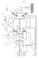
- FIG. 1is a schematic diagram of an exemplary powertrain, in accordance with the present invention.
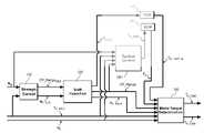
- FIG. 2is a schematic diagram of an exemplary architecture for a control system and powertrain, in accordance with the present invention
- FIG. 3is a graphical depiction, in accordance with the present invention.
- FIG. 4is a parametric flow diagram, in accordance with the present invention.
- FIGS. 1 and 2depict a system comprising an engine 14 , transmission 10 , control system, and driveline which has been constructed in accordance with an embodiment of the present invention.
- the exemplary two-mode, compound-split, electro-mechanical hybrid transmission embodying the concepts of the present inventionis depicted in FIG. 1 , and is designated generally by the numeral 10 .
- the transmission 10includes an input shaft 12 having an input speed, N I that is preferably driven by the internal combustion engine 14 .
- the engine 14has a crankshaft having characteristic speed N E which is operatively connected to the transmission input shaft 12 .
- N Echaracteristic speed
- the engine speed N E and output torque T Ecan differ from transmission input speed N I and input torque T I .
- the transmission 10utilizes three planetary-gear sets 24 , 26 and 28 , and four torque-transmitting devices, i.e., clutches C 1 70 , C 2 62 , C 3 73 , and C 4 75 .
- An electro-hydraulic control system 42preferably controlled by transmission control module 17 , is operative to control actuation and deactivation of the clutches.
- Clutches C 2 and C 4preferably comprise hydraulically-actuated rotating friction clutches.
- Clutches C 1 and C 3preferably comprise comprising hydraulically-actuated stationary devices grounded to the transmission case 68 .
- the three planetary gear sets 24 , 26 and 28each comprise simple planetary gear sets. Furthermore, the first and second planetary gear sets 24 and 26 are compounded in that the inner gear member of the first planetary gear set 24 is conjoined to an outer gear member of the second planetary gear set 26 , and connected to a first electrical machine comprising a motor/generator 56 , referred to as MG-A.
- the planetary gear sets 24 and 26are further compounded in that carrier 36 of the first planetary gear set 24 is conjoined through a shaft 60 , to the carrier 44 of the second planetary gear set 26 . As such, carriers 36 and 44 of the first and second planetary gear sets 24 and 26 , respectively, are conjoined.
- the shaft 60is also selectively connected to the carrier 52 of the third planetary gear set 28 , through clutch C 2 62 .
- the carrier 52 of the third planetary gear set 28is connected directly to the transmission output member 64 , which has an output rotational speed, N O .
- An inner gear member of the second planetary gear set 26is connected to an inner gear member of the third planetary gear set 28 through a sleeve shaft 66 that circumscribes shaft 60 , and is connected to a second electrical machine comprising a motor/generator 72 , referred to as MG-B.
- All the planetary gear sets 24 , 26 and 28 as well as MG-A 56 and MG-B 72are coaxially oriented, as about the axially disposed shaft 60 .
- MG-A and MG-Bare both of an annular configuration which permits them to circumscribe the three planetary gear sets 24 , 26 and 28 such that the planetary gear sets 24 , 26 and 28 are disposed radially inwardly of MG-A and MG-B.
- Transmission output member 64is operably connected to a vehicle driveline 90 to provide motive output torque, T O vehicle wheels.
- Each clutchis preferably hydraulically actuated, receiving pressurized hydraulic fluid from a pump, described below, via an electro-hydraulic control circuit 42 .
- the transmission 10receives input torque from the torque-generative devices, including the engine 14 and the MG-A 56 and MG-B 72 , and referred to as ‘T I ’, ‘T A ’, and ‘T B ’ respectively, as a result of energy conversion from fuel or electrical potential stored in an electrical energy storage device (ESD) 74 .
- the ESD 74typically comprises one or more batteries. Other electrical energy and electrochemical energy storage devices that have the ability to store electric power and dispense electric power may be used in place of the batteries without altering the concepts of the present invention.
- the ESD 74is preferably sized based upon factors including regenerative requirements, application issues related to typical road grade and temperature, and propulsion requirements such as emissions, power assist and electric range.
- the ESD 74is high voltage DC-coupled to TPIM 19 via DC transfer conductors 27 .
- the TPIM 19is an element of the control system described hereinafter with regard to FIG. 2 .
- the TPIM 19transmits electrical energy to and from MG-A 56 by transfer conductors 29 , and the TPIM 19 similarly transmits electrical energy to and from MG-B 72 by transfer conductors 31 .
- Electrical currentis transmitted to and from the ESD 74 in accordance with whether the ESD 74 is being charged or discharged.
- TPIM 19includes the pair of power inverters and respective motor control modules configured to receive motor control commands and control inverter states therefrom for providing motor drive or regeneration functionality.
- the respective inverterreceives current from the DC transmission lines and provides AC current to the respective electrical machine, i.e., MG-A and MG-B, over transfer conductors 29 and 31 .
- the respective inverterreceives AC current from the electrical machine over transfer conductors 29 and 31 and transmits current to the DC lines 27 .
- the net DC current provided to or from the invertersdetermines the charge or discharge operating mode of the electrical energy storage device 74 .
- MG-A 56 and MG-B 72are three-phase AC machines each having a rotor operable to rotate within a stator that is mounted on a case of the transmission.
- the inverterscomprise known complementary three-phase power electronics devices.
- FIG. 2a schematic block diagram of the control system, comprising a distributed control module architecture, is shown.
- the elements described hereinaftercomprise a subset of an overall vehicle control architecture, and are operable to provide coordinated system control of the powertrain system described herein.
- the control systemis operable to synthesize pertinent information and inputs, and execute algorithms to control various actuators to achieve control targets, including such parameters as fuel economy, emissions, performance, driveability, and protection of hardware, including batteries of ESD 74 and MG-A and MG-B 56 , 72 .
- the distributed control module architectureincludes engine control module (‘ECM’) 23 , transmission control module (‘TCM’) 17 , battery pack control module (‘BPCM’) 21 , and Transmission Power Inverter Module (‘TPIM’) 19 .
- a hybrid control module (‘HCP’) 5provides overarching control and coordination of the aforementioned control modules.
- UIUser Interface
- exemplary vehicle operator inputs to the UI 13include an accelerator pedal, a brake pedal, transmission gear selector, and, vehicle speed cruise control.
- Each of the aforementioned control modulescommunicates with other control modules, sensors, and actuators via a local area network (‘LAN’) bus 6 .
- the LAN bus 6allows for structured communication of control parameters and commands between the various control modules.
- the specific communication protocol utilizedis application-specific.
- the LAN bus and appropriate protocolsprovide for robust messaging and multi-control module interfacing between the aforementioned control modules, and other control modules providing functionality such as antilock brakes, traction control, and vehicle stability.
- the HCP 5provides overarching control of the hybrid powertrain system, serving to coordinate operation of the ECM 23 , TCM 17 , TPIM 19 , and BPCM 21 . Based upon various input signals from the UI 13 and the powertrain, including the battery pack, the HCP 5 generates various commands, including: an operator torque request (‘T O — REQ ’) output to driveline 90 , the input torque T I originating from the engine, clutch torque, (‘T CL — N ’) for the N various torque-transfer clutches C 1 , C 2 , C 3 , C 4 of the transmission 10 ; and motor input torques T A and T B for MG-A and MG-B.
- the TCM 17is operatively connected to the electro-hydraulic control circuit 42 , including monitoring various pressure sensing devices (not shown) and generating and executing control signals for various solenoids to control pressure switches and control valves contained therein.
- the ECM 23is operably connected to the engine 14 , and functions to acquire data from a variety of sensors and control a variety of actuators, respectively, of the engine 14 over a plurality of discrete lines collectively shown as aggregate line 35 .
- the ECM 23receives the engine torque command from the HCP 5 , and generates a desired axle torque, and an indication of actual input torque, T I , to the transmission, which is communicated to the HCP 5 .
- ECM 23is shown generally having bi-directional interface with engine 14 via aggregate line 35 .
- Various other parameters that may be sensed by ECM 23include engine coolant temperature, engine input speed, N E , to shaft 12 which translate to transmission input speed, N I , manifold pressure, ambient air temperature, and ambient pressure.
- Various actuators that may be controlled by the ECM 23include fuel injectors, ignition modules, and throttle control modules.
- the TCM 17is operably connected to the transmission 10 and functions to acquire data from a variety of sensors and provide command signals to the transmission. Inputs from the TCM 17 to the HCP 5 include estimated clutch torques (T CL — EST — N ) for each of the N clutches C 1 , C 2 , C 3 , and, C 4 and rotational speed, N O , of the output shaft 64 . Other actuators and sensors may be used to provide additional information from the TCM to the HCP for control purposes.
- the TCM 17monitors inputs from pressure switches and selectively actuates pressure control solenoids and shift solenoids to actuate various clutches to achieve various transmission operating modes, as described hereinbelow.
- the BPCM 21is signally connected one or more sensors operable to monitor electrical current or voltage parameters of the ESD 74 to provide information about the state of the batteries to the HCP 5 .
- Such informationincludes battery state-of-charge, battery voltage and available battery power.
- the TPIM 19includes previously referenced power inverters and motor control modules configured to receive motor control commands and control inverter states therefrom to provide motor drive or regeneration functionality.
- the TPIM 19is operable to generate the motor torque commands for MG-A 56 and MG-B 72 , i.e., T A and T B , based upon input from the HCP 5 , which is driven by operator input through UI 13 and system operating parameters.
- the motor torque commands for MG-A and MG-Bare implemented by the control system, including the TPIM 19 , to control MG-A and MG-B.
- Individual motor speed signals for MG-A and MG-Bare derived by the TPIM 19 from the motor phase information or conventional rotation sensors.
- the TPIM 19determines and communicates motor speeds to the HCP 5 .
- the electrical energy storage device 74is high-voltage DC-coupled to the TPIM 19 via DC lines 27 . Electrical current is transferable to or from the TPIM 19 in accordance with whether the ESD 74 is being charged or discharged.
- Each of the aforementioned control modulesis preferably a general-purpose digital computer generally comprising a microprocessor or central processing unit, storage mediums comprising read only memory (ROM), random access memory (RAM), electrically programmable read only memory (EPROM), high speed clock, analog to digital (A/D) and digital to analog (D/A) circuitry, and input/output circuitry and devices (I/O) and appropriate signal conditioning and buffer circuitry.
- Each control modulehas a set of control algorithms, comprising resident program instructions and calibrations stored in ROM and executed to provide the respective functions of each computer. Information transfer between the various computers is preferably accomplished using the aforementioned LAN 6 .
- Algorithms for control and state estimation in each of the control modulesare typically executed during preset loop cycles such that each algorithm is executed at least once each loop cycle.
- Algorithms stored in the non-volatile memory devicesare executed by one of the central processing units and are operable to monitor inputs from the sensing devices and execute control and diagnostic routines to control operation of the respective device, using preset calibrations.
- Loop cyclesare typically executed at regular intervals, for example each 3.125, 6.25, 12.5, 25 and 100 milliseconds during ongoing engine and vehicle operation. Alternatively, algorithms may be executed in response to occurrence of an event.
- the exemplary two-mode, compound-split, electro-mechanical transmissionoperates in several operating range states, comprising fixed gear operating modes and continuously variable operating modes with the engine on and off, described with reference to FIG. 1 , and Table 1, below.
- the various operating range states described in the tableindicate which of the specific clutches C 1 , C 2 , C 3 , and C 4 are engaged or actuated for each of the operating range states.
- MG-A and MG-Bmay each operate as electrical motors to generate motive torque, or as a generator to generate electrical energy.
- a first modei.e., Mode I
- the engine 14can be either on or off.
- a second modei.e., Mode II, is selected when clutch C 170 is released and clutch C 2 62 is simultaneously actuated to connect the shaft 60 to the carrier of the third planetary gear set 28 .
- Engine Offis defined by engine input speed, N E , being equal to zero revolutions per minute (RPM), i.e., the engine crankshaft is not rotating.
- RPMrevolutions per minute
- Other factors outside the scope of the inventionaffect when the electrical machines 56 , 72 operate as motors and generators, and are not discussed herein.
- the control systemshown primarily in FIG. 2 , is operable to provide a range of transmission output speeds at shaft 64 from relatively slow to relatively fast within each operating range state.
- the combination of two modes with a slow-to-fast output speed range in each range stateallows the transmission 10 to propel a vehicle from a stationary condition to highway speeds, and meet various other requirements as previously described. Additionally, the control system coordinates operation of the transmission 10 so as to allow synchronized shifts between the modes.
- the first and second modes of operationrefer to circumstances in which the transmission functions are controlled by one clutch, i.e., either clutch C 1 62 or C 2 70 , and by the controlled speed and torque of the electrical machines 56 and 72 , which can be referred to as a continuously variable transmission mode. Certain ranges of operation are described below in which fixed gear ratios are achieved by applying an additional clutch.
- This additional clutchmay be clutch C 3 73 or C 4 75 , as shown in the table, above.
- various transmission operating modesare plotted as a function of transmission output speed, N O , and, input speed, N I for the exemplary powertrain control system shown in FIGS. 1 and 2 .
- the Fixed Ratio operationis shown as individual lines for each of the specific gear ratios, GR 1 , GR 2 , GR 3 , and GR 4 , as described with reference to Table 1, above.
- the continuously variable Mode operationis shown as ranges of operation for each of Mode I and Mode II.
- the transmission operating range stateis switched between Fixed Ratio operation and continuously variable Mode operation by activating or deactivating specific clutches.
- the control systemis operative to determine a specific transmission operating mode based upon various criteria, using algorithms and calibrations executed by the control system, and is outside the scope of this invention. Selection of the operating range state of the transmission depends primarily on operator torque request, T O — REQ and the ability of the powertrain to meet that operator torque request.
- the low range operating stateincludes selective actuation of clutches C 2 , C 1 , and C 4 , facilitating operation in any one of continuously variable Mode I, and fixed gears GR 1 , GR 2 , and GR 3 .
- the high range operating stateincludes selective actuation of clutches C 2 , C 3 , and C 4 , facilitating operation in any one of continuously variable Mode II and fixed gears GR 3 and GR 4 . It should be recognized that ranges of continuously variable operation for Mode I and Mode II may overlap.
- the supervisory HCP control module 5 and one or more of the other control modulesdetermine the operator torque request T O — REQ , at shaft 64 .
- Selectively operated components of the transmission 10are appropriately controlled and manipulated to respond to the operator demand. For example, in the exemplary embodiment shown in FIGS. 1 and 2 , when the operator has selected a forward drive range and manipulates either the accelerator pedal or the brake pedal, the HCP 5 determines an output torque which affects how and when the vehicle accelerates or decelerates.
- Final vehicle accelerationis affected by other factors, including, e.g., road load, road grade, and vehicle mass.
- the operating modeis determined for the exemplary transmission based upon a variety of operating characteristics of the powertrain. This includes demand for an operator demand for torque, typically communicated through inputs to the UI 13 as previously described. Additionally, a demand for output torque is predicated on external conditions, including, e.g., road grade, road surface conditions, or wind load.
- the operating modemay be predicated on a powertrain torque demand caused by a control module command to operate of the electrical machines in an electrical energy generating mode or in a torque generating mode.
- the operating modecan be determined by an optimization algorithm or routine operable to determine optimum system efficiency based upon operator demand for power, battery state of charge, and energy efficiencies of the engine 14 and MG-A and MG-B 56 , 72 .
- the control systemmanages torque inputs from the engine 14 and MG-A and MG-B 56 , 72 based upon an outcome of the executed optimization routine, and system optimization occurs to optimize system efficiencies to improve fuel economy and manage battery charging. Furthermore, operation can be determined based upon a fault in a component or system.
- the HCP 5monitors the parametric states of the torque-generative devices, and determines the output of the transmission required to arrive at the desired torque output, as described hereinbelow. Under the direction of the HCP 5 , the transmission 10 operates over a range of output speeds from slow to fast in order to meet the operator demand.
- FIG. 4a preferred method of operating the exemplary powertrain system described with reference to FIGS. 1 , 2 , and 3 is now described.
- the methodcomprises the following steps in the sequence set forth.
- a preferred or desired operating range state(Op_Range DES ) is selected based primarily upon output speed, N O of shaft 64 and the operator torque request, T O — REQ .
- the selected preferred operating range statecomprises one of the transmission operating modes described with reference to Table 1 for the exemplary transmission, including fixed gear modes GR 1 , GR 2 , GR 3 , and GR 4 , and continuously variable Modes I and II, which are coupled with the engine 14 requested on or off, i.e., not rotating.
- a preferred or desired input speedis determined.
- the strategic controlis preferably executed by the HCP 5 during each 100 ms loop cycle and each 25 ms loop cycle.
- Output of the strategic controlincludes the preferred or desired operating range state (‘Op_Range DES ’) and desired input speed (‘N I — DES ’) each which are input to a shift execution control block 120 .
- the shift execution control block(Block 120 ) is executed, preferably by the HCP 5 , to selectively execute a shift and selectively perform an engine start/stop operation to achieve the preferred operating range state (‘Op_Range DES ’) described in Block 110 .
- the HCPalso determines and outputs the current actual operating range state (‘Op_Range’) of the transmission 10 , which may vary from the desired operating range due to execution times and other reasons.
- the HCPexecutes commands to start or stop rotation of the internal combustion engine 14 , depending upon the desired operating range state (‘Op_Range DES ’).
- This actionincludes the HCP communicating a plurality of engine operating commands effective to control and manage air flow, fuel, and, spark energy and timing (in a spark ignition engine) in accordance with the desired operating mode to achieve the desired input speed, N I — DES .
- An output of the shift execution block 120includes an input speed profile, N I — PROF , which preferably comprises a scalar parametric value that is a targeted input speed for the forthcoming loop cycle, based upon the engine operating commands and the operator torque request, T O — REQ .
- the shift execution control block (Block 120 )is preferably executed by the HCP 5 during each 25 ms loop cycle.
- the tactical control block(block 130 ) is executed to determine the input torque commanded from the internal combustion engine, T I — CMD , preferably by the HCP, and preferably during every 25 ms loop cycle.
- Inputs to the tactical control blockpreferably comprise the transmission output speed, N o , the input speed, N I , the operator torque request, T O — REQ , and the current operating range state (‘Op_Range’) of the transmission as determined previously in Block 120 .
- the input torque commanded or requested from the internal combustion engine, T I —CMDis communicated from the HCP to the ECM 14 for execution therein.
- Controlling the input torque from the internal combustion enginecomprises controlling operation of the engine to a preferred load operating point to achieve the input torque T I preferably without violating other operating conditions and requirements, including those related to driveability, fuel economy, and emissions.
- commanded output torques of the first and second electrical machinesT A — CMD and T B — CMD , are determined in the motor torque determination block (Block 140 ).
- the commanded output torques of the first and second electrical machinesare determined based upon input speed, N I , and the targeted input speed N I — PROF , current input torque T I , from the ECM, the operator torque request T O — REQ , and the current operating range state, and the torque transmitted by the selectively actuated torque-transfer clutches as estimated by the TCM, T CL — EST — N .
- the commanded output torques of the first and second electrical machines, T A — CMD and T B — CMDare determined based upon an allowable range of output torques of the electrical machines determinable based upon other operating characteristics including, e.g., battery or system voltage.
- the commanded output torques, T A — CMD and T B — CMDinclude considerations of motive torque generation or electrical energy generation.
- the commanded output torques of the first and second electrical machinesare determined by the HCP every 12.5 ms loop cycle and communicated from the HCP to the TPIM 27 for execution.
- the order of execution of the steps described hereinincludes determining the preferred operating range state based upon operating conditions. Actuating the clutches and engine start/stop operation takes an elapsed time in the order of 250 to 500 milliseconds. Commanding and executing a change in input torque from the engine takes an elapsed time in the order of 50-100 milliseconds. Commanding and executing a change in output torques from the electrical motors takes an elapsed time in the order of less than 50 milliseconds.
- This strategyeffects controlled rapid transitions in output torque, To, in response to the operator torque request T O — REQ , while taking into account and compensating for a range of response times of the various actuators and torque-generative devices of the powertrain.
- the strategyfurther takes into account need to provide torque damping to minimize driveline disturbances.
- additional real-time parametric feedback datais used to calculate outputs from the shift execution 120 , tactical control 130 , and motor torque determination 140 . This provides a more accurate determination of motor torque commands, leading to more efficient operation of the system and utilization of resources and energy, and smoother, lower vibration operation.
Landscapes
- Engineering & Computer Science (AREA)
- Chemical & Material Sciences (AREA)
- Combustion & Propulsion (AREA)
- Transportation (AREA)
- Mechanical Engineering (AREA)
- Automation & Control Theory (AREA)
- Electric Propulsion And Braking For Vehicles (AREA)
- Hybrid Electric Vehicles (AREA)
Abstract
Description
| TABLE 1 | ||||
| Operating | ||||
| Range State | Actuated Clutches | |||
| Mode I - Engine Off (M1_Eng_Off) | ||||
| Mode I - Engine On (M1_Eng_On) | ||||
| Fixed Ratio 1 (GR1) | ||||
| Fixed Ratio 2 (GR2) | ||||
| Mode II - Engine Off (M2_Eng_Off) | ||||
| Mode II - Engine On (M2_Eng_On) | ||||
| Fixed Ratio 3 (GR3) | ||||
| Fixed Ratio 4 (GR4) | ||||
Claims (12)
Priority Applications (3)
| Application Number | Priority Date | Filing Date | Title |
|---|---|---|---|
| US11/561,140US7691026B2 (en) | 2006-11-17 | 2006-11-17 | Control architecture for optimization and control of a hybrid powertrain system |
| DE102007053781.8ADE102007053781B4 (en) | 2006-11-17 | 2007-11-12 | Method and control system for optimizing and controlling a hybrid powertrain system |
| CN2007103051306ACN101219662B (en) | 2006-11-17 | 2007-11-19 | Control architecture for optimization and control of a hybrid powertrain system |
Applications Claiming Priority (1)
| Application Number | Priority Date | Filing Date | Title |
|---|---|---|---|
| US11/561,140US7691026B2 (en) | 2006-11-17 | 2006-11-17 | Control architecture for optimization and control of a hybrid powertrain system |
Publications (2)
| Publication Number | Publication Date |
|---|---|
| US20080120000A1 US20080120000A1 (en) | 2008-05-22 |
| US7691026B2true US7691026B2 (en) | 2010-04-06 |
Family
ID=39417937
Family Applications (1)
| Application Number | Title | Priority Date | Filing Date |
|---|---|---|---|
| US11/561,140Active2028-08-20US7691026B2 (en) | 2006-11-17 | 2006-11-17 | Control architecture for optimization and control of a hybrid powertrain system |
Country Status (3)
| Country | Link |
|---|---|
| US (1) | US7691026B2 (en) |
| CN (1) | CN101219662B (en) |
| DE (1) | DE102007053781B4 (en) |
Cited By (5)
| Publication number | Priority date | Publication date | Assignee | Title |
|---|---|---|---|---|
| US20080287255A1 (en)* | 2007-05-14 | 2008-11-20 | Snyder Bryan R | Control architecture and method to evaluate engine off operation of a hybrid powertrain system operating in a continuously variable mode |
| US20100041512A1 (en)* | 2008-08-15 | 2010-02-18 | Silveri Andrew J | Preventing Gear Shift Cycling of a Hybrid Electric Vehicle |
| US20100304925A1 (en)* | 2007-10-24 | 2010-12-02 | Zf Friedrichshafen Ag | Motor vehicle control system |
| US20100318251A1 (en)* | 2007-10-24 | 2010-12-16 | Zf Friedrichshafen Ag | Motor vehicle control system |
| US20110166726A1 (en)* | 2007-10-24 | 2011-07-07 | Zf Friedrichshafen Ag | Motor vehicle control system |
Families Citing this family (155)
| Publication number | Priority date | Publication date | Assignee | Title |
|---|---|---|---|---|
| US8010263B2 (en)* | 2006-03-22 | 2011-08-30 | GM Global Technology Operations LLC | Method and apparatus for multivariate active driveline damping |
| US8091667B2 (en) | 2006-06-07 | 2012-01-10 | GM Global Technology Operations LLC | Method for operating a hybrid electric powertrain based on predictive effects upon an electrical energy storage device |
| US7987934B2 (en) | 2007-03-29 | 2011-08-02 | GM Global Technology Operations LLC | Method for controlling engine speed in a hybrid electric vehicle |
| US7996145B2 (en) | 2007-05-03 | 2011-08-09 | GM Global Technology Operations LLC | Method and apparatus to control engine restart for a hybrid powertrain system |
| US7999496B2 (en)* | 2007-05-03 | 2011-08-16 | GM Global Technology Operations LLC | Method and apparatus to determine rotational position of an electrical machine |
| US8390240B2 (en)* | 2007-08-06 | 2013-03-05 | GM Global Technology Operations LLC | Absolute position sensor for field-oriented control of an induction motor |
| US8265813B2 (en)* | 2007-09-11 | 2012-09-11 | GM Global Technology Operations LLC | Method and control architecture for optimization of engine fuel-cutoff selection and engine input torque for a hybrid powertrain system |
| US7988591B2 (en)* | 2007-09-11 | 2011-08-02 | GM Global Technology Operations LLC | Control architecture and method for one-dimensional optimization of input torque and motor torque in fixed gear for a hybrid powertrain system |
| US7983823B2 (en) | 2007-09-11 | 2011-07-19 | GM Global Technology Operations LLC | Method and control architecture for selection of optimal engine input torque for a powertrain system |
| US8027771B2 (en)* | 2007-09-13 | 2011-09-27 | GM Global Technology Operations LLC | Method and apparatus to monitor an output speed sensor during operation of an electro-mechanical transmission |
| US7867135B2 (en) | 2007-09-26 | 2011-01-11 | GM Global Technology Operations LLC | Electro-mechanical transmission control system |
| JP2009083594A (en)* | 2007-09-28 | 2009-04-23 | Toyota Motor Corp | Control device for vehicle power transmission device |
| US8062170B2 (en)* | 2007-09-28 | 2011-11-22 | GM Global Technology Operations LLC | Thermal protection of an electric drive system |
| US8234048B2 (en)* | 2007-10-19 | 2012-07-31 | GM Global Technology Operations LLC | Method and system for inhibiting operation in a commanded operating range state for a transmission of a powertrain system |
| US9140337B2 (en)* | 2007-10-23 | 2015-09-22 | GM Global Technology Operations LLC | Method for model based clutch control and torque estimation |
| US8060267B2 (en)* | 2007-10-23 | 2011-11-15 | GM Global Technology Operations LLC | Method for controlling power flow within a powertrain system |
| US8187145B2 (en) | 2007-10-25 | 2012-05-29 | GM Global Technology Operations LLC | Method and apparatus for clutch torque control in mode and fixed gear for a hybrid powertrain system |
| US8265821B2 (en)* | 2007-10-25 | 2012-09-11 | GM Global Technology Operations LLC | Method for determining a voltage level across an electric circuit of a powertrain |
| US8296027B2 (en) | 2007-10-25 | 2012-10-23 | GM Global Technology Operations LLC | Method and apparatus to control off-going clutch torque during torque phase for a hybrid powertrain system |
| US8335623B2 (en)* | 2007-10-25 | 2012-12-18 | GM Global Technology Operations LLC | Method and apparatus for remediation of and recovery from a clutch slip event in a hybrid powertrain system |
| US8118122B2 (en)* | 2007-10-25 | 2012-02-21 | GM Global Technology Operations LLC | Method and system for monitoring signal integrity in a distributed controls system |
| US8204702B2 (en)* | 2007-10-26 | 2012-06-19 | GM Global Technology Operations LLC | Method for estimating battery life in a hybrid powertrain |
| US8303463B2 (en)* | 2007-10-26 | 2012-11-06 | GM Global Technology Operations LLC | Method and apparatus to control clutch fill pressure in an electro-mechanical transmission |
| US8548703B2 (en) | 2007-10-26 | 2013-10-01 | GM Global Technology Operations LLC | Method and apparatus to determine clutch slippage in an electro-mechanical transmission |
| US8560191B2 (en) | 2007-10-26 | 2013-10-15 | GM Global Technology Operations LLC | Method and apparatus to control clutch pressures in an electro-mechanical transmission |
| US9097337B2 (en) | 2007-10-26 | 2015-08-04 | GM Global Technology Operations LLC | Method and apparatus to control hydraulic line pressure in an electro-mechanical transmission |
| US8406945B2 (en)* | 2007-10-26 | 2013-03-26 | GM Global Technology Operations LLC | Method and apparatus to control logic valves for hydraulic flow control in an electro-mechanical transmission |
| US8167773B2 (en) | 2007-10-26 | 2012-05-01 | GM Global Technology Operations LLC | Method and apparatus to control motor cooling in an electro-mechanical transmission |
| US7985154B2 (en) | 2007-10-26 | 2011-07-26 | GM Global Technology Operations LLC | Method and apparatus to control hydraulic pressure for component lubrication in an electro-mechanical transmission |
| US8244426B2 (en)* | 2007-10-27 | 2012-08-14 | GM Global Technology Operations LLC | Method and apparatus for monitoring processor integrity in a distributed control module system for a powertrain system |
| US8099219B2 (en) | 2007-10-27 | 2012-01-17 | GM Global Technology Operations LLC | Method and apparatus for securing an operating range state mechanical transmission |
| US8062174B2 (en)* | 2007-10-27 | 2011-11-22 | GM Global Technology Operations LLC | Method and apparatus to control clutch stroke volume in an electro-mechanical transmission |
| US8428816B2 (en)* | 2007-10-27 | 2013-04-23 | GM Global Technology Operations LLC | Method and apparatus for monitoring software and signal integrity in a distributed control module system for a powertrain system |
| US8290681B2 (en)* | 2007-10-29 | 2012-10-16 | GM Global Technology Operations LLC | Method and apparatus to produce a smooth input speed profile in mode for a hybrid powertrain system |
| US8170762B2 (en) | 2007-10-29 | 2012-05-01 | GM Global Technology Operations LLC | Method and apparatus to control operation of a hydraulic pump for an electro-mechanical transmission |
| US8209098B2 (en)* | 2007-10-29 | 2012-06-26 | GM Global Technology Operations LLC | Method and apparatus for monitoring a transmission range selector in a hybrid powertrain transmission |
| US8282526B2 (en)* | 2007-10-29 | 2012-10-09 | GM Global Technology Operations LLC | Method and apparatus to create a pseudo torque phase during oncoming clutch engagement to prevent clutch slip for a hybrid powertrain system |
| US8095254B2 (en)* | 2007-10-29 | 2012-01-10 | GM Global Technology Operations LLC | Method for determining a power constraint for controlling a powertrain system |
| US8112194B2 (en)* | 2007-10-29 | 2012-02-07 | GM Global Technology Operations LLC | Method and apparatus for monitoring regenerative operation in a hybrid powertrain system |
| US8489293B2 (en)* | 2007-10-29 | 2013-07-16 | GM Global Technology Operations LLC | Method and apparatus to control input speed profile during inertia speed phase for a hybrid powertrain system |
| US8078371B2 (en) | 2007-10-31 | 2011-12-13 | GM Global Technology Operations LLC | Method and apparatus to monitor output of an electro-mechanical transmission |
| US8073602B2 (en)* | 2007-11-01 | 2011-12-06 | GM Global Technology Operations LLC | System constraints method of controlling operation of an electro-mechanical transmission with an additional constraint range |
| US7977896B2 (en) | 2007-11-01 | 2011-07-12 | GM Global Technology Operations LLC | Method of determining torque limit with motor torque and battery power constraints |
| US8556011B2 (en)* | 2007-11-01 | 2013-10-15 | GM Global Technology Operations LLC | Prediction strategy for thermal management and protection of power electronic hardware |
| US8035324B2 (en) | 2007-11-01 | 2011-10-11 | GM Global Technology Operations LLC | Method for determining an achievable torque operating region for a transmission |
| US8145375B2 (en)* | 2007-11-01 | 2012-03-27 | GM Global Technology Operations LLC | System constraints method of determining minimum and maximum torque limits for an electro-mechanical powertrain system |
| US8133151B2 (en)* | 2007-11-02 | 2012-03-13 | GM Global Technology Operations LLC | System constraints method of controlling operation of an electro-mechanical transmission with an additional constraint |
| US8287426B2 (en)* | 2007-11-02 | 2012-10-16 | GM Global Technology Operations LLC | Method for controlling voltage within a powertrain system |
| US8200403B2 (en) | 2007-11-02 | 2012-06-12 | GM Global Technology Operations LLC | Method for controlling input torque provided to a transmission |
| US8825320B2 (en)* | 2007-11-02 | 2014-09-02 | GM Global Technology Operations LLC | Method and apparatus for developing a deceleration-based synchronous shift schedule |
| US8131437B2 (en)* | 2007-11-02 | 2012-03-06 | GM Global Technology Operations LLC | Method for operating a powertrain system to transition between engine states |
| US8585540B2 (en) | 2007-11-02 | 2013-11-19 | GM Global Technology Operations LLC | Control system for engine torque management for a hybrid powertrain system |
| US8847426B2 (en) | 2007-11-02 | 2014-09-30 | GM Global Technology Operations LLC | Method for managing electric power in a powertrain system |
| US8121767B2 (en)* | 2007-11-02 | 2012-02-21 | GM Global Technology Operations LLC | Predicted and immediate output torque control architecture for a hybrid powertrain system |
| US8121765B2 (en)* | 2007-11-02 | 2012-02-21 | GM Global Technology Operations LLC | System constraints method of controlling operation of an electro-mechanical transmission with two external input torque ranges |
| US8224539B2 (en) | 2007-11-02 | 2012-07-17 | GM Global Technology Operations LLC | Method for altitude-compensated transmission shift scheduling |
| US8002667B2 (en)* | 2007-11-03 | 2011-08-23 | GM Global Technology Operations LLC | Method for determining input speed acceleration limits in a hybrid transmission |
| US8155814B2 (en) | 2007-11-03 | 2012-04-10 | GM Global Technology Operations LLC | Method of operating a vehicle utilizing regenerative braking |
| US8204664B2 (en) | 2007-11-03 | 2012-06-19 | GM Global Technology Operations LLC | Method for controlling regenerative braking in a vehicle |
| US8260511B2 (en)* | 2007-11-03 | 2012-09-04 | GM Global Technology Operations LLC | Method for stabilization of mode and fixed gear for a hybrid powertrain system |
| US8135526B2 (en)* | 2007-11-03 | 2012-03-13 | GM Global Technology Operations LLC | Method for controlling regenerative braking and friction braking |
| US8406970B2 (en) | 2007-11-03 | 2013-03-26 | GM Global Technology Operations LLC | Method for stabilization of optimal input speed in mode for a hybrid powertrain system |
| US8296021B2 (en) | 2007-11-03 | 2012-10-23 | GM Global Technology Operations LLC | Method for determining constraints on input torque in a hybrid transmission |
| US8068966B2 (en) | 2007-11-03 | 2011-11-29 | GM Global Technology Operations LLC | Method for monitoring an auxiliary pump for a hybrid powertrain |
| US8224514B2 (en)* | 2007-11-03 | 2012-07-17 | GM Global Technology Operations LLC | Creation and depletion of short term power capability in a hybrid electric vehicle |
| US8285431B2 (en) | 2007-11-03 | 2012-10-09 | GM Global Technology Operations LLC | Optimal selection of hybrid range state and/or input speed with a blended braking system in a hybrid electric vehicle |
| US8010247B2 (en) | 2007-11-03 | 2011-08-30 | GM Global Technology Operations LLC | Method for operating an engine in a hybrid powertrain system |
| US8868252B2 (en)* | 2007-11-03 | 2014-10-21 | GM Global Technology Operations LLC | Control architecture and method for two-dimensional optimization of input speed and input power including search windowing |
| US8112206B2 (en) | 2007-11-04 | 2012-02-07 | GM Global Technology Operations LLC | Method for controlling a powertrain system based upon energy storage device temperature |
| US8145397B2 (en)* | 2007-11-04 | 2012-03-27 | GM Global Technology Operations LLC | Optimal selection of blended braking capacity for a hybrid electric vehicle |
| US8126624B2 (en) | 2007-11-04 | 2012-02-28 | GM Global Technology Operations LLC | Method for selection of optimal mode and gear and input speed for preselect or tap up/down operation |
| US8204656B2 (en) | 2007-11-04 | 2012-06-19 | GM Global Technology Operations LLC | Control architecture for output torque shaping and motor torque determination for a hybrid powertrain system |
| US8092339B2 (en)* | 2007-11-04 | 2012-01-10 | GM Global Technology Operations LLC | Method and apparatus to prioritize input acceleration and clutch synchronization performance in neutral for a hybrid powertrain system |
| US8818660B2 (en)* | 2007-11-04 | 2014-08-26 | GM Global Technology Operations LLC | Method for managing lash in a driveline |
| US8214120B2 (en)* | 2007-11-04 | 2012-07-03 | GM Global Technology Operations LLC | Method to manage a high voltage system in a hybrid powertrain system |
| US8079933B2 (en) | 2007-11-04 | 2011-12-20 | GM Global Technology Operations LLC | Method and apparatus to control engine torque to peak main pressure for a hybrid powertrain system |
| US8504259B2 (en) | 2007-11-04 | 2013-08-06 | GM Global Technology Operations LLC | Method for determining inertia effects for a hybrid powertrain system |
| US8594867B2 (en)* | 2007-11-04 | 2013-11-26 | GM Global Technology Operations LLC | System architecture for a blended braking system in a hybrid powertrain system |
| US8135532B2 (en)* | 2007-11-04 | 2012-03-13 | GM Global Technology Operations LLC | Method for controlling output power of an energy storage device in a powertrain system |
| US8897975B2 (en)* | 2007-11-04 | 2014-11-25 | GM Global Technology Operations LLC | Method for controlling a powertrain system based on penalty costs |
| US8200383B2 (en) | 2007-11-04 | 2012-06-12 | GM Global Technology Operations LLC | Method for controlling a powertrain system based upon torque machine temperature |
| US8494732B2 (en)* | 2007-11-04 | 2013-07-23 | GM Global Technology Operations LLC | Method for determining a preferred engine operation in a hybrid powertrain system during blended braking |
| US8098041B2 (en) | 2007-11-04 | 2012-01-17 | GM Global Technology Operations LLC | Method of charging a powertrain |
| US8095282B2 (en) | 2007-11-04 | 2012-01-10 | GM Global Technology Operations LLC | Method and apparatus for soft costing input speed and output speed in mode and fixed gear as function of system temperatures for cold and hot operation for a hybrid powertrain system |
| US8214114B2 (en) | 2007-11-04 | 2012-07-03 | GM Global Technology Operations LLC | Control of engine torque for traction and stability control events for a hybrid powertrain system |
| US8067908B2 (en)* | 2007-11-04 | 2011-11-29 | GM Global Technology Operations LLC | Method for electric power boosting in a powertrain system |
| US8374758B2 (en) | 2007-11-04 | 2013-02-12 | GM Global Technology Operations LLC | Method for developing a trip cost structure to understand input speed trip for a hybrid powertrain system |
| US8000866B2 (en) | 2007-11-04 | 2011-08-16 | GM Global Technology Operations LLC | Engine control system for torque management in a hybrid powertrain system |
| US8112192B2 (en)* | 2007-11-04 | 2012-02-07 | GM Global Technology Operations LLC | Method for managing electric power within a powertrain system |
| US8396634B2 (en) | 2007-11-04 | 2013-03-12 | GM Global Technology Operations LLC | Method and apparatus for maximum and minimum output torque performance by selection of hybrid range state and input speed for a hybrid powertrain system |
| US8121766B2 (en)* | 2007-11-04 | 2012-02-21 | GM Global Technology Operations LLC | Method for operating an internal combustion engine to transmit power to a driveline |
| US8002665B2 (en)* | 2007-11-04 | 2011-08-23 | GM Global Technology Operations LLC | Method for controlling power actuators in a hybrid powertrain system |
| US8630776B2 (en)* | 2007-11-04 | 2014-01-14 | GM Global Technology Operations LLC | Method for controlling an engine of a hybrid powertrain in a fuel enrichment mode |
| US8346449B2 (en) | 2007-11-04 | 2013-01-01 | GM Global Technology Operations LLC | Method and apparatus to provide necessary output torque reserve by selection of hybrid range state and input speed for a hybrid powertrain system |
| US8221285B2 (en)* | 2007-11-04 | 2012-07-17 | GM Global Technology Operations LLC | Method and apparatus to offload offgoing clutch torque with asynchronous oncoming clutch torque, engine and motor torque for a hybrid powertrain system |
| US8138703B2 (en)* | 2007-11-04 | 2012-03-20 | GM Global Technology Operations LLC | Method and apparatus for constraining output torque in a hybrid powertrain system |
| US8214093B2 (en)* | 2007-11-04 | 2012-07-03 | GM Global Technology Operations LLC | Method and apparatus to prioritize transmission output torque and input acceleration for a hybrid powertrain system |
| US9008926B2 (en) | 2007-11-04 | 2015-04-14 | GM Global Technology Operations LLC | Control of engine torque during upshift and downshift torque phase for a hybrid powertrain system |
| US7988594B2 (en) | 2007-11-04 | 2011-08-02 | GM Global Technology Operations LLC | Method for load-based stabilization of mode and fixed gear operation of a hybrid powertrain system |
| US8118903B2 (en) | 2007-11-04 | 2012-02-21 | GM Global Technology Operations LLC | Method for preferential selection of modes and gear with inertia effects for a hybrid powertrain system |
| US8414449B2 (en)* | 2007-11-04 | 2013-04-09 | GM Global Technology Operations LLC | Method and apparatus to perform asynchronous shifts with oncoming slipping clutch torque for a hybrid powertrain system |
| US8248023B2 (en)* | 2007-11-04 | 2012-08-21 | GM Global Technology Operations LLC | Method of externally charging a powertrain |
| US8155815B2 (en)* | 2007-11-05 | 2012-04-10 | Gm Global Technology Operation Llc | Method and apparatus for securing output torque in a distributed control module system for a powertrain system |
| US8448731B2 (en) | 2007-11-05 | 2013-05-28 | GM Global Technology Operations LLC | Method and apparatus for determination of fast actuating engine torque for a hybrid powertrain system |
| US8219303B2 (en) | 2007-11-05 | 2012-07-10 | GM Global Technology Operations LLC | Method for operating an internal combustion engine for a hybrid powertrain system |
| US8285462B2 (en) | 2007-11-05 | 2012-10-09 | GM Global Technology Operations LLC | Method and apparatus to determine a preferred output torque in mode and fixed gear operation with clutch torque constraints for a hybrid powertrain system |
| US8229633B2 (en) | 2007-11-05 | 2012-07-24 | GM Global Technology Operations LLC | Method for operating a powertrain system to control engine stabilization |
| US8249766B2 (en)* | 2007-11-05 | 2012-08-21 | GM Global Technology Operations LLC | Method of determining output torque limits of a hybrid transmission operating in a fixed gear operating range state |
| US8321100B2 (en)* | 2007-11-05 | 2012-11-27 | GM Global Technology Operations LLC | Method and apparatus for dynamic output torque limiting for a hybrid powertrain system |
| US8099204B2 (en) | 2007-11-05 | 2012-01-17 | GM Global Technology Operatons LLC | Method for controlling electric boost in a hybrid powertrain |
| US8121768B2 (en)* | 2007-11-05 | 2012-02-21 | GM Global Technology Operations LLC | Method for controlling a hybrid powertrain system based upon hydraulic pressure and clutch reactive torque capacity |
| US8165777B2 (en) | 2007-11-05 | 2012-04-24 | GM Global Technology Operations LLC | Method to compensate for transmission spin loss for a hybrid powertrain system |
| US8285432B2 (en)* | 2007-11-05 | 2012-10-09 | GM Global Technology Operations LLC | Method and apparatus for developing a control architecture for coordinating shift execution and engine torque control |
| US8070647B2 (en) | 2007-11-05 | 2011-12-06 | GM Global Technology Operations LLC | Method and apparatus for adapting engine operation in a hybrid powertrain system for active driveline damping |
| US8135519B2 (en)* | 2007-11-05 | 2012-03-13 | GM Global Technology Operations LLC | Method and apparatus to determine a preferred output torque for operating a hybrid transmission in a fixed gear operating range state |
| US8073601B2 (en)* | 2007-11-05 | 2011-12-06 | GM Global Technology Operations LLC | Method for preferential selection of mode and gear and input speed based on multiple engine state fueling costs for a hybrid powertrain system |
| US8112207B2 (en) | 2007-11-05 | 2012-02-07 | GM Global Technology Operations LLC | Method and apparatus to determine a preferred output torque for operating a hybrid transmission in a continuously variable mode |
| US8160761B2 (en)* | 2007-11-05 | 2012-04-17 | GM Global Technology Operations LLC | Method for predicting an operator torque request of a hybrid powertrain system |
| US8281885B2 (en) | 2007-11-06 | 2012-10-09 | GM Global Technology Operations LLC | Method and apparatus to monitor rotational speeds in an electro-mechanical transmission |
| US8179127B2 (en)* | 2007-11-06 | 2012-05-15 | GM Global Technology Operations LLC | Method and apparatus to monitor position of a rotatable shaft |
| US8195349B2 (en)* | 2007-11-07 | 2012-06-05 | GM Global Technology Operations LLC | Method for predicting a speed output of a hybrid powertrain system |
| US8277363B2 (en) | 2007-11-07 | 2012-10-02 | GM Global Technology Operations LLC | Method and apparatus to control temperature of an exhaust aftertreatment system for a hybrid powertrain |
| US8005632B2 (en)* | 2007-11-07 | 2011-08-23 | GM Global Technology Operations LLC | Method and apparatus for detecting faults in a current sensing device |
| US8073610B2 (en) | 2007-11-07 | 2011-12-06 | GM Global Technology Operations LLC | Method and apparatus to control warm-up of an exhaust aftertreatment system for a hybrid powertrain |
| US8267837B2 (en) | 2007-11-07 | 2012-09-18 | GM Global Technology Operations LLC | Method and apparatus to control engine temperature for a hybrid powertrain |
| US8209097B2 (en)* | 2007-11-07 | 2012-06-26 | GM Global Technology Operations LLC | Method and control architecture to determine motor torque split in fixed gear operation for a hybrid powertrain system |
| US8224544B2 (en)* | 2007-11-07 | 2012-07-17 | GM Global Technology Operations LLC | Method and apparatus to control launch of a vehicle having an electro-mechanical transmission |
| US8271173B2 (en) | 2007-11-07 | 2012-09-18 | GM Global Technology Operations LLC | Method and apparatus for controlling a hybrid powertrain system |
| US8433486B2 (en)* | 2007-11-07 | 2013-04-30 | GM Global Technology Operations LLC | Method and apparatus to determine a preferred operating point for an engine of a powertrain system using an iterative search |
| HUP0800048A2 (en)* | 2008-01-25 | 2009-08-28 | Istvan Dr Janosi | Frying device for making fried cake specially for household |
| US8827865B2 (en) | 2011-08-31 | 2014-09-09 | GM Global Technology Operations LLC | Control system for a hybrid powertrain system |
| US8801567B2 (en) | 2012-02-17 | 2014-08-12 | GM Global Technology Operations LLC | Method and apparatus for executing an asynchronous clutch-to-clutch shift in a hybrid transmission |
| US9026327B2 (en)* | 2012-05-02 | 2015-05-05 | GM Global Technology Operations LLC | Method and apparatus for executing a shift path to a target powertrain state |
| US20140228166A1 (en)* | 2013-02-12 | 2014-08-14 | GM Global Technology Operations LLC | Method and apparatus for controlling motor torques in a multi-mode powertrain system |
| WO2015113424A1 (en) | 2014-01-30 | 2015-08-06 | 比亚迪股份有限公司 | Vehicle and power transmission system thereof |
| CN104276031B (en) | 2014-01-30 | 2016-01-13 | 比亚迪股份有限公司 | Vehicle and drive control method thereof |
| US9568081B2 (en) | 2014-01-30 | 2017-02-14 | Byd Company Limited | Power transmission system for vehicle and vehicle comprising the same |
| CN104279311B (en) | 2014-01-30 | 2015-11-25 | 比亚迪股份有限公司 | The controlling method of synchronizer and vehicle in vehicle |
| US9568080B2 (en) | 2014-01-30 | 2017-02-14 | Byd Company Limited | Power transmission system for vehicle and vehicle comprising the same |
| WO2015113412A1 (en) | 2014-01-30 | 2015-08-06 | Byd Company Limited | Power transmission system for vehicle and vehicle comprising the same |
| CN104276163B (en) | 2014-01-30 | 2015-11-25 | 比亚迪股份有限公司 | The control method of engine in vehicle unit and vehicle |
| WO2015113415A1 (en) | 2014-01-30 | 2015-08-06 | Byd Company Limited | Power transmission system for vehicle and vehicle comprising the same |
| WO2015113414A1 (en) | 2014-01-30 | 2015-08-06 | Byd Company Limited | Power transmission system for vehicle and vehicle comprising the same |
| US9409561B2 (en)* | 2014-04-21 | 2016-08-09 | Ford Global Technologies, Llc | Coordinated engine start in hybrid vehicle |
| CN104102200B (en)* | 2014-07-07 | 2016-10-26 | 安徽农业大学 | A kind of transfer gear design system based on structure with control integrated optimization |
| US9874266B2 (en) | 2014-09-10 | 2018-01-23 | Byd Company Limited | Power transmission system and vehicle comprising the same |
| WO2016037468A1 (en) | 2014-09-10 | 2016-03-17 | Byd Company Limited | Power transmission system and vehicle comprising the same |
| EP2995489B1 (en) | 2014-09-10 | 2020-01-22 | BYD Company Limited | Transmission unit, power transmission system and vehicle comprising the same |
| CN104608760B (en) | 2014-10-20 | 2016-05-25 | 比亚迪股份有限公司 | Hybrid vehicle and shift control method thereof, power drive system |
| CN106143479B (en)* | 2015-03-25 | 2019-04-19 | 比亚迪股份有限公司 | Hybrid electric vehicle and its drive control method and device |
| CN106143475B (en)* | 2015-03-25 | 2019-01-11 | 比亚迪股份有限公司 | Hybrid vehicle and its drive control method and apparatus |
| CN106143478B (en)* | 2015-03-25 | 2019-04-19 | 比亚迪股份有限公司 | Drive control method and device for hybrid electric vehicle |
| CN106143477B (en)* | 2015-03-25 | 2019-03-29 | 比亚迪股份有限公司 | Hybrid vehicle and its drive control method and apparatus |
| US10126810B2 (en)* | 2015-09-29 | 2018-11-13 | Emerson Process Management Power & Water Solutions, Inc. | Method for controlling power generation unit to desired output as specified by load demand signal by using modified control signal |
| US20170305405A1 (en)* | 2016-04-22 | 2017-10-26 | GM Global Technology Operations LLC | Method and apparatus for transmission gear selection in a parallel-hybrid powertrain system |
Citations (1)
| Publication number | Priority date | Publication date | Assignee | Title |
|---|---|---|---|---|
| US20060289212A1 (en)* | 2005-06-27 | 2006-12-28 | Nissan Motor Co., Ltd. | Hybrid vehicle control operation |
Family Cites Families (5)
| Publication number | Priority date | Publication date | Assignee | Title |
|---|---|---|---|---|
| DE19909424A1 (en)* | 1999-02-23 | 2000-08-24 | Peter Tenberge | Hybrid gearing for vehicle |
| US6991053B2 (en)* | 2003-02-27 | 2006-01-31 | Ford Global Technologies, Llc | Closed-loop power control for hybrid electric vehicles |
| JP3823949B2 (en)* | 2003-06-23 | 2006-09-20 | 日産自動車株式会社 | Hybrid vehicle mode transition control device |
| JP3991975B2 (en)* | 2003-11-12 | 2007-10-17 | 日産自動車株式会社 | Shift control device for hybrid transmission |
| US6953409B2 (en)* | 2003-12-19 | 2005-10-11 | General Motors Corporation | Two-mode, compound-split, hybrid electro-mechanical transmission having four fixed ratios |
- 2006
- 2006-11-17USUS11/561,140patent/US7691026B2/enactiveActive
- 2007
- 2007-11-12DEDE102007053781.8Apatent/DE102007053781B4/enactiveActive
- 2007-11-19CNCN2007103051306Apatent/CN101219662B/enactiveActive
Patent Citations (1)
| Publication number | Priority date | Publication date | Assignee | Title |
|---|---|---|---|---|
| US20060289212A1 (en)* | 2005-06-27 | 2006-12-28 | Nissan Motor Co., Ltd. | Hybrid vehicle control operation |
Cited By (10)
| Publication number | Priority date | Publication date | Assignee | Title |
|---|---|---|---|---|
| US20080287255A1 (en)* | 2007-05-14 | 2008-11-20 | Snyder Bryan R | Control architecture and method to evaluate engine off operation of a hybrid powertrain system operating in a continuously variable mode |
| US7991519B2 (en)* | 2007-05-14 | 2011-08-02 | GM Global Technology Operations LLC | Control architecture and method to evaluate engine off operation of a hybrid powertrain system operating in a continuously variable mode |
| US20100304925A1 (en)* | 2007-10-24 | 2010-12-02 | Zf Friedrichshafen Ag | Motor vehicle control system |
| US20100318251A1 (en)* | 2007-10-24 | 2010-12-16 | Zf Friedrichshafen Ag | Motor vehicle control system |
| US20110166726A1 (en)* | 2007-10-24 | 2011-07-07 | Zf Friedrichshafen Ag | Motor vehicle control system |
| US8290655B2 (en)* | 2007-10-24 | 2012-10-16 | Zf Friedrichshafen Ag | Hybrid drive motor vehicle control system comprising distributed functional components for controlling hybrid drive operating status |
| US8386142B2 (en)* | 2007-10-24 | 2013-02-26 | Zf Friedrichshafen Ag | Hybrid drive motor vehicle control system comprising distributed functional components for controlling hybrid drive operating status |
| US8396619B2 (en)* | 2007-10-24 | 2013-03-12 | Zf Friedrichshafen Ag | Hybrid drive motor vehicle control system comprising distributed functional components for controlling hybrid drive operating status |
| US20100041512A1 (en)* | 2008-08-15 | 2010-02-18 | Silveri Andrew J | Preventing Gear Shift Cycling of a Hybrid Electric Vehicle |
| US8257222B2 (en)* | 2008-08-15 | 2012-09-04 | Ford Global Technologies, Llc | Preventing gear shift cycling of a hybrid electric vehicle |
Also Published As
| Publication number | Publication date |
|---|---|
| US20080120000A1 (en) | 2008-05-22 |
| CN101219662A (en) | 2008-07-16 |
| DE102007053781B4 (en) | 2021-03-04 |
| DE102007053781A1 (en) | 2008-06-26 |
| CN101219662B (en) | 2011-07-06 |
Similar Documents
| Publication | Publication Date | Title |
|---|---|---|
| US7691026B2 (en) | Control architecture for optimization and control of a hybrid powertrain system | |
| US7568994B2 (en) | Control architecture for selection of optimal mode or gear and input speed for a hybrid powertrain system | |
| US7853386B2 (en) | Control architecture and method for two-dimensional optimization of input speed and input torque in mode for a hybrid powertrain system | |
| US7991519B2 (en) | Control architecture and method to evaluate engine off operation of a hybrid powertrain system operating in a continuously variable mode | |
| US7641582B2 (en) | Control architecture and method for two-dimensional optimization of input torque and motor torque in fixed gear for a hybrid powertrain system | |
| US7568990B2 (en) | Method and apparatus to control operation of a hydraulic control circuit for an electro-mechanical transmission | |
| US7497803B2 (en) | Method and apparatus to control an electro-hydraulic transmission during shifting event | |
| US7706949B2 (en) | Method and apparatus to control an electro-mechanical transmission during shifting event | |
| US8121767B2 (en) | Predicted and immediate output torque control architecture for a hybrid powertrain system | |
| US8594867B2 (en) | System architecture for a blended braking system in a hybrid powertrain system | |
| US7555374B2 (en) | Method for monitoring a motor speed sensor | |
| US8121768B2 (en) | Method for controlling a hybrid powertrain system based upon hydraulic pressure and clutch reactive torque capacity | |
| US8060267B2 (en) | Method for controlling power flow within a powertrain system | |
| US7988591B2 (en) | Control architecture and method for one-dimensional optimization of input torque and motor torque in fixed gear for a hybrid powertrain system | |
| US8214114B2 (en) | Control of engine torque for traction and stability control events for a hybrid powertrain system | |
| US7601092B2 (en) | Vehicle propulsion system | |
| US8585540B2 (en) | Control system for engine torque management for a hybrid powertrain system | |
| US8321100B2 (en) | Method and apparatus for dynamic output torque limiting for a hybrid powertrain system | |
| US7983823B2 (en) | Method and control architecture for selection of optimal engine input torque for a powertrain system | |
| US7670254B2 (en) | Method and apparatus to monitor devices of a hydraulic circuit of an electro-mechanical transmission | |
| US8224544B2 (en) | Method and apparatus to control launch of a vehicle having an electro-mechanical transmission | |
| US8847426B2 (en) | Method for managing electric power in a powertrain system | |
| US7908063B2 (en) | Synchronous shift execution for hybrid transmission | |
| EP2058203B1 (en) | Method and apparatus for dynamic output torque limiting for a hybrid powertrain system |
Legal Events
| Date | Code | Title | Description |
|---|---|---|---|
| AS | Assignment | Owner name:GM GLOBAL TECHNOLOGY OPERATIONS, INC,MICHIGAN Free format text:ASSIGNMENT OF ASSIGNORS INTEREST;ASSIGNORS:HEAP, ANTHONY H.;CAWTHORNE, WILLIAM R.;REEL/FRAME:018704/0336 Effective date:20061011 Owner name:GM GLOBAL TECHNOLOGY OPERATIONS, INC, MICHIGAN Free format text:ASSIGNMENT OF ASSIGNORS INTEREST;ASSIGNORS:HEAP, ANTHONY H.;CAWTHORNE, WILLIAM R.;REEL/FRAME:018704/0336 Effective date:20061011 | |
| AS | Assignment | Owner name:UNITED STATES DEPARTMENT OF THE TREASURY,DISTRICT Free format text:SECURITY AGREEMENT;ASSIGNOR:GM GLOBAL TECHNOLOGY OPERATIONS, INC.;REEL/FRAME:022201/0405 Effective date:20081231 Owner name:UNITED STATES DEPARTMENT OF THE TREASURY, DISTRICT Free format text:SECURITY AGREEMENT;ASSIGNOR:GM GLOBAL TECHNOLOGY OPERATIONS, INC.;REEL/FRAME:022201/0405 Effective date:20081231 | |
| AS | Assignment | Owner name:CITICORP USA, INC. AS AGENT FOR HEDGE PRIORITY SEC Free format text:SECURITY AGREEMENT;ASSIGNOR:GM GLOBAL TECHNOLOGY OPERATIONS, INC.;REEL/FRAME:022553/0540 Effective date:20090409 Owner name:CITICORP USA, INC. AS AGENT FOR BANK PRIORITY SECU Free format text:SECURITY AGREEMENT;ASSIGNOR:GM GLOBAL TECHNOLOGY OPERATIONS, INC.;REEL/FRAME:022553/0540 Effective date:20090409 | |
| AS | Assignment | Owner name:GM GLOBAL TECHNOLOGY OPERATIONS, INC.,MICHIGAN Free format text:RELEASE BY SECURED PARTY;ASSIGNOR:UNITED STATES DEPARTMENT OF THE TREASURY;REEL/FRAME:023124/0563 Effective date:20090709 Owner name:GM GLOBAL TECHNOLOGY OPERATIONS, INC., MICHIGAN Free format text:RELEASE BY SECURED PARTY;ASSIGNOR:UNITED STATES DEPARTMENT OF THE TREASURY;REEL/FRAME:023124/0563 Effective date:20090709 | |
| AS | Assignment | Owner name:GM GLOBAL TECHNOLOGY OPERATIONS, INC.,MICHIGAN Free format text:RELEASE BY SECURED PARTY;ASSIGNORS:CITICORP USA, INC. AS AGENT FOR BANK PRIORITY SECURED PARTIES;CITICORP USA, INC. AS AGENT FOR HEDGE PRIORITY SECURED PARTIES;REEL/FRAME:023155/0663 Effective date:20090814 Owner name:GM GLOBAL TECHNOLOGY OPERATIONS, INC., MICHIGAN Free format text:RELEASE BY SECURED PARTY;ASSIGNORS:CITICORP USA, INC. AS AGENT FOR BANK PRIORITY SECURED PARTIES;CITICORP USA, INC. AS AGENT FOR HEDGE PRIORITY SECURED PARTIES;REEL/FRAME:023155/0663 Effective date:20090814 | |
| AS | Assignment | Owner name:UNITED STATES DEPARTMENT OF THE TREASURY,DISTRICT Free format text:SECURITY AGREEMENT;ASSIGNOR:GM GLOBAL TECHNOLOGY OPERATIONS, INC.;REEL/FRAME:023156/0264 Effective date:20090710 Owner name:UNITED STATES DEPARTMENT OF THE TREASURY, DISTRICT Free format text:SECURITY AGREEMENT;ASSIGNOR:GM GLOBAL TECHNOLOGY OPERATIONS, INC.;REEL/FRAME:023156/0264 Effective date:20090710 | |
| AS | Assignment | Owner name:UAW RETIREE MEDICAL BENEFITS TRUST,MICHIGAN Free format text:SECURITY AGREEMENT;ASSIGNOR:GM GLOBAL TECHNOLOGY OPERATIONS, INC.;REEL/FRAME:023162/0140 Effective date:20090710 Owner name:UAW RETIREE MEDICAL BENEFITS TRUST, MICHIGAN Free format text:SECURITY AGREEMENT;ASSIGNOR:GM GLOBAL TECHNOLOGY OPERATIONS, INC.;REEL/FRAME:023162/0140 Effective date:20090710 | |
| FEPP | Fee payment procedure | Free format text:PAYOR NUMBER ASSIGNED (ORIGINAL EVENT CODE: ASPN); ENTITY STATUS OF PATENT OWNER: LARGE ENTITY | |
| STCF | Information on status: patent grant | Free format text:PATENTED CASE | |
| AS | Assignment | Owner name:GM GLOBAL TECHNOLOGY OPERATIONS, INC., MICHIGAN Free format text:RELEASE BY SECURED PARTY;ASSIGNOR:UNITED STATES DEPARTMENT OF THE TREASURY;REEL/FRAME:025245/0656 Effective date:20100420 | |
| AS | Assignment | Owner name:GM GLOBAL TECHNOLOGY OPERATIONS, INC., MICHIGAN Free format text:RELEASE BY SECURED PARTY;ASSIGNOR:UAW RETIREE MEDICAL BENEFITS TRUST;REEL/FRAME:025314/0946 Effective date:20101026 | |
| AS | Assignment | Owner name:WILMINGTON TRUST COMPANY, DELAWARE Free format text:SECURITY AGREEMENT;ASSIGNOR:GM GLOBAL TECHNOLOGY OPERATIONS, INC.;REEL/FRAME:025327/0041 Effective date:20101027 | |
| AS | Assignment | Owner name:GM GLOBAL TECHNOLOGY OPERATIONS LLC, MICHIGAN Free format text:CHANGE OF NAME;ASSIGNOR:GM GLOBAL TECHNOLOGY OPERATIONS, INC.;REEL/FRAME:025781/0001 Effective date:20101202 | |
| FPAY | Fee payment | Year of fee payment:4 | |
| AS | Assignment | Owner name:GM GLOBAL TECHNOLOGY OPERATIONS LLC, MICHIGAN Free format text:RELEASE BY SECURED PARTY;ASSIGNOR:WILMINGTON TRUST COMPANY;REEL/FRAME:034184/0001 Effective date:20141017 | |
| MAFP | Maintenance fee payment | Free format text:PAYMENT OF MAINTENANCE FEE, 8TH YEAR, LARGE ENTITY (ORIGINAL EVENT CODE: M1552) Year of fee payment:8 | |
| MAFP | Maintenance fee payment | Free format text:PAYMENT OF MAINTENANCE FEE, 12TH YEAR, LARGE ENTITY (ORIGINAL EVENT CODE: M1553); ENTITY STATUS OF PATENT OWNER: LARGE ENTITY Year of fee payment:12 |