US7690447B2 - Dynamic balancing vehicle with a seat - Google Patents
Dynamic balancing vehicle with a seatDownload PDFInfo
- Publication number
- US7690447B2 US7690447B2US11/852,767US85276707AUS7690447B2US 7690447 B2US7690447 B2US 7690447B2US 85276707 AUS85276707 AUS 85276707AUS 7690447 B2US7690447 B2US 7690447B2
- Authority
- US
- United States
- Prior art keywords
- seat
- platform
- coupled
- gravity
- ground
- Prior art date
- Legal status (The legal status is an assumption and is not a legal conclusion. Google has not performed a legal analysis and makes no representation as to the accuracy of the status listed.)
- Expired - Fee Related, expires
Links
- 230000005484gravityEffects0.000claimsabstractdescription47
- 230000033001locomotionEffects0.000claimsdescription25
- 230000008878couplingEffects0.000claimsdescription6
- 238000010168coupling processMethods0.000claimsdescription6
- 238000005859coupling reactionMethods0.000claimsdescription6
- 230000007246mechanismEffects0.000description14
- 239000011435rockSubstances0.000description9
- 230000008859changeEffects0.000description5
- 230000005540biological transmissionEffects0.000description3
- 230000004044responseEffects0.000description3
- 230000001133accelerationEffects0.000description2
- 210000003127kneeAnatomy0.000description2
- 230000004048modificationEffects0.000description2
- 238000012986modificationMethods0.000description2
- 210000003205muscleAnatomy0.000description2
- 238000010521absorption reactionMethods0.000description1
- 230000003213activating effectEffects0.000description1
- 230000004913activationEffects0.000description1
- 230000008901benefitEffects0.000description1
- 239000000463materialSubstances0.000description1
- 230000013011matingEffects0.000description1
- 230000001144postural effectEffects0.000description1
- 230000035939shockEffects0.000description1
- 230000006641stabilisationEffects0.000description1
- 238000011105stabilizationMethods0.000description1
- 230000003068static effectEffects0.000description1
Images


Classifications
- B—PERFORMING OPERATIONS; TRANSPORTING
- B62—LAND VEHICLES FOR TRAVELLING OTHERWISE THAN ON RAILS
- B62D—MOTOR VEHICLES; TRAILERS
- B62D37/00—Stabilising vehicle bodies without controlling suspension arrangements
- A—HUMAN NECESSITIES
- A61—MEDICAL OR VETERINARY SCIENCE; HYGIENE
- A61G—TRANSPORT, PERSONAL CONVEYANCES, OR ACCOMMODATION SPECIALLY ADAPTED FOR PATIENTS OR DISABLED PERSONS; OPERATING TABLES OR CHAIRS; CHAIRS FOR DENTISTRY; FUNERAL DEVICES
- A61G5/00—Chairs or personal conveyances specially adapted for patients or disabled persons, e.g. wheelchairs
- A61G5/08—Chairs or personal conveyances specially adapted for patients or disabled persons, e.g. wheelchairs foldable
- A61G5/0891—Chairs or personal conveyances specially adapted for patients or disabled persons, e.g. wheelchairs foldable having rigid supports, e.g. seat or back supports which retain their shape after folding of the wheelchair
- B—PERFORMING OPERATIONS; TRANSPORTING
- B62—LAND VEHICLES FOR TRAVELLING OTHERWISE THAN ON RAILS
- B62D—MOTOR VEHICLES; TRAILERS
- B62D61/00—Motor vehicles or trailers, characterised by the arrangement or number of wheels, not otherwise provided for, e.g. four wheels in diamond pattern
- B—PERFORMING OPERATIONS; TRANSPORTING
- B62—LAND VEHICLES FOR TRAVELLING OTHERWISE THAN ON RAILS
- B62K—CYCLES; CYCLE FRAMES; CYCLE STEERING DEVICES; RIDER-OPERATED TERMINAL CONTROLS SPECIALLY ADAPTED FOR CYCLES; CYCLE AXLE SUSPENSIONS; CYCLE SIDE-CARS, FORECARS, OR THE LIKE
- B62K1/00—Unicycles
- B—PERFORMING OPERATIONS; TRANSPORTING
- B62—LAND VEHICLES FOR TRAVELLING OTHERWISE THAN ON RAILS
- B62K—CYCLES; CYCLE FRAMES; CYCLE STEERING DEVICES; RIDER-OPERATED TERMINAL CONTROLS SPECIALLY ADAPTED FOR CYCLES; CYCLE AXLE SUSPENSIONS; CYCLE SIDE-CARS, FORECARS, OR THE LIKE
- B62K11/00—Motorcycles, engine-assisted cycles or motor scooters with one or two wheels
- B62K11/007—Automatic balancing machines with single main ground engaging wheel or coaxial wheels supporting a rider
Definitions
- the present inventionrelates to personal vehicles that have assisted balancing.
- personal vehiclesmay be self-propelled and user-guidable, and, further, may entail stabilization in one or both of the fore-aft or left-right planes, such as when no more than two wheels are in ground contact at a time.
- Vehicles of this sortmay be operated in a mode in which motion of the vehicle, including acceleration (both linear and turning), is controlled partially or entirely by leaning of the vehicle as caused by a subject riding the vehicle.
- accelerationboth linear and turning
- Such balancing vehiclesmay lack static stability.
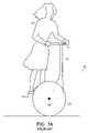
- a subject 10stands on a support platform 12 and holds a grip 14 on a handle 16 attached to the platform 12 , so that the vehicle 18 of this embodiment may be operated in a manner analogous to a scooter.
- a control loopmay be provided so that leaning of the subject results in the application of torque to wheel 20 about axle 22 thereby causing an acceleration of the vehicle.
- Vehicle 18is statically unstable, and, absent operation of the control loop to maintain dynamic stability, subject 10 will no longer be supported in a standing position and will fall from platform 12 .
- Another prior art balancing vehicleis shown in FIG.
- FIG. 1Band designated generally by numeral 24 .
- Personal vehicle 24shares the characteristics of vehicle 18 of FIG. 1A , namely a support platform 12 for supporting subject 10 and grip 14 on handle 16 attached to platform 12 , so that the vehicle 24 of this embodiment may also be operated in a manner analogous to a scooter.
- FIG. 1Bshows that while vehicle 24 may have clusters 26 each having a plurality of wheels 28 , vehicle 24 remains statically unstable and, absent operation of a control loop to maintain dynamic stability, subject 10 will no longer be supported in a standing position and may fall from platform 12 .
- a standing rider 10 of the vehicle 30places his feet on the platform and shifts weight back and forth in a relatively wide and flat path 33 .
- the slight amount of strength that is needed to resist gravity and inertia in transversing this arcis well within the strength and coordination of an average user's muscles.
- the center of gravity of the vehicle and rider 35moves in an arcuate fashion as the rider leans either forward or backward.
- movement of the center of gravity in the manner described abovemay no longer be possible and an alternative mechanism for shifting the center of gravity is required.
- the mechanismneeds to provide adequate range of motion while allowing the rider to resist gravity and inertia.
- a device for transporting a human subject over a surfaceis disclosed.
- the deviceis a dynamically balancing vehicle having a control loop for providing balance.
- the deviceincludes a platform defining a fore-aft plane.
- the platformsupports a payload including the human subject.
- a ground contacting moduleis included which may be one or more wheels.
- the ground-contacting memberis movably coupled to the platform.
- the device and any load on the devicehas a center of gravity that is defined with respect to the ground-contacting member.
- the devicefurther includes a support.
- the supportmay be a seat for supporting the subject and the support is coupled to the platform in such a manner as to permit variation of the position of the center of gravity in the fore-aft plane by translation and rotation of at least a portion of the support.
- the translation and rotation of at least a portion of the supportare mechanically coupled in one embodiment.
- the transportation devicefurther includes a drive which is coupled to the ground-contacting module and which delivers power to the ground-contacting module in a manner responsive to the position of the center of gravity.
- the drivesupplies force so as to balance the vehicle.
- the supportrotates about a virtual pivot point which lies above the support. The structure of the support allows the support to rock about an arc or other path.
- the supportmay include a mechanical linkage such as a four bar linkage.
- each bar of the four bar linkageis coupled together with pivots.
- a fifth barmay be included for holding a seat. The fifth bar is attached at one of the pivots of the four bar linkage. In another embodiment, the fifth bar is attached to one of the bars of the linkage.
- the four bar linkageforms a parallelogram and changes shape as a user of the vehicle moves on the seat shifting the center of gravity.
- the deviceincludes pressure sensors for activating the drive and causing the control loop to become active.
- the pressure sensorsmay be placed in the platform for activation or the pressure sensors may be placed in the seat.
- a mechanical contactis attached to the support which contacts the pressure sensors that are coupled to the platform.
- the supportincludes a seat that is slideably mounted.
- the supportincludes one or more rails for allowing the seat to slide.
- the seatneed not be capable of rotation in such an embodiment, but does allow for the user to change the center of gravity for controlling the vehicle.
- the sliding seatdoes rotate. As the seat slides along the rails a mechanism causes the seat to rotate.
- the railsinclude one or more sprockets that engage with protrusions that are coupled to the seat and thus cause rotation as the seat is rolled on the rails.
- the supportmay include one or more pulleys that assist the seat in sliding along the one or more rails.
- the seatis coupled to friction wheels that ride on a friction surface.
- the supportincludes a convex radial base that allows the support to rock in response to a user shifting his weight.
- the convex radial basemay be coupled to the platform at a pivot point that translates fore and aft with the motion of the seat.
- the convex radial basemay have different radii of curvature along its convex surface.
- the supportmay include a damper such as a spring to return the support to a pre-determined position.
- the supportpreferably returns to a position, such that the vehicle remains substantially stationary when no force is applied to the support. In such an embodiment, the vehicle may still move slightly as the control loop balances the vehicle.
- a controlleris either coupled to the drive or part of the drive and the controller is part of a control loop which is responsive to changes in the center of gravity.
- the seatmay be coupled to the platform by a universal pivot. In another embodiment, the seat is coupled to a control stalk.
- FIG. 1Ais a side view of a prior art dynamically balancing vehicle of the type of which an embodiment of the invention may be advantageously employed;
- FIG. 1Bis a side view of a further prior art dynamically balancing vehicle of the type of which an embodiment of the invention may be advantageously employed;
- FIG. 2is a prior art dynamically balancing vehicle having a platform that rotates in an arc
- FIG. 3shows a dynamically balancing vehicle having a seat
- FIG. 3Ashows a dynamically balancing vehicle in which the seat is coupled to a control stalk
- FIG. 3Bshows a dynamically balancing vehicle in which the seat is coupled to the platform by a pivot
- FIG. 3Cshows a dynamically balancing vehicle in which the seat is slideably mounted
- FIG. 3Dshows a dynamically balancing vehicle having a seat
- FIG. 4Ashows the seat of the dynamically balancing vehicle mounted on a four bar linkage
- FIG. 4Bshows one position of the four bar linkage as would occur if a rider leaned backwards shifting the center of gravity in the aft direction;
- FIG. 4Cshows that the four bar linkage simulates a rocking motion such that there is translation and rotation of the seat
- FIG. 4Dshows the center of gravity translating in a straight line while the seat both translates and rotates
- FIG. 4Eshows a bar linkage mechanism for translation and rotation wherein one or more bars are flexible
- FIG. 5Ais an embodiment of the dynamically balancing vehicle in which the seat is attached to a bar via a pivot;
- FIG. 5Bis an embodiment that shows the seat attached to a slider about a pivot point wherein pulleys help to control rotation;
- FIG. 5Cshows a seat that is coupled to a slider that rides on at least partially curved rails
- FIG. 5Dshows a seat coupled to a track which includes friction wheels wherein the seat both translates and rotates
- FIG. 5Eshows a support structure having a plurality of pins which will engage with recesses in the platform
- FIG. 6shows a side view of an embodiment of the dynamically balancing vehicle with a detachable rocker seat
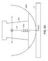
- FIG. 6Ashows the support structure attached to the platform via a simple cable under tension
- FIG. 6Bshows the support structure including a series of teeth on the bottom arced surface and also on the platform;
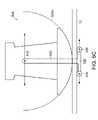
- FIG. 6Cshows the support structure coupled to the platform about a pivot point
- FIG. 7Ashows a folding seat which can be attached to a dynamically balancing vehicle wherein the seat is positioned as if a rider is sitting on the seat;
- FIG. 7Bshows a rider sitting on the folding seat
- FIG. 7Cshows the position of the folding seat when a rider engages/disengages with the vehicle
- FIG. 7Dshows an embodiment of a dynamically balancing vehicle having knee supports
- FIG. 8shows an embodiment of a support structure which includes both translational and rotational mechanical actuators.
- the balancing vehicleincludes a ground-contacting module 32 which, in the embodiment that is shown, is a pair of co-axial wheels powered by motors.
- a controlleris coupled to the motor for providing a control signal in response to changes in the center of gravity of an assembly that includes the vehicle along with a rider.
- the controller modulesenses the change in the center of gravity 36 and controls power to the wheels 32 based upon changes to the center of gravity 36 about a fore-aft plane 42 using a control loop. As the center of gravity 36 moves forward in the fore direction, power is provided to the wheels and the vehicle will move forward.
- the control moduleincludes gyroscopes for sensing changes in the position of the center of gravity.
- the vehicle that is shownincludes a platform 12 for supporting the rider and a control stalk 14 and 16 .
- Appropriate force transducersmay be provided to sense leftward and rightward leaning and related controls provided to cause left and right turning as a result of the sensed leaning.
- the leaningmay also be detected using proximity sensors.
- the vehicle of this embodimentmay be equipped with a foot- (or force-) actuated switch located on the platform 12 to activate the vehicle, in such a manner that the switch is closed so as to power the vehicle automatically when the subject contacts the platform 12 .
- This embodimentfurther includes a support 34 , 38 , 40 for the rider; the support may include a seat 34 on which the rider can rest.
- the seat 34is attached to the control stalk 16 as shown in FIG. 3A .
- the rider 10then uses his body and momentum to move the center of gravity of the combination of the vehicle and the rider in either a forward or in an aft direction.
- the seat 34is attached to the platform 12 via a pivot point 44 as shown in FIG. 3B .
- the pivotmay be a simple pivot such that the pivot moves only in the fore and aft directions or the pivot may be a universal pivot so that the seat may pivot in any direction.
- a universal pivotis a spring.
- the pivotmay be mounted to the platform along the axis of the wheels, or the pivot may be mounted at other locations such as along the rear edge of the platform.
- a seatis attached to the platform using one or more rails 46 on which the seat 34 slides as shown in FIG. 3C .
- the movement of the seat 34 by the ridercauses a change in the position of the center of gravity of the vehicle and its load. If the seat is moved in the fore direction sensors sense the resulting tilt of the vehicle and cause the vehicle to increase in speed in the fore direction. If the seat is slid in the aft direction, the vehicle 30 will slow down correspondingly.
- a centering mechanismsuch as, a spring may be incorporated with either the pivot or sliding seat, so the seat will return to a position such that the vehicle is substantially stationary when a rider disengages from the vehicle.
- a seat 50is mounted to the platform 12 .
- the seat and the linkage 52 to the platformdoes not include a pivot.
- the seat in this embodimentpreferably extends the length of the platform.
- the vehicleincludes a bar linkage mechanism, such as a four bar linkage, that is attached to the control stalk as shown in FIG. 4A .
- the four bar linkage mechanismis also attached to a seat by another bar (seat post) which is coupled to the four bar linkage about a common pivot point of the four bar linkage or coupled to a bar in the linkage.
- the four bar linkage mechanismallows the seat to move in an arc which simulates a rocking motion similar to that of a rocking chair about the base platform as shown in FIG. 4C .
- FIG. 4Bshows one position of the four bar linkage 55 as would occur if a rider leaned backwards shifting the center of gravity in the aft direction.
- the riderboth moves in the aft direction and also rotates in the aft direction and as such both, translation and rotation are coupled together.
- the four bar linkageallows the seat to move in an arc about a virtual pivot point.
- the virtual pivot pointcan be located at a point above the seat. In other embodiments, the virtual pivot point may be located below the seat.
- the center of gravity 35moves in a straight line in the fore-aft plane as shown in FIG. 4D .
- the center of gravityneed not move in a straight line and the position of the center of gravity may vary. The motion of the seat creates a rider experience that is different from the seats discussed above in FIGS. 3A-3D .
- control stalkis held by the rider by a pair of hand grips that extend from the control stalk.
- the seatcan move about the fore-aft plane and the seat will both shift and rotate when the rider moves, thus changing the center of gravity.
- FIGS. 5A-E and FIGS. 6 , 6 A, 6 B, and 6 Chave a linkage mechanism for providing the coupling of rotation and translation
- other structures and systemscould also be designed to provide this functionality such as those shown in, but not limited to FIGS. 5A-E and FIGS. 6 , 6 A, 6 B, and 6 C and the present invention is not intended to be limited to mechanical linkages.
- the four bar linkageincludes non-rigid members that can flex.
- FIG. 4Eshows a support structure where members B and C each flex and member D is rigid as are the couplings of members B and C to platform A.
- members B and Care shown such that the two members lean inwards to meet member D.
- the members B and Cwill flex such that the seat will move in a rocking motion about a virtual pivot point that lies above the seat.
- the motion of members B and Cis shown in FIG. 4E by the dotted lines. As such, member D which supports the seat will both translate and rotate.
- pivotsmay be included in such an embodiment, so that the linkage both pivots and flexes.
- pivotsmay be placed at the point where member D comes into contact with members B and C as shown in the figure.
- members B and Cmay be positioned so rather than leaning inward, the two members are outward leaning.
- the seatwill move much like a rocking chair. If a rider leans in the fore direction the seat will translate in the fore direction and the seat will rotate such that the fore-most part of the seat will be lower than the aft-most part of the seat. This is different from the embodiment that is shown in FIG. 4E wherein if a rider causes the seat to translate in the fore direction, the seat will rotate such that the fore-most part of the seat is elevated as compared to the aft-most part of the seat.
- FIGS. 5A-5Eeach show different embodiments in which both translation and rotation are coupled.
- the seat 34is attached to a bar 58 via a pivot 60 .
- the seatfurther includes a series of protrusions 62 formed in an arc which mesh with a sprocket 64 .
- the sprocket 64is attached to the bar 58 and can spin about an axis 66 .
- the barincludes a second sprocket 67 which can rotate about a central axis 69 .
- the sprockets 64 , 67each reside on a strip/track 70 that includes protrusions 72 that mesh with the sprockets 64 , 67 .
- the track on which the seat slidesmay have a different profile.
- the trackmay be convex, concave, or have a varying profile along its length. If the track has a varying profile, the rider needs to apply more force to move the seat along certain portions of the track.
- different track profilesmay be employed in order to shape the path of the center of gravity and the center of gravity need not move in a straight line.
- the seat 34attaches to a slider 75 about a pivot point 76 .
- the sliderfits on a rail 78 and the slider 75 can slide on the rail 78 .
- Attached to the slider at the seatare at least two pulleys 79 , 80 .
- the pulleys 79 , 80are positioned toward opposite ends of the seat about the slider.
- One or more wires or cables 81are attached to the seat and a fixed portion of the vehicle such as the rail. The cables 81 engage the pulleys 80 , 79 .
- the pulleyscause the seat to tilt due to changing tension in the cables.
- the cablesare coupled to either end of the rail 85 , 86 or some other component of the vehicle and also to the seat at opposite ends 83 , 84 .
- there are two separate cablesone of which runs from rail end 86 across pulley 79 and attaches to the seat at 84 .
- the second cableattaches to the seat at 83 and across pulley 80 and attaches at the rail end 85 . If the seat is moved in the aft direction, the edge of the seat in the aft direction will be rotated and lowered. Similarly, if the seat is moved by the rider in the fore direction, the fore-most part of the seat will rotate and will be lowered.
- the seatis coupled to a slider 87 about a pivot point 88 .
- the slider 87is seated on a rail 89 and provides for the seat to be slid in a fore and an aft direction.
- the seatalso includes two extensions 34 A, 34 B that each have two wheels 90 mounted thereto. Between each pair of wheels is a straight track which includes an arc 89 A, 89 B at each end of the track. As the seat is slid in either the fore or the aft direction the wheels roll along the arc and cause the seat to tilt about the pivot point. It can be imagined that the track has a varying curvature, such that the center portion of the track is itself curved and that the ends have a greater radius of curvature as compared to the center.
- the seat 34rides on a track 200 .
- the seat 34is coupled to a transmission 210 by a pivot 220 .
- the transmissionis coupled to a pair of friction wheels 225 , 230 .
- translation of the seat 34is directly coupled to rotation of the seat.
- the wheelsrotate a greater amount than the pivot rotates the seat.
- the transmissiontherefore, causes the seat to pivot/rotate at a fraction of the rotation of the friction wheels. It should be understood that all of the tracks that are shown in FIGS.
- the support structurealso will include a mechanism for holding the track at a proper seat height.
- the trackmay be mounted to the control stalk, or may sit on its own mounting structure that is coupled to the platform.
- the mounting structuremay be a shaft.
- FIG. 6shows a side view of an embodiment of the dynamically balancing vehicle with a detachable rocker seat.
- the rocker seatincludes a support structure 95 .
- the bottom portion of the support structurecontacts the platform and is shaped like an arc 97 allowing the seat 34 to rock.
- the arc shaped lower member 97 of the support structure 95is coupled to the platform 12 via a moving contact point.
- the arc shaped member 97 memberrotates equally in the fore and aft plane in this embodiment. Although in other embodiments, rotation may be limited in either the fore or aft direction.
- the support structuremay also be coupled to the platform via a pair of rails.
- the support structurerests on the rails that the rails include a mechanism that constrains the support structure from moving in any other plane other than the fore-aft plane.
- the arch shaped lower portion of the support structureis not coupled to the platform at a contact point.
- the arc shaped membermay roll on a series of rails or wheels.
- the support structuremay include a guide pin that extends through the support structure and is enclosed by the rails on either side of the support structure.
- the seatcan rock in the fore-aft direction about a virtual pivot that is above the seat. It should be understood that a virtual pivot point need not be above the seat, in certain embodiments, the virtual pivot point may exist below the seat, for example.
- the lower surface of the support structure that is formed in an arcmay have any number of radii.
- the lower surfacemay have a greater curvature at the edges and less of a curvature at its center, so that as the support structure rocks about its central portion, each unit of translation there is proportional to a degree of rotation, but as the support structure is rocked further toward the edges, there is a greater degree of rotation for each unit of translation.
- the lower surface of the support structure 150includes two pins 160 , 165 at the edges of the arc as shown in FIG. 5E .
- the support structurerocks 170 to the edge, one of the pins 160 or 165 will engage with a recess 160 A or 165 A in the platform 12 . If the rider continues to lean in the same direction, the support structure will rotate about the pin 160 or 165 .
- FIG. 6in which the support structure has an arc as the lower surface, may be coupled to the platform in any one of a number of ways.
- gravitymay hold the support structure on the platform 12 .
- the platform surface and the bottom surface of the support structuremay be formed from materials having a high coefficient of friction.
- the support structure 300may be attached to the platform 12 via a simple cable 310 under tension (including a spring 310 A).
- the spring 310 Astretches, and thus there is a restoring force returning the support structure 300 to a centered position as shown.
- FIG. 6Athe support structure 300 may be attached to the platform 12 via a simple cable 310 under tension (including a spring 310 A).
- the support structure 400may include a series of teeth 410 on the bottom arced surface 400 A and the platform 12 may include a series of mating teeth 420 for the bottom surface. As the support structure rocks the teeth of the bottom surface and of the platform interlock.
- the support structure 500is coupled to the platform 12 about a pivot point 510 .
- the pivot 510is coupled to a member 520 which extends down through the platform and which in this embodiment, rides on a pair of wheels 530 .
- the member 520is rigid.
- the support structure 500will translate and the wheels 530 will rotate on the bottom side of the platform as shown.
- the support structure 500will also rotate about the pivot point 510 due to the arched bottom side of the support structure 500 A. In this embodiment, the support structure 500 will maintain contact with the platform at all times, including over rough terrain. Again, it should be recognized, that other mechanisms for coupling the support structure to the platform can be envisioned and the present invention should not be limited by the embodiments that are shown.
- the platform of the vehicleincludes one or more pressure sensors to sense the rider either engaging or disengaging from the vehicle.
- the riderpowers-up the vehicle and engages the vehicle, the vehicles enters a balancing mode.
- a control loopis made operational that senses changes to the position of the center of gravity and that causes the vehicle to move with respect to the changes. If the vehicle includes a seat, the rider may not engage the pressure sensors because her feet may not make contact with the platform or the rider may remove her feet from the platform.
- sensorssuch as pressure sensors, may be included in the seat.
- a mechanical devicesuch as a link or tube may be employed to make contact with the platform when the rider engages the vehicle.
- FIGS. 7A-Cshows a folding seat which may be employed with the previously described vehicles.
- the seatIn FIG. 7A the seat is in full view and is positioned as if a rider is sitting on the seat. The sides of the seat expand in an outward direction like an accordion when weight is put on the seat.
- FIG. 7Bshows a rider sitting on the seat.
- FIG. 7Cshows the position of the seat when a rider 10 engages/disengages with the vehicle. If the rider is already on the vehicle, the seat 34 rises up and folds as the rider stands and the support structure 92 contracts inwardly reducing the size of the support.
- the support structure for the seatmay also include a mechanism for allowing lateral movement in a plane substantially perpendicular to the fore-aft plane of the vehicle.
- the vehiclemay include sensors to sense the lateral movement.
- the sensorscan be tied into a control loop so that if a rider leans to the right more power is applied to the left wheel allowing the vehicle to turn to the right.
- lateral movementmay not be tied to sensors and a control loop, but may simply perform the function of allowing the rider to readily shift his or her weight of over rough terrain.
- the support structuremay also include knee rests 290 as shown in FIG. 7D to allow more consistent rider coupling to the vehicle and to provide postural advantage and/or partial body support.
- FIG. 8shows another embodiment, in which the seat 34 both translates and rotates. It is preferable that translation and rotation are coupled.
- the force sensors 120sense the change.
- both a linear actuator 125 and a rotational actuator 130are engaged. If the rider shifts his weight such that more weight is provided to force sensor A than to B, the linear actuator 125 will cause translation of the seat in the fore direction. Additionally, the seat will be rotated in the fore direction by the rotational actuator 130 , such that the fore-most part of the seat will be lowered and the aft-most part of the seat will be raised.
- the embodiment as shownalso includes a linear actuator 135 that provides linear motion in the vertical direction.
- This actuator 135makes engagement and disengagement with the vehicle easier.
- both translation and rotationare controlled by mechanical actuators.
- mechanical actuatorsfor providing translation and rotation of the seat, assists individuals having a reduced strength capacity when compared to the simpler mechanical designs that require the rider to manually shift the position of the seat, to significantly shift their weight using their own strength, and to maintain a position of either leaning in the fore or in the aft direction using their muscle strength.
Landscapes
- Engineering & Computer Science (AREA)
- Mechanical Engineering (AREA)
- Chemical & Material Sciences (AREA)
- Transportation (AREA)
- Combustion & Propulsion (AREA)
- Animal Behavior & Ethology (AREA)
- Public Health (AREA)
- Veterinary Medicine (AREA)
- General Health & Medical Sciences (AREA)
- Life Sciences & Earth Sciences (AREA)
- Health & Medical Sciences (AREA)
- Motorcycle And Bicycle Frame (AREA)
- Automatic Cycles, And Cycles In General (AREA)
- Jib Cranes (AREA)
- Vehicle Body Suspensions (AREA)
- Vehicle Cleaning, Maintenance, Repair, Refitting, And Outriggers (AREA)
- Forklifts And Lifting Vehicles (AREA)
Abstract
Description
Claims (20)
Priority Applications (1)
| Application Number | Priority Date | Filing Date | Title |
|---|---|---|---|
| US11/852,767US7690447B2 (en) | 1999-08-31 | 2007-09-10 | Dynamic balancing vehicle with a seat |
Applications Claiming Priority (4)
| Application Number | Priority Date | Filing Date | Title |
|---|---|---|---|
| US09/386,686US6561294B1 (en) | 1995-02-03 | 1999-08-31 | Balancing vehicle with passive pivotable support |
| US10/436,889US7004271B1 (en) | 1999-08-31 | 2003-05-13 | Dynamic balancing vehicle with a seat |
| US11/296,878US7273116B2 (en) | 1999-08-31 | 2005-12-08 | Dynamic balancing vehicle with a seat |
| US11/852,767US7690447B2 (en) | 1999-08-31 | 2007-09-10 | Dynamic balancing vehicle with a seat |
Related Parent Applications (1)
| Application Number | Title | Priority Date | Filing Date |
|---|---|---|---|
| US11/296,878DivisionUS7273116B2 (en) | 1999-08-31 | 2005-12-08 | Dynamic balancing vehicle with a seat |
Publications (2)
| Publication Number | Publication Date |
|---|---|
| US20080035395A1 US20080035395A1 (en) | 2008-02-14 |
| US7690447B2true US7690447B2 (en) | 2010-04-06 |
Family
ID=23526621
Family Applications (4)
| Application Number | Title | Priority Date | Filing Date |
|---|---|---|---|
| US09/386,686Expired - LifetimeUS6561294B1 (en) | 1995-02-03 | 1999-08-31 | Balancing vehicle with passive pivotable support |
| US10/436,889Expired - LifetimeUS7004271B1 (en) | 1999-08-31 | 2003-05-13 | Dynamic balancing vehicle with a seat |
| US11/296,878Expired - Fee RelatedUS7273116B2 (en) | 1999-08-31 | 2005-12-08 | Dynamic balancing vehicle with a seat |
| US11/852,767Expired - Fee RelatedUS7690447B2 (en) | 1999-08-31 | 2007-09-10 | Dynamic balancing vehicle with a seat |
Family Applications Before (3)
| Application Number | Title | Priority Date | Filing Date |
|---|---|---|---|
| US09/386,686Expired - LifetimeUS6561294B1 (en) | 1995-02-03 | 1999-08-31 | Balancing vehicle with passive pivotable support |
| US10/436,889Expired - LifetimeUS7004271B1 (en) | 1999-08-31 | 2003-05-13 | Dynamic balancing vehicle with a seat |
| US11/296,878Expired - Fee RelatedUS7273116B2 (en) | 1999-08-31 | 2005-12-08 | Dynamic balancing vehicle with a seat |
Country Status (14)
| Country | Link |
|---|---|
| US (4) | US6561294B1 (en) |
| EP (1) | EP1208032B1 (en) |
| JP (1) | JP5300039B2 (en) |
| KR (1) | KR100704799B1 (en) |
| CN (1) | CN1285481C (en) |
| AT (1) | ATE310664T1 (en) |
| AU (1) | AU771532B2 (en) |
| CA (2) | CA2382360C (en) |
| DE (1) | DE60024277T8 (en) |
| HK (1) | HK1046672B (en) |
| MX (1) | MXPA02002217A (en) |
| NZ (1) | NZ517412A (en) |
| RU (1) | RU2245267C2 (en) |
| WO (1) | WO2001015962A1 (en) |
Cited By (29)
| Publication number | Priority date | Publication date | Assignee | Title |
|---|---|---|---|---|
| US20090309319A1 (en)* | 2006-03-06 | 2009-12-17 | Sterraclimb Llc | Stairclimbing and Descending Hand Truck |
| US20100023220A1 (en)* | 2007-02-02 | 2010-01-28 | Issei Nakashima | Vehicle and control method of the same |
| US20100032911A1 (en)* | 2006-03-06 | 2010-02-11 | Sterraclimb Llc | Stair-Climbing Wheeled Vehicle |
| US20100063719A1 (en)* | 2006-11-30 | 2010-03-11 | Katsunori Doi | Vehicle |
| US20120168236A1 (en)* | 2009-09-18 | 2012-07-05 | Honda Motor Co., Ltd. | Inverted pendulum type vehicle |
| US20120239284A1 (en)* | 2008-11-06 | 2012-09-20 | Segway Inc. | Apparatus and method for control of a vehicle |
| WO2012160400A1 (en) | 2011-05-23 | 2012-11-29 | University Of Zagreb | Self-balancing vehicle having only one wheel or having one segmented wheel, and method for self-balancing control of such a vehicle |
| US8694161B2 (en)* | 2010-12-23 | 2014-04-08 | Thales | Collaborative automated mobile platform |
| US20150158386A1 (en)* | 2010-07-07 | 2015-06-11 | Raoul Parienti | Foldable, ultra-lightweight tricycle having an electric motor |
| US9241851B2 (en) | 2011-10-03 | 2016-01-26 | University Of South Florida | Hands-free user interface devices |
| USD803963S1 (en) | 2016-07-20 | 2017-11-28 | Razor Usa Llc | Two wheeled board |
| USD807457S1 (en) | 2016-07-20 | 2018-01-09 | Razor Usa Llc | Two wheeled board |
| USD837323S1 (en) | 2018-01-03 | 2019-01-01 | Razor Usa Llc | Two wheeled board |
| USD840872S1 (en) | 2016-07-20 | 2019-02-19 | Razor Usa Llc | Two wheeled board |
| US10220843B2 (en) | 2016-02-23 | 2019-03-05 | Deka Products Limited Partnership | Mobility device control system |
| USD846452S1 (en) | 2017-05-20 | 2019-04-23 | Deka Products Limited Partnership | Display housing |
| US10772774B2 (en) | 2016-08-10 | 2020-09-15 | Max Mobility, Llc | Self-balancing wheelchair |
| US10802495B2 (en) | 2016-04-14 | 2020-10-13 | Deka Products Limited Partnership | User control device for a transporter |
| US10908045B2 (en) | 2016-02-23 | 2021-02-02 | Deka Products Limited Partnership | Mobility device |
| US10926756B2 (en) | 2016-02-23 | 2021-02-23 | Deka Products Limited Partnership | Mobility device |
| USD915248S1 (en) | 2017-05-20 | 2021-04-06 | Deka Products Limited Partnership | Set of toggles |
| US20210284273A1 (en)* | 2018-07-27 | 2021-09-16 | Scewo Ag | Self-balancing vehicle |
| USD941948S1 (en) | 2016-07-20 | 2022-01-25 | Razor Usa Llc | Two wheeled board |
| US11399995B2 (en) | 2016-02-23 | 2022-08-02 | Deka Products Limited Partnership | Mobility device |
| US11654995B2 (en) | 2017-12-22 | 2023-05-23 | Razor Usa Llc | Electric balance vehicles |
| US11681293B2 (en) | 2018-06-07 | 2023-06-20 | Deka Products Limited Partnership | System and method for distributed utility service execution |
| USD1047785S1 (en) | 2017-05-20 | 2024-10-22 | Deka Products Limited Partnership | Toggle control device |
| US12227257B2 (en) | 2017-04-01 | 2025-02-18 | Razor Usa Llc | Electric balance vehicles |
| US12440401B2 (en) | 2024-05-22 | 2025-10-14 | Deka Products Limited Partnership | Mobility device |
Families Citing this family (202)
| Publication number | Priority date | Publication date | Assignee | Title |
|---|---|---|---|---|
| US6561294B1 (en)* | 1995-02-03 | 2003-05-13 | Deka Products Limited Partnership | Balancing vehicle with passive pivotable support |
| US6799649B2 (en)* | 1999-03-15 | 2004-10-05 | Deka Products Limited Partnership | Control of a balancing personal vehicle |
| US7275607B2 (en) | 1999-06-04 | 2007-10-02 | Deka Products Limited Partnership | Control of a personal transporter based on user position |
| US6435535B1 (en)* | 2000-03-01 | 2002-08-20 | Deka Products Limited Partnership | Trailer for balancing vehicle |
| US6969079B2 (en)* | 2002-06-05 | 2005-11-29 | Deka Products Limited Partnership | Multiple-passenger transporter |
| US7407175B2 (en)* | 2000-03-01 | 2008-08-05 | Deka Products Limited Partnership | Multiple-passenger transporter |
| US6946650B2 (en) | 2002-03-04 | 2005-09-20 | Independence Technology, L.L.C. | Sensor |
| US6786299B2 (en)* | 2002-03-16 | 2004-09-07 | Lamar Bennett | Swivel-power scaffold mobilizing device |
| US7017686B2 (en)* | 2002-06-11 | 2006-03-28 | Deka Products Limited Partnership | Hybrid human/electric powered vehicle |
| US7210544B2 (en) | 2002-07-12 | 2007-05-01 | Deka Products Limited Partnership | Control of a transporter based on attitude |
| JP2004074814A (en)* | 2002-08-09 | 2004-03-11 | Matsushita Electric Works Ltd | Moving equipment for man |
| CN100361862C (en)* | 2002-11-20 | 2008-01-16 | 中国科学技术大学 | Self-balancing two-wheeled electric vehicle |
| USD528468S1 (en)* | 2002-11-27 | 2006-09-19 | Segway Llc | Personal transporter |
| JP4523244B2 (en)* | 2003-05-22 | 2010-08-11 | 独立行政法人科学技術振興機構 | Power-assisted mobile trolley |
| WO2005016735A1 (en)* | 2003-08-18 | 2005-02-24 | Canterprise Limited | A powered unicycle |
| JP3981733B2 (en)* | 2003-09-17 | 2007-09-26 | 独立行政法人産業技術総合研究所 | Parallel two-wheel passenger cart |
| JP4556418B2 (en)* | 2003-11-04 | 2010-10-06 | トヨタ自動車株式会社 | Traveling apparatus and control method thereof |
| USD507206S1 (en)* | 2004-03-22 | 2005-07-12 | John Baron Wang | Motor driven vehicle for transporting a standing person |
| US20070257451A1 (en)* | 2006-05-08 | 2007-11-08 | Chiba Institute Of Technology | Car, walking apparatus, and method of determining shape of wheel |
| JP4599907B2 (en)* | 2004-06-28 | 2010-12-15 | トヨタ自動車株式会社 | Traveling device |
| DE102005059361A1 (en) | 2005-02-25 | 2006-08-31 | Ulrich Kahlert | Two-wheeled battery-powered vehicle for one person |
| US8016060B2 (en)* | 2005-03-11 | 2011-09-13 | Equos Research Co., Ltd. | Vehicle |
| US20060220334A1 (en)* | 2005-03-29 | 2006-10-05 | Liao Li W | Article carrying cart |
| CN100557539C (en)* | 2005-07-26 | 2009-11-04 | 松下电器产业株式会社 | Inverted two-wheel walking robot and control method thereof |
| USD569308S1 (en)* | 2005-09-28 | 2008-05-20 | Toyota Jidosha Kabushiki Kaisha | Two wheeled vehicle |
| US8099200B2 (en)* | 2005-09-30 | 2012-01-17 | Coombs Joshua D | Vehicle interface based on the weight distribution of a user |
| US20090076686A1 (en)* | 2005-09-30 | 2009-03-19 | Jeffrey Schox | Vehicle interface to communicate a safety alert mode command |
| US20070074922A1 (en)* | 2005-09-30 | 2007-04-05 | Coombs Joshua D | Vehicle interface based on a shift of the torso of a user |
| WO2007052676A1 (en)* | 2005-11-02 | 2007-05-10 | Equos Research Co., Ltd. | Vehicle |
| EP2213562A3 (en)* | 2005-12-28 | 2011-07-06 | Equos Research Co., Ltd. | Motor vehicle |
| US7744331B2 (en)* | 2006-01-26 | 2010-06-29 | Xerox Corporation | Transport vehicle and method |
| US7757915B2 (en)* | 2006-02-03 | 2010-07-20 | Emilio Mourao | Accessory adapter for motorized personal transporter |
| US20080283311A1 (en)* | 2006-02-24 | 2008-11-20 | Tianfu Li | Balanced ball vehicle |
| KR100789906B1 (en)* | 2006-05-03 | 2008-01-02 | 안 데이비드 | Personal mobile vehicles |
| JP2007302061A (en)* | 2006-05-09 | 2007-11-22 | Equos Research Co Ltd | vehicle |
| USD551592S1 (en) | 2006-06-30 | 2007-09-25 | Segway Inc. | Human transporter |
| USD551722S1 (en)* | 2006-06-30 | 2007-09-25 | Segway Llc | Human transporter |
| JP2008024235A (en)* | 2006-07-24 | 2008-02-07 | Equos Research Co Ltd | vehicle |
| JP4957889B2 (en)* | 2006-08-29 | 2012-06-20 | 株式会社エクォス・リサーチ | Traveling vehicle |
| US7847504B2 (en)* | 2006-10-10 | 2010-12-07 | Carnegie Mellon University | Dynamic balancing mobile robot |
| JP5018039B2 (en)* | 2006-11-24 | 2012-09-05 | 株式会社エクォス・リサーチ | vehicle |
| JP5110320B2 (en)* | 2006-12-27 | 2012-12-26 | 株式会社エクォス・リサーチ | Traveling vehicle |
| RU2333862C1 (en)* | 2007-01-17 | 2008-09-20 | Александр Исаевич Черноморский | Single-axle wheel-mounted vehicle |
| US7798510B2 (en)* | 2007-02-15 | 2010-09-21 | Scott Patrick Comstock | Multi-wheeled vehicle |
| WO2008117602A1 (en)* | 2007-03-27 | 2008-10-02 | Equos Research Co., Ltd. | Vehicle |
| JP4506776B2 (en)* | 2007-04-05 | 2010-07-21 | トヨタ自動車株式会社 | Traveling device |
| US20080271938A1 (en)* | 2007-05-04 | 2008-11-06 | Benjamin Gulak | Motorized Cycle |
| JP5110267B2 (en)* | 2007-06-26 | 2012-12-26 | 株式会社エクォス・リサーチ | Traveling vehicle |
| US7748490B2 (en)* | 2007-06-26 | 2010-07-06 | University Of South Florida | Hands-free powered mobility device |
| JP5115133B2 (en)* | 2007-10-12 | 2013-01-09 | 株式会社エクォス・リサーチ | vehicle |
| USD601922S1 (en)* | 2007-10-15 | 2009-10-13 | Toyota Jidosha Kabushiki Kaisha | Two wheel folding automobile |
| JP4849103B2 (en)* | 2007-10-22 | 2012-01-11 | トヨタ自動車株式会社 | Coaxial motorcycle |
| JP4605204B2 (en)* | 2007-10-24 | 2011-01-05 | トヨタ自動車株式会社 | Inverted pendulum type moving body and control method thereof |
| US20090115149A1 (en)* | 2007-11-05 | 2009-05-07 | Wallis Scott E | Dynamic balancing personal vehicle |
| EP2093100B1 (en)* | 2007-12-03 | 2011-01-26 | Toyota Jidosha Kabushiki Kaisha | Travel gear and its controlling method |
| DE102007061708B4 (en) | 2007-12-19 | 2010-10-07 | Werner Schmidt | passenger vehicle |
| WO2009084384A1 (en)* | 2007-12-27 | 2009-07-09 | Equos Research Co., Ltd. | Vehicle |
| SI22748A (en)* | 2008-03-26 | 2009-10-31 | Aleksander Polutnik | Monocycle |
| JP2011523903A (en)* | 2008-05-21 | 2011-08-25 | ジョージア テック リサーチ コーポレイション | Force balance mobile robot system |
| US8504248B2 (en) | 2008-09-11 | 2013-08-06 | Toyota Jidosha Kabushiki Kaisha | Vehicle and its control method |
| JP4825856B2 (en)* | 2008-09-12 | 2011-11-30 | トヨタ自動車株式会社 | Mobile body and control method thereof |
| US8201653B2 (en)* | 2008-10-08 | 2012-06-19 | Strassman David R | Seats for self-balancing vehicles |
| US8800697B2 (en) | 2009-09-01 | 2014-08-12 | Ryno Motors, Inc. | Electric-powered self-balancing unicycle with steering linkage between handlebars and wheel forks |
| WO2011033574A1 (en)* | 2009-09-18 | 2011-03-24 | 本田技研工業株式会社 | Inverted pendulum type moving body |
| JP5325723B2 (en)* | 2009-09-18 | 2013-10-23 | 本田技研工業株式会社 | Vehicle saddle and inverted pendulum type moving body |
| US8443920B2 (en)* | 2009-09-18 | 2013-05-21 | Honda Motor Co., Ltd. | Inverted pendulum type vehicle |
| JP5386283B2 (en)* | 2009-09-18 | 2014-01-15 | 本田技研工業株式会社 | Inverted pendulum type moving body, control device, and control method |
| JP5337649B2 (en)* | 2009-09-18 | 2013-11-06 | 本田技研工業株式会社 | Inverted pendulum type vehicle |
| WO2011033575A1 (en)* | 2009-09-18 | 2011-03-24 | 本田技研工業株式会社 | Inverted pendulum type moving body |
| FR2952029B1 (en)* | 2009-10-30 | 2011-12-23 | Commissariat Energie Atomique | VEHICLE FORMING GYROPODE WITH INTEGRATED PHOTOVOLTAIC MODULE |
| EP2539216B1 (en)* | 2010-02-26 | 2015-09-02 | Segway Inc. | Apparatus and method for control of a vehicle |
| US8807250B2 (en)* | 2010-03-09 | 2014-08-19 | Shane Chen | Powered single-wheeled self-balancing vehicle for standing user |
| CN101817386B (en)* | 2010-03-26 | 2013-01-16 | 西安理工大学 | Electric tricycle eliminating tricycle body inertia force by using human body self-balance |
| JP5025836B2 (en)* | 2010-09-13 | 2012-09-12 | パナソニック株式会社 | Boarding type mobile body and control method for boarding type mobile body |
| WO2012136798A1 (en) | 2011-04-05 | 2012-10-11 | Ulrich Kahlert | Two-wheel battery-powered vehicle |
| US9504909B2 (en)* | 2011-05-05 | 2016-11-29 | Qualcomm Incorporated | Method and apparatus of proximity and stunt recording for outdoor gaming |
| CN102442319B (en)* | 2011-11-22 | 2014-08-20 | 冯政 | Mine walking aid |
| RU2478056C1 (en)* | 2011-12-07 | 2013-03-27 | Николай Петрович Дядченко | Transport facility |
| AU2013285622A1 (en)* | 2012-02-09 | 2014-07-31 | Kevin Thomas Halsall | Powered mobility device |
| US9235241B2 (en) | 2012-07-29 | 2016-01-12 | Qualcomm Incorporated | Anatomical gestures detection system using radio signals |
| US9085334B2 (en) | 2012-08-22 | 2015-07-21 | Ryno Motors, Inc. | Electric-powered self-balancing unicycle |
| EP2910460B1 (en)* | 2012-10-16 | 2018-02-21 | Toyota Jidosha Kabushiki Kaisha | Inverted mobile body and control method thereof |
| JP5470507B1 (en)* | 2013-01-23 | 2014-04-16 | 国亮 佐藤 | Single-seat mobile device |
| WO2014153158A1 (en) | 2013-03-14 | 2014-09-25 | Icon Health & Fitness, Inc. | Strength training apparatus with flywheel and related methods |
| TWI501897B (en)* | 2013-04-02 | 2015-10-01 | Kwang Yang Motor Co | Personal transport vehicle |
| USD739307S1 (en) | 2013-04-30 | 2015-09-22 | Ryno Motors, Inc. | One-wheeled vehicle |
| DE202014010649U1 (en)* | 2013-05-06 | 2016-02-26 | Future Motion, Inc. | Self-stabilizing skateboard |
| RU2542840C2 (en)* | 2013-06-07 | 2015-02-27 | Борис Абрамович Лабковский | Transport facility |
| GB2515794B (en)* | 2013-07-04 | 2015-06-10 | Velofeet Ltd | Improvements Relating to Vehicles |
| CN103407528A (en)* | 2013-07-24 | 2013-11-27 | 钟淑娣 | Self-balancing electric unicycle with retractable handle |
| ITBG20130021A1 (en)* | 2013-08-09 | 2015-02-10 | Supermarioway S R L | MEANS OF ELECTRIC LOCOMOTION |
| US9682732B2 (en) | 2013-09-06 | 2017-06-20 | Jason Thomas Strack | Fully self-balanced hands-free portable vehicle |
| JP6090125B2 (en)* | 2013-11-15 | 2017-03-08 | トヨタ自動車株式会社 | vehicle |
| US9481423B2 (en)* | 2013-12-09 | 2016-11-01 | Shane Chen | Single-wheel structure transportation device with extendable walking handle |
| CN105848733B (en) | 2013-12-26 | 2018-02-13 | 爱康保健健身有限公司 | Magnetic resistance mechanism in hawser apparatus |
| KR101529971B1 (en)* | 2014-01-27 | 2015-06-26 | 주식회사 로보쓰리 | The backpack type a self balancing scooter with a steering mechanism using foot |
| USD748533S1 (en) | 2014-02-12 | 2016-02-02 | Segway, Inc. | Human transporter |
| CN104859770A (en)* | 2014-02-24 | 2015-08-26 | 嘉兴斯麦龙电子科技有限公司 | Transformable self-balancing two-wheeled electric vehicle |
| US10433612B2 (en) | 2014-03-10 | 2019-10-08 | Icon Health & Fitness, Inc. | Pressure sensor to quantify work |
| WO2015191445A1 (en) | 2014-06-09 | 2015-12-17 | Icon Health & Fitness, Inc. | Cable system incorporated into a treadmill |
| US9937973B2 (en) | 2014-07-28 | 2018-04-10 | Shane Chen | Fore-aft self-balancing transportation device with low and centered foot platform |
| RU2601485C2 (en)* | 2014-08-25 | 2016-11-10 | Александр Поликарпович Лялин | Single-axle vehicle |
| CN207401118U (en) | 2014-11-05 | 2018-05-25 | 未来动力公司 | Electric vehicle |
| WO2016106372A1 (en) | 2014-12-23 | 2016-06-30 | Razor Usa Llc | Powered unicycle with handle |
| CN105947047A (en)* | 2014-12-25 | 2016-09-21 | 李陈 | Center-of-gravity self-regulated self-balancing unicycle |
| CN104494751B (en)* | 2014-12-25 | 2017-01-25 | 李陈 | A self-balancing unicycle with the function of automatically adjusting the center of gravity |
| CN106080874A (en)* | 2014-12-25 | 2016-11-09 | 李陈 | A kind of self-balancing wheelbarrow with center of gravity self-regulating function |
| US10258828B2 (en) | 2015-01-16 | 2019-04-16 | Icon Health & Fitness, Inc. | Controls for an exercise device |
| CN105867394A (en)* | 2015-01-21 | 2016-08-17 | 常州爱尔威智能科技有限公司 | Self-balancing electric vehicle operation control method and device thereof |
| CN104627289A (en)* | 2015-02-12 | 2015-05-20 | 上海战诚电子科技有限公司 | Electric-driven wheelbarrow |
| DE102015105324A1 (en)* | 2015-04-08 | 2016-10-13 | Ujet Vehicles S.À.R.L. | Motor-driven vehicle, in particular two-wheeled vehicle |
| DE102015105331B4 (en) | 2015-04-08 | 2023-02-16 | Ujet S.A. | Electric Scooter |
| US10953305B2 (en) | 2015-08-26 | 2021-03-23 | Icon Health & Fitness, Inc. | Strength exercise mechanisms |
| US10252724B2 (en) | 2015-09-24 | 2019-04-09 | P&N Phc, Llc | Portable two-wheeled self-balancing personal transport vehicle |
| CN106627895B (en) | 2016-11-25 | 2020-01-07 | 杭州骑客智能科技有限公司 | Human-computer interaction somatosensory vehicle and control method and device thereof |
| US11260905B2 (en) | 2015-10-10 | 2022-03-01 | Hangzhou Chic Intelligent Technology Co., Ltd. | Human-machine interaction vehicle |
| US9598136B1 (en)* | 2015-11-02 | 2017-03-21 | Robo3 Co., Ltd. | Self balancing scooter steered with thigh |
| USD816119S1 (en)* | 2015-11-12 | 2018-04-24 | Ninebot (Beijing) Tech. Co., Ltd | Intelligent carrying robot |
| TWI647136B (en)* | 2015-12-30 | 2019-01-11 | 凌通科技股份有限公司 | Direction control method for self-balancing electric vehicle and electric vehicle using the same |
| US9598141B1 (en) | 2016-03-07 | 2017-03-21 | Future Motion, Inc. | Thermally enhanced hub motor |
| US10112680B2 (en) | 2016-03-07 | 2018-10-30 | Future Motion, Inc. | Thermally enhanced hub motor |
| US10493349B2 (en) | 2016-03-18 | 2019-12-03 | Icon Health & Fitness, Inc. | Display on exercise device |
| US10561894B2 (en) | 2016-03-18 | 2020-02-18 | Icon Health & Fitness, Inc. | Treadmill with removable supports |
| US10625137B2 (en) | 2016-03-18 | 2020-04-21 | Icon Health & Fitness, Inc. | Coordinated displays in an exercise device |
| US10272317B2 (en) | 2016-03-18 | 2019-04-30 | Icon Health & Fitness, Inc. | Lighted pace feature in a treadmill |
| US10293211B2 (en) | 2016-03-18 | 2019-05-21 | Icon Health & Fitness, Inc. | Coordinated weight selection |
| DE112016006507T5 (en)* | 2016-03-23 | 2018-12-06 | Ford Global Technologies, Llc | VERBERGBARER MOTORROLLER |
| GB2563803B (en)* | 2016-03-23 | 2021-08-04 | Ford Global Tech Llc | Versatile urban electric transport device and system |
| US10252109B2 (en) | 2016-05-13 | 2019-04-09 | Icon Health & Fitness, Inc. | Weight platform treadmill |
| CN214209404U (en) | 2016-06-02 | 2021-09-17 | 未来动力公司 | Electric vehicle, self-balancing electric vehicle and electric skateboard |
| US10441844B2 (en) | 2016-07-01 | 2019-10-15 | Icon Health & Fitness, Inc. | Cooling systems and methods for exercise equipment |
| US10471299B2 (en) | 2016-07-01 | 2019-11-12 | Icon Health & Fitness, Inc. | Systems and methods for cooling internal exercise equipment components |
| USD836728S1 (en) | 2016-08-30 | 2018-12-25 | Ninebot (Beijing) Tech, Co., Ltd | Electric balance scooter |
| US10500473B2 (en) | 2016-10-10 | 2019-12-10 | Icon Health & Fitness, Inc. | Console positioning |
| WO2018071552A1 (en) | 2016-10-11 | 2018-04-19 | Future Motion, Inc. | Suspension system for one-wheeled vehicle |
| US10376736B2 (en) | 2016-10-12 | 2019-08-13 | Icon Health & Fitness, Inc. | Cooling an exercise device during a dive motor runway condition |
| US10293676B2 (en) | 2016-10-18 | 2019-05-21 | Piaggio Fast Forward, Inc. | Vehicle having non-axial drive |
| JP2020503204A (en) | 2016-10-18 | 2020-01-30 | ピアジオ ファスト フォワード インク | Vehicle with off-axis drive and stabilization system |
| US10173738B2 (en) | 2016-10-18 | 2019-01-08 | Piaggio Fast Forward, Inc. | Vehicle having stabilization system |
| US9999827B2 (en) | 2016-10-25 | 2018-06-19 | Future Motion, Inc. | Self-balancing skateboard with strain-based controls and suspensions |
| TWI646997B (en) | 2016-11-01 | 2019-01-11 | 美商愛康運動與健康公司 | Distance sensor for console positioning |
| US10661114B2 (en) | 2016-11-01 | 2020-05-26 | Icon Health & Fitness, Inc. | Body weight lift mechanism on treadmill |
| USD862551S1 (en) | 2016-11-21 | 2019-10-08 | Ninebot (Beijing) Tech. Co., Ltd | Head for mobile service robot |
| USD837855S1 (en)* | 2016-11-21 | 2019-01-08 | Ninebot(Beijing)Tech. Co., Ltd. | Mobile service robot |
| USD839334S1 (en)* | 2016-11-21 | 2019-01-29 | Ninebot (Beijing) Tech. Co., Ltd | Body for mobile service robot |
| TWI680782B (en) | 2016-12-05 | 2020-01-01 | 美商愛康運動與健康公司 | Offsetting treadmill deck weight during operation |
| USD890024S1 (en) | 2016-12-06 | 2020-07-14 | Piaggio Fast Forward, Inc. | Vehicle |
| USD821517S1 (en) | 2017-01-03 | 2018-06-26 | Future Motion, Inc. | Skateboard |
| EP3592636B1 (en)* | 2017-03-09 | 2022-04-06 | Shane Chen | Auto-balancing vehicle with independent wheel control |
| CN107010146B (en)* | 2017-04-06 | 2022-11-18 | 陆任行 | Balance assistant device |
| USD833538S1 (en)* | 2017-04-26 | 2018-11-13 | Oliver Evans | Self-balancing vehicle |
| CN106963571B (en)* | 2017-05-03 | 2018-07-13 | 江苏师范大学 | A kind of Multifunctional walking-assistant tool |
| KR101984169B1 (en)* | 2017-06-12 | 2019-05-31 | 어메이징썬 주식회사 | Two foot electromotion wheel |
| KR101984168B1 (en)* | 2017-06-12 | 2019-05-31 | 어메이징썬 주식회사 | One foot electromotion wheel |
| WO2018231653A1 (en) | 2017-06-14 | 2018-12-20 | Drossman Andrew Michael | Self-balancing personal vehicle with suspended harness assembly |
| CN107184326B (en)* | 2017-06-26 | 2019-06-11 | 江苏正辰智能科技有限公司 | A multipurpose folding electric wheelchair |
| USD835544S1 (en) | 2017-07-19 | 2018-12-11 | Ninebot (Beijing) Tech. Co., Ltd | Balance scooter |
| US11451108B2 (en) | 2017-08-16 | 2022-09-20 | Ifit Inc. | Systems and methods for axial impact resistance in electric motors |
| IT201700114497A1 (en) | 2017-10-11 | 2019-04-11 | Piaggio Fast Forward Inc | TWO-WHEEL VEHICLE WITH LINEAR STABILIZATION SYSTEM |
| WO2019109102A1 (en) | 2017-12-01 | 2019-06-06 | Future Motion, Inc. | Control system for electric vehicles |
| US10010784B1 (en) | 2017-12-05 | 2018-07-03 | Future Motion, Inc. | Suspension systems for one-wheeled vehicles |
| WO2019113537A1 (en) | 2017-12-07 | 2019-06-13 | Future Motion, Inc. | Dismount controls for one-wheeled vehicle |
| US10729965B2 (en) | 2017-12-22 | 2020-08-04 | Icon Health & Fitness, Inc. | Audible belt guide in a treadmill |
| CN108327825A (en)* | 2018-01-23 | 2018-07-27 | 罗弟容 | New bicycle |
| USD843532S1 (en) | 2018-02-23 | 2019-03-19 | Future Motion, Inc. | Skateboard |
| USD850552S1 (en) | 2018-02-23 | 2019-06-04 | Future Motion, Inc. | Skateboard |
| WO2019213264A1 (en) | 2018-05-01 | 2019-11-07 | Piaggio Fast Forward, Inc. | Method for determining self-driving vehicle behavior models, a self-driving vehicle, and a method of navigating a self-driving vehicle |
| EP3597164A1 (en) | 2018-07-19 | 2020-01-22 | Permobil AB | Mobility device |
| ES2881074T3 (en)* | 2018-07-19 | 2021-11-26 | Permobil Ab | Mobility device |
| KR20210078498A (en) | 2018-10-22 | 2021-06-28 | 피아지오 패스트 포워드 인코포레이티드 | Displacement device assembly and mobile carrier having same |
| USD911405S1 (en) | 2018-10-22 | 2021-02-23 | Piaggio Fast Forward, Inc. | Mobile carrier |
| CN109572896B (en)* | 2018-11-22 | 2020-09-25 | 杭州绿丞科技有限公司 | Single-wheel electric balance vehicle with labor-saving driving function |
| KR102598963B1 (en) | 2018-12-13 | 2023-11-06 | 현대자동차주식회사 | Personal mobility |
| WO2020146420A1 (en) | 2019-01-07 | 2020-07-16 | Future Motion, Inc. | Self-balancing systems for electric vehicles |
| USD923681S1 (en)* | 2019-01-30 | 2021-06-29 | Lg Electronics Inc. | Interactive personal robot for home use |
| US10456658B1 (en) | 2019-02-11 | 2019-10-29 | Future Motion, Inc. | Self-stabilizing skateboard |
| USD936719S1 (en)* | 2019-02-20 | 2021-11-23 | Lg Electronics Inc. | Home hub robot |
| USD890280S1 (en) | 2019-03-11 | 2020-07-14 | Future Motion, Inc. | Rider detection sensor for electric vehicle |
| USD889577S1 (en) | 2019-03-11 | 2020-07-07 | Future Motion, Inc. | Rotatable handle for electric vehicle |
| USD886929S1 (en) | 2019-03-11 | 2020-06-09 | Future Motion, Inc. | Rear bumper for electric vehicle |
| USD881308S1 (en) | 2019-03-11 | 2020-04-14 | Future Motion, Inc. | Fender for electric vehicle |
| USD890279S1 (en) | 2019-03-11 | 2020-07-14 | Future Motion, Inc. | Electric vehicle with fender |
| USD888175S1 (en) | 2019-03-11 | 2020-06-23 | Future Motion, Inc. | Electric vehicle front |
| USD881307S1 (en) | 2019-03-11 | 2020-04-14 | Future Motion, Inc. | Fender for electric vehicle |
| USD890278S1 (en) | 2019-03-11 | 2020-07-14 | Future Motion, Inc. | Electric vehicle |
| USD897469S1 (en) | 2019-03-11 | 2020-09-29 | Future Motion, Inc. | Foot pad for electric vehicle |
| CN110466656B (en)* | 2019-08-05 | 2020-08-11 | 安徽众星电气科技有限公司 | Special balance car of high-voltage transformer installation |
| USD941900S1 (en)* | 2019-08-13 | 2022-01-25 | Ninebot (Beijing) Tech. Co. Ltd. | Robot for delivery |
| USD939602S1 (en)* | 2019-08-15 | 2021-12-28 | Ninebot (Beijing) Tech. Co., Ltd | Robot for delivery |
| KR20210065656A (en) | 2019-11-27 | 2021-06-04 | 현대자동차주식회사 | Variable wheeled vehicle |
| USD947916S1 (en)* | 2020-03-04 | 2022-04-05 | Forwardx Robotics, Inc. | Autonomy transportation vehicle with a liftable platform |
| JP2021142588A (en)* | 2020-03-10 | 2021-09-24 | 本田技研工業株式会社 | Operation system for moving body |
| CN111923061B (en)* | 2020-08-11 | 2023-12-01 | 行星算力(深圳)科技有限公司 | wheeled transport robot |
| US12005340B2 (en) | 2020-10-06 | 2024-06-11 | Future Motion, Inc. | Suspension systems for an electric skateboard |
| GB2598169B (en)* | 2020-12-22 | 2022-12-07 | Body Rocket Ltd | Sensor arrangements |
| CN214356465U (en)* | 2020-12-29 | 2021-10-08 | 美国锐哲有限公司 | Single-wheel electric balance car |
| KR102397304B1 (en)* | 2021-02-03 | 2022-05-13 | 어메이징썬 주식회사 | Self-powered motorcycles and bicycles |
| KR102383060B1 (en)* | 2021-02-09 | 2022-04-08 | 어메이징썬 주식회사 | Electric kickboard |
| US11273364B1 (en) | 2021-06-30 | 2022-03-15 | Future Motion, Inc. | Self-stabilizing skateboard |
| US11299059B1 (en) | 2021-10-20 | 2022-04-12 | Future Motion, Inc. | Self-stabilizing skateboard |
| US11890528B1 (en) | 2022-11-17 | 2024-02-06 | Future Motion, Inc. | Concave side rails for one-wheeled vehicles |
| US12187373B1 (en) | 2024-02-29 | 2025-01-07 | Future Motion, Inc. | Skateboard footpads having foot engagement structures and traction inserts |
Citations (129)
| Publication number | Priority date | Publication date | Assignee | Title |
|---|---|---|---|---|
| US243161A (en) | 1881-06-21 | John w | ||
| US584127A (en) | 1897-06-08 | Edmond draullette and ernest catois | ||
| US734109A (en) | 1901-09-20 | 1903-07-21 | Henry Tolcher | Monocycle. |
| US849270A (en) | 1906-05-15 | 1907-04-02 | Andrew Schafer | Truck. |
| GB152664A (en) | 1919-05-08 | 1922-01-19 | Giuseppe Garanzini | Improved wheels for vehicles intended to move over soft ground |
| FR980237A (en) | 1949-02-07 | 1951-05-09 | Baby carriage or crawler stroller | |
| US2742973A (en) | 1952-02-01 | 1956-04-24 | Johannesen Hans Arne Ingolf | Powered invalid chair and handle control therefor |
| US3145797A (en) | 1960-09-21 | 1964-08-25 | Charles F Taylor | Vehicle |
| US3260324A (en) | 1963-11-12 | 1966-07-12 | Caesar R Suarez | Motorized unicycle |
| US3283398A (en) | 1962-04-26 | 1966-11-08 | Artos Engineering Co | Art of producing electrical conductors from cord wire |
| US3288234A (en) | 1964-08-17 | 1966-11-29 | Jack M Feliz | Stair climbing conveyance |
| US3348518A (en) | 1965-10-13 | 1967-10-24 | Lockheed Aircraft Corp | Amphibious star-wheeled vehicle |
| US3374845A (en) | 1966-05-05 | 1968-03-26 | Selwyn Donald | Command control system for vehicles |
| US3399742A (en) | 1966-06-23 | 1968-09-03 | Franklin S. Malick | Powered unicycle |
| US3446304A (en) | 1966-08-08 | 1969-05-27 | Constantin Alimanestiand | Portable conveyor |
| US3450219A (en) | 1967-03-13 | 1969-06-17 | John F Fleming | Stair-climbing vehicle |
| US3515401A (en) | 1968-11-06 | 1970-06-02 | Eshcol S Gross | Stair climbing dolly |
| GB1213930A (en) | 1969-05-29 | 1970-11-25 | John Fay Fleming | A vehicle for climbing stairs |
| US3580344A (en) | 1968-12-24 | 1971-05-25 | Johnnie E Floyd | Stair-negotiating wheel chair or an irregular-terrain-negotiating vehicle |
| US3596298A (en) | 1969-05-14 | 1971-08-03 | John A Durst Jr | Lifting device |
| US3682509A (en) | 1969-12-29 | 1972-08-08 | Troxel Mfg Co | Truss for a bicycle saddle and method of making same |
| US3860264A (en) | 1973-01-15 | 1975-01-14 | Mattel Inc | Lean velocipede |
| US3872945A (en) | 1974-02-11 | 1975-03-25 | Falcon Research And Dev Co | Motorized walker |
| US3907051A (en) | 1972-03-20 | 1975-09-23 | Arthur Schwartz | Stand-up wheelchair |
| US3952822A (en) | 1973-03-19 | 1976-04-27 | Stiftelsen Teknisk Hjalp At Handikappade Permobilstiftelsen | Electrically powered wheel-chair for indoor and outdoor use |
| US4018440A (en) | 1975-03-31 | 1977-04-19 | Deutsch Fritz A | Invalid walker with wheel control mechanism |
| US4062558A (en) | 1976-07-19 | 1977-12-13 | David Wasserman | Unicycle |
| US4076270A (en) | 1976-01-19 | 1978-02-28 | General Motors Corporation | Foldable cambering vehicle |
| US4088199A (en) | 1976-02-23 | 1978-05-09 | Wolfgang Trautwein | Stabilized three-wheeled vehicle |
| US4094372A (en) | 1977-02-28 | 1978-06-13 | Notter Michael A | Motorized skateboard with uni-directional rear mounting |
| US4109741A (en) | 1977-07-29 | 1978-08-29 | Gabriel Charles L | Motorized unicycle wheel |
| US4111445A (en) | 1977-06-09 | 1978-09-05 | Kenneth Haibeck | Device for supporting a paraplegic in an upright position |
| US4151892A (en) | 1976-04-28 | 1979-05-01 | Frank Francken | Motorized terrestrial surf-board |
| US4155590A (en) | 1977-12-02 | 1979-05-22 | Cunningham Charles B | Bicycle seat post |
| US4222449A (en) | 1978-06-08 | 1980-09-16 | Feliz Jack M | Step-climbing wheel chair |
| US4241931A (en) | 1979-04-16 | 1980-12-30 | Healy Donald H | Automobile tire riding vehicle |
| US4264082A (en) | 1979-03-26 | 1981-04-28 | Fouchey Jr Charles J | Stair climbing cart |
| US4266627A (en) | 1978-02-22 | 1981-05-12 | Willy Habegger | Traveling assembly and wheel suspension for a rolling and stepping vehicle |
| US4293052A (en) | 1978-07-17 | 1981-10-06 | Daswick Alexander C | Lightweight two-wheeled vehicle |
| US4325565A (en) | 1980-03-03 | 1982-04-20 | General Motors Corporation | Cambering vehicle |
| FR2502090A1 (en) | 1981-03-17 | 1982-09-24 | Tobex Motivated Chair Cy Ltd | VEHICLE FOR GOING UP AND DOWN FROM STAIRS |
| US4354569A (en) | 1979-04-14 | 1982-10-19 | Heinz Eichholz | Electric vehicle |
| US4363493A (en) | 1980-08-29 | 1982-12-14 | Veneklasen Paul S | Uni-wheel skate |
| DE3128112A1 (en) | 1981-07-16 | 1983-02-03 | Gerhard Dipl.-Ing. 6100 Darmstadt Heid | Small electric vehicle |
| US4373600A (en) | 1980-07-18 | 1983-02-15 | Veda, Inc. | Three wheel drive vehicle |
| US4375840A (en) | 1981-09-23 | 1983-03-08 | Campbell Jack L | Mobile support |
| DE3242880A1 (en) | 1981-11-20 | 1983-06-23 | T.G.R. S.R.L., Ozzano Dell' Emilia | Cart with electrical drive, particularly suitable for transporting heavy and bulky objects on steps |
| DE2048593C2 (en) | 1969-10-04 | 1984-09-06 | Deres Development Corp., Greenwich, Conn. | Mechanical support device, in particular for supporting the human body |
| DE3411489A1 (en) | 1983-03-29 | 1984-10-04 | Aisin Seiki K.K., Kariya, Aichi | DEVICE FOR OPERATING A MEDICAL DEVICE |
| GB2139576A (en) | 1983-05-13 | 1984-11-14 | Mavispace Ltd | Stair climbing devices |
| US4510956A (en) | 1983-08-15 | 1985-04-16 | Lorraine King | Walking aid, particularly for handicapped persons |
| US4560022A (en) | 1983-07-22 | 1985-12-24 | Kassai Kabushikikaisha | Electrically driven children's vehicle |
| US4566707A (en) | 1981-11-05 | 1986-01-28 | Nitzberg Leonard R | Wheel chair |
| US4570078A (en) | 1982-05-27 | 1986-02-11 | Honda Giken Kogyo Kabushiki Kaisha | Switch assembly for a motor vehicle |
| US4571844A (en) | 1982-06-09 | 1986-02-25 | Jeco Co., Ltd. | Angle change detector |
| US4624469A (en) | 1985-12-19 | 1986-11-25 | Bourne Jr Maurice W | Three-wheeled vehicle with controlled wheel and body lean |
| US4657272A (en) | 1985-09-11 | 1987-04-14 | Davenport James M | Wheeled vehicle |
| EP0109927B1 (en) | 1982-10-19 | 1987-06-03 | von Rohr, Martin | Wheel assembly |
| US4685693A (en) | 1986-09-16 | 1987-08-11 | Vadjunec Carl F | Upright wheelchair |
| US4709772A (en) | 1985-01-31 | 1987-12-01 | Pierre Brunet | Motorized moving device |
| US4716980A (en) | 1986-02-14 | 1988-01-05 | The Prime Mover Company | Control system for rider vehicles |
| US4740001A (en) | 1981-09-14 | 1988-04-26 | Torleumke Keith R | Sprag wheel |
| US4746132A (en) | 1987-02-06 | 1988-05-24 | Eagan Robert W | Multi-wheeled cycle |
| US4757868A (en) | 1986-05-09 | 1988-07-19 | Cresswell Thomas A | Disassemblable vehicle for attachment to a powered, steerable front wheel and components for rigidly holding the vehicle in assembled condition |
| US4770410A (en) | 1986-07-03 | 1988-09-13 | Brown Guies L | Walker |
| US4786069A (en) | 1986-06-30 | 1988-11-22 | Tang Chun Yi | Unicycle |
| US4790400A (en) | 1986-07-24 | 1988-12-13 | Eric Sheeter | Stepping vehicle |
| US4790548A (en) | 1987-05-04 | 1988-12-13 | Fabien Decelles | Climbing and descending vehicle |
| US4794999A (en) | 1985-06-25 | 1989-01-03 | Robert Hester | Wheelchair and method of operating same |
| US4798255A (en) | 1987-10-29 | 1989-01-17 | Wu Donald P H | Four-wheeled T-handlebar invalid carriage |
| US4802542A (en) | 1986-08-25 | 1989-02-07 | Falcon Rehabilitation Products, Inc. | Powered walker |
| US4809804A (en) | 1986-08-25 | 1989-03-07 | Falcon Rehabilitation Products, Inc. | Combination wheelchair and walker apparatus |
| US4834200A (en) | 1986-12-15 | 1989-05-30 | Agency Of Industrial Science & Technology | Method and apparatus for dynamic walking control of robot |
| US4863182A (en) | 1988-07-21 | 1989-09-05 | Chern Jiuun F | Skate bike |
| US4867188A (en) | 1986-01-28 | 1989-09-19 | Michael Reid | Orthopaedic trolley |
| US4869279A (en) | 1986-12-22 | 1989-09-26 | Hedges Harry S | Walker |
| US4874055A (en) | 1987-12-16 | 1989-10-17 | Beer Robin F C | Chariot type golf cart |
| US4890853A (en) | 1988-03-07 | 1990-01-02 | Luanne Olson | Wheelchair walker |
| US4909525A (en) | 1989-01-13 | 1990-03-20 | Michael Flowers | Convertible personal vehicle having a take-apart frame |
| US4919225A (en) | 1988-03-31 | 1990-04-24 | Sturges Daniel D | Platform oriented transportation vehicle |
| US4944360A (en) | 1988-03-31 | 1990-07-31 | Sturges Daniel D | Platform oriented transportation vehicle |
| US4953851A (en) | 1988-11-07 | 1990-09-04 | Sherlock Lila A | Safety mobilizer walker |
| US4984754A (en) | 1986-07-28 | 1991-01-15 | Arthur Yarrington | Heli-hover amphibious surface effect vehicle |
| US4985947A (en) | 1990-05-14 | 1991-01-22 | Ethridge Kenneth L | Patient assist device |
| US4998596A (en) | 1989-05-03 | 1991-03-12 | Ufi, Inc. | Self-propelled balancing three-wheeled vehicle |
| US5002295A (en) | 1990-04-19 | 1991-03-26 | Pro-China Sporting Goods Industries Inc. | Unicycle having an eccentric wheel |
| US5011171A (en) | 1990-04-20 | 1991-04-30 | Cook Walter R | Self-propelled vehicle |
| US5020624A (en) | 1989-11-13 | 1991-06-04 | Everest & Jennings, Inc. | Power drive scooter |
| US5048891A (en) | 1989-10-30 | 1991-09-17 | Yach Thomas L | Seat position changing apparatus for a bicycle or cycle-type machine |
| US5052237A (en) | 1989-05-17 | 1991-10-01 | Aluweld S.A. | Transmission device |
| US5111899A (en) | 1989-05-17 | 1992-05-12 | Aluweld S.A. | Motorized rolling-chair |
| US5158493A (en) | 1991-05-30 | 1992-10-27 | Richard Morgrey | Remote controlled, multi-legged, walking robot |
| US5168947A (en) | 1991-04-09 | 1992-12-08 | Rodenborn Eugene P | Motorized walker |
| US5171173A (en) | 1990-07-24 | 1992-12-15 | Zebco Corporation | Trolling motor steering and speed control |
| US5186270A (en) | 1991-10-24 | 1993-02-16 | Massachusetts Institute Of Technology | Omnidirectional vehicle |
| US5221883A (en) | 1990-11-30 | 1993-06-22 | Honda Giken Kogyo Kabushiki Kaisha | System for controlling locomotion of legged walking robot |
| US5241875A (en) | 1990-09-24 | 1993-09-07 | Uwe Kochanneck | Multiblock-robot |
| US5248007A (en) | 1989-11-21 | 1993-09-28 | Quest Technologies, Inc. | Electronic control system for stair climbing vehicle |
| US5314034A (en) | 1991-11-14 | 1994-05-24 | Chittal Nandan R | Powered monocycle |
| US5350033A (en) | 1993-04-26 | 1994-09-27 | Kraft Brett W | Robotic inspection vehicle |
| US5366036A (en) | 1993-01-21 | 1994-11-22 | Perry Dale E | Power stand-up and reclining wheelchair |
| US5376868A (en) | 1991-04-01 | 1994-12-27 | Aisin Aw Co., Ltd. | Driving force controller for electric motor vehicle |
| US5419624A (en) | 1990-11-24 | 1995-05-30 | Mannesmann Aktiengesellschaft | Arrangement for detecting a critical driving torque in a motor vehicle |
| US5701968A (en) | 1995-04-03 | 1997-12-30 | Licile Salter Packard Children's Hospital At Stanford | Transitional power mobility aid for physically challenged children |
| US5701965A (en) | 1993-02-24 | 1997-12-30 | Deka Products Limited Partnership | Human transporter |
| US5775452A (en) | 1996-01-31 | 1998-07-07 | Patmont Motor Werks | Electric scooter |
| DE29808091U1 (en) | 1998-05-06 | 1998-08-27 | Brecht, Thomas, 76646 Bruchsal | Screw-on profile part rail brackets |
| DE29808096U1 (en) | 1998-05-06 | 1998-08-27 | Brecht, Thomas, 76646 Bruchsal | Electric motor powered wheelchair suitable for stairs |
| US5971091A (en) | 1993-02-24 | 1999-10-26 | Deka Products Limited Partnership | Transportation vehicles and methods |
| US5973463A (en) | 1996-09-10 | 1999-10-26 | Toyota Jidosha Kabushiki Kaisha | Driving controller for electric vehicle |
| US5975225A (en) | 1993-02-24 | 1999-11-02 | Deka Products Limited Partnership | Transportation vehicles with stability enhancement using CG modification |
| US5986221A (en) | 1996-12-19 | 1999-11-16 | Automotive Systems Laboratory, Inc. | Membrane seat weight sensor |
| US6003624A (en) | 1995-06-06 | 1999-12-21 | University Of Washington | Stabilizing wheeled passenger carrier capable of traversing stairs |
| US6039142A (en) | 1996-06-26 | 2000-03-21 | Daimlerchrysler Ag | Operating element arrangement with articulated arcuate operating element for controlling motor vehicle longitudinal and transverse movement |
| US6050357A (en) | 1995-05-31 | 2000-04-18 | Empower Corporation | Powered skateboard |
| US6059062A (en) | 1995-05-31 | 2000-05-09 | Empower Corporation | Powered roller skates |
| US6125957A (en) | 1998-02-10 | 2000-10-03 | Kauffmann; Ricardo M. | Prosthetic apparatus for supporting a user in sitting or standing positions |
| US6131057A (en) | 1993-09-17 | 2000-10-10 | Matsushita Electric Industrial Co., Ltd. | Protecting device of electromobile |
| US6223104B1 (en) | 1998-10-21 | 2001-04-24 | Deka Products Limited Partnership | Fault tolerant architecture for a personal vehicle |
| US6225977B1 (en) | 1997-03-25 | 2001-05-01 | John Li | Human balance driven joystick |
| US6288505B1 (en) | 2000-10-13 | 2001-09-11 | Deka Products Limited Partnership | Motor amplifier and control for a personal transporter |
| US6302230B1 (en) | 1999-06-04 | 2001-10-16 | Deka Products Limited Partnership | Personal mobility vehicles and methods |
| US6443250B1 (en) | 1993-02-24 | 2002-09-03 | Deka Products Limited Partnership | Control of a balancing personal vehicle |
| US6538411B1 (en) | 2000-10-13 | 2003-03-25 | Deka Products Limited Partnership | Deceleration control of a personal transporter |
| US6561294B1 (en) | 1995-02-03 | 2003-05-13 | Deka Products Limited Partnership | Balancing vehicle with passive pivotable support |
| US6571892B2 (en) | 1999-03-15 | 2003-06-03 | Deka Research And Development Corporation | Control system and method |
| US6581714B1 (en) | 1993-02-24 | 2003-06-24 | Deka Products Limited Partnership | Steering control of a personal transporter |
| US6615938B2 (en) | 1999-03-15 | 2003-09-09 | Deka Products Limited Partnership | Mechanism for stair climbing in a cluster-wheel vehicle |
| EP0958978B1 (en) | 1998-05-18 | 2007-03-14 | General Motors Corporation | Vehicle yaw control method |
Family Cites Families (25)
| Publication number | Priority date | Publication date | Assignee | Title |
|---|---|---|---|---|
| US242161A (en)* | 1881-05-31 | Peters | ||
| JPS5244933Y2 (en) | 1975-03-20 | 1977-10-13 | ||
| JPH019589Y2 (en) | 1980-11-17 | 1989-03-16 | ||
| JPS57110569U (en) | 1980-12-27 | 1982-07-08 | ||
| JPS6212810Y2 (en) | 1981-02-26 | 1987-04-03 | ||
| JPS6023317Y2 (en) | 1982-11-08 | 1985-07-11 | 富士通株式会社 | Electrode for partial plating |
| DK153818C (en) | 1985-04-03 | 1989-02-06 | Thorkild Soerensen Post | STEP WAGON |
| JP2530652B2 (en) | 1987-06-05 | 1996-09-04 | シ−ケ−ディ株式会社 | Attitude control method for coaxial two-wheeled vehicles |
| DE3800476A1 (en) | 1988-01-11 | 1989-07-20 | Anschuetz & Co Gmbh | METHOD FOR STABILIZING A UNI-AXLE CYCLING VEHICLE AND VEHICLE STABILIZED BY THIS METHOD |
| JPH06105415B2 (en) | 1988-06-17 | 1994-12-21 | 特芸株式会社 | Self-supporting carrier and automatic carrier using it |
| DE8809903U1 (en)* | 1988-08-03 | 1988-09-15 | SKF GmbH, 8720 Schweinfurt | Axial rolling bearings |
| JP2695892B2 (en) | 1989-01-19 | 1998-01-14 | 豊田工機株式会社 | Fall prevention device for self-propelled robot |
| DE8906117U1 (en)* | 1989-05-16 | 1989-12-07 | Linke, Irene, Dipl.-Übersetzer, 4005 Meerbusch | Summer shoe for loose insoles |
| JP3070015B2 (en)* | 1990-11-30 | 2000-07-24 | 本田技研工業株式会社 | Travel control system for unstable vehicles |
| IT1253213B (en) | 1991-10-18 | 1995-07-11 | Tgr Srl | TRACKED, ARTICULATED VEHICLE, ALSO PREPARED FOR WHEEL DRIVING, SUITABLE TO TACKLE ANY TYPE OF ROUTE IN AN INDEPENDENT AND SAFE FORM, INCLUDING THE ASCENT AND DESCENT OF STAIRS, ESPECIALLY SUITABLE FOR DISABLED WHEELCHAIRS |
| JP3129344B2 (en) | 1992-02-05 | 2001-01-29 | 三菱重工業株式会社 | Transition device |
| JPH06105415A (en) | 1992-09-18 | 1994-04-15 | Mitsubishi Electric Corp | Switchboard door handle device |
| JPH06171562A (en) | 1992-12-10 | 1994-06-21 | Nippondenso Co Ltd | Running device |
| IL111913A (en)* | 1994-12-07 | 1997-07-13 | Phone Or Ltd | Sensor and a method for measuring distances to, and/or physical properties of, a medium |
| EP0806929B1 (en) | 1995-02-03 | 2004-11-03 | Deka Products Limited Partnership | Transportation vehicles and methods |
| RU2102272C1 (en)* | 1995-04-28 | 1998-01-20 | Юрий Хабижевич Хамуков | Single-axle cross-country vehicle |
| JP2787766B2 (en)* | 1995-06-30 | 1998-08-20 | 有限会社ニューテクノロジー研究所 | Self-propelled roller board |
| EP0973674A2 (en) | 1997-04-15 | 2000-01-26 | Empower Corporation | Portable scooter |
| US5791091A (en)* | 1997-07-03 | 1998-08-11 | Barbera; Salvatore J. | Gutter system comprised of tubular elements connected by tubular connecting elements |
| DE19751211A1 (en)* | 1997-11-19 | 1999-05-20 | Bayerische Motoren Werke Ag | Combination rotary grip for motor cycle for alternate operation of fuel mixture and braking organs |
- 1999
- 1999-08-31USUS09/386,686patent/US6561294B1/ennot_activeExpired - Lifetime
- 2000
- 2000-08-29ATAT00971072Tpatent/ATE310664T1/ennot_activeIP Right Cessation
- 2000-08-29MXMXPA02002217Apatent/MXPA02002217A/enactiveIP Right Grant
- 2000-08-29DEDE60024277Tpatent/DE60024277T8/enactiveActive
- 2000-08-29WOPCT/US2000/040770patent/WO2001015962A1/enactiveIP Right Grant
- 2000-08-29KRKR1020027002673Apatent/KR100704799B1/ennot_activeExpired - Fee Related
- 2000-08-29AUAU80362/00Apatent/AU771532B2/ennot_activeCeased
- 2000-08-29CNCNB008122695Apatent/CN1285481C/ennot_activeExpired - Fee Related
- 2000-08-29CACA002382360Apatent/CA2382360C/ennot_activeExpired - Lifetime
- 2000-08-29JPJP2001519543Apatent/JP5300039B2/ennot_activeExpired - Lifetime
- 2000-08-29RURU2002108569/11Apatent/RU2245267C2/ennot_activeIP Right Cessation
- 2000-08-29HKHK02108322.0Apatent/HK1046672B/ennot_activeIP Right Cessation
- 2000-08-29NZNZ517412Apatent/NZ517412A/ennot_activeIP Right Cessation
- 2000-08-29EPEP00971072Apatent/EP1208032B1/ennot_activeExpired - Lifetime
- 2000-08-29CACA2623289Apatent/CA2623289C/ennot_activeExpired - Lifetime
- 2003
- 2003-05-13USUS10/436,889patent/US7004271B1/ennot_activeExpired - Lifetime
- 2005
- 2005-12-08USUS11/296,878patent/US7273116B2/ennot_activeExpired - Fee Related
- 2007
- 2007-09-10USUS11/852,767patent/US7690447B2/ennot_activeExpired - Fee Related
Patent Citations (135)
| Publication number | Priority date | Publication date | Assignee | Title |
|---|---|---|---|---|
| US243161A (en) | 1881-06-21 | John w | ||
| US584127A (en) | 1897-06-08 | Edmond draullette and ernest catois | ||
| US734109A (en) | 1901-09-20 | 1903-07-21 | Henry Tolcher | Monocycle. |
| US849270A (en) | 1906-05-15 | 1907-04-02 | Andrew Schafer | Truck. |
| GB152664A (en) | 1919-05-08 | 1922-01-19 | Giuseppe Garanzini | Improved wheels for vehicles intended to move over soft ground |
| FR980237A (en) | 1949-02-07 | 1951-05-09 | Baby carriage or crawler stroller | |
| US2742973A (en) | 1952-02-01 | 1956-04-24 | Johannesen Hans Arne Ingolf | Powered invalid chair and handle control therefor |
| US3145797A (en) | 1960-09-21 | 1964-08-25 | Charles F Taylor | Vehicle |
| US3283398A (en) | 1962-04-26 | 1966-11-08 | Artos Engineering Co | Art of producing electrical conductors from cord wire |
| US3260324A (en) | 1963-11-12 | 1966-07-12 | Caesar R Suarez | Motorized unicycle |
| US3288234A (en) | 1964-08-17 | 1966-11-29 | Jack M Feliz | Stair climbing conveyance |
| US3348518A (en) | 1965-10-13 | 1967-10-24 | Lockheed Aircraft Corp | Amphibious star-wheeled vehicle |
| US3374845A (en) | 1966-05-05 | 1968-03-26 | Selwyn Donald | Command control system for vehicles |
| US3399742A (en) | 1966-06-23 | 1968-09-03 | Franklin S. Malick | Powered unicycle |
| US3446304A (en) | 1966-08-08 | 1969-05-27 | Constantin Alimanestiand | Portable conveyor |
| US3450219A (en) | 1967-03-13 | 1969-06-17 | John F Fleming | Stair-climbing vehicle |
| US3515401A (en) | 1968-11-06 | 1970-06-02 | Eshcol S Gross | Stair climbing dolly |
| US3580344A (en) | 1968-12-24 | 1971-05-25 | Johnnie E Floyd | Stair-negotiating wheel chair or an irregular-terrain-negotiating vehicle |
| US3596298A (en) | 1969-05-14 | 1971-08-03 | John A Durst Jr | Lifting device |
| GB1213930A (en) | 1969-05-29 | 1970-11-25 | John Fay Fleming | A vehicle for climbing stairs |
| DE2048593C2 (en) | 1969-10-04 | 1984-09-06 | Deres Development Corp., Greenwich, Conn. | Mechanical support device, in particular for supporting the human body |
| US3682509A (en) | 1969-12-29 | 1972-08-08 | Troxel Mfg Co | Truss for a bicycle saddle and method of making same |
| US3907051A (en) | 1972-03-20 | 1975-09-23 | Arthur Schwartz | Stand-up wheelchair |
| US3860264A (en) | 1973-01-15 | 1975-01-14 | Mattel Inc | Lean velocipede |
| US3952822A (en) | 1973-03-19 | 1976-04-27 | Stiftelsen Teknisk Hjalp At Handikappade Permobilstiftelsen | Electrically powered wheel-chair for indoor and outdoor use |
| US3872945A (en) | 1974-02-11 | 1975-03-25 | Falcon Research And Dev Co | Motorized walker |
| US4018440A (en) | 1975-03-31 | 1977-04-19 | Deutsch Fritz A | Invalid walker with wheel control mechanism |
| US4076270A (en) | 1976-01-19 | 1978-02-28 | General Motors Corporation | Foldable cambering vehicle |
| US4088199A (en) | 1976-02-23 | 1978-05-09 | Wolfgang Trautwein | Stabilized three-wheeled vehicle |
| US4151892A (en) | 1976-04-28 | 1979-05-01 | Frank Francken | Motorized terrestrial surf-board |
| US4062558A (en) | 1976-07-19 | 1977-12-13 | David Wasserman | Unicycle |
| US4094372A (en) | 1977-02-28 | 1978-06-13 | Notter Michael A | Motorized skateboard with uni-directional rear mounting |
| US4111445A (en) | 1977-06-09 | 1978-09-05 | Kenneth Haibeck | Device for supporting a paraplegic in an upright position |
| US4109741A (en) | 1977-07-29 | 1978-08-29 | Gabriel Charles L | Motorized unicycle wheel |
| US4155590A (en) | 1977-12-02 | 1979-05-22 | Cunningham Charles B | Bicycle seat post |
| US4266627A (en) | 1978-02-22 | 1981-05-12 | Willy Habegger | Traveling assembly and wheel suspension for a rolling and stepping vehicle |
| US4222449A (en) | 1978-06-08 | 1980-09-16 | Feliz Jack M | Step-climbing wheel chair |
| US4293052A (en) | 1978-07-17 | 1981-10-06 | Daswick Alexander C | Lightweight two-wheeled vehicle |
| US4264082A (en) | 1979-03-26 | 1981-04-28 | Fouchey Jr Charles J | Stair climbing cart |
| US4354569A (en) | 1979-04-14 | 1982-10-19 | Heinz Eichholz | Electric vehicle |
| US4241931A (en) | 1979-04-16 | 1980-12-30 | Healy Donald H | Automobile tire riding vehicle |
| US4325565A (en) | 1980-03-03 | 1982-04-20 | General Motors Corporation | Cambering vehicle |
| US4373600A (en) | 1980-07-18 | 1983-02-15 | Veda, Inc. | Three wheel drive vehicle |
| US4363493A (en) | 1980-08-29 | 1982-12-14 | Veneklasen Paul S | Uni-wheel skate |
| FR2502090A1 (en) | 1981-03-17 | 1982-09-24 | Tobex Motivated Chair Cy Ltd | VEHICLE FOR GOING UP AND DOWN FROM STAIRS |
| DE3128112A1 (en) | 1981-07-16 | 1983-02-03 | Gerhard Dipl.-Ing. 6100 Darmstadt Heid | Small electric vehicle |
| US4740001A (en) | 1981-09-14 | 1988-04-26 | Torleumke Keith R | Sprag wheel |
| US4375840A (en) | 1981-09-23 | 1983-03-08 | Campbell Jack L | Mobile support |
| US4566707A (en) | 1981-11-05 | 1986-01-28 | Nitzberg Leonard R | Wheel chair |
| DE3242880A1 (en) | 1981-11-20 | 1983-06-23 | T.G.R. S.R.L., Ozzano Dell' Emilia | Cart with electrical drive, particularly suitable for transporting heavy and bulky objects on steps |
| US4570078A (en) | 1982-05-27 | 1986-02-11 | Honda Giken Kogyo Kabushiki Kaisha | Switch assembly for a motor vehicle |
| US4571844A (en) | 1982-06-09 | 1986-02-25 | Jeco Co., Ltd. | Angle change detector |
| EP0109927B1 (en) | 1982-10-19 | 1987-06-03 | von Rohr, Martin | Wheel assembly |
| DE3411489A1 (en) | 1983-03-29 | 1984-10-04 | Aisin Seiki K.K., Kariya, Aichi | DEVICE FOR OPERATING A MEDICAL DEVICE |
| GB2139576A (en) | 1983-05-13 | 1984-11-14 | Mavispace Ltd | Stair climbing devices |
| US4560022A (en) | 1983-07-22 | 1985-12-24 | Kassai Kabushikikaisha | Electrically driven children's vehicle |
| US4510956A (en) | 1983-08-15 | 1985-04-16 | Lorraine King | Walking aid, particularly for handicapped persons |
| EP0193473B1 (en) | 1985-01-31 | 1989-04-05 | Pierre Brunet | Motorized transporting device, for example for climbing and descending stairs |
| US4709772A (en) | 1985-01-31 | 1987-12-01 | Pierre Brunet | Motorized moving device |
| US4794999A (en) | 1985-06-25 | 1989-01-03 | Robert Hester | Wheelchair and method of operating same |
| US4657272A (en) | 1985-09-11 | 1987-04-14 | Davenport James M | Wheeled vehicle |
| US4624469A (en) | 1985-12-19 | 1986-11-25 | Bourne Jr Maurice W | Three-wheeled vehicle with controlled wheel and body lean |
| US4867188A (en) | 1986-01-28 | 1989-09-19 | Michael Reid | Orthopaedic trolley |
| US4716980A (en) | 1986-02-14 | 1988-01-05 | The Prime Mover Company | Control system for rider vehicles |
| US4757868A (en) | 1986-05-09 | 1988-07-19 | Cresswell Thomas A | Disassemblable vehicle for attachment to a powered, steerable front wheel and components for rigidly holding the vehicle in assembled condition |
| US4786069A (en) | 1986-06-30 | 1988-11-22 | Tang Chun Yi | Unicycle |
| US4770410A (en) | 1986-07-03 | 1988-09-13 | Brown Guies L | Walker |
| US4790400A (en) | 1986-07-24 | 1988-12-13 | Eric Sheeter | Stepping vehicle |
| US4984754A (en) | 1986-07-28 | 1991-01-15 | Arthur Yarrington | Heli-hover amphibious surface effect vehicle |
| US4802542A (en) | 1986-08-25 | 1989-02-07 | Falcon Rehabilitation Products, Inc. | Powered walker |
| US4809804A (en) | 1986-08-25 | 1989-03-07 | Falcon Rehabilitation Products, Inc. | Combination wheelchair and walker apparatus |
| US4685693A (en) | 1986-09-16 | 1987-08-11 | Vadjunec Carl F | Upright wheelchair |
| US4834200A (en) | 1986-12-15 | 1989-05-30 | Agency Of Industrial Science & Technology | Method and apparatus for dynamic walking control of robot |
| US4869279A (en) | 1986-12-22 | 1989-09-26 | Hedges Harry S | Walker |
| US4746132A (en) | 1987-02-06 | 1988-05-24 | Eagan Robert W | Multi-wheeled cycle |
| US4790548A (en) | 1987-05-04 | 1988-12-13 | Fabien Decelles | Climbing and descending vehicle |
| US4798255A (en) | 1987-10-29 | 1989-01-17 | Wu Donald P H | Four-wheeled T-handlebar invalid carriage |
| US4874055A (en) | 1987-12-16 | 1989-10-17 | Beer Robin F C | Chariot type golf cart |
| US4890853A (en) | 1988-03-07 | 1990-01-02 | Luanne Olson | Wheelchair walker |
| US4944360A (en) | 1988-03-31 | 1990-07-31 | Sturges Daniel D | Platform oriented transportation vehicle |
| US4919225A (en) | 1988-03-31 | 1990-04-24 | Sturges Daniel D | Platform oriented transportation vehicle |
| US4863182A (en) | 1988-07-21 | 1989-09-05 | Chern Jiuun F | Skate bike |
| US4953851A (en) | 1988-11-07 | 1990-09-04 | Sherlock Lila A | Safety mobilizer walker |
| US4909525A (en) | 1989-01-13 | 1990-03-20 | Michael Flowers | Convertible personal vehicle having a take-apart frame |
| US4998596A (en) | 1989-05-03 | 1991-03-12 | Ufi, Inc. | Self-propelled balancing three-wheeled vehicle |
| US5052237A (en) | 1989-05-17 | 1991-10-01 | Aluweld S.A. | Transmission device |
| US5111899A (en) | 1989-05-17 | 1992-05-12 | Aluweld S.A. | Motorized rolling-chair |
| US5048891A (en) | 1989-10-30 | 1991-09-17 | Yach Thomas L | Seat position changing apparatus for a bicycle or cycle-type machine |
| US5020624A (en) | 1989-11-13 | 1991-06-04 | Everest & Jennings, Inc. | Power drive scooter |
| US5248007A (en) | 1989-11-21 | 1993-09-28 | Quest Technologies, Inc. | Electronic control system for stair climbing vehicle |
| US5002295A (en) | 1990-04-19 | 1991-03-26 | Pro-China Sporting Goods Industries Inc. | Unicycle having an eccentric wheel |
| US5011171A (en) | 1990-04-20 | 1991-04-30 | Cook Walter R | Self-propelled vehicle |
| US4985947A (en) | 1990-05-14 | 1991-01-22 | Ethridge Kenneth L | Patient assist device |
| US5171173A (en) | 1990-07-24 | 1992-12-15 | Zebco Corporation | Trolling motor steering and speed control |
| US5241875A (en) | 1990-09-24 | 1993-09-07 | Uwe Kochanneck | Multiblock-robot |
| US5419624A (en) | 1990-11-24 | 1995-05-30 | Mannesmann Aktiengesellschaft | Arrangement for detecting a critical driving torque in a motor vehicle |
| US5221883A (en) | 1990-11-30 | 1993-06-22 | Honda Giken Kogyo Kabushiki Kaisha | System for controlling locomotion of legged walking robot |
| US5376868A (en) | 1991-04-01 | 1994-12-27 | Aisin Aw Co., Ltd. | Driving force controller for electric motor vehicle |
| US5168947A (en) | 1991-04-09 | 1992-12-08 | Rodenborn Eugene P | Motorized walker |
| US5158493A (en) | 1991-05-30 | 1992-10-27 | Richard Morgrey | Remote controlled, multi-legged, walking robot |
| US5186270A (en) | 1991-10-24 | 1993-02-16 | Massachusetts Institute Of Technology | Omnidirectional vehicle |
| US5314034A (en) | 1991-11-14 | 1994-05-24 | Chittal Nandan R | Powered monocycle |
| US5366036A (en) | 1993-01-21 | 1994-11-22 | Perry Dale E | Power stand-up and reclining wheelchair |
| US5971091A (en) | 1993-02-24 | 1999-10-26 | Deka Products Limited Partnership | Transportation vehicles and methods |
| US5975225A (en) | 1993-02-24 | 1999-11-02 | Deka Products Limited Partnership | Transportation vehicles with stability enhancement using CG modification |
| US5701965A (en) | 1993-02-24 | 1997-12-30 | Deka Products Limited Partnership | Human transporter |
| US6443250B1 (en) | 1993-02-24 | 2002-09-03 | Deka Products Limited Partnership | Control of a balancing personal vehicle |
| US5791425A (en) | 1993-02-24 | 1998-08-11 | Deka Products Limited Partnership | Control loop for transportation vehicles |
| US5794730A (en) | 1993-02-24 | 1998-08-18 | Deka Products Limited Partnership | Indication system for vehicle |
| US6581714B1 (en) | 1993-02-24 | 2003-06-24 | Deka Products Limited Partnership | Steering control of a personal transporter |
| US5350033A (en) | 1993-04-26 | 1994-09-27 | Kraft Brett W | Robotic inspection vehicle |
| US6131057A (en) | 1993-09-17 | 2000-10-10 | Matsushita Electric Industrial Co., Ltd. | Protecting device of electromobile |
| US6561294B1 (en) | 1995-02-03 | 2003-05-13 | Deka Products Limited Partnership | Balancing vehicle with passive pivotable support |
| US5701968A (en) | 1995-04-03 | 1997-12-30 | Licile Salter Packard Children's Hospital At Stanford | Transitional power mobility aid for physically challenged children |
| US6050357A (en) | 1995-05-31 | 2000-04-18 | Empower Corporation | Powered skateboard |
| US6059062A (en) | 1995-05-31 | 2000-05-09 | Empower Corporation | Powered roller skates |
| US6003624A (en) | 1995-06-06 | 1999-12-21 | University Of Washington | Stabilizing wheeled passenger carrier capable of traversing stairs |
| US5775452A (en) | 1996-01-31 | 1998-07-07 | Patmont Motor Werks | Electric scooter |
| US6039142A (en) | 1996-06-26 | 2000-03-21 | Daimlerchrysler Ag | Operating element arrangement with articulated arcuate operating element for controlling motor vehicle longitudinal and transverse movement |
| US5973463A (en) | 1996-09-10 | 1999-10-26 | Toyota Jidosha Kabushiki Kaisha | Driving controller for electric vehicle |
| US5986221A (en) | 1996-12-19 | 1999-11-16 | Automotive Systems Laboratory, Inc. | Membrane seat weight sensor |
| US6225977B1 (en) | 1997-03-25 | 2001-05-01 | John Li | Human balance driven joystick |
| US6125957A (en) | 1998-02-10 | 2000-10-03 | Kauffmann; Ricardo M. | Prosthetic apparatus for supporting a user in sitting or standing positions |
| DE29808096U1 (en) | 1998-05-06 | 1998-08-27 | Brecht, Thomas, 76646 Bruchsal | Electric motor powered wheelchair suitable for stairs |
| DE29808091U1 (en) | 1998-05-06 | 1998-08-27 | Brecht, Thomas, 76646 Bruchsal | Screw-on profile part rail brackets |
| EP0958978B1 (en) | 1998-05-18 | 2007-03-14 | General Motors Corporation | Vehicle yaw control method |
| US6223104B1 (en) | 1998-10-21 | 2001-04-24 | Deka Products Limited Partnership | Fault tolerant architecture for a personal vehicle |
| US6571892B2 (en) | 1999-03-15 | 2003-06-03 | Deka Research And Development Corporation | Control system and method |
| US6615938B2 (en) | 1999-03-15 | 2003-09-09 | Deka Products Limited Partnership | Mechanism for stair climbing in a cluster-wheel vehicle |
| US6302230B1 (en) | 1999-06-04 | 2001-10-16 | Deka Products Limited Partnership | Personal mobility vehicles and methods |
| US20020063006A1 (en) | 1999-06-04 | 2002-05-30 | Kamen Dean L. | Personal mobility vehicles and methods |
| US7004271B1 (en) | 1999-08-31 | 2006-02-28 | Deka Products Limited Partnership | Dynamic balancing vehicle with a seat |
| US20060086544A1 (en) | 1999-08-31 | 2006-04-27 | Dean Kamen | Dynamic balancing vehicle with a seat |
| US6288505B1 (en) | 2000-10-13 | 2001-09-11 | Deka Products Limited Partnership | Motor amplifier and control for a personal transporter |
| US6538411B1 (en) | 2000-10-13 | 2003-03-25 | Deka Products Limited Partnership | Deceleration control of a personal transporter |
Non-Patent Citations (22)
| Title |
|---|
| Kanoh, Adaptive Control of Inverted Pendulum, Computrol, vol. 2, (1983), pp. 69-75. |
| Kawaji, S., Stabilization of Unicycle Using Spinning Motion, Denki Gakkai Ronbushi, D, vol. 107, Issue 1, Japan (1987), pp. 21-28. |
| Kawaji, S., Stabilization of Unicycle Using Spinning Motion, Denki Gakkai Ronbushi, D, vol. 107, Issue 1, Japan 1987, pp. 21-28 (Abstract Only). |
| Koyanagi et al., A Wheeled Inverse Pendulum Type Self-Contained Mobile Robot and its Posture Control and Vehicle Control, The Society of Instrument and Control Engineers, Special issue of the 31st SICE Annual Conference, Japan 1992, pp. 13-16. |
| Koyanagi et al., A Wheeled Inverse Pendulum Type Self-Contained Mobile Robot and its Two Dimensional Trajectory Control, Proceeding of the Second International Symposium on Measurement and Control in Robotics, Japan 1992, pp. 891-898. |
| Koyanagi et al., A Wheeled Inverse Pendulum Type Self-Contained Mobile Robot, The Society of Instrument and Control Engineers, Special issue of the 31st SICE Annual Conference, Japan 1992, pp. 51-56. |
| Momoi & Yamafuji, Motion Control of the Parallel Bicycle-Type Mobile Robot Composed of a Triple Inverted Pendulum, Paper Read at Meeting of Japan Society of Mechanical Engineering (Series C), vol. 57, No. 541, (Sep. 1991), pp. 154-159. |
| News article Amazing Wheelchair Goes Up and Down Stairs. |
| Osaka et al., Stabilization of unicycle, Systems and Control, vol. 25, No. 3, Japan 1981, pp. 159-166 (Abstract Only). |
| Roy et al., Five-Wheel Unicycle System, Medical & Biological Engineering & Computing, vol. 23, No. 6, United Kingdom 1985, pp. 593-596. |
| Schoonwinkel, A., Design and Test of a Computer-Stabilized Unicycle, Dissertation Abstracts International, vol. 49/03-B, Stanford University 1988, pp. 890-1294 (Abstract only). |
| Schoonwinkel, A., Design and Test of a Computer-Stabilized Unicycle, Stanford University (1988), UMI Dissertation Services. |
| Stew's Hovercraft Page, http://www.stewcam.com/hovercraft.html. |
| TECKNICO'S Home Page, Those Amazing Flying Machines, http://www.swiftsite.com/technico. |
| Vos et al., Dynamics and Nonlinear Adaptive Control of an Autonomous Unicycle-Theory and Experiment, American Institute of Aeronautics and Astronautics, A90-26772 10-39, Washington, D.C. 1990, pp. 487-494 (Abstract only). |
| Vos et al., Dynamics and Nonlinear Adaptive Control of an Autonomous Unicycle—Theory and Experiment, American Institute of Aeronautics and Astronautics, A90-26772 10-39, Washington, D.C. 1990, pp. 487-494 (Abstract only). |
| Vos, D., Dynamics and Nonlinear Adaptive Control of an Autonomous Unicycle, Massachusetts Institute of Technology, 1989. |
| Vos, D., Nonlinear Control of an Autonomous Unicycle Robot: Practical Isues, Massachusetts Institute of Technology, 1992. |
| Watson Industries, Inc., Vertical Reference Manual ADS-C132-1A, 1992, pp. 3-4. |
| Yamafuji & Kawamura, Study of Postural and Driving Control of Coaxial Bicycle, Paper Read at Meeting of Japan Society of Mechanical Engineering (Series C), vol. 54, No. 501, (May 1988), pp. 1114-1121. |
| Yamafuji et al., Synchronous Steering Control of a Parallel Bicycle, Paper Read at Meeting of Japan Society of Mechanical Engineering (Series C), vol. 55, No. 513, (May 1989), pp. 1229-1234. |
| Yamafuji, A Proposal for Modular-Structured Mobile Robots for Work that Principally Involve a Vehicle with Two Parallel Wheels, Automation Technology, vol. 20, pp. 113-118 (1988). |
Cited By (57)
| Publication number | Priority date | Publication date | Assignee | Title |
|---|---|---|---|---|
| US20100032911A1 (en)* | 2006-03-06 | 2010-02-11 | Sterraclimb Llc | Stair-Climbing Wheeled Vehicle |
| US20090309319A1 (en)* | 2006-03-06 | 2009-12-17 | Sterraclimb Llc | Stairclimbing and Descending Hand Truck |
| US20100063719A1 (en)* | 2006-11-30 | 2010-03-11 | Katsunori Doi | Vehicle |
| US8271185B2 (en)* | 2006-11-30 | 2012-09-18 | Kabushikikaisha Equos Research | Vehicle |
| US20100023220A1 (en)* | 2007-02-02 | 2010-01-28 | Issei Nakashima | Vehicle and control method of the same |
| US8224524B2 (en)* | 2007-02-02 | 2012-07-17 | Toyota Jidosha Kabushiki Kaisha | Vehicle and control method of the same |
| US9168966B2 (en) | 2008-11-06 | 2015-10-27 | Segway, Inc. | Apparatus and method for control of a vehicle |
| US20120239284A1 (en)* | 2008-11-06 | 2012-09-20 | Segway Inc. | Apparatus and method for control of a vehicle |
| US8467941B2 (en)* | 2008-11-06 | 2013-06-18 | Segway, Inc. | Apparatus and method for control of a vehicle |
| US9477228B2 (en) | 2008-11-06 | 2016-10-25 | Segway, Inc. | Apparatus and method for control of a vehicle |
| US20120168236A1 (en)* | 2009-09-18 | 2012-07-05 | Honda Motor Co., Ltd. | Inverted pendulum type vehicle |
| US8763733B2 (en)* | 2009-09-18 | 2014-07-01 | Honda Motor Co., Ltd. | Inverted pendulum type vehicle |
| US20150158386A1 (en)* | 2010-07-07 | 2015-06-11 | Raoul Parienti | Foldable, ultra-lightweight tricycle having an electric motor |
| US9283848B2 (en)* | 2010-07-07 | 2016-03-15 | Raoul Parienti | Foldable, ultra-lightweight tricycle having an electric motor |
| US8694161B2 (en)* | 2010-12-23 | 2014-04-08 | Thales | Collaborative automated mobile platform |
| WO2012160400A1 (en) | 2011-05-23 | 2012-11-29 | University Of Zagreb | Self-balancing vehicle having only one wheel or having one segmented wheel, and method for self-balancing control of such a vehicle |
| US9241851B2 (en) | 2011-10-03 | 2016-01-26 | University Of South Florida | Hands-free user interface devices |
| US11794722B2 (en) | 2016-02-23 | 2023-10-24 | Deka Products Limited Partnership | Mobility device |
| US12023285B2 (en) | 2016-02-23 | 2024-07-02 | Deka Products Limited Partnership | Mobility device |
| US10752243B2 (en) | 2016-02-23 | 2020-08-25 | Deka Products Limited Partnership | Mobility device control system |
| US11679044B2 (en) | 2016-02-23 | 2023-06-20 | Deka Products Limited Partnership | Mobility device |
| US11399995B2 (en) | 2016-02-23 | 2022-08-02 | Deka Products Limited Partnership | Mobility device |
| US10220843B2 (en) | 2016-02-23 | 2019-03-05 | Deka Products Limited Partnership | Mobility device control system |
| US10926756B2 (en) | 2016-02-23 | 2021-02-23 | Deka Products Limited Partnership | Mobility device |
| US10908045B2 (en) | 2016-02-23 | 2021-02-02 | Deka Products Limited Partnership | Mobility device |
| US12240440B2 (en) | 2016-02-23 | 2025-03-04 | Deka Products Limited Partnership | Mobility device |
| US10802495B2 (en) | 2016-04-14 | 2020-10-13 | Deka Products Limited Partnership | User control device for a transporter |
| US11720115B2 (en) | 2016-04-14 | 2023-08-08 | Deka Products Limited Partnership | User control device for a transporter |
| US12117842B2 (en) | 2016-04-14 | 2024-10-15 | Deka Products Limited Partnership | User control device for a transporter |
| USD807457S1 (en) | 2016-07-20 | 2018-01-09 | Razor Usa Llc | Two wheeled board |
| USD941948S1 (en) | 2016-07-20 | 2022-01-25 | Razor Usa Llc | Two wheeled board |
| USD899541S1 (en) | 2016-07-20 | 2020-10-20 | Razor Usa Llc | Two wheeled board |
| USD865095S1 (en) | 2016-07-20 | 2019-10-29 | Razor Usa Llc | Two wheeled board |
| USD865890S1 (en) | 2016-07-20 | 2019-11-05 | Razor Usa Llc | Two wheeled board |
| USD1088156S1 (en) | 2016-07-20 | 2025-08-12 | Razor Usa Llc | Two wheeled board |
| USD1068552S1 (en) | 2016-07-20 | 2025-04-01 | Razor Usa Llc | Two wheeled board |
| USD1013080S1 (en) | 2016-07-20 | 2024-01-30 | Razor Usa Llc | Two wheeled board |
| USD958278S1 (en) | 2016-07-20 | 2022-07-19 | Razor Usa Llc | Two wheeled board |
| USD840872S1 (en) | 2016-07-20 | 2019-02-19 | Razor Usa Llc | Two wheeled board |
| USD960043S1 (en) | 2016-07-20 | 2022-08-09 | Razor Usa Llc | Two wheeled board |
| USD803963S1 (en) | 2016-07-20 | 2017-11-28 | Razor Usa Llc | Two wheeled board |
| USD899540S1 (en) | 2016-07-20 | 2020-10-20 | Razor Usa Llc | Two wheeled board |
| USD837322S1 (en) | 2016-07-20 | 2019-01-01 | Razor Usa Llc | Two wheeled board |
| USD1002764S1 (en) | 2016-07-20 | 2023-10-24 | Razor Usa Llc | Two wheeled board |
| US10772774B2 (en) | 2016-08-10 | 2020-09-15 | Max Mobility, Llc | Self-balancing wheelchair |
| US12227257B2 (en) | 2017-04-01 | 2025-02-18 | Razor Usa Llc | Electric balance vehicles |
| USD876994S1 (en) | 2017-05-20 | 2020-03-03 | Deka Products Limited Partnership | Display housing |
| USD846452S1 (en) | 2017-05-20 | 2019-04-23 | Deka Products Limited Partnership | Display housing |
| USD1047785S1 (en) | 2017-05-20 | 2024-10-22 | Deka Products Limited Partnership | Toggle control device |
| USD915248S1 (en) | 2017-05-20 | 2021-04-06 | Deka Products Limited Partnership | Set of toggles |
| US12214841B2 (en) | 2017-12-22 | 2025-02-04 | Razor Usa Llc | Electric balance vehicles |
| US11654995B2 (en) | 2017-12-22 | 2023-05-23 | Razor Usa Llc | Electric balance vehicles |
| USD837323S1 (en) | 2018-01-03 | 2019-01-01 | Razor Usa Llc | Two wheeled board |
| US11681293B2 (en) | 2018-06-07 | 2023-06-20 | Deka Products Limited Partnership | System and method for distributed utility service execution |
| US11981388B2 (en)* | 2018-07-27 | 2024-05-14 | Scewo Ag | Self-balancing vehicle |
| US20210284273A1 (en)* | 2018-07-27 | 2021-09-16 | Scewo Ag | Self-balancing vehicle |
| US12440401B2 (en) | 2024-05-22 | 2025-10-14 | Deka Products Limited Partnership | Mobility device |
Also Published As
| Publication number | Publication date |
|---|---|
| US7273116B2 (en) | 2007-09-25 |
| CA2382360A1 (en) | 2001-03-08 |
| CA2623289C (en) | 2010-11-30 |
| EP1208032A1 (en) | 2002-05-29 |
| DE60024277T2 (en) | 2006-08-10 |
| HK1046672B (en) | 2006-01-20 |
| HK1046672A1 (en) | 2003-01-24 |
| AU771532B2 (en) | 2004-03-25 |
| RU2002108569A (en) | 2004-01-27 |
| RU2245267C2 (en) | 2005-01-27 |
| CA2382360C (en) | 2009-04-14 |
| CN1377318A (en) | 2002-10-30 |
| US7004271B1 (en) | 2006-02-28 |
| KR20020067497A (en) | 2002-08-22 |
| DE60024277T8 (en) | 2006-12-28 |
| EP1208032B1 (en) | 2005-11-23 |
| MXPA02002217A (en) | 2002-09-30 |
| CA2623289A1 (en) | 2001-03-08 |
| KR100704799B1 (en) | 2007-04-10 |
| WO2001015962A1 (en) | 2001-03-08 |
| US6561294B1 (en) | 2003-05-13 |
| US20060086544A1 (en) | 2006-04-27 |
| US20080035395A1 (en) | 2008-02-14 |
| JP5300039B2 (en) | 2013-09-25 |
| JP2003508285A (en) | 2003-03-04 |
| ATE310664T1 (en) | 2005-12-15 |
| AU8036200A (en) | 2001-03-26 |
| DE60024277D1 (en) | 2005-12-29 |
| CN1285481C (en) | 2006-11-22 |
| NZ517412A (en) | 2003-07-25 |
Similar Documents
| Publication | Publication Date | Title |
|---|---|---|
| US7690447B2 (en) | Dynamic balancing vehicle with a seat | |
| US9477228B2 (en) | Apparatus and method for control of a vehicle | |
| JP6380485B2 (en) | Traveling device | |
| KR100907836B1 (en) | Walking aid | |
| US20060076747A1 (en) | Wheelchair suspension system | |
| US6325398B1 (en) | Manually operated ergonomic wheelchair | |
| CN100415194C (en) | Chair and wheel chair | |
| US4374548A (en) | Playing vehicle with a prime mover | |
| GB2452692A (en) | Skateboard with its deck providing drive to wheels | |
| KR102491901B1 (en) | Bicycle saddle having function of seat position adjustment | |
| WO2007001126A1 (en) | Manual scooter having momentum control function |
Legal Events
| Date | Code | Title | Description |
|---|---|---|---|
| AS | Assignment | Owner name:DEKA PRODUCTS LIMITED PARTNERSHIP, NEW HAMPSHIRE Free format text:ASSIGNMENT OF ASSIGNORS INTEREST;ASSIGNORS:KAMEN, DEAN L.;AMBROGI, ROBERT R.;DUGGAN, ROBERT J.;AND OTHERS;REEL/FRAME:020057/0694;SIGNING DATES FROM 20030801 TO 20030908 Owner name:DEKA PRODUCTS LIMITED PARTNERSHIP,NEW HAMPSHIRE Free format text:ASSIGNMENT OF ASSIGNORS INTEREST;ASSIGNORS:KAMEN, DEAN L.;AMBROGI, ROBERT R.;DUGGAN, ROBERT J.;AND OTHERS;SIGNING DATES FROM 20030801 TO 20030908;REEL/FRAME:020057/0694 | |
| STCF | Information on status: patent grant | Free format text:PATENTED CASE | |
| CC | Certificate of correction | ||
| CC | Certificate of correction | ||
| AS | Assignment | Owner name:THE PRIVATEBANK AND TRUST COMPANY, AN ILLINOIS BAN Free format text:SECURITY AGREEMENT;ASSIGNOR:SEGWAY INC.;REEL/FRAME:029900/0301 Effective date:20130228 | |
| FPAY | Fee payment | Year of fee payment:4 | |
| AS | Assignment | Owner name:SEGWAY INC., NEW HAMPSHIRE Free format text:RELEASE BY SECURED PARTY;ASSIGNOR:THE PRIVATEBANK AND TRUST COMPANY;REEL/FRAME:034853/0931 Effective date:20150122 | |
| MAFP | Maintenance fee payment | Free format text:PAYMENT OF MAINTENANCE FEE, 8TH YEAR, LARGE ENTITY (ORIGINAL EVENT CODE: M1552) Year of fee payment:8 | |
| FEPP | Fee payment procedure | Free format text:MAINTENANCE FEE REMINDER MAILED (ORIGINAL EVENT CODE: REM.); ENTITY STATUS OF PATENT OWNER: LARGE ENTITY | |
| LAPS | Lapse for failure to pay maintenance fees | Free format text:PATENT EXPIRED FOR FAILURE TO PAY MAINTENANCE FEES (ORIGINAL EVENT CODE: EXP.); ENTITY STATUS OF PATENT OWNER: LARGE ENTITY | |
| STCH | Information on status: patent discontinuation | Free format text:PATENT EXPIRED DUE TO NONPAYMENT OF MAINTENANCE FEES UNDER 37 CFR 1.362 | |
| FP | Lapsed due to failure to pay maintenance fee | Effective date:20220406 |