US7690424B2 - Well bore anchors - Google Patents
Well bore anchorsDownload PDFInfo
- Publication number
- US7690424B2 US7690424B2US11/816,421US81642105AUS7690424B2US 7690424 B2US7690424 B2US 7690424B2US 81642105 AUS81642105 AUS 81642105AUS 7690424 B2US7690424 B2US 7690424B2
- Authority
- US
- United States
- Prior art keywords
- formation
- engaging member
- engaging
- open hole
- slip
- Prior art date
- Legal status (The legal status is an assumption and is not a legal conclusion. Google has not performed a legal analysis and makes no representation as to the accuracy of the status listed.)
- Expired - Lifetime
Links
Images


Classifications
- E—FIXED CONSTRUCTIONS
- E21—EARTH OR ROCK DRILLING; MINING
- E21B—EARTH OR ROCK DRILLING; OBTAINING OIL, GAS, WATER, SOLUBLE OR MELTABLE MATERIALS OR A SLURRY OF MINERALS FROM WELLS
- E21B23/00—Apparatus for displacing, setting, locking, releasing or removing tools, packers or the like in boreholes or wells
- E21B23/01—Apparatus for displacing, setting, locking, releasing or removing tools, packers or the like in boreholes or wells for anchoring the tools or the like
Definitions
- the present inventionrelates to well bore anchors and particularly to anchors for in an open hole.
- open holeit is meant the unlined or uncased well bore.
- Conventional anchors for packing-off open hole well boresutilise a rubber inflatable element, which engages the rock surface and relies on seal friction to provide the anchor.
- the inflatable elementis generally inflated with well fluid or cement.
- Inflatable anchorshave associated drawbacks. Particularly, they can be unreliable when an axial load is applied, as the load can cause the anchor to move, which, in turn, can cause damage to the rubber. In extreme cases, damage to the rubber can permit a liquid inflation medium to leak out of the inflatable element.
- a formation engaging member for use in an open hole anchorcomprising:
- At least one second open hole surface engaging elementfor frictionally interacting with a surface of the open hole to form an interference engagement with the formation surface.
- first and second engaging elementsthe first of which penetrates the formation surface and second of which forms an interference with the formation surface allows, when in use with an anchoring apparatus, the formation engaging member to anchor the apparatus to the formation surface of an open hole without overstressing the formation, which could cause the rock to fracture.
- a “formation surface”is any geological surface such as the surface of a bore hole and “penetrate” means that the formation surface is pierced. When engaged, the first open hole surface engaging element bites the formation surface.
- the formation engaging memberis a slip.
- Slipsare widely used on conventional anchors for cased or lined bores.
- a conventional, mandrel set, cased or lined bore anchor housingcan be used to actuate and anchor the slips to the open hole surface.
- Using such a conventional cased bore anchor housinghas the added advantage that axial loads applied subsequently to the mandrel are not transmitted to the formation engaging member.
- the slip provided by the present inventionhas the desirable result of providing an anchor suitable for anchoring to the rock surface whilst causing minimal damage to the formation.
- the slipmay be adapted to be expanded into contact with an open hole.
- the slipmay be expanded by a wedge profile.
- the slipmay be adapted to be expanded by hydraulic or hydrostatic pressure.
- well pressurecan be used to set the slip.
- a cantilever arrangement for engaging the membermay be employed.
- the at least one first and second engaging elementsare arranged in parallel rows.
- the parallel rowsmay be arranged transversely to the longitudinal axis of the expandable member.
- the arrangement of first and second elementsmay be positioned based on the formation surface to be engaged.
- the at least one first and second engaging elementsis may comprise rows of teeth.
- the at least one first engaging elementmay comprise at least one row of relatively sharp teeth and the at least one second engaging element may comprise at least one row of relatively blunt teeth.
- the blunt teethhave an abrasive surface or any surface suitable for providing a localized increase in friction when engaged with a formation.
- the abrasive surfaceis a knurled surface.
- Discrete teethrather than a continuous surface, are used to regulate the pressure applied to the surface through the formation engaging member.
- the sharp teeth of the first engaging element(s)maximises the pressure applied to the formation, as the force is channelled through a relatively small contact area, enabling the teeth to penetrate the formation.
- the blunt teeth of the second engaging element(s)have an increased contact area through which to channel the setting force, resulting in a lower pressure being applied to the formation, thereby ensuring the formation is gripped rather than pierced.
- the at least one first and at least one second engaging elementsmay extend from a surface of the formation engaging member, the at least one first engaging element extending beyond the at least one second engaging element.
- first engaging elementsthere are two rows of first engaging elements, the two rows of first engaging elements being located substantially centrally on the formation engaging member, with respect to the longitudinal axis of the formation engaging member.
- the at least one formation engaging membermay be metal. In one embodiment, the at least one formation engaging member may be mild steel. In an alternative embodiment the at least one formation engaging member may be tungsten carbide. Alternatively, any suitable material such as a composite may be used for the at least one formation engaging member.
- Metalis a particularly suitable material for the formation engaging members because it lends itself to machining. Up to three formation engaging members can be machined from a suitably dimensioned section of metal tubing. The metal chosen will depend on the surface to be anchored to, the metal chosen always being harder than the rock. For example, for a sandstone formation, a mild steel expandable member is suitable. For particularly hard rock, a tungsten carbide expandable member is suitable.
- a method of anchoring to a formation surface of an open holecomprising the steps of:
- an anchor for anchoring to a surface of an open holecomprising:
- the at least one formation engaging membermoveably secured to the housing, the at least one formation engaging member having at least one first open hole surface engaging element adapted to penetrate a surface of an open hole and at least one second open hole surface engaging element adapted to frictionally interact with a surface of the open hole to form an interference engagement with the formation surface.
- the anchorfurther comprises integral energising means adapted to move the at least one formation engaging member between a run-in position and an engaged position.
- the energising meansmay be a hydraulic piston.
- the energising meansmay be separate from the housing.
- the anchormay be energised by a separate setting tool which engages and actuates the anchor.
- the anchormay be set hydraulically with swab cups on a wash pipe below a running tool, or by a hydraulically triggered hydrostatic chamber.
- any suitable electric, hydraulic, pyrotechnic, mechanical or other actuator, or electrical deployment techniquecould be employed to set the anchor.
- the anchoris suitable for anchoring in open holes that are out-of-round. Out-of-round holes, or holes of non-circular cross-section, can occur during drilling through rock, particularly if there is drill pipe wear.
- a setting force applied to the anchorestablishes a setting force between the formation engaging member and the rock, permitting the formation engaging member to be anchored with minimal penetration of the formation, but sufficient force to prevent axial movement of the formation engaging member.
- Such an anchorcan be used to anchor a packer, including inflatable or swell packers to prevent axial movement, a straddle, a liner tensioner, a whipstock or a plug in an open hole or any downhole device required to be anchored in an open hole.
- an engaging member for use in non-metallic casingcomprising:
- At least one first casing surface engaging elementfor penetrating a surface of the casing, and at least one casing surface engaging element for frictionally interacting with a surface of the casing to form an interference engagement with the casing surface.
- an anchor for an open holewhich provides stable anchoring with minimal damage to the formation.
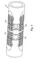
- FIG. 1is perspective view of an open hole anchor in a run-in configuration incorporating slips in accordance with a first embodiment of the present invention
- FIG. 2is an enlarged perspective view one of the slips shown on the open hole anchor of FIG. 1 ;
- FIG. 3is a side view of the slip of FIG. 2 ;
- FIG. 4is a top view of the slip of FIG. 2 ;
- FIG. 5is a side view of the open hole anchor of FIG. 1 in the run-in configuration
- FIG. 6is a side view of the open hole anchor of FIG. 1 in a set configuration
- FIG. 7is an end view of the open hole anchor of FIG. 6 ;
- FIG. 8is a sectional view through line A-A on FIG. 7 ;
- FIG. 9is an enlarged sectional view of the anchor of FIG. 7 taken on the line A-A when anchored in an open hole;
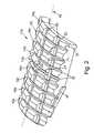
- FIG. 10is a perspective view of an open hole anchor slip in accordance with a second embodiment of the present invention.
- FIG. 11is a cross-sectional side view through line B-B of FIG. 10 .
- FIG. 1there is shown a perspective view of an open hole anchor generally indicated by reference numeral 10 incorporating six slips 12 of which four 12 a to 12 d are visible, in accordance with a first embodiment of the present invention.
- the first slip 12 acan be seen more clearly in FIG. 2 , an enlarged perspective view of one of the slips 12 shown on the open hole anchor 10 of FIG. 1 .
- the slip 12 ahas two rows 14 a , 14 b of penetrating teeth 20 for penetrating, or breaking, a formation surface (not shown) and seven rows 16 a to 16 g of gripping teeth 22 adapted to interact with the formation surface to form an interference.
- Each of the penetrating teeth 20defines a relatively sharp ridge 21 .
- a sharp ridge 21minimises the surface area through which a setting force is applied to the formation, thereby maximising the pressure applied to the formation, with the result that the formation is penetrated by the teeth 20 .
- Each of the gripping teeth 22defines a knurled upper surface 24 with a greater surface area than the penetrating teeth 20 , resulting in a lower pressure being applied to the formation, for a given setting force, than for the penetrating teeth 20 , with the result that friction is established between the formation and the gripping teeth, and the formation is gripped by gripping teeth 22 , rather than penetrated.
- the knurled surface 24forms an interference engagement the formation surface
- the first and second rows of teeth 14 , 16are arranged in parallel rows, transverse to the longitudinal axis 18 of the slip 12 a.
- the slip 12 aalso includes a first guide surface 28 and a second guide surface 30 , the purpose of which will be discussed in connection with FIGS. 5-8 .
- FIG. 3a side view of the slip of FIG. 2 , it can be seen the first and second rows of teeth 14 , 16 extend from an upper surface 26 of the slip 12 a .
- the height of the sharp teeth 20is greater than that of the blunt teeth 22 , with the result, in use, the sharp teeth 20 will penetrate the formation surface before the gripping teeth 22 engage the formation surface.
- the action of the gripping teeth 22 engaging the formationprevents the penetrating teeth 20 from penetrating too far into the formation and possibly causing part of the surface to fracture and break away from the formation.
- the slipalso includes a cam surface 27 , the purpose of which will be discussed in connection with FIGS. 5-8 .
- the rows 14 of penetrating teeth 20are located relatively centrally on the slip 12 a with respect to the longitudinal axis 18 .
- FIG. 5is a side view of the open hole anchor 10 of FIG. 1 in the run-in configuration.
- the anchor 10includes a central housing 40 , a first end housing 42 and a second end housing 44 .
- the slips 12are withdrawn into the anchor 10 so that they do not extend beyond the diameter “X” defined by the anchor 10 . This is the “run-in” configuration.
- FIGS. 6-8various views of the open hole anchor 10 in a set configuration are shown. In the following description, the operation of one of the slips is described. It will be understood the description of FIGS. 6-8 applies equally to the operation of all slips of the open hole anchor.
- first and second end housings 42 , 44have been displaced from the position shown in FIG. 5 , towards the central housing 40 .
- This displacementis achieved by first and second hydraulically controlled pistons (not shown) acting on the respective end surface 43 , 45 of the first and second end housings.
- the displacement of the first and second end housings 42 , 44is trapped by a ratchet device (not shown for clarity), maintaining the slips 12 in the set configuration.
- the slip cam surface 27engages and interacts with a complementary end housing cam surface 47 to urge the slip 27 radially outwards from the anchor 10 .
- the slip guide surfaces 28 , 30are constrained in housing channels 46 , 48 defined by the end housing and the central housing 40 respectively. This arrangement ensures controls movement of each of the six slips 12 towards the formation in a consistent manner.
- the central housing 40includes stops 50 which restrict the movement of the end housings 42 , 44 towards the central housing 40 .
- the maximum achievable in-use expansion of the slips 12 from the anchor 10occurs when the forward surface 52 of the end housing 50 engages one of the stops 50 , that is at the point of maximum displacement of the end housing 42 , 44 towards the central housing 40 .
- the end housings 42 , 44are brought into contact with the central housing 40 , with the stops 50 removed.
- the slips 12can be connected to the housing such that the end and central housing channels 46 , 48 are engaged with the first and second guide surfaces 28 , 30 .
- the slips 12will be withdrawn into the tool 10 by the end and central housing channels 46 , 48 acting on the first and second guide surfaces 28 , 30 .
- the stops 50can be replaced.
- FIG. 9there is shown an enlarged sectional view of the anchor 10 of FIG. 7 taken on the line A-A when anchored in an open hole 60 .
- the open holehas a surface 62
- the anchor 10has been run-in by a mandrel (not shown).
- the slips 12are shown engaged with the surface 62 of the formation 64 .
- the penetrating teeth 20have penetrated the formation surface 62 and the gripping teeth 22 have engaged but not penetrated the formation surface 62 .
- the formation surface 62will not be perfectly smooth, and the degree of interference between teeth 22 and the formation surface 62 will vary, but there will always be some friction between the teeth 22 and the formation surface 62 .
- FIGS. 9 and 10show perspective and cross-sectional side views of an open hole anchor slip, generally indicated by reference numeral 112 , in accordance with a second embodiment of the present invention.
- the slip 112is specifically designed for softer formations than the slip 12 , and is of slightly greater length than slip 12 to spread the load over a greater area.
- the slips 122can be arranged differently to the arrangement shown in the tool 10 of FIG. 1 to further spread the applied stresses to different parts of the formation.
- the tool 10 of FIG. 1has two sets of three slips 12 arranged in pairs spaced equally around the tool. In the alternative arrangement the second set of slips could be offset 60° from the first set.
- the slip 112has three penetrating teeth 120 A- 120 C for penetrating, or breaking, a formation surface (not shown), and fourteen rows 122 of gripping teeth adapted to interact with the formation surface to form an interference. For clarity, only three of the rows “ 122 A”, “ 122 B” and “ 122 C” are indicated.
- each penetrating tooth 120does not comprise a number of discrete teeth, rather a single tooth.
- the absence of the axial grooves 90 between the teeth, which divided the teeth of FIG. 2assists in preventing the slip 122 , in use, from digging into the formation when attached to a tool, as the tool is lifted by the slips 112 into position.
- the inclusion of a chamfer 192 on slip 112also assists in preventing the slip 112 from digging into the formation as the tool is lifted.
- the radial groove 194 between each adjacent tooth 120 , 122is shallower than the corresponding radial grooves 94 of the slip 12 (shown in FIG. 2 ).
- the grooves 194 , 94fill with crumbled formation, and the shallower the groove 194 , 94 , the quicker it will fill with crumbled formation, with the result that the maximum contact area between the formation and the slip 112 is achieved sooner than is the case with a deeper groove.
- the slip 112includes three guide surface, 180 , 182 and 184 for expanding the slip 112 into formation engagement which are designed to spread the stresses generated by axial loading.
- any suitable means of setting the slipscould be employed including setting hydraulically with swab cups on a wash pipe below a running tool, or by a hydraulically triggered hydrostatic chamber. Any suitable industry standard setting tool can be used to set the slips.
Landscapes
- Life Sciences & Earth Sciences (AREA)
- Engineering & Computer Science (AREA)
- Geology (AREA)
- Mining & Mineral Resources (AREA)
- Physics & Mathematics (AREA)
- Environmental & Geological Engineering (AREA)
- Fluid Mechanics (AREA)
- General Life Sciences & Earth Sciences (AREA)
- Geochemistry & Mineralogy (AREA)
- Dowels (AREA)
- Piles And Underground Anchors (AREA)
Abstract
Description
Claims (30)
Applications Claiming Priority (4)
| Application Number | Priority Date | Filing Date | Title |
|---|---|---|---|
| GBGB0504471.4AGB0504471D0 (en) | 2005-03-04 | 2005-03-04 | Improved well bore anchors |
| GB0504471.4 | 2005-03-04 | ||
| PCT/GB2005/003871WO2006092545A1 (en) | 2005-03-04 | 2005-10-07 | Improved well bore anchors |
| GBPCT/GB2005/003871 | 2005-10-07 |
Publications (2)
| Publication Number | Publication Date |
|---|---|
| US20090014173A1 US20090014173A1 (en) | 2009-01-15 |
| US7690424B2true US7690424B2 (en) | 2010-04-06 |
Family
ID=34451786
Family Applications (1)
| Application Number | Title | Priority Date | Filing Date |
|---|---|---|---|
| US11/816,421Expired - LifetimeUS7690424B2 (en) | 2005-03-04 | 2005-10-07 | Well bore anchors |
Country Status (7)
| Country | Link |
|---|---|
| US (1) | US7690424B2 (en) |
| AU (1) | AU2005328564B2 (en) |
| BR (1) | BRPI0519978B1 (en) |
| CA (1) | CA2644667C (en) |
| GB (2) | GB0504471D0 (en) |
| NO (1) | NO341052B1 (en) |
| WO (1) | WO2006092545A1 (en) |
Cited By (14)
| Publication number | Priority date | Publication date | Assignee | Title |
|---|---|---|---|---|
| US20070261863A1 (en)* | 2004-06-11 | 2007-11-15 | Iain Macleod | Sealing system |
| US20080156500A1 (en)* | 2005-04-09 | 2008-07-03 | Iain Macleod | Packer |
| US20090114401A1 (en)* | 2004-10-29 | 2009-05-07 | Daniel Purkis | Plug |
| US20090308592A1 (en)* | 2006-03-23 | 2009-12-17 | Lee Mercer | Packer |
| US20100170681A1 (en)* | 2006-11-17 | 2010-07-08 | Petrowell Limited | Tree plug |
| US20110005779A1 (en)* | 2009-07-09 | 2011-01-13 | Weatherford/Lamb, Inc. | Composite downhole tool with reduced slip volume |
| US20110005776A1 (en)* | 2008-03-18 | 2011-01-13 | Petrowell Limited | Improved centraliser |
| US20110042106A1 (en)* | 2007-12-03 | 2011-02-24 | Petrowell Ltd. | Centraliser |
| US20110100648A1 (en)* | 2007-06-20 | 2011-05-05 | Petrowell Ltd. | Improved activation device |
| US20110114332A1 (en)* | 2008-02-21 | 2011-05-19 | Petrowell Limited | Tubing section |
| US20110127768A1 (en)* | 2008-03-29 | 2011-06-02 | Petrowell Limited | Improved tubing section coupling |
| US9157288B2 (en) | 2012-07-19 | 2015-10-13 | General Plastics & Composites, L.P. | Downhole tool system and method related thereto |
| WO2016081756A1 (en) | 2014-11-19 | 2016-05-26 | Weatherford Technology Holdings, Llc | Downhole tool having slips set by stacked rings |
| US9890604B2 (en) | 2014-04-04 | 2018-02-13 | Owen Oil Tools Lp | Devices and related methods for actuating wellbore tools with a pressurized gas |
Families Citing this family (20)
| Publication number | Priority date | Publication date | Assignee | Title |
|---|---|---|---|---|
| US7614449B2 (en)* | 2007-08-08 | 2009-11-10 | Baker Hughes Incorporated | Tangentially-loaded high-load retrievable slip system |
| AR079760A1 (en) | 2010-12-28 | 2012-02-15 | Texproil S R L | RECOVERY HYDRAULIC PACKAGING DEVICE USED IN WATER, GAS AND PETROLEUM WELLS OR SIMILAR FLUIDS |
| US9416608B2 (en) | 2013-07-17 | 2016-08-16 | Baker Hughes Incorporated | Slip, tangential slip system having slip, and method thereof |
| GB201418128D0 (en) | 2014-10-14 | 2014-11-26 | Weatherford Uk Ltd | Downhole anchor |
| GB2604814B (en) | 2020-01-17 | 2024-10-09 | Halliburton Energy Services Inc | Heaters to accelerate setting of expandable metal |
| GB2605062B (en) | 2020-01-17 | 2024-09-25 | Halliburton Energy Services Inc | Voltage to accelerate/decelerate expandable metal |
| GB2592635B (en)* | 2020-03-05 | 2022-08-24 | Ardyne Holdings Ltd | Improvements in or relating to wellbore operations |
| NO20230030A1 (en) | 2020-08-13 | 2023-01-12 | Halliburton Energy Services Inc | Expandable metal displacement plug |
| GB2612234B (en)* | 2020-10-02 | 2024-07-10 | Halliburton Energy Services Inc | Open-hole pressure tight multilateral junction |
| MX2023009992A (en) | 2021-04-12 | 2023-09-06 | Halliburton Energy Services Inc | Expandable metal as backup for elastomeric elements. |
| US12326060B2 (en) | 2021-05-21 | 2025-06-10 | Halliburton Energy Services, Inc. | Wellbore anchor including one or more activation chambers |
| NO20231087A1 (en) | 2021-05-28 | 2023-10-13 | Halliburton Energy Services Inc | Individual separate chunks of expandable metal |
| PL446571A1 (en) | 2021-05-28 | 2024-05-20 | Halliburton Energy Services, Inc. | Quick-setting, expandable metal |
| US12421824B2 (en) | 2021-05-29 | 2025-09-23 | Halliburton Energy Services, Inc. | Using expandable metal as an alternate to existing metal to metal seals |
| WO2022255988A1 (en) | 2021-06-01 | 2022-12-08 | Halliburton Energy Services, Inc. | Expanding metal used in forming support structures |
| US12378832B2 (en)* | 2021-10-05 | 2025-08-05 | Halliburton Energy Services, Inc. | Expandable metal sealing/anchoring tool |
| US12305459B2 (en) | 2022-06-15 | 2025-05-20 | Halliburton Energy Services, Inc. | Sealing/anchoring tool employing an expandable metal circlet |
| US12385340B2 (en) | 2022-12-05 | 2025-08-12 | Halliburton Energy Services, Inc. | Reduced backlash sealing/anchoring assembly |
| US12252946B2 (en) | 2023-07-06 | 2025-03-18 | Halliburton Energy Services, Inc. | Wellbore tubular anchor sub and seal for modular completion interface |
| WO2025158172A1 (en)* | 2024-01-22 | 2025-07-31 | Khodayar Behnam | Single-trip modular whipstock with the potential of simultaneous use in case hole wells or different open hole wells |
Citations (11)
| Publication number | Priority date | Publication date | Assignee | Title |
|---|---|---|---|---|
| US2546377A (en)* | 1942-01-20 | 1951-03-27 | Lane Wells Co | Bridging plug |
| GB755082A (en) | 1953-10-12 | 1956-08-15 | Baker Oil Tools Inc | Subsurface well tools |
| US3066738A (en)* | 1958-09-08 | 1962-12-04 | Baker Oil Tools Inc | Well packer and setting device therefor |
| US3167127A (en)* | 1961-04-04 | 1965-01-26 | Otis Eng Co | Dual well packer |
| US3167128A (en) | 1962-04-24 | 1965-01-26 | Wayne N Sutliff | Selective formation zone anchor |
| US3623551A (en)* | 1970-01-02 | 1971-11-30 | Schlumberger Technology Corp | Anchoring apparatus for a well packer |
| US3889750A (en) | 1974-07-17 | 1975-06-17 | Schlumberger Technology Corp | Setting and releasing apparatus for sidewall anchor |
| US4317485A (en) | 1980-05-23 | 1982-03-02 | Baker International Corporation | Pump catcher apparatus |
| US4917187A (en) | 1989-01-23 | 1990-04-17 | Baker Hughes Incorporated | Method and apparatus for hydraulically firing a perforating gun below a set packer |
| GB2245624A (en) | 1990-06-29 | 1992-01-08 | Baker Hughes Inc | Liner hanger assembly |
| US6062309A (en) | 1997-07-11 | 2000-05-16 | Variperm Limited | Torque roller anchor |
Family Cites Families (1)
| Publication number | Priority date | Publication date | Assignee | Title |
|---|---|---|---|---|
| US3460616A (en)* | 1967-07-26 | 1969-08-12 | Dresser Ind | Retrievable packer |
- 2005
- 2005-03-04GBGBGB0504471.4Apatent/GB0504471D0/ennot_activeCeased
- 2005-10-07WOPCT/GB2005/003871patent/WO2006092545A1/enactiveApplication Filing
- 2005-10-07USUS11/816,421patent/US7690424B2/ennot_activeExpired - Lifetime
- 2005-10-07AUAU2005328564Apatent/AU2005328564B2/ennot_activeExpired
- 2005-10-07BRBRPI0519978Apatent/BRPI0519978B1/enactiveIP Right Grant
- 2005-10-07CACA2644667Apatent/CA2644667C/ennot_activeExpired - Lifetime
- 2005-11-04GBGB0520425Apatent/GB2423779B/enactiveActive
- 2007
- 2007-08-27NONO20074351Apatent/NO341052B1/enunknown
Patent Citations (11)
| Publication number | Priority date | Publication date | Assignee | Title |
|---|---|---|---|---|
| US2546377A (en)* | 1942-01-20 | 1951-03-27 | Lane Wells Co | Bridging plug |
| GB755082A (en) | 1953-10-12 | 1956-08-15 | Baker Oil Tools Inc | Subsurface well tools |
| US3066738A (en)* | 1958-09-08 | 1962-12-04 | Baker Oil Tools Inc | Well packer and setting device therefor |
| US3167127A (en)* | 1961-04-04 | 1965-01-26 | Otis Eng Co | Dual well packer |
| US3167128A (en) | 1962-04-24 | 1965-01-26 | Wayne N Sutliff | Selective formation zone anchor |
| US3623551A (en)* | 1970-01-02 | 1971-11-30 | Schlumberger Technology Corp | Anchoring apparatus for a well packer |
| US3889750A (en) | 1974-07-17 | 1975-06-17 | Schlumberger Technology Corp | Setting and releasing apparatus for sidewall anchor |
| US4317485A (en) | 1980-05-23 | 1982-03-02 | Baker International Corporation | Pump catcher apparatus |
| US4917187A (en) | 1989-01-23 | 1990-04-17 | Baker Hughes Incorporated | Method and apparatus for hydraulically firing a perforating gun below a set packer |
| GB2245624A (en) | 1990-06-29 | 1992-01-08 | Baker Hughes Inc | Liner hanger assembly |
| US6062309A (en) | 1997-07-11 | 2000-05-16 | Variperm Limited | Torque roller anchor |
Non-Patent Citations (3)
| Title |
|---|
| International Search Report. |
| UKIPO Office Action in priority case examination. |
| Written Opinion of the International Searching Authority. |
Cited By (27)
| Publication number | Priority date | Publication date | Assignee | Title |
|---|---|---|---|---|
| US20070261863A1 (en)* | 2004-06-11 | 2007-11-15 | Iain Macleod | Sealing system |
| US8678099B2 (en) | 2004-06-11 | 2014-03-25 | Petrowell Limited | Sealing system |
| US8490691B2 (en) | 2004-10-29 | 2013-07-23 | Petrowell Limited | Plug |
| US20090114401A1 (en)* | 2004-10-29 | 2009-05-07 | Daniel Purkis | Plug |
| US8973666B2 (en) | 2004-10-29 | 2015-03-10 | Petrowell Limited | Running adapter |
| US20080156500A1 (en)* | 2005-04-09 | 2008-07-03 | Iain Macleod | Packer |
| US9194213B2 (en) | 2005-04-09 | 2015-11-24 | Petrowell Limited | Packer |
| US20090308592A1 (en)* | 2006-03-23 | 2009-12-17 | Lee Mercer | Packer |
| US9562411B2 (en) | 2006-03-23 | 2017-02-07 | Petrowell Limited | Packer |
| US8651178B2 (en) | 2006-03-23 | 2014-02-18 | Petrowell Limited | Packer |
| US8839872B2 (en) | 2006-11-17 | 2014-09-23 | Petrowell Limited | Tree plug |
| US20100170681A1 (en)* | 2006-11-17 | 2010-07-08 | Petrowell Limited | Tree plug |
| US20110057395A1 (en)* | 2006-11-17 | 2011-03-10 | Petrowell Ltd. | Seal element |
| US20110100648A1 (en)* | 2007-06-20 | 2011-05-05 | Petrowell Ltd. | Improved activation device |
| US8689864B2 (en) | 2007-06-20 | 2014-04-08 | Petrowell Limited | Activation device |
| US8555964B2 (en) | 2007-12-03 | 2013-10-15 | Petrowell Limited | Centraliser |
| US20110042106A1 (en)* | 2007-12-03 | 2011-02-24 | Petrowell Ltd. | Centraliser |
| US20110114332A1 (en)* | 2008-02-21 | 2011-05-19 | Petrowell Limited | Tubing section |
| US9702231B2 (en) | 2008-02-21 | 2017-07-11 | Petrowell Limited | Tubing section |
| US20110005776A1 (en)* | 2008-03-18 | 2011-01-13 | Petrowell Limited | Improved centraliser |
| US8820417B2 (en) | 2008-03-18 | 2014-09-02 | Petrowell Limited | Centraliser |
| US9133968B2 (en) | 2008-03-29 | 2015-09-15 | Petrowell Limited | Tubing section coupling |
| US20110127768A1 (en)* | 2008-03-29 | 2011-06-02 | Petrowell Limited | Improved tubing section coupling |
| US20110005779A1 (en)* | 2009-07-09 | 2011-01-13 | Weatherford/Lamb, Inc. | Composite downhole tool with reduced slip volume |
| US9157288B2 (en) | 2012-07-19 | 2015-10-13 | General Plastics & Composites, L.P. | Downhole tool system and method related thereto |
| US9890604B2 (en) | 2014-04-04 | 2018-02-13 | Owen Oil Tools Lp | Devices and related methods for actuating wellbore tools with a pressurized gas |
| WO2016081756A1 (en) | 2014-11-19 | 2016-05-26 | Weatherford Technology Holdings, Llc | Downhole tool having slips set by stacked rings |
Also Published As
| Publication number | Publication date |
|---|---|
| CA2644667A1 (en) | 2006-09-08 |
| CA2644667C (en) | 2013-09-17 |
| AU2005328564A1 (en) | 2006-09-08 |
| BRPI0519978A2 (en) | 2009-08-18 |
| WO2006092545A1 (en) | 2006-09-08 |
| GB0504471D0 (en) | 2005-04-13 |
| NO341052B1 (en) | 2017-08-14 |
| US20090014173A1 (en) | 2009-01-15 |
| NO20074351L (en) | 2007-11-19 |
| BRPI0519978B1 (en) | 2017-04-18 |
| AU2005328564B2 (en) | 2012-03-08 |
| GB2423779A (en) | 2006-09-06 |
| GB2423779B (en) | 2008-03-05 |
| GB0520425D0 (en) | 2005-11-16 |
Similar Documents
| Publication | Publication Date | Title |
|---|---|---|
| US7690424B2 (en) | Well bore anchors | |
| CA2449919C (en) | Expansion set liner hanger and method of setting same | |
| EP1172521B1 (en) | Downhole packer with caged ball valve | |
| EP3592940B1 (en) | Downhole anchor mechanism | |
| CA2448691C (en) | Expandable tubular having improved polished bore receptacle protection | |
| EP1052369A2 (en) | Downhole packing apparatus | |
| US9617823B2 (en) | Axially compressed and radially pressed seal | |
| CA3030281C (en) | Wellbore isolation device with telescoping setting system | |
| NO336616B1 (en) | Expandable well tool for use in a wellbore and method for running a first tube in a wellbore | |
| GB2424012A (en) | Anchor for a whipstock | |
| US11802454B2 (en) | Downhole anchor | |
| AU2006220393B2 (en) | Lock ring for pipe slip pick-up ring |
Legal Events
| Date | Code | Title | Description |
|---|---|---|---|
| AS | Assignment | Owner name:PETROWELL LIMITED, UNITED KINGDOM Free format text:ASSIGNMENT OF ASSIGNORS INTEREST;ASSIGNORS:MCLEOD, IAIN;REID, STEVE;REEL/FRAME:020286/0331 Effective date:20071204 Owner name:PETROWELL LIMITED,UNITED KINGDOM Free format text:ASSIGNMENT OF ASSIGNORS INTEREST;ASSIGNORS:MCLEOD, IAIN;REID, STEVE;REEL/FRAME:020286/0331 Effective date:20071204 | |
| STCF | Information on status: patent grant | Free format text:PATENTED CASE | |
| FEPP | Fee payment procedure | Free format text:PAT HOLDER NO LONGER CLAIMS SMALL ENTITY STATUS, ENTITY STATUS SET TO UNDISCOUNTED (ORIGINAL EVENT CODE: STOL); ENTITY STATUS OF PATENT OWNER: LARGE ENTITY | |
| REFU | Refund | Free format text:REFUND - SURCHARGE, PETITION TO ACCEPT PYMT AFTER EXP, UNINTENTIONAL (ORIGINAL EVENT CODE: R2551); ENTITY STATUS OF PATENT OWNER: LARGE ENTITY | |
| FPAY | Fee payment | Year of fee payment:4 | |
| AS | Assignment | Owner name:WEATHERFORD TECHNOLOGY HOLDINGS, LLC, TEXAS Free format text:ASSIGNMENT OF ASSIGNORS INTEREST;ASSIGNOR:PETROWELL, LTD.;REEL/FRAME:043506/0292 Effective date:20170629 | |
| AS | Assignment | Owner name:WEATHERFORD TECHNOLOGY HOLDINGS, LLC, TEXAS Free format text:ASSIGNMENT OF ASSIGNORS INTEREST;ASSIGNOR:PETROWELL LTD.;REEL/FRAME:043722/0898 Effective date:20170629 | |
| MAFP | Maintenance fee payment | Free format text:PAYMENT OF MAINTENANCE FEE, 8TH YEAR, LARGE ENTITY (ORIGINAL EVENT CODE: M1552) Year of fee payment:8 | |
| AS | Assignment | Owner name:WELLS FARGO BANK NATIONAL ASSOCIATION AS AGENT, TEXAS Free format text:SECURITY INTEREST;ASSIGNORS:WEATHERFORD TECHNOLOGY HOLDINGS LLC;WEATHERFORD NETHERLANDS B.V.;WEATHERFORD NORGE AS;AND OTHERS;REEL/FRAME:051891/0089 Effective date:20191213 | |
| AS | Assignment | Owner name:DEUTSCHE BANK TRUST COMPANY AMERICAS, AS ADMINISTR Free format text:SECURITY INTEREST;ASSIGNORS:WEATHERFORD TECHNOLOGY HOLDINGS, LLC;WEATHERFORD NETHERLANDS B.V.;WEATHERFORD NORGE AS;AND OTHERS;REEL/FRAME:051419/0140 Effective date:20191213 Owner name:DEUTSCHE BANK TRUST COMPANY AMERICAS, AS ADMINISTRATIVE AGENT, NEW YORK Free format text:SECURITY INTEREST;ASSIGNORS:WEATHERFORD TECHNOLOGY HOLDINGS, LLC;WEATHERFORD NETHERLANDS B.V.;WEATHERFORD NORGE AS;AND OTHERS;REEL/FRAME:051419/0140 Effective date:20191213 | |
| AS | Assignment | Owner name:WEATHERFORD CANADA LTD., TEXAS Free format text:RELEASE BY SECURED PARTY;ASSIGNOR:WELLS FARGO BANK, NATIONAL ASSOCIATION;REEL/FRAME:053838/0323 Effective date:20200828 Owner name:WEATHERFORD NETHERLANDS B.V., TEXAS Free format text:RELEASE BY SECURED PARTY;ASSIGNOR:WELLS FARGO BANK, NATIONAL ASSOCIATION;REEL/FRAME:053838/0323 Effective date:20200828 Owner name:WEATHERFORD NORGE AS, TEXAS Free format text:RELEASE BY SECURED PARTY;ASSIGNOR:WELLS FARGO BANK, NATIONAL ASSOCIATION;REEL/FRAME:053838/0323 Effective date:20200828 Owner name:WEATHERFORD TECHNOLOGY HOLDINGS, LLC, TEXAS Free format text:RELEASE BY SECURED PARTY;ASSIGNOR:WELLS FARGO BANK, NATIONAL ASSOCIATION;REEL/FRAME:053838/0323 Effective date:20200828 Owner name:PRECISION ENERGY SERVICES, INC., TEXAS Free format text:RELEASE BY SECURED PARTY;ASSIGNOR:WELLS FARGO BANK, NATIONAL ASSOCIATION;REEL/FRAME:053838/0323 Effective date:20200828 Owner name:WEATHERFORD SWITZERLAND TRADING AND DEVELOPMENT GMBH, TEXAS Free format text:RELEASE BY SECURED PARTY;ASSIGNOR:WELLS FARGO BANK, NATIONAL ASSOCIATION;REEL/FRAME:053838/0323 Effective date:20200828 Owner name:HIGH PRESSURE INTEGRITY, INC., TEXAS Free format text:RELEASE BY SECURED PARTY;ASSIGNOR:WELLS FARGO BANK, NATIONAL ASSOCIATION;REEL/FRAME:053838/0323 Effective date:20200828 Owner name:WEATHERFORD U.K. LIMITED, TEXAS Free format text:RELEASE BY SECURED PARTY;ASSIGNOR:WELLS FARGO BANK, NATIONAL ASSOCIATION;REEL/FRAME:053838/0323 Effective date:20200828 Owner name:PRECISION ENERGY SERVICES ULC, TEXAS Free format text:RELEASE BY SECURED PARTY;ASSIGNOR:WELLS FARGO BANK, NATIONAL ASSOCIATION;REEL/FRAME:053838/0323 Effective date:20200828 Owner name:WILMINGTON TRUST, NATIONAL ASSOCIATION, MINNESOTA Free format text:SECURITY INTEREST;ASSIGNORS:WEATHERFORD TECHNOLOGY HOLDINGS, LLC;WEATHERFORD NETHERLANDS B.V.;WEATHERFORD NORGE AS;AND OTHERS;REEL/FRAME:054288/0302 Effective date:20200828 | |
| AS | Assignment | Owner name:WILMINGTON TRUST, NATIONAL ASSOCIATION, MINNESOTA Free format text:SECURITY INTEREST;ASSIGNORS:WEATHERFORD TECHNOLOGY HOLDINGS, LLC;WEATHERFORD NETHERLANDS B.V.;WEATHERFORD NORGE AS;AND OTHERS;REEL/FRAME:057683/0706 Effective date:20210930 Owner name:WEATHERFORD U.K. LIMITED, TEXAS Free format text:RELEASE BY SECURED PARTY;ASSIGNOR:WILMINGTON TRUST, NATIONAL ASSOCIATION;REEL/FRAME:057683/0423 Effective date:20210930 Owner name:PRECISION ENERGY SERVICES ULC, TEXAS Free format text:RELEASE BY SECURED PARTY;ASSIGNOR:WILMINGTON TRUST, NATIONAL ASSOCIATION;REEL/FRAME:057683/0423 Effective date:20210930 Owner name:WEATHERFORD SWITZERLAND TRADING AND DEVELOPMENT GMBH, TEXAS Free format text:RELEASE BY SECURED PARTY;ASSIGNOR:WILMINGTON TRUST, NATIONAL ASSOCIATION;REEL/FRAME:057683/0423 Effective date:20210930 Owner name:WEATHERFORD CANADA LTD, TEXAS Free format text:RELEASE BY SECURED PARTY;ASSIGNOR:WILMINGTON TRUST, NATIONAL ASSOCIATION;REEL/FRAME:057683/0423 Effective date:20210930 Owner name:PRECISION ENERGY SERVICES, INC., TEXAS Free format text:RELEASE BY SECURED PARTY;ASSIGNOR:WILMINGTON TRUST, NATIONAL ASSOCIATION;REEL/FRAME:057683/0423 Effective date:20210930 Owner name:HIGH PRESSURE INTEGRITY, INC., TEXAS Free format text:RELEASE BY SECURED PARTY;ASSIGNOR:WILMINGTON TRUST, NATIONAL ASSOCIATION;REEL/FRAME:057683/0423 Effective date:20210930 Owner name:WEATHERFORD NORGE AS, TEXAS Free format text:RELEASE BY SECURED PARTY;ASSIGNOR:WILMINGTON TRUST, NATIONAL ASSOCIATION;REEL/FRAME:057683/0423 Effective date:20210930 Owner name:WEATHERFORD NETHERLANDS B.V., TEXAS Free format text:RELEASE BY SECURED PARTY;ASSIGNOR:WILMINGTON TRUST, NATIONAL ASSOCIATION;REEL/FRAME:057683/0423 Effective date:20210930 Owner name:WEATHERFORD TECHNOLOGY HOLDINGS, LLC, TEXAS Free format text:RELEASE BY SECURED PARTY;ASSIGNOR:WILMINGTON TRUST, NATIONAL ASSOCIATION;REEL/FRAME:057683/0423 Effective date:20210930 | |
| MAFP | Maintenance fee payment | Free format text:PAYMENT OF MAINTENANCE FEE, 12TH YEAR, LARGE ENTITY (ORIGINAL EVENT CODE: M1553); ENTITY STATUS OF PATENT OWNER: LARGE ENTITY Year of fee payment:12 | |
| AS | Assignment | Owner name:WELLS FARGO BANK, NATIONAL ASSOCIATION, NORTH CAROLINA Free format text:PATENT SECURITY INTEREST ASSIGNMENT AGREEMENT;ASSIGNOR:DEUTSCHE BANK TRUST COMPANY AMERICAS;REEL/FRAME:063470/0629 Effective date:20230131 |