US7690414B2 - Motorized window shade - Google Patents
Motorized window shadeDownload PDFInfo
- Publication number
- US7690414B2 US7690414B2US11/645,981US64598106AUS7690414B2US 7690414 B2US7690414 B2US 7690414B2US 64598106 AUS64598106 AUS 64598106AUS 7690414 B2US7690414 B2US 7690414B2
- Authority
- US
- United States
- Prior art keywords
- window
- shade
- rotatable shaft
- motor
- housing
- Prior art date
- Legal status (The legal status is an assumption and is not a legal conclusion. Google has not performed a legal analysis and makes no representation as to the accuracy of the status listed.)
- Expired - Fee Related, expires
Links
- 230000007246mechanismEffects0.000claimsabstractdescription31
- 230000002441reversible effectEffects0.000claimsabstractdescription23
- 230000008878couplingEffects0.000claimsdescription37
- 238000010168coupling processMethods0.000claimsdescription37
- 238000005859coupling reactionMethods0.000claimsdescription37
- 230000004044responseEffects0.000claimsdescription12
- 230000000712assemblyEffects0.000claimsdescription8
- 238000000429assemblyMethods0.000claimsdescription8
- 230000005540biological transmissionEffects0.000claims6
- WABPQHHGFIMREM-OIOBTWANSA-Nlead-204Chemical compound[204Pb]WABPQHHGFIMREM-OIOBTWANSA-N0.000description3
- 238000010586diagramMethods0.000description2
- 230000004048modificationEffects0.000description2
- 238000012986modificationMethods0.000description2
- 230000007257malfunctionEffects0.000description1
- 238000004519manufacturing processMethods0.000description1
- 230000002093peripheral effectEffects0.000description1
- 230000009467reductionEffects0.000description1
- 210000003813thumbAnatomy0.000description1
Images


Classifications
- B—PERFORMING OPERATIONS; TRANSPORTING
- B64—AIRCRAFT; AVIATION; COSMONAUTICS
- B64C—AEROPLANES; HELICOPTERS
- B64C1/00—Fuselages; Constructional features common to fuselages, wings, stabilising surfaces or the like
- B64C1/14—Windows; Doors; Hatch covers or access panels; Surrounding frame structures; Canopies; Windscreens accessories therefor, e.g. pressure sensors, water deflectors, hinges, seals, handles, latches, windscreen wipers
- B64C1/1476—Canopies; Windscreens or similar transparent elements
- B64C1/1484—Windows
- B—PERFORMING OPERATIONS; TRANSPORTING
- B60—VEHICLES IN GENERAL
- B60J—WINDOWS, WINDSCREENS, NON-FIXED ROOFS, DOORS, OR SIMILAR DEVICES FOR VEHICLES; REMOVABLE EXTERNAL PROTECTIVE COVERINGS SPECIALLY ADAPTED FOR VEHICLES
- B60J1/00—Windows; Windscreens; Accessories therefor
- B60J1/20—Accessories, e.g. wind deflectors, blinds
- B60J1/2011—Blinds; curtains or screens reducing heat or light intensity
- B60J1/2013—Roller blinds
- B60J1/2019—Roller blinds powered, e.g. by electric, hydraulic or pneumatic actuators
- B60J1/2025—Roller blinds powered, e.g. by electric, hydraulic or pneumatic actuators with flexible actuating elements connected to the draw bar for pulling only, e.g. cords, wires or cables
- B—PERFORMING OPERATIONS; TRANSPORTING
- B60—VEHICLES IN GENERAL
- B60J—WINDOWS, WINDSCREENS, NON-FIXED ROOFS, DOORS, OR SIMILAR DEVICES FOR VEHICLES; REMOVABLE EXTERNAL PROTECTIVE COVERINGS SPECIALLY ADAPTED FOR VEHICLES
- B60J1/00—Windows; Windscreens; Accessories therefor
- B60J1/20—Accessories, e.g. wind deflectors, blinds
- B60J1/2011—Blinds; curtains or screens reducing heat or light intensity
- B60J1/2091—Foldable sunscreens
- E—FIXED CONSTRUCTIONS
- E06—DOORS, WINDOWS, SHUTTERS, OR ROLLER BLINDS IN GENERAL; LADDERS
- E06B—FIXED OR MOVABLE CLOSURES FOR OPENINGS IN BUILDINGS, VEHICLES, FENCES OR LIKE ENCLOSURES IN GENERAL, e.g. DOORS, WINDOWS, BLINDS, GATES
- E06B9/00—Screening or protective devices for wall or similar openings, with or without operating or securing mechanisms; Closures of similar construction
- E06B9/24—Screens or other constructions affording protection against light, especially against sunshine; Similar screens for privacy or appearance; Slat blinds
- E06B9/26—Lamellar or like blinds, e.g. venetian blinds
- E06B9/262—Lamellar or like blinds, e.g. venetian blinds with flexibly-interconnected horizontal or vertical strips; Concertina blinds, i.e. upwardly folding flexible screens
- E06B2009/2625—Pleated screens, e.g. concertina- or accordion-like
- E—FIXED CONSTRUCTIONS
- E06—DOORS, WINDOWS, SHUTTERS, OR ROLLER BLINDS IN GENERAL; LADDERS
- E06B—FIXED OR MOVABLE CLOSURES FOR OPENINGS IN BUILDINGS, VEHICLES, FENCES OR LIKE ENCLOSURES IN GENERAL, e.g. DOORS, WINDOWS, BLINDS, GATES
- E06B9/00—Screening or protective devices for wall or similar openings, with or without operating or securing mechanisms; Closures of similar construction
- E06B9/24—Screens or other constructions affording protection against light, especially against sunshine; Similar screens for privacy or appearance; Slat blinds
- E06B9/26—Lamellar or like blinds, e.g. venetian blinds
- E06B9/262—Lamellar or like blinds, e.g. venetian blinds with flexibly-interconnected horizontal or vertical strips; Concertina blinds, i.e. upwardly folding flexible screens
Definitions
- the inventionrelates generally to a motorized window shade and is disclosed in connection with a motorized window shade mechanism adapted for use in windows of multi-passenger vehicles, such as an airplane.
- Still another shade mechanisminvolves a motor attached to a lower bar or rail of a shade.
- the motormoves along with the shade as the shade is extended and retracted. See U.S. Pat. No. 4,807,686.
- this shade mechanismalso utilizes numerous components, which increases the cost of production and reduces the reliability of operation.
- a further shortcoming of at least some of the above-mentioned designsis too much bulk and weight.
- the space available in an aircraft window within which the entire window shade assembly must fitis quite restricted. Also, reduction of weight is of particularly high importance in an aircraft environment.
- U.S. Pat. No. 6,186,211discloses a motorized window shade assembly for operating a window shade having a rail attached to one end of the shade to extend and compress the shade with movement of the rail.
- the motorized window shade assemblyincludes a shell having two sidewalls, and a rail extending between the two sidewalls of the shell.
- the sidewallshave respective opposed inner surfaces with a channel therein, shoulders adjacent and perpendicular to the inner surfaces, respectively, and a traction surface on each of the shoulders.
- An axleis rotatingly coupled to the rail and has a traction wheel coupled to each end thereof. Opposite tips of the axle ride within the channels in the sidewalls, and the traction wheels engage the traction surface.
- a motoris attached to the rail and is drivingly coupled to the axle.
- One object of the present inventionis to provide an improved motorized window shade mechanism.
- Another object of the present inventionis to provide a motorized window shade mechanism that can be of a size small enough to suitably fit within the restricted space available in windows used on aircraft.
- the mechanismcomprises motorized rotational motion generating means, disposed proximate to the fixed end of the window shade, for generating rotational motion.
- First converting meansconverts the rotational motion of the rotational motion generating means to linear motion between the retracted position and the extended position.
- Second converting meansconverts the linear motion of the first converting means to rotational motion.
- Third converting meansconverts the rotational motion of the second converting means to linear motion between the retracted position and the extended position.
- Meansis provided for coupling the free end of the window shade to the first and third converting means so that the window shade is operated with operation of the rotational motion generating means to move the free end of the window shade between the retracted position and the extended position.
- Another aspect of the present inventionis directed to a motorized mechanism for operating a window shade in relation to a window secured in a shell having a first end and a second end, and a first side wall and a second sidewall, the first and second sidewalls extending between the first and second ends.
- the window shadeincludes a fixed end, secured proximate to the first end of the shell, and a free end that is movable between the first and second ends of the shell from a retracted position at the first end where the passage of light through the window is unobstructed, and an extended position at the second end where the passage of light through the window is obstructed.
- the motorized mechanismcomprises a motor secured proximate to the fixed end of the window shade, and a rotatable shaft comprising a first end and a second end, the rotatable shaft being rotatably secured at the second end of the shell and disposed between the first and second sidewalls.
- Rotation coupling meansextends along the first sidewall between the reversible motor and the first end of the rotatable shaft to drive the rotatable shaft with operation of the reversible motor.
- First traversing meansis coupled to the rotation coupling means for moving along the first sidewall between the first and second ends of the shell as the rotation coupling means drives the rotatable shaft with operation of the reversible motor.
- Second traversing meansis coupled to the driven means for moving along the second sidewall between the first and second ends of the shell in conjunction with the first traversing means as the rotation coupling means drives the rotatable shaft with operation of the reversible motor.
- Means for connecting the free end of the window shade between the first and second traversing meansis provided so that the window shade is operated with operation of the reversible motor.
- Yet another aspect of the inventionis directed to a window comprising a housing defining a first opening and a second opening, and comprising a first end, a second end, a first sidewall, and a second sidewall, the first and second sidewalls extending between the first end and the second end.
- a first window shadecomprises a fixed end and a free end, the first window shade being disposed inside the housing, the fixed end extending between the first and second sidewalls and being fixed proximate to the first end of the housing, the free end extending between the first and second sidewalls and being movable along the first and second sidewalls between a retracted position, where the passage of light through the first and second openings is unobstructed by said first window shade, and an extended position, where the passage of light through the first and second openings is obstructed by said first window shade.
- a second window shadecomprises a fixed end and a free end, the second window shade being disposed inside the housing, the fixed end extending between the first and second sidewalls and being fixed proximate to the first end of the housing, the free end extending between the first and second sidewalls and being movable along the first and second sidewalls between a retracted position, where the passage of light through the first and second openings is unobstructed by the second window shade, and an extended position, where the passage of light through the first and second openings is obstructed by the second window shade.
- a first motoris secured proximate to the first end of the housing.
- a second motoris secured proximate to the first end of the housing.
- a first rotation meansis rotatably secured proximate to the first end of the housing.
- a second rotation meansis rotatably secured proximate to the first end of the housing.
- a first rotatable shaftcomprises a first end and a second end, the first rotatable shaft being rotatably secured proximate to the second end of the housing and disposed between the first and second sidewalls.
- a second rotatable shaftcomprises a first end and a second end, the second rotatable shaft being rotatably secured proximate to the second end of the housing and disposed between the first and second sidewalls.
- First rotation coupling meansextends along the first sidewall between the first motor and the first end of the second rotatable shaft to drive the second rotatable shaft in response to operation of the first motor.
- Second rotation coupling meansextends along the second sidewall between the second end of the second rotatable shaft and the second rotation means to drive the second rotation means in response to operation of the first motor.
- Third rotation coupling meansextends along the second sidewall between the second motor and the second end of the first rotatable shaft to drive the first rotatable shaft in response to operation of the second motor.
- Fourth rotation coupling meansextends along the first sidewall between the second end of the first rotatable shaft and the first rotatable means to drive the first rotatable means in response to operation of the second motor.
- Meansis provided for coupling the free end of the first window shade between the third and fourth rotation coupling means so that the first window shade is retracted or extended in response to operation of the second motor.
- Meansis provided for coupling the free end of the second window shade between the first and second rotation coupling means so that the second window shade is retracted or extended in response to operation of the first motor.
- Another aspect of the present inventionis directed to a motorized mechanism for operating a window shade, the window shade including a fixed end and a free end movable in operation between a retracted position and an extended position.
- the mechanismcomprises motorized rotational motion generating means, disposed proximate to the retracted position of the window shade, for generating rotational motion.
- First linear motion meansextends along one side of the window shade and is responsive to the rotational motion of the rotational motion generating means to move linearly between the retracted position and the extended position.
- Rotating meansdisposed proximate to the extended position, extends transversely of the window shade and is responsive to the linear motion of the first linear motion means at said one side of the window shade to produce rotational motion at the opposite side of the window shade.
- Second linear motion meansextends along the opposite side of the window shade and is responsive to the rotational motion of the rotating means to move linearly between the retracted position and the extended position.
- Meansis provided for coupling the free end of the window shade to the first and second linear motion means so that the window shade is operated with operation of the rotational motion generating means to move the free end of the window shade between the retracted position and the extended position.
- Still another aspect of the present inventionis directed to a motorized mechanism for operating a window shade, the window shade including a fixed end and a free end movable between a retracted position and an extended position.
- the mechanismcomprises a motorized rotational motion generator, disposed proximate to the fixed end of the window shade.
- a first rotational-to-linear motion converteris coupled to said rotational motion generator.
- a linear-to-rotational motion converteris coupled to the first rotational-to-linear motion converter.
- a second rotational-to-linear motion convertercoupled to said linear-to-rotational motion converter, wherein the free end of the window shade is coupled to the first and second rotational-to-linear motion converters, and whereby the window shade is operated with operation of the motorized rotational motion generator to move the free end of the window shade between the retracted position and the extended position.
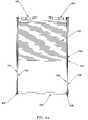
- FIG. 1Ais an illustrative perspective view of an inside face of an airplane window assembly, according to one embodiment of the invention.
- FIG. 1Bis an illustrative perspective view of an outside face of the airplane window assembly of FIG. 1A .
- FIG. 2is an illustrative perspective view of a translucent shade assembly, according to one embodiment of the invention.
- FIG. 3is an illustrative perspective view of an opaque shade assembly, according to one embodiment of the invention.
- FIG. 4Ais an illustrative front view of the translucent and opaque shade assemblies combined with an opaque shade motor assembly, a translucent shade motor assembly, and a lower drive assembly, according to one embodiment of the invention.
- FIG. 4Bis an illustrative left side view of the combined assemblies of FIG. 4A .
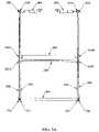
- FIG. 5Ais an illustrative front view of translucent shade and opaque shade gear belts combined with an opaque shade motor assembly, a translucent shade motor assembly, a lower drive assembly, a translucent shade lead assembly, and an opaque shade lead assembly, according to one embodiment of the invention.
- FIG. 5Bis an illustrative expanded perspective view of a portion of FIG. 5A and, in particular, of the right end of the translucent shade lead assembly and the right end of the opaque shade lead assembly respectively coupled to the gear belts.
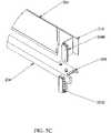
- FIG. 5Cis an illustrative perspective view of the right end of the translucent shade lead assembly and the right end of the opaque shade lead assembly shown in FIG. 5B .
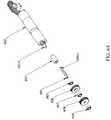
- FIG. 6Ais an illustrative exploded perspective view of an opaque shade motor assembly, according to one embodiment of the invention.
- FIG. 6Bis an illustrative exploded perspective view of a translucent shade motor assembly, according to one embodiment of the invention.
- FIG. 7Ais an illustrative front view of a lower drive assembly, according to one embodiment of the invention.
- FIG. 7Bis an illustrative perspective view of the individual components of the lower drive assembly shown in FIG. 7A .
- FIG. 7Cis an illustrative exploded perspective view of the left end of the lower drive assembly shown in FIG. 7A .
- FIG. 7Dis an illustrative exploded perspective view of the right end of the lower drive assembly shown in FIG. 7A .
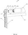
- FIG. 8Ais an illustrative perspective view of the opaque shade motor assembly coupled to the left opaque shade gear belt and the left translucent shade gear belt, according to an embodiment of the invention.
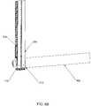
- FIG. 8Bis an illustrative perspective view of the left opaque shade gear belt and the left translucent shade gear belt coupled to the lower drive assembly, according to one embodiment of the invention.
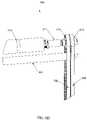
- FIG. 8Cis an illustrative perspective view of the lower drive assembly coupled to the right opaque shade gear belt and the right translucent shade gear belt, according to one embodiment of the invention.
- FIG. 8Dis an illustrative perspective view of the translucent shade motor assembly coupled to the right opaque shade gear belt and the right translucent shade gear belt, according to embodiment of the invention.
- FIG. 9is an illustrative front view of the motorized window shade mechanism including control electronics, according to one embodiment of the invention.
- FIG. 10is an illustrative block diagram of the control electronics for the motorized window shade mechanism, according to one embodiment of the invention.
- An airplane window assemblyincludes a motorized window shade mechanism.
- the window assemblyincludes an opaque shade and a translucent shade.
- the opaque shadeprovides total light blockage while the translucent shade allows a certain percentage of light to pass through.
- the window assemblyfurther includes two reversible motors disposed at the top of the window assembly. Each shade is raised and lowered by a separate gear and belt system that is driven by one of the motors.
- the window assembly 100includes a shell (or housing) 110 , which houses various electronic and mechanical components for enabling the window assembly to function, as described in detail below.
- the shell 110defines an inside opening 108 and an outside opening 109 aligned therewith, and has a first (or top) end 120 , a second (or bottom) end 121 , a first (or left) sidewall 122 , and a second (or right) sidewall 123 .
- the window assembly 100further includes an inside lens (i.e., a window pane) 112 , an outside lens (i.e., a window pane) 117 , a translucent shade 105 , an opaque shade 115 , and control buttons 107 (shade up button 107 a , shade down button 107 b ).
- an inside lensi.e., a window pane
- an outside lensi.e., a window pane
- a translucent shade 105i.e., an opaque shade 115
- control buttons 107shade up button 107 a , shade down button 107 b .
- the inside lens 112is disposed inside the shell 110 and over the inside opening 108
- the outside lens 117is disposed inside the shell 110 and over the outside opening 109
- the translucent shade 105is disposed inside the shell 110 and between the lenses 112 , 117
- the opaque shade 115is disposed inside the shell 110 and between the outside lens 117 and the translucent shade 105 .
- the window assembly 100functions generally as described below.
- a passenger wishing to reduce the light passing through the inner and outer lenses 112 , 117can lower, or extend, the translucent shade 105 to any desired position by pressing the shade-down button 107 b disposed at the bottom of window assembly 100 . While the passenger is holding down the button 107 b , the translucent shade 105 extends downward between the inner lens 112 and the outer lens 117 . If the passenger stops pressing the button 107 b , the translucent shade 105 immediately stops extending. The passenger can use the shade-up button 107 a to raise, or retract, the translucent shade 105 .
- the opaque shade 115begins to extend downward between the inner lens 112 and the outer lens 117 , and behind the translucent shade 105 .
- the passengercan selectively position the opaque shade 115 with the up and down buttons 107 a , 107 b.
- both the translucent shade 105 and the opaque shade 115are fully extended, all light is prevented from passing through the inner and outer lenses 112 , 117 . If the passenger wishes to raise the translucent and opaque shades 105 , 115 , the passenger need only press the shade-up button 107 a . When the shade-up button 107 a is pressed, the opaque shade 115 retracts first, leaving the translucent shade 105 fully extended. If the passenger continues to press the up button 107 a after the opaque shade 115 has fully retracted, the translucent shade 105 starts to retract. The translucent shade 105 continues to retract until the passenger stops pressing the shade-up button 107 a or the translucent shade 105 reaches a fully retracted position.
- a flight attendant or pilotcan remotely override every passenger's positioning of their individual translucent and opaque shades 105 , 115 .
- the flight attendantmay choose to completely lower the translucent and opaque shades 105 , 115 for all the windows during the viewing of an in-flight movie, or fully raise the translucent and opaque shades 105 , 115 in preparation for landing.
- the translucent shade assemblyincludes the translucent shade 105 , a translucent shade upper support 202 , a translucent shade lead assembly 204 , a left translucent shade gear belt 206 , and a right translucent shade gear belt 208 .
- the translucent shade 105includes a top or fixed end 210 and a bottom or free end 211 .
- Gear belts 206 , 208are preferably timing belts which have protrusions extending radially which engage within recesses on the outer periphery of the gears.
- the fixed end 210is attached to the upper support 202 , which is fixed at the top of shell 110 by having its ends secured to the first and second sidewalls 122 , 123 ( FIG. 1 ).
- the free end 211is attached to the lead assembly 204 , which extends horizontally between the first and second sidewalls 122 , 123 .
- the left translucent shade gear belt 206extends vertically along the left sidewall 122
- the right translucent shade gear belt 208extends vertically along the right sidewall 123 .
- the lead assembly 204is coupled to the left and right gear belts 206 , 208 by left and right clips, which are discussed in further detail with respect to FIGS. 5A-5C .
- the opaque shade assemblyincludes the opaque shade 115 , an opaque shade axle assembly 302 , an opaque shade lead assembly 304 , a left opaque shade gear belt 306 , and a right opaque shade gear belt 308 .
- the translucent shade 115includes a top, or fixed, end 310 and a bottom, or free, end 311 .
- the fixed end 310is a spring-loaded roller which keeps tension on the opaque shade as it is extended and retracted.
- the rolleris installed on the opaque shade axle assembly 302 , which is fixed at the top of shell 110 by having its ends secured to the first and second sidewalls 122 , 123 ( FIG. 1 ).
- the free end 311is coupled to the lead assembly 304 , which extends horizontally between the first and second sidewalls 122 , 123 .
- the left opaque shade gear belt 306extends vertically along the left sidewall 122
- the right opaque shade gear belt 308extends vertically along the right sidewall 123 .
- the lead assembly 304is coupled to the left and right gear belts 306 , 308 by left and right clips, which are discussed in further detail with respect to FIGS. 5A-5C .
- FIG. 4Ain one embodiment, an illustrative front view of the translucent and opaque shade assemblies combined with an opaque shade motor assembly 402 , a translucent shade motor assembly 404 , and a lower drive assembly 406 is shown.
- FIG. 4Bis an illustrative left side view of the combined assemblies of FIG. 4A .
- the translucent shade 105is in front (i.e. closer to the interior of the aircraft) of the opaque shade 115 .
- the left translucent shade gear belt 206 and the left opaque shade gear belt 306are coupled to the opaque shade motor assembly 402 and a left end 407 of the lower drive assembly 406 (described in detail below in connection with FIGS. 7A-7D ).
- the right translucent shade gear belt 208 and the right opaque shade gear belt 308are coupled to the translucent motor assembly 404 and a right end 408 of the lower drive assembly 406 .
- the lead assembly 204is coupled to the left and right gear belts 206 , 208 by left and right clips, which are discussed in further detail with respect to FIGS. 5A-5D .
- the lead assembly 304is coupled to the left and right gear belts 306 , 308 by left and right clips, which are discussed in further detail with respect to FIGS. 5A-5D .
- the particular couplings of the gear belts 206 , 208 , 306 , 308are discussed in further detail with respect to FIGS. 6A-6B and FIGS. 7A-7D .
- the opaque shade 115is flat and very thin. It can be retracted (rolled-up) or extended (unrolled) from the opaque shade axle assembly 302 .
- the translucent shade 105is either pleated or has any other suitable configuration allowing it to be highly compressed upon retraction and expanded upon extension.
- the translucent shade 105is designed to be aesthetically attractive whereas opaque shade 115 is designed to be functional. Therefore, the preferred embodiment of the invention prevents opaque shade 115 from being visible to the passengers. This is done by ensuring, mechanically and/or electronically, that shade 105 always covers shade 115 .
- an illustrative front view of the translucent and opaque shade gear belts 206 , 208 , 306 , 308 combined together with the reversible opaque shade motor assembly 402 , the reversible translucent shade motor assembly 404 , the lower drive assembly 406 , the translucent shade lead assembly 204 , and the opaque shade lead assembly 304is shown.
- shades 105 , 115are not shown.
- the translucent shade lead assembly 204is coupled to the left and right gear belts 206 , 208 with clips 502 a and 502 b , respectively.
- the opaque shade lead assembly 304is coupled to the left and right gear belts 306 , 308 with clips 504 a and 504 b respectively.
- the opaque shade lead assembly 304sits above the translucent shade lead assembly 204 .
- the opaque shade 115In operation, the opaque shade 115 always retracts before, and extends after, the translucent shade 105 . This is accomplished by the design and timing of the system, and by the design of the lead assemblies 204 and 304 and the clips 502 a - b and 504 a - b . The opaque shade 115 is thus never seen by the passenger as it is always covered by the translucent shade 105 .
- the translucent shade lead assembly 204includes an extending member 508 and the opaque shade lead assembly includes a flat portion 510 that is perpendicular to the extending member 508 .
- the translucent shade 105 and the opaque shade 115can be manually raised or lowered via a thumb wheel (described in connection with FIGS. 7A and 7B ) on the front of the shell 110 .
- a thumb wheeldescribed in connection with FIGS. 7A and 7B .
- the extending portion 508contacts the perpendicular flat portion 510 to retract both shades 105 and 115 upward together.
- the perpendicular flat portion 510contacts the extending portion 508 , which prevents the opaque shade 115 from descending past the translucent shade 105 and, thereby, becoming visible to the passengers.
- the opaque motor assembly 402includes a reversible motor 602 , motor shaft 602 a , a coupler 603 for coupling motor shaft 602 a to a shaft 604 , ball bearings 605 , 607 , 609 , a passive (or free turning) gear 606 , and a driving gear 608 .
- Ball bearings 605 , 607 , 609fit into openings in a motor mount (not shown) which secures the opaque motor assembly 402 to shell 110 .
- Passive gear 606has an inner radius that allows it to rotate freely on the circular periphery of shaft 604 .
- driven gear 608has an opening shaped to engage splines 604 a formed on shaft 604 .
- the reversible motor 602when the reversible motor 602 is running, the reversible motor 602 (via shaft 602 a and coupler 603 ) turns the shaft 604 , which turns (drives) the driving gear 608 .
- the driving gear 608then drives the left opaque shade gear belt 306 .
- the passive gear 606rotates freely on shaft 604 and remains stationary unless it is driven by the left translucent shade gear belt 206 .
- the translucent motor assembly 404includes a reversible motor 610 , a motor shaft 610 a , a coupler 611 for coupling motor shaft 610 a to a shaft 612 , ball bearing 613 , 615 , 617 , a driving gear 614 , and a passive gear 616 .
- Ball bearings 613 , 615 , 617fit into openings in a motor mount (not shown) which secures the translucent motor assembly 404 to shell 110 .
- Passive gear 616has an inner radius that allows it to rotate freely on the circular periphery of shaft 612 .
- driving gear 614has an opening shaped to engage splines 612 a formed on shaft 612 .
- Motors 602 and 610are available from Portescap as Part No. 1017130019. These motors integrate into one structure a motor (Product Code 13N), a planetary gearbox (Product Code R13), and an encoder.
- the reversible motor 610when the reversible motor 610 is running, the reversible motor 610 turns the shaft 612 , which turns (drives) the driving gear 614 .
- the driving gear 614then drives the right translucent shade gear belt 208 .
- the passive gear 616rotates freely on the shaft 612 and remains stationary unless it is driven by the right opaque shade gear belt 308 .
- the lower drive assembly 406includes an inner axle 702 mounted within an outer axle 704 , pillow blocks 706 , 734 , ball bearings 708 , 714 , 726 , 732 , first paired driven gears 710 , 730 , second paired driven gears 712 , 728 , and a manual override window shade mechanism 750 .
- the manual override window shade mechanism 750includes a bevel gear housing 720 , an active bevel gear 718 , a pinion bevel gear 722 , and needle bearing 716 , 724 .
- First paired driven gears 710 , 730are mounted in vertical alignment with opaque shade gears 608 , 616 .
- second paired driven gears 712 , 728are mounted in vertical alignment with translucent shade gears 606 , 614 . This alignment facilitates the movement of belts 206 , 208 , 306 and 308 .
- Ball bearings 714 , 726are pressed onto opposite ends of inner axle 702 passed the splined ends 742 a , 744 a and are sized to fit tightly within outer axle 704 .
- Ball bearings 714 , 726thus enable inner axle 702 to rotate within and independently of outer axle 704 .
- Ball bearings 708 , 732fit respectively within pillow blocks 706 , 734 which are secured to shell 110 . With ball bearings 708 , 732 on opposite tips of inner axle 702 , it can rotate relative to shell 110 .
- this arrangementallows inner axle 702 to rotate on shell 110 , with outer axle 704 and inner axle 702 being rotatable independently of each other.
- the first paired driven gears 710 , 730are on opposite ends of inner axle 702 .
- Splined ends 742 a , 744 adrivingly engage correspondingly shaped openings 710 a , 730 a in driven gears 710 , 730 .
- the second paired driven gears 712 , 728are on opposite ends 740 , 746 of outer axle 704 .
- the five-sided peripheral shape of ends 740 , 746correspond to and drivingly engage openings 712 a , 728 a in gears 712 , 728 .
- the reversible motor 602when the reversible motor 602 ( FIG. 6A ) is running, the reversible motor 602 turns the shaft 604 , which turns (drives) the driving gear 608 .
- the driving gear 608then drives the left opaque shade gear belt 306 (see FIG. 8A ).
- the left opaque shade gear belt 306which is coupled to the driving gear 710 , drives gear 710 , which is coupled to the left end 742 of the inner axle 702 (see also FIG. 8B ).
- the right end 744 of the inner axle 702is coupled to the driven gear 730 .
- the inner axle 702drives the gear 730 , which then drives the right opaque shade gear belt 308 (see FIG. 8C ).
- the right opaque shade gear belt 308then turns the passive gear 616 (see FIG. 8D ).
- the reversible motor 610when the reversible motor 610 ( FIG. 6B ) is running, the reversible motor 610 turns the shaft 612 , which turns (drives) the driving gear 614 .
- the driving gear 614then drives the right translucent shade gear belt 208 (see FIG. 8D ).
- the right translucent shade gear belt 208which is coupled to the gear 728 , drives the driven gear 728 , which is coupled to the right end 746 of the outer axle 704 (see also FIG. 8C ).
- the driven gear 728turns the outer axle 704 .
- the left end 740 of the outer axle 704is coupled to the driven gear 712 .
- the outer axle 704drives the gear 712 , which then drives the left translucent shade gear belt 206 (see FIG. 8B ).
- the left translucent shade gear belt 206then turns the passive gear 606 (see also FIG. 8A ).
- rotation of motor shaft 602 ais applied by belts 306 , 308 uniformly to opaque shade 115 so that it moves smoothly up and down under motor power without binding.
- rotation of motor shaft 610 ais applied by belts 206 , 208 uniformly to translucent shade 115 so that it moves smoothly up and down under motor power without binding.
- the manual override window shade mechanism 750includes the bevel gear housing 720 , the active bevel gear 718 , which is fixed, such as by a set screw, to outer axle 704 , the pinion bevel gear 722 , and the bearings 716 , 724 .
- Bearings 716 , 724enable outer axle 704 to rotate with respect to housing 720 .
- Housing 720is suitably secured in any well known manner to shell 110 .
- the window shade mechanismIn operation, when the window shade mechanism is operated manually, a passenger turns a thumbwheel (not shown) at the bottom of shell 110 that turns the pinion bevel gear 722 .
- the pinion bevel gear 722engages and turns the active bevel gear 718 , which causes the outer axle 704 to turn.
- the outer axle 704then drives the paired driven gears 712 , 728 , which drive the translucent shade gear belts 206 , 208 .
- the translucent shade lead 204includes the extending portion 508 .
- the extending portion 508contacts the perpendicular flat portion 510 of the opaque shade lead 304 when the translucent shade is manually raised and thereby raises the opaque shade 115 . Further, because of the extending portion 508 , the opaque shade lead 304 will never fall below the translucent shade lead 204 , when the translucent shade 105 is manually lowered.
- FIG. 9another illustrative front view of a motorized window shade mechanism in accordance with an embodiment of the invention is shown.
- the opaque motor assembly 402 and translucent motor assembly 404are controlled by control electronics 902 , as described in detail with respect to FIG. 10 .
- control electronics 902for the motorized window shade mechanism.
- the control electronics 902include an upper circuit board 1001 and a lower circuit board 1002 .
- the upper circuit board 1001 and the lower circuit board 1002are in communication via a connection between connector J 6 and connector J 8 and a connection between connector J 7 and connector J 9 .
- the upper circuit board 1001includes passenger switches interface 1006 , address switches 1008 , seek switch 1010 , 3.3 VDC power supply 1012 , motor tachometer feedback circuit 1018 , processor 1016 , CAN bus interface 1014 and connector J 2 .
- the lower circuit board 1002includes motor driver 1026 , motor driver 1028 , remote switches interface 1030 , 5 VDC supply 1032 , 28 VDC monitor 1034 , connector J 1 , connector J 3 , and connector J 4 .
- the processor 1016controls all of the functions of the window shade mechanism.
- the processor 1016can be, for example, an 8051 microcontroller.
- the processoris, in turn, controlled by the passenger switches 107 (via the connector J 2 ) or by remote switches 1044 .
- the remote switches 1044are operated by a flight attendant or a pilot, and can be located at a flight attendant station or pilot cabin.
- the remote switchesare connected to connector P 1 , which is connected to cable 1042 .
- the cable 1042is connected to connector P 2 , which communicates with the lower circuit board 1002 via connector J 1 .
- the connector J 1is connected to the remote switches interface 1030 , which communicates with the processor 1016 via a connection between connector J 9 and connector J 7 .
- the processor 1016Upon receiving a command from the passenger switches 107 or the remote switches 1044 , the processor 1016 communicates with the motor driver 1026 and/or the motor driver 1028 to actuate the reversible motor 610 (translucent shade) and/or the reversible motor 602 (opaque shade), respectively.
Landscapes
- Engineering & Computer Science (AREA)
- Mechanical Engineering (AREA)
- Aviation & Aerospace Engineering (AREA)
- Operating, Guiding And Securing Of Roll- Type Closing Members (AREA)
- Power-Operated Mechanisms For Wings (AREA)
Abstract
Description
Claims (26)
Priority Applications (4)
| Application Number | Priority Date | Filing Date | Title |
|---|---|---|---|
| US11/645,981US7690414B2 (en) | 2006-12-26 | 2006-12-26 | Motorized window shade |
| EP14181814.6AEP2826942B1 (en) | 2006-12-26 | 2007-12-27 | Motorized window shade |
| EP07124108.7AEP1939389B1 (en) | 2006-12-26 | 2007-12-27 | Motorized window shade |
| CA2616571ACA2616571C (en) | 2006-12-26 | 2007-12-27 | Motorized window shade |
Applications Claiming Priority (1)
| Application Number | Priority Date | Filing Date | Title |
|---|---|---|---|
| US11/645,981US7690414B2 (en) | 2006-12-26 | 2006-12-26 | Motorized window shade |
Publications (2)
| Publication Number | Publication Date |
|---|---|
| US20080148638A1 US20080148638A1 (en) | 2008-06-26 |
| US7690414B2true US7690414B2 (en) | 2010-04-06 |
Family
ID=39125209
Family Applications (1)
| Application Number | Title | Priority Date | Filing Date |
|---|---|---|---|
| US11/645,981Expired - Fee RelatedUS7690414B2 (en) | 2006-12-26 | 2006-12-26 | Motorized window shade |
Country Status (3)
| Country | Link |
|---|---|
| US (1) | US7690414B2 (en) |
| EP (2) | EP2826942B1 (en) |
| CA (1) | CA2616571C (en) |
Cited By (26)
| Publication number | Priority date | Publication date | Assignee | Title |
|---|---|---|---|---|
| US20090283227A1 (en)* | 2008-05-13 | 2009-11-19 | Msa Aircraft Products Ltd. | Clutch operated electric aircraft window with manual override |
| US20090314439A1 (en)* | 2008-06-18 | 2009-12-24 | Steve Waters | Window shade |
| US20100126676A1 (en)* | 2008-11-22 | 2010-05-27 | Diehl Aircabin Gmbh | Device for darkening a cabin window |
| US20110108208A1 (en)* | 2009-11-11 | 2011-05-12 | Aerospace Technologies Group, Inc. | Window Assembly with a Motorized Window Shade Mechanism |
| US8157214B2 (en)* | 2007-02-09 | 2012-04-17 | Airbus Deutschland Gmbh | Aircraft window darkening system |
| WO2012097176A1 (en)* | 2011-01-13 | 2012-07-19 | Aerospace Technologies Group, Inc. | Systems and methods for installing motorized window shade mechanism in aircraft |
| US20140048219A1 (en)* | 2011-01-13 | 2014-02-20 | Aerospace Technologies Group Inc. | Motorized window shade mechanism |
| US20140209746A1 (en)* | 2013-01-29 | 2014-07-31 | The Boeing Company | Window shading assembly |
| WO2014169093A1 (en)* | 2013-04-11 | 2014-10-16 | Qmotion Incorporated | Motorized drapery apparatus, system and method of use |
| US20140376072A1 (en)* | 2013-06-20 | 2014-12-25 | Airbus Operations Gmbh | Window shade and window element |
| US20150267465A1 (en)* | 2012-10-15 | 2015-09-24 | Aerospace Technologies Group Inc. | Emergency override release mechanism for motorized window shade assembly |
| US20150345212A1 (en)* | 2013-01-22 | 2015-12-03 | Htp High Tech Plastics Gmbh | Apparatus for covering a view opening |
| US9221320B2 (en) | 2013-09-18 | 2015-12-29 | Honda Motor Co., Ltd. | Methods and systems for shading a window |
| US9615687B2 (en) | 2012-09-17 | 2017-04-11 | Current Products Corp. | Rotatable drive element for moving a window covering |
| US9801486B2 (en) | 2014-05-19 | 2017-10-31 | Current Products Corp. | Crossover bracket for drapery |
| US10145171B2 (en)* | 2011-03-07 | 2018-12-04 | Hunter Douglas Inc. | Control for movable rail |
| USD840957S1 (en)* | 2016-12-20 | 2019-02-19 | Gentex Corporation | Dimming switch |
| EP3626495A1 (en)* | 2018-09-19 | 2020-03-25 | The Boeing Company | Window assembly for use in a vehicle |
| US10754219B2 (en) | 2017-06-29 | 2020-08-25 | Gentex Corporation | Addressable electro-optic device |
| US11059560B2 (en) | 2018-09-19 | 2021-07-13 | The Boeing Company | Window assembly for use in a vehicle |
| US11457763B2 (en) | 2019-01-18 | 2022-10-04 | Current Products Corp. | Stabilized rotating drapery rod ring system |
| US20240059392A1 (en)* | 2022-08-22 | 2024-02-22 | Textron Aviation Inc. | Window Roller Shade and Dimming Pane |
| US12017749B2 (en)* | 2022-03-23 | 2024-06-25 | Aerospace Technologies Group, Inc. | Electrically operated window shade assembly for an aircraft window having opaque and translucent shades |
| EP4395119A2 (en) | 2022-12-29 | 2024-07-03 | Mario Ceste | Emergency backup power source and control circuit for electrically operated aircraft window shades |
| EP4488168A3 (en)* | 2023-07-07 | 2025-01-22 | B/E Aerospace, Inc. | Business class suites with interior window and illuminated window shade |
| US20250174479A1 (en)* | 2023-11-27 | 2025-05-29 | Samsung Electronics Co., Ltd. | Wafer container |
Families Citing this family (13)
| Publication number | Priority date | Publication date | Assignee | Title |
|---|---|---|---|---|
| DE202009003840U1 (en)* | 2008-11-22 | 2010-04-29 | Diehl Aircabin Gmbh | Device for darkening a cabin window |
| FR2943715B1 (en)* | 2009-03-31 | 2016-07-01 | Vision Systems Aeronautics | STORAGE ASSEMBLY, IN PARTICULAR FOR AN AIRCRAFT DOOR, COMPRISING MEANS FOR MAINTAINING VOLTAGE |
| DE202010004404U1 (en) | 2010-03-31 | 2010-07-01 | Aero Engineering Gmbh | Window shading device |
| US20120222827A1 (en)* | 2011-03-02 | 2012-09-06 | Ryan Voges | Motorized window shade system |
| WO2013040054A1 (en)* | 2011-09-12 | 2013-03-21 | Aerospace Technologies Group, Inc. | Window shade assembly with manual actuator mechanism |
| US20150284995A1 (en)* | 2014-04-07 | 2015-10-08 | Ryan Voges | Motorized window shade system |
| USD741084S1 (en)* | 2013-03-26 | 2015-10-20 | Oceanair Marine Limited | Blind unit for a yacht deck hatch |
| US9815351B2 (en)* | 2015-07-08 | 2017-11-14 | Eduardus Leonardus Gennissen | Window or door covering assembly for a vehicle |
| US10596883B2 (en)* | 2017-06-27 | 2020-03-24 | Bauer Products, Inc. | Vent shade assembly |
| US10730367B2 (en) | 2017-06-27 | 2020-08-04 | Bauer Products, Inc. | Vent shade assembly |
| CA3172174A1 (en)* | 2020-03-18 | 2021-09-23 | Toralf H. Strand | Hybrid covering for an architectural structure |
| USD918619S1 (en)* | 2020-04-29 | 2021-05-11 | Foshan Bestwyll Auto Accessories Co., Ltd | Roller shade |
| US20240221460A1 (en)* | 2022-12-29 | 2024-07-04 | Interblock D.O.O. | Method for revealing dice results |
Citations (22)
| Publication number | Priority date | Publication date | Assignee | Title |
|---|---|---|---|---|
| US2647572A (en)* | 1950-01-10 | 1953-08-04 | Percival H Biscoe | Venetian blind |
| US3186473A (en)* | 1960-01-06 | 1965-06-01 | Darwin E Myers | Means for controlling the light entering a room window |
| US3568751A (en)* | 1968-10-12 | 1971-03-09 | Sasuke Takahashi | Large motion picture screen rolling-up equipment |
| US4807686A (en) | 1987-02-25 | 1989-02-28 | Comfortex Corporation | Shade system |
| US4998576A (en)* | 1989-09-29 | 1991-03-12 | Msa Aircraft Interior Products, Inc. | Reversing screw, aircraft window shade mechanism for a modular aircraft window |
| US5035091A (en)* | 1988-12-30 | 1991-07-30 | Kabushiki Kaisha Daimon | Automatically operated opening and closing roof |
| US5195569A (en)* | 1987-04-13 | 1993-03-23 | Daylighting, Inc. | Closed loop control system for shade assembly |
| US5515898A (en)* | 1994-12-23 | 1996-05-14 | A & C Products | Operating mechanism for aircraft window shades |
| US6035917A (en)* | 1997-03-20 | 2000-03-14 | Ravco Innovations, Inc. | Foldable security bar assembly |
| US6186211B1 (en)* | 1999-02-22 | 2001-02-13 | Aerospace Technologies Group, Inc. | Window assembly with a motorized window shade mechanism |
| US6230784B1 (en)* | 1997-09-25 | 2001-05-15 | Msa Aircraft Products Ltd. | Electrically operated aircraft window with a sliding take-up spool |
| US20020053410A1 (en)* | 2000-01-20 | 2002-05-09 | Michael Mayr | Insulating glass pane comprising an integrated roller blind device |
| US6460805B1 (en)* | 2000-08-24 | 2002-10-08 | Msa Aircraft Products, Ltd. | Double convex aircraft window |
| DE20209724U1 (en) | 2001-07-03 | 2002-11-14 | Lutz, Franz, 86657 Bissingen | Insulating glass pane with integrated, motor-driven sun protection or blackout cover |
| US6481486B1 (en)* | 2000-02-08 | 2002-11-19 | Msa Aircraft Products, Ltd. | Modular aircraft window with a dual shade |
| US20040040672A1 (en)* | 2002-08-29 | 2004-03-04 | Haim Nagar | Device and method for shading a window |
| US6745810B1 (en)* | 2001-01-05 | 2004-06-08 | Msa Aircraft Interior Products, Inc. | Handle operated modular window shade system for moving a shade vertically a distance less than the distance of handle travel |
| US6832641B1 (en)* | 1999-11-17 | 2004-12-21 | Eduardo Sanz | Electric dual shade aircraft window |
| US6915988B2 (en)* | 2003-01-27 | 2005-07-12 | Msa Aircraft Products, Ltd. | Matrix window |
| US20050263254A1 (en)* | 2004-05-27 | 2005-12-01 | Sievers Thomas J | Window shade positioning apparatus and method |
| US7234501B1 (en)* | 2006-06-02 | 2007-06-26 | Park Hubert H | External blind actuator for sealed double glazed window |
| US7481260B2 (en)* | 2004-01-09 | 2009-01-27 | Hagen Holding Aps | Tightening device for blinds |
- 2006
- 2006-12-26USUS11/645,981patent/US7690414B2/ennot_activeExpired - Fee Related
- 2007
- 2007-12-27EPEP14181814.6Apatent/EP2826942B1/ennot_activeNot-in-force
- 2007-12-27EPEP07124108.7Apatent/EP1939389B1/ennot_activeNot-in-force
- 2007-12-27CACA2616571Apatent/CA2616571C/ennot_activeExpired - Fee Related
Patent Citations (28)
| Publication number | Priority date | Publication date | Assignee | Title |
|---|---|---|---|---|
| US2647572A (en)* | 1950-01-10 | 1953-08-04 | Percival H Biscoe | Venetian blind |
| US3186473A (en)* | 1960-01-06 | 1965-06-01 | Darwin E Myers | Means for controlling the light entering a room window |
| US3568751A (en)* | 1968-10-12 | 1971-03-09 | Sasuke Takahashi | Large motion picture screen rolling-up equipment |
| US4807686A (en) | 1987-02-25 | 1989-02-28 | Comfortex Corporation | Shade system |
| US5195569A (en)* | 1987-04-13 | 1993-03-23 | Daylighting, Inc. | Closed loop control system for shade assembly |
| US5035091A (en)* | 1988-12-30 | 1991-07-30 | Kabushiki Kaisha Daimon | Automatically operated opening and closing roof |
| US4998576A (en)* | 1989-09-29 | 1991-03-12 | Msa Aircraft Interior Products, Inc. | Reversing screw, aircraft window shade mechanism for a modular aircraft window |
| US5082043A (en)* | 1989-09-29 | 1992-01-21 | Msa Aircraft Interior Products, Inc. | Window shade mechanism for a modular aircraft window |
| US5515898A (en)* | 1994-12-23 | 1996-05-14 | A & C Products | Operating mechanism for aircraft window shades |
| US6035917A (en)* | 1997-03-20 | 2000-03-14 | Ravco Innovations, Inc. | Foldable security bar assembly |
| US6230784B1 (en)* | 1997-09-25 | 2001-05-15 | Msa Aircraft Products Ltd. | Electrically operated aircraft window with a sliding take-up spool |
| US6186211B1 (en)* | 1999-02-22 | 2001-02-13 | Aerospace Technologies Group, Inc. | Window assembly with a motorized window shade mechanism |
| US20010011580A1 (en)* | 1999-02-22 | 2001-08-09 | Aerospace Technologies Group, Inc. | Window assembly with a motorized window shade mechanism |
| EP1674650A2 (en) | 1999-02-22 | 2006-06-28 | Aerospace Technologies Group, Inc. | Window shade assembly with a motorized window shade mechanism |
| US6832641B1 (en)* | 1999-11-17 | 2004-12-21 | Eduardo Sanz | Electric dual shade aircraft window |
| US20020053410A1 (en)* | 2000-01-20 | 2002-05-09 | Michael Mayr | Insulating glass pane comprising an integrated roller blind device |
| US6530414B2 (en)* | 2000-01-20 | 2003-03-11 | Michael Mayr | Insulating glass pane comprising an integrated roller blind device |
| US20030085001A1 (en)* | 2000-02-08 | 2003-05-08 | Msa Aircraft Products, Ltd. A Texas Limited Partnership | Modular aircraft window with a dual shade |
| US6481486B1 (en)* | 2000-02-08 | 2002-11-19 | Msa Aircraft Products, Ltd. | Modular aircraft window with a dual shade |
| US6460805B1 (en)* | 2000-08-24 | 2002-10-08 | Msa Aircraft Products, Ltd. | Double convex aircraft window |
| US6745810B1 (en)* | 2001-01-05 | 2004-06-08 | Msa Aircraft Interior Products, Inc. | Handle operated modular window shade system for moving a shade vertically a distance less than the distance of handle travel |
| EP1273754A1 (en)* | 2001-07-03 | 2003-01-08 | Michael Mayr | Insulation glass unit with integrated, power driven sunshield- or darkening blind |
| DE20209724U1 (en) | 2001-07-03 | 2002-11-14 | Lutz, Franz, 86657 Bissingen | Insulating glass pane with integrated, motor-driven sun protection or blackout cover |
| US20040040672A1 (en)* | 2002-08-29 | 2004-03-04 | Haim Nagar | Device and method for shading a window |
| US6915988B2 (en)* | 2003-01-27 | 2005-07-12 | Msa Aircraft Products, Ltd. | Matrix window |
| US7481260B2 (en)* | 2004-01-09 | 2009-01-27 | Hagen Holding Aps | Tightening device for blinds |
| US20050263254A1 (en)* | 2004-05-27 | 2005-12-01 | Sievers Thomas J | Window shade positioning apparatus and method |
| US7234501B1 (en)* | 2006-06-02 | 2007-06-26 | Park Hubert H | External blind actuator for sealed double glazed window |
Cited By (39)
| Publication number | Priority date | Publication date | Assignee | Title |
|---|---|---|---|---|
| US8157214B2 (en)* | 2007-02-09 | 2012-04-17 | Airbus Deutschland Gmbh | Aircraft window darkening system |
| US20090283227A1 (en)* | 2008-05-13 | 2009-11-19 | Msa Aircraft Products Ltd. | Clutch operated electric aircraft window with manual override |
| US20090314439A1 (en)* | 2008-06-18 | 2009-12-24 | Steve Waters | Window shade |
| US8220521B2 (en)* | 2008-11-22 | 2012-07-17 | Diehl Aircabin Gmbh | Device for darkening a cabin window |
| US20100126676A1 (en)* | 2008-11-22 | 2010-05-27 | Diehl Aircabin Gmbh | Device for darkening a cabin window |
| US9045215B2 (en)* | 2009-11-11 | 2015-06-02 | Aerospace Technologies Group, Inc. | Window assembly with a motorized window shade mechanism |
| US20110108208A1 (en)* | 2009-11-11 | 2011-05-12 | Aerospace Technologies Group, Inc. | Window Assembly with a Motorized Window Shade Mechanism |
| WO2012097176A1 (en)* | 2011-01-13 | 2012-07-19 | Aerospace Technologies Group, Inc. | Systems and methods for installing motorized window shade mechanism in aircraft |
| US20130340957A1 (en)* | 2011-01-13 | 2013-12-26 | Byron R. Knowles | Technique to Facilitate Installation of Motorized Window Shade Mechanism in Aircraft |
| US20140048219A1 (en)* | 2011-01-13 | 2014-02-20 | Aerospace Technologies Group Inc. | Motorized window shade mechanism |
| US9919788B2 (en)* | 2011-01-13 | 2018-03-20 | Aerospace Technologies Group, Inc. | Technique to facilitate installation of motorized window shade mechanism in aircraft |
| EP2663489A4 (en)* | 2011-01-13 | 2016-02-24 | Aerospace Technologies Group Inc | Systems and methods for installing motorized window shade mechanism in aircraft |
| US11180952B2 (en) | 2011-03-07 | 2021-11-23 | Hunter Douglas Inc | Control for movable rail |
| US10145171B2 (en)* | 2011-03-07 | 2018-12-04 | Hunter Douglas Inc. | Control for movable rail |
| US9615687B2 (en) | 2012-09-17 | 2017-04-11 | Current Products Corp. | Rotatable drive element for moving a window covering |
| US20150267465A1 (en)* | 2012-10-15 | 2015-09-24 | Aerospace Technologies Group Inc. | Emergency override release mechanism for motorized window shade assembly |
| US9677329B2 (en)* | 2012-10-15 | 2017-06-13 | Aerospace Technologies Group, Inc. | Emergency override release mechanism for motorized window shade assembly |
| US20150345212A1 (en)* | 2013-01-22 | 2015-12-03 | Htp High Tech Plastics Gmbh | Apparatus for covering a view opening |
| US20140209746A1 (en)* | 2013-01-29 | 2014-07-31 | The Boeing Company | Window shading assembly |
| WO2014169093A1 (en)* | 2013-04-11 | 2014-10-16 | Qmotion Incorporated | Motorized drapery apparatus, system and method of use |
| US9999313B2 (en) | 2013-04-11 | 2018-06-19 | Current Products Corp. | Motorized drapery apparatus, system and method of use |
| US20140376072A1 (en)* | 2013-06-20 | 2014-12-25 | Airbus Operations Gmbh | Window shade and window element |
| US9567799B2 (en)* | 2013-06-20 | 2017-02-14 | Airbus Operations Gmbh | Window shade and window element |
| US9221320B2 (en) | 2013-09-18 | 2015-12-29 | Honda Motor Co., Ltd. | Methods and systems for shading a window |
| US9801486B2 (en) | 2014-05-19 | 2017-10-31 | Current Products Corp. | Crossover bracket for drapery |
| USD840957S1 (en)* | 2016-12-20 | 2019-02-19 | Gentex Corporation | Dimming switch |
| US10754219B2 (en) | 2017-06-29 | 2020-08-25 | Gentex Corporation | Addressable electro-optic device |
| US10988970B2 (en) | 2018-09-19 | 2021-04-27 | The Boeing Company | Window assembly for use in a vehicle |
| US11059560B2 (en) | 2018-09-19 | 2021-07-13 | The Boeing Company | Window assembly for use in a vehicle |
| EP3626495A1 (en)* | 2018-09-19 | 2020-03-25 | The Boeing Company | Window assembly for use in a vehicle |
| US11457763B2 (en) | 2019-01-18 | 2022-10-04 | Current Products Corp. | Stabilized rotating drapery rod ring system |
| US12017749B2 (en)* | 2022-03-23 | 2024-06-25 | Aerospace Technologies Group, Inc. | Electrically operated window shade assembly for an aircraft window having opaque and translucent shades |
| US12214859B1 (en) | 2022-03-23 | 2025-02-04 | Aerospace Technologies Group, Inc. | Electrically operated window shade assembly for an aircraft window having opaque and translucent shades |
| US20240059392A1 (en)* | 2022-08-22 | 2024-02-22 | Textron Aviation Inc. | Window Roller Shade and Dimming Pane |
| US12280865B2 (en)* | 2022-08-22 | 2025-04-22 | Textron Innovations Inc. | Window roller shade and dimming pane |
| EP4395119A2 (en) | 2022-12-29 | 2024-07-03 | Mario Ceste | Emergency backup power source and control circuit for electrically operated aircraft window shades |
| EP4395119A3 (en)* | 2022-12-29 | 2024-07-31 | Mario Ceste | Emergency backup power source and control circuit for electrically operated aircraft window shades |
| EP4488168A3 (en)* | 2023-07-07 | 2025-01-22 | B/E Aerospace, Inc. | Business class suites with interior window and illuminated window shade |
| US20250174479A1 (en)* | 2023-11-27 | 2025-05-29 | Samsung Electronics Co., Ltd. | Wafer container |
Also Published As
| Publication number | Publication date |
|---|---|
| EP2826942B1 (en) | 2018-04-11 |
| CA2616571C (en) | 2010-06-01 |
| CA2616571A1 (en) | 2008-06-26 |
| US20080148638A1 (en) | 2008-06-26 |
| EP1939389A1 (en) | 2008-07-02 |
| EP2826942A1 (en) | 2015-01-21 |
| EP1939389B1 (en) | 2014-10-08 |
Similar Documents
| Publication | Publication Date | Title |
|---|---|---|
| US7690414B2 (en) | Motorized window shade | |
| US6877868B2 (en) | Powered telescoping trailer tow mirror | |
| EP1659032B1 (en) | Display device for vehicle | |
| US4930255A (en) | Door window assembly | |
| CN102485518B (en) | The roller shutter type panorama roof of independent operation | |
| CN112918231A (en) | Panoramic sunroof with openable sunshade curtain | |
| US20060000565A1 (en) | Device for opening and closing a curtain, notably in order to automate the phases of opening and closing of the curtain | |
| US11214131B2 (en) | Vehicle integrated rain guard | |
| CN218858162U (en) | Automobile instrument board and automobile | |
| CN114734933B (en) | Driving assembly of hidden type car logo and car | |
| GB2173752A (en) | Apparatus for covering a window of a vehicle | |
| KR100873475B1 (en) | Sunshade for car rear | |
| CN210003107U (en) | transverse transmission electric window | |
| CN202541263U (en) | Automobile curtain system and curtain device | |
| CN105703533A (en) | Adjustable window covering driving device and using method thereof | |
| CN221213446U (en) | Roller blind system for vehicle sunroof and vehicle | |
| CN216546010U (en) | Vehicle-mounted display screen adjusting device and vehicle | |
| CN111216524B (en) | Solar shielding device for automobile | |
| CN222769232U (en) | Electric curtain rolling machine for vehicle | |
| JPH031648Y2 (en) | ||
| CN220865180U (en) | Sun-shading device and vehicle | |
| CN105799465A (en) | Intelligent lifting device for car window roller blind and application method of intelligent lifting device | |
| CN2263189Y (en) | Multifunctional window and door | |
| WO2023070601A1 (en) | Vehicle-mounted display screen adjusting device and vehicle | |
| CN120481628A (en) | Display screen device, display screen control method, instrument panel, and vehicle |
Legal Events
| Date | Code | Title | Description |
|---|---|---|---|
| AS | Assignment | Owner name:AEROSPACE TECHNOLOGIES GROUP, INC., FLORIDA Free format text:ASSIGNMENT OF ASSIGNORS INTEREST;ASSIGNOR:KNOWLES, BYRON;REEL/FRAME:018747/0522 Effective date:20061222 Owner name:AEROSPACE TECHNOLOGIES GROUP, INC.,FLORIDA Free format text:ASSIGNMENT OF ASSIGNORS INTEREST;ASSIGNOR:KNOWLES, BYRON;REEL/FRAME:018747/0522 Effective date:20061222 | |
| STCF | Information on status: patent grant | Free format text:PATENTED CASE | |
| FPAY | Fee payment | Year of fee payment:4 | |
| SULP | Surcharge for late payment | ||
| MAFP | Maintenance fee payment | Free format text:PAYMENT OF MAINTENANCE FEE, 8TH YR, SMALL ENTITY (ORIGINAL EVENT CODE: M2552) Year of fee payment:8 | |
| FEPP | Fee payment procedure | Free format text:MAINTENANCE FEE REMINDER MAILED (ORIGINAL EVENT CODE: REM.); ENTITY STATUS OF PATENT OWNER: SMALL ENTITY | |
| LAPS | Lapse for failure to pay maintenance fees | Free format text:PATENT EXPIRED FOR FAILURE TO PAY MAINTENANCE FEES (ORIGINAL EVENT CODE: EXP.); ENTITY STATUS OF PATENT OWNER: SMALL ENTITY | |
| STCH | Information on status: patent discontinuation | Free format text:PATENT EXPIRED DUE TO NONPAYMENT OF MAINTENANCE FEES UNDER 37 CFR 1.362 | |
| FP | Lapsed due to failure to pay maintenance fee | Effective date:20220406 |