US7690057B2 - Folding frame motorized prone cart - Google Patents
Folding frame motorized prone cartDownload PDFInfo
- Publication number
- US7690057B2 US7690057B2US12/134,147US13414708AUS7690057B2US 7690057 B2US7690057 B2US 7690057B2US 13414708 AUS13414708 AUS 13414708AUS 7690057 B2US7690057 B2US 7690057B2
- Authority
- US
- United States
- Prior art keywords
- support section
- support
- frame
- tray
- cart
- Prior art date
- Legal status (The legal status is an assumption and is not a legal conclusion. Google has not performed a legal analysis and makes no representation as to the accuracy of the status listed.)
- Expired - Fee Related
Links
- 230000003187abdominal effectEffects0.000claimsabstractdescription60
- 230000007246mechanismEffects0.000claimsabstractdescription23
- 230000002441reversible effectEffects0.000claimsdescription5
- 239000000725suspensionSubstances0.000claimsdescription3
- 239000000463materialSubstances0.000claimsdescription2
- 210000001015abdomenAnatomy0.000abstractdescription3
- 210000002414legAnatomy0.000description50
- 210000000038chestAnatomy0.000description45
- 210000002683footAnatomy0.000description12
- 208000004210Pressure UlcerDiseases0.000description4
- 239000006096absorbing agentSubstances0.000description3
- 230000035939shockEffects0.000description3
- JOYRKODLDBILNP-UHFFFAOYSA-NEthyl urethaneChemical compoundCCOC(N)=OJOYRKODLDBILNP-UHFFFAOYSA-N0.000description2
- 210000003371toeAnatomy0.000description2
- 229920000079Memory foamPolymers0.000description1
- 206010033799ParalysisDiseases0.000description1
- 230000002411adverseEffects0.000description1
- 239000006260foamSubstances0.000description1
- 230000006870functionEffects0.000description1
- 230000035876healingEffects0.000description1
- 208000015181infectious diseaseDiseases0.000description1
- 210000003127kneeAnatomy0.000description1
- 239000008210memory foamSubstances0.000description1
- 229920003023plasticPolymers0.000description1
- 239000002985plastic filmSubstances0.000description1
- 239000011120plywoodSubstances0.000description1
- 210000002784stomachAnatomy0.000description1
- 210000000115thoracic cavityAnatomy0.000description1
- 125000000391vinyl groupChemical group[H]C([*])=C([H])[H]0.000description1
- 229920002554vinyl polymerPolymers0.000description1
Images


Classifications
- A—HUMAN NECESSITIES
- A61—MEDICAL OR VETERINARY SCIENCE; HYGIENE
- A61G—TRANSPORT, PERSONAL CONVEYANCES, OR ACCOMMODATION SPECIALLY ADAPTED FOR PATIENTS OR DISABLED PERSONS; OPERATING TABLES OR CHAIRS; CHAIRS FOR DENTISTRY; FUNERAL DEVICES
- A61G1/00—Stretchers
- A61G1/02—Stretchers with wheels
- A61G1/0237—Stretchers with wheels having at least one swivelling wheel, e.g. castors
- A—HUMAN NECESSITIES
- A61—MEDICAL OR VETERINARY SCIENCE; HYGIENE
- A61G—TRANSPORT, PERSONAL CONVEYANCES, OR ACCOMMODATION SPECIALLY ADAPTED FOR PATIENTS OR DISABLED PERSONS; OPERATING TABLES OR CHAIRS; CHAIRS FOR DENTISTRY; FUNERAL DEVICES
- A61G1/00—Stretchers
- A61G1/02—Stretchers with wheels
- A61G1/0206—Stretchers with wheels characterised by the number of supporting wheels if stretcher is extended
- A61G1/0218—3 pairs having wheels within a pair on the same position in longitudinal direction, e.g. on the same axis
- A—HUMAN NECESSITIES
- A61—MEDICAL OR VETERINARY SCIENCE; HYGIENE
- A61G—TRANSPORT, PERSONAL CONVEYANCES, OR ACCOMMODATION SPECIALLY ADAPTED FOR PATIENTS OR DISABLED PERSONS; OPERATING TABLES OR CHAIRS; CHAIRS FOR DENTISTRY; FUNERAL DEVICES
- A61G1/00—Stretchers
- A61G1/02—Stretchers with wheels
- A61G1/025—Stretchers with wheels having auxiliary wheels, e.g. wheels not touching the ground in extended position
- A61G1/0268—Stretchers with wheels having auxiliary wheels, e.g. wheels not touching the ground in extended position having deployable or retractable wheels
- A—HUMAN NECESSITIES
- A61—MEDICAL OR VETERINARY SCIENCE; HYGIENE
- A61G—TRANSPORT, PERSONAL CONVEYANCES, OR ACCOMMODATION SPECIALLY ADAPTED FOR PATIENTS OR DISABLED PERSONS; OPERATING TABLES OR CHAIRS; CHAIRS FOR DENTISTRY; FUNERAL DEVICES
- A61G1/00—Stretchers
- A61G1/02—Stretchers with wheels
- A61G1/0275—Stretchers with wheels having driven wheels, e.g. motorised
- A—HUMAN NECESSITIES
- A61—MEDICAL OR VETERINARY SCIENCE; HYGIENE
- A61G—TRANSPORT, PERSONAL CONVEYANCES, OR ACCOMMODATION SPECIALLY ADAPTED FOR PATIENTS OR DISABLED PERSONS; OPERATING TABLES OR CHAIRS; CHAIRS FOR DENTISTRY; FUNERAL DEVICES
- A61G1/00—Stretchers
- A61G1/02—Stretchers with wheels
- A61G1/0281—Stretchers with wheels having a steering device
- A—HUMAN NECESSITIES
- A61—MEDICAL OR VETERINARY SCIENCE; HYGIENE
- A61G—TRANSPORT, PERSONAL CONVEYANCES, OR ACCOMMODATION SPECIALLY ADAPTED FOR PATIENTS OR DISABLED PERSONS; OPERATING TABLES OR CHAIRS; CHAIRS FOR DENTISTRY; FUNERAL DEVICES
- A61G1/00—Stretchers
- A61G1/04—Parts, details or accessories, e.g. head-, foot-, or like rests specially adapted for stretchers
- A61G1/042—Suspension means
- A—HUMAN NECESSITIES
- A61—MEDICAL OR VETERINARY SCIENCE; HYGIENE
- A61G—TRANSPORT, PERSONAL CONVEYANCES, OR ACCOMMODATION SPECIALLY ADAPTED FOR PATIENTS OR DISABLED PERSONS; OPERATING TABLES OR CHAIRS; CHAIRS FOR DENTISTRY; FUNERAL DEVICES
- A61G2200/00—Information related to the kind of patient or his position
- A61G2200/30—Specific positions of the patient
- A61G2200/32—Specific positions of the patient lying
- A61G2200/325—Specific positions of the patient lying prone
- A—HUMAN NECESSITIES
- A61—MEDICAL OR VETERINARY SCIENCE; HYGIENE
- A61G—TRANSPORT, PERSONAL CONVEYANCES, OR ACCOMMODATION SPECIALLY ADAPTED FOR PATIENTS OR DISABLED PERSONS; OPERATING TABLES OR CHAIRS; CHAIRS FOR DENTISTRY; FUNERAL DEVICES
- A61G7/00—Beds specially adapted for nursing; Devices for lifting patients or disabled persons
- A61G7/002—Beds specially adapted for nursing; Devices for lifting patients or disabled persons having adjustable mattress frame
- A61G7/015—Beds specially adapted for nursing; Devices for lifting patients or disabled persons having adjustable mattress frame divided into different adjustable sections, e.g. for Gatch position
Definitions
- the inventionis directed to a folding motorized prone cart, and particularly to a prone cart having a folding frame or patient support capable of supporting and positioning the patient in a variety of positions for maximizing patient comfort and avoiding pressure ulcers and fatigue.
- Prone cartsare used to provide mobility and a more independent life style to individuals bedridden for weeks or months during the healing process of pressure ulcers, typically located in the sacral ischial or other areas of the body, that preclude their use of a wheelchair for mobility.
- the patientsmust lie in bed on a pressure-reducing surface, and be turned from side to side periodically.
- Prone carts for carrying patients who have disabilities and/or are paralyzedtake the form of wagon-like devices which allow the patient to lie on a body support or patient support in an horizontal reclined or prone position while being moved from place to place. Some carts are propelled manually by the patient, while others may be powered and have a control for the patient to steer and maneuver the cart independently.
- Prone cartstend to be relatively long, because they carry a body support or patient support disposed horizontally. In order to accommodate patients of differing height, the patient support or body support is at least 180 cm long (six feet). When the body support is mounted on a wheeled frame, the length of the cart can exceed 180 cm (six feet) in length and is often as wide as or wider than a standard wheelchair. Accordingly, prone carts are difficult to maneuver and turn in tight spaces.
- Steerable, self-powered prone cartsare driven from front by direct arm movement. These carts allow the patient to move around the hospital or home environment, but with difficulty, because the cart has a large turning radius.
- the patientlies prone on a moveable body support which may pivot about a central horizontal axis such that the front of the body support may be elevated at an angle relative to the horizontal.
- a moveable body supportwhich may pivot about a central horizontal axis such that the front of the body support may be elevated at an angle relative to the horizontal.
- One such carthas a one-piece body support that pivots like a seesaw so that the patient can elevate his or her head to a more comfortable position.
- the one-piece body supportdoes not tilt enough to allow the patient to recline with his or her head elevated sufficiently to be comfortable for an extended period of time.
- the body supportis one piece, the patient is essentially supported by the same part of the body all the time which can result in discomfort and fatigue, and even the possible development of pressure ulcers elsewhere on the body.
- Known prone cartsdo not have any place to conveniently store personal items or to allow the patient to write or read while in the prone position.
- the articulated body supportwill also allow the patient to be supported at the knees in a more natural position aiding comfort during extended periods of use.
- the inventionalso allows the patient to reposition him or her self during the day to reduce fatigue and discomfort from single or fixed body support devices.
- the prone cart of the inventionprovides a tray or work area where personal items may be stored and the body support may be moved without the items falling off.
- the inventionemploys central drive wheels to power the prone cart for minimizing turning radius.
- the turning radiusis half of that required for a cart powered from the front or rear.
- the patient supportis articulated so that overhang of the head and feet is reduced as the support is raised to the elevated position. This further reduces turning clearances and minimizes the turning radius in tight corridors or small bedrooms.
- the prone cart of the inventioncomprises a frame having front and rear unpowered wheels rotatable about a vertical axis, and a pair of independently powered drive wheels located centrally of the frame between the unpowered wheels.
- the powered wheelsare controllable so that each may rotate independently in clockwise or counterclockwise sense so that the cart may be maneuvered in confined spaces.
- the drive wheelsare positioned centrally of the cart and the cart may be rotated 360 degrees in the horizontal about a central vertical axis.
- the carthas a central axis running front to rear and a lateral transverse axis running side to side.
- a body supportis mounted on a central pivot or support aligned with the lateral axis.
- the body supportincludes a tray; a chest or thoracic support; an abdominal support; and a leg support connected end to end.
- the chest supporthas a first end and a second end, the first end being pivotally connected to the main support for rotation between a generally horizontal lowered position and an inclined or elevated position.
- a single lift motor or actuator connected between the frame and the chest supportdrives the chest support between the lowered and inclined positions.
- the abdominal supporthas a first and second end, the first end being pivotally connected to the main support member for rotation between a generally horizontal upper position corresponding to the lower position of the chest support and an inclined or lowered position.
- the leg supporthas a first end and a second end, the first end being rotatably connected to the second end of the abdominal support.
- a first mechanismconnects the chest support and the leg support; and a second mechanism connects the tray to the abdominal support.
- the single lift motorsimultaneously raises the chest support and lowers the leg support through the first mechanism, and the second mechanism raises the tray and simultaneously lowers the chest support as the chest support is raised.
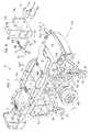
- FIG. 1is a perspective front end view of a prone cart with a body support having moveable sections.
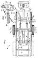
- FIG. 2is a side elevation of the prone cart illustrated in FIG. 1 with the body support in a lowered position.
- FIG. 3is a side elevation of the prone cart illustrated in FIG. 1 with the body support in the elevated position.
- FIG. 4is a schematic illustration of the relative movement of the various sections of the body support between the lowered position and the elevated position.
- FIG. 5is an illustration of one of a pair of cradles each of which independently supports a drive wheel and motor.
- FIG. 6is top plan view of the prone cart illustrated in FIG. 1 .
- FIG. 7is a bottom view of the prone cart illustrated in FIG. 1 .
- FIG. 8is a fragmentary illustration of a four bar linkage employed for controlling the orientation of a tray.
- FIG. 9is a fragmentary illustration of a foot support extending from an end of the body support.
- FIG. 10is an exploded perspective view of the tray forming a section of the body support.
- FIG. 11is an exploded perspective view of a chest support forming a section of the body support.
- FIG. 12is an exploded perspective view of an abdominal support forming a section of the body support.
- FIG. 13is an exploded perspective view of a leg support forming a section of the body support.
- FIGS. 1-3generally illustrate an exemplary embodiment of a prone cart 10 for supporting a patient on an body support 12 which has several moveable or articuable sections including a tray section 14 , a chest support section 16 , an abdominal support section 18 and a leg support section 20 with an attached foot support 21 extending therefrom.
- the sections of the body supportmay be selectively positioned in order to allow the patient to be supported in various prone positions between a lower or fully horizontal prone position 22 ( FIG. 2 ) to an elevated or raised position 23 ( FIG. 3 .)
- the tray support section 14has a front end 14 F and a rear end 14 R; the chest support section 16 has a front end 16 F pivotally connected to the rear end 14 R of the tray section 14 and a rear end 16 R.
- the abdominal support section 18has a front-end 18 F pivotally connected to the rear end 16 R of the chest support and a rear end 18 R.
- Leg support section 20has a front-end 20 F pivotally connected to the rear end 18 R of the chest support and a rear end 20 R.
- the foot support 21has a front-end 21 F telescopically coupled to the rear end 20 R of the leg support section and a free rear end 21 R.
- the patientlies fully flat, and in FIG. 3 the patient (not shown) is supported so that the head and chest are raised and the abdomen and legs of the patient are lowered, thereby allowing the patient to be more comfortably positioned when the cart 10 is maneuvered about.
- the patientmay adjust the position of the body support 12 between the fully prone position 22 and the elevated position 23 as desired.
- the body supportis generally horizontal.
- the tray section 14 and chest support section 16are elevated above the horizontal and the abdominal support section 18 and leg support section 20 are lowered relative to the horizontal.
- the chest support section 16 , the abdominal support section 18 and the leg support section 20each have a corresponding safety belt 24 , 25 and 26 for safely securing the patient to the body support.
- the cart 10has a frame 30 carried by front and rear wheels 32 and 33 positioned respectively at the corresponding front corners 38 and rear corners 38 thereof.
- the wheels 32 and 33are mounted for rotation about a respective corresponding horizontal axis 34 and 35 for forward and rearward motion; and the wheels 32 - 33 are each attached to the frame 10 about a corresponding vertical axis 36 - 37 allowing the wheels to swivel 3600 thereabout for turning the cart.
- the frame 30includes side members 38 and cross members 40 joining the side members in parallel alignment as shown.
- various components of the body support, and various mechanical componentsare carried by the frame.
- the body support 12is pivotally secured to the frame by a main support or bearing 42 located between the rear end 16 R of the chest support and the front-end 18 F of the abdominal support.
- the body support 12moves between the prone position 22 ( FIG. 2 ) and the raised position 23 ( FIG. 3 ) about the main bearing.
- a pair of drive wheels 48are positioned, as shown, more or less centrally of the frame 30 .
- Each wheel 48has a horizontal axis of rotation 50 and is connected to a corresponding electric drive motor 52 powered by a storage battery 54 carried by an independent suspension or cradle 56 .
- Each cradle 56has a pair of lower bearings 58 secured to a lower cross member 60 which is in turn secured to the side members 44 of the frame 30 .
- the bearings 58lie on a common horizontal lower axis 62 .
- the cradle 56has an upper bearing 64 coupled to upper cross member 66 by a spring loaded damper or shock absorber 68 which expands and contracts along upper axis 70 .
- a free end of the shock absorber 68is rotatably coupled to the upper cross member by bearing 72 .
- the cradle 56rotates about the lower axis 62 as the shock absorber takes up motion between the upper bearing 64 and the upper cross member 66 .
- the cradle 56is positioned forward of the centrally located wheels.
- the cradlesseparately support each drive wheel 48 and drive motor 52 , and thus each drive wheel 48 engages the ground independently, such that the corresponding rotational horizontal axis 50 is separately moveable upwardly and downwardly about the lower axis 62 . In this way, as each wheel engages the ground it moves separately and independently from the other such that the frame remains generally unaffected by irregularities in the ground surface.
- the frameis formed of tubular elements and has open areas 64 .
- the open areasreceive contoured transparent plastic sheets 66 which cover the openings but allow the mechanism to be visible.
- the transparent sheets 66are held in position by clips 68 attached to the tubular parts of the frame as shown.
- the rear end 16 R of the chest supportrotates about a pivot axis 72 , coaxial with the main bearing 42 , between the prone or horizontal position 22 upwardly to the elevated position 23 .
- the front end 18 F of the abdominal support 18rotates about the pivot axis 74 A between prone position 21 downwardly as the chest support section 14 moves upwardly.
- the leg support 20has a front end 90 secured to the rear end 82 of the abdominal support 18 and a rear end 92 extending rearwardly of the frame as shown.
- the foot support 22has a front end 94 secured to the rear end 82 of the leg support 20 .
- the leg support 20moves with the abdominal support 18 .
- FIGS. 1 and 3show the body support 12 in the raised position 23 and the lowered position 22 respectively.
- the sections of the body supportare generally aligned along a horizontal plane.
- the body supportis in the raised position 24 , which is to say that the body support in inclined with the tray 14 and chest support 16 raised above the horizontal and the abdominal support 18 and foot support 20 lowered below the horizontal as shown.
- FIG. 4schematically illustrates the positioning of the various sections of the body support 12 between the raised and lowered positions.
- the chest support 16moves between the horizontal and the raised or inclined upper position about the pivot 72 .
- the section 14is carried from the lower position upwardly to the raised position as shown.
- the tray section 14remains horizontal as it moves between the lower and upper positions.
- the abdominal support 18moves downwardly from the horizontal position when the chest support and tray move up.
- the leg support 20moves down with the abdominal support.
- the leg supportdoes not remain horizontal throughout its range of motion, but first moves with the abdominal support until its free or rear end 20 R engages a stop 74 on the frame 30 whereupon the leg support comes to rest in the horizontal position.
- each of the sections of the body support 12have an underlying support frame or deck member.
- the tray section 14has a tray deck 80 , a tray 82 carried by the tray deck 80 and a storage bin 84 supported by the deck 80 below the tray 82 .
- the trayis slidably mounted to the deck 82 so that the patient may push the tray forward to reveal access to the bin 84 . In this way, the position of the patient relative to the bin does not change when the bin is accessed, thereby adding a measure of comfort and convenience for the patient.
- the chest support 16has a chest support deck 90 carrying a shaped chest cushion 92 secured in overlying relation thereto.
- the abdominal support 18has an abdominal support deck 100 carrying a shaped abdominal cushion 102 secured thereto in overlying relation thereto.
- the leg support section 20has a leg support deck 110 carrying a shaped leg cushion 112 secured thereto in overlying relation therewith.
- the chest support deck 100 and the leg support deck 110are pivotally connected by bearing 114 establishing an axis of rotation 116 about which the sections rotate.
- the leg support deck 110is secured below the chest support deck 100 .
- the abdominal support deck 100has rear extensions 104 which engage the forward end of the leg support deck.
- the leg support deck 110has a forward extension 118 extending forwardly of the bearing 116 and having an outboard or free end 120 and a distal or inboard end 122 .
- the forward extension 118normally engages the underside of the abdominal support deck 100 when the body support 12 is in the prone position 22 , such that, the leg support deck 110 is maintained in alignment as a cantilever extending from the rear end 100 R of the chest support deck 100 as it is lowered when the body support is itself lifted to the raised position.
- the leg support deck 100is positioned below and overlaps with the abdominal support deck 110 .
- the extension 118acts as a cantilever for carrying the leg support.
- the extension 118engages the underside of the abdominal support deck 100 such that the leg support deck 110 is held horizontally and in alignment with the abdominal support as shown in FIG. 2 .
- the frame 30has a pair of stops 74 mounted inwardly for engaging the underside of the leg support deck 110 near the rear end 20 R of the leg support section 20 . As the leg support section 20 moves downwardly the frame 118 engages the stops 74 whereby the leg support section rotates relative to the abdominal support 18 .
- the abdominal support section 18moves downwardly to a point where its rear end 18 R is more or less aligned horizontally with respect to the stops 74 . Accordingly, the leg support comes to rest in the horizontal position when the abdominal support comes to rest at the end of its downward motion.
- the position of the stopsmay be changed or adjusted so that the leg support may come to rest in a different orientation as desired.
- the rear extensions 104 of the chest support deck and the forward extensions 118 of the leg support deckcooperate to lift the leg support and allow it to articulate to the horizontal rest position when it engages the stops 74 .
- the leg support deck 110has a rear or free end 124 . As shown in FIGS. 2 and 3 , the leg support deck is free to rotate upwardly (counter clockwise) as it moves downwardly from the prone position 22 ( FIG. 2 ) with the abdominal support deck 100 as the body support 12 is raised or lifted to the elevated position 23 ( FIG. 3 ). As the leg support deck 110 moves with the abdominal support deck 100 , the free end 124 moves downwardly and engages the frame stops 74 . As a result, the leg support deck 110 rotates upwardly or counterclockwise with respect to the abdominal support deck 100 . When the latter comes to rest, the leg support likewise comes to rest at a generally horizontal orientation, as shown in FIG. 3 .
- FIGS. 2 and 3illustrate components for raising and lowering the body support 12 .
- a lift motor or actuator 126is mounted to an intermediate cross member 128 connected between the sides 44 below and forwardly of the bearings 58 .
- the motor or actuator 126has a telescopic screw drive 130 connected thereto which extends towards and is pivotally coupled to the underside of the chest support deck 100 .
- the screw drive 130extends between a retracted position, shown in FIG. 2 when the body support is in the lower or prone position 22 , to an extended position, shown in FIG. 3 when the body support is in the raised position 23 .
- the motor or actuator 126activates the screw drive 130 which telescopes upwardly driving the chest support deck 100 upwardly about the axis 74 A.
- the rear end 14 R of the tray section 14is secured to the front end 16 F of the chest support section 16 .
- the tray support deck 80has a pair of lateral bearings 134 connected to corresponding lateral bearings on the chest support deck 90 . As the front end 16 F of the chest support deck 90 16 is raised, the rear end 14 R of the tray deck 80 is raised.
- the tray support section 14remains horizontal as it moves up and down. This is necessary because the patient is likely to carry personal items on the tray 82 or in the drawer below, and it is not desirable for the tray to tilt as the tray 82 is raised and lowered as such personal objects may slide or fall of the tray. Accordingly, as shown in FIG. 8 , the tray section 14 is equipped with a four bar linkage 140 for maintaining the tray support deck 80 in a horizontal orientation.
- the four bar linkage 140includes a pair of elongated upper and lower parallel bars 144 - 145 which extend generally lengthwise of the chest support section 16 ; and a pair of relatively short forward and rearward parallel vertical bars 146 - 147 which extend downwardly from the underside of chest support deck 90 .
- the upper bar 144is an integral part of the chest support deck 90 and moves with it.
- the rearward bar 147extends downwardly from the main bearing 42 which rotates about axis 74 A.
- the rearward bar 147has an upper end 148 fixedly attached to the frame 30 for maintaining the rear bar in a fixed vertical position and extending downwardly from the bearing 42 .
- the upper end 149 of forward bar 146is rotatably secured to the tray support deck 80 at the forward end 16 F of the tray support deck 90 , and the bar 146 has a free lower end 150 .
- the lower bar 145is connected between the lower end 152 of the rear bar 145 and the lower end 150 of the forward bar 146 .
- the forward bar 146has a forwardly extending leg 154 which is fixedly secured to or is an integral part of the tray support deck 80 .
- the chest support deck 90carries the four bar linkage 140 up and down as it is driven by the motor or actuator 120 and screw drive 122 .
- the forward bar 146remains vertical it moves up and down, because the lower bar 145 establishes a rotational radius extending between the lower end 152 of the rear bar 147 to the lower end 150 of the forward bar 146 .
- the forwardly extending leg 154 secured to or integral with forward bar 146remains in the horizontal position as the forward bar moves up and down.
- the four bar linkage 140thereby maintains the tray section 14 in a horizontal orientation as the tray moves between the lower and raised positions.
- the various sections of the body supportmove in a coordinated fashion.
- the chest support sectionmoves up and down with the motor.
- the tray sectionmoves with the chest support section.
- the abdominal supportmoves with the tray section and the leg support moves with the chest support section.
- a rocker beam 160is rotatably secured to a bearing 162 fixed to the frame 30 below the pivot axis 74 A.
- the beam 160has a forward end 164 and a rearward end 166 .
- the forward end 162 of the beam 160is pivotally secured to the underside to of the chest support deck 90 by an interconnecting linkage 168 .
- the forward end 164 of the beam 160rotates upwardly.
- the rear end 166 of the beam 160is coupled to a linkage 170 having a proximate end 172 pivotally connected thereto and a distal end 174 slideably connected to a slotted member 176 secured to the underside of the leg support deck 110 .
- the slotted member 176has an elongated slot 178 extending longitudinally of the leg support deck 110 .
- the abdominal support deck 100is linked to the tray support deck 80 by a linkage mechanism 180 which causes the abdominal support deck 100 to rotate in the downward direction when the tray deck 80 moves upwardly.
- a linkage mechanism 180which causes the abdominal support deck 100 to rotate in the downward direction when the tray deck 80 moves upwardly.
- the linkage mechanism 180 connecting the tray support deck 80 and the abdominal support deck 100includes first, second, third and fourth links 182 , 184 , 186 , 188 .
- the first link 182has a proximate end 190 pivotally connected to the underside of the tray support deck 80 and a distal end 192 pivotally connected to a distal end 194 of the second link 184 .
- the second link 184has a proximal end 196 pivotally connected to the frame 30 .
- the third link 186has a forward end 198 connected to the second link 184 intermediate the ends thereof.
- the third link 186has a rearward end 200 connected to a distal end 204 of the fourth link 188 , which in turn has a proximal end 206 fixedly connected to the underside of the abdominal support deck 100 .
- the second link 184rotates about the proximal end 190 .
- the third link 186driven by the second link thus moves the abdominal support deck 100 down as the tray support deck 80 moves up and vice versa.
- the leg support moving with itlikewise moves up and down.
- the linkage 170 connected between the rear end 164 of the beam 160 and the slotted member 176guides the leg support section 20 as it moves towards the stops 150 .
- FIG. 9illustrates the foot support 21 which includes a housing 210 in the form of an open container having a front wall 212 , a rear or bottom wall 214 , lateral side walls 216 , a pair or proximate intermediate walls 218 and toe walls 220 forming a left and right compartment 221 - 222 for receiving the corresponding left and right foot of the patient (not shown).
- a housing 210in the form of an open container having a front wall 212 , a rear or bottom wall 214 , lateral side walls 216 , a pair or proximate intermediate walls 218 and toe walls 220 forming a left and right compartment 221 - 222 for receiving the corresponding left and right foot of the patient (not shown).
- a housing 210in the form of an open container having a front wall 212 , a rear or bottom wall 214 , lateral side walls 216 , a pair or proximate intermediate walls 218 and toe walls 220 forming a left and right compartment
- the housing 210is adjustable about a horizontal axis 224 which is disposed transverse to the longitudinal axis 226 of the body support 12 .
- An apertured disk 228is secured to the housing between the proximate intermediate walls.
- a forwardly extending support 230is connected to the disk 228 by a removable pin 232 .
- the support 230is fixed to the rear end of the leg support by an adjustable telescopic pin 234 .
- the relative position of the foot housing with respect to the leg supportmay be adjusted longitudinally by the telescopic pin, and the rotational aspect of the housing may be adjusted by rotating the disk with respect to the pin and inserting clips or pins to secure the housing from rotation as the correct and comfortable position of the housing is determined.
- the controller 240is coupled to the electric drive motors 52 which drive the wheels 48 and which in turn are powered by the rechargeable batteries 54 .
- a joystick 244is mounted on the tray section 14 at a convenient location for use by the patient. The joystick controls forward, reverse, left and right operation of the cart by selectively powering the left and right drive motors, which in turn rotate the wheels in forward and reverse directions.
- the drive wheelsmay operate in the same or opposite sense for facilitating tight control of the cart. For example if the patient is in a congested corridor or if the patient enters a small furnished room, it is possible for the patient to easily maneuver the cart in and around the obstacles in such a corridor or room. This is because the wheels are positioned on an axis 246 located more or less midway along the longitudinal axis 248 of the cart. As a result, the cart can rotate 360° about such axis, with a resulting zero turning radius. In addition, left and right control of the cart is facilitated by independent control of the motor direction as well.
- a separate control or joystick 250may be coupled to the controller 240 , batteries 54 , and reversible lift motor 128 for raising and lowering the body support.
- a single joystickmay be employed for combining the various functions.
- the controller, joystick and reversible drive and lift motorsare known devices available in the market.
- the various linkages described hereinmay have bearings which are adjustable.
- the third link 186 in the linkage mechanism 180may have ends which carry bearings mounted to a machine screw.
- the ends of the link 186 , and other linkages in the cartmay be extended or adjusted for optimum performance.
- the cushions 92 , 102 and 112are each formed with a 20 mm (3 ⁇ 4′′) plywood base 200 , with t-nut fasteners 202 .
- Urethane 65 IFD foam padding 204overlies the base.
- the paddinghas a central area 206 thickness of 50 mm and side bolsters 208 having a thickness of about 75 mm.
- a visco-elastic memory foam topper 212overlies the padding 204 .
- a vinyl cover 214cut and sewn to shape overlies the topper and is attached to the base to enclose the cushion materials.
Landscapes
- Health & Medical Sciences (AREA)
- Life Sciences & Earth Sciences (AREA)
- Animal Behavior & Ethology (AREA)
- General Health & Medical Sciences (AREA)
- Public Health (AREA)
- Veterinary Medicine (AREA)
- Handcart (AREA)
- Accommodation For Nursing Or Treatment Tables (AREA)
Abstract
Description
Claims (21)
Priority Applications (1)
| Application Number | Priority Date | Filing Date | Title |
|---|---|---|---|
| US12/134,147US7690057B2 (en) | 2007-06-08 | 2008-06-05 | Folding frame motorized prone cart |
Applications Claiming Priority (2)
| Application Number | Priority Date | Filing Date | Title |
|---|---|---|---|
| US93390307P | 2007-06-08 | 2007-06-08 | |
| US12/134,147US7690057B2 (en) | 2007-06-08 | 2008-06-05 | Folding frame motorized prone cart |
Publications (2)
| Publication Number | Publication Date |
|---|---|
| US20080301875A1 US20080301875A1 (en) | 2008-12-11 |
| US7690057B2true US7690057B2 (en) | 2010-04-06 |
Family
ID=40094477
Family Applications (1)
| Application Number | Title | Priority Date | Filing Date |
|---|---|---|---|
| US12/134,147Expired - Fee RelatedUS7690057B2 (en) | 2007-06-08 | 2008-06-05 | Folding frame motorized prone cart |
Country Status (1)
| Country | Link |
|---|---|
| US (1) | US7690057B2 (en) |
Cited By (9)
| Publication number | Priority date | Publication date | Assignee | Title |
|---|---|---|---|---|
| US20120117730A1 (en)* | 2006-06-28 | 2012-05-17 | Stryker Corporation | Patient support with wireless data and/or energy transfer |
| WO2012114332A1 (en)* | 2011-02-22 | 2012-08-30 | Rani Meiki | Articulated therapeutic apparatus and method |
| US20130125310A1 (en)* | 2008-07-09 | 2013-05-23 | Piedmont 361, Llc | Hospital chair beds with drop foot section |
| US20140023469A1 (en)* | 2009-10-02 | 2014-01-23 | Stryker Corporation | Ambulance cot and loading and unloading system |
| US20150320624A1 (en)* | 2014-05-12 | 2015-11-12 | Lynda Woodman | Prone cart |
| US20170020752A1 (en)* | 2015-07-24 | 2017-01-26 | Stryker Corporation | System and method of braking for a patient support apparatus |
| US9603764B2 (en) | 2014-02-11 | 2017-03-28 | Medline Industries, Inc. | Method and apparatus for a locking caster |
| US9932081B2 (en) | 2013-12-05 | 2018-04-03 | Milsco Manufacturing Company, A Unit Of Jason Incorporated | Composite fiber saddlebag, saddle bag liner, and method |
| US10376433B2 (en)* | 2017-04-15 | 2019-08-13 | Dk City Corporation | Electrically adjustable bed |
Families Citing this family (11)
| Publication number | Priority date | Publication date | Assignee | Title |
|---|---|---|---|---|
| US7321811B1 (en) | 2006-09-14 | 2008-01-22 | Rawls-Meehan Martin B | Methods and systems of adjustable bed position control |
| US8926535B2 (en) | 2006-09-14 | 2015-01-06 | Martin B. Rawls-Meehan | Adjustable bed position control |
| US10064784B2 (en) | 2006-09-14 | 2018-09-04 | Martin B. Rawls-Meehan | System and method of an adjustable bed with a vibration motor |
| US10864137B2 (en) | 2006-09-14 | 2020-12-15 | Ascion, Llc | System and method of an adjustable bed with a vibration motor |
| US7690057B2 (en)* | 2007-06-08 | 2010-04-06 | The United States Of America As Represented By The Department Of Veterans Affairs | Folding frame motorized prone cart |
| US20100037397A1 (en)* | 2008-08-14 | 2010-02-18 | RemGenic LLC | Bed |
| US20120280464A1 (en)* | 2008-10-27 | 2012-11-08 | Nelson Richard L | Adjustable load-bearing wheels and kits for patient lifters |
| CN103720552A (en)* | 2014-01-10 | 2014-04-16 | 山东省肿瘤防治研究院 | Multifunctional medical care bed |
| CN108882796A (en)* | 2016-03-29 | 2018-11-23 | 斯堪的那维亚本土仿生公司 | Body support |
| CN110025433B (en)* | 2019-05-28 | 2020-12-22 | 河南科技大学第一附属医院 | A cardiovascular medical examination device |
| US11826589B2 (en)* | 2021-10-05 | 2023-11-28 | Charles J. Mackarvich | Balance mobile anchor cart |
Citations (26)
| Publication number | Priority date | Publication date | Assignee | Title |
|---|---|---|---|---|
| US782335A (en)* | 1904-03-17 | 1905-02-14 | Peter H Benjamin | Adjustable chair. |
| US847619A (en)* | 1906-09-29 | 1907-03-19 | Aiken C Taylor | Invalid-bed. |
| US923729A (en)* | 1908-09-22 | 1909-06-01 | Aiken C Taylor | Invalid-bed. |
| US1243887A (en)* | 1915-07-06 | 1917-10-23 | Owens Stark Mfg Company | Adjustable bed-spring for beds, davenports, couches, and the like. |
| US1261040A (en)* | 1917-04-19 | 1918-04-02 | Samuel Lanes | Combined chair and bed. |
| US1297683A (en)* | 1917-10-18 | 1919-03-18 | Edward Hansen | Combination chair and bed. |
| US1617108A (en)* | 1924-09-22 | 1927-02-08 | Gursky Max | Chair bed |
| US1748784A (en)* | 1928-02-13 | 1930-02-25 | Ida B Mierley | Physical and surgical apparatus |
| US2578311A (en)* | 1946-01-12 | 1951-12-11 | Lorenz Anton | Reclining article of furniture |
| US3003160A (en)* | 1958-12-01 | 1961-10-10 | Goodman Robert | Foldable bed frame-bed to contour chair |
| US3010121A (en)* | 1957-04-12 | 1961-11-28 | Roy Frederick Thompson | Adjustable support device |
| US3839755A (en) | 1973-01-03 | 1974-10-08 | A Iannucci | Mobile bed for the handicapped |
| US4099277A (en) | 1975-09-30 | 1978-07-11 | Watkins Mervyn M | Stander apparatus providing varying degrees of weight bearing for patient therapy |
| US4821351A (en)* | 1986-08-27 | 1989-04-18 | Molnlycke Ab | Bed and/or chair device |
| US5072463A (en)* | 1991-04-11 | 1991-12-17 | Willis William J | EZ access bed |
| EP0596115A1 (en)* | 1992-05-22 | 1994-05-11 | IURA, Tadashi | Rotary bed |
| US5418988A (en)* | 1989-06-26 | 1995-05-30 | Iura; Tadashi | Rotary bed with inwardly pivotable handrails |
| US5634221A (en) | 1996-03-15 | 1997-06-03 | Mckinney; Michael L. | Prone cart |
| US5868461A (en)* | 1997-05-06 | 1999-02-09 | Broda Enterprises Inc. | Reclining chair |
| US6154899A (en)* | 1998-10-19 | 2000-12-05 | Hill-Rom, Inc. | Resident transfer chair |
| US6230346B1 (en)* | 1999-06-10 | 2001-05-15 | Basic American Medical Products, Inc. | Articulated bed incorporating a single motor drive mechanism |
| US20010008028A1 (en)* | 1997-04-11 | 2001-07-19 | Jerry Blevins | Patient bed with leg lifter |
| US6381781B1 (en)* | 1999-08-24 | 2002-05-07 | Ferno-Washington, Inc. | Combination ambulance cot and chair |
| US6427270B1 (en)* | 1997-04-11 | 2002-08-06 | Jerry L. Blevins | Cantilevered mobile bed/chair apparatus for safety patient transfer |
| US20060218724A1 (en)* | 2005-04-01 | 2006-10-05 | Jerry Blevins | Bed having tiltable section |
| US20080301875A1 (en)* | 2007-06-08 | 2008-12-11 | Pascal Malassigne | Folding frame motorized prone cart |
- 2008
- 2008-06-05USUS12/134,147patent/US7690057B2/ennot_activeExpired - Fee Related
Patent Citations (32)
| Publication number | Priority date | Publication date | Assignee | Title |
|---|---|---|---|---|
| US782335A (en)* | 1904-03-17 | 1905-02-14 | Peter H Benjamin | Adjustable chair. |
| US847619A (en)* | 1906-09-29 | 1907-03-19 | Aiken C Taylor | Invalid-bed. |
| US923729A (en)* | 1908-09-22 | 1909-06-01 | Aiken C Taylor | Invalid-bed. |
| US1243887A (en)* | 1915-07-06 | 1917-10-23 | Owens Stark Mfg Company | Adjustable bed-spring for beds, davenports, couches, and the like. |
| US1261040A (en)* | 1917-04-19 | 1918-04-02 | Samuel Lanes | Combined chair and bed. |
| US1297683A (en)* | 1917-10-18 | 1919-03-18 | Edward Hansen | Combination chair and bed. |
| US1617108A (en)* | 1924-09-22 | 1927-02-08 | Gursky Max | Chair bed |
| US1748784A (en)* | 1928-02-13 | 1930-02-25 | Ida B Mierley | Physical and surgical apparatus |
| US2578311A (en)* | 1946-01-12 | 1951-12-11 | Lorenz Anton | Reclining article of furniture |
| US3010121A (en)* | 1957-04-12 | 1961-11-28 | Roy Frederick Thompson | Adjustable support device |
| US3003160A (en)* | 1958-12-01 | 1961-10-10 | Goodman Robert | Foldable bed frame-bed to contour chair |
| US3839755A (en) | 1973-01-03 | 1974-10-08 | A Iannucci | Mobile bed for the handicapped |
| US4099277A (en) | 1975-09-30 | 1978-07-11 | Watkins Mervyn M | Stander apparatus providing varying degrees of weight bearing for patient therapy |
| US4821351A (en)* | 1986-08-27 | 1989-04-18 | Molnlycke Ab | Bed and/or chair device |
| US5418988A (en)* | 1989-06-26 | 1995-05-30 | Iura; Tadashi | Rotary bed with inwardly pivotable handrails |
| US5425151A (en)* | 1989-06-26 | 1995-06-20 | Iura; Tadashi | Rotary, invalid bed |
| US5444883A (en)* | 1989-06-26 | 1995-08-29 | Iura; Tadashi | Rotary, invalid bed |
| US5072463A (en)* | 1991-04-11 | 1991-12-17 | Willis William J | EZ access bed |
| EP0596115A1 (en)* | 1992-05-22 | 1994-05-11 | IURA, Tadashi | Rotary bed |
| US5497518A (en)* | 1992-05-22 | 1996-03-12 | Iura; Tadashi | Rotary bed |
| US5634221A (en) | 1996-03-15 | 1997-06-03 | Mckinney; Michael L. | Prone cart |
| US6427270B1 (en)* | 1997-04-11 | 2002-08-06 | Jerry L. Blevins | Cantilevered mobile bed/chair apparatus for safety patient transfer |
| US20010008028A1 (en)* | 1997-04-11 | 2001-07-19 | Jerry Blevins | Patient bed with leg lifter |
| US6691349B2 (en)* | 1997-04-11 | 2004-02-17 | Jerry Blevins | Patient bed with leg lifter |
| US20040154097A1 (en)* | 1997-04-11 | 2004-08-12 | Jerry Blevins | Patient bed with leg lifter |
| US5868461A (en)* | 1997-05-06 | 1999-02-09 | Broda Enterprises Inc. | Reclining chair |
| US6154899A (en)* | 1998-10-19 | 2000-12-05 | Hill-Rom, Inc. | Resident transfer chair |
| US6185769B1 (en)* | 1998-10-19 | 2001-02-13 | Hill-Rom, Inc. | Resident transfer chair |
| US6230346B1 (en)* | 1999-06-10 | 2001-05-15 | Basic American Medical Products, Inc. | Articulated bed incorporating a single motor drive mechanism |
| US6381781B1 (en)* | 1999-08-24 | 2002-05-07 | Ferno-Washington, Inc. | Combination ambulance cot and chair |
| US20060218724A1 (en)* | 2005-04-01 | 2006-10-05 | Jerry Blevins | Bed having tiltable section |
| US20080301875A1 (en)* | 2007-06-08 | 2008-12-11 | Pascal Malassigne | Folding frame motorized prone cart |
Non-Patent Citations (1)
| Title |
|---|
| Material Supplied by Inventors Showing Devices Known to Them (Undated). |
Cited By (25)
| Publication number | Priority date | Publication date | Assignee | Title |
|---|---|---|---|---|
| US10561551B2 (en) | 2006-06-28 | 2020-02-18 | Stryker Corporation | Patient support with energy transfer |
| US12383450B2 (en) | 2006-06-28 | 2025-08-12 | Stryker Corporation | Patient support with energy transfer |
| US11793699B2 (en) | 2006-06-28 | 2023-10-24 | Stryker Corporation | Patient support with energy transfer |
| US20120117730A1 (en)* | 2006-06-28 | 2012-05-17 | Stryker Corporation | Patient support with wireless data and/or energy transfer |
| US8864205B2 (en)* | 2006-06-28 | 2014-10-21 | Stryker Corporation | Patient support with wireless data and/or energy transfer |
| US20130125310A1 (en)* | 2008-07-09 | 2013-05-23 | Piedmont 361, Llc | Hospital chair beds with drop foot section |
| US10806647B2 (en) | 2009-10-02 | 2020-10-20 | Stryker Corporation | Ambulance cot and loading and unloading system |
| US10149791B2 (en) | 2009-10-02 | 2018-12-11 | Stryker Corporation | Ambulance cot and loading and unloading system |
| US12357518B2 (en) | 2009-10-02 | 2025-07-15 | Stryker Corporation | Ambulance cot and loading and unloading system |
| US20140023469A1 (en)* | 2009-10-02 | 2014-01-23 | Stryker Corporation | Ambulance cot and loading and unloading system |
| US9456939B2 (en) | 2009-10-02 | 2016-10-04 | Stryker Corporation | Ambulance cot and loading and unloading system |
| US8973963B2 (en)* | 2009-10-02 | 2015-03-10 | Stryker Corporation | Ambulance cot and loading and unloading system |
| WO2012114332A1 (en)* | 2011-02-22 | 2012-08-30 | Rani Meiki | Articulated therapeutic apparatus and method |
| US20130307298A1 (en)* | 2011-02-22 | 2013-11-21 | Rani Meiki | Articulated therapeutic apparatus and method |
| US9205008B2 (en)* | 2011-02-22 | 2015-12-08 | Rani Meiki | Articulated therapeutic apparatus and method |
| US9932081B2 (en) | 2013-12-05 | 2018-04-03 | Milsco Manufacturing Company, A Unit Of Jason Incorporated | Composite fiber saddlebag, saddle bag liner, and method |
| US9993378B2 (en) | 2014-02-11 | 2018-06-12 | Medline Industries, Inc. | Method and apparatus for a locking caster |
| US9603764B2 (en) | 2014-02-11 | 2017-03-28 | Medline Industries, Inc. | Method and apparatus for a locking caster |
| US20150320624A1 (en)* | 2014-05-12 | 2015-11-12 | Lynda Woodman | Prone cart |
| US9402773B2 (en)* | 2014-05-12 | 2016-08-02 | Gillette Children's Specialty Healthcare | Prone cart |
| US20170020752A1 (en)* | 2015-07-24 | 2017-01-26 | Stryker Corporation | System and method of braking for a patient support apparatus |
| US11497664B2 (en) | 2015-07-24 | 2022-11-15 | Stryker Corporation | System and method of braking for a patient support apparatus |
| US11963910B2 (en) | 2015-07-24 | 2024-04-23 | Stryker Corporation | System and method of braking for a patient support apparatus |
| US10912685B2 (en)* | 2015-07-24 | 2021-02-09 | Stryker Corporation | System and method of braking for a patient support apparatus |
| US10376433B2 (en)* | 2017-04-15 | 2019-08-13 | Dk City Corporation | Electrically adjustable bed |
Also Published As
| Publication number | Publication date |
|---|---|
| US20080301875A1 (en) | 2008-12-11 |
Similar Documents
| Publication | Publication Date | Title |
|---|---|---|
| US7690057B2 (en) | Folding frame motorized prone cart | |
| US11058593B2 (en) | Mobility device for physically disabled people | |
| US4255823A (en) | Apparatus for moving and/or transporting loads | |
| US8516637B2 (en) | Patient care and transport assembly | |
| US5096008A (en) | Stand-up wheelchair | |
| EP0907343B1 (en) | Support unit | |
| US6540250B1 (en) | Height adjustable wheelchair | |
| US5366036A (en) | Power stand-up and reclining wheelchair | |
| US6425635B1 (en) | Weight-shifting reclining and tilting wheelchair seat | |
| US6092247A (en) | Powered patient lift vehicle | |
| US7419019B1 (en) | Power assist apparatus for use with a hospital bed | |
| US6276704B1 (en) | Adjustable wheelchair having a tilting and reclining seat | |
| US5193633A (en) | Motorized transfer and transport system for the disabled | |
| US5072463A (en) | EZ access bed | |
| JP6711959B2 (en) | Low mobility human stretcher | |
| US6691348B2 (en) | Bed with adjustable positions | |
| US5860664A (en) | Combination wheelchair sleeper 24-hour use apparatus | |
| US20130212807A1 (en) | Bed chair | |
| KR101878410B1 (en) | Method of keeping it horizontal position for stretcher cart | |
| US11806290B2 (en) | Adjustable patient support apparatus for assisted egress and ingress | |
| CA3014158A1 (en) | Configurable assistive device | |
| US10842692B2 (en) | Elevatable and portable wheelchair | |
| US20240269019A1 (en) | Patient Transport Apparatus With Stowable Footrest | |
| CN114980849B (en) | Adjustment device for transport seats | |
| CN112168507A (en) | A foldable transfer medical bed |
Legal Events
| Date | Code | Title | Description |
|---|---|---|---|
| AS | Assignment | Owner name:DEPARTMENT OF VETERANS AFFAIRS, DISTRICT OF COLUMB Free format text:ASSIGNMENT OF ASSIGNORS INTEREST;ASSIGNORS:MALASSIGNE, PASCAL;HARROW, JEFFREY;JENSEN, ROBERT;AND OTHERS;REEL/FRAME:021278/0326;SIGNING DATES FROM 20080707 TO 20080714 Owner name:MEDICAL CENTER OF WISCONSIN, WISCONSIN Free format text:ASSIGNMENT OF ASSIGNORS INTEREST;ASSIGNORS:MALASSIGNE, PASCAL;HARROW, JEFFREY;JENSEN, ROBERT;AND OTHERS;REEL/FRAME:021278/0326;SIGNING DATES FROM 20080707 TO 20080714 Owner name:SOUTH FLORIDA, UNIVERSITY OF, FLORIDA Free format text:ASSIGNMENT OF ASSIGNORS INTEREST;ASSIGNORS:MALASSIGNE, PASCAL;HARROW, JEFFREY;JENSEN, ROBERT;AND OTHERS;REEL/FRAME:021278/0326;SIGNING DATES FROM 20080707 TO 20080714 Owner name:DEPARTMENT OF VETERANS AFFAIRS,DISTRICT OF COLUMBI Free format text:ASSIGNMENT OF ASSIGNORS INTEREST;ASSIGNORS:MALASSIGNE, PASCAL;HARROW, JEFFREY;JENSEN, ROBERT;AND OTHERS;SIGNING DATES FROM 20080707 TO 20080714;REEL/FRAME:021278/0326 Owner name:MEDICAL CENTER OF WISCONSIN,WISCONSIN Free format text:ASSIGNMENT OF ASSIGNORS INTEREST;ASSIGNORS:MALASSIGNE, PASCAL;HARROW, JEFFREY;JENSEN, ROBERT;AND OTHERS;SIGNING DATES FROM 20080707 TO 20080714;REEL/FRAME:021278/0326 Owner name:SOUTH FLORIDA, UNIVERSITY OF,FLORIDA Free format text:ASSIGNMENT OF ASSIGNORS INTEREST;ASSIGNORS:MALASSIGNE, PASCAL;HARROW, JEFFREY;JENSEN, ROBERT;AND OTHERS;SIGNING DATES FROM 20080707 TO 20080714;REEL/FRAME:021278/0326 | |
| STCF | Information on status: patent grant | Free format text:PATENTED CASE | |
| REMI | Maintenance fee reminder mailed | ||
| FPAY | Fee payment | Year of fee payment:4 | |
| SULP | Surcharge for late payment | ||
| MAFP | Maintenance fee payment | Free format text:PAYMENT OF MAINTENANCE FEE, 8TH YEAR, LARGE ENTITY (ORIGINAL EVENT CODE: M1552) Year of fee payment:8 | |
| FEPP | Fee payment procedure | Free format text:MAINTENANCE FEE REMINDER MAILED (ORIGINAL EVENT CODE: REM.); ENTITY STATUS OF PATENT OWNER: LARGE ENTITY | |
| LAPS | Lapse for failure to pay maintenance fees | Free format text:PATENT EXPIRED FOR FAILURE TO PAY MAINTENANCE FEES (ORIGINAL EVENT CODE: EXP.); ENTITY STATUS OF PATENT OWNER: LARGE ENTITY | |
| STCH | Information on status: patent discontinuation | Free format text:PATENT EXPIRED DUE TO NONPAYMENT OF MAINTENANCE FEES UNDER 37 CFR 1.362 | |
| FP | Lapsed due to failure to pay maintenance fee | Effective date:20220406 |