US7689762B2 - Storage device wear leveling - Google Patents
Storage device wear levelingDownload PDFInfo
- Publication number
- US7689762B2 US7689762B2US11/743,974US74397407AUS7689762B2US 7689762 B2US7689762 B2US 7689762B2US 74397407 AUS74397407 AUS 74397407AUS 7689762 B2US7689762 B2US 7689762B2
- Authority
- US
- United States
- Prior art keywords
- memory
- memory location
- address
- physical
- location
- Prior art date
- Legal status (The legal status is an assumption and is not a legal conclusion. Google has not performed a legal analysis and makes no representation as to the accuracy of the status listed.)
- Active, expires
Links
- 230000004044responseEffects0.000claimsabstractdescription9
- 238000000034methodMethods0.000claimsdescription52
- 238000012545processingMethods0.000claimsdescription13
- 239000000758substrateSubstances0.000claimsdescription4
- 230000008569processEffects0.000description34
- 238000010586diagramMethods0.000description18
- 238000013507mappingMethods0.000description13
- 238000004891communicationMethods0.000description9
- 238000013500data storageMethods0.000description5
- 230000004075alterationEffects0.000description1
- 230000000694effectsEffects0.000description1
- 230000006870functionEffects0.000description1
- 238000012986modificationMethods0.000description1
- 230000004048modificationEffects0.000description1
- 230000002028prematureEffects0.000description1
- 238000013519translationMethods0.000description1
Images


Classifications
- G—PHYSICS
- G11—INFORMATION STORAGE
- G11C—STATIC STORES
- G11C16/00—Erasable programmable read-only memories
- G11C16/02—Erasable programmable read-only memories electrically programmable
- G11C16/06—Auxiliary circuits, e.g. for writing into memory
- G11C16/34—Determination of programming status, e.g. threshold voltage, overprogramming or underprogramming, retention
- G11C16/349—Arrangements for evaluating degradation, retention or wearout, e.g. by counting erase cycles
Definitions
- This disclosurerelates to wear leveling.
- the memory cells of a memory devicecan eventually wear out from repeated programming and erasure.
- addressable sections of the memory devicecan be programmed and/or erased at similar rates by wear leveling.
- Wear levelingensures that the memory cells of the memory device wear evenly, e.g., programming and/or erasing of memory cells occurs at a similar rate for all the memory cells over the life of the memory device.
- Wear levelingtypically includes the swapping of data stored in memory locations that are infrequently changed with data stored in frequently changing memory locations, or the moving of data stored in memory blocks that are infrequently changed to unallocated memory blocks. The even wearing of the memory cells can thus prevent premature failure of the memory device.
- a reference memory locationcan be designated in a memory device, and a memory location can be identified in response to storing data in the memory device. If the identified memory location is associated with the reference memory location, then an allocated memory location relative to the reference memory location is identified, and the allocated memory location is leveled.
- a determinationcan be made as to whether to level an allocated memory location that is relative in a designated reference memory location. If the allocated memory location is determined to be leveled, then an unallocated memory location relative to the allocated memory location can be allocated to store data stored in the allocated memory location, and the allocated memory location can be deallocated. The designated reference memory location can be redesignated relative to the deallocated memory.
- a first allocated memory location relative to a reference memory locationcan be identified, and an unallocated memory location relative to the allocated memory location can also be identified.
- the unallocated memory locationcan be allocated to store data stored in the first allocated memory location, and the first allocated memory location can be deallocated.
- a memory location relative to the deallocated memory locationcan be identified, and the identified memory location can be designated as the reference memory location.
- a memory devicecan comprise a memory array comprising memory cells defining memory blocks and a memory driver configured to define a leveling locator and a free block locator.
- the memory drivercan also be configured to reference respective memory blocks indicated by the leveling locator and free block locator, and determine if the free block locator is associated with the leveling locator. Upon a positive determination, the memory driver can identify a utilized memory block respective to the leveling locator, and level the utilized memory block.
- FIG. 1is a block diagram of an example computer device.
- FIGS. 2-6are diagrams of a memory device architecture implementing wear leveling.
- FIG. 7is a flow diagram of an example process for wear leveling.
- FIG. 8is a flow diagram of an example process for leveling allocated memory.
- FIG. 10is a flow diagram of an example process for determining whether to wear level a memory location.
- FIG. 11is a flow diagram of another example process of wear leveling.
- FIG. 1is a block diagram of an example computer system 100 .
- the system 100can include a processor 102 , a data storage system 104 , and a communication system 108 .
- Each of the components 102 , 104 , and 108can, for example, be connected by a system bus 108 .
- the processor 102can process instructions stored in the data storage system 104 or received over the communication system 108 .
- Various different general purpose or special purpose computing system configurationscan be implemented as the computer system 100 , such as personal computers, server computers, hand-held or laptop devices, portable communication devices, programmable consumer electronics, gaming systems, multimedia systems, etc.
- the data storage system 104can, for example, include a volatile memory device, such as a random access memory (RAM), and/or can include a non-volatile memory device, such as a read only memory (ROM) and/or a flash memory. Other volatile and non-volatile memory devices can also be used.
- the data storage system 104can, for example, store an operating system and one or more application programs that can be executed by the processor 102 , and data associated with the operating system and/or the application programs.
- the communication system 106can transmit and receive data over a wired or wireless communication link.
- the communication subsystem 106can, for example, include communication devices that support one or more communication protocols, such as the Institute of Electrical and Electronics Engineer (IEEE) 802.x family of protocols (e.g., an Ethernet, a token ring, a wireless local area network, a wireless personal area network, etc.) or some other wired or wireless communication protocol.
- IEEEInstitute of Electrical and Electronics Engineer
- the data storage system 104can include a memory driver 110 and a non-volatile storage 112 , e.g., a flash memory device.
- the memory driver 110can, for example, include software and/or hardware to facilitate control of and access to the non-volatile storage 112 .
- the memory driver 110can, for example, utilize a logical-to-physical addressing translation for read and write operations.
- An example memory device architecture utilizing logical-to-physical mappingis shown and described with respect to FIG. 2 below.
- the memory driver 110 and the non-volatile storage 112can be integrated on the same substrate 114 or device. In another implementation, the memory driver 110 and the non-volatile storage 112 can be on separate substrates or devices, e.g., the memory driver 110 can be implemented in software and/or hardware within the computer system 100 , and separate from the substrate or device implementing the non-volatile storage 112 .
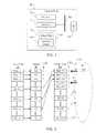
- FIG. 2is a block diagram of a memory device architecture 200 .
- the memory device architecture 200can include a logical array 220 , a logical-to-physical mapping array 240 , and a physical array 260 .
- the mapping array 240can define a mapping of logical addresses defined by the logical array 220 to the physical addresses defined by the physical array 260 .
- the mapping array 240can dynamically map m blocks of logical array 220 locations to n blocks of physical array 260 locations.
- m ⁇ nto ensure that unallocated memory locations for wear leveling are available in the physical array 260 .
- the physical array 260can be realized by a non-volatile memory device, e.g., a flash memory device.
- a non-volatile memory devicee.g., a flash memory device.
- Other memory devicescan also be used, however.
- the mapping array 240 and the physical array 260can have associated memory allocation flags 242 and 262 , respectively.
- the memory allocation flags 242 and 262can indicate, for example, whether the contents of each block associated with each memory allocation flag are valid, e.g., a currently allocated block for stored data, or invalid, e.g., a currently unallocated block that may contain expired data, erased data, or may otherwise be identified as an unallocated block of memory.
- the logical array 220is currently defining stored data in at least three addresses, e.g., blocks Lc, Ld and Le.
- the logical array 220 blocks Lc, Ld and Leare mapped to corresponding physical array 260 blocks P 0 , P 1 and P 2 , as defined by the mapping array 240 .
- Each of the physical array 260 blocks P 0 . P 1 and P 2store data represented by the abstracted data symbol d.
- the memory cells of a physical array 260can eventually wear out from repeated programming and erasure. Additionally, some blocks of the physical array 260 may not be programmed or erased very often, and thus other blocks of the physical array 260 are programmed and erased more often. To extend the overall life the physical array 260 , the blocks P 0 . . . Pn ⁇ 1 can be programmed and/or erased at similar rates by wear leveling. Wear leveling ensures that the blocks P 0 , . . . Pn ⁇ 1 wear evenly, e.g., programming and/or erasing of the blocks P 0 . . . Pn ⁇ 1 occurs at a similar rate for all the blocks over the lifetime of the physical array 260 .
- a reference memory locationcan be designated in the physical array 260 .
- the reference memory locationcan be designated by, for example, a leveling pointer LP that stores the location of the reference memory location, e.g. the address P 0 of block P 0 .
- Another identified memory locatione.g., a memory location currently eligible to receive data for storage, such as an unallocated memory location, can be designated in the physical array 260 .
- the identified memory locationcan, for example, be designated by a free block pointer FBP that stores the address of the identified memory location.
- the leveling pointer LP and the free block pointer FBPcan reference the same memory location, e.g., block P 0 in the physical array 260 .
- the dataare stored beginning at the memory block referenced by the free block pointer FBP.
- the free block pointer FBPis incremented to identify the next memory location eligible to receive data for storage. For example, as shown in FIG. 2 , after an initialization, data d are written to logical addresses defined by address blocks Lc, Ld and Le in the logical array 220 .
- a first write operationstores data at the logical address Le; because the free block pointer FBP references memory block P 0 in the physical array for the first write operation, the data are stored in the physical array at block P 0 , as indicated by the label “Block P 0 :d.”
- the mapping table 240stores the address of block P 0 in a table entry associated with the logical address Le, and the corresponding memory allocation flags 242 and 262 for the mapping table 240 and the physical array 260 are set to 1, respectively.
- the free block pointer FBPcan be incremented to the next available memory block in the physical array 260 , e.g., block P 1 .
- the free block pointer FBPreferences the memory block P 3 in the physical array 260 .
- the processcontinues for each subsequent write operation, and the free block pointer FBP is incremented through the physical array 260 .
- the free block pointer FBPtraverses the entire physical array 260 , at which time the free block pointer FBP and the leveling pointer LP reference the same memory location, e.g., block P 0 in the physical array 260 .
- a processdetermines if the identified memory location referenced by the free block pointer FBP is associated with the reference memory location referenced by the leveling pointer LP. For example, a process can determine whether the free block pointer FBP is equal to or has incremented past the leveling pointer LP. The determination can be made, for example, by a hardware and/or software logic implementation on a memory device defining the physical array 260 , e.g., a control circuit on a flash card, or can be made by an external device, such as a hardware and/or software logic implementation in a memory driver device.
- the free block pointerhas been incremented n times and thus now stores the address of the first block P 0 in the physical array 260 , e.g., after the n th memory block write to the physical array 260 after initialization, the stored address in the free block pointer FBP rolls over to the initial address P 0 of the physical array 260 .
- the physical array 260may have unallocated memory blocks.
- the n th write to the physical array 260is related to the storing of data in the logical address Le. As shown in FIG.
- the logical address Lewas initially mapped to the memory block P 0 in the physical array 260 ; however, the n th write resulted in the logical address Le being mapped to the memory block Pn ⁇ 1 in the physical array 260 . Accordingly, the block P 0 is deallocated as the data stored in block P 0 is no longer mapped to a logical address. The deallocated status of the memory block P 0 is indicated by the corresponding memory allocation flag 262 being set to 0.
- wear levelingincludes identifying an allocated memory location relative to the reference memory location. For example, as shown in FIG. 3 , an allocated memory location can be identified by incrementing the leveling pointer LP through the physical array 260 until a memory block having a set allocation flag 260 is identified. Accordingly, the leveling pointer LP in FIG. 3 increments from the reference memory location block P 0 to block P 2 , which is the first allocated memory location relative to the reference memory location P 0 .
- An unallocated memory locationcan then be designated to store the data stored in the allocated memory location.
- another pointercan be instantiated to identify the unallocated memory location. For example, as shown in FIG. 4 , a free leveling pointer FLP is instantiated and set equal to the leveling pointer LP. The free leveling pointer FLP is then incremented through the physical array 260 until a memory block having a cleared allocation flag 260 is identified. Accordingly, the free leveling pointer FLP in FIG. 4 increments from the allocated memory location block P 2 to block P 4 , which is the first unallocated memory location relative to the allocated memory location P 2 .
- the leveling pointer LP and the free leveling pointer FLPthus identify a memory block to be leveled, e.g., block P 2 , and the destination, e.g., block P 4 , of the data presently stored in the block to be leveled.
- FIG. 5depicts the mapping after the data stored in the memory block P 2 of the physical array 260 is moved to the memory block P 4 .
- the allocation flag 262 for the memory block P 2is cleared, and the allocation flag 262 for the memory block P 4 is set.
- the mapping of the logical block Lc in the mapping array 240is updated with the address of the logical block P 4 .
- the leveling pointer LPcan be set to the value of the free leveling pointer FLP, as indicated in FIG. 5 , and the free leveling pointer FLP can be deallocated.
- the leveling pointer LPcan also be set to other values.
- the leveling point LPcan be set to the first unallocated memory location that occurs after the memory location referenced by the free leveling pointer FLP; in another implementation, the leveling point LP can remain set to the previously allocated memory location, e.g., block P 2 in FIG. 5 ; or can be set to some other value.
- the systemcan continue writing logical and physical blocks as previously described.
- another leveling operationwill occur when the free block pointer FBP is equal to or increments past the leveling pointer LP a second subsequent time, as it is likely that the free block pointer FBP value is not far behind the leveling pointer LP value after a wear leveling operation, and thus may be equal again after a relatively small number of write operations.
- the free block pointer FBPcan be set to the first unallocated memory location after the memory location reference by the leveling pointer LP. Accordingly, a wear leveling may occur when the free block pointer FBP is again equal to or increments past the leveling pointer LP.
- a processcan determine whether a wear leveling operation is to be performed. The determination can be made, for example, by a hardware and/or software logic implementation on a memory device defining the physical array 260 , e.g., a control circuit on a flash card, or can be made by an external device, such as a hardware and/or software logic implementation in a memory driver device.
- a wear leveling conditioncan invoke a wear leveling operation.
- a wear leveling conditioncan occur each time the free block pointer FBP value is equal to or increments past the leveling pointer LP value; in another implementation, a wear leveling condition can occur every m th time the free block pointer FBP value is equal to or increments past the leveling pointer LP value.
- wear leveling conditionscan also be used, such as delaying execution of the wear leveling process until a time during which a user process may not demand processing resources, e.g., during a shut down or start up process; etc.
- an operating systemcan mark the memory blocks for swapping and reserve the memory blocks until the leveling process is performed.
- an operating systemcan mark the memory blocks for swapping; however, if the memory blocks marked for leveling have been moved or are flagged an unallocated before the leveling process starts, the leveling process can be cancelled.
- the leveling pointer LP and the free leveling pointer FLPcan be combined as a single pointer.
- Other memory block allocation and deallocation resourcescan also be used, e.g., another table, such as an allocation table, can be used instead of the pointers and allocation flags described above.
- leveling implementationscan also be used. For example, several blocks of memory can be leveled during a leveling operation. As shown in FIG. 6 , the free block pointer FBP initially references the last memory block Pn ⁇ 1 in the physical array 260 after a write operation is performed and data are stored in the physical array 260 memory block Pn ⁇ 1, the free block pointer FBP is incremented to the next unallocated memory block, e.g., memory block P 1 , and thus increments past the leveling pointer LP, triggering a leveling operation. The leveling operation of FIG. 6 , however, moves a contiguous blocks of memory locations, e.g., the memory locations P 2 and P 3 , to two unallocated memory locations, e.g., memory blocks P 4 and P 5 .
- the leveling operation of FIG. 6moves a contiguous blocks of memory locations, e.g., the memory locations P 2 and P 3 , to two unallocated memory locations, e.g., memory blocks P
- non-contiguous blocks of memorycan be leveled during a leveling operation, e.g., the next q block of allocated memory can be wear leveled, etc.
- particular memory blockscan be exempt from wear leveling, e.g., memory block that are identified as failed blocks; or memory block P 0 , which can be used as a fixed location for system data.
- FIG. 7is a flow diagram of an example process 700 of wear leveling.
- the example process 700can, for example, be implemented in the non-volatile storage 112 , or in a memory driver 110 associated with the non-volatile store 112 , or in some other hardware and/or software memory resource.
- Stage 702designates a reference memory location in a memory device.
- the non-volatile storage 112or a memory driver 110 associated with the non-volatile store 112 can associate a leveling pointer LP with a memory location to designate the memory location as a reference memory location.
- Stage 704identifies a memory location in response to storing data in the memory device.
- the non-volatile storage 112or a memory driver 110 associated with the non-volatile store 112 can associate a free block pointer FBP with a memory location in response to storing data in a memory device.
- Stage 706determines if the identified memory location is associated with the reference memory location.
- the non-volatile storage 112or a memory driver 110 associated with the non-volatile store 112 can determine if the free block pointer FBP is equal to or has incremented past the leveling pointer LP.
- stage 706determines that the identified memory location is not associated with the reference memory location, the process returns to stage 704 . If, however, stage 706 determines that the identified memory location is associated with the reference memory location, then stage 708 identifies an allocated memory location relative to the reference memory location. For example, the non-volatile storage 112 , or a memory driver 110 associated with the non-volatile store 112 can increment the leveling pointer LP to a first allocated memory location, e.g., the memory block P 2 of FIG. 3 , for example.
- Stage 710levels the allocated memory location.
- the non-volatile storage 112 , or memory driver 110 associated with the non-volatile storage 112can move the data stored in the first allocated memory location.
- FIG. 8is a flow diagram of an example process 800 of leveling allocated memory.
- the example process 800can, for example, be implemented in the non-volatile storage 112 , or in a memory driver 110 associated with the non-volatile store 112 , or in some other hardware and/or software memory resource.
- Stage 802identifies a first unallocated memory location relative to an originally allocated memory location.
- the non-volatile storage 112or a memory driver 110 associated with the non-volatile store 112 can increment a free leveling pointer FLP from the address of the leveling pointer LP to identify an unallocated memory location.
- Stage 804allocates the first unallocated memory location to store the data stored in the originally allocated memory location.
- the non-volatile storage 112or a memory driver 110 associated with the non-volatile store 112 can store data in the unallocated memory location pointed to by the free leveling pointer and set the corresponding allocation flag 282 to 1, i.e., the data stored in the originally allocated memory location can be moved to an unallocated memory location, and the state of the unallocated memory location can thus be changed to an allocated memory location.
- Stage 806deallocates the originally allocated memory location.
- the non-volatile storage 112or a memory driver 110 associated with the non-volatile store 112 can set the corresponding allocation flag of the originally allocated memory location from which data was moved during the leveling process to 0, thus deallocating the originally allocated memory location.
- Stage 808designates the reference memory location relative to the deallocated memory location.
- the non-volatile storage 112or a memory driver 110 associated with the non-volatile store 112 can increment the leveling pointer LP from the deallocated memory location to another memory location.
- FIG. 9is a flow diagram of an example process 900 for identifying memory locations for wear leveling.
- the example process 900can, for example, be implemented in the non-volatile storage 112 , or in a memory driver 110 associated with the non-volatile store 112 , or in some other hardware and/or software memory resource.
- Stage 902associates each memory location with a corresponding memory allocating flag.
- the non-volatile storage 112or a memory driver 110 associated with the non-volatile store 112 can associated each memory location in the physical array 260 with memory allocation flags 262 .
- Stage 904identifies a memory location associated with a memory allocation flag indicating an allocated memory location.
- the non-volatile storage 112or a memory driver 110 associated with the non-volatile store 112 can identify a memory location with an allocation flag 262 set to 1 and set the leveling point LP equal to the address of the identified memory location.
- Stage 906identifies a memory location associated with a memory allocation flag indicating an unallocated memory location.
- the non-volatile storage 112or a memory driver 110 associated with the non-volatile store 112 can identify a memory location with an allocation flag 262 set to 0 and set the free leveling point FLP equal to the address of the identified memory location.
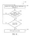
- FIG. 10is a flow diagram of an example process 1000 for determining whether to wear level a memory location.
- the example process 1000can, for example, be implemented in the non-volatile storage 112 , or in a memory driver 110 associated with the non-volatile store 112 , or in some other hardware and/or software memory resource.
- Stage 1002identifies a memory location in response to storing data in a memory device.
- the non-volatile storage 112or a memory driver 110 associated with the non-volatile store 112 can associate a free block pointer with a memory location in response to storing data in a memory device.
- Stage 1004determines whether the identified memory location is associated with a reference memory location. For example, the non-volatile storage 112 , or a memory driver 110 associated with the non-volatile store 112 can determine if the free block pointer FBP is equal to or has incremented past the leveling pointer LP.
- stage 1004determines that the identified memory location is not associated with a reference memory location, the process returns to stage 1002 . If, however, stage 1004 determines that the identified memory location is associated with a reference memory location, then stage 1006 determines whether a wear leveling condition is met. For example, the non-volatile storage 112 , or a memory driver 110 associated with the non-volatile store 112 can determine if one or more of the wear leveling conditions described above has occurred.
- stage 1006determines that a wear leveling condition is not met, then the process returns to stage 1002 . If, however, stage 1006 determines a wear leveling condition is met, then stage 1008 performs a wear leveling process.
- the non-volatile storage 112 , or a memory driver 110 associated with the non-volatile store 112can perform one of the wear leveling processed described above.
- FIG. 11is a flow diagram of an example process 1100 of wear leveling.
- the example process 1000can, for example, be implemented in the non-volatile storage 112 , or in a memory driver 110 associated with the non-volatile store 112 , or in some other hardware and/or software memory resource.
- Stage 1102identifies a first allocated memory location relative to a reference memory location.
- the non-volatile storage 112or a memory driver 110 associated with the non-volatile store 112 can increment a leveling pointer LP from the current address of the leveling pointer LP to identify an allocated memory location.
- Stage 1104identifies an unallocated memory location relative to a first allocated memory location.
- the non-volatile storage 112or a memory driver 110 associated with the non-volatile store 112 can increment a free leveling pointer FLP from the current address of the incremented leveling pointer LP to identify an unallocated memory location.
- Stage 1106allocates the unallocated memory location to store data stored in the first allocated memory location.
- the non-volatile storage 112or a memory driver 110 associated with the non-volatile store 112 can store data in the unallocated memory location pointed to by the free leveling pointer and set the corresponding allocation flag 262 to 1.
- Stage 1108deallocates the first allocated memory location.
- the non-volatile storage 112or a memory driver 110 associated with the non-volatile store 112 can set the corresponding allocation flag of the memory location from which data was moved during the leveling process to 0.
- Stage 1110identifies a memory location relative to the deallocated memory location.
- the non-volatile storage 112or a memory driver 110 associated with the non-volatile store 112 can identify the memory location referenced by the free leveling pointer FLP or a first unallocated memory location incremented from the address of the free leveling pointer FLP.
- Stage 1112designates the identified memory location as the reference memory location.
- the non-volatile storage 112or a memory driver 110 associated with the non-volatile store 112 can set the leveling pointer LP to the address of the memory location identified in stage 1110 .
- FIGS. 2-11 abovedescribe leveling at the block level.
- the mapping table 240 and the pointerscan be updated when the writing operation increments onto the next physical block.
- the processes abovecan be adapted to any memory architecture that includes a sequential addressing scheme.
- the apparatus, methods, flow diagrams, and structure block diagrams described in this patent documentmay be implemented in computer processing systems including program code comprising program instructions that are executable by the computer processing system. Other implementations may also be used. Additionally, the flow diagrams and structure block diagrams described in this patent document, which describe particular methods and/or corresponding acts in support of steps and corresponding functions in support of disclosed structural means, may also be utilized to implement corresponding software structures and algorithms, and equivalents thereof.
Landscapes
- Techniques For Improving Reliability Of Storages (AREA)
- Memory System (AREA)
Abstract
Description
Claims (22)
Priority Applications (5)
| Application Number | Priority Date | Filing Date | Title |
|---|---|---|---|
| US11/743,974US7689762B2 (en) | 2007-05-03 | 2007-05-03 | Storage device wear leveling |
| TW097116411ATWI442228B (en) | 2007-05-03 | 2008-05-02 | Storage device wear leveling |
| DE112008001126.5TDE112008001126B4 (en) | 2007-05-03 | 2008-05-02 | wear compensation |
| PCT/US2008/062520WO2008137755A1 (en) | 2007-05-03 | 2008-05-02 | Wear leveling |
| CN200880014680.5ACN101675479B (en) | 2007-05-03 | 2008-05-02 | Storage Wear Leveling |
Applications Claiming Priority (1)
| Application Number | Priority Date | Filing Date | Title |
|---|---|---|---|
| US11/743,974US7689762B2 (en) | 2007-05-03 | 2007-05-03 | Storage device wear leveling |
Publications (2)
| Publication Number | Publication Date |
|---|---|
| US20080276035A1 US20080276035A1 (en) | 2008-11-06 |
| US7689762B2true US7689762B2 (en) | 2010-03-30 |
Family
ID=39940390
Family Applications (1)
| Application Number | Title | Priority Date | Filing Date |
|---|---|---|---|
| US11/743,974Active2028-02-06US7689762B2 (en) | 2007-05-03 | 2007-05-03 | Storage device wear leveling |
Country Status (5)
| Country | Link |
|---|---|
| US (1) | US7689762B2 (en) |
| CN (1) | CN101675479B (en) |
| DE (1) | DE112008001126B4 (en) |
| TW (1) | TWI442228B (en) |
| WO (1) | WO2008137755A1 (en) |
Cited By (12)
| Publication number | Priority date | Publication date | Assignee | Title |
|---|---|---|---|---|
| US20100185806A1 (en)* | 2009-01-16 | 2010-07-22 | Arvind Pruthi | Caching systems and methods using a solid state disk |
| US20100251009A1 (en)* | 2009-03-27 | 2010-09-30 | Ross John Stenfort | System, method, and computer program product for converting logical block address de-allocation information in a first format to a second format |
| US20100250830A1 (en)* | 2009-03-27 | 2010-09-30 | Ross John Stenfort | System, method, and computer program product for hardening data stored on a solid state disk |
| US20100250829A1 (en)* | 2009-03-27 | 2010-09-30 | Ross John Stenfort | System, method, and computer program product for sending logical block address de-allocation status information |
| US20110004710A1 (en)* | 2009-07-06 | 2011-01-06 | Ross John Stenfort | System, method, and computer program product for interfacing one or more storage devices with a plurality of bridge chips |
| US8539139B1 (en) | 2010-12-17 | 2013-09-17 | Teradota Us, Inc. | Managing device wearout using I/O metering |
| US8671259B2 (en) | 2009-03-27 | 2014-03-11 | Lsi Corporation | Storage system data hardening |
| US9223691B2 (en) | 2012-05-18 | 2015-12-29 | Silicon Motion, Inc. | Data storage device and method for flash block management |
| US20160004615A1 (en)* | 2013-06-03 | 2016-01-07 | Hitachi, Ltd. | Storage apparatus and storage apparatus control method |
| US10157141B2 (en) | 2016-03-09 | 2018-12-18 | Toshiba Memory Corporation | Memory system and method of controlling nonvolatile memory |
| US10802936B2 (en) | 2015-09-14 | 2020-10-13 | Hewlett Packard Enterprise Development Lp | Memory location remapping and wear-levelling |
| WO2020231704A1 (en)* | 2019-05-16 | 2020-11-19 | Micron Technology, Inc. | Codeword rotation for zone grouping of media codewords |
Families Citing this family (10)
| Publication number | Priority date | Publication date | Assignee | Title |
|---|---|---|---|---|
| US8051241B2 (en)* | 2009-05-07 | 2011-11-01 | Seagate Technology Llc | Wear leveling technique for storage devices |
| US20100318719A1 (en)* | 2009-06-12 | 2010-12-16 | Micron Technology, Inc. | Methods, memory controllers and devices for wear leveling a memory |
| US9477590B2 (en)* | 2011-09-16 | 2016-10-25 | Apple Inc. | Weave sequence counter for non-volatile memory systems |
| US20130097403A1 (en)* | 2011-10-18 | 2013-04-18 | Rambus Inc. | Address Mapping in Memory Systems |
| CN102981971B (en)* | 2012-12-25 | 2016-06-08 | 重庆大学 | A kind of phase transition storage loss equalizing method of quick response |
| CN103902463A (en)* | 2012-12-31 | 2014-07-02 | 杨威锋 | High-speed physical address assignment technology of memory device based on flash memories |
| CN103218177A (en)* | 2013-04-19 | 2013-07-24 | 杭州电子科技大学 | NAND Flash storage system with function of data balanced processing |
| KR20170045406A (en)* | 2015-10-16 | 2017-04-27 | 에스케이하이닉스 주식회사 | Data storage device and operating method thereof |
| US20170286311A1 (en)* | 2016-04-01 | 2017-10-05 | Dale J. Juenemann | Repetitive address indirection in a memory |
| US10884889B2 (en) | 2018-06-22 | 2021-01-05 | Seagate Technology Llc | Allocating part of a raid stripe to repair a second raid stripe |
Citations (36)
| Publication number | Priority date | Publication date | Assignee | Title |
|---|---|---|---|---|
| US5404485A (en) | 1993-03-08 | 1995-04-04 | M-Systems Flash Disk Pioneers Ltd. | Flash file system |
| US5537552A (en)* | 1990-11-27 | 1996-07-16 | Canon Kabushiki Kaisha | Apparatus for selectively comparing pointers to detect full or empty status of a circular buffer area in an input/output (I/O) buffer |
| US5930815A (en)* | 1995-07-31 | 1999-07-27 | Lexar Media, Inc. | Moving sequential sectors within a block of information in a flash memory mass storage architecture |
| US5937425A (en) | 1997-10-16 | 1999-08-10 | M-Systems Flash Disk Pioneers Ltd. | Flash file system optimized for page-mode flash technologies |
| US5956473A (en) | 1996-11-25 | 1999-09-21 | Macronix International Co., Ltd. | Method and system for managing a flash memory mass storage system |
| US6000006A (en) | 1997-08-25 | 1999-12-07 | Bit Microsystems, Inc. | Unified re-map and cache-index table with dual write-counters for wear-leveling of non-volatile flash RAM mass storage |
| US6016275A (en) | 1998-03-13 | 2000-01-18 | Lg Semicon Co., Ltd. | Flash memory wear leveling system and method |
| US6092160A (en) | 1996-09-30 | 2000-07-18 | Nokia Mobile Phones Limited | Memory management method |
| US6427186B1 (en) | 1999-03-30 | 2002-07-30 | Frank (Fong-Long) Lin | Memory, interface system and method for mapping logical block numbers to physical sector numbers in a flash memory, using a master index table and a table of physical sector numbers |
| US20030033510A1 (en) | 2001-08-08 | 2003-02-13 | David Dice | Methods and apparatus for controlling speculative execution of instructions based on a multiaccess memory condition |
| US20030065899A1 (en)* | 2001-09-28 | 2003-04-03 | Gorobets Sergey Anatolievich | Memory system sectors |
| US20030163633A1 (en)* | 2002-02-27 | 2003-08-28 | Aasheim Jered Donald | System and method for achieving uniform wear levels in a flash memory device |
| US20030229766A1 (en) | 2002-06-06 | 2003-12-11 | David Dice | Methods and apparatus for performing a memory management technique |
| US20030229753A1 (en) | 2002-06-10 | 2003-12-11 | Samsung Electronics Co., Ltd. | Flash memory file system |
| US6725321B1 (en) | 1999-02-17 | 2004-04-20 | Lexar Media, Inc. | Memory system |
| US20040083335A1 (en) | 2002-10-28 | 2004-04-29 | Gonzalez Carlos J. | Automated wear leveling in non-volatile storage systems |
| US6732221B2 (en) | 2001-06-01 | 2004-05-04 | M-Systems Flash Disk Pioneers Ltd | Wear leveling of static areas in flash memory |
| US20040210706A1 (en) | 2002-07-26 | 2004-10-21 | Samsung Electronics Co., Ltd. | Method for managing flash memory |
| US6850443B2 (en) | 1991-09-13 | 2005-02-01 | Sandisk Corporation | Wear leveling techniques for flash EEPROM systems |
| US20050047229A1 (en) | 2002-12-18 | 2005-03-03 | Benoit Nadeau-Dostie | Method and circuit for collecting memory failure information |
| US20050055495A1 (en)* | 2003-09-05 | 2005-03-10 | Nokia Corporation | Memory wear leveling |
| US6914853B2 (en) | 2001-09-27 | 2005-07-05 | Intel Corporation | Mechanism for efficient wearout counters in destructive readout memory |
| US6973531B1 (en) | 2002-10-28 | 2005-12-06 | Sandisk Corporation | Tracking the most frequently erased blocks in non-volatile memory systems |
| US6985992B1 (en) | 2002-10-28 | 2006-01-10 | Sandisk Corporation | Wear-leveling in non-volatile storage systems |
| US7035967B2 (en) | 2002-10-28 | 2006-04-25 | Sandisk Corporation | Maintaining an average erase count in a non-volatile storage system |
| US20060106972A1 (en)* | 2004-11-15 | 2006-05-18 | Gorobets Sergey A | Cyclic flash memory wear leveling |
| US20060161724A1 (en)* | 2005-01-20 | 2006-07-20 | Bennett Alan D | Scheduling of housekeeping operations in flash memory systems |
| US7096313B1 (en) | 2002-10-28 | 2006-08-22 | Sandisk Corporation | Tracking the least frequently erased blocks in non-volatile memory systems |
| US20060256623A1 (en) | 2005-05-12 | 2006-11-16 | Micron Technology, Inc. | Partial string erase scheme in a flash memory device |
| US7139863B1 (en) | 2003-09-26 | 2006-11-21 | Storage Technology Corporation | Method and system for improving usable life of memory devices using vector processing |
| US20060288153A1 (en) | 2005-06-21 | 2006-12-21 | Katsuya Tanaka | Storage system using flash memory |
| US20070050536A1 (en)* | 2005-09-01 | 2007-03-01 | Cypress Semiconductor Corporation | Flash drive fast wear leveling |
| US20070103992A1 (en)* | 2005-11-10 | 2007-05-10 | Sony Corporation | Memory system |
| US20070150644A1 (en)* | 2005-12-28 | 2007-06-28 | Yosi Pinto | System for writing non-volatile memories for increased endurance |
| US20070208904A1 (en)* | 2006-03-03 | 2007-09-06 | Wu-Han Hsieh | Wear leveling method and apparatus for nonvolatile memory |
| US7315917B2 (en)* | 2005-01-20 | 2008-01-01 | Sandisk Corporation | Scheduling of housekeeping operations in flash memory systems |
- 2007
- 2007-05-03USUS11/743,974patent/US7689762B2/enactiveActive
- 2008
- 2008-05-02DEDE112008001126.5Tpatent/DE112008001126B4/ennot_activeExpired - Fee Related
- 2008-05-02WOPCT/US2008/062520patent/WO2008137755A1/enactiveApplication Filing
- 2008-05-02CNCN200880014680.5Apatent/CN101675479B/ennot_activeExpired - Fee Related
- 2008-05-02TWTW097116411Apatent/TWI442228B/ennot_activeIP Right Cessation
Patent Citations (38)
| Publication number | Priority date | Publication date | Assignee | Title |
|---|---|---|---|---|
| US5537552A (en)* | 1990-11-27 | 1996-07-16 | Canon Kabushiki Kaisha | Apparatus for selectively comparing pointers to detect full or empty status of a circular buffer area in an input/output (I/O) buffer |
| US6850443B2 (en) | 1991-09-13 | 2005-02-01 | Sandisk Corporation | Wear leveling techniques for flash EEPROM systems |
| US5404485A (en) | 1993-03-08 | 1995-04-04 | M-Systems Flash Disk Pioneers Ltd. | Flash file system |
| US5930815A (en)* | 1995-07-31 | 1999-07-27 | Lexar Media, Inc. | Moving sequential sectors within a block of information in a flash memory mass storage architecture |
| US6092160A (en) | 1996-09-30 | 2000-07-18 | Nokia Mobile Phones Limited | Memory management method |
| US5956473A (en) | 1996-11-25 | 1999-09-21 | Macronix International Co., Ltd. | Method and system for managing a flash memory mass storage system |
| US6000006A (en) | 1997-08-25 | 1999-12-07 | Bit Microsystems, Inc. | Unified re-map and cache-index table with dual write-counters for wear-leveling of non-volatile flash RAM mass storage |
| US5937425A (en) | 1997-10-16 | 1999-08-10 | M-Systems Flash Disk Pioneers Ltd. | Flash file system optimized for page-mode flash technologies |
| US6016275A (en) | 1998-03-13 | 2000-01-18 | Lg Semicon Co., Ltd. | Flash memory wear leveling system and method |
| US6725321B1 (en) | 1999-02-17 | 2004-04-20 | Lexar Media, Inc. | Memory system |
| US6427186B1 (en) | 1999-03-30 | 2002-07-30 | Frank (Fong-Long) Lin | Memory, interface system and method for mapping logical block numbers to physical sector numbers in a flash memory, using a master index table and a table of physical sector numbers |
| US6732221B2 (en) | 2001-06-01 | 2004-05-04 | M-Systems Flash Disk Pioneers Ltd | Wear leveling of static areas in flash memory |
| US20030033510A1 (en) | 2001-08-08 | 2003-02-13 | David Dice | Methods and apparatus for controlling speculative execution of instructions based on a multiaccess memory condition |
| US6914853B2 (en) | 2001-09-27 | 2005-07-05 | Intel Corporation | Mechanism for efficient wearout counters in destructive readout memory |
| US20030065899A1 (en)* | 2001-09-28 | 2003-04-03 | Gorobets Sergey Anatolievich | Memory system sectors |
| US20030163633A1 (en)* | 2002-02-27 | 2003-08-28 | Aasheim Jered Donald | System and method for achieving uniform wear levels in a flash memory device |
| US20030229766A1 (en) | 2002-06-06 | 2003-12-11 | David Dice | Methods and apparatus for performing a memory management technique |
| US20030229753A1 (en) | 2002-06-10 | 2003-12-11 | Samsung Electronics Co., Ltd. | Flash memory file system |
| US20040210706A1 (en) | 2002-07-26 | 2004-10-21 | Samsung Electronics Co., Ltd. | Method for managing flash memory |
| US20040083335A1 (en) | 2002-10-28 | 2004-04-29 | Gonzalez Carlos J. | Automated wear leveling in non-volatile storage systems |
| US6973531B1 (en) | 2002-10-28 | 2005-12-06 | Sandisk Corporation | Tracking the most frequently erased blocks in non-volatile memory systems |
| US6985992B1 (en) | 2002-10-28 | 2006-01-10 | Sandisk Corporation | Wear-leveling in non-volatile storage systems |
| US7035967B2 (en) | 2002-10-28 | 2006-04-25 | Sandisk Corporation | Maintaining an average erase count in a non-volatile storage system |
| US20070083698A1 (en)* | 2002-10-28 | 2007-04-12 | Gonzalez Carlos J | Automated Wear Leveling in Non-Volatile Storage Systems |
| US7096313B1 (en) | 2002-10-28 | 2006-08-22 | Sandisk Corporation | Tracking the least frequently erased blocks in non-volatile memory systems |
| US7120729B2 (en) | 2002-10-28 | 2006-10-10 | Sandisk Corporation | Automated wear leveling in non-volatile storage systems |
| US20050047229A1 (en) | 2002-12-18 | 2005-03-03 | Benoit Nadeau-Dostie | Method and circuit for collecting memory failure information |
| US20050055495A1 (en)* | 2003-09-05 | 2005-03-10 | Nokia Corporation | Memory wear leveling |
| US7139863B1 (en) | 2003-09-26 | 2006-11-21 | Storage Technology Corporation | Method and system for improving usable life of memory devices using vector processing |
| US20060106972A1 (en)* | 2004-11-15 | 2006-05-18 | Gorobets Sergey A | Cyclic flash memory wear leveling |
| US20060161724A1 (en)* | 2005-01-20 | 2006-07-20 | Bennett Alan D | Scheduling of housekeeping operations in flash memory systems |
| US7315917B2 (en)* | 2005-01-20 | 2008-01-01 | Sandisk Corporation | Scheduling of housekeeping operations in flash memory systems |
| US20060256623A1 (en) | 2005-05-12 | 2006-11-16 | Micron Technology, Inc. | Partial string erase scheme in a flash memory device |
| US20060288153A1 (en) | 2005-06-21 | 2006-12-21 | Katsuya Tanaka | Storage system using flash memory |
| US20070050536A1 (en)* | 2005-09-01 | 2007-03-01 | Cypress Semiconductor Corporation | Flash drive fast wear leveling |
| US20070103992A1 (en)* | 2005-11-10 | 2007-05-10 | Sony Corporation | Memory system |
| US20070150644A1 (en)* | 2005-12-28 | 2007-06-28 | Yosi Pinto | System for writing non-volatile memories for increased endurance |
| US20070208904A1 (en)* | 2006-03-03 | 2007-09-06 | Wu-Han Hsieh | Wear leveling method and apparatus for nonvolatile memory |
Cited By (18)
| Publication number | Priority date | Publication date | Assignee | Title |
|---|---|---|---|---|
| US20100185806A1 (en)* | 2009-01-16 | 2010-07-22 | Arvind Pruthi | Caching systems and methods using a solid state disk |
| US8671259B2 (en) | 2009-03-27 | 2014-03-11 | Lsi Corporation | Storage system data hardening |
| US20100251009A1 (en)* | 2009-03-27 | 2010-09-30 | Ross John Stenfort | System, method, and computer program product for converting logical block address de-allocation information in a first format to a second format |
| US20100250830A1 (en)* | 2009-03-27 | 2010-09-30 | Ross John Stenfort | System, method, and computer program product for hardening data stored on a solid state disk |
| US20100250829A1 (en)* | 2009-03-27 | 2010-09-30 | Ross John Stenfort | System, method, and computer program product for sending logical block address de-allocation status information |
| US8090905B2 (en) | 2009-03-27 | 2012-01-03 | Sandforce, Inc. | System, method, and computer program product for converting logical block address de-allocation information in a first format to a second format |
| US8230159B2 (en)* | 2009-03-27 | 2012-07-24 | Lsi Corporation | System, method, and computer program product for sending logical block address de-allocation status information |
| US20110004710A1 (en)* | 2009-07-06 | 2011-01-06 | Ross John Stenfort | System, method, and computer program product for interfacing one or more storage devices with a plurality of bridge chips |
| US9792074B2 (en) | 2009-07-06 | 2017-10-17 | Seagate Technology Llc | System, method, and computer program product for interfacing one or more storage devices with a plurality of bridge chips |
| US8539139B1 (en) | 2010-12-17 | 2013-09-17 | Teradota Us, Inc. | Managing device wearout using I/O metering |
| US9223691B2 (en) | 2012-05-18 | 2015-12-29 | Silicon Motion, Inc. | Data storage device and method for flash block management |
| US20160004615A1 (en)* | 2013-06-03 | 2016-01-07 | Hitachi, Ltd. | Storage apparatus and storage apparatus control method |
| US10013322B2 (en)* | 2013-06-03 | 2018-07-03 | Hitachi, Ltd. | Storage apparatus and storage apparatus control method |
| US10802936B2 (en) | 2015-09-14 | 2020-10-13 | Hewlett Packard Enterprise Development Lp | Memory location remapping and wear-levelling |
| US10157141B2 (en) | 2016-03-09 | 2018-12-18 | Toshiba Memory Corporation | Memory system and method of controlling nonvolatile memory |
| WO2020231704A1 (en)* | 2019-05-16 | 2020-11-19 | Micron Technology, Inc. | Codeword rotation for zone grouping of media codewords |
| US11119946B2 (en) | 2019-05-16 | 2021-09-14 | Micron Technology, Inc. | Codeword rotation for zone grouping of media codewords |
| US11720502B2 (en) | 2019-05-16 | 2023-08-08 | Micron Technology, Inc. | Codeword rotation for zone grouping of media codewords |
Also Published As
| Publication number | Publication date |
|---|---|
| TW200900927A (en) | 2009-01-01 |
| WO2008137755A1 (en) | 2008-11-13 |
| CN101675479B (en) | 2013-06-12 |
| TWI442228B (en) | 2014-06-21 |
| DE112008001126T5 (en) | 2010-03-25 |
| US20080276035A1 (en) | 2008-11-06 |
| CN101675479A (en) | 2010-03-17 |
| DE112008001126B4 (en) | 2018-07-12 |
Similar Documents
| Publication | Publication Date | Title |
|---|---|---|
| US7689762B2 (en) | Storage device wear leveling | |
| US7797479B2 (en) | Technique to write to a non-volatile memory | |
| US7594067B2 (en) | Enhanced data access in a storage device | |
| KR101788332B1 (en) | Mount-time unmapping of unused logical addresses in non-volatile memory systems | |
| US8713381B2 (en) | Systems and methods of using dynamic data for wear leveling in solid-state devices | |
| US20080189490A1 (en) | Memory mapping | |
| US8244959B2 (en) | Software adapted wear leveling | |
| US8769189B2 (en) | Method and apparatus for byte-access in block-based flash memory | |
| US10073771B2 (en) | Data storage method and system thereof | |
| US7287117B2 (en) | Flash memory and mapping control apparatus and method for flash memory | |
| US20080235306A1 (en) | Garbage collection in nonvolatile memories using data attributes, computer program products and methods of operating the same | |
| US20100095046A1 (en) | Method and apparatus for improving small write performance in a non-volatile memory | |
| GB2291990A (en) | Flash-memory management system | |
| JP6908789B2 (en) | Multi-level addressing | |
| JP5858081B2 (en) | Memory controller, memory system, and memory control method | |
| US20090254729A1 (en) | Method of wear leveling for a non-volatile memory | |
| CN101901190B (en) | Electronic device, apparatus and method for managing memory in the electronic device | |
| CN111367823B (en) | Method and device for writing effective data | |
| US20150220432A1 (en) | Method and apparatus for managing at least one non-volatile memory | |
| CN110806987A (en) | Hybrid mapping table on static random access memory | |
| US20110055459A1 (en) | Method for managing a plurality of blocks of a flash memory, and associated memory device and controller thereof |
Legal Events
| Date | Code | Title | Description |
|---|---|---|---|
| AS | Assignment | Owner name:ATMEL CORPORATION, CALIFORNIA Free format text:ASSIGNMENT OF ASSIGNORS INTEREST;ASSIGNOR:HOBSON, RUSSELL;REEL/FRAME:019381/0683 Effective date:20070503 Owner name:ATMEL CORPORATION,CALIFORNIA Free format text:ASSIGNMENT OF ASSIGNORS INTEREST;ASSIGNOR:HOBSON, RUSSELL;REEL/FRAME:019381/0683 Effective date:20070503 | |
| STCF | Information on status: patent grant | Free format text:PATENTED CASE | |
| CC | Certificate of correction | ||
| FPAY | Fee payment | Year of fee payment:4 | |
| AS | Assignment | Owner name:MORGAN STANLEY SENIOR FUNDING, INC. AS ADMINISTRATIVE AGENT, NEW YORK Free format text:PATENT SECURITY AGREEMENT;ASSIGNOR:ATMEL CORPORATION;REEL/FRAME:031912/0173 Effective date:20131206 Owner name:MORGAN STANLEY SENIOR FUNDING, INC. AS ADMINISTRAT Free format text:PATENT SECURITY AGREEMENT;ASSIGNOR:ATMEL CORPORATION;REEL/FRAME:031912/0173 Effective date:20131206 | |
| AS | Assignment | Owner name:ATMEL CORPORATION, CALIFORNIA Free format text:TERMINATION AND RELEASE OF SECURITY INTEREST IN PATENT COLLATERAL;ASSIGNOR:MORGAN STANLEY SENIOR FUNDING, INC.;REEL/FRAME:038376/0001 Effective date:20160404 | |
| AS | Assignment | Owner name:JPMORGAN CHASE BANK, N.A., AS ADMINISTRATIVE AGENT, ILLINOIS Free format text:SECURITY INTEREST;ASSIGNOR:ATMEL CORPORATION;REEL/FRAME:041715/0747 Effective date:20170208 Owner name:JPMORGAN CHASE BANK, N.A., AS ADMINISTRATIVE AGENT Free format text:SECURITY INTEREST;ASSIGNOR:ATMEL CORPORATION;REEL/FRAME:041715/0747 Effective date:20170208 | |
| MAFP | Maintenance fee payment | Free format text:PAYMENT OF MAINTENANCE FEE, 8TH YEAR, LARGE ENTITY (ORIGINAL EVENT CODE: M1552) Year of fee payment:8 | |
| AS | Assignment | Owner name:JPMORGAN CHASE BANK, N.A., AS ADMINISTRATIVE AGENT, ILLINOIS Free format text:SECURITY INTEREST;ASSIGNORS:MICROCHIP TECHNOLOGY INCORPORATED;SILICON STORAGE TECHNOLOGY, INC.;ATMEL CORPORATION;AND OTHERS;REEL/FRAME:046426/0001 Effective date:20180529 Owner name:JPMORGAN CHASE BANK, N.A., AS ADMINISTRATIVE AGENT Free format text:SECURITY INTEREST;ASSIGNORS:MICROCHIP TECHNOLOGY INCORPORATED;SILICON STORAGE TECHNOLOGY, INC.;ATMEL CORPORATION;AND OTHERS;REEL/FRAME:046426/0001 Effective date:20180529 | |
| AS | Assignment | Owner name:WELLS FARGO BANK, NATIONAL ASSOCIATION, AS NOTES COLLATERAL AGENT, CALIFORNIA Free format text:SECURITY INTEREST;ASSIGNORS:MICROCHIP TECHNOLOGY INCORPORATED;SILICON STORAGE TECHNOLOGY, INC.;ATMEL CORPORATION;AND OTHERS;REEL/FRAME:047103/0206 Effective date:20180914 Owner name:WELLS FARGO BANK, NATIONAL ASSOCIATION, AS NOTES C Free format text:SECURITY INTEREST;ASSIGNORS:MICROCHIP TECHNOLOGY INCORPORATED;SILICON STORAGE TECHNOLOGY, INC.;ATMEL CORPORATION;AND OTHERS;REEL/FRAME:047103/0206 Effective date:20180914 | |
| AS | Assignment | Owner name:JPMORGAN CHASE BANK, N.A., AS ADMINISTRATIVE AGENT, DELAWARE Free format text:SECURITY INTEREST;ASSIGNORS:MICROCHIP TECHNOLOGY INC.;SILICON STORAGE TECHNOLOGY, INC.;ATMEL CORPORATION;AND OTHERS;REEL/FRAME:053311/0305 Effective date:20200327 | |
| AS | Assignment | Owner name:ATMEL CORPORATION, ARIZONA Free format text:RELEASE BY SECURED PARTY;ASSIGNOR:JPMORGAN CHASE BANK, N.A, AS ADMINISTRATIVE AGENT;REEL/FRAME:053466/0011 Effective date:20200529 Owner name:SILICON STORAGE TECHNOLOGY, INC., ARIZONA Free format text:RELEASE BY SECURED PARTY;ASSIGNOR:JPMORGAN CHASE BANK, N.A, AS ADMINISTRATIVE AGENT;REEL/FRAME:053466/0011 Effective date:20200529 Owner name:MICROCHIP TECHNOLOGY INC., ARIZONA Free format text:RELEASE BY SECURED PARTY;ASSIGNOR:JPMORGAN CHASE BANK, N.A, AS ADMINISTRATIVE AGENT;REEL/FRAME:053466/0011 Effective date:20200529 Owner name:MICROSEMI CORPORATION, CALIFORNIA Free format text:RELEASE BY SECURED PARTY;ASSIGNOR:JPMORGAN CHASE BANK, N.A, AS ADMINISTRATIVE AGENT;REEL/FRAME:053466/0011 Effective date:20200529 Owner name:MICROSEMI STORAGE SOLUTIONS, INC., ARIZONA Free format text:RELEASE BY SECURED PARTY;ASSIGNOR:JPMORGAN CHASE BANK, N.A, AS ADMINISTRATIVE AGENT;REEL/FRAME:053466/0011 Effective date:20200529 | |
| AS | Assignment | Owner name:WELLS FARGO BANK, NATIONAL ASSOCIATION, MINNESOTA Free format text:SECURITY INTEREST;ASSIGNORS:MICROCHIP TECHNOLOGY INC.;SILICON STORAGE TECHNOLOGY, INC.;ATMEL CORPORATION;AND OTHERS;REEL/FRAME:053468/0705 Effective date:20200529 | |
| AS | Assignment | Owner name:WELLS FARGO BANK, NATIONAL ASSOCIATION, AS COLLATERAL AGENT, MINNESOTA Free format text:SECURITY INTEREST;ASSIGNORS:MICROCHIP TECHNOLOGY INCORPORATED;SILICON STORAGE TECHNOLOGY, INC.;ATMEL CORPORATION;AND OTHERS;REEL/FRAME:055671/0612 Effective date:20201217 | |
| AS | Assignment | Owner name:WELLS FARGO BANK, NATIONAL ASSOCIATION, AS NOTES COLLATERAL AGENT, MINNESOTA Free format text:SECURITY INTEREST;ASSIGNORS:MICROCHIP TECHNOLOGY INCORPORATED;SILICON STORAGE TECHNOLOGY, INC.;ATMEL CORPORATION;AND OTHERS;REEL/FRAME:057935/0474 Effective date:20210528 | |
| MAFP | Maintenance fee payment | Free format text:PAYMENT OF MAINTENANCE FEE, 12TH YEAR, LARGE ENTITY (ORIGINAL EVENT CODE: M1553); ENTITY STATUS OF PATENT OWNER: LARGE ENTITY Year of fee payment:12 | |
| AS | Assignment | Owner name:MICROSEMI STORAGE SOLUTIONS, INC., ARIZONA Free format text:RELEASE BY SECURED PARTY;ASSIGNOR:JPMORGAN CHASE BANK, N.A., AS ADMINISTRATIVE AGENT;REEL/FRAME:059333/0222 Effective date:20220218 Owner name:MICROSEMI CORPORATION, ARIZONA Free format text:RELEASE BY SECURED PARTY;ASSIGNOR:JPMORGAN CHASE BANK, N.A., AS ADMINISTRATIVE AGENT;REEL/FRAME:059333/0222 Effective date:20220218 Owner name:ATMEL CORPORATION, ARIZONA Free format text:RELEASE BY SECURED PARTY;ASSIGNOR:JPMORGAN CHASE BANK, N.A., AS ADMINISTRATIVE AGENT;REEL/FRAME:059333/0222 Effective date:20220218 Owner name:SILICON STORAGE TECHNOLOGY, INC., ARIZONA Free format text:RELEASE BY SECURED PARTY;ASSIGNOR:JPMORGAN CHASE BANK, N.A., AS ADMINISTRATIVE AGENT;REEL/FRAME:059333/0222 Effective date:20220218 Owner name:MICROCHIP TECHNOLOGY INCORPORATED, ARIZONA Free format text:RELEASE BY SECURED PARTY;ASSIGNOR:JPMORGAN CHASE BANK, N.A., AS ADMINISTRATIVE AGENT;REEL/FRAME:059333/0222 Effective date:20220218 | |
| AS | Assignment | Owner name:ATMEL CORPORATION, ARIZONA Free format text:RELEASE BY SECURED PARTY;ASSIGNOR:JPMORGAN CHASE BANK, N.A., AS ADMINISTRATIVE AGENT;REEL/FRAME:059262/0105 Effective date:20220218 | |
| AS | Assignment | Owner name:MICROSEMI STORAGE SOLUTIONS, INC., ARIZONA Free format text:RELEASE BY SECURED PARTY;ASSIGNOR:WELLS FARGO BANK, NATIONAL ASSOCIATION, AS NOTES COLLATERAL AGENT;REEL/FRAME:059358/0001 Effective date:20220228 Owner name:MICROSEMI CORPORATION, ARIZONA Free format text:RELEASE BY SECURED PARTY;ASSIGNOR:WELLS FARGO BANK, NATIONAL ASSOCIATION, AS NOTES COLLATERAL AGENT;REEL/FRAME:059358/0001 Effective date:20220228 Owner name:ATMEL CORPORATION, ARIZONA Free format text:RELEASE BY SECURED PARTY;ASSIGNOR:WELLS FARGO BANK, NATIONAL ASSOCIATION, AS NOTES COLLATERAL AGENT;REEL/FRAME:059358/0001 Effective date:20220228 Owner name:SILICON STORAGE TECHNOLOGY, INC., ARIZONA Free format text:RELEASE BY SECURED PARTY;ASSIGNOR:WELLS FARGO BANK, NATIONAL ASSOCIATION, AS NOTES COLLATERAL AGENT;REEL/FRAME:059358/0001 Effective date:20220228 Owner name:MICROCHIP TECHNOLOGY INCORPORATED, ARIZONA Free format text:RELEASE BY SECURED PARTY;ASSIGNOR:WELLS FARGO BANK, NATIONAL ASSOCIATION, AS NOTES COLLATERAL AGENT;REEL/FRAME:059358/0001 Effective date:20220228 | |
| AS | Assignment | Owner name:MICROSEMI STORAGE SOLUTIONS, INC., ARIZONA Free format text:RELEASE BY SECURED PARTY;ASSIGNOR:WELLS FARGO BANK, NATIONAL ASSOCIATION, AS NOTES COLLATERAL AGENT;REEL/FRAME:059863/0400 Effective date:20220228 Owner name:MICROSEMI CORPORATION, ARIZONA Free format text:RELEASE BY SECURED PARTY;ASSIGNOR:WELLS FARGO BANK, NATIONAL ASSOCIATION, AS NOTES COLLATERAL AGENT;REEL/FRAME:059863/0400 Effective date:20220228 Owner name:ATMEL CORPORATION, ARIZONA Free format text:RELEASE BY SECURED PARTY;ASSIGNOR:WELLS FARGO BANK, NATIONAL ASSOCIATION, AS NOTES COLLATERAL AGENT;REEL/FRAME:059863/0400 Effective date:20220228 Owner name:SILICON STORAGE TECHNOLOGY, INC., ARIZONA Free format text:RELEASE BY SECURED PARTY;ASSIGNOR:WELLS FARGO BANK, NATIONAL ASSOCIATION, AS NOTES COLLATERAL AGENT;REEL/FRAME:059863/0400 Effective date:20220228 Owner name:MICROCHIP TECHNOLOGY INCORPORATED, ARIZONA Free format text:RELEASE BY SECURED PARTY;ASSIGNOR:WELLS FARGO BANK, NATIONAL ASSOCIATION, AS NOTES COLLATERAL AGENT;REEL/FRAME:059863/0400 Effective date:20220228 | |
| AS | Assignment | Owner name:MICROSEMI STORAGE SOLUTIONS, INC., ARIZONA Free format text:RELEASE BY SECURED PARTY;ASSIGNOR:WELLS FARGO BANK, NATIONAL ASSOCIATION, AS NOTES COLLATERAL AGENT;REEL/FRAME:059363/0001 Effective date:20220228 Owner name:MICROSEMI CORPORATION, ARIZONA Free format text:RELEASE BY SECURED PARTY;ASSIGNOR:WELLS FARGO BANK, NATIONAL ASSOCIATION, AS NOTES COLLATERAL AGENT;REEL/FRAME:059363/0001 Effective date:20220228 Owner name:ATMEL CORPORATION, ARIZONA Free format text:RELEASE BY SECURED PARTY;ASSIGNOR:WELLS FARGO BANK, NATIONAL ASSOCIATION, AS NOTES COLLATERAL AGENT;REEL/FRAME:059363/0001 Effective date:20220228 Owner name:SILICON STORAGE TECHNOLOGY, INC., ARIZONA Free format text:RELEASE BY SECURED PARTY;ASSIGNOR:WELLS FARGO BANK, NATIONAL ASSOCIATION, AS NOTES COLLATERAL AGENT;REEL/FRAME:059363/0001 Effective date:20220228 Owner name:MICROCHIP TECHNOLOGY INCORPORATED, ARIZONA Free format text:RELEASE BY SECURED PARTY;ASSIGNOR:WELLS FARGO BANK, NATIONAL ASSOCIATION, AS NOTES COLLATERAL AGENT;REEL/FRAME:059363/0001 Effective date:20220228 | |
| AS | Assignment | Owner name:MICROSEMI STORAGE SOLUTIONS, INC., ARIZONA Free format text:RELEASE BY SECURED PARTY;ASSIGNOR:WELLS FARGO BANK, NATIONAL ASSOCIATION, AS NOTES COLLATERAL AGENT;REEL/FRAME:060894/0437 Effective date:20220228 Owner name:MICROSEMI CORPORATION, ARIZONA Free format text:RELEASE BY SECURED PARTY;ASSIGNOR:WELLS FARGO BANK, NATIONAL ASSOCIATION, AS NOTES COLLATERAL AGENT;REEL/FRAME:060894/0437 Effective date:20220228 Owner name:ATMEL CORPORATION, ARIZONA Free format text:RELEASE BY SECURED PARTY;ASSIGNOR:WELLS FARGO BANK, NATIONAL ASSOCIATION, AS NOTES COLLATERAL AGENT;REEL/FRAME:060894/0437 Effective date:20220228 Owner name:SILICON STORAGE TECHNOLOGY, INC., ARIZONA Free format text:RELEASE BY SECURED PARTY;ASSIGNOR:WELLS FARGO BANK, NATIONAL ASSOCIATION, AS NOTES COLLATERAL AGENT;REEL/FRAME:060894/0437 Effective date:20220228 Owner name:MICROCHIP TECHNOLOGY INCORPORATED, ARIZONA Free format text:RELEASE BY SECURED PARTY;ASSIGNOR:WELLS FARGO BANK, NATIONAL ASSOCIATION, AS NOTES COLLATERAL AGENT;REEL/FRAME:060894/0437 Effective date:20220228 |