US7689197B2 - Portable audio system with docking cradle - Google Patents
Portable audio system with docking cradleDownload PDFInfo
- Publication number
- US7689197B2 US7689197B2US11/615,674US61567406AUS7689197B2US 7689197 B2US7689197 B2US 7689197B2US 61567406 AUS61567406 AUS 61567406AUS 7689197 B2US7689197 B2US 7689197B2
- Authority
- US
- United States
- Prior art keywords
- audio system
- portable audio
- docking cradle
- housing
- waveguide
- Prior art date
- Legal status (The legal status is an assumption and is not a legal conclusion. Google has not performed a legal analysis and makes no representation as to the accuracy of the status listed.)
- Expired - Fee Related, expires
Links
Images


Classifications
- G—PHYSICS
- G11—INFORMATION STORAGE
- G11B—INFORMATION STORAGE BASED ON RELATIVE MOVEMENT BETWEEN RECORD CARRIER AND TRANSDUCER
- G11B33/00—Constructional parts, details or accessories not provided for in the other groups of this subclass
- G11B33/12—Disposition of constructional parts in the apparatus, e.g. of power supply, of modules
- G11B33/121—Disposition of constructional parts in the apparatus, e.g. of power supply, of modules the apparatus comprising a single recording/reproducing device
- G11B33/122—Arrangements for providing electrical connections, e.g. connectors, cables, switches
- G—PHYSICS
- G11—INFORMATION STORAGE
- G11B—INFORMATION STORAGE BASED ON RELATIVE MOVEMENT BETWEEN RECORD CARRIER AND TRANSDUCER
- G11B17/00—Guiding record carriers not specifically of filamentary or web form, or of supports therefor
- G11B17/02—Details
- G11B17/04—Feeding or guiding single record carrier to or from transducer unit
- G11B17/0401—Details
- G11B17/0405—Closing mechanism, e.g. door
- G—PHYSICS
- G11—INFORMATION STORAGE
- G11B—INFORMATION STORAGE BASED ON RELATIVE MOVEMENT BETWEEN RECORD CARRIER AND TRANSDUCER
- G11B33/00—Constructional parts, details or accessories not provided for in the other groups of this subclass
- G11B33/02—Cabinets; Cases; Stands; Disposition of apparatus therein or thereon
- G11B33/027—Covers
- H—ELECTRICITY
- H04—ELECTRIC COMMUNICATION TECHNIQUE
- H04R—LOUDSPEAKERS, MICROPHONES, GRAMOPHONE PICK-UPS OR LIKE ACOUSTIC ELECTROMECHANICAL TRANSDUCERS; DEAF-AID SETS; PUBLIC ADDRESS SYSTEMS
- H04R1/00—Details of transducers, loudspeakers or microphones
- H04R1/02—Casings; Cabinets ; Supports therefor; Mountings therein
- H04R1/028—Casings; Cabinets ; Supports therefor; Mountings therein associated with devices performing functions other than acoustics, e.g. electric candles
- H—ELECTRICITY
- H04—ELECTRIC COMMUNICATION TECHNIQUE
- H04R—LOUDSPEAKERS, MICROPHONES, GRAMOPHONE PICK-UPS OR LIKE ACOUSTIC ELECTROMECHANICAL TRANSDUCERS; DEAF-AID SETS; PUBLIC ADDRESS SYSTEMS
- H04R1/00—Details of transducers, loudspeakers or microphones
- H04R1/20—Arrangements for obtaining desired frequency or directional characteristics
- H04R1/22—Arrangements for obtaining desired frequency or directional characteristics for obtaining desired frequency characteristic only
- H04R1/28—Transducer mountings or enclosures modified by provision of mechanical or acoustic impedances, e.g. resonator, damping means
- H04R1/2807—Enclosures comprising vibrating or resonating arrangements
- H04R1/2853—Enclosures comprising vibrating or resonating arrangements using an acoustic labyrinth or a transmission line
- H04R1/2857—Enclosures comprising vibrating or resonating arrangements using an acoustic labyrinth or a transmission line for loudspeaker transducers
- H—ELECTRICITY
- H04—ELECTRIC COMMUNICATION TECHNIQUE
- H04R—LOUDSPEAKERS, MICROPHONES, GRAMOPHONE PICK-UPS OR LIKE ACOUSTIC ELECTROMECHANICAL TRANSDUCERS; DEAF-AID SETS; PUBLIC ADDRESS SYSTEMS
- H04R2205/00—Details of stereophonic arrangements covered by H04R5/00 but not provided for in any of its subgroups
- H04R2205/021—Aspects relating to docking-station type assemblies to obtain an acoustical effect, e.g. the type of connection to external loudspeakers or housings, frequency improvement
Definitions
- the inventionis embodied in a portable audio system.
- the portable audio systemincludes a housing.
- a docking cradleincludes a connector that is electrically coupled to the electronic audio circuit.
- the docking cradleis mechanically coupled to the housing such that the docking cradle is capable of being rotated horizontally between an open position in which the connector is external to the housing and a closed position.
- the connectoris concealed by the housing in the closed position.
- the portable audio systemcan also include a mounting assembly that couples the docking cradle to the housing.
- the mounting assemblyincludes a rack coupled to the housing that engages a pinion coupled to the docking cradle.
- the pinionincludes a gear that is coupled to a viscous damper.
- the gearcan be viscously damped.
- the mounting assemblyincludes a spring that urges the docking cradle to the open position.
- the mounting assemblycan include a stop that prevents the docking cradle from over-rotating in the open position.
- the mounting assemblycan include a latch that prevents the docking cradle from inadvertently opening when the docking cradle is in the closed position.
- the mounting assemblyis concealed by the housing.
- the portable audio systemcan also include a conduit that is positioned between the housing and the docking cradle.
- the conduitsupports at least one cable extending from the housing to the docking cradle.
- a surface of the docking cradleis substantially flush with a front surface of the housing when the docking cradle is in the closed position.
- the connector of the docking cradlecan interfere with at least one of an MP3 player, a CD player, a DVD player, a satellite radio, a terrestrial radio, a tape player, a PDA, a computer, a cellular telephone, and a digital camera.
- the docking cradlerotates along an axis that is substantially parallel to a front surface of the housing.
- the docking cradlecan rotate by substantially 170 degrees.
- the docking cradlecan accept a plurality of docking cradle inserts that accommodate a plurality of external audio sources.
- the docking cradlecan be angled relative to a horizontal plane.
- a front surface of the housingcan be angled relative to a vertical plane.
- the portable audio systemcan also include an acoustic exit that exists the housing.
- the acoustic exitincludes a shape that facilitates the grasping of the housing with a plurality of fingers from a single human hand.
- the acoustic exitis the exit to a waveguide.
- the acoustic exitis the exit of a port.
- the portable audio systemcomprises an electronic audio circuit coupled to the housing.
- the portable audio systemcomprises a housing, and means for coupling a docking cradle to the housing such that the docking cradle is capable of being rotated horizontally between an open position and a closed position in which a substantial portion of the docking cradle is concealed by the housing.
- FIG. 1Ais a front perspective view of a portable audio system according to one embodiment of the invention.
- FIG. 1Billustrates another front perspective view of the portable audio system of FIG. 1A .
- FIG. 1Cillustrates a bottom perspective view of the portable audio system of FIG. 1A .
- FIG. 2Aillustrates a front perspective view of a portable energy source for powering a portable audio system.
- FIG. 2Billustrates a back perspective view of the portable energy sources of FIG. 2A .
- FIG. 3illustrates a partially exploded view of a docking cradle of the portable audio system.
- FIG. 4illustrates a bottom view of a section of the housing that accommodates the docking cradle.
- FIGS. 5A-5Cillustrate, respectively, a top view, a front view and a side view of the portable audio system.
- FIG. 6Aillustrates a rear perspective view of the portable audio system.
- FIG. 6Billustrates another rear perspective view of the portable audio system.
- FIG. 7Ais a perspective view of a waveguide according to one embodiment of the invention.
- FIG. 7Bis an exploded view of the waveguide of FIG. 7A .
- FIG. 8is a perspective view of the interior of the portable audio system illustrating a waveguide.
- Exemplary acoustic waveguidescan be found in U.S. Pat. Nos. 4,628,528 and 6,278,789 and patent application Ser. No. 10/699,304, filed Oct. 31, 2003.
- FIG. 1Ais a front perspective view of a portable audio system 100 .
- the portable audio system 100includes a housing 102 and a docking cradle 104 .
- a portable music playersuch as a MP3 player 106 is shown connected to the docking cradle 104 .
- the docking cradle 104can be rotated relative to the housing 102 as will be discussed in detail herein.
- the portable audio system 100can also include one or more controls 110 , 112 located on a side surface 114 of the housing 102 .
- the controls 110 , 112can be volume controls, track selection controls, skip, stop, pause, rewind, fast forward, and/or play control or can be designed to control any other desired function.
- the controlscan be located on any desired surface of the housing 102 .
- the control functionscan be activated via a remote control with or without physical controls on the housing 102 .
- the remote controlcan be an infrared (IR) remote or a radio frequency (RF) remote.
- IRinfrared
- RFradio frequency
- a front surface 116 ( FIG. 1B ) of the housing 102can include a display.
- the displaycan be an LCD display that is capable of displaying information, graphics and/or video images.
- FIG. 1Billustrates another front perspective view of the portable audio system 100 of FIG. 1A .
- the docking cradle 104is shown in the closed position relative to the housing 102 .
- an exposed surface 115 of the docking cradle 104is substantially flush with a front surface 116 of the portable audio system 100 .
- FIG. 1Cillustrates a bottom perspective view of the portable audio system 100 of FIG. 1A .
- the docking cradle 104is shown in the open position.
- the portable audio system 100can include a portable energy source 120 , such as a battery that is secured to the rear surface 121 of the housing 102 of the portable audio system 100 with a screw 122 .
- a portable energy source 120such as a battery that is secured to the rear surface 121 of the housing 102 of the portable audio system 100 with a screw 122 .
- Other techniques for securing the portable energy source 120 to the housing 102such as a latching mechanism, can also be used.
- the batterycan be a rechargeable battery.
- the portable energy source 120is described in more detail herein.
- the portable audio system 100can also include a power input terminal 123 for connecting an external power source (not shown) to the portable audio system 100 .
- the external power sourcecan supply power to the portable audio system 100 and can also charge the portable energy source 120 .
- An auxiliary audio input terminal 124can be used to connect an external audio source (not shown) to the portable audio system 100 .
- the external audio source (not shown)can include a MP3 player, a CD player, a DVD player, a satellite radio, a terrestrial radio, a tape player, a PDA, a computer, a cellular telephone, and/or a digital camera.
- the bottom surface 126 of the housing 102can include feet 128 .
- the feet 128can be fabricated from rubber, plastic, silicone, polypropylene, or any other suitable material. In one embodiment, the feet 128 mechanically isolate the portable audio system 100 from the surface on which it sits. The feet 128 can also prevent the portable audio system 100 from “walking” across the surface when the portable audio system 100 is outputting au audio program.
- a foot 129can also be attached to a bottom surface 130 of the portable energy source 120 .
- FIG. 2Aillustrates a front perspective view of a portable energy source 120 for powering a portable audio system 100 .
- the portable energy source 120is a rechargeable battery pack.
- the rechargeable battery packcan include one or more NiCad cells, NiMH cells or Li-ion cells.
- An aperture 132 for a securing mechanismis also shown.
- the securing mechanismsecures the portable energy source 120 to the housing 102 ( FIG. 1C ).
- the securing mechanismcan include a screw that mates with a nut, threaded insert or PEM in the housing 102 .
- the screwcan be a thumb screw or can include slots that mate with a flat head or Phillips head screwdriver, for example.
- the portable energy source 120can be designed to have any desired shape and/or size.
- FIG. 2Billustrates a back perspective view of the portable energy source 120 of FIG. 2A .
- the portable energy source 120includes a connector 134 .
- the connector 134can include multiple conductors 136 .
- the conductors 136can carry power as well as data signals.
- the data signalscan include information such as charge rate, current, voltage, charge history, capacity, charging parameters, cell chemistry, or any other data related to the portable energy source 120 .
- the aperture 132 of the securing mechanism for securing the portable energy source 120 to the housing 102is also shown.
- FIG. 3illustrates a partially exploded view of a docking cradle 150 of the portable audio system 100 .
- the docking cradle 150is designed to rotate from a closed position in which a connector 152 is concealed by the housing 102 to an open position in which the connector 152 is accessible to an external audio source (not shown).
- Specific contacts in the connector 152can supply power to a docked external audio source. The power can be used to activate the external audio source and/or to charge a rechargeable battery within the external audio source.
- Specific contacts in the connector 152can carry audio signals from the external audio source to circuitry within the portable audio system 100 ( FIG. 1A ).
- the docking cradle 150can be coupled to the housing 102 through various mechanical techniques.
- the docking cradle 150includes an aperture 154 having a lip 156 .
- a hollow rod 158 or tube that is coupled to the housing 102fits inside the aperture 154 such that the docking cradle 150 rotates around the hollow rod 158 .
- the lip 156provides a bearing surface that allows the docking cradle 150 to rotate about the hollow rod 158 .
- the hollow rod 158also acts as a conduit for cables 160 emanating from the docking cradle 150 that terminate inside the hosing 102 .
- the docking cradle 150also includes a gear or pinion 162 that is coupled to a vicious damper (not shown).
- the vicious dampercan be embedded within the docking cradle 150 .
- the vicious dampercan also be viscous greases applied to the gear or pinion 162 .
- the viscous camperallows the docking cradle 150 to rotate smoothly from the closed position to the open position and vice versa.
- the pinion 162engages a rack (not shown) that is located within the housing 102 .
- the docking cradle 150also includes a stop 164 that is positioned to prevent the docking cradle 150 from over-rotating in the open position.
- the stop 164 on the docking cradle 150mates with a feature (not shown) inside the housing 102 .
- the docking cradle 150also includes a latching mechanism 166 that locks the docking cradle 150 in the closed position and prevents the docking cradle 150 from inadvertently rotating to the open position.
- the latching mechanism 166engages with a catch (not shown) that is located inside the housing 102 .
- the latching mechanism 166includes a non-spring loaded latch.
- Other latching techniquescan also be used.
- the latching systemcan include a spring-loaded touch latch (not shown).
- the docking cradle 150can rotate by about 170.0 degrees.
- the 170.0 degree angleallows a portion of the docking cradle 150 to remain concealed by the housing 102 when the docking cradle 150 is in either the open or closed positions. It should be noted that the docking cradle 150 can be designed to rotate by any desired amount.
- the docking cradle 150is mounted to the housing 102 such that various electrical and mechanical features on the docking cradle 150 are located on the portion of the docking cradle 150 that is always concealed by the housing 102 .
- the pinion 162 , the latching mechanism 166 , the stop 164 , the cables 160 , and the hollow rod 158are concealed by the housing 102 when the docking cradle 150 is either in the open position, the closed position, or any transitional position between the open and the closed positions.
- the docking cradle 150also includes a pocket 170 that accepts adapters (not shown) that correspond to various external audio sources.
- each adapteris designed to receive a specific external audio source having a particular size and shape.
- each adapterincludes a slot that allows the connector 152 to mate with a connector on the external audio source.
- each adapterincludes a connector interface that is configured to route power and data signals between individual external audio sources and the portable audio system 100 .
- FIG. 4illustrates a bottom view of a section 180 of the housing 102 that accommodates the docking cradle 150 .
- This section 180includes a rack 182 that engages the pinion 162 ( FIG. 3 ) including the viscous damper on the docking cradle 150 .
- the rack 182can be secured to the housing 102 using various techniques.
- the rack 182is molded into the housing 102 .
- the rack 182 and pinion 162provide a controlled motion when the docking cradle 150 is transitioned between the closed position and the open position.
- the shape of the rack 182is semi-circular having a specific radius.
- the rack 182can be any suitable shape and/or size. Additionally, the number and size of the teeth on the rack 182 and pinion 162 can be selected based on design parameters.
- the section 180 of the hosing 102also includes the catch 184 that engages the latch 166 ( FIG. 3 ).
- the latch 166engages the catch 184 when rotating the docking cradle 150 to the closed position.
- the latch 166disengages the catch 184 when the right side of the docking cradle 150 is pushed towards the housing 102 .
- Other latching mechanismscan also be used as a spring loaded touch latch.
- FIGS. 5A-5Cillustrate, respectively, a top view, a front view and a side view of the portable audio system 100 of the present invention.
- the top view of FIG. 5Ashows the docking cradle 150 in the open position.
- a front surface 190 of the portable audio system 100includes a curved shape.
- the front surface 190can also have a flat shape or any other desired shape.
- the portable energy source 120is shown attached to the rear surface 192 of the portable audio system 100 .
- FIG. 5Billustrates a front view of the portable audio system 100 .
- a textured grille 194is applied to the front surface 190 . Acoustic energy from drivers (not shown) inside the portable audio system 100 radiates through the grille 194 substantially unimpeded. Additionally, the grille 194 is designed to protect the drivers from external debris while providing a finished appearance to the portable audio system 100 .
- the grille 194can be fabricated from metal, plastic, cloth or any other suitable material.
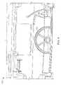
- FIG. 5Cillustrates a side view of the portable audio system 100 .
- the front surface 190 of the portable audio system 100is set to a predetermined angle 196 relative to a vertical plane 198 .
- the angle 196is 11.5 degrees. Other angles can also be used.
- the angleprovides an upward tilt to the front surface 190 of the portable audio system 100 .
- the angleprovides increased mechanical stability to the portable audio system 100 .
- an external audio sourcesuch as a MP3 player can include an angled base which causes the external audio source to lean at a different angle when inserted into the docking cradle 150 .
- the docking cradle 150can be independently tilted to maintain the angle specified by the manufacturer of the external audio source.
- a docking cradle adapter or insertcan be used having a shape that facilitates the proper positioning of the external audio device. For example, if the lean angle on an external audio device is 15.0 degrees and the lean angle of the portable audio system 100 is 11.5 degrees, that the docking cradle 150 can include a lean angle of 3.5 degrees to compensate for the difference.
- a bottom surface of the pocket 170 of the docking cradle 150 shown in FIG. 3can be oriented at any desired angle relative to the front surface 190 of the portable audio system 100 .
- FIG. 6Aillustrates a rear perspective view of a portable audio system 100 .
- the portable energy source 120is shown attached to the rear surface 192 of the housing 102 though the securing mechanism 122 .
- the audio input terminal 124is configured to accept an external audio source.
- the audio input terminal 124could be an RCA jack, a 3.5 mm jack, a digital input, or any other suitable connector.
- the input power connector 123receives DC voltage from an AC adapter. In another embodiment, the input power connector 123 can also be configured to receive AC power.
- the controllers 110 , 112are shown on the side surface 114 of the housing 102 .
- An open end 200 of a waveguide 202is also shown exiting the back surface 192 of the housing 102 .
- the open end 200can be shaped and sized to function as handle for the portable audio system 100 .
- a similar location and shapecan also be used for the exit of a port in a portable audio system utilizing a ported acoustic enclosure (not shown) instead of a waveguide.
- the opening for either waveguide or portcan generically be referred to as an acoustic exit.
- the open end 200can be shaped to facilitate the grasping of the housing 102 with multiple fingers from a human hand.
- the handlecan be used to move the portable audio system 100 .
- the waveguide 202includes a flare positioned at the acoustic exit 200 .
- the acoustic exit 200can also include a textured surface on an interior surface of the waveguide 202 .
- the textured surfaceprovides a griping surface for the fingers.
- the textured surfacecan be formed into the surface of the waveguide 202 .
- groovescan be engraved into the material in which the waveguide 202 is formed.
- a textured padcan be adhered to the interior surface of the waveguide 202 .
- the textured padcan include an abrasive sandpaper material. Other techniques for creating a textured surface can also be used.
- FIG. 6Billustrates another rear perspective view of the portable audio system 100 of FIG. 6A .
- One technique to carry the portable audio system 100is shown.
- One or more fingers 204 of a human hand 206are inserted into the acoustic exit 200 of the waveguide 202 .
- the thumb 208 of the hand 206can rest against the front surface 190 ( FIG. 5A ) of the portable audio system 100 .
- the thumb 208can rest against a top surface 210 of the portable audio system 100 .
- FIG. 7Ais a perspective view of a waveguide 250 according to one embodiment of the invention.
- the waveguide 250includes a first subsection 252 and a second subsection 254 .
- the first subsection 252bends around a first axis 256 and the second subsection 254 bends around a second axis 258 .
- the cross-sectional area of the waveguide 250can be in the shape of a rectangle including a long dimension 260 and a short dimension 262 .
- the waveguide turning around an axis parallel to the long dimensionhas been shown to reduce undesired noise as compared to turning around an axis parallel to the short dimension.
- the waveguide in the first subsection 252bends around the axis 256 parallel to the long dimension 260 and in the second subsection 254 bends around the axis 258 parallel to the long dimension 260 .
- the waveguide 250is shown having a substantially rectangular cross-section, any other suitable shape can also be used, such as an oval shape.
- the aspect ratios of the first subsection 252 and the second subsection 254may or may not be the same.
- the second axis 258is not parallel to the first axis 256 .
- the second axis 258lies in a plane that is perpendicular to the first axis 256 .
- each bendis a ninety degree bend.
- the magnitude of the bendcan be any desired amount.
- a third subsection 264acoustically couples the first subsection 252 to the second subsection 254 .
- the third subsection 264includes a first cross-sectional area having a first aspect ratio substantially matching that of the first subsection 252 .
- the third subsection 264includes a second cross-sectional area having a second aspect ratio substantially matching that of the second subsection 254 .
- the aspect ratio of the third subsection 264varies smoothly from the first aspect ratio to the second aspect ratio.
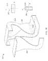
- FIG. 7Bis an exploded view of the waveguide 250 of FIG. 7A , illustrating a simple, easily moldable waveguide structure.
- the first aspect ratio 285 (cross section cut through the A-A′ plane) of the third subsection 264 and the second aspect ratio 286 (cross section cut through the B-B′ plane)are represented as cross sections having long and short dimension in the X-Y axis, with the long dimension in the X-axis at the first aspect ratio 285 and the long dimension in the Y-axis at the second aspect ratio 286 , whereby the X-axis and the Y-axis do not rotate in the transition from the first aspect ratio 285 to the second aspect ratio 286 but rather the dimension in the X-axis gradually changes from the long dimension to the short dimension and the dimension in the Y-axis simultaneously gradually changes from the short dimension to the long dimension.
- FIGS. 7A and 7Bproduces a structure that is easier to mold than the twisted waveguide.
- the cross sectional area of A-A′is the same as the cross sectional area of B-B′, the cross sectional area of the third subsection 264 should remain constant during its transition.
- the overall waveguidecomprises a changing cross sectional area according to a predetermined law related to position along the waveguide, that law should be maintained in the third subsection 264 during its transition from the first aspect ratio to the second aspect ratio.
- the waveguide 250is fabricated from multiple parts.
- the waveguide 250can be fabricated from a first part 280 and a second part 282 .
- the parts 280 , 282can be molded through known manufacturing techniques.
- the parts 280 , 282can be rigid structures formed by an injection molding process using a synthetic resin, such as LUSTRANTM 448 (Bayer Corporation, Elkhart, Ind.).
- the first part 280corresponds to a main body of the waveguide 250 and the second part 282 corresponds to a cover section.
- Part 280can be molded using simple tooling and with a single action in the molding machine.
- the two parts 280 , 282can be molded separately and then bonded together.
- Other techniques for fabricating the waveguide 250can also be used.
- FIG. 8is a perspective view of the interior of the portable audio system 100 illustrating a waveguide 300 .
- the waveguide 300can be described as a split waveguide structure which includes a trunk waveguide section 302 and two branch waveguide sections 304 a , 304 b . Junction ends 306 a , 306 b of the branch waveguide sections 304 a , 304 b are coupled to the trunk waveguide section 302 .
- the long dimension of the cross section of the open end at the top 308 of the trunkcan be oriented differently than the long dimension of the cross section at the junction end 310 .
- the trunk waveguide section 302This change in the orientation of the long dimension allows the trunk waveguide section 302 to bend around the short dimension 312 of its cross-sectional shape at the top 308 of the trunk waveguide section 302 .
- the aspect ratio at the junction end 310 of the trunk waveguide section 302can be different from the aspect ratio at the function end 310 of the trunk waveguide section 302 .
- Each of the branch waveguide sections 304 a , 304 bis wrapped around an empty cavity 314 a , 314 b .
- the cavities 314 a , 314 bare partially formed by two walls.
- a vent 316 along with the cavities 314 a , 314 bforms a resonant peak reducing mechanism. Since the waveguide is wrapped around a “double wall”, a large turning radius for the branch waveguide sections 304 a , 304 b is provided. Additionally, the volume and length of the cavities 314 a , 314 b can be chosen to reduce any undesired resonant peak due to the nature of the waveguide 300 .
- the housing 102includes the waveguide 300 having first left and right subsections 320 a , 320 b that contain left and right acoustic drivers 322 a , 322 b .
- the drivers 322 a , 322 beach include a radiating surface with a first side facing free air and a second side, opposite the first, facing into the hosing 102 and feeding acoustic waves into the branch waveguide sections 304 a , 304 b.
- Each branch waveguide section 304 a , 304 bis a folded continuous tube defining an interior passage and extending from one of the first left and right subsections 320 a , 320 b containing the drivers 322 a , 322 b at either end of the waveguide to a branch junction 324 .
- the trunk waveguide section 302extends from the branch junction 324 to a signal trunk opening 326 having a flared end.
- Each of the foldsdefines subsections within each branch waveguide section 304 a , 304 b .
- Each subsectionis bounded by baffles or panels extending from the front to the rear of the waveguide.
- the housing 102can also support other components such as an integrated MP3 player, a CD player, a radio, an AM antenna, an amplifier, and/or a power supply, for example.
- the first left and right subsections 320 a , 320 bare partially formed by the outside surfaces (facing the drivers) of tapered first panels 332 a , 332 b adjacent the drivers 322 a , 322 b and extend to the second subsections 334 a , 334 b .
- the second subsections 334 a , 334 bare formed by the inside surfaces (facing the trunk) waveguide section 302 ) of the tapered first panels 332 a , 332 b and an outside surface of second panels 336 a , 336 b and extend to the third subsection 338 a , 338 b.
- each of the panelsis a curved surface extending from the front or back of the waveguide and includes a free edge.
- a contoured post 340is formed at various free edges to reduce losses and turbulence of the acoustic pressure waves.
- the third subsections 338 a , 338 bare formed by the inside surfaces of the second panels 336 a , 336 b and the outside surface of third panels 342 a , 342 b .
- Left and right cavities 314 a , 314 bare formed by the inside surfaces of the third panels 342 a , 342 b and the outside surfaces of fourth panels 344 a , 344 b.
- the fourth subsections 346 a , 346 bare formed by the inside surfaces of the fourth panels 344 a , 344 b and the outside surface of the trunk waveguide section walls 348 a , 348 b and extend from the third subsections 338 a , 338 b to connect with the trunk waveguide section 302 at the branch junction 324 .
- each of the branch waveguide sections 304 a , 304 bcontinuously decreases along a path from the first left and right subsections 304 a , 304 b to the branch junction 324 .
- the first and second subsectionsare relatively large and can be more tapered compared with the third and fourth subsections and the common trunk waveguide section.
- the total volume and cross-sectional area profiles of the left and right branch waveguide sections 304 a , 304 bare similar.
- the left and right branch waveguide sections 304 a , 304 bcan be asymmetrical because of the need to accommodate the packaging of differently-sized electronic components within the housing 102 .
- the vent 316can be located proximate to the branch junction 324 .
- the vent 316connects the left and the right cavities 314 a , 314 b to the trunk waveguide section 302 .
- the left and right cavities 314 a , 314 bform acoustic structures that are sized and configured for reducing the magnitude of a resonance peak.
- the length of the left and right cavities 314 a , 314 bare chosen to exhibit a resonance behavior in the frequency range where it is desired to control the magnitude of a resonance peak in the waveguide.
- the left and right cavities 314 a , 314 bare designed such that the acoustic pressure due to the resonance in each cavity, that is present at the branch junction 324 , destructively interferes with the acoustic pressure within the waveguide 300 , thus reducing the peak magnitude.
- the location of the vent 316 and the cavities 314 a , 314 bare not limited to what has shown in FIG. 8 .
- the location of the cavitiescan be anywhere along a general waveguide system corresponding to the pressure maximum of the target standing wave and the particular resonance peak to be attenuated.
- the use of such cavities for damping out a resonance peakis not limited to waveguides having common trunk and branch section configuration.
- a target frequency component380 Hz in one example is significantly reduced.
- Resistive acoustical dampening materialscan be located proximate the vent 316 and/or in one or both of the cavities 314 a , 314 b .
- the cavities 314 a , 314 bcan also be bifurcated into multiple cavities for reducing multiple resonance peaks.
- any of the disclosed elementsmay be comprised of hardware portions (e.g., including discrete and integrated electronic circuitry), software portions (e.g., computer programming), and any combination thereof;
- f) hardware portionsmay be comprised of one or both of analog and digital portions
- any of the disclosed devices or portions thereofmay be combined together or separated into further portions unless specifically stated otherwise;
Landscapes
- Physics & Mathematics (AREA)
- Engineering & Computer Science (AREA)
- Acoustics & Sound (AREA)
- Signal Processing (AREA)
- Health & Medical Sciences (AREA)
- Otolaryngology (AREA)
- Telephone Set Structure (AREA)
- Details Of Audible-Bandwidth Transducers (AREA)
- Obtaining Desirable Characteristics In Audible-Bandwidth Transducers (AREA)
Abstract
Description
Claims (22)
Priority Applications (5)
| Application Number | Priority Date | Filing Date | Title |
|---|---|---|---|
| US11/615,674US7689197B2 (en) | 2006-12-22 | 2006-12-22 | Portable audio system with docking cradle |
| JP2007198060AJP5148942B2 (en) | 2006-12-22 | 2007-07-30 | Portable audio system with combined cradle |
| CNA2007101478720ACN101207391A (en) | 2006-12-22 | 2007-08-31 | Portable audio system with docking cradle |
| PCT/US2007/088520WO2008080044A2 (en) | 2006-12-22 | 2007-12-21 | Portable audio system with docking cradle |
| EP07869736.4AEP2092525B1 (en) | 2006-12-22 | 2007-12-21 | Portable audio system with docking cradle |
Applications Claiming Priority (1)
| Application Number | Priority Date | Filing Date | Title |
|---|---|---|---|
| US11/615,674US7689197B2 (en) | 2006-12-22 | 2006-12-22 | Portable audio system with docking cradle |
Publications (2)
| Publication Number | Publication Date |
|---|---|
| US20080152164A1 US20080152164A1 (en) | 2008-06-26 |
| US7689197B2true US7689197B2 (en) | 2010-03-30 |
Family
ID=39323000
Family Applications (1)
| Application Number | Title | Priority Date | Filing Date |
|---|---|---|---|
| US11/615,674Expired - Fee RelatedUS7689197B2 (en) | 2006-12-22 | 2006-12-22 | Portable audio system with docking cradle |
Country Status (5)
| Country | Link |
|---|---|
| US (1) | US7689197B2 (en) |
| EP (1) | EP2092525B1 (en) |
| JP (1) | JP5148942B2 (en) |
| CN (1) | CN101207391A (en) |
| WO (1) | WO2008080044A2 (en) |
Cited By (76)
| Publication number | Priority date | Publication date | Assignee | Title |
|---|---|---|---|---|
| US20090196441A1 (en)* | 2008-02-01 | 2009-08-06 | Hao-Chin Pai | Mp3 loudspeaker system |
| US20100149748A1 (en)* | 2008-12-11 | 2010-06-17 | Pak Wing Lam | Car multimedia device with ipod docking and ipod support bracket |
| US7885622B2 (en) | 2004-10-27 | 2011-02-08 | Chestnut Hill Sound Inc. | Entertainment system with bandless tuning |
| USD638031S1 (en)* | 2010-07-13 | 2011-05-17 | Samsung Electronics Co., Ltd. | Music player set |
| USD641007S1 (en)* | 2010-07-14 | 2011-07-05 | Sdi Technologies, Inc. | Wireless amplified speaker system |
| USD648320S1 (en)* | 2010-06-14 | 2011-11-08 | Sony Computer Entertainment Inc. | Speaker |
| US20120014056A1 (en)* | 2010-07-16 | 2012-01-19 | Jinsaun Chen | Rotating docking station for portable electronic devices |
| USD656483S1 (en)* | 2010-05-28 | 2012-03-27 | Roberts Radio Limited | Audio player with docking station |
| USD659119S1 (en)* | 2010-09-28 | 2012-05-08 | Beats Electronics, Llc | Audio speaker system |
| US20120140970A1 (en)* | 2010-12-07 | 2012-06-07 | Samsung Electronics Co. Ltd. | Docking station having structure for sound amplification and sound quality enhancement |
| US20120162877A1 (en)* | 2010-12-27 | 2012-06-28 | Seiko Epson Corporation | Projector |
| US20120293949A1 (en)* | 2011-05-20 | 2012-11-22 | Hon Hai Precision Industry Co., Ltd. | Docking station for electronic device |
| USD673930S1 (en)* | 2011-01-06 | 2013-01-08 | Koninklijke Philips Electronics N.V. | Speaker |
| USD673931S1 (en)* | 2011-01-06 | 2013-01-08 | Koninklijke Philips Electronics N.V. | Speaker |
| USD674775S1 (en)* | 2011-01-04 | 2013-01-22 | Koninklijke Philips Electronics N.V. | Speaker |
| USD674774S1 (en)* | 2011-01-04 | 2013-01-22 | Koninklijke Philips Electronics N.V. | Speaker |
| USD676418S1 (en)* | 2011-03-31 | 2013-02-19 | Pioneer Corporation | Speaker box with amplifier |
| USD676829S1 (en)* | 2011-01-05 | 2013-02-26 | Victor Company Of Japan, Limited | Speaker |
| USD677244S1 (en)* | 2011-03-31 | 2013-03-05 | Pioneer Corporation | Speaker box with amplifier |
| USD677245S1 (en)* | 2011-10-28 | 2013-03-05 | Sdi Technologies, Inc. | Portable media docking speaker system |
| USD677651S1 (en)* | 2011-12-16 | 2013-03-12 | Jwin Electronics Corp. | Robot docking speaker |
| USD678240S1 (en)* | 2011-05-03 | 2013-03-19 | Lg Electronics Inc. | Audio system |
| USD678862S1 (en)* | 2011-01-04 | 2013-03-26 | Koninklijke Philips Electronics N.V. | Speaker |
| USD678863S1 (en)* | 2011-12-08 | 2013-03-26 | Panasonic Corporation | Speaker with an amplifier |
| USD681005S1 (en)* | 2011-01-04 | 2013-04-30 | Koninklijke Philips Electronics N.V. | Speaker |
| USD681604S1 (en)* | 2011-03-31 | 2013-05-07 | Pioneer Corporation | Speaker box with amplifier |
| USD683718S1 (en)* | 2011-09-02 | 2013-06-04 | Beats Electronics, Llc | Audio speaker system |
| USD684560S1 (en)* | 2011-08-30 | 2013-06-18 | Lg Electronics Inc. | Docking speaker |
| USD687016S1 (en) | 2012-01-09 | 2013-07-30 | Beats Electronics, Llc | Audio speaker system |
| USD687013S1 (en)* | 2011-09-02 | 2013-07-30 | Lg Electronics Inc. | Docking speaker |
| USD687012S1 (en)* | 2011-09-02 | 2013-07-30 | Lg Electronics Inc. | Docking speaker |
| USD687011S1 (en)* | 2011-01-04 | 2013-07-30 | Koninklijke Philips N.V. | Speaker |
| USD688229S1 (en)* | 2011-11-11 | 2013-08-20 | Lg Electronics Inc. | Speaker dock for hand-held terminals |
| USD688227S1 (en)* | 2012-01-09 | 2013-08-20 | Monster, Llc | Docking station |
| USD688228S1 (en)* | 2011-11-11 | 2013-08-20 | Lg Electronics Inc. | Speaker dock for hand-held terminals |
| US20130219098A1 (en)* | 2011-07-11 | 2013-08-22 | Rpt Communications Inc. | Mobile Device Docking Station |
| USD689038S1 (en)* | 2012-03-07 | 2013-09-03 | Sdi Technologies, Inc. | Portable media player speaker system with sliding cover |
| USD689844S1 (en)* | 2012-01-05 | 2013-09-17 | D&M Europe B.V. | Sound dock |
| USD690280S1 (en) | 2012-01-09 | 2013-09-24 | Imation Corp. | Combined audio player and speaker |
| USD691585S1 (en)* | 2012-01-09 | 2013-10-15 | Imation Corp. | Speaker frame system |
| USD692856S1 (en)* | 2012-08-17 | 2013-11-05 | Sdi Technologies, Inc. | Rechargeable portable speaker system |
| USD693328S1 (en)* | 2011-11-09 | 2013-11-12 | Sony Corporation | Speaker box |
| USD694736S1 (en)* | 2012-06-20 | 2013-12-03 | Dexin Ming Electronics (Shenzhen) Co. Ltd. | Sound system |
| USD695268S1 (en)* | 2012-02-15 | 2013-12-10 | Sdi Technologies, Inc. | Rechargeable docking speaker system |
| USD695705S1 (en)* | 2011-12-13 | 2013-12-17 | Sony Corporation | Audio player |
| USD697898S1 (en)* | 2012-04-30 | 2014-01-21 | Samsung Electronics Co., Ltd. | Speaker docking station |
| USD702211S1 (en)* | 2012-04-24 | 2014-04-08 | Samsung Electronics Co., Ltd. | Docking audio |
| USD702663S1 (en)* | 2012-06-29 | 2014-04-15 | Samsung Electronics Co., Ltd. | Docking audio |
| USD703185S1 (en)* | 2012-04-24 | 2014-04-22 | Samsung Electronics Co., Ltd. | Docking audio |
| USD703191S1 (en)* | 2012-09-25 | 2014-04-22 | Lg Electronics Inc. | Speaker |
| USD707656S1 (en) | 2013-01-03 | 2014-06-24 | Beats Electronics, Llc | Audio speaker system |
| USD709481S1 (en)* | 2013-04-19 | 2014-07-22 | Li-hsing LIU | Speaker |
| USD713380S1 (en)* | 2013-07-03 | 2014-09-16 | Lg Electronics Inc. | Audio |
| US20140281096A1 (en)* | 2013-03-14 | 2014-09-18 | G-Tek Electronics Corporation | Broadcasting device with communication mechanism |
| US8867776B2 (en) | 2012-01-09 | 2014-10-21 | Imation Corp. | Audio speaker frame for multimedia device |
| US20140340029A1 (en)* | 2013-05-14 | 2014-11-20 | Hon Hai Precision Industry Co., Ltd. | Charger with hub |
| USD718736S1 (en) | 2012-01-09 | 2014-12-02 | Imation Corp. | Audio player and speaker system |
| US20150019783A1 (en)* | 2005-08-01 | 2015-01-15 | Universal Electronics Inc. | System and method for accessing a user interface via a secondary device |
| US20150096828A1 (en)* | 2013-10-07 | 2015-04-09 | Incipio Technologies, Inc. | Audio speaker with externally reinforced passive radiator attachment |
| USD728515S1 (en)* | 2013-05-30 | 2015-05-05 | Samsung Electronics Co., Ltd. | Audio device with docking station |
| US9071906B2 (en) | 2012-01-09 | 2015-06-30 | Imation Corp. | Wireless audio player and speaker system |
| US9143861B2 (en) | 2012-01-09 | 2015-09-22 | Imation Corp. | Wireless audio player and speaker system |
| USD754635S1 (en)* | 2014-10-15 | 2016-04-26 | Hon Hai Precision Industry Co., Ltd. | Speaker in the shape of an auto glass |
| US20160127830A1 (en)* | 2009-12-31 | 2016-05-05 | Slotius, Llc | Self-powered audio speaker having socket for audio data receiver |
| USD755756S1 (en) | 2013-01-03 | 2016-05-10 | Apple Inc. | Audio speaker system |
| USD763823S1 (en)* | 2014-07-10 | 2016-08-16 | Sdi Technologies, Inc. | Rechargeable stereo speaker system with removable battery charger |
| USD768598S1 (en)* | 2015-06-26 | 2016-10-11 | Greenwave Scientific, Inc. | Media player |
| USD792375S1 (en)* | 2015-09-03 | 2017-07-18 | Bose Corporation | Speaker |
| US9778896B2 (en) | 2011-10-21 | 2017-10-03 | Sonos, Inc. | Wireless music playback |
| US20180131119A1 (en)* | 2006-11-09 | 2018-05-10 | The Wiremold Company | Electrical pop out device |
| USD868742S1 (en)* | 2018-06-07 | 2019-12-03 | Dongguan Leshi Electronic & Technology Co., Ltd | Headphone adapter |
| US10601973B1 (en)* | 2019-03-19 | 2020-03-24 | Balaji Raghunathan | Multiple connector electronics docking device |
| USD896195S1 (en)* | 2017-09-20 | 2020-09-15 | Yealink (Xiamen) Network Technology Co., Ltd. | Video network conference telephone apparatus |
| US11068028B1 (en)* | 2020-01-05 | 2021-07-20 | Lenovo (Singapore) Pte. Ltd. | Device dock |
| US11126397B2 (en) | 2004-10-27 | 2021-09-21 | Chestnut Hill Sound, Inc. | Music audio control and distribution system in a location |
| USD958113S1 (en) | 2014-05-25 | 2022-07-19 | Apple Inc. | Audio speaker system |
Families Citing this family (5)
| Publication number | Priority date | Publication date | Assignee | Title |
|---|---|---|---|---|
| US7913020B2 (en)* | 2008-04-29 | 2011-03-22 | Bose Corporation | Automated exchangeable docking configuration |
| EP2329700A4 (en)* | 2008-09-25 | 2012-08-15 | Coby Electronics Corp | Docking station with rotation mechanism |
| JP5857271B2 (en)* | 2011-12-09 | 2016-02-10 | パナソニックIpマネジメント株式会社 | Music player |
| US9351060B2 (en) | 2014-02-14 | 2016-05-24 | Sonic Blocks, Inc. | Modular quick-connect A/V system and methods thereof |
| US20150281815A1 (en)* | 2014-03-31 | 2015-10-01 | Bose Corporation | Accessory Shelf |
Citations (25)
| Publication number | Priority date | Publication date | Assignee | Title |
|---|---|---|---|---|
| US4468836A (en) | 1980-11-27 | 1984-09-04 | Nifco Inc. | Door dampening mechanism having a non-rotatable vane |
| US4628528A (en) | 1982-09-29 | 1986-12-09 | Bose Corporation | Pressure wave transducing |
| US5099995A (en)* | 1988-11-14 | 1992-03-31 | Teac Corporation | Disc housing case |
| US5836496A (en)* | 1997-06-06 | 1998-11-17 | Ford Motor Company | Vehicle cellular phone presentation device |
| JPH11202973A (en)* | 1998-01-08 | 1999-07-30 | Nec Corp | Storage structure of speaker |
| US20010001083A1 (en) | 1999-06-25 | 2001-05-10 | Helot Jacques H. | Docking station for multiple devices |
| US6278789B1 (en) | 1993-05-06 | 2001-08-21 | Bose Corporation | Frequency selective acoustic waveguide damping |
| US6366450B1 (en) | 1999-12-09 | 2002-04-02 | Gateway, Inc. | Hideaway integrated docking cradle |
| US6567677B1 (en)* | 2000-08-14 | 2003-05-20 | Seth David Sokoloff | Notebook computer-telephone |
| US20050053365A1 (en)* | 1997-10-06 | 2005-03-10 | Adams Dale R. | Portable DVD player |
| US6874626B2 (en)* | 1999-04-16 | 2005-04-05 | Diskjocki | Disc holder |
| US20050094837A1 (en) | 2003-10-31 | 2005-05-05 | Parker Robert P. | Porting |
| US20050105754A1 (en)* | 2002-04-30 | 2005-05-19 | Esmail Amid-Hozour | Portable audio player |
| US20050265569A1 (en)* | 2004-04-30 | 2005-12-01 | Altec Lansing Technologies, Inc. | Compact portable media reproduction system |
| US20060046780A1 (en)* | 2004-09-01 | 2006-03-02 | Venkat Subramaniam | Audio system for portable device |
| US7095867B2 (en)* | 2004-04-30 | 2006-08-22 | Altec Lansing Technologies, Inc. | Portable audio reproduction system |
| US20060238164A1 (en)* | 2005-04-22 | 2006-10-26 | Kyocera Wireless Corp. | Desktop charger for a portable electronic device with a display |
| US20060274910A1 (en)* | 2005-06-03 | 2006-12-07 | Altec Lansing Technologies, Inc. | Portable media reproduction system |
| US20070047198A1 (en)* | 2005-08-24 | 2007-03-01 | Apple Computer, Inc. A California Corporation | Docking station for hand held electronic devices |
| USD560208S1 (en)* | 2006-12-12 | 2008-01-22 | Sdi Technologies Inc. | Amplified speakers with alarm clock |
| USD563431S1 (en)* | 2006-08-08 | 2008-03-04 | Lifepod Llc | Carrying case with integrated speaker system and portable media player with control window |
| US20080089547A1 (en) | 2006-10-13 | 2008-04-17 | Klipsch, Llc | Digital audio speaker system for digital audio players with motorized drawer mechanism |
| US20080152181A1 (en)* | 2006-12-22 | 2008-06-26 | Robert Preston Parker | Portable audio system having waveguide structure |
| USD583356S1 (en)* | 2007-04-10 | 2008-12-23 | Plantronics, Inc. | Speaker system for portable media player |
| US7469951B2 (en)* | 2006-02-23 | 2008-12-30 | Leopold Kostal Gmbh & Co. Kg | Device holder for fitting in a motor vehicle |
Family Cites Families (4)
| Publication number | Priority date | Publication date | Assignee | Title |
|---|---|---|---|---|
| JPS63204544A (en)* | 1987-02-19 | 1988-08-24 | Matsushita Commun Ind Co Ltd | Cartridge ejecting device |
| JP2505034B2 (en)* | 1988-11-25 | 1996-06-05 | 株式会社イトーキクレビオ | Draft chamber |
| JPH07287911A (en)* | 1994-04-20 | 1995-10-31 | Fujitsu General Ltd | Optical drive loading mechanism |
| KR100238273B1 (en)* | 1996-12-31 | 2000-02-01 | 윤종용 | Disk player |
- 2006
- 2006-12-22USUS11/615,674patent/US7689197B2/ennot_activeExpired - Fee Related
- 2007
- 2007-07-30JPJP2007198060Apatent/JP5148942B2/ennot_activeExpired - Fee Related
- 2007-08-31CNCNA2007101478720Apatent/CN101207391A/enactivePending
- 2007-12-21EPEP07869736.4Apatent/EP2092525B1/ennot_activeNot-in-force
- 2007-12-21WOPCT/US2007/088520patent/WO2008080044A2/enactiveApplication Filing
Patent Citations (25)
| Publication number | Priority date | Publication date | Assignee | Title |
|---|---|---|---|---|
| US4468836A (en) | 1980-11-27 | 1984-09-04 | Nifco Inc. | Door dampening mechanism having a non-rotatable vane |
| US4628528A (en) | 1982-09-29 | 1986-12-09 | Bose Corporation | Pressure wave transducing |
| US5099995A (en)* | 1988-11-14 | 1992-03-31 | Teac Corporation | Disc housing case |
| US6278789B1 (en) | 1993-05-06 | 2001-08-21 | Bose Corporation | Frequency selective acoustic waveguide damping |
| US5836496A (en)* | 1997-06-06 | 1998-11-17 | Ford Motor Company | Vehicle cellular phone presentation device |
| US20050053365A1 (en)* | 1997-10-06 | 2005-03-10 | Adams Dale R. | Portable DVD player |
| JPH11202973A (en)* | 1998-01-08 | 1999-07-30 | Nec Corp | Storage structure of speaker |
| US6874626B2 (en)* | 1999-04-16 | 2005-04-05 | Diskjocki | Disc holder |
| US20010001083A1 (en) | 1999-06-25 | 2001-05-10 | Helot Jacques H. | Docking station for multiple devices |
| US6366450B1 (en) | 1999-12-09 | 2002-04-02 | Gateway, Inc. | Hideaway integrated docking cradle |
| US6567677B1 (en)* | 2000-08-14 | 2003-05-20 | Seth David Sokoloff | Notebook computer-telephone |
| US20050105754A1 (en)* | 2002-04-30 | 2005-05-19 | Esmail Amid-Hozour | Portable audio player |
| US20050094837A1 (en) | 2003-10-31 | 2005-05-05 | Parker Robert P. | Porting |
| US20050265569A1 (en)* | 2004-04-30 | 2005-12-01 | Altec Lansing Technologies, Inc. | Compact portable media reproduction system |
| US7095867B2 (en)* | 2004-04-30 | 2006-08-22 | Altec Lansing Technologies, Inc. | Portable audio reproduction system |
| US20060046780A1 (en)* | 2004-09-01 | 2006-03-02 | Venkat Subramaniam | Audio system for portable device |
| US20060238164A1 (en)* | 2005-04-22 | 2006-10-26 | Kyocera Wireless Corp. | Desktop charger for a portable electronic device with a display |
| US20060274910A1 (en)* | 2005-06-03 | 2006-12-07 | Altec Lansing Technologies, Inc. | Portable media reproduction system |
| US20070047198A1 (en)* | 2005-08-24 | 2007-03-01 | Apple Computer, Inc. A California Corporation | Docking station for hand held electronic devices |
| US7469951B2 (en)* | 2006-02-23 | 2008-12-30 | Leopold Kostal Gmbh & Co. Kg | Device holder for fitting in a motor vehicle |
| USD563431S1 (en)* | 2006-08-08 | 2008-03-04 | Lifepod Llc | Carrying case with integrated speaker system and portable media player with control window |
| US20080089547A1 (en) | 2006-10-13 | 2008-04-17 | Klipsch, Llc | Digital audio speaker system for digital audio players with motorized drawer mechanism |
| USD560208S1 (en)* | 2006-12-12 | 2008-01-22 | Sdi Technologies Inc. | Amplified speakers with alarm clock |
| US20080152181A1 (en)* | 2006-12-22 | 2008-06-26 | Robert Preston Parker | Portable audio system having waveguide structure |
| USD583356S1 (en)* | 2007-04-10 | 2008-12-23 | Plantronics, Inc. | Speaker system for portable media player |
Non-Patent Citations (7)
| Title |
|---|
| Altec Lansing® inMotion Mobile Audio, "Mobile Speaker system for your iPod®" iM5. Sep. 2005. |
| Altec Lansing® inMotion Portable Audio, "un-plugged" iM3. Jun. 2005. |
| Altec Lansing® inMotion Portable Audio, "un-plugged" iM7. Jan. 2006. |
| English Translation received Oct. 27, 2009 for Japanese Patent Application JP11-202973 cited by Examiner as a reference in Jul. 21, 2009 Non-Final Office Action in U.S. Appl. No. 11/615,674. |
| International Preliminary Report on Patentability dated Feb. 18, 2009 for PCT/US07/088520. |
| International Search Report and Written Opinion dated Aug. 8, 2008 for PCT Appl. No. PCT/US2007/088520. |
| Invitation to Pay Additional Fees dated May 27, 2008 from International Application No. PCT/US2007/088520. |
Cited By (105)
| Publication number | Priority date | Publication date | Assignee | Title |
|---|---|---|---|---|
| US8195114B2 (en) | 2004-10-27 | 2012-06-05 | Chestnut Hill Sound, Inc. | Entertainment system with bandless content selection |
| US20110072050A1 (en)* | 2004-10-27 | 2011-03-24 | Chestnut Hill Sound, Inc. | Accessing digital media content via metadata |
| US7885622B2 (en) | 2004-10-27 | 2011-02-08 | Chestnut Hill Sound Inc. | Entertainment system with bandless tuning |
| US20110069433A1 (en)* | 2004-10-27 | 2011-03-24 | Chestnut Hill Sound, Inc. | Media appliance with auxiliary source module |
| US20110070777A1 (en)* | 2004-10-27 | 2011-03-24 | Chestnut Hill Sound, Inc. | Electrical connector adaptor system for media devices |
| US20110072347A1 (en)* | 2004-10-27 | 2011-03-24 | Chestnut Hill Sound, Inc. | Entertainment system with remote control |
| US20110069844A1 (en)* | 2004-10-27 | 2011-03-24 | Krampf Steven S | Entertainment system with bandless content selection |
| US20110071658A1 (en)* | 2004-10-27 | 2011-03-24 | Chestnut Hill Sound, Inc. | Media appliance with docking |
| US10114608B2 (en) | 2004-10-27 | 2018-10-30 | Chestnut Hill Sound, Inc. | Multi-mode media device operable in first and second modes, selectively |
| US20110070757A1 (en)* | 2004-10-27 | 2011-03-24 | Chestnut Hill Sound, Inc. | Electrical and mechanical connector adaptor system for media devices |
| US8725063B2 (en) | 2004-10-27 | 2014-05-13 | Chestnut Hill Sound, Inc. | Multi-mode media device using metadata to access media content |
| US8355690B2 (en) | 2004-10-27 | 2013-01-15 | Chestnut Hill Sound, Inc. | Electrical and mechanical connector adaptor system for media devices |
| US8843092B2 (en) | 2004-10-27 | 2014-09-23 | Chestnut Hill Sound, Inc. | Method and apparatus for accessing media content via metadata |
| US11126397B2 (en) | 2004-10-27 | 2021-09-21 | Chestnut Hill Sound, Inc. | Music audio control and distribution system in a location |
| US12353669B2 (en) | 2005-08-01 | 2025-07-08 | Universal Electronics Inc. | System and method for accessing a user interface via a secondary device |
| US10656774B2 (en) | 2005-08-01 | 2020-05-19 | Universal Electronics Inc. | System and method for accessing a user interface via a secondary device |
| US20150019783A1 (en)* | 2005-08-01 | 2015-01-15 | Universal Electronics Inc. | System and method for accessing a user interface via a secondary device |
| US9558141B2 (en)* | 2005-08-01 | 2017-01-31 | Universal Electronics Inc. | System and method for accessing a user interface via a secondary device |
| US20180131119A1 (en)* | 2006-11-09 | 2018-05-10 | The Wiremold Company | Electrical pop out device |
| US11038298B2 (en)* | 2006-11-09 | 2021-06-15 | The Wiremold Company | Electrical pop out device |
| US20090196441A1 (en)* | 2008-02-01 | 2009-08-06 | Hao-Chin Pai | Mp3 loudspeaker system |
| US20100149748A1 (en)* | 2008-12-11 | 2010-06-17 | Pak Wing Lam | Car multimedia device with ipod docking and ipod support bracket |
| US20160127830A1 (en)* | 2009-12-31 | 2016-05-05 | Slotius, Llc | Self-powered audio speaker having socket for audio data receiver |
| USD656483S1 (en)* | 2010-05-28 | 2012-03-27 | Roberts Radio Limited | Audio player with docking station |
| USD648320S1 (en)* | 2010-06-14 | 2011-11-08 | Sony Computer Entertainment Inc. | Speaker |
| USD638031S1 (en)* | 2010-07-13 | 2011-05-17 | Samsung Electronics Co., Ltd. | Music player set |
| USD641007S1 (en)* | 2010-07-14 | 2011-07-05 | Sdi Technologies, Inc. | Wireless amplified speaker system |
| US20120014056A1 (en)* | 2010-07-16 | 2012-01-19 | Jinsaun Chen | Rotating docking station for portable electronic devices |
| USD659119S1 (en)* | 2010-09-28 | 2012-05-08 | Beats Electronics, Llc | Audio speaker system |
| US8483420B2 (en)* | 2010-12-07 | 2013-07-09 | Samsung Electronics Co., Ltd. | Docking station having structure for sound amplification and sound quality enhancement |
| US9100751B2 (en) | 2010-12-07 | 2015-08-04 | Samsung Electronics Co., Ltd. | Docking station having structure for sound amplification and sound quality enhancement |
| US20120140970A1 (en)* | 2010-12-07 | 2012-06-07 | Samsung Electronics Co. Ltd. | Docking station having structure for sound amplification and sound quality enhancement |
| US20120162877A1 (en)* | 2010-12-27 | 2012-06-28 | Seiko Epson Corporation | Projector |
| US8780547B2 (en)* | 2010-12-27 | 2014-07-15 | Seiko Epson Corporation | Projector |
| USD674774S1 (en)* | 2011-01-04 | 2013-01-22 | Koninklijke Philips Electronics N.V. | Speaker |
| USD674775S1 (en)* | 2011-01-04 | 2013-01-22 | Koninklijke Philips Electronics N.V. | Speaker |
| USD678862S1 (en)* | 2011-01-04 | 2013-03-26 | Koninklijke Philips Electronics N.V. | Speaker |
| USD681005S1 (en)* | 2011-01-04 | 2013-04-30 | Koninklijke Philips Electronics N.V. | Speaker |
| USD687011S1 (en)* | 2011-01-04 | 2013-07-30 | Koninklijke Philips N.V. | Speaker |
| USD676829S1 (en)* | 2011-01-05 | 2013-02-26 | Victor Company Of Japan, Limited | Speaker |
| USD673930S1 (en)* | 2011-01-06 | 2013-01-08 | Koninklijke Philips Electronics N.V. | Speaker |
| USD673931S1 (en)* | 2011-01-06 | 2013-01-08 | Koninklijke Philips Electronics N.V. | Speaker |
| USD677244S1 (en)* | 2011-03-31 | 2013-03-05 | Pioneer Corporation | Speaker box with amplifier |
| USD676418S1 (en)* | 2011-03-31 | 2013-02-19 | Pioneer Corporation | Speaker box with amplifier |
| USD681604S1 (en)* | 2011-03-31 | 2013-05-07 | Pioneer Corporation | Speaker box with amplifier |
| USD678240S1 (en)* | 2011-05-03 | 2013-03-19 | Lg Electronics Inc. | Audio system |
| US20120293949A1 (en)* | 2011-05-20 | 2012-11-22 | Hon Hai Precision Industry Co., Ltd. | Docking station for electronic device |
| US8780546B2 (en)* | 2011-05-20 | 2014-07-15 | Fu Tai Hua Industry (Shenzhen) Co., Ltd. | Docking station for electronic device |
| US20130219098A1 (en)* | 2011-07-11 | 2013-08-22 | Rpt Communications Inc. | Mobile Device Docking Station |
| USD684560S1 (en)* | 2011-08-30 | 2013-06-18 | Lg Electronics Inc. | Docking speaker |
| USD687013S1 (en)* | 2011-09-02 | 2013-07-30 | Lg Electronics Inc. | Docking speaker |
| USD687012S1 (en)* | 2011-09-02 | 2013-07-30 | Lg Electronics Inc. | Docking speaker |
| USD683718S1 (en)* | 2011-09-02 | 2013-06-04 | Beats Electronics, Llc | Audio speaker system |
| US9778896B2 (en) | 2011-10-21 | 2017-10-03 | Sonos, Inc. | Wireless music playback |
| USD677245S1 (en)* | 2011-10-28 | 2013-03-05 | Sdi Technologies, Inc. | Portable media docking speaker system |
| USD693328S1 (en)* | 2011-11-09 | 2013-11-12 | Sony Corporation | Speaker box |
| USD688228S1 (en)* | 2011-11-11 | 2013-08-20 | Lg Electronics Inc. | Speaker dock for hand-held terminals |
| USD688229S1 (en)* | 2011-11-11 | 2013-08-20 | Lg Electronics Inc. | Speaker dock for hand-held terminals |
| USD678863S1 (en)* | 2011-12-08 | 2013-03-26 | Panasonic Corporation | Speaker with an amplifier |
| USD695705S1 (en)* | 2011-12-13 | 2013-12-17 | Sony Corporation | Audio player |
| USD677651S1 (en)* | 2011-12-16 | 2013-03-12 | Jwin Electronics Corp. | Robot docking speaker |
| USD689844S1 (en)* | 2012-01-05 | 2013-09-17 | D&M Europe B.V. | Sound dock |
| USD755161S1 (en) | 2012-01-09 | 2016-05-03 | Apple Inc. | Audio speaker system |
| USD691585S1 (en)* | 2012-01-09 | 2013-10-15 | Imation Corp. | Speaker frame system |
| USD690280S1 (en) | 2012-01-09 | 2013-09-24 | Imation Corp. | Combined audio player and speaker |
| USD709861S1 (en) | 2012-01-09 | 2014-07-29 | Beats Electronics, Llc | Audio speaker system |
| USD959410S1 (en) | 2012-01-09 | 2022-08-02 | Apple Inc. | Audio speaker system |
| USD842276S1 (en) | 2012-01-09 | 2019-03-05 | Apple Inc. | Audio speaker system |
| USD688227S1 (en)* | 2012-01-09 | 2013-08-20 | Monster, Llc | Docking station |
| US8867776B2 (en) | 2012-01-09 | 2014-10-21 | Imation Corp. | Audio speaker frame for multimedia device |
| US9143861B2 (en) | 2012-01-09 | 2015-09-22 | Imation Corp. | Wireless audio player and speaker system |
| USD718736S1 (en) | 2012-01-09 | 2014-12-02 | Imation Corp. | Audio player and speaker system |
| USD687016S1 (en) | 2012-01-09 | 2013-07-30 | Beats Electronics, Llc | Audio speaker system |
| US9071906B2 (en) | 2012-01-09 | 2015-06-30 | Imation Corp. | Wireless audio player and speaker system |
| USD695268S1 (en)* | 2012-02-15 | 2013-12-10 | Sdi Technologies, Inc. | Rechargeable docking speaker system |
| USD689038S1 (en)* | 2012-03-07 | 2013-09-03 | Sdi Technologies, Inc. | Portable media player speaker system with sliding cover |
| USD702211S1 (en)* | 2012-04-24 | 2014-04-08 | Samsung Electronics Co., Ltd. | Docking audio |
| USD703185S1 (en)* | 2012-04-24 | 2014-04-22 | Samsung Electronics Co., Ltd. | Docking audio |
| USD697898S1 (en)* | 2012-04-30 | 2014-01-21 | Samsung Electronics Co., Ltd. | Speaker docking station |
| USD694736S1 (en)* | 2012-06-20 | 2013-12-03 | Dexin Ming Electronics (Shenzhen) Co. Ltd. | Sound system |
| USD702663S1 (en)* | 2012-06-29 | 2014-04-15 | Samsung Electronics Co., Ltd. | Docking audio |
| USD692856S1 (en)* | 2012-08-17 | 2013-11-05 | Sdi Technologies, Inc. | Rechargeable portable speaker system |
| USD703191S1 (en)* | 2012-09-25 | 2014-04-22 | Lg Electronics Inc. | Speaker |
| USD755757S1 (en) | 2013-01-03 | 2016-05-10 | Apple Inc. | Audio speaker system |
| USD707656S1 (en) | 2013-01-03 | 2014-06-24 | Beats Electronics, Llc | Audio speaker system |
| USD755756S1 (en) | 2013-01-03 | 2016-05-10 | Apple Inc. | Audio speaker system |
| US20140281096A1 (en)* | 2013-03-14 | 2014-09-18 | G-Tek Electronics Corporation | Broadcasting device with communication mechanism |
| USD709481S1 (en)* | 2013-04-19 | 2014-07-22 | Li-hsing LIU | Speaker |
| US9893541B2 (en)* | 2013-05-14 | 2018-02-13 | Ambit Microsystems (Shanghai) Ltd. | Charger with hub |
| US20140340029A1 (en)* | 2013-05-14 | 2014-11-20 | Hon Hai Precision Industry Co., Ltd. | Charger with hub |
| USD728515S1 (en)* | 2013-05-30 | 2015-05-05 | Samsung Electronics Co., Ltd. | Audio device with docking station |
| USD713380S1 (en)* | 2013-07-03 | 2014-09-16 | Lg Electronics Inc. | Audio |
| US10390128B2 (en) | 2013-10-07 | 2019-08-20 | Zagg Amplified, Inc. | Audio speaker with externally reinforced passive radiator attachment |
| US20150096828A1 (en)* | 2013-10-07 | 2015-04-09 | Incipio Technologies, Inc. | Audio speaker with externally reinforced passive radiator attachment |
| US9271098B2 (en)* | 2013-10-07 | 2016-02-23 | Incipio Technologies, Inc. | Audio speaker with externally reinforced passive radiator attachment |
| USD1024017S1 (en) | 2014-05-25 | 2024-04-23 | Apple Inc. | Audio speaker system |
| USD958113S1 (en) | 2014-05-25 | 2022-07-19 | Apple Inc. | Audio speaker system |
| USD763823S1 (en)* | 2014-07-10 | 2016-08-16 | Sdi Technologies, Inc. | Rechargeable stereo speaker system with removable battery charger |
| USD754635S1 (en)* | 2014-10-15 | 2016-04-26 | Hon Hai Precision Industry Co., Ltd. | Speaker in the shape of an auto glass |
| USD768598S1 (en)* | 2015-06-26 | 2016-10-11 | Greenwave Scientific, Inc. | Media player |
| USD792375S1 (en)* | 2015-09-03 | 2017-07-18 | Bose Corporation | Speaker |
| USD896195S1 (en)* | 2017-09-20 | 2020-09-15 | Yealink (Xiamen) Network Technology Co., Ltd. | Video network conference telephone apparatus |
| USD868742S1 (en)* | 2018-06-07 | 2019-12-03 | Dongguan Leshi Electronic & Technology Co., Ltd | Headphone adapter |
| US10601973B1 (en)* | 2019-03-19 | 2020-03-24 | Balaji Raghunathan | Multiple connector electronics docking device |
| US11068028B1 (en)* | 2020-01-05 | 2021-07-20 | Lenovo (Singapore) Pte. Ltd. | Device dock |
Also Published As
| Publication number | Publication date |
|---|---|
| JP5148942B2 (en) | 2013-02-20 |
| EP2092525B1 (en) | 2013-08-28 |
| US20080152164A1 (en) | 2008-06-26 |
| JP2008160794A (en) | 2008-07-10 |
| WO2008080044A3 (en) | 2008-10-09 |
| WO2008080044A2 (en) | 2008-07-03 |
| EP2092525A2 (en) | 2009-08-26 |
| CN101207391A (en) | 2008-06-25 |
Similar Documents
| Publication | Publication Date | Title |
|---|---|---|
| US10097911B2 (en) | Audio system having integral handle | |
| US7689197B2 (en) | Portable audio system with docking cradle | |
| US8320597B2 (en) | Acoustic dock for portable electronic device | |
| US7280802B2 (en) | FM transmitter and power supply/charging assembly for MP3 player | |
| US20080053770A1 (en) | Travel case for a portable electronic device | |
| US20050014536A1 (en) | Modular adaptor assembly for personal digital appliance | |
| US20090114550A1 (en) | Eyeglass speaker case | |
| WO2004008649A1 (en) | Modular adaptor assembly for personal digital appliance | |
| HK1127462B (en) | Portable audio system having waveguide structure | |
| HK1120679A (en) | Portable audio system with docking cradle | |
| CN209845208U (en) | Vibration-proof sound box | |
| JP2023129185A (en) | display device |
Legal Events
| Date | Code | Title | Description |
|---|---|---|---|
| AS | Assignment | Owner name:BOSE CORPORATION, MASSACHUSETTS Free format text:ASSIGNMENT OF ASSIGNORS INTEREST;ASSIGNORS:LAUDE, MICHAEL E.;RATCLIFFE, CHRISTOPHER;STALLER, NORMON D.;AND OTHERS;REEL/FRAME:018892/0355;SIGNING DATES FROM 20070205 TO 20070213 Owner name:BOSE CORPORATION,MASSACHUSETTS Free format text:ASSIGNMENT OF ASSIGNORS INTEREST;ASSIGNORS:LAUDE, MICHAEL E.;RATCLIFFE, CHRISTOPHER;STALLER, NORMON D.;AND OTHERS;SIGNING DATES FROM 20070205 TO 20070213;REEL/FRAME:018892/0355 | |
| AS | Assignment | Owner name:BOSE CORPORATION, MASSACHUSETTS Free format text:CORRECTIVE ASSIGNMENT TO CORRECT THE ASSIGNEE'S NAME PREVIOUSLY RECORDED ON REEL 018892 FRAME 0355;ASSIGNORS:LAUDE, MICHAEL E.;RATCLIFFE, CHRISTOPHER;STALLER, NORMAN D.;AND OTHERS;REEL/FRAME:018967/0777;SIGNING DATES FROM 20070205 TO 20070213 Owner name:BOSE CORPORATION,MASSACHUSETTS Free format text:CORRECTIVE ASSIGNMENT TO CORRECT THE ASSIGNEE'S NAME PREVIOUSLY RECORDED ON REEL 018892 FRAME 0355. ASSIGNOR(S) HEREBY CONFIRMS THE ASSIGNEE'S NAME SHOULD BE CHANGED FROM "NORMON D. STALLER" TO --NORMAN D. STALLER--;ASSIGNORS:LAUDE, MICHAEL E.;RATCLIFFE, CHRISTOPHER;STALLER, NORMAN D.;AND OTHERS;SIGNING DATES FROM 20070205 TO 20070213;REEL/FRAME:018967/0777 | |
| STCF | Information on status: patent grant | Free format text:PATENTED CASE | |
| FPAY | Fee payment | Year of fee payment:4 | |
| MAFP | Maintenance fee payment | Free format text:PAYMENT OF MAINTENANCE FEE, 8TH YEAR, LARGE ENTITY (ORIGINAL EVENT CODE: M1552) Year of fee payment:8 | |
| FEPP | Fee payment procedure | Free format text:MAINTENANCE FEE REMINDER MAILED (ORIGINAL EVENT CODE: REM.); ENTITY STATUS OF PATENT OWNER: LARGE ENTITY | |
| LAPS | Lapse for failure to pay maintenance fees | Free format text:PATENT EXPIRED FOR FAILURE TO PAY MAINTENANCE FEES (ORIGINAL EVENT CODE: EXP.); ENTITY STATUS OF PATENT OWNER: LARGE ENTITY | |
| STCH | Information on status: patent discontinuation | Free format text:PATENT EXPIRED DUE TO NONPAYMENT OF MAINTENANCE FEES UNDER 37 CFR 1.362 | |
| FP | Lapsed due to failure to pay maintenance fee | Effective date:20220330 |