US7689013B2 - Identifying device by biometrics information - Google Patents
Identifying device by biometrics informationDownload PDFInfo
- Publication number
- US7689013B2 US7689013B2US11/483,874US48387406AUS7689013B2US 7689013 B2US7689013 B2US 7689013B2US 48387406 AUS48387406 AUS 48387406AUS 7689013 B2US7689013 B2US 7689013B2
- Authority
- US
- United States
- Prior art keywords
- living
- finger
- fingerprint
- biometrics information
- image
- Prior art date
- Legal status (The legal status is an assumption and is not a legal conclusion. Google has not performed a legal analysis and makes no representation as to the accuracy of the status listed.)
- Expired - Fee Related, expires
Links
Images


Classifications
- G—PHYSICS
- G06—COMPUTING OR CALCULATING; COUNTING
- G06V—IMAGE OR VIDEO RECOGNITION OR UNDERSTANDING
- G06V40/00—Recognition of biometric, human-related or animal-related patterns in image or video data
- G06V40/10—Human or animal bodies, e.g. vehicle occupants or pedestrians; Body parts, e.g. hands
- G06V40/12—Fingerprints or palmprints
- G06V40/1382—Detecting the live character of the finger, i.e. distinguishing from a fake or cadaver finger
- G06V40/1394—Detecting the live character of the finger, i.e. distinguishing from a fake or cadaver finger using acquisition arrangements
Definitions
- the present inventionrelates to an identifying device for personal identification using biometrics information such as iris, face, blood vessel pattern, auricle, fingerprint, palm print or hand print, for example, and particularly to an identifying device having a living-body detecting function for detecting if a living body portion, for which the biometrics information is to be sampled, is a living body or not at sampling of the biometrics information from the living body portion of a person to be identified.
- biometrics informationsuch as iris, face, blood vessel pattern, auricle, fingerprint, palm print or hand print
- Small-sized information equipmentincluding a cellular phone and a Personal Digital Assistant (PDA) has become capable of connection to a network and storage of a large amount of personal information with recent sophistication of functions, and a demand for improvement of security function in such equipment is extremely high.
- PDAPersonal Digital Assistant
- a password or ID (IDentifiacton) cardwhich has been widely used, may be employed.
- the password or ID cardhas a high risk of plagiarism, and realization of more reliable personal identification (identification that a user of equipment is the user himself/herself registered in advance) is in a strong demand.
- personal identification by biometrics informationis highly reliable and considered to be able to satisfy the above demand. Particularly, use of a fingerprint as the biometrics information is convenient.
- a fingerprint(pattern consisting of ridge lines, which can contact with a sampling surface of a fingerprint sensor, and valley lines, which do not contact with the sampling surface) is sampled by a capacitance type fingerprint sensor or an optical fingerprint sensor from a finger of a person to be identified as image information. Then, by extracting characteristic information (position information on branch points and endpoints, for example) from a foreground of the fingerprint image (ridge line image, for example) and by verifying the extracted characteristic information with registered characteristic information of the person to be identified that was registered in advance, determination is made if the person to be identified is the person himself/herself, that is, personal identification is performed.
- characteristic informationposition information on branch points and endpoints, for example
- a general fingerprint sensor for sampling a fingerprint image from a person to be identifiedusually has a sensor surface (sampling surface) larger than the size of a finger.
- the size of the sensor surfaceis made smaller than that of a finger and a plurality of partial images continuously sampled through the sensor surface are integrated to obtain an image of the entire fingerprint.
- This sweep type fingerprint sensorhas a rectangular sampling surface (sensor surface/image pickup surface) with the length sufficiently shorter than that of a finger and having a small area. Attempts are made such that, by moving a finger with respect to the sampling surface or by moving the sampling surface (fingerprint sensor) with respect to the finger, a plurality of partial images of a fingerprint of the finger is continuously sampled and the entire fingerprint image of the finger is reconfigured from the sampled plural partial images. Note that, the above relative movement of the finger with respect to the sampling surface is referred to as “Sweep”. Moreover, information of minutiae (branch points or end points of ridge lines) is extracted/generated from the reconfigured fingerprint image, and the above personal identification is performed based on the information.
- the optical fingerprint sensorcan not sample a fingerprint image from an artificial finger made of silicon or an artificial finger made of rubber in principle, either.
- the capacitance type fingerprint sensor or optical fingerprint sensorcan sample a fingerprint image from the artificial finger made of gummy substance, which enables illegal use by impersonation.
- the above-mentioned planar fingerprint sensorhas employed a method to detect if a finger, for which a fingerprint image is being sampled, is a living body or not while the finger is placed on a sensor surface of the planar fingerprint sensor to prevent impersonation (illegal use using a forged fingerprint) by an artificial finger (forged fingerprint (See the following Patent Documents 1 to 8, for example).
- Patent Document 1Japanese Patent Laid-Open (Kokai) No. Sho 62-74173
- Patent Document 2Japanese Patent Laid-Open (Kokai) No. Hei 2-110780
- Patent Document 3Japanese Patent Laid-Open (Kokai) No. Hei 2-144684
- Patent Document 4Japanese Patent Laid-Open (Kokai) No. Hei 2-144685
- Patent Document 5Japanese Patent Laid-Open (Kokai) No. Hei 2-259969
- Patent Document 6Japanese Patent Laid-Open (Kokai) No. Hei 6-187430
- Patent Document 7Japanese Patent Laid-Open (Kokai) No. Hei 11-45338
- Patent Document 8Japanese Patent Laid-Open (Kokai) No. 2000-172833
- the fingershould be moved with respect to the rectangular sampling surface in a strip state to sample a fingerprint image, and the sweep type fingerprint sensor can not detect if the finger, for which the fingerprint is to be sampled, is a living body or not with the methods disclosed in the above Patent Documents 1 to 8.
- a detection surface for detecting a living bodymay be provided in addition to the rectangular sampling surface so that fingerprint sampling and living-body detection can be performed separately.
- illegal use by impersonationis possible by using a real finger (living body) on the detection surface while using a forged fingerprint on the rectangular sampling surface. Therefore, reliable detection on whether the finger, for which a fingerprint image is just being sampled, on the rectangular sampling surface of the sweep type fingerprint sensor is a living body or not is in demand.
- biometrics informationis known other than the personal identification using a fingerprint as biometrics information.
- a picture of an iris, face, auricle or the likeis taken by a camera and characteristic information is extracted from the captured image, and the extracted characteristic information is verified with registered characteristic information of a person to be identified, which is registered in advance, so as to determine if the person to be identified is the person himself/herself, that is, to perform personal identification.
- illegal use by impersonationis possible by presenting a display device displaying a high-definition dynamic image or a still image or presenting a printed matter on which a high-definition image is printed out.
- biometrics informationeven in the case of personal identification using image information of iris, face, auricle or the like as biometrics information, reliable detection on whether the iris, face, auricle or the like being captured by a camera as biometrics information is a forged one such as a display or a printed matter is in demand.
- the present inventionwas made in view of the problems stated above and has an object to surely preclude illegal use by impersonation using a forged fingerprint or the like and to realize more reliable personal identification by enabling reliable detection on whether a living body portion, for which a fingerprint image is being sampled, for example by a sweep type fingerprint sensor, is a living body or not, so that a non-living body such as an artificial finger made of gummy substance or the like and a living body can be surely discriminated.
- the present inventionhas an object to surely preclude illegal use by impersonation using a forged one or the like and to realize more reliable personal identification by enabling reliable detection on whether an iris, face, auricle or the like being captured by a camera, for example, as biometrics information is a forged one such as a display or a printed matter so that a forged one and a living body can be surely discriminated.
- an identifying device by biometrics information of the present inventioncomprises a biometrics information input section for sampling biometrics information for verification, which is used for comparison/verification with registered biometrics information at personal identification, from a living body portion of a person to be identified and inputting the sampled biometrics information for verification, and a living-body detecting means for detecting if the living body portion, for which the biometrics information for verification, for which the biometrics information for verification is being sampled/inputted by the biometrics information input section, is a living body or not, wherein the biometrics information input section is to sample/input the biometrics information for verification as image information from the living body portion moving relatively with respect to the biometrics information input section, and the living-body detection surface in the living-body detecting means is arranged in contact with or in the proximity to the living body portion being moved with respect to the biometrics information input section so as to input the biometrics information for verification.
- the living-body detection surface in the living-body detecting meansmay be arranged flush with or substantially flush with an input surface for the biometrics information for verification which can contact with the living body portion in the biometrics information input section or may be arranged only on either of a moving direction side of the living body portion and a side opposite to the moving direction side.
- the living-body detection surface in the living-body detecting meansmay be comprised by a pair, and the biometrics information input section may be arranged between the pair of living-body detection surfaces.
- the living-body detecting meansis constituted to detect a forged fingerprint.
- the living-body detecting meansis constituted so as to discriminate a living body from a forged fingerprint as any one of the following (1) to (9), for example:
- the living-body detecting meansirradiates light of a specific wavelength group to the finger, receives transmitted light of the light from the finger and discriminates a living body from a forged fingerprint based on the received transmitted light.
- the living-body detecting meansirradiates light of a specific wavelength to the finger, receives diffusion light of the light from the finger and discriminates a living body from a forged fingerprint by detecting pulsation based on intensity change of the received diffusion light.
- the living-body detecting meansirradiates spot light of a specific wavelength to the finger, receives diffusion light of the spot light from the finger and discriminates a living body from a forged fingerprint based on diffusion degree of the received diffusion light.
- the living-body detecting meansirradiates white light to the finger, detects a color of the finger based on the light from the finger and discriminates a living body from a forged fingerprint based on the detected color.
- the living-body detecting meansdetects a pressing force of the finger and discriminates a living body from a forged fingerprint based on the detected pressing force.
- the living-body detecting meansdetects an acceleration of the finger and discriminates a living body from a forged fingerprint based on change of the detected acceleration.
- the living-body detecting meansdetects an electric resistance value of the finger and discriminates a living body from a forged fingerprint based on the detected electric resistance value.
- the biometrics information input sectionis a fingerprint sensor of a capacitance type or an electric-field detection type, and the living-body detecting means applies an electric noise of a specific pattern to the finger and discriminates a living body from a forged fingerprint based on appearance situation of the noise on a fingerprint image sampled by the fingerprint sensor.
- the living-body detecting meanssamples a blood vessel pattern in the finger by irradiating light to the finger and discriminates a living body from a forged fingerprint based on the sampled blood vessel pattern.
- the living-body detecting meansmay sample a blood vessel pattern in the finger by a line sensor, and an image of the blood vessel pattern in the finger may be reconfigured from partial images sampled by the line sensor based on a fingerprint image sampled by the biometrics information input section.
- the fingerprint imagemay be reconfigured from partial images sampled by the biometrics information input section based on an image of the blood vessel pattern in the finger sampled by the line sensor.
- the biometrics information input sectionmay have a width capable of simultaneously sampling/inputting fingerprint images of a plurality of fingers as the living body portion.
- the identifying device by biometrics information of the present inventioncomprises a fingerprint sensor of a capacitance type or an electric-field detection type for sampling a fingerprint image for verification, which is used for comparison/verification with a registered fingerprint image at personal identification, from a finger of a person to be identified and inputting the sampled fingerprint image for verification, and a living-body detecting means for detecting if a finger, for which the fingerprint image for verification is being sampled/inputted by the fingerprint sensor, is a living body or not, and the living-body detecting means applies an electric noise of a specific pattern to the finger and discriminates a living body from a forged fingerprint based on appearance situation of the noise on a fingerprint image sampled by the fingerprint sensor.
- the identifying device by biometrics information of the present inventioncomprises a biometrics information input section for sampling biometrics information for verification, which is used for comparison/verification with registered biometrics information at personal identification, from a living body portion of a person to be identified and inputting the sampled biometrics information for verification, and a living-body detecting means for detecting if the living body portion, for which the biometrics information for verification is being sampled/inputted by the biometrics information input section, is a living body or not, and the biometrics information input section is to pick up an image of the living body portion and to sample/input the biometrics information for verification as image information, and the living-body detecting means is to obtain a close-up image of the living body portion and when a regular color pixel array is detected in the obtained close-up image, it is determined that the image information sampled by the biometrics information input section is inputted by a forged object, which is not a living body.
- the biometrics information input sectionmay sample/input an image of at least one of iris, face, blood vessel pattern, auricle, fingerprint, palm print or hand print as the biometrics information for verification.
- component colors of the regular color pixel arrayare a combination of red, green, blue or a combination of yellow, magenta, cyan, black or a combination of yellow, magenta, cyan.
- FIGS. 1(A) to 1(C)are plan views schematically showing arrangement states of a sensor (sensor surface) in an identifying device by biometrics information according to a first to an eighth embodiments of the present invention, respectively;
- FIG. 2is a view for explaining image sampling by a sweep type fingerprint sensor in the first to the eighth embodiments of the present invention
- FIG. 3is a block diagram showing a construction of an identifying device (living-body detecting means) by biometrics information as the first embodiment of the present invention
- FIG. 4is a block diagram showing a construction of an identifying device (living-body detecting means) by biometrics information as the second embodiment of the present invention
- FIG. 5is a block diagram showing a construction of a modification of the identifying device (living-body detecting means) by biometrics information as the second embodiment of the present invention
- FIG. 6is a block diagram showing a construction of an identifying device (living-body detecting means) by biometrics information as the third embodiment of the present invention
- FIG. 7is a block diagram showing a construction of an identifying device (living-body detecting means) by biometrics information as the fourth embodiment of the present invention.
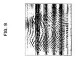
- FIG. 8is a view showing an example of a fingerprint image with a noise sampled in the fourth embodiment
- FIG. 9is a schematic longitudinal sectional view showing a construction of an identifying device (living-body detecting means) by biometrics information as the fifth embodiment of the present invention.
- FIG. 10is a flowchart for explaining a living-body determination procedure in the fifth embodiment
- FIG. 11is a block diagram showing a construction of an identifying device (living-body detecting means) by biometrics information as the sixth embodiment of the present invention.
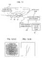
- FIGS. 12(A) and 12(B)are views showing examples of a fingerprint image and a blood vessel pattern sampled in the sixth embodiment, respectively;
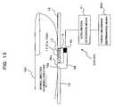
- FIG. 13is a schematic longitudinal sectional view showing a construction of an identifying device (living-body detecting means) by biometrics information as the seventh embodiment of the present invention
- FIG. 14is a schematic plan view showing a fingerprint sensor in an identifying device by biometrics information as the eighth embodiment of the present invention.
- FIG. 15is a flowchart for explaining an operation of the identifying device by biometrics information as the eighth embodiment of the present invention.
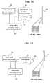
- FIG. 16is a block diagram showing a construction of an identifying device by biometrics information as the ninth embodiment of the present invention.
- FIG. 17is a block diagram showing a construction of a modification of the identifying device by biometrics information as the ninth embodiment of the present invention.
- FIG. 18is a view showing a concrete example of a plurality of strip-state partial images (fingerprint images) continuously sampled by the sweep type fingerprint sensor in the first to the eighth embodiments.
- FIGS. 1(A) to 1(C) and FIG. 2are views for explaining arrangement of a sensor in an identifying device by biometrics information according to a first to an eighth embodiments of the present invention, in which FIGS. 1(A) to 1(C) are plan views schematically showing arrangement states of a sensor (sensor surface) in the identifying device of each embodiment, and FIG. 2 is a view for explaining image sampling by a sweep type fingerprint sensor in each preferred embodiment.
- the identifying device in the first to the eighth embodimentsis to identify that a person to be identified is the person himself/herself using a fingerprint (biometrics information) of the person to be identified and comprises a sweep type fingerprint sensor 10 of a capacitance type or an electric-field detection type (weak electric-field type) as shown in FIGS. 1(A) to 1(C) and FIG. 2 .
- This sweep type fingerprint sensor (biometrics information input section) 10continuously samples an image of an outer skin surface of the person to be identified, moving in contact with a sampling surface (sensor surface, input surface) 11 . More specifically, this sensor continuously samples partial images of a fingerprint of a finger 100 (See FIG. 2 ), which is a living body portion of the person to be identified, while the finger 100 is relatively moved with respect to the sampling surface 11 , and inputs the partial images.
- the fingerprintis formed on an outer skin (finger 100 ) of the person to be identified and is a pattern consisting of ridge lines (contact portion) capable of contacting with the sampling surface 11 and valley lines (noncontact portion/gap portion) not in contact with the sampling surface 11 .
- the finger sensor 10samples a fingerprint image as a multivalued image using a difference in detection sensitivity between the ridge line portion in contact with the sampling surface 11 and the valley portion not in contact with the sampling surface 11 .
- the capacitance type sensorhas different brightness according to a distance from the sensor, and normally, the ridge line portion close to the sensor is displayed with a low brightness, while the valley line portion relatively far from the sensor is displayed with a high brightness.
- the sweep type fingerprint sensor 10is, as described above and shown in FIGS. 1(A) to 1(C) and FIG. 2 , sufficiently shorter than the length of the finger 100 and has the rectangular sampling surface (sensor surface/image pickup surface) 11 with a small area.
- the number of pixelsis 218 ⁇ 8 and the actual dimension is 16.1 mm ⁇ 6.5 mm ⁇ 0.8 mm (width ⁇ length ⁇ depth).
- the fingerprint sensor 10is used for sampling biometrics information for verification (fingerprint image for verification), which is used for comparison/verification with registered biometrics information (registered fingerprint image) at personal identification from the finger 100 of the person to be identified and inputs the sampled biometrics information for verification.
- FIG. 18a concrete example (an example of actually sampled plural partial fingerprint images) of the plural strip-state partial images continuously (in time-series manner) sampled by the sweep type fingerprint sensor 10 is shown in FIG. 18 .
- a living-body detecting means (living-body detecting sensor) 20( 20 A to 20 G) is provided for detecting if the finger 100 , for which the above fingerprint image for verification is being sampled/inputted by the fingerprint sensor 10 , is a living body or not (that is, if the finger to be sampled is a forged fingerprint or not).
- the sweep type fingerprint sensor 10or a fingerprint input device comprised by a one-dimensional line sensor or the like for sampling/inputting the above-mentioned strip-state partial images.
- the entire fingerprint imageis inputted by tracing the sensor surface 11 with the finger 100 . Therefore, the finger 100 passes both the far side of the fingerprint sensor 10 (upper side of FIGS. 1(A) to 1(C) and FIG. 2 ) and the front side (lower side of FIGS. 1(A) to 1(C) and FIG. 2 ) from the far side to the front side.
- living-body detection surfaces (sensor surfaces) 21 a , 21 b in the above living-body detecting means 20are arranged, as shown in FIGS. 1(A) to 1(C) , so that they are in contact with or in the proximity to the finger 100 being moved with respect to the fingerprint sensor 10 so as to input the fingerprint image for verification and also flush with or substantially flush with the sampling surface 11 of the fingerprint sensor 10 .
- the living-body detection surfaces 21 a , 21 b in the living-body detecting means 20forms a pair, and the sampling surface 11 of the fingerprint sensor 10 is arranged between the pair of the living-body detection surfaces 21 a , 21 b.
- the living-body detection surface 21 a in the living-body detecting means 20is arranged only on the side of a moving direction of the finger 100 (the above front side; lower side in this figure) with respect to the sensor surface 11 of the fingerprint sensor 10 .
- the living-body detection surface 21 b in the living-body detecting means 20is arranged only on the side opposite to the moving direction of the finger 100 (the above far side; upper side in this figure) with respect to the sensor surface 11 of the fingerprint sensor 10 .
- the finger 100since it is necessary that the finger 100 should be also placed at spots other than the sensor surface 11 of the sweep type fingerprint sensor 10 , different from the case of the planar fingerprint sensor, by arranging the living-body detection surface 21 a and/or 21 b of the living-body detecting means 20 (specifically, various living-body detecting means 20 A to 20 G, which will be described later referring to FIGS. 3 to 13 ) on one side or on both sides of the sensor surface of the fingerprint sensor 10 , as mentioned above, sure detection is made possible by the rectangular sampling surface (sensor surface) 11 of the sweep type fingerprint sensor 10 on whether the finger 100 , for which the fingerprint image is just being sampled, is a living body or not.
- the living-body detection surface 21 a and/or 21 b of the living-body detecting means 20specifically, various living-body detecting means 20 A to 20 G, which will be described later referring to FIGS. 3 to 13
- FIG. 3is a block diagram showing a construction of the identifying device (living-body detecting means) by biometrics information as the first embodiment of the present invention.
- the identifying device of the first embodiment shown in FIG. 3is provided with a living-body detecting means (living-body detecting sensor) 20 A comprised by a light emitting section 23 , a light receiving section 24 , a diffusion-light pattern determining means 25 and a forged fingerprint discriminating means 26 A.
- the light emitting section 23emits and irradiates light of a specific wavelength to the finger 100 , for which the fingerprint image is being sampled, and its light emitting surface is arranged in contact with the finger 100 being moved on the side of the finger moving direction (left side in this figure) of the sampling surface 11 as the living-body detection surface 21 a and flush with or substantially flush with the sampling surface 11 .
- the light receiving section 24receives diffusion light obtained when the light irradiated from the light emitting section 23 to the finger 100 is transmitted/diffused in the finger 100 , and its light receiving surface is arranged in contact with the finger 100 being moved on the side opposite to the finger moving direction (right side in this figure) of the sampling surface 11 as the living-body detection surface 21 b and flush with or substantially flush with the sampling surface 11 .
- the living-body detection surfaces 21 a , 21 b(the light emitting surface of the light emitting section 23 and the light receiving surface of the light receiving section 24 ) in the living-body detecting means 20 A form a pair, and the sampling surface 11 of the fingerprint sensor 10 is arranged between the pair of the living-body detection surfaces 21 a , 21 b.
- the diffusion-light pattern determining means 25determines a pattern of the diffusion light received by the light receiving section 24
- the forged fingerprint discriminating means 26 Adiscriminates a living body from a forged fingerprint based on the determination result by the diffusion-light pattern determining means 25 .
- the diffusion-light pattern determining means 25determines a pattern of intensity change of the diffusion light received by the light receiving section 24
- the forged fingerprint discriminating means 26 Adetermines that the finger 100 , for which the fingerprint image is being sampled, is a living body when the pattern determined by the diffusion-light pattern determining means 25 includes pulsation and that the finger 100 , for which the fingerprint image is being sampled, is a forged fingerprint when the pattern does not include the pulsation.
- a blood flow in the finger 100changes with heartbeat, and pulsation is generated in the intensity of the diffusion light with pulsation (pulsation according to heartbeat) accompanying the change in the blood flow.
- pulsationis not generated in a forged finger made by gummy substance or the like, for example.
- the living-body detecting means 20 A shown in FIG. 3can discriminate a living body from a forged fingerprint by the forged fingerprint discriminating means 26 A based on the result if the pattern of intensity change of the diffusion light includes pulsation or not.
- This first modificationis so constituted that a section for irradiating a spot light of a specific wavelength is provided as the light emitting section 23 , a section in a line sensor state is provided as the light receiving section 24 , the diffusion-light pattern determining means 25 determines a degree of diffusion of the diffusion light as a pattern of the diffusion light received by the light receiving section 24 , and the forged fingerprint discriminating means 26 A discriminates a living body from a forged fingerprint based on the diffusion degree determined by the diffusion-light pattern determining means 25 .
- the spot light irradiated from the light emitting section 23is not much diffused but transmitted through the forged finger as it is and received by the light receiving section 24 in the line sensor state. That is, the diffusion degree of the diffusion light is considerably small.
- the finger 100is a living body, the spot light irradiated from the light emitting section 23 is greatly diffused in the finger 100 and received by the light receiving section 24 in the line sensor state. That is, the diffusion degree of the diffusion light is considerably large.
- the forged fingerprint discriminating means 26 Adiscrimination between a living body and a forged fingerprint based on the diffusion degree of the diffusion light is made possible by the forged fingerprint discriminating means 26 A. At this time, if the light receiving range of the diffusion light is wide in the light receiving section 24 in the line sensor state, the diffusion degree is determined as large, while if the light receiving range of the diffusion light is narrow, the diffusion degree is determined as small.
- a second modification of the living-body detecting means 20 A of the first embodimentwill be described.
- This second modificationis so constituted that a section for irradiating light of a specific wavelength group (a wavelength group absorbed in blood, for example; specifically, red light, near-infrared light in LED) is provided as the light emitting section 23 , the diffusion-light pattern determining means 25 determines a wavelength of the diffusion light as a pattern of the diffusion light received by the light receiving section 24 , and the forged fingerprint discriminating means 26 A discriminates a living body from a forged fingerprint based on the wavelength determined by the diffusion-light pattern determining means 25 .
- a specific wavelength groupa wavelength group absorbed in blood, for example; specifically, red light, near-infrared light in LED
- the pair of living-body detection surfaces 21 a , 21 bare arranged so that the sampling surface 11 of the fingerprint sensor 10 is arranged between them, but both the light emitting surface of the light emitting section 23 and the light receiving surface of the light receiving section 24 may be arranged as the living-body detection surface 21 a on the side of the finger moving direction (left side in the figure) of the sampling surface 11 as in the arrangement state shown in FIG. 1(B) , or they may be arranged as the living-body detection surface 21 b on the side opposite to the finger moving direction (right side in the figure) of the sampling surface 11 as in the arrangement state shown in FIG. 1(C) .
- FIG. 4is a block diagram showing a construction of the identifying device (living-body detecting means) by biometrics information as the second embodiment of the present invention.
- the identifying device of the second embodiment shown in FIG. 4is provided with a living-body detecting means (living-body detecting sensor) 20 B comprised by the light emitting section 23 , the light receiving section 24 , a color pattern determining means 27 and a forged fingerprint discriminating means 26 B.
- the light emitting section 23emits and irradiates white light to the finger 100 , for which the fingerprint image is being sampled, and its light emitting surface is arranged in contact with the finger 100 being moved on the side of the finger moving direction (left side in this figure) of the sampling surface 11 as the living-body detection surface 21 a and flush with or substantially flush with the sampling surface 11 .
- the light receiving section 24receives light obtained when the light irradiated from the light emitting section 23 to the finger 100 is transmitted/diffused in the finger 100 , and its light receiving surface is arranged in contact with the finger 100 being moved on the side opposite to the finger moving direction (right side in this figure) of the sampling surface 11 as the living-body detection surface 21 b and flush with or substantially flush with the sampling surface 11 .
- the living-body detection surfaces 21 a , 21 b(the light emitting surface of the light emitting section 23 and the light receiving surface of the light receiving section 24 ) in the living-body detecting means 20 B form a pair, and the sampling surface 11 of the fingerprint sensor 10 is arranged between the pair of the living-body detection surfaces 21 a , 21 b.
- the color pattern determining means 27detects/determines a color pattern of the light received by the light receiving section 24 , and the forged fingerprint discriminating means 26 B discriminates a living body from a forged fingerprint based on the determination result by the color pattern determining means 27 . More specifically, the forged fingerprint discriminating means 26 B determines that the finger 100 , for which the fingerprint image is being sampled, is a living body when the color pattern determined by the color pattern determining means 27 is white (when it changes from red (pink) to white) and that the finger 100 , for which the fingerprint image is being sampled, is a forged fingerprint when the color pattern is not white (when the above change does not occur).
- the living-body detecting means 20 B shown in FIG. 4can discriminate a living body from a forged fingerprint based on the result whether the color detected/determined by the color pattern determining means 27 is white or not (or, whether there was a change from red (pink) to white), using the forged fingerprint discriminating means 26 B.
- FIG. 5is a block diagram showing a construction of a modification of an identifying device (living-body detecting means) by biometrics information as the second embodiment of the present invention.
- the pair of living-body detection surfaces 21 a , 21 bare arranged with the sampling surface 11 of the fingerprint sensor 10 between them.
- both the light emitting surface of the light emitting section 23 and the light receiving surface of the light receiving section 24are arranged as the living-body detection surface 21 b on the side (right side in the figure) opposite to the finger moving direction of the sampling surface 11 as in the arrangement state shown in FIG. 1(C) .
- the construction of the identifying device shown in FIG. 5 (the living-body detecting means 20 B) other than this arrangement state of light emitting surface of the light emitting section 23 and the light receiving surface of the light receiving section 24is the same as the construction shown in FIG. 4 .
- the light emitting surface of the light emitting section 23is arranged between the sampling surface 11 of the fingerprint sensor 10 and the light receiving surface of the light receiving section 24 .
- both the light emitting surface of the light emitting section 23 and the light receiving surface of the light receiving section 24may also be arranged as the living-body detection surface 21 a on the side (left side in the figure) of the finger moving direction of the sampling surface 11 in this second embodiment, though not shown, as in the arrangement state shown in FIG. 1(B) .
- FIG. 6is a block diagram showing a construction of the identifying device (living-body detecting means) by biometrics information as the third embodiment of the present invention.
- the identifying device of the third embodiment shown in FIG. 6is provided with a living-body detecting means (living-body detecting sensor) 20 C comprised by a pair of electrodes 28 a , 28 b , a resistance value determining means 29 and a forged fingerprint discriminating means 26 C.
- the pair of electrodes 28 a , 28 breceives an electric power of a predetermined voltage from a power source, not shown, and flows an electric current through the finger 100 , for which the fingerprint image is being sampled, from the electrode 28 a to the electrode 28 b .
- Exposed surfaces of the electrodes 28 a , 28 bare arranged as the living-body detection surface 21 b to be in contact with the finger 100 being moved on the side (right side in the figure) opposite to the finger moving direction of the sampling surface 11 and flush with or substantially flush with the sampling surface 11 as in the arrangement state shown in FIG. 1(C) .
- the exposed surface of the electrode 28 ais arranged between the sampling surface 11 of the fingerprint sensor 10 and the exposed surface of the electrode 28 b.
- the resistance value determining means 29detects/determines an electric resistance value between the electrodes 28 a , 28 b (that is, the electric resistance value of the finger 100 , for which the fingerprint image is being sampled) by detecting an electric current flowing from the electrode 28 a to the electrode 28 b , and the forged fingerprint discriminating 26 C discriminates a living body from a forged fingerprint based on the electric resistance value detected/determined by the resistance value determining means 29 .
- the living body and the forged finger made of gummy substance, gelatin or the likeare naturally different from each other in electric resistance values, by measuring/storing an electric resistance value (range of electric resistance value) of a living body in advance, discrimination between the living body and the forged fingerprint can be made by the forged fingerprint discriminating means 26 C based on the result on whether the electric resistance value detected by the resistance value determining means 29 falls within a predetermined range or not.
- the finger 100for which the fingerprint image is being sampled, is determined as a living body, while if the value does not fall within the range, the finger 100 , for which the fingerprint image is being sampled, is determined as a forged finger.
- exposed surfaces of the pair of the electrodes 28 a , 28 bare arranged as the living-body detection surface 21 b on the side (right side in the figure) opposite to the finger moving direction of the sampling surface 11 , but they may be arranged as the respective living-body detection surfaces 21 a , 21 b with the sampling surface 11 of the fingerprint sensor 10 between them as in the arrangement state shown in FIG. 1(A) , or they may be arranged as the living-body detection surface 21 a on the side (left side in the figure) of the finger moving direction of the sampling surface 11 as in the arrangement state shown in FIG. 1(B) .
- FIG. 7is a block diagram showing a construction of the identifying device (living-body detecting means) by biometrics information as the fourth embodiment of the present invention
- FIG. 8is a view showing an example of the fingerprint image with noise sampled in the fourth embodiment.
- the identifying device in the fourth embodiment shown in FIG. 7is provided with a living-body detecting means (living-body detecting sensor) 20 D comprised by an electrode 30 , a pulse signal generating means 31 , an image noise detecting means 32 and a forged fingerprint discriminating means 26 D.
- This living-body detecting means 20 Dapplies an electric noise of a specific pattern to the finger 100 and discriminates a living body from a forged fingerprint based on appearance situation of a noise on the fingerprint image sampled by the fingerprint sensor 10 .
- the sweep type fingerprint sensor 10is a capacitance type or an electric-field detection type (weak electric-field type), and the electrode 30 applies a pulse signal (electric signal) generated by the pulse signal generating means 31 as an electric noise of a specific pattern to the finger 100 , for which the fingerprint image is being sampled.
- the exposed surface of the electrode 30is also arranged as the living-body detection surface 21 b in contact with the finger 100 being moved on the side (right side in the figure) opposite to the finger moving direction of the sampling surface 11 and flush with or substantially flush with the sampling surface 11 as in the arrangement state shown in FIG. 1(C) .
- the image noise detecting means 32detects the image noise (noise appearance situation on the fingerprint image sampled by the fingerprint sensor 10 ) according to the above electric noise (pulse signal) from a plurality of partial fingerprint images continuously sampled by the fingerprint sensor 10 , and the forged fingerprint discriminating means 26 D discriminates a living body from a forged fingerprint based on the image noise (noise appearance situation) detected by the image noise detecting means 32 .
- the living-body detecting means 20 D shown in FIG. 7can discriminate a living body from a forged fingerprint by determining by the forged fingerprint discriminating means 26 D if the image noise (noise appearance situation) detected by the image noise detecting means 32 corresponds to an electric noise of the specific pattern applied to the finger 100 by the electrode 30 and the pulse signal generating means 31 . That is, if the image noise (noise appearance situation) detected by the image noise detecting means 32 corresponds to the electric noise of the above specific pattern, the finger 100 , for which the fingerprint image is being sampled, is determined as a living body, while if not, the finger 100 , for which the fingerprint image is being sampled, is determined as a forged finger.
- the exposed surface of the electrode 30is arranged as the living-body detection surface 21 b on the side (right side in the figure) opposite to the finger moving direction of the sampling surface 11 , but this exposed surface of the electrode 30 may be arranged as the living-body detection surface 21 a on the side (left side in the figure) of the finger moving direction of the sampling surface 11 as in the arrangement state shown in FIG. 1(B) .
- the living-body detecting means 20 Dis applied to the fingerprint sensor 10 of the sweep type, but it may be a usual planar fingerprint sensor of the capacitance type or the electric-field detection type (weak electric-field type) to which the living-body detecting means 20 D is applied as above so that the finger 100 , for which the fingerprint image is being sampled from the image noise, is a living body or a forged finger can be discriminated.
- FIG. 9is a schematic longitudinal sectional view showing a construction of the identifying device (living-body detecting means) by biometrics information as the fifth embodiment of the present invention
- FIG. 10is a flowchart (Steps S 1 to S 5 ) for explaining a living-body determination procedure in the fifth embodiment.
- the identifying device of the fifth embodiment shown in FIG. 9is provided with a living-body detecting means (living-body detecting sensor) 20 E comprised by a pressure sensor 33 , a pressure determining means 34 and a forged fingerprint discriminating means 26 E.
- This living-body detecting means 20 Edetects a pressing force of the finger 100 , for which the fingerprint image is being sampled, and discriminates a living body from a forged fingerprint based on the detected pressing force.
- the pressure sensor 33detects the pressing force of the finger 100 , for which the fingerprint image is being sampled, on the sampling surface 11 , and the exposed surface (contact surface with the finger 100 ) of this pressure sensor 33 is also arranged as the living-body detection surface 21 b in contact with the finger 100 being moved on the side (left side in the figure) of the finger moving direction of the sampling surface 11 and flush with or substantially flush with the sampling surface 11 as in the arrangement state shown in FIG. 1(B) .
- the pressure determining means 34determines if the pressing force detected by the pressure sensor 33 is equal to or larger than a predetermined pressure (threshold value) or not, and the forged fingerprint discriminating means 26 E discriminates a living body from a forged fingerprint based on the determination result by the pressure determining means 34 .
- a forged fingerprintis to be read by the fingerprint sensor 10 using a forged finger made of gummy substance, gelatin or the like, for example, it is necessary to press the forged finger on the sampling surface 11 of the fingerprint sensor 10 with a pressing force larger than the case where the fingerprint of a living finger is to be read by the fingerprint sensor 10 .
- the living-body detecting means 20 E shown in FIG. 9during sampling of a fingerprint image of the finger 100 by the fingerprint sensor 10 (Step S 1 in FIG. 10 ), detects a pressing force of the finger 100 on the fingerprint sensor 10 by the pressure sensor 33 (Step S 2 in FIG. 10 ), and determines if the detected pressing force is equal to or larger than a threshold value by the pressure determining means 34 (Step S 3 in FIG. 10 ). Then, if the detected pressing force is equal to or larger than the threshold value (YES route of Step S 3 ), the forged fingerprint discriminating means 26 E determines that the finger 100 is a forged finger (Step S 4 in FIG.
- the forged fingerprint discriminating means 26 Edetermines that the finger 100 is a living body (Step S 5 in FIG. 10 ). In this way, discrimination between a living body and a forged fingerprint is also made possible by the living-body detecting means 20 E shown in FIG. 9 .
- the exposed surface of the pressure sensor 33is arranged as the living-body detection surface 21 b on the side (right side in the figure) opposite to the finger moving direction of the sampling surface 11 , but this exposed surface of the pressure sensor 33 may be arranged as the living-body detection surface 21 a on the side (right side in the figure) opposite to the finger moving direction of the sampling surface 11 as in the arrangement state shown in FIG. 1(C) .
- the pressure sensor 33may be arranged at a lower part (lower direction in FIG. 9 ) of the fingerprint sensor 10 in contact with this fingerprint sensor 10 so as to detect the pressing force of the finger 100 through the sampling surface 11 and the fingerprint sensor 10 .
- the sampling surface 11 itself of the fingerprint sensor 10functions as the living-body detection surface 21 a / 21 b.
- time series change of the pressing force of the finger of a person to be identifiedis detected/registered as a habit of the person to be identified at sampling of the registered fingerprint image of the person to be identified, and the time series change of the pressing force of the finger is detected by the pressure sensor 33 at sampling of a fingerprint image for verification from the person to be identified at personal identification.
- the detected time series change and the time series change registered in advanceare compared by the pressure determining means 34 , and if the difference exceeds a predetermined range, the finger 100 is determined as a forged finger by the forged fingerprint discriminating means 26 E, while if the difference is within the above predetermined range, the finger is determined as a living body (hence, the identity of the person to be identified is confirmed) by the forged fingerprint discriminating means 26 E. That is, the time-series change of the pressing force can be used as an auxiliary determining means for identity verification (personal identification), which can further improve reliability of personal identification.
- FIG. 11is a block diagram showing a construction of the identifying device (living-body detecting means) by biometrics information as the sixth embodiment of the present invention
- FIGS. 12(A) and 12(B)are views showing examples of a fingerprint image and a blood vessel pattern sampled in the sixth embodiment, respectively.
- the identifying device of the sixth embodiment shown in FIG. 11is provided with a living-body detecting means (living-body detecting sensor) 20 F comprised by a near-infrared light emitting section 35 , a line sensor 36 , a blood-vessel pattern detecting means 37 and a forged fingerprint discriminating means 26 F, and a blood-vessel pattern verifying means 38 is also provided.
- a living-body detecting meansliving-body detecting sensor 20 F comprised by a near-infrared light emitting section 35 , a line sensor 36 , a blood-vessel pattern detecting means 37 and a forged fingerprint discriminating means 26 F, and a blood-vessel pattern verifying means 38 is also provided.
- the living-body detecting means (living-body detecting sensor) 20 Fsamples a blood vessel pattern in the finger 100 by irradiating light (near-infrared light) to the finger 100 , for which the fingerprint image is being sampled, and discriminates a living body from a forged fingerprint based on the sampled blood vessel pattern.
- the near-infrared light emitting section 35irradiates near-infrared light to the finger 100 , for which the fingerprint image is being sampled, and the light emitting surface is arranged as the living-body detection surface 21 b in contact with the finger 100 being moved on the side (right side in the figure) opposite to the finger moving direction of the sampling surface 11 and flush with or substantially flush with the sampling surface 11 as in the arrangement state shown in FIG. 1(C) .
- the line sensor 36receives light obtained when the near-infrared light irradiated from the near-infrared light emitting section 35 to the finger 100 is transmitted through the finger 100 , and the light receiving surface is arranged as the living-body detection surface 21 b in contact with the finger 100 being moved on the side (right side in the figure) opposite to the finger moving direction of the sampling surface 11 and flush with or substantially flush with the sampling surface 11 as in the arrangement state shown in FIG. 1(C) .
- the light emitting surface of the near-infrared light emitting section 35is arranged between the sampling surface 11 of the fingerprint sensor 10 and the light receiving surface of the line sensor 36 .
- the blood-vessel pattern detecting means 37detects a blood vessel (vein) pattern in the finger 100 by reconfiguring the blood vessel (vein) pattern in the finger 100 from one-dimensional information (partial image information of the blood vessel pattern) received/detected by the line sensor 36 using the fingerprint image sampled by the fingerprint sensor 10 and reconfigured (See FIG. 12(A) , for example) as encoder information. Also, the forged fingerprint discriminating means 26 F discriminates a living body from a forged fingerprint based on the detection result by the blood-vessel pattern detecting means 37 .
- a forged finger made of gummy substance, gelatin or the likedoes not have a blood vessel (vein) therein as a matter of fact, and an image obtained by reconfiguring the one-dimensional information received/detected by the line sensor 36 as mentioned above does not have a blood vessel pattern.
- the image obtained by reconfiguring the one-dimensional information received/detected by the line sensor 36 as mentioned abovehas a blood vessel pattern.
- the forged fingerprint discriminating means 26 Fcan discriminate between a living body and a forged fingerprint based on presence/absence of a blood vessel pattern in an image reconfigured by the blood-vessel pattern detecting means 37 . That is, if the blood vessel pattern exists in the image reconfigured by the blood-vessel pattern detecting means 37 , the finger 100 , for which the fingerprint image is being sampled, is determined as a living body, while if not, the finger 100 , for which the fingerprint image is being sampled, is determined as a forged finger.
- the blood-vessel pattern verifying means 38performs personal identification based on the blood vessel pattern detected by the blood-vessel pattern detecting means 37 in addition to the personal identification based on the fingerprint image sampled by the fingerprint sensor 10 . That is, the blood vessel pattern of a finger of the person to be identified is sampled/registered at sampling of the registered fingerprint image of the person to be identified, and the blood vessel pattern of the finger 100 is sampled as above by the near-infrared light emitting section 35 , the line sensor 36 and the blood-vessel pattern detecting means 37 at the same time when the fingerprint image for verification is sampled from the person to be identified at personal identification. Then the sampled blood vessel pattern and the blood vessel pattern registered in advance are verified similar to the case of fingerprint verification. By this, not only personal identification by fingerprint but also personal identification by blood vessel pattern is performed, which can further improve reliability of personal identification.
- the pair of the light emitting surface of the near-infrared light emitting section 35 and the light receiving surface of the line sensor 36are arranged as the living-body detection surface 21 b on the side (right side in the figure) opposite to the finger moving direction of the sampling surface 11 , but the light emitting surface and light receiving surface may be arranged as the living-body detection surfaces 21 a , 21 b , respectively, so that the sampling surface 11 of the fingerprint sensor 10 are arranged between them as in the arrangement state shown in FIG. 1(A) , or they may be arranged as the living-body detection surface 21 a on the side (left side in the figure) of the finger moving direction of the sampling surface 11 as in the arrangement state shown in FIG. 1(B) .
- the one-dimensional information received/detected by the line sensor 36is reconfigured using the fingerprint image sampled and reconfigured by the fingerprint sensor 10 as encoder information, but on the contrary, after the blood vessel pattern image as shown in FIG. 12(B) , for example, is reconfigured from the one-dimensional information received/detected by the line sensor 36 , the fingerprint image as shown in FIG. 12(A) , for example, may be reconfigured from the partial fingerprint image sampled by the fingerprint sensor 10 using the blood vessel pattern image as encoder information.
- FIG. 13is a schematic longitudinal sectional view showing the construction of the identifying device (living-body detecting means) by biometrics information as the seventh embodiment of the present invention.
- the identifying device of the seventh embodiment shown in FIG. 13is provided with a living-body detecting means (living-body detecting sensor) 20 G comprised by a rubber platform 39 , an acceleration sensor 40 , an acceleration determining means 41 and a forged fingerprint discriminating means 26 G.
- This living-body detecting means 20 Gdetects an acceleration of the finger 100 , for which the fingerprint image is being sampled, and discriminates a living body from a forged fingerprint based on the detected change of acceleration.
- the acceleration sensor 40is mounted on a board 12 of the fingerprint sensor 10 , and this fingerprint sensor 10 with the acceleration sensor 40 (board 12 ) is mounted to the rubber platform 39 in the L-shape. Additionally, an upper end 39 a of the L-shaped rubber platform 39 and the sampling surface 11 of the fingerprint sensor 10 are exposed to the outside through an opening portion 13 a of an enclosure 13 of this device. At this time, the sampling surface 11 of the fingerprint sensor 10 is flush with an upper face of the enclosure 13 or projects slightly upward from the upper face of the enclosure 13 . At this time, in the seventh embodiment, the sampling surface 11 of the fingerprint sensor 10 itself functions as the living-body detection surface 21 a / 21 b.
- the board 12 of the fingerprint sensor 10is displaced in the horizontal direction (moving direction of the finger 100 ) by a slight amount while elastically deforming the rubber platform 39 by friction between the finger 100 and the sampling surface 11 of the fingerprint sensor 10 .
- the acceleration sensor 40detects the acceleration in a time series when the above displacement is generated.
- a habit at sweeping of the finger of the person to be identifiedis detected/registered as time-series change of acceleration at sampling of a registered fingerprint image of the person to be identified.
- the acceleration determining means 41compares time-series change of the acceleration of the finger 100 detected by the acceleration sensor 40 and the time-series change of the acceleration registered in advance for the person to be identified, and the forged fingerprint discriminating means 26 G discriminates a living body from a forged fingerprint based on the comparison result by the acceleration determining means 41 .
- time-series change of acceleration of the finger 100is detected by the acceleration sensor 40 at the same time. Then the detected time-series change and the time-series change registered in advance are compared by the acceleration determining means 41 , and if the difference exceeds a predetermined range, the finger 100 is determined as a forged finger by the forged finger discriminating means 26 G, while if the difference is within the above predetermined range, the finger 100 is determined as a living body (hence, that the identity of the person to be identified is confirmed) by the forged finger discriminating means 26 G.
- time-series change of accelerationcan be also used as an auxiliary determining means for identity verification (personal identification), which can further improve reliability of personal identification.
- a forged fingerprint made by gummy substance, gelatin or the likehas a different surface friction and the acceleration is largely different.
- FIG. 14is a schematic plan view showing a fingerprint sensor in the identifying device by biometrics information as the eighth embodiment of the present invention
- FIG. 15is a flowchart for explaining operation of the identifying device by biometrics information as the eighth embodiment of the present invention.
- a sweep type fingerprint sensor (biometrics information input section) 10 A in the identifying device shown in FIG. 14basically has the same structure as that of the sweep type fingerprint sensor 10 in the above first to the seventh embodiments and samples a fingerprint image from a finger of a person to be identified similarly to the fingerprint sensor 10 , but the sweep type fingerprint sensor 10 A of the eighth embodiment is different from the sweep type fingerprint sensor 10 in the first to the seventh embodiments in the widths of the sampling surfaces 11 a , 11 (longitudinal length).
- the sampling surface 11 of the sweep type fingerprint sensor 10 of the first to the seventh embodimentshas a width (approximately 16.1 mm as mentioned above) capable of sampling the fingerprint image from the single finger 100 of the person to be identified
- the sampling surface 11 a of the sweep type fingerprint sensor 10 A of the eighth embodimenthas a width (35 mm or more, for example) capable of sampling/inputting a fingerprint image of a plurality of fingers (2 fingers, a right-hand forefinger 100 a and a right-hand middle finger 100 b in the eighth embodiment) as a living body portion as biometrics information for verification at the same time.
- a position relation between the plurality of fingers (the forefinger and the middle finger, for example) of the person to be identifiedis detected/registered at sampling of a registered fingerprint image of the person to be identified.
- Step S 11Operation of the identifying device of eighth embodiment that the fingerprint images of the plurality of fingers ( 100 a , 100 b ) are sampled at the same time in this way will be described according to the flowchart (Steps S 11 to S 19 ) shown in FIG. 15 .
- the two fingers 100 a , 100 bare swept at the same time by the fingerprint sensor 10 A (Step S 11 ), a first finger (the forefinger 100 a , for example) is verified (Step S 12 ), and a verification matching rate is determined for the first finger (Step S 13 ).
- Step S 19If the verification matching rate is less than a predetermined threshold value (NO route of Step S 13 ), it is determined as verification failure (Step S 19 ), while if it is equal to or larger than the predetermined threshold value (YES route of Step S 13 ), a second finger (the middle finger 100 b , for example) is verified (Step S 14 ).
- the verification matching rate for the second fingeris determined (Step S 15 ), and if the verification matching rate is less than a predetermined threshold value (NO route of Step S 15 ), it is determined as verification failure (Step S 19 ), while if the rate is equal to or larger than the predetermined threshold value (YES route of Step S 15 ), the position relation between the first finger and the second finger sampled at personal identification is compared with that registered in advance for the person to be identified (Step S 16 ).
- Step S 17a difference between the two position relations is determined (Step S 17 ) and if the difference is equal to or larger than a predetermined threshold value (NO route of Step S 17 ), it is determined as verification failure (Step S 19 ), while if the difference is less than the predetermined threshold value (YES of Step S 17 ), it is determined/confirmed that the person to be identified is the registered person himself/herself (Step S 18 ).
- the identifying devicethat can sample the fingerprint images of the plural fingers ( 100 a , 100 b ) at the same time as mentioned above, the following operational advantages can be obtained.
- input of forged fingerprintscan be suppressed by registering the relation of input positions of at least two fingerprint images.
- the position relation of fingerprint information of the forefinger 100 a and the middle finger 100 bcan be also used as information to identify the person. That is, there is an effect that difficulty of forgery is increased than a single fingerprint.
- the living-body detection surfaces 21 a , 21 of the living-body detecting means 20are also arranged as in the first to the seventh embodiments, and the same operational advantages as in the above-mentioned first to the seventh embodiments can be obtained, but even without the living-body detecting means 20 ( 20 A to 20 G), the above operational advantages specific to the identifying device of the eighth embodiment can be obtained.
- FIG. 16is a block diagram showing a construction of the identifying device by biometrics information as the ninth embodiment of the invention
- FIG. 17is a block diagram showing a modification of the identifying device by biometrics information as the ninth embodiment of the invention.
- the identifying device in the ninth embodimenthas a construction different from the basic construction of the first to the eighth embodiments described referring to FIGS. 1(A) to 1(C) .
- the identifying device shown in FIG. 16comprises a face image camera 50 , a magnifying camera 51 , a face image identifying means 60 and a regularity detecting means 70 .
- the face image camera (living-body information input section) 50picks up/inputs the face of a person to be identified (living body portion) so as to sample face image information for verification (biometrics information for verification) from the face of the person to be identified to be compared/verified with the registered face image information (registered biometrics information) at personal identification.
- the face image identifying means 60performs personal identification by comparing/verifying the face image information sampled by the face image camera 50 with the registered face image information registered in advance for the person to be identified.
- the magnifying camera 51 , the face image identifying means 60 and the regularity detecting means 70function as the living-body detecting means for detecting if the face, for which face image information for verification is being sampled/inputted by the face camera 50 , is a living body or not.
- the living-body detecting means in this ninth embodimentobtains a close-up image of the face of the person to be identified, and when a regular color pixel array is detected from the obtained close-up image, the living-body detecting means determines that the face image information sampled by the face image camera 50 is inputted by a forged article, not a living body.
- the magnifying camera 51captures/obtains a close-up image (enlarged image) of the face of the person to be identified being captured by the face image camera 50 and it is attached to the face image camera 50 .
- the regularity detecting means 70detects presence/absence of a regular color pixel array from the close-up image (enlarged image) obtained by the magnifying camera 51 .
- component colors of the regular color pixel arrayinclude, for example, a combination of red (R), green (G) and blue (B), a combination of yellow (Y), magenta (M), cyan (C) and black (K), or a combination of yellow (Y), magenta (M), cyan (C).
- the combination of red (R), green (G) and blue (B)is detected when a forged face image displayed on a high-definition liquid crystal panel 80 is presented to the cameras 50 , 51 as shown in FIG. 16 , for example.
- the combination of yellow (Y), magenta (M), cyan (C) and black (K) or the combination of yellow (Y), magenta (M) and cyan (C)is detected when a face image printed matter on which a high-definition image is printed out is presented to the cameras 50 , 51 .
- the face image identifying means 60determines that the face being captured is not a living body, that is, a forged article (liquid crystal screen or high-definition printed matter) when presence of the above-mentioned regular color pixel array is detected by the regularity detecting means 70 , while if the presence of the regular color pixel array is not detected, the face being captured is determined as a living body.
- the identifying device of the ninth embodimentwhen the face image by the high-definition liquid crystal panel 80 is inputted through the cameras 50 , 51 , regular RGB pixel arrays are detected from enlarged images by the camera 51 and the regularity detecting means 70 , and when a face image of a printed matter on which a high-definition image is printed out, for example, is inputted through the cameras 50 , 51 , regular pixel arrays of YMCK or YMC are detected from enlarged images by the camera 51 and the regularity detecting means 70 .
- a living body and a forged articlecan be surely discriminated by surely detecting whether or not a face being captured by the cameras 50 , 51 is a forged article such as a display (liquid crystal panel 80 ) or a printed matter, and input/personal identification by a forged article (face, which is not a living body) can be surely precluded.
- the identifying device of the ninth embodimentcan also surely preclude illegal use by impersonation using a forged article and realize more reliable personal identification.
- a magnifying lens 52(zoom function) is provided at the face image camera 50 , and the identifying device shown in FIG. 17 obtains the same close-up image (enlarged image) as above by the magnifying lens 52 (zoom function) of the face image camera 50 . Only this point is a difference between the identifying device shown in FIG. 16 and the device shown in FIG. 17 , and the identifying device shown in FIG. 17 can also obtain the same operational advantage as that of the identifying device shown in FIG. 16 .
- the present inventionis not limited to this but may be applied to the case where an image of an iris, blood vessel pattern, auricle, fingerprint, palm print or hand print is sampled/inputted in the noncontact manner using a camera or the like and used as biometrics information, and the same operational advantage as that of the above ninth embodiment can be obtained.
- the living-body detection surface of the living-body detecting meansis arranged in contact with or in the proximity to a living body portion being moved with respect to the biometrics information input section, whether the living body portion, for which biometrics information is being sampled, is a living body or not can be surely detected, illegal use by impersonation using a forged fingerprint or the like is surely precluded and more reliable personal identification can be realized.
- the present inventionis suitable to be used for an identification system which performs a personal identification using biometrics information such as an iris, face, blood vessel pattern, auricle, fingerprint, palm print, hand print or the like, for example, and its usability is considered to be extremely high.
Landscapes
- Engineering & Computer Science (AREA)
- Human Computer Interaction (AREA)
- Physics & Mathematics (AREA)
- General Physics & Mathematics (AREA)
- Multimedia (AREA)
- Theoretical Computer Science (AREA)
- Measurement Of The Respiration, Hearing Ability, Form, And Blood Characteristics Of Living Organisms (AREA)
- Image Input (AREA)
Abstract
Description
Claims (4)
Applications Claiming Priority (1)
| Application Number | Priority Date | Filing Date | Title |
|---|---|---|---|
| PCT/JP2004/000153WO2005069212A1 (en) | 2004-01-13 | 2004-01-13 | Authenticator using organism information |
Related Parent Applications (1)
| Application Number | Title | Priority Date | Filing Date |
|---|---|---|---|
| PCT/JP2004/000153ContinuationWO2005069212A1 (en) | 2004-01-13 | 2004-01-13 | Authenticator using organism information |
Publications (2)
| Publication Number | Publication Date |
|---|---|
| US20090232367A1 US20090232367A1 (en) | 2009-09-17 |
| US7689013B2true US7689013B2 (en) | 2010-03-30 |
Family
ID=34792044
Family Applications (1)
| Application Number | Title | Priority Date | Filing Date |
|---|---|---|---|
| US11/483,874Expired - Fee RelatedUS7689013B2 (en) | 2004-01-13 | 2006-07-11 | Identifying device by biometrics information |
Country Status (4)
| Country | Link |
|---|---|
| US (1) | US7689013B2 (en) |
| EP (1) | EP1708135B1 (en) |
| JP (1) | JP4468896B2 (en) |
| WO (1) | WO2005069212A1 (en) |
Cited By (56)
| Publication number | Priority date | Publication date | Assignee | Title |
|---|---|---|---|---|
| US20080123905A1 (en)* | 2006-06-26 | 2008-05-29 | Kazutaka Ito | Biometrics device |
| US20080130969A1 (en)* | 2006-11-02 | 2008-06-05 | Tomoyuki Asano | Imaging Apparatus |
| US20080219521A1 (en)* | 2004-04-16 | 2008-09-11 | Validity Sensors, Inc. | Method and Algorithm for Accurate Finger Motion Tracking |
| US20080226132A1 (en)* | 2004-04-16 | 2008-09-18 | Validity Sensors, Inc. | Unitized Ergonomic Two-Dimensional Fingerprint Motion Tracking Device and Method |
| US20080240523A1 (en)* | 2004-04-16 | 2008-10-02 | Validity Sensors, Inc. | Method and Apparatus for Two-Dimensional Finger Motion Tracking and Control |
| US20080279373A1 (en)* | 2007-05-11 | 2008-11-13 | Validity Sensors, Inc. | Method and System for Electronically Securing an Electronic Device Using Physically Unclonable Functions |
| US20090083850A1 (en)* | 2007-09-24 | 2009-03-26 | Apple Inc. | Embedded authentication systems in an electronic device |
| US20090154779A1 (en)* | 2007-12-14 | 2009-06-18 | Validity Sensors, Inc. | System and method to remove artifacts from fingerprint sensor scans |
| US20090153297A1 (en)* | 2007-12-14 | 2009-06-18 | Validity Sensors, Inc. | Smart Card System With Ergonomic Fingerprint Sensor And Method of Using |
| US20100026451A1 (en)* | 2008-07-22 | 2010-02-04 | Validity Sensors, Inc. | System, device and method for securing a device component |
| US20100119124A1 (en)* | 2008-11-10 | 2010-05-13 | Validity Sensors, Inc. | System and Method for Improved Scanning of Fingerprint Edges |
| US20100180136A1 (en)* | 2009-01-15 | 2010-07-15 | Validity Sensors, Inc. | Ultra Low Power Wake-On-Event Mode For Biometric Systems |
| US20100177940A1 (en)* | 2009-01-15 | 2010-07-15 | Validity Sensors, Inc. | Apparatus and Method for Culling Substantially Redundant Data in Fingerprint Sensing Circuits |
| US20100176823A1 (en)* | 2009-01-15 | 2010-07-15 | Validity Sensors, Inc. | Apparatus and Method for Detecting Finger Activity on a Fingerprint Sensor |
| US20100176892A1 (en)* | 2009-01-15 | 2010-07-15 | Validity Sensors, Inc. | Ultra Low Power Oscillator |
| US20100182126A1 (en)* | 2008-12-18 | 2010-07-22 | Martis Dinesh J | Biometric sensing apparatus and methods incorporating the same |
| US20100208953A1 (en)* | 2009-02-17 | 2010-08-19 | Validity Sensors, Inc. | Illuminated Fingerprint Sensor and Method |
| US20100284565A1 (en)* | 2006-09-11 | 2010-11-11 | Validity Sensors, Inc. | Method and apparatus for fingerprint motion tracking using an in-line array |
| US20110002461A1 (en)* | 2007-05-11 | 2011-01-06 | Validity Sensors, Inc. | Method and System for Electronically Securing an Electronic Biometric Device Using Physically Unclonable Functions |
| US20110102567A1 (en)* | 2009-10-30 | 2011-05-05 | Validity Sensors, Inc. | Integrated Fingerprint Sensor and Display |
| US20110175703A1 (en)* | 2010-01-15 | 2011-07-21 | Benkley Iii Fred G | Electronic Imager Using an Impedance Sensor Grid Array Mounted on or about a Switch and Method of Making |
| US8331096B2 (en) | 2010-08-20 | 2012-12-11 | Validity Sensors, Inc. | Fingerprint acquisition expansion card apparatus |
| US8374407B2 (en) | 2009-01-28 | 2013-02-12 | Validity Sensors, Inc. | Live finger detection |
| US8421890B2 (en) | 2010-01-15 | 2013-04-16 | Picofield Technologies, Inc. | Electronic imager using an impedance sensor grid array and method of making |
| US8520913B2 (en) | 2008-04-04 | 2013-08-27 | Validity Sensors, Inc. | Apparatus and method for reducing noise in fingerprint sensing circuits |
| US8538097B2 (en) | 2011-01-26 | 2013-09-17 | Validity Sensors, Inc. | User input utilizing dual line scanner apparatus and method |
| US8594393B2 (en) | 2011-01-26 | 2013-11-26 | Validity Sensors | System for and method of image reconstruction with dual line scanner using line counts |
| US8716613B2 (en) | 2010-03-02 | 2014-05-06 | Synaptics Incoporated | Apparatus and method for electrostatic discharge protection |
| US8811688B2 (en) | 2004-04-16 | 2014-08-19 | Synaptics Incorporated | Method and apparatus for fingerprint image reconstruction |
| US8866347B2 (en) | 2010-01-15 | 2014-10-21 | Idex Asa | Biometric image sensing |
| US8867799B2 (en) | 2004-10-04 | 2014-10-21 | Synaptics Incorporated | Fingerprint sensing assemblies and methods of making |
| US20140327454A1 (en)* | 2011-12-02 | 2014-11-06 | Valeo Securite Habitacle | Device for triggering an action on an opening panel of a motor vehicle |
| US9001040B2 (en) | 2010-06-02 | 2015-04-07 | Synaptics Incorporated | Integrated fingerprint sensor and navigation device |
| US9137438B2 (en) | 2012-03-27 | 2015-09-15 | Synaptics Incorporated | Biometric object sensor and method |
| US9152838B2 (en) | 2012-03-29 | 2015-10-06 | Synaptics Incorporated | Fingerprint sensor packagings and methods |
| US9195877B2 (en) | 2011-12-23 | 2015-11-24 | Synaptics Incorporated | Methods and devices for capacitive image sensing |
| US9251329B2 (en) | 2012-03-27 | 2016-02-02 | Synaptics Incorporated | Button depress wakeup and wakeup strategy |
| US9268991B2 (en) | 2012-03-27 | 2016-02-23 | Synaptics Incorporated | Method of and system for enrolling and matching biometric data |
| US9274553B2 (en) | 2009-10-30 | 2016-03-01 | Synaptics Incorporated | Fingerprint sensor and integratable electronic display |
| US20160070896A1 (en)* | 2013-01-31 | 2016-03-10 | Nec Corporation | Authentication device, prism body for authentication, and authentication method |
| US9342674B2 (en) | 2003-05-30 | 2016-05-17 | Apple Inc. | Man-machine interface for controlling access to electronic devices |
| US9406580B2 (en) | 2011-03-16 | 2016-08-02 | Synaptics Incorporated | Packaging for fingerprint sensors and methods of manufacture |
| US20160267263A1 (en)* | 2013-10-21 | 2016-09-15 | Purdue Research Foundation | Customized biometric data capture for improved security |
| US9600709B2 (en) | 2012-03-28 | 2017-03-21 | Synaptics Incorporated | Methods and systems for enrolling biometric data |
| US9666635B2 (en) | 2010-02-19 | 2017-05-30 | Synaptics Incorporated | Fingerprint sensing circuit |
| US9665762B2 (en) | 2013-01-11 | 2017-05-30 | Synaptics Incorporated | Tiered wakeup strategy |
| USD791772S1 (en)* | 2015-05-20 | 2017-07-11 | Chaya Coleena Hendrick | Smart card with a fingerprint sensor |
| US9785299B2 (en) | 2012-01-03 | 2017-10-10 | Synaptics Incorporated | Structures and manufacturing methods for glass covered electronic devices |
| US9798917B2 (en) | 2012-04-10 | 2017-10-24 | Idex Asa | Biometric sensing |
| US9898642B2 (en) | 2013-09-09 | 2018-02-20 | Apple Inc. | Device, method, and graphical user interface for manipulating user interfaces based on fingerprint sensor inputs |
| US10037419B2 (en) | 2016-07-11 | 2018-07-31 | Richard James Hallock | System, method, and apparatus for personal identification |
| US10043052B2 (en) | 2011-10-27 | 2018-08-07 | Synaptics Incorporated | Electronic device packages and methods |
| US10216914B2 (en) | 2015-08-18 | 2019-02-26 | Richard James Hallock | System, method, and apparatus for personal identification |
| US11102648B2 (en) | 2015-08-18 | 2021-08-24 | Proteqsit Llc | System, method, and apparatus for enhanced personal identification |
| US11209961B2 (en) | 2012-05-18 | 2021-12-28 | Apple Inc. | Device, method, and graphical user interface for manipulating user interfaces based on fingerprint sensor inputs |
| US12192196B1 (en)* | 2015-03-10 | 2025-01-07 | Brain Tunnelgenix Technologies Corp. | System and apparatus for biometric identification of a unique user and authorization of the unique user |
Families Citing this family (86)
| Publication number | Priority date | Publication date | Assignee | Title |
|---|---|---|---|---|
| KR101008789B1 (en)* | 2005-06-13 | 2011-01-14 | 가부시키가이샤 히타치세이사쿠쇼 | Vein authentication device |
| JP4692174B2 (en)* | 2005-09-14 | 2011-06-01 | 株式会社日立製作所 | Personal authentication device and door opening / closing system |
| US8260008B2 (en) | 2005-11-11 | 2012-09-04 | Eyelock, Inc. | Methods for performing biometric recognition of a human eye and corroboration of same |
| JP4762765B2 (en) | 2006-03-17 | 2011-08-31 | 富士通株式会社 | Biometric detection device, fingerprint authentication device, and biometric detection method |
| JP5015496B2 (en)* | 2006-06-01 | 2012-08-29 | ルネサスエレクトロニクス株式会社 | Solid-state imaging device, imaging method, and imaging system |
| US8180118B2 (en) | 2006-06-19 | 2012-05-15 | Authentec, Inc. | Finger sensing device with spoof reduction features and associated methods |
| JP2008009821A (en)* | 2006-06-30 | 2008-01-17 | Oki Electric Ind Co Ltd | Fingerprint authentication method and device thereof |
| US8334847B2 (en)* | 2007-10-19 | 2012-12-18 | Qnx Software Systems Limited | System having user interface using object selection and gestures |
| US8497842B2 (en)* | 2007-11-02 | 2013-07-30 | Qnx Software Systems Limited | System having user interface using motion based object selection and mouse movement |
| ES2329328B1 (en)* | 2008-05-23 | 2010-08-30 | Hanscan Ip B.V. | BIOMETRIC PROCEDURE AND SCANNER TO IDENTIFY A PERSON. |
| WO2009147755A1 (en)* | 2008-06-04 | 2009-12-10 | 富士通株式会社 | Information processor and input control method |
| EP2500862B1 (en) | 2009-11-10 | 2018-09-19 | Nec Corporation | Fake-finger determination device, fake-finger determination method and fake-finger determination program |
| WO2011070886A1 (en)* | 2009-12-07 | 2011-06-16 | 日本電気株式会社 | Fake finger discrimination device |
| EP2596478B1 (en)* | 2010-07-19 | 2019-09-04 | Risst Ltd. | Fingerprint sensors and systems incorporating fingerprint sensors |
| JP5344639B2 (en)* | 2011-02-12 | 2013-11-20 | エイエスディ株式会社 | Fingerprint reader |
| JP5810581B2 (en) | 2011-03-29 | 2015-11-11 | 富士通株式会社 | Biological information processing apparatus, biological information processing method, and biological information processing program |
| JP2012238186A (en)* | 2011-05-12 | 2012-12-06 | Dainippon Printing Co Ltd | Portable storage device |
| JP5914995B2 (en)* | 2011-06-06 | 2016-05-11 | セイコーエプソン株式会社 | Biological identification device and biological identification method |
| US8548207B2 (en) | 2011-08-15 | 2013-10-01 | Daon Holdings Limited | Method of host-directed illumination and system for conducting host-directed illumination |
| US9202105B1 (en) | 2012-01-13 | 2015-12-01 | Amazon Technologies, Inc. | Image analysis for user authentication |
| JP6024141B2 (en) | 2012-03-23 | 2016-11-09 | 富士通株式会社 | Biological information processing apparatus, biological information processing method, and biological information processing program |
| FR2996331B1 (en)* | 2012-09-28 | 2015-12-18 | Morpho | METHOD FOR DETECTING THE REALITY OF VENOUS NETWORKS FOR IDENTIFICATION OF INDIVIDUALS |
| JP6044403B2 (en) | 2013-03-18 | 2016-12-14 | 富士通株式会社 | Imaging apparatus, imaging method, and imaging program |
| US9665213B2 (en)* | 2013-08-30 | 2017-05-30 | Maxim Integrated Products, Inc. | Detecting pressure exerted on a touch surface and providing feedback |
| MX360985B (en)* | 2014-04-23 | 2018-11-22 | Novomatic Ag | Arrangement and method for identifying fingerprints. |
| CA2902093C (en) | 2014-08-28 | 2023-03-07 | Kevin Alan Tussy | Facial recognition authentication system including path parameters |
| US10614204B2 (en) | 2014-08-28 | 2020-04-07 | Facetec, Inc. | Facial recognition authentication system including path parameters |
| US11256792B2 (en) | 2014-08-28 | 2022-02-22 | Facetec, Inc. | Method and apparatus for creation and use of digital identification |
| US10915618B2 (en) | 2014-08-28 | 2021-02-09 | Facetec, Inc. | Method to add remotely collected biometric images / templates to a database record of personal information |
| US10803160B2 (en) | 2014-08-28 | 2020-10-13 | Facetec, Inc. | Method to verify and identify blockchain with user question data |
| US12130900B2 (en) | 2014-08-28 | 2024-10-29 | Facetec, Inc. | Method and apparatus to dynamically control facial illumination |
| US10698995B2 (en) | 2014-08-28 | 2020-06-30 | Facetec, Inc. | Method to verify identity using a previously collected biometric image/data |
| US10268874B2 (en) | 2014-10-29 | 2019-04-23 | Nec Corporation | Biometric authentication apparatus and biometric authentication method |
| US10732771B2 (en) | 2014-11-12 | 2020-08-04 | Shenzhen GOODIX Technology Co., Ltd. | Fingerprint sensors having in-pixel optical sensors |
| JP6320277B2 (en)* | 2014-11-20 | 2018-05-09 | 株式会社日立製作所 | Biometric authentication device |
| KR20170028411A (en) | 2015-04-23 | 2017-03-13 | 선전 후이딩 테크놀로지 컴퍼니 리미티드 | Multifunction fingerprint sensor |
| US10410037B2 (en) | 2015-06-18 | 2019-09-10 | Shenzhen GOODIX Technology Co., Ltd. | Under-screen optical sensor module for on-screen fingerprint sensing implementing imaging lens, extra illumination or optical collimator array |
| US10410033B2 (en) | 2015-06-18 | 2019-09-10 | Shenzhen GOODIX Technology Co., Ltd. | Under-LCD screen optical sensor module for on-screen fingerprint sensing |
| CN107004130B (en) | 2015-06-18 | 2020-08-28 | 深圳市汇顶科技股份有限公司 | Optical sensor module under screen for sensing fingerprint on screen |
| US10437974B2 (en) | 2015-06-18 | 2019-10-08 | Shenzhen GOODIX Technology Co., Ltd. | Optical sensing performance of under-screen optical sensor module for on-screen fingerprint sensing |
| CN107580709B (en)* | 2015-06-18 | 2021-02-12 | 深圳市汇顶科技股份有限公司 | Multifunctional fingerprint sensor with optical sensing capability |
| JP6551786B2 (en) | 2015-09-17 | 2019-07-31 | 日本電気株式会社 | Biometric discrimination apparatus, biometric discrimination method and program |
| WO2017070711A1 (en)* | 2015-10-23 | 2017-04-27 | Shenzhen Huiding Technology Co., Ltd. | Optical fingerprint sensor and packaging |
| US10635878B2 (en) | 2015-10-23 | 2020-04-28 | Shenzhen GOODIX Technology Co., Ltd. | Optical fingerprint sensor with force sensing capability |
| CN107004126A (en) | 2015-11-02 | 2017-08-01 | 深圳市汇顶科技股份有限公司 | Multifunctional fingerprint sensor with anti-fingerprint spoofing optical sensing |
| CN105302373A (en) | 2015-11-09 | 2016-02-03 | 深圳市汇顶科技股份有限公司 | Method and system for achieving operation of mobile terminal according to touch signals and mobile terminal |
| CN107091704B (en)* | 2016-02-17 | 2020-10-09 | 北京小米移动软件有限公司 | Pressure detection method and device |
| EP3217316A1 (en)* | 2016-03-11 | 2017-09-13 | Nxp B.V. | Fingerprint sensing system and method |
| USD987653S1 (en) | 2016-04-26 | 2023-05-30 | Facetec, Inc. | Display screen or portion thereof with graphical user interface |
| USD1074689S1 (en) | 2016-04-26 | 2025-05-13 | Facetec, Inc. | Display screen or portion thereof with animated graphical user interface |
| US10445547B2 (en) | 2016-05-04 | 2019-10-15 | Invensense, Inc. | Device mountable packaging of ultrasonic transducers |
| US10315222B2 (en) | 2016-05-04 | 2019-06-11 | Invensense, Inc. | Two-dimensional array of CMOS control elements |
| US10441975B2 (en) | 2016-05-10 | 2019-10-15 | Invensense, Inc. | Supplemental sensor modes and systems for ultrasonic transducers |
| US11673165B2 (en) | 2016-05-10 | 2023-06-13 | Invensense, Inc. | Ultrasonic transducer operable in a surface acoustic wave (SAW) mode |
| US10562070B2 (en) | 2016-05-10 | 2020-02-18 | Invensense, Inc. | Receive operation of an ultrasonic sensor |
| US10706835B2 (en) | 2016-05-10 | 2020-07-07 | Invensense, Inc. | Transmit beamforming of a two-dimensional array of ultrasonic transducers |
| US10539539B2 (en) | 2016-05-10 | 2020-01-21 | Invensense, Inc. | Operation of an ultrasonic sensor |
| US10452887B2 (en) | 2016-05-10 | 2019-10-22 | Invensense, Inc. | Operating a fingerprint sensor comprised of ultrasonic transducers |
| US10148649B2 (en)* | 2016-05-18 | 2018-12-04 | Vercrio, Inc. | Automated scalable identity-proofing and authentication process |
| US11843597B2 (en)* | 2016-05-18 | 2023-12-12 | Vercrio, Inc. | Automated scalable identity-proofing and authentication process |
| US10599911B2 (en)* | 2016-07-20 | 2020-03-24 | Cypress Semiconductor Corporation | Anti-spoofing protection for fingerprint controllers |
| US10466355B2 (en)* | 2016-08-29 | 2019-11-05 | Ams Sensors Singapore Pte. Ltd. | Optoelectronic modules for distance measurements and supplemental measurements |
| US10614283B2 (en) | 2017-03-07 | 2020-04-07 | Shenzhen GOODIX Technology Co., Ltd. | Devices with peripheral task bar display zone and under-LCD screen optical sensor module for on-screen fingerprint sensing |
| WO2018210317A1 (en)* | 2017-05-17 | 2018-11-22 | Shenzhen GOODIX Technology Co., Ltd. | Optical fingerprint sensor with non-touch imaging capability |
| CN107506687B (en)* | 2017-07-17 | 2020-01-21 | Oppo广东移动通信有限公司 | Living body detection method and related product |
| US11151355B2 (en) | 2018-01-24 | 2021-10-19 | Invensense, Inc. | Generation of an estimated fingerprint |
| CN110141246A (en)* | 2018-02-10 | 2019-08-20 | 上海聚虹光电科技有限公司 | Biopsy method based on colour of skin variation |
| US10755067B2 (en) | 2018-03-22 | 2020-08-25 | Invensense, Inc. | Operating a fingerprint sensor comprised of ultrasonic transducers |
| CN108805024B (en)* | 2018-04-28 | 2020-11-24 | Oppo广东移动通信有限公司 | Image processing method, apparatus, computer-readable storage medium and electronic device |
| CN109564626B (en)* | 2018-10-30 | 2023-02-17 | 深圳市汇顶科技股份有限公司 | Under-screen optical fingerprint device and handheld device with three-dimensional fingerprint anti-counterfeiting sensing function |
| CN111052138B (en)* | 2019-06-05 | 2021-12-10 | 深圳市汇顶科技股份有限公司 | Optical fingerprint identification method and device and electronic equipment |
| US11188735B2 (en) | 2019-06-24 | 2021-11-30 | Invensense, Inc. | Fake finger detection using ridge features |
| US11216632B2 (en) | 2019-07-17 | 2022-01-04 | Invensense, Inc. | Ultrasonic fingerprint sensor with a contact layer of non-uniform thickness |
| US11176345B2 (en) | 2019-07-17 | 2021-11-16 | Invensense, Inc. | Ultrasonic fingerprint sensor with a contact layer of non-uniform thickness |
| US11232549B2 (en) | 2019-08-23 | 2022-01-25 | Invensense, Inc. | Adapting a quality threshold for a fingerprint image |
| US11392789B2 (en) | 2019-10-21 | 2022-07-19 | Invensense, Inc. | Fingerprint authentication using a synthetic enrollment image |
| US11460957B2 (en) | 2020-03-09 | 2022-10-04 | Invensense, Inc. | Ultrasonic fingerprint sensor with a contact layer of non-uniform thickness |
| JP2023068211A (en)* | 2020-03-30 | 2023-05-17 | ソニーセミコンダクタソリューションズ株式会社 | Electronic device |
| US11328165B2 (en)* | 2020-04-24 | 2022-05-10 | Invensense, Inc. | Pressure-based activation of fingerprint spoof detection |
| US11995909B2 (en) | 2020-07-17 | 2024-05-28 | Tdk Corporation | Multipath reflection correction |
| US12174295B2 (en) | 2020-08-07 | 2024-12-24 | Tdk Corporation | Acoustic multipath correction |
| CN112069942B (en)* | 2020-08-24 | 2021-07-02 | 深圳阜时科技有限公司 | Under-screen optical detection system and electronic equipment |
| US11967184B2 (en) | 2021-05-21 | 2024-04-23 | Ford Global Technologies, Llc | Counterfeit image detection |
| US12288413B2 (en)* | 2021-05-21 | 2025-04-29 | Ford Global Technologies, Llc | Camera tampering detection |
| US12416807B2 (en) | 2021-08-20 | 2025-09-16 | Tdk Corporation | Retinal projection display system |
| US12260050B2 (en) | 2021-08-25 | 2025-03-25 | Tdk Corporation | Differential receive at an ultrasonic transducer |
Citations (36)
| Publication number | Priority date | Publication date | Assignee | Title |
|---|---|---|---|---|
| JPS6274173A (en) | 1985-09-27 | 1987-04-04 | Fujitsu Ltd | Personal verification method and device |
| JPH021243A (en) | 1988-06-08 | 1990-01-05 | Nec Corp | Fake fingerprint detection method and device |
| JPH025190A (en) | 1988-06-24 | 1990-01-10 | Fujitsu Ltd | fingerprint sensor |
| EP0359554A2 (en) | 1988-09-16 | 1990-03-21 | Fujitsu Limited | Biological object detecting system and fingerprint collating system employing same |
| JPH02110780A (en) | 1988-10-20 | 1990-04-23 | Fujitsu Ltd | Contact fingerprint image detection device |
| EP0372748A2 (en) | 1988-11-25 | 1990-06-13 | Fujitsu Limited | Fingerprint-detecting device |
| JPH02194485A (en) | 1989-01-24 | 1990-08-01 | Sony Corp | fingerprint data entry device |
| JPH0387980A (en) | 1989-08-31 | 1991-04-12 | Fujitsu Ltd | Fingerprint image input device |
| JPH03226186A (en) | 1990-01-31 | 1991-10-07 | Nec Home Electron Ltd | Ghost elimination device |
| JPH06187430A (en) | 1992-12-18 | 1994-07-08 | Mitsubishi Electric Corp | Personal authentication device |
| JPH09265521A (en) | 1996-03-28 | 1997-10-07 | Fujitsu Denso Ltd | Fingerprint input device |
| JPH1145338A (en) | 1997-07-29 | 1999-02-16 | Nec Corp | Living body identifying device |
| GB2345140A (en) | 1998-12-10 | 2000-06-28 | Omron Tateisi Electronics Co | Touch sensor for use in a fingerprint identification device |
| US6144757A (en) | 1997-02-28 | 2000-11-07 | Nec Corporation | System and method for identifying an organism |
| JP2001142849A (en) | 1999-11-16 | 2001-05-25 | Ntt Docomo Inc | Mobile information terminal and personal authentication method |
| JP2001184490A (en) | 1999-12-27 | 2001-07-06 | Sharp Corp | Fingerprint detection device |
| US20010017584A1 (en)* | 2000-02-24 | 2001-08-30 | Takashi Shinzaki | Mobile electronic apparatus having function of verifying a user by biometrics information |
| US6289114B1 (en) | 1996-06-14 | 2001-09-11 | Thomson-Csf | Fingerprint-reading system |
| US20010026632A1 (en) | 2000-03-24 | 2001-10-04 | Seiichiro Tamai | Apparatus for identity verification, a system for identity verification, a card for identity verification and a method for identity verification, based on identification by biometrics |
| JP3226186B2 (en) | 1993-02-26 | 2001-11-05 | 日本特殊塗料株式会社 | Vehicle vibration suppression processing method |
| JP2001355360A (en) | 2000-06-14 | 2001-12-26 | Nec Corp | Gate control system and its method |
| US20020009213A1 (en)* | 1999-10-08 | 2002-01-24 | Rowe Robert K. | Apparatus and method of biometric identification or verification of individuals using optical spectroscopy |
| US6349227B1 (en)* | 1998-10-23 | 2002-02-19 | Sysmex Corporation | Non-invasive living body measuring apparatus and method |
| US20020076089A1 (en) | 2000-07-25 | 2002-06-20 | Yoshinori Muramatsu | Fingerprint authentication apparatus |
| JP2002218158A (en) | 2001-01-16 | 2002-08-02 | Oki Electric Ind Co Ltd | Color image sensor |
| US20020122572A1 (en) | 1996-06-06 | 2002-09-05 | Christopher H. Seal | Personal identification |
| JP2002251614A (en) | 2001-02-23 | 2002-09-06 | Omron Corp | Device, system, method, and program for collating organism |
| US20020126881A1 (en)* | 2001-03-06 | 2002-09-12 | Langley Richard J. | Method and system for identity verification using multiple simultaneously scanned biometric images |
| JP2002312772A (en) | 2001-04-13 | 2002-10-25 | Oki Electric Ind Co Ltd | Individual identification device and eye forgery judgment method |
| US6501284B1 (en) | 2000-08-28 | 2002-12-31 | Stmicroelectronics, Inc. | Capacitive finger detection for fingerprint sensor |
| US20030016345A1 (en)* | 2001-07-19 | 2003-01-23 | Akio Nagasaka | Finger identification apparatus |
| JP2003058508A (en) | 2001-08-13 | 2003-02-28 | Sony Corp | Personal identification device, personal identification method, and computer program |
| US20030044051A1 (en) | 2001-08-31 | 2003-03-06 | Nec Corporation | Fingerprint image input device and living body identification method using fingerprint image |
| JP2003085538A (en) | 2001-09-14 | 2003-03-20 | Mitsubishi Electric Corp | Personal identification device |
| US20030123714A1 (en) | 2001-11-06 | 2003-07-03 | O'gorman Lawrence | Method and system for capturing fingerprints from multiple swipe images |
| JP2003331268A (en) | 2002-05-13 | 2003-11-21 | Hitachi Ltd | Biometric authentication device and program for realizing the device |
- 2004
- 2004-01-13WOPCT/JP2004/000153patent/WO2005069212A1/ennot_activeCeased
- 2004-01-13JPJP2005516935Apatent/JP4468896B2/ennot_activeExpired - Lifetime
- 2004-01-13EPEP04701670Apatent/EP1708135B1/ennot_activeExpired - Lifetime
- 2006
- 2006-07-11USUS11/483,874patent/US7689013B2/ennot_activeExpired - Fee Related
Patent Citations (38)
| Publication number | Priority date | Publication date | Assignee | Title |
|---|---|---|---|---|
| JPS6274173A (en) | 1985-09-27 | 1987-04-04 | Fujitsu Ltd | Personal verification method and device |
| JPH021243A (en) | 1988-06-08 | 1990-01-05 | Nec Corp | Fake fingerprint detection method and device |
| JPH025190A (en) | 1988-06-24 | 1990-01-10 | Fujitsu Ltd | fingerprint sensor |
| US5077803A (en) | 1988-09-16 | 1991-12-31 | Fujitsu Limited | Biological detecting system and fingerprint collating system employing same |
| EP0359554A2 (en) | 1988-09-16 | 1990-03-21 | Fujitsu Limited | Biological object detecting system and fingerprint collating system employing same |
| JPH02110780A (en) | 1988-10-20 | 1990-04-23 | Fujitsu Ltd | Contact fingerprint image detection device |
| EP0372748A2 (en) | 1988-11-25 | 1990-06-13 | Fujitsu Limited | Fingerprint-detecting device |
| US5088817A (en) | 1988-11-25 | 1992-02-18 | Fujitsu Ltd | Biological object detection apparatus |
| JPH02194485A (en) | 1989-01-24 | 1990-08-01 | Sony Corp | fingerprint data entry device |
| JPH0387980A (en) | 1989-08-31 | 1991-04-12 | Fujitsu Ltd | Fingerprint image input device |
| JPH03226186A (en) | 1990-01-31 | 1991-10-07 | Nec Home Electron Ltd | Ghost elimination device |
| JPH06187430A (en) | 1992-12-18 | 1994-07-08 | Mitsubishi Electric Corp | Personal authentication device |
| JP3226186B2 (en) | 1993-02-26 | 2001-11-05 | 日本特殊塗料株式会社 | Vehicle vibration suppression processing method |
| JPH09265521A (en) | 1996-03-28 | 1997-10-07 | Fujitsu Denso Ltd | Fingerprint input device |
| US20020122572A1 (en) | 1996-06-06 | 2002-09-05 | Christopher H. Seal | Personal identification |
| US6289114B1 (en) | 1996-06-14 | 2001-09-11 | Thomson-Csf | Fingerprint-reading system |
| US6144757A (en) | 1997-02-28 | 2000-11-07 | Nec Corporation | System and method for identifying an organism |
| JPH1145338A (en) | 1997-07-29 | 1999-02-16 | Nec Corp | Living body identifying device |
| US6349227B1 (en)* | 1998-10-23 | 2002-02-19 | Sysmex Corporation | Non-invasive living body measuring apparatus and method |
| GB2345140A (en) | 1998-12-10 | 2000-06-28 | Omron Tateisi Electronics Co | Touch sensor for use in a fingerprint identification device |
| US20020009213A1 (en)* | 1999-10-08 | 2002-01-24 | Rowe Robert K. | Apparatus and method of biometric identification or verification of individuals using optical spectroscopy |
| JP2001142849A (en) | 1999-11-16 | 2001-05-25 | Ntt Docomo Inc | Mobile information terminal and personal authentication method |
| JP2001184490A (en) | 1999-12-27 | 2001-07-06 | Sharp Corp | Fingerprint detection device |
| US20010017584A1 (en)* | 2000-02-24 | 2001-08-30 | Takashi Shinzaki | Mobile electronic apparatus having function of verifying a user by biometrics information |
| US20010026632A1 (en) | 2000-03-24 | 2001-10-04 | Seiichiro Tamai | Apparatus for identity verification, a system for identity verification, a card for identity verification and a method for identity verification, based on identification by biometrics |
| JP2001355360A (en) | 2000-06-14 | 2001-12-26 | Nec Corp | Gate control system and its method |
| US20020076089A1 (en) | 2000-07-25 | 2002-06-20 | Yoshinori Muramatsu | Fingerprint authentication apparatus |
| US6501284B1 (en) | 2000-08-28 | 2002-12-31 | Stmicroelectronics, Inc. | Capacitive finger detection for fingerprint sensor |
| JP2002218158A (en) | 2001-01-16 | 2002-08-02 | Oki Electric Ind Co Ltd | Color image sensor |
| JP2002251614A (en) | 2001-02-23 | 2002-09-06 | Omron Corp | Device, system, method, and program for collating organism |
| US20020126881A1 (en)* | 2001-03-06 | 2002-09-12 | Langley Richard J. | Method and system for identity verification using multiple simultaneously scanned biometric images |
| JP2002312772A (en) | 2001-04-13 | 2002-10-25 | Oki Electric Ind Co Ltd | Individual identification device and eye forgery judgment method |
| US20030016345A1 (en)* | 2001-07-19 | 2003-01-23 | Akio Nagasaka | Finger identification apparatus |
| JP2003058508A (en) | 2001-08-13 | 2003-02-28 | Sony Corp | Personal identification device, personal identification method, and computer program |
| US20030044051A1 (en) | 2001-08-31 | 2003-03-06 | Nec Corporation | Fingerprint image input device and living body identification method using fingerprint image |
| JP2003085538A (en) | 2001-09-14 | 2003-03-20 | Mitsubishi Electric Corp | Personal identification device |
| US20030123714A1 (en) | 2001-11-06 | 2003-07-03 | O'gorman Lawrence | Method and system for capturing fingerprints from multiple swipe images |
| JP2003331268A (en) | 2002-05-13 | 2003-11-21 | Hitachi Ltd | Biometric authentication device and program for realizing the device |
Cited By (121)
| Publication number | Priority date | Publication date | Assignee | Title |
|---|---|---|---|---|
| US9342674B2 (en) | 2003-05-30 | 2016-05-17 | Apple Inc. | Man-machine interface for controlling access to electronic devices |
| US20080226132A1 (en)* | 2004-04-16 | 2008-09-18 | Validity Sensors, Inc. | Unitized Ergonomic Two-Dimensional Fingerprint Motion Tracking Device and Method |
| US8358815B2 (en) | 2004-04-16 | 2013-01-22 | Validity Sensors, Inc. | Method and apparatus for two-dimensional finger motion tracking and control |
| US20080240523A1 (en)* | 2004-04-16 | 2008-10-02 | Validity Sensors, Inc. | Method and Apparatus for Two-Dimensional Finger Motion Tracking and Control |
| US20080219521A1 (en)* | 2004-04-16 | 2008-09-11 | Validity Sensors, Inc. | Method and Algorithm for Accurate Finger Motion Tracking |
| US8175345B2 (en)* | 2004-04-16 | 2012-05-08 | Validity Sensors, Inc. | Unitized ergonomic two-dimensional fingerprint motion tracking device and method |
| US8811688B2 (en) | 2004-04-16 | 2014-08-19 | Synaptics Incorporated | Method and apparatus for fingerprint image reconstruction |
| US8229184B2 (en) | 2004-04-16 | 2012-07-24 | Validity Sensors, Inc. | Method and algorithm for accurate finger motion tracking |
| US8315444B2 (en) | 2004-04-16 | 2012-11-20 | Validity Sensors, Inc. | Unitized ergonomic two-dimensional fingerprint motion tracking device and method |
| US8867799B2 (en) | 2004-10-04 | 2014-10-21 | Synaptics Incorporated | Fingerprint sensing assemblies and methods of making |
| US7991205B2 (en)* | 2006-06-26 | 2011-08-02 | Hitachi-Omrom Terminal Solutions, Corp. | Biometrics device |
| US20080123905A1 (en)* | 2006-06-26 | 2008-05-29 | Kazutaka Ito | Biometrics device |
| US20100284565A1 (en)* | 2006-09-11 | 2010-11-11 | Validity Sensors, Inc. | Method and apparatus for fingerprint motion tracking using an in-line array |
| US8447077B2 (en) | 2006-09-11 | 2013-05-21 | Validity Sensors, Inc. | Method and apparatus for fingerprint motion tracking using an in-line array |
| US8693736B2 (en) | 2006-09-11 | 2014-04-08 | Synaptics Incorporated | System for determining the motion of a fingerprint surface with respect to a sensor surface |
| US8229183B2 (en)* | 2006-11-02 | 2012-07-24 | Sony Corporation | Imaging apparatus |
| US20080130969A1 (en)* | 2006-11-02 | 2008-06-05 | Tomoyuki Asano | Imaging Apparatus |
| US8290150B2 (en) | 2007-05-11 | 2012-10-16 | Validity Sensors, Inc. | Method and system for electronically securing an electronic device using physically unclonable functions |
| US20080279373A1 (en)* | 2007-05-11 | 2008-11-13 | Validity Sensors, Inc. | Method and System for Electronically Securing an Electronic Device Using Physically Unclonable Functions |
| US20110002461A1 (en)* | 2007-05-11 | 2011-01-06 | Validity Sensors, Inc. | Method and System for Electronically Securing an Electronic Biometric Device Using Physically Unclonable Functions |
| US10956550B2 (en) | 2007-09-24 | 2021-03-23 | Apple Inc. | Embedded authentication systems in an electronic device |
| US9519771B2 (en) | 2007-09-24 | 2016-12-13 | Apple Inc. | Embedded authentication systems in an electronic device |
| US9329771B2 (en)* | 2007-09-24 | 2016-05-03 | Apple Inc | Embedded authentication systems in an electronic device |
| US20090083850A1 (en)* | 2007-09-24 | 2009-03-26 | Apple Inc. | Embedded authentication systems in an electronic device |
| US9304624B2 (en) | 2007-09-24 | 2016-04-05 | Apple Inc. | Embedded authentication systems in an electronic device |
| US9495531B2 (en) | 2007-09-24 | 2016-11-15 | Apple Inc. | Embedded authentication systems in an electronic device |
| US9274647B2 (en) | 2007-09-24 | 2016-03-01 | Apple Inc. | Embedded authentication systems in an electronic device |
| US20140304809A1 (en)* | 2007-09-24 | 2014-10-09 | Apple Inc. | Embedded authentication systems in an electronic device |
| US9953152B2 (en) | 2007-09-24 | 2018-04-24 | Apple Inc. | Embedded authentication systems in an electronic device |
| US9250795B2 (en) | 2007-09-24 | 2016-02-02 | Apple Inc. | Embedded authentication systems in an electronic device |
| US8943580B2 (en) | 2007-09-24 | 2015-01-27 | Apple Inc. | Embedded authentication systems in an electronic device |
| US10275585B2 (en) | 2007-09-24 | 2019-04-30 | Apple Inc. | Embedded authentication systems in an electronic device |
| US9134896B2 (en) | 2007-09-24 | 2015-09-15 | Apple Inc. | Embedded authentication systems in an electronic device |
| US11468155B2 (en) | 2007-09-24 | 2022-10-11 | Apple Inc. | Embedded authentication systems in an electronic device |
| US9128601B2 (en) | 2007-09-24 | 2015-09-08 | Apple Inc. | Embedded authentication systems in an electronic device |
| US9038167B2 (en) | 2007-09-24 | 2015-05-19 | Apple Inc. | Embedded authentication systems in an electronic device |
| US20090154779A1 (en)* | 2007-12-14 | 2009-06-18 | Validity Sensors, Inc. | System and method to remove artifacts from fingerprint sensor scans |
| US20090153297A1 (en)* | 2007-12-14 | 2009-06-18 | Validity Sensors, Inc. | Smart Card System With Ergonomic Fingerprint Sensor And Method of Using |
| US8276816B2 (en) | 2007-12-14 | 2012-10-02 | Validity Sensors, Inc. | Smart card system with ergonomic fingerprint sensor and method of using |
| US8204281B2 (en) | 2007-12-14 | 2012-06-19 | Validity Sensors, Inc. | System and method to remove artifacts from fingerprint sensor scans |
| US8520913B2 (en) | 2008-04-04 | 2013-08-27 | Validity Sensors, Inc. | Apparatus and method for reducing noise in fingerprint sensing circuits |
| US8787632B2 (en) | 2008-04-04 | 2014-07-22 | Synaptics Incorporated | Apparatus and method for reducing noise in fingerprint sensing circuits |
| US20100026451A1 (en)* | 2008-07-22 | 2010-02-04 | Validity Sensors, Inc. | System, device and method for securing a device component |
| US8698594B2 (en) | 2008-07-22 | 2014-04-15 | Synaptics Incorporated | System, device and method for securing a user device component by authenticating the user of a biometric sensor by performance of a replication of a portion of an authentication process performed at a remote computing device |
| US8391568B2 (en) | 2008-11-10 | 2013-03-05 | Validity Sensors, Inc. | System and method for improved scanning of fingerprint edges |
| US20100119124A1 (en)* | 2008-11-10 | 2010-05-13 | Validity Sensors, Inc. | System and Method for Improved Scanning of Fingerprint Edges |
| US20100182126A1 (en)* | 2008-12-18 | 2010-07-22 | Martis Dinesh J | Biometric sensing apparatus and methods incorporating the same |
| US8593160B2 (en) | 2009-01-15 | 2013-11-26 | Validity Sensors, Inc. | Apparatus and method for finger activity on a fingerprint sensor |
| US20100177940A1 (en)* | 2009-01-15 | 2010-07-15 | Validity Sensors, Inc. | Apparatus and Method for Culling Substantially Redundant Data in Fingerprint Sensing Circuits |
| US8278946B2 (en) | 2009-01-15 | 2012-10-02 | Validity Sensors, Inc. | Apparatus and method for detecting finger activity on a fingerprint sensor |
| US20100176892A1 (en)* | 2009-01-15 | 2010-07-15 | Validity Sensors, Inc. | Ultra Low Power Oscillator |
| US20100180136A1 (en)* | 2009-01-15 | 2010-07-15 | Validity Sensors, Inc. | Ultra Low Power Wake-On-Event Mode For Biometric Systems |
| US8600122B2 (en) | 2009-01-15 | 2013-12-03 | Validity Sensors, Inc. | Apparatus and method for culling substantially redundant data in fingerprint sensing circuits |
| US20100176823A1 (en)* | 2009-01-15 | 2010-07-15 | Validity Sensors, Inc. | Apparatus and Method for Detecting Finger Activity on a Fingerprint Sensor |
| US8374407B2 (en) | 2009-01-28 | 2013-02-12 | Validity Sensors, Inc. | Live finger detection |
| US20100208953A1 (en)* | 2009-02-17 | 2010-08-19 | Validity Sensors, Inc. | Illuminated Fingerprint Sensor and Method |
| US9336428B2 (en) | 2009-10-30 | 2016-05-10 | Synaptics Incorporated | Integrated fingerprint sensor and display |
| US20110102567A1 (en)* | 2009-10-30 | 2011-05-05 | Validity Sensors, Inc. | Integrated Fingerprint Sensor and Display |
| US9274553B2 (en) | 2009-10-30 | 2016-03-01 | Synaptics Incorporated | Fingerprint sensor and integratable electronic display |
| US9268988B2 (en) | 2010-01-15 | 2016-02-23 | Idex Asa | Biometric image sensing |
| US11080504B2 (en) | 2010-01-15 | 2021-08-03 | Idex Biometrics Asa | Biometric image sensing |
| US10115001B2 (en) | 2010-01-15 | 2018-10-30 | Idex Asa | Biometric image sensing |
| US9659208B2 (en) | 2010-01-15 | 2017-05-23 | Idex Asa | Biometric image sensing |
| US8421890B2 (en) | 2010-01-15 | 2013-04-16 | Picofield Technologies, Inc. | Electronic imager using an impedance sensor grid array and method of making |
| US20110175703A1 (en)* | 2010-01-15 | 2011-07-21 | Benkley Iii Fred G | Electronic Imager Using an Impedance Sensor Grid Array Mounted on or about a Switch and Method of Making |
| US10592719B2 (en) | 2010-01-15 | 2020-03-17 | Idex Biometrics Asa | Biometric image sensing |
| US8791792B2 (en) | 2010-01-15 | 2014-07-29 | Idex Asa | Electronic imager using an impedance sensor grid array mounted on or about a switch and method of making |
| US9600704B2 (en) | 2010-01-15 | 2017-03-21 | Idex Asa | Electronic imager using an impedance sensor grid array and method of making |
| US8866347B2 (en) | 2010-01-15 | 2014-10-21 | Idex Asa | Biometric image sensing |
| US9666635B2 (en) | 2010-02-19 | 2017-05-30 | Synaptics Incorporated | Fingerprint sensing circuit |
| US8716613B2 (en) | 2010-03-02 | 2014-05-06 | Synaptics Incoporated | Apparatus and method for electrostatic discharge protection |
| US9001040B2 (en) | 2010-06-02 | 2015-04-07 | Synaptics Incorporated | Integrated fingerprint sensor and navigation device |
| US8331096B2 (en) | 2010-08-20 | 2012-12-11 | Validity Sensors, Inc. | Fingerprint acquisition expansion card apparatus |
| US8538097B2 (en) | 2011-01-26 | 2013-09-17 | Validity Sensors, Inc. | User input utilizing dual line scanner apparatus and method |
| US8929619B2 (en) | 2011-01-26 | 2015-01-06 | Synaptics Incorporated | System and method of image reconstruction with dual line scanner using line counts |
| US8811723B2 (en) | 2011-01-26 | 2014-08-19 | Synaptics Incorporated | User input utilizing dual line scanner apparatus and method |
| US8594393B2 (en) | 2011-01-26 | 2013-11-26 | Validity Sensors | System for and method of image reconstruction with dual line scanner using line counts |
| USRE47890E1 (en) | 2011-03-16 | 2020-03-03 | Amkor Technology, Inc. | Packaging for fingerprint sensors and methods of manufacture |
| US9406580B2 (en) | 2011-03-16 | 2016-08-02 | Synaptics Incorporated | Packaging for fingerprint sensors and methods of manufacture |
| US10636717B2 (en) | 2011-03-16 | 2020-04-28 | Amkor Technology, Inc. | Packaging for fingerprint sensors and methods of manufacture |
| US10043052B2 (en) | 2011-10-27 | 2018-08-07 | Synaptics Incorporated | Electronic device packages and methods |
| US10684243B2 (en)* | 2011-12-02 | 2020-06-16 | Valeo Securite Habitacle | Device for triggering an action on an opening panel of a motor vehicle |
| US20140327454A1 (en)* | 2011-12-02 | 2014-11-06 | Valeo Securite Habitacle | Device for triggering an action on an opening panel of a motor vehicle |
| US9195877B2 (en) | 2011-12-23 | 2015-11-24 | Synaptics Incorporated | Methods and devices for capacitive image sensing |
| US9785299B2 (en) | 2012-01-03 | 2017-10-10 | Synaptics Incorporated | Structures and manufacturing methods for glass covered electronic devices |
| US9251329B2 (en) | 2012-03-27 | 2016-02-02 | Synaptics Incorporated | Button depress wakeup and wakeup strategy |
| US9824200B2 (en) | 2012-03-27 | 2017-11-21 | Synaptics Incorporated | Wakeup strategy using a biometric sensor |
| US9697411B2 (en) | 2012-03-27 | 2017-07-04 | Synaptics Incorporated | Biometric object sensor and method |
| US9137438B2 (en) | 2012-03-27 | 2015-09-15 | Synaptics Incorporated | Biometric object sensor and method |
| US9268991B2 (en) | 2012-03-27 | 2016-02-23 | Synaptics Incorporated | Method of and system for enrolling and matching biometric data |
| US10346699B2 (en) | 2012-03-28 | 2019-07-09 | Synaptics Incorporated | Methods and systems for enrolling biometric data |
| US9600709B2 (en) | 2012-03-28 | 2017-03-21 | Synaptics Incorporated | Methods and systems for enrolling biometric data |
| US9152838B2 (en) | 2012-03-29 | 2015-10-06 | Synaptics Incorporated | Fingerprint sensor packagings and methods |
| US9798917B2 (en) | 2012-04-10 | 2017-10-24 | Idex Asa | Biometric sensing |
| US10114497B2 (en) | 2012-04-10 | 2018-10-30 | Idex Asa | Biometric sensing |
| US10101851B2 (en) | 2012-04-10 | 2018-10-16 | Idex Asa | Display with integrated touch screen and fingerprint sensor |
| US10088939B2 (en) | 2012-04-10 | 2018-10-02 | Idex Asa | Biometric sensing |
| US11209961B2 (en) | 2012-05-18 | 2021-12-28 | Apple Inc. | Device, method, and graphical user interface for manipulating user interfaces based on fingerprint sensor inputs |
| US11989394B2 (en) | 2012-05-18 | 2024-05-21 | Apple Inc. | Device, method, and graphical user interface for manipulating user interfaces based on fingerprint sensor inputs |
| US9665762B2 (en) | 2013-01-11 | 2017-05-30 | Synaptics Incorporated | Tiered wakeup strategy |
| US10515201B2 (en)* | 2013-01-31 | 2019-12-24 | Nec Corporation | Authentication using prism member |
| US10229257B2 (en)* | 2013-01-31 | 2019-03-12 | Nec Corporation | Authentication apparatus, prism member for authentication, and authentication method |
| US20160070896A1 (en)* | 2013-01-31 | 2016-03-10 | Nec Corporation | Authentication device, prism body for authentication, and authentication method |
| US10521578B2 (en)* | 2013-01-31 | 2019-12-31 | Nec Corporation | Authentication using prism member |
| US10534902B2 (en)* | 2013-01-31 | 2020-01-14 | Nec Corporation | Authentication using prism member |
| US10372963B2 (en) | 2013-09-09 | 2019-08-06 | Apple Inc. | Device, method, and graphical user interface for manipulating user interfaces based on fingerprint sensor inputs |
| US10410035B2 (en) | 2013-09-09 | 2019-09-10 | Apple Inc. | Device, method, and graphical user interface for manipulating user interfaces based on fingerprint sensor inputs |
| US10262182B2 (en) | 2013-09-09 | 2019-04-16 | Apple Inc. | Device, method, and graphical user interface for manipulating user interfaces based on unlock inputs |
| US12314527B2 (en) | 2013-09-09 | 2025-05-27 | Apple Inc. | Device, method, and graphical user interface for manipulating user interfaces based on unlock inputs |
| US9898642B2 (en) | 2013-09-09 | 2018-02-20 | Apple Inc. | Device, method, and graphical user interface for manipulating user interfaces based on fingerprint sensor inputs |
| US11287942B2 (en) | 2013-09-09 | 2022-03-29 | Apple Inc. | Device, method, and graphical user interface for manipulating user interfaces |
| US11768575B2 (en) | 2013-09-09 | 2023-09-26 | Apple Inc. | Device, method, and graphical user interface for manipulating user interfaces based on unlock inputs |
| US11494046B2 (en) | 2013-09-09 | 2022-11-08 | Apple Inc. | Device, method, and graphical user interface for manipulating user interfaces based on unlock inputs |
| US10055634B2 (en) | 2013-09-09 | 2018-08-21 | Apple Inc. | Device, method, and graphical user interface for manipulating user interfaces based on fingerprint sensor inputs |
| US10586028B2 (en)* | 2013-10-21 | 2020-03-10 | Purdue Research Foundation | Customized biometric data capture for improved security |
| US20160267263A1 (en)* | 2013-10-21 | 2016-09-15 | Purdue Research Foundation | Customized biometric data capture for improved security |
| US12192196B1 (en)* | 2015-03-10 | 2025-01-07 | Brain Tunnelgenix Technologies Corp. | System and apparatus for biometric identification of a unique user and authorization of the unique user |
| USD791772S1 (en)* | 2015-05-20 | 2017-07-11 | Chaya Coleena Hendrick | Smart card with a fingerprint sensor |
| US11102648B2 (en) | 2015-08-18 | 2021-08-24 | Proteqsit Llc | System, method, and apparatus for enhanced personal identification |
| US10216914B2 (en) | 2015-08-18 | 2019-02-26 | Richard James Hallock | System, method, and apparatus for personal identification |
| US10037419B2 (en) | 2016-07-11 | 2018-07-31 | Richard James Hallock | System, method, and apparatus for personal identification |
Also Published As
| Publication number | Publication date |
|---|---|
| EP1708135B1 (en) | 2011-05-11 |
| EP1708135A4 (en) | 2009-04-08 |
| WO2005069212A1 (en) | 2005-07-28 |
| JP4468896B2 (en) | 2010-05-26 |
| EP1708135A1 (en) | 2006-10-04 |
| JPWO2005069212A1 (en) | 2007-07-26 |
| US20090232367A1 (en) | 2009-09-17 |
Similar Documents
| Publication | Publication Date | Title |
|---|---|---|
| US7689013B2 (en) | Identifying device by biometrics information | |
| USRE50114E1 (en) | Device, fingerprint input device and machine-readable medium | |
| EP0372748A2 (en) | Fingerprint-detecting device | |
| KR101080643B1 (en) | Apparatus for Distinguishing Living Body Fingerprint and Method therof | |
| JP3396680B2 (en) | Biometric authentication device | |
| JP4872399B2 (en) | Fingerprint image input device with counterfeit fingerprint discrimination function | |
| KR20190031606A (en) | Multifunction fingerprint sensor | |
| US10521578B2 (en) | Authentication using prism member | |
| KR20140118837A (en) | Image correction apparatus, image correction method, and biometric authentication apparatus | |
| CN107423703A (en) | Based on face, fingerprint and the multimodal recognition device and method for referring to vein pattern | |
| KR20090053937A (en) | System and method for reliable fingerprint acquisition | |
| KR20170116530A (en) | Apparatus and Method for Recognizing Fake Fingerprint Using Wave Length of Light | |
| KR20170136692A (en) | Authentication method for portable secure authentication apparatus with improved security for fake fingerprints | |
| JP2708051B2 (en) | Fingerprint image input device | |
| Rowe et al. | Multispectral imaging for biometrics | |
| KR20170136370A (en) | Portable secure authentication apparatus with improved security for fake fingerprints | |
| JP2002279413A (en) | Pseudo fingerprint identification device and fingerprint collation device | |
| KR20100123812A (en) | Biological fingerprint judgment device and method | |
| CN116457844A (en) | Electronic device with biometric optical sensor module | |
| WO2006049394A1 (en) | Method and apparatus for distinguishing forged fingerprint for optical fingerprint acquisition apparatus | |
| KR100904902B1 (en) | Imitation Fingerprint Identification Method and Device of Optical Fingerprint Image Acquisition Device | |
| JP3270925B2 (en) | Living finger identification method | |
| KR20200029284A (en) | Fingerprints Input Apparatus Capable of Detecting Fake Fingerprint with Touch Panel and Method thereof | |
| JPH02259969A (en) | Personal verification device |
Legal Events
| Date | Code | Title | Description |
|---|---|---|---|
| AS | Assignment | Owner name:FUJITSU LIMITED, JAPAN Free format text:ASSIGNMENT OF ASSIGNORS INTEREST;ASSIGNOR:SHINZAKI, TAKASHI;REEL/FRAME:018387/0018 Effective date:20060921 Owner name:FUJITSU LIMITED,JAPAN Free format text:ASSIGNMENT OF ASSIGNORS INTEREST;ASSIGNOR:SHINZAKI, TAKASHI;REEL/FRAME:018387/0018 Effective date:20060921 | |
| AS | Assignment | Owner name:FUJITSU LIMITED, JAPAN Free format text:ASSIGNMENT OF ASSIGNORS INTEREST;ASSIGNOR:SHINZAKI, TAKASHI;REEL/FRAME:020088/0893 Effective date:20060912 Owner name:FUJITSU LIMITED,JAPAN Free format text:ASSIGNMENT OF ASSIGNORS INTEREST;ASSIGNOR:SHINZAKI, TAKASHI;REEL/FRAME:020088/0893 Effective date:20060912 | |
| FEPP | Fee payment procedure | Free format text:PAYOR NUMBER ASSIGNED (ORIGINAL EVENT CODE: ASPN); ENTITY STATUS OF PATENT OWNER: LARGE ENTITY | |
| STCF | Information on status: patent grant | Free format text:PATENTED CASE | |
| FPAY | Fee payment | Year of fee payment:4 | |
| MAFP | Maintenance fee payment | Free format text:PAYMENT OF MAINTENANCE FEE, 8TH YEAR, LARGE ENTITY (ORIGINAL EVENT CODE: M1552) Year of fee payment:8 | |
| FEPP | Fee payment procedure | Free format text:MAINTENANCE FEE REMINDER MAILED (ORIGINAL EVENT CODE: REM.); ENTITY STATUS OF PATENT OWNER: LARGE ENTITY | |
| LAPS | Lapse for failure to pay maintenance fees | Free format text:PATENT EXPIRED FOR FAILURE TO PAY MAINTENANCE FEES (ORIGINAL EVENT CODE: EXP.); ENTITY STATUS OF PATENT OWNER: LARGE ENTITY | |
| STCH | Information on status: patent discontinuation | Free format text:PATENT EXPIRED DUE TO NONPAYMENT OF MAINTENANCE FEES UNDER 37 CFR 1.362 | |
| FP | Lapsed due to failure to pay maintenance fee | Effective date:20220330 |