US7688960B1 - Method and system for separating business and device logic in a computing network system - Google Patents
Method and system for separating business and device logic in a computing network systemDownload PDFInfo
- Publication number
- US7688960B1 US7688960B1US10/083,064US8306402AUS7688960B1US 7688960 B1US7688960 B1US 7688960B1US 8306402 AUS8306402 AUS 8306402AUS 7688960 B1US7688960 B1US 7688960B1
- Authority
- US
- United States
- Prior art keywords
- command
- network
- data
- commands
- list
- Prior art date
- Legal status (The legal status is an assumption and is not a legal conclusion. Google has not performed a legal analysis and makes no representation as to the accuracy of the status listed.)
- Active, expires
Links
- 238000000034methodMethods0.000titleclaimsabstractdescription45
- 230000008859changeEffects0.000claimsdescription5
- 230000008569processEffects0.000abstractdescription13
- 230000008520organizationEffects0.000abstractdescription2
- 238000004891communicationMethods0.000description17
- 238000012545processingMethods0.000description9
- 238000010586diagramMethods0.000description7
- 230000003287optical effectEffects0.000description7
- 230000008901benefitEffects0.000description6
- 230000002093peripheral effectEffects0.000description5
- 230000009471actionEffects0.000description4
- 238000005516engineering processMethods0.000description4
- 230000004044responseEffects0.000description4
- 230000006870functionEffects0.000description3
- 238000004246ligand exchange chromatographyMethods0.000description3
- 230000007246mechanismEffects0.000description3
- 230000006855networkingEffects0.000description3
- 238000007792additionMethods0.000description2
- 238000010276constructionMethods0.000description2
- 238000012552reviewMethods0.000description2
- 238000000926separation methodMethods0.000description2
- 239000007787solidSubstances0.000description2
- 238000012546transferMethods0.000description2
- 238000013519translationMethods0.000description2
- 230000014616translationEffects0.000description2
- 230000005540biological transmissionEffects0.000description1
- 239000000969carrierSubstances0.000description1
- 238000004590computer programMethods0.000description1
- 230000008878couplingEffects0.000description1
- 238000010168coupling processMethods0.000description1
- 238000005859coupling reactionMethods0.000description1
- 230000001934delayEffects0.000description1
- 230000001419dependent effectEffects0.000description1
- 238000011161developmentMethods0.000description1
- 230000003116impacting effectEffects0.000description1
- 230000000977initiatory effectEffects0.000description1
- 238000004255ion exchange chromatographyMethods0.000description1
- 239000002609mediumSubstances0.000description1
- 230000005055memory storageEffects0.000description1
- 238000012986modificationMethods0.000description1
- 230000004048modificationEffects0.000description1
- 238000011160researchMethods0.000description1
- 230000007723transport mechanismEffects0.000description1
- 239000006163transport mediaSubstances0.000description1
- 230000000007visual effectEffects0.000description1
Images


Classifications
- H—ELECTRICITY
- H04—ELECTRIC COMMUNICATION TECHNIQUE
- H04M—TELEPHONIC COMMUNICATION
- H04M3/00—Automatic or semi-automatic exchanges
- H04M3/42—Systems providing special services or facilities to subscribers
- H04M3/42136—Administration or customisation of services
- H04M3/42144—Administration or customisation of services by service provider
- H—ELECTRICITY
- H04—ELECTRIC COMMUNICATION TECHNIQUE
- H04L—TRANSMISSION OF DIGITAL INFORMATION, e.g. TELEGRAPHIC COMMUNICATION
- H04L41/00—Arrangements for maintenance, administration or management of data switching networks, e.g. of packet switching networks
- H04L41/50—Network service management, e.g. ensuring proper service fulfilment according to agreements
- H—ELECTRICITY
- H04—ELECTRIC COMMUNICATION TECHNIQUE
- H04Q—SELECTING
- H04Q3/00—Selecting arrangements
- H04Q3/0016—Arrangements providing connection between exchanges
- H04Q3/0062—Provisions for network management
- H—ELECTRICITY
- H04—ELECTRIC COMMUNICATION TECHNIQUE
- H04M—TELEPHONIC COMMUNICATION
- H04M2242/00—Special services or facilities
- H04M2242/14—Special services or facilities with services dependent on location
- H—ELECTRICITY
- H04—ELECTRIC COMMUNICATION TECHNIQUE
- H04Q—SELECTING
- H04Q2213/00—Indexing scheme relating to selecting arrangements in general and for multiplex systems
- H04Q2213/1305—Software aspects
Definitions
- the present inventionrelates to computing network systems, such as telecommunications networks. More particularly, the invention relates to a system and method for segregating business logic from computing device specific logic, so as to minimize the impact of device changes and facilitate the implementation of business logic across multiple or dissimilar computing devices.
- Technology based industriesoffer a host of products and services that involve the specific configuration or programming of various computing devices.
- the logic that is implemented on these computing devicesare driven by business objectives. These business objectives routinely change in response to competition, consumer needs and other such dynamics.
- An industry that exemplifies these characteristicsis the telecommunications companies.
- Telecommunications companiesoffer a wide variety of services to homes and businesses. These services require a wide range of sophisticated computing devices, including communications devices such as switches, routers and a host of other components.
- communications devicessuch as switches, routers and a host of other components.
- a telecommunication companythat offers broadband services, which carries voice, data and video over one connection, requires the use of particular routing switches.
- different business services or offerings from the companymay require different switches and at the very least, different configuration of similar switches. Examples of such telecommunications switches include Telcordia Service Manager, Lucent Autoplex 1000 and Nortel MTX.
- Switchestypically support and include a number of data tables. There are tables for such things as customer information, routing data and network architecture information. The number of tables depend upon the type of switch and can vary greatly, for instance from eight tables for one particular type of switch to thirty tables for another particular type of switch.
- One such tablecommonly referred to as a Digit Translator table, includes information used to group sets of phone number digits together. These are phone numbers that should be routed and charged the same.
- Another tablecommonly referred to as a Group Translator table includes information used for routing and charging calls based on the grouping of digits in the Digit Translator table. The information in the Group Translator table matches attributes of the caller (such as geographic area and originating service), to determine whether to complete a call and, if so, to what destination.
- broadband communications servicesare currently provided to cities or regions having populations of 50,000 or more. These cities or regions are commonly referred to as metropolitan statistical areas (MSAs). Each time broadband communications services are to be provided to a new MSA, one or more routing switches must be setup with core call routing for the MSA. Core call routing determines, among other things, how calls are routed between an originating number and a terminating number. Core call routing also determines whether calls are billed as local calls or long distance calls. Call routing is based upon the area where a call originates and requires an accurate call routing scheme in order to terminate the call correctly.
- NPAsNumbering Plan Administration
- NXXsthe first three digits of all telephone numbers for the area
- 7-digit versus 10-digit dialing patterns between NPAssuch as 816 versus 913 area code dialing in the Kansas City MSA.
- trunk groupsterminating end offices, and files which are used to differentiate local calls from long distance calls.
- Two of the most time consuming tasks in setting up core call routingare creating the Digit and Group Translator tables referenced above.
- a communications companycan spend up to eight weeks manually generating all necessary call routing data.
- the present inventionovercomes the problems described above. More particularly, the present invention minimizes the impact of device changes and facilitates the implementation of business logic across multiple or dissimilar computing devices, by segregating business logic from the specific logic of the computing devices.
- the present inventionprovides the automated generation of commands or other data to populate tables of a database.
- the automated generation process of the present inventionentails separating business logic from device specific logic, defining the organization of incoming data, identifying and setting default data parameters, defining the format for the output data, and implementing the command generating object oriented classes in program source code, to generate device specific commands.
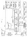
- FIG. 1is a block diagram of an exemplary architecture of a network suitable for practicing the present invention
- FIG. 2is a block diagram of a computing system environment suitable for use in implementing the present invention
- FIG. 3is a more detailed block diagram of a computing system suitable for use in implementing the present invention.
- FIG. 4is a schematic diagram of computer and telecommunications equipment suitable to implement the present invention.
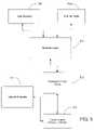
- FIG. 5is an architectural diagram depicting the layers of the present invention.
- FIG. 6is a flow chart for an exemplary implementation of the present invention.
- FIG. 7is a block diagram illustrating the components of the present invention.
- the present inventionis directed to a system and method for segregating business logic from computing device specific logic to minimize the impact of device changes, and to facilitate the implementation of business logic across multiple or dissimilar computing devices.
- the particular embodiments described hereinare intended in all respects to be illustrative rather than restrictive. Alternative embodiments will become apparent to those skilled in the art to which the present invention pertains without departing from its scope. Accordingly, the system and method of the present invention will be described with reference to telecommunications. More particularly, the present invention will be described with reference to routing switches and their associated configuration. Despite the embodiment described herein, it would be understood by those skilled in the art that the present invention can be implemented in hardware, software, firmware, or a combination thereof.
- the present inventionprovides the automated generation of commands or other data to populate tables of a database.
- the automated generation process of the present inventionfirst entails separating business logic from device specific logic. This is followed by defining how incoming data is organized, then identifying and setting default data parameters. The format for the output data is also defined and finally command generating object oriented classes are implemented in program source code, to execute on one or more computer systems and subsequently generate specific commands for data tables of the network devices.
- the present inventionmay be described in the general context of computer-executable instructions, such as program modules, being executed by one or more computing devices in a network environment.
- a networkincludes several similar or dissimilar devices connected together by some transport medium, which enables communication between the devices by using a predefined protocol.
- Those skilled in the artwill appreciate that the present invention may be practiced within a variety of network configuration environments and on a variety of computing devices, including hand-held devices, consumer electronics, and the like.
- the inventionalso may be practiced in a wireless computing environment.
- operating architecture 100an exemplary architecture for implementing the present invention is shown and generally designated as operating architecture 100 .
- the network architecture 100is merely one example of a suitable architecture and is not intended to suggest any limitation as to the scope of use or functionality of the invention. Additionally, the network architecture 100 should not be interpreted as having any dependency or requirement relating to any one or combination of components illustrated in FIG. 1 .
- An exemplary network 100 for implementing the inventionincludes a public or private network 112 , such as the Internet, Virtual Private Network (VPN) or other such arrangement, that enables multiple devices to be locally or remotely interconnected to facilitate communication between them.
- the Internetis a network of networks that enables one computing system to access virtually any other computing system, as well as any database and/or any type of information, anywhere in the world, so long as requisite devices have access to the Internet.
- VPNotherwise referred to as a Software-Defined Network (SDN), typically is used by large user organizations that have sites which are geographically dispersed. A terminating location in each of a multi-site enterprise is identified and a level of bandwidth required by each is determined.
- SDNSoftware-Defined Network
- Dedicated access circuitsare then established between each point of termination and the closest VPN-capable InterExchange Carrier (IXC) Point Of Presence (POP).
- IXCInterExchange Carrier
- POPPoint Of Presence
- the present inventionoperates with a variety of connected devices in a network environment, as discussed and illustrated in FIG. 1 .
- a hosting server 102 or multiple serversprovide a central store or repository for the software programs and data required to provide network switch configuration and operations.
- One or more client computers 104 a , 104 bprovide a user interface and may be used to execute portions or the entire program modules of the present invention.
- the client computers 104 a , 104 bare connected to the hosting server 102 on a LAN 114 .
- LAN 114is in turn connected to an external telecommunications network 112 .
- the devices on the telecommunications networkwill be described with reference also to FIG. 1 . Each device is essentially connected to the network with a dedicated connection or through some other intermediary method.
- a dedicated or direct access connection in this contextis a connection to a regional or national backbone provider, bypassing any local service providers.
- Direct accesscan be on the basis of a number of alternatives including, but not limited to, Dataphone Digital Service (DDS), Trunk Carrier (T-Carrier) (e.g., Fractional T1, T1, T3, etc.).
- DDSDataphone Digital Service
- T-CarrierTrunk Carrier
- the connection from the network 112 to the LAN 114is linked to a network interface device, such as router/switch 106 , which performs the functions of routing and switching between the external network 112 and the corporate network 114 .
- a routeris an intelligent device that supports connectivity between like and disparate LANs. Routers also can provide access to various WANs, such as X.25, ISDN and Frame Relay. Routers generally provide connectivity, addressing and switching.
- LECLocal Exchange Carrier
- COCentral Office
- LECsmay be connected to networks of Interexchange carriers (IXCs or IECs), designated as IXC Network 116 .
- IXCsInterexchange carriers
- IXC Network 116Within an IXC network 116 , exist Point Of Presence (POP) offices, which are represented by the switches 122 a , 122 b .
- POPPoint Of Presence
- IXCsprovide for long-haul, long-distance connections across Local access and Transport Area (LATA) boundaries.
- LEC network 116is connected to the LEC through a tandem switch 118 .
- LECsalso contain a number of Private Branch Exchanges (PBX) 110 , which are connected via a POP office switch 108 to the external network 112 .
- PBXPrivate Branch Exchanges
- network architecture 100provides the infrastructure for the system and method of the present invention.
- FIG. 2To a discussion on an operating environment such as network clients 104 a , 104 b , the server 102 , or any other computing device that could be used to implement the present invention.
- operating environment 210an exemplary operating environment for implementing the present invention is shown and designated generally as operating environment 210 .
- operating environment 210typically includes a processor 212 and a memory 214 .
- memory 214may be volatile (e.g., random access memory (RAM)), non-volatile (e.g., read only memory (ROM), flash memory, etc.) or some combination of volatile and non-volatile memory.
- operating environment 210also may have mass storage (removable and/or nonremovable) such as magnetic tape, magnetic disks, and/or optical disks.
- the operating environment 210further typically includes an operating system which is resident on the memory 214 and executes on the processor 212 .
- Operating environment 210also may include an input 216 and/or an output, such as a display 218 .
- input 216may be any one of a variety of inputs known in the art, or any combination thereof, such as a keypad, mouse, pen, voice input device, touch input device, and the like.
- output 218may be any one or a combination of a variety of outputs known in the art such as a display, speakers, printer, and the like. All such devices are well known in the art and need not be discussed at length herein. It will be understood and appreciated that various inputs or outputs may be utilized with the operating environment of the present invention and such variations are contemplated to be within the scope hereof.
- PCpersonal computer
- FIG. 3an exemplary PC operating environment is illustrated in FIG. 3 .
- FIG. 3illustrates an example of a suitable operating environment 320 on which the present invention may be implemented.
- Operating environment 320is a computing system environment and is merely one example of a suitable operating environment.
- Computing system environment 320is not intended to suggest any limitation as to the scope of use or functionality of the present invention. Further, computing system environment 320 should not be interpreted as having any dependency or requirement relating to any one of the components, or any combination thereof, illustrated in the exemplary computing environment 320 .
- the present inventionmay be described in the general context of computer-executable instructions, such as program modules, being executed by a computer.
- program modulesinclude routines, programs, objects, components, data structures, and the like, that perform particular tasks or implement particular abstract data types.
- Examples of well known computing systems, environments, and/or configurations that may be suitable for use with the present inventioninclude, but are not limited to, personal computers, server computers, hand-held or laptop devices, multiprocessor systems, microprocessor-based systems, programmable consumer electronics, network PCs, minicomputers, mainframe computers, and the like.
- the inventionalso may be practiced in distributed computing environments wherein tasks are performed by remote processing devices that are linked through a communications network.
- program modulesmay be located in both local and remote computer storage media including memory storage devices.
- an exemplary system for implementing the present inventionincludes a general purpose computing device in the form of a computer 322 .
- Components of computer 322include, but are not limited to, a central processing unit (CPU) 324 , a system memory 326 , an input/output (I/O) Interface 328 , and a system bus 330 that couples various system components with one another, including coupling the system memory with the processing unit.
- the system bus 330may be any of several types of bus structures including a memory bus or memory controller, a peripheral bus, and a local bus using any of a variety of bus architectures.
- such architecturesinclude Industry Standard Architecture (ISA) bus, Micro Channel Architecture (MCA) bus, Enhanced ISA (EISA) bus, Video Electronics Standards Association (VESA) local bus, and Peripheral Component Interconnect (PCI) bus, also known as Mezzanine bus.
- ISAIndustry Standard Architecture
- MCAMicro Channel Architecture
- EISAEnhanced ISA
- VESAVideo Electronics Standards Association
- PCIPeripheral Component Interconnect
- Computer 322typically includes a variety of computer readable media.
- computer readable mediamay comprise computer storage media and communication media.
- Computer storage mediaincludes both volatile and nonvolatile storage media, and removable and non-removable storage media, each implemented in any method or technology for storage of information such as computer readable instructions, data structures, program modules or other data. Examples of computer storage media include, but are not limited to, RAM, ROM, electronically erasable programmable read-only memory (EEPROM), flash memory or other memory technology, CD-ROM, digital versatile disks (DVD) or other optical disk storage, magnetic cassettes, magnetic tape, magnetic disk storage or other magnetic storage devices, or any other medium which can be used to store the desired information and which can be accessed by computer 322 .
- RAMrandom access memory
- ROMread-only memory
- EEPROMelectronically erasable programmable read-only memory
- DVDdigital versatile disks
- Communication mediatypically embodies computer readable instructions, data structures, program modules or other data in a modulated data signal such as a carrier wave or other transport mechanism and includes any information delivery media.
- modulated data signalmeans a signal that has one or more of its characteristics set or changed in such a manner as to encode information in the signal.
- communication mediaincludes wired media such as a wired network or direct wired connection, and wireless media such as acoustic, RF, infrared and other wireless media. It will be understood and appreciated that combinations of any of the above also are included within the scope of computer readable media.
- the system memory 326includes computer storage media in the form of volatile and/or nonvolatile memory such as ROM 332 (nonvolatile) and RAM 334 (volatile).
- ROM 332nonvolatile
- RAM 334volatile
- BIOSbasic input/output system
- BIOSbasic input/output system
- RAM 334typically contains data and/or program modules that are presently being operated on by processing unit 324 , and/or are immediately accessible to the processing unit.
- FIG. 3illustrates operating system 338 , application programs 340 , other program modules 342 , and program data 344 as data and/or program modules stored in RAM 334 .
- the I/O Interface 328includes a variety of components that provide physical connections and communications between peripheral devices and the processing unit 324 , system bus 330 and system memory 326 of computer 322 .
- I/O Interface 328may include network interface 346 , video interface 348 , Small Computer System Interface (SCSI) or Integrated Device Electronics (IDE) Interface 350 , or other mass storage-type interface, and serial, parallel, USB, or other bus-type port interface 352 .
- I/O Interface 328may include interface components that are integrated, provided as an add-on hardware device, provided as a software component, or as a combination of software and hardware. All such variations are contemplated to be within the scope hereof.
- the computer 322also may include other computer storage media which may be removable and/or nonremovable, volatile and/or nonvolatile.
- FIG. 3illustrates other computer storage media as a hard disk drive 354 , a magnetic disk drive 356 and an optical disk drive 360 .
- Hard disk drive 354reads from and/or writes to nonremovable, nonvolatile magnetic media.
- Magnetic disk drive 356reads from and/or writes to a removable, nonvolatile magnetic disk 358 .
- Optical disk drive 360reads from and/or writes to a removable, nonvolatile optical disk 362 such as a CD ROM, DVD or other optical media.
- removable/nonremovable, volatile/nonvolatile computer storage mediathat can be used in the exemplary operating environment include magnetic tape cassettes, flash memory cards, digital video tape, Bernoulli cartridges, solid state RAM, solid state ROM, and the like.
- Computer storage mediatypically is connected to the system bus 330 through I/O Interface 328 .
- I/O Interface 328Various types of I/O interfaces may be used in the exemplary operating environment 320 and are known to those of skill in the art.
- the hard disk drive 354 , magnetic disk drive 356 , and optical disk drive 360may be connected to the system bus 330 by a SCSI 350 or IDE Interface. It will be understood and appreciated that the above interfaces are merely examples of interfaces that may be suitable for the exemplary computing system 320 and should not be viewed as limitations of the present invention.
- hard disk drive 354is illustrated as storing operating system 364 , application programs 366 , other program modules 368 , and program data 370 . Note that these components either can be the same as or different from operating system 338 , application programs 340 , other program modules 342 , and program data 344 .
- the operating system, application programs and the like that are stored in RAMare portions of the corresponding systems, programs, or data read from hard disk drive 354 , the portions varying in size and scope depending on the functions desired.
- Operating system 364 , application programs 366 , other program modules 368 , and program data 370are given different numbers herein to illustrate that, at a minimum, they are different copies.
- a usermay enter commands and information into the computer 322 through input devices such as a keyboard 372 and pointing device 374 , commonly referred to as a mouse, trackball, or touch pad.
- Other input devicesmay include a microphone, joystick, game pad, satellite dish, scanner, or the like.
- I/O Interface 328that is coupled to the system bus 330 , more particularly through port interface 352 .
- input devicesmay be connected by interface components and bus structures, such as a parallel port, game port or a universal serial bus (USB) port.
- a monitor 376 or other type of display devicealso is connected to system bus 330 via an interface such as I/O Interface 328 .
- computersalso may include other peripheral output devices such as speakers 378 and printer 380 , which also may be connected through I/O interface 328 .
- peripheral output devicessuch as speakers 378 and printer 380
- I/O interface 328a typical I/O interface for an output peripheral device such as monitor 376 is a video interface 348 .
- the computer 322 in the present inventionis capable of operating in a networked environment using logical connections to one or more remote computers, such as remote computer 382 .
- the remote computer 382may be a personal computer, a server, a router, a network PC, a peer device or other common network node, and typically includes many or all of the elements described above relative to the computer 322 .
- the logical connections depicted in FIG. 3include a local area network (LAN) 384 and a wide area network (WAN) 386 , but may also include other networks.
- LANlocal area network
- WANwide area network
- Such networking environmentsare commonplace in offices, enterprise-wide computer networks, intranets and the Internet.
- the computer 322When used in a LAN networking environment, the computer 322 is connected to the LAN 384 through a network interface 346 or adapter. When used in a WAN networking environment, the computer 322 typically includes a modem 388 or other means for establishing communications over the WAN 386 , such as the Internet.
- the modem 388which may be internal or external, may be connected to the system bus 330 via the I/O Interface 328 , or other appropriate mechanism. It will be understood and appreciated by those of skill in the art that the network connections shown are exemplary and other means of establishing a communications link between the computers may be used.
- the BIOS 336which is stored in the ROM 332 instructs the processing unit 324 to load the operating system, or necessary portion thereof, from the hard disk drive 354 into the RAM 334 .
- the processing unit 324executes the operating system code and causes the visual elements associated with the user interface of the operating system 338 to be displayed on the monitor 376 .
- the program code and relevant dataare read from the hard disk drive 354 and the necessary portions are copied into RAM 334 , the copied portion represented herein by reference numeral 340 .
- FIG. 4depicts the components of a network architecture that can be used to implement the present invention.
- a client computer 104 aa server 102 and any switch 108 , 118 , 122 a , or 122 b.
- the present inventionmay be used on a personal computer 408 , in conjunction with or on a server 406 to provide and access data stored on a disk 404 .
- the illustrated system of FIG. 4enables the set up of call routing in one or more telecommunications switches 400 .
- a switch 400provides telecommunications services in a metropolitan statistical area (MSA) or other geographic area.
- MSAmetropolitan statistical area
- a switch 400could be a voice-over-IP routing switch (often referred to herein as merely “switch” or “switches”) such as the service manager switches manufactured by GTE or the Service Gateway Service manager switches manufactured by Telcordia.
- Each switchsupports a plurality of data tables that contain, among other things, call routing information or data used to route calls serviced by the switch.
- Two such tablesare the Digit Translator and Group Translator tables which were earlier identified.
- the process for setting up a new switch 400 or implementing a new service on an existing switch 400begins when an operator or administrator at a telecommunications company such as a network translations person uses an application program on the computer 408 to enter or access information on the server computer 406 .
- the computer 408either directly or through the server 406 is able to load the tables of the switch 400 with information that is initially stored on disk 404 .
- the process that occurs on a computing system such as computer 408 to enable the creation, manipulation and formatting of the necessary data for switch 400is best described with reference to a systems architecture of the present invention.
- FIG. 5illustrates a high level architecture of the layers involved in an implementation of the present invention.
- a user interface 502 in combination with some other external feed 504are the source of desired system changes.
- user interface 502allows a user to input desired service changes to the system, such as specifying a requirement to add new area codes to an MSA.
- External feed 504provides information on the current state of the system. The combined information of user request and system status then enables a determination of what is needed to allow the user's desired changes to be accomplished.
- a business layer 506provides an information store for business driven demands. As previously stated, these demands are independent of the network demands. In other words, this layer is in no way concerned with how to accomplish the changes to the system rather, the focus is on what those changes need to do.
- the user interface 502 request and external feed 504 informationare passed to the business layer 506 , and the separation process of business logic and system logic takes place. The required changes to the system are determined at this level and then passed on to a provisioning layer 508 .
- all communications between the various layersare bi-directional. For example, there is communication in the form of responses from the business layer 506 to the user interface 502 and external feed 504 . Similarly, there is a response from the provisioning layer 508 to the business layer 506 and so on.
- Provisioning layer 508enables the UCG of the present invention to generate commands that will implement the desired system changes. These commands must then be passed on to the switches on the network. This is accomplished by providing the commands to a network delivery layer 512 .
- Network layer 512in combination with network elements 510 , deliver the commands to the switch.
- Network elements 510are parts of the network that interact with the delivery mechanisms to the switch. For example, while it is clear which particular switch on the network needs to be loaded with information, it will still be necessary at the point when delivery is to be implemented, to obtain other network information such as, the address or packet routing mechanism to reach the particular switch.
- FIG. 6illustrates the progression of information from the point where a business demand for a service is initiated, through to the implementation on the network switches.
- a business demandis shown at step 602 and initiates the process.
- business demandscan arise from a number of situations; for example, voice activated dialing service.
- a separation of business logic and network or device logicmust first occur as shown at step 604 and 606 , this enables changes to be made to one set of logic without necessarily impacting the other. In other words, the logic or actions that must be specifically performed by individual switches on the network are separately considered.
- a Universal Command Generator (UCG) program of the present inventionreceives from step 604 the actions that must be performed on a switch.
- commandsare generated for each of the affected switches.
- commandsare generated for a switch A.
- Commandsare also generated for switch B, at step 612 .
- Each of the command sets 610 , 612are ultimately loaded into the appropriate switch. It should be understood that switch A and switch B, could be identical models but with different fields or could be dissimilar brands with nothing in common.
- the process for setting up a new switch or updating an existing switchbegins when an operator or administrator at a telecommunications company such as a network translations person uses a computer to enter information.
- the user entered informationrelates to call routing criteria for an MSA of interest.
- This informationwould include NPAs, NXXs, dialing patterns, trunk groups, terminating end offices, and files that are used to differentiate between local and long distance calls.
- This informationis transferred to storage on a server computer where it is analyzed by an MSA build utility program or other program residing on or accessible by the server computer.
- the server computerthen automatically creates output files, including a Digit Translator table and a Group Translator table, for setting up core call routing for the new switch or the new MSA being added to the switch.
- the output filesare transferred from the server computer to the user computer.
- An operator of the user computermay add additional call routing data and/or files to the output files and then transfers the completed files for downloading to the switch.
- These filesmay be internally organized in any one of several formats such as, a particular ordering of the supplied data.
- a usertypically provides certain MSA and switch information to identify the MSA for which call routing is to be created (for example, New York).
- the useralso provides an ID for the switch handling call routing for the MSA (for example, 2055), and MSA name description (for example, New York).
- Thisis usually followed by providing certain NPA and NXX information for the selected MSA.
- the userenters the NPAs owned by the telecommunications company providing services in the area.
- the useralso enters the associated internal and external dialing patterns for each NPA.
- Provided for each NPAare associated NXXs, assigned portability indicators and a locality name for each NXX. All of this information is organized in an order that is suitable for the intended switch tables.
- the Digit Translator tablewhich includes information used to group sets of phone number digits together, where these are phone numbers that should be routed and charged the same, is one such table.
- Another tableis a Group Translator table, which includes information used for routing and charging calls based on the grouping of digits in the Digit Translator table. The data is organized according to a format that is specifically suited for input into each individual table. Examples of completed data files for both the Digit Translator and Group Translator tables, arranged with pipe (‘
- UCGgenerates commands to populate data tables such as the Group Translator and Digit Translator tables, which were earlier discussed.
- the UCGcomprises four main components namely, a service interpreter 702 , a command factory 704 , a command builder 706 and one or more commands 708 .
- UCGis essentially an architecture that provides a set of reusable object oriented classes for use in network element command generation. As described earlier, current systems intermingle the business logic of a particular system with the command generation for a network device. UCG allows systems to segregate business logic from the technology specific record creation that is needed for network switches.
- UCG serverprovides a repository for device specific commands that are generated by UCG. As such, a single UCG server may be designated for each of a variety of network switches. In other instances, when the application consists of multiple services, and each service is responsible for updating different tables in a single switch, a UCG server may be designated for each service. In any case, every UCG server will implement the following four object oriented classes: ServiceInterpreter ⁇ ⁇ , CommandBuilderFactory ⁇ ⁇ , CommandBuilder ⁇ ⁇ , and Command ⁇ ⁇ . Each of these classes are represented by the earlier identified components respectively: service interpreter 702 , command factory 704 , command builder 706 and command 708 .
- inputting customer or business logic 710is the initiating process.
- Business logic 710has no relationship to the logic that will run the network.
- data and a service name corresponding to the business logic 710are passed to service interpreter 702 .
- Service interpreter 702makes the received data network specific and uses the service name to obtain the names of all the switch tables that need to be populated in order to provide the service. In other words, service interpreter 702 determines the commands that need to be built for a particular service.
- UCGis implemented with a program source code by a developer.
- the developer's programutilizes known techniques within the art to access the object modules or other similar implementations of UCG, and is generally referred to as a client application.
- the ServiceInterpreter ⁇ ⁇ classprovides the interface that a client application will use to access the UCG server.
- a list of available telecommunication servicesare stored in a data base table 712 .
- Also storedis a list of the tables within each network element, which have to be built.
- the ServiceInterpreter ⁇ ⁇ classwhich corresponds to service interpreter 702 , is invoked with data and a service name. When this class is invoked there is a lookup to determine the applicable tables to be populated for the specified service. The names of these applicable tables are then passed on to the other UCG classes.
- Service interpreter 702sends the table names to command factory 704 .
- Command factory 704holds a list of pointers to individual command builders 706 .
- command factory 704sends command builder pointers back to the service interpreter 702 .
- a pointer to command builder 706is sent for each one of the received table names.
- CommandBuilderFactory ⁇ ⁇In operation, only a single instance of CommandBuilderFactory ⁇ ⁇ object class is created and allowed per process on the computer system.
- This command builder factory classis responsible for managing all of the different CommandBuilder ⁇ ⁇ object classes.
- CommandBuilderFactory ⁇ ⁇accepts a table name as an argument and returns a pointer to the appropriate CommandBuilder ⁇ ⁇ .
- Command builder 706contains the logic to create the command that is appropriate to the service.
- Service interpreter 702calls command builder 706 with the appropriate data for the service.
- Command builder 706then builds a command which becomes a row entry in a designated table.
- CommandBuilder ⁇ ⁇provides four virtual methods—buildCommand( ), refreshList( ), insertCommands( ) and deleteCommands( ).
- a single CommandBuilder classis derived for each network element table. For example, with reference back to MSA and the two tables Digit Translator and Group Translator, there would be two derived classes that inherit from the base class CommandBuilder ⁇ ⁇ namely, DigitCommandBuilder and GroupCommandBuilder. As such, each of these derived classes would populate its own table.
- each classmust implement the buildCommand( ) method, which returns a Command 708 .
- the buildCommand( ) methodmust be able to handle all of the different services that could have originated from the service interpreter 702 .
- each Command 708 that gets returnedis different depending on the service. Any successfully built Command 708 , is stored in an internal linked list, which continues to grow until the client application invokes the insertCommands( ) method. InsertCommands( ) method pops each Command 708 off the linked list and causes a record to be created in the appropriate table of the network element, the switch.
- the deleteCommand( ) methodcauses all Command 708 to be deleted from the linked list.
- the refreshList( ) methodaccepts as an argument, the identification of a linked list that is to be refreshed. In some cases where the network element table is sufficiently small, the table is read into volatile memory for faster access. However, because such tables can and do change, a method is provided to refresh the information.
- service interpreter 702instructs command builder 706 to insert the commands into the appropriate tables to be sent to the switch.
- a call from command builder 706 to command 708causes the commands to be inserted in the tables.
- Command 708represents a row in a specific table.
- Command ⁇ ⁇is the lowest level class of the present invention with two virtual methods—buildTupleTxt( ) and insert( ).
- An inherited Command ⁇ ⁇ classis created for each network element table that is to be automated, in the system.
- the insert( ) methodinserts a record into the network element table.
- the buildTupleTxt( ) methodbuilds the command text field (cmd_txt) in the network element table.
- Cmd_txtcontains the actual command or record that will be sent to the network element and actually inserted into one of the element's tables.
- BuildTupleTxt( ) methodbuilds a string of the member variables of the derived class with a pipe (
- UCGcan be used to build commands for multiple tables in a particular switch.
- UCGcan create batch files of commands to be transmitted to a switch.
- UCGcan also generate commands, passing them in real time to a switch via an interface such as a CORBA interface.
- UCGcan be implemented as part of a core server or completely separated. Even further, UCG can be used to build commands that are simultaneously passed to switches from different manufacturers.
- UCGcan also be used to populate any data tables other than those relating to switches, as long as default values and rules for populating the tables can be adequately described and specified.
- the system and method of the present inventionprovides numerous advantages which include but are not limited to, minimizing the impact of device changes and facilitating the implementation of business logic across multiple or dissimilar computing devices, by segregating business logic from the specific logic of the computing devices.
- a further advantage of the present inventionlies in the automated generation of commands or other data to populate tables of a database.
- An even further advantage of the present inventionis the fact that switches on a telecommunications network can be updated or programmed with minimal effort once services and associated commands have been identified for the available switch models.
Landscapes
- Engineering & Computer Science (AREA)
- Computer Networks & Wireless Communication (AREA)
- Signal Processing (AREA)
- Data Exchanges In Wide-Area Networks (AREA)
Abstract
Description
- 203636|2|9|10|10|1|misdialing10_rte|misdialing10 rte∥
- 203636|203201|203201|10|10|1|oper_inter|dms_inter∥
- 203636|203202|203202|10|10|2|oper_inter|dms_inter∥
- 203636|203204|203204|10|10|2|oper_inter|dms_inter∥
- 203636|203205|203205|10|10|2|oper_inter|dms_inter∥
- 203636|203206|203206|10|10|1|oper_inter|dms_inter∥
- 203636|203207|203207|10|10|2|oper_inter|dms_inter∥
- 203636|203208|203208|10|10|2|oper_inter|dms_inter∥
- 203636|203209|203209|10|10|2|oper_inter|dms_inter∥
- 203636|203210|203210|10|10|2|oper_inter|dms_inter∥
- 203636|203213|203213|10|10|1|oper_inter|dms_inter∥
- 203636|203214|203214|10|10|1|oper_inter|dms_inter∥
- 203636|203215|203215|10|10|1|oper_inter|dms_inter∥
- 203636|203216|203216|10|10|1|oper_inter|dms_inter∥
- 203636|203217|203217|10|10|1|oper_inter|dms_inter∥
- 203636|203218|203218|10|10|1|oper_inter|dms_inter∥
- 203636|203220|203220|10|10|2|oper_inter dms_inter∥
- 203636|203221|203221|10|10|2|oper_inter|dms_inter∥
- 203636|203222|203222|10|10|2|oper_inter dms_inter∥
Group Translator
translator_name|group name|prefix_type_name|originating_class_code_name|originating_area_name|secondary_classmark_list|geographic_area_name|Charge_class_name |next_translator_type|next_translator_name|delete_digit_count|prepend|digits|build_out_digits|build_out_digits_code_length|routing_class_type|routing_class_name|comment|action
203636|dms_inter|dddplus|@|@|@|@|interlata∥∥∥|2|nyc—250_rte∥
203636|dms_inter|noprefix|@|@|@|@|norecord∥∥∥|2|misdialing_cause—10_rte∥
203636|dms_inter|noprefix|@|@|@|@|norecord∥∥∥|2|misdialing_cause—10_rte∥
203636|dms_intra|dddplus|@|@|@|@|interlata∥∥∥|2|nyc—250_rte∥
203636|dms_intra|noprefix|@|@|@|@|norecord∥∥∥|misdialing_cause—10rte∥
203636|HNPA —102—10d|DDDPLUS|@|@|@|@|norecord ∥∥∥|2|misdialing_cause_N8_N9_rte∥
203636|HNPA —102—10D|NOPREFIX|@|@|@|@|local∥∥∥|1∥|
203636|hnpa —102—7d|dddplus|@|@|@|@|norecord∥∥∥|2|misdialing_cause_n8_n9_rte∥
203636|hnpa —102—7d|noprefix|@|@|@|@|local∥∥|203∥1∥|
203636|hnpa—203—10d|dddplus|@|@|@|@|norecord∥∥∥|2|misdialing_cause_n8_n9_rte∥
203636|hnpa—203—10d|noprefix|@|@|@|@|local∥∥∥|1∥|
Claims (3)
Priority Applications (1)
| Application Number | Priority Date | Filing Date | Title |
|---|---|---|---|
| US10/083,064US7688960B1 (en) | 2002-02-26 | 2002-02-26 | Method and system for separating business and device logic in a computing network system |
Applications Claiming Priority (1)
| Application Number | Priority Date | Filing Date | Title |
|---|---|---|---|
| US10/083,064US7688960B1 (en) | 2002-02-26 | 2002-02-26 | Method and system for separating business and device logic in a computing network system |
Publications (1)
| Publication Number | Publication Date |
|---|---|
| US7688960B1true US7688960B1 (en) | 2010-03-30 |
Family
ID=42044630
Family Applications (1)
| Application Number | Title | Priority Date | Filing Date |
|---|---|---|---|
| US10/083,064Active2029-01-20US7688960B1 (en) | 2002-02-26 | 2002-02-26 | Method and system for separating business and device logic in a computing network system |
Country Status (1)
| Country | Link |
|---|---|
| US (1) | US7688960B1 (en) |
Cited By (70)
| Publication number | Priority date | Publication date | Assignee | Title |
|---|---|---|---|---|
| US20100246388A1 (en)* | 2009-03-26 | 2010-09-30 | Brocade Communications Systems, Inc. | Redundant host connection in a routed network |
| US20110125908A1 (en)* | 2009-11-24 | 2011-05-26 | Pamela Zave | Method and apparatus for programming session initiation protocol back-to-back user agents |
| US20120005654A1 (en)* | 2004-09-30 | 2012-01-05 | Graham Kevin P | Repository relationship programming |
| US20120016973A1 (en)* | 2010-07-16 | 2012-01-19 | Brocade Communications Systems, Inc. | Configuration orchestration |
| US20140280898A1 (en)* | 2013-03-15 | 2014-09-18 | Cisco Technology, Inc. | Allocating computing resources based upon geographic movement |
| US8867552B2 (en) | 2010-05-03 | 2014-10-21 | Brocade Communications Systems, Inc. | Virtual cluster switching |
| US8879549B2 (en) | 2011-06-28 | 2014-11-04 | Brocade Communications Systems, Inc. | Clearing forwarding entries dynamically and ensuring consistency of tables across ethernet fabric switch |
| US8885641B2 (en) | 2011-06-30 | 2014-11-11 | Brocade Communication Systems, Inc. | Efficient trill forwarding |
| US8885488B2 (en) | 2010-06-02 | 2014-11-11 | Brocade Communication Systems, Inc. | Reachability detection in trill networks |
| US8948056B2 (en) | 2011-06-28 | 2015-02-03 | Brocade Communication Systems, Inc. | Spanning-tree based loop detection for an ethernet fabric switch |
| US8989186B2 (en) | 2010-06-08 | 2015-03-24 | Brocade Communication Systems, Inc. | Virtual port grouping for virtual cluster switching |
| US8995444B2 (en) | 2010-03-24 | 2015-03-31 | Brocade Communication Systems, Inc. | Method and system for extending routing domain to non-routing end stations |
| US8995272B2 (en) | 2012-01-26 | 2015-03-31 | Brocade Communication Systems, Inc. | Link aggregation in software-defined networks |
| US9001824B2 (en) | 2010-05-18 | 2015-04-07 | Brocade Communication Systems, Inc. | Fabric formation for virtual cluster switching |
| US9007958B2 (en) | 2011-06-29 | 2015-04-14 | Brocade Communication Systems, Inc. | External loop detection for an ethernet fabric switch |
| US9143445B2 (en) | 2010-06-08 | 2015-09-22 | Brocade Communications Systems, Inc. | Method and system for link aggregation across multiple switches |
| US9154416B2 (en) | 2012-03-22 | 2015-10-06 | Brocade Communications Systems, Inc. | Overlay tunnel in a fabric switch |
| US9231890B2 (en) | 2010-06-08 | 2016-01-05 | Brocade Communications Systems, Inc. | Traffic management for virtual cluster switching |
| US9246703B2 (en) | 2010-06-08 | 2016-01-26 | Brocade Communications Systems, Inc. | Remote port mirroring |
| US9270572B2 (en) | 2011-05-02 | 2016-02-23 | Brocade Communications Systems Inc. | Layer-3 support in TRILL networks |
| US9270486B2 (en) | 2010-06-07 | 2016-02-23 | Brocade Communications Systems, Inc. | Name services for virtual cluster switching |
| US9350680B2 (en) | 2013-01-11 | 2016-05-24 | Brocade Communications Systems, Inc. | Protection switching over a virtual link aggregation |
| US9374301B2 (en) | 2012-05-18 | 2016-06-21 | Brocade Communications Systems, Inc. | Network feedback in software-defined networks |
| US9401861B2 (en) | 2011-06-28 | 2016-07-26 | Brocade Communications Systems, Inc. | Scalable MAC address distribution in an Ethernet fabric switch |
| US9401872B2 (en) | 2012-11-16 | 2016-07-26 | Brocade Communications Systems, Inc. | Virtual link aggregations across multiple fabric switches |
| US9401818B2 (en) | 2013-03-15 | 2016-07-26 | Brocade Communications Systems, Inc. | Scalable gateways for a fabric switch |
| US9407533B2 (en) | 2011-06-28 | 2016-08-02 | Brocade Communications Systems, Inc. | Multicast in a trill network |
| US9413691B2 (en) | 2013-01-11 | 2016-08-09 | Brocade Communications Systems, Inc. | MAC address synchronization in a fabric switch |
| US9450870B2 (en) | 2011-11-10 | 2016-09-20 | Brocade Communications Systems, Inc. | System and method for flow management in software-defined networks |
| US9461840B2 (en) | 2010-06-02 | 2016-10-04 | Brocade Communications Systems, Inc. | Port profile management for virtual cluster switching |
| US9524173B2 (en) | 2014-10-09 | 2016-12-20 | Brocade Communications Systems, Inc. | Fast reboot for a switch |
| US9544219B2 (en) | 2014-07-31 | 2017-01-10 | Brocade Communications Systems, Inc. | Global VLAN services |
| US9548926B2 (en) | 2013-01-11 | 2017-01-17 | Brocade Communications Systems, Inc. | Multicast traffic load balancing over virtual link aggregation |
| US9548873B2 (en) | 2014-02-10 | 2017-01-17 | Brocade Communications Systems, Inc. | Virtual extensible LAN tunnel keepalives |
| US9565113B2 (en) | 2013-01-15 | 2017-02-07 | Brocade Communications Systems, Inc. | Adaptive link aggregation and virtual link aggregation |
| US9565099B2 (en) | 2013-03-01 | 2017-02-07 | Brocade Communications Systems, Inc. | Spanning tree in fabric switches |
| US9565028B2 (en) | 2013-06-10 | 2017-02-07 | Brocade Communications Systems, Inc. | Ingress switch multicast distribution in a fabric switch |
| US9602430B2 (en) | 2012-08-21 | 2017-03-21 | Brocade Communications Systems, Inc. | Global VLANs for fabric switches |
| US9608833B2 (en) | 2010-06-08 | 2017-03-28 | Brocade Communications Systems, Inc. | Supporting multiple multicast trees in trill networks |
| US9628407B2 (en) | 2014-12-31 | 2017-04-18 | Brocade Communications Systems, Inc. | Multiple software versions in a switch group |
| US9628293B2 (en) | 2010-06-08 | 2017-04-18 | Brocade Communications Systems, Inc. | Network layer multicasting in trill networks |
| US9626255B2 (en) | 2014-12-31 | 2017-04-18 | Brocade Communications Systems, Inc. | Online restoration of a switch snapshot |
| US9699029B2 (en) | 2014-10-10 | 2017-07-04 | Brocade Communications Systems, Inc. | Distributed configuration management in a switch group |
| US9699001B2 (en) | 2013-06-10 | 2017-07-04 | Brocade Communications Systems, Inc. | Scalable and segregated network virtualization |
| US9699117B2 (en) | 2011-11-08 | 2017-07-04 | Brocade Communications Systems, Inc. | Integrated fibre channel support in an ethernet fabric switch |
| US9716672B2 (en) | 2010-05-28 | 2017-07-25 | Brocade Communications Systems, Inc. | Distributed configuration management for virtual cluster switching |
| US9736085B2 (en) | 2011-08-29 | 2017-08-15 | Brocade Communications Systems, Inc. | End-to end lossless Ethernet in Ethernet fabric |
| US9742693B2 (en) | 2012-02-27 | 2017-08-22 | Brocade Communications Systems, Inc. | Dynamic service insertion in a fabric switch |
| US9769016B2 (en) | 2010-06-07 | 2017-09-19 | Brocade Communications Systems, Inc. | Advanced link tracking for virtual cluster switching |
| US9800471B2 (en) | 2014-05-13 | 2017-10-24 | Brocade Communications Systems, Inc. | Network extension groups of global VLANs in a fabric switch |
| US9806949B2 (en) | 2013-09-06 | 2017-10-31 | Brocade Communications Systems, Inc. | Transparent interconnection of Ethernet fabric switches |
| US9806906B2 (en) | 2010-06-08 | 2017-10-31 | Brocade Communications Systems, Inc. | Flooding packets on a per-virtual-network basis |
| US9807005B2 (en) | 2015-03-17 | 2017-10-31 | Brocade Communications Systems, Inc. | Multi-fabric manager |
| US9807007B2 (en) | 2014-08-11 | 2017-10-31 | Brocade Communications Systems, Inc. | Progressive MAC address learning |
| US9912614B2 (en) | 2015-12-07 | 2018-03-06 | Brocade Communications Systems LLC | Interconnection of switches based on hierarchical overlay tunneling |
| US9912612B2 (en) | 2013-10-28 | 2018-03-06 | Brocade Communications Systems LLC | Extended ethernet fabric switches |
| US9942097B2 (en) | 2015-01-05 | 2018-04-10 | Brocade Communications Systems LLC | Power management in a network of interconnected switches |
| US10003552B2 (en) | 2015-01-05 | 2018-06-19 | Brocade Communications Systems, Llc. | Distributed bidirectional forwarding detection protocol (D-BFD) for cluster of interconnected switches |
| US10038592B2 (en) | 2015-03-17 | 2018-07-31 | Brocade Communications Systems LLC | Identifier assignment to a new switch in a switch group |
| US10063473B2 (en) | 2014-04-30 | 2018-08-28 | Brocade Communications Systems LLC | Method and system for facilitating switch virtualization in a network of interconnected switches |
| US10171303B2 (en) | 2015-09-16 | 2019-01-01 | Avago Technologies International Sales Pte. Limited | IP-based interconnection of switches with a logical chassis |
| CN109474762A (en)* | 2018-09-18 | 2019-03-15 | 中国平安人寿保险股份有限公司 | Processing method, device, computer equipment and the storage medium for task of making house calls |
| US10237090B2 (en) | 2016-10-28 | 2019-03-19 | Avago Technologies International Sales Pte. Limited | Rule-based network identifier mapping |
| US10277464B2 (en) | 2012-05-22 | 2019-04-30 | Arris Enterprises Llc | Client auto-configuration in a multi-switch link aggregation |
| US10439929B2 (en) | 2015-07-31 | 2019-10-08 | Avago Technologies International Sales Pte. Limited | Graceful recovery of a multicast-enabled switch |
| US10454760B2 (en) | 2012-05-23 | 2019-10-22 | Avago Technologies International Sales Pte. Limited | Layer-3 overlay gateways |
| US10476698B2 (en) | 2014-03-20 | 2019-11-12 | Avago Technologies International Sales Pte. Limited | Redundent virtual link aggregation group |
| US10581758B2 (en) | 2014-03-19 | 2020-03-03 | Avago Technologies International Sales Pte. Limited | Distributed hot standby links for vLAG |
| US10579406B2 (en) | 2015-04-08 | 2020-03-03 | Avago Technologies International Sales Pte. Limited | Dynamic orchestration of overlay tunnels |
| US10616108B2 (en) | 2014-07-29 | 2020-04-07 | Avago Technologies International Sales Pte. Limited | Scalable MAC address virtualization |
Citations (9)
| Publication number | Priority date | Publication date | Assignee | Title |
|---|---|---|---|---|
| US5559877A (en)* | 1995-03-21 | 1996-09-24 | At&T | Automatic provisioning of trunking and routing parameters in a telecommunications network |
| US5634126A (en)* | 1992-08-28 | 1997-05-27 | Telefonaktiebolaget Lm Ericsson | Software program structure and method for modulizing the operations of a telecommunications system |
| US5875242A (en)* | 1996-07-26 | 1999-02-23 | Glaser; Lawrence F. | Telecommunications installation and management system and method |
| US5881131A (en)* | 1993-11-16 | 1999-03-09 | Bell Atlantic Network Services, Inc. | Analysis and validation system for provisioning network related facilities |
| US6246678B1 (en)* | 1997-02-13 | 2001-06-12 | Mitel Corporation | Data access server for PBX |
| US6622016B1 (en)* | 1999-10-04 | 2003-09-16 | Sprint Spectrum L.P. | System for controlled provisioning of telecommunications services |
| US6633638B1 (en)* | 1999-12-02 | 2003-10-14 | At&T Corp. | Method and apparatus for a customer self-provisioning of outpulsed digits in a telecommunication network |
| US6668053B1 (en)* | 1999-09-21 | 2003-12-23 | Verizon Laboratories Inc. | Process for generating recent change commands for various stored program telephone switches |
| US6778651B1 (en)* | 1997-04-03 | 2004-08-17 | Southwestern Bell Telephone Company | Apparatus and method for facilitating service management of communications services in a communications network |
- 2002
- 2002-02-26USUS10/083,064patent/US7688960B1/enactiveActive
Patent Citations (9)
| Publication number | Priority date | Publication date | Assignee | Title |
|---|---|---|---|---|
| US5634126A (en)* | 1992-08-28 | 1997-05-27 | Telefonaktiebolaget Lm Ericsson | Software program structure and method for modulizing the operations of a telecommunications system |
| US5881131A (en)* | 1993-11-16 | 1999-03-09 | Bell Atlantic Network Services, Inc. | Analysis and validation system for provisioning network related facilities |
| US5559877A (en)* | 1995-03-21 | 1996-09-24 | At&T | Automatic provisioning of trunking and routing parameters in a telecommunications network |
| US5875242A (en)* | 1996-07-26 | 1999-02-23 | Glaser; Lawrence F. | Telecommunications installation and management system and method |
| US6246678B1 (en)* | 1997-02-13 | 2001-06-12 | Mitel Corporation | Data access server for PBX |
| US6778651B1 (en)* | 1997-04-03 | 2004-08-17 | Southwestern Bell Telephone Company | Apparatus and method for facilitating service management of communications services in a communications network |
| US6668053B1 (en)* | 1999-09-21 | 2003-12-23 | Verizon Laboratories Inc. | Process for generating recent change commands for various stored program telephone switches |
| US6622016B1 (en)* | 1999-10-04 | 2003-09-16 | Sprint Spectrum L.P. | System for controlled provisioning of telecommunications services |
| US6633638B1 (en)* | 1999-12-02 | 2003-10-14 | At&T Corp. | Method and apparatus for a customer self-provisioning of outpulsed digits in a telecommunication network |
Cited By (104)
| Publication number | Priority date | Publication date | Assignee | Title |
|---|---|---|---|---|
| US8601455B2 (en)* | 2004-09-30 | 2013-12-03 | Kevin P. Graham | Repository relationship programming |
| US20120005654A1 (en)* | 2004-09-30 | 2012-01-05 | Graham Kevin P | Repository relationship programming |
| US9019976B2 (en) | 2009-03-26 | 2015-04-28 | Brocade Communication Systems, Inc. | Redundant host connection in a routed network |
| US20100246388A1 (en)* | 2009-03-26 | 2010-09-30 | Brocade Communications Systems, Inc. | Redundant host connection in a routed network |
| US8874759B2 (en) | 2009-11-24 | 2014-10-28 | At&T Intellectual Property I, L.P. | Method and apparatus for programming session initiation protocol back-to-back user agents |
| US8250216B2 (en)* | 2009-11-24 | 2012-08-21 | At&T Intellectual Property I, L.P. | Method and apparatus for programming session initiation protocol back-to-back user agents |
| US20110125908A1 (en)* | 2009-11-24 | 2011-05-26 | Pamela Zave | Method and apparatus for programming session initiation protocol back-to-back user agents |
| US8995444B2 (en) | 2010-03-24 | 2015-03-31 | Brocade Communication Systems, Inc. | Method and system for extending routing domain to non-routing end stations |
| US9628336B2 (en) | 2010-05-03 | 2017-04-18 | Brocade Communications Systems, Inc. | Virtual cluster switching |
| US8867552B2 (en) | 2010-05-03 | 2014-10-21 | Brocade Communications Systems, Inc. | Virtual cluster switching |
| US10673703B2 (en) | 2010-05-03 | 2020-06-02 | Avago Technologies International Sales Pte. Limited | Fabric switching |
| US9485148B2 (en) | 2010-05-18 | 2016-11-01 | Brocade Communications Systems, Inc. | Fabric formation for virtual cluster switching |
| US9001824B2 (en) | 2010-05-18 | 2015-04-07 | Brocade Communication Systems, Inc. | Fabric formation for virtual cluster switching |
| US9942173B2 (en) | 2010-05-28 | 2018-04-10 | Brocade Communications System Llc | Distributed configuration management for virtual cluster switching |
| US9716672B2 (en) | 2010-05-28 | 2017-07-25 | Brocade Communications Systems, Inc. | Distributed configuration management for virtual cluster switching |
| US8885488B2 (en) | 2010-06-02 | 2014-11-11 | Brocade Communication Systems, Inc. | Reachability detection in trill networks |
| US9461840B2 (en) | 2010-06-02 | 2016-10-04 | Brocade Communications Systems, Inc. | Port profile management for virtual cluster switching |
| US11438219B2 (en) | 2010-06-07 | 2022-09-06 | Avago Technologies International Sales Pte. Limited | Advanced link tracking for virtual cluster switching |
| US9270486B2 (en) | 2010-06-07 | 2016-02-23 | Brocade Communications Systems, Inc. | Name services for virtual cluster switching |
| US9848040B2 (en) | 2010-06-07 | 2017-12-19 | Brocade Communications Systems, Inc. | Name services for virtual cluster switching |
| US11757705B2 (en) | 2010-06-07 | 2023-09-12 | Avago Technologies International Sales Pte. Limited | Advanced link tracking for virtual cluster switching |
| US10419276B2 (en) | 2010-06-07 | 2019-09-17 | Avago Technologies International Sales Pte. Limited | Advanced link tracking for virtual cluster switching |
| US9769016B2 (en) | 2010-06-07 | 2017-09-19 | Brocade Communications Systems, Inc. | Advanced link tracking for virtual cluster switching |
| US10924333B2 (en) | 2010-06-07 | 2021-02-16 | Avago Technologies International Sales Pte. Limited | Advanced link tracking for virtual cluster switching |
| US9455935B2 (en) | 2010-06-08 | 2016-09-27 | Brocade Communications Systems, Inc. | Remote port mirroring |
| US9461911B2 (en) | 2010-06-08 | 2016-10-04 | Brocade Communications Systems, Inc. | Virtual port grouping for virtual cluster switching |
| US9806906B2 (en) | 2010-06-08 | 2017-10-31 | Brocade Communications Systems, Inc. | Flooding packets on a per-virtual-network basis |
| US9246703B2 (en) | 2010-06-08 | 2016-01-26 | Brocade Communications Systems, Inc. | Remote port mirroring |
| US9231890B2 (en) | 2010-06-08 | 2016-01-05 | Brocade Communications Systems, Inc. | Traffic management for virtual cluster switching |
| US9143445B2 (en) | 2010-06-08 | 2015-09-22 | Brocade Communications Systems, Inc. | Method and system for link aggregation across multiple switches |
| US9628293B2 (en) | 2010-06-08 | 2017-04-18 | Brocade Communications Systems, Inc. | Network layer multicasting in trill networks |
| US9608833B2 (en) | 2010-06-08 | 2017-03-28 | Brocade Communications Systems, Inc. | Supporting multiple multicast trees in trill networks |
| US8989186B2 (en) | 2010-06-08 | 2015-03-24 | Brocade Communication Systems, Inc. | Virtual port grouping for virtual cluster switching |
| US20120016973A1 (en)* | 2010-07-16 | 2012-01-19 | Brocade Communications Systems, Inc. | Configuration orchestration |
| US9807031B2 (en)* | 2010-07-16 | 2017-10-31 | Brocade Communications Systems, Inc. | System and method for network configuration |
| US10348643B2 (en) | 2010-07-16 | 2019-07-09 | Avago Technologies International Sales Pte. Limited | System and method for network configuration |
| US9270572B2 (en) | 2011-05-02 | 2016-02-23 | Brocade Communications Systems Inc. | Layer-3 support in TRILL networks |
| US8879549B2 (en) | 2011-06-28 | 2014-11-04 | Brocade Communications Systems, Inc. | Clearing forwarding entries dynamically and ensuring consistency of tables across ethernet fabric switch |
| US9401861B2 (en) | 2011-06-28 | 2016-07-26 | Brocade Communications Systems, Inc. | Scalable MAC address distribution in an Ethernet fabric switch |
| US8948056B2 (en) | 2011-06-28 | 2015-02-03 | Brocade Communication Systems, Inc. | Spanning-tree based loop detection for an ethernet fabric switch |
| US9350564B2 (en) | 2011-06-28 | 2016-05-24 | Brocade Communications Systems, Inc. | Spanning-tree based loop detection for an ethernet fabric switch |
| US9407533B2 (en) | 2011-06-28 | 2016-08-02 | Brocade Communications Systems, Inc. | Multicast in a trill network |
| US9007958B2 (en) | 2011-06-29 | 2015-04-14 | Brocade Communication Systems, Inc. | External loop detection for an ethernet fabric switch |
| US8885641B2 (en) | 2011-06-30 | 2014-11-11 | Brocade Communication Systems, Inc. | Efficient trill forwarding |
| US9112817B2 (en) | 2011-06-30 | 2015-08-18 | Brocade Communications Systems, Inc. | Efficient TRILL forwarding |
| US9736085B2 (en) | 2011-08-29 | 2017-08-15 | Brocade Communications Systems, Inc. | End-to end lossless Ethernet in Ethernet fabric |
| US9699117B2 (en) | 2011-11-08 | 2017-07-04 | Brocade Communications Systems, Inc. | Integrated fibre channel support in an ethernet fabric switch |
| US9450870B2 (en) | 2011-11-10 | 2016-09-20 | Brocade Communications Systems, Inc. | System and method for flow management in software-defined networks |
| US10164883B2 (en) | 2011-11-10 | 2018-12-25 | Avago Technologies International Sales Pte. Limited | System and method for flow management in software-defined networks |
| US9729387B2 (en) | 2012-01-26 | 2017-08-08 | Brocade Communications Systems, Inc. | Link aggregation in software-defined networks |
| US8995272B2 (en) | 2012-01-26 | 2015-03-31 | Brocade Communication Systems, Inc. | Link aggregation in software-defined networks |
| US9742693B2 (en) | 2012-02-27 | 2017-08-22 | Brocade Communications Systems, Inc. | Dynamic service insertion in a fabric switch |
| US9887916B2 (en) | 2012-03-22 | 2018-02-06 | Brocade Communications Systems LLC | Overlay tunnel in a fabric switch |
| US9154416B2 (en) | 2012-03-22 | 2015-10-06 | Brocade Communications Systems, Inc. | Overlay tunnel in a fabric switch |
| US9374301B2 (en) | 2012-05-18 | 2016-06-21 | Brocade Communications Systems, Inc. | Network feedback in software-defined networks |
| US9998365B2 (en) | 2012-05-18 | 2018-06-12 | Brocade Communications Systems, LLC | Network feedback in software-defined networks |
| US10277464B2 (en) | 2012-05-22 | 2019-04-30 | Arris Enterprises Llc | Client auto-configuration in a multi-switch link aggregation |
| US10454760B2 (en) | 2012-05-23 | 2019-10-22 | Avago Technologies International Sales Pte. Limited | Layer-3 overlay gateways |
| US9602430B2 (en) | 2012-08-21 | 2017-03-21 | Brocade Communications Systems, Inc. | Global VLANs for fabric switches |
| US10075394B2 (en) | 2012-11-16 | 2018-09-11 | Brocade Communications Systems LLC | Virtual link aggregations across multiple fabric switches |
| US9401872B2 (en) | 2012-11-16 | 2016-07-26 | Brocade Communications Systems, Inc. | Virtual link aggregations across multiple fabric switches |
| US9660939B2 (en) | 2013-01-11 | 2017-05-23 | Brocade Communications Systems, Inc. | Protection switching over a virtual link aggregation |
| US9548926B2 (en) | 2013-01-11 | 2017-01-17 | Brocade Communications Systems, Inc. | Multicast traffic load balancing over virtual link aggregation |
| US9350680B2 (en) | 2013-01-11 | 2016-05-24 | Brocade Communications Systems, Inc. | Protection switching over a virtual link aggregation |
| US9807017B2 (en) | 2013-01-11 | 2017-10-31 | Brocade Communications Systems, Inc. | Multicast traffic load balancing over virtual link aggregation |
| US9413691B2 (en) | 2013-01-11 | 2016-08-09 | Brocade Communications Systems, Inc. | MAC address synchronization in a fabric switch |
| US9774543B2 (en) | 2013-01-11 | 2017-09-26 | Brocade Communications Systems, Inc. | MAC address synchronization in a fabric switch |
| US9565113B2 (en) | 2013-01-15 | 2017-02-07 | Brocade Communications Systems, Inc. | Adaptive link aggregation and virtual link aggregation |
| US9565099B2 (en) | 2013-03-01 | 2017-02-07 | Brocade Communications Systems, Inc. | Spanning tree in fabric switches |
| US10462049B2 (en) | 2013-03-01 | 2019-10-29 | Avago Technologies International Sales Pte. Limited | Spanning tree in fabric switches |
| US9276827B2 (en)* | 2013-03-15 | 2016-03-01 | Cisco Technology, Inc. | Allocating computing resources based upon geographic movement |
| US9871676B2 (en) | 2013-03-15 | 2018-01-16 | Brocade Communications Systems LLC | Scalable gateways for a fabric switch |
| US20140280898A1 (en)* | 2013-03-15 | 2014-09-18 | Cisco Technology, Inc. | Allocating computing resources based upon geographic movement |
| US9401818B2 (en) | 2013-03-15 | 2016-07-26 | Brocade Communications Systems, Inc. | Scalable gateways for a fabric switch |
| US9699001B2 (en) | 2013-06-10 | 2017-07-04 | Brocade Communications Systems, Inc. | Scalable and segregated network virtualization |
| US9565028B2 (en) | 2013-06-10 | 2017-02-07 | Brocade Communications Systems, Inc. | Ingress switch multicast distribution in a fabric switch |
| US9806949B2 (en) | 2013-09-06 | 2017-10-31 | Brocade Communications Systems, Inc. | Transparent interconnection of Ethernet fabric switches |
| US9912612B2 (en) | 2013-10-28 | 2018-03-06 | Brocade Communications Systems LLC | Extended ethernet fabric switches |
| US9548873B2 (en) | 2014-02-10 | 2017-01-17 | Brocade Communications Systems, Inc. | Virtual extensible LAN tunnel keepalives |
| US10355879B2 (en) | 2014-02-10 | 2019-07-16 | Avago Technologies International Sales Pte. Limited | Virtual extensible LAN tunnel keepalives |
| US10581758B2 (en) | 2014-03-19 | 2020-03-03 | Avago Technologies International Sales Pte. Limited | Distributed hot standby links for vLAG |
| US10476698B2 (en) | 2014-03-20 | 2019-11-12 | Avago Technologies International Sales Pte. Limited | Redundent virtual link aggregation group |
| US10063473B2 (en) | 2014-04-30 | 2018-08-28 | Brocade Communications Systems LLC | Method and system for facilitating switch virtualization in a network of interconnected switches |
| US10044568B2 (en) | 2014-05-13 | 2018-08-07 | Brocade Communications Systems LLC | Network extension groups of global VLANs in a fabric switch |
| US9800471B2 (en) | 2014-05-13 | 2017-10-24 | Brocade Communications Systems, Inc. | Network extension groups of global VLANs in a fabric switch |
| US10616108B2 (en) | 2014-07-29 | 2020-04-07 | Avago Technologies International Sales Pte. Limited | Scalable MAC address virtualization |
| US9544219B2 (en) | 2014-07-31 | 2017-01-10 | Brocade Communications Systems, Inc. | Global VLAN services |
| US9807007B2 (en) | 2014-08-11 | 2017-10-31 | Brocade Communications Systems, Inc. | Progressive MAC address learning |
| US10284469B2 (en) | 2014-08-11 | 2019-05-07 | Avago Technologies International Sales Pte. Limited | Progressive MAC address learning |
| US9524173B2 (en) | 2014-10-09 | 2016-12-20 | Brocade Communications Systems, Inc. | Fast reboot for a switch |
| US9699029B2 (en) | 2014-10-10 | 2017-07-04 | Brocade Communications Systems, Inc. | Distributed configuration management in a switch group |
| US9628407B2 (en) | 2014-12-31 | 2017-04-18 | Brocade Communications Systems, Inc. | Multiple software versions in a switch group |
| US9626255B2 (en) | 2014-12-31 | 2017-04-18 | Brocade Communications Systems, Inc. | Online restoration of a switch snapshot |
| US10003552B2 (en) | 2015-01-05 | 2018-06-19 | Brocade Communications Systems, Llc. | Distributed bidirectional forwarding detection protocol (D-BFD) for cluster of interconnected switches |
| US9942097B2 (en) | 2015-01-05 | 2018-04-10 | Brocade Communications Systems LLC | Power management in a network of interconnected switches |
| US10038592B2 (en) | 2015-03-17 | 2018-07-31 | Brocade Communications Systems LLC | Identifier assignment to a new switch in a switch group |
| US9807005B2 (en) | 2015-03-17 | 2017-10-31 | Brocade Communications Systems, Inc. | Multi-fabric manager |
| US10579406B2 (en) | 2015-04-08 | 2020-03-03 | Avago Technologies International Sales Pte. Limited | Dynamic orchestration of overlay tunnels |
| US10439929B2 (en) | 2015-07-31 | 2019-10-08 | Avago Technologies International Sales Pte. Limited | Graceful recovery of a multicast-enabled switch |
| US10171303B2 (en) | 2015-09-16 | 2019-01-01 | Avago Technologies International Sales Pte. Limited | IP-based interconnection of switches with a logical chassis |
| US9912614B2 (en) | 2015-12-07 | 2018-03-06 | Brocade Communications Systems LLC | Interconnection of switches based on hierarchical overlay tunneling |
| US10237090B2 (en) | 2016-10-28 | 2019-03-19 | Avago Technologies International Sales Pte. Limited | Rule-based network identifier mapping |
| CN109474762A (en)* | 2018-09-18 | 2019-03-15 | 中国平安人寿保险股份有限公司 | Processing method, device, computer equipment and the storage medium for task of making house calls |
| CN109474762B (en)* | 2018-09-18 | 2022-01-11 | 中国平安人寿保险股份有限公司 | Processing method and device for door-to-door service task, computer equipment and storage medium |
Similar Documents
| Publication | Publication Date | Title |
|---|---|---|
| US7688960B1 (en) | Method and system for separating business and device logic in a computing network system | |
| US5787252A (en) | Filtering system and method for high performance network management map | |
| US6104796A (en) | Method and system for provisioning telecommunications services | |
| US6016334A (en) | Method and system for automatically verifying provisioning of telecommunications services | |
| US20020122547A1 (en) | Method and apparatus for telephony route selection | |
| MXPA01003975A (en) | Method and apparatus for providing real-time call processing services in an intelligent network. | |
| US5881144A (en) | Graphical intelligent network (IN) subscription manager | |
| US7139387B2 (en) | Method and system for integrating multi services for intelligent networks | |
| JPH08505740A (en) | General-purpose analysis system | |
| US5483585A (en) | Apparatus for managing an element manager for a telecommunications switch | |
| US7184439B1 (en) | Method and system for optimizing switch-transaction processing in a telecommunications network | |
| JP2000036973A (en) | Method for setting network database | |
| US20030145013A1 (en) | Service package application and a service activation manager for use with a service control point in an advanced intelligent network | |
| JP4833165B2 (en) | How to configure the operator service database | |
| JP4245809B2 (en) | Flexible call routing system | |
| EP0813715A1 (en) | Service management operation and support system and method | |
| US8661110B2 (en) | Methods for identifying and recovering non-revenue generating network circuits established outside of the United States | |
| CN100493080C (en) | Signaling Application Server Service Architecture | |
| US6370136B1 (en) | Dialing plan arrangement for expandable telecommunications system | |
| US6088434A (en) | Method and system for communicating telecommunications provisioning information | |
| CN1612582A (en) | Telecommunications service program | |
| JP2000032513A (en) | Structuring method for pbx database | |
| US20060190928A1 (en) | Device and method for managing communication equipment | |
| JP2000032514A (en) | Method for structuring dialing project database | |
| WO2006085161A1 (en) | Configurable distribution of signals in a network |
Legal Events
| Date | Code | Title | Description |
|---|---|---|---|
| AS | Assignment | Owner name:SPRINT COMMUNICATIONS COMPANY L.P.,MISSOURI Free format text:ASSIGNMENT OF ASSIGNORS INTEREST;ASSIGNORS:AUBUCHON, KENNETH JAMES;MITCHELL, KAY ELLEN;KIMMINAU, BENJAMIN DAVID;REEL/FRAME:012662/0871 Effective date:20020221 | |
| STCF | Information on status: patent grant | Free format text:PATENTED CASE | |
| FPAY | Fee payment | Year of fee payment:4 | |
| AS | Assignment | Owner name:DEUTSCHE BANK TRUST COMPANY AMERICAS, NEW YORK Free format text:GRANT OF FIRST PRIORITY AND JUNIOR PRIORITY SECURITY INTEREST IN PATENT RIGHTS;ASSIGNOR:SPRINT COMMUNICATIONS COMPANY L.P.;REEL/FRAME:041895/0210 Effective date:20170203 | |
| MAFP | Maintenance fee payment | Free format text:PAYMENT OF MAINTENANCE FEE, 8TH YEAR, LARGE ENTITY (ORIGINAL EVENT CODE: M1552) Year of fee payment:8 | |
| AS | Assignment | Owner name:DEUTSCHE BANK TRUST COMPANY AMERICAS, NEW YORK Free format text:SECURITY AGREEMENT;ASSIGNORS:T-MOBILE USA, INC.;ISBV LLC;T-MOBILE CENTRAL LLC;AND OTHERS;REEL/FRAME:053182/0001 Effective date:20200401 Owner name:SPRINT COMMUNICATIONS COMPANY L.P., KANSAS Free format text:TERMINATION AND RELEASE OF FIRST PRIORITY AND JUNIOR PRIORITY SECURITY INTEREST IN PATENT RIGHTS;ASSIGNOR:DEUTSCHE BANK TRUST COMPANY AMERICAS;REEL/FRAME:052969/0475 Effective date:20200401 | |
| AS | Assignment | Owner name:T-MOBILE INNOVATIONS LLC, KANSAS Free format text:ASSIGNMENT OF ASSIGNORS INTEREST;ASSIGNOR:SPRINT COMMUNICATIONS COMPANY L.P.;REEL/FRAME:055604/0001 Effective date:20210303 | |
| MAFP | Maintenance fee payment | Free format text:PAYMENT OF MAINTENANCE FEE, 12TH YEAR, LARGE ENTITY (ORIGINAL EVENT CODE: M1553); ENTITY STATUS OF PATENT OWNER: LARGE ENTITY Year of fee payment:12 | |
| AS | Assignment | Owner name:SPRINT SPECTRUM LLC, KANSAS Free format text:RELEASE BY SECURED PARTY;ASSIGNOR:DEUTSCHE BANK TRUST COMPANY AMERICAS;REEL/FRAME:062595/0001 Effective date:20220822 Owner name:SPRINT INTERNATIONAL INCORPORATED, KANSAS Free format text:RELEASE BY SECURED PARTY;ASSIGNOR:DEUTSCHE BANK TRUST COMPANY AMERICAS;REEL/FRAME:062595/0001 Effective date:20220822 Owner name:SPRINT COMMUNICATIONS COMPANY L.P., KANSAS Free format text:RELEASE BY SECURED PARTY;ASSIGNOR:DEUTSCHE BANK TRUST COMPANY AMERICAS;REEL/FRAME:062595/0001 Effective date:20220822 Owner name:SPRINTCOM LLC, KANSAS Free format text:RELEASE BY SECURED PARTY;ASSIGNOR:DEUTSCHE BANK TRUST COMPANY AMERICAS;REEL/FRAME:062595/0001 Effective date:20220822 Owner name:CLEARWIRE IP HOLDINGS LLC, KANSAS Free format text:RELEASE BY SECURED PARTY;ASSIGNOR:DEUTSCHE BANK TRUST COMPANY AMERICAS;REEL/FRAME:062595/0001 Effective date:20220822 Owner name:CLEARWIRE COMMUNICATIONS LLC, KANSAS Free format text:RELEASE BY SECURED PARTY;ASSIGNOR:DEUTSCHE BANK TRUST COMPANY AMERICAS;REEL/FRAME:062595/0001 Effective date:20220822 Owner name:BOOST WORLDWIDE, LLC, KANSAS Free format text:RELEASE BY SECURED PARTY;ASSIGNOR:DEUTSCHE BANK TRUST COMPANY AMERICAS;REEL/FRAME:062595/0001 Effective date:20220822 Owner name:ASSURANCE WIRELESS USA, L.P., KANSAS Free format text:RELEASE BY SECURED PARTY;ASSIGNOR:DEUTSCHE BANK TRUST COMPANY AMERICAS;REEL/FRAME:062595/0001 Effective date:20220822 Owner name:T-MOBILE USA, INC., WASHINGTON Free format text:RELEASE BY SECURED PARTY;ASSIGNOR:DEUTSCHE BANK TRUST COMPANY AMERICAS;REEL/FRAME:062595/0001 Effective date:20220822 Owner name:T-MOBILE CENTRAL LLC, WASHINGTON Free format text:RELEASE BY SECURED PARTY;ASSIGNOR:DEUTSCHE BANK TRUST COMPANY AMERICAS;REEL/FRAME:062595/0001 Effective date:20220822 Owner name:PUSHSPRING, LLC, WASHINGTON Free format text:RELEASE BY SECURED PARTY;ASSIGNOR:DEUTSCHE BANK TRUST COMPANY AMERICAS;REEL/FRAME:062595/0001 Effective date:20220822 Owner name:LAYER3 TV, LLC, WASHINGTON Free format text:RELEASE BY SECURED PARTY;ASSIGNOR:DEUTSCHE BANK TRUST COMPANY AMERICAS;REEL/FRAME:062595/0001 Effective date:20220822 Owner name:IBSV LLC, WASHINGTON Free format text:RELEASE BY SECURED PARTY;ASSIGNOR:DEUTSCHE BANK TRUST COMPANY AMERICAS;REEL/FRAME:062595/0001 Effective date:20220822 |