US7688777B2 - Combined adaptive spatio-temporal processing and multi-user detection for CDMA wireless systems - Google Patents
Combined adaptive spatio-temporal processing and multi-user detection for CDMA wireless systemsDownload PDFInfo
- Publication number
- US7688777B2 US7688777B2US10/971,233US97123305AUS7688777B2US 7688777 B2US7688777 B2US 7688777B2US 97123305 AUS97123305 AUS 97123305AUS 7688777 B2US7688777 B2US 7688777B2
- Authority
- US
- United States
- Prior art keywords
- processor
- signal
- symbol
- stap
- receiver
- Prior art date
- Legal status (The legal status is an assumption and is not a legal conclusion. Google has not performed a legal analysis and makes no representation as to the accuracy of the status listed.)
- Expired - Lifetime, expires
Links
- 230000003044adaptive effectEffects0.000titleclaimsabstractdescription35
- 238000012545processingMethods0.000titleclaimsabstractdescription22
- 238000001514detection methodMethods0.000titleabstractdescription15
- 238000000034methodMethods0.000claimsabstractdescription53
- 239000013598vectorSubstances0.000claimsdescription39
- 230000003111delayed effectEffects0.000claimsdescription5
- 230000002441reversible effectEffects0.000claimsdescription4
- 238000001914filtrationMethods0.000claimsdescription3
- 230000002123temporal effectEffects0.000abstractdescription9
- 230000008901benefitEffects0.000abstractdescription6
- 230000002452interceptive effectEffects0.000abstractdescription5
- 238000013459approachMethods0.000description19
- 238000010586diagramMethods0.000description17
- 230000006870functionEffects0.000description8
- 230000008569processEffects0.000description5
- 238000005516engineering processMethods0.000description4
- 238000004891communicationMethods0.000description3
- 230000001934delayEffects0.000description3
- 230000009467reductionEffects0.000description3
- 238000007792additionMethods0.000description2
- 230000001427coherent effectEffects0.000description2
- 239000000470constituentSubstances0.000description2
- 238000010561standard procedureMethods0.000description2
- 238000012549trainingMethods0.000description2
- 238000012935AveragingMethods0.000description1
- 238000007476Maximum LikelihoodMethods0.000description1
- 102000001694Signal Transducing Adaptor ProteinsHuman genes0.000description1
- 108010029228Signal Transducing Adaptor ProteinsProteins0.000description1
- 230000006978adaptationEffects0.000description1
- 230000005540biological transmissionEffects0.000description1
- 230000000694effectsEffects0.000description1
- 230000036541healthEffects0.000description1
- 238000012544monitoring processMethods0.000description1
- 230000008450motivationEffects0.000description1
- 230000003534oscillatory effectEffects0.000description1
- 238000005070samplingMethods0.000description1
- 238000001228spectrumMethods0.000description1
- 230000007480spreadingEffects0.000description1
Images


Classifications
- H—ELECTRICITY
- H04—ELECTRIC COMMUNICATION TECHNIQUE
- H04B—TRANSMISSION
- H04B1/00—Details of transmission systems, not covered by a single one of groups H04B3/00 - H04B13/00; Details of transmission systems not characterised by the medium used for transmission
- H04B1/69—Spread spectrum techniques
- H04B1/707—Spread spectrum techniques using direct sequence modulation
- H04B1/7097—Interference-related aspects
- H04B1/7103—Interference-related aspects the interference being multiple access interference
- H04B1/7105—Joint detection techniques, e.g. linear detectors
- H04B1/71055—Joint detection techniques, e.g. linear detectors using minimum mean squared error [MMSE] detector
- H—ELECTRICITY
- H04—ELECTRIC COMMUNICATION TECHNIQUE
- H04B—TRANSMISSION
- H04B1/00—Details of transmission systems, not covered by a single one of groups H04B3/00 - H04B13/00; Details of transmission systems not characterised by the medium used for transmission
- H04B1/69—Spread spectrum techniques
- H04B1/707—Spread spectrum techniques using direct sequence modulation
- H04B1/7097—Interference-related aspects
- H04B1/7103—Interference-related aspects the interference being multiple access interference
- H04B1/7107—Subtractive interference cancellation
- H04B1/71072—Successive interference cancellation
- H—ELECTRICITY
- H04—ELECTRIC COMMUNICATION TECHNIQUE
- H04B—TRANSMISSION
- H04B1/00—Details of transmission systems, not covered by a single one of groups H04B3/00 - H04B13/00; Details of transmission systems not characterised by the medium used for transmission
- H04B1/69—Spread spectrum techniques
- H04B1/707—Spread spectrum techniques using direct sequence modulation
- H04B1/7097—Interference-related aspects
- H04B1/7103—Interference-related aspects the interference being multiple access interference
- H04B1/7107—Subtractive interference cancellation
- H04B1/71075—Parallel interference cancellation
Definitions
- multi-user detectioncode, timing and possibly channel information associated with multiple users are jointly used to better detect each individual user.
- each usersees less multiple access interference and enjoys improved performance.
- One form of multi-user detectionknown as interference cancellation estimates, reconstructs and subtracts interfering signals out of the received signal.
- interference cancellation MUDutilizes information about other users when detecting a single user.
- One aspect of our inventionis the novel combination of these interference cancellation MUD techniques and adaptive minimum cost channel estimation in the reconstruction of signals. This combination improves performance of signal reconstruction including symbol detection accuracy and channel estimation fidelity.
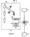
- FIG. 8is a network diagram of an illustrative embodiment of a SIC-MF-MCCE combination system in accordance with our invention.
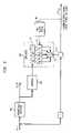
- FIG. 10is a flow diagram illustrating a method of operation for the PIC-MCCE combination of FIG. 9 .
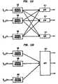
- FIG. 14is a network diagram of an illustrative embodiment of a J-STAPSIC combination system in accordance with our invention.
- the adaptive technique used for channel estimationis based on minimum cost estimation techniques.
- FIG. 14depicts one illustrative embodiment of our invention. We shall refer to this system as the J-STAPSIC system.
- Each J-STAPSIC stage 1404comprises a plurality of STAP filters 1250 , one per antenna, in a parallel arrangement, a plurality of respread processors 208 , one per previous stage, in a parallel arrangement for receiving the symbol estimates from the previous J-STAPSIC stages 1404 , a plurality of ATRFs 1410 , one per previous stage, a mathematical summation circuit 1414 for summing the outputs of the plurality of STAP filters 1250 , a mathematical summation circuit 1414 for summing the outputs of the plurality of ATRFs 1410 , a mathematical operations processor 212 for adding the outputs of the mathematical summation circuits 1414 , a conventional detector 206 , and a respread processor 208 .
Landscapes
- Engineering & Computer Science (AREA)
- Computer Networks & Wireless Communication (AREA)
- Signal Processing (AREA)
- Noise Elimination (AREA)
Abstract
Description
this is expressed in vector form as:
rl(j)=rl−wHBlH
where rlis the vector of received signals at time index I, and samples of the reconstructed waveform are contained in the vector:
ŝk,n=[ŝk(nTs)ŝk((n+1)Ts) . . .ŝk((n+Q−1)Ts)]
J(w)=|rl(j)|2=|rl−wHBlH|2
which simultaneously minimizes both the residual at the output of the jthstage of the SIC receiver and the difference between the ATRF filter output and the received data rl. The solution to this problem is obtained using standard techniques, where we obtain:
w=(BlHBl)BlHrlH
r1represents a row vector containing the Q samples of the received signal, r(nTs) through r((n+Q−1)Ts). Then at stage j, the cleaned signal is:
r1(j)=r1−wHB1
- where
Using these equations, the
J(w)=∥r1−wHB1∥2
which gives:
w=(BlB1H)−1Blr1H
The
Claims (12)
Priority Applications (1)
| Application Number | Priority Date | Filing Date | Title |
|---|---|---|---|
| US10/971,233US7688777B2 (en) | 2000-03-21 | 2005-01-31 | Combined adaptive spatio-temporal processing and multi-user detection for CDMA wireless systems |
Applications Claiming Priority (3)
| Application Number | Priority Date | Filing Date | Title |
|---|---|---|---|
| US19080300P | 2000-03-21 | 2000-03-21 | |
| US09/813,491US20030206577A1 (en) | 2000-03-21 | 2001-03-21 | Combined adaptive spatio-temporal processing and multi-user detection for CDMA wireless systems |
| US10/971,233US7688777B2 (en) | 2000-03-21 | 2005-01-31 | Combined adaptive spatio-temporal processing and multi-user detection for CDMA wireless systems |
Related Parent Applications (1)
| Application Number | Title | Priority Date | Filing Date |
|---|---|---|---|
| US09/813,491DivisionUS20030206577A1 (en) | 2000-03-21 | 2001-03-21 | Combined adaptive spatio-temporal processing and multi-user detection for CDMA wireless systems |
Publications (2)
| Publication Number | Publication Date |
|---|---|
| US20050128985A1 US20050128985A1 (en) | 2005-06-16 |
| US7688777B2true US7688777B2 (en) | 2010-03-30 |
Family
ID=22702845
Family Applications (4)
| Application Number | Title | Priority Date | Filing Date |
|---|---|---|---|
| US09/813,491AbandonedUS20030206577A1 (en) | 2000-03-21 | 2001-03-21 | Combined adaptive spatio-temporal processing and multi-user detection for CDMA wireless systems |
| US10/971,237Active2026-12-24US8111669B2 (en) | 2000-03-21 | 2005-01-27 | Parallel interference cancellation and minimum cost channel estimation |
| US10/971,233Expired - LifetimeUS7688777B2 (en) | 2000-03-21 | 2005-01-31 | Combined adaptive spatio-temporal processing and multi-user detection for CDMA wireless systems |
| US13/365,757Expired - Fee RelatedUS8670418B2 (en) | 2000-03-21 | 2012-02-03 | Successive interference cancellation |
Family Applications Before (2)
| Application Number | Title | Priority Date | Filing Date |
|---|---|---|---|
| US09/813,491AbandonedUS20030206577A1 (en) | 2000-03-21 | 2001-03-21 | Combined adaptive spatio-temporal processing and multi-user detection for CDMA wireless systems |
| US10/971,237Active2026-12-24US8111669B2 (en) | 2000-03-21 | 2005-01-27 | Parallel interference cancellation and minimum cost channel estimation |
Family Applications After (1)
| Application Number | Title | Priority Date | Filing Date |
|---|---|---|---|
| US13/365,757Expired - Fee RelatedUS8670418B2 (en) | 2000-03-21 | 2012-02-03 | Successive interference cancellation |
Country Status (3)
| Country | Link |
|---|---|
| US (4) | US20030206577A1 (en) |
| AU (1) | AU2001250925A1 (en) |
| WO (1) | WO2001071927A2 (en) |
Cited By (14)
| Publication number | Priority date | Publication date | Assignee | Title |
|---|---|---|---|---|
| US20090247086A1 (en)* | 2008-03-31 | 2009-10-01 | Xintian Eddie Lin | Reducing co-channel interference |
| US20090279442A1 (en)* | 2008-05-09 | 2009-11-12 | Vodafone Holding Gmbh | Method and system for data communication |
| US8670418B2 (en) | 2000-03-21 | 2014-03-11 | Tti Inventions C Llc | Successive interference cancellation |
| US8710836B2 (en) | 2008-12-10 | 2014-04-29 | Nanomr, Inc. | NMR, instrumentation, and flow meter/controller continuously detecting MR signals, from continuously flowing sample material |
| US8841104B2 (en) | 2010-04-21 | 2014-09-23 | Nanomr, Inc. | Methods for isolating a target analyte from a heterogeneous sample |
| US9389225B2 (en) | 2010-04-21 | 2016-07-12 | Dna Electronics, Inc. | Separating target analytes using alternating magnetic fields |
| US9428547B2 (en) | 2010-04-21 | 2016-08-30 | Dna Electronics, Inc. | Compositions for isolating a target analyte from a heterogeneous sample |
| US9476812B2 (en) | 2010-04-21 | 2016-10-25 | Dna Electronics, Inc. | Methods for isolating a target analyte from a heterogeneous sample |
| US9551704B2 (en) | 2012-12-19 | 2017-01-24 | Dna Electronics, Inc. | Target detection |
| US9599610B2 (en) | 2012-12-19 | 2017-03-21 | Dnae Group Holdings Limited | Target capture system |
| US9804069B2 (en) | 2012-12-19 | 2017-10-31 | Dnae Group Holdings Limited | Methods for degrading nucleic acid |
| US9902949B2 (en) | 2012-12-19 | 2018-02-27 | Dnae Group Holdings Limited | Methods for universal target capture |
| US9995742B2 (en) | 2012-12-19 | 2018-06-12 | Dnae Group Holdings Limited | Sample entry |
| US10000557B2 (en) | 2012-12-19 | 2018-06-19 | Dnae Group Holdings Limited | Methods for raising antibodies |
Families Citing this family (53)
| Publication number | Priority date | Publication date | Assignee | Title |
|---|---|---|---|---|
| US7783299B2 (en) | 1999-01-08 | 2010-08-24 | Trueposition, Inc. | Advanced triggers for location-based service applications in a wireless location system |
| US6184829B1 (en) | 1999-01-08 | 2001-02-06 | Trueposition, Inc. | Calibration for wireless location system |
| US6765531B2 (en) | 1999-01-08 | 2004-07-20 | Trueposition, Inc. | System and method for interference cancellation in a location calculation, for use in a wireless location system |
| US6711219B2 (en)* | 2000-12-04 | 2004-03-23 | Tensorcomm, Incorporated | Interference cancellation in a signal |
| US7061891B1 (en) | 2001-02-02 | 2006-06-13 | Science Applications International Corporation | Method and system for a remote downlink transmitter for increasing the capacity and downlink capability of a multiple access interference limited spread-spectrum wireless network |
| US7376175B2 (en)* | 2001-03-14 | 2008-05-20 | Mercury Computer Systems, Inc. | Wireless communications systems and methods for cache enabled multiple processor based multiple user detection |
| US7110437B2 (en) | 2001-03-14 | 2006-09-19 | Mercury Computer Systems, Inc. | Wireless communications systems and methods for direct memory access and buffering of digital signals for multiple user detection |
| US7209515B2 (en)* | 2001-03-30 | 2007-04-24 | Science Applications International Corporation | Multistage reception of code division multiple access transmissions |
| SE0101175D0 (en)* | 2001-04-02 | 2001-04-02 | Coding Technologies Sweden Ab | Aliasing reduction using complex-exponential-modulated filter banks |
| CN100586118C (en)* | 2001-08-21 | 2010-01-27 | 英芬能技术公司 | Method and apparatus for increasing data rate in spread spectrum communication system |
| US7006461B2 (en)* | 2001-09-17 | 2006-02-28 | Science Applications International Corporation | Method and system for a channel selective repeater with capacity enhancement in a spread-spectrum wireless network |
| US7130662B2 (en)* | 2002-08-01 | 2006-10-31 | Interdigital Technology Corporation | Simple smart-antenna system for MUD-enabled cellular networks |
| US7260161B2 (en)* | 2002-12-24 | 2007-08-21 | Electronics And Telecommunications Research Institute | Hybrid multi-user interference cancellation method and device using clustering algorithm based on dynamic programming |
| US20050175074A1 (en)* | 2004-02-11 | 2005-08-11 | Interdigital Technology Corporation | Wireless communication method and apparatus for performing multi-user detection using reduced length channel impulse responses |
| US7724851B2 (en)* | 2004-03-04 | 2010-05-25 | Bae Systems Information And Electronic Systems Integration Inc. | Receiver with multiple collectors in a multiple user detection system |
| US7339980B2 (en)* | 2004-03-05 | 2008-03-04 | Telefonaktiebolaget Lm Ericsson (Publ) | Successive interference cancellation in a generalized RAKE receiver architecture |
| US7398078B2 (en)* | 2004-03-05 | 2008-07-08 | Seknion, Inc. | Method and apparatus for security in a wireless network |
| US7456726B2 (en)* | 2004-03-05 | 2008-11-25 | Seknion, Inc. | Method and apparatus for improving the efficiency and accuracy of RFID systems |
| US7536158B2 (en) | 2004-03-29 | 2009-05-19 | Telefonaktiebolaget Lm Ericsson (Publ) | Impairment correlation estimation in a spread spectrum system |
| US7602835B1 (en)* | 2004-08-10 | 2009-10-13 | L-3 Communications Corporation | Multi-rate spread spectrum composite code |
| US8098776B2 (en)* | 2004-10-06 | 2012-01-17 | Broadcom Corporation | Method and system for pre-equalization in a single weight spatial multiplexing MIMO system |
| US8111789B2 (en) | 2004-10-06 | 2012-02-07 | Broadcom Corporation | Method and system for channel estimation in a single channel MIMO system with multiple RF chains for WCDMA/HSDPA |
| US7801248B2 (en)* | 2004-11-19 | 2010-09-21 | Qualcomm Incorporated | Interference suppression with virtual antennas |
| WO2006073893A2 (en)* | 2005-01-05 | 2006-07-13 | Atc Technologies, Llc | Adaptive beam forming with multi-user detection and interference reduction in satellite communiation systems and methods |
| FR2887379B1 (en)* | 2005-06-17 | 2007-08-31 | Thales Sa | METHOD FOR BLINDLY DEMODULATING UPPER ORDERS OF SEVERAL LINEAR WAVEFORM TRANSMITTERS |
| US8855704B2 (en) | 2005-08-26 | 2014-10-07 | Qualcomm Incorporated | Fast cell selection in TD-CDMA (UMTS TDD) |
| US8130727B2 (en)* | 2005-10-27 | 2012-03-06 | Qualcomm Incorporated | Quasi-orthogonal allocation of codes in TD-CDMA systems |
| US8068464B2 (en) | 2005-10-27 | 2011-11-29 | Qualcomm Incorporated | Varying scrambling/OVSF codes within a TD-CDMA slot to overcome jamming effect by a dominant interferer |
| KR101393450B1 (en) | 2006-01-12 | 2014-05-13 | 에이저 시스템즈 엘엘시 | Receiver employing non-pilot reference channels for equalizing a received signal |
| US7924930B1 (en)* | 2006-02-15 | 2011-04-12 | Marvell International Ltd. | Robust synchronization and detection mechanisms for OFDM WLAN systems |
| US8275323B1 (en) | 2006-07-14 | 2012-09-25 | Marvell International Ltd. | Clear-channel assessment in 40 MHz wireless receivers |
| US20080069197A1 (en)* | 2006-09-20 | 2008-03-20 | Agere Systems Inc. | Equalizer for equalizing multiple received versions of a signal |
| US8737451B2 (en)* | 2007-03-09 | 2014-05-27 | Qualcomm Incorporated | MMSE MUD in 1x mobiles |
| FR2927748B1 (en)* | 2008-02-19 | 2015-10-16 | Thales Sa | METHOD OF PROCESSING A FIRST AND A SECOND SIGNAL OVERLOADED WITHIN A INCIDENT COMPOSITE SIGNAL, AND CORRESPONDING DEVICE |
| FR2930389B1 (en)* | 2008-04-22 | 2012-08-10 | Thales Sa | PROCESS FOR PROCESSING A FIRST AND A SECOND SIGNAL OVERLAPPED WITHIN A INCIDENT COMPOSITE SIGNAL AND CORRESPONDING DEVICE THEREFOR. |
| WO2010128413A1 (en)* | 2009-05-07 | 2010-11-11 | Koninklijke Philips Electronics, N.V. | System and method for generating a tomographic reconstruction filter |
| CA2693012C (en)* | 2009-09-18 | 2015-06-23 | Her Majesty The Queen In Right Of Canada As Represented By The Ministeof National Defence | Signal detection in fading environments |
| US8428629B2 (en)* | 2010-03-31 | 2013-04-23 | Qualcomm Incorporated | Methods and apparatus for determining a communications mode and/or using a determined communications mode |
| JP5679771B2 (en)* | 2010-11-01 | 2015-03-04 | 株式会社Nttドコモ | Wireless communication apparatus and wireless communication method |
| KR101588712B1 (en) | 2010-11-16 | 2016-01-26 | 삼성전자주식회사 | Method and apparatus of controlling inter cell interference based on cooperation of intra cell terminals |
| CN102611648B (en)* | 2011-01-20 | 2015-04-01 | 中兴通讯股份有限公司 | Successive interference cancellation system and method |
| US9209858B2 (en)* | 2011-04-12 | 2015-12-08 | Alcatel Lucent | Method and apparatus for determining uplink noise power in a wireless communication system |
| US8767799B2 (en) | 2011-04-12 | 2014-07-01 | Alcatel Lucent | Method and apparatus for determining signal-to-noise ratio |
| US8982849B1 (en) | 2011-12-15 | 2015-03-17 | Marvell International Ltd. | Coexistence mechanism for 802.11AC compliant 80 MHz WLAN receivers |
| WO2015008165A2 (en)* | 2013-06-25 | 2015-01-22 | Nguyen Thuy Duong | Detection of weak user signal in double transmission |
| CN103731383B (en)* | 2013-12-18 | 2017-07-21 | 华为技术有限公司 | A kind of interference elimination method and device, receiver |
| US20160036490A1 (en)* | 2014-08-01 | 2016-02-04 | Futurewei Technologies, Inc. | Interference Cancellation in Coaxial Cable Connected Data Over Cable Service Interface Specification (DOCSIS) System or Cable Network |
| US9885772B1 (en) | 2014-08-26 | 2018-02-06 | Vencore Labs, Inc. | Geolocating wireless emitters |
| US10051616B2 (en)* | 2014-10-07 | 2018-08-14 | Massachusetts Institute Of Technology | Multiuser detection for high capacity cellular downlink |
| US9602240B1 (en)* | 2015-09-11 | 2017-03-21 | Signalchip Innovations Private Limited | Method and system for symbol level interference cancellation at a receiver for multiuser detection |
| WO2017101097A1 (en)* | 2015-12-18 | 2017-06-22 | 华为技术有限公司 | Channel statistical information obtaining method and receiver |
| US10855327B2 (en) | 2019-03-01 | 2020-12-01 | Huawei Technologies Co., Ltd. | Parallelized successive interference cancellation (PSiC) receiver architecture for wireless communications systems |
| CN119727943A (en)* | 2024-11-01 | 2025-03-28 | 北京理工大学 | Multi-user non-orthogonal signal acquisition method based on interference removal correlation peak difference |
Citations (23)
| Publication number | Priority date | Publication date | Assignee | Title |
|---|---|---|---|---|
| US5170411A (en) | 1990-09-21 | 1992-12-08 | Victor Company Of Japan, Ltd. | Modulation and demodulation system for spread spectrum transmission |
| US5268927A (en)* | 1992-10-06 | 1993-12-07 | Mayflower Communications Company, Inc. | Digital adaptive transversal filter for spread spectrum receivers |
| US5596600A (en) | 1995-04-06 | 1997-01-21 | Mayflower Communications Company, Inc. | Standalone canceller of narrow band interference for spread spectrum receivers |
| US5598428A (en)* | 1993-12-16 | 1997-01-28 | Nec Corporation | DS/CDMA diversity receiver with despreading filters using combiner wherein first and second despreading filters are delayed with respect to each other by a period of half the chip rate |
| US5719899A (en)* | 1994-02-25 | 1998-02-17 | U.S. Philips Corporation | Multiple access digital transmission system and a radio base station and a receiver for use in such a system |
| US5757845A (en)* | 1994-02-10 | 1998-05-26 | Ntt Mobile Communications Network | Adaptive spread spectrum receiver |
| US5818882A (en) | 1995-01-31 | 1998-10-06 | Nec Corporation | Frequency offset cancellation apparatus |
| US5859870A (en)* | 1995-10-23 | 1999-01-12 | Nec Corporation | Time diversity transmission-reception system |
| US5872540A (en) | 1997-06-26 | 1999-02-16 | Electro-Radiation Incorporated | Digital interference suppression system for radio frequency interference cancellation |
| US6115409A (en)* | 1999-06-21 | 2000-09-05 | Envoy Networks, Inc. | Integrated adaptive spatial-temporal system for controlling narrowband and wideband sources of interferences in spread spectrum CDMA receivers |
| US6137788A (en)* | 1995-06-13 | 2000-10-24 | Ntt Mobile Communications Network, Inc. | CDMA demodulating apparatus |
| US6144711A (en)* | 1996-08-29 | 2000-11-07 | Cisco Systems, Inc. | Spatio-temporal processing for communication |
| US6275543B1 (en)* | 1996-10-11 | 2001-08-14 | Arraycomm, Inc. | Method for reference signal generation in the presence of frequency offsets in a communications station with spatial processing |
| US6301293B1 (en)* | 1998-08-04 | 2001-10-09 | Agere Systems Guardian Corp. | Detectors for CDMA systems |
| US6331837B1 (en)* | 1997-05-23 | 2001-12-18 | Genghiscomm Llc | Spatial interferometry multiplexing in wireless communications |
| US6363104B1 (en)* | 1998-10-02 | 2002-03-26 | Ericsson Inc. | Method and apparatus for interference cancellation in a rake receiver |
| US6393073B1 (en)* | 1999-06-28 | 2002-05-21 | Raytheon Company | Method of frequency offset estimation and correction for adaptive antennas |
| US6456647B1 (en)* | 1998-12-16 | 2002-09-24 | Lsi Logic Corporation | Two step signal recovery scheme for a receiver |
| US6570918B1 (en) | 1998-08-19 | 2003-05-27 | Siemens Aktiengesellschaft | Receiver and method for recovering data from spread spectrum radio signals |
| US6618433B1 (en)* | 2000-08-04 | 2003-09-09 | Intel Corporation | Family of linear multi-user detectors (MUDs) |
| US6721293B1 (en)* | 1999-03-10 | 2004-04-13 | Nokia Corporation | Unsupervised adaptive chip separation filter for CDMA terminal |
| US6768747B1 (en)* | 2000-11-30 | 2004-07-27 | Arraycomm, Inc. | Relative and absolute timing acquisition for a radio communications system |
| US6782036B1 (en)* | 1999-05-26 | 2004-08-24 | Board Of Regents, The University Of Texas System | Smart antenna multiuser detector |
Family Cites Families (11)
| Publication number | Priority date | Publication date | Assignee | Title |
|---|---|---|---|---|
| US5218619A (en)* | 1990-12-17 | 1993-06-08 | Ericsson Ge Mobile Communications Holding, Inc. | CDMA subtractive demodulation |
| EP0700156B1 (en)* | 1994-09-01 | 2002-06-05 | Nec Corporation | Beamformer using coefficient restrained adaptive filters for cancelling interference signals |
| KR100204599B1 (en)* | 1996-12-21 | 1999-06-15 | 정선종 | Adaptive and mixed noise eliminating method |
| JPH11251959A (en)* | 1998-03-05 | 1999-09-17 | Fujitsu Ltd | Interference canceller device and wireless communication device |
| US6363103B1 (en)* | 1998-04-09 | 2002-03-26 | Lucent Technologies Inc. | Multistage interference cancellation for CDMA applications using M-ary orthogonal moduation |
| JP3800382B2 (en)* | 1998-09-04 | 2006-07-26 | 富士通株式会社 | Propagation path estimation method and interference canceller in interference canceller |
| JP3121319B2 (en)* | 1998-12-17 | 2000-12-25 | 日本電気株式会社 | DS-CDMA multi-user interference canceller and its system |
| US6700923B1 (en)* | 1999-01-04 | 2004-03-02 | Board Of Regents The University Of Texas System | Adaptive multiple access interference suppression |
| US6252540B1 (en)* | 1999-12-21 | 2001-06-26 | The United States Of America As Represented By The Secretary Of The Air Force | Apparatus and method for two stage hybrid space-time adaptive processing in radar and communication systems |
| US6975666B2 (en)* | 1999-12-23 | 2005-12-13 | Institut National De La Recherche Scientifique | Interference suppression in CDMA systems |
| US20030206577A1 (en) | 2000-03-21 | 2003-11-06 | Liberti Joseph Charles | Combined adaptive spatio-temporal processing and multi-user detection for CDMA wireless systems |
- 2001
- 2001-03-21USUS09/813,491patent/US20030206577A1/ennot_activeAbandoned
- 2001-03-21WOPCT/US2001/009157patent/WO2001071927A2/enactiveApplication Filing
- 2001-03-21AUAU2001250925Apatent/AU2001250925A1/ennot_activeAbandoned
- 2005
- 2005-01-27USUS10/971,237patent/US8111669B2/enactiveActive
- 2005-01-31USUS10/971,233patent/US7688777B2/ennot_activeExpired - Lifetime
- 2012
- 2012-02-03USUS13/365,757patent/US8670418B2/ennot_activeExpired - Fee Related
Patent Citations (23)
| Publication number | Priority date | Publication date | Assignee | Title |
|---|---|---|---|---|
| US5170411A (en) | 1990-09-21 | 1992-12-08 | Victor Company Of Japan, Ltd. | Modulation and demodulation system for spread spectrum transmission |
| US5268927A (en)* | 1992-10-06 | 1993-12-07 | Mayflower Communications Company, Inc. | Digital adaptive transversal filter for spread spectrum receivers |
| US5598428A (en)* | 1993-12-16 | 1997-01-28 | Nec Corporation | DS/CDMA diversity receiver with despreading filters using combiner wherein first and second despreading filters are delayed with respect to each other by a period of half the chip rate |
| US5757845A (en)* | 1994-02-10 | 1998-05-26 | Ntt Mobile Communications Network | Adaptive spread spectrum receiver |
| US5719899A (en)* | 1994-02-25 | 1998-02-17 | U.S. Philips Corporation | Multiple access digital transmission system and a radio base station and a receiver for use in such a system |
| US5818882A (en) | 1995-01-31 | 1998-10-06 | Nec Corporation | Frequency offset cancellation apparatus |
| US5596600A (en) | 1995-04-06 | 1997-01-21 | Mayflower Communications Company, Inc. | Standalone canceller of narrow band interference for spread spectrum receivers |
| US6137788A (en)* | 1995-06-13 | 2000-10-24 | Ntt Mobile Communications Network, Inc. | CDMA demodulating apparatus |
| US5859870A (en)* | 1995-10-23 | 1999-01-12 | Nec Corporation | Time diversity transmission-reception system |
| US6144711A (en)* | 1996-08-29 | 2000-11-07 | Cisco Systems, Inc. | Spatio-temporal processing for communication |
| US6275543B1 (en)* | 1996-10-11 | 2001-08-14 | Arraycomm, Inc. | Method for reference signal generation in the presence of frequency offsets in a communications station with spatial processing |
| US6331837B1 (en)* | 1997-05-23 | 2001-12-18 | Genghiscomm Llc | Spatial interferometry multiplexing in wireless communications |
| US5872540A (en) | 1997-06-26 | 1999-02-16 | Electro-Radiation Incorporated | Digital interference suppression system for radio frequency interference cancellation |
| US6301293B1 (en)* | 1998-08-04 | 2001-10-09 | Agere Systems Guardian Corp. | Detectors for CDMA systems |
| US6570918B1 (en) | 1998-08-19 | 2003-05-27 | Siemens Aktiengesellschaft | Receiver and method for recovering data from spread spectrum radio signals |
| US6363104B1 (en)* | 1998-10-02 | 2002-03-26 | Ericsson Inc. | Method and apparatus for interference cancellation in a rake receiver |
| US6456647B1 (en)* | 1998-12-16 | 2002-09-24 | Lsi Logic Corporation | Two step signal recovery scheme for a receiver |
| US6721293B1 (en)* | 1999-03-10 | 2004-04-13 | Nokia Corporation | Unsupervised adaptive chip separation filter for CDMA terminal |
| US6782036B1 (en)* | 1999-05-26 | 2004-08-24 | Board Of Regents, The University Of Texas System | Smart antenna multiuser detector |
| US6115409A (en)* | 1999-06-21 | 2000-09-05 | Envoy Networks, Inc. | Integrated adaptive spatial-temporal system for controlling narrowband and wideband sources of interferences in spread spectrum CDMA receivers |
| US6393073B1 (en)* | 1999-06-28 | 2002-05-21 | Raytheon Company | Method of frequency offset estimation and correction for adaptive antennas |
| US6618433B1 (en)* | 2000-08-04 | 2003-09-09 | Intel Corporation | Family of linear multi-user detectors (MUDs) |
| US6768747B1 (en)* | 2000-11-30 | 2004-07-27 | Arraycomm, Inc. | Relative and absolute timing acquisition for a radio communications system |
Non-Patent Citations (4)
| Title |
|---|
| Moshavi, Combined space time adaptive processing, 2000 IEEE Sixth international symposium, V 2, Sept. 6-8, 2000, pp. 449-454.* |
| Moshavi, Shimon. "Multi-User Detection for DS-CDMA Communications". IEEE Communications Magazine. Oct. 1996. pp. 124-136. |
| Park, Sheeyun; Sarkar, Tapan K. "A Blind Least-Squares Approach to STAP using MCARM Data". IEEE Signals, Systems & Computers. Nov. 1998. pp. 1552-1556. |
| Sam, Phirin; USPTO Box PCT; "International Search Report" dated Aug. 21, 2001. 3 pgs. |
Cited By (29)
| Publication number | Priority date | Publication date | Assignee | Title |
|---|---|---|---|---|
| US8670418B2 (en) | 2000-03-21 | 2014-03-11 | Tti Inventions C Llc | Successive interference cancellation |
| US20090247086A1 (en)* | 2008-03-31 | 2009-10-01 | Xintian Eddie Lin | Reducing co-channel interference |
| US8521089B2 (en)* | 2008-03-31 | 2013-08-27 | Intel Corporation | Reducing co-channel interference |
| US20090279442A1 (en)* | 2008-05-09 | 2009-11-12 | Vodafone Holding Gmbh | Method and system for data communication |
| US8412260B2 (en)* | 2008-05-09 | 2013-04-02 | Vodafone Holding Gmbh | Method and system for data communication |
| US8710836B2 (en) | 2008-12-10 | 2014-04-29 | Nanomr, Inc. | NMR, instrumentation, and flow meter/controller continuously detecting MR signals, from continuously flowing sample material |
| US9696302B2 (en) | 2010-04-21 | 2017-07-04 | Dnae Group Holdings Limited | Methods for isolating a target analyte from a heterogeneous sample |
| US9970931B2 (en) | 2010-04-21 | 2018-05-15 | Dnae Group Holdings Limited | Methods for isolating a target analyte from a heterogenous sample |
| US9428547B2 (en) | 2010-04-21 | 2016-08-30 | Dna Electronics, Inc. | Compositions for isolating a target analyte from a heterogeneous sample |
| US9476812B2 (en) | 2010-04-21 | 2016-10-25 | Dna Electronics, Inc. | Methods for isolating a target analyte from a heterogeneous sample |
| US11448646B2 (en) | 2010-04-21 | 2022-09-20 | Dnae Group Holdings Limited | Isolating a target analyte from a body fluid |
| US9562896B2 (en) | 2010-04-21 | 2017-02-07 | Dnae Group Holdings Limited | Extracting low concentrations of bacteria from a sample |
| US11073513B2 (en) | 2010-04-21 | 2021-07-27 | Dnae Group Holdings Limited | Separating target analytes using alternating magnetic fields |
| US9671395B2 (en) | 2010-04-21 | 2017-06-06 | Dnae Group Holdings Limited | Analyzing bacteria without culturing |
| US8841104B2 (en) | 2010-04-21 | 2014-09-23 | Nanomr, Inc. | Methods for isolating a target analyte from a heterogeneous sample |
| US10677789B2 (en) | 2010-04-21 | 2020-06-09 | Dnae Group Holdings Limited | Analyzing bacteria without culturing |
| US9869671B2 (en) | 2010-04-21 | 2018-01-16 | Dnae Group Holdings Limited | Analyzing bacteria without culturing |
| US9389225B2 (en) | 2010-04-21 | 2016-07-12 | Dna Electronics, Inc. | Separating target analytes using alternating magnetic fields |
| US9902949B2 (en) | 2012-12-19 | 2018-02-27 | Dnae Group Holdings Limited | Methods for universal target capture |
| US9995742B2 (en) | 2012-12-19 | 2018-06-12 | Dnae Group Holdings Limited | Sample entry |
| US10000557B2 (en) | 2012-12-19 | 2018-06-19 | Dnae Group Holdings Limited | Methods for raising antibodies |
| US10379113B2 (en) | 2012-12-19 | 2019-08-13 | Dnae Group Holdings Limited | Target detection |
| US10584329B2 (en) | 2012-12-19 | 2020-03-10 | Dnae Group Holdings Limited | Methods for universal target capture |
| US9804069B2 (en) | 2012-12-19 | 2017-10-31 | Dnae Group Holdings Limited | Methods for degrading nucleic acid |
| US10745763B2 (en) | 2012-12-19 | 2020-08-18 | Dnae Group Holdings Limited | Target capture system |
| US11016086B2 (en) | 2012-12-19 | 2021-05-25 | Dnae Group Holdings Limited | Sample entry |
| US9599610B2 (en) | 2012-12-19 | 2017-03-21 | Dnae Group Holdings Limited | Target capture system |
| US9551704B2 (en) | 2012-12-19 | 2017-01-24 | Dna Electronics, Inc. | Target detection |
| US11603400B2 (en) | 2012-12-19 | 2023-03-14 | Dnae Group Holdings Limited | Methods for raising antibodies |
Also Published As
| Publication number | Publication date |
|---|---|
| WO2001071927A3 (en) | 2002-02-28 |
| US20050111414A1 (en) | 2005-05-26 |
| US8670418B2 (en) | 2014-03-11 |
| US20120201279A1 (en) | 2012-08-09 |
| US20050128985A1 (en) | 2005-06-16 |
| WO2001071927A2 (en) | 2001-09-27 |
| US20030206577A1 (en) | 2003-11-06 |
| AU2001250925A1 (en) | 2001-10-03 |
| US8111669B2 (en) | 2012-02-07 |
Similar Documents
| Publication | Publication Date | Title |
|---|---|---|
| US7688777B2 (en) | Combined adaptive spatio-temporal processing and multi-user detection for CDMA wireless systems | |
| JP4263368B2 (en) | Apparatus and method for interference cancellation in spread spectrum communications | |
| JP3202754B2 (en) | How to handle multiple multiple access transmissions | |
| US6301293B1 (en) | Detectors for CDMA systems | |
| US6801565B1 (en) | Multi-stage rake combining methods and apparatus | |
| KR100383208B1 (en) | Method and System for Demodulation of Downlink CDMA Signals | |
| US7339980B2 (en) | Successive interference cancellation in a generalized RAKE receiver architecture | |
| US6529545B2 (en) | Rake receiver | |
| US7548580B2 (en) | Adaptive pilot interference cancellation in CDMA systems | |
| US6700923B1 (en) | Adaptive multiple access interference suppression | |
| US6501747B1 (en) | Manifold assisted channel estimation and demodulation for CDMA systems in fast fading environments | |
| US6721293B1 (en) | Unsupervised adaptive chip separation filter for CDMA terminal | |
| US6449266B1 (en) | Data transmission method, transmitter, and receiver | |
| JP2002064467A (en) | Method and device for cancelling multiple access interference in code division multiple access(cdma) communication system | |
| US6385185B1 (en) | Methods and apparatus for coherent detection of signals with orthogonal data modulation | |
| US7599426B2 (en) | Use of adaptive filters in multiple access wireless systems employing predictable signals | |
| US20070189362A1 (en) | Method and system for channel estimation, related receiver and computer program product | |
| US6324160B1 (en) | Adaptive receiver for CDMA base stations | |
| GB2411546A (en) | Interference cancellation in CDMA system | |
| US6667964B1 (en) | Propagation path-estimation method for an interference canceler and interference elimination apparatus | |
| EP0674401B1 (en) | Spread spectrum signal receiver | |
| EP0988706B1 (en) | Reception method and receiver | |
| US7184465B2 (en) | Signal processing method and apparatus for a spread spectrum radio communication receiver | |
| Shakya et al. | High user capacity collaborative code-division multiple access | |
| US7756191B2 (en) | Deconvolution searcher for wireless communication system |
Legal Events
| Date | Code | Title | Description |
|---|---|---|---|
| AS | Assignment | Owner name:JPMORGAN CHASE BANK, N.A., AS ADMINISTRATIVE AGENT Free format text:SECURITY AGREEMENT;ASSIGNOR:TELCORDIA TECHNOLOGIES, INC.;REEL/FRAME:015886/0001 Effective date:20050315 | |
| AS | Assignment | Owner name:TELCORDIA TECHNOLOGIES, INC., NEW JERSEY Free format text:TERMINATION AND RELEASE OF SECURITY INTEREST IN PATENT RIGHTS;ASSIGNOR:JPMORGAN CHASE BANK, N.A., AS ADMINISTRATIVE AGENT;REEL/FRAME:019520/0174 Effective date:20070629 Owner name:TELCORDIA TECHNOLOGIES, INC.,NEW JERSEY Free format text:TERMINATION AND RELEASE OF SECURITY INTEREST IN PATENT RIGHTS;ASSIGNOR:JPMORGAN CHASE BANK, N.A., AS ADMINISTRATIVE AGENT;REEL/FRAME:019520/0174 Effective date:20070629 | |
| AS | Assignment | Owner name:WILMINGTON TRUST COMPANY, AS COLLATERAL AGENT, DEL Free format text:SECURITY AGREEMENT;ASSIGNOR:TELCORDIA TECHNOLOGIES, INC.;REEL/FRAME:019562/0309 Effective date:20070629 Owner name:WILMINGTON TRUST COMPANY, AS COLLATERAL AGENT,DELA Free format text:SECURITY AGREEMENT;ASSIGNOR:TELCORDIA TECHNOLOGIES, INC.;REEL/FRAME:019562/0309 Effective date:20070629 | |
| AS | Assignment | Owner name:TELCORDIA TECHNOLOGIES, INC, NEW JERSEY Free format text:ASSIGNMENT OF ASSIGNORS INTEREST;ASSIGNORS:LIBERTI JR., JOSEPH CHARLES;MOSHAVI, SHIMON;ZABLOCKY, PAUL GERALD;REEL/FRAME:022303/0559;SIGNING DATES FROM 20010501 TO 20010508 Owner name:TELCORDIA TECHNOLOGIES, INC,NEW JERSEY Free format text:ASSIGNMENT OF ASSIGNORS INTEREST;ASSIGNORS:LIBERTI JR., JOSEPH CHARLES;MOSHAVI, SHIMON;ZABLOCKY, PAUL GERALD;SIGNING DATES FROM 20010501 TO 20010508;REEL/FRAME:022303/0559 | |
| AS | Assignment | Owner name:TELCORDIA TECHNOLOGIES, INC., NEW JERSEY Free format text:RELEASE OF SECURITY INTEREST;ASSIGNOR:WILMINGTON TRUST COMPANY;REEL/FRAME:022408/0410 Effective date:20090220 Owner name:TELCORDIA TECHNOLOGIES, INC.,NEW JERSEY Free format text:RELEASE OF SECURITY INTEREST;ASSIGNOR:WILMINGTON TRUST COMPANY;REEL/FRAME:022408/0410 Effective date:20090220 | |
| AS | Assignment | Owner name:TELCORDIA LICENSING COMPANY, LLC, NEW JERSEY Free format text:ASSIGNMENT OF ASSIGNORS INTEREST;ASSIGNOR:TELCORDIA TECHNOLOGIES, INC.;REEL/FRAME:022871/0920 Effective date:20090616 Owner name:TELCORDIA LICENSING COMPANY, LLC,NEW JERSEY Free format text:ASSIGNMENT OF ASSIGNORS INTEREST;ASSIGNOR:TELCORDIA TECHNOLOGIES, INC.;REEL/FRAME:022871/0920 Effective date:20090616 | |
| STCF | Information on status: patent grant | Free format text:PATENTED CASE | |
| AS | Assignment | Owner name:TELCORDIA TECHNOLOGIES, INC.,NEW JERSEY Free format text:RELEASE;ASSIGNOR:WILMINGTON TRUST COMPANY, AS COLLATERAL AGENT;REEL/FRAME:024515/0622 Effective date:20100430 Owner name:TELCORDIA TECHNOLOGIES, INC., NEW JERSEY Free format text:RELEASE;ASSIGNOR:WILMINGTON TRUST COMPANY, AS COLLATERAL AGENT;REEL/FRAME:024515/0622 Effective date:20100430 | |
| CC | Certificate of correction | ||
| AS | Assignment | Owner name:TTI INVENTIONS C LLC, DELAWARE Free format text:ASSIGNMENT OF ASSIGNORS INTEREST;ASSIGNOR:TELCORDIA LICENSING COMPANY LLC;REEL/FRAME:027678/0854 Effective date:20111102 | |
| FPAY | Fee payment | Year of fee payment:4 | |
| AS | Assignment | Owner name:NYTELL SOFTWARE LLC, DELAWARE Free format text:MERGER;ASSIGNOR:TTI INVENTIONS C LLC;REEL/FRAME:036703/0191 Effective date:20150826 | |
| MAFP | Maintenance fee payment | Free format text:PAYMENT OF MAINTENANCE FEE, 8TH YEAR, LARGE ENTITY (ORIGINAL EVENT CODE: M1552) Year of fee payment:8 | |
| MAFP | Maintenance fee payment | Free format text:PAYMENT OF MAINTENANCE FEE, 12TH YEAR, LARGE ENTITY (ORIGINAL EVENT CODE: M1553); ENTITY STATUS OF PATENT OWNER: LARGE ENTITY Year of fee payment:12 |