US7688453B2 - Interferometry testing of lenses, and systems and devices for same - Google Patents
Interferometry testing of lenses, and systems and devices for sameDownload PDFInfo
- Publication number
- US7688453B2 US7688453B2US11/962,555US96255507AUS7688453B2US 7688453 B2US7688453 B2US 7688453B2US 96255507 AUS96255507 AUS 96255507AUS 7688453 B2US7688453 B2US 7688453B2
- Authority
- US
- United States
- Prior art keywords
- lens
- light
- detector
- accordance
- camera
- Prior art date
- Legal status (The legal status is an assumption and is not a legal conclusion. Google has not performed a legal analysis and makes no representation as to the accuracy of the status listed.)
- Active, expires
Links
Images


Classifications
- G—PHYSICS
- G01—MEASURING; TESTING
- G01B—MEASURING LENGTH, THICKNESS OR SIMILAR LINEAR DIMENSIONS; MEASURING ANGLES; MEASURING AREAS; MEASURING IRREGULARITIES OF SURFACES OR CONTOURS
- G01B9/00—Measuring instruments characterised by the use of optical techniques
- G01B9/02—Interferometers
- G—PHYSICS
- G01—MEASURING; TESTING
- G01N—INVESTIGATING OR ANALYSING MATERIALS BY DETERMINING THEIR CHEMICAL OR PHYSICAL PROPERTIES
- G01N35/00—Automatic analysis not limited to methods or materials provided for in any single one of groups G01N1/00 - G01N33/00; Handling materials therefor
- G01N35/02—Automatic analysis not limited to methods or materials provided for in any single one of groups G01N1/00 - G01N33/00; Handling materials therefor using a plurality of sample containers moved by a conveyor system past one or more treatment or analysis stations
- G01N35/025—Automatic analysis not limited to methods or materials provided for in any single one of groups G01N1/00 - G01N33/00; Handling materials therefor using a plurality of sample containers moved by a conveyor system past one or more treatment or analysis stations having a carousel or turntable for reaction cells or cuvettes
- G—PHYSICS
- G01—MEASURING; TESTING
- G01B—MEASURING LENGTH, THICKNESS OR SIMILAR LINEAR DIMENSIONS; MEASURING ANGLES; MEASURING AREAS; MEASURING IRREGULARITIES OF SURFACES OR CONTOURS
- G01B9/00—Measuring instruments characterised by the use of optical techniques
- G01B9/02—Interferometers
- G01B9/02015—Interferometers characterised by the beam path configuration
- G01B9/02024—Measuring in transmission, i.e. light traverses the object
- G—PHYSICS
- G01—MEASURING; TESTING
- G01B—MEASURING LENGTH, THICKNESS OR SIMILAR LINEAR DIMENSIONS; MEASURING ANGLES; MEASURING AREAS; MEASURING IRREGULARITIES OF SURFACES OR CONTOURS
- G01B9/00—Measuring instruments characterised by the use of optical techniques
- G01B9/02—Interferometers
- G01B9/02041—Interferometers characterised by particular imaging or detection techniques
- G01B9/02048—Rough and fine measurement
- G—PHYSICS
- G01—MEASURING; TESTING
- G01B—MEASURING LENGTH, THICKNESS OR SIMILAR LINEAR DIMENSIONS; MEASURING ANGLES; MEASURING AREAS; MEASURING IRREGULARITIES OF SURFACES OR CONTOURS
- G01B9/00—Measuring instruments characterised by the use of optical techniques
- G01B9/02—Interferometers
- G01B9/02055—Reduction or prevention of errors; Testing; Calibration
- G01B9/0207—Error reduction by correction of the measurement signal based on independently determined error sources, e.g. using a reference interferometer
- G01B9/02072—Error reduction by correction of the measurement signal based on independently determined error sources, e.g. using a reference interferometer by calibration or testing of interferometer
- G—PHYSICS
- G01—MEASURING; TESTING
- G01M—TESTING STATIC OR DYNAMIC BALANCE OF MACHINES OR STRUCTURES; TESTING OF STRUCTURES OR APPARATUS, NOT OTHERWISE PROVIDED FOR
- G01M11/00—Testing of optical apparatus; Testing structures by optical methods not otherwise provided for
- G01M11/02—Testing optical properties
- G01M11/0285—Testing optical properties by measuring material or chromatic transmission properties
- G—PHYSICS
- G01—MEASURING; TESTING
- G01N—INVESTIGATING OR ANALYSING MATERIALS BY DETERMINING THEIR CHEMICAL OR PHYSICAL PROPERTIES
- G01N21/00—Investigating or analysing materials by the use of optical means, i.e. using sub-millimetre waves, infrared, visible or ultraviolet light
- G01N21/01—Arrangements or apparatus for facilitating the optical investigation
- G01N21/03—Cuvette constructions
- G—PHYSICS
- G01—MEASURING; TESTING
- G01N—INVESTIGATING OR ANALYSING MATERIALS BY DETERMINING THEIR CHEMICAL OR PHYSICAL PROPERTIES
- G01N35/00—Automatic analysis not limited to methods or materials provided for in any single one of groups G01N1/00 - G01N33/00; Handling materials therefor
- G01N35/02—Automatic analysis not limited to methods or materials provided for in any single one of groups G01N1/00 - G01N33/00; Handling materials therefor using a plurality of sample containers moved by a conveyor system past one or more treatment or analysis stations
- G—PHYSICS
- G01—MEASURING; TESTING
- G01B—MEASURING LENGTH, THICKNESS OR SIMILAR LINEAR DIMENSIONS; MEASURING ANGLES; MEASURING AREAS; MEASURING IRREGULARITIES OF SURFACES OR CONTOURS
- G01B2290/00—Aspects of interferometers not specifically covered by any group under G01B9/02
- G01B2290/45—Multiple detectors for detecting interferometer signals
Definitions
- the technical fieldrelates generally to optics and more specifically a systems and methods for testing optical lenses, vessels for holding the lenses, and methods for analyzing optical characteristics of the lenses.
- the contact lens industryhas undergone rapid advancements toward higher levels of visual correction. Manufacturers are progressing toward providing contact lenses that are designed to match a patient's refractive correction and fit. By moving beyond standard spherical lenses, manufacturers will be able to provide contact lens wearers with better visual acuity and overall comfort.
- Metrology (measurement) techniques and instrumentation for evaluating lenseshave not kept up with the rapid advancement in lens technology.
- Current metrologysuch as methods based on focimeters and moiré deflectometry, lacks the combination of spatial resolution, high sensitivity, and large dynamic range desired to accurately measure more advanced lenses.
- Current metrology techniquesgenerally are limited to ophthalmic testing of the effective power of a lens and indirect measurements of power by translating a lens until collimation is detected.
- the present inventioninvolves utilization of a modified Mach-Zehnder (MZ) interferometer to analyze the transmitted, aspherical wavefront of an ophthalmic lens.
- MZMach-Zehnder
- the interferometeris capable of analyzing a wide variety of lens types, such as, for example, spherical, toric, bifocal, and multifocal lenses.
- lensesare mounted in a cuvette that circulates fresh saline about the lenses and is positioned in a vertical test arm of the interferometer configuration.
- a technique referred to as reverse raytracingcan be utilized to remove aberrations induced into the wavefront as it is imaged.
- FIG. 1is a diagram depicting an exemplary interferometer configuration for obtaining a wavefront of a lens.
- FIG. 2depicts an image of an exemplary reference wavefront.
- FIG. 3depicts the transmitted optical path difference with unwanted pixels removed from a positive test lens.
- FIG. 4depicts an exemplary image of a test wavefront.
- FIG. 5depicts an estimate of a measured wavefront transmitted through a test lens.
- FIG. 6shows a measured wavefront and a modeled wavefront for a calibration lens.
- FIG. 7depicts a difference wavefront of the difference between the measured wavefront and the modeled wavefront.
- FIG. 8shows a Zernike surface and image thereof.
- FIG. 9shows a localized defect of a tested lens.
- FIG. 10shows a region in which fringes are slightly flattened.
- FIG. 11shows defects indicative of possible stress or other alterations in the periphery of the lens.
- FIG. 12shows plots of spherical aberration versus frequency for four different lenses.
- FIG. 13shows the thickness of toric lenses.
- FIG. 14is a cross-sectional view of the cuvette.
- FIG. 15is an illustration of an expanded cross-sectional view of a portion of the cuvette.
- FIG. 16depicts an exemplary coupling mechanism.
- FIG. 17is a top view of an illustration of a cuvette positioning mechanism.
- FIG. 18is an illustration of positional flags and positional sensors.
- FIG. 19is a diagram of an enclosed cuvette.
- FIG. 20is a flow diagram of an example process for aligning detectors of an interferometer configuration for obtaining a wavefront of a lens.
- FIG. 21depicts an example target lens used in the alignment of detectors.
- the present inventioninvolves obtaining information utilized to evaluate a wide range of ophthalmic lens types by measuring the transmitted wavefront of the lens.
- a Mach-Zehnder interferometeris used with the lenses submersed in saline solution and mounted in a cuvette, or water cell, that circulates fresh saline solution. Testing lenses in a saline solution is believed to mitigate dehydration of the lens, which can change the lens' index of refraction. Removal of induced aberrations can be achieved, for example, by reverse raytracing, wherein the wavefront at the detector is traced back to a location immediately behind the lens. Reverse raytracing facilitates the generation of theoretical wavefronts, which can be used to evaluate performance at the transmitted wavefront level.
- Example type of lenses that can be evaluatedinclude hard contact lenses, hard refractive contact lenses, hard diffractive contact lenses, hard hybrid refractive/diffractive contact lenses, soft contact lenses, soft refractive contact lenses, soft diffractive contact lenses, soft hybrid refractive/diffractive contact lenses, hard contact lenses comprising an active pharmaceutical, soft contact lenses comprising an active pharmaceutical, single vision lenses, toric lenses, bifocal contact lenses, multifocal lenses, cosmetically tinted lenses, freeform lenses, an intraocular lenses, intraocular refractive lenses, an intraocular diffractive lenses, intraocular hybrid refractive/diffractive lenses, accommodating lenses, spectacle lenses, refractive spectacle lenses, diffractive spectacle lenses, and hybrid refractive/diffractive spectacle lenses, composite lenses comprising multiple and embedded materials, photochromic lenses, and molds used in the fabrication of the aforementioned lenses. It is to be understood that example lenses should not be limited to the preceding list of example lenses. Those of skill in the art will readily recognize that other types of lenses
- FIG. 1is a diagram depicting an exemplary interferometer configuration 12 for obtaining a wavefront of a lens.
- the interferometer configuration 12comprises two beam splitters 18 , 24 and four mirrors 20 , 22 , 26 , 40 for steering beams of light through the reference arm 36 and the vertical test arm 30 .
- the cuvette 28is positioned in the vertical test arm 30 , and the lens, or lenses, to be tested are placed in the cuvette 28 (lens not shown in FIG. 1 ).
- the light source 14such as a laser for example, produces a coherent beam of light. Coherence is measured in units of length, and in an exemplary embodiment, the coherence of the source 14 is greater than the expected difference in optical path distance of the reference arm 36 path and the vertical test arm 30 path.
- Light leaving the source 14is filtered and shaped using a collimating lens 16 .
- the collimated beam of light emanating from the collimating lens 16is split into two beams using a beam splitter 18 at 45°.
- a beam splitteris a special type of mirror wherein 50% of the light is reflected, and the other 50% is transmitted.
- 50% of the collimated light beam emanating from the collimating lens 16is directed, via the beam splitter 18 , toward the mirror 40 and the other 50% of the collimated light beam is directed toward the mirror 20 .
- the beam directed toward the mirror 20is reflected by that mirror through the reference arm 36 .
- This beamis referred to as the reference beam.
- the beam directed toward the mirror 40is also reflected by the mirror 20 through the vertical test arm 30 .
- This beamis referred to as the test beam.
- the test beampasses through the cuvette 28 and test lens contained therein.
- the reference beampasses through air, or any appropriate gas, of the reference arm 36 .
- the reference beam and test beamare recombined, and interference between the two beams occurs. Two beams emanate from the beam splitter 24 .
- One beam, directed toward imaging lens 42is indicative of a portion of the test beam that is transmitted through the beam splitter 24 combined with a portion of the reference beam that is reflected from the beam splitter 24 .
- the other beam, directed toward the imaging lens 32is indicative of a portion of the test beam that is reflected from the beam splitter 24 combined with a portion of the reference beam that is transmitted through the beam splitter 24 .
- the interference of the beam directed toward the imaging lens 32is recorded using a camera 34 .
- the camera 34can comprise any appropriate type of camera, such as a charge coupled device (CCD) camera, a complementary metal-oxide-semiconductor (CMOS) camera, a charge-injection device (CID), or the like, for example.
- CCDcharge coupled device
- CMOScomplementary metal-oxide-semiconductor
- CIDcharge-injection device
- the imaging lens 32is placed between the beam splitter 24 and the science camera 34 to image the test lens onto the camera.
- the interference recorded by the science camera 34comprises the image of the interference pattern at the lens under test.
- the beam that is directed toward the imaging lens 42is collected by the camera 38 , which is referred to as the imaging camera.
- the camera 38can comprise any appropriate type of camera, such as a charge coupled device (CCD) camera, a complementary metal-oxide-semiconductor (CMOS) camera, a charge-injection device (CID), or the like, for example.
- CCDcharge coupled device
- CMOScomplementary metal-oxide-semiconductor
- CIDcharge-injection device
- the light collected by the imaging camera 38is indicative of the light that is reflected off the beam splitter 24 from the reference arm 22 and the light that is transmitted through the beam splitter 24 from the test arm 30 .
- Utilization of the two cameras 34 , 38provides two views of the lens under test.
- the imaging camera 38is set to a fixed magnification level that allows the imaging camera 38 to see and record the entire lens under test.
- Images from the imaging camera 38are used in the diameter and circularity measurements as well as setting the placement of the analysis aperture within the optical zone of the test lens.
- the science camera 34sees the central portion of the optical zone of the test lens. This provides maximum spatial resolution when measuring the transmitted wavefront of the test lens.
- the interferometer configuration 12does not utilize null optics. That is, there are no devices added or removed from the interferometer configuration 12 to remove signal attributable to the interferometer configuration 12 . Utilization of null optics would likely require the design of null optics for each lens type, and the wide range of lens types makes this impracticable. Testing in a non-null configuration brings into play at least three design factors of the interferometer configuration 12 . First, because the wavefront is collected and captured by the imaging optics (e.g., science camera 34 and imaging camera 38 ), the parameters of the test wavefront, imaging lens, and detector are matched. Second, the interference incident on the detector is resolved.
- the imaging opticse.g., science camera 34 and imaging camera 38
- the interference fringesare prohibited from changing in phase by more than pi ( ⁇ ) per pixel, thereby ensuring that the fringe frequency is less than the Nyquist frequency for the detector.
- sub-Nyquist interferometrywith its sparse array camera, is utilized to resolve the high frequency interference generated by aspherics in a non-null configuration.
- the wavefront reconstructed at the detectoris calibrated to account for the induced aberrations by the interferometer's 12 imaging optics. The lack of a common path between the reference arm 36 and test arm 30 wavefronts results in different aberrations in each wavefront. An exemplary calibration process for removing the induced aberrations is described below.
- the interference patternsare digitized and recorded as digital data that is processed to generate the transmitted wavefront for the tested optic (the lens under test).
- the measured transmitted wavefrontis analyzed to determine characteristics of the tested optic such as its diameter, circularity, relative thickness, defects, and ophthalmic prescription.
- the mirror 38 located at the top of the reference arm 36comprises a phase shifting capability.
- the phase shifting capabilitycan be implemented by using any appropriate material such as, for example, lead zirconate titonate (Pb[Zr x Ti 1 ⁇ x ]O 3 ), PZT).
- PZTis a ceramic material comprising ferroelectric and piezoelectric properties.
- the mirror 38is a dynamic component attached to the top reference arm mirror.
- the PZT materialprovides a small (fraction of a wavelength) translation to the top mirror 38 . This produces a phase shift in the recorded interference pattern. A series of patterns is recorded. Determination of the direction of the phase shift removes the ambiguity of the sign of the test optic's power. For example, in a static interferometer, a +1 D and a ⁇ 1 D lens would be indistinguishable. Utilizing the mirror 38 with a phase-shifting capability, however, removes this ambiguity.
- the test arm 30is vertically oriented. To prevent contact lenses from defecting under their own weight, lenses are mounted in a horizontal orientation within the cuvette 28 , which is positioned in the vertical test arm 30 . To facilitate a horizontal positioning of the cuvette 28 , the two beamsplitters 26 , 40 are arranged vertically as shown in FIG. 1 .
- the interferometer configuration 12provides a vertical beam path for a test lens placed between the periscope mirrors 26 , 40 .
- the interferometer configuration 12preserves equal test path lengths for the reference arm 36 and the test arm 30 while allowing an enclosure, cuvette 28 , over the lens under test.
- the cuvette 28provides a nearly light-tight environment, protects the optics from the saline solution used with the lenses, and blocks the system from external air turbulence.
- the diameter of the imaging lenses 32 and 42are capable of capturing all or substantially all expected wavefronts.
- the interferometer configuration 12is capable of testing both positive and negative lenses. With negative lenses, the wavefront after the lens under test diverges, and thus the distance from the lens under test to the imaging lens is taken into account.
- the power of the imaging lensdetermines the magnification at which the wavefront is imaged. Accordingly, the power of the imaging lenses 32 , 42 is taken into account to ensure that the respective wavefronts are appropriately imaged by the science camera 34 and the imaging camera 38 .
- the pitch, or spacing, of the pixels to be imagedtypically dictates the Nyquist frequency of the detector. Accordingly, the size and pitch of the pixels to be imaged are considered to ensure that the interferometer configuration 12 will properly resolve interference.
- the size of the pixel to be imaged on the science camera 34 and the imaging camera 38is coordinated with the working f-number (also known in the art as focal ratio, f-ratio, and relative aperture) of the imaging lens 32 and the imaging lens 42 , respectively.
- the working f-numberalong with wavelength, gives the minimum feature size that can be produced by the lens under test. This is matched with the pixel size so that neither system is limiting the resolution of the other.
- the term “working f-number”differs from the more common term “f-number” in that the working f-number takes into account the magnification of the imaging system.
- the lens under testalso referred to as the test lens or optic
- a solutionsuch as a saline solution
- the dynamic range of the interferometer 12is increased. This is due to the decrease in the difference in refractive index between the test optic and the surrounding medium.
- a highly sensitive camera with both high pixel density and large grayscale resolutionis used in conjunction with immersion to provide a test bed with an acceptable level of both sensitivity and dynamic range.
- Combining the sensitivity of interferometry with the increased dynamic range of immersionprovides a practical technique for testing over a wide range of powers, designs, and materials.
- the science camera 34comprises a four mega pixel CCD detector, over 28 mm square. It is emphasized, however, that the implementation of a four mega pixel CCD camera is exemplary, and that any appropriate detector can be utilized. By having enough resolution to resolve the high frequency fringes, the science camera 34 provides high spatial resolution in the measurement. To facilitate such a large array, the sensor of the science camera 34 utilizes a full frame architecture. The full frame architecture incorporates an external shutter in order to properly readout the charge.
- an acoustic-optic (AO) modulatoris used in conjunction with the spatial filter used for beam cleaning.
- the modulatorWhen turned on and aligned, the modulator produces a first order beam containing the majority of the incident laser light. This first order beam is aligned to the spatial filter.
- the modulatorWhen the modulator is turned off, only the zero-order beam (which is blocked by the spatial filter) is present.
- the AO modulatoris driven by the science camera 34 ; thus shuttering and readout occur concurrently.
- a portion of the induced aberrationsdepend on the incident wavefront. However, the magnitude of the added aberrations is typically a small fraction of the wavefront's magnitude. This allows for the aberrations to be treated as a perturbation to the wavefront.
- the notation A ⁇ W ⁇is used to indicate that the induced aberrations are wavefront dependent.
- the imaging lens 32is the source of the induced aberrations. One way to see why different wavefronts receive different aberrations is to view the different wavefronts as shifts in conjugates.
- the conjugates for the interferometer's imaging lens 32are the test plane, which is the plane immediately following the test lens located in the cuvette 28 , and the science camera's detector 34 . While these conjugates do not change, any change to the test lens results in a different wavefront being present in the test plane, and thus a different wavefront traveling through the imaging system completed by the imaging lens 32 and the science camera's detector 34 .
- the detected interference patternsrepresent the difference between images of two wavefronts, and not the wavefronts themselves.
- the OPD TOPD of test beam
- An inverse operation to the imaging processcan be used to determine the wavefront at the lens.
- the system that generated the aberrationsis not a black box, but rather a collection of optics that can be modeled.
- the modelis the tool that enables an inverse operation to imaging, namely reverse raytracing.
- the wavefront at the test planetypically the plane immediately following the test optic, is produced from the OPD and reference wavefront at the detector by tracing rays backwards through the system.
- Equation 3illustrates one means for implementing the process of reverse raytracing.
- raysare traced along the reference arm 36 , through the imaging optics 32 and onto the detector, science camera 34 . This is the image of W R (Img ⁇ W R ⁇ ).
- OPD Tis then added to the rays, changing both their position and angle. At this point, the image of W T can be obtained.
- the raysare then traced back to the test plane. At the test plane the rays are converted to a wavefront, which is ⁇ tilde over (W) ⁇ T , the estimate of the original test wavefront W T .
- the reason that the result of the inverse operation is labeled an estimateis that a model of the interferometer is used to provide the correction.
- the model and the actual interferometercan differ. Correcting or enhancing the model to better match the actual interferometer can be achieved through a process known as reverse optimization.
- the modelis verified via the magnification of the imaging lens's conjugates. Only two distances are not known from a prescription: the distance from the top of the cuvette 28 to the imaging lens 32 and the distance from the imaging lens 32 to the detector, science camera 34 . In effect, these two distances are the object and image distances for the imaging lens 32 . Because the imaging lens is known, knowledge of the magnification between the conjugate planes provides enough information to uniquely determine the two distances. A paraxial raytrace is used to update the model given the most recent magnification measurement.
- FIG. 2 , FIG. 3 , FIG. 4 , and FIG. 5illustrate various wavefronts.
- FIG. 2depicts an image of an exemplary reference wavefront, W R 44 .
- the test optic 46is a plano-convex glass lens, and the height units are waves (543.5 nm).
- the reference wavefront, W R , 44is shown as having a considerable amount of power, as opposed to being flat. This is because the reference wavefront, W R , 44 , at the detector, the science camera 34 , has a considerable amount of power.
- the collimated light in the reference arm 36will produce a diverging wavefront at the science camera 34 .
- FIG. 3depicts OPD T 48 with unwanted pixels, representing distortion, removed from the positive test lens 50 .
- FIG. 4depicts an exemplary image of a test wavefront, W T 52 .
- the measured OPD T 48is added to the image of W R 44 to produce the image of W T 52 .
- the images of W T 48 and W R 44differ by OPD T , the magnitude of which is considerable smaller than either wavefront. Because a positive test lens was used for this example, the image of the test wavefront has a longer radius of curvature (less sag over the aperture) than the image of the reference wavefront.
- Reverse raytracingis applied to the image of the test wavefront W T 52 , resulting in the estimate of the measured wavefront transmitted through the test lens ⁇ tilde over (W) ⁇ T 54 as depicted in FIG. 5 .
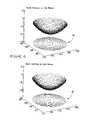
- FIG. 6shows a measured wavefront 56 and a modeled wavefront 58 for the calibration lens. Comparisons can be made between the measured and the modeled wavefronts, providing a means for part verification, for example.
- a calibration partis used.
- a plano-convex glass lensis used as a calibration part. Parameters such as index, center thickness, and radius of curvature are measured independently, providing a complete prescription for the lens.
- the prescription of the interferometerenables the generation of a modeled wavefront at the same location as the measured wavefront. With two wavefronts at the same location, and therefore at the same size, a difference wavefront can be computed by simply subtracting the modeled wavefront from the measured.
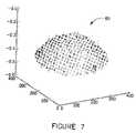
- FIG. 7depicts a difference wavefront 60 of the difference between the measured wavefront 56 and the modeled wavefront 58 .
- This differenceis computed at 99% of the diameter of the two wavefronts to avoid edge effects.
- the noise in the difference wavefront 60due to a combination of factors, obscures the general shape of the difference wavefront 60 .
- the noise in the difference wavefront 60can be alleviated in any appropriate manner.
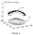
- a Zernike polynomialcan be applied to the difference wavefront 60 to remove the noise.
- Zernike polynomialsare known in the art.
- Application of Zernike polynomialsis known to cancel distortion.
- a Zernike fittingis used to remove high spatial frequency noise, and the Zernike coefficients are used to compute aberration information about the wavefront.
- FIG. 8show a Zernike surface 62 and image 64 thereof, after application of 36-term Zernike polynomials fit to the difference wavefront 60 .
- the Zernike surface 62illustrates that defocus is the dominant error in the comparison between measured and modeled wavefronts.
- a difference in power like thisis most likely due to a discrepancy in index of refraction for the test lens and the surrounding saline solution in the interferometer versus the values used in the model.
- the poweris measured at ⁇ 0.019 diopters. In air, this difference becomes ⁇ 0.054 diopters.
- this difference in powercan be converted to an uncertainty in index.
- interferogram of FIG. 9shows a localized defect 84 of a lens under test.
- transmitted wavefront determination utilizing the interferometer 12provides ability to detect defects in optical performance that cause deviations in the light path on the order of a fraction of the wavelength of light used.
- transmitted wavefront determination utilizing the interferometer 12can produce the spherical power of any spherical contact lens.
- cylindrical power and axiscan also be obtained.
- regions that deviate from other parts of a lensare detectable, as shown in FIG. 10 .
- FIG. 10shows a region 86 in which the fringes are slightly flattened.
- the region 68may not be characterized as a defect (e.g., defect 84 of FIG. 9 ), but will produce a different optical effect such as power change, spherical aberration, or the like.
- Transmitted wavefront determination utilizing the interferometer 12also can detect information on possible stress or other alterations in the periphery of the lens, as shown in regions 88 of FIG. 11 .
- the swirl or misalignment in the fringes 88 near the two fiducial marks 90indicates an area of possible stress and/or misalignment.
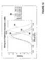
- FIG. 12shows plots 90 , 92 , 94 , and 96 of spherical aberration (SPHA) in diopters per square millimeter (D/mm 2 ) versus frequency for four different lenses. Each lens tested had a power of ⁇ 1.00 diopters (D). Further, statistical analysis of information obtained via wavefront analysis can be conducted as illustrated by statistic block 82 , wherein the mean and standard deviation of the spherical aberration for each lens 90 , 92 , 94 , and 96 are depicted.
- SPHAspherical aberration
- the thickness of toric lensescan be determined as illustrated in FIG. 13 .
- Toric contact lensesare spherocylinder lenses designed to correct astigmatism in the eye.
- FIG. 13the thicknesses of three lenses 100 , 102 , and 104 is depicted. The darker areas indicate increased thickness compared to lighter areas for each lens, having a range from 0.0 mm to 0.500 mm.
- FIG. 14is a cross-sectional view of the cuvette 28 shown in the interferometer 12 depicted in FIG. 1 .
- Materials used in manufacturing contact lensesinclude hydrogels, which are hygroscopic.
- the lensesare placed in the cuvette 28 , or water cell, to keeps them hydrated and stable in terms of refractive index.
- the cuvette 28comprises a compartment having two windows that are antireflection (AR) coated.
- ARantireflection
- the entire cuvetteinterfaces with a test configuration, such as the interferometer 12 for example, via a kinematic mount and by means of an automatic connection system that includes the mechanical linkage to the interferometer drive system and the electrical control and instrumentation circuits.
- An outer enclosurehouses all the constituents of the cuvette. The enclosure is configured to evenly circulate the test solution, to prevent the test solution from leaking, and to monitor the temperature of the test solution.
- a lens holdercontains one, or multiple, testing cells, configured to hold a lens submerged in a solution, and which can be moved within the cuvette's outer enclosure while maintaining the placement and orientation of the test lenses.
- a first windowis configured to allow the interferometer test arm beam to enter a cell with no change in collimation or in coherence length.
- a second windowis configured to allow the test arm beam to exit the cuvette after passing through the lens with no additional change to the exiting test arm beam.
- the centers of the two optical windowsare aligned with each other, with the movable lens holder mounted between. The holder is moved so as to position each cell, one at a time, between the first window and the second window.
- the cuvette kinematic mountis achieved by use of a dovetail slide, which provides the primary alignment of the cuvette to the mechanical and electrical connectors and sensors and provides vertical height registration use of locator pins and a resilient (e.g., spring-loaded) arm, which provides a radial force against the locator pins, to accurately and consistently locate the cuvette in a plane parallel to the dovetail slide.
- the mechanical linkageis designed to provide repeatable, positive engagement and vibration isolation between the cuvette and the interferometer without any preconditioning to the cuvette's linkage.
- Each cell in the lens holderhas a window that does not change the collimation or coherence length of an incident collimated beam, and which is transparent to the wavelength or wavelengths of the interferometer's coherent light source. This window forms the surface on which the test lens is mounted.
- the window in each cell in the lens holderis coplanar with all other cell windows in the lens holder.
- Each cell in the lens holderhas a tapered wall designed to allow for accurate and distortion-free mounting of the test lens in the cell.
- Each cellis designed so that the interferometer's imaging camera can image the entire lens.
- Each cell in the lens holderhas at least one channel to allow solution to flow. Both optical windows in the cuvette are transparent to the wavelength or wavelengths of the interferometer's coherent light source.
- test solution circulating through the cuvetteis optically transparent to the wavelength or wavelengths of the interferometer's coherent light source.
- Example test solutionsinclude saline solutions, buffered saline solution, de-ionized water, solutions with active pharmaceuticals, or a combination thereof.
- the outer enclosure of the cuvetteincludes inlet and outlet connections for a source of temperature controlled test solution.
- the outer enclosureis configured to monitor the temperature of the test solution using a temperature probe.
- the temperature probecomprises a resistance temperature detector (RTD) that provides information to an external temperature controller to help stabilize the temperature of the solution in the cuvette.
- RTDresistance temperature detector
- the outer enclosure of the cuvetteis constructed from an opaque polycarbonate material that is mechanically stable in the presence of the test solutions.
- the cuvetteis configured to handle a variety of types of lenses, such as hard contact lenses, hard refractive contact lenses, hard diffractive contact lenses, hard hybrid refractive/diffractive contact lenses, soft contact lenses, soft refractive contact lenses, soft diffractive contact lenses, soft hybrid refractive/diffractive contact lenses, hard contact lenses comprising an active pharmaceutical, soft contact lenses comprising an active pharmaceutical, single vision lenses, toric lenses, bifocal contact lenses, multifocal lenses, cosmetically tinted lenses, freeform lenses, an intraocular lenses, an intraocular refractive lenses, an intraocular diffractive lenses, intraocular hybrid refractive/diffractive lenses, accommodating lenses, spectacle lenses, refractive spectacle lenses, diffractive spectacle lenses, and hybrid refractive/diffractive spectacle lenses, for example.
- lensessuch as hard contact lenses, hard refractive contact lenses, hard diffractive contact lenses, hard hybrid refractive/diffractive contact lenses, soft contact lenses, soft refractive contact lenses, soft diffractive contact
- the cuvette 28is a vessel for holding contact lenses immersed in solution in such a way that the lenses can be tested using the interferometer 12 .
- the cuvette 28is designed to accommodate multiple lenses.
- the cuvette 28can hold 30 lenses.
- Each lenshas its own location (cell) in the cuvette 28 , and the cells are mobile within the cuvette 28 .
- Lensescan be positioned for testing within the cuvette 28 , and preferably are not deformed by the cuvette or any internal mounting within it. It is also preferably that the entire lens under test be visible. All windows of the cuvette preferably are of equal optical quality in terms of flatness to prevent adding additional power to the transmitted wavefront.
- the location and presentation of the lenspreferably is repeatable lens-to-lens and trial-to-trial. Insertion and removal of lenses into and from the cuvette 28 typically is simple and straightforward. Lenses preferably are not free to move outside their cells, and bubbles formed in the solution should not interfere with measurements. That is, the bubbles should not be visible in a cell.
- the cuvette 28comprises outer walls 106 and 108 .
- the portion 110or carousel, in the middle of the cuvette 28 , comprises multiple lens cells 112 .
- the carousel 110comprises 30 lens cells 112 .
- Each cell 112comprises of a tapered walls 114 (which can conform to a lens), channels 116 for fluid flow, and a window 118 at the bottom of the cell on which the lens rests.
- the outer walls 106 and 108can comprise any appropriate material.
- the outer walls 106 and 108comprise polycarbonate. Polycarbonate provides the following characteristics to the cuvette 28 : lightweight, opaque, chemically inert, and low water absorption, which keeps the cuvette 28 dimensionally stable.
- FIG. 15is an illustration of an expanded cross-sectional view of a portion of the cuvette 28 .
- Light from the interferometer 12enters the cuvette 28 through the top window 120 in the direction of arrow 122 , and travels down through the lens which is resting in its lens cell 112 , and then exits the cuvette through the bottom window 122 .
- This small gap 124is maintained throughout the cuvette 28 , and is designed to keep the lenses in their respective cells 112 during rotation.
- the outer windows 120 and 122are stepped to provide a channel 126 for an O-ring or gasket to sit and provide a seal around each window 120 , 122 .
- This configurationalso allows the windows to be tipped and/or tilted into alignment, rather than relying on a fixed mounting scheme.
- the middle glass window 128is also stepped, see area 130 , to provide consistent registration amongst all cells 112 .
- the middle window 128protrudes from the bottom of the carousel 110 to keep bubbles in the solution away from the central portion of the window 128 .
- the tapered sides 114 of each cell 112ease centering of the lens, and do not deform the lens in any way.
- the wall sides 114aid in unloading lenses, as lenses can be slid up the side of the cells 112 and then removed from the cuvette 28 once outside the cell 112 .
- Loading and unloading of lensescan be accomplished through a door 151 , or the like, of the cuvette 28 .
- the dooris attached to an interlock (see interlock 188 in FIG. 19 ) that prevents automatic carousel rotation when the door is open. No special tool is required to work with the lenses, for example a swab can be used to work with the lenses.
- the interferometer 12controls the cuvette 28 via automatic indexing.
- Automatic indexingcan be accomplished via any appropriate means.
- the cuvette 28can have its own motor and processor, and simply receive signals from the interferometer 12 .
- more controlis contained in the interferometer 12 , and less control contained in the cuvette 28 .
- the interferometer 12provides a means for rotation that mates with the cuvette 28 . This can be accomplished, for example, by use of a gear, belt, chain, rack and pinion or the like, or a combination thereof.
- FIG. 16depicts an exemplary coupling mechanism that comprises a single motor 132 , a gear box 134 , pulleys 136 , 138 , 140 , and a grooved belt 142 .
- the carousel 110 up through the cuvette pulley 138are contained within the cuvette 28 .
- the motor 132 , gear box 134 , drive pulley 140 , and tensioner pulleys 136are fixed components within the interferometer 12 .
- Couplingoccurs between the cuvette pulley 138 and geared belt 142 when the cuvette 28 is pushed into the interferometer 12 . This type of coupling provides significant engagement around the pulley, reducing the possibility of slippage. The large amount of engagement eases starting and stopping cuvette rotation.
- FIG. 17is a top view of an illustration of a cuvette positioning mechanism.
- the location of a cell 112is determined by two locator pins which are part of XY locator 146 and radial location 148 , respectively. Combined with a loose-fitting dovetail 144 , the two locator pins provide repeatable, kinematical positioning of the cuvette.
- the designed couplingallows for manual rotation.
- the sprocket 150(see FIG. 14 ) provides manual rotation and is clutched for safety purposes; a pinch point is avoided between the sprocket and interferometer when the cuvette is loaded into the system.
- the actuator arm 184 and crowder arm 186work as pair to provide a spring loaded force which keeps the cuvette 28 pressed against the XY locator 146 and the radial locator 148 via a radial force.
- the two arms 184 and 186enable kinematic loading of the cuvette 28 to the interferometer.
- Automatic indexingis provided by the wheel with flags 152 (see FIG. 14 ) located just below the sprocket 150 .
- the flags 152interface with positional sensors 154 attached to the interferometer 12 , as shown in FIG. 18 .
- the flags 152trigger the positional sensors 154 , which then send commands to slow and then stop the cuvette 28 .
- Only three cell position sensors 152are labeled in FIG. 18 for the sake of simplicity.
- the cuvette 28is slowed to minimize disturbing the loaded lenses. Lens positioning is independent of the mechanism used to rotate the cuvette 28 .
- the motorssimply start and stop based off signals from the positional sensors 154 . No counts or other motor settings are used to determine cell positions.
- Home position flag 156is used to initialize alignment of the cuvette 28 with the interferometer 12 .
- FIG. 19is a diagram of an enclosed cuvette 28 .
- the enclosed cuvette 28provides temperature stability by circulating solution between the cuvette 28 and an external chiller (external chiller not shown in FIG. 19 ).
- the design of the cuvette's interiorallows fluid to flow through and between cells 112 .
- the cuvettecomprises three elements for fluid control: a temperature probe 158 , an intake valve 160 , and a drain 162 .
- an overflow coupling 164is also provided.
- the temperature probe 158provides an electronic reading of the temperature of the fluid inside the cuvette 28 near the measurement windows.
- the intake valve 160 and drain 162provide ports for solution to circulate through the cuvette 28 .
- the intake portionallows solution to enter the cuvette 28 and the drain portion allows solution to exit the cuvette 28 .
- the intake valve 160 and drain 162interface with the external chiller and pump through tubes equipped with the appropriate fittings.
- An interferometer 12 with cuvette 28provides a viable method and system for utilizing wavefront analysis to test contact lenses. Testing against a planar reference wavefront enables the determination of the absolute lens power.
- the increase in dynamic range due to the immersion of the lenses in saline solutionallows for a wide range of prescriptions to be tested without the use of null optics or other means of removing the bulk power of the lens.
- This method and systemis applicable to a wide variety of lenses, including spherical lenses. No assumption is necessary regarding the type of part being tested. All that is needed is the prescription of the test lens.
- FIG. 20is a flow diagram of an example process for aligning detectors of an interferometer configuration for obtaining a wavefront of a lens.
- the camerase.g., the imaging camera 38 and the science camera 34
- Alignmentcomprises converting the imaging camera's 38 coordinate system to the science camera's 34 coordinate system.
- an image point in the imaging camera's 38is selected and a corresponding image point is determined in the science camera 34 .
- the image camera 38 and the science camera 34differ, at least, in magnification capability.
- the camerascan differ in respective shift in x-axis, y-axis, and/or rotation of corresponding image points.
- a test targete.g., a target lens having known reference points
- FIG. 21shows an example target lens 178 .
- the target lens 178comprises ten concentric circles.
- Example image point 180has a location of 0 on the x-axis and 1 on the y-axis. This is denoted as (0,1) in FIG. 21 .
- Example image point 182has a location of ⁇ 2 on the x-axis and 0 on the y-axis. This is denoted as ( ⁇ 2,0) in FIG. 21 .
- points of intersections with the x and y axes and the circlesare utilized.
- the magnification of the first detectore.g., the science camera 34
- the magnification of the science camerais referred to herein as ms.
- the magnification of the second detectore.g., the imaging camera 38
- the magnification of the imaging camerais referred to herein as m I .
- the location on the x-axis of the science camera 34 corresponding to the location of the x-axis location zero on the imaging camera 38is determined. This location on the x-axis of the science camera 34 is referred to herein as x 0 .
- the location on the y-axis of the science camera 34 corresponding to the location of the y-axis location zero on the imaging camera 38is determined.
- This location on the y-axis of the science camera 34is referred to herein as y 0 .
- the angle of rotational difference between the science camera 34 and the imaging camera 38is determined at step 174 .
- This angle of rotational differenceis referred to herein as ⁇ S .
- using the determined values of m I , m S , x 0 , y 0 , and ⁇ Sthe location of the center of the target lens measured in the imaging camera 38 is converted to the corresponding location in the science camera 34 . More generally, the values of m I , m S , x 0 , y 0 , and ⁇ S are utilized to convert the imaging camera's 38 coordinate system to the science camera's 34 coordinate system.
- the coordinates in the coordinate system of the science camera 34are converted from the coordinates in the coordinate system of the science camera for a corresponding point in accordance with the following formulas.
- x S( x I *cos ⁇ S +y I *sin ⁇ S ) m I /m S +x 0 (4)
- y S( ⁇ x I *sin ⁇ S +y I *cos ⁇ S ) m I /m S +y 0 , (5)
- x srepresents an x-axis location in the science camera corresponding to the x-axis location of the corresponding point in the imaging camera
- y Srepresents the y-axis location in the science camera corresponding to the y-axis location of the corresponding point in the imaging camera
- m Srepresents the magnification of the science camera 34
- m Irepresents the magnification of the imaging camera 38
- x 0represents the location on the x-axis of the science camera 34 of the x-axis location
- the interferograms obtained from the science camera and the imaging cameraare combined into a single wavefront for a portion of the lens under test.
- the interference patterns at both the science camera and the imaging cameraare captured.
- the modulationis computed for the imaging camera. Computing the modulation results in a value for each pixel of the interference pattern captured by the imaging camera.
- the modulationis used to identify pixels associated with the edge of the lens.
- An ellipseis fit to the identified pixels and the center of the ellipse is determined.
- the determined centerwhich represents the center of the lens as captured by the imaging camera, is mapped to the center of the science camera.
- the appropriate region of the interference pattern captured by the science camerais masked to leave the region of interest of the lens.
- the transmitted wavefront of this region of interestis computed for further analysis.
- the various techniques described hereincan be implemented in connection with hardware or software or, where appropriate, with a combination of both.
- the methods for the use of interferometry for transmitted wavefront testing of lensescan take the form of program code (i.e., instructions) embodied in tangible media, such as floppy diskettes, CD-ROMs, hard drives, or any other machine-readable storage medium, wherein, when the program code is loaded into and executed by a machine, such as a computer, the machine becomes an apparatus for the use of interferometry for transmitted wavefront testing of lenses.
- the program(s)can be implemented in assembly or machine language, if desired.
- the languagecan be a compiled or interpreted language, and combined with hardware implementations.
- the methods for the use of interferometry for transmitted wavefront testing of lensesalso can be practiced via communications embodied in the form of program code that is transmitted over some transmission medium, such as over electrical wiring or cabling, through fiber optics, or via any other form of transmission, wherein, when the program code is received and loaded into and executed by a machine, such as an EPROM, a gate array, a programmable logic device (PLD), a client computer, or the like, the machine becomes an apparatus for the use of interferometry for transmitted wavefront testing of lenses.
- a machinesuch as an EPROM, a gate array, a programmable logic device (PLD), a client computer, or the like, the machine becomes an apparatus for the use of interferometry for transmitted wavefront testing of lenses.
- PLDprogrammable logic device
- the program codeWhen implemented on a general-purpose processor, the program code combines with the processor to provide a unique apparatus that operates to invoke the functionality the use of interferometry for transmitted wavefront testing of lenses. Additionally, any storage techniques used in connection with the use of interferometry for transmitted wavefront testing of lenses can invariably be a combination of hardware and software.
- interferometry for transmitted wavefront testing of lenseshas been described in connection with the example embodiments of the various figures, it is to be understood that other similar embodiments can be used or modifications and additions can be made to the described embodiments for performing the same functions for the use of interferometry for transmitted wavefront testing of lenses without deviating therefrom. Therefore, the use of interferometry for transmitted wavefront testing of lenses as described herein should not be limited to any single embodiment, but rather should be construed in breadth and scope in accordance with the appended claims.
Landscapes
- General Physics & Mathematics (AREA)
- Physics & Mathematics (AREA)
- Chemical & Material Sciences (AREA)
- Analytical Chemistry (AREA)
- Pathology (AREA)
- Health & Medical Sciences (AREA)
- Life Sciences & Earth Sciences (AREA)
- Biochemistry (AREA)
- General Health & Medical Sciences (AREA)
- Immunology (AREA)
- Chemical Kinetics & Catalysis (AREA)
- Testing Of Optical Devices Or Fibers (AREA)
- Investigating Or Analysing Materials By Optical Means (AREA)
- Instruments For Measurement Of Length By Optical Means (AREA)
- Length Measuring Devices By Optical Means (AREA)
- Eyeglasses (AREA)
- Optical Measuring Cells (AREA)
- Mounting And Adjusting Of Optical Elements (AREA)
Abstract
Description
Img{W}=W+A{W} (1)
where W represents the original wavefront, and A{W} represents the induced aberrations. The notation A{W} is used to indicate that the induced aberrations are wavefront dependent. The
OPDT=Img{WT}−Img{WR}=(WT+A{WT})−(WR+A{WR}) (2)
{tilde over (W)}T=Img−1{WT+A{WT})=Img−1{OPDT+Img{WR}). (3)
xS=(xI*cos θS+yI*sin θS)mI/mS+x0 (4)
yS=(−xI*sin θS+yI*cos θS)mI/mS+y0, (5)
where: xsrepresents an x-axis location in the science camera corresponding to the x-axis location of the corresponding point in the imaging camera, ySrepresents the y-axis location in the science camera corresponding to the y-axis location of the corresponding point in the imaging camera, mSrepresents the magnification of the science camera34, mIrepresents the magnification of the
Claims (60)
xS=(x1*cosθS+y1*sinθS)m1/mS+x0;
yS=(−x1*sinθS+y1*cosθS)m1/mS+y0,
Priority Applications (1)
| Application Number | Priority Date | Filing Date | Title |
|---|---|---|---|
| US11/962,555US7688453B2 (en) | 2006-12-21 | 2007-12-21 | Interferometry testing of lenses, and systems and devices for same |
Applications Claiming Priority (2)
| Application Number | Priority Date | Filing Date | Title |
|---|---|---|---|
| US87131906P | 2006-12-21 | 2006-12-21 | |
| US11/962,555US7688453B2 (en) | 2006-12-21 | 2007-12-21 | Interferometry testing of lenses, and systems and devices for same |
Publications (2)
| Publication Number | Publication Date |
|---|---|
| US20080285019A1 US20080285019A1 (en) | 2008-11-20 |
| US7688453B2true US7688453B2 (en) | 2010-03-30 |
Family
ID=39327060
Family Applications (2)
| Application Number | Title | Priority Date | Filing Date |
|---|---|---|---|
| US11/962,662Active2029-05-08US8427636B2 (en) | 2006-12-21 | 2007-12-21 | Cuvette for ophthalmic lens |
| US11/962,555Active2028-06-06US7688453B2 (en) | 2006-12-21 | 2007-12-21 | Interferometry testing of lenses, and systems and devices for same |
Family Applications Before (1)
| Application Number | Title | Priority Date | Filing Date |
|---|---|---|---|
| US11/962,662Active2029-05-08US8427636B2 (en) | 2006-12-21 | 2007-12-21 | Cuvette for ophthalmic lens |
Country Status (12)
| Country | Link |
|---|---|
| US (2) | US8427636B2 (en) |
| EP (2) | EP2095063B1 (en) |
| JP (3) | JP5122581B2 (en) |
| KR (2) | KR101387994B1 (en) |
| CN (2) | CN101680742B (en) |
| AR (4) | AR064644A1 (en) |
| AU (2) | AU2007336799B2 (en) |
| BR (2) | BRPI0720851B1 (en) |
| CA (2) | CA2672900C (en) |
| SG (1) | SG177910A1 (en) |
| TW (2) | TWI434023B (en) |
| WO (2) | WO2008080074A2 (en) |
Cited By (18)
| Publication number | Priority date | Publication date | Assignee | Title |
|---|---|---|---|---|
| US20080316499A1 (en)* | 2007-06-20 | 2008-12-25 | Korb Donald R | Tear film measurement |
| US20080319323A1 (en)* | 2007-06-20 | 2008-12-25 | Gravely Benjamin T | Tear film measurement |
| US20100253907A1 (en)* | 2009-04-01 | 2010-10-07 | Tearscience, Inc. | Ocular surface interferometery (OSI) devices and systems for imaging, processing, and/or displaying an ocular tear film |
| WO2012037694A3 (en)* | 2010-09-25 | 2012-06-21 | Queen's University At Kingston | Methods and systems for coherent imaging and feedback control for modification of materials |
| US8888286B2 (en) | 2009-04-01 | 2014-11-18 | Tearscience, Inc. | Full-eye illumination ocular surface imaging of an ocular tear film for determining tear film thickness and/or providing ocular topography |
| US8915592B2 (en) | 2009-04-01 | 2014-12-23 | Tearscience, Inc. | Apparatuses and methods of ocular surface interferometry (OSI) employing polarization and subtraction for imaging, processing, and/or displaying an ocular tear film |
| US9339177B2 (en) | 2012-12-21 | 2016-05-17 | Tearscience, Inc. | Full-eye illumination ocular surface imaging of an ocular tear film for determining tear film thickness and/or providing ocular topography |
| US9642520B2 (en) | 2009-04-01 | 2017-05-09 | Tearscience, Inc. | Background reduction apparatuses and methods of ocular surface interferometry (OSI) employing polarization for imaging, processing, and/or displaying an ocular tear film |
| US9757817B2 (en) | 2013-03-13 | 2017-09-12 | Queen's University At Kingston | Methods and systems for characterizing laser machining properties by measuring keyhole dynamics using interferometry |
| US9795290B2 (en) | 2013-11-15 | 2017-10-24 | Tearscience, Inc. | Ocular tear film peak detection and stabilization detection systems and methods for determining tear film layer characteristics |
| US9888839B2 (en) | 2009-04-01 | 2018-02-13 | Tearscience, Inc. | Methods and apparatuses for determining contact lens intolerance in contact lens wearer patients based on dry eye tear film characteristic analysis and dry eye symptoms |
| US10124410B2 (en) | 2010-09-25 | 2018-11-13 | Ipg Photonics Corporation | Methods and systems for coherent imaging and feedback control for modification of materials |
| US10278587B2 (en) | 2013-05-03 | 2019-05-07 | Tearscience, Inc. | Eyelid illumination systems and method for imaging meibomian glands for meibomian gland analysis |
| US11458566B2 (en) | 2018-12-19 | 2022-10-04 | Ipg Photonics Corporation | Monitoring material processing using imaging signal density determined from inline coherent imaging (ICI) |
| US11852794B2 (en) | 2018-11-01 | 2023-12-26 | Hust-Suzhou Institute For Brainsmatics | High-throughput optical sectioning imaging method and imaging system |
| US12097572B2 (en) | 2018-07-19 | 2024-09-24 | Ipg Photonics Corporation | Systems and methods for monitoring and/or controlling wobble-processing using inline coherent imaging (ICI) |
| US12397368B2 (en) | 2010-09-25 | 2025-08-26 | Ipg Photonics Corporation | Methods and systems for coherent imaging and feedback control for modification of materials using dynamic optical path switch in the reference arms |
| US12442717B2 (en) | 2023-02-03 | 2025-10-14 | Onto Innovation Inc. | Interferometer with auxiliary lens for measurement of a transparent test object |
Families Citing this family (37)
| Publication number | Priority date | Publication date | Assignee | Title |
|---|---|---|---|---|
| JP5325481B2 (en)* | 2008-07-02 | 2013-10-23 | オリンパス株式会社 | Measuring method of optical element and manufacturing method of optical element |
| US20100081772A1 (en)* | 2008-09-30 | 2010-04-01 | Diana Zanini | Process for forming silicone hydrogel articles having improved optical properties |
| US20130203812A1 (en) | 2008-09-30 | 2013-08-08 | Johnson & Johnson Vision Care, Inc. | Ionic silicone hydrogels comprising pharmaceutical and/or nutriceutical components and having improved hydrolytic stability |
| US8470906B2 (en) | 2008-09-30 | 2013-06-25 | Johnson & Johnson Vision Care, Inc. | Ionic silicone hydrogels having improved hydrolytic stability |
| CN101667136B (en)* | 2009-09-27 | 2012-09-05 | 北京航空航天大学 | Star map simulation method based on forward ray tracking technology |
| US9522980B2 (en) | 2010-05-06 | 2016-12-20 | Johnson & Johnson Vision Care, Inc. | Non-reactive, hydrophilic polymers having terminal siloxanes and methods for making and using the same |
| WO2012001929A1 (en)* | 2010-07-01 | 2012-01-05 | パナソニック株式会社 | Wavefront aberration measuring apparatus and wavefront aberration measuring method |
| US20130203813A1 (en) | 2011-05-04 | 2013-08-08 | Johnson & Johnson Vision Care, Inc. | Medical devices having homogeneous charge density and methods for making same |
| US9170349B2 (en) | 2011-05-04 | 2015-10-27 | Johnson & Johnson Vision Care, Inc. | Medical devices having homogeneous charge density and methods for making same |
| SG195400A1 (en)* | 2012-05-10 | 2013-12-30 | Menicon Singapore Pte Ltd | Systems and methods for the inspection of contact lenses |
| US9244196B2 (en) | 2012-05-25 | 2016-01-26 | Johnson & Johnson Vision Care, Inc. | Polymers and nanogel materials and methods for making and using the same |
| US10073192B2 (en) | 2012-05-25 | 2018-09-11 | Johnson & Johnson Vision Care, Inc. | Polymers and nanogel materials and methods for making and using the same |
| US9297929B2 (en) | 2012-05-25 | 2016-03-29 | Johnson & Johnson Vision Care, Inc. | Contact lenses comprising water soluble N-(2 hydroxyalkyl) (meth)acrylamide polymers or copolymers |
| CN104704339A (en)* | 2012-09-28 | 2015-06-10 | 诺华股份有限公司 | Method for automated in-line determination of center thickness of an ophthalmic lens |
| JP6029429B2 (en)* | 2012-11-19 | 2016-11-24 | キヤノン株式会社 | Wavefront aberration measuring method, wavefront aberration measuring apparatus, and optical system manufacturing method |
| GB201302095D0 (en)* | 2013-02-06 | 2013-03-20 | Optimec Ltd | Lens Measurement |
| US20160223429A1 (en)* | 2013-09-11 | 2016-08-04 | Novartis Ag | Contact lens inspection system and method |
| CA2941655C (en)* | 2014-03-05 | 2021-03-09 | Arizona Board Of Regents On Behalf Of The University Of Arizona | Wearable 3d augmented reality display with variable focus and/or object recognition |
| EP3186588B1 (en)* | 2014-08-28 | 2018-10-24 | Johnson & Johnson Vision Care Inc. | In-line inspection of ophthalmic device with auto-alignment system and interferometer |
| EP3218685B1 (en)* | 2014-11-11 | 2021-06-16 | Brien Holden Vision Institute | Systems and methods for determining the quality of a reproduced (manufactured) optic device |
| HUE049738T2 (en)* | 2014-11-25 | 2020-10-28 | Alcon Inc | Cuvette system and methods for the inspection of ophthalmic lenses |
| WO2016123167A1 (en)* | 2015-01-28 | 2016-08-04 | The United States Of America, As Represented By The Secretary, Department Of Health & Human Services | Confocal laser method and device for measurement of optical properties of toric intraocular lenses |
| US10136120B2 (en) | 2016-04-15 | 2018-11-20 | Microsoft Technology Licensing, Llc | Depth sensing using structured illumination |
| CN106018432A (en)* | 2016-05-10 | 2016-10-12 | 长春博信光电子有限公司 | Large-size optical lens surface quality detection method and system |
| CN109791198B (en)* | 2016-08-15 | 2023-08-15 | 代表亚利桑那大学的亚利桑那校董会 | Novel automotive radar using 3D printed luneberg lenses |
| US20190281936A1 (en)* | 2018-03-14 | 2019-09-19 | Menicon Co. Ltd. | Contact lens container with biomarker detection |
| SG10201803290VA (en)* | 2018-04-19 | 2019-11-28 | Emage Vision Pte Ltd | System and method for inspecting optical power and thickness of ophthalmic lenses immersed in a solution |
| ES2736038B2 (en)* | 2018-06-22 | 2021-04-06 | Univ Burgos | DEVICE FOR THE DETECTION AND MEASUREMENT OF AT LEAST ONE ANALYTE IN AQUEOUS MEDIUM AND PROCEDURE FOR THE USE OF THE SAME |
| US11143503B2 (en)* | 2018-08-07 | 2021-10-12 | Kimball Electronics Indiana, Inc. | Interferometric waviness detection systems |
| IL318088A (en)* | 2019-01-10 | 2025-02-01 | 6 OVER 6 VISION Ltd | Apparatus, system, and method of determining one or more parameters of a lens |
| US10848744B2 (en) | 2019-02-27 | 2020-11-24 | Ford Global Technologies, Llc | Vehicle camera alignment |
| CN110118646B (en)* | 2019-06-04 | 2021-02-26 | 大连鉴影光学科技有限公司 | Glasses parameter detection device and method based on synthetic moire fringe technology |
| CN112556990B (en)* | 2019-09-10 | 2025-02-14 | 宁波法里奥光学科技发展有限公司 | Lens refractive index measuring device and measuring method thereof |
| WO2021124101A1 (en)* | 2019-12-18 | 2021-06-24 | Alcon Inc. | Cuvette for optical analyses |
| US12196944B2 (en) | 2020-01-09 | 2025-01-14 | Kimball Electronics Indiana, Inc. | Imaging system for leak detection |
| US11861823B2 (en)* | 2021-04-27 | 2024-01-02 | Johnson & Johnson Vision Care, Inc. | Microfluidic device and method for quantifying contact lens deposition |
| CN114199522A (en)* | 2021-11-30 | 2022-03-18 | 宁波法里奥光学科技发展有限公司 | Optical lens parameter measuring device and method |
Citations (14)
| Publication number | Priority date | Publication date | Assignee | Title |
|---|---|---|---|---|
| US3942952A (en) | 1974-08-22 | 1976-03-09 | The Perkin-Elmer Corporation | Sample platter moisturizing system |
| US4313735A (en) | 1979-08-22 | 1982-02-02 | Hitachi, Ltd. | Automatic chemical analyzing method and apparatus |
| CA1233976A (en) | 1985-04-17 | 1988-03-15 | Jacob G. Sivak | Method and apparatus for in vitro evaluation of focal length and focal length changes in lenses from human and animals eyes |
| US5151752A (en)* | 1988-06-16 | 1992-09-29 | Asahi Kogaku Kogyo K.K. | Method of measuring refractive indices of lens and sample liquid |
| EP0604173A2 (en) | 1992-12-21 | 1994-06-29 | JOHNSON & JOHNSON VISION PRODUCTS, INC. | Apparatus for carrying ophthalmic lenses |
| US5818573A (en) | 1997-02-06 | 1998-10-06 | Pbh, Inc. | Opthalmic lens inspection system |
| WO1999026052A2 (en) | 1997-11-14 | 1999-05-27 | Wesley-Jessen Corporation | Automatic lens inspection system |
| US5963318A (en)* | 1998-08-07 | 1999-10-05 | Bio-Tek Holdings, Inc. | Method of and apparatus for performing fixed pathlength vertical photometry |
| US6597442B2 (en)* | 2000-03-31 | 2003-07-22 | Pioneer Corporation | Apparatus for measuring aberration of a lens and an apparatus for adjusting a position of the lens |
| US20040008877A1 (en) | 2002-02-15 | 2004-01-15 | Ocular Sciences, Inc. | Systems and methods for inspection of ophthalmic lenses |
| US6765661B2 (en)* | 2001-03-09 | 2004-07-20 | Novartis Ag | Lens inspection |
| US6909503B2 (en)* | 2001-08-17 | 2005-06-21 | Novartis Ag | Cuvette for lens inspection |
| EP1544601A2 (en) | 2003-12-19 | 2005-06-22 | Hitachi High-Technologies Corporation | Air bubbles removing system in an automatic analyzer |
| WO2006091415A2 (en) | 2005-02-24 | 2006-08-31 | Zygo Corporation | Scanning interferometer for aspheric surfaces and wavefronts |
Family Cites Families (27)
| Publication number | Priority date | Publication date | Assignee | Title |
|---|---|---|---|---|
| US3606997A (en)* | 1968-07-01 | 1971-09-21 | Dole Eng Co James | Preserving products in sealed containers |
| US3555284A (en)* | 1968-12-18 | 1971-01-12 | Norman G Anderson | Multistation, single channel analytical photometer and method of use |
| US4347000A (en)* | 1979-12-26 | 1982-08-31 | The Perkin-Elmer Corporation | Interferometric system |
| JP2678463B2 (en)* | 1988-06-16 | 1997-11-17 | 旭光学工業株式会社 | Refractive index measurement method |
| ES2085854T3 (en)* | 1988-08-02 | 1996-06-16 | Abbott Lab | METHOD AND DEVICE FOR THE PRODUCTION OF CALIBRATION DATA FOR ANALYSIS. |
| CH676656A5 (en)* | 1988-09-07 | 1991-02-28 | Fritz Dr Med Bieri | |
| AU642768B2 (en)* | 1990-10-02 | 1993-10-28 | Ciba-Geigy Ag | A method of surface-cleaning and/or sterilising optical components, especially contact lenses |
| AU656826B2 (en)* | 1991-10-31 | 1995-02-16 | Microscan, Inc. | Specimen processing and analyzing systems with associated fluid dispensing apparatus |
| JP2890082B2 (en) | 1991-12-27 | 1999-05-10 | 信越半導体株式会社 | Wafer inspection method and apparatus |
| NZ250042A (en)* | 1992-12-21 | 1997-01-29 | Johnson & Johnson Vision Prod | Robotic inspection of ophthalmic lenses |
| CA2169141A1 (en)* | 1995-04-07 | 1996-10-08 | Ivan Prikryl | Interferometer having a micromirror |
| JPH09288040A (en)* | 1996-04-19 | 1997-11-04 | Topcon Corp | Lens meter |
| JPH10268200A (en)* | 1997-03-24 | 1998-10-09 | Olympus Optical Co Ltd | Interference microscope device |
| JPH1137937A (en) | 1997-07-17 | 1999-02-12 | Ricoh Co Ltd | Apparatus for measuring refractive index distribution and method for measuring refractive index distribution using the apparatus |
| JP3913407B2 (en)* | 1999-07-09 | 2007-05-09 | 株式会社リコー | Refractive index distribution measuring apparatus and method |
| KR20020006029A (en)* | 2000-01-14 | 2002-01-18 | 추후제출 | Measurement of back radius of curvature and center material thickness of a contact lens in solution |
| JP2001304826A (en)* | 2000-04-24 | 2001-10-31 | Ricoh Co Ltd | 3D shape measuring device |
| JP2002005619A (en)* | 2000-06-21 | 2002-01-09 | Olympus Optical Co Ltd | Interference measurement method and device and object measured by the method or device |
| US6924898B2 (en)* | 2000-08-08 | 2005-08-02 | Zygo Corporation | Phase-shifting interferometry method and system |
| JP2002206915A (en)* | 2001-01-09 | 2002-07-26 | Nikon Corp | Calibration method of abscissa of surface shape measuring device and surface shape measuring device |
| US6626535B2 (en)* | 2000-12-29 | 2003-09-30 | Bausch & Lomb Incorporated | Lens-eye model and method for predicting in-vivo lens performance |
| ATE297546T1 (en)* | 2001-02-09 | 2005-06-15 | Hoya Corp | LENS METER FOR MEASURING THE PROPERTIES OF A GLASS OR CONTACT LENS |
| JP2003098040A (en)* | 2001-09-25 | 2003-04-03 | Ricoh Co Ltd | Optical system evaluation apparatus and method |
| JP3827619B2 (en)* | 2002-07-11 | 2006-09-27 | 株式会社トプコン | Optical characteristic measuring method for lens and lens meter |
| JP2004045288A (en)* | 2002-07-12 | 2004-02-12 | Nippon Sheet Glass Co Ltd | Measuring instrument for lens |
| US7142311B2 (en)* | 2004-05-18 | 2006-11-28 | Zygo Corporation | Methods and systems for determining optical properties using low-coherence interference signals |
| JP2005345288A (en)* | 2004-06-03 | 2005-12-15 | Olympus Corp | Mach-zehnder interferometer and inspection method of optical element by mach-zehnder interferometer |
- 2007
- 2007-12-21ARARP070105812Apatent/AR064644A1/ennot_activeApplication Discontinuation
- 2007-12-21CACA2672900Apatent/CA2672900C/ennot_activeExpired - Fee Related
- 2007-12-21CACA2673200Apatent/CA2673200C/ennot_activeExpired - Fee Related
- 2007-12-21CNCN200780047481XApatent/CN101680742B/enactiveActive
- 2007-12-21TWTW096149557Apatent/TWI434023B/enactive
- 2007-12-21BRBRPI0720851-0Apatent/BRPI0720851B1/ennot_activeIP Right Cessation
- 2007-12-21ARARP070105811Apatent/AR064643A1/ennot_activeApplication Discontinuation
- 2007-12-21JPJP2009543257Apatent/JP5122581B2/enactiveActive
- 2007-12-21CNCN2007800516047Apatent/CN101688767B/enactiveActive
- 2007-12-21SGSG2011094794Apatent/SG177910A1/enunknown
- 2007-12-21AUAU2007336799Apatent/AU2007336799B2/enactiveActive
- 2007-12-21BRBRPI0720499-0Apatent/BRPI0720499A2/ennot_activeIP Right Cessation
- 2007-12-21KRKR1020097012749Apatent/KR101387994B1/enactiveActive
- 2007-12-21AUAU2007336715Apatent/AU2007336715B2/enactiveActive
- 2007-12-21KRKR1020097012750Apatent/KR101404427B1/enactiveActive
- 2007-12-21JPJP2009543258Apatent/JP5813288B2/enactiveActive
- 2007-12-21TWTW096149561Apatent/TWI449893B/enactive
- 2007-12-21USUS11/962,662patent/US8427636B2/enactiveActive
- 2007-12-21WOPCT/US2007/088583patent/WO2008080074A2/enactiveApplication Filing
- 2007-12-21EPEP07869768.7Apatent/EP2095063B1/enactiveActive
- 2007-12-21EPEP07869763.8Apatent/EP2097712B1/enactiveActive
- 2007-12-21USUS11/962,555patent/US7688453B2/enactiveActive
- 2007-12-21WOPCT/US2007/088588patent/WO2008080076A2/enactiveApplication Filing
- 2012
- 2012-05-03ARARP120101560Apatent/AR086258A2/ennot_activeApplication Discontinuation
- 2013
- 2013-08-02JPJP2013161259Apatent/JP5833063B2/enactiveActive
- 2015
- 2015-04-20ARARP150101182Apatent/AR100140A2/enunknown
Patent Citations (14)
| Publication number | Priority date | Publication date | Assignee | Title |
|---|---|---|---|---|
| US3942952A (en) | 1974-08-22 | 1976-03-09 | The Perkin-Elmer Corporation | Sample platter moisturizing system |
| US4313735A (en) | 1979-08-22 | 1982-02-02 | Hitachi, Ltd. | Automatic chemical analyzing method and apparatus |
| CA1233976A (en) | 1985-04-17 | 1988-03-15 | Jacob G. Sivak | Method and apparatus for in vitro evaluation of focal length and focal length changes in lenses from human and animals eyes |
| US5151752A (en)* | 1988-06-16 | 1992-09-29 | Asahi Kogaku Kogyo K.K. | Method of measuring refractive indices of lens and sample liquid |
| EP0604173A2 (en) | 1992-12-21 | 1994-06-29 | JOHNSON & JOHNSON VISION PRODUCTS, INC. | Apparatus for carrying ophthalmic lenses |
| US5818573A (en) | 1997-02-06 | 1998-10-06 | Pbh, Inc. | Opthalmic lens inspection system |
| WO1999026052A2 (en) | 1997-11-14 | 1999-05-27 | Wesley-Jessen Corporation | Automatic lens inspection system |
| US5963318A (en)* | 1998-08-07 | 1999-10-05 | Bio-Tek Holdings, Inc. | Method of and apparatus for performing fixed pathlength vertical photometry |
| US6597442B2 (en)* | 2000-03-31 | 2003-07-22 | Pioneer Corporation | Apparatus for measuring aberration of a lens and an apparatus for adjusting a position of the lens |
| US6765661B2 (en)* | 2001-03-09 | 2004-07-20 | Novartis Ag | Lens inspection |
| US6909503B2 (en)* | 2001-08-17 | 2005-06-21 | Novartis Ag | Cuvette for lens inspection |
| US20040008877A1 (en) | 2002-02-15 | 2004-01-15 | Ocular Sciences, Inc. | Systems and methods for inspection of ophthalmic lenses |
| EP1544601A2 (en) | 2003-12-19 | 2005-06-22 | Hitachi High-Technologies Corporation | Air bubbles removing system in an automatic analyzer |
| WO2006091415A2 (en) | 2005-02-24 | 2006-08-31 | Zygo Corporation | Scanning interferometer for aspheric surfaces and wavefronts |
Non-Patent Citations (7)
| Title |
|---|
| Born,M. et al., Principles of Optics, Sixth (Corrected) Edition, Cambridge University Press, Cambridge, UK, 1980, pp. 312-316. |
| Gappinger, R.O. et al., "Iterative Reverse Optimization Procedure for Calibration of Aspheric Wave-Front Measurements on a Nonnull Interferometer", Applied Optics, Sep. 20, 2004, 43(27), 5152-5161, XP002479854. |
| Greivankamp, J.E. et al., "Design of a Nonnull Interferometer for Aspheric Wave Fronts", Applied Optics,Sep. 20, 2004, 43(27), 5143-5151. |
| Greivenkamp, J. E. et al., "Phase Shifting Interferometers", in Optical Shop Testing, Second Edition, D. Malacara, ed., Ch. 14, pp. 501-598, John Wiley & Sons, New York, 1992. |
| Hecht, E., Optics, Second Edition, Addison-Wesley, Reading, MA 1987, pp. 346-361. |
| Williby, G. et al., "Interferometric testing of Soft Contact Lenses", Proceedings of SPIE- The International Society for Optical Engineering, 2003, 5180, 329-339, XP 002479853. |
| Wyant, J.C. et al., "Basic Wavefront Aberration Theory for Optical Metrology," in Applied Optics and Optical Engineering, R.R. Shannon and J.C. Wyant, eds., vol. XI, Ch. 1, pp. 28-39, Academic Press, Boston, 1992. |
Cited By (57)
| Publication number | Priority date | Publication date | Assignee | Title |
|---|---|---|---|---|
| US7988294B2 (en) | 2007-06-20 | 2011-08-02 | Tearscience, Inc. | Tear film measurement |
| US20080319323A1 (en)* | 2007-06-20 | 2008-12-25 | Gravely Benjamin T | Tear film measurement |
| US20100085540A1 (en)* | 2007-06-20 | 2010-04-08 | Tearscience, Inc. | Tear film measurement |
| US7758190B2 (en) | 2007-06-20 | 2010-07-20 | Tearscience, Inc. | Tear film measurement |
| US20080316499A1 (en)* | 2007-06-20 | 2008-12-25 | Korb Donald R | Tear film measurement |
| US8591033B2 (en) | 2007-06-20 | 2013-11-26 | Tearscience, Inc. | Tear film measurement |
| US8585204B2 (en) | 2007-06-20 | 2013-11-19 | Tearscience, Inc. | Tear film measurement |
| US8192026B2 (en) | 2007-06-20 | 2012-06-05 | Tearscience, Inc. | Tear film measurement |
| US20100259722A1 (en)* | 2009-04-01 | 2010-10-14 | Tearscience, Inc. | Ocular surface interferometry (OSI) methods for imaging, processing, and/or displaying an ocular tear film |
| US11259700B2 (en) | 2009-04-01 | 2022-03-01 | Tearscience Inc | Ocular surface interferometry (OSI) for imaging, processing, and/or displaying an ocular tear film |
| US9888839B2 (en) | 2009-04-01 | 2018-02-13 | Tearscience, Inc. | Methods and apparatuses for determining contact lens intolerance in contact lens wearer patients based on dry eye tear film characteristic analysis and dry eye symptoms |
| US11771317B2 (en) | 2009-04-01 | 2023-10-03 | Tearscience, Inc. | Ocular surface interferometry (OSI) for imaging, processing, and/or displaying an ocular tear film |
| US8215774B2 (en) | 2009-04-01 | 2012-07-10 | Tearscience, Inc. | Ocular surface interferometry (OSI) devices and systems for imaging and measuring ocular tear film layer thickness(es) |
| US8545017B2 (en) | 2009-04-01 | 2013-10-01 | Tearscience, Inc. | Ocular surface interferometry (OSI) methods for imaging, processing, and/or displaying an ocular tear film |
| US20100259723A1 (en)* | 2009-04-01 | 2010-10-14 | Tearscience, Inc. | Ocular surface interferometry (OSI) methods for imaging and measuring ocular tear film layer thickness(es) |
| US20100259721A1 (en)* | 2009-04-01 | 2010-10-14 | Tearscience, Inc. | Ocular surface interferometry (OSI) devices and systems for imaging and measuring ocular tear film layer thickness (ES) |
| US8746883B2 (en) | 2009-04-01 | 2014-06-10 | Tearscience, Inc. | Ocular surface interferometery (OSI) devices and systems for imaging, processing, and/or displaying an ocular tear film |
| US8092023B2 (en) | 2009-04-01 | 2012-01-10 | Tearscience, Inc. | Ocular surface interferometry (OSI) methods for imaging and measuring ocular tear film layer thickness(es) |
| US8888286B2 (en) | 2009-04-01 | 2014-11-18 | Tearscience, Inc. | Full-eye illumination ocular surface imaging of an ocular tear film for determining tear film thickness and/or providing ocular topography |
| US8915592B2 (en) | 2009-04-01 | 2014-12-23 | Tearscience, Inc. | Apparatuses and methods of ocular surface interferometry (OSI) employing polarization and subtraction for imaging, processing, and/or displaying an ocular tear film |
| US20100253907A1 (en)* | 2009-04-01 | 2010-10-07 | Tearscience, Inc. | Ocular surface interferometery (OSI) devices and systems for imaging, processing, and/or displaying an ocular tear film |
| US10716465B2 (en) | 2009-04-01 | 2020-07-21 | Johnson & Johnson Vision Care, Inc. | Methods and apparatuses for determining contact lens intolerance in contact lens wearer patients based on dry eye tear film characteristic analysis and dry eye symptoms |
| US9642520B2 (en) | 2009-04-01 | 2017-05-09 | Tearscience, Inc. | Background reduction apparatuses and methods of ocular surface interferometry (OSI) employing polarization for imaging, processing, and/or displaying an ocular tear film |
| US9662008B2 (en) | 2009-04-01 | 2017-05-30 | Tearscience, Inc. | Ocular surface interferometry (OSI) devices and systems for imaging, processing, and/or displaying an ocular tear film |
| US10582848B2 (en) | 2009-04-01 | 2020-03-10 | Tearscience, Inc. | Ocular surface interferometry (OSI) devices and systems for imaging, processing, and/or displaying an ocular tear film |
| US9693682B2 (en) | 2009-04-01 | 2017-07-04 | Tearscience, Inc. | Ocular surface interferometry (OSI) devices and systems for imaging, processing, and/or displaying an ocular tear film |
| US10004396B2 (en) | 2009-04-01 | 2018-06-26 | Tearscience, Inc. | Ocular surface interferometry (OSI) devices and systems for imaging, processing, and/or displaying an ocular tear film |
| US9999346B2 (en) | 2009-04-01 | 2018-06-19 | Tearscience, Inc. | Background reduction apparatuses and methods of ocular surface interferometry (OSI) employing polarization for imaging, processing, and/or displaying an ocular tear film |
| US10898969B2 (en) | 2010-09-25 | 2021-01-26 | Ipg Photonics Corporation | Methods and systems for coherent imaging and feedback control for modification of materials |
| WO2012037694A3 (en)* | 2010-09-25 | 2012-06-21 | Queen's University At Kingston | Methods and systems for coherent imaging and feedback control for modification of materials |
| US12397368B2 (en) | 2010-09-25 | 2025-08-26 | Ipg Photonics Corporation | Methods and systems for coherent imaging and feedback control for modification of materials using dynamic optical path switch in the reference arms |
| US11802837B2 (en) | 2010-09-25 | 2023-10-31 | Ipg Photonics Corporation | Methods and systems for coherent imaging and feedback control for modification of materials via imaging a feedstock supply stream interferometrically |
| US10022818B2 (en) | 2010-09-25 | 2018-07-17 | IPG Phontonics | Methods and systems for coherent imaging and feedback control for modification of materials |
| US10124410B2 (en) | 2010-09-25 | 2018-11-13 | Ipg Photonics Corporation | Methods and systems for coherent imaging and feedback control for modification of materials |
| US9457428B2 (en) | 2010-09-25 | 2016-10-04 | Queen's University At Kingston | Methods and systems for coherent imaging and feedback control for modification of materials |
| US10913130B2 (en) | 2010-09-25 | 2021-02-09 | Ipg Photonics Corporation | Methods and systems for coherent imaging and feedback control for modification of materials |
| US8822875B2 (en) | 2010-09-25 | 2014-09-02 | Queen's University At Kingston | Methods and systems for coherent imaging and feedback control for modification of materials |
| US9993151B2 (en) | 2012-12-21 | 2018-06-12 | Tearscience, Inc. | Full-eye illumination ocular surface imaging of an ocular tear film for determining tear film thickness and/or providing ocular topography |
| US10582849B2 (en) | 2012-12-21 | 2020-03-10 | Tearscience, Inc. | Full-eye illumination ocular surface imaging of an ocular tear film for determining tear film thickness and/or providing ocular topography |
| US9668647B2 (en) | 2012-12-21 | 2017-06-06 | Tearscience Inc. | Full-eye illumination ocular surface imaging of an ocular tear film for determining tear film thickness and/or providing ocular topography |
| US9339177B2 (en) | 2012-12-21 | 2016-05-17 | Tearscience, Inc. | Full-eye illumination ocular surface imaging of an ocular tear film for determining tear film thickness and/or providing ocular topography |
| US10244939B2 (en) | 2012-12-21 | 2019-04-02 | Tearscience, Inc. | Full-eye illumination ocular surface imaging of an ocular tear film for determining tear film thickness and/or providing ocular topography |
| US10413995B2 (en) | 2013-03-13 | 2019-09-17 | Ipg Photonics Corporation | Methods and systems for characterizing laser machining properties by measuring keyhole dynamics using interferometry |
| US9757817B2 (en) | 2013-03-13 | 2017-09-12 | Queen's University At Kingston | Methods and systems for characterizing laser machining properties by measuring keyhole dynamics using interferometry |
| US12257644B2 (en) | 2013-03-13 | 2025-03-25 | Ipg Photonics Corporation | Methods and systems for characterizing laser machining properties by measuring keyhole dynamics using interferometry |
| US10654126B2 (en) | 2013-03-13 | 2020-05-19 | Ipg Photonics Corporation | Methods and systems for characterizing laser machining properties by measuring keyhole dynamics using interferometry |
| US11426816B2 (en) | 2013-03-13 | 2022-08-30 | Ipg Photonics Corporation | Methods and systems for characterizing laser machining properties by measuring keyhole dynamics using interferometry |
| US10278587B2 (en) | 2013-05-03 | 2019-05-07 | Tearscience, Inc. | Eyelid illumination systems and method for imaging meibomian glands for meibomian gland analysis |
| US11844586B2 (en) | 2013-05-03 | 2023-12-19 | Tearscience, Inc. | Eyelid illumination systems and methods for imaging meibomian glands for meibomian gland analysis |
| US11141065B2 (en) | 2013-05-03 | 2021-10-12 | Tearscience, Inc | Eyelid illumination systems and methods for imaging meibomian glands for meibomian gland analysis |
| US10512396B2 (en) | 2013-11-15 | 2019-12-24 | Tearscience, Inc. | Ocular tear film peak detection and stabilization detection systems and methods for determining tear film layer characteristics |
| US9795290B2 (en) | 2013-11-15 | 2017-10-24 | Tearscience, Inc. | Ocular tear film peak detection and stabilization detection systems and methods for determining tear film layer characteristics |
| US12097572B2 (en) | 2018-07-19 | 2024-09-24 | Ipg Photonics Corporation | Systems and methods for monitoring and/or controlling wobble-processing using inline coherent imaging (ICI) |
| US11852794B2 (en) | 2018-11-01 | 2023-12-26 | Hust-Suzhou Institute For Brainsmatics | High-throughput optical sectioning imaging method and imaging system |
| US11458566B2 (en) | 2018-12-19 | 2022-10-04 | Ipg Photonics Corporation | Monitoring material processing using imaging signal density determined from inline coherent imaging (ICI) |
| US12053835B2 (en) | 2018-12-19 | 2024-08-06 | Ipg Photonics Corporation | Monitoring material processing using imaging signal density determined from inline coherent imaging (ICI) |
| US12442717B2 (en) | 2023-02-03 | 2025-10-14 | Onto Innovation Inc. | Interferometer with auxiliary lens for measurement of a transparent test object |
Also Published As
Similar Documents
| Publication | Publication Date | Title |
|---|---|---|
| US7688453B2 (en) | Interferometry testing of lenses, and systems and devices for same | |
| KR20110065365A (en) | Aspherical measuring method and apparatus | |
| AU2013211497B2 (en) | Interferometry testing of lenses, and systems and devices for same | |
| Williby et al. | Interferometric testing of soft contact lenses | |
| HK1135462B (en) | Interferometry testing of lenses, and systems and devices for same | |
| HK1135461B (en) | Carousel having liquid filled cells for optical testing of ophathalmic lenses | |
| HK1135461A (en) | Carousel having liquid filled cells for optical testing of ophathalmic lenses | |
| HK1140811B (en) | Interferometry testing of lenses, and systems and devices for same | |
| BRPI0720499B1 (en) | Ophthalmic Lens Cube |
Legal Events
| Date | Code | Title | Description |
|---|---|---|---|
| AS | Assignment | Owner name:JOHNSON & JOHNSON VISION CARE, INC.,FLORIDA Free format text:ASSIGNMENT OF ASSIGNORS INTEREST;ASSIGNORS:WILLIBY, GREGORY A.;SPAULDING, RUSSELL T.;JONES, LARRY G.;AND OTHERS;SIGNING DATES FROM 20071217 TO 20080229;REEL/FRAME:020583/0476 Owner name:JOHNSON & JOHNSON VISION CARE, INC., FLORIDA Free format text:ASSIGNMENT OF ASSIGNORS INTEREST;ASSIGNORS:WILLIBY, GREGORY A.;SPAULDING, RUSSELL T.;JONES, LARRY G.;AND OTHERS;REEL/FRAME:020583/0476;SIGNING DATES FROM 20071217 TO 20080229 Owner name:ARIZONA BOARD OF REGENTS ON BEHALF OF THE UNIVERSI Free format text:ASSIGNMENT OF ASSIGNORS INTEREST;ASSIGNOR:GREIVENKAMP, JOHN EDWARD, JR.;REEL/FRAME:020583/0388 Effective date:20071214 | |
| AS | Assignment | Owner name:JOHNSON & JOHNSON VISION CARE, INC.,FLORIDA Free format text:ASSIGNMENT OF ASSIGNORS INTEREST;ASSIGNOR:JONES, LARRY G.;REEL/FRAME:021198/0761 Effective date:20080702 Owner name:JOHNSON & JOHNSON VISION CARE, INC., FLORIDA Free format text:ASSIGNMENT OF ASSIGNORS INTEREST;ASSIGNOR:JONES, LARRY G.;REEL/FRAME:021198/0761 Effective date:20080702 | |
| STCF | Information on status: patent grant | Free format text:PATENTED CASE | |
| FPAY | Fee payment | Year of fee payment:4 | |
| AS | Assignment | Owner name:JOHNSON & JOHNSON VISION CARE, INC., FLORIDA Free format text:ASSIGNMENT OF ASSIGNORS INTEREST;ASSIGNOR:ARIZONA BOARD OF REGENTS ON BEHALF OF THE UNIVERSITY OF ARIZONA;REEL/FRAME:043571/0961 Effective date:20170601 | |
| MAFP | Maintenance fee payment | Free format text:PAYMENT OF MAINTENANCE FEE, 8TH YEAR, LARGE ENTITY (ORIGINAL EVENT CODE: M1552) Year of fee payment:8 | |
| MAFP | Maintenance fee payment | Free format text:PAYMENT OF MAINTENANCE FEE, 12TH YEAR, LARGE ENTITY (ORIGINAL EVENT CODE: M1553); ENTITY STATUS OF PATENT OWNER: LARGE ENTITY Year of fee payment:12 |