US7687313B2 - Method of fabricating a semiconductor multi package module having an inverted package stacked over ball grid array (BGA) package - Google Patents
Method of fabricating a semiconductor multi package module having an inverted package stacked over ball grid array (BGA) packageDownload PDFInfo
- Publication number
- US7687313B2 US7687313B2US12/042,312US4231208AUS7687313B2US 7687313 B2US7687313 B2US 7687313B2US 4231208 AUS4231208 AUS 4231208AUS 7687313 B2US7687313 B2US 7687313B2
- Authority
- US
- United States
- Prior art keywords
- package
- die
- bga
- substrate
- packages
- Prior art date
- Legal status (The legal status is an assumption and is not a legal conclusion. Google has not performed a legal analysis and makes no representation as to the accuracy of the status listed.)
- Expired - Lifetime
Links
Images


Classifications
- H—ELECTRICITY
- H01—ELECTRIC ELEMENTS
- H01L—SEMICONDUCTOR DEVICES NOT COVERED BY CLASS H10
- H01L25/00—Assemblies consisting of a plurality of semiconductor or other solid state devices
- H01L25/03—Assemblies consisting of a plurality of semiconductor or other solid state devices all the devices being of a type provided for in a single subclass of subclasses H10B, H10D, H10F, H10H, H10K or H10N, e.g. assemblies of rectifier diodes
- H—ELECTRICITY
- H01—ELECTRIC ELEMENTS
- H01L—SEMICONDUCTOR DEVICES NOT COVERED BY CLASS H10
- H01L23/00—Details of semiconductor or other solid state devices
- H01L23/12—Mountings, e.g. non-detachable insulating substrates
- H—ELECTRICITY
- H01—ELECTRIC ELEMENTS
- H01L—SEMICONDUCTOR DEVICES NOT COVERED BY CLASS H10
- H01L21/00—Processes or apparatus adapted for the manufacture or treatment of semiconductor or solid state devices or of parts thereof
- H01L21/02—Manufacture or treatment of semiconductor devices or of parts thereof
- H01L21/04—Manufacture or treatment of semiconductor devices or of parts thereof the devices having potential barriers, e.g. a PN junction, depletion layer or carrier concentration layer
- H01L21/50—Assembly of semiconductor devices using processes or apparatus not provided for in a single one of the groups H01L21/18 - H01L21/326 or H10D48/04 - H10D48/07 e.g. sealing of a cap to a base of a container
- H01L21/56—Encapsulations, e.g. encapsulation layers, coatings
- H01L21/563—Encapsulation of active face of flip-chip device, e.g. underfilling or underencapsulation of flip-chip, encapsulation preform on chip or mounting substrate
- H—ELECTRICITY
- H01—ELECTRIC ELEMENTS
- H01L—SEMICONDUCTOR DEVICES NOT COVERED BY CLASS H10
- H01L23/00—Details of semiconductor or other solid state devices
- H01L23/28—Encapsulations, e.g. encapsulating layers, coatings, e.g. for protection
- H01L23/31—Encapsulations, e.g. encapsulating layers, coatings, e.g. for protection characterised by the arrangement or shape
- H01L23/3107—Encapsulations, e.g. encapsulating layers, coatings, e.g. for protection characterised by the arrangement or shape the device being completely enclosed
- H01L23/3121—Encapsulations, e.g. encapsulating layers, coatings, e.g. for protection characterised by the arrangement or shape the device being completely enclosed a substrate forming part of the encapsulation
- H01L23/3128—Encapsulations, e.g. encapsulating layers, coatings, e.g. for protection characterised by the arrangement or shape the device being completely enclosed a substrate forming part of the encapsulation the substrate having spherical bumps for external connection
- H—ELECTRICITY
- H01—ELECTRIC ELEMENTS
- H01L—SEMICONDUCTOR DEVICES NOT COVERED BY CLASS H10
- H01L23/00—Details of semiconductor or other solid state devices
- H01L23/28—Encapsulations, e.g. encapsulating layers, coatings, e.g. for protection
- H01L23/31—Encapsulations, e.g. encapsulating layers, coatings, e.g. for protection characterised by the arrangement or shape
- H01L23/3107—Encapsulations, e.g. encapsulating layers, coatings, e.g. for protection characterised by the arrangement or shape the device being completely enclosed
- H01L23/3135—Double encapsulation or coating and encapsulation
- H—ELECTRICITY
- H01—ELECTRIC ELEMENTS
- H01L—SEMICONDUCTOR DEVICES NOT COVERED BY CLASS H10
- H01L23/00—Details of semiconductor or other solid state devices
- H01L23/34—Arrangements for cooling, heating, ventilating or temperature compensation ; Temperature sensing arrangements
- H01L23/36—Selection of materials, or shaping, to facilitate cooling or heating, e.g. heatsinks
- H01L23/367—Cooling facilitated by shape of device
- H01L23/3677—Wire-like or pin-like cooling fins or heat sinks
- H—ELECTRICITY
- H01—ELECTRIC ELEMENTS
- H01L—SEMICONDUCTOR DEVICES NOT COVERED BY CLASS H10
- H01L23/00—Details of semiconductor or other solid state devices
- H01L23/34—Arrangements for cooling, heating, ventilating or temperature compensation ; Temperature sensing arrangements
- H01L23/42—Fillings or auxiliary members in containers or encapsulations selected or arranged to facilitate heating or cooling
- H01L23/433—Auxiliary members in containers characterised by their shape, e.g. pistons
- H01L23/4334—Auxiliary members in encapsulations
- H—ELECTRICITY
- H01—ELECTRIC ELEMENTS
- H01L—SEMICONDUCTOR DEVICES NOT COVERED BY CLASS H10
- H01L23/00—Details of semiconductor or other solid state devices
- H01L23/52—Arrangements for conducting electric current within the device in operation from one component to another, i.e. interconnections, e.g. wires, lead frames
- H01L23/538—Arrangements for conducting electric current within the device in operation from one component to another, i.e. interconnections, e.g. wires, lead frames the interconnection structure between a plurality of semiconductor chips being formed on, or in, insulating substrates
- H01L23/5385—Assembly of a plurality of insulating substrates
- H—ELECTRICITY
- H01—ELECTRIC ELEMENTS
- H01L—SEMICONDUCTOR DEVICES NOT COVERED BY CLASS H10
- H01L23/00—Details of semiconductor or other solid state devices
- H01L23/552—Protection against radiation, e.g. light or electromagnetic waves
- H—ELECTRICITY
- H01—ELECTRIC ELEMENTS
- H01L—SEMICONDUCTOR DEVICES NOT COVERED BY CLASS H10
- H01L25/00—Assemblies consisting of a plurality of semiconductor or other solid state devices
- H01L25/03—Assemblies consisting of a plurality of semiconductor or other solid state devices all the devices being of a type provided for in a single subclass of subclasses H10B, H10D, H10F, H10H, H10K or H10N, e.g. assemblies of rectifier diodes
- H01L25/04—Assemblies consisting of a plurality of semiconductor or other solid state devices all the devices being of a type provided for in a single subclass of subclasses H10B, H10D, H10F, H10H, H10K or H10N, e.g. assemblies of rectifier diodes the devices not having separate containers
- H01L25/065—Assemblies consisting of a plurality of semiconductor or other solid state devices all the devices being of a type provided for in a single subclass of subclasses H10B, H10D, H10F, H10H, H10K or H10N, e.g. assemblies of rectifier diodes the devices not having separate containers the devices being of a type provided for in group H10D89/00
- H01L25/0652—Assemblies consisting of a plurality of semiconductor or other solid state devices all the devices being of a type provided for in a single subclass of subclasses H10B, H10D, H10F, H10H, H10K or H10N, e.g. assemblies of rectifier diodes the devices not having separate containers the devices being of a type provided for in group H10D89/00 the devices being arranged next and on each other, i.e. mixed assemblies
- H—ELECTRICITY
- H01—ELECTRIC ELEMENTS
- H01L—SEMICONDUCTOR DEVICES NOT COVERED BY CLASS H10
- H01L25/00—Assemblies consisting of a plurality of semiconductor or other solid state devices
- H01L25/03—Assemblies consisting of a plurality of semiconductor or other solid state devices all the devices being of a type provided for in a single subclass of subclasses H10B, H10D, H10F, H10H, H10K or H10N, e.g. assemblies of rectifier diodes
- H01L25/04—Assemblies consisting of a plurality of semiconductor or other solid state devices all the devices being of a type provided for in a single subclass of subclasses H10B, H10D, H10F, H10H, H10K or H10N, e.g. assemblies of rectifier diodes the devices not having separate containers
- H01L25/065—Assemblies consisting of a plurality of semiconductor or other solid state devices all the devices being of a type provided for in a single subclass of subclasses H10B, H10D, H10F, H10H, H10K or H10N, e.g. assemblies of rectifier diodes the devices not having separate containers the devices being of a type provided for in group H10D89/00
- H01L25/0657—Stacked arrangements of devices
- H—ELECTRICITY
- H01—ELECTRIC ELEMENTS
- H01L—SEMICONDUCTOR DEVICES NOT COVERED BY CLASS H10
- H01L25/00—Assemblies consisting of a plurality of semiconductor or other solid state devices
- H01L25/03—Assemblies consisting of a plurality of semiconductor or other solid state devices all the devices being of a type provided for in a single subclass of subclasses H10B, H10D, H10F, H10H, H10K or H10N, e.g. assemblies of rectifier diodes
- H01L25/10—Assemblies consisting of a plurality of semiconductor or other solid state devices all the devices being of a type provided for in a single subclass of subclasses H10B, H10D, H10F, H10H, H10K or H10N, e.g. assemblies of rectifier diodes the devices having separate containers
- H01L25/105—Assemblies consisting of a plurality of semiconductor or other solid state devices all the devices being of a type provided for in a single subclass of subclasses H10B, H10D, H10F, H10H, H10K or H10N, e.g. assemblies of rectifier diodes the devices having separate containers the devices being integrated devices of class H10
- H—ELECTRICITY
- H01—ELECTRIC ELEMENTS
- H01L—SEMICONDUCTOR DEVICES NOT COVERED BY CLASS H10
- H01L25/00—Assemblies consisting of a plurality of semiconductor or other solid state devices
- H01L25/16—Assemblies consisting of a plurality of semiconductor or other solid state devices the devices being of types provided for in two or more different subclasses of H10B, H10D, H10F, H10H, H10K or H10N, e.g. forming hybrid circuits
- H01L25/162—Assemblies consisting of a plurality of semiconductor or other solid state devices the devices being of types provided for in two or more different subclasses of H10B, H10D, H10F, H10H, H10K or H10N, e.g. forming hybrid circuits the devices being mounted on two or more different substrates
- H—ELECTRICITY
- H01—ELECTRIC ELEMENTS
- H01L—SEMICONDUCTOR DEVICES NOT COVERED BY CLASS H10
- H01L25/00—Assemblies consisting of a plurality of semiconductor or other solid state devices
- H01L25/50—Multistep manufacturing processes of assemblies consisting of devices, the devices being individual devices of subclass H10D or integrated devices of class H10
- H—ELECTRICITY
- H01—ELECTRIC ELEMENTS
- H01L—SEMICONDUCTOR DEVICES NOT COVERED BY CLASS H10
- H01L2224/00—Indexing scheme for arrangements for connecting or disconnecting semiconductor or solid-state bodies and methods related thereto as covered by H01L24/00
- H01L2224/01—Means for bonding being attached to, or being formed on, the surface to be connected, e.g. chip-to-package, die-attach, "first-level" interconnects; Manufacturing methods related thereto
- H01L2224/02—Bonding areas; Manufacturing methods related thereto
- H01L2224/04—Structure, shape, material or disposition of the bonding areas prior to the connecting process
- H01L2224/05—Structure, shape, material or disposition of the bonding areas prior to the connecting process of an individual bonding area
- H01L2224/0554—External layer
- H01L2224/05599—Material
- H01L2224/056—Material with a principal constituent of the material being a metal or a metalloid, e.g. boron [B], silicon [Si], germanium [Ge], arsenic [As], antimony [Sb], tellurium [Te] and polonium [Po], and alloys thereof
- H—ELECTRICITY
- H01—ELECTRIC ELEMENTS
- H01L—SEMICONDUCTOR DEVICES NOT COVERED BY CLASS H10
- H01L2224/00—Indexing scheme for arrangements for connecting or disconnecting semiconductor or solid-state bodies and methods related thereto as covered by H01L24/00
- H01L2224/01—Means for bonding being attached to, or being formed on, the surface to be connected, e.g. chip-to-package, die-attach, "first-level" interconnects; Manufacturing methods related thereto
- H01L2224/10—Bump connectors; Manufacturing methods related thereto
- H01L2224/15—Structure, shape, material or disposition of the bump connectors after the connecting process
- H01L2224/16—Structure, shape, material or disposition of the bump connectors after the connecting process of an individual bump connector
- H01L2224/161—Disposition
- H01L2224/16151—Disposition the bump connector connecting between a semiconductor or solid-state body and an item not being a semiconductor or solid-state body, e.g. chip-to-substrate, chip-to-passive
- H01L2224/16221—Disposition the bump connector connecting between a semiconductor or solid-state body and an item not being a semiconductor or solid-state body, e.g. chip-to-substrate, chip-to-passive the body and the item being stacked
- H01L2224/16225—Disposition the bump connector connecting between a semiconductor or solid-state body and an item not being a semiconductor or solid-state body, e.g. chip-to-substrate, chip-to-passive the body and the item being stacked the item being non-metallic, e.g. insulating substrate with or without metallisation
- H01L2224/16227—Disposition the bump connector connecting between a semiconductor or solid-state body and an item not being a semiconductor or solid-state body, e.g. chip-to-substrate, chip-to-passive the body and the item being stacked the item being non-metallic, e.g. insulating substrate with or without metallisation the bump connector connecting to a bond pad of the item
- H—ELECTRICITY
- H01—ELECTRIC ELEMENTS
- H01L—SEMICONDUCTOR DEVICES NOT COVERED BY CLASS H10
- H01L2224/00—Indexing scheme for arrangements for connecting or disconnecting semiconductor or solid-state bodies and methods related thereto as covered by H01L24/00
- H01L2224/01—Means for bonding being attached to, or being formed on, the surface to be connected, e.g. chip-to-package, die-attach, "first-level" interconnects; Manufacturing methods related thereto
- H01L2224/10—Bump connectors; Manufacturing methods related thereto
- H01L2224/15—Structure, shape, material or disposition of the bump connectors after the connecting process
- H01L2224/16—Structure, shape, material or disposition of the bump connectors after the connecting process of an individual bump connector
- H01L2224/161—Disposition
- H01L2224/16151—Disposition the bump connector connecting between a semiconductor or solid-state body and an item not being a semiconductor or solid-state body, e.g. chip-to-substrate, chip-to-passive
- H01L2224/16221—Disposition the bump connector connecting between a semiconductor or solid-state body and an item not being a semiconductor or solid-state body, e.g. chip-to-substrate, chip-to-passive the body and the item being stacked
- H01L2224/16225—Disposition the bump connector connecting between a semiconductor or solid-state body and an item not being a semiconductor or solid-state body, e.g. chip-to-substrate, chip-to-passive the body and the item being stacked the item being non-metallic, e.g. insulating substrate with or without metallisation
- H01L2224/16235—Disposition the bump connector connecting between a semiconductor or solid-state body and an item not being a semiconductor or solid-state body, e.g. chip-to-substrate, chip-to-passive the body and the item being stacked the item being non-metallic, e.g. insulating substrate with or without metallisation the bump connector connecting to a via metallisation of the item
- H—ELECTRICITY
- H01—ELECTRIC ELEMENTS
- H01L—SEMICONDUCTOR DEVICES NOT COVERED BY CLASS H10
- H01L2224/00—Indexing scheme for arrangements for connecting or disconnecting semiconductor or solid-state bodies and methods related thereto as covered by H01L24/00
- H01L2224/01—Means for bonding being attached to, or being formed on, the surface to be connected, e.g. chip-to-package, die-attach, "first-level" interconnects; Manufacturing methods related thereto
- H01L2224/26—Layer connectors, e.g. plate connectors, solder or adhesive layers; Manufacturing methods related thereto
- H01L2224/28—Structure, shape, material or disposition of the layer connectors prior to the connecting process
- H01L2224/29—Structure, shape, material or disposition of the layer connectors prior to the connecting process of an individual layer connector
- H01L2224/29001—Core members of the layer connector
- H01L2224/29099—Material
- H01L2224/2919—Material with a principal constituent of the material being a polymer, e.g. polyester, phenolic based polymer, epoxy
- H—ELECTRICITY
- H01—ELECTRIC ELEMENTS
- H01L—SEMICONDUCTOR DEVICES NOT COVERED BY CLASS H10
- H01L2224/00—Indexing scheme for arrangements for connecting or disconnecting semiconductor or solid-state bodies and methods related thereto as covered by H01L24/00
- H01L2224/01—Means for bonding being attached to, or being formed on, the surface to be connected, e.g. chip-to-package, die-attach, "first-level" interconnects; Manufacturing methods related thereto
- H01L2224/26—Layer connectors, e.g. plate connectors, solder or adhesive layers; Manufacturing methods related thereto
- H01L2224/31—Structure, shape, material or disposition of the layer connectors after the connecting process
- H01L2224/32—Structure, shape, material or disposition of the layer connectors after the connecting process of an individual layer connector
- H01L2224/321—Disposition
- H01L2224/32135—Disposition the layer connector connecting between different semiconductor or solid-state bodies, i.e. chip-to-chip
- H01L2224/32145—Disposition the layer connector connecting between different semiconductor or solid-state bodies, i.e. chip-to-chip the bodies being stacked
- H—ELECTRICITY
- H01—ELECTRIC ELEMENTS
- H01L—SEMICONDUCTOR DEVICES NOT COVERED BY CLASS H10
- H01L2224/00—Indexing scheme for arrangements for connecting or disconnecting semiconductor or solid-state bodies and methods related thereto as covered by H01L24/00
- H01L2224/01—Means for bonding being attached to, or being formed on, the surface to be connected, e.g. chip-to-package, die-attach, "first-level" interconnects; Manufacturing methods related thereto
- H01L2224/26—Layer connectors, e.g. plate connectors, solder or adhesive layers; Manufacturing methods related thereto
- H01L2224/31—Structure, shape, material or disposition of the layer connectors after the connecting process
- H01L2224/32—Structure, shape, material or disposition of the layer connectors after the connecting process of an individual layer connector
- H01L2224/321—Disposition
- H01L2224/32151—Disposition the layer connector connecting between a semiconductor or solid-state body and an item not being a semiconductor or solid-state body, e.g. chip-to-substrate, chip-to-passive
- H01L2224/32221—Disposition the layer connector connecting between a semiconductor or solid-state body and an item not being a semiconductor or solid-state body, e.g. chip-to-substrate, chip-to-passive the body and the item being stacked
- H01L2224/32225—Disposition the layer connector connecting between a semiconductor or solid-state body and an item not being a semiconductor or solid-state body, e.g. chip-to-substrate, chip-to-passive the body and the item being stacked the item being non-metallic, e.g. insulating substrate with or without metallisation
- H—ELECTRICITY
- H01—ELECTRIC ELEMENTS
- H01L—SEMICONDUCTOR DEVICES NOT COVERED BY CLASS H10
- H01L2224/00—Indexing scheme for arrangements for connecting or disconnecting semiconductor or solid-state bodies and methods related thereto as covered by H01L24/00
- H01L2224/01—Means for bonding being attached to, or being formed on, the surface to be connected, e.g. chip-to-package, die-attach, "first-level" interconnects; Manufacturing methods related thereto
- H01L2224/42—Wire connectors; Manufacturing methods related thereto
- H01L2224/44—Structure, shape, material or disposition of the wire connectors prior to the connecting process
- H01L2224/45—Structure, shape, material or disposition of the wire connectors prior to the connecting process of an individual wire connector
- H01L2224/45001—Core members of the connector
- H01L2224/4501—Shape
- H01L2224/45012—Cross-sectional shape
- H01L2224/45015—Cross-sectional shape being circular
- H—ELECTRICITY
- H01—ELECTRIC ELEMENTS
- H01L—SEMICONDUCTOR DEVICES NOT COVERED BY CLASS H10
- H01L2224/00—Indexing scheme for arrangements for connecting or disconnecting semiconductor or solid-state bodies and methods related thereto as covered by H01L24/00
- H01L2224/01—Means for bonding being attached to, or being formed on, the surface to be connected, e.g. chip-to-package, die-attach, "first-level" interconnects; Manufacturing methods related thereto
- H01L2224/42—Wire connectors; Manufacturing methods related thereto
- H01L2224/44—Structure, shape, material or disposition of the wire connectors prior to the connecting process
- H01L2224/45—Structure, shape, material or disposition of the wire connectors prior to the connecting process of an individual wire connector
- H01L2224/45001—Core members of the connector
- H01L2224/45099—Material
- H—ELECTRICITY
- H01—ELECTRIC ELEMENTS
- H01L—SEMICONDUCTOR DEVICES NOT COVERED BY CLASS H10
- H01L2224/00—Indexing scheme for arrangements for connecting or disconnecting semiconductor or solid-state bodies and methods related thereto as covered by H01L24/00
- H01L2224/01—Means for bonding being attached to, or being formed on, the surface to be connected, e.g. chip-to-package, die-attach, "first-level" interconnects; Manufacturing methods related thereto
- H01L2224/42—Wire connectors; Manufacturing methods related thereto
- H01L2224/47—Structure, shape, material or disposition of the wire connectors after the connecting process
- H01L2224/48—Structure, shape, material or disposition of the wire connectors after the connecting process of an individual wire connector
- H01L2224/4805—Shape
- H01L2224/4809—Loop shape
- H01L2224/48091—Arched
- H—ELECTRICITY
- H01—ELECTRIC ELEMENTS
- H01L—SEMICONDUCTOR DEVICES NOT COVERED BY CLASS H10
- H01L2224/00—Indexing scheme for arrangements for connecting or disconnecting semiconductor or solid-state bodies and methods related thereto as covered by H01L24/00
- H01L2224/01—Means for bonding being attached to, or being formed on, the surface to be connected, e.g. chip-to-package, die-attach, "first-level" interconnects; Manufacturing methods related thereto
- H01L2224/42—Wire connectors; Manufacturing methods related thereto
- H01L2224/47—Structure, shape, material or disposition of the wire connectors after the connecting process
- H01L2224/48—Structure, shape, material or disposition of the wire connectors after the connecting process of an individual wire connector
- H01L2224/481—Disposition
- H01L2224/48151—Connecting between a semiconductor or solid-state body and an item not being a semiconductor or solid-state body, e.g. chip-to-substrate, chip-to-passive
- H01L2224/48221—Connecting between a semiconductor or solid-state body and an item not being a semiconductor or solid-state body, e.g. chip-to-substrate, chip-to-passive the body and the item being stacked
- H01L2224/48225—Connecting between a semiconductor or solid-state body and an item not being a semiconductor or solid-state body, e.g. chip-to-substrate, chip-to-passive the body and the item being stacked the item being non-metallic, e.g. insulating substrate with or without metallisation
- H01L2224/48227—Connecting between a semiconductor or solid-state body and an item not being a semiconductor or solid-state body, e.g. chip-to-substrate, chip-to-passive the body and the item being stacked the item being non-metallic, e.g. insulating substrate with or without metallisation connecting the wire to a bond pad of the item
- H—ELECTRICITY
- H01—ELECTRIC ELEMENTS
- H01L—SEMICONDUCTOR DEVICES NOT COVERED BY CLASS H10
- H01L2224/00—Indexing scheme for arrangements for connecting or disconnecting semiconductor or solid-state bodies and methods related thereto as covered by H01L24/00
- H01L2224/01—Means for bonding being attached to, or being formed on, the surface to be connected, e.g. chip-to-package, die-attach, "first-level" interconnects; Manufacturing methods related thereto
- H01L2224/42—Wire connectors; Manufacturing methods related thereto
- H01L2224/47—Structure, shape, material or disposition of the wire connectors after the connecting process
- H01L2224/48—Structure, shape, material or disposition of the wire connectors after the connecting process of an individual wire connector
- H01L2224/481—Disposition
- H01L2224/48151—Connecting between a semiconductor or solid-state body and an item not being a semiconductor or solid-state body, e.g. chip-to-substrate, chip-to-passive
- H01L2224/48221—Connecting between a semiconductor or solid-state body and an item not being a semiconductor or solid-state body, e.g. chip-to-substrate, chip-to-passive the body and the item being stacked
- H01L2224/48225—Connecting between a semiconductor or solid-state body and an item not being a semiconductor or solid-state body, e.g. chip-to-substrate, chip-to-passive the body and the item being stacked the item being non-metallic, e.g. insulating substrate with or without metallisation
- H01L2224/48235—Connecting between a semiconductor or solid-state body and an item not being a semiconductor or solid-state body, e.g. chip-to-substrate, chip-to-passive the body and the item being stacked the item being non-metallic, e.g. insulating substrate with or without metallisation connecting the wire to a via metallisation of the item
- H—ELECTRICITY
- H01—ELECTRIC ELEMENTS
- H01L—SEMICONDUCTOR DEVICES NOT COVERED BY CLASS H10
- H01L2224/00—Indexing scheme for arrangements for connecting or disconnecting semiconductor or solid-state bodies and methods related thereto as covered by H01L24/00
- H01L2224/01—Means for bonding being attached to, or being formed on, the surface to be connected, e.g. chip-to-package, die-attach, "first-level" interconnects; Manufacturing methods related thereto
- H01L2224/42—Wire connectors; Manufacturing methods related thereto
- H01L2224/47—Structure, shape, material or disposition of the wire connectors after the connecting process
- H01L2224/48—Structure, shape, material or disposition of the wire connectors after the connecting process of an individual wire connector
- H01L2224/481—Disposition
- H01L2224/48151—Connecting between a semiconductor or solid-state body and an item not being a semiconductor or solid-state body, e.g. chip-to-substrate, chip-to-passive
- H01L2224/48221—Connecting between a semiconductor or solid-state body and an item not being a semiconductor or solid-state body, e.g. chip-to-substrate, chip-to-passive the body and the item being stacked
- H01L2224/48245—Connecting between a semiconductor or solid-state body and an item not being a semiconductor or solid-state body, e.g. chip-to-substrate, chip-to-passive the body and the item being stacked the item being metallic
- H01L2224/48247—Connecting between a semiconductor or solid-state body and an item not being a semiconductor or solid-state body, e.g. chip-to-substrate, chip-to-passive the body and the item being stacked the item being metallic connecting the wire to a bond pad of the item
- H—ELECTRICITY
- H01—ELECTRIC ELEMENTS
- H01L—SEMICONDUCTOR DEVICES NOT COVERED BY CLASS H10
- H01L2224/00—Indexing scheme for arrangements for connecting or disconnecting semiconductor or solid-state bodies and methods related thereto as covered by H01L24/00
- H01L2224/01—Means for bonding being attached to, or being formed on, the surface to be connected, e.g. chip-to-package, die-attach, "first-level" interconnects; Manufacturing methods related thereto
- H01L2224/42—Wire connectors; Manufacturing methods related thereto
- H01L2224/47—Structure, shape, material or disposition of the wire connectors after the connecting process
- H01L2224/48—Structure, shape, material or disposition of the wire connectors after the connecting process of an individual wire connector
- H01L2224/484—Connecting portions
- H01L2224/4846—Connecting portions with multiple bonds on the same bonding area
- H—ELECTRICITY
- H01—ELECTRIC ELEMENTS
- H01L—SEMICONDUCTOR DEVICES NOT COVERED BY CLASS H10
- H01L2224/00—Indexing scheme for arrangements for connecting or disconnecting semiconductor or solid-state bodies and methods related thereto as covered by H01L24/00
- H01L2224/01—Means for bonding being attached to, or being formed on, the surface to be connected, e.g. chip-to-package, die-attach, "first-level" interconnects; Manufacturing methods related thereto
- H01L2224/42—Wire connectors; Manufacturing methods related thereto
- H01L2224/47—Structure, shape, material or disposition of the wire connectors after the connecting process
- H01L2224/48—Structure, shape, material or disposition of the wire connectors after the connecting process of an individual wire connector
- H01L2224/484—Connecting portions
- H01L2224/48463—Connecting portions the connecting portion on the bonding area of the semiconductor or solid-state body being a ball bond
- H01L2224/48465—Connecting portions the connecting portion on the bonding area of the semiconductor or solid-state body being a ball bond the other connecting portion not on the bonding area being a wedge bond, i.e. ball-to-wedge, regular stitch
- H—ELECTRICITY
- H01—ELECTRIC ELEMENTS
- H01L—SEMICONDUCTOR DEVICES NOT COVERED BY CLASS H10
- H01L2224/00—Indexing scheme for arrangements for connecting or disconnecting semiconductor or solid-state bodies and methods related thereto as covered by H01L24/00
- H01L2224/73—Means for bonding being of different types provided for in two or more of groups H01L2224/10, H01L2224/18, H01L2224/26, H01L2224/34, H01L2224/42, H01L2224/50, H01L2224/63, H01L2224/71
- H01L2224/732—Location after the connecting process
- H01L2224/73201—Location after the connecting process on the same surface
- H01L2224/73203—Bump and layer connectors
- H01L2224/73204—Bump and layer connectors the bump connector being embedded into the layer connector
- H—ELECTRICITY
- H01—ELECTRIC ELEMENTS
- H01L—SEMICONDUCTOR DEVICES NOT COVERED BY CLASS H10
- H01L2224/00—Indexing scheme for arrangements for connecting or disconnecting semiconductor or solid-state bodies and methods related thereto as covered by H01L24/00
- H01L2224/73—Means for bonding being of different types provided for in two or more of groups H01L2224/10, H01L2224/18, H01L2224/26, H01L2224/34, H01L2224/42, H01L2224/50, H01L2224/63, H01L2224/71
- H01L2224/732—Location after the connecting process
- H01L2224/73201—Location after the connecting process on the same surface
- H01L2224/73215—Layer and wire connectors
- H—ELECTRICITY
- H01—ELECTRIC ELEMENTS
- H01L—SEMICONDUCTOR DEVICES NOT COVERED BY CLASS H10
- H01L2224/00—Indexing scheme for arrangements for connecting or disconnecting semiconductor or solid-state bodies and methods related thereto as covered by H01L24/00
- H01L2224/73—Means for bonding being of different types provided for in two or more of groups H01L2224/10, H01L2224/18, H01L2224/26, H01L2224/34, H01L2224/42, H01L2224/50, H01L2224/63, H01L2224/71
- H01L2224/732—Location after the connecting process
- H01L2224/73251—Location after the connecting process on different surfaces
- H01L2224/73253—Bump and layer connectors
- H—ELECTRICITY
- H01—ELECTRIC ELEMENTS
- H01L—SEMICONDUCTOR DEVICES NOT COVERED BY CLASS H10
- H01L2224/00—Indexing scheme for arrangements for connecting or disconnecting semiconductor or solid-state bodies and methods related thereto as covered by H01L24/00
- H01L2224/73—Means for bonding being of different types provided for in two or more of groups H01L2224/10, H01L2224/18, H01L2224/26, H01L2224/34, H01L2224/42, H01L2224/50, H01L2224/63, H01L2224/71
- H01L2224/732—Location after the connecting process
- H01L2224/73251—Location after the connecting process on different surfaces
- H01L2224/73265—Layer and wire connectors
- H—ELECTRICITY
- H01—ELECTRIC ELEMENTS
- H01L—SEMICONDUCTOR DEVICES NOT COVERED BY CLASS H10
- H01L2224/00—Indexing scheme for arrangements for connecting or disconnecting semiconductor or solid-state bodies and methods related thereto as covered by H01L24/00
- H01L2224/80—Methods for connecting semiconductor or other solid state bodies using means for bonding being attached to, or being formed on, the surface to be connected
- H01L2224/85—Methods for connecting semiconductor or other solid state bodies using means for bonding being attached to, or being formed on, the surface to be connected using a wire connector
- H01L2224/8538—Bonding interfaces outside the semiconductor or solid-state body
- H01L2224/85399—Material
- H01L2224/854—Material with a principal constituent of the material being a metal or a metalloid, e.g. boron (B), silicon (Si), germanium (Ge), arsenic (As), antimony (Sb), tellurium (Te) and polonium (Po), and alloys thereof
- H01L2224/85417—Material with a principal constituent of the material being a metal or a metalloid, e.g. boron (B), silicon (Si), germanium (Ge), arsenic (As), antimony (Sb), tellurium (Te) and polonium (Po), and alloys thereof the principal constituent melting at a temperature of greater than or equal to 400°C and less than 950°C
- H01L2224/85424—Aluminium (Al) as principal constituent
- H—ELECTRICITY
- H01—ELECTRIC ELEMENTS
- H01L—SEMICONDUCTOR DEVICES NOT COVERED BY CLASS H10
- H01L2224/00—Indexing scheme for arrangements for connecting or disconnecting semiconductor or solid-state bodies and methods related thereto as covered by H01L24/00
- H01L2224/80—Methods for connecting semiconductor or other solid state bodies using means for bonding being attached to, or being formed on, the surface to be connected
- H01L2224/85—Methods for connecting semiconductor or other solid state bodies using means for bonding being attached to, or being formed on, the surface to be connected using a wire connector
- H01L2224/8538—Bonding interfaces outside the semiconductor or solid-state body
- H01L2224/85399—Material
- H01L2224/854—Material with a principal constituent of the material being a metal or a metalloid, e.g. boron (B), silicon (Si), germanium (Ge), arsenic (As), antimony (Sb), tellurium (Te) and polonium (Po), and alloys thereof
- H01L2224/85438—Material with a principal constituent of the material being a metal or a metalloid, e.g. boron (B), silicon (Si), germanium (Ge), arsenic (As), antimony (Sb), tellurium (Te) and polonium (Po), and alloys thereof the principal constituent melting at a temperature of greater than or equal to 950°C and less than 1550°C
- H01L2224/85439—Silver (Ag) as principal constituent
- H—ELECTRICITY
- H01—ELECTRIC ELEMENTS
- H01L—SEMICONDUCTOR DEVICES NOT COVERED BY CLASS H10
- H01L2224/00—Indexing scheme for arrangements for connecting or disconnecting semiconductor or solid-state bodies and methods related thereto as covered by H01L24/00
- H01L2224/80—Methods for connecting semiconductor or other solid state bodies using means for bonding being attached to, or being formed on, the surface to be connected
- H01L2224/85—Methods for connecting semiconductor or other solid state bodies using means for bonding being attached to, or being formed on, the surface to be connected using a wire connector
- H01L2224/8538—Bonding interfaces outside the semiconductor or solid-state body
- H01L2224/85399—Material
- H01L2224/854—Material with a principal constituent of the material being a metal or a metalloid, e.g. boron (B), silicon (Si), germanium (Ge), arsenic (As), antimony (Sb), tellurium (Te) and polonium (Po), and alloys thereof
- H01L2224/85438—Material with a principal constituent of the material being a metal or a metalloid, e.g. boron (B), silicon (Si), germanium (Ge), arsenic (As), antimony (Sb), tellurium (Te) and polonium (Po), and alloys thereof the principal constituent melting at a temperature of greater than or equal to 950°C and less than 1550°C
- H01L2224/85444—Gold (Au) as principal constituent
- H—ELECTRICITY
- H01—ELECTRIC ELEMENTS
- H01L—SEMICONDUCTOR DEVICES NOT COVERED BY CLASS H10
- H01L2225/00—Details relating to assemblies covered by the group H01L25/00 but not provided for in its subgroups
- H01L2225/03—All the devices being of a type provided for in the same main group of the same subclass of class H10, e.g. assemblies of rectifier diodes
- H01L2225/04—All the devices being of a type provided for in the same main group of the same subclass of class H10, e.g. assemblies of rectifier diodes the devices not having separate containers
- H01L2225/065—All the devices being of a type provided for in the same main group of the same subclass of class H10
- H01L2225/06503—Stacked arrangements of devices
- H01L2225/0651—Wire or wire-like electrical connections from device to substrate
- H—ELECTRICITY
- H01—ELECTRIC ELEMENTS
- H01L—SEMICONDUCTOR DEVICES NOT COVERED BY CLASS H10
- H01L2225/00—Details relating to assemblies covered by the group H01L25/00 but not provided for in its subgroups
- H01L2225/03—All the devices being of a type provided for in the same main group of the same subclass of class H10, e.g. assemblies of rectifier diodes
- H01L2225/04—All the devices being of a type provided for in the same main group of the same subclass of class H10, e.g. assemblies of rectifier diodes the devices not having separate containers
- H01L2225/065—All the devices being of a type provided for in the same main group of the same subclass of class H10
- H01L2225/06503—Stacked arrangements of devices
- H01L2225/06572—Auxiliary carrier between devices, the carrier having an electrical connection structure
- H—ELECTRICITY
- H01—ELECTRIC ELEMENTS
- H01L—SEMICONDUCTOR DEVICES NOT COVERED BY CLASS H10
- H01L2225/00—Details relating to assemblies covered by the group H01L25/00 but not provided for in its subgroups
- H01L2225/03—All the devices being of a type provided for in the same main group of the same subclass of class H10, e.g. assemblies of rectifier diodes
- H01L2225/04—All the devices being of a type provided for in the same main group of the same subclass of class H10, e.g. assemblies of rectifier diodes the devices not having separate containers
- H01L2225/065—All the devices being of a type provided for in the same main group of the same subclass of class H10
- H01L2225/06503—Stacked arrangements of devices
- H01L2225/06575—Auxiliary carrier between devices, the carrier having no electrical connection structure
- H—ELECTRICITY
- H01—ELECTRIC ELEMENTS
- H01L—SEMICONDUCTOR DEVICES NOT COVERED BY CLASS H10
- H01L2225/00—Details relating to assemblies covered by the group H01L25/00 but not provided for in its subgroups
- H01L2225/03—All the devices being of a type provided for in the same main group of the same subclass of class H10, e.g. assemblies of rectifier diodes
- H01L2225/04—All the devices being of a type provided for in the same main group of the same subclass of class H10, e.g. assemblies of rectifier diodes the devices not having separate containers
- H01L2225/065—All the devices being of a type provided for in the same main group of the same subclass of class H10
- H01L2225/06503—Stacked arrangements of devices
- H01L2225/06589—Thermal management, e.g. cooling
- H—ELECTRICITY
- H01—ELECTRIC ELEMENTS
- H01L—SEMICONDUCTOR DEVICES NOT COVERED BY CLASS H10
- H01L2225/00—Details relating to assemblies covered by the group H01L25/00 but not provided for in its subgroups
- H01L2225/03—All the devices being of a type provided for in the same main group of the same subclass of class H10, e.g. assemblies of rectifier diodes
- H01L2225/10—All the devices being of a type provided for in the same main group of the same subclass of class H10, e.g. assemblies of rectifier diodes the devices having separate containers
- H01L2225/1005—All the devices being of a type provided for in the same main group of the same subclass of class H10, e.g. assemblies of rectifier diodes the devices having separate containers the devices being integrated devices of class H10
- H01L2225/1011—All the devices being of a type provided for in the same main group of the same subclass of class H10, e.g. assemblies of rectifier diodes the devices having separate containers the devices being integrated devices of class H10 the containers being in a stacked arrangement
- H01L2225/1017—All the devices being of a type provided for in the same main group of the same subclass of class H10, e.g. assemblies of rectifier diodes the devices having separate containers the devices being integrated devices of class H10 the containers being in a stacked arrangement the lowermost container comprising a device support
- H01L2225/1023—All the devices being of a type provided for in the same main group of the same subclass of class H10, e.g. assemblies of rectifier diodes the devices having separate containers the devices being integrated devices of class H10 the containers being in a stacked arrangement the lowermost container comprising a device support the support being an insulating substrate
- H—ELECTRICITY
- H01—ELECTRIC ELEMENTS
- H01L—SEMICONDUCTOR DEVICES NOT COVERED BY CLASS H10
- H01L2225/00—Details relating to assemblies covered by the group H01L25/00 but not provided for in its subgroups
- H01L2225/03—All the devices being of a type provided for in the same main group of the same subclass of class H10, e.g. assemblies of rectifier diodes
- H01L2225/10—All the devices being of a type provided for in the same main group of the same subclass of class H10, e.g. assemblies of rectifier diodes the devices having separate containers
- H01L2225/1005—All the devices being of a type provided for in the same main group of the same subclass of class H10, e.g. assemblies of rectifier diodes the devices having separate containers the devices being integrated devices of class H10
- H01L2225/1011—All the devices being of a type provided for in the same main group of the same subclass of class H10, e.g. assemblies of rectifier diodes the devices having separate containers the devices being integrated devices of class H10 the containers being in a stacked arrangement
- H01L2225/1047—Details of electrical connections between containers
- H01L2225/1052—Wire or wire-like electrical connections
- H—ELECTRICITY
- H01—ELECTRIC ELEMENTS
- H01L—SEMICONDUCTOR DEVICES NOT COVERED BY CLASS H10
- H01L2225/00—Details relating to assemblies covered by the group H01L25/00 but not provided for in its subgroups
- H01L2225/03—All the devices being of a type provided for in the same main group of the same subclass of class H10, e.g. assemblies of rectifier diodes
- H01L2225/10—All the devices being of a type provided for in the same main group of the same subclass of class H10, e.g. assemblies of rectifier diodes the devices having separate containers
- H01L2225/1005—All the devices being of a type provided for in the same main group of the same subclass of class H10, e.g. assemblies of rectifier diodes the devices having separate containers the devices being integrated devices of class H10
- H01L2225/1011—All the devices being of a type provided for in the same main group of the same subclass of class H10, e.g. assemblies of rectifier diodes the devices having separate containers the devices being integrated devices of class H10 the containers being in a stacked arrangement
- H01L2225/1047—Details of electrical connections between containers
- H01L2225/1058—Bump or bump-like electrical connections, e.g. balls, pillars, posts
- H—ELECTRICITY
- H01—ELECTRIC ELEMENTS
- H01L—SEMICONDUCTOR DEVICES NOT COVERED BY CLASS H10
- H01L2225/00—Details relating to assemblies covered by the group H01L25/00 but not provided for in its subgroups
- H01L2225/03—All the devices being of a type provided for in the same main group of the same subclass of class H10, e.g. assemblies of rectifier diodes
- H01L2225/10—All the devices being of a type provided for in the same main group of the same subclass of class H10, e.g. assemblies of rectifier diodes the devices having separate containers
- H01L2225/1005—All the devices being of a type provided for in the same main group of the same subclass of class H10, e.g. assemblies of rectifier diodes the devices having separate containers the devices being integrated devices of class H10
- H01L2225/1011—All the devices being of a type provided for in the same main group of the same subclass of class H10, e.g. assemblies of rectifier diodes the devices having separate containers the devices being integrated devices of class H10 the containers being in a stacked arrangement
- H01L2225/1094—Thermal management, e.g. cooling
- H—ELECTRICITY
- H01—ELECTRIC ELEMENTS
- H01L—SEMICONDUCTOR DEVICES NOT COVERED BY CLASS H10
- H01L24/00—Arrangements for connecting or disconnecting semiconductor or solid-state bodies; Methods or apparatus related thereto
- H01L24/01—Means for bonding being attached to, or being formed on, the surface to be connected, e.g. chip-to-package, die-attach, "first-level" interconnects; Manufacturing methods related thereto
- H01L24/10—Bump connectors ; Manufacturing methods related thereto
- H01L24/15—Structure, shape, material or disposition of the bump connectors after the connecting process
- H01L24/16—Structure, shape, material or disposition of the bump connectors after the connecting process of an individual bump connector
- H—ELECTRICITY
- H01—ELECTRIC ELEMENTS
- H01L—SEMICONDUCTOR DEVICES NOT COVERED BY CLASS H10
- H01L24/00—Arrangements for connecting or disconnecting semiconductor or solid-state bodies; Methods or apparatus related thereto
- H01L24/01—Means for bonding being attached to, or being formed on, the surface to be connected, e.g. chip-to-package, die-attach, "first-level" interconnects; Manufacturing methods related thereto
- H01L24/26—Layer connectors, e.g. plate connectors, solder or adhesive layers; Manufacturing methods related thereto
- H01L24/28—Structure, shape, material or disposition of the layer connectors prior to the connecting process
- H01L24/29—Structure, shape, material or disposition of the layer connectors prior to the connecting process of an individual layer connector
- H—ELECTRICITY
- H01—ELECTRIC ELEMENTS
- H01L—SEMICONDUCTOR DEVICES NOT COVERED BY CLASS H10
- H01L24/00—Arrangements for connecting or disconnecting semiconductor or solid-state bodies; Methods or apparatus related thereto
- H01L24/01—Means for bonding being attached to, or being formed on, the surface to be connected, e.g. chip-to-package, die-attach, "first-level" interconnects; Manufacturing methods related thereto
- H01L24/42—Wire connectors; Manufacturing methods related thereto
- H01L24/47—Structure, shape, material or disposition of the wire connectors after the connecting process
- H01L24/48—Structure, shape, material or disposition of the wire connectors after the connecting process of an individual wire connector
- H—ELECTRICITY
- H01—ELECTRIC ELEMENTS
- H01L—SEMICONDUCTOR DEVICES NOT COVERED BY CLASS H10
- H01L24/00—Arrangements for connecting or disconnecting semiconductor or solid-state bodies; Methods or apparatus related thereto
- H01L24/73—Means for bonding being of different types provided for in two or more of groups H01L24/10, H01L24/18, H01L24/26, H01L24/34, H01L24/42, H01L24/50, H01L24/63, H01L24/71
- H—ELECTRICITY
- H01—ELECTRIC ELEMENTS
- H01L—SEMICONDUCTOR DEVICES NOT COVERED BY CLASS H10
- H01L2924/00—Indexing scheme for arrangements or methods for connecting or disconnecting semiconductor or solid-state bodies as covered by H01L24/00
- H01L2924/0001—Technical content checked by a classifier
- H01L2924/00014—Technical content checked by a classifier the subject-matter covered by the group, the symbol of which is combined with the symbol of this group, being disclosed without further technical details
- H—ELECTRICITY
- H01—ELECTRIC ELEMENTS
- H01L—SEMICONDUCTOR DEVICES NOT COVERED BY CLASS H10
- H01L2924/00—Indexing scheme for arrangements or methods for connecting or disconnecting semiconductor or solid-state bodies as covered by H01L24/00
- H01L2924/01—Chemical elements
- H01L2924/01013—Aluminum [Al]
- H—ELECTRICITY
- H01—ELECTRIC ELEMENTS
- H01L—SEMICONDUCTOR DEVICES NOT COVERED BY CLASS H10
- H01L2924/00—Indexing scheme for arrangements or methods for connecting or disconnecting semiconductor or solid-state bodies as covered by H01L24/00
- H01L2924/01—Chemical elements
- H01L2924/01029—Copper [Cu]
- H—ELECTRICITY
- H01—ELECTRIC ELEMENTS
- H01L—SEMICONDUCTOR DEVICES NOT COVERED BY CLASS H10
- H01L2924/00—Indexing scheme for arrangements or methods for connecting or disconnecting semiconductor or solid-state bodies as covered by H01L24/00
- H01L2924/01—Chemical elements
- H01L2924/01046—Palladium [Pd]
- H—ELECTRICITY
- H01—ELECTRIC ELEMENTS
- H01L—SEMICONDUCTOR DEVICES NOT COVERED BY CLASS H10
- H01L2924/00—Indexing scheme for arrangements or methods for connecting or disconnecting semiconductor or solid-state bodies as covered by H01L24/00
- H01L2924/01—Chemical elements
- H01L2924/01078—Platinum [Pt]
- H—ELECTRICITY
- H01—ELECTRIC ELEMENTS
- H01L—SEMICONDUCTOR DEVICES NOT COVERED BY CLASS H10
- H01L2924/00—Indexing scheme for arrangements or methods for connecting or disconnecting semiconductor or solid-state bodies as covered by H01L24/00
- H01L2924/01—Chemical elements
- H01L2924/01079—Gold [Au]
- H—ELECTRICITY
- H01—ELECTRIC ELEMENTS
- H01L—SEMICONDUCTOR DEVICES NOT COVERED BY CLASS H10
- H01L2924/00—Indexing scheme for arrangements or methods for connecting or disconnecting semiconductor or solid-state bodies as covered by H01L24/00
- H01L2924/10—Details of semiconductor or other solid state devices to be connected
- H01L2924/11—Device type
- H01L2924/12—Passive devices, e.g. 2 terminal devices
- H01L2924/1204—Optical Diode
- H01L2924/12042—LASER
- H—ELECTRICITY
- H01—ELECTRIC ELEMENTS
- H01L—SEMICONDUCTOR DEVICES NOT COVERED BY CLASS H10
- H01L2924/00—Indexing scheme for arrangements or methods for connecting or disconnecting semiconductor or solid-state bodies as covered by H01L24/00
- H01L2924/10—Details of semiconductor or other solid state devices to be connected
- H01L2924/11—Device type
- H01L2924/14—Integrated circuits
- H01L2924/143—Digital devices
- H01L2924/1433—Application-specific integrated circuit [ASIC]
- H—ELECTRICITY
- H01—ELECTRIC ELEMENTS
- H01L—SEMICONDUCTOR DEVICES NOT COVERED BY CLASS H10
- H01L2924/00—Indexing scheme for arrangements or methods for connecting or disconnecting semiconductor or solid-state bodies as covered by H01L24/00
- H01L2924/15—Details of package parts other than the semiconductor or other solid state devices to be connected
- H01L2924/151—Die mounting substrate
- H01L2924/153—Connection portion
- H01L2924/1531—Connection portion the connection portion being formed only on the surface of the substrate opposite to the die mounting surface
- H01L2924/15311—Connection portion the connection portion being formed only on the surface of the substrate opposite to the die mounting surface being a ball array, e.g. BGA
- H—ELECTRICITY
- H01—ELECTRIC ELEMENTS
- H01L—SEMICONDUCTOR DEVICES NOT COVERED BY CLASS H10
- H01L2924/00—Indexing scheme for arrangements or methods for connecting or disconnecting semiconductor or solid-state bodies as covered by H01L24/00
- H01L2924/15—Details of package parts other than the semiconductor or other solid state devices to be connected
- H01L2924/151—Die mounting substrate
- H01L2924/153—Connection portion
- H01L2924/1531—Connection portion the connection portion being formed only on the surface of the substrate opposite to the die mounting surface
- H01L2924/15313—Connection portion the connection portion being formed only on the surface of the substrate opposite to the die mounting surface being a land array, e.g. LGA
- H—ELECTRICITY
- H01—ELECTRIC ELEMENTS
- H01L—SEMICONDUCTOR DEVICES NOT COVERED BY CLASS H10
- H01L2924/00—Indexing scheme for arrangements or methods for connecting or disconnecting semiconductor or solid-state bodies as covered by H01L24/00
- H01L2924/15—Details of package parts other than the semiconductor or other solid state devices to be connected
- H01L2924/151—Die mounting substrate
- H01L2924/153—Connection portion
- H01L2924/1532—Connection portion the connection portion being formed on the die mounting surface of the substrate
- H01L2924/15321—Connection portion the connection portion being formed on the die mounting surface of the substrate being a ball array, e.g. BGA
- H—ELECTRICITY
- H01—ELECTRIC ELEMENTS
- H01L—SEMICONDUCTOR DEVICES NOT COVERED BY CLASS H10
- H01L2924/00—Indexing scheme for arrangements or methods for connecting or disconnecting semiconductor or solid-state bodies as covered by H01L24/00
- H01L2924/15—Details of package parts other than the semiconductor or other solid state devices to be connected
- H01L2924/151—Die mounting substrate
- H01L2924/153—Connection portion
- H01L2924/1532—Connection portion the connection portion being formed on the die mounting surface of the substrate
- H01L2924/1533—Connection portion the connection portion being formed on the die mounting surface of the substrate the connection portion being formed both on the die mounting surface of the substrate and outside the die mounting surface of the substrate
- H01L2924/15331—Connection portion the connection portion being formed on the die mounting surface of the substrate the connection portion being formed both on the die mounting surface of the substrate and outside the die mounting surface of the substrate being a ball array, e.g. BGA
- H—ELECTRICITY
- H01—ELECTRIC ELEMENTS
- H01L—SEMICONDUCTOR DEVICES NOT COVERED BY CLASS H10
- H01L2924/00—Indexing scheme for arrangements or methods for connecting or disconnecting semiconductor or solid-state bodies as covered by H01L24/00
- H01L2924/15—Details of package parts other than the semiconductor or other solid state devices to be connected
- H01L2924/161—Cap
- H01L2924/1615—Shape
- H01L2924/16152—Cap comprising a cavity for hosting the device, e.g. U-shaped cap
- H—ELECTRICITY
- H01—ELECTRIC ELEMENTS
- H01L—SEMICONDUCTOR DEVICES NOT COVERED BY CLASS H10
- H01L2924/00—Indexing scheme for arrangements or methods for connecting or disconnecting semiconductor or solid-state bodies as covered by H01L24/00
- H01L2924/15—Details of package parts other than the semiconductor or other solid state devices to be connected
- H01L2924/181—Encapsulation
- H01L2924/183—Connection portion, e.g. seal
- H01L2924/18301—Connection portion, e.g. seal being an anchoring portion, i.e. mechanical interlocking between the encapsulation resin and another package part
- H—ELECTRICITY
- H01—ELECTRIC ELEMENTS
- H01L—SEMICONDUCTOR DEVICES NOT COVERED BY CLASS H10
- H01L2924/00—Indexing scheme for arrangements or methods for connecting or disconnecting semiconductor or solid-state bodies as covered by H01L24/00
- H01L2924/19—Details of hybrid assemblies other than the semiconductor or other solid state devices to be connected
- H01L2924/191—Disposition
- H01L2924/19101—Disposition of discrete passive components
- H01L2924/19102—Disposition of discrete passive components in a stacked assembly with the semiconductor or solid state device
- H01L2924/19104—Disposition of discrete passive components in a stacked assembly with the semiconductor or solid state device on the semiconductor or solid-state device, i.e. passive-on-chip
- H—ELECTRICITY
- H01—ELECTRIC ELEMENTS
- H01L—SEMICONDUCTOR DEVICES NOT COVERED BY CLASS H10
- H01L2924/00—Indexing scheme for arrangements or methods for connecting or disconnecting semiconductor or solid-state bodies as covered by H01L24/00
- H01L2924/19—Details of hybrid assemblies other than the semiconductor or other solid state devices to be connected
- H01L2924/191—Disposition
- H01L2924/19101—Disposition of discrete passive components
- H01L2924/19105—Disposition of discrete passive components in a side-by-side arrangement on a common die mounting substrate
- H—ELECTRICITY
- H01—ELECTRIC ELEMENTS
- H01L—SEMICONDUCTOR DEVICES NOT COVERED BY CLASS H10
- H01L2924/00—Indexing scheme for arrangements or methods for connecting or disconnecting semiconductor or solid-state bodies as covered by H01L24/00
- H01L2924/19—Details of hybrid assemblies other than the semiconductor or other solid state devices to be connected
- H01L2924/191—Disposition
- H01L2924/19101—Disposition of discrete passive components
- H01L2924/19107—Disposition of discrete passive components off-chip wires
- H—ELECTRICITY
- H01—ELECTRIC ELEMENTS
- H01L—SEMICONDUCTOR DEVICES NOT COVERED BY CLASS H10
- H01L2924/00—Indexing scheme for arrangements or methods for connecting or disconnecting semiconductor or solid-state bodies as covered by H01L24/00
- H01L2924/30—Technical effects
- H01L2924/301—Electrical effects
- H01L2924/30107—Inductance
- H—ELECTRICITY
- H01—ELECTRIC ELEMENTS
- H01L—SEMICONDUCTOR DEVICES NOT COVERED BY CLASS H10
- H01L2924/00—Indexing scheme for arrangements or methods for connecting or disconnecting semiconductor or solid-state bodies as covered by H01L24/00
- H01L2924/30—Technical effects
- H01L2924/301—Electrical effects
- H01L2924/3025—Electromagnetic shielding
Definitions
- 11/374,378also is a Continuation-in-Part of U.S. application Ser. No. 10/618,933 filed Jul. 14, 2003, now U.S. Pat. No. 7,034,387.
- U.S. application Ser. No. 10/618,933claims the benefit of U.S. Provisional Application No. 60/460,541 filed Apr. 4, 2003.
- This inventionrelates to semiconductor packaging.
- Portable electronic productssuch as mobile phones, mobile computing, and various consumer products require higher semiconductor functionality and performance in a limited footprint and minimal thickness and weight at the lowest cost. This has driven the industry to increase integration on the individual semiconductor chips.
- the primary practical limitation to the number of chips that can be stacked in a stacked die packageis the low final test yield of the stacked-die package. It is inevitable that some of the die in the package will be defective to some extent, and therefore the final package test yield will be the product of the individual die test yields, each of which is always less than 100%. This can be particularly a problem even if only two die are stacked in a package but one of them has low yield because of design complexity or technology.
- Another limitationis the low power dissipation of the package. The heat is transmitted from one die to the other and there is no significant dissipation path other than through the solder ball to the motherboard.
- a further limitationis electromagnetic interference between the stacked die, particularly between RF and digital die, because there is no electrical shielding of either die.
- Stacked packagescan provide numerous advantages as compared to stacked-die packages.
- each package with its diecan be electrically tested, and rejected unless it shows satisfactory performance, before the packages are stacked. As a result the final stacked multi-package module yields are maximized.
- More efficient coolingcan be provided in stacked packages, by inserting a heat spreader between the packages in the stack as well as at the top of the module.
- Package stackingallows electromagnetic shielding of the RF die and avoids interference with other die in the module.
- Each die or more than one diecan be packaged in a respective package in the stack using the most efficient first level interconnect technology for the chip type and configuration, such as wire bonding or flip chip, to maximize performance and minimize cost.
- the z-interconnect between packages in a stacked multi-package moduleis a critical technology from the standpoint of manufacturability, design flexibility and cost.
- Z-interconnectsthat have been proposed include peripheral solder ball connection, and flexible substrate folded over the top of the bottom package.
- peripheral solder balls for z-interconnects in stacked multi-package moduleslimits the number of connections that can be made and limits design flexibility, and results in a thicker and higher cost package.
- a flexible folding substrateprovides in principle for design flexibility, there is no established manufacturing infrastructure for the folding process.
- the use of a flexible folding substraterequires a two metal layer flex substrate, and these are expensive.
- the folded flexible substrate approachis restricted to low pincount applications because of limits in routing the circuitry in two metal layer substrates.
- FIG. 1Ais a diagrammatic sketch in a sectional view illustrating the structure of a standard Ball Grid Array (“BGA”) package, well established in the industry, that can be used as a bottom package in a stacked multi-package module (“MPM”).
- the BGAshown generally at 10 , includes a die 14 attached onto a substrate 12 having at least one metal layer. Any of various substrate types may be used, including for example: a laminate with 2-6 metal layers, or a build up substrate with 4-8 metal layers, or a flexible polyimide tape with 1-2 metal layers, or a ceramic multilayer substrate.
- the substrate 12 shown by way of example in FIG. 1Ahas two metal layers 121 , 123 , each patterned to provide appropriate circuitry and connected by way of vias 122 .
- the dieis conventionally attached to a surface of the substrate using an adhesive, typically referred to as the die attach epoxy, shown at 13 in FIG. 1A and, in the configuration in FIG. 1A , the surface of the substrate onto which the die is attached may be referred to as the “upper” surface, and the metal layer on that surface may be referred to as the “upper” metal layer, although the die attach surface need not have any particular orientation in use.
- an adhesivetypically referred to as the die attach epoxy
- the dieis wire bonded onto wire bond sites on the upper metal layer of the substrate to establish electrical connections.
- the die 14 and the wire bonds 16are encapsulated with a molding compound 17 that provides protection from ambient and from mechanical stress to facilitate handling operations, and provides a surface for marking for identification.
- Solder balls 18are reflowed onto bonding pads on the lower metal layer of the substrate to provide interconnection to the motherboard (not shown in the FIGS.) of a final product, such as a computer.
- Solder masks 125 , 127are patterned over the metal layers 121 , 123 to expose the underlying metal at bonding sites for electrical connection, for example the wire bond sites and bonding pads for bonding the wire bonds 16 and solder balls 18 .
- FIG. 1Bis a diagrammatic sketch in a sectional view illustrating the structure of a BGA, generally similar to the BGA 11 shown in FIG. 1A , except that here the molding 117 completely covers the substrate as well as the die and wire bonds.
- the molding configuration of FIG. 1Bis formed by applying the molding compound over an array of a number of BGAs, curing the molding, and then separating the encapsulated packages, for example by saw singulation.
- the molding in such a packagehas vertical walls at the edges of the package.
- no marginal portion of the upper surface of the substrate 12is exposed and, accordingly, no electrical traces are exposed on the upper surface of the substrate.
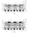
- FIG. 2is a diagrammatic sketch in a sectional view illustrating the structure of an example of a 2-stack MPM, generally at 20 , in which the z-interconnect is made by way of solder balls.
- a first package(which may be referred to as the “bottom” package) is similar to a standard BGA as shown in FIG. 1A (and similar reference numerals are employed to point to similar features of the bottom package in FIGS. 1A and 2 ).
- a second package(which may be referred to as the “top” package) is stacked on the bottom package and is similar in structure to the package of FIG. 1B (and similar reference numerals are employed to point to similar features of the top package in FIGS.
- the top package in FIG. 2includes a die 24 attached onto a substrate 22 having at least one metal layer.
- the top package substrate 22 shown by way of example in FIG. 2has two metal layers 221 , 223 , each patterned to provide appropriate circuitry and connected by way of vias 222 .
- the dieis conventionally attached to a surface of the substrate (the “upper” surface) using an adhesive, typically referred to as the die attach epoxy, shown at 23 in FIG. 2 .
- the dieis wire bonded onto wire bond sites on the upper metal layer of the substrate to establish electrical connections.
- the top package die 24 and wire bonds 26are encapsulated with a top package molding compound 27 .
- Solder balls 28are reflowed onto bonding pads located on the peripheral margin of the lower metal layer of the top package substrate to provide z-interconnection to the bottom package.
- Solder masks 225 , 227are patterned over the metal layers 221 , 223 to expose the underlying metal at bonding sites for electrical connection, for example the wire bond sites and bonding pads for bonding the wire bonds 26 and solder balls 28 .
- the z-interconnection in the MPM of FIG. 2is achieved by reflowing the solder balls 28 attached to peripheral bonding pads on the lower metal layer of the top package substrate onto peripheral bonding pads on the upper metal layer of the bottom BGA.
- This type of z-interconnectrequires that the upper and lower substrates be designed with matching pads for the interconnect balls. If one of the packages is exchanged for one in which the substrate has a different pad arrangement (different size or different design), then the substrate for the other package must be reconfigured accordingly. This leads to increased cost for manufacture of the MPM.
- the distance h between the top and bottom packagesmust be at least as great as the encapsulation height of the bottom package, which may be 0.25 mm or more, and typically is in a range between 0.5 mm and 1.5 mm.
- the solder balls 28must accordingly be of a sufficiently large diameter that when they are reflowed they make good contact with the bonding pads of the bottom BGA; that is, the solder ball 28 diameter must be greater than the encapsulation height.
- a larger ball diameterdictates a larger ball pitch that in turn limits the number of balls that can be fitted in the available space.
- the peripheral arrangement of the solder ballsforces the bottom BGA to be significantly larger than the mold cap of a standard BGA.
- the peripheral arrangement of the solder ballsincreases the overall package size (the size increases according to the number of ball rows and the ball pitch).
- the package body sizeis 1.7 mm larger than the die.
- the body sizecan be as much as about 2-3 mm larger than the mold cap.
- the top package in such a configurationmust be made of comparable size to the bottom one even though it may contain a small chip with many fewer interconnects. In this configuration the top package substrate must have at least 2 metal layers to facilitate the electrical connections.
- FIG. 3is a diagrammatic sketch in a sectional view illustrating the structure of an example of a known 2-stack flip chip MPM, shown generally at 30 .
- the bottom BGA flip chip packageincludes a substrate 32 having a patterned metal layer 31 onto which the die 34 is connected by flip chip bumps 36 , such as solder bumps, gold stud bumps or anisotropically conducting film or paste.
- the flip chip bumpsare affixed to a patterned array of bump pads on the active surface of the die and, as the active surface of the die faces downward in relation to an upward-facing patterned metal layer of the substrate, such an arrangement may be referred to as a “die down” flip chip package.
- a polymer underfill 33 between die and substrateprovides protection from ambient and adds mechanical integrity to the structure.
- Such a flip chip packagein which the substrate has a metal layer on only the upper surface, is connected to the underlying circuitry (such as a motherboard, not shown in the FIG.) by solder balls 38 connected to the metal layer through solder vias 35 .
- the top BGA in this configurationis similar to the bottom BGA, except that the top BGA has z-interconnect solder balls 338 connected (through solder vias 335 in the top substrate) to the metal layer 331 only at the periphery of the top substrate. Solder balls 338 are reflowed onto the metal layer 31 of the bottom substrate to provide the z-interconnect.
- the top BGA in this configurationincludes a substrate 332 having a patterned metal layer 331 onto which the top BGA die 334 is connected by flip chip bumps 336 . Between the top BGA die and substrate is a polymer underfill 333 .
- a structure as in FIG. 3is more appropriate for high electrical performance applications, but it has similar limitations to configurations of the type shown in of FIG. 2 . It presents an improvement over the FIG. 2 configuration in that the bottom BGA has no molding, allowing for use of smaller diameter (h) solder balls at the periphery of the top BGA for connection between the packages.
- this structureis more appropriate, for example, for modules containing stacks of identical memory chips having the same connections at the same locations to facilitate the z-interconnect. It is not appropriate for stacking packages that have different chips with connection points not located over one another in the stack. As in the configuration of FIG. 2 , the peripheral arrangement of solder balls limits the number of interconnects. Moreover, the packages must necessarily be of comparable size, and where the chip in one package is smaller than that in the other, the package having the smaller chip will be forced to a larger size, imposing a higher cost.
- FIG. 4is a diagrammatic sketch in a sectional view illustrating the structure of an example of a known 2-stack folded flexible substrate MPM, shown generally at 40 .
- the bottom package in the configuration of FIG. 4has a 2-metal layer flexible substrate onto which the die is bonded via small beams to the first metal layer of the substrate.
- the second metal layer of the bottom package substratecarries the solder balls for connection to the underlying circuitry, such as a motherboard (not shown).
- the substrateis large enough to be folded over the top of the package, thus bringing the electrical interconnect lines upward where they are available for connection to the top package (an example of which is described below) by way of an array of solder balls on the top package.
- the space around the die and between the die and folded-over substrateis encapsulated 47 to provide protection and rigidity.
- the two-metal layer bottom package substrate 42includes a first metal layer 141 and a second metal layer 143 , each patterned to provide appropriate circuitry and connected by way of vias 142 .
- a part of the first metal layer, over a part of the bottom substrate,is processed (for example, using an array of punches) to present an array of cantilever beams or tabs 46 arranged to correspond to an array of interconnect pads on the active surface of the bottom package die 44 .
- the first metal layer 141faces upwardly.
- the dieis aligned, active surface downward, over the die attach part of the substrate, and the cantilevers and the corresponding interconnect pads are joined, typically for example by a “thermosonic” process employing a combination of pressure, heat, and ultrasonic energy to complete the electrical connections.
- the die 44is affixed using an adhesive 43 , typically a die attach epoxy, onto the die attach part of the flexible substrate 42 .
- a second metal layer 143 of the bottom package substrate 42faces downwardly in the die attach part of the substrate.
- Solder balls 48are reflowed onto bonding pads located on an array on the downward-facing part of the second metal layer 143 to provide for interconnection of the MPM to underlying circuitry (not shown).
- a solder mask 147is patterned over the second metal layer 143 to expose the underlying metal as bonding sites for electrical connection, including the bond pads for connection with the underlying circuitry by way of solder balls 48 , and the bond pads for connection with the top package by way of solder balls 18 , as described below.
- the top packageis generally similar to the BGA of FIG. 1 , in which the die is wire bonded onto wire bond sites on the upper metal layer of the substrate to establish electrical connections.
- the top package die 14is attached onto a substrate 12 having (in this example) two metal layers 121 , 123 , each patterned to provide appropriate circuitry and connected by way of vias 122 .
- the dieis conventionally attached to the upper surface of the top package substrate using an adhesive 13 , typically a die attach epoxy.
- the die 14 and the wire bonds 16are encapsulated with a molding compound 17 that provides protection from ambient and from mechanical stress to facilitate handling operations, and provides a surface for marking for identification.
- Solder balls 18are reflowed onto bonding pads 143 on the upward-facing metal layer of the folded-over bottom package substrate to provide z-interconnection between the top and the bottom packages.
- An advantage of a structure as in FIG. 4is that the folded-over substrate provides sufficient area on the upward-facing surface of the folded-over bottom package substrate to accommodate a full array of solder balls in the top package and to accommodate more complex interconnect between the two packages. It also provides for a small package footprint.
- a primary disadvantage of this configurationis the high cost of the substrate and the unavailability of folding technology and equipment.
- a lack of folding technology and equipmentmakes manufacture of the 2-stack folded flexible substrate MPM configuration more complex and more costly.
- the two substratesmust be designed such that the pads match for the interconnect balls. If one of the packages is exchanged for one in which the substrate has a different pad arrangement (different size or different design), then the substrate for the other package must be reconfigured accordingly. This leads to increased cost for manufacture of the MPM.
- all the interconnects from the top to the bottom packagemust be routed through the folded portion of the flex substrate at one edge of the package. This increases the routing density and increases the length of the routing traces, resulting in higher inductance and lower electrical performance of the MPM.
- a common feature of all these stacked package configurationsis that they enable pretesting of each package, and provide for production MPMs with higher final test yields.
- This inventionis directed to multi-package modules.
- z-interconnection between the stacked packages in the MPMis wire bond based, and an upper package is inverted.
- the inventionfeatures various configurations of various stacked packages, including a bottom (lower) package and at least one inverted top (upper) package, and methods for stacking and interconnecting the various packages by wire-bonding based z-interconnection.
- the package stackcan include any of a variety of BGA and/or any of a variety of Land Grid Array (“LGA”) packages and/or any of a variety of bump chip carrier packages; the package stack can include wire bonded and/or flip chip packages; the package stack can include a thermal enhancement feature enabled by one or more heat spreaders in or on the stack; the package stack can include one or more packages having a flip chip bonded die bonded either to the top or to the bottom of the BGA or LGA; the package stack can include one or more BGA and/or LGA having more than one die in the package stacked or side by side; the stack can include electromagnetic shield for one or more of the packages; and the stack can include any substrate, laminate or build-up or flexible or ceramic, provided that the z-interconnect pads are made available for bonding on the periphery of the packages.
- LGALand Grid Array
- the inventionfeatures a multi-package module having stacked lower and upper packages, each package including a die attached to a substrate, in which the upper package is inverted and the upper and lower substrates are interconnected by wire bonding.
- the inventionprovides for excellent manufacturability, high design flexibility, and low cost to produce a stacked package module having a low profile and a small footprint.
- the wire bond z-interconnectis well established in the industry; it is the lowest cost interconnect technique and it is directly applicable, without significant modification, to the stacked multi-package modules of the invention. It provides design flexibility to the relative size of the BGA to LGA that can be bridged by wire length. Using available techniques and equipment the wire in a wire bond can be as short as 0.5 mm or as long as 5 mm.
- the arrangement of the z-interconnect padscan be implemented through either or both BGA and LGA substrate designs.
- z-interconnectcan be formed between pads that are not precisely aligned over one another, by employing so-called “out of sequence bonding” that is in current use in the industry.
- the wire bonding pitchis the finest available technology in the industry at 50 microns currently, and projected to go to 25 microns. This is finer than any other interconnect including flip chip (around 200 microns) or solder balls (at about 500 microns), and therefore provides for more interconnects between packages (z-interconnects) in the same available space.
- Wire bonding using a wire bonding machineprovides design flexibility for interconnecting pads, because the connections are programmed in the wire bonder, avoiding the need for hard tooling substrates to match each other and connect with solder balls.
- the wire bondingcan be reconfigured to accommodate the differences by program changes. If the top package must be smaller than the bottom, wire bonding can accommodate size differences at least up to 9 mm. This allows for use of the smallest package needed to accommodate the chip size, and thus optimizes the total cost of the MPM.
- Wire bondingcan interconnect pads that are “out of sequence,” that is, not situated in the desired order and not precisely above each other in either package, so long as they are not too far apart. Where necessary, the pads can be appropriately routed to a location close enough for wire bonding. This flexibility allows stacking of packages that do not have the “desired” order or location of interconnect pads. As the chip technology advances usually the chip size shrinks and design variants are developed with either more connections or some connections with different order. The bonding flexibility provided by wire bonding allows the user to maintain the same package size but vary the substrate design. This results in lower cost and faster time to market, both critical for new products.
- the BGAs and LGAs, including chip scale packagesare standard in the industry, providing the lowest cost and the widest availability. This provides significant flexibility in selecting the packages to be stacked and, therefore, in the kinds of functions that can be integrated into the MPM.
- a typical BGA thicknessis 1.0 mm and LGA thickness is 0.8 mm.
- the stacking of an inverted LGA on top of a BGA according to the inventioncan be completed using an adhesive having a finished thickness in the range 10-50 microns.
- This structureprovides for a lower profile MPM compared to conventional constructs that employ solder balls for the z-interconnect.
- the footprint of the MPM according to the inventionis determined by the maximum chip size of the stack.
- a typical minimum footprint for the BGA or LGAis 1.7 mm larger than the die size.
- the wire bond z-interconnectgenerally requires that the top LGA be minimally smaller than the bottom BGA, by about 0.1 mm to 0.8 mm, to accommodate the wires without shorting to the substrate metal edges.
- top packagemust be significantly smaller than the bottom package, wire bonding can accommodate size differences at least up to 9 mm. This allows for minimizing the size of the package needed to accommodate the chip size, and thus for optimizing the total cost of the MPM. Both the footprint and the thickness of the stacked package MPM according to the invention fall within accepted ranges for most applications.
- the multi-package moduleincludes three or more packages, affixed serially to form a stack.
- the inventionfeatures a multi-package module having stacked first (“bottom”) and second (“top”) packages, the bottom package being a BGA package and the top package being an LGA package, each package including a first die attached to a substrate, in which the LGA package substrate and the BGA package substrate are interconnected by wire bonding, and in which the LGA package substrate is inverted so that the LGA substrate surface to which its die is attached is downward.
- the second packageis an LGA package, and in some embodiments the second package is a saw-singulated package, and may be a chip scale package. In some embodiments the second package is a bump chip carrier package.
- the inventionfeatures a multi-package module having stacked first (“bottom”) and second (“top”) packages, the bottom package being a BGA package and the top package being an inverted LGA package, in which the inverted LGA package substrate and the BGA package substrate are interconnected by wire bonding, and in which at least one of the packages is provided with a heat spreader.
- a heat spreadermay additionally be configured to serve as an electrical shield, particularly for example where the heat spreader is situated over a lower die, that is, between a bottom and a top package in the stack.
- the heat spreaderis affixed to the upward surface of a topmost LGA package, and in such embodiments the heat spreader is exposed to ambient at the topmost surface of the MPM.
- the inventionfeatures a multi-package module having stacked first (“bottom”) and second (“top”) packages, the bottom package being a flip-chip BGA package having a flip-chip in a “die-up” configuration and the top package being an inverted LGA package, in which the top substrate and the bottom package are interconnected by wire bonding.
- the top packageis a stacked die package; in some embodiments the adjacent stacked die in the stacked die package can be separated by spacers.
- the die on the BGA packageis at least partially enclosed within an electrical shield (a “can” or “cage) affixed to the under surface of the BGA substrate.
- the bottom package substrateincludes an embedded ground plane, the ground plane being configured to serve also for heat dissipation and as an electrical shield.
- a plurality of inverted second (“top”) packagesis affixed over a plurality of die attach regions on the upper surface of the first (“bottom”) package substrate.
- the inventionfeatures a multi-package module having stacked first (“bottom”) and second (“top”) packages, the bottom package being a flip-chip BGA package having a flip-chip in a “die-down” configuration and the top package being an inverted LGA package, in which the top substrate and the bottom package are interconnected by wire bonding.
- the flip-chip die on the bottom packageis provided with an electrical shield.
- the inventionfeatures a multi-package module having stacked first (“bottom”) and second (“top”) packages, the bottom package being a BGA package and the top package being an inverted LGA package, in which the inverted LGA package substrate and the BGA package substrate are interconnected by wire bonding, and in which either the top LGA package or the bottom BGA package is a stacked die package, that is, the package includes a stack of two or more die connected to a surface of the substrate; or in which both packages are stacked die packages.
- the top LGA packagemay include a stack of two or more die affixed to, and connected (as for example by wire bonding) to the upside of the LGA substrate (oriented downward in the inverted LGA package).
- the inventionfeatures a multi-package module having stacked bottom and top packages, the bottom package being a BGA package and the top package being an inverted LGA package, in which an additional die is attached to the bottom surface of the LGA substrate (oriented upward in the inverted LGA package), that is, on the LGA substrate surface opposite the surface to which a first die is attached.
- an additional dieis attached to the bottom surface of the LGA substrate (oriented upward in the inverted LGA package), that is, on the LGA substrate surface opposite the surface to which a first die is attached.
- the interconnect of the additional die on the LGA substrateis by wire bonding to the LGA substrate; in some embodiments the interconnect of the additional die on the LGA substrate is a is flip chip interconnect.
- the inventionfeatures a multi-package module having stacked bottom and top packages, the bottom package being a BGA package and the top package being an inverted LGA package, in which a third package is affixed upon the top LGA package.
- the third packageis a second inverted LGA package, and the z-interconnect between the third package is by wire bonding; in some embodiments the third package is not inverted, and the z-interconnect with the inverted LGA package is by solder balls between ball pads on the lower surface (downward surface) of the third package and ball pads on the lower surface (that is, the upward surface) of the inverted LGA package.
- the inventionfeatures a multi-package module having stacked first (“bottom”) and second (“top”) packages, the bottom package being a BGA package and the top package being a bump chip carrier package, in which the bump chip carrier package substrate and the BGA package substrate are interconnected by wire bonding, and in which the bump chip carrier package is inverted so that the substrate surface to which its die is attached is oriented downward.
- the inventionfeatures a method for making a multi-package module, by providing a first (“bottom”) molded package including a bottom package substrate and a die, dispensing adhesive onto an upper surface of the bottom molded package, placing a second (“top”) package including a top package substrate and a die in an inverted orientation such that an upper (downward) surface of the top package substrate contacts the adhesive on the upper surface of the bottom package, curing the adhesive, and forming z-interconnects between the top and bottom substrates.
- the multi-package moduleincludes a third or additional packages, and the method includes affixing the third or additional packages serially to form a stack.
- the inventionfeatures a method for making a multi-package module including an inverted top package, which may be an LGA package or a bump chip carrier (“BCC”) package stacked over a bottom BGA package, in which the top and bottom packages are electrically interconnected by wire bonding.
- an inverted top packagewhich may be an LGA package or a bump chip carrier (“BCC”) package stacked over a bottom BGA package, in which the top and bottom packages are electrically interconnected by wire bonding.
- BCCbump chip carrier
- a BGA packageis provided, usually in an unsingulated strip of molded BGA packages; preferably the BGA packages in the strip are tested for performance and reliability and packages identified as “good” are subjected to subsequent treatment; adhesive is dispensed over the upper surface of the molding on “good” BGA packages; a singulated (for example, saw-singulated) molded land grid array package or bump chip carrier package is provided; preferably the LGA package or BCC package is tested and identified as “good”; the “good” LGA or BCC package is inverted and placed onto the adhesive over the molding on the “good” BGA package, and the adhesive is cured; optionally and preferably a plasma clean operation is performed followed by formation of wire bond z-interconnections between the stacked top and bottom packages; optionally and preferably an additional plasma clean may be performed, followed by the formation of the MPM molding. Further steps include attachment of second-level interconnect solder balls to the underside of the module; testing and singulation of the completed module from the strip, for
- the methodincludes steps for providing the multi-package module with a heat spreader.
- a similar processis performed, with additional steps interposed installation of supported heat spreader by a “drop-in” mold operation, or for installation of a simple planar heat spreader by a drop-in mold operation; or by applying adhesive onto an upper surface of the top package molding or onto an upper surface of a spacer upon the top package, and affixing the planar heat spreader onto the adhesive.
- the inventionfeatures a method for making a multi-package module including an inverted top package stacked over a die-down flip chip BGA bottom package, in which the top and bottom packages are electrically interconnected by wire bonding.
- a die-down flip chip BGA bottom packageoptionally molded, is provided, usually in unsingulated strip of die-down flip chip ball grid array bottom packages; preferably the BGA packages in the strip are tested for performance and reliability and packages identified as “good” are subjected to subsequent treatment; adhesive is dispensed onto the upper surface (back side) of the die on “good” BGA packages; singulated top (e.g., land grid array or bump chip carrier) packages, optionally molded, are provided; preferably the LGA or BCC package is tested and identified as “good”; the “good” LGA or BCC package is inverted and placed onto the adhesive over the shield, and the adhesive is cured; optionally and preferably a plasma clean operation is performed followed by formation of wire bond z-interconnections between
- the inventionfeatures a method for making a multi-package module including an inverted top package stacked over a die-down flip chip BGA bottom package, in which the top and bottom packages are electrically interconnected by wire bonding, and in which the bottom package is provided with an electrical shield.
- a processis performed similar to that described above for the unshielded bottom flip chip bottom package, with an additional step interposed for installation of the shield over the bottom package flip chip die.
- a die-down flip chip BGA bottom package, optionally molded,is provided, usually in unsingulated strip of die-down flip chip ball grid array bottom packages; preferably the BGA packages in the strip are tested for performance and reliability and packages identified as “good” are subjected to subsequent treatment; an electrical shield is affixed over the die on “good” bottom BGA packages; adhesive is dispensed onto the upper surface of the shield on “good” BGA packages; singulated top (e.g., land grid array or bump chip carrier) packages, optionally molded, are provided; preferably the LGA or BCC package is tested and identified as “good”; the “good” LGA or BCC package is inverted and placed onto the adhesive over the shield, and the adhesive is cured; optionally and preferably a plasma clean operation is performed followed by formation of wire bond z-interconnections between the stacked top and bottom packages; optionally and preferably an additional plasma clean may be performed, followed by the formation of the MPM molding. Further steps include attachment of second-level interconnect solder balls to
- the inventionfeatures a method for making a multi-package module including an inverted top package stacked over a die-up flip chip BGA bottom package, in which the top and bottom packages are electrically interconnected by wire bonding.
- a die-up flip chip ball grid array packageusually not molded, is provided, usually as an unsingulated strip of die-up flip chip ball grid array packages; preferably the BGA packages in the strip are tested for performance and reliability and packages identified as “good” are subjected to subsequent treatment; adhesive is dispensed over the upper surface of the substrate on “good” BGA packages; a second package is provided, which may in some embodiments be a stacked die package, optionally and usually molded; preferably the second package is tested and identified as “good”; the “good” second package is inverted and placed onto the adhesive over the BGA substrate, and the adhesive is cured; optionally and preferably a plasma clean operation is performed followed by formation of wire bond z-interconnections between the stacked top and bottom packages; optionally
- the inventionfeatures a method for making a multi-package module including an inverted top package stacked over a stacked die bottom package, in which the top and bottom packages are electrically interconnected by wire bonding.
- a stacked die BGA packageusually molded, is provided, usually as an unsingulated strip of stacked die ball grid array packages is provided; preferably the BGA packages in the strip are tested for performance and reliability and packages identified as “good” are subjected to subsequent treatment; adhesive is dispensed over the upper surface of the “good” stacked die BGA package, usually on the generally planar upper surface of the package molding; a singulated second package is provided, usually molded, which may optionally be a stacked die package; preferably the second package is tested and identified as “good”; the “good” second package is inverted and placed onto the adhesive over the upper surface of the BGA, and the adhesive is cured; optionally and preferably a plasma clean operation is performed followed by formation of wire bond z-interconnections between the stacked
- two or more first molded packagesare provided in an unsingulated strip, and assembly of the two or more modules proceeds on the strip, and singulation of the two or more modules is carried out after assembly has been completed.
- the electrical connections between the stacked packagesemploys conventional wire bonding to form the z-interconnect between the inverted top package substrate and a bottom package substrate in the stack.
- Particular advantagesinclude the use of established manufacturing infrastructure, low production cost, design flexibility, and a thin package product.
- the wire bonding processmay be carried out in either a “forward” or in a “reverse” manner.
- the z-interconnect wire bondingcan be carried out, in the various package and module configurations, by drawing the wire to a conductive pad on the first package substrate from a bump formed on a conductive pad on the second package substrate; or, by drawing the wire to a conductive pad on the second package substrate from a bump formed on a conductive pad on the first package substrate.
- the inventionprovides for assembly of more than one semiconductor in a thin and minimal footprint package at the lowest cost and highest final test yield. Furthermore some stack configurations according to the invention allow for high thermal performance, high electrical performance or electrical isolation of an RF component from a digital one. Other stack configurations provide a very thin structure appropriate for handheld or consumer products. All provide for a method for assembly that allows individual testing of the stacked packages to maximize the final yield of the module.
- Additional process stepswill be employed to complete the multi-package module according to the invention. For example, it may be preferred not to attach solder balls for connection of the lowermost package in the stack to the motherboard until the final step before singulation of the MPMs. And, for example, a plasma clean may be performed at any of a variety of points in the process, such as following adhesive cure and prior to encapsulation, and such as prior to and/or following z-interconnect wire bonding.
- the individual packagescan be provided as strips of several packages, connected in a row for ease of handling during manufacture, to be singulated following completion of process steps.
- a strip of first packages of a selected typecan be kept nonsingulated, and the package stacks can be formed on the strip by affixing singulated packages and forming the wire bonded z-interconnects serially until the process of forming the modules is complete, and then singulating the modules.
- MPM according to the inventioncan be used for building computers, telecommunications equipment, and consumer and industrial electronics devices.
- FIG. 1Ais a diagrammatic sketch in a sectional view thru a conventional ball grid array semiconductor package.
- FIG. 1Bis a diagrammatic sketch in a sectional view thru a conventional ball grid array semiconductor package having a molding cap over the entire substrate surface, as for example a chip scale package.
- FIG. 2is a diagrammatic sketch in a sectional view thru a conventional multi-package module having solder ball z-interconnection between stacked ball grid array semiconductor packages.
- FIG. 3is a diagrammatic sketch in a sectional view thru a conventional flip chip multi-package module having solder ball z-interconnection between stacked flip chip semiconductor packages.
- FIG. 4is a diagrammatic sketch in a sectional view thru a conventional multi-package module having a folded flexible substrate and solder ball z-interconnection between stacked semiconductor packages.
- FIG. 5Ais a diagrammatic sketch in a sectional view thru an embodiment of a multi-package module having wire bond z-interconnection between stacked lower BGA and inverted upper LGA semiconductor packages according to an aspect of the invention.
- FIG. 5Bis a sketch in a plan view showing bottom BGA z-interconnect bond pads in an arrangement suitable for use in an embodiment of the invention as shown in FIG. 5A .
- FIG. 5Cis a sketch in a plan view showing top LGA z-interconnect bond pads in an arrangement suitable for use in an embodiment of the invention as shown in FIG. 5A .
- FIG. 5Dis a diagrammatic sketch in a sectional view thru an embodiment of a multi-package module having wire bond z-interconnection between stacked lower BGA and inverted upper LGA semiconductor packages, having a heatspreader over the inverted LGA, according to an aspect of the invention.
- FIG. 6Ais a diagrammatic sketch in a sectional view thru an embodiment of a multi-package module having wire bond z-interconnection between stacked lower BGA and inverted upper LGA semiconductor packages, and having an electrical shield/heatspreader over the lower BGA and between the lower BGA and the inverted upper LGA, according to a further aspect of the invention.
- FIG. 6Bis a diagrammatic sketch in a sectional view thru an embodiment of a multi-package module having wire bond z-interconnection between stacked lower BGA and inverted upper LGA semiconductor packages, and having an electrical shield/heatspreader over the lower BGA and between the lower BGA and the inverted upper LGA as in FIG. 6A , and further having a heatspreader over the inverted LGA, according to a further aspect of the invention.
- FIG. 7Ais a diagrammatic sketch in a sectional view thru an embodiment of a multi-package module having wire bond z-interconnection between stacked bottom flip chip (die down) BGA and inverted top LGA semiconductor packages according to a further aspect of the invention.
- FIG. 7Bis a diagrammatic sketch in a sectional view thru an embodiment of a multi-package module having wire bond z-interconnection between stacked bottom flip chip (die down) BGA and inverted top LGA semiconductor packages according to a further aspect of the invention, the bottom package being provided with an electromagnetic shield/heat spreader.
- FIG. 7Cis a diagrammatic sketch in a sectional view thru an embodiment of a multi-package module having wire bond z-interconnection between stacked lower flip chip (die down) BGA and inverted upper LGA semiconductor packages according to a further aspect of the invention, the bottom package being provided with an electromagnetic shield/heat spreader, and the module being further provided with a top heat spreader.
- FIG. 8Ais a diagrammatic sketch in a sectional view thru an embodiment of a multi-package module having wire bond z-interconnection between stacked bottom flip chip (die up) BGA and inverted top LGA semiconductor packages according to a further aspect of the invention.
- FIG. 8Bis a diagrammatic sketch in a sectional view thru an embodiment of a multi-package module having wire bond z-interconnection between stacked bottom flip chip (die up) BGA and inverted top LGA semiconductor packages according to a further aspect of the invention, the bottom package being provided with an electromagnetic shield/heat spreader.
- FIG. 8Cis a diagrammatic sketch in a sectional view thru an embodiment of a multi-package module having wire bond z-interconnection between stacked lower flip chip (die up) BGA and inverted upper LGA semiconductor packages according to a further aspect of the invention, the bottom package being provided with an electromagnetic shield/heat spreader, and the module being further provided with a top heat spreader.
- FIG. 8Dis a diagrammatic sketch in a sectional view thru an embodiment of a multi-package module having wire bond z-interconnection between stacked lower flip chip (die up) BGA and multiple inverted upper LGA semiconductor packages according to a further aspect of the invention.
- FIG. 9Ais a diagrammatic sketch in a sectional view thru an embodiment of a multi-package module having wire bond z-interconnection between stacked lower BGA and inverted upper LGA semiconductor packages according to a further aspect of the invention, in which each of the inverted upper LGA and lower BGA has stacked die wire-bonded to the substrate.
- FIG. 9Bis a diagrammatic sketch in a sectional view thru an embodiment of a multi-package module having wire bond z-interconnection between stacked lower BGA and inverted upper LGA semiconductor packages according to a further aspect of the invention, in which each of the inverted upper LGA and lower BGA has stacked die wire-bonded to the substrate, and in which the module is provided with a top heat spreader.
- FIG. 10Ais a diagrammatic sketch in a sectional view thru an embodiment of a multi-package module having wire bond z-interconnection between stacked bottom BGA and inverted top semiconductor packages according to a further aspect of the invention, in which the top package is a BCC package.
- FIG. 10Bis a diagrammatic sketch in a sectional view thru an embodiment of a multi-package module having wire bond z-interconnection between stacked bottom BGA and inverted top semiconductor packages according to a further aspect of the invention, in which the top package is a BCC package having an additional die stacked on the BCC die.
- FIG. 11Ais a diagrammatic sketch in a sectional view thru an embodiment of a multi-package module having wire bond z-interconnection between stacked bottom BGA and inverted top LGA semiconductor packages according to a further aspect of the invention, in which the die in the bottom BGA is wire-bonded to the substrate, and in which a first die on the downward facing surface of the inverted top LGA is wire-bonded to the LGA substrate and a second die on the opposite (upward facing) surface of the top LGA is flip-chip interconnected to the LGA substrate.
- FIG. 11Bis a diagrammatic sketch in a sectional view thru an embodiment of a multi-package module having wire bond z-interconnection between stacked bottom BGA and inverted top LGA semiconductor packages according to a further aspect of the invention, in which the die in the bottom BGA is wire-bonded to the substrate, and in which both a first die on the downward facing surface of the inverted top LGA and a second die on the upward facing surface of the bottom package substrate are wire-bonded to the top LGA substrate.
- FIG. 11Cis a diagrammatic sketch in a sectional view thru an embodiment of a multi-package module having wire bond z-interconnection between stacked bottom BGA and inverted top LGA semiconductor packages according to a further aspect of the invention, in which a third package is stacked over the inverted top LGA package, and is wire bonded thereto.
- FIG. 11Dis a diagrammatic sketch in a sectional view thru an embodiment of a multi-package module having wire bond z-interconnection between stacked bottom BGA and inverted top LGA semiconductor packages according to a further aspect of the invention, in which a third package is stacked over the inverted top LGA package, and is connected by solder balls thereto.
- FIG. 12is a flow diagram showing a process for assembly of a multi-package module according to the invention.
- FIG. 13is a flow diagram showing a process for assembly of a multi-package module according to the invention, in which the bottom package is provided with a heat shield/heat spreader.
- FIG. 14is a flow diagram showing a process for assembly of a multi-package module according to the invention, in which the bottom package is provided with a heat shield/heat spreader, and the module is further provided with a top heat spreader.
- FIG. 15is a flow diagram showing a process for assembly of a multi-package module according to the invention, in which the bottom package is a flip chip package in a die-down configuration.
- FIG. 16is a flow diagram showing a process for assembly of a multi-package module according to the invention, in which the bottom package is a flip chip package in a die-down configuration, and the package is provided with a top heat spreader.
- FIG. 17is a flow diagram showing a process for assembly of a multi-package module according to the invention, in which the bottom package is a flip chip package in a die-up configuration.
- FIG. 18is a flow diagram showing a process for assembly of a multi-package module according to the invention, in which the top and bottom packages are stacked die packages.
- FIG. 5Athere is shown in a diagrammatic sectional view generally at 50 an embodiment of a multi-package module, including stacked first (“bottom”) and second (“top”) packages, in which the top package is inverted, and the stacked packages are interconnected by wire bonding, according to an aspect of the invention.
- the bottom package 400is a conventional BGA package such as that shown in FIG. 1A .
- the bottom package 400includes a die 414 attached onto a bottom package substrate 412 having at least one metal layer.
- any of various substrate typesmay be used, including for example: a laminate with 2-6 metal layers, or a build up substrate with 4-8 metal layers, or a flexible polyimide tape with 1-2 metal layers, or a ceramic multilayer substrate.
- the bottom package substrate 412 shown by way of example in FIG. 5Ahas two metal layers 421 , 423 , each patterned to provide appropriate circuitry and connected by way of vias 422 .
- the dieis conventionally attached to a surface of the substrate using an adhesive, typically referred to as the die attach epoxy, shown at 413 in FIG. 5A and, in the configuration in FIG. 5A , the surface of the substrate onto which the die is attached may be referred to as the “upper” surface, and the metal layer on that surface may be referred to as the “upper” metal layer, although the die attach surface need not have any particular orientation in use.
- the dieis wire bonded onto wire bond sites on the upper metal layer of the substrate to establish electrical connections.
- the die 414 and the wire bonds 416are encapsulated with a molding compound 417 that provides protection from ambient and from mechanical stress to facilitate handling operations, and provides a bottom package upper surface 419 onto which a second (“top”) package can be stacked.
- the connections to the dieare exposed at the periphery of the package with pads on the top metal layer of the substrate and available for connecting with wire bonds as described in more detail below with reference to FIGS. 5B and 5C . These pads easily fit within the space available between the lower BGA mold cap and the edge of the package, without increasing the overall footprint of the BGA.
- solder balls 418are reflowed onto bonding pads on the lower metal layer of the substrate to provide interconnection to underlying circuitry of, for example, a motherboard (not shown in the FIGS.) of a final product, such as a computer.
- Solder masks 415 , 427are patterned over the metal layers 421 , 423 to expose the underlying metal at bonding sites for electrical connection, for example the wire bond sites and bonding pads for bonding the wire bonds 416 and solder balls 418 .
- the top package 500is a land grid array (“LGA”) package which may be a saw singulated LGA package, as shown for example in FIG. 1B , and may be a chip scale package; but here the top package has no solder balls mounted on bonding pads of the lower surface of the substrate.
- LGAland grid array
- the top package 500includes a die 514 attached onto a top package substrate 512 having at least one metal layer. Any of various substrate types may be used; the top package substrate 512 shown by way of example in FIG. 5A has two metal layers 521 , 523 , each patterned to provide appropriate circuitry and connected by way of vias 522 .
- the dieis conventionally attached to a surface of the substrate using an adhesive, typically referred to as the die attach epoxy, shown at 513 in FIG. 5A .
- the die attach epoxytypically referred to as the die attach epoxy, shown at 513 in FIG. 5A .
- the dieis referred to as being attached to an upper surface of the package substrate, it being appreciated that the package need not have any particular orientation in use.
- the top packageis inverted, that is to say, it is attached upside downward and downside upward.
- the surface of the upper LGA to which the first die is attachedwhich would customarily be termed the upper surface or upper side of the LGA substrate, is referred to in the text herein as the downward or downward facing surface of the inverted LGA; and the opposite surface, which would customarily be termed the lower surface or lower side, is referred to in the text herein as the upward or upward facing surface.
- the surface of the top package substrate onto which the die is attachedfaces toward the bottom package, and, accordingly the “upper” surface of the top package, to which the die is affixed, is here referred to as the “downward facing” surface of the top package substrate, it being appreciated again that the module need not have any particular orientation in use. That is to say, once the top package has been inverted in the module according to the invention, for purposes of description the surface of the top package substrate having the “upper” metal layer 521 is said to be “downward facing”, and the surface of the top package substrate having the “lower” metal layer 523 is said to be “upward facing”.
- the dieis wire bonded onto wire bond sites on the upper metal layer of the top package substrate to establish electrical connections.
- the die 514 and the wire bonds 516are encapsulated with a molding compound 517 that provides protection from ambient and from mechanical stress to facilitate handling operations, and has a top package upper surface 519 .
- the top package 500is inverted (so that the surface 519 is “downward facing”, and is stacked over the bottom package 400 and affixed there using an adhesive 513 .
- Solder masks 515 , 527are patterned over the metal layers 521 , 523 to expose the underlying metal at bonding sites for electrical connection, for example the wire bond sites for bonding the wire bonds 516 .
- the z-interconnect between the stacked top package 500 and bottom package 400is made by way of wire bonds 518 extending outwardly from the stacked top package 500 and connecting traces on the upward facing metal layer (the “lower” metal layer 523 ) of the top package substrate with traces on the upper metal layer 421 of the bottom package substrate. At one end each wire bond 518 is electrically connected to upward facing surfaces of pads on the lower metal layer 523 of the top package substrate 512 , and at the other end each wire bond is connected to upper surfaces of pads on the upper metal layer 421 of the bottom package substrate 412 .
- the wire bondsmay be formed by any wire bonding technique, well known in the art, such as is described, for example, in U.S. Pat. No.
- the package-to-package z-interconnect wire bondsare shown by way of example in FIG. 5A as having been made by forming a bead or bump on the upper surface of a pad on the upper metal layer of the top substrate, and then drawing the wire downward toward and fusing it onto, a pad on the upper metal layer of the bottom substrate.
- the wire bondscan be made in the inverse direction, that is, by forming a bead or bump on the upper surface of a pad on the upper metal layer of the bottom substrate, and then drawing the wire upward toward and fusing it onto, a pad on the upper metal layer of the top substrate.
- selection of a wire bonding strategy for the package-to-package z-interconnectionwill be determined according to the geometric arrangements of the margins of the stacked substrates and of the bonding surfaces on them.
- the top LGA packagemay be either array molded and saw singulated (giving vertical walls at the edges, as shown for example in FIG. 1B and as the upper LGA in FIG. 2 , or cavity molded and punch singulated.
- the top packagehas bond pads connected to the die (through vias to the die attach side of the substrate) and situated at the periphery of the package on the substrate surface opposite the surface on which the die is attached, that is, on the “lower” (upward-facing) side of the top package substrate, as described in further detail below with reference to FIG. 5C .
- the structure according to the inventionallows for pre-testing of both the BGA and LGA before assembly into the multi-package module, to permit rejection of nonconforming packages prior to assembly, and thereby to assure high final module test yields.
- the z-interconnect pads on the respective package substratesare arranged on upward facing metal layers near the margins of the package substrates.
- the location and order of the z-interconnect padsare generally arranged so that the z-interconnect pads on the top package substrate approximately overlie the corresponding z-interconnect pads on the bottom package when the packages are stacked.
- the top package 500has a smaller substrate footprint than that of the bottom package 400 , to allow clearance for the wire bonds without electrical shorting to the edges of the metal layers of the substrates.
- a module encapsulation 507is formed, to enclose and protect the z-interconnect wire bonds and to provide mechanical integrity to the completed module.
- the moduleincludes molded packages within the module molding. As shown by way of example in FIG. 5A , the module may itself be saw-singulated; alternatively, the module may be individually molded rather than saw-singulated.
- top package z-interconnect pads 524are formed by patterning regions of the lower metal layer peripherally situated on the “lower” surface 525 of the top package substrate 512 .
- the “lower” substrate surface 525becomes the upward-facing surface of the top package substrate, and the top package z-interconnect pads 524 are, accordingly, also upward-facing in the module.
- the more centrally situated ball attach pads on the upward-facing side of the top package substrateare not necessary for z-interconnection and may be lacking in certain embodiments, depending upon the design of the top package. They are omitted, for illustrative purposes, from FIG. 5C .
- the ball attach pads on the upward-facing side of the inverted top package substratemay be employed to facilitate testing of the LGA using a conventional test socket.
- Such testing of the LGAcan be carried out prior to attaching the top LGA package into the bottom package, to ensure that only top LGAs testing as “good” are stacked over the bottom BGA packages (which may also be tested and identified as “good”).
- testing of the LGAcan be carried out following inversion of the LGA and attachment as a top package, but prior to formation of the overall module molding, or prior to z-interconnect wire-bonding. Testing, facilitated according to the constructs of the invention, at any of various stages in manufacture, can significantly reduce the likelihood of further processing of components that do not meet specifications.
- bottom package z-interconnect pads 424are formed by patterning regions of the upper metal layer situated at the margin 401 on the upper surface 425 of the bottom package substrate 412 .
- the margin 401extends beyond the footprint 426 of the stacked and overlying top package, defined by the edge 511 of the top package substrate 512 .
- the width of the margin 401can be less about 1 mm, and, in order to provide adequate clearance for the wire bonding the width of the margin 401 may preferably be greater than about 0.2 mm. Nominally in some embodiments the margin 401 is about 0.5 mm. Where the module is saw-singulated, the margin constitutes approximately the clearance between the edge of the top package substrate and the side of the module molding.
- the clearance between the z-interconnect wire bonds 518 and the upper surface of the module moldingmay preferably be about 75 ⁇ m or greater, to avoid impact between the molding machinery and the wire loops during molding formation; and the molding thickness over the upward-facing surface of the top package may preferably be greater than about 150 ⁇ m, to avoid formation of voids in the module molding.
- the wire loop height in practicemay be as little as about 75 ⁇ m and, accordingly, a molding thickness of as little as about 150 ⁇ m can be achieved in such embodiments.
- a greater mold heightwill be required where forward wire bonding is employed, as the wire loop height over a ball (or bump) as more usually about 125 ⁇ m or greater using currently available wire bonding techniques forming wire having about 1 mil thickness.
- z-interconnection between the top and bottom packages according to the inventionis made by wire bond between (either bond-up or bond-down) the top package interconnect pads 524 in the margin 501 of the top package substrate and the bottom package interconnect pads 424 in the margin 401 of the bottom package substrate.
- the multipackage module structureis protected by formation of a module encapsulant 507 , and solder balls 418 are reflowed onto exposed solder ball pads on the lower metal layer of the bottom package substrate, for connection to underlying circuitry, such as a motherboard (not shown in the FIGS.).
- the multi-package module of the inventioncan be employed in any of a diverse variety of applications, such as, for example, computers, portable communications devices, consumer products.
- a heat spreadermay be provided over the top package.
- the top heat spreaderis formed of a thermally conductive material having at least the more central area of its upper surface exposed at the upper surface of the MPM to ambient for efficient heat exchange away from the MPM.
- the top heat spreadermay be, for example, a sheet of metal (such as copper or aluminum) or of any of a variety of other thermally conductive materials, such as aluminum nitride.
- the heat spreaderhas a size and shape to substantially cover the package.
- the heat spreadercan be made thicker in a central area over the top package to increase metal content, and thinner at the periphery so that it does not interfere with the z-interconnect wire bonds.
- the heat spreadermay be affixed to the upward facing surface of the top package.
- a spacermay be placed over the upward facing surface of the package inboard of the wire bond sites, and the heat spreader may be affixed to the upper surface of the spacer.
- the heatspreadercan be molded-in, resulting in a similar structure but without the adhesive; that is, the heat spreader may be dropped into the MPM encapsulant mold and affixed at the upper surface of the module during the molding material curing process.
- the heatspreadermay have a generally planar portion over the top package, and a peripheral supporting portion or supporting members resting on or near the upper surface of the bottom package substrate.
- a top heat spreader having a thicker central regioncan be affixed to the upward facing surface of the top package as shown diagrammatically in a sectional view in FIG. 5D .
- the construction of the stacked packages in MPM 52is generally similar to that of MPM 50 in FIG. 5A , and like structures are identified in the FIGS. by like reference numerals.
- the top heat spreader 530 in the example of FIG. 5Dis a generally planar piece of a thermally conductive material having at least the more central area of its planar upper surface exposed to ambient for efficient heat exchange away from the MPM.
- the top heat spreader 530has a thicker central portion, inboard of the wire bond sites on the top package, and the thicker portion is affixed to the upward facing side 519 of the top package using an adhesive 532 .
- the thickness of the heat spreadermay in some embodiments be in the range 0.2 to 0.6 mm, nominally 0.4 mm.
- the top heat spreadermay be, for example, constructed of metal (such as copper, or aluminum). Where the top heat spreader is made of copper, the lower surface is preferably treated to have a black oxide, for improved adhesion to the attachment material beneath; the exposed upper surface may be treated to form a black oxide, or it may be provided with a matte nickel (plate) surface.
- the adhesive 532may optionally be a thermally conductive adhesive, such as a thermally conductive epoxy, to provide improved heat dissipation; and the adhesive may be electrically nonconductive, in embodiments having exposed electrical features on the upward facing (“lower”) side.
- a thermally conductive adhesivesuch as a thermally conductive epoxy
- the adhesivemay be electrically nonconductive, in embodiments having exposed electrical features on the upward facing (“lower”) side.
- the top heat spreaderis affixed to the top package before the molding material is injected for the MPM encapsulation 507 .
- the periphery of the top heat spreadermay be encapsulated with the MPM molding material.
- a step like re-entrant feature 534is provided on the periphery of the heat spreader 530 to allow for better mechanical integrity of the structure with less delamination from the molding compound.
- an MPM as in FIG. 5Acan be provided with a top heat formed of a thermally conductive material having a generally planar central portion situated over the top package, and peripheral supporting members extending from near the edges or the corners of the generally planar central portion to the upper surface of the bottom package substrate 412 , outside the z-interconnect bond pads and near the edge of bottom package.
- the upper surface of the planar portionis exposed to ambient at the MPM upper surface for efficient heat exchange away from the MPM.
- the top heat spreadermay be formed, for example, of a sheet of metal (such as copper), for example by stamping.
- the supporting memberscan optionally be affixed to the upper surface of the bottom package substrate using an adhesive.
- the heat spreader supporting membersare embedded in the MPM encapsulant 507 during the molding material curing process.
- a step like re-entrant featurecan be provided on the periphery of the planar upper portion of the heat spreader to allow for better mechanical integrity of the structure with less delamination from the molding compound.
- the space between the lower surface of the planar central portion of the heat spreader and the upward facing surface 519 of the top packageis filled by a thin layer of the MPM molding.
- an MPM as in FIG. 5Acan be provided with a simple planar heat spreader, with no supporting members, that is not attached to the upper surface of the top package molding.
- the top heat spreadercan be a generally planar piece of a thermally conductive material such as, for example, a sheet of metal (such as copper or aluminum), and at least the more central area of the upper surface of the planar heat spreader is exposed to ambient for efficient heat exchange away from the MPM.
- the heat spreaderdoes not have a thicker central portion inboard of the wire bond sites on the upper package; instead, the space between the lower surface of the simple planar heat spreader and the upper surface 519 of the top package may be filled by a thin layer of the MPM molding, and such a simple planar heat spreader may be affixed to the MPM encapsulant 507 during the molding material curing process.
- the periphery of such an unattached simple planar top heat spreadercan be encapsulated with the MPM molding material, as in the attached planar heat spreader of FIG. 5D , and may be provided with a step-like re-entrant feature on the periphery to allow for better mechanical integrity of the structure with less delamination from the molding compound.
- An MPM structure having a heat spreaderas in FIG. 5D , or in the alternative embodiments described above, can provide significant thermal enhancement and may provide electrical shielding over the module, which can be critical to MPMs that combine RF and digital chips.
- FIG. 6Ais a diagrammatic sketch in a sectional view showing an inverted top LGA package stacked over a BGA package in an MPM 60 according to another aspect of the invention, in which a heat spreader/electrical shield is provided to the bottom package.
- the embodiment shown by way of example in FIG. 6Ahas a top land grid array (“LGA”) package 500 inverted and stacked over a bottom ball grid array (“BGA”) package 400 , in which the inverted top LGA package is constructed generally as is the top LGA package in FIG. 5A .
- the top LGA package 500may be similar to a BGA package, as shown for example in FIG. 1A , but having no solder balls mounted on bonding pads of the lower surface of the substrate.
- the top package 500includes a die 514 attached onto a top package substrate 512 .
- a top package substrate 512Any of various substrate types may be used; the top package substrate 512 shown by way of example in FIG. 6A has two metal layers 521 , 523 , each patterned to provide appropriate circuitry and connected by way of vias 522 .
- the dieis conventionally attached to a surface of the substrate using an adhesive, typically referred to as the die attach epoxy, shown at 513 in FIG. 6A and, in the configuration in FIG.
- the surface of the substrate onto which the die is attachedmay be referred to as the “upper” surface, and the metal layer on that surface may be referred to as the “upper” metal layer, although the die attach surface need not have any particular orientation in use, and, for purposes of description the die attach side of the top package substrate is the downward facing side when the top package is inverted in the multi-package module according to the invention.
- the dieis wire bonded onto wire bond sites on the upper metal layer of the substrate to establish electrical connections.
- the die 514 and the wire bonds 516are encapsulated with a molding compound 517 that provides protection from ambient and from mechanical stress to facilitate handling operations, and has a top package molding surface. In the inverted orientation the top package molding surface is downward facing.
- Solder masks 515 , 527are patterned over the metal layers 521 , 523 to expose the underlying metal at bonding sites for electrical connection, for example the wire bond sites for bonding the wire bonds 516 .
- the top packageIn its inverted orientation in the multi-package module, the top package has an upward facing surface 519 .
- the bottom BGA package 400 in the embodiment of FIG. 6Ais a conventional BGA package such as that shown in FIG. 1A , except that the bottom BGA package of FIG. 6A is not encapsulated with a molding compound; rather, it is provided with a heat spreader that can additionally act as an electrical shield, as described below. Accordingly, in this embodiment the bottom package 400 includes a die 414 attached onto a bottom package substrate 412 having at least one metal layer. Any of various substrate types may be used, including for example: a laminate with 2-6 metal layers, or a build up substrate with 4-8 metal layers, or a flexible polyimide tape with 1-2 metal layers, or a ceramic multilayer substrate.
- the 6Ahas two metal layers 421 , 423 , each patterned to provide appropriate circuitry and connected by way of vias 422 .
- the dieis conventionally attached to a surface of the substrate using an adhesive, typically referred to as the die attach epoxy, shown at 413 in FIG. 6A and, in the configuration in FIG. 6A , the surface of the substrate onto which the die is attached may be referred to as the “upper” surface, and the metal layer on that surface may be referred to as the “upper” metal layer, although the die attach surface need not have any particular orientation in use.
- solder balls 418are reflowed onto bonding pads on the lower metal layer of the substrate to provide interconnection to underlying circuitry of, for example, a printed circuit board (not shown in the FIGS.) of a final product, such as a computer.
- Solder masks 415 , 427are patterned over the metal layers 421 , 423 to expose the underlying metal at bonding sites for electrical connection, for example the wire bond sites and bonding pads for bonding the wire bonds 416 and solder balls 418 .
- the bottom BGA package 400 of multipackage module 60is provided with a metallic (for example, copper) heat spreader that acts additionally as an electrical shield to electrically contain any electromagnetic radiation from the die in the lower BGA and thereby prevent interference with the die in the upper package.
- a metallic (for example, copper) heat spreaderthat acts additionally as an electrical shield to electrically contain any electromagnetic radiation from the die in the lower BGA and thereby prevent interference with the die in the upper package.
- An “upper” planar part of the heat spreader 406is supported above the substrate 412 and over the die 414 by legs or vented sidewalls 407 .
- Spots or lines 408 of an adhesiveserve to affix the heat spreader support 407 to the upper surface of the bottom substrate.
- the adhesivecan be a conductive adhesive, and can be electrically connected to the top metal layer 421 of the substrate 412 , particularly to a ground plane of the circuit and thereby establishing the heat spreader as an electrical shield.
- the electric shieldis constructed of a highly electrically conductive material, usually a metal such as aluminum or copper. Where it is copper, the copper surface is preferably treated to provide a black oxide surface, or is provided with a nickel plating, to improve adhesion. Or, the adhesive can be non-conductive and in such a configuration the heat spreader acts only as a heat spreading device.
- the supporting parts and the top part of the heat spreader 406enclose the die 414 and the wire bonds 416 , and can serve to protect those structures from ambient and from mechanical stress to facilitate handling operations and, particularly, during subsequent testing before the MPM assembly. Accordingly, no separate bottom package molding is necessary in such embodiments (the MPM molding, fills in later), making for decreased manufacturing cost.
- the top package 500 of multipackage module 60is stacked over the bottom package 400 upon the planar surface of the heat spreader/shield 406 and affixed there using an adhesive 503 .
- the adhesive 503can be thermally conductive, to improve thermal dissipation.
- the z-interconnection between the top package 500 and the bottom package 400 according to the inventionis made by wire bonds 518 between top package interconnect pads in the margin of the top package substrate 512 and bottom package interconnect pads in the margin of the bottom package substrate 400 .
- the wire bondsmay be formed in either up-bond or down-bond (forward or reverse bond) fashion.
- the multipackage module structureis protected by formation of a module encapsulant 607 . Openings (vents) may be provided in the supporting parts 407 of the heat spreader to allow the MPM molding material to fill in the enclosed space during encapsulation.
- Solder balls 418are reflowed onto exposed solder ball pads on the lower metal layer of the bottom package substrate 412 , for connection to underlying circuitry, such as a printed circuit board (not shown in the FIGS.) such as a motherboard.
- underlying circuitrysuch as a printed circuit board (not shown in the FIGS.) such as a motherboard.
- Multi-package modulesin which an electric shield is provided over the bottom package, can be particularly useful in radio-frequency devices, as for example in communications equipment.
- the electronic shieldcan provide noise reduction by suppressing RF interference either to or from the shielded die. This can be particularly useful for example where the bottom package semiconductor die is a radio-frequency device, as for example in communications equipment, to prevent electromagnetic interference between the RF die and the upper package.
- the structure according to the inventionallows for pre-testing of both the BGA and LGA before assembly into the multi-package module, to permit rejection of nonconforming packages prior to assembly, and thereby to assure high final module test yields.
- a top heat spreadermay be provided over the top package in addition to the heat spreader/electrical shield over the bottom package as in FIG. 6A .
- the top heat spreaderis formed of a thermally conductive material having at least the more central area of its upper surface exposed at the upper surface of the MPM to ambient for efficient heat exchange away from the MPM.
- the top heat spreadermay be, for example, a sheet of metal (such as copper or aluminum) or of any of a variety of other thermally conductive materials, such as aluminum nitride.
- the heat spreaderhas a size and shape to substantially cover the package.
- the heat spreadercan be made thicker in a central area over the top package to increase metal content, and thinner at the periphery so that it does not interfere with the z-interconnect wire bonds. If made thicker in a central area the heat spreader may be affixed to the upward facing surface of the top package. Or, a spacer may be placed over the upward facing surface of the package inboard of the wire bond sites, and the heat spreader may be affixed to the upper surface of the spacer. Alternately the heatspreader can be molded-in, resulting in a similar structure but without the adhesive; that is, the heat spreader may be dropped into the MPM encapsulant mold and affixed at the upper surface of the module during the molding material curing process. Or, the heatspreader may have a generally planar portion over the top package, and a peripheral supporting portion or supporting members resting on or near the upper surface of the bottom package substrate.
- a top heat spreader having a thicker central regioncan be affixed to the upward facing surface of the top package as shown diagrammatically in a sectional view in FIG. 6B .
- the construction of the stacked packages in MPM 62is generally similar to that of MPM 60 in FIG. 6A , and like structures are identified in the FIGS. by like reference numerals.
- the top heat spreader 530 in the example of FIG. 6Bis a generally planar piece of a thermally conductive material having at least the more central area of its planar upper surface exposed to ambient for efficient heat exchange away from the MPM.
- the top heat spreader 530has a thicker central portion, inboard of the wire bond sites on the top package, and the thicker portion is affixed to the upward facing side 519 of the top package using an adhesive 532 .
- the thickness of the heat spreadermay in some embodiments be in the range 0.2 to 0.6 mm, nominally 0.4 mm.
- the top heat spreadermay be, for example, constructed of metal (such as copper, or aluminum). Where the top heat spreader is made of copper, the lower surface is preferably treated to have a black oxide, for improved adhesion to the attachment material beneath; the exposed upper surface may be treated to form a black oxide, or it may be provided with a matte nickel (plate) surface.
- the adhesive 532may optionally be a thermally conductive adhesive, such as a thermally conductive epoxy, to provide improved heat dissipation; and the adhesive may be electrically nonconductive, in embodiments having exposed electrical features on the upward facing (“lower”) side.
- a thermally conductive adhesivesuch as a thermally conductive epoxy
- the adhesivemay be electrically nonconductive, in embodiments having exposed electrical features on the upward facing (“lower”) side.
- the top heat spreaderis affixed to the top package before the molding material is injected for the MPM encapsulation 607 .
- the periphery of the top heat spreadermay be encapsulated with the MPM molding material.
- a step like re-entrant feature 534is provided on the periphery of the heat spreader 530 to allow for better mechanical integrity of the structure with less delamination from the molding compound.
- an MPM as in FIG. 6Acan be provided with a top heat formed of a thermally conductive material having a generally planar central portion situated over the top package, and peripheral supporting members extending from near the edges or the corners of the generally planar central portion to the upper surface of the bottom package substrate 412 , outside the z-interconnect bond pads and near the edge of bottom package.
- the upper surface of the planar portionis exposed to ambient at the MPM upper surface for efficient heat exchange away from the MPM.
- the top heat spreadermay be formed, for example, of a sheet of metal (such as copper), for example by stamping.
- the supporting memberscan optionally be affixed to the upper surface of the bottom package substrate using an adhesive.
- the heat spreader supporting membersare embedded in the MPM encapsulant 607 during the molding material curing process.
- a step like re-entrant featurecan be provided on the periphery of the planar upper portion of the heat spreader to allow for better mechanical integrity of the structure with less delamination from the molding compound.
- the space between the lower surface of the planar central portion of the heat spreader and the upward facing surface 519 of the top packageis filled by a thin layer of the MPM molding.
- an MPM as in FIG. 6Acan be provided with a simple planar heat spreader, with no supporting members, that is not attached to the upper surface of the top package molding.
- the top heat spreadercan be a generally planar piece of a thermally conductive material such as, for example, a sheet of metal (such as copper or aluminum), and at least the more central area of the upper surface of the planar heat spreader is exposed to ambient for efficient heat exchange away from the MPM.
- the heat spreaderdoes not have a thicker central portion inboard of the wire bond sites on the upper package; instead, the space between the lower surface of the simple planar heat spreader and the upper surface 519 of the top package may be filled by a thin layer of the MPM molding, and such a simple planar heat spreader may be affixed to the MPM encapsulant 607 during the molding material curing process.
- the periphery of such an unattached simple planar top heat spreadercan be encapsulated with the MPM molding material, as in the attached planar heat spreader of FIG. 5D , and may be provided with a step-like re-entrant feature on the periphery to allow for better mechanical integrity of the structure with less delamination from the molding compound.
- An MPM structure having a heat spreaderas in FIG. 6B , or in the alternative embodiments described above, can provide significant thermal enhancement and may provide electrical shielding over the module, which can be critical to MPMs that combine RF and digital chips.
- An advantage of a structure as in FIGS. 5D , 6 A, 6 Bis significant thermal performance and, optionally, electrical shielding at the bottom package, which can be particularly important critical, for example, in MPM that combine RF and digital chips. It is not necessary to have both a bottom package heat spreader and a top heat spreader for all applications. Alternately one or the other may be adequate depending on the end product needs.
- either or both of the packagesmay have flip chip, rather than wire bonding, interconnection of the die to the respective package substrates, but according to the invention the top package is inverted, and z-interconnection between the top and bottom substrates is by wire bonding.
- the die in the bottom BGAmay be interconnected with the bottom BGA substrate by flip-chip interconnect in a “die down” configuration.
- No separate moldingis required for the lower BGA package in this configuration; a matrix mold saw-singulated molding encapsulates the upper LGA package, and an MPM molding encapsulates the stacked packages in the completed multi-package module.
- FIG. 7Ais a diagrammatic sketch in a sectional view showing a multi-package module 70 according to another aspect of the invention, in which an inverted top package is stacked over a flip chip BGA with die down.
- the dieIn the lower BGA the die is flip chip connected to the substrate and the space between the die and the substrate is underfilled. This BGA can be tested before assembly into the MPM.
- the back of the dieis available to attach the inverted top LGA with adhesive.
- the z-interconnect of the top LGA to the module substrateis via wire bonding and the MPM is molded.
- a primary advantage of this configurationis that the flip chip connection on the BGA provides for high electrical performance.
- the bottom BGA flip chip packageincludes a substrate 412 having a patterned metal layer 321 onto which the die 314 is connected by flip chip bumps 316 , such as solder bumps, gold stud bumps or anisotropically conducting film or paste. Any of various substrate types may be used; the bottom package substrate 312 shown by way of example in FIG. 7A has two metal layers 321 , 323 , each patterned to provide appropriate circuitry and connected by way of vias 322 .
- the flip chip bumpsare affixed to a patterned array of bump pads on the active surface of the die and, as the active surface of the die faces downward in relation to an upward-facing patterned metal layer of the substrate, such an arrangement may be referred to as a “die down” flip chip package.
- a polymer underfill 313 between die and substrateprovides protection from ambient and adds mechanical integrity to the structure.
- the top LGA package 500 of multipackage module 70is constructed generally similarly to the top LGA package 500 of the multipackage module 50 of FIG. 5A .
- the top package 500includes a die 514 attached onto a top package substrate 512 .
- the top package substrate 512 shown by way of example in FIG. 7Ahas two metal layers 521 , 523 , each patterned to provide appropriate circuitry and connected by way of vias 522 .
- the dieis conventionally attached to a surface of the substrate using an adhesive, typically referred to as the die attach epoxy, shown at 513 in FIG. 7A and, in the configuration in FIG.
- the surface of the substrate onto which the die is attachedmay be referred to as the “upper” surface, and the metal layer on that surface may be referred to as the “upper” metal layer, although the die attach surface need not have any particular orientation in use, and, for purposes of description the die attach side of the upper package substrate is the downward facing side when the top package is inverted in the multi-package module according to the invention.
- the dieis wire bonded onto wire bond sites on the upper metal layer of the substrate to establish electrical connections.
- the die 514 and the wire bonds 516are encapsulated with a molding compound 517 that provides protection from ambient and from mechanical stress to facilitate handling operations, and has a top package molding surface. In the inverted orientation the top package molding surface is downward facing.
- Solder masks 515 , 527are patterned over the metal layers 521 , 523 to expose the underlying metal at bonding sites for electrical connection, for example the wire bond sites for bonding the wire bonds 516 .
- the top packageIn its inverted orientation in the multi-package module, the top package has an upward facing (“lower”) surface 519 .
- the top package 500is stacked over the bottom package 300 and affixed there using an adhesive, indicated at 503 .
- the z-interconnect between the stacked top package 500 and bottom package 300is made by way of wire bonds 518 connecting the upward-facing metal layers of the respective package substrates.
- the multipackage module structureis protected by formation of a module encapsulant 707 , and solder balls 318 are reflowed onto exposed solder ball pads on the lower metal layer of the bottom package substrate, for connection to underlying circuitry, such as a motherboard (not shown in the FIGS.) of a final product, such as a computer.
- Solder masks 315 , 327are patterned over the metal layers 321 , 323 to expose the underlying metal at bonding sites for electrical connection, for example the wire bond sites and bonding pads for bonding the wire bonds 518 and solder balls 318 .
- FIG. 7Bis a diagrammatic sketch in a sectional view showing a multi-package module according to another aspect of the invention, in which an inverted LGA is stacked over a flip chip BGA with die down, as in the embodiment of FIG. 7A , and in which the lower BGA is provided with a heat spreader/shield.
- the bottom BGA package 300 of multipackage module 72is provided with a metallic (for example, copper) heat spreader that acts additionally as an electrical shield to electrically contain any electromagnetic radiation from the die in the lower BGA and thereby prevent interference with the die in the upper package.
- a metallic (for example, copper) heat spreaderthat acts additionally as an electrical shield to electrically contain any electromagnetic radiation from the die in the lower BGA and thereby prevent interference with the die in the upper package.
- An upper planar part of the heat spreader 406is supported above the substrate 312 and over the die 314 by legs or sidewalls 407 .
- Spots or lines 408 of an adhesiveserve to affix the heat spreader support 406 to the upper surface of the bottom substrate.
- the adhesivecan be a conductive adhesive, and can be electrically connected to the top metal layer 321 of the substrate 312 , particularly to a ground plane of the circuit and thereby establishing the heat spreader as an electrical shield. Or, the adhesive can be non-conductive and in such a configuration the heat spreader acts only as a heat spreading device.
- the supporting parts and the top part of the heat spreader 406enclose the die 314 , and can serve for protection from ambient and from mechanical stress to facilitate handling operations and, particularly, during subsequent testing before the MPM assembly.
- the top package 500 of multipackage module 72is stacked over the bottom package 300 upon the planar surface of the heat spreader/shield 406 and affixed there using an adhesive 503 .
- the adhesive 503can be thermally conductive, to improve thermal dissipation; and the adhesive 503 can be electrically conductive, to establish electrical connection of the heat spreader 406 to a lower metal layer of the LGA package substrate, or it can be electrically insulating, thereby preventing electrical connection.
- the z-interconnection between the top package 500 and the bottom package 300 according to the inventionis made by wire bonds 518 between top package interconnect pads in the margin of the top package substrate 512 and bottom package interconnect pads in the margin of the bottom package substrate 300 .
- the wire bondsmay be formed in either up-bond or down-bond (forward or reverse bonding) fashion.
- the multipackage module structureis protected by formation of a module encapsulant 707 . Openings may be provided in the supporting parts 407 of the heat spreader to allow the MPM molding material to fill in the enclosed space during encapsulation.
- Solder balls 318are reflowed onto exposed solder ball pads on the lower metal layer of the bottom package substrate 300 , for connection to underlying circuitry, such as a printed circuit board (not shown in the FIGS.).
- the structure according to the inventionallows for pre-testing of both the BGA and LGA before assembly into the multi-package module, to permit rejection of nonconforming packages prior to assembly, and thereby to assure high final module test yields.
- the processor chip in a flip chip bottom packagecan be, for example, an ASIC, or a GPU, or a CPU, often an ASIC; and the top package can be, for example, a processor chip or, for example, a memory package or an ASIC package. Where the top package is a memory package it can be a stacked die memory package.
- a shielded flip chip die-down bottom packagecan be particularly suitable for higher speed applications, particularly for RF frequency processing, as in mobile communications applications.
- a MPM having a flip chip bottom package in a die-down configurationmay be further provided with a top heat spreader over the top package in addition to the heat spreader/electrical shield over the bottom package as in FIG. 7B .
- the optional top heat spreaderis formed of a thermally conductive material having at least the more central area of its upper surface exposed at the upper surface of the MPM to ambient for efficient heat exchange away from the MPM.
- the top heat spreadermay be, for example, a sheet of metal (such as copper or aluminum) or of any of a variety of other thermally conductive materials, such as aluminum nitride.
- the heat spreaderhas a size and shape to substantially cover the package.
- the heat spreadercan be made thicker in a central area over the top package to increase metal content, and thinner at the periphery so that it does not interfere with the z-interconnect wire bonds. If made thicker in a central area the heat spreader may be affixed to the upward facing surface of the top package. Or, a spacer may be placed over the upward facing surface of the package inboard of the wire bond sites, and the heat spreader may be affixed to the upper surface of the spacer.
- the heatspreadercan be molded-in, resulting in a similar structure but without the adhesive; that is, the heat spreader may be dropped into the MPM encapsulant mold and affixed at the upper surface of the module during the molding material curing process.
- the heatspreadermay have a generally planar portion over the top package, and a peripheral supporting portion or supporting members resting on or near the upper surface of the bottom package substrate.
- a top heat spreader having a thicker central regioncan be affixed to the upward facing surface of the top package as shown diagrammatically in a sectional view in FIG. 7C .
- the construction of the stacked packages in MPM 74is generally similar to that of MPM 72 in FIG. 7B , and like structures are identified in the FIGS. by like reference numerals.
- the top heat spreader 530 in the example of FIG. 7Cis a generally planar piece of a thermally conductive material having at least the more central area of its planar upper surface exposed to ambient for efficient heat exchange away from the MPM.
- the top heat spreader 530has a thicker central portion, inboard of the wire bond sites on the top package, and the thicker portion is affixed to the upward facing side 519 of the top package using an adhesive 532 .
- the thickness of the heat spreadermay in some embodiments be in the range 0.2 to 0.6 mm, nominally 0.4 mm.
- the top heat spreadermay be, for example, constructed of metal (such as copper, or aluminum). Where the top heat spreader is made of copper, the lower surface is preferably treated to have a black oxide, for improved adhesion to the attachment material beneath; the exposed upper surface may be treated to form a black oxide, or it may be provided with a matte nickel (plate) surface.
- the adhesive 532may optionally be a thermally conductive adhesive, such as a thermally conductive epoxy, to provide improved heat dissipation; and the adhesive may be electrically nonconductive, in embodiments having exposed electrical features on the upward facing (“lower”) side.
- a thermally conductive adhesivesuch as a thermally conductive epoxy
- the adhesivemay be electrically nonconductive, in embodiments having exposed electrical features on the upward facing (“lower”) side.
- the top heat spreaderis affixed to the top package before the molding material is injected for the MPM encapsulation 707 .
- the periphery of the top heat spreadermay be encapsulated with the MPM molding material.
- a step like re-entrant feature 534is provided on the periphery of the heat spreader 530 to allow for better mechanical integrity of the structure with less delamination from the molding compound.
- an MPM as in FIG. 7A or FIG. 7Bcan be provided with a top heat spreader formed of a thermally conductive material having a generally planar central portion situated over the top package, and peripheral supporting members extending from near the edges or the corners of the generally planar central portion to the upper surface of the bottom package substrate 312 , outside the z-interconnect bond pads and near the edge of bottom package.
- the upper surface of the planar portionis exposed to ambient at the MPM upper surface for efficient heat exchange away from the MPM.
- the top heat spreadermay be formed, for example, of a sheet of metal (such as copper), for example by stamping.
- the supporting memberscan optionally be affixed to the upper surface of the bottom package substrate using an adhesive.
- the heat spreader supporting membersare embedded in the MPM encapsulant 707 during the molding material curing process.
- a step like re-entrant featurecan be provided on the periphery of the planar upper portion of the heat spreader to allow for better mechanical integrity of the structure with less delamination from the molding compound.
- the space between the lower surface of the planar central portion of the heat spreader and the upward facing surface 519 of the top packageis filled by a thin layer of the MPM molding.
- an MPM as in FIG. 7A or FIG. 7Bcan be provided with a simple planar heat spreader, with no supporting members, that is not attached to the upper surface of the top package molding.
- the top heat spreadercan be a generally planar piece of a thermally conductive material such as, for example, a sheet of metal (such as copper or aluminum), and at least the more central area of the upper surface of the planar heat spreader is exposed to ambient for efficient heat exchange away from the MPM.
- the heat spreaderdoes not have a thicker central portion inboard of the wire bond sites on the upper package; instead, the space between the lower surface of the simple planar heat spreader and the upward facing surface 519 of the top package may be filled by a thin layer of the MPM molding, and such a simple planar heat spreader may be affixed to the MPM encapsulant 707 during the molding material curing process.
- the periphery of such an unattached simple planar top heat spreadercan be encapsulated with the MPM molding material, as in the attached planar heat spreader of FIG. 7C , and may be provided with a step-like re-entrant feature on the periphery to allow for better mechanical integrity of the structure with less delamination from the molding compound.
- An MPM structure having a heat spreaderas in FIG. 7C , or in the alternative embodiments described above, can provide significant thermal enhancement and may provide electrical shielding over the module, which can be critical to MPMs that combine RF and digital chips.
- An advantage of a structure as in FIGS. 7B , 7 Cis significant thermal performance and, optionally, electrical shielding at the bottom package, which can be particularly important critical, for example, in MPM that combine RF and digital chips. It is not necessary to have both a bottom package heat spreader and a top heat spreader for all applications. Alternately one or the other may be adequate depending on the end product needs.
- the die in the bottom BGAmay be interconnected with the bottom BGA substrate by flip-chip interconnect in a “die up” configuration, in which the bottom package die is carried on the lower surface of the bottom package substrate.
- the bottom package die attach region in such a configurationis situated about the center of the substrate area, and the second-level interconnect balls are arranged peripherally near two or (more usually) all four of the substrate edges.
- the die-up flip chip and its flip chip interconnect structuresare located within the standoff height of the second-level interconnect structures, and, accordingly, the bottom package die in such configurations contributes nothing to the overall thickness of the MPM.
- Such a configurationcan provide higher electrical performance in the bottom package (and, therefore, in the module) not only because flip chip interconnect is employed but also because the connection of the die to the solder balls is more direct and requires shorter metal traces, and avoids vias.
- the die-up configurationcan avoid a netlist inversion effect, which typically is a consequence of die-down configuration, which may be desirable in some applications.
- a die arranged to face upwardhas a netlist that is the mirror image of the same die when facing downward (die-down). No separate molding is required for the lower BGA package in this configuration; a matrix mold saw-singulated molding encapsulates the inverted upper LGA package, and an MPM molding encapsulates the stacked packages in the completed multi-package module.
- FIG. 8Ais a diagrammatic sketch in a sectional view showing a multi-package module 80 according to another aspect of the invention, in which an inverted land grid array package 500 is stacked over a flip chip BGA in a die-up configuration 302 , and the stacked packages are interconnected by wire bonding.
- the die 344is attached on the lower side of the BGA substrate 342 .
- this structureprovides for a thinner MPM because the bottom package die is on the underside of the bottom package in the area between the peripherally situated solder balls.
- Such a configurationcan have a higher electrical performance not only because it employs a flip chip connection but also because it provides more direct electrical connection of the die to the solder balls, with shorter metal traces and without requiring vias (as are required in a configuration as in FIG. 7A or 7 B or 7 C) for connection between the die and the solder balls.
- the die-up configurationenables this package to be netlist compatible to wire bonding, as may be desired in some applications. Netlist is the sum of all pairs of connections between the die and the solder balls. When the die faces up “die-down” it has a connection pattern that is the mirror image of the pattern in the same die when the die is facing down “die-up”.
- the bottom flip chip BGA package 302includes a substrate 342 having a patterned metal layer 353 onto parts of which the die 344 is connected by flip chip bumps 346 , such as solder bumps, gold stud bumps or anisotropically conducting film or paste. Any of various substrate types may be used; the bottom package substrate 342 shown by way of example in FIG. 8A has two metal layers 351 , 353 , each patterned to provide appropriate circuitry. Bottom package substrate 342 additionally has a metal layer 355 sandwiched between dielectric layers 354 , 356 .
- Metal layer 355has voids at selected locations, to permit connection of the metal layers 351 , 353 by vias therethrough and, accordingly, selected parts of the patterned metal layers 351 , 353 are connected by way of vias through the substrate layers 354 , 356 and through the voids in the sandwiched metal layer 355 . Selected parts of the patterned metal layer 353 are connected by way of vias through substrate layer 356 to sandwiched metal layer 355 .
- Flip chip bumps 346are attached to a patterned array of bump pads on the active surface of the die 344 and, as the active surface of the die faces upward in relation to an downward-facing patterned metal layer of the substrate, such an arrangement may be referred to as a “die up” flip chip package.
- a polymer underfill 343 between the die and the die attach region of the substrateprovides protection from ambient and adds mechanical integrity to the structure.
- the metal layers 351 , 353are patterned to provide appropriate circuitry, and the sandwiched metal layer 355 has voids at selected locations to allow interconnections (without contact with the sandwiched metal layer 355 ) between selected traces on the upper and lower metal layers 351 , 353 .
- the lower metal layeris patterned in the die attach area to provide attachment sites for the flip chip interconnect bumps 353 ; and, for example, the lower metal layer is patterned nearer the margin of the bottom package substrate 342 to provide attachment sites for the second-level interconnect solder balls 348 , by which the completed MPM is attached by solder reflow to underlying circuitry (not shown).
- the upper metal layeris patterned near the margin of the bottom package substrate 342 to provide attachment sites for wire bonds connecting the top package to the bottom package.
- Ground lines in the circuitry of metal layer 353are connected through vias to the sandwiched metal layer 355 ; selected ones of the solder balls 348 are ground balls, which will be attached to ground lines in the underlying circuitry when the MPM is installed.
- the sandwiched metal layer 355serves as a ground plane for the MPM.
- Selected others of the solder balls 348are input/output balls or power balls, and these are, accordingly, attached to solder ball sites on input/output or power lines, respectively, in the circuitry of metal layer 353 .
- the top package 500is constructed generally similarly to the top LGA package 500 of the multipackage module 50 of FIG. 5A .
- the top package 500includes a die 514 attached onto a top package substrate 512 .
- the top package substrate 512 shown by way of example in FIG. 8Aas in the top package substrate of FIG. 5A , has two metal layers, each patterned to provide appropriate circuitry and connected by way of vias.
- the dieis conventionally attached to a surface of the substrate using an adhesive, typically referred to as the die attach epoxy, shown at 513 in FIG. 8A and, in the configuration in FIG.
- the surface of the substrate onto which the die is attachedmay be referred to as the “upper” surface, and the metal layer on that surface may be referred to as the “upper” metal layer, although the die attach surface need not have any particular orientation in use, and, for purposes of description the die attach side of the upper package substrate is the downward facing side when the top package is inverted in the multi-package module according to the invention.
- the dieis wire bonded onto wire bond sites on the upper metal layer of the substrate to establish electrical connections.
- the die 514 and the wire bonds 516are encapsulated with a molding compound 517 that provides protection from ambient and from mechanical stress to facilitate handling operations, and has a top package molding surface.
- the top package molding surfaceis downward facing.
- Solder masksare patterned over the respective metal layers to expose the underlying metal at bonding sites for electrical connection, for example the wire bond sites for bonding the wire bonds 516 .
- the top packageIn its inverted orientation in the multi-package module, the top package has an upward facing (“lower”) surface 519 .
- the top package 500is inverted and stacked over the bottom package 300 , that is to say, over the upper surface of the bottom package substrate 342 , and affixed there using an adhesive, indicated at 503 .
- the z-interconnect between the stacked top package 500 and bottom package 300is made by way of wire bonds 518 connecting the upward-facing metal layers of the respective package substrates.
- the multipackage module structureis protected by formation of a module encapsulant 807 , and solder balls 318 are reflowed onto exposed solder ball pads on the lower metal layer of the bottom package substrate, for connection to underlying circuitry, such as a motherboard (not shown in the FIGS.) of a final product, such as a computer.
- FIG. 8Bis a diagrammatic sketch in a sectional view showing a multi-package module according to another aspect of the invention, in which an inverted LGA is stacked over a flip chip BGA with die up, as in the embodiment of FIG. 8A , and in which the lower BGA is provided with a heat spreader/shield.
- the bottom BGA package 300 of multipackage module 82is provided with a metallic (for example, copper) heat spreader that surrounds the die and acts additionally as an electrical shield to electrically contain any electromagnetic radiation from the die in the lower BGA and thereby prevent interference with the die in the upper package.
- a lower planar part 304 of the heat spreaderis supported on the substrate 342 by legs or sidewalls 305 .
- Spots or lines 306 of an adhesiveserve to affix the heat spreader supports 305 to the lower surface of the bottom package substrate.
- the adhesivecan be a conductive adhesive, and can be electrically connected to the lower metal layer 353 of the substrate 342 , particularly to a ground plane of the circuit and thereby establishing the heat spreader as an electrical shield.
- the adhesivecan be non-conductive and in such a configuration the heat spreader acts only as a heat spreading device.
- the shield enclosing the upward-facing bottom package diecan be soldered or affixed using adhesive to the printed circuit board (or other installation surface for the module) at the time the solder balls are re-flowed to make the connection during installation of the module.
- Such an arrangementcan provide an additional path for heat transfer, and can additionally provide electrical connection of the shield to the installation board, as may be desired for some applications.
- the supporting parts 305 and the lower planar part 304 of the heat spreaderenclose the die 344 , and can serve for protection from ambient and from mechanical stress to facilitate handling operations and, particularly, during subsequent testing before the MPM assembly.
- the top package 500 of multipackage module 82is stacked over the bottom package 300 upon a package attach region of the upper surface of the bottom package substrate and affixed there using an adhesive 503 .
- the adhesive 503can be thermally conductive, to improve thermal dissipation.
- the z-interconnection between the top package 500 and the bottom package 300 according to the inventionis made by wire bonds 818 between top package interconnect pads in the margin of the top package substrate 512 and bottom package interconnect pads in the margin of the bottom package substrate 342 .
- the wire bondsmay be formed in either up-bond or down-bond (forward or reverse bonding) fashion. Parts of the multipackage module structure over the bottom package substrate are protected by formation of a module encapsulant 807 .
- Solder balls 318are reflowed onto exposed solder ball pads on the lower metal layer of the bottom package substrate 300 , for connection to underlying circuitry, such as a printed circuit board (not shown in the FIGS.).
- the structure according to the inventionallows for pre-testing of both the BGA and LGA before assembly into the multi-package module, to permit rejection of nonconforming packages prior to assembly, and thereby to assure high final module test yields.
- the processor chip in a flip chip bottom packagecan be, for example, an ASIC, or a GPU, or a CPU, often an ASIC; and the top package can be, for example, a processor chip or, for example, a memory package or an ASIC package. Where the top package is a memory package it can be a stacked die memory package.
- a shielded flip chip die-up bottom packagecan be particularly suitable for higher speed applications, particularly for RF frequency processing, as in mobile communications applications.
- a MPM having a flip chip bottom package in a die-up configurationmay be further provided with a top heat spreader over the top package in addition to the heat spreader/electrical shield on the bottom package as in FIG. 8B .
- the optional top heat spreaderis formed of a thermally conductive material having at least the more central area of its upper surface exposed at the upper surface of the MPM to ambient for efficient heat exchange away from the MPM.
- the top heat spreadermay be, for example, a sheet of metal (such as copper or aluminum) or of any of a variety of other thermally conductive materials, such as aluminum nitride.
- the heat spreaderhas a size and shape to substantially cover the package.
- the heat spreadercan be made thicker in a central area over the top package to increase metal content, and thinner at the periphery so that it does not interfere with the z-interconnect wire bonds. If made thicker in a central area the heat spreader may be affixed to the upward facing surface of the top package. Or, a spacer may be placed over the upward facing surface of the package inboard of the wire bond sites, and the heat spreader may be affixed to the upper surface of the spacer.
- the heatspreadercan be molded-in, resulting in a similar structure but without the adhesive; that is, the heat spreader may be dropped into the MPM encapsulant mold and affixed at the upper surface of the module during the molding material curing process.
- the heatspreadermay have a generally planar portion over the top package, and a peripheral supporting portion or supporting members resting on or near the upper surface of the bottom package substrate.
- a top heat spreader having a thicker central regioncan be affixed to the upward facing surface of the top package as shown diagrammatically in a sectional view in FIG. 8C .
- the construction of the stacked packages in MPM 84is generally similar to that of MPM 82 in FIG. 8B , and like structures are identified in the FIGS. by like reference numerals.
- the top heat spreader 530 in the example of FIG. 8Cis a generally planar piece of a thermally conductive material having at least the more central area of its planar upper surface exposed to ambient for efficient heat exchange away from the MPM.
- the top heat spreader 530has a thicker central portion, inboard of the wire bond sites on the top package, and the thicker portion is affixed to the upward facing side 519 of the top package using an adhesive 532 .
- the thickness of the heat spreadermay in some embodiments be in the range 0.2 to 0.6 mm, nominally 0.4 mm.
- the top heat spreadermay be, for example, constructed of metal (such as copper, or aluminum). Where the top heat spreader is made of copper, the lower surface is preferably treated to have a black oxide, for improved adhesion to the attachment material beneath; the exposed upper surface may be treated to form a black oxide, or it may be provided with a matte nickel (plate) surface.
- the adhesive 532may optionally be a thermally conductive adhesive, such as a thermally conductive epoxy, to provide improved heat dissipation; and the adhesive may be electrically nonconductive, in embodiments having exposed electrical features on the upward facing (“lower”) side.
- a thermally conductive adhesivesuch as a thermally conductive epoxy
- the adhesivemay be electrically nonconductive, in embodiments having exposed electrical features on the upward facing (“lower”) side.
- the top heat spreaderis affixed to the top package before the molding material is injected for the MPM encapsulation 807 .
- the periphery of the top heat spreadermay be encapsulated with the MPM molding material.
- a step like re-entrant feature 534is provided on the periphery of the heat spreader 530 to allow for better mechanical integrity of the structure with less delamination from the molding compound.
- an MPM as in FIG. 8A or FIG. 8Bcan be provided with a top heat spreader formed of a thermally conductive material having a generally planar central portion situated over the top package, and peripheral supporting members extending from near the edges or the corners of the generally planar central portion to the upper surface of the bottom package substrate 342 , outside the z-interconnect bond pads and near the edge of bottom package.
- the upper surface of the planar portionis exposed to ambient at the MPM upper surface for efficient heat exchange away from the MPM.
- the top heat spreadermay be formed, for example, of a sheet of metal (such as copper), for example by stamping.
- the supporting memberscan optionally be affixed to the upper surface of the bottom package substrate using an adhesive.
- the heat spreader supporting membersare embedded in the MPM encapsulant 807 during the molding material curing process.
- a step like re-entrant featurecan be provided on the periphery of the planar upper portion of the heat spreader to allow for better mechanical integrity of the structure with less delamination from the molding compound.
- the space between the lower surface of the planar central portion of the heat spreader and the upward facing surface 519 of the top packageis filled by a thin layer of the MPM molding.
- an MPM as in FIG. 8A or FIG. 8Bcan be provided with a simple planar heat spreader, with no supporting members, that is not attached to the upper surface of the top package molding.
- the top heat spreadercan be a generally planar piece of a thermally conductive material such as, for example, a sheet of metal (such as copper or aluminum), and at least the more central area of the upper surface of the planar heat spreader is exposed to ambient for efficient heat exchange away from the MPM.
- the heat spreaderdoes not have a thicker central portion inboard of the wire bond sites on the upper package; instead, the space between the lower surface of the simple planar heat spreader and the upward facing surface 519 of the top package may be filled by a thin layer of the MPM molding, and such a simple planar heat spreader may be affixed to the MPM encapsulant 807 during the molding material curing process.
- the periphery of such an unattached simple planar top heat spreadercan be encapsulated with the MPM molding material, as in the attached planar heat spreader of FIG. 8B , and may be provided with a step-like re-entrant feature on the periphery to allow for better mechanical integrity of the structure with less delamination from the molding compound.
- An MPM structure having a heat spreaderas in FIG. 8C , or in the alternative embodiments described above, can provide significant thermal enhancement and may provide electrical shielding over the module, which can be critical to MPMs that combine RF and digital chips.
- An advantage of a structure as in FIGS. 8B , 8 Cis significant thermal performance and, optionally, electrical shielding at the bottom package, which can be particularly important critical, for example, in MPM that combine RF and digital chips. It is not necessary to have both a bottom package heat spreader and a top heat spreader for all applications. Alternately one or the other may be adequate depending on the end product needs.
- FIG. 8Dis a diagrammatic sketch in a sectional view thru an embodiment of a multipackage module generally at 86 , having a processor unit affixed to the lower surface of the bottom package generally as shown in FIG. 8A (flip chip mounted in a “die-up” configuration), and a plurality of inverted LGA packages affixed to the upper side of the bottom package substrate according to an aspect of the invention.
- a module substrate 816also 836 , has a “lower” surface onto which solder balls 818 are attached, for connection by solder reflow to, for example, a printed circuit board (not shown).
- a bottom package die 820is mounted onto a die mounting portion of the lower surface of the module 816 .
- the processor 820has a flip-chip configuration; it includes a die 824 electrically connected by way of balls or bumps 828 to interconnect sites (not shown) in the lower surface of the module substrate, and affixed to the surface using an adhesive underfill material 825 .
- a plurality of top packages 830 , 830 ′(there may typically be four memory packages; two are shown in the view of FIG. 8D ) are mounted on the upper surface of the module substrate 836 .
- the top packagesare inverted saw-singulated land grid array (LGA) packages.
- LGA package 830each LGA top package includes a die 834 affixed using an adhesive to a top package substrate 835 .
- the package substrateis, in this example, a two-metal layer laminate, having patterned electrically conductive traces on the upper and lower surfaces of a dielectric layer; selected upper and lower traces are connected by way of vias (not shown) through the dielectric layer.
- the downward-facing active surface of the dieis electrically connected to traces on the die attach “upper” (downward facing) surface of the top package substrate 835 by wire bonds 832 .
- the active surface of the die and the wire bondsare protected by an encapsulant 837 .
- the inverted top packages 830 , 830 ′are affixed to the bottom package module substrate 836 using an adhesive material 815 , 815 ′ between the surface of the encapsulant 837 and the upper surface of the bottom package substrate 836 ; and wire bonds 838 attached to wire bond pads on the upper surface of the top package substrate 835 provide for electrical connection to wire bond pads in the upper surface of the bottom substrate 836 .
- passive devicese.g., 819
- passive devicescan be affixed to and electrically connected to traces in the upper surface of the bottom package substrate 816 .
- a heat spreader 814is mounted onto the upper surface of the module substrate and covers top packages 830 , 830 ′; and the top packages and the attachment arms of the heat spreader are encapsulated using an encapsulant material 817 .
- a modulesuch as is illustrated by way of example in FIG.
- processormay typically have a module footprint about 31 mm ⁇ 31 mm and an overall profile thickness about 2.8 mm or greater, with a 10.5 mm ⁇ 10.5 mm GPU and 12 mm ⁇ 12 mm memory BGA packages.
- Multipackage modulesconfigured as, for example in FIG. 8D , can be particularly useful in applications where a large number of memory chips are to be associated with a processor.
- the memory chipscan be provided as top packages in this configuration, and the processor can be provided in the die-up flip chip bottom package.
- shieldingmay be provided around the bottom package die, as in FIG. 8B or 8 C.
- either the top package or the bottom package, or both of them, in the multi-package module of the inventioncan include two or more stacked chips.
- FIGS. 9A and 9Billustrate, by way of example, embodiments of the invention 90 , 92 in which each of the lower BGA package 490 and the inverted upper LGA package 590 has two stacked die.
- the stacked die in each package in this exampleare wire-bonded to their respective substrates, and adjacent die are separated by a spacer, as is well known in the stacked-die package art.
- packages having other stacked die configurations, including other die interconnectscan be used in multi-package modules according to the invention, as well as side-by-side plural die arrangements. Referring particularly to FIG.
- the bottom package 490has stacked die 492 and 494 separated by a spacer 493 ; and the inverted top package 590 has stacked die 592 and 594 separated by a spacer 593 .
- the z-interconnection between the top and bottom packagesis formed by wire bonds 598 , connecting (in either forward- or reverse-bonding fashion) the upward-facing surfaces of the top and bottom package substrates.
- the inverted top package 590is affixed onto the bottom package 490 using an adhesive 595 .
- a module encapsulation 907encloses parts of the module above the bottom package substrate.
- Stacked die packagesare well established in the industry, with versions that have up to 5 stacked die in the package.
- the diehave various sizes, and the die in a stacked die package may have the same or different relative sizes.
- the dieare typically square or rectangular, and rectangular and square die of various dimensions may be stacked in a stacked die package. Where the die are rectangular, or have various dimensions, the die may be stacked so that the margin of a lower die in the stack projects beyond the margin of an upper die that is stacked over it.
- FIGS. 9A and 9Bshow examples in which the two die in the stack are of the same size. In such embodiments, or in embodiments where an upper die in the stack is larger than a lower one, a spacer is assembled between the die to enable wire bonding of all the die to the LGA substrate.
- a heat spreadermay be provided over the top package.
- the top heat spreaderis formed of a thermally conductive material having at least the more central area of its upper surface exposed at the upper surface of the MPM to ambient for efficient heat exchange away from the MPM.
- the top heat spreadermay be, for example, a sheet of metal (such as copper or aluminum) or of any of a variety of other thermally conductive materials, such as aluminum nitride.
- the heat spreaderhas a size and shape to substantially cover the package.
- the heat spreadercan be made thicker in a central area over the top package to increase metal content, and thinner at the periphery so that it does not interfere with the z-interconnect wire bonds. If made thicker in a central area the heat spreader may be affixed to the upward facing surface of the top package. Or, a spacer may be placed over the upward facing surface of the package inboard of the wire bond sites, and the heat spreader may be affixed to the upper surface of the spacer. Alternately the heatspreader can be molded-in, resulting in a similar structure but without the adhesive; that is, the heat spreader may be dropped into the MPM encapsulant mold and affixed at the upper surface of the module during the molding material curing process. Or, the heatspreader may have a generally planar portion over the top package, and a peripheral supporting portion or supporting members resting on or near the upper surface of the bottom package substrate.
- the module as shown for example in FIG. 9Bis provided with a top heat spreader.
- the top heat spreader 530 in the example of FIG. 9Bis a generally planar piece of a thermally conductive material having at least the more central area of its planar upper surface exposed to ambient for efficient heat exchange away from the MPM.
- the top heat spreader 530has a thicker central portion, inboard of the wire bond sites on the top package, and the thicker portion is affixed to the upward facing side of the top package using an adhesive 532 .
- the thickness of the heat spreadermay in some embodiments be in the range 0.2 to 0.6 mm, nominally 0.4 mm.
- the top heat spreadermay be, for example, constructed of metal (such as copper, or aluminum).
- the lower surfaceis preferably treated to have a black oxide, for improved adhesion to the attachment material beneath; the exposed upper surface may be treated to form a black oxide, or it may be provided with a matte nickel (plate) surface.
- the adhesive 532may optionally be a thermally conductive adhesive, such as a thermally conductive epoxy, to provide improved heat dissipation; and the adhesive may be electrically nonconductive, in embodiments having exposed electrical features on the upward facing (“lower”) side.
- the top heat spreaderis affixed to the top package before the molding material is injected for the MPM encapsulation 907 .
- the periphery of the top heat spreadermay be encapsulated with the MPM molding material.
- a step like re-entrant feature 534is provided on the periphery of the heat spreader 530 to allow for better mechanical integrity of the structure with less delamination from the molding compound.
- an MPM as in FIG. 9Acan be provided with a top heat spreader formed of a thermally conductive material having a generally planar central portion situated over the top package, and peripheral supporting members extending from near the edges or the corners of the generally planar central portion to the upper surface of the bottom package substrate, outside the z-interconnect bond pads and near the edge of bottom package.
- the upper surface of the planar portionis exposed to ambient at the MPM upper surface for efficient heat exchange away from the MPM.
- the top heat spreadermay be formed, for example, of a sheet of metal (such as copper), for example by stamping.
- the supporting memberscan optionally be affixed to the upper surface of the bottom package substrate using an adhesive.
- the heat spreader supporting membersare embedded in the MPM encapsulant 907 during the molding material curing process.
- a step like re-entrant featurecan be provided on the periphery of the planar upper portion of the heat spreader to allow for better mechanical integrity of the structure with less delamination from the molding compound.
- the space between the lower surface of the planar central portion of the heat spreader and the upward facing surface of the top packageis filled by a thin layer of the MPM molding.
- an MPM as in FIG. 9Acan be provided with a simple planar heat spreader, with no supporting members, that is not attached to the upper surface of the top package molding.
- the top heat spreadercan be a generally planar piece of a thermally conductive material such as, for example, a sheet of metal (such as copper or aluminum), and at least the more central area of the upper surface of the planar heat spreader is exposed to ambient for efficient heat exchange away from the MPM.
- the heat spreaderdoes not have a thicker central portion inboard of the wire bond sites on the upper package; instead, the space between the lower surface of the simple planar heat spreader and the upper surface of the top package may be filled by a thin layer of the MPM molding, and such a simple planar heat spreader may be affixed to the MPM encapsulant 907 during the molding material curing process.
- the periphery of such an unattached simple planar top heat spreadercan be encapsulated with the MPM molding material, as in the attached planar heat spreader of FIG. 9B , and may be provided with a step-like re-entrant feature on the periphery to allow for better mechanical integrity of the structure with less delamination from the molding compound.
- the inverted top packagecan be constructed having a die on a substrate formed in the manner of a bump chip carrier (“BCC”).
- BCCbump chip carrier
- the dieis affixed, using an adhesive, onto an upper surface of the leads, with the active surface of the die facing away from the leads. That is, the die is affixed with the passive side toward the upper surface of the leads.
- the leadshave contact dents, formed convex on the lower side and concave on the upper side of the leads.
- the dieis electrically connected by wire bonding from pads on the active side of the die to wire bonding sites in the concavities.
- the bump convexities on the lower side of the leadsprovide a standoff for direct interconnect of the BCC with an underlying printed circuit, for example.
- the BCC leadsare formed by deposition or plating on the surface a blank having depressions situated where the dents are to be located.
- Deposition or platingis done by a series of by masking and deposition steps until the desired lead buildup is formed in the desired shapes at the desired locations on the blank surface.
- the dieis affixed, passive side down, onto the upper surface of a die attach portion of the leadframe structure, using an adhesive; and the die interconnection is formed by wire bonding between wire bond pads on the die and corresponding concave (upper) surfaces of the dents.
- a molding stepis carried out, to encapsulate the die and wire bonds and to lend mechanical integrity to the assembly.
- the blankis stripped away, exposing the lower surfaces of the leads and of the convex surface of the bumps.
- the BCC constructsare made in an array and are saw- or punch-singulated. At this point the BCC package is ready for mounting.
- BCChas been used primarily for RF or analog chips, which are small, that is from submillimeter to 5 mm size rectangular chips.
- the inverted top packageis constructed as a BCC type package, and the z-interconnect of the top package to the bottom package is made by way of wire bonding between wire bond sites on the lower (upward facing) sides of the leads to wire bond sites on metal layer on the upper surface of the bottom package.
- the top packageis inverted, and z-interconnect according to the invention is made by wire bonding, no standoff from the lower side of the BCC substrate is required. That is, the “bumps” on the lower (upward facing) side of the BCC may be very low, and may be substantially flat.
- the die interconnect wire bond sites on the upper surface of the leads and the z-interconnect sites on the lower surface of the leadsneed not be at corresponding opposing positions, although it may be advantageous for them to be so situated.
- the BCC substrate for the top package according to the inventionis built up by serial deposition or plating of thin metal layers, preferably layers of Pd, Ni, Pd, and Au (Pd/Ni/Pd/Au), nominally for example of thicknesses 0.5 ⁇ m/5 ⁇ m/ ⁇ 0.1 ⁇ m, respectively.
- a gold (preferred) or aluminum or silver finishis employed on the wire bond pad surfaces.
- the substrateis very thin, having a thickness typically in the range 7 ⁇ m to 10 ⁇ m.
- the bumpscan be made very small on BCC substrates, typically about 75 ⁇ m. Die can be stacked over the BCC following established stacking techniques employing laminate or tape substrates.
- FIGS. 10A and 10Bshow examples of multipackage modules, generally at 100 and at 102 , respectively, having inverted BCC top packages 1000 , 1020 , respectively, stacked over BCC bottom packages 1400 according to the invention.
- the BCC bottom packages in these examplesare BGA packages substantially similar to the BGA bottom package as shown in FIG. 5A , for example, and the various parts, readily identifiable by reference to FIG. 5A , are not separately renumbered in FIGS. 10A and 10B .
- the top BCC type package 1000 in FIG. 10Aincludes a die 1002 affixed using an adhesive 1003 to an “upper” surface of a die attach portion 1004 of a built-up lead frame structure additionally having interconnect leads 1006 .
- the dieis interconnected by wire bonds 1005 connecting pads on the active side of the die with the “upper” surface of corresponding leads 1006 .
- the BCC according to the inventionmay be a standard BCC, having standoff bumps on the leads; or, because there is no need for standoff, the leads may be substantially flat, as may be preferred.
- the die 1002 , the wire bonds 1005 , and the exposed upper surfaces of the leads 1006are protected by an encapsulation 1007 .
- the top packages 1000may be made in array fashion, and saw- or punch-singulated to provide separate top packages for subsequent processing.
- the completed top package 1000 , 1020is inverted and affixed upper side downward upon an upper surface of a prepared (and tested) BGA bottom package 1400 , using an adhesive 1008 .
- the z-interconnect between the top and bottom packagesis made by wire bonds (forward or reverse) 1010 between the “lower” (upward-facing) surfaces of the leads 1006 and the upper surfaces of wire bond attach sites on the upper metal layer of the BGA substrate.
- Solder ballsare affixed to the lower surface of the bottom package substrate for attachment of the package to, for example, a printed circuit board for installation in a device.
- the structures above the bottom package substrateare covered by an encapsulation 1012 , and the package is saw- or punch-singulated.
- the top package 1020has an additional die 1022 stacked on the “upper” (downward facing) side of the die 1002 that is directly mounted on the BCC substrate.
- the additional die 1022is interconnected to the leads by wire bonds 1025 between wire bond pads in the die and wire bond sites on the upper surface of the leads.
- a spacer 1021is employed between the BCC die and the additional die to provide clearance for the loops of the wire bonds 1005 .
- an additional chipmay be attached to the bottom (upward) side of the inverted top package, using either a flip chip interconnect (as shown for example generally at 110 in FIG. 11A ) or wire bond interconnect (as shown for example generally at 112 in FIG. 11B ) to produce an MPM having increased functionality.
- a flip chip interconnectas shown for example generally at 110 in FIG. 11A
- wire bond interconnectas shown for example generally at 112 in FIG. 11B
- the additional die 1112is affixed to the top package 1114 upward facing surface using an adhesive 1115 , and the interconnection is made by wire bonds 1113 between wire bond pads (not shown) on the active surface of the additional die 1112 and wire bond sites on the top package 1114 “lower” (upward-facing) metal layer.
- an additional packageis attached on the upward facing surface of the inverted top package.
- the additional packagecan also be an inverted LGA, as appears for example generally at 114 in FIG. 11C , and the z-interconnection of the additional LGA 1142 and the inverted LGA 1144 to which it is attached can be made by wire bonding 1143 .
- the additional packagecan be upside upward, as appears for example generally at 116 in FIG. 11D , and the z-interconnection of the additional BGA 1162 to the inverted LGA 1164 beneath can be made by solder ball interconnection by way of reflowed solder balls 1163 .
- the inventionfeatures a lower BGA package and an inverted upper LGA package stacked over the lower BGA package, and the invention features wire bonding as the z-interconnect method between stacked packages.
- the multi-package module according to the inventioncan be used for building computers, and, for example, in telecommunications, consumer and industrial electronics devices.
- the inventionprovides for assembly of more than one semiconductor in a thin and minimal footprint package at high final test yields. Construction of the individual packages allows testing before they are assembled into the MPM, assuring that only acceptably good package components are employed in MPM assembly and, accordingly, ensuring high MPM assembly yields.
- the inventionprovides for flexibility in module design, particularly in interconnect configuration, and enables the use of standard packages, reducing the need for custom design and reducing cost.
- the inverted upper package in the moduleis assembled using either of the two most common methods of singulation, namely saw or punch singulation.
- the lower packageis cavity molded to expose the bond fingers for z-interconnect.
- Attaching the upper package upside down over the lower packagebrings the bottom side upward in the inverted upper package and thereby leaves the bottom side exposed. This allows wire bonding directly from the upward surface of the inverted mold array saw singulated upper packages to the bottom package.
- a heatspreadercan be attached to the exposed bottom (upward) side of the upper package, to increase power dissipation of the MPM to ambient by way of the upward surface of the heatspreader.
- exposing the bottom side of the upper packagepermits attachment of and electrical connection of an additional die or of an additional package, to the bottom side of the top package to further increase functionality in the same footprint.
- the z-interconnect between the inverted upper package and the lower packageis by otherwise conventional wire bonding, providing advantages in stacking of standard packages, established manufacturing infrastructure, low cost, design flexibility and thin package.
- the LGAs stacked on a lower BGAmust be smaller (in the x-y plane) than the BGA to allow space at the periphery for the wire bonds.
- the wire diametertypically is of the order of 0.025 mm (0.050 to 0.010 mm range).
- the wire distance to the LGA substrate edgecan differ in various embodiments, but is no less than a wire diameter.
- the relative sizes of BGA and LGAare determined primarily by the maximum die size in each.
- the die thickness and mold cap thicknessprimarily determine how many die can be stacked in one package.
- the LGAscan be tested in either of two ways, namely by accessing the LGA pads on the lower surface of the LGA of the substrate, similar to the pads of the solder balls in a BGA; or by accessing the z-interconnect pads on the upper surface of the substrate.
- the completed MPM assemblycan be tested in the same as for testing BGAs.
- the MPM assembly processis similar for the configurations according to the various aspects of the invention.
- the processincludes steps of providing a first molded package including a first package substrate and at least one die attached to the first package substrate, dispensing adhesive onto an upper surface of the first molded package, placing a second molded package including a second package substrate and at least one die such that a lower surface of the second substrate contacts the adhesive on the upper surface of the first package, during the adhesive, and forming z-interconnects between the first and second substrate.
- the packagescan be tested prior to assembly, and package is not meeting requirements for performance or reliability can be discarded, so that first packages and second package is tested as “good” are used in the assembled module.
- FIG. 12is a flow diagram showing a process for assembly of a multi-package module as shown for example in FIG. 5A .
- a step 1202an unsingulated strip of ball grid array packages is provided.
- the die and wire bond structures on the ball grid array packagesare protected by a molding.
- the BGA packages in the strippreferably are tested (as indicated in the FIG. by *) for performance and reliability before they are taken to subsequent steps in the process. Only packages identified as “good” are subjected to subsequent treatment.
- adhesiveis dispensed over the upper surface of the molding on “good” BGA packages.
- singulated land grid array packagesare provided.
- the singulated LGA packagesare protected by a molding, and preferably are tested (*) and identified as “good”.
- a pick-and-place operationis carried out to invert and place “good” LGA packages on the adhesive over the molding on the “good” BGA packages.
- the adhesiveis cured.
- a plasma clean operationis performed in preparation for a step 1214 in which wire bond z-interconnections are formed between the stacked top LGA and bottom BGA packages.
- an additional plasma cleanmay be performed, followed by the formation of the MPM molding in a step 1218 .
- a step 1220the second-level interconnect solder balls are attached to the underside of the module.
- the completed modulesare tested (*) and singulated from the strip, for example by saw singulation or by punch singulation, and packaged for further use.
- FIG. 13is a flow diagram showing a process for assembly of a multi-package module according to the invention, in which the bottom package is provided with a heat shield/heat spreader.
- a step 1402an unsingulated strip of ball grid array packages is provided.
- the BGA packageshave shields affixed over the die. The shields protect the die and wire bond structures on the ball grid array packages, and accordingly no package molding is required.
- the BGA packages in the strippreferably are tested (as indicated in the FIG. by *) for performance and reliability before they are taken to subsequent steps in the process. Only packages identified as “good” are subjected to subsequent treatment.
- adhesiveis dispensed over the upper surface of the shields on “good” BGA packages.
- a step 1406singulated land grid array packages are provided.
- the singulated LGA packagesare protected by a molding, and preferably are tested (*) and identified as “good”.
- a pick-and-place operationis carried out to invert and place “good” LGA packages on the adhesive over the shields on the “good” BGA packages.
- the adhesiveis cured.
- a plasma clean operationis performed in preparation for a step 1414 in which wire bond z-interconnections are formed between the stacked top LGA and bottom BGA packages.
- an additional plasma cleanmay be performed, followed by the formation of the MPM molding in a step 1418 .
- a deflash operationmay be carried out, to decompose and remove undesirable organic material.
- the deflashmay be carried out by laser, or by chemical or plasma clean.
- the second-level interconnect solder ballsare attached to the underside of the module.
- the completed modulesare tested (*) and singulated from the strip, for example by saw singulation or by punch singulation, and packaged for further use.
- FIG. 14is a flow diagram showing a process for assembly of a multi-package module, in which the bottom package is provided with a heat shield/heat spreader, and the module is further provided with a top heat spreader.
- This processis similar to the one shown in FIG. 13 , with additional steps interposed for installation of the heat spreader by a “drop-in” mold operation.
- Like steps in the processare identified by like reference numerals in the FIGS.
- a step 1402an unsingulated strip of ball grid array packages is provided.
- the BGA packageshave shields affixed over the die. The shields protect the die and wire bond structures on the ball grid array packages, and accordingly no package molding is required.
- the BGA packages in the strippreferably are tested (as indicated in the FIG.
- a step 1404adhesive is dispensed over the upper surface of the shields on “good” BGA packages.
- step 1406singulated land grid array packages are provided. The singulated LGA packages are protected by a molding, and preferably are tested (*) and identified as “good”.
- step 1408a pick-and-place operation is carried out to invert and place “good” LGA packages on the adhesive over the shields on the “good” BGA packages.
- the adhesiveis cured.
- a plasma clean operationis performed in preparation for a step 1414 in which wire bond z-interconnections are formed between the stacked top LGA and bottom BGA packages.
- an additional plasma cleanmay be performed.
- a heat spreaderis dropped into each mold cavity in a cavity molding apparatus.
- a clean package stack from step 1416is dropped into the mold cavity over the heat spreader.
- an encapsulation materialis injected into the mold cavity, and cured to form the MPM molding.
- a deflash operationmay be carried out, to decompose and remove undesirable organic material.
- the deflashmay be carried out by laser, or by chemical or plasma clean.
- the second-level interconnect solder ballsare attached to the underside of the module.
- the completed modulesare tested (*) and singulated from the strip, for example by saw singulation or by punch singulation, and packaged for further use.
- FIG. 15is a flow diagram showing a process for assembly of a multi-package module in which the bottom package is a flip chip package in a die-down configuration.
- a step 1502an unsingulated strip of die-down flip chip ball grid array bottom packages is provided.
- the BGA packagesmay or may not be provided with molding, and are provided without second-level interconnect solder balls.
- the BGA packages in the strippreferably are tested (as indicated in the FIG. by *) for performance and reliability before they are taken to subsequent steps in the process. Only packages identified as “good” are subjected to subsequent treatment.
- adhesiveis dispensed onto the upper surface (back side) of the die on “good” BGA packages.
- a step 1506singulated land grid array packages are provided.
- the singulated LGA packagesare protected by a molding, and preferably are tested (*) and identified as “good”.
- a pick-and-place operationis carried out to invert and place “good” LGA packages on the adhesive over the die on the “good” BGA packages.
- the adhesiveis cured.
- a plasma clean operationis performed in preparation for a step 1514 in which wire bond z-interconnections are formed between the stacked top LGA and bottom BGA packages.
- an additional plasma cleanmay be performed, followed by the formation of the MPM molding in a step 1518 .
- a step 1520the second-level interconnect solder balls are attached to the underside of the module.
- a step 1522the completed modules are tested (*) and singulated from the strip, for example by saw singulation or by punch singulation, and packaged for further use.
- FIG. 16is a flow diagram showing a process for assembly of a multi-package module in which the bottom package is a flip chip package in a die-down configuration, and in which the module os further provided with a heat shield.
- This processis similar to the one shown in FIG. 15 , with an additional step interposed for installation of the shield over the bottom package flip chip die.
- Like steps in the processare identified by like reference numerals in the FIGS.
- a step 1602an unsingulated strip of die-down flip chip ball grid array bottom packages is provided.
- the BGA packagesmay or may not be provided with molding, and are provided without second-level interconnect solder balls.
- the BGA packages in the strippreferably are tested (as indicated in the FIG.
- a step 1603the electrical shield is affixed over the die on “good” bottom BGA packages.
- adhesiveis dispensed onto the upper surface of the shield on “good” BGA packages.
- step 1606singulated land grid array packages are provided. The singulated LGA packages are protected by a molding, and preferably are tested (*) and identified as “good”.
- a pick-and-place operationis carried out to invert and place “good” LGA packages on the adhesive over the shields on the “good” BGA packages.
- a step 1610the adhesive is cured.
- a plasma clean operationis performed in preparation for a step 1614 in which wire bond z-interconnections are formed between the stacked top LGA and bottom BGA packages.
- an additional plasma cleanmay be performed, followed by the formation of the MPM molding in a step 1618 .
- the second-level interconnect solder ballsare attached to the underside of the module.
- the completed modulesare tested (*) and singulated from the strip, for example by saw singulation or by punch singulation, and packaged for further use.
- FIG. 17is a flow diagram showing a process for assembly of a multi-package module in which the bottom package is a flip chip package in a die-up configuration.
- a step 1702an unsingulated strip of die-up flip chip ball grid array packages is provided.
- the flip chip interconnectsare protected by an underfill or molding between the die and the die attach surface of the bottom substrate, and so no overmolding is required.
- the BGA packages in the strippreferably are tested (as indicated in the FIG. by *) for performance and reliability before they are taken to subsequent steps in the process. Only packages identified as “good” are subjected to subsequent treatment.
- adhesiveis dispensed over the upper surface of the substrate on “good” BGA packages.
- singulated second packagesare provided, which may be stacked die packages, as for example in FIGS. 10A and 10B .
- the singulated second packagesare protected by a molding, and preferably are tested (*) and identified as “good”.
- a pick-and-place operationis carried out to invert and place “good” second packages on the adhesive over the substrate on the “good” BGA packages.
- the adhesiveis cured.
- a plasma clean operationis performed in preparation for a step 1714 in which wire bond z-interconnections are formed between the stacked top (stacked die) and bottom die-up flip chip BGA packages.
- a step 1716an additional plasma clean may be performed, followed by the formation of the MPM molding in a step 1718 .
- the second-level interconnect solder ballsare attached to the underside of the module.
- the completed modulesare tested (*) and singulated from the strip, for example by saw singulation or by punch singulation, and packaged for further use.
- FIG. 18is a flow diagram showing a process for assembly of a multi-package module in which the top and bottom package are stacked die packages.
- a step 1802an unsingulated strip of stacked die ball grid array packages is provided.
- the stacked die BGA packagesare molded, providing an upper package surface.
- the BGA packages in the strippreferably are tested (as indicated in the FIG. by *) for performance and reliability before they are taken to subsequent steps in the process. Only packages identified as “good” are subjected to subsequent treatment.
- adhesiveis dispensed over the upper surface of the substrate on “good” stacked die BGA packages.
- singulated second packagesare provided, which may be stacked die packages, as for example in FIG.
- the singulated second packagesare protected by a molding, and preferably are tested (*) and identified as “good”.
- a pick-and-place operationis carried out to invert and place “good” second packages on the adhesive over the substrate on the “good” BGA packages.
- the adhesiveis cured.
- a plasma clean operationis performed in preparation for a step 1814 in which wire bond z-interconnections are formed between the stacked top (stacked die) and bottom die-up flip chip BGA packages.
- an additional plasma cleanmay be performed, followed by the formation of the MPM molding in a step 1818 .
- a step 1820the second-level interconnect solder balls are attached to the underside of the module.
- the completed modulesare tested (*) and singulated from the strip, for example by saw singulation or by punch singulation, and packaged for further use.
Landscapes
- Engineering & Computer Science (AREA)
- Microelectronics & Electronic Packaging (AREA)
- Power Engineering (AREA)
- Physics & Mathematics (AREA)
- Condensed Matter Physics & Semiconductors (AREA)
- General Physics & Mathematics (AREA)
- Computer Hardware Design (AREA)
- Chemical & Material Sciences (AREA)
- Manufacturing & Machinery (AREA)
- Materials Engineering (AREA)
- Health & Medical Sciences (AREA)
- Electromagnetism (AREA)
- Toxicology (AREA)
- Wire Bonding (AREA)
- Structures Or Materials For Encapsulating Or Coating Semiconductor Devices Or Solid State Devices (AREA)
- Cooling Or The Like Of Semiconductors Or Solid State Devices (AREA)
- Encapsulation Of And Coatings For Semiconductor Or Solid State Devices (AREA)
- Combinations Of Printed Boards (AREA)
Abstract
Description
Claims (17)
Priority Applications (1)
| Application Number | Priority Date | Filing Date | Title |
|---|---|---|---|
| US12/042,312US7687313B2 (en) | 2002-10-08 | 2008-03-04 | Method of fabricating a semiconductor multi package module having an inverted package stacked over ball grid array (BGA) package |
Applications Claiming Priority (7)
| Application Number | Priority Date | Filing Date | Title |
|---|---|---|---|
| US41727702P | 2002-10-08 | 2002-10-08 | |
| US46054103P | 2003-04-04 | 2003-04-04 | |
| US10/618,933US7034387B2 (en) | 2003-04-04 | 2003-07-14 | Semiconductor multipackage module including processor and memory package assemblies |
| US10/681,735US7057269B2 (en) | 2002-10-08 | 2003-10-08 | Semiconductor multi-package module having inverted land grid array (LGA) package stacked over ball grid array (BGA) package |
| US11/374,378US7169642B2 (en) | 2002-10-08 | 2006-03-13 | Method of fabricating a semiconductor multi-package module having inverted land grid array (LGA) package stacked over ball grid array (BGA) package |
| US11/626,272US7364946B2 (en) | 2002-10-08 | 2007-01-23 | Method of fabricating a semiconductor multi-package module having inverted land grid array (LGA) package stacked over ball grid array (BGA) package |
| US12/042,312US7687313B2 (en) | 2002-10-08 | 2008-03-04 | Method of fabricating a semiconductor multi package module having an inverted package stacked over ball grid array (BGA) package |
Related Parent Applications (1)
| Application Number | Title | Priority Date | Filing Date |
|---|---|---|---|
| US11/626,272ContinuationUS7364946B2 (en) | 2002-10-08 | 2007-01-23 | Method of fabricating a semiconductor multi-package module having inverted land grid array (LGA) package stacked over ball grid array (BGA) package |
Publications (2)
| Publication Number | Publication Date |
|---|---|
| US20080171402A1 US20080171402A1 (en) | 2008-07-17 |
| US7687313B2true US7687313B2 (en) | 2010-03-30 |
Family
ID=32096890
Family Applications (19)
| Application Number | Title | Priority Date | Filing Date |
|---|---|---|---|
| US10/681,747Expired - LifetimeUS6906416B2 (en) | 2002-10-08 | 2003-10-08 | Semiconductor multi-package module having inverted second package stacked over die-up flip-chip ball grid array (BGA) package |
| US10/681,572Expired - LifetimeUS7061088B2 (en) | 2002-10-08 | 2003-10-08 | Semiconductor stacked multi-package module having inverted second package |
| US10/681,584Expired - LifetimeUS7049691B2 (en) | 2002-10-08 | 2003-10-08 | Semiconductor multi-package module having inverted second package and including additional die or stacked package on second package |
| US10/681,734Expired - LifetimeUS7053477B2 (en) | 2002-10-08 | 2003-10-08 | Semiconductor multi-package module having inverted bump chip carrier second package |
| US10/681,583Expired - LifetimeUS7045887B2 (en) | 2002-10-08 | 2003-10-08 | Semiconductor multi-package module having inverted second package stacked over die-up flip-chip ball grid array (BGA) package |
| US10/681,735Expired - LifetimeUS7057269B2 (en) | 2002-10-08 | 2003-10-08 | Semiconductor multi-package module having inverted land grid array (LGA) package stacked over ball grid array (BGA) package |
| US10/681,833Expired - LifetimeUS6933598B2 (en) | 2002-10-08 | 2003-10-08 | Semiconductor stacked multi-package module having inverted second package and electrically shielded first package |
| US11/059,274Expired - LifetimeUS7101731B2 (en) | 2002-10-08 | 2005-02-16 | Semiconductor multi-package module having inverted second package stacked over die-up flip-chip ball grid array (BGA) package |
| US11/337,168AbandonedUS20060138649A1 (en) | 2002-10-08 | 2006-01-20 | Semiconductor multi-package module having inverted second package stacked over die-up flip-chip ball grid array (BGA) package |
| US11/337,821Expired - LifetimeUS7288434B2 (en) | 2002-10-08 | 2006-01-23 | Method for making semiconductor multi-package module having inverted second package and including additional die or package stacked on second package |
| US11/337,944Expired - LifetimeUS7247519B2 (en) | 2002-10-08 | 2006-01-23 | Method for making a semiconductor multi-package module having inverted bump chip carrier second package |
| US11/372,988Expired - Fee RelatedUS7166494B2 (en) | 2002-10-08 | 2006-03-10 | Method of fabricating a semiconductor stacked multi-package module having inverted second package |
| US11/374,378Expired - Fee RelatedUS7169642B2 (en) | 2002-10-08 | 2006-03-13 | Method of fabricating a semiconductor multi-package module having inverted land grid array (LGA) package stacked over ball grid array (BGA) package |
| US11/374,383Expired - LifetimeUS7163842B2 (en) | 2002-10-08 | 2006-03-13 | Method of fabricating a semiconductor multi-package module having inverted second package stacked over die-up flip-chip ball grid array (BGA) |
| US11/622,993Expired - LifetimeUS7351610B2 (en) | 2002-10-08 | 2007-01-12 | Method of fabricating a semiconductor multi-package module having a second package substrate with an exposed metal layer wire bonded to a first package substrate |
| US11/626,272Expired - LifetimeUS7364946B2 (en) | 2002-10-08 | 2007-01-23 | Method of fabricating a semiconductor multi-package module having inverted land grid array (LGA) package stacked over ball grid array (BGA) package |
| US11/626,232Expired - LifetimeUS7358115B2 (en) | 2002-10-08 | 2007-01-23 | Method of fabricating a semiconductor assembly including chip scale package and second substrate with exposed substrate surfaces on upper and lower sides |
| US11/880,893Expired - LifetimeUS7494847B2 (en) | 2002-10-08 | 2007-07-23 | Method for making a semiconductor multi-package module having inverted wire bond carrier second package |
| US12/042,312Expired - LifetimeUS7687313B2 (en) | 2002-10-08 | 2008-03-04 | Method of fabricating a semiconductor multi package module having an inverted package stacked over ball grid array (BGA) package |
Family Applications Before (18)
| Application Number | Title | Priority Date | Filing Date |
|---|---|---|---|
| US10/681,747Expired - LifetimeUS6906416B2 (en) | 2002-10-08 | 2003-10-08 | Semiconductor multi-package module having inverted second package stacked over die-up flip-chip ball grid array (BGA) package |
| US10/681,572Expired - LifetimeUS7061088B2 (en) | 2002-10-08 | 2003-10-08 | Semiconductor stacked multi-package module having inverted second package |
| US10/681,584Expired - LifetimeUS7049691B2 (en) | 2002-10-08 | 2003-10-08 | Semiconductor multi-package module having inverted second package and including additional die or stacked package on second package |
| US10/681,734Expired - LifetimeUS7053477B2 (en) | 2002-10-08 | 2003-10-08 | Semiconductor multi-package module having inverted bump chip carrier second package |
| US10/681,583Expired - LifetimeUS7045887B2 (en) | 2002-10-08 | 2003-10-08 | Semiconductor multi-package module having inverted second package stacked over die-up flip-chip ball grid array (BGA) package |
| US10/681,735Expired - LifetimeUS7057269B2 (en) | 2002-10-08 | 2003-10-08 | Semiconductor multi-package module having inverted land grid array (LGA) package stacked over ball grid array (BGA) package |
| US10/681,833Expired - LifetimeUS6933598B2 (en) | 2002-10-08 | 2003-10-08 | Semiconductor stacked multi-package module having inverted second package and electrically shielded first package |
| US11/059,274Expired - LifetimeUS7101731B2 (en) | 2002-10-08 | 2005-02-16 | Semiconductor multi-package module having inverted second package stacked over die-up flip-chip ball grid array (BGA) package |
| US11/337,168AbandonedUS20060138649A1 (en) | 2002-10-08 | 2006-01-20 | Semiconductor multi-package module having inverted second package stacked over die-up flip-chip ball grid array (BGA) package |
| US11/337,821Expired - LifetimeUS7288434B2 (en) | 2002-10-08 | 2006-01-23 | Method for making semiconductor multi-package module having inverted second package and including additional die or package stacked on second package |
| US11/337,944Expired - LifetimeUS7247519B2 (en) | 2002-10-08 | 2006-01-23 | Method for making a semiconductor multi-package module having inverted bump chip carrier second package |
| US11/372,988Expired - Fee RelatedUS7166494B2 (en) | 2002-10-08 | 2006-03-10 | Method of fabricating a semiconductor stacked multi-package module having inverted second package |
| US11/374,378Expired - Fee RelatedUS7169642B2 (en) | 2002-10-08 | 2006-03-13 | Method of fabricating a semiconductor multi-package module having inverted land grid array (LGA) package stacked over ball grid array (BGA) package |
| US11/374,383Expired - LifetimeUS7163842B2 (en) | 2002-10-08 | 2006-03-13 | Method of fabricating a semiconductor multi-package module having inverted second package stacked over die-up flip-chip ball grid array (BGA) |
| US11/622,993Expired - LifetimeUS7351610B2 (en) | 2002-10-08 | 2007-01-12 | Method of fabricating a semiconductor multi-package module having a second package substrate with an exposed metal layer wire bonded to a first package substrate |
| US11/626,272Expired - LifetimeUS7364946B2 (en) | 2002-10-08 | 2007-01-23 | Method of fabricating a semiconductor multi-package module having inverted land grid array (LGA) package stacked over ball grid array (BGA) package |
| US11/626,232Expired - LifetimeUS7358115B2 (en) | 2002-10-08 | 2007-01-23 | Method of fabricating a semiconductor assembly including chip scale package and second substrate with exposed substrate surfaces on upper and lower sides |
| US11/880,893Expired - LifetimeUS7494847B2 (en) | 2002-10-08 | 2007-07-23 | Method for making a semiconductor multi-package module having inverted wire bond carrier second package |
Country Status (7)
| Country | Link |
|---|---|
| US (19) | US6906416B2 (en) |
| EP (1) | EP1556895A4 (en) |
| JP (1) | JP2006502596A (en) |
| KR (1) | KR20050074961A (en) |
| AU (1) | AU2003298595A1 (en) |
| TW (1) | TWI322448B (en) |
| WO (1) | WO2004034433A2 (en) |
Cited By (7)
| Publication number | Priority date | Publication date | Assignee | Title |
|---|---|---|---|---|
| US7767492B1 (en)* | 2009-04-14 | 2010-08-03 | Via Technologies, Inc. | Location-based bus termination for multi-core/multi-package processor configurations |
| US20100262747A1 (en)* | 2009-04-14 | 2010-10-14 | Via Technologies, Inc. | Location-based bus termination for multi-core processors |
| US20100262729A1 (en)* | 2009-04-14 | 2010-10-14 | Via Technologies, Inc. | Configurable bus termination for multi-core/multi-package processor configurations |
| US20100262733A1 (en)* | 2009-04-14 | 2010-10-14 | Via Technologies, Inc. | Protocol-based bus termination for multi-core processors |
| US20110207344A1 (en)* | 2010-02-24 | 2011-08-25 | Avago Technologies Fiber Ip (Singapore) Pte. Ltd. | Array connector for optical transceiver module |
| US20120229991A1 (en)* | 2011-03-08 | 2012-09-13 | Murata Manufacturing Co., Ltd. | Electronic component and method for manufacturing electronic component |
| US8487420B1 (en)* | 2008-12-08 | 2013-07-16 | Amkor Technology, Inc. | Package in package semiconductor device with film over wire |
Families Citing this family (469)
| Publication number | Priority date | Publication date | Assignee | Title |
|---|---|---|---|---|
| US7298031B1 (en) | 2000-08-09 | 2007-11-20 | Micron Technology, Inc. | Multiple substrate microelectronic devices and methods of manufacture |
| US6607937B1 (en)* | 2000-08-23 | 2003-08-19 | Micron Technology, Inc. | Stacked microelectronic dies and methods for stacking microelectronic dies |
| KR100401020B1 (en) | 2001-03-09 | 2003-10-08 | 앰코 테크놀로지 코리아 주식회사 | Stacking structure of semiconductor chip and semiconductor package using it |
| US7548430B1 (en)* | 2002-05-01 | 2009-06-16 | Amkor Technology, Inc. | Buildup dielectric and metallization process and semiconductor package |
| US20040061213A1 (en)* | 2002-09-17 | 2004-04-01 | Chippac, Inc. | Semiconductor multi-package module having package stacked over die-up flip chip ball grid array package and having wire bond interconnect between stacked packages |
| US7205647B2 (en)* | 2002-09-17 | 2007-04-17 | Chippac, Inc. | Semiconductor multi-package module having package stacked over ball grid array package and having wire bond interconnect between stacked packages |
| US7064426B2 (en)* | 2002-09-17 | 2006-06-20 | Chippac, Inc. | Semiconductor multi-package module having wire bond interconnect between stacked packages |
| US7053476B2 (en)* | 2002-09-17 | 2006-05-30 | Chippac, Inc. | Semiconductor multi-package module having package stacked over die-down flip chip ball grid array package and having wire bond interconnect between stacked packages |
| JP2004111656A (en)* | 2002-09-18 | 2004-04-08 | Nec Electronics Corp | Semiconductor device and manufacturing method of semiconductor device |
| AU2003298595A1 (en)* | 2002-10-08 | 2004-05-04 | Chippac, Inc. | Semiconductor stacked multi-package module having inverted second package |
| US7034387B2 (en) | 2003-04-04 | 2006-04-25 | Chippac, Inc. | Semiconductor multipackage module including processor and memory package assemblies |
| KR100701380B1 (en)* | 2002-12-30 | 2007-03-28 | 동부일렉트로닉스 주식회사 | Heat Dissipation Semiconductor Package Structure |
| KR100621991B1 (en)* | 2003-01-03 | 2006-09-13 | 삼성전자주식회사 | Chip Scale Stacking Package |
| JP4110992B2 (en)* | 2003-02-07 | 2008-07-02 | セイコーエプソン株式会社 | Semiconductor device, electronic device, electronic apparatus, semiconductor device manufacturing method, and electronic device manufacturing method |
| JP2004253518A (en)* | 2003-02-19 | 2004-09-09 | Renesas Technology Corp | Semiconductor device and method of manufacturing same |
| TW200504895A (en)* | 2003-06-04 | 2005-02-01 | Renesas Tech Corp | Semiconductor device |
| JP3858854B2 (en)* | 2003-06-24 | 2006-12-20 | 富士通株式会社 | Multilayer semiconductor device |
| US7332797B2 (en)* | 2003-06-30 | 2008-02-19 | Intel Corporation | Wire-bonded package with electrically insulating wire encapsulant and thermally conductive overmold |
| US6992376B2 (en)* | 2003-07-17 | 2006-01-31 | Intel Corporation | Electronic package having a folded package substrate |
| JP2005109068A (en)* | 2003-09-30 | 2005-04-21 | Sanyo Electric Co Ltd | Semiconductor device and manufacturing method thereof |
| JP2005123542A (en) | 2003-10-20 | 2005-05-12 | Genusion:Kk | Package structure for semiconductor device and method for packaging |
| TWI233677B (en)* | 2003-10-28 | 2005-06-01 | Advanced Semiconductor Eng | Ball grid array package and method thereof |
| KR100564585B1 (en)* | 2003-11-13 | 2006-03-28 | 삼성전자주식회사 | Dual Stacked BA Packages and Multiple Stacked BA Packages |
| US7425759B1 (en)* | 2003-11-20 | 2008-09-16 | Bridge Semiconductor Corporation | Semiconductor chip assembly with bumped terminal and filler |
| US8970049B2 (en)* | 2003-12-17 | 2015-03-03 | Chippac, Inc. | Multiple chip package module having inverted package stacked over die |
| TWI283467B (en) | 2003-12-31 | 2007-07-01 | Advanced Semiconductor Eng | Multi-chip package structure |
| US20060138631A1 (en)* | 2003-12-31 | 2006-06-29 | Advanced Semiconductor Engineering, Inc. | Multi-chip package structure |
| US7667974B2 (en)* | 2004-01-28 | 2010-02-23 | Panasonic Corporation | Module and mounted structure using the same |
| TWI226684B (en)* | 2004-02-10 | 2005-01-11 | Stack Devices Corp | Stacked type semiconductor encapsulation device having protection mask |
| US11081370B2 (en) | 2004-03-23 | 2021-08-03 | Amkor Technology Singapore Holding Pte. Ltd. | Methods of manufacturing an encapsulated semiconductor device |
| US7160758B2 (en)* | 2004-03-31 | 2007-01-09 | Intel Corporation | Electronic packaging apparatus and method |
| US7851899B2 (en)* | 2004-04-02 | 2010-12-14 | Utac - United Test And Assembly Test Center Ltd. | Multi-chip ball grid array package and method of manufacture |
| US7119432B2 (en)* | 2004-04-07 | 2006-10-10 | Lsi Logic Corporation | Method and apparatus for establishing improved thermal communication between a die and a heatspreader in a semiconductor package |
| JP2007533152A (en)* | 2004-04-16 | 2007-11-15 | コーニンクレッカ フィリップス エレクトロニクス エヌ ヴィ | Integrated circuit, method for manufacturing integrated circuit, assembly part for manufacturing integrated circuit, and mobile phone having the integrated circuit |
| WO2005117092A2 (en)* | 2004-05-24 | 2005-12-08 | Chippac, Inc. | Stacked semiconductor package having adhesive/spacer structure and insulation |
| US20050258527A1 (en) | 2004-05-24 | 2005-11-24 | Chippac, Inc. | Adhesive/spacer island structure for multiple die package |
| US20050269692A1 (en)* | 2004-05-24 | 2005-12-08 | Chippac, Inc | Stacked semiconductor package having adhesive/spacer structure and insulation |
| US8552551B2 (en)* | 2004-05-24 | 2013-10-08 | Chippac, Inc. | Adhesive/spacer island structure for stacking over wire bonded die |
| US6987314B1 (en) | 2004-06-08 | 2006-01-17 | Amkor Technology, Inc. | Stackable semiconductor package with solder on pads on which second semiconductor package is stacked |
| JP4865197B2 (en) | 2004-06-30 | 2012-02-01 | ルネサスエレクトロニクス株式会社 | Semiconductor device and manufacturing method thereof |
| KR100630690B1 (en)* | 2004-07-08 | 2006-10-02 | 삼성전자주식회사 | Multichip Package with Heat Dissipation Path |
| US7253511B2 (en) | 2004-07-13 | 2007-08-07 | Chippac, Inc. | Semiconductor multipackage module including die and inverted land grid array package stacked over ball grid array package |
| US20060033217A1 (en)* | 2004-08-10 | 2006-02-16 | Brian Taggart | Flip-chips on flex substrates, flip-chip and wire-bonded chip stacks, and methods of assembling same |
| US7187068B2 (en)* | 2004-08-11 | 2007-03-06 | Intel Corporation | Methods and apparatuses for providing stacked-die devices |
| US20060043556A1 (en)* | 2004-08-25 | 2006-03-02 | Chao-Yuan Su | Stacked packaging methods and structures |
| US7196411B2 (en)* | 2004-09-17 | 2007-03-27 | Taiwan Semiconductor Manufacturing Company, Ltd. | Heat dissipation for chip-on-chip IC packages |
| US20060065958A1 (en)* | 2004-09-29 | 2006-03-30 | Pei-Haw Tsao | Three dimensional package and packaging method for integrated circuits |
| TWI255023B (en)* | 2004-10-05 | 2006-05-11 | Via Tech Inc | Cavity down stacked multi-chip package |
| US7122892B2 (en)* | 2004-10-07 | 2006-10-17 | Agere Systems Inc. | Multi-chip integrated circuit module for high-frequency operation |
| KR100573302B1 (en)* | 2004-10-07 | 2006-04-24 | 삼성전자주식회사 | Package Stack Using Wire Bonding and Manufacturing Method Thereof |
| US8072058B2 (en)* | 2004-10-25 | 2011-12-06 | Amkor Technology, Inc. | Semiconductor package having a plurality input/output members |
| TWI254425B (en)* | 2004-10-26 | 2006-05-01 | Advanced Semiconductor Eng | Chip package structure, chip packaging process, chip carrier and manufacturing process thereof |
| KR101313391B1 (en) | 2004-11-03 | 2013-10-01 | 테세라, 인코포레이티드 | Stacked packaging improvements |
| TWI249796B (en)* | 2004-11-08 | 2006-02-21 | Siliconware Precision Industries Co Ltd | Semiconductor device having flip chip package |
| TWI250592B (en)* | 2004-11-16 | 2006-03-01 | Siliconware Precision Industries Co Ltd | Multi-chip semiconductor package and fabrication method thereof |
| US7745918B1 (en) | 2004-11-24 | 2010-06-29 | Amkor Technology, Inc. | Package in package (PiP) |
| US7361986B2 (en)* | 2004-12-01 | 2008-04-22 | Taiwan Semiconductor Manufacturing Company, Ltd. | Heat stud for stacked chip package |
| CN100416825C (en)* | 2004-12-02 | 2008-09-03 | 日月光半导体制造股份有限公司 | Multi-chip packaging structure |
| KR100626618B1 (en)* | 2004-12-10 | 2006-09-25 | 삼성전자주식회사 | Semiconductor chip stack package and manufacturing method |
| KR100771860B1 (en)* | 2004-12-28 | 2007-11-01 | 삼성전자주식회사 | Semiconductor package module without solder ball and manufacturing method |
| US7172454B2 (en)* | 2004-12-30 | 2007-02-06 | Nokia Corporation | Electronic component assembly |
| US7309914B2 (en)* | 2005-01-20 | 2007-12-18 | Staktek Group L.P. | Inverted CSP stacking system and method |
| US7271496B2 (en)* | 2005-02-04 | 2007-09-18 | Stats Chippac Ltd. | Integrated circuit package-in-package system |
| JP2006216911A (en)* | 2005-02-07 | 2006-08-17 | Renesas Technology Corp | Semiconductor device and encapsulated semiconductor package |
| US7279785B2 (en)* | 2005-02-14 | 2007-10-09 | Stats Chippac Ltd. | Stacked die package system |
| US7875966B2 (en)* | 2005-02-14 | 2011-01-25 | Stats Chippac Ltd. | Stacked integrated circuit and package system |
| JP2006295119A (en)* | 2005-03-17 | 2006-10-26 | Matsushita Electric Ind Co Ltd | Multilayer semiconductor device |
| US7265442B2 (en)* | 2005-03-21 | 2007-09-04 | Nokia Corporation | Stacked package integrated circuit |
| US7607586B2 (en)* | 2005-03-28 | 2009-10-27 | R828 Llc | Semiconductor structure with RF element |
| US7582963B2 (en)* | 2005-03-29 | 2009-09-01 | Texas Instruments Incorporated | Vertically integrated system-in-a-package |
| KR101213661B1 (en)* | 2005-03-31 | 2012-12-17 | 스태츠 칩팩, 엘티디. | Semiconductor assembly including chip scale package and second substrate and having exposed substrate surfaces on upper and lower sides |
| WO2006106569A1 (en)* | 2005-03-31 | 2006-10-12 | Spansion Llc | Stacked type semiconductor device and method for manufacturing same |
| US7364945B2 (en)* | 2005-03-31 | 2008-04-29 | Stats Chippac Ltd. | Method of mounting an integrated circuit package in an encapsulant cavity |
| JP2008535273A (en)* | 2005-03-31 | 2008-08-28 | スタッツ・チップパック・リミテッド | Semiconductor stacked package assembly having substrate surfaces exposed on top and bottom surfaces |
| US7589407B2 (en)* | 2005-04-11 | 2009-09-15 | Stats Chippac Ltd. | Semiconductor multipackage module including tape substrate land grid array package stacked over ball grid array package |
| US8124459B2 (en)* | 2005-04-23 | 2012-02-28 | Stats Chippac Ltd. | Bump chip carrier semiconductor package system |
| US7163839B2 (en)* | 2005-04-27 | 2007-01-16 | Spansion Llc | Multi-chip module and method of manufacture |
| US7354800B2 (en)* | 2005-04-29 | 2008-04-08 | Stats Chippac Ltd. | Method of fabricating a stacked integrated circuit package system |
| US7429786B2 (en)* | 2005-04-29 | 2008-09-30 | Stats Chippac Ltd. | Semiconductor package including second substrate and having exposed substrate surfaces on upper and lower sides |
| US7763963B2 (en)* | 2005-05-04 | 2010-07-27 | Stats Chippac Ltd. | Stacked package semiconductor module having packages stacked in a cavity in the module substrate |
| US7582960B2 (en)* | 2005-05-05 | 2009-09-01 | Stats Chippac Ltd. | Multiple chip package module including die stacked over encapsulated package |
| US7728417B2 (en)* | 2005-05-27 | 2010-06-01 | Stats Chippac Ltd. | Integrated circuit package system including shield |
| US7573125B2 (en)* | 2005-06-14 | 2009-08-11 | Micron Technology, Inc. | Methods for reducing stress in microelectronic devices and microelectronic devices formed using such methods |
| US7394148B2 (en) | 2005-06-20 | 2008-07-01 | Stats Chippac Ltd. | Module having stacked chip scale semiconductor packages |
| US8643163B2 (en)* | 2005-08-08 | 2014-02-04 | Stats Chippac Ltd. | Integrated circuit package-on-package stacking system and method of manufacture thereof |
| US20070108583A1 (en)* | 2005-08-08 | 2007-05-17 | Stats Chippac Ltd. | Integrated circuit package-on-package stacking system |
| US20070037376A1 (en)* | 2005-08-11 | 2007-02-15 | Texas Instruments Incorporated | Method and apparatus for fine pitch solder joint |
| US7408254B1 (en)* | 2005-08-26 | 2008-08-05 | Amkor Technology Inc | Stack land grid array package and method for manufacturing the same |
| US7283347B2 (en)* | 2005-08-31 | 2007-10-16 | The United States Of America As Represented By The Secretary Of The Air Force | Low cost digital variable capacitor |
| US7767543B2 (en)* | 2005-09-06 | 2010-08-03 | Semiconductor Energy Laboratory Co., Ltd. | Method for manufacturing a micro-electro-mechanical device with a folded substrate |
| US20070075419A1 (en)* | 2005-09-06 | 2007-04-05 | Denso Corporation | Semiconductor device having metallic lead and electronic device having lead frame |
| CN100433327C (en)* | 2005-09-15 | 2008-11-12 | 南茂科技股份有限公司 | Chip packaging body and stacked chip packaging structure |
| JP4534927B2 (en)* | 2005-09-27 | 2010-09-01 | カシオ計算機株式会社 | Semiconductor device |
| CN100541782C (en)* | 2005-09-30 | 2009-09-16 | 日月光半导体制造股份有限公司 | Package structure with stacked platform and packaging method thereof |
| US20070093000A1 (en)* | 2005-10-21 | 2007-04-26 | Stats Chippac Ltd. | Pre-molded leadframe and method therefor |
| TWI263314B (en)* | 2005-10-26 | 2006-10-01 | Advanced Semiconductor Eng | Multi-chip package structure |
| TWI305410B (en)* | 2005-10-26 | 2009-01-11 | Advanced Semiconductor Eng | Multi-chip package structure |
| JP2007123454A (en)* | 2005-10-27 | 2007-05-17 | Renesas Technology Corp | Semiconductor device and its manufacturing method |
| US8026580B2 (en)* | 2005-11-02 | 2011-09-27 | International Rectifier Corporation | Semiconductor device package with integrated heat spreader |
| US7671455B2 (en)* | 2005-11-02 | 2010-03-02 | International Rectifier Corporation | Semiconductor device package with integrated heat spreader |
| US7576995B2 (en) | 2005-11-04 | 2009-08-18 | Entorian Technologies, Lp | Flex circuit apparatus and method for adding capacitance while conserving circuit board surface area |
| JP4947967B2 (en)* | 2005-12-12 | 2012-06-06 | 富士通株式会社 | Circuit module |
| US20070141751A1 (en)* | 2005-12-16 | 2007-06-21 | Mistry Addi B | Stackable molded packages and methods of making the same |
| KR100663549B1 (en)* | 2005-12-21 | 2007-01-02 | 삼성전자주식회사 | Semiconductor package and manufacturing method |
| US8058101B2 (en) | 2005-12-23 | 2011-11-15 | Tessera, Inc. | Microelectronic packages and methods therefor |
| JP4183199B2 (en)* | 2005-12-28 | 2008-11-19 | インターナショナル・ビジネス・マシーンズ・コーポレーション | Semiconductor package and manufacturing method thereof |
| CN100459124C (en)* | 2005-12-30 | 2009-02-04 | 日月光半导体制造股份有限公司 | Multi-chip packaging structure |
| US7456088B2 (en) | 2006-01-04 | 2008-11-25 | Stats Chippac Ltd. | Integrated circuit package system including stacked die |
| US7768125B2 (en) | 2006-01-04 | 2010-08-03 | Stats Chippac Ltd. | Multi-chip package system |
| KR100690246B1 (en)* | 2006-01-10 | 2007-03-12 | 삼성전자주식회사 | Method of manufacturing a package that is a flip chip system |
| US7608920B2 (en) | 2006-01-11 | 2009-10-27 | Entorian Technologies, Lp | Memory card and method for devising |
| US8410594B2 (en)* | 2006-01-11 | 2013-04-02 | Stats Chippac Ltd. | Inter-stacking module system |
| US7508058B2 (en) | 2006-01-11 | 2009-03-24 | Entorian Technologies, Lp | Stacked integrated circuit module |
| US7304382B2 (en) | 2006-01-11 | 2007-12-04 | Staktek Group L.P. | Managed memory component |
| US7508069B2 (en) | 2006-01-11 | 2009-03-24 | Entorian Technologies, Lp | Managed memory component |
| US7605454B2 (en) | 2006-01-11 | 2009-10-20 | Entorian Technologies, Lp | Memory card and method for devising |
| US20070164446A1 (en)* | 2006-01-13 | 2007-07-19 | Hawk Donald E Jr | Integrated circuit having second substrate to facilitate core power and ground distribution |
| US8012867B2 (en)* | 2006-01-31 | 2011-09-06 | Stats Chippac Ltd | Wafer level chip scale package system |
| US7750482B2 (en) | 2006-02-09 | 2010-07-06 | Stats Chippac Ltd. | Integrated circuit package system including zero fillet resin |
| JP4577228B2 (en)* | 2006-02-09 | 2010-11-10 | セイコーエプソン株式会社 | Semiconductor device and manufacturing method of semiconductor device |
| US8704349B2 (en) | 2006-02-14 | 2014-04-22 | Stats Chippac Ltd. | Integrated circuit package system with exposed interconnects |
| US7435619B2 (en)* | 2006-02-14 | 2008-10-14 | Stats Chippac Ltd. | Method of fabricating a 3-D package stacking system |
| KR100764682B1 (en)* | 2006-02-14 | 2007-10-08 | 인티그런트 테크놀로지즈(주) | Integrated circuit chips and packages. |
| US20070187836A1 (en)* | 2006-02-15 | 2007-08-16 | Texas Instruments Incorporated | Package on package design a combination of laminate and tape substrate, with back-to-back die combination |
| US8120156B2 (en)* | 2006-02-17 | 2012-02-21 | Stats Chippac Ltd. | Integrated circuit package system with die on base package |
| US7675180B1 (en) | 2006-02-17 | 2010-03-09 | Amkor Technology, Inc. | Stacked electronic component package having film-on-wire spacer |
| JP4876618B2 (en)* | 2006-02-21 | 2012-02-15 | セイコーエプソン株式会社 | Semiconductor device and manufacturing method of semiconductor device |
| KR100714310B1 (en)* | 2006-02-23 | 2007-05-02 | 삼성전자주식회사 | Semiconductor Packages with Transformer or Antenna |
| US7663232B2 (en)* | 2006-03-07 | 2010-02-16 | Micron Technology, Inc. | Elongated fasteners for securing together electronic components and substrates, semiconductor device assemblies including such fasteners, and accompanying systems |
| US7986043B2 (en)* | 2006-03-08 | 2011-07-26 | Stats Chippac Ltd. | Integrated circuit package on package system |
| US7535726B2 (en)* | 2006-03-08 | 2009-05-19 | Research In Motion Limited | System and method for assembling components in an electronic device |
| US7981702B2 (en)* | 2006-03-08 | 2011-07-19 | Stats Chippac Ltd. | Integrated circuit package in package system |
| CA2645118A1 (en)* | 2006-03-14 | 2007-09-20 | Soeren Ree Andersen | A computer controlled light therapy apparatus |
| US7501697B2 (en)* | 2006-03-17 | 2009-03-10 | Stats Chippac Ltd. | Integrated circuit package system |
| US20070216008A1 (en)* | 2006-03-20 | 2007-09-20 | Gerber Mark A | Low profile semiconductor package-on-package |
| KR100780692B1 (en)* | 2006-03-29 | 2007-11-30 | 주식회사 하이닉스반도체 | Chip stack package |
| JP2008122900A (en)* | 2006-03-30 | 2008-05-29 | Fujinon Corp | Imaging lens |
| US7592202B2 (en)* | 2006-03-31 | 2009-09-22 | Intel Corporation | Embedding device in substrate cavity |
| US7692295B2 (en)* | 2006-03-31 | 2010-04-06 | Intel Corporation | Single package wireless communication device |
| JP5598787B2 (en)* | 2006-04-17 | 2014-10-01 | マイクロンメモリジャパン株式会社 | Manufacturing method of stacked semiconductor device |
| JP2007294488A (en)* | 2006-04-20 | 2007-11-08 | Shinko Electric Ind Co Ltd | Semiconductor device, process for manufacturing the same and electronic component |
| TWM299458U (en)* | 2006-04-21 | 2006-10-11 | Taiwan Microloops Corp | Heat spreader with composite micro-structure |
| JP4938346B2 (en)* | 2006-04-26 | 2012-05-23 | ルネサスエレクトロニクス株式会社 | Semiconductor device and manufacturing method thereof |
| US20070252260A1 (en)* | 2006-04-28 | 2007-11-01 | Micron Technology, Inc. | Stacked die packages |
| US20070257348A1 (en)* | 2006-05-08 | 2007-11-08 | Advanced Semiconductor Engineering, Inc. | Multiple chip package module and method of fabricating the same |
| DE102006023168B4 (en)* | 2006-05-17 | 2011-02-03 | Infineon Technologies Ag | Production process for an electronic circuit |
| US7633144B1 (en)* | 2006-05-24 | 2009-12-15 | Amkor Technology, Inc. | Semiconductor package |
| TWI339436B (en)* | 2006-05-30 | 2011-03-21 | Advanced Semiconductor Eng | Stackable semiconductor package |
| US7446017B2 (en)* | 2006-05-31 | 2008-11-04 | Freescale Semiconductor, Inc. | Methods and apparatus for RF shielding in vertically-integrated semiconductor devices |
| US8581380B2 (en)* | 2006-07-10 | 2013-11-12 | Stats Chippac Ltd. | Integrated circuit packaging system with ultra-thin die |
| US7420206B2 (en) | 2006-07-12 | 2008-09-02 | Genusion Inc. | Interposer, semiconductor chip mounted sub-board, and semiconductor package |
| US7993939B2 (en) | 2006-07-21 | 2011-08-09 | Stats Chippac Ltd. | Integrated circuit package system with laminate base |
| KR100809693B1 (en)* | 2006-08-01 | 2008-03-06 | 삼성전자주식회사 | Vertical stacked multichip package with improved reliability of lower semiconductor chip and manufacturing method thereof |
| US7456498B2 (en)* | 2006-08-18 | 2008-11-25 | Lsi Logic Corporation | Integrated circuit package and system interface |
| TWI317993B (en)* | 2006-08-18 | 2009-12-01 | Advanced Semiconductor Eng | Stackable semiconductor package |
| AU2007284422B2 (en)* | 2006-08-18 | 2011-06-02 | Second Sight Medical Products, Inc. | Package for an implantable neural stimulation device |
| KR100809701B1 (en)* | 2006-09-05 | 2008-03-06 | 삼성전자주식회사 | Multichip Package with Interchip Chip Blocks |
| US7960825B2 (en)* | 2006-09-06 | 2011-06-14 | Megica Corporation | Chip package and method for fabricating the same |
| CN100514633C (en)* | 2006-09-12 | 2009-07-15 | 日月光半导体制造股份有限公司 | System-in-package structure |
| US7514774B2 (en)* | 2006-09-15 | 2009-04-07 | Hong Kong Applied Science Technology Research Institute Company Limited | Stacked multi-chip package with EMI shielding |
| US7683460B2 (en)* | 2006-09-22 | 2010-03-23 | Infineon Technologies Ag | Module with a shielding and/or heat dissipating element |
| US20080088978A1 (en)* | 2006-10-11 | 2008-04-17 | Nitto Denko Corporation | Heat transfer for a hard-drive wire-bond pre-amp |
| TWI312569B (en)* | 2006-10-12 | 2009-07-21 | Siliconware Precision Industries Co Ltd | Semiconductor package on which a semiconductor device is stacked and production method thereof |
| US7468553B2 (en) | 2006-10-20 | 2008-12-23 | Entorian Technologies, Lp | Stackable micropackages and stacked modules |
| US7531383B2 (en)* | 2006-10-31 | 2009-05-12 | Freescale Semiconductor, Inc. | Array quad flat no-lead package and method of forming same |
| US8133762B2 (en) | 2009-03-17 | 2012-03-13 | Stats Chippac, Ltd. | Semiconductor device and method of providing z-interconnect conductive pillars with inner polymer core |
| US8193034B2 (en) | 2006-11-10 | 2012-06-05 | Stats Chippac, Ltd. | Semiconductor device and method of forming vertical interconnect structure using stud bumps |
| US8174119B2 (en) | 2006-11-10 | 2012-05-08 | Stats Chippac, Ltd. | Semiconductor package with embedded die |
| US8154881B2 (en)* | 2006-11-13 | 2012-04-10 | Telecommunication Systems, Inc. | Radiation-shielded semiconductor assembly |
| TWI342603B (en)* | 2006-11-22 | 2011-05-21 | Advanced Semiconductor Eng | Package assembly whose spacer has through hole |
| TW200824067A (en)* | 2006-11-29 | 2008-06-01 | Advanced Semiconductor Eng | Stacked chip package structure and fabricating method thereof |
| US7608921B2 (en)* | 2006-12-07 | 2009-10-27 | Stats Chippac, Inc. | Multi-layer semiconductor package |
| US20080142946A1 (en)* | 2006-12-13 | 2008-06-19 | Advanced Chip Engineering Technology Inc. | Wafer level package with good cte performance |
| TWI319618B (en)* | 2006-12-18 | 2010-01-11 | Advanced Semiconductor Eng | Three dimensional package and method of making the same |
| US8242607B2 (en)* | 2006-12-20 | 2012-08-14 | Stats Chippac Ltd. | Integrated circuit package system with offset stacked die and method of manufacture thereof |
| US7537962B2 (en)* | 2006-12-22 | 2009-05-26 | Stats Chippac Ltd. | Method of fabricating a shielded stacked integrated circuit package system |
| US7687897B2 (en)* | 2006-12-28 | 2010-03-30 | Stats Chippac Ltd. | Mountable integrated circuit package-in-package system with adhesive spacing structures |
| US8198735B2 (en) | 2006-12-31 | 2012-06-12 | Stats Chippac Ltd. | Integrated circuit package with molded cavity |
| US7550828B2 (en)* | 2007-01-03 | 2009-06-23 | Stats Chippac, Inc. | Leadframe package for MEMS microphone assembly |
| US8035205B2 (en)* | 2007-01-05 | 2011-10-11 | Stats Chippac, Inc. | Molding compound flow controller |
| US20080164605A1 (en)* | 2007-01-08 | 2008-07-10 | United Microelectronics Corp. | Multi-chip package |
| US8700126B2 (en) | 2007-01-11 | 2014-04-15 | General Electric Company | System and method for computer aided septal defect diagnosis and surgery framework |
| TWI334215B (en)* | 2007-01-26 | 2010-12-01 | Advanced Semiconductor Eng | Semiconductor package having electromagnetic shielding cap |
| US20080185695A1 (en)* | 2007-02-07 | 2008-08-07 | Kim Hong Hyoun | Package-on-package device and method for manufacturing the same by using a leadframe |
| WO2008095228A1 (en)* | 2007-02-08 | 2008-08-14 | Silverbrook Research Pty Ltd | Method of sensing motion of a sensing device relative to a surface |
| US20080191367A1 (en)* | 2007-02-08 | 2008-08-14 | Stats Chippac, Ltd. | Semiconductor package wire bonding |
| US9466545B1 (en)* | 2007-02-21 | 2016-10-11 | Amkor Technology, Inc. | Semiconductor package in package |
| KR101349591B1 (en)* | 2007-02-22 | 2014-01-08 | 엘지이노텍 주식회사 | Die Stacking Chip Device |
| US20080203566A1 (en)* | 2007-02-27 | 2008-08-28 | Chao-Yuan Su | Stress buffer layer for packaging process |
| WO2008112883A2 (en)* | 2007-03-13 | 2008-09-18 | Lord Corporation | Die attachment method with a covex surface underfill |
| US8609463B2 (en)* | 2007-03-16 | 2013-12-17 | Stats Chippac Ltd. | Integrated circuit package system employing multi-package module techniques |
| US8212352B2 (en)* | 2007-03-28 | 2012-07-03 | Stats Chippac Ltd. | Integrated circuit package system with heat sink spacer structures |
| US7911053B2 (en)* | 2007-04-19 | 2011-03-22 | Marvell World Trade Ltd. | Semiconductor packaging with internal wiring bus |
| US8409920B2 (en)* | 2007-04-23 | 2013-04-02 | Stats Chippac Ltd. | Integrated circuit package system for package stacking and method of manufacture therefor |
| SG147400A1 (en)* | 2007-04-24 | 2008-11-28 | United Test & Assembly Ct Ltd | Bump on via-packaging and methodologies |
| US20080272468A1 (en)* | 2007-05-02 | 2008-11-06 | Farshad Ghaghahi | Grounded shield for blocking electromagnetic interference in an integrated circuit package |
| US8445325B2 (en) | 2007-05-04 | 2013-05-21 | Stats Chippac, Ltd. | Package-in-package using through-hole via die on saw streets |
| US7829998B2 (en) | 2007-05-04 | 2010-11-09 | Stats Chippac, Ltd. | Semiconductor wafer having through-hole vias on saw streets with backside redistribution layer |
| US7723159B2 (en)* | 2007-05-04 | 2010-05-25 | Stats Chippac, Ltd. | Package-on-package using through-hole via die on saw streets |
| JP2010527158A (en)* | 2007-05-08 | 2010-08-05 | オッカム ポートフォリオ リミテッド ライアビリティ カンパニー | Solderless light emitting diode assembly |
| US8421244B2 (en) | 2007-05-08 | 2013-04-16 | Samsung Electronics Co., Ltd. | Semiconductor package and method of forming the same |
| CN101682990A (en)* | 2007-05-08 | 2010-03-24 | 奥卡姆业务有限责任公司 | Solderless electronic assembly and method of manufacturing the same |
| US7926173B2 (en) | 2007-07-05 | 2011-04-19 | Occam Portfolio Llc | Method of making a circuit assembly |
| CN101467251A (en)* | 2007-06-01 | 2009-06-24 | 松下电器产业株式会社 | Semiconductor device |
| KR101452548B1 (en)* | 2007-06-20 | 2014-10-21 | 스카이워크스 솔루션즈, 인코포레이티드 | Semiconductor die with backside passive device integration |
| US7944034B2 (en)* | 2007-06-22 | 2011-05-17 | Texas Instruments Incorporated | Array molded package-on-package having redistribution lines |
| US20080315374A1 (en)* | 2007-06-25 | 2008-12-25 | Sung Soo Kim | Integrated circuit package-in-package system with magnetic film |
| US7901955B2 (en)* | 2007-06-25 | 2011-03-08 | Spansion Llc | Method of constructing a stacked-die semiconductor structure |
| US9318403B2 (en)* | 2007-06-25 | 2016-04-19 | Stats Chippac Ltd. | Integrated circuit packaging system with magnetic film and method of manufacture thereof |
| US20080315406A1 (en)* | 2007-06-25 | 2008-12-25 | Jae Han Chung | Integrated circuit package system with cavity substrate |
| US8203214B2 (en)* | 2007-06-27 | 2012-06-19 | Stats Chippac Ltd. | Integrated circuit package in package system with adhesiveless package attach |
| US20110024890A1 (en) | 2007-06-29 | 2011-02-03 | Stats Chippac, Ltd. | Stackable Package By Using Internal Stacking Modules |
| US7800211B2 (en)* | 2007-06-29 | 2010-09-21 | Stats Chippac, Ltd. | Stackable package by using internal stacking modules |
| SG148901A1 (en)* | 2007-07-09 | 2009-01-29 | Micron Technology Inc | Packaged semiconductor assemblies and methods for manufacturing such assemblies |
| US8050047B2 (en)* | 2007-07-12 | 2011-11-01 | Stats Chippac Ltd. | Integrated circuit package system with flexible substrate and recessed package |
| US8031475B2 (en)* | 2007-07-12 | 2011-10-04 | Stats Chippac, Ltd. | Integrated circuit package system with flexible substrate and mounded package |
| US8300425B2 (en)* | 2007-07-31 | 2012-10-30 | Occam Portfolio Llc | Electronic assemblies without solder having overlapping components |
| US7919848B2 (en)* | 2007-08-03 | 2011-04-05 | Stats Chippac Ltd. | Integrated circuit package system with multiple devices |
| JP5301126B2 (en)* | 2007-08-21 | 2013-09-25 | スパンション エルエルシー | Semiconductor device and manufacturing method thereof |
| US7884473B2 (en)* | 2007-09-05 | 2011-02-08 | Taiwan Semiconductor Manufacturing Co., Inc. | Method and structure for increased wire bond density in packages for semiconductor chips |
| US8288860B2 (en)* | 2007-09-10 | 2012-10-16 | Stats Chippac Ltd. | Memory device system with stacked packages |
| US7662726B2 (en)* | 2007-09-13 | 2010-02-16 | Infineon Technologies Ag | Integrated circuit device having a gas-phase deposited insulation layer |
| JP4588060B2 (en)* | 2007-09-19 | 2010-11-24 | スパンション エルエルシー | Semiconductor device and manufacturing method thereof |
| US8124451B2 (en)* | 2007-09-21 | 2012-02-28 | Stats Chippac Ltd. | Integrated circuit packaging system with interposer |
| TW200917431A (en)* | 2007-10-05 | 2009-04-16 | Advanced Semiconductor Eng | Stacked-type chip package structure and method of fabricating the same |
| US8188586B2 (en)* | 2007-11-01 | 2012-05-29 | Stats Chippac Ltd. | Mountable integrated circuit package system with mounting interconnects |
| US8258614B2 (en)* | 2007-11-12 | 2012-09-04 | Stats Chippac Ltd. | Integrated circuit package system with package integration |
| US7923846B2 (en)* | 2007-11-16 | 2011-04-12 | Stats Chippac Ltd. | Integrated circuit package-in-package system with wire-in-film encapsulant |
| TW200939328A (en)* | 2007-12-03 | 2009-09-16 | United Test & Assembly Ct Lt | Avoiding electrical shorts in packaging |
| US7812428B2 (en)* | 2007-12-05 | 2010-10-12 | Atmel Rousset S.A.S. | Secure connector grid array package |
| US8110905B2 (en)* | 2007-12-17 | 2012-02-07 | Stats Chippac Ltd. | Integrated circuit packaging system with leadframe interposer and method of manufacture thereof |
| US20090152740A1 (en)* | 2007-12-17 | 2009-06-18 | Soo-San Park | Integrated circuit package system with flip chip |
| US8067275B2 (en)* | 2007-12-17 | 2011-11-29 | Stats Chippac Ltd. | Integrated circuit package system with package integration |
| US7709944B2 (en)* | 2007-12-18 | 2010-05-04 | Stats Chippac Ltd. | Integrated circuit package system with package integration |
| US8399973B2 (en) | 2007-12-20 | 2013-03-19 | Mosaid Technologies Incorporated | Data storage and stackable configurations |
| US7791175B2 (en)* | 2007-12-20 | 2010-09-07 | Mosaid Technologies Incorporated | Method for stacking serially-connected integrated circuits and multi-chip device made from same |
| US8722457B2 (en)* | 2007-12-27 | 2014-05-13 | Stats Chippac, Ltd. | System and apparatus for wafer level integration of components |
| JP5543071B2 (en)* | 2008-01-21 | 2014-07-09 | ピーエスフォー ルクスコ エスエイアールエル | Semiconductor device and semiconductor module having the same |
| JP5543072B2 (en)* | 2008-01-23 | 2014-07-09 | ピーエスフォー ルクスコ エスエイアールエル | Multilayer semiconductor device |
| US8026582B2 (en)* | 2008-02-04 | 2011-09-27 | Stats Chippac Ltd. | Integrated circuit package system with internal stacking module adhesive |
| US8049320B2 (en)* | 2008-02-19 | 2011-11-01 | Texas Instruments Incorporated | Integrated circuit stacked package precursors and stacked packaged devices and systems therefrom |
| US8258015B2 (en)* | 2008-02-22 | 2012-09-04 | Stats Chippac Ltd. | Integrated circuit package system with penetrable film adhesive |
| US7875967B2 (en)* | 2008-03-10 | 2011-01-25 | Stats Chippac Ltd. | Integrated circuit with step molded inner stacking module package in package system |
| US7989269B2 (en)* | 2008-03-13 | 2011-08-02 | Stats Chippac, Ltd. | Semiconductor package with penetrable encapsulant joining semiconductor die and method thereof |
| US8816487B2 (en)* | 2008-03-18 | 2014-08-26 | Stats Chippac Ltd. | Integrated circuit packaging system with package-in-package and method of manufacture thereof |
| US7919871B2 (en)* | 2008-03-21 | 2011-04-05 | Stats Chippac Ltd. | Integrated circuit package system for stackable devices |
| US8247894B2 (en)* | 2008-03-24 | 2012-08-21 | Stats Chippac Ltd. | Integrated circuit package system with step mold recess |
| US7804166B2 (en)* | 2008-03-24 | 2010-09-28 | Stats Chippac Ltd. | Integrated circuit package system with stacking module |
| US7859120B2 (en)* | 2008-05-16 | 2010-12-28 | Stats Chippac Ltd. | Package system incorporating a flip-chip assembly |
| US7906371B2 (en) | 2008-05-28 | 2011-03-15 | Stats Chippac, Ltd. | Semiconductor device and method of forming holes in substrate to interconnect top shield and ground shield |
| TWI362101B (en)* | 2008-05-29 | 2012-04-11 | Advanced Semiconductor Eng | Method of fabricating a stacked type chip package structure and a stacked type package structure |
| US7832278B2 (en)* | 2008-05-29 | 2010-11-16 | Hong Kong Applied Science And Technology Research Institute Co., Ltd. | Multi-chip package |
| US7683469B2 (en)* | 2008-05-30 | 2010-03-23 | Stats Chippac Ltd. | Package-on-package system with heat spreader |
| US8189344B2 (en)* | 2008-06-09 | 2012-05-29 | Stats Chippac Ltd. | Integrated circuit package system for stackable devices |
| US8278141B2 (en)* | 2008-06-11 | 2012-10-02 | Stats Chippac Ltd. | Integrated circuit package system with internal stacking module |
| US8283209B2 (en)* | 2008-06-10 | 2012-10-09 | Stats Chippac, Ltd. | Semiconductor device and method of forming PiP with inner known good die interconnected with conductive bumps |
| WO2009154091A1 (en)* | 2008-06-17 | 2009-12-23 | 株式会社日立製作所 | Semiconductor device manufacturing method |
| KR100996914B1 (en)* | 2008-06-19 | 2010-11-26 | 삼성전기주식회사 | Chip embedded printed circuit board and its manufacturing method |
| US7871861B2 (en)* | 2008-06-25 | 2011-01-18 | Stats Chippac Ltd. | Stacked integrated circuit package system with intra-stack encapsulation |
| US7968979B2 (en)* | 2008-06-25 | 2011-06-28 | Stats Chippac Ltd. | Integrated circuit package system with conformal shielding and method of manufacture thereof |
| US8304869B2 (en)* | 2008-08-01 | 2012-11-06 | Stats Chippac Ltd. | Fan-in interposer on lead frame for an integrated circuit package on package system |
| US8270176B2 (en)* | 2008-08-08 | 2012-09-18 | Stats Chippac Ltd. | Exposed interconnect for a package on package system |
| US8513801B2 (en)* | 2008-08-18 | 2013-08-20 | Stats Chippac Ltd. | Integrated circuit package system |
| US7923847B2 (en)* | 2008-08-27 | 2011-04-12 | Fairchild Semiconductor Corporation | Semiconductor system-in-a-package containing micro-layered lead frame |
| US20100052839A1 (en)* | 2008-09-04 | 2010-03-04 | Koen Mertens | Transformers and Methods of Manufacture Thereof |
| KR101623880B1 (en)* | 2008-09-24 | 2016-05-25 | 삼성전자주식회사 | Semiconductor package |
| US7859094B2 (en)* | 2008-09-25 | 2010-12-28 | Stats Chippac Ltd. | Integrated circuit package system for stackable devices |
| WO2010045594A2 (en)* | 2008-10-17 | 2010-04-22 | Occam Portfolio Llc | Flexible circuit assemblies without solder and methods for their manufacture |
| US7827336B2 (en)* | 2008-11-10 | 2010-11-02 | Freescale Semiconductor, Inc. | Technique for interconnecting integrated circuits |
| US20100117242A1 (en)* | 2008-11-10 | 2010-05-13 | Miller Gary L | Technique for packaging multiple integrated circuits |
| US8987056B2 (en)* | 2008-11-19 | 2015-03-24 | Stats Chippac Ltd. | Integrated circuit package system with support carrier and method of manufacture thereof |
| US7982298B1 (en) | 2008-12-03 | 2011-07-19 | Amkor Technology, Inc. | Package in package semiconductor device |
| US20100133534A1 (en)* | 2008-12-03 | 2010-06-03 | Byung Tai Do | Integrated circuit packaging system with interposer and flip chip and method of manufacture thereof |
| US8110908B2 (en)* | 2008-12-04 | 2012-02-07 | Stats Chippac Ltd. | Integrated circuit packaging system using bottom flip chip die bonding and method of manufacture thereof |
| US7919850B2 (en)* | 2008-12-09 | 2011-04-05 | Stats Chippac Ltd. | Integrated circuit packaging system with exposed terminal interconnects and method of manufacturing thereof |
| KR20100071522A (en)* | 2008-12-19 | 2010-06-29 | 삼성전자주식회사 | High-density and multifunctional pop-type multi chip package architecture |
| US20100164083A1 (en)* | 2008-12-29 | 2010-07-01 | Numonyx B.V. | Protective thin film coating in chip packaging |
| US20170117214A1 (en) | 2009-01-05 | 2017-04-27 | Amkor Technology, Inc. | Semiconductor device with through-mold via |
| US8058715B1 (en) | 2009-01-09 | 2011-11-15 | Amkor Technology, Inc. | Package in package device for RF transceiver module |
| TWI406373B (en)* | 2009-01-14 | 2013-08-21 | Advanced Semiconductor Eng | Substrate having optional circuits and structure of flip chip bonding |
| TWI387084B (en)* | 2009-01-23 | 2013-02-21 | Advanced Semiconductor Eng | Substrate having vias and package having the same |
| US8269671B2 (en)* | 2009-01-27 | 2012-09-18 | International Business Machines Corporation | Simple radio frequency integrated circuit (RFIC) packages with integrated antennas |
| US7894230B2 (en) | 2009-02-24 | 2011-02-22 | Mosaid Technologies Incorporated | Stacked semiconductor devices including a master device |
| KR101013563B1 (en)* | 2009-02-25 | 2011-02-14 | 주식회사 하이닉스반도체 | Stack package |
| US8710634B2 (en)* | 2009-03-25 | 2014-04-29 | Stats Chippac Ltd. | Integrated circuit packaging system with an integral-interposer-structure and method of manufacture thereof |
| US20100244223A1 (en)* | 2009-03-25 | 2010-09-30 | Cho Namju | Integrated circuit packaging system with an integral-interposer-structure and method of manufacture thereof |
| US20100244212A1 (en)* | 2009-03-27 | 2010-09-30 | Jong-Woo Ha | Integrated circuit packaging system with post type interconnector and method of manufacture thereof |
| KR101307490B1 (en)* | 2009-03-30 | 2013-12-11 | 메기가 코포레이션 | Integrated circuit chip using top post-passivation technology and bottom structure technology |
| US8804368B2 (en)* | 2009-04-30 | 2014-08-12 | Sony Corporation | Downward-facing optical component module |
| US8294280B2 (en) | 2009-05-07 | 2012-10-23 | Qualcomm Incorporated | Panelized backside processing for thin semiconductors |
| US8533853B2 (en) | 2009-06-12 | 2013-09-10 | Telecommunication Systems, Inc. | Location sensitive solid state drive |
| US8256685B2 (en)* | 2009-06-30 | 2012-09-04 | International Business Machines Corporation | Compact millimeter wave packages with integrated antennas |
| US8125066B1 (en)* | 2009-07-13 | 2012-02-28 | Altera Corporation | Package on package configurations with embedded solder balls and interposal layer |
| US8350383B2 (en)* | 2009-07-16 | 2013-01-08 | International Business Machines Corporation | IC chip package having IC chip with overhang and/or BGA blocking underfill material flow and related methods |
| US8743561B2 (en) | 2009-08-26 | 2014-06-03 | Taiwan Semiconductor Manufacturing Company, Ltd. | Wafer-level molded structure for package assembly |
| TWI408310B (en)* | 2009-09-29 | 2013-09-11 | Liang Meng Plastic Share Co Ltd | Lighting device and method of manufacturing same |
| US8592973B2 (en)* | 2009-10-16 | 2013-11-26 | Stats Chippac Ltd. | Integrated circuit packaging system with package-on-package stacking and method of manufacture thereof |
| KR20110044077A (en)* | 2009-10-22 | 2011-04-28 | 삼성전자주식회사 | Semiconductor package structure |
| US8304921B2 (en)* | 2009-11-13 | 2012-11-06 | Stats Chippac Ltd. | Integrated circuit packaging system with interconnect and method of manufacture thereof |
| KR101665556B1 (en)* | 2009-11-19 | 2016-10-13 | 삼성전자 주식회사 | Semiconductor package having multi pitch ball land |
| TWI392069B (en)* | 2009-11-24 | 2013-04-01 | Advanced Semiconductor Eng | Package structure and packaging process thereof |
| US8334171B2 (en)* | 2009-12-02 | 2012-12-18 | Stats Chippac Ltd. | Package system with a shielded inverted internal stacking module and method of manufacture thereof |
| US8404518B2 (en)* | 2009-12-13 | 2013-03-26 | Stats Chippac Ltd. | Integrated circuit packaging system with package stacking and method of manufacture thereof |
| US8217507B1 (en)* | 2010-01-22 | 2012-07-10 | Amkor Technology, Inc. | Edge mount semiconductor package |
| US8314486B2 (en)* | 2010-02-23 | 2012-11-20 | Stats Chippac Ltd. | Integrated circuit packaging system with shield and method of manufacture thereof |
| US8569869B2 (en)* | 2010-03-23 | 2013-10-29 | Stats Chippac Ltd. | Integrated circuit packaging system with encapsulation and method of manufacture thereof |
| KR20110133945A (en)* | 2010-06-08 | 2011-12-14 | 삼성전자주식회사 | Stacked package and its manufacturing method |
| US8716873B2 (en)* | 2010-07-01 | 2014-05-06 | United Test And Assembly Center Ltd. | Semiconductor packages and methods of packaging semiconductor devices |
| US9159708B2 (en) | 2010-07-19 | 2015-10-13 | Tessera, Inc. | Stackable molded microelectronic packages with area array unit connectors |
| US8482111B2 (en) | 2010-07-19 | 2013-07-09 | Tessera, Inc. | Stackable molded microelectronic packages |
| KR102016419B1 (en)* | 2010-08-24 | 2019-09-02 | 삼성전자주식회사 | Interposer chip and method of testing the interposer chip |
| TWI446420B (en) | 2010-08-27 | 2014-07-21 | Advanced Semiconductor Eng | Carrier separation method for semiconductor process |
| TWI445152B (en) | 2010-08-30 | 2014-07-11 | Advanced Semiconductor Eng | Semiconductor structure and method for manufacturing the same |
| US9007273B2 (en) | 2010-09-09 | 2015-04-14 | Advances Semiconductor Engineering, Inc. | Semiconductor package integrated with conformal shield and antenna |
| US9070851B2 (en) | 2010-09-24 | 2015-06-30 | Seoul Semiconductor Co., Ltd. | Wafer-level light emitting diode package and method of fabricating the same |
| TWI434387B (en) | 2010-10-11 | 2014-04-11 | Advanced Semiconductor Eng | Semiconductor element having a via and package having a semiconductor element with a via and method for making the same |
| KR101075241B1 (en) | 2010-11-15 | 2011-11-01 | 테세라, 인코포레이티드 | Microelectronic package with terminals in dielectric member |
| TWI527174B (en) | 2010-11-19 | 2016-03-21 | 日月光半導體製造股份有限公司 | Package having semiconductor device |
| US20120146206A1 (en) | 2010-12-13 | 2012-06-14 | Tessera Research Llc | Pin attachment |
| TWI445155B (en) | 2011-01-06 | 2014-07-11 | Advanced Semiconductor Eng | Stacked semiconductor package and method for making the same |
| US8853819B2 (en) | 2011-01-07 | 2014-10-07 | Advanced Semiconductor Engineering, Inc. | Semiconductor structure with passive element network and manufacturing method thereof |
| KR20120104896A (en)* | 2011-03-14 | 2012-09-24 | 삼성전자주식회사 | Ultra high frequency package modules |
| US8481420B2 (en)* | 2011-03-15 | 2013-07-09 | Stats Chippac Ltd. | Integrated circuit packaging system with lead frame stacking module and method of manufacture thereof |
| US8432028B2 (en)* | 2011-03-21 | 2013-04-30 | Stats Chippac Ltd. | Integrated circuit packaging system with package-on-package and method of manufacture thereof |
| US8409917B2 (en) | 2011-03-22 | 2013-04-02 | Stats Chippac Ltd. | Integrated circuit packaging system with an interposer substrate and method of manufacture thereof |
| US8618659B2 (en) | 2011-05-03 | 2013-12-31 | Tessera, Inc. | Package-on-package assembly with wire bonds to encapsulation surface |
| KR101128063B1 (en) | 2011-05-03 | 2012-04-23 | 테세라, 인코포레이티드 | Package-on-package assembly with wire bonds to encapsulation surface |
| US8692365B2 (en) | 2011-06-17 | 2014-04-08 | Stats Chippac Ltd. | Integrated circuit packaging system with thermal dispersal structures and method of manufacture thereof |
| US9524957B2 (en) | 2011-08-17 | 2016-12-20 | Intersil Americas LLC | Back-to-back stacked dies |
| KR101800440B1 (en) | 2011-08-31 | 2017-11-23 | 삼성전자주식회사 | Semiconductor package having plural semiconductor chips and method of forming the same |
| US8962393B2 (en) | 2011-09-23 | 2015-02-24 | Stats Chippac Ltd. | Integrated circuit packaging system with heat shield and method of manufacture thereof |
| US8836136B2 (en) | 2011-10-17 | 2014-09-16 | Invensas Corporation | Package-on-package assembly with wire bond vias |
| US8723327B2 (en)* | 2011-10-20 | 2014-05-13 | Invensas Corporation | Microelectronic package with stacked microelectronic units and method for manufacture thereof |
| US8541883B2 (en) | 2011-11-29 | 2013-09-24 | Advanced Semiconductor Engineering, Inc. | Semiconductor device having shielded conductive vias |
| TWI463633B (en)* | 2011-12-30 | 2014-12-01 | Ind Tech Res Inst | Chip package structure |
| US8518796B2 (en) | 2012-01-09 | 2013-08-27 | Taiwan Semiconductor Manufacturing Company, Ltd. | Semiconductor die connection system and method |
| CN102569247A (en)* | 2012-01-17 | 2012-07-11 | 华为终端有限公司 | Integrated module, integrated system board and electronic equipment |
| US8975157B2 (en) | 2012-02-08 | 2015-03-10 | Advanced Semiconductor Engineering, Inc. | Carrier bonding and detaching processes for a semiconductor wafer |
| US8963316B2 (en) | 2012-02-15 | 2015-02-24 | Advanced Semiconductor Engineering, Inc. | Semiconductor device and method for manufacturing the same |
| US8946757B2 (en) | 2012-02-17 | 2015-02-03 | Invensas Corporation | Heat spreading substrate with embedded interconnects |
| US9349706B2 (en) | 2012-02-24 | 2016-05-24 | Invensas Corporation | Method for package-on-package assembly with wire bonds to encapsulation surface |
| US8372741B1 (en) | 2012-02-24 | 2013-02-12 | Invensas Corporation | Method for package-on-package assembly with wire bonds to encapsulation surface |
| US9704725B1 (en) | 2012-03-06 | 2017-07-11 | Amkor Technology, Inc. | Semiconductor device with leadframe configured to facilitate reduced burr formation |
| KR20130105175A (en)* | 2012-03-16 | 2013-09-25 | 삼성전자주식회사 | Semiconductor package having protective layer and method of forming the same |
| TWI449155B (en)* | 2012-03-16 | 2014-08-11 | Advanced Semiconductor Eng | Semiconductor package and method for making the same |
| JP2013211407A (en) | 2012-03-30 | 2013-10-10 | J Devices:Kk | Semiconductor module |
| KR20130110937A (en)* | 2012-03-30 | 2013-10-10 | 삼성전자주식회사 | Semiconductor package and method of manufacturing the semiconductor package |
| JP5921297B2 (en)* | 2012-04-09 | 2016-05-24 | キヤノン株式会社 | Multilayer semiconductor device, printed circuit board, and method of manufacturing multilayer semiconductor device |
| US9165875B2 (en)* | 2012-04-25 | 2015-10-20 | Taiwan Semiconductor Manufacturing Company, Ltd. | Low profile interposer with stud structure |
| US8786060B2 (en) | 2012-05-04 | 2014-07-22 | Advanced Semiconductor Engineering, Inc. | Semiconductor package integrated with conformal shield and antenna |
| US8835228B2 (en) | 2012-05-22 | 2014-09-16 | Invensas Corporation | Substrate-less stackable package with wire-bond interconnect |
| KR20130134137A (en)* | 2012-05-30 | 2013-12-10 | 에스케이하이닉스 주식회사 | The semiconductor device and method for maunfacturing the same |
| KR101947722B1 (en)* | 2012-06-07 | 2019-04-25 | 삼성전자주식회사 | stack semiconductor package and method of manufacturing the same |
| US9147628B2 (en)* | 2012-06-27 | 2015-09-29 | Infineon Technoloiges Austria AG | Package-in-packages and methods of formation thereof |
| JP5959097B2 (en)* | 2012-07-03 | 2016-08-02 | ルネサスエレクトロニクス株式会社 | Semiconductor device |
| JP2014027145A (en) | 2012-07-27 | 2014-02-06 | Toshiba Corp | Semiconductor device |
| US9391008B2 (en) | 2012-07-31 | 2016-07-12 | Invensas Corporation | Reconstituted wafer-level package DRAM |
| US9153542B2 (en) | 2012-08-01 | 2015-10-06 | Advanced Semiconductor Engineering, Inc. | Semiconductor package having an antenna and manufacturing method thereof |
| US9502390B2 (en) | 2012-08-03 | 2016-11-22 | Invensas Corporation | BVA interposer |
| JP5831401B2 (en)* | 2012-08-24 | 2015-12-09 | 三菱電機株式会社 | Semiconductor device |
| US8872326B2 (en) | 2012-08-29 | 2014-10-28 | Taiwan Semiconductor Manufacturing Company, Ltd. | Three dimensional (3D) fan-out packaging mechanisms |
| CN102842564B (en)* | 2012-09-12 | 2014-06-25 | 矽力杰半导体技术(杭州)有限公司 | Flip-chip package device for integrated switching power supply and flip-chip packaging method |
| US20140091440A1 (en)* | 2012-09-29 | 2014-04-03 | Vijay K. Nair | System in package with embedded rf die in coreless substrate |
| TWI581396B (en) | 2012-10-17 | 2017-05-01 | 環旭電子股份有限公司 | Three-dimensional stacked package structure and manufacturing method thereof |
| US8937387B2 (en) | 2012-11-07 | 2015-01-20 | Advanced Semiconductor Engineering, Inc. | Semiconductor device with conductive vias |
| US8975738B2 (en) | 2012-11-12 | 2015-03-10 | Invensas Corporation | Structure for microelectronic packaging with terminals on dielectric mass |
| US8952542B2 (en) | 2012-11-14 | 2015-02-10 | Advanced Semiconductor Engineering, Inc. | Method for dicing a semiconductor wafer having through silicon vias and resultant structures |
| US9412661B2 (en)* | 2012-11-21 | 2016-08-09 | Taiwan Semiconductor Manufacturing Company, Ltd. | Method for forming package-on-package structure |
| US8878353B2 (en) | 2012-12-20 | 2014-11-04 | Invensas Corporation | Structure for microelectronic packaging with bond elements to encapsulation surface |
| US9406552B2 (en) | 2012-12-20 | 2016-08-02 | Advanced Semiconductor Engineering, Inc. | Semiconductor device having conductive via and manufacturing process |
| US9293404B2 (en)* | 2013-01-23 | 2016-03-22 | Taiwan Semiconductor Manufacturing Company, Ltd. | Pre-applying supporting materials between bonded package components |
| US8841751B2 (en) | 2013-01-23 | 2014-09-23 | Advanced Semiconductor Engineering, Inc. | Through silicon vias for semiconductor devices and manufacturing method thereof |
| US9136254B2 (en) | 2013-02-01 | 2015-09-15 | Invensas Corporation | Microelectronic package having wire bond vias and stiffening layer |
| TWI550731B (en)* | 2013-02-23 | 2016-09-21 | 南茂科技股份有限公司 | Chip package process and chip package |
| US9978688B2 (en) | 2013-02-28 | 2018-05-22 | Advanced Semiconductor Engineering, Inc. | Semiconductor package having a waveguide antenna and manufacturing method thereof |
| US8902663B1 (en) | 2013-03-11 | 2014-12-02 | Monolithic 3D Inc. | Method of maintaining a memory state |
| US9089268B2 (en) | 2013-03-13 | 2015-07-28 | Advanced Semiconductor Engineering, Inc. | Neural sensing device and method for making the same |
| US9173583B2 (en) | 2013-03-15 | 2015-11-03 | Advanced Semiconductor Engineering, Inc. | Neural sensing device and method for making the same |
| CN104051411B (en) | 2013-03-15 | 2018-08-28 | 台湾积体电路制造股份有限公司 | Laminated packaging structure |
| US8987734B2 (en) | 2013-03-15 | 2015-03-24 | Advanced Semiconductor Engineering, Inc. | Semiconductor wafer, semiconductor process and semiconductor package |
| US9768048B2 (en)* | 2013-03-15 | 2017-09-19 | Taiwan Semiconductor Manufacturing Company, Ltd. | Package on-package structure |
| KR101486790B1 (en) | 2013-05-02 | 2015-01-28 | 앰코 테크놀로지 코리아 주식회사 | Micro Lead Frame for semiconductor package |
| US9449890B1 (en)* | 2013-05-10 | 2016-09-20 | Amkor Technology, Inc. | Methods for temporary bussing of semiconductor package substrates |
| KR102127772B1 (en)* | 2013-05-16 | 2020-06-29 | 삼성전자주식회사 | Semiconductor package having heat spreader and method of forming the same |
| JP6128993B2 (en)* | 2013-06-28 | 2017-05-17 | キヤノン株式会社 | Multilayer semiconductor device, printed circuit board, electronic device, and method of manufacturing multilayer semiconductor device |
| US8987881B2 (en)* | 2013-07-10 | 2015-03-24 | Freescale Semiconductor, Inc. | Hybrid lead frame and ball grid array package |
| US8883563B1 (en) | 2013-07-15 | 2014-11-11 | Invensas Corporation | Fabrication of microelectronic assemblies having stack terminals coupled by connectors extending through encapsulation |
| US9034696B2 (en) | 2013-07-15 | 2015-05-19 | Invensas Corporation | Microelectronic assemblies having reinforcing collars on connectors extending through encapsulation |
| US9023691B2 (en) | 2013-07-15 | 2015-05-05 | Invensas Corporation | Microelectronic assemblies with stack terminals coupled by connectors extending through encapsulation |
| US9167710B2 (en) | 2013-08-07 | 2015-10-20 | Invensas Corporation | Embedded packaging with preformed vias |
| US9685365B2 (en) | 2013-08-08 | 2017-06-20 | Invensas Corporation | Method of forming a wire bond having a free end |
| US20150076714A1 (en) | 2013-09-16 | 2015-03-19 | Invensas Corporation | Microelectronic element with bond elements to encapsulation surface |
| JP2015076440A (en)* | 2013-10-07 | 2015-04-20 | トヨタ自動車株式会社 | Semiconductor module |
| KR101563911B1 (en) | 2013-10-24 | 2015-10-28 | 앰코 테크놀로지 코리아 주식회사 | Semiconductor package |
| US10242969B2 (en)* | 2013-11-12 | 2019-03-26 | Infineon Technologies Ag | Semiconductor package comprising a transistor chip module and a driver chip module and a method for fabricating the same |
| US9082753B2 (en) | 2013-11-12 | 2015-07-14 | Invensas Corporation | Severing bond wire by kinking and twisting |
| US9087815B2 (en) | 2013-11-12 | 2015-07-21 | Invensas Corporation | Off substrate kinking of bond wire |
| US9196510B2 (en) | 2013-11-12 | 2015-11-24 | Infineon Technologies Ag | Semiconductor package comprising two semiconductor modules and laterally extending connectors |
| US9583456B2 (en) | 2013-11-22 | 2017-02-28 | Invensas Corporation | Multiple bond via arrays of different wire heights on a same substrate |
| US9263394B2 (en) | 2013-11-22 | 2016-02-16 | Invensas Corporation | Multiple bond via arrays of different wire heights on a same substrate |
| US9379074B2 (en) | 2013-11-22 | 2016-06-28 | Invensas Corporation | Die stacks with one or more bond via arrays of wire bond wires and with one or more arrays of bump interconnects |
| US9521738B1 (en)* | 2013-12-23 | 2016-12-13 | Flextronics Ap, Llc | Graphite sheet to protect SMT components from thermal exposure |
| US9789572B1 (en) | 2014-01-09 | 2017-10-17 | Flextronics Ap, Llc | Universal automation line |
| US9583411B2 (en) | 2014-01-17 | 2017-02-28 | Invensas Corporation | Fine pitch BVA using reconstituted wafer with area array accessible for testing |
| WO2015142321A1 (en)* | 2014-03-18 | 2015-09-24 | Hewlett Packard Development Company, L.P. | Secure element |
| US9214454B2 (en) | 2014-03-31 | 2015-12-15 | Invensas Corporation | Batch process fabrication of package-on-package microelectronic assemblies |
| CN105023877B (en)* | 2014-04-28 | 2019-12-24 | 联华电子股份有限公司 | Semiconductor wafer, packaging structure and manufacturing method thereof |
| KR102228461B1 (en) | 2014-04-30 | 2021-03-17 | 삼성전자주식회사 | Semiconductor Package Device |
| US9673122B2 (en) | 2014-05-02 | 2017-06-06 | Amkor Technology, Inc. | Micro lead frame structure having reinforcing portions and method |
| US10381326B2 (en) | 2014-05-28 | 2019-08-13 | Invensas Corporation | Structure and method for integrated circuits packaging with increased density |
| US9646917B2 (en) | 2014-05-29 | 2017-05-09 | Invensas Corporation | Low CTE component with wire bond interconnects |
| US9412714B2 (en) | 2014-05-30 | 2016-08-09 | Invensas Corporation | Wire bond support structure and microelectronic package including wire bonds therefrom |
| US9899794B2 (en)* | 2014-06-30 | 2018-02-20 | Texas Instruments Incorporated | Optoelectronic package |
| US9627367B2 (en) | 2014-11-21 | 2017-04-18 | Micron Technology, Inc. | Memory devices with controllers under memory packages and associated systems and methods |
| CN104465547B (en)* | 2014-12-10 | 2017-06-30 | 华进半导体封装先导技术研发中心有限公司 | The encapsulating structure and manufacture method of high frequency antenna signal reflex |
| US9735084B2 (en) | 2014-12-11 | 2017-08-15 | Invensas Corporation | Bond via array for thermal conductivity |
| US9888579B2 (en) | 2015-03-05 | 2018-02-06 | Invensas Corporation | Pressing of wire bond wire tips to provide bent-over tips |
| US10068181B1 (en)* | 2015-04-27 | 2018-09-04 | Rigetti & Co, Inc. | Microwave integrated quantum circuits with cap wafer and methods for making the same |
| US9502372B1 (en) | 2015-04-30 | 2016-11-22 | Invensas Corporation | Wafer-level packaging using wire bond wires in place of a redistribution layer |
| US9761554B2 (en) | 2015-05-07 | 2017-09-12 | Invensas Corporation | Ball bonding metal wire bond wires to metal pads |
| US20160360622A1 (en)* | 2015-06-02 | 2016-12-08 | Microchip Technology Incorporated | Integrated Circuit With Sensor Printed In Situ |
| TWI570842B (en)* | 2015-07-03 | 2017-02-11 | 矽品精密工業股份有限公司 | Electronic package and method for fabricating the same |
| DE102015008503A1 (en)* | 2015-07-03 | 2017-01-05 | TE Connectivity Sensors Germany GmbH | Electrical component and manufacturing method for producing such an electrical component |
| US10477684B2 (en)* | 2015-09-25 | 2019-11-12 | Intel Corporation | Apparatus, system, and method including a bridge device for interfacing a package device with a substrate |
| US9490222B1 (en) | 2015-10-12 | 2016-11-08 | Invensas Corporation | Wire bond wires for interference shielding |
| US10490528B2 (en) | 2015-10-12 | 2019-11-26 | Invensas Corporation | Embedded wire bond wires |
| US10332854B2 (en) | 2015-10-23 | 2019-06-25 | Invensas Corporation | Anchoring structure of fine pitch bva |
| US10181457B2 (en) | 2015-10-26 | 2019-01-15 | Invensas Corporation | Microelectronic package for wafer-level chip scale packaging with fan-out |
| US9799636B2 (en) | 2015-11-12 | 2017-10-24 | Nxp Usa, Inc. | Packaged devices with multiple planes of embedded electronic devices |
| US10043779B2 (en) | 2015-11-17 | 2018-08-07 | Invensas Corporation | Packaged microelectronic device for a package-on-package device |
| US9659848B1 (en) | 2015-11-18 | 2017-05-23 | Invensas Corporation | Stiffened wires for offset BVA |
| KR102372300B1 (en)* | 2015-11-26 | 2022-03-08 | 삼성전자주식회사 | Stacked package and method of manufacturing the same |
| US9984992B2 (en) | 2015-12-30 | 2018-05-29 | Invensas Corporation | Embedded wire bond wires for vertical integration with separate surface mount and wire bond mounting surfaces |
| CN205944139U (en) | 2016-03-30 | 2017-02-08 | 首尔伟傲世有限公司 | Ultraviolet ray light -emitting diode spare and contain this emitting diode module |
| US10347608B2 (en) | 2016-05-27 | 2019-07-09 | General Electric Company | Power module |
| US9761570B1 (en)* | 2016-06-28 | 2017-09-12 | Nxp Usa, Inc. | Electronic component package with multple electronic components |
| TWI659511B (en)* | 2016-07-27 | 2019-05-11 | 華邦電子股份有限公司 | Substrate for package and manufacturing method thereof and package |
| CN107665876A (en)* | 2016-07-27 | 2018-02-06 | 华邦电子股份有限公司 | Substrate for package, method for manufacturing the same, and package |
| US9935075B2 (en) | 2016-07-29 | 2018-04-03 | Invensas Corporation | Wire bonding method and apparatus for electromagnetic interference shielding |
| US10129979B2 (en)* | 2016-09-23 | 2018-11-13 | Apple Inc. | PCB assembly with molded matrix core |
| US10299368B2 (en) | 2016-12-21 | 2019-05-21 | Invensas Corporation | Surface integrated waveguides and circuit structures therefor |
| US11233014B2 (en) | 2017-01-30 | 2022-01-25 | Skyworks Solutions, Inc. | Packaged module having a ball grid array with grounding shielding pins for electromagnetic isolation, method of manufacturing the same, and wireless device comprising the same |
| DE112018000762T5 (en)* | 2017-02-10 | 2019-12-19 | Microchip Technology Inc. | Grounding techniques for back-biased semiconductor chips and related devices, systems and methods |
| US10475770B2 (en)* | 2017-02-28 | 2019-11-12 | Amkor Technology, Inc. | Semiconductor device having stacked dies and stacked pillars and method of manufacturing thereof |
| EP3410481A1 (en)* | 2017-06-01 | 2018-12-05 | HS Elektronik Systeme GmbH | Power semiconductor chip module |
| CN109148397B (en)* | 2017-06-16 | 2023-02-28 | 日月光半导体制造股份有限公司 | Semiconductor device package |
| US11121301B1 (en) | 2017-06-19 | 2021-09-14 | Rigetti & Co, Inc. | Microwave integrated quantum circuits with cap wafers and their methods of manufacture |
| US10496777B1 (en)* | 2017-11-17 | 2019-12-03 | Xilinx, Inc. | Physical synthesis for multi-die integrated circuit technology |
| KR102468765B1 (en)* | 2017-11-29 | 2022-11-22 | 삼성전자주식회사 | Semiconductor package structure and semiconductor Module including the same |
| CN109867257A (en) | 2017-12-04 | 2019-06-11 | 讯芯电子科技(中山)有限公司 | Chip package and manufacturing method thereof |
| KR102448248B1 (en)* | 2018-05-24 | 2022-09-27 | 삼성전자주식회사 | Package-on-package type semiconductor package and method for fabricating the same |
| KR102448238B1 (en)* | 2018-07-10 | 2022-09-27 | 삼성전자주식회사 | semiconductor package |
| US10455707B1 (en) | 2018-08-10 | 2019-10-22 | Apple Inc. | Connection pad for embedded components in PCB packaging |
| US10839125B1 (en) | 2018-09-24 | 2020-11-17 | Xilinx, Inc. | Post-placement and post-routing physical synthesis for multi-die integrated circuits |
| US10937741B2 (en) | 2018-11-16 | 2021-03-02 | STATS ChipPAC Pte. Ltd. | Molded laser package with electromagnetic interference shield and method of making |
| US11469163B2 (en)* | 2019-08-02 | 2022-10-11 | Semiconductor Components Industries, Llc | Low stress asymmetric dual side module |
| US11133199B2 (en)* | 2019-08-14 | 2021-09-28 | Texas Instruments Incorporated | Mold heel crack problem reduction |
| US11621245B2 (en) | 2020-06-03 | 2023-04-04 | Micron Technology, Inc. | Microelectronic device packages with EMI shielding, methods of fabricating and related electronic systems |
| US11664327B2 (en)* | 2020-11-17 | 2023-05-30 | STATS ChipPAC Pte. Ltd. | Selective EMI shielding using preformed mask |
| EP4044227B1 (en) | 2021-02-15 | 2025-07-30 | Nxp B.V. | Uniform multi-package antenna array |
| US12230598B2 (en)* | 2021-02-22 | 2025-02-18 | Mediatek Inc. | Semiconductor package |
| US11791239B2 (en) | 2021-03-16 | 2023-10-17 | Google Llc | Cooling heatshield for clamshell BGA rework |
| US11238206B1 (en) | 2021-03-26 | 2022-02-01 | Xilinx, Inc. | Partition wire assignment for routing multi-partition circuit designs |
| KR20220169284A (en) | 2021-06-18 | 2022-12-27 | 삼성전자주식회사 | Semiconductor package and manufacturing method thereof |
| FR3126811B1 (en)* | 2021-09-08 | 2023-09-15 | St Microelectronics Alps Sas | CASE FOR SEVERAL INTEGRATED CIRCUITS |
| CN113871381A (en)* | 2021-09-22 | 2021-12-31 | 西安微电子技术研究所 | A TSV multi-chip three-dimensional integrated structure |
| US11910530B2 (en)* | 2022-03-25 | 2024-02-20 | Tactotek Oy | Method for manufacturing electronics assembly and electronics assembly |
| US20230352368A1 (en)* | 2022-04-27 | 2023-11-02 | Advanced Semiconductor Engineering, Inc. | Power module packaging structure |
| US20240258212A1 (en)* | 2023-01-30 | 2024-08-01 | Texas Instruments Incorporated | Substrate-on-die package architecture |
Citations (175)
| Publication number | Priority date | Publication date | Assignee | Title |
|---|---|---|---|---|
| US4147889A (en) | 1978-02-28 | 1979-04-03 | Amp Incorporated | Chip carrier |
| US4982265A (en) | 1987-06-24 | 1991-01-01 | Hitachi, Ltd. | Semiconductor integrated circuit device and method of manufacturing the same |
| US5132773A (en) | 1991-02-06 | 1992-07-21 | Olin Corporation | Carrier ring having first and second ring means with bonded surfaces |
| US5138438A (en) | 1987-06-24 | 1992-08-11 | Akita Electronics Co. Ltd. | Lead connections means for stacked tab packaged IC chips |
| US5222014A (en) | 1992-03-02 | 1993-06-22 | Motorola, Inc. | Three-dimensional multi-chip pad array carrier |
| US5226582A (en) | 1991-05-09 | 1993-07-13 | Fujitsu Limited | Method for wire-bonding an integrated circuit |
| US5229960A (en) | 1990-12-05 | 1993-07-20 | Matra Marconi Space France | Solid state memory modules and memory devices including such modules |
| US5252783A (en) | 1992-02-10 | 1993-10-12 | Motorola, Inc. | Semiconductor package |
| US5340771A (en) | 1993-03-18 | 1994-08-23 | Lsi Logic Corporation | Techniques for providing high I/O count connections to semiconductor dies |
| US5373189A (en) | 1992-08-13 | 1994-12-13 | Commissariate A L'energie Atomique | Three-dimensional multichip module |
| US5394303A (en) | 1992-09-11 | 1995-02-28 | Kabushiki Kaisha Toshiba | Semiconductor device |
| US5397747A (en) | 1993-08-19 | 1995-03-14 | International Business Machines Corporation | Vertical chip mount memory package and method |
| US5436203A (en) | 1994-07-05 | 1995-07-25 | Motorola, Inc. | Shielded liquid encapsulated semiconductor device and method for making the same |
| US5444296A (en) | 1993-11-22 | 1995-08-22 | Sun Microsystems, Inc. | Ball grid array packages for high speed applications |
| US5495398A (en) | 1992-05-22 | 1996-02-27 | National Semiconductor Corporation | Stacked multi-chip modules and method of manufacturing |
| US5550711A (en) | 1990-08-01 | 1996-08-27 | Staktek Corporation | Ultra high density integrated circuit packages |
| US5633783A (en) | 1994-09-29 | 1997-05-27 | Fujitsu Limited | Multi-chip ceramic module for mounting electric parts on both substrate and cap connected through interconnecting pins |
| US5652185A (en) | 1995-04-07 | 1997-07-29 | National Semiconductor Corporation | Maximized substrate design for grid array based assemblies |
| US5744863A (en) | 1994-07-11 | 1998-04-28 | International Business Machines Corporation | Chip carrier modules with heat sinks attached by flexible-epoxy |
| US5842628A (en) | 1995-04-10 | 1998-12-01 | Fujitsu Limited | Wire bonding method, semiconductor device, capillary for wire bonding and ball bump forming method |
| US5874780A (en) | 1995-07-27 | 1999-02-23 | Nec Corporation | Method of mounting a semiconductor device to a substrate and a mounted structure |
| US5898219A (en) | 1997-04-02 | 1999-04-27 | Intel Corporation | Custom corner attach heat sink design for a plastic ball grid array integrated circuit package |
| US5899705A (en) | 1997-11-20 | 1999-05-04 | Akram; Salman | Stacked leads-over chip multi-chip module |
| US5903049A (en) | 1997-10-29 | 1999-05-11 | Mitsubishi Denki Kabushiki Kaisha | Semiconductor module comprising semiconductor packages |
| US5977640A (en) | 1998-06-26 | 1999-11-02 | International Business Machines Corporation | Highly integrated chip-on-chip packaging |
| US5982633A (en) | 1997-08-20 | 1999-11-09 | Compaq Computer Corporation | Opposed ball grid array mounting |
| US5994166A (en) | 1997-03-10 | 1999-11-30 | Micron Technology, Inc. | Method of constructing stacked packages |
| US6020629A (en) | 1998-06-05 | 2000-02-01 | Micron Technology, Inc. | Stacked semiconductor package and method of fabrication |
| US6025648A (en) | 1997-04-17 | 2000-02-15 | Nec Corporation | Shock resistant semiconductor device and method for producing same |
| US6034875A (en) | 1998-06-17 | 2000-03-07 | International Business Machines Corporation | Cooling structure for electronic components |
| US6075712A (en) | 1999-01-08 | 2000-06-13 | Intel Corporation | Flip-chip having electrical contact pads on the backside of the chip |
| US6075289A (en) | 1996-10-24 | 2000-06-13 | Tessera, Inc. | Thermally enhanced packaged semiconductor assemblies |
| US6083772A (en) | 1997-01-02 | 2000-07-04 | Lucent Technologies Inc. | Method of mounting a power semiconductor die on a substrate |
| US6118176A (en) | 1999-04-26 | 2000-09-12 | Advanced Semiconductor Engineering, Inc. | Stacked chip assembly utilizing a lead frame |
| US6133626A (en) | 1997-10-10 | 2000-10-17 | Gennum Corporation | Three dimensional packaging configuration for multi-chip module assembly |
| JP2000294723A (en) | 1999-04-09 | 2000-10-20 | Matsushita Electronics Industry Corp | Stacked semiconductor device and its manufacture |
| US6150724A (en) | 1998-03-02 | 2000-11-21 | Motorola, Inc. | Multi-chip semiconductor device and method for making the device by using multiple flip chip interfaces |
| US6157080A (en) | 1997-11-06 | 2000-12-05 | Sharp Kabushiki Kaisha | Semiconductor device using a chip scale package |
| US6201266B1 (en) | 1999-07-01 | 2001-03-13 | Oki Electric Industry Co., Ltd. | Semiconductor device and method for manufacturing the same |
| US6201302B1 (en) | 1998-12-31 | 2001-03-13 | Sampo Semiconductor Corporation | Semiconductor package having multi-dies |
| US6229217B1 (en) | 1998-01-14 | 2001-05-08 | Sharp Kabushiki Kaisha | Semiconductor device and method of manufacturing the same |
| US6238949B1 (en) | 1999-06-18 | 2001-05-29 | National Semiconductor Corporation | Method and apparatus for forming a plastic chip on chip package module |
| US6258626B1 (en) | 2000-07-06 | 2001-07-10 | Advanced Semiconductor Engineering, Inc. | Method of making stacked chip package |
| KR20010068614A (en) | 2000-01-07 | 2001-07-23 | 박종섭 | Stacked package |
| US6265766B1 (en) | 1995-12-19 | 2001-07-24 | Micron Technology, Inc. | Flip chip adaptor package for bare die |
| US6274930B1 (en) | 1999-08-17 | 2001-08-14 | Micron Technology, Inc. | Multi-chip module with stacked dice |
| JP2001223326A (en) | 2000-02-09 | 2001-08-17 | Hitachi Ltd | Semiconductor device |
| US6316838B1 (en) | 1999-10-29 | 2001-11-13 | Fujitsu Limited | Semiconductor device |
| US6333552B1 (en) | 1998-08-07 | 2001-12-25 | Sharp Kabushiki Kaisha | Millimeter wave semiconductor device |
| US6340846B1 (en) | 2000-12-06 | 2002-01-22 | Amkor Technology, Inc. | Making semiconductor packages with stacked dies and reinforced wire bonds |
| US20020017719A1 (en) | 2000-08-02 | 2002-02-14 | Fujitsu Limited | Semiconductor device having bonding wires serving as external connection terminals |
| US20020027275A1 (en) | 2000-09-07 | 2002-03-07 | Hiroaki Fujimoto | Semiconductor device |
| US6376904B1 (en) | 1999-12-23 | 2002-04-23 | Rambus Inc. | Redistributed bond pads in stacked integrated circuit die package |
| US6388313B1 (en) | 2001-01-30 | 2002-05-14 | Siliconware Precision Industries Co., Ltd. | Multi-chip module |
| US6392896B1 (en) | 1999-12-22 | 2002-05-21 | International Business Machines Corporation | Semiconductor package containing multiple memory units |
| US6400007B1 (en) | 2001-04-16 | 2002-06-04 | Kingpak Technology Inc. | Stacked structure of semiconductor means and method for manufacturing the same |
| US6407456B1 (en) | 1996-02-20 | 2002-06-18 | Micron Technology, Inc. | Multi-chip device utilizing a flip chip and wire bond assembly |
| US6414381B1 (en) | 1999-03-15 | 2002-07-02 | Fujitsu Media Devices Limited | Interposer for separating stacked semiconductor chips mounted on a multi-layer printed circuit board |
| US6413798B2 (en) | 1998-01-18 | 2002-07-02 | Kabushiki Kaisha Toshiba | Package having very thin semiconductor chip, multichip module assembled by the package, and method for manufacturing the same |
| US6424050B1 (en) | 1999-09-22 | 2002-07-23 | Seiko Epson Corporation | Semiconductor device |
| US20020096781A1 (en) | 2001-01-25 | 2002-07-25 | Kenji Toyosawa | Semiconductor device and liquid crystal module using the same |
| US6441496B1 (en) | 2000-11-22 | 2002-08-27 | Wen Chuan Chen | Structure of stacked integrated circuits |
| US6445064B1 (en) | 2001-02-06 | 2002-09-03 | Mitsubishi Denki Kabushiki Kaisha | Semiconductor device |
| US20020130404A1 (en) | 2001-03-19 | 2002-09-19 | Toshihiro Ushijima | Semiconductor module in which plural semiconductor chips are enclosed in one package |
| US6456044B1 (en) | 1999-02-16 | 2002-09-24 | Microchip Technology Incorported | Microcontroller with integral switch mode power supply controller |
| US20020137258A1 (en) | 2001-03-30 | 2002-09-26 | Salman Akram | Die stacking scheme |
| US6462421B1 (en) | 2000-04-10 | 2002-10-08 | Advanced Semicondcutor Engineering, Inc. | Multichip module |
| US20020151103A1 (en) | 2001-04-06 | 2002-10-17 | Shigeru Nakamura | Semiconductor device and method of manufacturing the same |
| US6472732B1 (en) | 1999-10-25 | 2002-10-29 | Oki Electric Industry Co., Ltd. | BGA package and method for fabricating the same |
| US6472741B1 (en) | 2001-07-14 | 2002-10-29 | Siliconware Precision Industries Co., Ltd. | Thermally-enhanced stacked-die ball grid array semiconductor package and method of fabricating the same |
| US6489676B2 (en) | 2000-12-04 | 2002-12-03 | Fujitsu Limited | Semiconductor device having an interconnecting post formed on an interposer within a sealing resin |
| US20020180058A1 (en) | 2000-03-16 | 2002-12-05 | Yasufumi Uchida | Semiconductor device and method for fabricating the same |
| US20020180025A1 (en) | 2001-05-30 | 2002-12-05 | Koji Miyata | Semiconductor device and method of stacking semiconductor chips |
| US6492726B1 (en) | 2000-09-22 | 2002-12-10 | Chartered Semiconductor Manufacturing Ltd. | Chip scale packaging with multi-layer flip chip arrangement and ball grid array interconnection |
| US20020185744A1 (en) | 2001-06-07 | 2002-12-12 | Mitsuaki Katagiri | Semiconductor device and a method of manufacturing the same |
| US6495912B1 (en) | 2001-09-17 | 2002-12-17 | Megic Corporation | Structure of ceramic package with integrated passive devices |
| US6501165B1 (en) | 1998-06-05 | 2002-12-31 | Micron Technology, Inc. | Stackable semiconductor package having conductive layer and insulating layers and method of fabrication |
| US20030032216A1 (en) | 2001-08-08 | 2003-02-13 | Matsushita Electric Industrial Co., Ltd. | Semiconductor device and manufacturing method thereof |
| US20030045029A1 (en) | 2000-05-11 | 2003-03-06 | Yoshiaki Emoto | Semiconductor device and method for manufacturing the same |
| US20030045072A1 (en) | 2001-08-30 | 2003-03-06 | Tongbi Jiang | Methods of thinning microelectronic workpieces |
| US20030047813A1 (en) | 2001-08-30 | 2003-03-13 | Bernd Goller | Electronic component with at least two stacked semiconductor chips and method for fabricating the electronic component |
| US20030048624A1 (en) | 2001-08-22 | 2003-03-13 | Tessera, Inc. | Low-height multi-component assemblies |
| US6538319B2 (en) | 1997-09-02 | 2003-03-25 | Oki Electric Industry Co., Ltd. | Semiconductor device |
| US6545366B2 (en) | 2001-01-11 | 2003-04-08 | Mitsubishi Denki Kabushiki Kaisha | Multiple chip package semiconductor device |
| US6545365B2 (en) | 2000-04-26 | 2003-04-08 | Mitsubishi Denki Kabushiki Kaisha | Resin-sealed chip stack type semiconductor device |
| US20030071362A1 (en) | 2001-10-15 | 2003-04-17 | Derderian James M. | Assemblies including stacked semiconductor devices separated a distance defined by adhesive material interposed therebetween, packages including the assemblies, and methods |
| US6552423B2 (en) | 2000-02-18 | 2003-04-22 | Samsung Electronics Co., Ltd. | Higher-density memory card |
| US6552426B2 (en) | 2000-05-10 | 2003-04-22 | Sharp Kabushiki Kaisha | Semiconductor device and method of manufacturing same |
| US6555917B1 (en) | 2001-10-09 | 2003-04-29 | Amkor Technology, Inc. | Semiconductor package having stacked semiconductor chips and method of making the same |
| US6555902B2 (en) | 2000-07-17 | 2003-04-29 | Siliconware Precision Industries Co., Ltd. | Multiple stacked-chip packaging structure |
| US20030082845A1 (en) | 2000-01-14 | 2003-05-01 | Amkor Technology, Inc. | Package for multiple integrated circuits and method of making |
| US6563206B2 (en) | 2001-01-15 | 2003-05-13 | Sony Corporation | Semiconductor device and semiconductor device structure |
| US6570249B1 (en) | 2001-12-24 | 2003-05-27 | Siliconware Precision Industries Co., Ltd. | Semiconductor package |
| US20030111720A1 (en) | 2001-12-18 | 2003-06-19 | Tan Lan Chu | Stacked die semiconductor device |
| US20030113952A1 (en) | 2001-12-19 | 2003-06-19 | Mahesh Sambasivam | Underfill materials dispensed in a flip chip package by way of a through hole |
| US20030111716A1 (en) | 2001-12-14 | 2003-06-19 | Kazuaki Ano | Wirebonded multichip module |
| US6590281B2 (en) | 2001-11-15 | 2003-07-08 | Siliconware Precision Industries Co., Ltd. | Crack-preventive semiconductor package |
| US6593662B1 (en) | 2000-06-16 | 2003-07-15 | Siliconware Precision Industries Co., Ltd. | Stacked-die package structure |
| US6593648B2 (en) | 2000-08-31 | 2003-07-15 | Seiko Epson Corporation | Semiconductor device and method of making the same, circuit board and electronic equipment |
| US6593647B2 (en) | 2001-06-15 | 2003-07-15 | Oki Electric Industry Co., Ltd. | Semiconductor device |
| US20030134451A1 (en) | 2002-01-14 | 2003-07-17 | Picta Technology, Inc. | Structure and process for packaging back-to-back chips |
| US6596561B2 (en) | 2000-12-20 | 2003-07-22 | Hitachi, Ltd. | Method of manufacturing a semiconductor device using reinforcing patterns for ensuring mechanical strength during manufacture |
| US6599779B2 (en) | 2001-09-24 | 2003-07-29 | St Assembly Test Service Ltd. | PBGA substrate for anchoring heat sink |
| US20030148597A1 (en) | 2002-01-09 | 2003-08-07 | Tan Hock Chuan | Stacked die in die BGA package |
| US20030146519A1 (en) | 2002-02-05 | 2003-08-07 | Siliconware Precision Industries Co., Ltd. | Flip-chip ball grid array semiconductor package with heat-dissipating device and method for fabricating the same |
| US20030146517A1 (en) | 2002-02-06 | 2003-08-07 | International Business Machines Corporation | Power distribution design method for stacked flip-chip packages |
| US20030153134A1 (en) | 1998-06-01 | 2003-08-14 | Youichi Kawata | Semiconductor device, and a method of producing semiconductor device |
| US6607937B1 (en) | 2000-08-23 | 2003-08-19 | Micron Technology, Inc. | Stacked microelectronic dies and methods for stacking microelectronic dies |
| US6611063B1 (en) | 1999-09-16 | 2003-08-26 | Nec Electronics Corporation | Resin-encapsulated semiconductor device |
| US20030160312A1 (en) | 2002-02-28 | 2003-08-28 | Wai Yew Lo | Stacked die semiconductor device |
| US20030160311A1 (en) | 2002-02-28 | 2003-08-28 | Aminuddin Ismail | Stacked die semiconductor device |
| US20030160231A1 (en) | 2002-02-22 | 2003-08-28 | Cole Barrett E. | Dual wavelength detector |
| US20030164543A1 (en) | 2002-03-04 | 2003-09-04 | Teck Kheng Lee | Interposer configured to reduce the profiles of semiconductor device assemblies and packages including the same and methods |
| US6621172B2 (en) | 1999-09-03 | 2003-09-16 | Seiko Epson Corporation | Semiconductor device and method of fabricating the same, circuit board, and electronic equipment |
| US6621169B2 (en) | 2000-09-04 | 2003-09-16 | Fujitsu Limited | Stacked semiconductor device and method of producing the same |
| US20030173679A1 (en) | 2002-03-13 | 2003-09-18 | Levardo Melvin N. | Stacked dice standoffs |
| TW554509B (en) | 2001-01-19 | 2003-09-21 | Advanced Semiconductor Eng | Multi-chip module |
| US20030189257A1 (en) | 2002-04-08 | 2003-10-09 | Corisis David J. | Multi-chip module and methods |
| US6633078B2 (en) | 2000-03-21 | 2003-10-14 | Mitsubishi Denki Kabushiki Kaisha | Semiconductor device, method for manufacturing an electronic equipment, electronic equipment and portable information terminal |
| US20030203542A1 (en) | 2002-04-30 | 2003-10-30 | Chee Choong Kooi | Protected bond fingers |
| US6649448B2 (en) | 2000-10-05 | 2003-11-18 | Hitachi, Ltd. | Method of manufacturing a semiconductor device having flexible wiring substrate |
| US6650019B2 (en) | 2000-07-20 | 2003-11-18 | Amkor Technology, Inc. | Method of making a semiconductor package including stacked semiconductor dies |
| US6657290B2 (en) | 2001-01-24 | 2003-12-02 | Sharp Kabushiki Kaisha | Semiconductor device having insulation layer and adhesion layer between chip lamination |
| US6664644B2 (en) | 2001-08-03 | 2003-12-16 | Seiko Epson Corporation | Semiconductor device and method for manufacturing the same |
| US6690089B2 (en) | 2002-05-15 | 2004-02-10 | Oki Electric Industry Co., Ltd. | Semiconductor device having multi-chip package |
| US6700178B2 (en) | 2001-03-09 | 2004-03-02 | Advanced Semiconductor Engineering, Inc. | Package of a chip with beveled edges |
| US6706557B2 (en) | 2001-09-21 | 2004-03-16 | Micron Technology, Inc. | Method of fabricating stacked die configurations utilizing redistribution bond pads |
| US20040061213A1 (en) | 2002-09-17 | 2004-04-01 | Chippac, Inc. | Semiconductor multi-package module having package stacked over die-up flip chip ball grid array package and having wire bond interconnect between stacked packages |
| US6717252B2 (en) | 2001-12-28 | 2004-04-06 | Oki Electric Industry Co., Ltd. | Semiconductor device |
| US6727581B2 (en) | 2002-04-02 | 2004-04-27 | Renesas Technology Corp. | Semiconductor module |
| US6734552B2 (en) | 2001-07-11 | 2004-05-11 | Asat Limited | Enhanced thermal dissipation integrated circuit package |
| US6734539B2 (en) | 2000-12-27 | 2004-05-11 | Lucent Technologies Inc. | Stacked module package |
| US6737750B1 (en) | 2001-12-07 | 2004-05-18 | Amkor Technology, Inc. | Structures for improving heat dissipation in stacked semiconductor packages |
| US6737738B2 (en) | 2002-07-16 | 2004-05-18 | Kingston Technology Corporation | Multi-level package for a memory module |
| US20040104469A1 (en) | 2000-10-02 | 2004-06-03 | Yoshihiko Yagi | Card type recording medium and production method therefor |
| US6747361B2 (en) | 2000-07-26 | 2004-06-08 | Nec Electronics Corporation | Semiconductor device and packaging method thereof |
| US6746894B2 (en) | 2001-03-30 | 2004-06-08 | Micron Technology, Inc. | Ball grid array interposer, packages and methods |
| US6760224B2 (en) | 1998-06-30 | 2004-07-06 | Micron Technology, Inc. | Heat sink with alignment and retaining features |
| US6762472B2 (en) | 2002-08-30 | 2004-07-13 | Agilent Technologies, Inc. | Signal communication structures |
| US6762488B2 (en) | 2002-03-19 | 2004-07-13 | Nec Electronics Corporation | Light thin stacked package semiconductor device and process for fabrication thereof |
| US6768190B2 (en) | 2002-01-25 | 2004-07-27 | Advanced Semiconductor Engineering, Inc. | Stack type flip-chip package |
| US6778390B2 (en) | 2001-05-15 | 2004-08-17 | Nvidia Corporation | High-performance heat sink for printed circuit boards |
| US6777819B2 (en) | 2000-12-20 | 2004-08-17 | Siliconware Precision Industries Co., Ltd. | Semiconductor package with flash-proof device |
| US6787916B2 (en) | 2001-09-13 | 2004-09-07 | Tru-Si Technologies, Inc. | Structures having a substrate with a cavity and having an integrated circuit bonded to a contact pad located in the cavity |
| US6787915B2 (en) | 2001-03-05 | 2004-09-07 | Oki Electric Industry Co., Ltd. | Rearrangement sheet, semiconductor device and method of manufacturing thereof |
| US6794749B2 (en) | 1999-08-31 | 2004-09-21 | Micron Technology, Inc. | Chip package with grease heat sink |
| KR20040085348A (en) | 2003-03-31 | 2004-10-08 | 주식회사 하이닉스반도체 | Chip stack package |
| US20040212096A1 (en) | 2003-04-23 | 2004-10-28 | Advanced Semiconductor Engineering, Inc. | Multi-chips stacked package |
| US6818980B1 (en) | 2003-05-07 | 2004-11-16 | Asat Ltd. | Stacked semiconductor package and method of manufacturing the same |
| US6828665B2 (en) | 2002-10-18 | 2004-12-07 | Siliconware Precision Industries Co., Ltd. | Module device of stacked semiconductor packages and method for fabricating the same |
| US6829147B2 (en) | 2000-12-21 | 2004-12-07 | Sÿnergestic Computing Systems ApS | Multilayered hybrid electronic module |
| US6835598B2 (en) | 2002-07-24 | 2004-12-28 | Samsung Electronics Co., Ltd. | Stacked semiconductor module and method of manufacturing the same |
| US6838761B2 (en) | 2002-09-17 | 2005-01-04 | Chippac, Inc. | Semiconductor multi-package module having wire bond interconnect between stacked packages and having electrical shield |
| US6864566B2 (en) | 2001-08-21 | 2005-03-08 | Samsung Electronics Co., Ltd. | Duel die package |
| US6882057B2 (en) | 2003-06-25 | 2005-04-19 | Via Technologies, Inc. | Quad flat no-lead chip carrier |
| US6881593B2 (en) | 2001-05-31 | 2005-04-19 | The Johns Hopkins University | Semiconductor die adapter and method of using |
| US6890798B2 (en) | 1999-06-08 | 2005-05-10 | Intel Corporation | Stacked chip packaging |
| US6900528B2 (en) | 2001-06-21 | 2005-05-31 | Micron Technology, Inc. | Stacked mass storage flash memory package |
| US6906415B2 (en) | 2002-06-27 | 2005-06-14 | Micron Technology, Inc. | Semiconductor device assemblies and packages including multiple semiconductor devices and methods |
| US6906416B2 (en) | 2002-10-08 | 2005-06-14 | Chippac, Inc. | Semiconductor multi-package module having inverted second package stacked over die-up flip-chip ball grid array (BGA) package |
| US6919626B2 (en) | 1992-12-11 | 2005-07-19 | Staktek Group L.P. | High density integrated circuit module |
| US6930396B2 (en) | 2002-04-05 | 2005-08-16 | Nec Electronics Corporation | Semiconductor device and method for manufacturing the same |
| US6930378B1 (en) | 2003-11-10 | 2005-08-16 | Amkor Technology, Inc. | Stacked semiconductor die assembly having at least one support |
| US6951982B2 (en) | 2002-11-22 | 2005-10-04 | Micron Technology, Inc. | Packaged microelectronic component assemblies |
| US6972481B2 (en) | 2002-09-17 | 2005-12-06 | Chippac, Inc. | Semiconductor multi-package module including stacked-die package and having wire bond interconnect between stacked packages |
| US6979904B2 (en) | 2002-04-19 | 2005-12-27 | Micron Technology, Inc. | Integrated circuit package having reduced interconnects |
| US6992395B2 (en) | 2001-07-04 | 2006-01-31 | Sony Corporation | Semiconductor device and semiconductor module having external electrodes on an outer periphery |
| US20060043556A1 (en) | 2004-08-25 | 2006-03-02 | Chao-Yuan Su | Stacked packaging methods and structures |
| US7034387B2 (en) | 2003-04-04 | 2006-04-25 | Chippac, Inc. | Semiconductor multipackage module including processor and memory package assemblies |
| US7034388B2 (en) | 2002-01-25 | 2006-04-25 | Advanced Semiconductor Engineering, Inc. | Stack type flip-chip package |
| US7053476B2 (en) | 2002-09-17 | 2006-05-30 | Chippac, Inc. | Semiconductor multi-package module having package stacked over die-down flip chip ball grid array package and having wire bond interconnect between stacked packages |
| US7064426B2 (en) | 2002-09-17 | 2006-06-20 | Chippac, Inc. | Semiconductor multi-package module having wire bond interconnect between stacked packages |
| US20060138631A1 (en) | 2003-12-31 | 2006-06-29 | Advanced Semiconductor Engineering, Inc. | Multi-chip package structure |
| US7081678B2 (en) | 2003-04-04 | 2006-07-25 | Advanced Semiconductor Engineering Inc. | Multi-chip package combining wire-bonding and flip-chip configuration |
| US7132311B2 (en) | 2002-07-26 | 2006-11-07 | Intel Corporation | Encapsulation of a stack of semiconductor dice |
Family Cites Families (86)
| Publication number | Priority date | Publication date | Assignee | Title |
|---|---|---|---|---|
| US673750A (en)* | 1900-05-22 | 1901-05-07 | Ewart Mfg Company | Drive-chain link. |
| US5399898A (en)* | 1992-07-17 | 1995-03-21 | Lsi Logic Corporation | Multi-chip semiconductor arrangements using flip chip dies |
| JPH05152505A (en) | 1991-11-25 | 1993-06-18 | Fujitsu Ltd | Electronic circuit mounting board |
| GB9304956D0 (en)* | 1993-03-11 | 1993-04-28 | British Aerospace | Integrated circuits |
| US6194166B1 (en)* | 1993-05-24 | 2001-02-27 | Takara Shuzo Co., Ltd. | Gene regulating aureobasidin sensitivity |
| US6835898B2 (en)* | 1993-11-16 | 2004-12-28 | Formfactor, Inc. | Electrical contact structures formed by configuring a flexible wire to have a springable shape and overcoating the wire with at least one layer of a resilient conductive material, methods of mounting the contact structures to electronic components, and applications for employing the contact structures |
| JP3549294B2 (en)* | 1995-08-23 | 2004-08-04 | 新光電気工業株式会社 | Semiconductor device and its mounting structure |
| US5598033A (en)* | 1995-10-16 | 1997-01-28 | Advanced Micro Devices, Inc. | Micro BGA stacking scheme |
| JP3007833B2 (en)* | 1995-12-12 | 2000-02-07 | 富士通株式会社 | Semiconductor device and its manufacturing method, lead frame and its manufacturing method |
| JP2987101B2 (en)* | 1996-04-15 | 1999-12-06 | 株式会社ニッシン | Method for connecting semiconductor device and connector for semiconductor device |
| US5917242A (en)* | 1996-05-20 | 1999-06-29 | Micron Technology, Inc. | Combination of semiconductor interconnect |
| US6784023B2 (en)* | 1996-05-20 | 2004-08-31 | Micron Technology, Inc. | Method of fabrication of stacked semiconductor devices |
| US6131167A (en)* | 1997-12-31 | 2000-10-10 | Intel Corporation | Method and apparatus to reduce power consumption on a bus |
| JPH11243175A (en)* | 1998-02-25 | 1999-09-07 | Rohm Co Ltd | Composite semiconductor device |
| KR100302593B1 (en)* | 1998-10-24 | 2001-09-22 | 김영환 | Semiconductor package and fabricating method thereof |
| JP3512657B2 (en)* | 1998-12-22 | 2004-03-31 | シャープ株式会社 | Semiconductor device |
| US6258559B1 (en)* | 1999-03-22 | 2001-07-10 | Zymogenetics, Inc. | Method for producing proteins in transformed Pichia |
| JP3565319B2 (en)* | 1999-04-14 | 2004-09-15 | シャープ株式会社 | Semiconductor device and manufacturing method thereof |
| KR100319616B1 (en)* | 1999-04-17 | 2002-01-05 | 김영환 | Lead frame and buttom lead semiconductor package using the lead frame |
| KR100333385B1 (en)* | 1999-06-29 | 2002-04-18 | 박종섭 | wafer level stack package and method of fabricating the same |
| JP2001044358A (en)* | 1999-07-28 | 2001-02-16 | Mitsubishi Electric Corp | Semiconductor device and method of manufacturing the same |
| JP3798597B2 (en)* | 1999-11-30 | 2006-07-19 | 富士通株式会社 | Semiconductor device |
| KR100349126B1 (en)* | 2000-05-04 | 2002-08-17 | 삼성전기주식회사 | A piezoelectric transformer for a fluorescent lamp |
| US6414384B1 (en)* | 2000-12-22 | 2002-07-02 | Silicon Precision Industries Co., Ltd. | Package structure stacking chips on front surface and back surface of substrate |
| JP3683179B2 (en)* | 2000-12-26 | 2005-08-17 | 松下電器産業株式会社 | Semiconductor device and manufacturing method thereof |
| US6465367B1 (en) | 2001-01-29 | 2002-10-15 | Taiwan Semiconductor Manufacturing Company | Lossless co-planar wave guide in CMOS process |
| US6404648B1 (en)* | 2001-03-30 | 2002-06-11 | Hewlett-Packard Co. | Assembly and method for constructing a multi-die integrated circuit |
| WO2002103793A1 (en)* | 2001-06-07 | 2002-12-27 | Renesas Technology Corp. | Semiconductor device and manufacturing method thereof |
| JP2003007902A (en)* | 2001-06-21 | 2003-01-10 | Shinko Electric Ind Co Ltd | Electronic component mounting substrate and mounting structure |
| US6562882B2 (en)* | 2001-06-29 | 2003-05-13 | Scott Harrison | Soil formulation for resisting erosion |
| KR100407472B1 (en)* | 2001-06-29 | 2003-11-28 | 삼성전자주식회사 | Chip-Stacked Package Device Having Upper Chip Provided With Corner Trenchs And Method For Manufacturing the Same |
| US7176506B2 (en)* | 2001-08-28 | 2007-02-13 | Tessera, Inc. | High frequency chip packages with connecting elements |
| US6784555B2 (en)* | 2001-09-17 | 2004-08-31 | Dow Corning Corporation | Die attach adhesives for semiconductor applications utilizing a polymeric base material with inorganic insulator particles of various sizes |
| TW513791B (en)* | 2001-09-26 | 2002-12-11 | Orient Semiconductor Elect Ltd | Modularized 3D stacked IC package |
| US6940729B2 (en)* | 2001-10-26 | 2005-09-06 | Staktek Group L.P. | Integrated circuit stacking system and method |
| US6975025B2 (en)* | 2001-12-03 | 2005-12-13 | Intel Corporation | Semiconductor chip package and method of manufacturing same |
| US6903049B2 (en)* | 2002-02-25 | 2005-06-07 | General Electric Company | Method and catalyst composition for producing aromatic carbonates using activating solvents |
| US6838671B2 (en)* | 2002-04-12 | 2005-01-04 | Northrop Grumman Corporation | Device and method for the detection of buried objects |
| US6965160B2 (en)* | 2002-08-15 | 2005-11-15 | Micron Technology, Inc. | Semiconductor dice packages employing at least one redistribution layer |
| US7205647B2 (en)* | 2002-09-17 | 2007-04-17 | Chippac, Inc. | Semiconductor multi-package module having package stacked over ball grid array package and having wire bond interconnect between stacked packages |
| US6861288B2 (en)* | 2003-01-23 | 2005-03-01 | St Assembly Test Services, Ltd. | Stacked semiconductor packages and method for the fabrication thereof |
| JP2005183923A (en)* | 2003-11-28 | 2005-07-07 | Matsushita Electric Ind Co Ltd | Semiconductor device and manufacturing method thereof |
| US8552551B2 (en)* | 2004-05-24 | 2013-10-08 | Chippac, Inc. | Adhesive/spacer island structure for stacking over wire bonded die |
| US20050269692A1 (en)* | 2004-05-24 | 2005-12-08 | Chippac, Inc | Stacked semiconductor package having adhesive/spacer structure and insulation |
| US7253511B2 (en)* | 2004-07-13 | 2007-08-07 | Chippac, Inc. | Semiconductor multipackage module including die and inverted land grid array package stacked over ball grid array package |
| US7080877B1 (en) | 2004-10-29 | 2006-07-25 | Maxchief Investments, Ltd | Folding chair with sliding leg structure |
| US7745918B1 (en)* | 2004-11-24 | 2010-06-29 | Amkor Technology, Inc. | Package in package (PiP) |
| US7172454B2 (en)* | 2004-12-30 | 2007-02-06 | Nokia Corporation | Electronic component assembly |
| US7279785B2 (en)* | 2005-02-14 | 2007-10-09 | Stats Chippac Ltd. | Stacked die package system |
| US7364945B2 (en)* | 2005-03-31 | 2008-04-29 | Stats Chippac Ltd. | Method of mounting an integrated circuit package in an encapsulant cavity |
| KR101213661B1 (en)* | 2005-03-31 | 2012-12-17 | 스태츠 칩팩, 엘티디. | Semiconductor assembly including chip scale package and second substrate and having exposed substrate surfaces on upper and lower sides |
| JP2008535273A (en)* | 2005-03-31 | 2008-08-28 | スタッツ・チップパック・リミテッド | Semiconductor stacked package assembly having substrate surfaces exposed on top and bottom surfaces |
| US8124459B2 (en)* | 2005-04-23 | 2012-02-28 | Stats Chippac Ltd. | Bump chip carrier semiconductor package system |
| US7429786B2 (en)* | 2005-04-29 | 2008-09-30 | Stats Chippac Ltd. | Semiconductor package including second substrate and having exposed substrate surfaces on upper and lower sides |
| US7354800B2 (en)* | 2005-04-29 | 2008-04-08 | Stats Chippac Ltd. | Method of fabricating a stacked integrated circuit package system |
| US7582960B2 (en)* | 2005-05-05 | 2009-09-01 | Stats Chippac Ltd. | Multiple chip package module including die stacked over encapsulated package |
| US9129826B2 (en)* | 2005-05-31 | 2015-09-08 | Stats Chippac Ltd. | Epoxy bump for overhang die |
| US7394148B2 (en)* | 2005-06-20 | 2008-07-01 | Stats Chippac Ltd. | Module having stacked chip scale semiconductor packages |
| US20070141751A1 (en)* | 2005-12-16 | 2007-06-21 | Mistry Addi B | Stackable molded packages and methods of making the same |
| US7456088B2 (en)* | 2006-01-04 | 2008-11-25 | Stats Chippac Ltd. | Integrated circuit package system including stacked die |
| US7768125B2 (en)* | 2006-01-04 | 2010-08-03 | Stats Chippac Ltd. | Multi-chip package system |
| US8410594B2 (en)* | 2006-01-11 | 2013-04-02 | Stats Chippac Ltd. | Inter-stacking module system |
| US7750482B2 (en)* | 2006-02-09 | 2010-07-06 | Stats Chippac Ltd. | Integrated circuit package system including zero fillet resin |
| US7435619B2 (en)* | 2006-02-14 | 2008-10-14 | Stats Chippac Ltd. | Method of fabricating a 3-D package stacking system |
| US8120156B2 (en)* | 2006-02-17 | 2012-02-21 | Stats Chippac Ltd. | Integrated circuit package system with die on base package |
| US7981702B2 (en)* | 2006-03-08 | 2011-07-19 | Stats Chippac Ltd. | Integrated circuit package in package system |
| US7986043B2 (en)* | 2006-03-08 | 2011-07-26 | Stats Chippac Ltd. | Integrated circuit package on package system |
| US7993939B2 (en)* | 2006-07-21 | 2011-08-09 | Stats Chippac Ltd. | Integrated circuit package system with laminate base |
| US7537962B2 (en)* | 2006-12-22 | 2009-05-26 | Stats Chippac Ltd. | Method of fabricating a shielded stacked integrated circuit package system |
| TWI334215B (en)* | 2007-01-26 | 2010-12-01 | Advanced Semiconductor Eng | Semiconductor package having electromagnetic shielding cap |
| US8409920B2 (en)* | 2007-04-23 | 2013-04-02 | Stats Chippac Ltd. | Integrated circuit package system for package stacking and method of manufacture therefor |
| US8031475B2 (en)* | 2007-07-12 | 2011-10-04 | Stats Chippac, Ltd. | Integrated circuit package system with flexible substrate and mounded package |
| US8050047B2 (en)* | 2007-07-12 | 2011-11-01 | Stats Chippac Ltd. | Integrated circuit package system with flexible substrate and recessed package |
| US8188586B2 (en)* | 2007-11-01 | 2012-05-29 | Stats Chippac Ltd. | Mountable integrated circuit package system with mounting interconnects |
| US7781261B2 (en)* | 2007-12-12 | 2010-08-24 | Stats Chippac Ltd. | Integrated circuit package system with offset stacking and anti-flash structure |
| US8026582B2 (en)* | 2008-02-04 | 2011-09-27 | Stats Chippac Ltd. | Integrated circuit package system with internal stacking module adhesive |
| US8278141B2 (en)* | 2008-06-11 | 2012-10-02 | Stats Chippac Ltd. | Integrated circuit package system with internal stacking module |
| US8189344B2 (en)* | 2008-06-09 | 2012-05-29 | Stats Chippac Ltd. | Integrated circuit package system for stackable devices |
| US7871861B2 (en)* | 2008-06-25 | 2011-01-18 | Stats Chippac Ltd. | Stacked integrated circuit package system with intra-stack encapsulation |
| US7982298B1 (en)* | 2008-12-03 | 2011-07-19 | Amkor Technology, Inc. | Package in package semiconductor device |
| US8487420B1 (en)* | 2008-12-08 | 2013-07-16 | Amkor Technology, Inc. | Package in package semiconductor device with film over wire |
| US8058715B1 (en)* | 2009-01-09 | 2011-11-15 | Amkor Technology, Inc. | Package in package device for RF transceiver module |
| KR101534680B1 (en)* | 2009-02-23 | 2015-07-07 | 삼성전자주식회사 | Stacked semiconductor package |
| KR101013563B1 (en)* | 2009-02-25 | 2011-02-14 | 주식회사 하이닉스반도체 | Stack package |
| US8334171B2 (en)* | 2009-12-02 | 2012-12-18 | Stats Chippac Ltd. | Package system with a shielded inverted internal stacking module and method of manufacture thereof |
| US8314486B2 (en)* | 2010-02-23 | 2012-11-20 | Stats Chippac Ltd. | Integrated circuit packaging system with shield and method of manufacture thereof |
- 2003
- 2003-10-08AUAU2003298595Apatent/AU2003298595A1/ennot_activeAbandoned
- 2003-10-08USUS10/681,747patent/US6906416B2/ennot_activeExpired - Lifetime
- 2003-10-08TWTW092128207Apatent/TWI322448B/ennot_activeIP Right Cessation
- 2003-10-08USUS10/681,572patent/US7061088B2/ennot_activeExpired - Lifetime
- 2003-10-08USUS10/681,584patent/US7049691B2/ennot_activeExpired - Lifetime
- 2003-10-08USUS10/681,734patent/US7053477B2/ennot_activeExpired - Lifetime
- 2003-10-08USUS10/681,583patent/US7045887B2/ennot_activeExpired - Lifetime
- 2003-10-08USUS10/681,735patent/US7057269B2/ennot_activeExpired - Lifetime
- 2003-10-08JPJP2005501141Apatent/JP2006502596A/enactivePending
- 2003-10-08EPEP03796346Apatent/EP1556895A4/ennot_activeWithdrawn
- 2003-10-08WOPCT/US2003/031987patent/WO2004034433A2/enactiveApplication Filing
- 2003-10-08USUS10/681,833patent/US6933598B2/ennot_activeExpired - Lifetime
- 2003-10-08KRKR1020057006123Apatent/KR20050074961A/ennot_activeCeased
- 2005
- 2005-02-16USUS11/059,274patent/US7101731B2/ennot_activeExpired - Lifetime
- 2006
- 2006-01-20USUS11/337,168patent/US20060138649A1/ennot_activeAbandoned
- 2006-01-23USUS11/337,821patent/US7288434B2/ennot_activeExpired - Lifetime
- 2006-01-23USUS11/337,944patent/US7247519B2/ennot_activeExpired - Lifetime
- 2006-03-10USUS11/372,988patent/US7166494B2/ennot_activeExpired - Fee Related
- 2006-03-13USUS11/374,378patent/US7169642B2/ennot_activeExpired - Fee Related
- 2006-03-13USUS11/374,383patent/US7163842B2/ennot_activeExpired - Lifetime
- 2007
- 2007-01-12USUS11/622,993patent/US7351610B2/ennot_activeExpired - Lifetime
- 2007-01-23USUS11/626,272patent/US7364946B2/ennot_activeExpired - Lifetime
- 2007-01-23USUS11/626,232patent/US7358115B2/ennot_activeExpired - Lifetime
- 2007-07-23USUS11/880,893patent/US7494847B2/ennot_activeExpired - Lifetime
- 2008
- 2008-03-04USUS12/042,312patent/US7687313B2/ennot_activeExpired - Lifetime
Patent Citations (196)
| Publication number | Priority date | Publication date | Assignee | Title |
|---|---|---|---|---|
| US4147889A (en) | 1978-02-28 | 1979-04-03 | Amp Incorporated | Chip carrier |
| US4982265A (en) | 1987-06-24 | 1991-01-01 | Hitachi, Ltd. | Semiconductor integrated circuit device and method of manufacturing the same |
| US5138438A (en) | 1987-06-24 | 1992-08-11 | Akita Electronics Co. Ltd. | Lead connections means for stacked tab packaged IC chips |
| US5550711A (en) | 1990-08-01 | 1996-08-27 | Staktek Corporation | Ultra high density integrated circuit packages |
| US5229960A (en) | 1990-12-05 | 1993-07-20 | Matra Marconi Space France | Solid state memory modules and memory devices including such modules |
| US5132773A (en) | 1991-02-06 | 1992-07-21 | Olin Corporation | Carrier ring having first and second ring means with bonded surfaces |
| US5226582A (en) | 1991-05-09 | 1993-07-13 | Fujitsu Limited | Method for wire-bonding an integrated circuit |
| US5252783A (en) | 1992-02-10 | 1993-10-12 | Motorola, Inc. | Semiconductor package |
| US5222014A (en) | 1992-03-02 | 1993-06-22 | Motorola, Inc. | Three-dimensional multi-chip pad array carrier |
| US5495398A (en) | 1992-05-22 | 1996-02-27 | National Semiconductor Corporation | Stacked multi-chip modules and method of manufacturing |
| US5373189A (en) | 1992-08-13 | 1994-12-13 | Commissariate A L'energie Atomique | Three-dimensional multichip module |
| US5394303A (en) | 1992-09-11 | 1995-02-28 | Kabushiki Kaisha Toshiba | Semiconductor device |
| US6919626B2 (en) | 1992-12-11 | 2005-07-19 | Staktek Group L.P. | High density integrated circuit module |
| US5340771A (en) | 1993-03-18 | 1994-08-23 | Lsi Logic Corporation | Techniques for providing high I/O count connections to semiconductor dies |
| US5397747A (en) | 1993-08-19 | 1995-03-14 | International Business Machines Corporation | Vertical chip mount memory package and method |
| US5444296A (en) | 1993-11-22 | 1995-08-22 | Sun Microsystems, Inc. | Ball grid array packages for high speed applications |
| US5436203A (en) | 1994-07-05 | 1995-07-25 | Motorola, Inc. | Shielded liquid encapsulated semiconductor device and method for making the same |
| US5744863A (en) | 1994-07-11 | 1998-04-28 | International Business Machines Corporation | Chip carrier modules with heat sinks attached by flexible-epoxy |
| US5633783A (en) | 1994-09-29 | 1997-05-27 | Fujitsu Limited | Multi-chip ceramic module for mounting electric parts on both substrate and cap connected through interconnecting pins |
| US5652185A (en) | 1995-04-07 | 1997-07-29 | National Semiconductor Corporation | Maximized substrate design for grid array based assemblies |
| US5842628A (en) | 1995-04-10 | 1998-12-01 | Fujitsu Limited | Wire bonding method, semiconductor device, capillary for wire bonding and ball bump forming method |
| US5874780A (en) | 1995-07-27 | 1999-02-23 | Nec Corporation | Method of mounting a semiconductor device to a substrate and a mounted structure |
| US6512303B2 (en) | 1995-12-19 | 2003-01-28 | Micron Technology, Inc. | Flip chip adaptor package for bare die |
| US6667556B2 (en) | 1995-12-19 | 2003-12-23 | Micron Technology, Inc. | Flip chip adaptor package for bare die |
| US6265766B1 (en) | 1995-12-19 | 2001-07-24 | Micron Technology, Inc. | Flip chip adaptor package for bare die |
| US6407456B1 (en) | 1996-02-20 | 2002-06-18 | Micron Technology, Inc. | Multi-chip device utilizing a flip chip and wire bond assembly |
| US6075289A (en) | 1996-10-24 | 2000-06-13 | Tessera, Inc. | Thermally enhanced packaged semiconductor assemblies |
| US6083772A (en) | 1997-01-02 | 2000-07-04 | Lucent Technologies Inc. | Method of mounting a power semiconductor die on a substrate |
| US5994166A (en) | 1997-03-10 | 1999-11-30 | Micron Technology, Inc. | Method of constructing stacked packages |
| US6583503B2 (en) | 1997-03-10 | 2003-06-24 | Micron Technology, Inc. | Semiconductor package with stacked substrates and multiple semiconductor dice |
| US5898219A (en) | 1997-04-02 | 1999-04-27 | Intel Corporation | Custom corner attach heat sink design for a plastic ball grid array integrated circuit package |
| US6025648A (en) | 1997-04-17 | 2000-02-15 | Nec Corporation | Shock resistant semiconductor device and method for producing same |
| US5982633A (en) | 1997-08-20 | 1999-11-09 | Compaq Computer Corporation | Opposed ball grid array mounting |
| US6538319B2 (en) | 1997-09-02 | 2003-03-25 | Oki Electric Industry Co., Ltd. | Semiconductor device |
| US6133626A (en) | 1997-10-10 | 2000-10-17 | Gennum Corporation | Three dimensional packaging configuration for multi-chip module assembly |
| US5903049A (en) | 1997-10-29 | 1999-05-11 | Mitsubishi Denki Kabushiki Kaisha | Semiconductor module comprising semiconductor packages |
| US6157080A (en) | 1997-11-06 | 2000-12-05 | Sharp Kabushiki Kaisha | Semiconductor device using a chip scale package |
| US5899705A (en) | 1997-11-20 | 1999-05-04 | Akram; Salman | Stacked leads-over chip multi-chip module |
| US6229217B1 (en) | 1998-01-14 | 2001-05-08 | Sharp Kabushiki Kaisha | Semiconductor device and method of manufacturing the same |
| US6413798B2 (en) | 1998-01-18 | 2002-07-02 | Kabushiki Kaisha Toshiba | Package having very thin semiconductor chip, multichip module assembled by the package, and method for manufacturing the same |
| US6150724A (en) | 1998-03-02 | 2000-11-21 | Motorola, Inc. | Multi-chip semiconductor device and method for making the device by using multiple flip chip interfaces |
| US20030153134A1 (en) | 1998-06-01 | 2003-08-14 | Youichi Kawata | Semiconductor device, and a method of producing semiconductor device |
| US6501165B1 (en) | 1998-06-05 | 2002-12-31 | Micron Technology, Inc. | Stackable semiconductor package having conductive layer and insulating layers and method of fabrication |
| US6020629A (en) | 1998-06-05 | 2000-02-01 | Micron Technology, Inc. | Stacked semiconductor package and method of fabrication |
| US6034875A (en) | 1998-06-17 | 2000-03-07 | International Business Machines Corporation | Cooling structure for electronic components |
| US5977640A (en) | 1998-06-26 | 1999-11-02 | International Business Machines Corporation | Highly integrated chip-on-chip packaging |
| US6760224B2 (en) | 1998-06-30 | 2004-07-06 | Micron Technology, Inc. | Heat sink with alignment and retaining features |
| US6333552B1 (en) | 1998-08-07 | 2001-12-25 | Sharp Kabushiki Kaisha | Millimeter wave semiconductor device |
| US6201302B1 (en) | 1998-12-31 | 2001-03-13 | Sampo Semiconductor Corporation | Semiconductor package having multi-dies |
| US6075712A (en) | 1999-01-08 | 2000-06-13 | Intel Corporation | Flip-chip having electrical contact pads on the backside of the chip |
| US6456044B1 (en) | 1999-02-16 | 2002-09-24 | Microchip Technology Incorported | Microcontroller with integral switch mode power supply controller |
| US6414381B1 (en) | 1999-03-15 | 2002-07-02 | Fujitsu Media Devices Limited | Interposer for separating stacked semiconductor chips mounted on a multi-layer printed circuit board |
| JP2000294723A (en) | 1999-04-09 | 2000-10-20 | Matsushita Electronics Industry Corp | Stacked semiconductor device and its manufacture |
| US6118176A (en) | 1999-04-26 | 2000-09-12 | Advanced Semiconductor Engineering, Inc. | Stacked chip assembly utilizing a lead frame |
| US6890798B2 (en) | 1999-06-08 | 2005-05-10 | Intel Corporation | Stacked chip packaging |
| US6238949B1 (en) | 1999-06-18 | 2001-05-29 | National Semiconductor Corporation | Method and apparatus for forming a plastic chip on chip package module |
| US6201266B1 (en) | 1999-07-01 | 2001-03-13 | Oki Electric Industry Co., Ltd. | Semiconductor device and method for manufacturing the same |
| US6274930B1 (en) | 1999-08-17 | 2001-08-14 | Micron Technology, Inc. | Multi-chip module with stacked dice |
| US6794749B2 (en) | 1999-08-31 | 2004-09-21 | Micron Technology, Inc. | Chip package with grease heat sink |
| US6621172B2 (en) | 1999-09-03 | 2003-09-16 | Seiko Epson Corporation | Semiconductor device and method of fabricating the same, circuit board, and electronic equipment |
| US6611063B1 (en) | 1999-09-16 | 2003-08-26 | Nec Electronics Corporation | Resin-encapsulated semiconductor device |
| US6424050B1 (en) | 1999-09-22 | 2002-07-23 | Seiko Epson Corporation | Semiconductor device |
| US6472732B1 (en) | 1999-10-25 | 2002-10-29 | Oki Electric Industry Co., Ltd. | BGA package and method for fabricating the same |
| US6316838B1 (en) | 1999-10-29 | 2001-11-13 | Fujitsu Limited | Semiconductor device |
| US6392896B1 (en) | 1999-12-22 | 2002-05-21 | International Business Machines Corporation | Semiconductor package containing multiple memory units |
| US6376904B1 (en) | 1999-12-23 | 2002-04-23 | Rambus Inc. | Redistributed bond pads in stacked integrated circuit die package |
| KR20010068614A (en) | 2000-01-07 | 2001-07-23 | 박종섭 | Stacked package |
| US20030082845A1 (en) | 2000-01-14 | 2003-05-01 | Amkor Technology, Inc. | Package for multiple integrated circuits and method of making |
| JP2001223326A (en) | 2000-02-09 | 2001-08-17 | Hitachi Ltd | Semiconductor device |
| US6552423B2 (en) | 2000-02-18 | 2003-04-22 | Samsung Electronics Co., Ltd. | Higher-density memory card |
| US20020180058A1 (en) | 2000-03-16 | 2002-12-05 | Yasufumi Uchida | Semiconductor device and method for fabricating the same |
| US6633078B2 (en) | 2000-03-21 | 2003-10-14 | Mitsubishi Denki Kabushiki Kaisha | Semiconductor device, method for manufacturing an electronic equipment, electronic equipment and portable information terminal |
| US6462421B1 (en) | 2000-04-10 | 2002-10-08 | Advanced Semicondcutor Engineering, Inc. | Multichip module |
| US6545365B2 (en) | 2000-04-26 | 2003-04-08 | Mitsubishi Denki Kabushiki Kaisha | Resin-sealed chip stack type semiconductor device |
| US6552426B2 (en) | 2000-05-10 | 2003-04-22 | Sharp Kabushiki Kaisha | Semiconductor device and method of manufacturing same |
| US20030045029A1 (en) | 2000-05-11 | 2003-03-06 | Yoshiaki Emoto | Semiconductor device and method for manufacturing the same |
| US6593662B1 (en) | 2000-06-16 | 2003-07-15 | Siliconware Precision Industries Co., Ltd. | Stacked-die package structure |
| US6258626B1 (en) | 2000-07-06 | 2001-07-10 | Advanced Semiconductor Engineering, Inc. | Method of making stacked chip package |
| US6555902B2 (en) | 2000-07-17 | 2003-04-29 | Siliconware Precision Industries Co., Ltd. | Multiple stacked-chip packaging structure |
| US6650019B2 (en) | 2000-07-20 | 2003-11-18 | Amkor Technology, Inc. | Method of making a semiconductor package including stacked semiconductor dies |
| US6747361B2 (en) | 2000-07-26 | 2004-06-08 | Nec Electronics Corporation | Semiconductor device and packaging method thereof |
| US20020017719A1 (en) | 2000-08-02 | 2002-02-14 | Fujitsu Limited | Semiconductor device having bonding wires serving as external connection terminals |
| US6607937B1 (en) | 2000-08-23 | 2003-08-19 | Micron Technology, Inc. | Stacked microelectronic dies and methods for stacking microelectronic dies |
| US6593648B2 (en) | 2000-08-31 | 2003-07-15 | Seiko Epson Corporation | Semiconductor device and method of making the same, circuit board and electronic equipment |
| US6621169B2 (en) | 2000-09-04 | 2003-09-16 | Fujitsu Limited | Stacked semiconductor device and method of producing the same |
| US6777799B2 (en) | 2000-09-04 | 2004-08-17 | Fujitsu Limited | Stacked semiconductor device and method of producing the same |
| US20020027275A1 (en) | 2000-09-07 | 2002-03-07 | Hiroaki Fujimoto | Semiconductor device |
| US6492726B1 (en) | 2000-09-22 | 2002-12-10 | Chartered Semiconductor Manufacturing Ltd. | Chip scale packaging with multi-layer flip chip arrangement and ball grid array interconnection |
| US20040104469A1 (en) | 2000-10-02 | 2004-06-03 | Yoshihiko Yagi | Card type recording medium and production method therefor |
| US6649448B2 (en) | 2000-10-05 | 2003-11-18 | Hitachi, Ltd. | Method of manufacturing a semiconductor device having flexible wiring substrate |
| US6441496B1 (en) | 2000-11-22 | 2002-08-27 | Wen Chuan Chen | Structure of stacked integrated circuits |
| US6489676B2 (en) | 2000-12-04 | 2002-12-03 | Fujitsu Limited | Semiconductor device having an interconnecting post formed on an interposer within a sealing resin |
| US6340846B1 (en) | 2000-12-06 | 2002-01-22 | Amkor Technology, Inc. | Making semiconductor packages with stacked dies and reinforced wire bonds |
| US6777819B2 (en) | 2000-12-20 | 2004-08-17 | Siliconware Precision Industries Co., Ltd. | Semiconductor package with flash-proof device |
| US6596561B2 (en) | 2000-12-20 | 2003-07-22 | Hitachi, Ltd. | Method of manufacturing a semiconductor device using reinforcing patterns for ensuring mechanical strength during manufacture |
| US6829147B2 (en) | 2000-12-21 | 2004-12-07 | Sÿnergestic Computing Systems ApS | Multilayered hybrid electronic module |
| US6734539B2 (en) | 2000-12-27 | 2004-05-11 | Lucent Technologies Inc. | Stacked module package |
| US6545366B2 (en) | 2001-01-11 | 2003-04-08 | Mitsubishi Denki Kabushiki Kaisha | Multiple chip package semiconductor device |
| US6563206B2 (en) | 2001-01-15 | 2003-05-13 | Sony Corporation | Semiconductor device and semiconductor device structure |
| TW554509B (en) | 2001-01-19 | 2003-09-21 | Advanced Semiconductor Eng | Multi-chip module |
| US6657290B2 (en) | 2001-01-24 | 2003-12-02 | Sharp Kabushiki Kaisha | Semiconductor device having insulation layer and adhesion layer between chip lamination |
| US20020096781A1 (en) | 2001-01-25 | 2002-07-25 | Kenji Toyosawa | Semiconductor device and liquid crystal module using the same |
| US6388313B1 (en) | 2001-01-30 | 2002-05-14 | Siliconware Precision Industries Co., Ltd. | Multi-chip module |
| US6445064B1 (en) | 2001-02-06 | 2002-09-03 | Mitsubishi Denki Kabushiki Kaisha | Semiconductor device |
| US6787915B2 (en) | 2001-03-05 | 2004-09-07 | Oki Electric Industry Co., Ltd. | Rearrangement sheet, semiconductor device and method of manufacturing thereof |
| US6700178B2 (en) | 2001-03-09 | 2004-03-02 | Advanced Semiconductor Engineering, Inc. | Package of a chip with beveled edges |
| US20020130404A1 (en) | 2001-03-19 | 2002-09-19 | Toshihiro Ushijima | Semiconductor module in which plural semiconductor chips are enclosed in one package |
| US6746894B2 (en) | 2001-03-30 | 2004-06-08 | Micron Technology, Inc. | Ball grid array interposer, packages and methods |
| US20020137258A1 (en) | 2001-03-30 | 2002-09-26 | Salman Akram | Die stacking scheme |
| US20020151103A1 (en) | 2001-04-06 | 2002-10-17 | Shigeru Nakamura | Semiconductor device and method of manufacturing the same |
| US6400007B1 (en) | 2001-04-16 | 2002-06-04 | Kingpak Technology Inc. | Stacked structure of semiconductor means and method for manufacturing the same |
| US6778390B2 (en) | 2001-05-15 | 2004-08-17 | Nvidia Corporation | High-performance heat sink for printed circuit boards |
| US20020180025A1 (en) | 2001-05-30 | 2002-12-05 | Koji Miyata | Semiconductor device and method of stacking semiconductor chips |
| US6881593B2 (en) | 2001-05-31 | 2005-04-19 | The Johns Hopkins University | Semiconductor die adapter and method of using |
| US6716676B2 (en) | 2001-06-04 | 2004-04-06 | Siliconware Precision Industries Co., Ltd. | Thermally-enhanced stacked-die ball grid array semiconductor package and method of fabricating the same |
| US20020185744A1 (en) | 2001-06-07 | 2002-12-12 | Mitsuaki Katagiri | Semiconductor device and a method of manufacturing the same |
| US6593647B2 (en) | 2001-06-15 | 2003-07-15 | Oki Electric Industry Co., Ltd. | Semiconductor device |
| US6900528B2 (en) | 2001-06-21 | 2005-05-31 | Micron Technology, Inc. | Stacked mass storage flash memory package |
| US6992395B2 (en) | 2001-07-04 | 2006-01-31 | Sony Corporation | Semiconductor device and semiconductor module having external electrodes on an outer periphery |
| US6734552B2 (en) | 2001-07-11 | 2004-05-11 | Asat Limited | Enhanced thermal dissipation integrated circuit package |
| US6472741B1 (en) | 2001-07-14 | 2002-10-29 | Siliconware Precision Industries Co., Ltd. | Thermally-enhanced stacked-die ball grid array semiconductor package and method of fabricating the same |
| US6664644B2 (en) | 2001-08-03 | 2003-12-16 | Seiko Epson Corporation | Semiconductor device and method for manufacturing the same |
| US20030032216A1 (en) | 2001-08-08 | 2003-02-13 | Matsushita Electric Industrial Co., Ltd. | Semiconductor device and manufacturing method thereof |
| US6864566B2 (en) | 2001-08-21 | 2005-03-08 | Samsung Electronics Co., Ltd. | Duel die package |
| US20030048624A1 (en) | 2001-08-22 | 2003-03-13 | Tessera, Inc. | Low-height multi-component assemblies |
| US20030045072A1 (en) | 2001-08-30 | 2003-03-06 | Tongbi Jiang | Methods of thinning microelectronic workpieces |
| US20030047813A1 (en) | 2001-08-30 | 2003-03-13 | Bernd Goller | Electronic component with at least two stacked semiconductor chips and method for fabricating the electronic component |
| US6787916B2 (en) | 2001-09-13 | 2004-09-07 | Tru-Si Technologies, Inc. | Structures having a substrate with a cavity and having an integrated circuit bonded to a contact pad located in the cavity |
| US6495912B1 (en) | 2001-09-17 | 2002-12-17 | Megic Corporation | Structure of ceramic package with integrated passive devices |
| US6847105B2 (en) | 2001-09-21 | 2005-01-25 | Micron Technology, Inc. | Bumping technology in stacked die configurations |
| US6706557B2 (en) | 2001-09-21 | 2004-03-16 | Micron Technology, Inc. | Method of fabricating stacked die configurations utilizing redistribution bond pads |
| US6599779B2 (en) | 2001-09-24 | 2003-07-29 | St Assembly Test Service Ltd. | PBGA substrate for anchoring heat sink |
| US6555917B1 (en) | 2001-10-09 | 2003-04-29 | Amkor Technology, Inc. | Semiconductor package having stacked semiconductor chips and method of making the same |
| US20030071340A1 (en) | 2001-10-15 | 2003-04-17 | Derderian James M. | Assemblies including stacked semiconductor devices separated a distance defined by adhesive material interposed therebetween, packages including the assemblies, and methods |
| US20030071362A1 (en) | 2001-10-15 | 2003-04-17 | Derderian James M. | Assemblies including stacked semiconductor devices separated a distance defined by adhesive material interposed therebetween, packages including the assemblies, and methods |
| US6590281B2 (en) | 2001-11-15 | 2003-07-08 | Siliconware Precision Industries Co., Ltd. | Crack-preventive semiconductor package |
| US6737750B1 (en) | 2001-12-07 | 2004-05-18 | Amkor Technology, Inc. | Structures for improving heat dissipation in stacked semiconductor packages |
| US20030111716A1 (en) | 2001-12-14 | 2003-06-19 | Kazuaki Ano | Wirebonded multichip module |
| US20030111720A1 (en) | 2001-12-18 | 2003-06-19 | Tan Lan Chu | Stacked die semiconductor device |
| US20030113952A1 (en) | 2001-12-19 | 2003-06-19 | Mahesh Sambasivam | Underfill materials dispensed in a flip chip package by way of a through hole |
| US6570249B1 (en) | 2001-12-24 | 2003-05-27 | Siliconware Precision Industries Co., Ltd. | Semiconductor package |
| US6717252B2 (en) | 2001-12-28 | 2004-04-06 | Oki Electric Industry Co., Ltd. | Semiconductor device |
| US20030148597A1 (en) | 2002-01-09 | 2003-08-07 | Tan Hock Chuan | Stacked die in die BGA package |
| US20030134451A1 (en) | 2002-01-14 | 2003-07-17 | Picta Technology, Inc. | Structure and process for packaging back-to-back chips |
| US6768190B2 (en) | 2002-01-25 | 2004-07-27 | Advanced Semiconductor Engineering, Inc. | Stack type flip-chip package |
| US7034388B2 (en) | 2002-01-25 | 2006-04-25 | Advanced Semiconductor Engineering, Inc. | Stack type flip-chip package |
| US20030146519A1 (en) | 2002-02-05 | 2003-08-07 | Siliconware Precision Industries Co., Ltd. | Flip-chip ball grid array semiconductor package with heat-dissipating device and method for fabricating the same |
| US20030146517A1 (en) | 2002-02-06 | 2003-08-07 | International Business Machines Corporation | Power distribution design method for stacked flip-chip packages |
| US20030160231A1 (en) | 2002-02-22 | 2003-08-28 | Cole Barrett E. | Dual wavelength detector |
| US20030160311A1 (en) | 2002-02-28 | 2003-08-28 | Aminuddin Ismail | Stacked die semiconductor device |
| US20030160312A1 (en) | 2002-02-28 | 2003-08-28 | Wai Yew Lo | Stacked die semiconductor device |
| US20030164543A1 (en) | 2002-03-04 | 2003-09-04 | Teck Kheng Lee | Interposer configured to reduce the profiles of semiconductor device assemblies and packages including the same and methods |
| US20030173679A1 (en) | 2002-03-13 | 2003-09-18 | Levardo Melvin N. | Stacked dice standoffs |
| US6762488B2 (en) | 2002-03-19 | 2004-07-13 | Nec Electronics Corporation | Light thin stacked package semiconductor device and process for fabrication thereof |
| US6727581B2 (en) | 2002-04-02 | 2004-04-27 | Renesas Technology Corp. | Semiconductor module |
| US6930396B2 (en) | 2002-04-05 | 2005-08-16 | Nec Electronics Corporation | Semiconductor device and method for manufacturing the same |
| US20030189257A1 (en) | 2002-04-08 | 2003-10-09 | Corisis David J. | Multi-chip module and methods |
| US6979904B2 (en) | 2002-04-19 | 2005-12-27 | Micron Technology, Inc. | Integrated circuit package having reduced interconnects |
| US20030203542A1 (en) | 2002-04-30 | 2003-10-30 | Chee Choong Kooi | Protected bond fingers |
| US6690089B2 (en) | 2002-05-15 | 2004-02-10 | Oki Electric Industry Co., Ltd. | Semiconductor device having multi-chip package |
| US6906415B2 (en) | 2002-06-27 | 2005-06-14 | Micron Technology, Inc. | Semiconductor device assemblies and packages including multiple semiconductor devices and methods |
| US6737738B2 (en) | 2002-07-16 | 2004-05-18 | Kingston Technology Corporation | Multi-level package for a memory module |
| US6835598B2 (en) | 2002-07-24 | 2004-12-28 | Samsung Electronics Co., Ltd. | Stacked semiconductor module and method of manufacturing the same |
| US7132311B2 (en) | 2002-07-26 | 2006-11-07 | Intel Corporation | Encapsulation of a stack of semiconductor dice |
| US6762472B2 (en) | 2002-08-30 | 2004-07-13 | Agilent Technologies, Inc. | Signal communication structures |
| US20040061213A1 (en) | 2002-09-17 | 2004-04-01 | Chippac, Inc. | Semiconductor multi-package module having package stacked over die-up flip chip ball grid array package and having wire bond interconnect between stacked packages |
| US6972481B2 (en) | 2002-09-17 | 2005-12-06 | Chippac, Inc. | Semiconductor multi-package module including stacked-die package and having wire bond interconnect between stacked packages |
| US7064426B2 (en) | 2002-09-17 | 2006-06-20 | Chippac, Inc. | Semiconductor multi-package module having wire bond interconnect between stacked packages |
| US7053476B2 (en) | 2002-09-17 | 2006-05-30 | Chippac, Inc. | Semiconductor multi-package module having package stacked over die-down flip chip ball grid array package and having wire bond interconnect between stacked packages |
| US6838761B2 (en) | 2002-09-17 | 2005-01-04 | Chippac, Inc. | Semiconductor multi-package module having wire bond interconnect between stacked packages and having electrical shield |
| US6933598B2 (en) | 2002-10-08 | 2005-08-23 | Chippac, Inc. | Semiconductor stacked multi-package module having inverted second package and electrically shielded first package |
| US7101731B2 (en) | 2002-10-08 | 2006-09-05 | Chippac, Inc. | Semiconductor multi-package module having inverted second package stacked over die-up flip-chip ball grid array (BGA) package |
| US20060138649A1 (en) | 2002-10-08 | 2006-06-29 | Chippac, Inc. | Semiconductor multi-package module having inverted second package stacked over die-up flip-chip ball grid array (BGA) package |
| US6906416B2 (en) | 2002-10-08 | 2005-06-14 | Chippac, Inc. | Semiconductor multi-package module having inverted second package stacked over die-up flip-chip ball grid array (BGA) package |
| US7166494B2 (en) | 2002-10-08 | 2007-01-23 | Chippac, Inc. | Method of fabricating a semiconductor stacked multi-package module having inverted second package |
| US7163842B2 (en) | 2002-10-08 | 2007-01-16 | Chip Pac, Inc. | Method of fabricating a semiconductor multi-package module having inverted second package stacked over die-up flip-chip ball grid array (BGA) |
| US7247519B2 (en) | 2002-10-08 | 2007-07-24 | Chippac, Inc. | Method for making a semiconductor multi-package module having inverted bump chip carrier second package |
| US7061088B2 (en) | 2002-10-08 | 2006-06-13 | Chippac, Inc. | Semiconductor stacked multi-package module having inverted second package |
| US7045887B2 (en) | 2002-10-08 | 2006-05-16 | Chippac, Inc. | Semiconductor multi-package module having inverted second package stacked over die-up flip-chip ball grid array (BGA) package |
| US7049691B2 (en) | 2002-10-08 | 2006-05-23 | Chippac, Inc. | Semiconductor multi-package module having inverted second package and including additional die or stacked package on second package |
| US7169642B2 (en) | 2002-10-08 | 2007-01-30 | Chippac, Inc | Method of fabricating a semiconductor multi-package module having inverted land grid array (LGA) package stacked over ball grid array (BGA) package |
| US7053477B2 (en) | 2002-10-08 | 2006-05-30 | Chippac, Inc. | Semiconductor multi-package module having inverted bump chip carrier second package |
| US7057269B2 (en) | 2002-10-08 | 2006-06-06 | Chippac, Inc. | Semiconductor multi-package module having inverted land grid array (LGA) package stacked over ball grid array (BGA) package |
| US6828665B2 (en) | 2002-10-18 | 2004-12-07 | Siliconware Precision Industries Co., Ltd. | Module device of stacked semiconductor packages and method for fabricating the same |
| US6951982B2 (en) | 2002-11-22 | 2005-10-04 | Micron Technology, Inc. | Packaged microelectronic component assemblies |
| KR20040085348A (en) | 2003-03-31 | 2004-10-08 | 주식회사 하이닉스반도체 | Chip stack package |
| US7081678B2 (en) | 2003-04-04 | 2006-07-25 | Advanced Semiconductor Engineering Inc. | Multi-chip package combining wire-bonding and flip-chip configuration |
| US7034387B2 (en) | 2003-04-04 | 2006-04-25 | Chippac, Inc. | Semiconductor multipackage module including processor and memory package assemblies |
| US7306973B2 (en) | 2003-04-04 | 2007-12-11 | Chippac, Inc. | Method for making a semiconductor multipackage module including a processor and memory package assemblies |
| US20040212096A1 (en) | 2003-04-23 | 2004-10-28 | Advanced Semiconductor Engineering, Inc. | Multi-chips stacked package |
| US6818980B1 (en) | 2003-05-07 | 2004-11-16 | Asat Ltd. | Stacked semiconductor package and method of manufacturing the same |
| US6882057B2 (en) | 2003-06-25 | 2005-04-19 | Via Technologies, Inc. | Quad flat no-lead chip carrier |
| US7071568B1 (en) | 2003-11-10 | 2006-07-04 | Amkor Technology, Inc. | Stacked-die extension support structure and method thereof |
| US6930378B1 (en) | 2003-11-10 | 2005-08-16 | Amkor Technology, Inc. | Stacked semiconductor die assembly having at least one support |
| US20060138631A1 (en) | 2003-12-31 | 2006-06-29 | Advanced Semiconductor Engineering, Inc. | Multi-chip package structure |
| US20060043556A1 (en) | 2004-08-25 | 2006-03-02 | Chao-Yuan Su | Stacked packaging methods and structures |
Non-Patent Citations (2)
| Title |
|---|
| Balatsos, A. and Aleksic, M., A Bridge for A Multiprocessor Graphics System, IEEE, 2002, pp. 646-650, ATI Technologies Inc., Toronto, Canada. |
| Search Report for ROC (Taiwan) Patent Application No. 092128207. |
Cited By (12)
| Publication number | Priority date | Publication date | Assignee | Title |
|---|---|---|---|---|
| US8487420B1 (en)* | 2008-12-08 | 2013-07-16 | Amkor Technology, Inc. | Package in package semiconductor device with film over wire |
| US7767492B1 (en)* | 2009-04-14 | 2010-08-03 | Via Technologies, Inc. | Location-based bus termination for multi-core/multi-package processor configurations |
| US20100262747A1 (en)* | 2009-04-14 | 2010-10-14 | Via Technologies, Inc. | Location-based bus termination for multi-core processors |
| US20100262729A1 (en)* | 2009-04-14 | 2010-10-14 | Via Technologies, Inc. | Configurable bus termination for multi-core/multi-package processor configurations |
| US20100262733A1 (en)* | 2009-04-14 | 2010-10-14 | Via Technologies, Inc. | Protocol-based bus termination for multi-core processors |
| US7843225B2 (en) | 2009-04-14 | 2010-11-30 | Via Technologies, Inc. | Protocol-based bus termination for multi-core processors |
| US8085062B2 (en) | 2009-04-14 | 2011-12-27 | Via Technologies, Inc. | Configurable bus termination for multi-core/multi-package processor configurations |
| US8242802B2 (en) | 2009-04-14 | 2012-08-14 | Via Technologies, Inc. | Location-based bus termination for multi-core processors |
| US20110207344A1 (en)* | 2010-02-24 | 2011-08-25 | Avago Technologies Fiber Ip (Singapore) Pte. Ltd. | Array connector for optical transceiver module |
| US8047856B2 (en)* | 2010-02-24 | 2011-11-01 | Avago Technologies Fiber Ip (Singapore) Pte. Ltd. | Array connector for optical transceiver module |
| US20120229991A1 (en)* | 2011-03-08 | 2012-09-13 | Murata Manufacturing Co., Ltd. | Electronic component and method for manufacturing electronic component |
| US9426897B2 (en)* | 2011-03-08 | 2016-08-23 | Murata Manufacturing Co., Ltd. | Electronic component and method for manufacturing electronic component |
Also Published As
Similar Documents
| Publication | Publication Date | Title |
|---|---|---|
| US7687313B2 (en) | Method of fabricating a semiconductor multi package module having an inverted package stacked over ball grid array (BGA) package | |
| US8143100B2 (en) | Method of fabricating a semiconductor multi-package module having wire bond interconnect between stacked packages | |
| US6838761B2 (en) | Semiconductor multi-package module having wire bond interconnect between stacked packages and having electrical shield | |
| US7053476B2 (en) | Semiconductor multi-package module having package stacked over die-down flip chip ball grid array package and having wire bond interconnect between stacked packages | |
| US6972481B2 (en) | Semiconductor multi-package module including stacked-die package and having wire bond interconnect between stacked packages | |
| WO2004027823A2 (en) | Semiconductor multi-package module having wire bond interconnection between stacked packages |
Legal Events
| Date | Code | Title | Description |
|---|---|---|---|
| STCF | Information on status: patent grant | Free format text:PATENTED CASE | |
| FPAY | Fee payment | Year of fee payment:4 | |
| AS | Assignment | Owner name:CITICORP INTERNATIONAL LIMITED, AS COMMON SECURITY AGENT, HONG KONG Free format text:SECURITY INTEREST;ASSIGNORS:STATS CHIPPAC, INC.;STATS CHIPPAC LTD.;REEL/FRAME:036288/0748 Effective date:20150806 Owner name:CITICORP INTERNATIONAL LIMITED, AS COMMON SECURITY Free format text:SECURITY INTEREST;ASSIGNORS:STATS CHIPPAC, INC.;STATS CHIPPAC LTD.;REEL/FRAME:036288/0748 Effective date:20150806 | |
| AS | Assignment | Owner name:STATS CHIPPAC PTE. LTE., SINGAPORE Free format text:CHANGE OF NAME;ASSIGNOR:STATS CHIPPAC LTD.;REEL/FRAME:038378/0328 Effective date:20160329 | |
| MAFP | Maintenance fee payment | Free format text:PAYMENT OF MAINTENANCE FEE, 8TH YEAR, LARGE ENTITY (ORIGINAL EVENT CODE: M1552) Year of fee payment:8 | |
| AS | Assignment | Owner name:STATS CHIPPAC PTE. LTD. FORMERLY KNOWN AS STATS CHIPPAC LTD., SINGAPORE Free format text:RELEASE BY SECURED PARTY;ASSIGNOR:CITICORP INTERNATIONAL LIMITED, AS COMMON SECURITY AGENT;REEL/FRAME:052935/0327 Effective date:20190503 Owner name:STATS CHIPPAC, INC., CALIFORNIA Free format text:RELEASE BY SECURED PARTY;ASSIGNOR:CITICORP INTERNATIONAL LIMITED, AS COMMON SECURITY AGENT;REEL/FRAME:052935/0327 Effective date:20190503 | |
| MAFP | Maintenance fee payment | Free format text:PAYMENT OF MAINTENANCE FEE, 12TH YEAR, LARGE ENTITY (ORIGINAL EVENT CODE: M1553); ENTITY STATUS OF PATENT OWNER: LARGE ENTITY Year of fee payment:12 | |
| AS | Assignment | Owner name:STATS CHIPPAC PTE. LTE., SINGAPORE Free format text:CORRECT ERROR IN ASSIGNMENT NAME FROM STATS CHIPPAC PTE. LTE. TO STATS CHIPPAC PTE. LTD. (REEL: 038378 FRAME: 0328;ASSIGNOR:STATS CHIPPAC PTE. LTE.;REEL/FRAME:064838/0948 Effective date:20160329 |