US7686995B2 - Three-dimensional printer - Google Patents
Three-dimensional printerDownload PDFInfo
- Publication number
- US7686995B2 US7686995B2US12/192,412US19241208AUS7686995B2US 7686995 B2US7686995 B2US 7686995B2US 19241208 AUS19241208 AUS 19241208AUS 7686995 B2US7686995 B2US 7686995B2
- Authority
- US
- United States
- Prior art keywords
- powder
- build material
- printhead
- feed reservoir
- build
- Prior art date
- Legal status (The legal status is an assumption and is not a legal conclusion. Google has not performed a legal analysis and makes no representation as to the accuracy of the status listed.)
- Expired - Fee Related
Links
Images


Classifications
- B—PERFORMING OPERATIONS; TRANSPORTING
- B29—WORKING OF PLASTICS; WORKING OF SUBSTANCES IN A PLASTIC STATE IN GENERAL
- B29C—SHAPING OR JOINING OF PLASTICS; SHAPING OF MATERIAL IN A PLASTIC STATE, NOT OTHERWISE PROVIDED FOR; AFTER-TREATMENT OF THE SHAPED PRODUCTS, e.g. REPAIRING
- B29C41/00—Shaping by coating a mould, core or other substrate, i.e. by depositing material and stripping-off the shaped article; Apparatus therefor
- B29C41/34—Component parts, details or accessories; Auxiliary operations
- B29C41/36—Feeding the material on to the mould, core or other substrate
- B—PERFORMING OPERATIONS; TRANSPORTING
- B29—WORKING OF PLASTICS; WORKING OF SUBSTANCES IN A PLASTIC STATE IN GENERAL
- B29C—SHAPING OR JOINING OF PLASTICS; SHAPING OF MATERIAL IN A PLASTIC STATE, NOT OTHERWISE PROVIDED FOR; AFTER-TREATMENT OF THE SHAPED PRODUCTS, e.g. REPAIRING
- B29C41/00—Shaping by coating a mould, core or other substrate, i.e. by depositing material and stripping-off the shaped article; Apparatus therefor
- B29C41/02—Shaping by coating a mould, core or other substrate, i.e. by depositing material and stripping-off the shaped article; Apparatus therefor for making articles of definite length, i.e. discrete articles
- B29C41/12—Spreading-out the material on a substrate, e.g. on the surface of a liquid
- B—PERFORMING OPERATIONS; TRANSPORTING
- B29—WORKING OF PLASTICS; WORKING OF SUBSTANCES IN A PLASTIC STATE IN GENERAL
- B29C—SHAPING OR JOINING OF PLASTICS; SHAPING OF MATERIAL IN A PLASTIC STATE, NOT OTHERWISE PROVIDED FOR; AFTER-TREATMENT OF THE SHAPED PRODUCTS, e.g. REPAIRING
- B29C64/00—Additive manufacturing, i.e. manufacturing of three-dimensional [3D] objects by additive deposition, additive agglomeration or additive layering, e.g. by 3D printing, stereolithography or selective laser sintering
- B29C64/10—Processes of additive manufacturing
- B29C64/165—Processes of additive manufacturing using a combination of solid and fluid materials, e.g. a powder selectively bound by a liquid binder, catalyst, inhibitor or energy absorber
- B—PERFORMING OPERATIONS; TRANSPORTING
- B33—ADDITIVE MANUFACTURING TECHNOLOGY
- B33Y—ADDITIVE MANUFACTURING, i.e. MANUFACTURING OF THREE-DIMENSIONAL [3-D] OBJECTS BY ADDITIVE DEPOSITION, ADDITIVE AGGLOMERATION OR ADDITIVE LAYERING, e.g. BY 3-D PRINTING, STEREOLITHOGRAPHY OR SELECTIVE LASER SINTERING
- B33Y30/00—Apparatus for additive manufacturing; Details thereof or accessories therefor
- B—PERFORMING OPERATIONS; TRANSPORTING
- B33—ADDITIVE MANUFACTURING TECHNOLOGY
- B33Y—ADDITIVE MANUFACTURING, i.e. MANUFACTURING OF THREE-DIMENSIONAL [3-D] OBJECTS BY ADDITIVE DEPOSITION, ADDITIVE AGGLOMERATION OR ADDITIVE LAYERING, e.g. BY 3-D PRINTING, STEREOLITHOGRAPHY OR SELECTIVE LASER SINTERING
- B33Y40/00—Auxiliary operations or equipment, e.g. for material handling
- B33Y40/20—Post-treatment, e.g. curing, coating or polishing
- B—PERFORMING OPERATIONS; TRANSPORTING
- B41—PRINTING; LINING MACHINES; TYPEWRITERS; STAMPS
- B41J—TYPEWRITERS; SELECTIVE PRINTING MECHANISMS, i.e. MECHANISMS PRINTING OTHERWISE THAN FROM A FORME; CORRECTION OF TYPOGRAPHICAL ERRORS
- B41J2/00—Typewriters or selective printing mechanisms characterised by the printing or marking process for which they are designed
- B41J2/005—Typewriters or selective printing mechanisms characterised by the printing or marking process for which they are designed characterised by bringing liquid or particles selectively into contact with a printing material
- B41J2/01—Ink jet
- B41J2/135—Nozzles
- B41J2/145—Arrangement thereof
- B41J2/155—Arrangement thereof for line printing
- B—PERFORMING OPERATIONS; TRANSPORTING
- B41—PRINTING; LINING MACHINES; TYPEWRITERS; STAMPS
- B41J—TYPEWRITERS; SELECTIVE PRINTING MECHANISMS, i.e. MECHANISMS PRINTING OTHERWISE THAN FROM A FORME; CORRECTION OF TYPOGRAPHICAL ERRORS
- B41J2/00—Typewriters or selective printing mechanisms characterised by the printing or marking process for which they are designed
- B41J2/005—Typewriters or selective printing mechanisms characterised by the printing or marking process for which they are designed characterised by bringing liquid or particles selectively into contact with a printing material
- B41J2/01—Ink jet
- B41J2/135—Nozzles
- B41J2/165—Prevention or detection of nozzle clogging, e.g. cleaning, capping or moistening for nozzles
- B41J2/16517—Cleaning of print head nozzles
- B41J2/16552—Cleaning of print head nozzles using cleaning fluids
- B—PERFORMING OPERATIONS; TRANSPORTING
- B41—PRINTING; LINING MACHINES; TYPEWRITERS; STAMPS
- B41J—TYPEWRITERS; SELECTIVE PRINTING MECHANISMS, i.e. MECHANISMS PRINTING OTHERWISE THAN FROM A FORME; CORRECTION OF TYPOGRAPHICAL ERRORS
- B41J2/00—Typewriters or selective printing mechanisms characterised by the printing or marking process for which they are designed
- B41J2/005—Typewriters or selective printing mechanisms characterised by the printing or marking process for which they are designed characterised by bringing liquid or particles selectively into contact with a printing material
- B41J2/01—Ink jet
- B41J2/17—Ink jet characterised by ink handling
- B41J2/175—Ink supply systems ; Circuit parts therefor
- B41J2/17503—Ink cartridges
- B41J2/17513—Inner structure
- B—PERFORMING OPERATIONS; TRANSPORTING
- B41—PRINTING; LINING MACHINES; TYPEWRITERS; STAMPS
- B41J—TYPEWRITERS; SELECTIVE PRINTING MECHANISMS, i.e. MECHANISMS PRINTING OTHERWISE THAN FROM A FORME; CORRECTION OF TYPOGRAPHICAL ERRORS
- B41J2/00—Typewriters or selective printing mechanisms characterised by the printing or marking process for which they are designed
- B41J2/005—Typewriters or selective printing mechanisms characterised by the printing or marking process for which they are designed characterised by bringing liquid or particles selectively into contact with a printing material
- B41J2/01—Ink jet
- B41J2/17—Ink jet characterised by ink handling
- B41J2/175—Ink supply systems ; Circuit parts therefor
- B41J2/17503—Ink cartridges
- B41J2/17556—Means for regulating the pressure in the cartridge
- B—PERFORMING OPERATIONS; TRANSPORTING
- B41—PRINTING; LINING MACHINES; TYPEWRITERS; STAMPS
- B41J—TYPEWRITERS; SELECTIVE PRINTING MECHANISMS, i.e. MECHANISMS PRINTING OTHERWISE THAN FROM A FORME; CORRECTION OF TYPOGRAPHICAL ERRORS
- B41J2/00—Typewriters or selective printing mechanisms characterised by the printing or marking process for which they are designed
- B41J2/005—Typewriters or selective printing mechanisms characterised by the printing or marking process for which they are designed characterised by bringing liquid or particles selectively into contact with a printing material
- B41J2/01—Ink jet
- B41J2/17—Ink jet characterised by ink handling
- B41J2/175—Ink supply systems ; Circuit parts therefor
- B41J2/17596—Ink pumps, ink valves
- B—PERFORMING OPERATIONS; TRANSPORTING
- B22—CASTING; POWDER METALLURGY
- B22F—WORKING METALLIC POWDER; MANUFACTURE OF ARTICLES FROM METALLIC POWDER; MAKING METALLIC POWDER; APPARATUS OR DEVICES SPECIALLY ADAPTED FOR METALLIC POWDER
- B22F10/00—Additive manufacturing of workpieces or articles from metallic powder
- B22F10/10—Formation of a green body
- B22F10/14—Formation of a green body by jetting of binder onto a bed of metal powder
- B—PERFORMING OPERATIONS; TRANSPORTING
- B22—CASTING; POWDER METALLURGY
- B22F—WORKING METALLIC POWDER; MANUFACTURE OF ARTICLES FROM METALLIC POWDER; MAKING METALLIC POWDER; APPARATUS OR DEVICES SPECIALLY ADAPTED FOR METALLIC POWDER
- B22F10/00—Additive manufacturing of workpieces or articles from metallic powder
- B22F10/70—Recycling
- B22F10/73—Recycling of powder
- B—PERFORMING OPERATIONS; TRANSPORTING
- B22—CASTING; POWDER METALLURGY
- B22F—WORKING METALLIC POWDER; MANUFACTURE OF ARTICLES FROM METALLIC POWDER; MAKING METALLIC POWDER; APPARATUS OR DEVICES SPECIALLY ADAPTED FOR METALLIC POWDER
- B22F12/00—Apparatus or devices specially adapted for additive manufacturing; Auxiliary means for additive manufacturing; Combinations of additive manufacturing apparatus or devices with other processing apparatus or devices
- B22F12/30—Platforms or substrates
- B22F12/33—Platforms or substrates translatory in the deposition plane
- B—PERFORMING OPERATIONS; TRANSPORTING
- B22—CASTING; POWDER METALLURGY
- B22F—WORKING METALLIC POWDER; MANUFACTURE OF ARTICLES FROM METALLIC POWDER; MAKING METALLIC POWDER; APPARATUS OR DEVICES SPECIALLY ADAPTED FOR METALLIC POWDER
- B22F12/00—Apparatus or devices specially adapted for additive manufacturing; Auxiliary means for additive manufacturing; Combinations of additive manufacturing apparatus or devices with other processing apparatus or devices
- B22F12/50—Means for feeding of material, e.g. heads
- B22F12/57—Metering means
- B—PERFORMING OPERATIONS; TRANSPORTING
- B22—CASTING; POWDER METALLURGY
- B22F—WORKING METALLIC POWDER; MANUFACTURE OF ARTICLES FROM METALLIC POWDER; MAKING METALLIC POWDER; APPARATUS OR DEVICES SPECIALLY ADAPTED FOR METALLIC POWDER
- B22F12/00—Apparatus or devices specially adapted for additive manufacturing; Auxiliary means for additive manufacturing; Combinations of additive manufacturing apparatus or devices with other processing apparatus or devices
- B22F12/60—Planarisation devices; Compression devices
- B—PERFORMING OPERATIONS; TRANSPORTING
- B29—WORKING OF PLASTICS; WORKING OF SUBSTANCES IN A PLASTIC STATE IN GENERAL
- B29K—INDEXING SCHEME ASSOCIATED WITH SUBCLASSES B29B, B29C OR B29D, RELATING TO MOULDING MATERIALS OR TO MATERIALS FOR MOULDS, REINFORCEMENTS, FILLERS OR PREFORMED PARTS, e.g. INSERTS
- B29K2995/00—Properties of moulding materials, reinforcements, fillers, preformed parts or moulds
- B29K2995/0018—Properties of moulding materials, reinforcements, fillers, preformed parts or moulds having particular optical properties, e.g. fluorescent or phosphorescent
- B29K2995/002—Coloured
- B29K2995/0021—Multi-coloured
- B—PERFORMING OPERATIONS; TRANSPORTING
- B33—ADDITIVE MANUFACTURING TECHNOLOGY
- B33Y—ADDITIVE MANUFACTURING, i.e. MANUFACTURING OF THREE-DIMENSIONAL [3-D] OBJECTS BY ADDITIVE DEPOSITION, ADDITIVE AGGLOMERATION OR ADDITIVE LAYERING, e.g. BY 3-D PRINTING, STEREOLITHOGRAPHY OR SELECTIVE LASER SINTERING
- B33Y10/00—Processes of additive manufacturing
- B—PERFORMING OPERATIONS; TRANSPORTING
- B41—PRINTING; LINING MACHINES; TYPEWRITERS; STAMPS
- B41J—TYPEWRITERS; SELECTIVE PRINTING MECHANISMS, i.e. MECHANISMS PRINTING OTHERWISE THAN FROM A FORME; CORRECTION OF TYPOGRAPHICAL ERRORS
- B41J2/00—Typewriters or selective printing mechanisms characterised by the printing or marking process for which they are designed
- B41J2/005—Typewriters or selective printing mechanisms characterised by the printing or marking process for which they are designed characterised by bringing liquid or particles selectively into contact with a printing material
- B41J2/01—Ink jet
- B41J2/135—Nozzles
- B41J2/165—Prevention or detection of nozzle clogging, e.g. cleaning, capping or moistening for nozzles
- B41J2/16517—Cleaning of print head nozzles
- B41J2/16535—Cleaning of print head nozzles using wiping constructions
- B41J2/16541—Means to remove deposits from wipers or scrapers
- B—PERFORMING OPERATIONS; TRANSPORTING
- B41—PRINTING; LINING MACHINES; TYPEWRITERS; STAMPS
- B41J—TYPEWRITERS; SELECTIVE PRINTING MECHANISMS, i.e. MECHANISMS PRINTING OTHERWISE THAN FROM A FORME; CORRECTION OF TYPOGRAPHICAL ERRORS
- B41J2/00—Typewriters or selective printing mechanisms characterised by the printing or marking process for which they are designed
- B41J2/005—Typewriters or selective printing mechanisms characterised by the printing or marking process for which they are designed characterised by bringing liquid or particles selectively into contact with a printing material
- B41J2/01—Ink jet
- B41J2/135—Nozzles
- B41J2/14—Structure thereof only for on-demand ink jet heads
- B41J2002/14475—Structure thereof only for on-demand ink jet heads characterised by nozzle shapes or number of orifices per chamber
- B—PERFORMING OPERATIONS; TRANSPORTING
- B41—PRINTING; LINING MACHINES; TYPEWRITERS; STAMPS
- B41J—TYPEWRITERS; SELECTIVE PRINTING MECHANISMS, i.e. MECHANISMS PRINTING OTHERWISE THAN FROM A FORME; CORRECTION OF TYPOGRAPHICAL ERRORS
- B41J2202/00—Embodiments of or processes related to ink-jet or thermal heads
- B41J2202/01—Embodiments of or processes related to ink-jet heads
- B41J2202/20—Modules
- Y—GENERAL TAGGING OF NEW TECHNOLOGICAL DEVELOPMENTS; GENERAL TAGGING OF CROSS-SECTIONAL TECHNOLOGIES SPANNING OVER SEVERAL SECTIONS OF THE IPC; TECHNICAL SUBJECTS COVERED BY FORMER USPC CROSS-REFERENCE ART COLLECTIONS [XRACs] AND DIGESTS
- Y02—TECHNOLOGIES OR APPLICATIONS FOR MITIGATION OR ADAPTATION AGAINST CLIMATE CHANGE
- Y02P—CLIMATE CHANGE MITIGATION TECHNOLOGIES IN THE PRODUCTION OR PROCESSING OF GOODS
- Y02P10/00—Technologies related to metal processing
- Y02P10/25—Process efficiency
Definitions
- Rapid prototypingdescribes various techniques for fabricating a three-dimensional prototype of an object from a computer model of the object.
- One techniqueis three-dimensional printing whereby a special printer is used to fabricate the prototype from a plurality of two-dimensional layers.
- a digital representation of a 3-D objectis stored in a computer memory.
- Computer softwaresections the representation of the object into a plurality of distinct 2-D layers.
- a 3-D printerthen fabricates a layer of material for each layer sectioned by the software. Together, the various fabricated layers form the desired prototype.
- An apparatus to build a three-dimensional part from powdertypically includes a powder supply and a build surface. Powder is transferred from the powder supply to the build surface in incremental layers. In one method of three-dimensional printing, layers of a powder material are deposited in a confined area. A binder solution is selectively deposited on each layer to produce regions of bound powder. A typical apparatus to deposit the binder is an inkjet-type printhead. The unbound powder is then removed to yield a three-dimensional part.
- powderas a build material results in potential problems. Because the powder can easily become airborne, it can adversely affect the machinery, the final product, or human users. The powder can become airborne during various stages of the printing process: from loading the machine to cleanup. In addition, the accumulation of excess powder, whether airborne or not, can lead to maintenance problems within the printer. Prior 3-D printers have had problems controlling the powder.
- an embodiment of a three-dimensional printercan include an apparatus that can comprise a feed reservoir, a vacuum system, a build chamber, and an overflow cavity.
- the feed reservoirstores a supply of build material for forming the object.
- the build chamberreceives incremental layers of the build material from the feed reservoir.
- the overflow cavityreceives an excess quantity of the build material transferred from the feed reservoir but not received by the build chamber.
- the vacuum systemcan have its inlet plumbed to the feed reservoir.
- the vacuum systemcan then be used to transfer build material into the feed reservoir from various sources. More particularly, the vacuum system can be used to draw build material into the feed reservoir through a conduit attached to the inlet of the vacuum system.
- the vacuum systemcan be configured to fill the feed reservoir from a container of build material. This can further include a device for injecting air into the container of build material.
- the vacuum systemcan also be configured to remove loose powder from the build chamber after the object has been fabricated and to transfer the loose powder to the feed reservoir.
- the vacuum systemcan also be configured to empty the overflow cavity and transfer the build material to the feed reservoir.
- the vacuum systemcan also be configured to clean up powder deposited on or near the feed reservoir or the build chamber and return the cleaned-up powder to the feed reservoir. Any of the above examples can be automated or done manually by the user.
- the apparatuscan also include a system for removing relatively large particles from the powder and returning the powder to the feed reservoir. That system can induce a cyclonic action to a flow stream of powder and air. The flow stream can pass through a separator screen before entering the feed reservoir.
- the apparatuscan also include a filter disposed within the vacuum system and a system to clean the filter.
- a cleaning systemcan then be used to clean the filters.
- a reversed airflowcan be delivered sequentially through each of the filters.
- the cleaning systemcould include valves to close the vacuum source to a single filter outlet and to then divert air at about atmospheric pressure into the same outlet, reversing flow direction and blowing off accumulated particles.
- Other filters in the systemcan be used to maintain airflow and vacuum inside the vacuum chamber while one or more of the filters are being cleaned by reverse airflow.
- an embodiment of a three-dimensional printercan include a chamber for storing build material below the plane of the build surface and a conveyor.
- the conveyorcan be coupled to the chamber and then be used for moving the build material.
- the conveyorcan stir the build material within the chamber toward inhibiting the formation of bridges of build material or stagnant areas.
- the conveyorcan include a plurality of slats attached to two strands of a conveyor chain, each slat dimensioned to carry a quantity of build material.
- the slatscan be shaped so as to be stiff without increasing the volume of build material deliverable by each slat.
- the slatscan be shaped so that the moment created when they are dragged through the volume of build material tends to wrap the conveyor chain onto a sprocket or a pulley.
- the slatscan be shaped so that the moment created when the powder-carrying portion of the slat is dragged through the powder is cancelled by the moment created when the stiffener is dragged through the powder.
- the conveyor systemcan be configured to deposit build material in front of a spreader roller or a doctor blade, such as through alignment and orientation of the slats.
- a metering systemcan be used regulate the quantity of build material deposited.
- the conveyor systemcan be an augur in a tube or pipes. The augur can then be rotatable to lift powder from the bottom of the feed reservoir to the metering system.
- the metering systemcan comprise a cylinder inside a closely fitting tube.
- the cylindercan have a cavity to hold a particular volume of build material and the tube can have a entrance slot and an exit slot.
- the cylindercan then be rotatable inside the tube so that build material enters the cavity and is carried to the exit slot. More specifically, a clearance between the cylinder and tube is sized to restrict unwanted powder flow between the inlet slot and the outlet slot.
- a flicker bladecan be rotatable counter to the metering cylinder so that the flicker blade scrapes build material out of the cavity to prevent build material from sticking therein.
- various mechanismscan be used to break bridges and keep the build material flowing into the metering system.
- a paddle wheelcan be configured to agitate the build material above the metering system.
- a vibrating membercan be used to agitate the build material and can be coupled to the chamber.
- an embodiment of a three-dimensional printercan include a chamber for storing build material above the plane of the build surface and a metering system.
- the metering systemcan be used to regulate the quantity of build material delivered by the feed reservoir.
- the meteringcan comprise a cylinder inside a closely fitting tube.
- the cylindercan have a cavity to hold a particular volume of build material and the tube can have a entrance slot and an exit slot.
- the cylindercan then be rotatable inside the tube so that build material enters the cavity and is carried to the exit slot. More specifically, a clearance between the cylinder and tube is sized to restrict unwanted powder flow between the inlet slot and the outlet slot.
- various mechanismscan be used to break bridges and keep the build material flowing into the metering system.
- a paddle wheelcan be configured to agitate the build material above the metering system.
- a vibrating membercan be used to agitate the build material and can be coupled to the chamber.
- the chamber and metering systemcan be mounted to a gantry capable of moving across a build chamber.
- the powdercan be metered onto the build chamber to form a smooth layer.
- the powdercan be metered in front of a roller or a doctor blade to create the smooth layer.
- the three-dimensional partis done being printed, it is surrounded by unbound powder. That unbound powder must be removed to reveal the printed object. Again, a technique is needed to mitigate the spread of the lose powder. Because most of the powder may be unbound, instead of bound as the part, there is an economic incentive to recycle the unbound powder.
- an embodiment of a three-dimensional printerincludes an apparatus for removing loose powder from the surface of a three-dimensional printed object.
- a particular apparatuscan include an enclosure for holding the object, a blower for creating an airflow, at least one filter for removing powder from the airflow, a system of ducts for channeling the airflow to the enclosure, and a tool for blowing compressed air onto the object.
- the ductscan direct at least one portion of the exhaust of the blower down across the opening of the enclosure to prevent powder from being ejected from the booth. Furthermore, the ducts can direct at least a portion of the exhaust of the blower downward throughout the enclosure to eliminate stagnant air pockets and create a generalized airflow from top to bottom of the enclosure. The airflow can be divided between the air curtain and the generalized downward flow by diverting the airflow through a duct in which there is very little pressure drop.
- the enclosurecan be an integral part of the 3-D printer and the removal of loose powder occurs in the enclosure that houses the 3-D printer.
- the apparatuscan also include a back pulse cleaner to remove powder from the filter and a chamber for receiving the removed powder. The powder removed from the filter can be automatically recycled by an integral vacuum system.
- Inkjet-type printheadsare used to deliver binder to the layers of powder. Another problem with working with powder is that the powder tends to collect on the printheads. If the powder is left to accumulate for a significant period of time, it can clog the jets. There is therefore a need to keep the printheads clean. There is also a need to detect faulty jets or printheads and to compensate for the failures.
- an embodiment of a three-dimensional printercan include a structural frame, a build chamber supported by the frame and suited to be filled with a build material, a gantry mounted for displacement across the build chamber, a printhead mounted on the gantry, a printhead cleaning element for cleaning the printhead, and a cleaning system for cleaning the printhead cleaning element.
- the cleaning systemcan include a supply of a cleaning fluid and a mechanism for immersing the printhead cleaning element into the cleaning fluid.
- the cleaning fluidcan be agitated by ultrasonic vibration or by circulating the cleaning fluid with a pump. Air can also be injected into the cleaning fluid to increase the agitation.
- the printhead cleaning elementcan be mounted to a moveable belt.
- the cleaning systemcan also include a mechanism for wiping the printhead cleaning element across a stationary surface.
- the stationary surfacecan be wetted with the cleaning fluid.
- the stationary surfacecan be immersable in the cleaning fluid.
- an embodiment of a three-dimensional printercan include a structural frame, a build chamber supported by the frame and suited to be filled with a build material, a gantry mounted for displacement across the build chamber, a printhead mounted on the gantry, and a printhead failure detector for detecting if the printhead is functioning properly.
- the printhead failure detectorcan be an optical drop detector.
- the printhead failure detectorcan include a membrane at which drops are fired by the printhead, where the drops can be detectable by a microphone that detects the impact of the drops on the membrane.
- the printhead failure detectorcan include a piezo-electric element.
- the printhead failure detectorcan detect the firing of individual jets of the printhead or a group of jets being fired simultaneously.
- the mode of operating the printercan be altered in response to a detected failure of a printhead. Specifically, the printing process can be changed so that more than one pass is made over each area of the object being printed. This can allow each area of the object to be printed by more than one area of the array of printheads.
- the mode of operating the printercan be altered in response to a detected failure of a printhead. Specifically, printing can be changed from color to a multi-pass monochrome mode.
- the mode of operating the printercan be altered in response to a detected failure of a printhead on one end of the array. Specifically, the printing process is changed so that the width of the printhead array is redefined.
- the partAfter the part is removed from the mass of powder, it can be post-processed.
- One step in the post-processing stageis infiltration. Infiltration involves applying a resin to the porous part.
- the resinsare typically adhesives that should be contained.
- an embodiment of a three-dimensional printercan include an apparatus for infiltrating a liquid into a three-dimensional printed part.
- the infiltration apparatuscan include an enclosure for holding the part, a filtration system to remove infiltrant aerosols, and a sprayer for spraying infiltrant on the part.
- the enclosurecan be disposable.
- a filter elementcan also be incorporated into the disposable enclosure.
- the filtration systemcan include a system for creating airflow through a filter element.
- the system for creating airflowcan be a booth and the enclosure can be a disposable liner that prevents the booth from becoming coated with infiltrant.
- the sprayercan include a peristaltic pump, disposable tubing, and a disposable spray nozzle.
- the spray nozzlecan create an aerosol spray of the infiltrant.
- the peristaltic pumpcan be a two-head pump and the infiltrant can be a two-component material.
- the two componentscan be mixed in a mixing chamber prior to entering the spray nozzle.
- the componentscan further be pumped through separate tubes, at the same rate by the pump.
- the two-component materialin particular, can have a fixed mixing ratio and the inside diameters of the separate tubes can be fixed in the same ratio so that the mixing ratio is maintained.
- FIG. 1is a schematic of a particular apparatus for rapid prototyping.
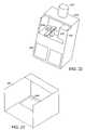
- FIG. 2is a perspective view of the 3-D printer assembly of FIG. 1 .
- FIG. 3is a perspective view of a particular powder feeder.
- FIG. 4is a perspective view of a powder loading subsystem.
- FIG. 5is a schematic of the 3-D printer assembly of FIG. 2 with several parts removed to reveal the overflow chamber.
- FIG. 6is a schematic of another embodiment of the overflow chamber of FIG. 5 .
- FIG. 7is a schematic of a chunk separator.
- FIG. 8is a schematic of a filter system for the vacuum system of FIG. 3 .
- FIG. 9is a schematic of a powder delivery mechanism.
- FIG. 10is a more detailed view of a slat 123 at the drop point 128 .
- FIG. 11is a perspective view of an embodiment of a simple slat.
- FIG. 12is a perspective view of a particular embodiment of a reinforced slat.
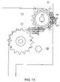
- FIG. 13is a schematic of a conveyor system of FIG. 9 that delivers powdered build material to a separate metering system.
- FIGS. 14A-14Bare schematics of the metering system of FIG. 13 .
- FIG. 15is a schematic of an embodiment in which the feed reservoir 102 is entirely above the plane of the build surface 202 and integrated into a printer unit 200 .
- FIG. 16A-16Bare schematics of a particular cleaning station 300 .
- FIG. 17is a schematic of another particular embodiment of a cleaning station.
- FIG. 18is a schematic of a drop detector for monitoring the condition of a printhead.
- FIG. 19is a schematic of a particular depowdering booth.
- FIG. 20is a schematic cutaway view of the depowdering booth of FIG. 19 .
- FIG. 21is a schematic of a particular diverter of FIG. 20 .
- FIG. 22is a schematic of a depowdering booth incorporated into the printer unit 200 of FIG. 15 .
- FIG. 23is a schematic of a liner for the depowdering booth of FIG. 19 .
- FIG. 24is a schematic of a system for application of a resin infiltrant by spraying.
- FIG. 25is a schematic of a system for spraying a two-component infiltrant.
- FIG. 26is a front cross-sectional view of a sealed-piston.
- FIG. 27is a schematic cross-section of a powder gutter.
- FIG. 28is a schematic cross-section of a magnetic plow configuration.
- FIG. 29is a schematic of a gravity-feed binder supply.
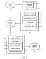
- FIG. 1is a schematic of a particular apparatus for rapid prototyping. As illustrated, there is a digital model 1 , a computer 10 , a three-dimensional (3-D) printer assembly 30 , an as-printed (green) 3-D physical model 3 , a post-processing system 50 , and a completed 3-D physical model 5 .
- a digital model 1there is a digital model 1 , a computer 10 , a three-dimensional (3-D) printer assembly 30 , an as-printed (green) 3-D physical model 3 , a post-processing system 50 , and a completed 3-D physical model 5 .
- the digital model 1is a data representation of an object to be 3-D printed, that is, a digital object to be rendered into a tangible physical entity. Suitable digital models may be created using Computer Aided Design (CAD) software applications or 3-D scanning systems, both of which are available from many different suppliers. The digital models are stored in industry-standard file formats, which can be transmitted electronically and interpreted by application programs running on standard computer equipment.
- CADComputer Aided Design
- the computer 10can be a personal computer, such as a desktop computer or a portable computer.
- the computercan be a stand-alone computer or a part of a network.
- the computer 10runs a custom software application program 15 , which reads digital model files, accepts parameter and preference input from the user, performs a series of detailed calculations and transmits to the 3-D printer assembly 30 the information needed to fabricate the desired physical model.
- the application program 15allows the user to arrange one or more digital models in a virtual volume representing the actual fabrication space within the 3-D printer 30 .
- the application program 15then slices the array of digital models into a plurality of two-dimensional (2-D) layers, each of a predetermined thickness, which are transmitted to an electronic control circuitry 32 housed within the 3-D printer 30 .
- the 3-D printer 30uses an array of ink jet type printheads 35 to deposit binder liquid 37 onto successive layers of a powdered build material 39 , such as disclosed in U.S. Pat. No. 5,902,441 to Bredt, et al., the teachings of which are incorporated herein by reference in their entirety.
- a powdered build material 39such as disclosed in U.S. Pat. No. 5,902,441 to Bredt, et al., the teachings of which are incorporated herein by reference in their entirety.
- the binder liquid 37combines with the powdered build material 39 , the powder reacts and hardens.
- the 3-D printerfabricates a physical layer for each sectioned layer provided by the application program 15 . When the complete set of 2-D cross sections has been processed, a 3-D physical model 3 has been formed.
- the model at this stageis termed “green” to indicate an as-printed condition, prior to post-processing. Further details of binding a powder to form an object are disclosed in U.S. Pat. Nos. 5,340,656 to Sachs et al. and 5,387,380 to Cima et al., the teachings of which are incorporated herein by reference in their entirety.
- the post-processing system 50may be used to produce completed physical models 5 by improving the appearance and the physical properties of green physical models 3 .
- the post-processing system 50may optionally a transport subsystem 52 for handling and transporting printed models, a drying subsystem 54 for completely drying physical models, a depowdering subsystem 56 for thoroughly removing the residual powdered build material from printed models, and an infiltration subsystem 58 for coating and infiltrating printed models with various substances.
- FIG. 2is a perspective view of the 3-D printer assembly of FIG. 1 .
- Its constituent subassembliesinclude a powder feeder 100 and a printer unit 200 .
- the powder feeder 100 and the printer 200can be easily uncoupled from each other for shipping, service and cleaning. Further, the user has the option of maintaining several interchangeable powder feeders 100 for use with a single printer unit 200 , each feeder containing a different powdered build material to facilitate easy changeover from one material to another.
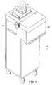
- FIG. 3is a perspective view of a particular powder feeder.
- the powder feeder 100includes a vacuum subsystem 110 with an associated vacuum inlet 112 , a feed reservoir 102 storing a supply of the powdered build material 39 ( FIG. 1 ), and a metering system 170 , which delivers powdered build material to the printer unit 200 in measured quantities.
- the following paragraphsdescribe in detail the design and operation of the powder feeder 100 and its subassemblies.
- Loading powdercan be a messy process that can cause some of the powder to become airborne and allow the powder to deposit on the printer, the user, and the surrounding environment. Similar problems exist with recycling powder that has not been printed upon. There are two types of recyclable powder: 1) powder that was deposited in the build chamber but that was not used to form a part; and 2) excess powder used for the spreading process in order to ensure a complete layer is deposited; this excess powder ultimately drops into the overflow chamber. Both types of powder have the same difficulties in being recycled.
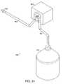
- FIG. 4is a perspective view of a powder loading subsystem.
- the subsystemloads the feed reservoir 102 with the powdered build material 39 .
- a vacuum system 110is attached to the feed reservoir 102 (other embodiments could include a detached vacuum).
- the vacuum system 110forms the top of the powder feeder 100 .
- the feed reservoir 102is filled by drawing powdered build material from a shipping container 9 into the feed reservoir through a vacuum hose 111 coupled to the vacuum inlet 112 . This allows the user to fill the reservoir without contacting the powder.
- Aircan also be injected into the container 9 (which could be the container in which the powder is shipped from its place of manufacture) through a compressed air hose 101 .
- the compressed airaids in vacuuming the powder out of the container by making the powder flow more easily. This technique can be automated so that the feed reservoir 102 maintains a store of a sufficient quantity of build material.
- a vacuum system having an outlet that empties into the feed reservoir of the 3-D printersolves a variety of problems.
- user satisfactionis increased and the machine is made more reliable because less airborne powder, which can contaminate machine components (e.g., bearing and electronics), is generated.
- machine componentse.g., bearing and electronics
- the vacuum system 110can be used to remove most of the powder from the printed model 3 ( FIG. 1 ).
- the usercan use the vacuum system 110 to transport into the feed reservoir 102 the remainder of the powder in the build chamber and any powder than has been deposited (by accident or design) elsewhere on the printer.
- the 3-D printer 200spreads successive layers of powdered build material in the manner disclosed in U.S. Pat. No. 5,902,441 to Bredt, et al., depositing a quantity averaging approximately 20% of total amount spread into an overflow chamber.
- Another specific use for the vacuum system 110is to return the powdered build material deposited in the overflow chamber to the feed reservoir 102 .
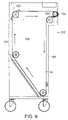
- FIG. 5is a schematic of the 3-D printer assembly of FIG. 2 with several parts removed to reveal the overflow chamber 230 .
- the overflow chamber 230is connected through plumbing 113 and a valve 114 to the vacuum inlet 112 .
- the vacuum system 110When the vacuum system 110 is activated, powdered build material from the overflow chamber 230 is drawn into the plumbing 113 and thence into the feed reservoir 102 .
- An opening 115is provided at the valve 114 to permit a vacuum hose to be attached for performing the filling and cleaning functions described above.
- the valve 114is set to block the connection through the plumbing 113 to the overflow chamber 230 and open the connection to the opening 115 .
- FIG. 6is a schematic of another embodiment of the overflow chamber of FIG. 5 .
- the overflow chamber 230has an overflow chamber outlet 235 permanently attached at its lower end.
- the userattaches a vacuum hose at one end to the overflow chamber outlet 235 and at the other end to the vacuum inlet 112 of the vacuum system 110 ( FIG. 3 ).
- the vacuum system 110is then activated, and powdered build material is transported from the overflow chamber 230 to the feed reservoir 102 .
- the inlet 112 of the vacuum system 110is connected directly to the feed reservoir 102 , foreign matter may enter the feed reservoir. If the foreign matter is similar in particle size to the powdered build material (e.g., dust) the foreign matter may have no detectable effect on the 3-D printer or the 3-D printing process. If large particles or chunks enter the feed reservoir, however, these chunks may damage the mechanism or, if they pass through the feed reservoir and are deposited in the build chamber, they may damage the physical model being printed.
- the powdered build materiale.g., dust
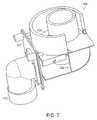
- FIG. 7is a schematic of a chunk separator.
- the chunk separator 120is placed between the vacuum system inlet 112 and the feed reservoir 102 .
- the separator 120causes air, powdered build material and any entrained foreign matter that enters the inlet 112 to follow a generally circular airflow path 122 around the inside of the device.
- the powdered build material and airpass upward through the separator screen 125 , leaving the separator 120 , and entering the feed reservoir 102 .
- Any entrained foreign matter in the airflow 122 that is too large to pass through the screen 125continues to circulate around the interior of the device. This recirculation action tends to fracture and abrade any chunks of foreign matter, allowing some part of them eventually to pass through the screen 125 .
- a faceplate 127 of the separator 120is removable to provide an access port for removal of accumulated debris.
- FIG. 8is a schematic of a filter system for the vacuum system of FIG. 3 .
- the vacuum system 110includes two filters 118 -A, 118 -B located inside the feed reservoir 102 to prevent fine particles (such as the powdered build material) that are picked up by the vacuum system 110 from being exhausted to the room.
- the filterswill become coated with powdered build material, and that this coating will reduce the airflow through the filter, reducing the pressure differential generated at the vacuum inlet 112 .
- the filter systemis used to clean the filters.
- a system of valves 119 -A, 119 Bcloses the vacuum source to a single filter outlet and diverts air at or near atmospheric pressure into the same outlet, reversing the flow direction and blowing off accumulated powder, which then falls into the feed reservoir 102 .
- the other filter in the systemmaintains airflow and vacuum inside the feed reservoir 102 to induce this airflow.
- This purging cycleis periodically sequenced through each filter element. In this manner the filters can be cleaned without intervention by the user and without requiring the user to stop using the vacuum system while the filters are automatically cleaned.
- powder feeder 100The principal function of powder feeder 100 is to deliver powdered build material to the 3-D printer unit 200 in measured quantities as required by the printing process.
- FIG. 9is a schematic of a powder delivery mechanism.
- the feed reservoir 102has, in particular, volumetric capacity of approximately 8.6 ft 3 , or enough powdered build material to print 1.75 of the largest physical models possible within the constraints of the printer unit 200 .
- the powder delivery mechanism 120includes a conveyor 122 having slats 123 attached to two strands of conveyor chain. The conveyor is driven by an electric motor and moves in recirculating fashion in the direction indicated by the arrows.
- the slats 123pass through the powdered build material 39 in the feed reservoir 102 , and each slat 123 carries some of the powdered build material 39 to a point above the plane of the build surface 202 .
- FIG. 10is a more detailed view of a slat 123 at the drop point 128 .
- the system shown in FIG. 9has the added advantage that the slats are constantly moving along the periphery of the feed reservoir 102 . In so doing, the motion of the slats 123 stirs the volume of powder and prevents bridges and areas of stagnant powder from being formed. It is desirable to avoid stagnant areas because the powder in these areas cannot be extracted from the feed reservoir by the conveyor system 122 . Such stagnant areas represent powder that is wasted because it cannot be used during the normal operation of the feed conveyor.
- the force on the slats 123 being dragged through the reservoir by the conveyor 122may be very large.
- the slat geometrycan be altered to stiffen them sufficiently to allow them to travel through the powdered build material without permanently deforming.
- FIG. 11is a perspective view of an embodiment of a simple slat.
- the slat 123includes a leg 124 and is connected to the two conveyor chains 122 -A, 122 -B.
- This slatdelivers an optimum volume of powdered build material but may be too weak to withstand the loads placed upon it.
- the legcan be strengthened for greater stiffness.
- FIG. 12is a perspective view of a particular embodiment of a reinforced slat.
- the same slat 123includes an additional stiffening member 126 that adds to the strength of the member without increasing the amount of powdered build material it delivers.
- the powderis carried on the surface 123 -S of the slat 123 .
- This configurationhas an additional advantage that the moment created by the resistance of the powder wraps the chain 122 -A, 122 -B onto its pulleys or sprockets. A moment in the opposite direction tends to cause the chain to jam rather than going around the pulley or sprocket.
- FIG. 13schematic of a conveyor system of FIG. 9 that delivers powdered build material to a separate metering system.
- the metering system 130regulates the flow of powdered build material into the 3-D printer.
- FIGS. 14A-14Bare schematics of the metering system of FIG. 13 .
- a cylindrical metering roller 133is enclosed by a closely fitting tube 134 .
- the metering roller 133has four axial grooves in its surface, which constitute metering cavities 135 -A, 135 -B, 135 -C, and 135 -D.
- the tube 134has an entrance slot 136 and an exit slot 137 .
- powdered build materialenters a metering cavities 135 -A through the entrance slot 136 .
- powdered build materialis captured between the metering roller 133 and the tube 134 and is carried around to the exit slot 137 , where it is discharged onto the build surface 202 ( FIG. 13 ).
- the clearance between the metering roller 133 and the tube 134is approximately 0.015 in., which has been determined to be large enough to allow the metering roller 133 to rotate freely but small enough to prevent unwanted radial powder flow between the inlet slot 136 and the outlet slot 137 .
- the metering cavities 135each hold approximately 3 in 3 of powdered build material, which is equal to the material required for the smallest desirable increment of layer thickness. This allows an amount of powdered build material consistent with any desired layer thickness be delivered by causing the metering roller 133 to rotate until the appropriate number of metering cavities 135 have picked up and delivered powdered build material.
- a paddle wheel agitator 138which disturbs the powdered build material above the metering roller 133 to break bridges and keep the powdered build material flowing into the metering cavities 135 .
- a flicker blade 139rotates in the opposite direction from the metering roller 133 .
- the flicker blade 139wipes the powdered build material out of the metering cavity 135 . This technique prevents variation in the amount of powdered build material delivered, even when the materials are sticky or have a tendency to bridge.
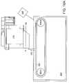
- FIG. 15is a schematic of an embodiment in which the feed reservoir 102 is entirely above the plane of the build surface 202 and integrated into a printer unit 200 ′.
- Powderis metered out of the feed reservoir 102 onto the plane of the build surface 202 and spread over a build box 220 by the gantry 210 .
- the powderis then printed on by a printhead or printhead array 205 .
- the metering systemcould be located at the bottom of the feed reservoir and fed by gravity.
- the metering systemcould be located at the bottom of the feed reservoir and the reservoir would include paddlewheel or vibratory mechanisms to ensure the flow of the powder into the metering system if the powder is a type prone to clumping or bridging.
- the feed reservoircan be mounted to the gantry 210 , which is capable of moving across the build chamber. Powder could be continuously metered out of the feed reservoir and deposited directly onto the build chamber 220 as the gantry is moved across.
- a roller or doctor bladecould be used to smooth and level the surface after the feed reservoir passed over.
- the 3-D printer unit 200uses an array of inkjet printheads to selectively dispense a binder material onto successive layers of powdered build material, selectively hardening the build material and forming 3-D physical models.
- This technologyis disclosed in detail in the incorporated patents, e.g., U.S. Pat. No. 5,902,441 to Bredt, et al.
- An aspect of a successful inkjet printing deviceis a technique for keeping the face of the printhead clean. Keeping the printheads clean in a 3-D printing environment is particularly demanding because of the high concentration of airborne powdered build material in the vicinity of the printhead face. In most inkjet printers, the printhead face is routinely wiped with a squeegee-like wiper element.
- FIG. 16A-16Bare schematics of a particular cleaning station 300 .
- a wiper element 305is situated to wipe the face of a printhead 205 as the printhead translates over the wiper 305 in the left direction indicated by the arrow.
- contaminating materialis transferred from the face of the printhead 205 to the wiper element 305 . This methods works well as long as contaminating material is not allowed to accumulate on the wiper element.
- the wiper element 305is mounted on a belt 302 .
- the belt 302runs on pulleys 304 -A, 304 -B, which are rotatable by a motor 306 .
- the wiper element 305is stationary in position to wipe the face of the printhead 205 .
- the motor 306has been activated, causing the wiper element 305 to be dragged over the cleaning surface 308 of a wiper block 309 in the direction indicated by the arrow, transferring any accumulated contamination to the wiper block 309 .
- the wiper block 309is routinely replaced to maintain a clean wiping surface.
- FIG. 17is a schematic of another particular embodiment of a cleaning station.
- a wiper element 305 ′can be retracted for cleaning into the depressed cleaning station 300 ′, which is filled to a level 308 ′ with a cleaning fluid 309 ′.
- An agitator 307can agitate the fluid 309 ′ by various means, such as ultrasonic vibration, rapid circulation of the cleaning fluid, or injection of air bubbles.
- the service life of a printheadvaries depending on use and other variables that may not be controlled. Sometimes printheads fail partially, with some jets not firing while others continue to fire normally. At other times an entire printhead fails, with all of its jets malfunctioning. Because there is a large variation in how printheads fail and in the overall life of a printhead and because the failure of a printhead can cause the failure of the 3-D printer to produce the desired physical model it is useful to be able to detect the condition of a printhead and to be able to determine whether some, most or all of its jets are firing.
- FIG. 18is a schematic of a drop detector for monitoring the condition of a printhead. After the printhead 205 is moved into position above the drop detector 400 , each jet of the printhead 205 is fired independently a number of times sufficient for the detector to positively detect whether the jet is firing normally. In an alternative embodiment, a group of jets is fired simultaneously, and the detector determines how many jets within each group are firing normally without determining which specific jets are malfunctioning. This method is quicker because several jets can be tested at once.
- a particular drop detector 400can work by optical means.
- an emittercan emit a frequency of light to which the binder is opaque (infrared, for instance). That light beam is interrupted when a drop fired by the printhead passes through the beam. Failure to detect the interruption indicates a malfunctioning jet. If the detection beam were sufficiently narrow, miss-aimed jets can also be detected.
- Another particular drop detector 400works by detecting drop impacts on a membrane attached to a microphone or a piezo-electric detector.
- the print jobis interrupted as soon as a malfunction is detected.
- the usermay have a brief period to replace the faulty printhead or else the job is aborted.
- the print jobcan be aborted in any case. This would save time and reduce the amount of powder consumed.
- a drop detectorif the printhead fails partially, or if one printhead in a printer with several printheads fails totally or partially, a large quantity of powder could be printed on even though the resulting part would not be useful.
- aborting the print job when a defect is detectedthe user saves the expense of the binder and powder that would have been wasted if the defect were not detected.
- a color 3-D printerhaving 4 or more printheads where at least one printhead is supplied with binder with a colorant of one of the primaries (cyan, magenta, and yellow) another mode of operation is possible.
- the detectordetermines that one of the printheads has failed the job is completed in a monochrome mode (or, to improve speed, a mode which uses all colors except the color of the faulty printhead) using the overlapping print mode mentioned above. In this way the user can get a useful part but not a color part or, in the alternative case, a part that has color but is not colorized per the design.
- FIG. 19is a schematic of a particular depowdering booth.
- a flow of airis created in the depowdering booth 500 to contain and direct the cloud of powdered build material created by a jet of compressed air directed at a physical model.
- An aperture 503provides access to the interior of the depowdering booth 500 .
- the physical model to be depowderedrests on a surface 504 inside of the aperture 503 .
- a window 505can be closed to help contain airborne powdered build material, and can be opened to allow a large physical model to be placed within the depowdering booth 500 .
- a shroud 506covers a blower 510 to attenuate the noise generated by operation of the equipment.
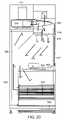
- FIG. 20is a schematic cutaway view of the depowdering booth of FIG. 18 .
- Airis circulated through the depowdering booth 500 by the blower 510 , which is powered by an electric motor 515 .
- airexits from the blower 510 into a diverter 530 , where the flow is divided into two separate streams, a primary air curtain flow 517 carried by an air curtain duct 518 , and a secondary powder clearing flow 519 . Both flows recombine in the vicinity of the physical model 3 supported on a turntable 520 , entraining powdered build material.
- the flowthen passes through openings in a supporting surface 522 and through filters 524 . Filtered air exits from the filters 524 into a clean air plenum 526 and thence enters the inlet of the blower 510 to complete its circuit.
- powdered build materialcollects on the surfaces of the filters 524 , eventually restricting the airflow and reducing the efficiency of the system.
- a pulse of airis periodically introduced into the interior of the filters 524 from the clean air plenum 526 . This causes the flow of air through the filters 524 to reverse momentarily, forcing the accumulated powdered build material to separate from the surfaces of the filters 524 and to fall into a drawer 528 .
- the powder collection drawer 528can be removed to be emptied.
- One objectiveis to prevent airborne powdered build material from escaping from the aperture 503 of the depowdering booth 500 ( FIG. 19 ), thereby contaminating the surrounding environment.
- a high-speed jet of compressed airis directed at the physical model 3
- a substantial portion of the compressed air reflected from the physical modelmay be directed out of the depowdering booth 500 toward the user.
- the primary air curtain flow 517( FIG. 20 ) is directed vertically down the face of the window 505 ( FIG. 19 ), effectively capturing and deflecting the outwardly directed stream.
- the optimum balance between the primary air curtain flow 517 and the secondary air clearing flow 519varies somewhat with the characteristics of the powdered build material being removed and with the geometry of the physical model being depowdered. For this reason, the diverter 530 is adjustable.
- FIG. 21is a schematic of a particular diverter of FIG. 20 .
- a mechanical linkage 533causes a diverter vane 534 to rotate up and down as indicated by arrows around a pivot point 535 .
- the edge 536 of the diverter vane 534moves downward, the primary air curtain flow 517 down the air curtain duct 518 assumes more of the total airflow.
- the edge 536 of the diverter vane 534moves upward, the secondary air cleaning flow 519 into the exhaust plenum 538 assumes more of the total airflow.
- FIG. 22is a schematic of a depowdering booth incorporated into the printer unit 200 ′ of FIG. 15 .
- a blower 510is coupled to the depowdering booth 500 . Air flows downward across the front opening of the booth 500 , entrains powder, passes through filters (not shown) and is returned to the inlet of the blower 510 . In this configuration, depowdering can be performed on the same equipment as printing
- a cartcan be used to transfer large or heavy physical models to the depowdering booth 500 .
- Physical modelsare printed on a pallet, which is placed on the 3-D printer build table before printing begins.
- the cartis positioned adjacent to the printer unit 200 ′ and the gap between them is bridged by a set of transfer rails. These rails carry a multiplicity of rollers, which allow the pallet, carrying the printed physical model to slide smoothly onto the cart.
- the cartis then positioned adjacent to the depowdering booth 500 , and transfer rails are used to slide the pallet, carrying the printed physical model into the depowdering booth 500 .
- the physical models created by the 3-D printing processare porous, making it possible to change their properties by infiltrating them with various resins. Resin can be applied to the physical model in many ways including immersion, brushing and pouring. Each of these methods is time consuming, wasteful of resin or both.
- the present inventionapplies resin to the physical model by a spraying process. Many of the infiltrants used on 3-D printed models are adhesives. Spraying adhesives creates a number of problems. First, it is necessary to contain any vapors created during the process (as for instance from overspray, or bounce back of atomized spray). If the vapors are not contained they may deposit on the user, the user's clothing, or other objects.
- the vaporsmay pose a health or environmental hazard.
- Another problem with spraying adhesivesis that the spray equipment gets coated with the adhesive and must be cleaned thoroughly after each use. This is tedious and may create health or environmental problems if the solvent for the adhesive is hazardous.
- FIG. 23is a schematic of a liner for the depowdering booth of FIG. 19 .
- a liner 560protects the booth 500 from infiltrant overspray.
- the liner 560includes a pre-filter 562 to capture airborne adhesive droplets to prevent them from coating the filters 524 ( FIG. 20 ) in the depowdering booth 500 .
- the userunfolds the liner 560 , which is preferably made of corrugated cardboard, inside the depowdering booth 560 , and sprays infiltrant on the physical model.
- the linercan be used to protect a vent hood or ductless fume hood.
- FIG. 24is a schematic of a system for application of a resin infiltrant by spraying.
- resinis pumped through disposable tubing 604 from a infiltrant reservoir 602 by a peristaltic pump 603 , and is then forced through a disposable spray nozzle 605 .
- a system of disposable components and a peristaltic pumpwhich is not wetted by the adhesive, an inexpensive and user-friendly system for spraying adhesives is created.
- the clean upconsists of disposing of the tubing and spray nozzle.
- FIG. 25is a schematic of a system for spraying a two-component infiltrant.
- a two-component infiltrantis an infiltrant that cures when the two components are combined.
- resin componentsare pumped through the disposable tubing 614 from infiltrant reservoirs 616 , 617 by a 2-head peristaltic pump 618 .
- the two resin componentsare combined in a static mixer 619 and the mixture is then forced through a disposable spray nozzle 615 .
- the mixing ratio for the two-component systemcan be maintained by using an appropriate diameter for each tube. In particular, a one to one ratio for the components requires that both tubes be the same diameter.
- FIG. 26is a front cross-sectional view of a sealed piston. As shown, an energized tube 712 pushes outward onto the felt 714 on the inner surface of a piston box 710 . The tube 712 is enveloped by the piston assembly plate 715 of the piston assembly 718 on its top and side. Felt 714 is placed in between the tube seal 712 and the side of the piston box 710 to form a seal.
- 3-D printinginvolves a supply box, from which powder is fed, and a build box where part fabrication takes place.
- powdercollects around these powder boxes on a surface (called the deck) until the powder can be vacuumed away.
- Powder that migrates during the printing processcan be a nuisance and can cause performance problems with parts of the 3-D printer, in particular the printhead and the service station.
- the printhead and the service stationmust be located close to the plane of the top edges of the powder boxes. If the deck is coplanar with these top edges, any powder that accumulates on the deck is potentially close to these sensitive components. Therefore, a more desirable embodiment has the surface of the deck depressed below the edges of the powder boxes, forming a gutter for the powder to fall into.
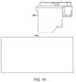
- FIG. 27is a schematic cross-section of a powder box.
- the printer deck 802is depressed below the top edges 804 T of the powder boxes. This configuration forms a gutter 805 where the migrated powder can collect.
- Plowscan prevent migrating powder from flowing off the sides of the piston boxes.
- One methodis to use plows that are fastened to the gantry with springs, causing the plows to exert a force downward onto the top deck of the 3-D printer.
- a particular printerincludes a plow with a small magnet inside to exert a force. This is easier to assemble and disassemble than the plow with a spring.
- a further improvementinvolves the location of the plows.
- FIG. 28is a schematic cross-section of a magnetic plow configuration.
- Plows 810 - 1 and 810 - 2are affixed to the printer gantry 210 ′ in such a way that they are free to move perpendicular to the walls 804 - 1 and 804 - 2 of the powder boxes but are effectively fixed with respect to the gantry 210 ′ in all other dimensions.
- Walls 804 - 1 and 804 - 2are constructed of a soft magnetic material such as steel.
- Each plowhas an embedded magnet 810 - 1 and 810 - 2 that acts upon its respective wall with enough force to keep the plow in tight contact with the wall, forming a barrier to prevent powder 39 from spilling onto deck 802 during a powder spreading operation.
- 3-D printingtypically utilizes commercially available printheads that were designed for 2-D printing.
- a special binder material that matches the powder being printedis substituted for the ink normally dispensed by the printhead. Since a typical 3-D printed part requires much more binder than can be contained inside a printhead, and since printheads cannot practically be replaced while a part is being built, it is necessary to continuously replenish the binder in the printhead while the printer is operating. This is typically accomplished by making a tubing connection between the moving printhead and a stationary supply of binder.
- the pressure inside the head at the entrance to the inkjet channelsmust be maintained at a small negative pressure, typically at a pressure between ⁇ 3 and ⁇ 6 inches of water.
- One prior art techniqueemploys an ink supply whose free surface is maintained at a level approximately 4 inches below the printhead outlet.
- Printheadsare available with built-in pressure regulators that maintain the required negative internal pressure while the printhead feed line pressure varies over a broad range of positive pressures. In general, enough pressure must be exerted on the binder at the supply end of the binder feed tubing to cause binder to flow through the tube at an adequate rate to keep the printhead full. The pressure required depends primarily on the restrictive characteristics of the feed tubing and the relative height of the supply with respect to the printhead.
- One prior art techniqueemploys a pump that maintains the supply pressure at the inlet to the printhead. Because of its complexity, this solution is expensive and potentially unreliable.
- FIG. 29is a schematic of a gravity feed binder supply.
- a stationary supply of binder 1002is plumbed to printhead 205 through a length of tubing 1004 .
- the binder supply 1002is located at a sufficient height above the printhead 205 to keep the printhead supplied through tubing 1004 .
- the free surface of the bindermay vary between 3.5 and 5 inches above the bottom surface of the printhead. This height provides enough pressure to supply the printhead with binder at a rate in excess of the required 8 grams/minute through a segment of tubing having an inside diameter of 1/16 inch and a length of approximately 6 feet.
- Persons skilled in the artwill recognize that other combinations of supply height and tubing dimensions could be selected to yield the required flow rate.
Landscapes
- Engineering & Computer Science (AREA)
- Chemical & Material Sciences (AREA)
- Materials Engineering (AREA)
- Manufacturing & Machinery (AREA)
- Mechanical Engineering (AREA)
- Physics & Mathematics (AREA)
- Optics & Photonics (AREA)
- Heating, Cooling, Or Curing Plastics Or The Like In General (AREA)
- Testing, Inspecting, Measuring Of Stereoscopic Televisions And Televisions (AREA)
- Superconductors And Manufacturing Methods Therefor (AREA)
- Ink Jet (AREA)
Abstract
Description
Claims (13)
Priority Applications (2)
| Application Number | Priority Date | Filing Date | Title |
|---|---|---|---|
| US12/192,412US7686995B2 (en) | 1996-12-20 | 2008-08-15 | Three-dimensional printer |
| US12/710,594US8017055B2 (en) | 1996-12-20 | 2010-02-23 | Three-dimensional printer |
Applications Claiming Priority (6)
| Application Number | Priority Date | Filing Date | Title |
|---|---|---|---|
| US08/771,009US6007318A (en) | 1996-12-20 | 1996-12-20 | Method and apparatus for prototyping a three-dimensional object |
| US09/416,787US6375874B1 (en) | 1996-12-20 | 1999-10-13 | Method and apparatus for prototyping a three-dimensional object |
| US09/851,502US6989115B2 (en) | 1996-12-20 | 2001-05-08 | Method and apparatus for prototyping a three-dimensional object |
| US10/260,224US7037382B2 (en) | 1996-12-20 | 2002-09-27 | Three-dimensional printer |
| US11/335,282US7435368B2 (en) | 1996-12-20 | 2006-01-19 | Three-dimensional printer |
| US12/192,412US7686995B2 (en) | 1996-12-20 | 2008-08-15 | Three-dimensional printer |
Related Parent Applications (1)
| Application Number | Title | Priority Date | Filing Date |
|---|---|---|---|
| US11/335,282ContinuationUS7435368B2 (en) | 1996-12-20 | 2006-01-19 | Three-dimensional printer |
Related Child Applications (1)
| Application Number | Title | Priority Date | Filing Date |
|---|---|---|---|
| US12/710,594DivisionUS8017055B2 (en) | 1996-12-20 | 2010-02-23 | Three-dimensional printer |
Publications (2)
| Publication Number | Publication Date |
|---|---|
| US20090011066A1 US20090011066A1 (en) | 2009-01-08 |
| US7686995B2true US7686995B2 (en) | 2010-03-30 |
Family
ID=25090409
Family Applications (4)
| Application Number | Title | Priority Date | Filing Date |
|---|---|---|---|
| US08/771,009Expired - LifetimeUS6007318A (en) | 1996-12-20 | 1996-12-20 | Method and apparatus for prototyping a three-dimensional object |
| US09/416,787Expired - LifetimeUS6375874B1 (en) | 1996-12-20 | 1999-10-13 | Method and apparatus for prototyping a three-dimensional object |
| US12/192,412Expired - Fee RelatedUS7686995B2 (en) | 1996-12-20 | 2008-08-15 | Three-dimensional printer |
| US12/710,594Expired - Fee RelatedUS8017055B2 (en) | 1996-12-20 | 2010-02-23 | Three-dimensional printer |
Family Applications Before (2)
| Application Number | Title | Priority Date | Filing Date |
|---|---|---|---|
| US08/771,009Expired - LifetimeUS6007318A (en) | 1996-12-20 | 1996-12-20 | Method and apparatus for prototyping a three-dimensional object |
| US09/416,787Expired - LifetimeUS6375874B1 (en) | 1996-12-20 | 1999-10-13 | Method and apparatus for prototyping a three-dimensional object |
Family Applications After (1)
| Application Number | Title | Priority Date | Filing Date |
|---|---|---|---|
| US12/710,594Expired - Fee RelatedUS8017055B2 (en) | 1996-12-20 | 2010-02-23 | Three-dimensional printer |
Country Status (8)
| Country | Link |
|---|---|
| US (4) | US6007318A (en) |
| EP (4) | EP0949993B2 (en) |
| JP (2) | JP2001507295A (en) |
| AT (3) | ATE431774T1 (en) |
| CA (1) | CA2275565A1 (en) |
| DE (3) | DE69734408T2 (en) |
| ES (2) | ES2248457T3 (en) |
| WO (1) | WO1998028124A2 (en) |
Cited By (45)
| Publication number | Priority date | Publication date | Assignee | Title |
|---|---|---|---|---|
| US20100151136A1 (en)* | 1996-12-20 | 2010-06-17 | Z Corporation | Three-Dimensional Printer |
| US20130108726A1 (en)* | 2011-03-02 | 2013-05-02 | Bego Medical Gmbh | Device for the generative manufacturing of three-dimensional components |
| USD711463S1 (en)* | 2013-02-18 | 2014-08-19 | Dws S.R.L. | Stereolithography machine |
| USD722108S1 (en)* | 2013-03-13 | 2015-02-03 | Formlabs, Inc. | Three-dimensional printer |
| USD729309S1 (en)* | 2013-04-12 | 2015-05-12 | Pirate3Dp Pte. Ltd. | Three-dimensional printer |
| USD732586S1 (en)* | 2014-11-13 | 2015-06-23 | Xyzprinting, Inc. | 3D printer |
| USD732587S1 (en)* | 2014-11-13 | 2015-06-23 | Xyzprinting, Inc. | 3D printer |
| USD732588S1 (en)* | 2015-01-05 | 2015-06-23 | Xyzprinting, Inc. | 3D printer |
| USD736838S1 (en)* | 2013-12-20 | 2015-08-18 | Maurizio Ettore Costabeber | Stereolithography machine |
| USD737870S1 (en)* | 2014-01-21 | 2015-09-01 | Robert Kevin Houston | Three dimensional motion platform |
| USD738410S1 (en)* | 2014-09-24 | 2015-09-08 | Xyzprinting, Inc. | Chassis of 3D printer |
| USD739885S1 (en)* | 2014-05-30 | 2015-09-29 | Xyzprinting, Inc. | 3D printer |
| US20150298397A1 (en)* | 2014-04-22 | 2015-10-22 | Microjet Technology Co., Ltd. | Powder recycling system |
| USD751613S1 (en)* | 2014-10-21 | 2016-03-15 | Seiko Epson Corporation | Combined container and ink tanks for a printer |
| USD754763S1 (en)* | 2013-03-15 | 2016-04-26 | Arburg Gmbh + Co. Kg | Device for producing three-dimensional articles |
| USD757132S1 (en)* | 2015-01-04 | 2016-05-24 | Xyzprinting, Inc. | 3D printer |
| USD763332S1 (en)* | 2015-05-31 | 2016-08-09 | Huai Wu | 3D printhead |
| USD770545S1 (en)* | 2014-06-02 | 2016-11-01 | Natural Machines, Inc. | Three-dimensional printer |
| USD771184S1 (en) | 2014-10-21 | 2016-11-08 | Seiko Epson Corporation | Combined container and ink tanks for a printer |
| US9527272B2 (en) | 2014-03-07 | 2016-12-27 | Polar 3D Llc | Method for printing a three-dimensional object |
| US20170232679A1 (en)* | 2014-08-05 | 2017-08-17 | Laing O'rourke Australia Pty Limited | Apparatus for Fabricating an Object |
| US9802355B2 (en) | 2013-10-21 | 2017-10-31 | Made In Space, Inc. | Nanoparticle filtering environmental control units |
| US9821543B1 (en)* | 2016-10-07 | 2017-11-21 | General Electric Company | Additive manufacturing powder handling system |
| US20170348771A1 (en)* | 2016-06-01 | 2017-12-07 | Sodick Co., Ltd. | Three-dimensional printer |
| WO2018199879A1 (en)* | 2017-04-24 | 2018-11-01 | Hewlett-Packard Development Company, L.P. | Detecting flying liquid drops |
| US10538030B2 (en)* | 2013-11-26 | 2020-01-21 | Carbon, Inc. | Rapid 3D continuous printing of casting molds for metals and other materials |
| US10814608B2 (en) | 2014-09-29 | 2020-10-27 | Hewlett-Packard Development Company, L.P. | Generating three-dimensional objects and generating images on substrates |
| US11226058B2 (en) | 2016-05-12 | 2022-01-18 | Hewlett-Packard Development Company, L.P. | Outlet structure |
| US11285668B2 (en) | 2016-05-12 | 2022-03-29 | Hewlett-Packard Development Company, L.P. | 3D build platform refill opening and cap |
| US20220105678A1 (en)* | 2016-02-26 | 2022-04-07 | Trio Labs, Inc. | Method and apparatus for solid freeform fabrication of objects utilizing in situ infusion |
| US11472111B2 (en) | 2018-05-15 | 2022-10-18 | Hewlett-Packard Development Company, L.P. | Resource consumption control |
| US11878466B2 (en) | 2019-01-29 | 2024-01-23 | Hewlett-Packard Development Company, L.P. | Sealing assemblies |
| US11911964B2 (en) | 2015-10-30 | 2024-02-27 | Seurat Technologies, Inc. | Recycling powdered material for additive manufacturing |
| US12042988B2 (en) | 2019-05-23 | 2024-07-23 | General Electric Company | Additive manufacturing apparatuses and methods |
| US12059841B2 (en) | 2019-05-23 | 2024-08-13 | General Electric Company | Additive manufacturing recoat assemblies including sensors and methods for using the same |
| US12076918B2 (en) | 2019-05-23 | 2024-09-03 | General Electric Company | Additive manufacturing apparatuses and methods for using the same |
| US12097709B2 (en) | 2019-05-23 | 2024-09-24 | General Electric Company | Cleaning fluids for use in additive manufacturing apparatuses and methods for monitoring status and performance of the same |
| US12162074B2 (en) | 2020-11-25 | 2024-12-10 | Lawrence Livermore National Security, Llc | System and method for large-area pulsed laser melting of metallic powder in a laser powder bed fusion application |
| US12172370B2 (en) | 2019-05-23 | 2024-12-24 | General Electric Company | Recoat assemblies for additive manufacturing systems and methods for using the same |
| US12194681B2 (en) | 2020-10-21 | 2025-01-14 | General Electric Company | Material supply system and method for using the same |
| US12208583B2 (en) | 2019-05-23 | 2025-01-28 | General Electric Company | Wiper arrays for use in additive manufacturing apparatuses |
| US12233643B2 (en) | 2019-05-23 | 2025-02-25 | General Electric Company | Printing assemblies and methods for using the same |
| US12257778B2 (en) | 2019-05-23 | 2025-03-25 | General Electric Company | Additive manufacturing recoat assemblies including a vacuum and methods for using the same |
| US12280596B2 (en) | 2019-05-23 | 2025-04-22 | General Electric Company | Cleaning systems for additive manufacturing apparatuses and methods for using the same |
| US12358227B2 (en) | 2019-05-23 | 2025-07-15 | General Electric Company | Fluid management and circulation systems for use in additive manufacturing apparatuses |
Families Citing this family (397)
| Publication number | Priority date | Publication date | Assignee | Title |
|---|---|---|---|---|
| US5902441A (en) | 1996-09-04 | 1999-05-11 | Z Corporation | Method of three dimensional printing |
| US7332537B2 (en) | 1996-09-04 | 2008-02-19 | Z Corporation | Three dimensional printing material system and method |
| US6357855B1 (en)* | 1996-09-27 | 2002-03-19 | 3D Systems, Inc. | Non-linear printhead assembly |
| US6989115B2 (en)* | 1996-12-20 | 2006-01-24 | Z Corporation | Method and apparatus for prototyping a three-dimensional object |
| US7037382B2 (en)* | 1996-12-20 | 2006-05-02 | Z Corporation | Three-dimensional printer |
| US20050023710A1 (en)* | 1998-07-10 | 2005-02-03 | Dmitri Brodkin | Solid free-form fabrication methods for the production of dental restorations |
| US6506477B1 (en) | 1998-12-17 | 2003-01-14 | Minolta Co., Ltd. | Apparatus and method for forming three-dimensional object |
| US6612824B2 (en) | 1999-03-29 | 2003-09-02 | Minolta Co., Ltd. | Three-dimensional object molding apparatus |
| JP2001047518A (en)* | 1999-06-02 | 2001-02-20 | Leben Co Ltd | Three-dimensional object manufacturing method and three-dimensional object manufacturing apparatus |
| DE19937260B4 (en)* | 1999-08-06 | 2006-07-27 | Eos Gmbh Electro Optical Systems | Method and device for producing a three-dimensional object |
| JP2001150556A (en)* | 1999-09-14 | 2001-06-05 | Minolta Co Ltd | Three-dimensional printing apparatus and three-dimensional printing method |
| US6519500B1 (en) | 1999-09-16 | 2003-02-11 | Solidica, Inc. | Ultrasonic object consolidation |
| US6814823B1 (en) | 1999-09-16 | 2004-11-09 | Solidica, Inc. | Object consolidation through sequential material deposition |
| HK1048617B (en) | 1999-11-05 | 2004-12-03 | 3D系统公司 | Methods of three-dimensional printing |
| EP1415792B1 (en) | 1999-11-05 | 2014-04-30 | 3D Systems Incorporated | Methods and compositions for three-dimensional printing |
| GB9927127D0 (en)* | 1999-11-16 | 2000-01-12 | Univ Warwick | A method of manufacturing an item and apparatus for manufacturing an item |
| DE60014714T2 (en)* | 2000-03-24 | 2006-03-02 | Voxeljet Technology Gmbh | Method for producing a component in deposition technique |
| US20010050031A1 (en) | 2000-04-14 | 2001-12-13 | Z Corporation | Compositions for three-dimensional printing of solid objects |
| US7032324B2 (en)* | 2000-09-24 | 2006-04-25 | 3M Innovative Properties Company | Coating process and apparatus |
| US20030230003A1 (en)* | 2000-09-24 | 2003-12-18 | 3M Innovative Properties Company | Vapor collection method and apparatus |
| US7143528B2 (en)* | 2000-09-24 | 2006-12-05 | 3M Innovative Properties Company | Dry converting process and apparatus |
| ES2296659T3 (en) | 2000-09-25 | 2008-05-01 | Voxeljet Technology Gmbh | PROCEDURE FOR THE MANUFACTURE OF AN ELEMENT WITH THE DEPOSITION TECHNIQUE. |
| DE10047614C2 (en)* | 2000-09-26 | 2003-03-27 | Generis Gmbh | Device for building up models in layers |
| DE10047615A1 (en)* | 2000-09-26 | 2002-04-25 | Generis Gmbh | Swap bodies |
| DE10049043A1 (en)* | 2000-10-04 | 2002-05-02 | Generis Gmbh | Process for unpacking molded articles embedded in unbound particulate material |
| US6746814B2 (en) | 2000-10-09 | 2004-06-08 | Dorsey D. Coe | Method and system for colorizing a stereolithographically generated model |
| US6652256B2 (en)* | 2000-10-27 | 2003-11-25 | Dorsey D. Coe | Three-dimensional model colorization during model construction from computer aided design data |
| US6376148B1 (en) | 2001-01-17 | 2002-04-23 | Nanotek Instruments, Inc. | Layer manufacturing using electrostatic imaging and lamination |
| US6896839B2 (en)* | 2001-02-07 | 2005-05-24 | Minolta Co., Ltd. | Three-dimensional molding apparatus and three-dimensional molding method |
| US6764619B2 (en)* | 2001-02-13 | 2004-07-20 | Corning Incorporated | Solid freeform fabrication of lightweight lithography stage |
| GB0103754D0 (en)* | 2001-02-15 | 2001-04-04 | Vantico Ltd | Three-dimensional structured printing |
| GB0103752D0 (en)* | 2001-02-15 | 2001-04-04 | Vantico Ltd | Three-Dimensional printing |
| DE10117875C1 (en) | 2001-04-10 | 2003-01-30 | Generis Gmbh | Method, device for applying fluids and use of such a device |
| US6780368B2 (en) | 2001-04-10 | 2004-08-24 | Nanotek Instruments, Inc. | Layer manufacturing of a multi-material or multi-color 3-D object using electrostatic imaging and lamination |
| GB0112675D0 (en)* | 2001-05-24 | 2001-07-18 | Vantico Ltd | Three-dimensional structured printing |
| EP1429911B8 (en)* | 2001-09-27 | 2012-04-18 | 3D Systems, Inc. | Three-dimensional printer and method for fabricating a three-dimensional object |
| US6680579B2 (en)* | 2001-12-14 | 2004-01-20 | Hewlett-Packard Development Company, L.P. | Method and apparatus for image and video display |
| US6936212B1 (en) | 2002-02-07 | 2005-08-30 | 3D Systems, Inc. | Selective deposition modeling build style providing enhanced dimensional accuracy |
| US6713125B1 (en) | 2002-03-13 | 2004-03-30 | 3D Systems, Inc. | Infiltration of three-dimensional objects formed by solid freeform fabrication |
| US8681352B2 (en)* | 2002-04-18 | 2014-03-25 | Hewlett-Packard Development Company, L.P. | Pull based computer output devices |
| US20030199402A1 (en)* | 2002-04-22 | 2003-10-23 | Carl Triplett | Composition for reducing malodors and method for using the same |
| US20050186361A1 (en)* | 2002-05-10 | 2005-08-25 | Toshio Fukuda | Three-dimensional model |
| DE10222167A1 (en) | 2002-05-20 | 2003-12-04 | Generis Gmbh | Device for supplying fluids |
| EP1369230A1 (en)* | 2002-06-05 | 2003-12-10 | Kba-Giori S.A. | Method of manufacturing an engraved plate |
| DE10224981B4 (en) | 2002-06-05 | 2004-08-19 | Generis Gmbh | Process for building models in layers |
| JP3896588B2 (en)* | 2002-06-28 | 2007-03-22 | 株式会社デンソー | Eva Pollyk Check System |
| US6905645B2 (en)* | 2002-07-03 | 2005-06-14 | Therics, Inc. | Apparatus, systems and methods for use in three-dimensional printing |
| US20040038009A1 (en)* | 2002-08-21 | 2004-02-26 | Leyden Richard Noel | Water-based material systems and methods for 3D printing |
| US7087109B2 (en)* | 2002-09-25 | 2006-08-08 | Z Corporation | Three dimensional printing material system and method |
| US7029279B2 (en)* | 2002-10-07 | 2006-04-18 | Mark Schomann | Prosthodontia system |
| US20040080078A1 (en)* | 2002-10-25 | 2004-04-29 | Collins David C. | Methods and systems for producing a desired apparent coloring in an object produced through rapid prototyping |
| US20040084814A1 (en)* | 2002-10-31 | 2004-05-06 | Boyd Melissa D. | Powder removal system for three-dimensional object fabricator |
| US6742456B1 (en)* | 2002-11-14 | 2004-06-01 | Hewlett-Packard Development Company, L.P. | Rapid prototyping material systems |
| US7296822B2 (en)* | 2002-11-22 | 2007-11-20 | Trw Vehicle Safety Systems Inc. | Inflatable windshield curtain |
| US7589868B2 (en)* | 2002-12-11 | 2009-09-15 | Agfa Graphics Nv | Method and apparatus for creating 3D-prints and a 3-D printing system |
| US7700020B2 (en)* | 2003-01-09 | 2010-04-20 | Hewlett-Packard Development Company, L.P. | Methods for producing an object through solid freeform fabrication |
| AU2003900180A0 (en)* | 2003-01-16 | 2003-01-30 | Silverbrook Research Pty Ltd | Method and apparatus (dam001) |
| US7384667B2 (en)* | 2003-01-30 | 2008-06-10 | Alberto Blanco | System and method for producing simulated oil paintings |
| US20040169699A1 (en)* | 2003-02-28 | 2004-09-02 | Hunter Shawn D. | Methods and systems for producing an object through solid freeform fabrication using immiscible fluids |
| US7048367B2 (en)* | 2003-04-04 | 2006-05-23 | Hewlett-Packard Development Company, L.P. | Preconditioning media for embossing |
| EP1475221A3 (en)* | 2003-05-09 | 2008-12-03 | FUJIFILM Corporation | Process for producing three-dimensional model |
| EP1475220A3 (en)* | 2003-05-09 | 2009-07-08 | FUJIFILM Corporation | Process for producing three-dimensional model, and three-dimensional model |
| CA2526100A1 (en) | 2003-05-21 | 2004-12-29 | Z Corporation | Thermoplastic powder material system for appearance models from 3d printing systems |
| JP2007503342A (en) | 2003-05-23 | 2007-02-22 | ズィー コーポレイション | Three-dimensional printing apparatus and method |
| US7794636B2 (en)* | 2003-06-13 | 2010-09-14 | Hewlett-Packard Development Company, L.P. | Methods to produce an object through solid freeform fabrication |
| US7807077B2 (en)* | 2003-06-16 | 2010-10-05 | Voxeljet Technology Gmbh | Methods and systems for the manufacture of layered three-dimensional forms |
| DE10327272A1 (en) | 2003-06-17 | 2005-03-03 | Generis Gmbh | Method for the layered construction of models |
| US20050014005A1 (en)* | 2003-07-18 | 2005-01-20 | Laura Kramer | Ink-jettable reactive polymer systems for free-form fabrication of solid three-dimensional objects |
| JP4575295B2 (en)* | 2003-07-31 | 2010-11-04 | 独立行政法人理化学研究所 | Artificial bone forming method by powder lamination method |
| US20070007698A1 (en)* | 2003-08-27 | 2007-01-11 | Shojiro Sano | Method of producting three-dimensional model |
| EP1666234B1 (en)* | 2003-08-28 | 2011-05-11 | FUJIFILM Corporation | Process for producing three-dimensional shaped article |
| US20050059757A1 (en)* | 2003-08-29 | 2005-03-17 | Z Corporation | Absorbent fillers for three-dimensional printing |
| DE10342882A1 (en)* | 2003-09-15 | 2005-05-19 | Trumpf Werkzeugmaschinen Gmbh + Co. Kg | Apparatus and method for producing a three-dimensional shaped body |
| US7365129B2 (en)* | 2003-10-14 | 2008-04-29 | Hewlett-Packard Development Company, L.P. | Polymer systems with reactive and fusible properties for solid freeform fabrication |
| US7608672B2 (en)* | 2004-02-12 | 2009-10-27 | Illinois Tool Works Inc. | Infiltrant system for rapid prototyping process |
| DE102004008168B4 (en) | 2004-02-19 | 2015-12-10 | Voxeljet Ag | Method and device for applying fluids and use of the device |
| US7261542B2 (en) | 2004-03-18 | 2007-08-28 | Desktop Factory, Inc. | Apparatus for three dimensional printing using image layers |
| US20050280185A1 (en)* | 2004-04-02 | 2005-12-22 | Z Corporation | Methods and apparatus for 3D printing |
| TWI253379B (en)* | 2004-04-08 | 2006-04-21 | Wei-Hsiang Lai | Method and apparatus for rapid prototyping using computer-printer aided to object realization |
| DE102004025374A1 (en)* | 2004-05-24 | 2006-02-09 | Technische Universität Berlin | Method and device for producing a three-dimensional article |
| DE102004041633A1 (en)* | 2004-08-27 | 2006-03-02 | Fockele, Matthias, Dr. | Device for the production of moldings |
| SE527645C2 (en)* | 2004-09-20 | 2006-05-02 | Jerry Edvinsson | Process and apparatus for the manufacture of wood powder-based products |
| US7387359B2 (en)* | 2004-09-21 | 2008-06-17 | Z Corporation | Apparatus and methods for servicing 3D printers |
| US7824001B2 (en)* | 2004-09-21 | 2010-11-02 | Z Corporation | Apparatus and methods for servicing 3D printers |
| KR100606457B1 (en)* | 2004-11-11 | 2006-11-23 | 한국기계연구원 | 3D Printing Molding System |
| US7875091B2 (en)* | 2005-02-22 | 2011-01-25 | Saint-Gobain Abrasives, Inc. | Rapid tooling system and methods for manufacturing abrasive articles |
| US7524345B2 (en)* | 2005-02-22 | 2009-04-28 | Saint-Gobain Abrasives, Inc. | Rapid tooling system and methods for manufacturing abrasive articles |
| US7867302B2 (en)* | 2005-02-22 | 2011-01-11 | Saint-Gobain Abrasives, Inc. | Rapid tooling system and methods for manufacturing abrasive articles |
| US20060214335A1 (en)* | 2005-03-09 | 2006-09-28 | 3D Systems, Inc. | Laser sintering powder recycle system |
| JP3980610B2 (en)* | 2005-07-26 | 2007-09-26 | 株式会社アスペクト | Powder sintering additive manufacturing equipment |
| US20070026102A1 (en)* | 2005-07-28 | 2007-02-01 | Devos John A | Systems and methods of solid freeform fabrication with improved powder supply bins |
| US20070126157A1 (en)* | 2005-12-02 | 2007-06-07 | Z Corporation | Apparatus and methods for removing printed articles from a 3-D printer |
| DE102005058760A1 (en)* | 2005-12-05 | 2007-06-06 | Aesculap Ag & Co. Kg | Method and device for preparing an implant from an implant material |
| WO2007122804A1 (en) | 2006-04-21 | 2007-11-01 | Next21 K.K. | Figure-forming composition, process for production of figures in three dimensions by using the composition and process for production of three-dimensional structures |
| WO2007127899A2 (en)* | 2006-04-28 | 2007-11-08 | Halliburton Energy Services, Inc. | Molds and methods of forming molds associated with manufacture of rotary drill bits and other downhole tools |
| KR101537494B1 (en) | 2006-05-26 | 2015-07-16 | 3디 시스템즈 인코오퍼레이티드 | Apparatus and methods for handling materials in a 3-d printer |
| DE102006030350A1 (en) | 2006-06-30 | 2008-01-03 | Voxeljet Technology Gmbh | Method for constructing a layer body |
| JP4917381B2 (en)* | 2006-08-09 | 2012-04-18 | 株式会社アスペクト | Powder sintering additive manufacturing apparatus and powder sintering additive manufacturing method |
| DE102006038858A1 (en) | 2006-08-20 | 2008-02-21 | Voxeljet Technology Gmbh | Self-hardening material and method for layering models |
| CN101528158B (en)* | 2006-08-21 | 2011-10-05 | 21世纪国际新技术株式会社 | Bone model, bone filling material and manufacturing method of bone filling material |
| DE102006050396A1 (en)* | 2006-10-20 | 2008-04-24 | Cfs Germany Gmbh | Food processing and packing machine, has component i.e. heating or cooling unit, directly produced from construction data without cutting process, where component has cooling channel made without blind hole and bore holes |
| EP2082754A4 (en)* | 2006-11-11 | 2012-10-31 | Univ Tokyo | BONE DEFECTS COMPENSATION LOAD, CONTROLLED RELEASE CARRIER AND METHODS OF MAKING SAME |
| DE102006055326A1 (en) | 2006-11-23 | 2008-05-29 | Voxeljet Technology Gmbh | Apparatus and method for conveying excess particulate matter in the construction of models |
| WO2008073297A2 (en) | 2006-12-08 | 2008-06-19 | Z Corporation | Three dimensional printing material system and method using peroxide cure |
| DE102006061893B3 (en)* | 2006-12-28 | 2008-07-10 | Ditzel Werkzeug- Und Maschinenfabrik Gmbh | Device for applying paint or lacquer to an object controls the movements of a holder for the object and an application unit using a control unit depending on the geometry of the object |
| CN101616785B (en) | 2007-01-10 | 2014-01-08 | 3D系统公司 | Three-dimensional printing material system with improved color, article performance, and ease of use |
| WO2008103450A2 (en) | 2007-02-22 | 2008-08-28 | Z Corporation | Three dimensional printing material system and method using plasticizer-assisted sintering |
| WO2008103985A2 (en)* | 2007-02-23 | 2008-08-28 | The Exone Company, Llc | Replaceable build box for three dimensional printer |
| FR2913909A1 (en)* | 2007-03-19 | 2008-09-26 | Axiatec | 3D PRINTING METHOD |
| US8475946B1 (en) | 2007-03-20 | 2013-07-02 | Bowling Green State University | Ceramic article and method of manufacture |
| US8568649B1 (en)* | 2007-03-20 | 2013-10-29 | Bowling Green State University | Three-dimensional printer, ceramic article and method of manufacture |
| US8784723B2 (en)* | 2007-04-01 | 2014-07-22 | Stratasys Ltd. | Method and system for three-dimensional fabrication |
| US7744364B2 (en) | 2007-06-21 | 2010-06-29 | Stratasys, Inc. | Extrusion tip cleaning assembly |
| DE102007033434A1 (en) | 2007-07-18 | 2009-01-22 | Voxeljet Technology Gmbh | Method for producing three-dimensional components |
| US10226919B2 (en) | 2007-07-18 | 2019-03-12 | Voxeljet Ag | Articles and structures prepared by three-dimensional printing method |
| US7625200B2 (en)* | 2007-07-31 | 2009-12-01 | Stratasys, Inc. | Extrusion head for use in extrusion-based layered deposition modeling |
| US20100279007A1 (en)* | 2007-08-14 | 2010-11-04 | The Penn State Research Foundation | 3-D Printing of near net shape products |
| US20090091591A1 (en)* | 2007-10-07 | 2009-04-09 | Yohanan Sivan | Printing Systems And Methods For Generating Relief Images |
| DE102007049058A1 (en) | 2007-10-11 | 2009-04-16 | Voxeljet Technology Gmbh | Material system and method for modifying properties of a plastic component |
| DE102007050679A1 (en) | 2007-10-21 | 2009-04-23 | Voxeljet Technology Gmbh | Method and device for conveying particulate material in the layered construction of models |
| DE102007050953A1 (en) | 2007-10-23 | 2009-04-30 | Voxeljet Technology Gmbh | Device for the layered construction of models |
| WO2009096965A1 (en) | 2008-01-31 | 2009-08-06 | Hewlett-Packard Development Company, L.P. | Apparatus and methods for purging air from a fluid conveying tube |
| DE102008019330B4 (en)* | 2008-04-16 | 2023-01-26 | Voxeljet Ag | Process and device for the layered construction of models |
| US20090283109A1 (en)* | 2008-05-16 | 2009-11-19 | Khalil Moussa | Methods for Cleaning and Curing Solid Freeform Fabrication Parts |
| US20090283119A1 (en)* | 2008-05-16 | 2009-11-19 | Khalil Moussa | Post-Processing System For Solid Freeform Fabrication Parts |
| JP5400042B2 (en)* | 2008-05-26 | 2014-01-29 | ソニー株式会社 | Modeling equipment |
| DE102008045188A1 (en)* | 2008-08-30 | 2010-03-04 | Fachhochschule Kiel | Work-piece for learning handling of tools, has colored embedding material and object embedded in embedded material, where embedded material has layer, which has color gradients processed by surface of layer in direction of embedded object |
| GB0818493D0 (en)* | 2008-10-09 | 2008-11-19 | Reedhycalog Uk Ltd | Drilling tool |
| DE102008058378A1 (en) | 2008-11-20 | 2010-05-27 | Voxeljet Technology Gmbh | Process for the layered construction of plastic models |
| DE102008058177A1 (en) | 2008-11-20 | 2010-06-24 | Eos Gmbh Electro Optical Systems | Method for identifying laser sintering powders |
| US20100140850A1 (en)* | 2008-12-04 | 2010-06-10 | Objet Geometries Ltd. | Compositions for 3D printing |
| US20100140852A1 (en)* | 2008-12-04 | 2010-06-10 | Objet Geometries Ltd. | Preparation of building material for solid freeform fabrication |
| US7991498B2 (en) | 2009-02-03 | 2011-08-02 | Objet Geometries Ltd. | Method and system for building painted three-dimensional objects |
| CN101850616B (en)* | 2009-03-31 | 2012-10-03 | 研能科技股份有限公司 | Heating return air device |
| DE102009030113A1 (en) | 2009-06-22 | 2010-12-23 | Voxeljet Technology Gmbh | Method and device for supplying fluids during the layering of models |
| DE102009053190A1 (en)* | 2009-11-08 | 2011-07-28 | FIT Fruth Innovative Technologien GmbH, 92331 | Apparatus and method for producing a three-dimensional body |
| DE102009055966B4 (en)* | 2009-11-27 | 2014-05-15 | Voxeljet Ag | Method and device for producing three-dimensional models |
| US20110129640A1 (en)* | 2009-11-30 | 2011-06-02 | George Halsey Beall | Method and binder for porous articles |
| DE202009018948U1 (en) | 2009-12-02 | 2014-10-10 | Exone Gmbh | Plant for the layered construction of a molding with a coater cleaning device |
| DE102009056694B4 (en)* | 2009-12-02 | 2011-11-17 | Prometal Rct Gmbh | Printing device for a rapid prototyping system and rapid prototyping system |
| DE102010006939A1 (en) | 2010-02-04 | 2011-08-04 | Voxeljet Technology GmbH, 86167 | Device for producing three-dimensional models |
| US8222908B2 (en)* | 2010-02-16 | 2012-07-17 | Stratasys, Inc. | Capacitive detector for use in extrusion-based digital manufacturing systems |
| DE102010013732A1 (en) | 2010-03-31 | 2011-10-06 | Voxeljet Technology Gmbh | Device for producing three-dimensional models |
| DE102010013733A1 (en) | 2010-03-31 | 2011-10-06 | Voxeljet Technology Gmbh | Device for producing three-dimensional models |
| DE102010014969A1 (en) | 2010-04-14 | 2011-10-20 | Voxeljet Technology Gmbh | Device for producing three-dimensional models |
| DE102010015451A1 (en) | 2010-04-17 | 2011-10-20 | Voxeljet Technology Gmbh | Method and device for producing three-dimensional objects |
| DE102010020416A1 (en)* | 2010-05-12 | 2011-11-17 | Eos Gmbh Electro Optical Systems | Construction space changing device and a device for producing a three-dimensional object with a construction space changing device |
| TWI382916B (en)* | 2010-05-18 | 2013-01-21 | Univ Nat Cheng Kung | Rapid prototyping apparatus for object realization using printing and rapid prototyping method |
| CN201685457U (en)* | 2010-06-02 | 2010-12-29 | 研能科技股份有限公司 | Three-dimensional forming mechanism |
| GB201009512D0 (en)* | 2010-06-07 | 2010-07-21 | Univ The West Of England | Product and process |
| DE102010027071A1 (en) | 2010-07-13 | 2012-01-19 | Voxeljet Technology Gmbh | Device for producing three-dimensional models by means of layer application technology |
| JP2012131094A (en)* | 2010-12-21 | 2012-07-12 | Sony Corp | Three-dimensional molding device, three-dimensional molding method, and mold |
| DE102010056346A1 (en) | 2010-12-29 | 2012-07-05 | Technische Universität München | Method for the layered construction of models |
| GB2487055B (en) | 2011-01-05 | 2017-08-02 | The Manchester Metropolitan Univ | Artificial eyes and manufacture thereof |
| DE102011007957A1 (en) | 2011-01-05 | 2012-07-05 | Voxeljet Technology Gmbh | Device and method for constructing a layer body with at least one body limiting the construction field and adjustable in terms of its position |
| DE102011111498A1 (en) | 2011-08-31 | 2013-02-28 | Voxeljet Technology Gmbh | Device for the layered construction of models |
| WO2013043908A1 (en)* | 2011-09-20 | 2013-03-28 | The Regents Of The University Of California | 3d printing powder compositions and methods of use |
| TWI478777B (en)* | 2012-01-19 | 2015-04-01 | Microjet Technology Co Ltd | Automatic powder recycling system |
| DE102012004213A1 (en) | 2012-03-06 | 2013-09-12 | Voxeljet Technology Gmbh | Method and device for producing three-dimensional models |
| DE102012010272A1 (en) | 2012-05-25 | 2013-11-28 | Voxeljet Technology Gmbh | Method for producing three-dimensional models with special construction platforms and drive systems |
| EP2671706A1 (en) | 2012-06-04 | 2013-12-11 | Ivoclar Vivadent AG | Method for creating an object |
| US8696089B2 (en) | 2012-06-11 | 2014-04-15 | Xerox Corporation | Portable printer for direct imaging on surfaces |
| DE102012012363A1 (en) | 2012-06-22 | 2013-12-24 | Voxeljet Technology Gmbh | Apparatus for building up a layer body with a storage or filling container movable along the discharge container |
| IN2015DN01776A (en)* | 2012-09-05 | 2015-05-29 | Aprecia Pharmaceuticals Co | |
| US8888480B2 (en) | 2012-09-05 | 2014-11-18 | Aprecia Pharmaceuticals Company | Three-dimensional printing system and equipment assembly |
| DE102012020000A1 (en) | 2012-10-12 | 2014-04-17 | Voxeljet Ag | 3D multi-stage process |
| DE102013004940A1 (en) | 2012-10-15 | 2014-04-17 | Voxeljet Ag | Method and device for producing three-dimensional models with tempered printhead |
| DE102012022859A1 (en) | 2012-11-25 | 2014-05-28 | Voxeljet Ag | Construction of a 3D printing device for the production of components |
| DE102012024266A1 (en) | 2012-12-12 | 2014-06-12 | Voxeljet Ag | Cleaning device for removing powder attached to components or models |
| US9050820B2 (en) | 2012-12-29 | 2015-06-09 | Atasheh Soleimani-Gorgani | Three-dimensional ink-jet printing by home and office ink-jet printer |
| US9336629B2 (en) | 2013-01-30 | 2016-05-10 | F3 & Associates, Inc. | Coordinate geometry augmented reality process |
| DE102013003303A1 (en)* | 2013-02-28 | 2014-08-28 | FluidSolids AG | Process for producing a molded part with a water-soluble casting mold and material system for its production |
| WO2014138386A1 (en)* | 2013-03-06 | 2014-09-12 | University Of Louisville Research Foundation, Inc. | Powder bed fusion systems, apparatus, and processes for multi-material part production |
| ES2908292T3 (en) | 2013-03-15 | 2022-04-28 | Aprecia Pharmaceuticals LLC | Three-dimensional printing method |
| EP2969485B1 (en)* | 2013-03-15 | 2019-06-05 | 3D Systems, Inc. | Chute for laser sintering systems |
| RU2535704C1 (en)* | 2013-04-18 | 2014-12-20 | Общество С Ограниченной Ответственностью "Группа "Магнезит" | Method of 3d printing on refractory articles |
| US9114625B2 (en) | 2013-06-26 | 2015-08-25 | Nike, Inc. | Additive color printing |
| US9969930B2 (en) | 2013-08-15 | 2018-05-15 | Halliburton Energy Services, Inc. | Additive fabrication of proppants |
| US10105901B2 (en) | 2013-09-13 | 2018-10-23 | Microjet Technology Co., Ltd. | Rapid prototyping apparatus with page-width array printing module |
| TWI551471B (en)* | 2013-09-13 | 2016-10-01 | 研能科技股份有限公司 | Three dimensional prototyping apparatus with page-width array printing module |
| US10705509B2 (en) | 2013-10-21 | 2020-07-07 | Made In Space, Inc. | Digital catalog for manufacturing |
| DE102013018182A1 (en) | 2013-10-30 | 2015-04-30 | Voxeljet Ag | Method and device for producing three-dimensional models with binder system |
| CN104647754A (en) | 2013-11-18 | 2015-05-27 | 精工爱普生株式会社 | Three-dimensional shaped object, three-dimensional shaped object manufacturing method and apparatus, method of controlling three-dimensional shaped object manufacturing apparatus, and program for controlling three-dimensional shaped object manufacturing apparatus |
| DE102013018031A1 (en) | 2013-12-02 | 2015-06-03 | Voxeljet Ag | Swap body with movable side wall |
| JP6264006B2 (en) | 2013-12-10 | 2018-01-24 | セイコーエプソン株式会社 | Modeling method and modeling apparatus |
| DE102013020491A1 (en) | 2013-12-11 | 2015-06-11 | Voxeljet Ag | 3D infiltration process |
| DE102013021091A1 (en)* | 2013-12-18 | 2015-06-18 | Voxeljet Ag | 3D printing process with rapid drying step |
| EP2886307A1 (en) | 2013-12-20 | 2015-06-24 | Voxeljet AG | Device, special paper and method for the production of moulded components |
| US9272552B2 (en) | 2013-12-28 | 2016-03-01 | Rohit Priyadarshi | Arbitrary surface printing device for untethered multi-pass printing |
| US9415546B2 (en)* | 2014-01-29 | 2016-08-16 | Xerox Corporation | System and method for controlling material drop volume in three dimensional object printing |
| JP2015139977A (en) | 2014-01-30 | 2015-08-03 | セイコーエプソン株式会社 | Manufacturing method of three-dimensional structure and three-dimensional structure |
| US10307970B2 (en) | 2014-02-20 | 2019-06-04 | Made In Space, Inc. | In-situ resource preparation and utilization methods |
| US9487443B2 (en) | 2014-03-14 | 2016-11-08 | Ricoh Company, Ltd. | Layer stack formation powder material, powder layer stack formation hardening liquid, layer stack formation material set, and layer stack object formation method |
| TWI601627B (en)* | 2014-03-17 | 2017-10-11 | 三緯國際立體列印科技股份有限公司 | Method and apparatus of three dimensional printing and electronic apparatus |
| US9802362B2 (en) | 2014-03-27 | 2017-10-31 | Seiko Epson Corporation | Three-dimensional formation apparatus, three-dimensional formation method, and computer program |
| US9827715B2 (en) | 2014-03-27 | 2017-11-28 | Seiko Epson Corporation | Three-dimensional formation apparatus, three-dimensional formation method, and computer program |
| US9114652B1 (en) | 2014-03-31 | 2015-08-25 | Xerox Corporation | System for detecting inoperative inkjets in printheads ejecting clear ink using heated thermal substrates |
| US9199499B2 (en) | 2014-03-31 | 2015-12-01 | Xerox Corporation | System for detecting inoperative inkjets in three-dimensional object printing using a camera and substrate roll |
| US10005303B2 (en) | 2014-03-31 | 2018-06-26 | Xerox Corporation | System for detecting inoperative inkjets in three-dimensional object printing using a profilometer and predetermined test pattern printing |
| US9162509B1 (en) | 2014-03-31 | 2015-10-20 | Xerox Corporation | System for detecting inoperative inkjets in printheads ejecting clear ink using thermal substrates |
| US9079440B1 (en) | 2014-03-31 | 2015-07-14 | Xerox Corporation | System for detecting inoperative inkjets in printheads ejecting clear ink using a light transmitting substrate |
| US9168772B2 (en) | 2014-03-31 | 2015-10-27 | Xerox Corporation | System for detecting inoperative inkjets in printheads ejecting clear ink using three dimensional imaging |
| US9126446B1 (en) | 2014-03-31 | 2015-09-08 | Xerox Corporation | System for detecting inoperative inkjets in printheads ejecting clear ink using a rotating member having a light transmitting surface |
| US9073374B1 (en) | 2014-03-31 | 2015-07-07 | Xerox Corporation | System for detecting inoperative inkjets in three-dimensional object printing using a test pattern and electrical continuity probes |
| DE102014004692A1 (en)* | 2014-03-31 | 2015-10-15 | Voxeljet Ag | Method and apparatus for 3D printing with conditioned process control |
| US9090113B1 (en) | 2014-03-31 | 2015-07-28 | Xerox Corporation | System for detecting inoperative ejectors in three-dimensional object printing using a pneumatic sensor |
| US9352572B2 (en) | 2014-03-31 | 2016-05-31 | Xerox Corporation | System for detecting inoperative inkjets in three-dimensional object printing using an optical sensor and movable test substrates |
| US9067446B1 (en) | 2014-03-31 | 2015-06-30 | Xerox Corporation | System for detecting inoperative inkjets in three-dimensional object printing using a test pattern and an ultrasonic sensor |
| US9415600B2 (en) | 2014-03-31 | 2016-08-16 | Xerox Corporation | System for detecting inoperative inkjets in three-dimensional object printing using a digital camera and strobe light |
| US9079441B1 (en) | 2014-03-31 | 2015-07-14 | Xerox Corporation | System for detecting inoperative inkjets in three-dimensional object printing using an optical sensor having an adjustable focus |
| US9302518B2 (en) | 2014-03-31 | 2016-04-05 | Xerox Corporation | System for detecting inoperative inkjets in three-dimensional object printing using an optical sensor and reversible thermal substrates |
| JP6499399B2 (en)* | 2014-04-03 | 2019-04-10 | 株式会社三城ホールディングス | Manufacturing method of burial glasses |
| US9108358B1 (en) | 2014-04-10 | 2015-08-18 | Xerox Corporation | System for real time monitoring for defects in an object during three-dimensional printing using a terahertz sensor |
| DE102014206994B4 (en)* | 2014-04-11 | 2022-06-09 | Koenig & Bauer Ag | Printing unit with at least one print head and at least one cleaning device and a method for cleaning at least one nozzle surface of at least one print head |
| KR102168792B1 (en) | 2014-05-08 | 2020-10-23 | 스트라타시스 엘티디. | Method and apparatus for 3d printing by selective sintering |
| US10144207B2 (en)* | 2014-05-08 | 2018-12-04 | The Exone Company | Three-dimensional printing excess deposited particulate handling |
| EP2946909A1 (en) | 2014-05-22 | 2015-11-25 | 3d-figo GmbH | Device for constructing three-dimensional objects |
| DE102014007584A1 (en) | 2014-05-26 | 2015-11-26 | Voxeljet Ag | 3D reverse printing method and apparatus |
| US9446556B2 (en) | 2014-06-06 | 2016-09-20 | Xerox Corporation | System for compensating for drop volume variation during three-dimensional printing of an object |
| US9327537B2 (en) | 2014-06-06 | 2016-05-03 | Xerox Corporation | System for adjusting operation of a printer during three-dimensional object printing using an optical sensor |
| US9738032B2 (en) | 2014-06-06 | 2017-08-22 | Xerox Corporation | System for controlling operation of a printer during three-dimensional object printing with reference to a distance from the surface of object |
| US9486878B2 (en) | 2014-06-20 | 2016-11-08 | Velo3D, Inc. | Apparatuses, systems and methods for three-dimensional printing |
| TW201609934A (en) | 2014-07-01 | 2016-03-16 | 精工愛普生股份有限公司 | Three-dimension formation composition, method of manufacturing three-dimensional structure, and three-dimensional structure |
| CN106573294B (en) | 2014-08-02 | 2021-01-01 | 沃克斯艾捷特股份有限公司 | Method and casting mould, in particular for a cold casting method |
| JP6606861B2 (en) | 2014-08-11 | 2019-11-20 | 株式会社リコー | Method for manufacturing additive manufacturing powder and additive manufacturing |
| EP2992986B1 (en)* | 2014-09-03 | 2023-06-07 | SLM Solutions Group AG | Apparatus for producing three-dimensional work pieces by additive layer manufacturing method which comprises a drying device |
| US9993973B1 (en) | 2014-09-04 | 2018-06-12 | Kenneth J. Barnhart | Method using a mobilized 3D printer |
| US9833950B2 (en) | 2014-10-01 | 2017-12-05 | Xerox Corporation | System and method for inoperative inkjet detection in a printer of three-dimensional objects |
| US10564629B2 (en) | 2014-10-08 | 2020-02-18 | Hewlett-Packard Development Company, L.P. | Generating halftone data for a three-dimensional object |
| GB201420601D0 (en)* | 2014-11-19 | 2015-01-07 | Digital Metal Ab | Method and apparatus for manufacturing a series of objects |
| US9205691B1 (en) | 2014-12-04 | 2015-12-08 | Xerox Corporation | System for compensating for drop volume variation between inkjets in a three-dimensional object printer |
| US10449692B2 (en) | 2014-12-08 | 2019-10-22 | Tethon Corporation | Three-dimensional (3D) printing |
| CN105690760B (en)* | 2014-12-10 | 2019-08-02 | 精工爱普生株式会社 | Three-dimensional moulding device |
| CN104494151B (en)* | 2014-12-12 | 2018-04-06 | 上海大学 | A kind of hydraulic pressure for biological 3D printing extrudes feeding system and method |
| WO2016099445A1 (en) | 2014-12-15 | 2016-06-23 | Hewlett-Packard Development Company, L.P. | Additive manufacturing |
| US9302519B1 (en) | 2014-12-16 | 2016-04-05 | Xerox Corporation | System for detecting malfunctioning ejectors in three-dimensional object printing using specular reflectance |
| US10245786B2 (en) | 2014-12-17 | 2019-04-02 | Xerox Corporation | System for planarizing objects in three-dimensional object printing systems with reduced debris |
| CN105751497A (en)* | 2014-12-19 | 2016-07-13 | 研能科技股份有限公司 | Rapid forming device for page width jet printing |
| CN105751498A (en)* | 2014-12-19 | 2016-07-13 | 研能科技股份有限公司 | Rapid forming device for page width jet printing |
| CN105751494A (en)* | 2014-12-19 | 2016-07-13 | 研能科技股份有限公司 | Rapid forming device for page width jet printing |
| CN105751496A (en)* | 2014-12-19 | 2016-07-13 | 研能科技股份有限公司 | Rapid forming device for page width jet printing |
| DE102015006533A1 (en) | 2014-12-22 | 2016-06-23 | Voxeljet Ag | Method and device for producing 3D molded parts with layer construction technique |
| FR3031062B1 (en)* | 2014-12-24 | 2017-09-15 | Airbus Group Sas | ULTRASONIC INJECTION RESIN FLOW / INJECTION RESIN FLOW QUANTIFICATION DEVICE AND METHOD USING SUCH A DEVICE |
| US11020925B2 (en)* | 2014-12-30 | 2021-06-01 | Schlumberger Technology Corporation | Variable density, variable composition or complex geometry components for high pressure presses made by additive manufacturing methods |
| CN105818372B (en)* | 2015-01-08 | 2018-04-03 | 研能科技股份有限公司 | Three-dimensional printer |
| GB201500607D0 (en)* | 2015-01-14 | 2015-02-25 | Digital Metal Ab | Additive manufacturing method, method of processing object data, data carrier, object data processor and manufactured object |
| JP5909309B1 (en)* | 2015-01-15 | 2016-04-26 | 武藤工業株式会社 | Three-dimensional modeling apparatus and modeled object |
| US20170368758A1 (en)* | 2015-01-15 | 2017-12-28 | Mutoh Industries Ltd. | Three-dimensional shaping apparatus, method of controlling same, and shaped object of same |
| CN105835359A (en)* | 2015-01-16 | 2016-08-10 | 研能科技股份有限公司 | Printing module of rapid prototyping device |
| CN107209648B (en)* | 2015-01-30 | 2020-06-23 | 惠普发展公司有限责任合伙企业 | Adjustment of Halftone Threshold |
| CN105984147B (en) | 2015-02-04 | 2018-11-30 | 三纬国际立体列印科技股份有限公司 | Three-dimensional printing device |
| JP6455221B2 (en) | 2015-02-25 | 2019-01-23 | セイコーエプソン株式会社 | Three-dimensional modeling apparatus, manufacturing method, and computer program |
| US9855704B2 (en)* | 2015-02-27 | 2018-01-02 | Technology Research Association For Future Additive Manufacturing | Powder recoater |
| US10066119B2 (en) | 2015-03-03 | 2018-09-04 | Ricoh Co., Ltd. | Method for solid freeform fabrication |
| US9695280B2 (en) | 2015-03-03 | 2017-07-04 | Ricoh Co., Ltd. | Methods for solid freeform fabrication |
| JP6618688B2 (en) | 2015-03-03 | 2019-12-11 | セイコーエプソン株式会社 | Three-dimensional modeling apparatus, manufacturing method, and computer program |
| JP6554837B2 (en) | 2015-03-13 | 2019-08-07 | セイコーエプソン株式会社 | Three-dimensional modeling apparatus, manufacturing method, and computer program |
| CN106032062B (en)* | 2015-03-16 | 2018-07-27 | 研能科技股份有限公司 | Automatic change fashioned operating system of 3D |
| DE102015003372A1 (en) | 2015-03-17 | 2016-09-22 | Voxeljet Ag | Method and device for producing 3D molded parts with double recoater |
| JP2016175300A (en)* | 2015-03-20 | 2016-10-06 | セイコーエプソン株式会社 | Three-dimensional modeling apparatus, object modeling method, and computer program |
| US9286554B1 (en) | 2015-04-01 | 2016-03-15 | Xerox Corporation | System and method for halftone printing in a three-dimensional object printer |
| EP3231168B1 (en)* | 2015-04-24 | 2021-08-11 | Hewlett-Packard Development Company, L.P. | Determining halftone schemes for 3d printing |
| US10315408B2 (en)* | 2015-04-28 | 2019-06-11 | General Electric Company | Additive manufacturing apparatus and method |
| DE102015006363A1 (en) | 2015-05-20 | 2016-12-15 | Voxeljet Ag | Phenolic resin method |
| US9840763B2 (en) | 2015-06-10 | 2017-12-12 | General Electric Company | Method for altering metal surfaces |
| EP3310561A4 (en)* | 2015-06-19 | 2019-02-20 | Applied Materials, Inc. | DISTRIBUTION AND COMPACTION OF MATERIAL IN ADDITIVE MANUFACTURE |
| CN107530974A (en)* | 2015-07-02 | 2018-01-02 | 惠普发展公司有限责任合伙企业 | Detection of Airborne Particulate Matter |
| US10569467B2 (en)* | 2015-07-07 | 2020-02-25 | Hewlett-Packard Development Company, L.P. | Supplying build material |
| US10406801B2 (en) | 2015-08-21 | 2019-09-10 | Voxel8, Inc. | Calibration and alignment of 3D printing deposition heads |
| AU2016310470A1 (en) | 2015-08-21 | 2018-02-22 | Aprecia Pharmaceuticals LLC | Three-dimensional printing system and equipment assembly |
| DE102015011503A1 (en) | 2015-09-09 | 2017-03-09 | Voxeljet Ag | Method for applying fluids |
| US10350876B2 (en) | 2015-09-16 | 2019-07-16 | Applied Materials, Inc. | Printhead module for additive manufacturing system |
| DE102015011790A1 (en) | 2015-09-16 | 2017-03-16 | Voxeljet Ag | Device and method for producing three-dimensional molded parts |
| JP2018530672A (en)* | 2015-09-16 | 2018-10-18 | アプライド マテリアルズ インコーポレイテッドApplied Materials,Incorporated | Array of printhead modules for additive manufacturing systems |
| US9718086B2 (en) | 2015-10-27 | 2017-08-01 | Hamilton Sundstrand Corporation | Rake systems for additive manufacturing systems |
| US10225438B2 (en) | 2015-10-30 | 2019-03-05 | Hewlett-Packard Development Company, L.P. | Halftoning of object data for a three-dimensional object |
| US10065270B2 (en) | 2015-11-06 | 2018-09-04 | Velo3D, Inc. | Three-dimensional printing in real time |
| DE102015222758A1 (en)* | 2015-11-18 | 2017-05-18 | BSH Hausgeräte GmbH | Pressure unit for printing food |
| US10596760B2 (en) | 2015-11-23 | 2020-03-24 | Hewlett-Packard Development Company, L.P. | Supplying build material |
| US10195667B2 (en) | 2015-11-23 | 2019-02-05 | Delavan Inc. | Powder removal systems |
| DE102015015353A1 (en) | 2015-12-01 | 2017-06-01 | Voxeljet Ag | Method and device for producing three-dimensional components by means of an excess quantity sensor |
| WO2017095416A1 (en) | 2015-12-03 | 2017-06-08 | Hewlett-Packard Development Company, L.P. | Supplying build material |
| US10286603B2 (en) | 2015-12-10 | 2019-05-14 | Velo3D, Inc. | Skillful three-dimensional printing |
| DE102015016464B4 (en) | 2015-12-21 | 2024-04-25 | Voxeljet Ag | Method and device for producing 3D molded parts |
| CN106985384B (en)* | 2016-01-19 | 2019-10-25 | 三纬国际立体列印科技股份有限公司 | Dispersion printing method for powder type 3D printer |
| CN105500720B (en)* | 2016-01-29 | 2017-12-01 | 吉林大学 | Multi-material multi-process 3D printing method and printing device used by same |
| US20170239719A1 (en) | 2016-02-18 | 2017-08-24 | Velo3D, Inc. | Accurate three-dimensional printing |
| US10370530B2 (en) | 2016-02-26 | 2019-08-06 | Ricoh Company, Ltd. | Methods for solid freeform fabrication |
| US10696036B2 (en)* | 2016-03-01 | 2020-06-30 | Ricoh Company, Ltd. | Apparatus and method of fabricating three-dimensional object |
| JP6862823B2 (en)* | 2016-03-01 | 2021-04-21 | 株式会社リコー | Three-dimensional modeling device, three-dimensional modeling method |
| DE102016002777A1 (en) | 2016-03-09 | 2017-09-14 | Voxeljet Ag | Method and device for producing 3D molded parts with construction field tools |
| EP3442727B1 (en) | 2016-04-11 | 2021-03-17 | Stratasys Ltd. | Method and apparatus for additive manufacturing with powder material |
| CN107310148B (en)* | 2016-04-14 | 2019-07-09 | 三纬国际立体列印科技股份有限公司 | 3D printing device |
| WO2017196327A1 (en)* | 2016-05-12 | 2017-11-16 | Hewlett-Packard Development Company, L.P. | Build material spreading apparatuses for additive manufacturing |
| WO2017196337A1 (en)* | 2016-05-12 | 2017-11-16 | Hewlett-Packard Development Company, L.P. | Build material spreading apparatuses for additive manufacturing |
| GB2550336A (en)* | 2016-05-12 | 2017-11-22 | Hewlett Packard Development Co Lp | Build material management station |
| CN108602269B (en)* | 2016-05-12 | 2021-03-26 | 惠普发展公司有限责任合伙企业 | Contaminant Barrier |
| BR112018072114A2 (en)* | 2016-05-12 | 2019-02-12 | Hewlett-Packard Development Company, L.P. | additive manufacturing transport devices |
| CN109153180A (en)* | 2016-05-12 | 2019-01-04 | 惠普发展公司,有限责任合伙企业 | Post-processing in 3D printing system |
| EP3390009B1 (en) | 2016-05-12 | 2022-02-16 | Hewlett-Packard Development Company, L.P. | Airflow component |
| EP3390008B1 (en)* | 2016-05-12 | 2022-12-07 | Hewlett-Packard Development Company, L.P. | Additive manufacturing system leak control |
| US10427353B2 (en) | 2016-05-13 | 2019-10-01 | Ricoh Company, Ltd. | Additive manufacturing using stimuli-responsive high-performance polymers |
| US10765658B2 (en) | 2016-06-22 | 2020-09-08 | Mastix LLC | Oral compositions delivering therapeutically effective amounts of cannabinoids |
| EP3492244A1 (en) | 2016-06-29 | 2019-06-05 | VELO3D, Inc. | Three-dimensional printing system and method for three-dimensional printing |
| US11691343B2 (en) | 2016-06-29 | 2023-07-04 | Velo3D, Inc. | Three-dimensional printing and three-dimensional printers |
| US11260585B2 (en)* | 2016-07-22 | 2022-03-01 | Hewlett-Packard Development Company, L.P. | Indexing in 3D printing |
| KR102207400B1 (en)* | 2016-07-22 | 2021-01-26 | 휴렛-팩커드 디벨롭먼트 컴퍼니, 엘.피. | Handling powder build materials |
| CN109070477B (en) | 2016-07-26 | 2021-04-02 | 惠普发展公司,有限责任合伙企业 | Cooling build materials in 3D printing systems |
| EP4342605A3 (en) | 2016-08-03 | 2024-08-14 | 3Deo, Inc. | Devices and methods for three-dimensional printing |
| US9987682B2 (en) | 2016-08-03 | 2018-06-05 | 3Deo, Inc. | Devices and methods for three-dimensional printing |
| BR112018072226A2 (en) | 2016-08-31 | 2019-02-12 | Hewlett-Packard Development Company, L.P. | three dimensional printer |
| US10737325B2 (en) | 2016-09-06 | 2020-08-11 | David Money | Additive printing method |
| WO2018057670A1 (en) | 2016-09-21 | 2018-03-29 | Singov Sergey | 3d printer |
| US20180093418A1 (en) | 2016-09-30 | 2018-04-05 | Velo3D, Inc. | Three-dimensional objects and their formation |
| DE202016006355U1 (en)* | 2016-10-12 | 2018-01-15 | Realizer Gmbh | Plant for the production of objects from powdered material with provision of the powder in line form |
| US10150282B2 (en) | 2016-10-14 | 2018-12-11 | Xerox Corporation | System and method for additive manufacture of chemical delivery devices using halftone screening |
| WO2018074988A1 (en)* | 2016-10-17 | 2018-04-26 | Hewlett-Packard Development Company, Lp | Detection of build material in a 3d printing system |
| US20180111319A1 (en)* | 2016-10-21 | 2018-04-26 | Velo3D, Inc. | Operation of three-dimensional printer components |
| WO2018081053A1 (en) | 2016-10-27 | 2018-05-03 | Bridgestone Americas Tire Operations, Llc | Processes for producing cured polymeric products by additive manufacturing |
| US20180126460A1 (en) | 2016-11-07 | 2018-05-10 | Velo3D, Inc. | Gas flow in three-dimensional printing |
| DE102016013610A1 (en) | 2016-11-15 | 2018-05-17 | Voxeljet Ag | Intra-head printhead maintenance station for powder bed-based 3D printing |
| US10000011B1 (en) | 2016-12-02 | 2018-06-19 | Markforged, Inc. | Supports for sintering additively manufactured parts |
| US10800108B2 (en) | 2016-12-02 | 2020-10-13 | Markforged, Inc. | Sinterable separation material in additive manufacturing |
| IL266909B2 (en) | 2016-12-06 | 2024-01-01 | Markforged Inc | Additive manufacturing with heat-flexed material feeding |
| CN106583714A (en)* | 2016-12-22 | 2017-04-26 | 中山市新泰兴粉末冶金有限公司 | 3d printer |
| FR3061449B1 (en)* | 2016-12-30 | 2021-03-19 | Viaccess Sa | CARTRIDGE AND PRINTING SYSTEM FOR THREE-DIMENSIONAL PARTS |
| US11148358B2 (en) | 2017-01-03 | 2021-10-19 | General Electric Company | Methods and systems for vacuum powder placement in additive manufacturing systems |
| US20180186082A1 (en) | 2017-01-05 | 2018-07-05 | Velo3D, Inc. | Optics in three-dimensional printing |
| TWI690807B (en)* | 2017-01-05 | 2020-04-11 | 三緯國際立體列印科技股份有限公司 | Method for deleting internal color information of 3D object |
| US10919286B2 (en)* | 2017-01-13 | 2021-02-16 | GM Global Technology Operations LLC | Powder bed fusion system with point and area scanning laser beams |
| CN110191793B (en) | 2017-01-19 | 2022-04-26 | 惠普发展公司,有限责任合伙企业 | building unit control |
| US10343214B2 (en) | 2017-02-17 | 2019-07-09 | General Electric Company | Method for channel formation in binder jet printing |
| US10315252B2 (en) | 2017-03-02 | 2019-06-11 | Velo3D, Inc. | Three-dimensional printing of three-dimensional objects |
| US11400516B2 (en) | 2017-03-20 | 2022-08-02 | Stratasys Ltd. | Method and system for additive manufacturing with powder material |
| JP7092793B2 (en)* | 2017-03-20 | 2022-06-28 | ストラタシス リミテッド | Methods and systems for additive manufacturing using powdered materials |
| US10449696B2 (en) | 2017-03-28 | 2019-10-22 | Velo3D, Inc. | Material manipulation in three-dimensional printing |
| US10369557B2 (en) | 2017-04-12 | 2019-08-06 | International Business Machines Corporation | Three-dimensional printed objects for chemical reaction control |
| US20210206090A1 (en)* | 2017-04-21 | 2021-07-08 | Hewlett-Packard Development Company, L.P. | Service module of a three-dimensional (3d) printer |
| US10821519B2 (en) | 2017-06-23 | 2020-11-03 | General Electric Company | Laser shock peening within an additive manufacturing process |
| US11851763B2 (en) | 2017-06-23 | 2023-12-26 | General Electric Company | Chemical vapor deposition during additive manufacturing |
| US10821718B2 (en) | 2017-06-23 | 2020-11-03 | General Electric Company | Selective powder processing during powder bed additive manufacturing |
| TWI711545B (en)* | 2017-07-04 | 2020-12-01 | 三緯國際立體列印科技股份有限公司 | Three-dimensional printing method |
| US10967578B2 (en) | 2017-07-11 | 2021-04-06 | Daniel S. Clark | 5D part growing machine with volumetric display technology |
| US11919246B2 (en) | 2017-07-11 | 2024-03-05 | Daniel S. Clark | 5D part growing machine with volumetric display technology |
| DE102017006860A1 (en) | 2017-07-21 | 2019-01-24 | Voxeljet Ag | Method and device for producing 3D molded parts with spectrum converter |
| EP3437838B1 (en)* | 2017-08-04 | 2022-02-23 | CL Schutzrechtsverwaltungs GmbH | Apparatus for additively manufacturing of three-dimensional objects |
| JP2019059102A (en)* | 2017-09-26 | 2019-04-18 | 富士ゼロックス株式会社 | Powder for laminate molding, three-dimensional molding material set, three-dimensional molding device and three-dimensional molding |
| US11404180B2 (en) | 2017-10-09 | 2022-08-02 | Ut-Battelle, Llc | Method for producing collimators and other components from neutron absorbing materials using additive manufacturing |
| CN111315511B (en)* | 2017-11-10 | 2022-08-12 | 通用电气公司 | Airflow systems for additive manufacturing machines |
| DE102017126665A1 (en) | 2017-11-13 | 2019-05-16 | Eos Gmbh Electro Optical Systems | 3D printing apparatus and method |
| JP6550444B2 (en)* | 2017-11-22 | 2019-07-24 | ローランドディー.ジー.株式会社 | Three-dimensional modeling device |
| EP3727801A1 (en)* | 2017-12-19 | 2020-10-28 | Covestro Deutschland AG | Method for producing a treated, 3d printed object |
| EP3501695A1 (en) | 2017-12-22 | 2019-06-26 | Evonik Degussa GmbH | Device for the layered production of three-dimensional objects and process |
| US10272525B1 (en) | 2017-12-27 | 2019-04-30 | Velo3D, Inc. | Three-dimensional printing systems and methods of their use |
| US10144176B1 (en) | 2018-01-15 | 2018-12-04 | Velo3D, Inc. | Three-dimensional printing systems and methods of their use |
| WO2019190516A1 (en)* | 2018-03-29 | 2019-10-03 | Hewlett-Packard Development Company, L.P. | Determining excess build material |
| EP3713742A4 (en) | 2018-04-06 | 2021-06-23 | Hewlett-Packard Development Company, L.P. | PRINTING THREE-DIMENSIONAL (3D) OBJECTS BASED ON THE MOISTURE CONTENT OF THE BUILDING MATERIAL |
| US11485086B2 (en) | 2018-04-27 | 2022-11-01 | Hewlett-Packard Development Company, L.P. | Removing build material |
| US10821485B2 (en) | 2018-06-08 | 2020-11-03 | General Electric Company | System and method of powder removal |
| DE102018006473A1 (en) | 2018-08-16 | 2020-02-20 | Voxeljet Ag | Method and device for the production of 3D molded parts by means of layer construction technology by means of a closure device |
| US11298716B2 (en)* | 2018-08-21 | 2022-04-12 | General Electric Company | Flow directing system and method for additive manufacturing system |
| US11084208B2 (en) | 2018-10-17 | 2021-08-10 | General Electric Company | Additive manufacturing systems and methods including louvered particulate containment wall |
| WO2020096951A1 (en)* | 2018-11-05 | 2020-05-14 | Teng Yi Hsien Harry | Three-dimensional additive casting |
| DE102019000796A1 (en) | 2019-02-05 | 2020-08-06 | Voxeljet Ag | Exchangeable process unit |
| US11498283B2 (en) | 2019-02-20 | 2022-11-15 | General Electric Company | Method and apparatus for build thickness control in additive manufacturing |
| US11745289B2 (en) | 2019-02-21 | 2023-09-05 | General Electric Company | Additive manufacturing systems and methods including rotating build platform |
| EP3840937B1 (en) | 2019-03-15 | 2023-07-26 | Hewlett-Packard Development Company, L.P. | Coloured object generation |
| WO2020190259A1 (en)* | 2019-03-15 | 2020-09-24 | Hewlett-Packard Development Company, L.P. | Coloured objects in additive manufacturing |
| US12103229B2 (en) | 2019-03-15 | 2024-10-01 | Ricoh Company, Ltd. | Jettable temporary binders to create removable support materials |
| US11577463B2 (en) | 2019-03-15 | 2023-02-14 | Hewlett-Packard Development Company, L.P. | Patterns on objects in additive manufacturing |
| US12131228B2 (en) | 2019-04-02 | 2024-10-29 | International Business Machines Corporation | Method for accessing data records of a master data management system |
| EP3953160B1 (en)* | 2019-04-09 | 2025-10-15 | Azul 3D, Inc. | Methodologies to rapidly cure and coat parts produced by additive manufacturing |
| WO2020222794A1 (en) | 2019-04-30 | 2020-11-05 | Hewlett-Packard Development Company, L.P. | Colored object generation |
| US20220143703A1 (en)* | 2019-04-30 | 2022-05-12 | Hewlett-Packard Development Company, L.P. | Material removal system |
| WO2020227357A1 (en)* | 2019-05-07 | 2020-11-12 | A.M. Toolbox, Llc | Additive manufactured part with enhanced rigidity and method of manufacturing the same |
| DE102019004176A1 (en) | 2019-06-14 | 2020-12-17 | Voxeljet Ag | Method and device for the production of 3D molded parts by means of layering technology and coater with vacuum seal |
| EP3993985B1 (en)* | 2019-07-04 | 2024-05-22 | Stratasys Ltd. | Method and system for monitoring amount of supply material in additive manufacturing |
| CA3148849A1 (en) | 2019-07-26 | 2021-02-04 | Velo3D, Inc. | Quality assurance in formation of three-dimensional objects |
| DE102019122286B4 (en)* | 2019-08-20 | 2024-09-19 | Kumovis GmbH | 3D printer for 3D printing of plastics for medical applications |
| US11553987B2 (en) | 2019-08-23 | 2023-01-17 | 3D Systems, Inc. | Method of optimizing manufacture of a three-dimensional article having an interface surface |
| US20220281171A1 (en) | 2019-09-25 | 2022-09-08 | Hewlett-Packard Development Company, L.P. | Removing build material particles |
| DE102019007073A1 (en) | 2019-10-11 | 2021-04-15 | Voxeljet Ag | Method and device for the production of 3D molded parts by means of high-performance radiators |
| DE102019007595A1 (en) | 2019-11-01 | 2021-05-06 | Voxeljet Ag | 3D PRINTING PROCESS AND MOLDED PART MANUFACTURED WITH LIGNINE SULPHATE |
| US11420259B2 (en) | 2019-11-06 | 2022-08-23 | General Electric Company | Mated components and method and system therefore |
| WO2021173135A1 (en)* | 2020-02-27 | 2021-09-02 | Hewlett-Packard Development Company, L.P. | 3d printed object cleaning |
| JP2023523553A (en)* | 2020-04-15 | 2023-06-06 | ポストプロセス テクノロジーズ インク | Method and system for removing powder from additively manufactured parts |
| WO2021212110A1 (en) | 2020-04-17 | 2021-10-21 | Eagle Engineered Solutions, Inc. | Powder spreading apparatus and system |
| CN116507437A (en)* | 2020-10-29 | 2023-07-28 | 通用电气公司 | Additive manufacturing apparatus including ambient system and method of use thereof |
| US12042866B2 (en) | 2021-03-16 | 2024-07-23 | General Electric Company | Additive manufacturing apparatus and fluid flow mechanism |
| WO2022232248A1 (en)* | 2021-04-27 | 2022-11-03 | Essentium, Inc. | Three-dimensional printer |
| EP4151337A3 (en) | 2021-08-27 | 2023-05-31 | General Electric Company | Method of edge printing for use in additive manufacturing processes |
| US12409607B2 (en) | 2022-09-01 | 2025-09-09 | General Electric Company | Gas control systems for purging a printhead manufacturing apparatus |
| JP2024046007A (en)* | 2022-09-22 | 2024-04-03 | 群栄化学工業株式会社 | Method for manufacturing three-dimensional additive manufacturing object, and kit for three-dimensional additive manufacturing |
| EP4368319A1 (en)* | 2022-11-11 | 2024-05-15 | General Electric Company | Liquid and powder material handling systems within additive manufacturing and methods for their use |
| WO2024118862A1 (en)* | 2022-12-01 | 2024-06-06 | Vulcanforms Inc. | Method and apparatus for gas head cleaning |
| KR20250001084A (en)* | 2023-06-28 | 2025-01-06 | 주식회사 엠오피(M.O.P Co., Ltd.) | Three dimensional printer cartridge |
| US20250229484A1 (en) | 2024-01-17 | 2025-07-17 | 3D Systems, Inc. | Systems, methods, and compositions for additive manufacturing |
Citations (219)
| Publication number | Priority date | Publication date | Assignee | Title |
|---|---|---|---|---|
| US3741155A (en) | 1970-08-21 | 1973-06-26 | Minnesota Mining & Mfg | Apparatus for particulate coating of an elongate article |
| US4247508A (en) | 1979-12-03 | 1981-01-27 | Hico Western Products Co. | Molding process |
| US4250513A (en) | 1979-09-19 | 1981-02-10 | General Electric Company | Linear vertical adjustment mechanism |
| US4575330A (en) | 1984-08-08 | 1986-03-11 | Uvp, Inc. | Apparatus for production of three-dimensional objects by stereolithography |
| US4618276A (en) | 1979-05-14 | 1986-10-21 | Blomquist James E | Dot matrix print head |
| US4752352A (en) | 1986-06-06 | 1988-06-21 | Michael Feygin | Apparatus and method for forming an integral object from laminations |
| DE3713794A1 (en) | 1987-04-24 | 1988-11-10 | Siemens Ag | DEVICE FOR CLEANING AND SEALING THE NOZZLE SURFACE OF AN INK HEAD |
| US4853717A (en) | 1987-10-23 | 1989-08-01 | Hewlett-Packard Company | Service station for ink-jet printer |
| US4863538A (en) | 1986-10-17 | 1989-09-05 | Board Of Regents, The University Of Texas System | Method and apparatus for producing parts by selective sintering |
| US4872026A (en) | 1987-03-11 | 1989-10-03 | Hewlett-Packard Company | Ink-jet printer with printhead carriage alignment mechanism |
| US4929402A (en) | 1984-08-08 | 1990-05-29 | 3D Systems, Inc. | Method for production of three-dimensional objects by stereolithography |
| US4944817A (en) | 1986-10-17 | 1990-07-31 | Board Of Regents, The University Of Texas System | Multiple material systems for selective beam sintering |
| EP0289166A3 (en) | 1987-04-28 | 1991-01-16 | Nortel Networks Corporation | Lead straightening for leaded packaged electronic components |
| US4996010A (en) | 1988-04-18 | 1991-02-26 | 3D Systems, Inc. | Methods and apparatus for production of three-dimensional objects by stereolithography |
| US5014074A (en) | 1988-10-11 | 1991-05-07 | Hewlett-Packard Company | Light emitting diode print head assembly |
| US5017753A (en) | 1986-10-17 | 1991-05-21 | Board Of Regents, The University Of Texas System | Method and apparatus for producing parts by selective sintering |
| US5027134A (en) | 1989-09-01 | 1991-06-25 | Hewlett-Packard Company | Non-clogging cap and service station for ink-jet printheads |
| US5053090A (en) | 1989-09-05 | 1991-10-01 | Board Of Regents, The University Of Texas System | Selective laser sintering with assisted powder handling |
| US5076869A (en) | 1986-10-17 | 1991-12-31 | Board Of Regents, The University Of Texas System | Multiple material systems for selective beam sintering |
| US5103244A (en) | 1990-07-05 | 1992-04-07 | Hewlett-Packard Company | Method and apparatus for cleaning ink-jet printheads |
| US5115250A (en) | 1990-01-12 | 1992-05-19 | Hewlett-Packard Company | Wiper for ink-jet printhead |
| US5132143A (en) | 1986-10-17 | 1992-07-21 | Board Of Regents, The University Of Texas System | Method for producing parts |
| US5134569A (en) | 1989-06-26 | 1992-07-28 | Masters William E | System and method for computer automated manufacturing using fluent material |
| US5137662A (en) | 1988-11-08 | 1992-08-11 | 3-D Systems, Inc. | Method and apparatus for production of three-dimensional objects by stereolithography |
| US5146243A (en) | 1991-07-29 | 1992-09-08 | Hewlett-Packard Company | Diaphragm cap system for ink-jet printers |
| US5147587A (en) | 1986-10-17 | 1992-09-15 | Board Of Regents, The University Of Texas System | Method of producing parts and molds using composite ceramic powders |
| US5155324A (en) | 1986-10-17 | 1992-10-13 | Deckard Carl R | Method for selective laser sintering with layerwise cross-scanning |
| US5174943A (en) | 1984-08-08 | 1992-12-29 | 3D Systems, Inc. | Method for production of three-dimensional objects by stereolithography |
| US5184307A (en) | 1988-04-18 | 1993-02-02 | 3D Systems, Inc. | Method and apparatus for production of high resolution three-dimensional objects by stereolithography |
| US5204055A (en) | 1989-12-08 | 1993-04-20 | Massachusetts Institute Of Technology | Three-dimensional printing techniques |
| US5216449A (en) | 1991-07-29 | 1993-06-01 | Hewlett-Packard Company | Rounded capillary vent system for ink-jet printers |
| US5238614A (en) | 1991-05-28 | 1993-08-24 | Matsushita Electric Words, Ltd., Japan | Process of fabricating three-dimensional objects from a light curable resin liquid |
| EP0426363A3 (en) | 1989-10-30 | 1993-10-06 | Stratasys Inc | Apparatus and method for creating three-dimensional objects |
| US5252264A (en) | 1991-11-08 | 1993-10-12 | Dtm Corporation | Apparatus and method for producing parts with multi-directional powder delivery |
| US5260099A (en) | 1990-04-30 | 1993-11-09 | General Electric Company | Method of making a gas turbine blade having a duplex coating |
| US5263130A (en) | 1986-06-03 | 1993-11-16 | Cubital Ltd. | Three dimensional modelling apparatus |
| US5273691A (en) | 1988-04-18 | 1993-12-28 | 3D Systems, Inc. | Stereolithographic curl reduction |
| US5283173A (en) | 1990-01-24 | 1994-02-01 | The Research Foundation Of State University Of New York | System to detect protein-protein interactions |
| US5296062A (en) | 1986-10-17 | 1994-03-22 | The Board Of Regents, The University Of Texas System | Multiple material systems for selective beam sintering |
| US5301863A (en) | 1992-11-04 | 1994-04-12 | Prinz Fritz B | Automated system for forming objects by incremental buildup of layers |
| US5342919A (en) | 1992-11-23 | 1994-08-30 | Dtm Corporation | Sinterable semi-crystalline powder and near-fully dense article formed therewith |
| US5344298A (en) | 1984-08-08 | 1994-09-06 | 3D Systems, Inc. | Apparatus for making three-dimensional objects by stereolithography |
| US5345391A (en) | 1988-04-18 | 1994-09-06 | 3D Systems, Inc. | Method and apparatus for production of high resolution three-dimensional objects by stereolithography |
| US5352405A (en) | 1992-12-18 | 1994-10-04 | Dtm Corporation | Thermal control of selective laser sintering via control of the laser scan |
| US5387380A (en) | 1989-12-08 | 1995-02-07 | Massachusetts Institute Of Technology | Three-dimensional printing techniques |
| US5393613A (en) | 1991-12-24 | 1995-02-28 | Microelectronics And Computer Technology Corporation | Composition for three-dimensional metal fabrication using a laser |
| US5430666A (en) | 1992-12-18 | 1995-07-04 | Dtm Corporation | Automated method and apparatus for calibration of laser scanning in a selective laser sintering apparatus |
| US5433280A (en) | 1994-03-16 | 1995-07-18 | Baker Hughes Incorporated | Fabrication method for rotary bits and bit components and bits and components produced thereby |
| US5448270A (en) | 1992-08-26 | 1995-09-05 | Hewlett-Packard Company | Ink-jet printhead cap having suspended lip |
| US5450105A (en) | 1993-04-30 | 1995-09-12 | Hewlett-Packard Company | Manual pen selection for clearing nozzles without removal from pen carriage |
| US5451990A (en) | 1993-04-30 | 1995-09-19 | Hewlett-Packard Company | Reference pattern for use in aligning multiple inkjet cartridges |
| US5460758A (en) | 1990-12-21 | 1995-10-24 | Eos Gmbh Electro Optical Systems | Method and apparatus for production of a three-dimensional object |
| DE4417083A1 (en) | 1994-05-16 | 1995-11-23 | Eos Electro Optical Syst | Coating device, in particular for a device for stereolithographically forming a three-dimensional object |
| US5490882A (en) | 1992-11-30 | 1996-02-13 | Massachusetts Institute Of Technology | Process for removing loose powder particles from interior passages of a body |
| US5490962A (en) | 1993-10-18 | 1996-02-13 | Massachusetts Institute Of Technology | Preparation of medical devices by solid free-form fabrication methods |
| US5501824A (en) | 1988-04-18 | 1996-03-26 | 3D Systems, Inc. | Thermal stereolithography |
| US5518680A (en) | 1993-10-18 | 1996-05-21 | Massachusetts Institute Of Technology | Tissue regeneration matrices by solid free form fabrication techniques |
| US5527877A (en) | 1992-11-23 | 1996-06-18 | Dtm Corporation | Sinterable semi-crystalline powder and near-fully dense article formed therewith |
| US5534896A (en) | 1993-07-19 | 1996-07-09 | Hewlett-Packard Company | Tubeless ink-jet printer priming cap system and method |
| US5547438A (en) | 1993-09-10 | 1996-08-20 | Toyota Jidosha Kabushiki Kaisha | Control apparatus for raising the idle speed (ISC value) after the lockup clutch is unlocked |
| US5552593A (en) | 1995-05-17 | 1996-09-03 | Psc Inc. | Template or reticule for quality control of a hexagonal code having an acquisition target and an alignment target |
| US5555481A (en) | 1993-11-15 | 1996-09-10 | Rensselaer Polytechnic Institute | Method of producing solid parts using two distinct classes of materials |
| US5554336A (en) | 1984-08-08 | 1996-09-10 | 3D Systems, Inc. | Method and apparatus for production of three-dimensional objects by stereolithography |
| US5559538A (en) | 1994-08-12 | 1996-09-24 | Hewlett-Packard Company | Positioning of service station and paper pick pressure plate using single motor |
| US5561449A (en) | 1993-04-30 | 1996-10-01 | Hewlett-Packard Company | Position leading, delay and timing uncertainty to improve position & quality in bidirectional printing |
| US5587729A (en) | 1993-05-11 | 1996-12-24 | Hewlett-Packard Company | Rotatable service station for ink-jet printer |
| US5600350A (en) | 1993-04-30 | 1997-02-04 | Hewlett-Packard Company | Multiple inkjet print cartridge alignment by scanning a reference pattern and sampling same with reference to a position encoder |
| US5616100A (en) | 1994-12-27 | 1997-04-01 | Nissan Motor Co, Inc. | Lockup control system for torque converter |
| US5616099A (en) | 1994-11-14 | 1997-04-01 | Nissan Motor Co., Ltd. | Lock-up control system for torque converter |
| US5622577A (en) | 1995-08-28 | 1997-04-22 | Delco Electronics Corp. | Rapid prototyping process and cooling chamber therefor |
| US5637175A (en) | 1988-10-05 | 1997-06-10 | Helisys Corporation | Apparatus for forming an integral object from laminations |
| US5640183A (en) | 1994-07-20 | 1997-06-17 | Hewlett-Packard Company | Redundant nozzle dot matrix printheads and method of use |
| US5640667A (en) | 1995-11-27 | 1997-06-17 | Board Of Regents, The University Of Texas System | Laser-directed fabrication of full-density metal articles using hot isostatic processing |
| US5648450A (en) | 1992-11-23 | 1997-07-15 | Dtm Corporation | Sinterable semi-crystalline powder and near-fully dense article formed therein |
| US5653925A (en) | 1995-09-26 | 1997-08-05 | Stratasys, Inc. | Method for controlled porosity three-dimensional modeling |
| US5663751A (en) | 1994-12-22 | 1997-09-02 | Pitney Bowes Inc. | Automatic service station for the printhead of an inkjet printer and method for cleaning the printhead |
| US5682186A (en) | 1994-03-10 | 1997-10-28 | Hewlett-Packard Company | Protective capping apparatus for an ink-jet pen |
| US5685800A (en) | 1995-03-16 | 1997-11-11 | Nissan Motor Co., Ltd. | Control device for engine fuel supply |
| US5712668A (en) | 1994-03-25 | 1998-01-27 | Hewlett-Packard Company | Rotary Multi-ridge capping system for inkjet printheads |
| US5733497A (en) | 1995-03-31 | 1998-03-31 | Dtm Corporation | Selective laser sintering with composite plastic material |
| US5738817A (en) | 1996-02-08 | 1998-04-14 | Rutgers, The State University | Solid freeform fabrication methods |
| US5745133A (en) | 1995-10-31 | 1998-04-28 | Hewlett-Packard Company | Dual pivoting wiper system for inkjet printheads |
| US5749041A (en) | 1995-10-13 | 1998-05-05 | Dtm Corporation | Method of forming three-dimensional articles using thermosetting materials |
| US5753171A (en) | 1994-05-13 | 1998-05-19 | Eos Gmbh Electro Optical Systems | Method and apparatus for producing a three-dimensional object |
| US5753274A (en) | 1995-03-30 | 1998-05-19 | Eos Gmbh Electronics Optical Systems | Apparatus for producing a three-dimensional object |
| US5757395A (en) | 1995-09-25 | 1998-05-26 | Hewlett-Packard Company | Color capable single-cartridge inkjet service station |
| US5773225A (en) | 1994-05-24 | 1998-06-30 | The Trustees Of Columbia University In The City Of New York | Screening method for the identification of compounds capable of abrogation HIV-1 gag-cyclophilin complex formation |
| US5776409A (en) | 1988-04-18 | 1998-07-07 | 3D Systems, Inc. | Thermal stereolithograp using slice techniques |
| US5788916A (en) | 1994-09-22 | 1998-08-04 | Johnson & Johnson Professional, Inc. | Hip joint prostheses and methods for manufacturing the same |
| US5796414A (en) | 1996-03-25 | 1998-08-18 | Hewlett-Packard Company | Systems and method for establishing positional accuracy in two dimensions based on a sensor scan in one dimension |
| US5812157A (en) | 1994-08-12 | 1998-09-22 | Hewlett-Packard Company | Cap alignment and wiper positioning for inkjet printer service station |
| US5837960A (en) | 1995-08-14 | 1998-11-17 | The Regents Of The University Of California | Laser production of articles from powders |
| US5847722A (en) | 1995-11-21 | 1998-12-08 | Hewlett-Packard Company | Inkjet printhead alignment via measurement and entry |
| US5867184A (en) | 1995-11-30 | 1999-02-02 | Hewlett-Packard Company | Universal cap for different style inkjet printheads |
| US5876550A (en) | 1988-10-05 | 1999-03-02 | Helisys, Inc. | Laminated object manufacturing apparatus and method |
| US5889765A (en) | 1996-02-12 | 1999-03-30 | Northern Telecom Limited | Bi-directional communications network |
| US5902441A (en) | 1996-09-04 | 1999-05-11 | Z Corporation | Method of three dimensional printing |
| US5917516A (en) | 1994-08-12 | 1999-06-29 | Hewlett-Packard Company | Service station for use with inkjet printing apparatus, including compliantly supported sled carrier, multi-purpose positioning cam and/or reduced footprint |
| US5923347A (en) | 1997-01-24 | 1999-07-13 | Xerox Corporation | Method and system for cleaning an ink jet printhead |
| DE29907262U1 (en) | 1999-04-23 | 1999-07-15 | Eos Gmbh Electro Optical Systems, 82152 Planegg | Device for producing a three-dimensional object using rapid prototyping |
| US5935043A (en) | 1997-04-25 | 1999-08-10 | Nissan Motor Co., Ltd | Lockup control apparatus of torque converter |
| US5943122A (en) | 1998-07-10 | 1999-08-24 | Nanometrics Incorporated | Integrated optical measurement instruments |
| US5956053A (en) | 1996-10-31 | 1999-09-21 | Hewlett-Packard Company | Dual seal capping system for inkjet printheads |
| US5976339A (en) | 1993-10-01 | 1999-11-02 | Andre, Sr.; Larry Edward | Method of incremental layered object fabrication |
| US6000779A (en) | 1997-08-29 | 1999-12-14 | Hewlett-Packard Company | Triple-cartridge inkjet service station |
| US6007318A (en) | 1996-12-20 | 1999-12-28 | Z Corporation | Method and apparatus for prototyping a three-dimensional object |
| US6027209A (en) | 1997-09-03 | 2000-02-22 | Hewlett-Packard Company | Ordered storage and/or removal of inkjet cartridges and capping means from a storage container |
| US6084980A (en) | 1997-05-13 | 2000-07-04 | 3D Systems, Inc. | Method of and apparatus for deriving data intermediate to cross-sectional data descriptive of a three-dimensional object |
| US6098538A (en) | 1994-09-30 | 2000-08-08 | Kaino J. Hamu | Registration system for screen printing |
| US6112109A (en) | 1993-09-10 | 2000-08-29 | The University Of Queensland | Constructive modelling of articles |
| US6116719A (en) | 1997-03-04 | 2000-09-12 | Hewlett-Packard Company | Removable printhead servicing module with remote primer vacuum source |
| EP0694396B1 (en) | 1994-07-21 | 2000-10-04 | Canon Kabushiki Kaisha | Recording apparatus for performing complementary recording and recording method therefor |
| US6135585A (en) | 1999-01-08 | 2000-10-24 | Hewlett-Packard Company | Replaceable capping system for inkjet printheads |
| US6154230A (en) | 1997-02-06 | 2000-11-28 | Hewlett-Packard Company | Fractional dot column correction for better pen-to-pen alignment during printing |
| US6158849A (en) | 1997-03-03 | 2000-12-12 | Hewlett Packard Company | Printer carriage alignment for periodic ink replenishment from off-carriage ink supply |
| US6164753A (en) | 1998-02-26 | 2000-12-26 | Hewlett-Packard Company | Optical sensor system to calibrate a printhead servicing location in an inkjet printer |
| US6193353B1 (en) | 1995-03-06 | 2001-02-27 | Hewlett-Packard Company | Translational inkjet servicing module with multiple functions |
| US6196652B1 (en) | 1998-03-04 | 2001-03-06 | Hewlett-Packard Company | Scanning an inkjet test pattern for different calibration adjustments |
| US6199973B1 (en) | 1997-09-03 | 2001-03-13 | Hewlett Packard Company | Storage container for inkjet cartridges having removable capping means and a method for storing inkjet cartridges |
| US6220689B1 (en) | 1998-06-24 | 2001-04-24 | Hewlett-Packard Company | Unitary capping system for multiple inkjet printheads |
| US20010000434A1 (en) | 1999-09-24 | 2001-04-26 | Medin Todd R. | Contoured cross-sectional wiper for cleaning inkjet printheads |
| US6234602B1 (en) | 1999-03-05 | 2001-05-22 | Hewlett-Packard Company | Automated ink-jet printhead alignment system |
| US6241337B1 (en) | 1998-12-28 | 2001-06-05 | Eastman Kodak Company | Ink jet printer with cleaning mechanism having a wiper blade and transducer and method of assembling the printer |
| US6241334B1 (en) | 1991-10-31 | 2001-06-05 | Hewlett Packard Company | Automatic print cartridge alignment sensor system |
| US6250736B1 (en) | 1999-08-04 | 2001-06-26 | Eastman Kodak Company | Continuous ink jet print head with fixed position ink gutter compatible with hydrodynamic and wipe cleaning |
| US6257143B1 (en) | 1998-07-21 | 2001-07-10 | Canon Kabushiki Kaisha | Adjustment method of dot printing positions and a printing apparatus |
| US20010010526A1 (en) | 2000-01-31 | 2001-08-02 | Barinaga John A. | Indexing scraper cleaning system for inkjet printheads |
| US6270204B1 (en) | 1998-03-13 | 2001-08-07 | Iris Graphics, Inc. | Ink pen assembly |
| US6270183B1 (en) | 1998-07-14 | 2001-08-07 | Hewlett-Packard Company | Printhead servicing technique |
| US6280014B1 (en) | 1999-12-14 | 2001-08-28 | Eastman Kodak Company | Cleaning mechanism for inkjet print head with fixed gutter |
| US6281908B1 (en) | 1999-04-15 | 2001-08-28 | Lexmark International, Inc. | Alignment system and method of compensating for skewed printing in an ink jet printer |
| US6283574B1 (en) | 1998-09-22 | 2001-09-04 | Canon Kabushiki Kaisha | Ink-jet printing apparatus and cleaning control method of the same |
| US6286929B1 (en) | 1998-12-29 | 2001-09-11 | Eastman Kodak Company | Self-cleaning ink jet printer with oscillating septum and ultrasonics and method of assembling the printer |
| US6290323B1 (en) | 1999-09-28 | 2001-09-18 | Eastman Kodak Company | Self-cleaning ink jet printer system with reverse fluid flow and rotating roller and method of assembling the printer system |
| US6309044B1 (en) | 1998-04-10 | 2001-10-30 | Hewlett-Packard Company | Two stage print cartridge capping technique |
| US6312090B1 (en) | 1998-12-28 | 2001-11-06 | Eastman Kodak Company | Ink jet printer with wiper blade cleaning mechanism and method of assembling the printer |
| US20010045678A1 (en) | 2000-05-25 | 2001-11-29 | Minolta Co., Ltd. | Three-dimensional modeling apparatus |
| US6325480B1 (en) | 1998-07-28 | 2001-12-04 | Eastman Kodak Company | Ink jet printer and method capable of forming a plurality of registration marks on a receiver and sensing the marks formed thereby |
| US6325505B1 (en) | 1997-06-30 | 2001-12-04 | Hewlett-Packard Company | Media type detection system for inkjet printing |
| US20010050031A1 (en) | 2000-04-14 | 2001-12-13 | Z Corporation | Compositions for three-dimensional printing of solid objects |
| US6331038B1 (en) | 2000-01-27 | 2001-12-18 | Hewlett-Packard Company | Techniques for robust dot placement error measurement and correction |
| EP1164020A1 (en) | 2000-06-14 | 2001-12-19 | Hewlett-Packard Company | Wiper for inkjet printers |
| US20020012202A1 (en) | 1992-11-12 | 2002-01-31 | Seagate Technology, Inc. | One-piece flexure for small magnetic heads |
| US6345223B1 (en) | 1999-09-30 | 2002-02-05 | Nissan Motor Co., Ltd. | Lock-up control device for vehicle |
| US6347858B1 (en) | 1998-11-18 | 2002-02-19 | Eastman Kodak Company | Ink jet printer with cleaning mechanism and method of assembling same |
| US6350007B1 (en) | 1998-10-19 | 2002-02-26 | Eastman Kodak Company | Self-cleaning ink jet printer using ultrasonics and method of assembling same |
| US6367903B1 (en) | 1997-02-06 | 2002-04-09 | Hewlett-Packard Company | Alignment of ink dots in an inkjet printer |
| US6375847B1 (en) | 1997-07-08 | 2002-04-23 | Bucher-Guyer Ag | Method for operating a cross-flow filtration installation |
| US20020047229A1 (en) | 2000-10-19 | 2002-04-25 | Kenji Yanagisawa | Stereolithographic shaping method and apparatus |
| US6390588B1 (en) | 1998-07-21 | 2002-05-21 | Canon Kabushiki Kaisha | Printing apparatus and method of detecting registration deviation |
| US6401001B1 (en) | 1999-07-22 | 2002-06-04 | Nanotek Instruments, Inc. | Layer manufacturing using deposition of fused droplets |
| US6402288B2 (en) | 1996-10-31 | 2002-06-11 | Hewlett-Packard Company | Flexible frame onsert capping system for inkjet printheads |
| US20020075349A1 (en) | 2000-12-15 | 2002-06-20 | Xerox Corporation | Ink jet printer having a fast acting maintenance assembly |
| US6409297B1 (en) | 1999-01-29 | 2002-06-25 | Neopost Limited | Alignment of imprints |
| US20020079601A1 (en) | 1996-12-20 | 2002-06-27 | Z Corporation | Method and apparatus for prototyping a three-dimensional object |
| US20020089561A1 (en) | 2000-11-09 | 2002-07-11 | Therics, Inc. | Method and apparatus for obtaining information about a dispensed fluid, such as using optical fiber to obtain diagnostic information about a fluid at a printhead during printing |
| US20020090410A1 (en) | 2001-01-11 | 2002-07-11 | Shigeaki Tochimoto | Powder material removing apparatus and three dimensional modeling system |
| US20020122102A1 (en) | 2000-12-28 | 2002-09-05 | Eastman Kodak Company | Printhead having gas flow ink droplet separation and method of diverging ink droplets |
| US20020126171A1 (en) | 2001-01-19 | 2002-09-12 | Francesc Subirada | Test-based advance optimization in incremental printing: median, sensitivity-weighted mean, normal random variation |
| US6457806B2 (en) | 1999-12-22 | 2002-10-01 | Hewlett-Packard Company | Ink-jet print pass microstepping |
| US6467867B1 (en) | 1997-09-03 | 2002-10-22 | Macdermid Acumen, Inc. | Method and apparatus for registration and color fidelity control in a multihead digital color print engine |
| US20020167101A1 (en) | 1999-03-29 | 2002-11-14 | Shigeaki Tochimoto | Three-dimensional object molding apparatus and method |
| US20020171705A1 (en) | 2001-05-17 | 2002-11-21 | Rhoads W. Wistar | Servicing system for an inkjet printhead |
| US20020186271A1 (en) | 1999-09-16 | 2002-12-12 | Brother Kogyo Kabushiki Kaisha | Print head purging unit that selects nozzle row to be purged using rotating member |
| US6497472B2 (en) | 2000-12-29 | 2002-12-24 | Eastman Kodak Company | Self-cleaning ink jet printer and print head with cleaning fluid flow system |
| US20030004599A1 (en) | 1999-12-31 | 2003-01-02 | Zsolt Herbak | Method of model construction |
| US6533388B2 (en) | 2001-03-09 | 2003-03-18 | Hewlett-Packard Company | Service station for an inkjet printer |
| US6535293B1 (en) | 1998-04-28 | 2003-03-18 | Canon Kabushiki Kaisha | Printing system, printing control method, data processing apparatus and method, and storage medium therefor |
| US20030058301A1 (en) | 2001-08-28 | 2003-03-27 | Takuro Sekiya | Ink-jet recording apparatus and copying machine |
| US6540323B1 (en) | 2002-01-31 | 2003-04-01 | Hewlett-Packard Development Company, L.P. | Snout-encompassing capping system for inkjet printheads |
| US6547360B2 (en) | 1998-10-27 | 2003-04-15 | Canon Kabushiki Kaisha | Locating method of an optical sensor, an adjustment method of dot printing position using the optical sensor, and a printing apparatus |
| US6550891B1 (en) | 2000-11-28 | 2003-04-22 | Xerox Corporation | Rotating wiper and blotter for ink jet print head |
| US6556315B1 (en) | 1999-07-30 | 2003-04-29 | Hewlett-Packard Company | Digital image scanner with compensation for misalignment of photosensor array segments |
| US6554390B2 (en) | 1999-03-05 | 2003-04-29 | Hewlett-Packard Company | Test pattern implementation for ink-jet printhead alignment |
| US20030081047A1 (en) | 2001-10-30 | 2003-05-01 | Yearout Russell P. | Wiping fluid spray system for inkjet printhead |
| EP1310369A1 (en) | 2001-11-08 | 2003-05-14 | Agfa-Gevaert | Method for cleaning an inkjet print head using a slanted wiper. |
| US6582052B2 (en) | 2001-03-26 | 2003-06-24 | Hewlett-Packard Development Company, L.P. | Pen alignment using a color sensor |
| US6604812B2 (en) | 2001-04-30 | 2003-08-12 | Hewlett-Packard Development Company, Lp | Print direction dependent firing frequency for improved edge quality |
| US6609779B2 (en) | 2001-10-31 | 2003-08-26 | Hewlett-Packard Development Company, L.P. | Bellows capping system for inkjet printheads |
| US6623098B2 (en) | 2001-10-31 | 2003-09-23 | Hewlett-Packard Company, L.P. | Positive stop capping system for inkjet printheads |
| US6626101B2 (en) | 2000-09-13 | 2003-09-30 | Matsushita Electric Industrial Co., Ltd | Color-image forming apparatus |
| US20030197750A1 (en) | 2002-04-23 | 2003-10-23 | Kazuaki Iwatsuki | Method of detecting an obstacle interfering with ink-jet printing head, and ink-jet printing method and printer where the obstacle is detectable |
| US6658314B1 (en) | 1999-10-06 | 2003-12-02 | Objet Geometries Ltd. | System and method for three dimensional model printing |
| US6665432B1 (en) | 1993-09-30 | 2003-12-16 | David M. W. Evans | Inspection method and apparatus for the inspection of either random or repeating patterns |
| US20040026803A1 (en) | 2002-08-06 | 2004-02-12 | Fuji Xerox Co., Ltd. | Process for producing polymer optical waveguide and producing apparatus therefor |
| US6694064B1 (en) | 1999-11-19 | 2004-02-17 | Positive Systems, Inc. | Digital aerial image mosaic method and apparatus |
| US20040056378A1 (en) | 2002-09-25 | 2004-03-25 | Bredt James F. | Three dimensional printing material system and method |
| US20040084814A1 (en) | 2002-10-31 | 2004-05-06 | Boyd Melissa D. | Powder removal system for three-dimensional object fabricator |
| US6755499B2 (en) | 2001-03-30 | 2004-06-29 | Hewlett-Packard Development Company, L.P. | Printer device alignment method and apparatus |
| US6771837B1 (en) | 1999-09-27 | 2004-08-03 | Genesis Microchip Inc. | Method and apparatus for digital image rescaling with adaptive contrast enhancement |
| US20040153193A1 (en) | 2002-11-11 | 2004-08-05 | Farnworth Warren M. | Methods and apparatus for calibrating programmable material consolidation apparatus |
| US20040164436A1 (en) | 2003-01-21 | 2004-08-26 | University Of Southern California | Multi-nozzle assembly for extrusion of wall |
| WO2004076102A1 (en) | 2003-02-25 | 2004-09-10 | Matsushita Electric Works, Ltd. | Three dimensional structure producing device and producing method |
| US20040182510A1 (en) | 2003-02-18 | 2004-09-23 | Rolf Pfeifer | Process and device for producing solid bodies by sequential layer buildup |
| US20040196333A1 (en) | 2001-03-30 | 2004-10-07 | Brother Kogyo Kabushiki Kaisha | Ink cartridge for printer or the like and ink cartridge positioning and locking mechanism |
| US20040207123A1 (en) | 2001-02-15 | 2004-10-21 | Ranjana Patel | 3-D model maker |
| US20040224173A1 (en) | 2003-05-07 | 2004-11-11 | Boyd Melissa D. | Fusible water-soluble films for fabricating three-dimensional objects |
| US20040232583A1 (en) | 2003-03-15 | 2004-11-25 | Degusa Ag | Process for producing three-dimensional objects by means of microwave radiation |
| US20040239009A1 (en) | 2003-06-02 | 2004-12-02 | Collins David C. | Methods and systems for producting an object through solid freeform fabrication |
| US6829456B2 (en) | 2002-05-10 | 2004-12-07 | Hewlett-Packard Development Company, L.P. | Printer calibration system and method |
| US20040251574A1 (en) | 2003-06-13 | 2004-12-16 | Collins David C. | Methods to produce an object through solid freeform frabrication |
| US6832824B1 (en) | 1998-10-30 | 2004-12-21 | Hewlett-Packard Development Company, L.P. | Color-calibration sensor system for incremental printing |
| US6834930B2 (en) | 2003-04-02 | 2004-12-28 | Hewlett-Packard Development Company, L.P. | Imaging device including an optical sensor |
| US20040262803A1 (en) | 2003-06-24 | 2004-12-30 | Neilsen Jeffrey Allen | Methods and systems for producing improved coloring in an object produced through solid freeform fabrication |
| US6838035B1 (en) | 1999-10-08 | 2005-01-04 | Voxeljet Technology Gmbh | Rapid-prototyping method and apparatus |
| US6841166B1 (en) | 2001-08-21 | 2005-01-11 | The Regents Of The University Of Michigan | Nitric oxide-releasing polymers incorporating diazeniumdiolated silane derivatives |
| US20050017394A1 (en) | 2003-06-16 | 2005-01-27 | Voxeljet Gmbh | Methods and systems for the manufacture of layered three-dimensional forms |
| US6860585B2 (en) | 2002-08-15 | 2005-03-01 | Hewlett-Packard Development Company, L.P. | Printhead orientation |
| US20050072113A1 (en) | 2003-10-03 | 2005-04-07 | Collins David C. | Uses of support material in solid freeform fabrication systems |
| US6898477B2 (en) | 2003-08-14 | 2005-05-24 | Hewlett-Packard Development Company, L.P. | System and method for performing adaptive modification of rapid prototyping build files |
| US6918648B2 (en) | 2003-07-11 | 2005-07-19 | Hewlett-Packard Development Company, L.P. | Inkjet capping elevator |
| US20050179722A1 (en) | 1997-07-15 | 2005-08-18 | Silverbrook Research Pty Ltd | Inkjet printer comprising pagewidth printhead and reciprocally movable capping member |
| US20050179733A1 (en) | 1997-07-15 | 2005-08-18 | Kia Silverbrook | Inkjet printhead chip with nozzle assemblies incorporating fluidic seals |
| US6932935B1 (en) | 1999-08-06 | 2005-08-23 | Eos Gmbh Electro Optical Systems | Method and device for producing a three-dimensional object |
| US20050189442A1 (en) | 2004-03-01 | 2005-09-01 | Hussaini Akbar S. | Applicator head for applying fluid material to substrate |
| EP0978390B1 (en) | 1998-08-03 | 2005-09-21 | Hewlett-Packard Company, A Delaware Corporation | Inkjet printhead calibration |
| WO2005113219A1 (en) | 2004-05-24 | 2005-12-01 | Voxeljet Technology Gmbh | Method and device for production of a three-dimensional article |
| EP1308279B1 (en) | 2001-11-06 | 2006-02-22 | Canon Kabushiki Kaisha | Image correction method in inkjet recording apparatus |
| EP1558440B1 (en) | 2002-10-25 | 2006-12-20 | Hewlett-Packard Development Company, L.P. | Methods and systems for producing a desired apparent coloring in an object produced through rapid prototyping |
Family Cites Families (27)
| Publication number | Priority date | Publication date | Assignee | Title |
|---|---|---|---|---|
| US2775758A (en)* | 1951-05-25 | 1956-12-25 | Munz Otto John | Photo-glyph recording |
| US3428503A (en)* | 1964-10-26 | 1969-02-18 | Lloyd D Beckerle | Three-dimensional reproduction method |
| EP0289116A1 (en)* | 1987-03-04 | 1988-11-02 | Westinghouse Electric Corporation | Method and device for casting powdered materials |
| US5015312A (en)* | 1987-09-29 | 1991-05-14 | Kinzie Norman F | Method and apparatus for constructing a three-dimensional surface of predetermined shape and color |
| WO1990003893A1 (en)* | 1988-10-05 | 1990-04-19 | Michael Feygin | An improved apparatus and method for forming an integral object from laminations |
| DE3905057A1 (en) | 1989-02-18 | 1990-08-23 | Esb Voehringer | POWDER SPRAYING CABIN WITH A GUIDE DEVICE FOR RAW GAS IN A SEPARATOR SUCTION FLOW |
| GB2233928B (en)* | 1989-05-23 | 1992-12-23 | Brother Ind Ltd | Apparatus and method for forming three-dimensional article |
| US5088047A (en)* | 1989-10-16 | 1992-02-11 | Bynum David K | Automated manufacturing system using thin sections |
| US5127037A (en)* | 1990-08-15 | 1992-06-30 | Bynum David K | Apparatus for forming a three-dimensional reproduction of an object from laminations |
| US5155321A (en)* | 1990-11-09 | 1992-10-13 | Dtm Corporation | Radiant heating apparatus for providing uniform surface temperature useful in selective laser sintering |
| WO1992008592A1 (en)* | 1990-11-09 | 1992-05-29 | Dtm Corporation | Controlled gas flow for selective laser sintering |
| EP0500225B1 (en)* | 1991-01-31 | 1995-12-06 | Texas Instruments Incorporated | Method and system for computer-controlled manufacture of three dimensional objects from computer data |
| JPH06506586A (en) | 1991-04-30 | 1994-07-28 | ヤコブズ ズカルト アーゲー | Milk chocolate and its manufacturing method |
| US6146567A (en) | 1993-02-18 | 2000-11-14 | Massachusetts Institute Of Technology | Three dimensional printing methods |
| WO1994019112A2 (en)* | 1993-02-18 | 1994-09-01 | Massachusetts Institute Of Technology | High speed, high quality three dimensional printing |
| SE504560C2 (en)* | 1993-05-12 | 1997-03-03 | Ralf Larson | Method and apparatus for the layered preparation of bodies from powder |
| DE4400523C2 (en)* | 1994-01-11 | 1996-07-11 | Eos Electro Optical Syst | Method and device for producing a three-dimensional object |
| WO1995034468A1 (en)* | 1994-06-14 | 1995-12-21 | Soligen, Inc. | Powder handling apparatus for additive fabrication equipment |
| US5859775A (en)* | 1994-10-19 | 1999-01-12 | Bpm Technology, Inc. | Apparatus and method including deviation sensing and recovery features for making three-dimensional articles |
| JP3452676B2 (en)* | 1995-02-15 | 2003-09-29 | 宮崎沖電気株式会社 | Device for removing particles on semiconductor wafer surface and method for removing particles on semiconductor wafer surface using the same |
| US5766356A (en)* | 1995-07-06 | 1998-06-16 | Toray Engineering Co., Ltd. | Coating apparatus |
| US6136252A (en) | 1995-09-27 | 2000-10-24 | 3D Systems, Inc. | Apparatus for electro-chemical deposition with thermal anneal chamber |
| US7037382B2 (en)* | 1996-12-20 | 2006-05-02 | Z Corporation | Three-dimensional printer |
| NL1006059C2 (en) | 1997-05-14 | 1998-11-17 | Geest Adrianus F Van Der | Method and device for manufacturing a shaped body. |
| US6231676B1 (en)* | 1998-01-27 | 2001-05-15 | Seagate Technology Llc | Cleaning process for disc drive components |
| US7047984B2 (en) | 2000-06-27 | 2006-05-23 | Brooks Automation, Inc. | Device and method for cleaning articles used in the production of semiconductor components |
| DE10049043A1 (en)* | 2000-10-04 | 2002-05-02 | Generis Gmbh | Process for unpacking molded articles embedded in unbound particulate material |
- 1996
- 1996-12-20USUS08/771,009patent/US6007318A/ennot_activeExpired - Lifetime
- 1997
- 1997-12-19EPEP97953459Apatent/EP0949993B2/ennot_activeExpired - Lifetime
- 1997-12-19ESES02015693Tpatent/ES2248457T3/ennot_activeExpired - Lifetime
- 1997-12-19ESES05077318Tpatent/ES2327424T3/ennot_activeExpired - Lifetime
- 1997-12-19WOPCT/US1997/023922patent/WO1998028124A2/enactiveIP Right Grant
- 1997-12-19EPEP05077318Apatent/EP1621311B1/ennot_activeExpired - Lifetime
- 1997-12-19JPJP52907398Apatent/JP2001507295A/enactivePending
- 1997-12-19ATAT05077318Tpatent/ATE431774T1/ennot_activeIP Right Cessation
- 1997-12-19ATAT02015693Tpatent/ATE307020T1/ennot_activeIP Right Cessation
- 1997-12-19DEDE69734408Tpatent/DE69734408T2/ennot_activeExpired - Lifetime
- 1997-12-19ATAT97953459Tpatent/ATE227208T1/ennot_activeIP Right Cessation
- 1997-12-19DEDE69739417Tpatent/DE69739417D1/ennot_activeExpired - Lifetime
- 1997-12-19CACA002275565Apatent/CA2275565A1/ennot_activeAbandoned
- 1997-12-19DEDE69716946Tpatent/DE69716946T3/ennot_activeExpired - Lifetime
- 1997-12-19EPEP02015693Apatent/EP1264679B8/ennot_activeExpired - Lifetime
- 1997-12-19EPEP07075583Apatent/EP1847370A3/ennot_activeWithdrawn
- 1999
- 1999-10-13USUS09/416,787patent/US6375874B1/ennot_activeExpired - Lifetime
- 2008
- 2008-08-15USUS12/192,412patent/US7686995B2/ennot_activeExpired - Fee Related
- 2009
- 2009-11-09JPJP2009256211Apatent/JP5059832B2/ennot_activeExpired - Lifetime
- 2010
- 2010-02-23USUS12/710,594patent/US8017055B2/ennot_activeExpired - Fee Related
Patent Citations (245)
| Publication number | Priority date | Publication date | Assignee | Title |
|---|---|---|---|---|
| US3741155A (en) | 1970-08-21 | 1973-06-26 | Minnesota Mining & Mfg | Apparatus for particulate coating of an elongate article |
| US4618276A (en) | 1979-05-14 | 1986-10-21 | Blomquist James E | Dot matrix print head |
| US4250513A (en) | 1979-09-19 | 1981-02-10 | General Electric Company | Linear vertical adjustment mechanism |
| US4247508B1 (en) | 1979-12-03 | 1996-10-01 | Dtm Corp | Molding process |
| US4247508A (en) | 1979-12-03 | 1981-01-27 | Hico Western Products Co. | Molding process |
| US5556590A (en) | 1984-08-08 | 1996-09-17 | 3D Systems, Inc. | Apparatus for production of three-dimensional objects by stereolithography |
| US5554336A (en) | 1984-08-08 | 1996-09-10 | 3D Systems, Inc. | Method and apparatus for production of three-dimensional objects by stereolithography |
| US5630981A (en) | 1984-08-08 | 1997-05-20 | 3D Systems, Inc. | Method for production of three-dimensional objects by stereolithography |
| US4575330B1 (en) | 1984-08-08 | 1989-12-19 | ||
| US5174943A (en) | 1984-08-08 | 1992-12-29 | 3D Systems, Inc. | Method for production of three-dimensional objects by stereolithography |
| US5571471A (en) | 1984-08-08 | 1996-11-05 | 3D Systems, Inc. | Method of production of three-dimensional objects by stereolithography |
| US5344298A (en) | 1984-08-08 | 1994-09-06 | 3D Systems, Inc. | Apparatus for making three-dimensional objects by stereolithography |
| US4929402A (en) | 1984-08-08 | 1990-05-29 | 3D Systems, Inc. | Method for production of three-dimensional objects by stereolithography |
| US4575330A (en) | 1984-08-08 | 1986-03-11 | Uvp, Inc. | Apparatus for production of three-dimensional objects by stereolithography |
| US5569431A (en) | 1984-08-08 | 1996-10-29 | 3D Systems, Inc. | Method and apparatus for production of three-dimensional objects by stereolithography |
| US5573722A (en) | 1984-08-08 | 1996-11-12 | 3D Systems, Inc. | Method and apparatus for production of three-dimensional objects by stereolithography |
| US5263130A (en) | 1986-06-03 | 1993-11-16 | Cubital Ltd. | Three dimensional modelling apparatus |
| US4752352A (en) | 1986-06-06 | 1988-06-21 | Michael Feygin | Apparatus and method for forming an integral object from laminations |
| US4863538A (en) | 1986-10-17 | 1989-09-05 | Board Of Regents, The University Of Texas System | Method and apparatus for producing parts by selective sintering |
| US4944817A (en) | 1986-10-17 | 1990-07-31 | Board Of Regents, The University Of Texas System | Multiple material systems for selective beam sintering |
| US5076869A (en) | 1986-10-17 | 1991-12-31 | Board Of Regents, The University Of Texas System | Multiple material systems for selective beam sintering |
| US5597589A (en) | 1986-10-17 | 1997-01-28 | Board Of Regents, The University Of Texas System | Apparatus for producing parts by selective sintering |
| US5382308A (en) | 1986-10-17 | 1995-01-17 | Board Of Regents, The University Of Texas System | Multiple material systems for selective beam sintering |
| US5132143A (en) | 1986-10-17 | 1992-07-21 | Board Of Regents, The University Of Texas System | Method for producing parts |
| US5616294A (en) | 1986-10-17 | 1997-04-01 | Board Of Regents, The University Of Texas System | Method for producing parts by infiltration of porous intermediate parts |
| US5017753A (en) | 1986-10-17 | 1991-05-21 | Board Of Regents, The University Of Texas System | Method and apparatus for producing parts by selective sintering |
| US4938816A (en) | 1986-10-17 | 1990-07-03 | Board Of Regents, The University Of Texas System | Selective laser sintering with assisted powder handling |
| US5147587A (en) | 1986-10-17 | 1992-09-15 | Board Of Regents, The University Of Texas System | Method of producing parts and molds using composite ceramic powders |
| US5155324A (en) | 1986-10-17 | 1992-10-13 | Deckard Carl R | Method for selective laser sintering with layerwise cross-scanning |
| US5296062A (en) | 1986-10-17 | 1994-03-22 | The Board Of Regents, The University Of Texas System | Multiple material systems for selective beam sintering |
| US5639070A (en) | 1986-10-17 | 1997-06-17 | Board Of Regents, The University Of Texas System | Method for producing parts by selective sintering |
| US5316580A (en) | 1986-10-17 | 1994-05-31 | Board Of Regents, The University Of Texas System | Method and apparatus for producing parts by selective sintering |
| US4872026A (en) | 1987-03-11 | 1989-10-03 | Hewlett-Packard Company | Ink-jet printer with printhead carriage alignment mechanism |
| DE3713794A1 (en) | 1987-04-24 | 1988-11-10 | Siemens Ag | DEVICE FOR CLEANING AND SEALING THE NOZZLE SURFACE OF AN INK HEAD |
| EP0289166A3 (en) | 1987-04-28 | 1991-01-16 | Nortel Networks Corporation | Lead straightening for leaded packaged electronic components |
| US4853717A (en) | 1987-10-23 | 1989-08-01 | Hewlett-Packard Company | Service station for ink-jet printer |
| US5184307A (en) | 1988-04-18 | 1993-02-02 | 3D Systems, Inc. | Method and apparatus for production of high resolution three-dimensional objects by stereolithography |
| US5776409A (en) | 1988-04-18 | 1998-07-07 | 3D Systems, Inc. | Thermal stereolithograp using slice techniques |
| US5273691A (en) | 1988-04-18 | 1993-12-28 | 3D Systems, Inc. | Stereolithographic curl reduction |
| US5501824A (en) | 1988-04-18 | 1996-03-26 | 3D Systems, Inc. | Thermal stereolithography |
| US4996010A (en) | 1988-04-18 | 1991-02-26 | 3D Systems, Inc. | Methods and apparatus for production of three-dimensional objects by stereolithography |
| US5345391A (en) | 1988-04-18 | 1994-09-06 | 3D Systems, Inc. | Method and apparatus for production of high resolution three-dimensional objects by stereolithography |
| US5876550A (en) | 1988-10-05 | 1999-03-02 | Helisys, Inc. | Laminated object manufacturing apparatus and method |
| US5637175A (en) | 1988-10-05 | 1997-06-10 | Helisys Corporation | Apparatus for forming an integral object from laminations |
| US5014074A (en) | 1988-10-11 | 1991-05-07 | Hewlett-Packard Company | Light emitting diode print head assembly |
| US5137662A (en) | 1988-11-08 | 1992-08-11 | 3-D Systems, Inc. | Method and apparatus for production of three-dimensional objects by stereolithography |
| US5134569A (en) | 1989-06-26 | 1992-07-28 | Masters William E | System and method for computer automated manufacturing using fluent material |
| US5027134A (en) | 1989-09-01 | 1991-06-25 | Hewlett-Packard Company | Non-clogging cap and service station for ink-jet printheads |
| US5053090A (en) | 1989-09-05 | 1991-10-01 | Board Of Regents, The University Of Texas System | Selective laser sintering with assisted powder handling |
| EP0426363A3 (en) | 1989-10-30 | 1993-10-06 | Stratasys Inc | Apparatus and method for creating three-dimensional objects |
| US5204055A (en) | 1989-12-08 | 1993-04-20 | Massachusetts Institute Of Technology | Three-dimensional printing techniques |
| US5387380A (en) | 1989-12-08 | 1995-02-07 | Massachusetts Institute Of Technology | Three-dimensional printing techniques |
| US5340656A (en) | 1989-12-08 | 1994-08-23 | Massachusetts Institute Of Technology | Three-dimensional printing techniques |
| EP0431924B1 (en) | 1989-12-08 | 1996-01-31 | Massachusetts Institute Of Technology | Three-dimensional printing techniques |
| US5115250A (en) | 1990-01-12 | 1992-05-19 | Hewlett-Packard Company | Wiper for ink-jet printhead |
| US5283173A (en) | 1990-01-24 | 1994-02-01 | The Research Foundation Of State University Of New York | System to detect protein-protein interactions |
| US5260099A (en) | 1990-04-30 | 1993-11-09 | General Electric Company | Method of making a gas turbine blade having a duplex coating |
| US5103244A (en) | 1990-07-05 | 1992-04-07 | Hewlett-Packard Company | Method and apparatus for cleaning ink-jet printheads |
| US5460758A (en) | 1990-12-21 | 1995-10-24 | Eos Gmbh Electro Optical Systems | Method and apparatus for production of a three-dimensional object |
| US5238614A (en) | 1991-05-28 | 1993-08-24 | Matsushita Electric Words, Ltd., Japan | Process of fabricating three-dimensional objects from a light curable resin liquid |
| US5146243A (en) | 1991-07-29 | 1992-09-08 | Hewlett-Packard Company | Diaphragm cap system for ink-jet printers |
| US5216449A (en) | 1991-07-29 | 1993-06-01 | Hewlett-Packard Company | Rounded capillary vent system for ink-jet printers |
| US6241334B1 (en) | 1991-10-31 | 2001-06-05 | Hewlett Packard Company | Automatic print cartridge alignment sensor system |
| US5252264A (en) | 1991-11-08 | 1993-10-12 | Dtm Corporation | Apparatus and method for producing parts with multi-directional powder delivery |
| US5393613A (en) | 1991-12-24 | 1995-02-28 | Microelectronics And Computer Technology Corporation | Composition for three-dimensional metal fabrication using a laser |
| US5448270A (en) | 1992-08-26 | 1995-09-05 | Hewlett-Packard Company | Ink-jet printhead cap having suspended lip |
| US5301863A (en) | 1992-11-04 | 1994-04-12 | Prinz Fritz B | Automated system for forming objects by incremental buildup of layers |
| US20020012202A1 (en) | 1992-11-12 | 2002-01-31 | Seagate Technology, Inc. | One-piece flexure for small magnetic heads |
| US5648450A (en) | 1992-11-23 | 1997-07-15 | Dtm Corporation | Sinterable semi-crystalline powder and near-fully dense article formed therein |
| US5342919A (en) | 1992-11-23 | 1994-08-30 | Dtm Corporation | Sinterable semi-crystalline powder and near-fully dense article formed therewith |
| US5527877A (en) | 1992-11-23 | 1996-06-18 | Dtm Corporation | Sinterable semi-crystalline powder and near-fully dense article formed therewith |
| US5490882A (en) | 1992-11-30 | 1996-02-13 | Massachusetts Institute Of Technology | Process for removing loose powder particles from interior passages of a body |
| US5352405A (en) | 1992-12-18 | 1994-10-04 | Dtm Corporation | Thermal control of selective laser sintering via control of the laser scan |
| US5430666A (en) | 1992-12-18 | 1995-07-04 | Dtm Corporation | Automated method and apparatus for calibration of laser scanning in a selective laser sintering apparatus |
| US5450105A (en) | 1993-04-30 | 1995-09-12 | Hewlett-Packard Company | Manual pen selection for clearing nozzles without removal from pen carriage |
| US5561449A (en) | 1993-04-30 | 1996-10-01 | Hewlett-Packard Company | Position leading, delay and timing uncertainty to improve position & quality in bidirectional printing |
| US5451990A (en) | 1993-04-30 | 1995-09-19 | Hewlett-Packard Company | Reference pattern for use in aligning multiple inkjet cartridges |
| US5600350A (en) | 1993-04-30 | 1997-02-04 | Hewlett-Packard Company | Multiple inkjet print cartridge alignment by scanning a reference pattern and sampling same with reference to a position encoder |
| EP0622239B1 (en) | 1993-04-30 | 1998-08-26 | Hewlett-Packard Company | Multiple ink jet print cartridge alignment system |
| US5587729A (en) | 1993-05-11 | 1996-12-24 | Hewlett-Packard Company | Rotatable service station for ink-jet printer |
| US5534896A (en) | 1993-07-19 | 1996-07-09 | Hewlett-Packard Company | Tubeless ink-jet printer priming cap system and method |
| US6112109A (en) | 1993-09-10 | 2000-08-29 | The University Of Queensland | Constructive modelling of articles |
| US5547438A (en) | 1993-09-10 | 1996-08-20 | Toyota Jidosha Kabushiki Kaisha | Control apparatus for raising the idle speed (ISC value) after the lockup clutch is unlocked |
| US6665432B1 (en) | 1993-09-30 | 2003-12-16 | David M. W. Evans | Inspection method and apparatus for the inspection of either random or repeating patterns |
| US5976339A (en) | 1993-10-01 | 1999-11-02 | Andre, Sr.; Larry Edward | Method of incremental layered object fabrication |
| US5490962A (en) | 1993-10-18 | 1996-02-13 | Massachusetts Institute Of Technology | Preparation of medical devices by solid free-form fabrication methods |
| US5518680A (en) | 1993-10-18 | 1996-05-21 | Massachusetts Institute Of Technology | Tissue regeneration matrices by solid free form fabrication techniques |
| US5555481A (en) | 1993-11-15 | 1996-09-10 | Rensselaer Polytechnic Institute | Method of producing solid parts using two distinct classes of materials |
| US5682186A (en) | 1994-03-10 | 1997-10-28 | Hewlett-Packard Company | Protective capping apparatus for an ink-jet pen |
| US5433280A (en) | 1994-03-16 | 1995-07-18 | Baker Hughes Incorporated | Fabrication method for rotary bits and bit components and bits and components produced thereby |
| US5712668A (en) | 1994-03-25 | 1998-01-27 | Hewlett-Packard Company | Rotary Multi-ridge capping system for inkjet printheads |
| US5753171A (en) | 1994-05-13 | 1998-05-19 | Eos Gmbh Electro Optical Systems | Method and apparatus for producing a three-dimensional object |
| DE4417083A1 (en) | 1994-05-16 | 1995-11-23 | Eos Electro Optical Syst | Coating device, in particular for a device for stereolithographically forming a three-dimensional object |
| US5773225A (en) | 1994-05-24 | 1998-06-30 | The Trustees Of Columbia University In The City Of New York | Screening method for the identification of compounds capable of abrogation HIV-1 gag-cyclophilin complex formation |
| US5640183A (en) | 1994-07-20 | 1997-06-17 | Hewlett-Packard Company | Redundant nozzle dot matrix printheads and method of use |
| EP0694396B1 (en) | 1994-07-21 | 2000-10-04 | Canon Kabushiki Kaisha | Recording apparatus for performing complementary recording and recording method therefor |
| US5917516A (en) | 1994-08-12 | 1999-06-29 | Hewlett-Packard Company | Service station for use with inkjet printing apparatus, including compliantly supported sled carrier, multi-purpose positioning cam and/or reduced footprint |
| US5812157A (en) | 1994-08-12 | 1998-09-22 | Hewlett-Packard Company | Cap alignment and wiper positioning for inkjet printer service station |
| US5559538A (en) | 1994-08-12 | 1996-09-24 | Hewlett-Packard Company | Positioning of service station and paper pick pressure plate using single motor |
| US5788916A (en) | 1994-09-22 | 1998-08-04 | Johnson & Johnson Professional, Inc. | Hip joint prostheses and methods for manufacturing the same |
| US6098538A (en) | 1994-09-30 | 2000-08-08 | Kaino J. Hamu | Registration system for screen printing |
| US5616099A (en) | 1994-11-14 | 1997-04-01 | Nissan Motor Co., Ltd. | Lock-up control system for torque converter |
| US5663751A (en) | 1994-12-22 | 1997-09-02 | Pitney Bowes Inc. | Automatic service station for the printhead of an inkjet printer and method for cleaning the printhead |
| US5616100A (en) | 1994-12-27 | 1997-04-01 | Nissan Motor Co, Inc. | Lockup control system for torque converter |
| US6193353B1 (en) | 1995-03-06 | 2001-02-27 | Hewlett-Packard Company | Translational inkjet servicing module with multiple functions |
| US5685800A (en) | 1995-03-16 | 1997-11-11 | Nissan Motor Co., Ltd. | Control device for engine fuel supply |
| US5753274A (en) | 1995-03-30 | 1998-05-19 | Eos Gmbh Electronics Optical Systems | Apparatus for producing a three-dimensional object |
| US5733497A (en) | 1995-03-31 | 1998-03-31 | Dtm Corporation | Selective laser sintering with composite plastic material |
| US5552593A (en) | 1995-05-17 | 1996-09-03 | Psc Inc. | Template or reticule for quality control of a hexagonal code having an acquisition target and an alignment target |
| US5837960A (en) | 1995-08-14 | 1998-11-17 | The Regents Of The University Of California | Laser production of articles from powders |
| US5622577A (en) | 1995-08-28 | 1997-04-22 | Delco Electronics Corp. | Rapid prototyping process and cooling chamber therefor |
| US5757395A (en) | 1995-09-25 | 1998-05-26 | Hewlett-Packard Company | Color capable single-cartridge inkjet service station |
| US5653925A (en) | 1995-09-26 | 1997-08-05 | Stratasys, Inc. | Method for controlled porosity three-dimensional modeling |
| US5749041A (en) | 1995-10-13 | 1998-05-05 | Dtm Corporation | Method of forming three-dimensional articles using thermosetting materials |
| US5745133A (en) | 1995-10-31 | 1998-04-28 | Hewlett-Packard Company | Dual pivoting wiper system for inkjet printheads |
| US5847722A (en) | 1995-11-21 | 1998-12-08 | Hewlett-Packard Company | Inkjet printhead alignment via measurement and entry |
| US5640667A (en) | 1995-11-27 | 1997-06-17 | Board Of Regents, The University Of Texas System | Laser-directed fabrication of full-density metal articles using hot isostatic processing |
| US5867184A (en) | 1995-11-30 | 1999-02-02 | Hewlett-Packard Company | Universal cap for different style inkjet printheads |
| US5738817A (en) | 1996-02-08 | 1998-04-14 | Rutgers, The State University | Solid freeform fabrication methods |
| US5889765A (en) | 1996-02-12 | 1999-03-30 | Northern Telecom Limited | Bi-directional communications network |
| US5796414A (en) | 1996-03-25 | 1998-08-18 | Hewlett-Packard Company | Systems and method for establishing positional accuracy in two dimensions based on a sensor scan in one dimension |
| US5902441A (en) | 1996-09-04 | 1999-05-11 | Z Corporation | Method of three dimensional printing |
| US6416850B1 (en) | 1996-09-04 | 2002-07-09 | Z Corporation | Three dimensional printing materials system |
| US6402288B2 (en) | 1996-10-31 | 2002-06-11 | Hewlett-Packard Company | Flexible frame onsert capping system for inkjet printheads |
| US5956053A (en) | 1996-10-31 | 1999-09-21 | Hewlett-Packard Company | Dual seal capping system for inkjet printheads |
| US6390593B1 (en) | 1996-10-31 | 2002-05-21 | Hewlett-Packard Company | Foam-filled caps for sealing inkjet printheads |
| US6386678B1 (en) | 1996-10-31 | 2002-05-14 | Hewlett-Packard Company | High deflection capping system for inkjet printheads |
| US20020079601A1 (en) | 1996-12-20 | 2002-06-27 | Z Corporation | Method and apparatus for prototyping a three-dimensional object |
| US6007318A (en) | 1996-12-20 | 1999-12-28 | Z Corporation | Method and apparatus for prototyping a three-dimensional object |
| US6989115B2 (en) | 1996-12-20 | 2006-01-24 | Z Corporation | Method and apparatus for prototyping a three-dimensional object |
| EP0949993B2 (en) | 1996-12-20 | 2006-01-25 | Z Corporation | Apparatus for fabricating a three-dimensional object and method of assembling an apparatus for fabricating a three-dimensional object |
| US6375874B1 (en) | 1996-12-20 | 2002-04-23 | Z Corporation | Method and apparatus for prototyping a three-dimensional object |
| US5923347A (en) | 1997-01-24 | 1999-07-13 | Xerox Corporation | Method and system for cleaning an ink jet printhead |
| US6154230A (en) | 1997-02-06 | 2000-11-28 | Hewlett-Packard Company | Fractional dot column correction for better pen-to-pen alignment during printing |
| US6367903B1 (en) | 1997-02-06 | 2002-04-09 | Hewlett-Packard Company | Alignment of ink dots in an inkjet printer |
| US6158849A (en) | 1997-03-03 | 2000-12-12 | Hewlett Packard Company | Printer carriage alignment for periodic ink replenishment from off-carriage ink supply |
| US6116719A (en) | 1997-03-04 | 2000-09-12 | Hewlett-Packard Company | Removable printhead servicing module with remote primer vacuum source |
| US5935043A (en) | 1997-04-25 | 1999-08-10 | Nissan Motor Co., Ltd | Lockup control apparatus of torque converter |
| US6084980A (en) | 1997-05-13 | 2000-07-04 | 3D Systems, Inc. | Method of and apparatus for deriving data intermediate to cross-sectional data descriptive of a three-dimensional object |
| US6325505B1 (en) | 1997-06-30 | 2001-12-04 | Hewlett-Packard Company | Media type detection system for inkjet printing |
| US6375847B1 (en) | 1997-07-08 | 2002-04-23 | Bucher-Guyer Ag | Method for operating a cross-flow filtration installation |
| US20050179733A1 (en) | 1997-07-15 | 2005-08-18 | Kia Silverbrook | Inkjet printhead chip with nozzle assemblies incorporating fluidic seals |
| US20050179722A1 (en) | 1997-07-15 | 2005-08-18 | Silverbrook Research Pty Ltd | Inkjet printer comprising pagewidth printhead and reciprocally movable capping member |
| US6000779A (en) | 1997-08-29 | 1999-12-14 | Hewlett-Packard Company | Triple-cartridge inkjet service station |
| US6199973B1 (en) | 1997-09-03 | 2001-03-13 | Hewlett Packard Company | Storage container for inkjet cartridges having removable capping means and a method for storing inkjet cartridges |
| US6027209A (en) | 1997-09-03 | 2000-02-22 | Hewlett-Packard Company | Ordered storage and/or removal of inkjet cartridges and capping means from a storage container |
| US6467867B1 (en) | 1997-09-03 | 2002-10-22 | Macdermid Acumen, Inc. | Method and apparatus for registration and color fidelity control in a multihead digital color print engine |
| US6164753A (en) | 1998-02-26 | 2000-12-26 | Hewlett-Packard Company | Optical sensor system to calibrate a printhead servicing location in an inkjet printer |
| US6196652B1 (en) | 1998-03-04 | 2001-03-06 | Hewlett-Packard Company | Scanning an inkjet test pattern for different calibration adjustments |
| US6270204B1 (en) | 1998-03-13 | 2001-08-07 | Iris Graphics, Inc. | Ink pen assembly |
| US6309044B1 (en) | 1998-04-10 | 2001-10-30 | Hewlett-Packard Company | Two stage print cartridge capping technique |
| US6535293B1 (en) | 1998-04-28 | 2003-03-18 | Canon Kabushiki Kaisha | Printing system, printing control method, data processing apparatus and method, and storage medium therefor |
| US6220689B1 (en) | 1998-06-24 | 2001-04-24 | Hewlett-Packard Company | Unitary capping system for multiple inkjet printheads |
| US5943122A (en) | 1998-07-10 | 1999-08-24 | Nanometrics Incorporated | Integrated optical measurement instruments |
| US6270183B1 (en) | 1998-07-14 | 2001-08-07 | Hewlett-Packard Company | Printhead servicing technique |
| US6390588B1 (en) | 1998-07-21 | 2002-05-21 | Canon Kabushiki Kaisha | Printing apparatus and method of detecting registration deviation |
| US6257143B1 (en) | 1998-07-21 | 2001-07-10 | Canon Kabushiki Kaisha | Adjustment method of dot printing positions and a printing apparatus |
| US6325480B1 (en) | 1998-07-28 | 2001-12-04 | Eastman Kodak Company | Ink jet printer and method capable of forming a plurality of registration marks on a receiver and sensing the marks formed thereby |
| EP0978390B1 (en) | 1998-08-03 | 2005-09-21 | Hewlett-Packard Company, A Delaware Corporation | Inkjet printhead calibration |
| US6283574B1 (en) | 1998-09-22 | 2001-09-04 | Canon Kabushiki Kaisha | Ink-jet printing apparatus and cleaning control method of the same |
| US6350007B1 (en) | 1998-10-19 | 2002-02-26 | Eastman Kodak Company | Self-cleaning ink jet printer using ultrasonics and method of assembling same |
| US6547360B2 (en) | 1998-10-27 | 2003-04-15 | Canon Kabushiki Kaisha | Locating method of an optical sensor, an adjustment method of dot printing position using the optical sensor, and a printing apparatus |
| US6832824B1 (en) | 1998-10-30 | 2004-12-21 | Hewlett-Packard Development Company, L.P. | Color-calibration sensor system for incremental printing |
| US6347858B1 (en) | 1998-11-18 | 2002-02-19 | Eastman Kodak Company | Ink jet printer with cleaning mechanism and method of assembling same |
| US6241337B1 (en) | 1998-12-28 | 2001-06-05 | Eastman Kodak Company | Ink jet printer with cleaning mechanism having a wiper blade and transducer and method of assembling the printer |
| US6312090B1 (en) | 1998-12-28 | 2001-11-06 | Eastman Kodak Company | Ink jet printer with wiper blade cleaning mechanism and method of assembling the printer |
| US6286929B1 (en) | 1998-12-29 | 2001-09-11 | Eastman Kodak Company | Self-cleaning ink jet printer with oscillating septum and ultrasonics and method of assembling the printer |
| US6135585A (en) | 1999-01-08 | 2000-10-24 | Hewlett-Packard Company | Replaceable capping system for inkjet printheads |
| US6409297B1 (en) | 1999-01-29 | 2002-06-25 | Neopost Limited | Alignment of imprints |
| US6234602B1 (en) | 1999-03-05 | 2001-05-22 | Hewlett-Packard Company | Automated ink-jet printhead alignment system |
| EP1034936B1 (en) | 1999-03-05 | 2006-07-19 | Hewlett-Packard Company, A Delaware Corporation | Ink-jet test pattern |
| US6554390B2 (en) | 1999-03-05 | 2003-04-29 | Hewlett-Packard Company | Test pattern implementation for ink-jet printhead alignment |
| US6612824B2 (en) | 1999-03-29 | 2003-09-02 | Minolta Co., Ltd. | Three-dimensional object molding apparatus |
| US20020167101A1 (en) | 1999-03-29 | 2002-11-14 | Shigeaki Tochimoto | Three-dimensional object molding apparatus and method |
| US6281908B1 (en) | 1999-04-15 | 2001-08-28 | Lexmark International, Inc. | Alignment system and method of compensating for skewed printing in an ink jet printer |
| DE29907262U1 (en) | 1999-04-23 | 1999-07-15 | Eos Gmbh Electro Optical Systems, 82152 Planegg | Device for producing a three-dimensional object using rapid prototyping |
| US6401001B1 (en) | 1999-07-22 | 2002-06-04 | Nanotek Instruments, Inc. | Layer manufacturing using deposition of fused droplets |
| US6556315B1 (en) | 1999-07-30 | 2003-04-29 | Hewlett-Packard Company | Digital image scanner with compensation for misalignment of photosensor array segments |
| US6250736B1 (en) | 1999-08-04 | 2001-06-26 | Eastman Kodak Company | Continuous ink jet print head with fixed position ink gutter compatible with hydrodynamic and wipe cleaning |
| EP1074389B1 (en) | 1999-08-04 | 2006-08-23 | Eastman Kodak Company | A continuous ink jet printer maintenance or cleaning system for a printhead having an ink nozzle and a gutter |
| US6932935B1 (en) | 1999-08-06 | 2005-08-23 | Eos Gmbh Electro Optical Systems | Method and device for producing a three-dimensional object |
| US20020186271A1 (en) | 1999-09-16 | 2002-12-12 | Brother Kogyo Kabushiki Kaisha | Print head purging unit that selects nozzle row to be purged using rotating member |
| US20010000434A1 (en) | 1999-09-24 | 2001-04-26 | Medin Todd R. | Contoured cross-sectional wiper for cleaning inkjet printheads |
| US6771837B1 (en) | 1999-09-27 | 2004-08-03 | Genesis Microchip Inc. | Method and apparatus for digital image rescaling with adaptive contrast enhancement |
| US6290323B1 (en) | 1999-09-28 | 2001-09-18 | Eastman Kodak Company | Self-cleaning ink jet printer system with reverse fluid flow and rotating roller and method of assembling the printer system |
| US6345223B1 (en) | 1999-09-30 | 2002-02-05 | Nissan Motor Co., Ltd. | Lock-up control device for vehicle |
| US6658314B1 (en) | 1999-10-06 | 2003-12-02 | Objet Geometries Ltd. | System and method for three dimensional model printing |
| US6838035B1 (en) | 1999-10-08 | 2005-01-04 | Voxeljet Technology Gmbh | Rapid-prototyping method and apparatus |
| US6694064B1 (en) | 1999-11-19 | 2004-02-17 | Positive Systems, Inc. | Digital aerial image mosaic method and apparatus |
| US6280014B1 (en) | 1999-12-14 | 2001-08-28 | Eastman Kodak Company | Cleaning mechanism for inkjet print head with fixed gutter |
| US6457806B2 (en) | 1999-12-22 | 2002-10-01 | Hewlett-Packard Company | Ink-jet print pass microstepping |
| US20030004599A1 (en) | 1999-12-31 | 2003-01-02 | Zsolt Herbak | Method of model construction |
| US6331038B1 (en) | 2000-01-27 | 2001-12-18 | Hewlett-Packard Company | Techniques for robust dot placement error measurement and correction |
| US20010010526A1 (en) | 2000-01-31 | 2001-08-02 | Barinaga John A. | Indexing scraper cleaning system for inkjet printheads |
| US20010050031A1 (en) | 2000-04-14 | 2001-12-13 | Z Corporation | Compositions for three-dimensional printing of solid objects |
| US20010045678A1 (en) | 2000-05-25 | 2001-11-29 | Minolta Co., Ltd. | Three-dimensional modeling apparatus |
| EP1164020A1 (en) | 2000-06-14 | 2001-12-19 | Hewlett-Packard Company | Wiper for inkjet printers |
| US6626101B2 (en) | 2000-09-13 | 2003-09-30 | Matsushita Electric Industrial Co., Ltd | Color-image forming apparatus |
| US20020047229A1 (en) | 2000-10-19 | 2002-04-25 | Kenji Yanagisawa | Stereolithographic shaping method and apparatus |
| US20020089561A1 (en) | 2000-11-09 | 2002-07-11 | Therics, Inc. | Method and apparatus for obtaining information about a dispensed fluid, such as using optical fiber to obtain diagnostic information about a fluid at a printhead during printing |
| US6550891B1 (en) | 2000-11-28 | 2003-04-22 | Xerox Corporation | Rotating wiper and blotter for ink jet print head |
| US20020075349A1 (en) | 2000-12-15 | 2002-06-20 | Xerox Corporation | Ink jet printer having a fast acting maintenance assembly |
| US20020122102A1 (en) | 2000-12-28 | 2002-09-05 | Eastman Kodak Company | Printhead having gas flow ink droplet separation and method of diverging ink droplets |
| US6497472B2 (en) | 2000-12-29 | 2002-12-24 | Eastman Kodak Company | Self-cleaning ink jet printer and print head with cleaning fluid flow system |
| US20020090410A1 (en) | 2001-01-11 | 2002-07-11 | Shigeaki Tochimoto | Powder material removing apparatus and three dimensional modeling system |
| US20020126171A1 (en) | 2001-01-19 | 2002-09-12 | Francesc Subirada | Test-based advance optimization in incremental printing: median, sensitivity-weighted mean, normal random variation |
| US20040207123A1 (en) | 2001-02-15 | 2004-10-21 | Ranjana Patel | 3-D model maker |
| US6533388B2 (en) | 2001-03-09 | 2003-03-18 | Hewlett-Packard Company | Service station for an inkjet printer |
| US6582052B2 (en) | 2001-03-26 | 2003-06-24 | Hewlett-Packard Development Company, L.P. | Pen alignment using a color sensor |
| US20040196333A1 (en) | 2001-03-30 | 2004-10-07 | Brother Kogyo Kabushiki Kaisha | Ink cartridge for printer or the like and ink cartridge positioning and locking mechanism |
| US6755499B2 (en) | 2001-03-30 | 2004-06-29 | Hewlett-Packard Development Company, L.P. | Printer device alignment method and apparatus |
| US6604812B2 (en) | 2001-04-30 | 2003-08-12 | Hewlett-Packard Development Company, Lp | Print direction dependent firing frequency for improved edge quality |
| US20020171705A1 (en) | 2001-05-17 | 2002-11-21 | Rhoads W. Wistar | Servicing system for an inkjet printhead |
| US6841166B1 (en) | 2001-08-21 | 2005-01-11 | The Regents Of The University Of Michigan | Nitric oxide-releasing polymers incorporating diazeniumdiolated silane derivatives |
| US20030058301A1 (en) | 2001-08-28 | 2003-03-27 | Takuro Sekiya | Ink-jet recording apparatus and copying machine |
| US20030081047A1 (en) | 2001-10-30 | 2003-05-01 | Yearout Russell P. | Wiping fluid spray system for inkjet printhead |
| US6609779B2 (en) | 2001-10-31 | 2003-08-26 | Hewlett-Packard Development Company, L.P. | Bellows capping system for inkjet printheads |
| US6623098B2 (en) | 2001-10-31 | 2003-09-23 | Hewlett-Packard Company, L.P. | Positive stop capping system for inkjet printheads |
| EP1308279B1 (en) | 2001-11-06 | 2006-02-22 | Canon Kabushiki Kaisha | Image correction method in inkjet recording apparatus |
| EP1310369A1 (en) | 2001-11-08 | 2003-05-14 | Agfa-Gevaert | Method for cleaning an inkjet print head using a slanted wiper. |
| US6540323B1 (en) | 2002-01-31 | 2003-04-01 | Hewlett-Packard Development Company, L.P. | Snout-encompassing capping system for inkjet printheads |
| US20030197750A1 (en) | 2002-04-23 | 2003-10-23 | Kazuaki Iwatsuki | Method of detecting an obstacle interfering with ink-jet printing head, and ink-jet printing method and printer where the obstacle is detectable |
| US6829456B2 (en) | 2002-05-10 | 2004-12-07 | Hewlett-Packard Development Company, L.P. | Printer calibration system and method |
| US20040026803A1 (en) | 2002-08-06 | 2004-02-12 | Fuji Xerox Co., Ltd. | Process for producing polymer optical waveguide and producing apparatus therefor |
| US6860585B2 (en) | 2002-08-15 | 2005-03-01 | Hewlett-Packard Development Company, L.P. | Printhead orientation |
| US20040056378A1 (en) | 2002-09-25 | 2004-03-25 | Bredt James F. | Three dimensional printing material system and method |
| EP1558440B1 (en) | 2002-10-25 | 2006-12-20 | Hewlett-Packard Development Company, L.P. | Methods and systems for producing a desired apparent coloring in an object produced through rapid prototyping |
| US20040084814A1 (en) | 2002-10-31 | 2004-05-06 | Boyd Melissa D. | Powder removal system for three-dimensional object fabricator |
| US20040153193A1 (en) | 2002-11-11 | 2004-08-05 | Farnworth Warren M. | Methods and apparatus for calibrating programmable material consolidation apparatus |
| US20040164436A1 (en) | 2003-01-21 | 2004-08-26 | University Of Southern California | Multi-nozzle assembly for extrusion of wall |
| US20040182510A1 (en) | 2003-02-18 | 2004-09-23 | Rolf Pfeifer | Process and device for producing solid bodies by sequential layer buildup |
| US20060192322A1 (en) | 2003-02-25 | 2006-08-31 | Satoshi Abe | Three dimensional structure producing device and producing method |
| WO2004076102A1 (en) | 2003-02-25 | 2004-09-10 | Matsushita Electric Works, Ltd. | Three dimensional structure producing device and producing method |
| US20040232583A1 (en) | 2003-03-15 | 2004-11-25 | Degusa Ag | Process for producing three-dimensional objects by means of microwave radiation |
| US6834930B2 (en) | 2003-04-02 | 2004-12-28 | Hewlett-Packard Development Company, L.P. | Imaging device including an optical sensor |
| US20040224173A1 (en) | 2003-05-07 | 2004-11-11 | Boyd Melissa D. | Fusible water-soluble films for fabricating three-dimensional objects |
| US20040239009A1 (en) | 2003-06-02 | 2004-12-02 | Collins David C. | Methods and systems for producting an object through solid freeform fabrication |
| US20040251574A1 (en) | 2003-06-13 | 2004-12-16 | Collins David C. | Methods to produce an object through solid freeform frabrication |
| US20050017394A1 (en) | 2003-06-16 | 2005-01-27 | Voxeljet Gmbh | Methods and systems for the manufacture of layered three-dimensional forms |
| US20040262803A1 (en) | 2003-06-24 | 2004-12-30 | Neilsen Jeffrey Allen | Methods and systems for producing improved coloring in an object produced through solid freeform fabrication |
| US6918648B2 (en) | 2003-07-11 | 2005-07-19 | Hewlett-Packard Development Company, L.P. | Inkjet capping elevator |
| US6898477B2 (en) | 2003-08-14 | 2005-05-24 | Hewlett-Packard Development Company, L.P. | System and method for performing adaptive modification of rapid prototyping build files |
| US20050072113A1 (en) | 2003-10-03 | 2005-04-07 | Collins David C. | Uses of support material in solid freeform fabrication systems |
| US20050189442A1 (en) | 2004-03-01 | 2005-09-01 | Hussaini Akbar S. | Applicator head for applying fluid material to substrate |
| WO2005113219A1 (en) | 2004-05-24 | 2005-12-01 | Voxeljet Technology Gmbh | Method and device for production of a three-dimensional article |
Non-Patent Citations (17)
| Title |
|---|
| DTM Corporation, "The Sinterstation(TM) 2000 System Selective Laser Sintering User's Guide," (DTM Corporation, Nov. 1993). |
| DTM Corporation, "The Sinterstation™ 2000 System Selective Laser Sintering User's Guide," (DTM Corporation, Nov. 1993). |
| Dubbel "Taschenbucnh Fur Den Maschinenbau," W. Beitz and K.H. Kuttner. |
| Evil Mad Scientist Laboratories, "Solid Freeform Fabrication: DIY, on the cheap, and made of pure sugar," (http://ww.evilmadscientist.com/article.php/candyfab, dated May 11, 2007, 17 pages. |
| Evil Mad Scientist Laboratories, "Solid Freeform Fabrication: DIY, on the cheap, and made of pure sugar," (http://www.evilmadscientist.com/article.php/candyfab, dated May 11, 2007, 17 pages. |
| Rynerson, Michael L., Evaluation of the Advanced Ceramics Marker for New Applications of Three Dimensional Printing, May 1995, 169 pages, MIT-Theses 1995-366. |
| Sanders Prototype, Inc., Model-Maker Desktop 3D Modeling System (htt://www.sanders-prototype.com/datash.htm) (consisting of 4 pages). |
| Sanders Prototype, Inc., Modelmaker II System, The high precision 3D modeling system (http://www.sanders-prototype.com/mmii/mmii.htm) (consisting of 8 pages). |
| Sanders Prototype, Inc., Sanders Prototype "MM-6PRO" System (http://www.sanders-prototype.com/mm6pro.htm) (consisting of 4 pages). |
| Sanders Prototype, Inc., Sanders Prototype Incorporated Application Notes, (http:www.sanders-prototype.com/appnotes.htm) (consisting of 2 pages). |
| Sanders Prototype, Inc., SPI Model Maker.TM.3D Modeling System Technical Description (http://www.sanders-prototype.com/techdesc.htm.) (consisting of 3 pages). |
| Technology International Incorporated of Virginia, SBIR 95-1 Solicitation Project Summary (http:/sbir/gsfc.gov/95abstracts/08.07/951020.html) (consisting of 1 page). |
| The University of Texas, "Solid Freeform Fabrication Proceedings" Harris L. Marcus, et al., pp. 51-58, (Sep. 1993). |
| The University of Texas, "Solid Freeform Fabrication Proceedings," Harries L. Marcus, et al., pp. 94-101 (Sep. 1993). |
| Wu, Benjamin M., et al., "Solid Free-Form Frabrication of Drug Delivery Devices," journal of Controlled Released 40 (1996) pp. 77-87. |
| Z(TM) 406 3D Color Printer User Manual, Apr. 2002, 49 pages. |
| Z™ 406 3D Color Printer User Manual, Apr. 2002, 49 pages. |
Cited By (56)
| Publication number | Priority date | Publication date | Assignee | Title |
|---|---|---|---|---|
| US20100151136A1 (en)* | 1996-12-20 | 2010-06-17 | Z Corporation | Three-Dimensional Printer |
| US8017055B2 (en)* | 1996-12-20 | 2011-09-13 | Z Corporation | Three-dimensional printer |
| JP2019065397A (en)* | 2011-03-02 | 2019-04-25 | ベゴ・メディカル・ゲゼルシャフト・ミット・ベシュレンクテル・ハフツングBEGO Medical GmbH | Device for figuratively producing three-dimensional component |
| US9456884B2 (en)* | 2011-03-02 | 2016-10-04 | Bego Medical Gmbh | Device for the generative manufacturing of three-dimensional components |
| US20130108726A1 (en)* | 2011-03-02 | 2013-05-02 | Bego Medical Gmbh | Device for the generative manufacturing of three-dimensional components |
| US10548695B2 (en) | 2011-03-02 | 2020-02-04 | Bego Medical Gmbh | Device for the generative manufacturing of three-dimensional components |
| US12005643B2 (en) | 2011-03-02 | 2024-06-11 | Bego Medical Gmbh | Device for the generative manufacturing of three-dimensional components |
| US11440251B2 (en) | 2011-03-02 | 2022-09-13 | Bego Medical Gmbh | Device for the generative manufacturing of three-dimensional components |
| USD711463S1 (en)* | 2013-02-18 | 2014-08-19 | Dws S.R.L. | Stereolithography machine |
| USD722108S1 (en)* | 2013-03-13 | 2015-02-03 | Formlabs, Inc. | Three-dimensional printer |
| USD754763S1 (en)* | 2013-03-15 | 2016-04-26 | Arburg Gmbh + Co. Kg | Device for producing three-dimensional articles |
| USD729309S1 (en)* | 2013-04-12 | 2015-05-12 | Pirate3Dp Pte. Ltd. | Three-dimensional printer |
| US9802355B2 (en) | 2013-10-21 | 2017-10-31 | Made In Space, Inc. | Nanoparticle filtering environmental control units |
| US10538030B2 (en)* | 2013-11-26 | 2020-01-21 | Carbon, Inc. | Rapid 3D continuous printing of casting molds for metals and other materials |
| USD736838S1 (en)* | 2013-12-20 | 2015-08-18 | Maurizio Ettore Costabeber | Stereolithography machine |
| USD737870S1 (en)* | 2014-01-21 | 2015-09-01 | Robert Kevin Houston | Three dimensional motion platform |
| US9527272B2 (en) | 2014-03-07 | 2016-12-27 | Polar 3D Llc | Method for printing a three-dimensional object |
| US20150298397A1 (en)* | 2014-04-22 | 2015-10-22 | Microjet Technology Co., Ltd. | Powder recycling system |
| US9586365B2 (en)* | 2014-04-22 | 2017-03-07 | Microjet Technology Co., Ltd. | Powder recycling system |
| USD739885S1 (en)* | 2014-05-30 | 2015-09-29 | Xyzprinting, Inc. | 3D printer |
| USD770545S1 (en)* | 2014-06-02 | 2016-11-01 | Natural Machines, Inc. | Three-dimensional printer |
| US20170232679A1 (en)* | 2014-08-05 | 2017-08-17 | Laing O'rourke Australia Pty Limited | Apparatus for Fabricating an Object |
| USD738410S1 (en)* | 2014-09-24 | 2015-09-08 | Xyzprinting, Inc. | Chassis of 3D printer |
| US10814608B2 (en) | 2014-09-29 | 2020-10-27 | Hewlett-Packard Development Company, L.P. | Generating three-dimensional objects and generating images on substrates |
| USD751613S1 (en)* | 2014-10-21 | 2016-03-15 | Seiko Epson Corporation | Combined container and ink tanks for a printer |
| USD771184S1 (en) | 2014-10-21 | 2016-11-08 | Seiko Epson Corporation | Combined container and ink tanks for a printer |
| USD732586S1 (en)* | 2014-11-13 | 2015-06-23 | Xyzprinting, Inc. | 3D printer |
| USD732587S1 (en)* | 2014-11-13 | 2015-06-23 | Xyzprinting, Inc. | 3D printer |
| USD757132S1 (en)* | 2015-01-04 | 2016-05-24 | Xyzprinting, Inc. | 3D printer |
| USD732588S1 (en)* | 2015-01-05 | 2015-06-23 | Xyzprinting, Inc. | 3D printer |
| USD763332S1 (en)* | 2015-05-31 | 2016-08-09 | Huai Wu | 3D printhead |
| US11911964B2 (en) | 2015-10-30 | 2024-02-27 | Seurat Technologies, Inc. | Recycling powdered material for additive manufacturing |
| US11858216B2 (en)* | 2016-02-26 | 2024-01-02 | Trio Labs, Inc. | Method and apparatus for solid freeform fabrication of objects utilizing in situ infusion |
| US20220105678A1 (en)* | 2016-02-26 | 2022-04-07 | Trio Labs, Inc. | Method and apparatus for solid freeform fabrication of objects utilizing in situ infusion |
| US11285668B2 (en) | 2016-05-12 | 2022-03-29 | Hewlett-Packard Development Company, L.P. | 3D build platform refill opening and cap |
| US11226058B2 (en) | 2016-05-12 | 2022-01-18 | Hewlett-Packard Development Company, L.P. | Outlet structure |
| US11642847B2 (en) | 2016-05-12 | 2023-05-09 | Hewlett-Packard Development Company, L.P. | 3D build platform refill opening and cap |
| US10569331B2 (en)* | 2016-06-01 | 2020-02-25 | Sodick Co., Ltd. | Three-dimensional printer |
| US20170348771A1 (en)* | 2016-06-01 | 2017-12-07 | Sodick Co., Ltd. | Three-dimensional printer |
| US9821543B1 (en)* | 2016-10-07 | 2017-11-21 | General Electric Company | Additive manufacturing powder handling system |
| WO2018199879A1 (en)* | 2017-04-24 | 2018-11-01 | Hewlett-Packard Development Company, L.P. | Detecting flying liquid drops |
| US11472111B2 (en) | 2018-05-15 | 2022-10-18 | Hewlett-Packard Development Company, L.P. | Resource consumption control |
| US11878466B2 (en) | 2019-01-29 | 2024-01-23 | Hewlett-Packard Development Company, L.P. | Sealing assemblies |
| US12208583B2 (en) | 2019-05-23 | 2025-01-28 | General Electric Company | Wiper arrays for use in additive manufacturing apparatuses |
| US12059841B2 (en) | 2019-05-23 | 2024-08-13 | General Electric Company | Additive manufacturing recoat assemblies including sensors and methods for using the same |
| US12076918B2 (en) | 2019-05-23 | 2024-09-03 | General Electric Company | Additive manufacturing apparatuses and methods for using the same |
| US12097709B2 (en) | 2019-05-23 | 2024-09-24 | General Electric Company | Cleaning fluids for use in additive manufacturing apparatuses and methods for monitoring status and performance of the same |
| US12172370B2 (en) | 2019-05-23 | 2024-12-24 | General Electric Company | Recoat assemblies for additive manufacturing systems and methods for using the same |
| US12042988B2 (en) | 2019-05-23 | 2024-07-23 | General Electric Company | Additive manufacturing apparatuses and methods |
| US12233643B2 (en) | 2019-05-23 | 2025-02-25 | General Electric Company | Printing assemblies and methods for using the same |
| US12257778B2 (en) | 2019-05-23 | 2025-03-25 | General Electric Company | Additive manufacturing recoat assemblies including a vacuum and methods for using the same |
| US12280596B2 (en) | 2019-05-23 | 2025-04-22 | General Electric Company | Cleaning systems for additive manufacturing apparatuses and methods for using the same |
| US12358227B2 (en) | 2019-05-23 | 2025-07-15 | General Electric Company | Fluid management and circulation systems for use in additive manufacturing apparatuses |
| US12377605B2 (en) | 2019-05-23 | 2025-08-05 | General Electric Company | Additive manufacturing apparatuses and methods |
| US12194681B2 (en) | 2020-10-21 | 2025-01-14 | General Electric Company | Material supply system and method for using the same |
| US12162074B2 (en) | 2020-11-25 | 2024-12-10 | Lawrence Livermore National Security, Llc | System and method for large-area pulsed laser melting of metallic powder in a laser powder bed fusion application |
Also Published As
| Publication number | Publication date |
|---|---|
| WO1998028124A2 (en) | 1998-07-02 |
| DE69734408D1 (en) | 2006-03-02 |
| DE69734408T2 (en) | 2006-07-13 |
| EP1264679B1 (en) | 2005-10-19 |
| ES2327424T3 (en) | 2009-10-29 |
| EP1264679A2 (en) | 2002-12-11 |
| EP1621311B1 (en) | 2009-05-20 |
| DE69739417D1 (en) | 2009-07-02 |
| EP1264679A3 (en) | 2003-01-22 |
| DE69716946D1 (en) | 2002-12-12 |
| CA2275565A1 (en) | 1998-07-02 |
| US6375874B1 (en) | 2002-04-23 |
| ATE307020T1 (en) | 2005-11-15 |
| HK1088863A1 (en) | 2006-11-17 |
| ATE431774T1 (en) | 2009-06-15 |
| DE69716946T2 (en) | 2003-07-17 |
| EP1621311A2 (en) | 2006-02-01 |
| EP1847370A3 (en) | 2007-10-31 |
| EP1264679B8 (en) | 2005-12-28 |
| JP2010058519A (en) | 2010-03-18 |
| EP1847370A2 (en) | 2007-10-24 |
| DE69716946T3 (en) | 2006-08-24 |
| US6007318A (en) | 1999-12-28 |
| EP0949993A2 (en) | 1999-10-20 |
| JP2001507295A (en) | 2001-06-05 |
| US20100151136A1 (en) | 2010-06-17 |
| EP1621311A3 (en) | 2006-04-26 |
| EP0949993B1 (en) | 2002-11-06 |
| ATE227208T1 (en) | 2002-11-15 |
| ES2248457T3 (en) | 2006-03-16 |
| WO1998028124A3 (en) | 1998-10-22 |
| US20090011066A1 (en) | 2009-01-08 |
| US8017055B2 (en) | 2011-09-13 |
| JP5059832B2 (en) | 2012-10-31 |
| EP0949993B2 (en) | 2006-01-25 |
Similar Documents
| Publication | Publication Date | Title |
|---|---|---|
| US7686995B2 (en) | Three-dimensional printer | |
| US7435368B2 (en) | Three-dimensional printer | |
| EP1429911B8 (en) | Three-dimensional printer and method for fabricating a three-dimensional object | |
| US8545209B2 (en) | Three-dimensional object forming apparatus and method for forming three-dimensional object | |
| CN102189686B (en) | Three-dimensional forming mechanism | |
| EP2024168B1 (en) | Apparatus, method and multiport valve for handling powder in a 3-d printer | |
| CN201685457U (en) | Three-dimensional forming mechanism | |
| US20020090410A1 (en) | Powder material removing apparatus and three dimensional modeling system | |
| US12403659B2 (en) | Auxiliary material handling unit (AMHU) | |
| JP6617515B2 (en) | 3D modeling equipment | |
| WO2004106041A2 (en) | Apparatus and methods for 3d printing | |
| US20190240981A1 (en) | Liquid discharge apparatus | |
| HK1126723B (en) | Apparatus, method and multiport valve for handling powder in a 3-d printer | |
| JP2018069703A (en) | Inkjet type recording device |
Legal Events
| Date | Code | Title | Description |
|---|---|---|---|
| AS | Assignment | Owner name:Z CORPORATION, MASSACHUSETTS Free format text:ASSIGNMENT OF ASSIGNORS INTEREST;ASSIGNORS:DAVIDSON, THOMAS;PHILLIPS, ROBERT A.;HERNANDES, ANDRES T.;AND OTHERS;REEL/FRAME:021544/0091 Effective date:20021111 Owner name:Z CORPORATION,MASSACHUSETTS Free format text:ASSIGNMENT OF ASSIGNORS INTEREST;ASSIGNORS:DAVIDSON, THOMAS;PHILLIPS, ROBERT A.;HERNANDES, ANDRES T.;AND OTHERS;REEL/FRAME:021544/0091 Effective date:20021111 | |
| STCF | Information on status: patent grant | Free format text:PATENTED CASE | |
| AS | Assignment | Owner name:3D SYSTEMS, INC., SOUTH CAROLINA Free format text:ASSIGNMENT OF ASSIGNORS INTEREST;ASSIGNOR:Z CORPORATION;REEL/FRAME:027716/0929 Effective date:20120206 | |
| FPAY | Fee payment | Year of fee payment:4 | |
| MAFP | Maintenance fee payment | Free format text:PAYMENT OF MAINTENANCE FEE, 8TH YEAR, LARGE ENTITY (ORIGINAL EVENT CODE: M1552) Year of fee payment:8 | |
| FEPP | Fee payment procedure | Free format text:MAINTENANCE FEE REMINDER MAILED (ORIGINAL EVENT CODE: REM.); ENTITY STATUS OF PATENT OWNER: LARGE ENTITY | |
| LAPS | Lapse for failure to pay maintenance fees | Free format text:PATENT EXPIRED FOR FAILURE TO PAY MAINTENANCE FEES (ORIGINAL EVENT CODE: EXP.); ENTITY STATUS OF PATENT OWNER: LARGE ENTITY | |
| STCH | Information on status: patent discontinuation | Free format text:PATENT EXPIRED DUE TO NONPAYMENT OF MAINTENANCE FEES UNDER 37 CFR 1.362 | |
| FP | Lapsed due to failure to pay maintenance fee | Effective date:20220330 | |
| AS | Assignment | Owner name:BANK OF AMERICA, N.A., NORTH CAROLINA Free format text:SECURITY INTEREST;ASSIGNOR:RINGCENTRAL, INC.;REEL/FRAME:071032/0591 Effective date:20250506 |