US7686808B2 - Fracture fixation device and implantation jig therefor - Google Patents
Fracture fixation device and implantation jig thereforDownload PDFInfo
- Publication number
- US7686808B2 US7686808B2US11/342,114US34211406AUS7686808B2US 7686808 B2US7686808 B2US 7686808B2US 34211406 AUS34211406 AUS 34211406AUS 7686808 B2US7686808 B2US 7686808B2
- Authority
- US
- United States
- Prior art keywords
- wire
- guide hole
- fixation device
- wire guide
- fixed angle
- Prior art date
- Legal status (The legal status is an assumption and is not a legal conclusion. Google has not performed a legal analysis and makes no representation as to the accuracy of the status listed.)
- Expired - Fee Related, expires
Links
Images


Classifications
- A—HUMAN NECESSITIES
- A61—MEDICAL OR VETERINARY SCIENCE; HYGIENE
- A61B—DIAGNOSIS; SURGERY; IDENTIFICATION
- A61B17/00—Surgical instruments, devices or methods
- A61B17/16—Instruments for performing osteoclasis; Drills or chisels for bones; Trepans
- A61B17/17—Guides or aligning means for drills, mills, pins or wires
- A61B17/1728—Guides or aligning means for drills, mills, pins or wires for holes for bone plates or plate screws
- A—HUMAN NECESSITIES
- A61—MEDICAL OR VETERINARY SCIENCE; HYGIENE
- A61B—DIAGNOSIS; SURGERY; IDENTIFICATION
- A61B17/00—Surgical instruments, devices or methods
- A61B17/16—Instruments for performing osteoclasis; Drills or chisels for bones; Trepans
- A61B17/17—Guides or aligning means for drills, mills, pins or wires
- A61B17/1739—Guides or aligning means for drills, mills, pins or wires specially adapted for particular parts of the body
- A61B17/1782—Guides or aligning means for drills, mills, pins or wires specially adapted for particular parts of the body for the hand or wrist
- A—HUMAN NECESSITIES
- A61—MEDICAL OR VETERINARY SCIENCE; HYGIENE
- A61B—DIAGNOSIS; SURGERY; IDENTIFICATION
- A61B17/00—Surgical instruments, devices or methods
- A61B17/56—Surgical instruments or methods for treatment of bones or joints; Devices specially adapted therefor
- A61B17/58—Surgical instruments or methods for treatment of bones or joints; Devices specially adapted therefor for osteosynthesis, e.g. bone plates, screws or setting implements
- A61B17/68—Internal fixation devices, including fasteners and spinal fixators, even if a part thereof projects from the skin
- A61B17/72—Intramedullary devices, e.g. pins or nails
- A61B17/7291—Intramedullary devices, e.g. pins or nails for small bones, e.g. in the foot, ankle, hand or wrist
- A—HUMAN NECESSITIES
- A61—MEDICAL OR VETERINARY SCIENCE; HYGIENE
- A61B—DIAGNOSIS; SURGERY; IDENTIFICATION
- A61B17/00—Surgical instruments, devices or methods
- A61B17/56—Surgical instruments or methods for treatment of bones or joints; Devices specially adapted therefor
- A61B17/58—Surgical instruments or methods for treatment of bones or joints; Devices specially adapted therefor for osteosynthesis, e.g. bone plates, screws or setting implements
- A61B17/68—Internal fixation devices, including fasteners and spinal fixators, even if a part thereof projects from the skin
- A61B17/80—Cortical plates, i.e. bone plates; Instruments for holding or positioning cortical plates, or for compressing bones attached to cortical plates
- A61B17/8061—Cortical plates, i.e. bone plates; Instruments for holding or positioning cortical plates, or for compressing bones attached to cortical plates specially adapted for particular bones
- A—HUMAN NECESSITIES
- A61—MEDICAL OR VETERINARY SCIENCE; HYGIENE
- A61B—DIAGNOSIS; SURGERY; IDENTIFICATION
- A61B17/00—Surgical instruments, devices or methods
- A61B17/56—Surgical instruments or methods for treatment of bones or joints; Devices specially adapted therefor
- A61B17/58—Surgical instruments or methods for treatment of bones or joints; Devices specially adapted therefor for osteosynthesis, e.g. bone plates, screws or setting implements
- A61B17/68—Internal fixation devices, including fasteners and spinal fixators, even if a part thereof projects from the skin
- A61B17/72—Intramedullary devices, e.g. pins or nails
- A61B17/7233—Intramedullary devices, e.g. pins or nails with special means of locking the nail to the bone
Definitions
- This inventionrelates broadly to surgical devices. More particularly, this invention relates to surgical devices and tools for implanting fracture fixation devices.
- Severe long bone fracturesare often treated with plating.
- platinga relatively large incision is made at the location of the fracture, musculature and tendons are displaced from the bone to expose the bone surface, and a bone plate is fixedly attached to one or more pieces of the fractured bone in a manner which, ideally, supports and stabilizes the fracture for healing. Due to the relatively invasive nature of the procedure required to implant the plate, plating is generally reserved for fractures which cannot be treated with a less invasive method of immobilization.
- a Colles' fracturewhich results from compressive forces being placed on the distal radius bone, and which causes backward displacement of the distal fragment and radial deviation of the hand at the wrist, is treated with a dorsal plate when there is a significant degree of displacement.
- a less-displaced Colles' fractureis commonly under-treated due to the hesitancy of physicians to prescribe operative and invasive treatment. If not properly treated, such a fracture results in permanent wrist deformity. It is therefore important to align the fracture and fixate the bones relative to each other so that proper healing may occur.
- a fracture fixation device and a jig thereforare provided.
- a fracture fixation devicea supra-metaphyseal plate portion and an intracellular nail portion which is horizontally and vertically offset relative to the plate portion by a neck portion.
- the plate portionincludes longitudinally displaced fixed angle holes, each of which is adapted to orient a peg (or locking screw, collectively referred to as ‘peg’) in a different angular orientation such that pegs therethrough generally corresponds to the articular surface of the subchondral bone.
- the nail portionincludes threaded screw holes oriented normal to an endosteal surface, and a smaller K-wire alignment hole parallel to the screw holes.
- An implantation jig for the fixation devicehas a first portion with a concave surface seatable on the plate portion of the fixation device, and a relatively elevated second portion in alignment over the screw holes of the intracellular nail portion of the fixation device.
- the first portionincludes openings in alignment with the fixed angle holes.
- a cannulated locking drill guidelocks the jig relative to the implant and is used to guide a drill in alignment with one of the fixed angle holes.
- the back of the first portion of the jigis curved upward to facilitate maneuvering the nail portion of the fixation device within the intrafocal space and to allow the first portion to rest on the diaphyseal-side of the fracture during the implantation process.
- the first portion of the jigincludes two K-wire guide holes which extend on either side of the front end of plate portion when the jig is coupled to the plate portion.
- the K-wire guide holesare designed to closely hold an appropriately sized K-wire and direct it at a fixed angle parallel to the endmost screw hole of the plate portion.
- Two such guide holesare provided, as the endmost holes for left and right fixation devices (for left and right hands) each have opposite respective angles, and the jig may be used with each of the left and right devices.
- the K-wire guide hole located on the side of the operative limb (left or right hand)is used.
- the respective K-wire guide holedefines an axis which is substantially parallel to and closely spaced to the axis of the endmost screw hole, thus anticipating the path of a peg through the endmost screw hole.
- a K-wireis drilled into bone through the appropriate K-wire guide hole and its placement within the bone is viewed under fluoroscopy to ensure its placement, and the subsequent placement of the peg through the endmost screw hole, relative to the articular surface of the subchondral bone is appropriate.
- the second portion of the jigincludes longitudinally displaced holes or slots for drill guides.
- the second portionalso includes a K-wire guide hole configured to direct a K-wire at a fixed angle into the K-wire alignment hole of the nail portion of the fixation device. Similar to above, prior to drilling any holes into the diaphysis for the screws for the nail portion, a K-wire is drilled through the K-wire guide hole in the second portion and its placement can be viewed under fluoroscopy to ensure its placement relative to the diaphysis is appropriate.
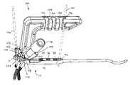
- FIG. 1is a side elevation of a fixation device according to the invention
- FIG. 2is a plan view of a fixation device according to the invention.
- FIG. 3is a bottom view of the plate-portion end of the fixation device of the invention.
- FIG. 4is a plate-portion end view of the fixation device of the invention.
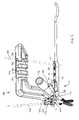
- FIG. 5is a perspective view of an implantation jig according to the invention coupled to the fixation device of the invention.
- a fracture fixation device 10includes a supra-metaphyseal plate portion 12 and an intracellular nail portion 14 which is horizontally and vertically offset relative to the plate portion by a neck portion 16 .
- the plate portion 12has a narrow profile and is slightly rounded about its upper surface 20 .
- the plate portion 12includes four longitudinally displaced fixed angle holes 22 , 24 , 26 , 28 , each preferably threaded, and each of which is adapted to lock a fastener, such as a smooth or threaded shaft peg 30 , in a different orientation from the others (i.e., the axes are oblique relative to each other).
- the pegs 30are laterally displaced defining an imaginary surface (generally transverse to the longitudinal axis A of the plate portion) which generally corresponds to (i.e., extends parallel to) the articular surface of the subchondral bone.
- the plate portion 12includes a dimple 32 for referencing an implantation jig, as described below.
- the nail portion 14includes three threaded screw holes 34 , 36 , 38 oriented normal to a preferably flattened endosteal surface 40 , and a smaller K-wire alignment hole 42 parallel to the screw holes and sized to closely receive a K-wire at a fixed angle.
- the tail end 44 of the nail portion 14is provided with a portion 46 having downward and then upward curve which facilitates maneuvering the tail end of the nail portion through the intrafocal space and into the medullary canal.
- an implantation jig 100 for the fixation devicehas a first portion 102 seatable on the plate portion 12 of the fixation device, and a relatively elevated second portion 104 in alignment over the screw holes 34 , 36 , 38 of the intracellular nail portion 14 of the fixation device 10 .
- the first portion 102includes a lower nub (not shown) which seats in the dimple 32 ( FIG. 2 ) on the plate portion 12 of the fixation device.
- the first portionincludes access openings 106 (at the front), 110 (at the left side, and at right the side, not shown), 108 (at the rear) in axial alignment with the fixed angle screw holes 22 , 24 , 26 , 28 .
- Such openingsare preferably initially positioned over drill guide tips (not shown) which are inserted in all of the fixed angle holes of the plate portion but the hole beneath access opening 110 .
- the drill guide tipswhich functions as miniature drill guides, are described in detail in co-owned U.S. Ser. No. 11/011,917, filed Dec. 14, 2004, which is hereby incorporated by reference herein in its entirety.
- the drill guides tipsare not necessitated, and individual drill guides can be inserted into the fixed angle holes just prior to drilling holes into bone in alignment with the holes.
- a cannulated locking drill guide 116 having a threaded end 118is provided through opening 110 and thread into hole 26 in the plate portion 12 , such that a portion of the guide 116 applies a force against said jig 100 .
- the locking drill guide 116in conjunction with the engagement of the nub within the dimple 32 immobilizes the jig 100 relative to the fixation device 10 so that the two are fixed relative to each other.
- the back 120 of the first portion 102 of the jig 100is curved upward to facilitate maneuvering the nail portion 14 of the fixation device within the intrafocal space and to allow the first portion to rest on the diaphyseal-side of the fracture (e.g., the proximal cortex of the distal radius) during the implantation process.
- the diaphyseal-side of the fracturee.g., the proximal cortex of the distal radius
- the first portion 102 of the jig 100includes two K-wire guide holes 122 , 124 which extend on either side of the front of the plate portion when the jig 100 is fixed relative to the fixation deice 10 to guide a K-wire offset relative to the plate portion.
- the K-wire guide holes 122 , 124are designed to closely hold an appropriately sized K-wire 126 and direct it at a fixed angle parallel to the endmost screw hole 22 (e.g., distalmost where the fixation device is used at the distal radius).
- the endmost holes for left and right fixation deviceseach have opposite respective angles, and the same jig may be used with each of the left and right devices.
- the K-wire guide hole located opposite the side on which the locking drill guide is positionedis used. That is, as shown in FIG. 5 , with the locking drill guide on the left side of the plate, the right side K-wire guide hole 122 is used.
- the respective K-wire guide hole 122defines an axis which is laterally offset, substantially parallel to, and closely spaced to the axis of the endmost screw hole 22 (preferably within approximately 5 mm), thus anticipating the path of a peg through the endmost screw hole 22 .
- a K-wire 126is drilled into bone through the appropriate K-wire guide hole 122 and its placement within the bone is viewed under fluoroscopy to ensure its placement relative to the articular surface of the subchondral bone is appropriate. If correct, the screw holes can be drilled with assurance that the screws will not enter the articular space. If not correctly located as indicated by K-wire fluoroscopic visualization, the plate can be repositioned, the K-wire re-drilled and re-examined until placement is correct.
- the second portion 104 of the jigincludes longitudinally displaced holes or slots 130 , 132 , 134 , as described in detail in U.S. Pat. No. 6,926,720, to longitudinally align drill guides with the screw holes 34 , 36 , 38 of the intracellular portion 14 of the fixation device 10 .
- the second portion 104also includes a K-wire guide hole 136 configured to direct a K-wire 138 at a fixed angle into the K-wire alignment hole 142 of the nail portion of the fixation device.
- a K-wireis drilled through the K-wire guide hole in the second portion and its placement can be viewed under fluoroscopy to ensure its placement relative to the diaphysis is appropriate. If correct, the screw holes can be drilled with assurance that the screws will be properly aligned relative to the axis of the diaphysis. If not correctly aligned as indicated by fluoroscopic visualization, the nail portion can be repositioned, the K-wire re-drilled and re-examined until placement is correct.
- the jigis usable in combination with drill guides, bits and gauges as described in previously incorporated U.S. Pat. No. 6,926,720.
Landscapes
- Health & Medical Sciences (AREA)
- Orthopedic Medicine & Surgery (AREA)
- Surgery (AREA)
- Life Sciences & Earth Sciences (AREA)
- Heart & Thoracic Surgery (AREA)
- Veterinary Medicine (AREA)
- Engineering & Computer Science (AREA)
- Biomedical Technology (AREA)
- Nuclear Medicine, Radiotherapy & Molecular Imaging (AREA)
- Medical Informatics (AREA)
- Molecular Biology (AREA)
- Animal Behavior & Ethology (AREA)
- General Health & Medical Sciences (AREA)
- Public Health (AREA)
- Neurology (AREA)
- Dentistry (AREA)
- Oral & Maxillofacial Surgery (AREA)
- Surgical Instruments (AREA)
Abstract
Description
Claims (14)
Priority Applications (1)
| Application Number | Priority Date | Filing Date | Title |
|---|---|---|---|
| US11/342,114US7686808B2 (en) | 2006-01-27 | 2006-01-27 | Fracture fixation device and implantation jig therefor |
Applications Claiming Priority (1)
| Application Number | Priority Date | Filing Date | Title |
|---|---|---|---|
| US11/342,114US7686808B2 (en) | 2006-01-27 | 2006-01-27 | Fracture fixation device and implantation jig therefor |
Publications (2)
| Publication Number | Publication Date |
|---|---|
| US20070191855A1 US20070191855A1 (en) | 2007-08-16 |
| US7686808B2true US7686808B2 (en) | 2010-03-30 |
Family
ID=38369680
Family Applications (1)
| Application Number | Title | Priority Date | Filing Date |
|---|---|---|---|
| US11/342,114Expired - Fee RelatedUS7686808B2 (en) | 2006-01-27 | 2006-01-27 | Fracture fixation device and implantation jig therefor |
Country Status (1)
| Country | Link |
|---|---|
| US (1) | US7686808B2 (en) |
Cited By (21)
| Publication number | Priority date | Publication date | Assignee | Title |
|---|---|---|---|---|
| US7896886B2 (en) | 2005-01-28 | 2011-03-01 | Depuy Products, Inc. | Nail plate and implantation jig therefor |
| US7938850B2 (en) | 2002-05-30 | 2011-05-10 | Depuy Products, Inc. | Nail plate |
| US20110118740A1 (en)* | 2009-11-10 | 2011-05-19 | Illuminoss Medical, Inc. | Intramedullary Implants Having Variable Fastener Placement |
| US8591554B2 (en) | 2010-05-07 | 2013-11-26 | Osteomed Llc | System for treating bone fractures |
| US9023051B2 (en) | 2011-02-22 | 2015-05-05 | Zimmer Knee Creations, Inc. | Navigation and positioning systems and guide instruments for joint repair |
| US9089375B2 (en) | 2013-10-12 | 2015-07-28 | Interfix, Llc | Combined intramedullary and extramedullary surgical aiming system and method |
| USD779065S1 (en) | 2014-10-08 | 2017-02-14 | Nuvasive, Inc. | Anterior cervical bone plate |
| US9833270B2 (en) | 2013-09-19 | 2017-12-05 | Mcginley Engineered Solutions, Llc | Variable angle blade plate system and method |
| US10251691B2 (en) | 2016-09-22 | 2019-04-09 | Globus Medical, Inc. | Systems and methods for intramedullary nail implantation |
| US10492803B2 (en) | 2016-09-22 | 2019-12-03 | Globus Medical, Inc. | Systems and methods for intramedullary nail implantation |
| US10682168B2 (en) | 2016-09-15 | 2020-06-16 | Wright Medical Technology, Inc. | Intramedullary implant with proximal plate and method for its use |
| US10751096B2 (en) | 2016-09-22 | 2020-08-25 | Bala Sundararajan | Systems and methods for intramedullary nail implantation |
| EP3751574A2 (en) | 2014-06-25 | 2020-12-16 | Canary Medical Inc. | Devices, systems and methods for using and monitoring orthopedic hardware |
| US10881436B2 (en) | 2017-10-27 | 2021-01-05 | Wright Medical Technology, Inc. | Implant with intramedullary portion and offset extramedullary portion |
| US11045242B2 (en) | 2016-09-22 | 2021-06-29 | Globus Medical, Inc. | Systems and methods for intramedullary nail implantation |
| US11083503B2 (en) | 2016-09-22 | 2021-08-10 | Globus Medical, Inc. | Systems and methods for intramedullary nail implantation |
| US11633219B2 (en) | 2019-06-26 | 2023-04-25 | Globus Medical, Inc. | Fenestrated pedicle nail |
| US11660201B2 (en) | 2018-10-25 | 2023-05-30 | Wright Medical Technology, Inc. | Systems, apparatuses, and methods for correcting a bone defect |
| US12138029B2 (en) | 2014-06-25 | 2024-11-12 | Canary Medical Switzerland Ag | Devices, systems and methods for using and monitoring spinal implants |
| EP4501218A2 (en) | 2014-09-17 | 2025-02-05 | Canary Medical Inc. | Devices, systems and methods for using and monitoring medical devices |
| US20250090204A1 (en)* | 2023-09-15 | 2025-03-20 | Globus Medical, Inc. | Targeted plate-nail constructs |
Families Citing this family (13)
| Publication number | Priority date | Publication date | Assignee | Title |
|---|---|---|---|---|
| US20070083202A1 (en)* | 2005-09-20 | 2007-04-12 | Donald Eli Running | Intramedullary bone plate with sheath |
| US10687869B2 (en)* | 2006-07-05 | 2020-06-23 | Advanced Orthopaedic Solutions, Inc. | Trochanteric nail with locking opening |
| US9615865B2 (en)* | 2007-05-04 | 2017-04-11 | George J. Haidukewych | Bone end (epiphysis) fracture fixation device and method of use |
| EP2072016B1 (en)* | 2007-12-17 | 2012-10-03 | Stryker Leibinger GmbH & Co. KG | Bone plate instrument and method |
| AU2009230888A1 (en)* | 2008-04-03 | 2009-10-08 | Austofix Group Limited | Tool jig for bone implant assembly |
| FR2948555B1 (en)* | 2009-07-28 | 2012-05-04 | D L P Sarl | INTRAMEDULAR NAIL |
| US8808340B1 (en) | 2010-04-30 | 2014-08-19 | SonicSurg Innovations, LLC | Device for repairing a bone fracture |
| US8403939B2 (en) | 2010-11-05 | 2013-03-26 | Biomet, C.V. | Surgical drill guide |
| US9050151B2 (en) | 2012-03-06 | 2015-06-09 | Stryker Trauma Sa | Bone plate and aiming block |
| US11051864B2 (en) | 2012-08-30 | 2021-07-06 | DePuy Synthes Products, Inc. | Intramedullary fixation assembly |
| CN107137134B (en)* | 2017-05-18 | 2023-04-07 | 唐佩福 | Combined fracture repositor |
| BR112020019260A2 (en) | 2018-05-31 | 2021-01-12 | Wright Medical Technology, Inc. | BONE FIXATION IMPLANT AND IMPLEMENTATION METHOD |
| CN114533235B (en)* | 2022-02-24 | 2022-12-02 | 中国人民解放军总医院第七医学中心 | Children epiphyseal plate damage fixing device that resets |
Citations (19)
| Publication number | Priority date | Publication date | Assignee | Title |
|---|---|---|---|---|
| US4465065A (en) | 1983-01-07 | 1984-08-14 | Yechiel Gotfried | Surgical device for connection of fractured bones |
| US5366457A (en) | 1991-12-13 | 1994-11-22 | David A. McGuire | Method and apparatus for preparing a bone and tendon graft |
| US5458654A (en) | 1993-07-14 | 1995-10-17 | Ao-Forschungsinstitut Davos | Screw-fixed femoral component for hip joint prosthesis |
| EP0737444A1 (en)* | 1995-04-13 | 1996-10-16 | France-Bloc | Patella cutting guide |
| US5658283A (en) | 1995-02-15 | 1997-08-19 | Huebner; Randall J. | External fixator for repairing fractures |
| US5853415A (en) | 1993-07-06 | 1998-12-29 | Zimmer, Inc. | Femoral milling instrumentation for use in total knee arthroplasty with optional cutting guide attachment |
| US5928234A (en) | 1997-10-10 | 1999-07-27 | Manspeizer; Sheldon | External fixture for tracking motion of a joint |
| US6514253B1 (en) | 2000-11-22 | 2003-02-04 | Meei-Huei Yao | Apparatus for locating interlocking intramedullary nails |
| US6527775B1 (en) | 2000-09-22 | 2003-03-04 | Piper Medical, Inc. | Intramedullary interlocking fixation device for the distal radius |
| US20030055428A1 (en) | 2001-09-12 | 2003-03-20 | Swanson Todd V. | Method and apparatus for treating supracondylar fractures of the femur |
| US20030083661A1 (en)* | 2000-02-01 | 2003-05-01 | Hand Innovations, Inc. | Intramedullary fixation device for metaphyseal long bone fractures and methods of using the same |
| US6579293B1 (en) | 2000-08-02 | 2003-06-17 | Rama E. Chandran | Intramedullary rod with interlocking oblique screw for tibio-calcaneal arthrodesis |
| US20030216742A1 (en) | 2002-02-13 | 2003-11-20 | Merrick Wetzler | Surgical drill guide |
| US6692496B1 (en) | 1998-11-02 | 2004-02-17 | Grampian University Hospitals Nhs Trust | Fracture treatment |
| US6746453B2 (en) | 2000-11-13 | 2004-06-08 | Benoist Girard Sas | Targeting apparatus for use in performing transfemoral osteotomy |
| WO2005053548A1 (en)* | 2003-12-03 | 2005-06-16 | Synthes Ag Chur | Device for repositioning bone fractures |
| US6926720B2 (en) | 2003-10-15 | 2005-08-09 | Hand Innovations, Llc | Jig assembly for implantation of a fracture fixation device |
| US20070173843A1 (en)* | 2005-12-22 | 2007-07-26 | Matityahu Amir M | Drug delivering bone plate and method and targeting device for use therewith |
| US20070173839A1 (en)* | 2006-01-10 | 2007-07-26 | Running Donald E | Fracture fixation plate with cover sheath |
- 2006
- 2006-01-27USUS11/342,114patent/US7686808B2/ennot_activeExpired - Fee Related
Patent Citations (20)
| Publication number | Priority date | Publication date | Assignee | Title |
|---|---|---|---|---|
| US4465065A (en) | 1983-01-07 | 1984-08-14 | Yechiel Gotfried | Surgical device for connection of fractured bones |
| US5366457A (en) | 1991-12-13 | 1994-11-22 | David A. McGuire | Method and apparatus for preparing a bone and tendon graft |
| US5853415A (en) | 1993-07-06 | 1998-12-29 | Zimmer, Inc. | Femoral milling instrumentation for use in total knee arthroplasty with optional cutting guide attachment |
| US5458654A (en) | 1993-07-14 | 1995-10-17 | Ao-Forschungsinstitut Davos | Screw-fixed femoral component for hip joint prosthesis |
| US5658283A (en) | 1995-02-15 | 1997-08-19 | Huebner; Randall J. | External fixator for repairing fractures |
| EP0737444A1 (en)* | 1995-04-13 | 1996-10-16 | France-Bloc | Patella cutting guide |
| US5928234A (en) | 1997-10-10 | 1999-07-27 | Manspeizer; Sheldon | External fixture for tracking motion of a joint |
| US6692496B1 (en) | 1998-11-02 | 2004-02-17 | Grampian University Hospitals Nhs Trust | Fracture treatment |
| US20030083661A1 (en)* | 2000-02-01 | 2003-05-01 | Hand Innovations, Inc. | Intramedullary fixation device for metaphyseal long bone fractures and methods of using the same |
| US6706046B2 (en) | 2000-02-01 | 2004-03-16 | Hand Innovations, Inc. | Intramedullary fixation device for metaphyseal long bone fractures and methods of using the same |
| US6579293B1 (en) | 2000-08-02 | 2003-06-17 | Rama E. Chandran | Intramedullary rod with interlocking oblique screw for tibio-calcaneal arthrodesis |
| US6527775B1 (en) | 2000-09-22 | 2003-03-04 | Piper Medical, Inc. | Intramedullary interlocking fixation device for the distal radius |
| US6746453B2 (en) | 2000-11-13 | 2004-06-08 | Benoist Girard Sas | Targeting apparatus for use in performing transfemoral osteotomy |
| US6514253B1 (en) | 2000-11-22 | 2003-02-04 | Meei-Huei Yao | Apparatus for locating interlocking intramedullary nails |
| US20030055428A1 (en) | 2001-09-12 | 2003-03-20 | Swanson Todd V. | Method and apparatus for treating supracondylar fractures of the femur |
| US20030216742A1 (en) | 2002-02-13 | 2003-11-20 | Merrick Wetzler | Surgical drill guide |
| US6926720B2 (en) | 2003-10-15 | 2005-08-09 | Hand Innovations, Llc | Jig assembly for implantation of a fracture fixation device |
| WO2005053548A1 (en)* | 2003-12-03 | 2005-06-16 | Synthes Ag Chur | Device for repositioning bone fractures |
| US20070173843A1 (en)* | 2005-12-22 | 2007-07-26 | Matityahu Amir M | Drug delivering bone plate and method and targeting device for use therewith |
| US20070173839A1 (en)* | 2006-01-10 | 2007-07-26 | Running Donald E | Fracture fixation plate with cover sheath |
Non-Patent Citations (2)
| Title |
|---|
| Article SCS/D "Distal Radius Plate System"; Avanta Orthopaedics 1997; 6 pgs. |
| Article: "The Hand Sourcebook" (Instruments for Surgeons) by K. Medic; dated 2002; 5 pgs. |
Cited By (43)
| Publication number | Priority date | Publication date | Assignee | Title |
|---|---|---|---|---|
| US7938850B2 (en) | 2002-05-30 | 2011-05-10 | Depuy Products, Inc. | Nail plate |
| US7896886B2 (en) | 2005-01-28 | 2011-03-01 | Depuy Products, Inc. | Nail plate and implantation jig therefor |
| US7927341B2 (en) | 2005-01-28 | 2011-04-19 | Depuy Products, Inc. | Nail plate and jig therefor |
| US20110118740A1 (en)* | 2009-11-10 | 2011-05-19 | Illuminoss Medical, Inc. | Intramedullary Implants Having Variable Fastener Placement |
| US9295506B2 (en) | 2010-05-07 | 2016-03-29 | Osteomed Llc | System for treating bone fractures |
| US8603148B2 (en) | 2010-05-07 | 2013-12-10 | Raymond B. Raven, III | System for treating bone fractures |
| US9066766B2 (en) | 2010-05-07 | 2015-06-30 | Osteomed Llc | System for treating bone fractures |
| US8591554B2 (en) | 2010-05-07 | 2013-11-26 | Osteomed Llc | System for treating bone fractures |
| US9649141B2 (en) | 2010-05-07 | 2017-05-16 | Mcginley Engineered Solutions, Llc | System for treating bone fractures |
| US10111688B2 (en) | 2010-05-07 | 2018-10-30 | Mcginley Engineered Solutions, Llc | System for treating bone fractures |
| US9023051B2 (en) | 2011-02-22 | 2015-05-05 | Zimmer Knee Creations, Inc. | Navigation and positioning systems and guide instruments for joint repair |
| US9775639B2 (en) | 2011-02-22 | 2017-10-03 | Zimmer Knee Creations, Inc. | Navigation and positioning systems and guide instruments for joint repair |
| US9833270B2 (en) | 2013-09-19 | 2017-12-05 | Mcginley Engineered Solutions, Llc | Variable angle blade plate system and method |
| US10117689B2 (en) | 2013-09-19 | 2018-11-06 | Mcginley Engineered Solutions, Llc | Variable angle blade plate system and method |
| US9089375B2 (en) | 2013-10-12 | 2015-07-28 | Interfix, Llc | Combined intramedullary and extramedullary surgical aiming system and method |
| US12138029B2 (en) | 2014-06-25 | 2024-11-12 | Canary Medical Switzerland Ag | Devices, systems and methods for using and monitoring spinal implants |
| EP3751574A2 (en) | 2014-06-25 | 2020-12-16 | Canary Medical Inc. | Devices, systems and methods for using and monitoring orthopedic hardware |
| US12419567B2 (en) | 2014-06-25 | 2025-09-23 | Canary Medical Switzerland Ag | Devices, systems and methods for using and monitoring orthopedic hardware |
| EP4501218A2 (en) | 2014-09-17 | 2025-02-05 | Canary Medical Inc. | Devices, systems and methods for using and monitoring medical devices |
| USD798455S1 (en) | 2014-10-08 | 2017-09-26 | Nuvasive, Inc. | Anterior cervical bone plate |
| USD779065S1 (en) | 2014-10-08 | 2017-02-14 | Nuvasive, Inc. | Anterior cervical bone plate |
| US12150681B2 (en) | 2016-09-15 | 2024-11-26 | Wright Medical Technology, Inc. | Intramedullary implant with proximal plate and method for its use |
| US11596457B2 (en) | 2016-09-15 | 2023-03-07 | Wright Medical Technology, Inc. | Intramedullary implant with proximal plate and method for its use |
| US10682168B2 (en) | 2016-09-15 | 2020-06-16 | Wright Medical Technology, Inc. | Intramedullary implant with proximal plate and method for its use |
| US10492803B2 (en) | 2016-09-22 | 2019-12-03 | Globus Medical, Inc. | Systems and methods for intramedullary nail implantation |
| US12178489B2 (en) | 2016-09-22 | 2024-12-31 | Globus Medical, Inc. | Systems and methods for intramedullary nail implantation |
| US11083503B2 (en) | 2016-09-22 | 2021-08-10 | Globus Medical, Inc. | Systems and methods for intramedullary nail implantation |
| US11090098B2 (en) | 2016-09-22 | 2021-08-17 | Globus Medical, Inc. | Systems and methods for intramedullary nail implantation |
| US11490905B2 (en) | 2016-09-22 | 2022-11-08 | Globus Medical, Inc. | Systems and methods for intramedullary nail implantation |
| US11045242B2 (en) | 2016-09-22 | 2021-06-29 | Globus Medical, Inc. | Systems and methods for intramedullary nail implantation |
| US10251691B2 (en) | 2016-09-22 | 2019-04-09 | Globus Medical, Inc. | Systems and methods for intramedullary nail implantation |
| US12285178B2 (en) | 2016-09-22 | 2025-04-29 | Globus Medical, Inc. | Systems and methods for intramedullary nail implantation |
| US11730524B2 (en) | 2016-09-22 | 2023-08-22 | Globus Medical, Inc. | Systems and methods for intramedullary nail implantation |
| US10299847B2 (en) | 2016-09-22 | 2019-05-28 | Globus Medical, Inc. | Systems and methods for intramedullary nail implantation |
| US10751096B2 (en) | 2016-09-22 | 2020-08-25 | Bala Sundararajan | Systems and methods for intramedullary nail implantation |
| US10307197B2 (en) | 2016-09-22 | 2019-06-04 | Globus Medical, Inc. | Systems and methods for intramedullary nail implantation |
| US10881436B2 (en) | 2017-10-27 | 2021-01-05 | Wright Medical Technology, Inc. | Implant with intramedullary portion and offset extramedullary portion |
| US11813003B2 (en) | 2017-10-27 | 2023-11-14 | Wright Medical Technology, Inc. | Implant with intramedullary portion and offset extramedullary portion |
| US12364523B2 (en) | 2017-10-27 | 2025-07-22 | Wright Medical Technology, Inc. | Implant with intramedullary portion and offset extramedullary portion |
| US12419672B2 (en) | 2017-10-27 | 2025-09-23 | Wright Medical Technology, Inc. | Implant with intramedullary portion and offset extramedullary portion |
| US11660201B2 (en) | 2018-10-25 | 2023-05-30 | Wright Medical Technology, Inc. | Systems, apparatuses, and methods for correcting a bone defect |
| US11633219B2 (en) | 2019-06-26 | 2023-04-25 | Globus Medical, Inc. | Fenestrated pedicle nail |
| US20250090204A1 (en)* | 2023-09-15 | 2025-03-20 | Globus Medical, Inc. | Targeted plate-nail constructs |
Also Published As
| Publication number | Publication date |
|---|---|
| US20070191855A1 (en) | 2007-08-16 |
Similar Documents
| Publication | Publication Date | Title |
|---|---|---|
| US7686808B2 (en) | Fracture fixation device and implantation jig therefor | |
| US20060149257A1 (en) | Fracture fixation device | |
| US20060161156A1 (en) | Fracture fixation device | |
| US6706046B2 (en) | Intramedullary fixation device for metaphyseal long bone fractures and methods of using the same | |
| US7001388B2 (en) | System for stabilization of fractures of convex articular bone surfaces including subchondral support structure | |
| EP2227160B1 (en) | Distal tibia plating system | |
| US6730090B2 (en) | Fixation device for metaphyseal long bone fractures | |
| EP1723920A2 (en) | Bone fixation system | |
| EP1723917A1 (en) | Apparatus for bone fastener implantation | |
| IL193043A (en) | Fracture fixation device and implantation jig therefor | |
| US20120016366A1 (en) | Proximal Radius Locking Plate | |
| AU2003234384B2 (en) | Intramedullary fixation device for metaphyseal long bone fractures |
Legal Events
| Date | Code | Title | Description |
|---|---|---|---|
| AS | Assignment | Owner name:DEPUY PRODUCTS, INC., INDIANA Free format text:ASSIGNMENT OF ASSIGNORS INTEREST;ASSIGNORS:ORBAY, JORGE L.;CASTANEDA, JAVIER E.;MEBARAK, EDWARD;REEL/FRAME:017345/0066 Effective date:20060127 Owner name:DEPUY PRODUCTS, INC.,INDIANA Free format text:ASSIGNMENT OF ASSIGNORS INTEREST;ASSIGNORS:ORBAY, JORGE L.;CASTANEDA, JAVIER E.;MEBARAK, EDWARD;REEL/FRAME:017345/0066 Effective date:20060127 | |
| STCF | Information on status: patent grant | Free format text:PATENTED CASE | |
| AS | Assignment | Owner name:BIOMET C.V., GIBRALTAR Free format text:ASSIGNMENT OF ASSIGNORS INTEREST;ASSIGNOR:DEPUY PRODUCTS, INC.;REEL/FRAME:029683/0912 Effective date:20120612 | |
| FPAY | Fee payment | Year of fee payment:4 | |
| MAFP | Maintenance fee payment | Free format text:PAYMENT OF MAINTENANCE FEE, 8TH YEAR, LARGE ENTITY (ORIGINAL EVENT CODE: M1552) Year of fee payment:8 | |
| FEPP | Fee payment procedure | Free format text:MAINTENANCE FEE REMINDER MAILED (ORIGINAL EVENT CODE: REM.); ENTITY STATUS OF PATENT OWNER: LARGE ENTITY | |
| LAPS | Lapse for failure to pay maintenance fees | Free format text:PATENT EXPIRED FOR FAILURE TO PAY MAINTENANCE FEES (ORIGINAL EVENT CODE: EXP.); ENTITY STATUS OF PATENT OWNER: LARGE ENTITY | |
| STCH | Information on status: patent discontinuation | Free format text:PATENT EXPIRED DUE TO NONPAYMENT OF MAINTENANCE FEES UNDER 37 CFR 1.362 | |
| FP | Lapsed due to failure to pay maintenance fee | Effective date:20220330 |