US7686768B2 - Implantable pressure monitor - Google Patents
Implantable pressure monitorDownload PDFInfo
- Publication number
- US7686768B2 US7686768B2US11/452,920US45292006AUS7686768B2US 7686768 B2US7686768 B2US 7686768B2US 45292006 AUS45292006 AUS 45292006AUS 7686768 B2US7686768 B2US 7686768B2
- Authority
- US
- United States
- Prior art keywords
- pressure
- chip
- substrate
- sensor
- asic
- Prior art date
- Legal status (The legal status is an assumption and is not a legal conclusion. Google has not performed a legal analysis and makes no representation as to the accuracy of the status listed.)
- Active, expires
Links
Images


Classifications
- A—HUMAN NECESSITIES
- A61—MEDICAL OR VETERINARY SCIENCE; HYGIENE
- A61B—DIAGNOSIS; SURGERY; IDENTIFICATION
- A61B5/00—Measuring for diagnostic purposes; Identification of persons
- A61B5/02—Detecting, measuring or recording for evaluating the cardiovascular system, e.g. pulse, heart rate, blood pressure or blood flow
- A61B5/021—Measuring pressure in heart or blood vessels
- A61B5/0215—Measuring pressure in heart or blood vessels by means inserted into the body
- A—HUMAN NECESSITIES
- A61—MEDICAL OR VETERINARY SCIENCE; HYGIENE
- A61B—DIAGNOSIS; SURGERY; IDENTIFICATION
- A61B5/00—Measuring for diagnostic purposes; Identification of persons
- A61B5/0002—Remote monitoring of patients using telemetry, e.g. transmission of vital signals via a communication network
- A61B5/0031—Implanted circuitry
- A—HUMAN NECESSITIES
- A61—MEDICAL OR VETERINARY SCIENCE; HYGIENE
- A61B—DIAGNOSIS; SURGERY; IDENTIFICATION
- A61B5/00—Measuring for diagnostic purposes; Identification of persons
- A61B5/68—Arrangements of detecting, measuring or recording means, e.g. sensors, in relation to patient
- A61B5/6846—Arrangements of detecting, measuring or recording means, e.g. sensors, in relation to patient specially adapted to be brought in contact with an internal body part, i.e. invasive
- A61B5/6879—Means for maintaining contact with the body
- A61B5/6882—Anchoring means
- A—HUMAN NECESSITIES
- A61—MEDICAL OR VETERINARY SCIENCE; HYGIENE
- A61B—DIAGNOSIS; SURGERY; IDENTIFICATION
- A61B2560/00—Constructional details of operational features of apparatus; Accessories for medical measuring apparatus
- A61B2560/02—Operational features
- A61B2560/0204—Operational features of power management
- A61B2560/0214—Operational features of power management of power generation or supply
- A61B2560/0219—Operational features of power management of power generation or supply of externally powered implanted units
- A—HUMAN NECESSITIES
- A61—MEDICAL OR VETERINARY SCIENCE; HYGIENE
- A61B—DIAGNOSIS; SURGERY; IDENTIFICATION
- A61B2560/00—Constructional details of operational features of apparatus; Accessories for medical measuring apparatus
- A61B2560/02—Operational features
- A61B2560/0223—Operational features of calibration, e.g. protocols for calibrating sensors
- A—HUMAN NECESSITIES
- A61—MEDICAL OR VETERINARY SCIENCE; HYGIENE
- A61B—DIAGNOSIS; SURGERY; IDENTIFICATION
- A61B2562/00—Details of sensors; Constructional details of sensor housings or probes; Accessories for sensors
- A61B2562/02—Details of sensors specially adapted for in-vivo measurements
- A61B2562/0247—Pressure sensors
Definitions
- the inventionis directed generally to a method and apparatus and for sensing a characteristic of a patient, such as blood pressure and/or temperature, and more particularly to methods and devices particularly adapted for telemetric measurement of blood pressure via a device implanted within the cardiovascular system during surgery and particularly within the heart.
- Heart failureconstitutes “a new epidemic” in the USA.
- Heart failurea chronic, progressive and incurable disease, affects over 20 million people worldwide. In the US alone, some 5 million people have been diagnosed with heart failure. Heart failure is estimated to cost the US economy today more than $40 billion annually.
- Intracardiac pressure managementis an important aspect of heart failure treatment. For example, a rise of the intracardiac pressure, such as in the left atrium is an important early indication of disease progression and the first opportunity for therapeutic intervention.
- Current blood pressure-measuring methodsonly can be applied in the coronary care unit (CCU) or the intensive care unit (ICU) and provide no more than an occasional snapshot of intracardiac pressure when the patient is already in a very critical situation.
- CCUcoronary care unit
- ICUintensive care unit
- the limitations on current intracardiac pressure measurement methodsare a serious impediment to early and optimal treatment. Current treatment methods require hospitalization and may be extremely costly (on average, over $16,000 per patient admittance). The ability to monitor patients and intervene outside of the hospital setting would greatly reduce the number of hospitalizations and extend the lives of those affected by the diagnosis.
- the telemetric sensor described in U.S. Pat. No. 6,855,115can be implanted in the heart by a catheter and is not designed for surgical implantation.
- the sensorwhich is rolled up during the implantation procedure, must be made of a flexible material of a specific configuration so that any change of the blood pressure inside the heart effectuates a change in the distance of the sensor height, i.e., the distance between the two capacitor plates used in the sensor. This flexible sensor is folded for delivery via a catheter and then unfolded at the place of implantation.
- a disadvantage of such a configurationis its required flexibility as constant and precise acquisition of measurement data may not be possible when the sensor is placed on or close to the cardiac muscle, and therefore is exposed to the cardiac motions, which may influence correct pressure readings.
- the flexible material of a sensor made in accordance with U.S. Pat. No. 6,855,115may deform due to exposure to constantly streaming liquids, especially a turbulent blood stream likely encountered inside the heart. As a consequence, the capacitance of the capacitor may be changed and measurement values may deteriorate and/or deviate from the true value.
- Another disadvantage of this type of sensoris due to its use of a pressure-dependent LC-oscillator. The resonant frequency of this oscillator can be analyzed telemetrically.
- this kind of devicecan be applied to measure the pressure that affects the measurement capacitor.
- any damage to the materialcan affect the pressure measurements obtained.
- the sensoris influenced by the surrounding media of the sensor, a corruption of measurement values may occur.
- Another exemplary implantable deviceuses a catheter filled with a pressure transmitting fluid or gel-like material.
- the cathetertransmits pressure to a pressure transducer within a housing.
- the sensed pressureis then telemetrically transmitted to an external reader.
- a housingfor the electronic signal processing circuitry, which results in a larger and heavier sensor structure that can cause strain on the heart when implanted into a heart wall.
- the catheter and housing configurationcreates a more complicated, mechanical structure that may be at increased risk for mechanical failure, and therefore is not suitable for long term implantation.
- Another devicehas a pressure sensor placed within the heart.
- a signal from the pressure sensoris transmitted to a housing outside the heart which contains the electronic processing circuits.
- the signalis processed by the electronic processing circuits, such as converting the signals from analog to digital, and then telemetrically transmitted to an external reader.
- housing the electronic processing circuitryrequires additional components and a relatively larger implanted device.
- digitization of the signaldoes not occur until outside of the heart, there is a risk of interference in the wire connecting the sensor and the electronic processing circuitry, as analog interference may result from external sources.
- Small pressure sensor chips including the electronic processing circuitshave been used in other applications.
- integrated chips having pressure sensorshave been used for pressure measurement in optical and cranial applications. These sensors are compact and have fewer mechanical components. Examples of such pressure sensor chips are described in EP 1 312 302 A2 and German patent application DE 10 2004 005 220.7, of which the inventors of the present invention were involved.
- these integrated chipsare used in a relatively stable environment, with little movement in the fluids of the eye or brain.
- these pressure sensorssubject to the cyclical, dynamic movements found in the heart. Such movement may harm connections, such as connections between wires and the pressure sensing chip.
- the use of such pressure sensor chipsis not suited for the environment of the heart, where there is cyclical and dynamic movement, and where there is continuous and turbulent fluid movement around the pressure sensor.
- intra-cardiac pressure sensorsthat are more reliable and accurate, and which cause less irritation when implanted in the heart and are more compatible with the dynamic conditions encountered in a moving heart. Also, a need exists for such a sensor to be used at other locations within the cardiovascular system with little or no modifications.
- the inventionmeets the above needs and avoids the disadvantages and drawbacks of the prior art by providing a substantially rigid, chip-based telemetric sensor and system in which an extremely small and lightweight chip, including at least one pressure sensor and all necessary electrical circuitry, may be implanted into the heart or other portion of the cardiovascular system during surgery, to monitor blood pressure and/or temperature.
- pressure signalsmay be digitized at or near the sensing location in the heart or other location in the cardiovascular system and data may be telemetrically directed to the place of data acquisition to reduce or eliminate data transmission interference from external sources.
- the chipmay be a substantially rigid structure that provides improved durability, long term stability, and long term accuracy, and resistance to damage or a change in membrane characteristics from the blood flow due to turbulences and the like within the bloodstream.
- the chipmay be an application specific integrated chip (ASIC) containing all the necessary sensing elements and digital signal processing electronics.
- ASICpreferably is very small and lightweight to avoid undue stress on the heart and is orientated within the body in a position to minimize turbulent flow and reactionary forces.
- the ASICmay be used with an antenna in the form of a coil created with very small dimensions. This minimal configuration of ASIC and coil may reduce and/or eliminate mechanical tensions effecting the connection between ASIC and a coil.
- the ASIC and the coilmay be electrically and physically connected by a flexible coil.
- the ASIC, cable and coilmay be encapsulated within a seamless biocompatible and flexible sheathing, such as silicone or similar material, to form an integrated sensor unit.
- the seamless sheathingmay maintain the integrity of the sensor by reducing or eliminating the exposure of the sensor to body fluids, such as blood. It may also be shaped and/or orientated to reduce turbulent flow.
- a liquid or gelmay be placed between the pressure sensing elements, such as capacitive membrane sensors of the sensor and the sheathing, to reduce or eliminate the effects of endothelialization on the surface of the sensor.
- the sheathing materialitself may act as a pressure transmitting material.
- the liquid or gelallows for integrating the pressure across the entire area of pressure sensing portion of the sensor to minimize the effects of localized plaque or endothelialization.
- heparin and other preventative coatings known in the artalso may be used to prevent or reduce endothelialization.
- the sensor designmay have a unique geometry.
- the ASICmay be connected to a substantially rigid substrate in a spaced apart relationship from the ASIC such that the substrate is opposite the pressure sensing elements of the sensor chip, with an aperture in the substrate providing access to the pressure elements to expose them to fluid pressure to be sensed.
- a silicone or other similar flexible materialmay be disposed between the ASIC and the substrate.
- a pressure transmitting materialmay be placed within the gap between the ASIC and the rigid substrate so that pressure from the blood can be transmitted to the pressure elements via the material.
- the ASICmay incorporate a robust system to compensate for drift due to the age and use of the sensor.
- the ASICmay include inactive pressure sensing elements that determine the change in the measurement in the sensor due to age and usage, and may account for this change when active pressure sensing elements determine the pressure.
- the ASICmay be supported in a holder particularly adapted for anchoring the ASIC in a wall of the heart or other location in the cardiovasculature.
- the holdermay include a stop to position the ASIC and limit its movement.
- the ASICis powered by induction from a wireless signal from an external reader, thereby avoiding the need for an internal power source.
- Use of a transponder power supply at the external readerallows for a substantially rigid sensor device with a longer life.
- the external readerprovides power to the substantially rigid sensor and receives pressure and temperature information from the substantially rigid sensor.
- the external readerstores and displays measurement and parameter data, calculates certain values.
- the external readerstores and displays measurement and parameter data, and may transmit the data to a computer or other device for further processing.
- the external readermay have a separate antenna coil to facilitate prolonged periods on a patient's body.
- the external readermay store one or more calibration curves for different sensors.
- the telemetric pressure and/or temperature sensor of the inventionmay be used for continuous or on demand sensing.
- a specific identification numbermay be transmitted with each single measurement or measurement cycle. In this way, a continuous measurement value and sensor identification, and therefore the measurement value and the identity of the patient, is provided.
- the identification numbermay allow a single external reader to receive data from multiple sensors and systems and to assign them to the correct calibration curve for that sensor system and the patient.
- the integrated chipmay include a first substantially rigid substrate, at least one pressure sensor disposed within the substrate to generate signals indicative of a sensed pressure, and electronic signal processing components to process the signals generated by the at least one pressure sensor.
- the electronic signal processing componentsmay be operatively connected to the antenna and the integrated chip may be powered by a signal received at the antenna.
- An implantable holdermay support the integrated chip and include an anchor structure to mount the integrated chip within a wall of the heart during surgery such that the at least one pressure sensor is exposed to blood flow in the heart.
- the systemmay also include a remote receiver, wherein the integrated chip is operative to send digital signals indicative of the pressure sensed in the heart telemetrically via the antenna to the remote receiver.
- the at least one pressure sensormay be capacitive-based pressure sensitive membranes housed within the substrate.
- the at least one pressure sensormay generate an analog signal in response to a sensed pressure and the electronic signal processing components may include at least one analog to digital (A/D) converter to digitize within the heart the analog signals from the at least one pressure sensor.
- the systemmay further include a flexible wire connecting the antenna and the integrated circuit, with the antenna being configured to be implanted within the patient underneath the skin to facilitate telemetric data transmission to the receiver.
- the integrated chipmay weigh less than about one gram, have a surface area on one side of less than or equal to about 10 mm 2 and have a thickness of less than about 1 mm.
- the antenna, the chip, wire and holdermay be encapsulated in a seamless, one-piece biocompatible sheathing.
- a pressure transferring mediummay be interposed between the biocompatible sheathing and the at least one pressure sensor.
- the biocompatible sheathingmay act as the pressure transferring medium, and may be shaped to minimize turbulence in blood flow within the heart.
- the integrated chipmay further include a unique digital identification, which is sent telemetrically to the receiver.
- the receivermay obtain calibration information associated with the integrated chip based on the unique digital identification.
- the receivermay include a stored parameter and produce an alert based on the signals indicative of the pressure sensed in the heart and of the stored parameter.
- the systemmay further include a second substantially rigid substrate located opposite the at least one pressure sensor in the first substrate and in a spaced apart configuration to protect the chip from mechanical damage.
- the second substratemay include an aperture permitting blood flow within the heart to act on the at least one pressure one pressure sensor.
- a pressure transferring mediummay be interposed between the at least one pressure sensor and the second substantially rigid substrate to transfer blood pressure to the at least one pressure sensor.
- At least one bond padmay be disposed between the first and second substantially rigid substrates and electrically connected to the integrated chip.
- At least one bond tackmay be provided on the second substantially rigid substrate and be connected to the at least one bond pad such that the antenna is operatively connected to the integrated chip via the at least one bond pad and the at least one bond tack to provide a strain relief connection.
- An antenna connectormay connect the antenna to the second substantially rigid substrate, wherein the antenna connector includes a signal portion electrically connecting the antenna to the integrated chip and a support portion connected to the second substantially rigid substrate.
- the antenna connectormay be attached to the second substantially rigid substrate such that there is slack in the signal portion when the support portion is taut.
- the signal portionmay be connected to the integrated chip via the at least one bond tack and the support portion may be connected to the second substantially rigid substrate via an opening in the second substantially rigid substrate.
- the at least one bond tackmay include at least two bond tacks disposed on opposite sides of the aperture.
- the second substantially rigid substratemay include a protective barrier connected thereto, and a biocompatible sheathing may encapsulate at least the integrated chip and the second substantially rigid substrate. The protective barrier prevents the first substantially rigid substrate from puncturing the biocompatible sheathing.
- a flexible support materialmay be provided between the integrated chip and the second substantially rigid substrate.
- the holder and the first substantially rigid substratemay be integrally formed into a single piece.
- the antennamay be supported by said holder.
- the holdermay include a stop that limits the movement of the integrated chip into the heart chamber.
- the integrated chip and the holdermay be removable from the heart after implantation.
- the at least one pressure sensormay include a plurality of pressure sensors including at least one active sensor responsive to changes in pressure within the heart and at least one passive sensor that is isolated from the changes in pressure within the heart, and the electronic signal processing components may provide a signal based at least in part on a signal from the at least one active pressure sensor and a signal from the at least one passive pressure sensor.
- the structure of the active pressure sensormay be substantially the same as a structure of the passive pressure sensor.
- the plurality of pressure sensorsmay include capacitive pressure sensors each having a flexible movable membrane.
- the passive pressure sensor signalmay be responsive to a change in position of the membrane of the passive pressure sensor, which is due to a drift effect comprising a sag of said membrane.
- the change of position of the membrane of the active pressure sensormay be due to a change in pressure within the heart and a drift effect comprising a sag of the membrane.
- the pressure signalsmay be the result of offsetting the signal from the at least one active pressure sensor with the signal from the at least one passive pressure sensor.
- a method of sensing blood pressure within the cardiovascular system of a subjectincludes the steps of (a) implanting within the subject an integrated chip including a substantially rigid substrate and at least one capacitive-based pressure sensor disposed within said substrate in a position to sense blood pressure within the cardiovascular system; (b) powering on the integrated chip telemetrically by activating a power source located outside the subject; (c) obtaining one or more analog signals from the at least one pressure sensor indicative of the pressure at the position in the cardiovascular system; and (d) converting the analog signals to digital signals at or directly adjacent to the position in the cardiovascular system where the sensing occurs.
- the implanting stepmay include implanting an ASIC having a capacitive-based pressure sensor in the heart.
- the methodmay further include the step of limiting the ASIC from entering the heart chamber with a stop device.
- the integrated chipmay include a unique digital identification, and the method may include the step of telemetrically communicating the unique digital identification to an external reader.
- the methodmay further include the step of obtaining calibration information associated with the integrated chip at the external reader based on the unique digital identification.
- the integrated chipmay be supported in a holder and the implanting step may include the steps of delivering the holder to the position in the cardiovascular system, and mounting the holder at the position such that the at least one pressure sensor is exposed to the pressure in the cardiovascular system to be sensed.
- the at least one capacitive-based pressure sensormay include a plurality of capacitive-based pressure sensors including an active pressure sensor and a passive pressure sensor located within the subject in a position to directly sense blood-pressure within a position in the cardiovascular system, and the step of obtaining one or more analog signals may further include obtaining one or more analog signals from the active pressure sensor indicative of the pressure at the position in the cardiovascular system, obtaining one or more analog signals from the passive pressure sensor indicative of the pressure at the position in the cardiovascular system, and generating one or more combined analog signals based on the one or more analog signals from the active pressure sensor and the one or more analog signals from the passive pressure sensor indicative of the pressure at the position in the cardiovascular system.
- the step of converting the analog signalsmay further include converting the combined analog signals to digital signals.
- the step of generating the one or more combined analog signalsmay include offsetting the signal from said active pressure sensor with the signal from said passive pressure sensor.
- an integrated chip for intra-cardiac blood pressure measurement inside the heart of a patientincludes a first substantially rigid substrate, at least one pressure sensor disposed within the substrate to generate signals indicative of a sensed pressure, and electronic signal processing components to process the signals generated by the at least one pressure sensor.
- the electronic signal processing componentsmay be operatively connected to an antenna, and the integrated chip may be powered by a signal received at the antenna.
- the integrated chipis operative to send digital signals indicative of the pressure sensed in the heart telemetrically via an antenna to a remote receiver.
- the at least one pressure sensormay generate analog signals and the electronic signal processing components may include at least one analog to digital (A/D) converter to digitize within the heart the analog signals from the at least one pressure sensor.
- the integrated chipmay weigh less than about one gram, have a surface area on one side of less than or equal to about 10 mm 2 and have a thickness of less than about 1 mm.
- the integrated chipmay further include a second substantially rigid substrate located opposite the at least one pressure sensor in the first substrate and in a spaced apart configuration.
- the second substratemay include an aperture permitting blood pressure within the heart to act on the at least one pressure one pressure sensor.
- the integrated chipmay also include a pressure transferring medium interposed between the at least one pressure sensor and the second substantially rigid substrate to transfer blood pressure to the at least one pressure sensor.
- FIG. 1schematically illustrates an embodiment of an implantable telemetric measuring device and reader constructed according to principles of the invention providing for continuous or regular intra-cardiac pressure monitoring;
- FIG. 2schematically illustrates another embodiment of an implantable telemetric measuring device and reader constructed according to principles of the invention providing for on-demand intra-cardiac pressure monitor monitoring;
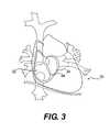
- FIG. 3illustrates a cross-sectional view of the heart area of a patient where the implanted device of the invention may be employed, including the left and right atrium and the crossing of veins at the posterior septum;
- FIG. 4illustrates a greatly enlarged, plan view of a substantially rigid ASIC constructed according to principles of the invention for sensing intra-cardiac pressure and temperature including active and passive, capacitive membrane sensing elements and on-chip electronics for digital signal processing and telemetrical power supply.
- FIG. 5is an enlarged, cross-sectional view of the ASIC of the invention showing some of the active pressure sensors and passive pressure sensors;
- FIG. 6is an enlarged, cross-sectional view of the ASIC of the invention showing a pressure transmitting gel or fluid between a sheathing and the active pressure sensors;
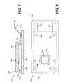
- FIGS. 7 and 8schematically illustrate a cross-sectional and top plan view, respectively, of one embodiment of an implantable sensor device of the invention including a substantially rigid ASIC connected at two ends to a substantially rigid substrate having a cut out;
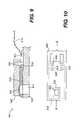
- FIGS. 9 and 10schematically illustrate a cross-sectional and top plan view, respectively, of another embodiment of an implantable sensor device of the invention including a substantially rigid ASIC connected at one end to a substrate having a cut out;
- FIG. 11is a perspective illustration of the implantable device of FIGS. 7 and 8 or 9 and 10 , showing an electrical wire and filament core connection between the ASIC and the antenna;
- FIG. 12illustrates a perspective view of the implantable sensor device of the invention with a cut out located at an edge of the substrate
- FIG. 13is a perspective view showing the electrical wire and filament core connection of the FIG. 12 embodiment
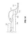
- FIG. 14is a cross-sectional view that schematically illustrates the electrical wire and filament core connection to a substrate of the invention.
- FIGS. 15 and 16schematically illustrate yet another embodiment of an implantable sensor device of the invention having a cut out located at an edge of the substantially rigid substrate and a protective barrier wall located at one end;
- FIG. 17schematically illustrates a cross section view of a further embodiment of the protective barrier wall of the invention.
- FIG. 18schematically illustrates an integrally formed ASIC and holder of the invention implanted in a wall of the heart during surgery
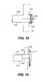
- FIG. 19schematically illustrates another integral ASIC and holder of the invention having a “T”-shaped anchor implanted in a wall of the heart during surgery;
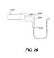
- FIG. 20schematically illustrates an ASIC and separately formed holder of the invention in the form of an elbow connector holding the ASIC and guiding a slack portion of the connecting wire;
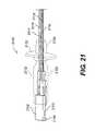
- FIG. 21is a three-dimensional representation of a holder of the invention that mounts the ASIC in the wall of the heart and includes suture wings that limit movement of the ASIC and serve as suture mounts;
- FIG. 22is a three-dimensional representation of another embodiment of a holder of the invention where the holder includes an end cap;
- FIG. 23is a three-dimensional representation of a holder of the invention illustrating how it connects the ASIC via a flexible cable to an antenna;
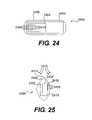
- FIG. 24schematically illustrates an implantable sensor device of the invention encased in a biocompatible sheathing
- FIG. 25is a side view of the device illustrated in FIG. 24 illustrating how the shape of the sensor may be configured as a football shape to minimize turbulence and reactionary fluid forces in the heart;
- FIG. 26is a side view of a dual substrate sensor device of the invention showing how the shape of the sheathing may be configured to minimize turbulence and reactionary fluid forces in the heart;
- FIG. 27is a side view of another embodiment of the invention illustrating how the shape of the sheathing may be configured to minimize turbulence and reactionary fluid forces in the heart;
- FIG. 28is a block diagram of the major electronic components of an external reader constructed according to the principles of the invention for telemetrically receiving data from an implanted sensor device.
- FIG. 1schematically illustrates an embodiment of an implantable telemetric measuring device and reader constructed according to principles of the invention providing for continuous or regular intra-cardiac pressure monitoring.
- a coil or antenna 14 connected with an external reader 12generates a radio frequency (RF) field in a manner known in the art.
- the coil 14 and external reader 12may be fixed to individual belts that wrap around the patient and connect to each other via a standard cable.
- the RF fieldinduces a current in a coil 18 connected to a substantially rigid sensor device 20 , such as described herein, implanted within the heart 16 of the patient 10 , such as the septum or the wall of the left atrium, to sense pressure in the left atrium.
- the sensor device 20may consist of an application specific integrated circuit (ASIC) such as described herein, having power conditioning circuitry that detects when adequate power is being delivered and switches on sensing, analog-to-digital, and data processing circuits.
- the data processing circuitrysends the sensor data to the ASIC transmitter, which uses the coil 18 as an antenna.
- the coil 18telemetrically transmits, via signal 22 , the data to the antenna 14 of the external reader 12 .
- the external reader 12may provide secure reception and storage of pressure and temperature values, compare the pressure reading of the implanted device 20 to ambient pressure via an internal sensor in the reader, and deliver the intracardiac data to other devices, such as computers, personal digital assistants (PDAs), cell phones, etc., via standard protocols.
- PDAspersonal digital assistants
- the external reader 12may obtain data from the sensor device 20 at continuous or regular intervals.
- the external reader 12may continuously generate an RF signal to activate the sensor device 20 to obtain pressure and/or temperature readings (in order to describe even the waveform of the blood pressure, if desired by the doctor, the sensor device should take up to 100 or more measurements per second).
- the external reader 12may generate an RF signal at regular intervals (e.g., every half hour, once ever four hours, once a day) to activate the implanted rigid sensor device 20 to obtain pressure and/or temperature readings.
- FIG. 2schematically illustrates another embodiment of an implantable telemetric measuring device and reader, which may operate similarly to the FIG. 1 embodiment but provides for on demand intra-cardiac pressure monitoring according to principles of the invention.
- a coil 28 in a hand-held reader 26generates an RF field that induces a current in the coil 18 of the substantially rigid sensor device 20 implanted within the heart 16 of the patient 10 , as in the FIG. 1 embodiment.
- sensor device 20may include an ASIC that operates similarly to the FIG. 1 embodiment.
- power conditioning circuitry in the sensor device 20detects when adequate power is being delivered, and turns on the sensing, analog-to-digital, and data processing circuits.
- the data processing circuitrysends the sensor data to the ASIC transmitter, which uses the coil 18 as an antenna.
- the coil 18transmits, via signal 24 , the data to the antenna 28 of the hand-held reader 26 .
- the hand-held reader 26may be extendable to expose the antenna 28 and provides reception and storage of pressure and temperature values, and compares the implant's pressure reading to ambient pressure via an internal sensor in the readout device.
- the hand-held device 26may deliver the intracardiac data to other devices, such as computers, PDAs, cell phones, etc., via standard protocols.
- the reader unit 26may obtain data from the implanted sensor device 20 on demand.
- a usermay activate and cause the reader unit 20 to generate an RF signal by extending the top portion containing the antenna from the bottom portion of the reader unit housing to activate the implanted rigid sensor device 20 to obtain pressure and/or temperature readings.
- FIG. 3illustrates a cross-sectional view of the heart area of a patient where the implanted device may be employed, including the left and right atrium and the crossing of veins at the posterior septum.
- the heart 30has a right atrium 32 and a left atrium 34 , which are divided by the septum 36 .
- the implantable devicemay work as a short-term implant as well as a long-term implant, and may be implanted at the “Waterston's groove” near the access of the pulmonary vein or other locations chosen by a doctor.
- the implantable sensor device 20also may be designed to facilitate ready removal of the device if medically necessary. An embodiment of such a removable device is illustrated in FIG. 23 .
- FIG. 4illustrates a substantially rigid sensor ASIC constructed according to principles of the invention for sensing intra-cardiac pressure and temperature in any of the embodiments of the invention.
- the ASIC 400contains pressure sensing elements 402 , such as eight passive sensors 404 and eight active sensors 406 , temperature sensor 408 , an analog-to-digital (A/D) converter 410 , data transmission circuitry 412 , power conditioning circuitry including components such as smoothing and resonance capacitors (not shown), a digital state control 414 including a code redundancy check for secure data transmission and memory 416 , such as Electrically Erasable Read-Only Memory (EEPROM) cells, for unit identification, which are components known in the cart.
- EEPROMElectrically Erasable Read-Only Memory
- the ASIC 400should be an extremely small and lightweight chip to avoid placing undue stress on the heart and/or producing turbulent flow in the heart chamber(s).
- an ASIC particularly adapted for use in the embodiments described herein as being implanted during open chest surgeryshould weigh less than fractions of a gram, have a surface area of less than or equal to about 10 mm 2 per side, and a thickness of about 1 ⁇ 4 mm to about 1 mm.
- the ASICmay be about 2 mm wide by 5 mm long by about 250 to 800 microns thick. Other dimensions may also be used depending upon the particular application or location in the cardiovasculature where the sensing will occur and depending upon the delivery method.
- the dimensions of the ASIC 400may range from about 3 mm to about 8 mm long, about 0.6 mm to about 2.5 mm wide, and about 0.2 mm to about 1.3 mm high. Other dimensions, such as an ASIC that is substantially square, may also be used.
- the ASIC 400includes sixteen capacitive pressure sensors cells 402 , eight of which are active pressure sensors 406 and provide pressure data, and eight of which are passive pressure sensors 404 and act as an internal reference.
- the pressure sensor cells 402may include minute, flexible membranes that are housed within the substantially rigid ASIC structure as shown schematically in FIG. 5 .
- the active pressure sensors 406have flexible membranes 424 and passive pressure sensors 404 have flexible membranes 426 .
- the membranes 424 of the active pressure sensors 406are distortable based on the level of cardiac blood pressure.
- the distortionmay be mainly in a direction generally perpendicular to the planar top surface of the ASIC 400 .
- the distortionmay be determined based on capacitive measurements or by use of distension measuring tapes.
- the sixteen capacitive pressure sensing elements 402 of the ASIC 400may each be about 96 microns in diameter.
- the capacitance measured in the pressure sensors 402changes.
- the pressure sensors 402generate signals based on the change in capacitance, and thus indicative of the pressure in the heart.
- the signalspreferably are processed by components located in or on the ASIC 400 and transmitted to an external reader.
- the blood pressure measuring processmay be a capacitive pressure measurement process via measuring membranes 424 , 426 that are integrated into the ASIC 400 , such as the planar top surface of the chip as shown in FIG. 5 .
- the ASIC 400may have a substantially inflexible, substrate made of silicon that cannot be folded or rolled up.
- the thin, but mechanically inflexible substratecreates a mechanically stable device providing a substantially rigid structure to house the measuring membranes 424 , 426 as shown in FIG. 5 .
- Changes in the geometry of the ASIC 400such as twisting due to blood turbulences, may be avoided due to this substantially rigid, chip-based configuration, even when the ASIC 400 is exposed to turbulent, blood flow.
- the implanted ASIC 400provides a durable device capable of withstanding the internal environment of the heart and other locations in the cardiovasculature without producing dangerous stresses within the heart.
- Numerous small membranes 424 , 426 having relatively small dimensionsmay be used as capacitive pressure sensors. Such small dimensions may result in membranes 424 that are less vulnerable to mechanical forces, such as the force of blood flow within the heart, and therefore more reliable.
- the ASIC 400contains mechanical and electrical elements that are subject to wear and need drift compensation to obtain measurements of suitable quality and reliability for their intended cardiovascular uses.
- Drift in a sensormay occur as time passes and physical properties of the structure change. Over time and usage, changes in electronics in a chip may effect the measurements. Further, when a pressure sensor uses a membrane, the membrane may sag in the middle as it ages. The capacitance at the pressure sensor membrane varies based on the change in position of the pressure sensor membrane. These changes, unrelated to the change in blood pressure, may alter the true value of the measurements being sensed. Drift compensation is particularly important in an intra-cardiac long-term pressure sensor.
- the drift compensation scheme employed in ASIC 400should reduce or eliminate the effects of the change in the physical properties of the ASIC 400 .
- the drift of the pressure values obtained from the sensor structure 400may be minimized to a value of about 5.0 mmHg/year to about 2.5 mmHg/year or even smaller than 1 mmHg/year.
- a plurality of active sensors 406 and a plurality of passive sensors 404are provided, such as eight of each.
- the structure of the active sensors 406 and the structure of the passive sensors 404are identical.
- the membranes 424 of the active sensors 406are open to the sensing environment (e.g., a heart chamber) for sensing pressure, while the membranes 426 of the passive sensors 404 are isolated from the environment, e.g., by placing a glass layer 428 or other suitable material over the surface of the membrane 426 so that pressure in heart will not affect the passive sensors 404 .
- Both the active sensors 406 and passive sensors 404are affected substantially the same by age, usage and sagging and any other effects of the environment.
- the ASIC 400may determine how much of the change in position of the pressure sensor membrane 426 is effected by the age and sagging. The change in capacitance based on the change in position of the passive pressure sensor membrane 426 is determined. This amount is then used to offset the change capacitance measured in the active pressure sensor membrane 424 .
- This systemallows the change in capacitance due the pressure within the heart to be more accurately determined. Compensating for drift may allow a doctor or patient to better determine short term (e.g., days, weeks) trends in pressure within the patient, such as the heart.
- the implantable sensor devicewhich may include the ASIC 400 , a connector and an antenna, may be completely encapsulated within a seamless biocompatible sheathing (not shown in FIGS. 5-6 ).
- the material areas around the measuring membranes 424maintain their flexibility after encapsulation to allow transmission of the pressure to the measuring membranes 424 .
- the biocompatible sheathingwill be described in greater detail below.
- FIG. 6is a cross-sectional view of the ASIC 402 of the invention with a gel or fluid between a sheathing and the active pressure sensors 406 .
- a glass substrate 428 or other suitable materialisolates the passive pressure sensors 404 .
- a liquid or gelatinous pressure transmitting medium 432is used between sheathing 430 and the active pressure sensors 406 .
- this liquid or gelatinous medium 432may improve the measurement or reception of blood pressure values within the chamber to be sensed, e.g., within the left atrium. Even though fibrous tissue or plaque may grow in the area of the implant over time (e.g., months or years after the implantation), encapsulating the pressure sensors within a separate gel-filled membrane may allow reliable measurement values to still be obtained.
- endothelializationmay result in endothelia being deposited on the surface of the sensor structure. If endothelia and/or plaque are deposited on the surface of one of the active pressure sensors, or on the biocompatible sheathing at the surface of one of the active pressure sensors, pressure measurement readings may be adversely affected.
- One way to reduce such an effectis to coat the sheathing and/or sensors with a drug, e.g., heparin, to reduce or eliminate endothelia.
- a druge.g., heparin
- the surface of the active pressure sensors 406are coated with a gel or fluid 432 and encapsulated in the membrane 430 .
- endothelial growth or plaque on the membrane 430 directly over the surface of one of the active pressure sensors 406will have a reduced or negligible effect on the pressure sensor measurement, as the pressure is transmitted via the endothelial growth and the membrane 430 through the gel/fluid 432 to the active pressure sensors 406 .
- plaque growth and/or endothelialization on the entire surfacewould still allow pressure sensing measurements to be obtained, as the pressure exerted on the endothelia is transmitted via the gel/fluid 432 to the active pressure sensors 406 .
- the gel/fluid filled membrane 430may function to integrate the change in pressure over a larger area than the individual active pressure sensors 406 themselves. This minimizes the effects of endothelialization and/or plaque adherence to the sheathing 430 .
- sheathing 430is shown as only covering the gel/fluid 432 , it is understood that the sheathing 430 or other sheathings could cover part or all of sensor device 400 , as described below.
- the ASIC 400includes an A/D converter 410 .
- the pressure sensors 402provide analog signals indicative of the pressure in the heart.
- the A/D converter 410converts the signals from the pressure sensors 402 to digital signals.
- the transmission and digitizing of measurement values into appropriate signals in the inventionis preferably carried out within or very closely adjacent to the heart chamber or chambers to be sensed, such as the left and/or right atrium and/or the left or right ventricle, and most preferably are processed inside the ASIC 400 .
- Using a fully digital systemmay result in greater accuracy of the readout.
- the amplitude of the signalis proportional to the pressure reading provided by the sensors
- the value of pressure recorded by an external readerdepends upon the distance between body and reader.
- the distance from the body to readermust be very tightly controlled, or the accuracy of the system will suffer.
- the distance from body to readerhas little or no effect on the pressure value measurement received due to the use of a digital signal and to processing the signals at or very near the sensor. This may make the system more robust and accurate than analog systems.
- the fully digitized datacan be handled for more easily by data transmission systems, making the external readers compatible with computer, Internet and telemedicine interfaces.
- highly accurate pressure sensors and a 9-bit analog-to-digital convertermay impart high resolution to the sensing systems, where an accuracy of about +/ ⁇ 2 mm Hg or less may be achieved.
- digitization at the ASIC 400may avoid interference issues from other, unrelated RF sources.
- analog signalsare sent from the sensor to the antenna structure via a wire.
- the systemmay avoid analog interference that may be induced in the wire by external RF signals and noise, such as radio broadcasts, electronics, and the like.
- the ASIC 400measures pressure at the pressure sensing elements 402 and transfers the absolute pressure signals to an external reader.
- a pressure valueis calculated from the difference of absolute pressure value, measured with the ASIC 400 , and the atmospheric pressure surrounding the patient as is well-known in the art. This atmospheric pressure may be measured within the external reader, which is normally in the surrounding environment of the patient.
- the operation of the ASIC 400is based on the interaction between a connected antenna, such as shown in FIG. 23 , and an external reader according to well-known principles of transponder technology. Therefore, no internal power source is required.
- the ASIC 400 and the external readermay be tuned so that continuous measurements, e.g. up to 120 single measurements per second, may be processed and transmitted.
- the total systemmay be programmed so that measurements are taken and stored in given intervals or at defined time periods. Retrieval, monitoring, and recording of data may be possible at any time.
- the ASIC 400preferably consists of a single integrated chip. All relevant functions and components for the measuring process, digitizing, identification number transmission, power supply, and telemetric data transmission are integrated into the single integrated chip. As described above, the ASIC 400 may contain a specific identification number, as well as a chip specific calibration file and further circuit and storage components. Alternatively, the circuit components may also be placed on two or more chips, e.g. if sensing in separate locations is desired.
- the ASIC 400may be formed from a single complementary metal oxide semiconductor (“CMOS”) chip to produce a smaller implantable device then with other methods, and help minimize power use and maximize measurement accuracy reliability. Since the consumption of power produces heat, minimization of power may be desirable in implantation applications. In a one-chip solution, the ASIC 400 may be highly resistant to mechanical or electrical interference from the outside, as there is no interaction between multiple chips.
- CMOScomplementary metal oxide semiconductor
- the power consumption of the chipmay be low, so that if an increase of temperature occurs in the course of inductive/transponder related power insertion, difficulty in measuring or data transmission may be reduced or avoided.
- the optimized circuit designmay result in a very low power consumption, such as only about 210 microwatts at about 3 volts DC.
- the sampling ratemay be about 20 to about 120 Hz.
- the high integration factor of the logic circuit combined with the high speed of data transmissionmay allow the use of a very secure data transmission protocol, thereby addressing concerns of the regulatory authorities.
- An integrated temperature sensor 408may be provided in the ASIC 400 to allow for temperature sensing as shown in FIG. 4 .
- the temperature sensor 408may use the circuit in the ASIC 400 and base the temperature measurement on current characteristics within the circuit, thereby determining the temperature in the heart based on the temperature based current characteristics within the ASIC 400 .
- Each ASIC 400may be individually calibrated to determine its current characteristics (magnitude, frequency, etc.) at a given temperature (e.g., body temperature). As the temperature changes, the current characteristics within the ASIC 400 change. Using the information on the current characteristics and the specific calibration determination for the ASIC 400 , the temperature at a particular time can be determined based on current characteristics at that time.
- the raw pressure datamust be corrected for temperature and other external and/or internal influences, and calibration information, such as a calibration curve of the embedded chip, may be established for each ASIC 400 or system that implements an ASIC 400 .
- calibration informationsuch as a calibration curve of the embedded chip, may be established for each ASIC 400 or system that implements an ASIC 400 .
- Each ASICmay have a unique identification number to facilitate calibration and use of data as discussed below.
- the ASCI 400includes a data memory 416 , such as the EEPROM cells, in which the unique identification number may be stored. This identification number is transmitted telemetrically together with the measurement values. The identification number may be used to determine the appropriate calibration information for an ASIC 400 . Also, a single external reader may then be used to interrogate multiple implanted ASIC's, as described below.
- a data memory 416such as the EEPROM cells, in which the unique identification number may be stored. This identification number is transmitted telemetrically together with the measurement values. The identification number may be used to determine the appropriate calibration information for an ASIC 400 . Also, a single external reader may then be used to interrogate multiple implanted ASIC's, as described below.
- the unique identification numbermay be transmitted along with the sensor data to the external reader to allow the external reader to use the correct calibration information to calculate pressure and/or temperature.
- An external reader(as described in greater detail below), may have a memory to store calibration information for a number of ASICs 400 or systems that implement ASICs 400 .
- the appropriate calibration informationis associated the appropriate ASIC 400 or system via the identification number.
- the external readeraccesses the calibration information associated with the particular ASIC 400 or system that includes the particular ASIC 400 .
- the data received by the external readeris processed using the appropriate calibration information to achieve more accurate results.
- Each ASIC 400 and/or systemalso may be zeroed prior to implantation.
- the systemcompares the measured pressure to the pressure in a vacuum.
- the external readercompares the ambient pressure to the pressure in a vacuum.
- Pressure inside the heartis calculated by comparing the difference between the pressure measured inside the heart and the pressure measured outside the patient.
- Zeroing the ASIC 400 or the systemmay involve using the ASIC 400 system to measure the pressure outside the patient and comparing this measurement to the pressure obtained by another external device. The difference between these two readings may be stored with the calibration information associated with the ASIC 400 or system and used to adjust future pressure measurements by the ASIC 400 or system once it has been implanted to account for the difference.
- an external readermay be used for the power supply of the ASIC.
- This unitalso may be used for telemetric data acquisition.
- the range for telemetric power supply and data transmissionmay be from about 3 cm to about 35 cm or other ranges as can be readily determined by a skilled artisan. This range also may depend on the distance between the external reader and the implanted antenna and the size of the antennas
- Measurement dataare processed and preferably are digitized on the ASIC 400 for transmission from the sensor structure to the interior transponder coil.
- the transmission of the measurement data from the ASIC 400 to the interior transponder coilmay be realized via one or more electric conductors, preferably designed as flexible thin wires, embedded in silicone on other nonconducting material.
- Measurement dataare transmitted telemetrically from the interior transponder coil to the external reader.
- the external reader capacitiesmay be designed for an exterior supply of all power resources which are required for the continuous operation of ASIC 400 , including measurements and data transmission.
- the ASIC 400also includes a bidirectional power circuitry 424 for working with the reader to evaluate the strength of the signals sent between the reader and the ASIC 400 .
- the components in the bidirectional power circuitry 424interact with a reader to ensure that appropriate signal strength and data transmission is achieved. The interaction between the bidirectional power evaluation module 424 and the reader is described in greater detail below with respect to FIG. 28 .
- FIGS. 7 and 8schematically illustrate an embodiment of an implantable sensor device 700 of the invention including a substantially rigid sensor chip connected at two ends to a substantially rigid substrate 708 having a cut out.
- a sensor chip 702such as ASCI 400 , includes pressure sensing membranes 704 and four spaced chip bond pads 706 .
- a substantially rigid substrate 708 having an aperture 710 and bond tracks 712 connected to bond pads 706are also provided.
- the substrate 708is configured in a spaced apart relationship to the sensor chip 702 . More particularly, the aperture 710 of the substrate 708 is located substantially opposite of the capacitive pressure membranes 704 of the sensor chip 702 so pressure from the blood surrounding the device may be transmitted readily to the pressure membranes 704 .
- a pressure transferring material(not shown) may be located at the aperture 710 to ensure that pressure from the blood is transferred to the pressure membranes 704 .
- the sensor chip 702 and the substrate 708may be configured in a fixed relationship, so that the distance, or offset, between the sensor chip 702 and the substrate 708 does not change.
- the chip bond pads 706may be connected to the substrate bond pads 712 to fix the distance between the sensor chip 702 and the substrate 708 .
- the sensor chip 702 and the substrate 708both have four bond pads. However, it is understood that other amounts of bond pads may also be used.
- At least one of the substrate bond pads 712may be elongated in the form of a track to facilitate connection to an electrical wire 714 that connects to an antenna (not shown).
- Electrical wire 714is connected to the substrate bond pad 712 by any conventional method, such as by using heat and pressure. Connecting the electrical wire 714 to a substrate bond pad 712 , as opposed to being directly connected to chip 702 , may reduce or eliminate damage to or malfunction by the sensor chip due to the connection process.
- the electrical wire 714is electrically connected to the sensor chip 702 via the electrical connection between the substrate bond pad 712 and the chip bond pad 706 .
- FIGS. 9 and 10schematically illustrate another embodiment of an implantable sensor device including a substantially rigid sensor chip connected at one end to a substantially rigid substrate having a cut out.
- the device 900 of FIGS. 9 and 10has similar components and operation to the device 700 illustrated in FIGS. 7 and 8 .
- device 900has chip bond pads 906 located in generally close proximity to each other at one end of the sensor chip 902 .
- the substrate bond pads 912are generally located in close proximity to each other on the substrate 908 .
- This arrangement of chip bond pads 906 and substrate bond pads 912may reduce stress on the sensor chip 902 , as changes in the size of the substantially rigid substrate 908 , such as due to thermal expansion, may have less of an effect on the sensor chip 902 due to the location of the chip bond pads 906 on the sensor chip 902 .
- the device 900may further include a flexible filler material 916 located between the sensor chip 902 and the substrate 908 .
- the filler 916may be located throughout the area between the sensor chip 902 and the substrate 908 except at the aperture 910 that is opposite the capacitive pressure membranes 904 .
- Filler 916may be any flexible material that can provide support to reduce or eliminate movement in the offset direction between the sensor chip 902 and the substrate 908 .
- the filler 916may be the same material used to surround the implanted device 900 , such as a biocompatible material like silicone or other similar material.
- FIG. 11is a perspective illustration of an implantable sensor device such as the FIG. 7 and 8 or FIG. 9 and 10 embodiments showing the electrical wire and core filament connection to the ASIC and antenna.
- the device 1100includes a substantially rigid sensor chip 1102 having pressure membranes 1104 , and a substantially rigid substrate 1108 with an aperture 1110 exposing the pressure membranes 1104 .
- a pressure transmitting material 1112such as a liquid or gelatinous material, is located within the aperture 1110 to transmit pressure from the blood to the pressure membranes 1104 .
- the entire device 1100is enclosed by a biocompatible sheathing 1106 , such as silicone.
- the sheathing 1106can also be used as the pressure transmitting material 1112 within the aperture 1110 .
- Substrate 1108may further include connector holes 1120 for facilitating attachment of an antenna connector 1114 to the substrate 1108 and the sensor chip 1102 .
- the connector 1114includes electrical wires 1116 and a filament core 1118 , such as nylon.
- Electrical wires 1116which may be formed of gold cable, or other appropriate material, provide an electrical connection between the sensor chip 1102 and an antenna (not shown). Electrical power from the antenna may be conducted via the electrical wires 1116 to the sensor chip 1102 for powering the sensor chip 1102 to obtain measurements. Signals, such as pressure measurements and identification indicia, may be transmitted over the electrical wires 1116 from the sensor chip 1102 to the antenna for transmission to a reader.
- the filament core 1118provides strength to the connector 1114 to reduce or eliminate strain on the connection between the substrate bond pad (not shown) and the electrical wires 1116 .
- the filament coremay be made of nylon or other similar, synthetic flexible material that does not conduct electricity and has a low coefficient of thermal expansion. This connection will now be described in greater detail below with reference to the examples of FIGS. 12-14 .
- FIGS. 12 and 13illustrate an implantable sensor device 1200 with a cut out located at an edge of the substantially rigid substrate, including a cable and core filament connection, while FIG. 14 schematically illustrates the cable and core filament connection to the substrate.
- the implantable device 1200includes a substantially rigid sensor chip 1202 having pressure membranes 1204 .
- the capacitive pressure membranes 1204are located near the edge of one side of the sensor chip 1202 .
- the device 1200further includes a substantially rigid substrate 1208 having connector holes 1220 and a cut out 1210 opposite of the pressure membranes 1204 .
- a pressure transmitting material 1212is located within the cut out 1210 to transmit pressure from the blood to the pressure membranes 1204 .
- the device 1200is surrounded by a biocompatible sheathing 1206 , such as silicone. According to a preferred embodiment of the invention, the pressure transmitting material 1212 may be the same as the sheathing material 1206 .
- the device 1200further includes a connector 1214 which includes electrical wires 1216 and a filament core 1218 .
- the electrical wires 1216which may be formed of gold, or any other suitable similar material, connect to substrate bond pads 1222 , and the substrate bond pads 1222 are connected to chip bond pads 1224 . This results in an electrical connection between the electrical wires 1216 and the sensor chip 1202 .
- the filament core 1218may be attached directly to the substrate 1208 , such as by an adhesive. As shown in FIG. 14 , the filament core 1218 is threaded through the connector hole 1220 for attachment to the substrate 1208 such that the electrical wires 1216 have extra slack when the filament core 1218 is pulled straight. This configuration may reduce or eliminate the strain on the connection between the electrical wires 1216 and the substrate bond pad 1222 when there is movement of either the connector 1214 or the substrate 1208 . Other methods for strain relief on electrical wires 1216 may also be used.
- FIGS. 15 and 16schematically illustrate an implantable sensor device with a cut out located at an edge of the substrate and a protective barrier wall located at one end of the substrate.
- the device 1500has a substantially rigid sensor chip 1502 having capacitive pressure membranes 1504 (shown in FIG. 16 ).
- the device 1500further includes a substantially rigid substrate 1508 having a cut out 1510 located substantially opposite the pressure membranes 1504 .
- a chip bond pad 1518 on the sensor chip 1502is connected to a substrate bond pad 1520 of the substrate 1508 in a conventional manner.
- the device 1500is encapsulated in a biocompatible sheathing 1506 .
- the substrate 1508includes a barrier wall 1514 that may be substantially perpendicular to the plane of the substrate 1508 .
- the height of the barrier wall 1514may be such that the top of the barrier wall 1514 is at or above the top of the sensor chip 1502 when it is attached to the substrate 1508 .
- the barrier wall 1514may provide additional protection to the chip sensor 1502 , such as preventing the sharp ends of the chip 1502 from wearing or puncturing the sheathing 1506 .
- a front portion 1512 of the substrate 1508 shaped like an arrowis located beyond the barrier wall 1514 and is tapered to reduce or eliminate the effects of blood turbulence on the chip sensor 1502 , as well as aid in the implantation of the device 1500 within the heart.
- the edges of the barrier wallsmay be slightly rounded (not shown in the drawings) to avoid any wearing or puncturing of the sheathing.
- a pressure transmitting material and/or a filler materialmay be used with the device 1500 .
- FIG. 17schematically illustrates a cross sectional view of a further embodiment of a barrier wall formed as an end cap at one end of the sensor device.
- the device 1700has a sensor chip 1702 having capacitive pressure membranes 1704 .
- the device 1700further includes a substrate 1708 having a cut out 1710 located substantially opposite the pressure membranes 1704 .
- a chip bond pad 1718 on the sensor chip 1702is connected to a substrate bond pad 1720 of the substrate 1708 in a conventional manner.
- the device 1700may also be encapsulated in a biocompatible sheathing (not shown in FIG. 17 ).
- the substrate 1708may include a barrier wall 1714 that is substantially perpendicular to the plane of the substrate 1708 , as in the prior embodiment.
- the height of the barrier wall 1514may be such that the top of the barrier wall 1714 is at or above the top of the sensor chip 1702 when it is attached to the substrate 1708 .
- the barrier wallincludes a top cover 1716 extending inwardly from the top of the barrier wall 1714 substantially parallel to the substrate 1708 over the sensor chip 1702 to provide protection to the top of the sensor chip 1702 .
- the barrier top cover 1716could extend further, including along the entire length of the sensor chip or beyond.
- the barrier wall 1714 and the barrier top cover 1716may provide additional protection to the chip sensor 1702 and the sheathing as discussed above. More specifically, the barrier top cover 1716 may inhibit damage to the sheathing 1706 that could occur by rubbing of sharp edges of the chip sensor 1702 against the sheathing material 1706 .
- a front portion 1712 of the substrate 1708is located beyond the barrier wall 1714 and may be tapered to reduce turbulence, as well as aid in the implantation of the device 1700 within the heart, also as discussed above.
- FIG. 18schematically illustrates an integrally formed ASIC and holder of the invention in a greatly enlarged scale implanted in a wall of the heart after surgery.
- the implantable sensor device of this embodimentmay include a substantially rigid substrate 1802 including an ASIC 1804 , which is located at one end of the substrate 1802 .
- the substratemay be elongated such that a holder portion 1810 is integrally formed therewith and anchored within a wall of the heart such that the ASIC is at least partially exposed within the chamber of the heart to be sensed. At a minimum, the active pressure sensors must be exposed.
- the other end of the substrate 1802is the holder portion that is affixed within a heart wall 36 , such that part of the holder portion 1810 of the substrate 1802 is located on the other side of the heart wall 36 .
- a wire 1808may also be affixed to the substrate 1802 and connect the ASIC 1804 to an antenna (not shown).
- the holder portion 1810 of the substrate 1802may be configured to form part of an anchor structure.
- the outer portionmay include a bend, elbow, or other configuration to facilitate anchoring with or without separate affixing means known in the art, such as sutures or the tobacco pouch suture 1806 schematically shown in FIG. 18 surrounding the exposed end of the holder portion 1810 .
- FIG. 19schematically illustrates on a greatly enlarged scale another integral ASIC and holder of the invention having a “T” shape anchor implanted in a wall of the heart.
- the substantially rigid substrate 1902includes an ASIC 1908 and an integral holder 1910 having an anchor 1906 such that the substrate 1902 and the anchor portion 1906 are configured in a generally “T” shape, with the free end extending through the heart wall.
- An antenna 1912may be attached directly to the anchor 1906 and/or substrate 1902 .
- the antenna 1912may be in the form of a coil wrapped around the T-shaped end of the holder 1910 and connected to the ASIC 1904 by a wire 1908 located on the substrate 1902 . This may reduce the distance of the wire 1908 required or essentially eliminate it.
- FIG. 20schematically illustrates an ASIC and a holder of the invention in the form of an elbow connector for holding the ASIC and guiding a slack portion of the connecting wire.
- an elbow or bendseparately connected to or integrally formed with the substrate 2002 , may be used to connect and/or guide the wire 2006 to an ASIC 2004 held at the other end of the elbow connector.
- the wire 2006may be connected in such a way as to minimize the movement of the wire 2006 at the connection point 2008 .
- the ASIC 2004is attached to the elbow 2002 .
- the wire 2006is attached to both the ASIC 2004 (at 2008 ) and the elbow 2002 (at 2010 ).
- connection of the wire to the elbow 2002 at 2010may absorb the stress of wire movement, thereby ensuring the fail-safe connection between the wire 2006 and the substantially rigid sensor chip 2004 through the numerous cycles anticipated during the life of a patient. While various embodiments of the invention show a holder with an anchor, separate anchor structure may not be necessary, as the heart wall naturally closes around the sensor device.
- the wire 2006connects the ASIC 2004 to the antenna (not shown) and may be made of flexible material that allows a signal to be transmitted between the sensor structure and the antenna structure.
- the wiremay be made of gold, platinum, iridium, stainless steel, spring steel, or similar material.
- the wireis totally embedded (surrounded) by a flexible mantle.
- the slackmay take the form of a bend or loop in the wire 2006 at or near the connection 2010 of the wire 2006 to the bend 2002 , as shown. This slack will avoid excessive bending and/or stress on the wire 2006 . Slack may also reduce or eliminate additional strain on the heart, as there is little or no increased effort necessary for normal heart pumping due to the sensor implant. Other configurations to provide slack, reduce bending or stress in the wire 1006 and reduce strain on the heart may also be used.
- FIG. 21is a three-dimensional representation of a holder of the invention that mounts the ASIC in the wall of the heart and includes suture wings that limit movement of the ASIC, e.g., during implantation by a doctor, and serve as suture mounts.
- the implantable sensor device 2100includes a ASIC 2102 having capacitive pressure membranes (not shown) formed on a substantially rigid substrate 2108 having a cut out 2110 substantially opposite the pressure membranes as shown and described above.
- a connector 2114having electrical wires 2116 and a filament core 2118 is also provided.
- the device 2100also includes a holder 2112 (shown in dashed lines) for supporting the ASIC 2102 and the substrate 2108 and mounting it to the wall of a heart.
- a receiving portion 2120 of the holdersurrounds and fixedly receives a portion of the substrate 2108 such that cut out 2110 is exposed.
- transversely extending flange 2122forms a pair of suture wings that act as stops to ensure that the device 2100 is not inserted too far.
- the suture wings 2122may be used in conjunction with sutures for anchoring the device 2100 to the heart. While two wings are shown in FIG. 21 , the flange 2122 could be formed with three or more wings if desired.
- the holder 2112may also include a connector attachment portion 2124 to provide a conduit for connecting the wires 2116 and core 2118 to the sensor chip 2102 via the substrate 2108 .
- FIG. 22is a three-dimensional representation of another embodiment of a holder of the invention which is similar to the FIG. 21 embodiment but includes an end cap 2224 to provide further protection to the sensor chip 2202 and substrate 2208 , such as when the device 2200 is inserted through a heart wall.
- FIG. 23is a three-dimensional representation of a holder of the invention illustrating how it connects the ASIC via a flexible cable to an antenna.
- the implantable device 2300generally includes a holder 2306 receiving an ASIC 2302 formed on a substantially rigid substrate 2304 .
- a flexible connector 2308electrically connects the ASIC 2302 and an antenna 2310 .
- the entire device 2300including the holder 2306 , connector 2308 , and antenna 2310 , is encapsulated in a biocompatible sheathing, such as a seamless sheathing of silicone.
- the antenna 2310serves both as power transducer and antenna, and may be fabricated of any type of conductive metal.
- the antenna 2310may be made of pure gold, or any other suitable material, to provide both biocompatibility and the necessary degree of electrical conductivity.
- the antenna 2310 and the connector 2308may be made of the same material, and the connector 2308 may be part of the antenna 2310 , e.g., the connector 2308 and the antenna 2310 are integrally formed.
- the antenna 2310may be extremely thin (for example, about 25 microns) and light weight.
- All components of the implantable device 2300may be very small and light weight to avoid strain and irritation of the heart when implanted.
- the holder 2306may be made of a light weight plastic, and coils in antenna 2304 and wires in connector may be made of a relatively thin and lightweight wire material, such as thin gold or other suitable materials.
- the number and size of the coils of the antenna 2310may be dimensioned in such a way that an appropriate telemetric range between the internal and external coils is achieved.
- the minimum range for the transmission of measurement data from the internal coil to the extra corporal emitter/receiver unitis about 2 cm to about 25 cm. If the antenna is fixed at or near the heart, the range may be closer to the high end, i.e. about 25 cm. However, this required range may change based on the position of the antenna.
- the antenna 2310may be designed as a passive coil. Examples of suitable coils are illustrated in German patents DE 199 45 879 A1 or DE 101 56 469 A1.
- the antenna 2310may be formed from a cable that is wound into a plurality of coils. The cable may also connect the antenna 2310 to the sensor chip.
- FIG. 24schematically illustrates an implantable sensor device of the invention encased in a biocompatible sheathing.
- a sensor device 2400includes an ASIC 2404 positioned on a substantially rigid substrate 2402 and encapsulated in a biocompatible sheathing 2406 .
- the sensor systemi.e., the ASIC 2404 , substrate 2402 , cable (not shown) and antenna (not shown) may be encapsulated in a biocompatible sheathing such as, silicone, polyurethane or other suitable material.
- the encapsulation of the systempreferably is seamless, i.e., has no break or seam. This reduces or eliminates the risk of contamination or damage to the sensor system structure by fluids within the body.
- the thickness of the encapsulationmay be in the range of about 0.01 mm to about 0.8 mm.
- a seamless sheathingmay be obtained by seamless molding or by dipping the entire sensor device 2400 (sensor ASIC, cable and antenna) into the biocompatible material.
- the implanted devicemay be positioned in heart to minimize turbulence of the blood flow within the heart chamber and reactionary forces.
- the sensor device 2400may be orientated such that its shortest side, such as side 2412 , may be positioned to be in the most upstream position in the blood flow path 2416 . This presents the minimum area in the blood flow and reduces and/or minimizes currents and reactionary forces caused by the implanted device 2400 . This positioning may be done regardless of location of the pressure sensors 2408 on the chip. As illustrated, the longer sides 2410 of the sensor device 2400 containing the top surfaces of the capacitive pressure membranes 2408 may be parallel to the blood flow 2416 .
- the shape of the sheathing surface 2414also may be curved or shaped, e.g., similar to the football shape shown in FIG. 25 , to further reduce the turbulence caused by blood flow 2416 around the sensor device.
- the biocompatible sheathing 2408may be applied to the implanted device 2400 to form the curved surface 2414 .
- Such curves or other shapesmay be designed to minimize hydrodynamic forces.
- the encapsulation in a fully biocompatible materialmay result in very little change in the sensitivity of the pressure sensor. Further, a small offset due to the influence of the encapsulation material may be compensated for during calibration. This may allow, for example, measurements of about +/ ⁇ 2 mm Hg or less.
- FIG. 26is a side view of a dual substrate sensor embodiment of the invention illustrating how the shape of the sheathing may be configured to minimize turbulence and reactionary fluid forces in the heart.
- the implantable device 2600includes a substantially rigid ASIC 2602 having capacitive pressure membranes 2604 and a substrate 2608 with an aperture 2610 substantially opposite the pressure membranes 2604 .
- the device 2600is encapsulated in a sheathing 2606 .
- the sheathing 2606may be made of a biocompatible material, such as silicone, that is flexible so that the pressure from the blood may be transmitted to the pressure membranes 2604 .
- a pressure transmitting material(not shown) may be placed in the aperture 2610 to aid in transmitting the pressure.
- the sheathing 2606may be shaped, such as an oval or football configuration, to reduce or eliminate hydrodynamic forces from the blood flow 2612 . Again, the smallest sides of the device are orientated into the upstream portion of 2112 of the blood flow.
- FIG. 27is a side view of another embodiment of the invention illustrating how the shape of the sheathing may be configured to minimize turbulence and reactionary fluid forces in the heart.
- the device 2700has the same components as the FIG. 26 embodiment and is like-numbered. However, in this embodiment, the sheathing 2706 may be shaped, such as in a rounded triangle configuration, to reduce or eliminate hydrodynamic forces from the blood flow 2712 .
- FIG. 28is a block diagram of the major electronic components of an external reader 2800 of the invention for telemetrically receiving data from an implanted sensor device.
- An antenna 2802may be integrated with the external reader 2800 , as shown schematically in FIGS. 1-2 .
- the external reader 12may be attached to the patient, or alternatively, as illustrated in FIG. 2 , the external reader 26 may be incorporated inside a handheld device.
- the antenna 2802may be attached to the patient's body or connected to the external reader 2800 by cable connections.
- Another methodattaches the external reader to the patient's bed or seat. Numerous such arrangements may be employed to adapt to the particular application, as the skilled artisan will recognize.
- the antenna 2802is used for receiving data, in the form of digital signals, from the implanted sensor device.
- the digital signalsare received at the RF receiver 2806 via an RF generator 2804 .
- the RF generator 2804generates an RF signal to be transmitted via the antenna 2802 to power the implanted device.
- the digital data signals received by RF receiver 2806are processed by filter 2808 and demodulator 2810 before being received and then processed as appropriate by controller 2812 .
- a bidirectional power module 2828is connected between the filter 2806 and demodulator 2810 .
- Separate memory devicessuch as calibration memory 2822 , data memory 2824 , and parameter memory 2826 , may be provided and communicate with controller 2812 .
- the calibration memory 2822stores calibration information associated with a particular ASIC sensor system, and the calibration memory 2822 may store calibration information for a number of different ASIC sensor systems. Calibration information may be obtained from an external source, such as a computer, through communications port 2816 .
- the appropriate calibration informationbased on a unique identification number of the ASIC sensor system being interrogated, is obtained from the calibration memory 2822 .
- a medical professionalsuch as a doctor or nurse, can use one reader to obtain pressure readings from multiple patients.
- the data memory 2824stores data related to the pressure and/or temperature received from the ASIC of the implanted sensor device.
- the datamay be stored in the data memory 2824 , and then transferred, via a data memory module 2814 , to another device through data communications port 2816 , such as a computer.
- the controller 2812uses the data received from antenna 2802 and stored in data memory 2824 to determine the pressure within the heart, as is known in the art.
- the controller 2812also uses the data to determine the temperature within the heart, as is known in the art.
- the pressure sensor readings, and the parameter alerts described below,may be displayed by the reader on a display (not shown), such as an LCD display or the like.
- the measured pressure values and parameter alertsalso may be displayed on a monitor of the external reader (not shown) and recorded in an appropriate storage device.
- the systemmay be equipped for purposes of telemedicine, so that data is transmitted from the external reader to a medical department or healthcare provider via wire connection, telephone, internet or any other suitable telecommunication source is possible, via known wired or wireless protocols.
- the parameter memory 2826stores parameter thresholds.
- the data received from the implanted sensor deviceis compared by the controller 2812 to the parameter thresholds. If the data fails to meet a particular threshold, or exceeds a particular threshold, an alarm may occur to alert a user.
- the threshold parametersmay be set by a doctor or other health care professional.
- the threshold range for pressuremay set to 25 to 30 mm Hg, depending on the patient. If the reader receives a measurement of 25 mm Hg, which is above the threshold range, it alerts the user that the measurement exceeds the threshold. Further, an alert may occur based on the raising of pressure per time. Other parameters may also be used.
- the parameter thresholdsmay be provided to the external reader 2800 , such as by a user manually entering a parameter threshold. Alternatively, the parameter thresholds may be provided to the external reader 2800 from another device, such as computer through communications port 2816 .
- the parameter thresholdsmay be provided via a direct connection, such as by a wire, or by a wireless connection, such as by a LAN, a WAN or the like.
- the calibration memory 2822 , the data memory 2824 and the parameter memory 2826may be separate memory storage devices within the external reader, or each may be a portion of a single memory storage device.
- the readermay use a signal at 13.56 MHz, or other known frequencies.
- One example of a suitable readeris disclosed in published patent application No. PCT/EP2004/012670.
- Bi-directional power evaluation module 2828assists in evaluating the strength of signals received from the implanted device to ensure that a minimum signal strength is received.
- the signal received from the implanted devices via antenna 2802is evaluated by the bidirectional power evaluation module 2828 .
- the evaluationmay be implemented via various methodologies.
- the readermay increase the power of the signal sent via the antenna 2802 to the implanted device over small increasing increments.
- the bi-directional power evaluation module 2828evaluates the signal received back from the implanted device to determine the quality and strength of the signal. This process is repeated until a successful signal is received from the implanted device.
- the readerthan uses the minimum power necessary to achieve an acceptable signal and begins performing the reading of data, such as pressure and temperature measurements, from the device.
- Thismay be performed by taking a predetermined number of readings (e.g., five readings) in a row. All the readings may be taken after the minimum power level has been determined. Alternatively, the bidirectional power evaluation module 2828 may determine the minimum power level after each of the predetermined readings.
- the readercan increase the power level supplied by the antenna 2802 by larger increments, such as by quarter Fourier steps (FS steps), until a valid signal is received from the implanted device. Once a valid signal is obtained, the power is decreased by one step, such as 1 ⁇ 4 FS, then increased in smaller steps, such as 1 ⁇ 8 FS steps) until a valid signal is received. This process is repeated using progressively smaller steps ( 1/16 FS, 1/32 FS) until a minimum power level is determined. The reader then uses the resulting minimum power level to compute the required power setting and obtains a predetermined number of readings.
- FS stepsquarter Fourier steps
- DQLdemodulation quality level
- the DQL of a signalchanges as the coil geometry and/or distance from the reader changes. It does not use an incremental algorithm to assess the required starting power, but the last power setting of the last measurement.
- the readersets the power to a previously used level. If a reading is possible, the reader increases or decreases the power for the next reading according to DQL. If no reading is possible, the reader increases the power in increments until valid signal is received from the implanted device. After a predetermined number (e.g., five) of successful readings, the reader obtains the measurement readings. During these measurement readings, the reader continues to increase, decrease, or hold the power level according to DQL and obtaining valid signals.
- a predetermined numbere.g., five
- V DDAvoltage controller/stabilizer supply voltage
- CMRRcommon mode rejection ratio
- RFradio frequency
- PORfast power on reset
- the implantable sensor device of the inventionalso may be incorporated or attached to other devices implanted within the body. Examples of such devices may include a pacemaker, defibullator or a drug dispenser.
Landscapes
- Health & Medical Sciences (AREA)
- Life Sciences & Earth Sciences (AREA)
- Engineering & Computer Science (AREA)
- Surgery (AREA)
- General Health & Medical Sciences (AREA)
- Biophysics (AREA)
- Biomedical Technology (AREA)
- Heart & Thoracic Surgery (AREA)
- Medical Informatics (AREA)
- Molecular Biology (AREA)
- Physics & Mathematics (AREA)
- Animal Behavior & Ethology (AREA)
- Pathology (AREA)
- Public Health (AREA)
- Veterinary Medicine (AREA)
- Cardiology (AREA)
- Vascular Medicine (AREA)
- Physiology (AREA)
- Computer Networks & Wireless Communication (AREA)
- Measuring Pulse, Heart Rate, Blood Pressure Or Blood Flow (AREA)
- Measuring And Recording Apparatus For Diagnosis (AREA)
Abstract
Description
Claims (29)
Priority Applications (18)
| Application Number | Priority Date | Filing Date | Title |
|---|---|---|---|
| US11/452,920US7686768B2 (en) | 2005-11-23 | 2006-06-15 | Implantable pressure monitor |
| US11/515,915US7682313B2 (en) | 2005-11-23 | 2006-09-06 | Implantable pressure monitor |
| PCT/US2006/060798WO2007062298A2 (en) | 2005-11-23 | 2006-11-10 | Implantable device for telemetric measurement of blood pressure/temperature within the heart |
| EP06839839.5AEP1968433B1 (en) | 2005-11-23 | 2006-11-10 | Implantable device for telemetric measurement of blood pressure within the heart |
| CA002631047ACA2631047A1 (en) | 2005-11-23 | 2006-11-10 | Implantable device for telemetric measurement of blood pressure/temperature within the heart |
| AU2006318295AAU2006318295A1 (en) | 2005-11-23 | 2006-11-10 | Implantable device for telemetric measurement of blood pressure/temperature within the heart |
| PCT/US2006/060800WO2007062299A2 (en) | 2005-11-23 | 2006-11-10 | Implantable device for telemetric measurement of blood pressure/temperature within the heart |
| JP2008542495AJP2009517136A (en) | 2005-11-23 | 2006-11-10 | Implantable device for remote measurement of blood pressure / temperature in the heart |
| CA2631057ACA2631057C (en) | 2005-11-23 | 2006-11-10 | Implantable device for telemetric measurement of blood pressure/temperature within the heart |
| JP2008542496AJP2009517137A (en) | 2005-11-23 | 2006-11-10 | Implantable device for remote measurement of blood pressure / temperature in the heart |
| AU2006318294AAU2006318294A1 (en) | 2005-11-23 | 2006-11-10 | Implantable device for telemetric measurement of blood pressure/temperature within the heart |
| EP06839837.9AEP1968449B1 (en) | 2005-11-23 | 2006-11-10 | Implantable device for telemetric measurement of blood pressure within the heart |
| US12/723,978US7931597B2 (en) | 2005-11-23 | 2010-03-15 | Anchored implantable pressure monitor |
| US12/729,589US7931598B2 (en) | 2005-11-23 | 2010-03-23 | Implantable pressure monitor |
| US13/093,790US8376953B2 (en) | 2005-11-23 | 2011-04-25 | Implantable pressure monitor |
| US13/093,793US8382677B2 (en) | 2005-11-23 | 2011-04-25 | Anchored implantable pressure monitor |
| US13/770,468US20140058276A1 (en) | 2005-11-23 | 2013-02-19 | Implantable pressure monitor |
| US13/777,404US20140081158A1 (en) | 2005-11-23 | 2013-02-26 | Anchored implantable pressure monitor |
Applications Claiming Priority (3)
| Application Number | Priority Date | Filing Date | Title |
|---|---|---|---|
| US73898005P | 2005-11-23 | 2005-11-23 | |
| US77334406P | 2006-02-15 | 2006-02-15 | |
| US11/452,920US7686768B2 (en) | 2005-11-23 | 2006-06-15 | Implantable pressure monitor |
Related Child Applications (2)
| Application Number | Title | Priority Date | Filing Date |
|---|---|---|---|
| US11/515,915Continuation-In-PartUS7682313B2 (en) | 2005-11-23 | 2006-09-06 | Implantable pressure monitor |
| US12/729,589ContinuationUS7931598B2 (en) | 2005-11-23 | 2010-03-23 | Implantable pressure monitor |
Publications (2)
| Publication Number | Publication Date |
|---|---|
| US20070118038A1 US20070118038A1 (en) | 2007-05-24 |
| US7686768B2true US7686768B2 (en) | 2010-03-30 |
Family
ID=38054439
Family Applications (4)
| Application Number | Title | Priority Date | Filing Date |
|---|---|---|---|
| US11/452,920Active2028-08-05US7686768B2 (en) | 2005-11-23 | 2006-06-15 | Implantable pressure monitor |
| US12/729,589ActiveUS7931598B2 (en) | 2005-11-23 | 2010-03-23 | Implantable pressure monitor |
| US13/093,790ActiveUS8376953B2 (en) | 2005-11-23 | 2011-04-25 | Implantable pressure monitor |
| US13/770,468AbandonedUS20140058276A1 (en) | 2005-11-23 | 2013-02-19 | Implantable pressure monitor |
Family Applications After (3)
| Application Number | Title | Priority Date | Filing Date |
|---|---|---|---|
| US12/729,589ActiveUS7931598B2 (en) | 2005-11-23 | 2010-03-23 | Implantable pressure monitor |
| US13/093,790ActiveUS8376953B2 (en) | 2005-11-23 | 2011-04-25 | Implantable pressure monitor |
| US13/770,468AbandonedUS20140058276A1 (en) | 2005-11-23 | 2013-02-19 | Implantable pressure monitor |
Country Status (6)
| Country | Link |
|---|---|
| US (4) | US7686768B2 (en) |
| EP (1) | EP1968449B1 (en) |
| JP (1) | JP2009517136A (en) |
| AU (1) | AU2006318294A1 (en) |
| CA (1) | CA2631047A1 (en) |
| WO (1) | WO2007062298A2 (en) |
Cited By (22)
| Publication number | Priority date | Publication date | Assignee | Title |
|---|---|---|---|---|
| US20090237213A1 (en)* | 2008-02-29 | 2009-09-24 | Ellis Michael G | Communication system with antenna box amplifier |
| US20100156598A1 (en)* | 2008-12-18 | 2010-06-24 | Leung Ting Kwok | Rfid medical devices and systems for reading physiological parameter |
| US20120123221A1 (en)* | 2009-06-11 | 2012-05-17 | Ao Technology Ag | Device for processing and transmitting measured signals for monitoring and/or controlling medical implants, diagnostic devices or biological processes |
| US20130030255A1 (en)* | 2011-07-26 | 2013-01-31 | Embry Ii William Ben | Biocompatible implant device |
| US8376953B2 (en) | 2005-11-23 | 2013-02-19 | Vital Sensors Holding Company, Inc. | Implantable pressure monitor |
| US8382677B2 (en) | 2005-11-23 | 2013-02-26 | Vital Sensors Holding Company, Inc. | Anchored implantable pressure monitor |
| US20130165965A1 (en)* | 2011-12-21 | 2013-06-27 | Pacesetter, Inc. | Pressure transducer equipped cardiac plug |
| WO2013138624A1 (en)* | 2012-03-16 | 2013-09-19 | Vital Sensors Holding Company, Inc. | Permittivity shielding |
| US20140285396A1 (en)* | 2007-05-04 | 2014-09-25 | Medtronic, Inc. | Connector for an implantable medical device |
| US9721463B2 (en)* | 2007-03-15 | 2017-08-01 | Endotronix, Inc. | Wireless sensor reader |
| US10105103B2 (en) | 2013-04-18 | 2018-10-23 | Vectorious Medical Technologies Ltd. | Remotely powered sensory implant |
| US10205488B2 (en) | 2013-04-18 | 2019-02-12 | Vectorious Medical Technologies Ltd. | Low-power high-accuracy clock harvesting in inductive coupling systems |
| US10206592B2 (en) | 2012-09-14 | 2019-02-19 | Endotronix, Inc. | Pressure sensor, anchor, delivery system and method |
| US10430624B2 (en) | 2017-02-24 | 2019-10-01 | Endotronix, Inc. | Wireless sensor reader assembly |
| US10687716B2 (en) | 2012-11-14 | 2020-06-23 | Vectorious Medical Technologies Ltd. | Drift compensation for implanted capacitance-based pressure transducer |
| US10765873B2 (en) | 2010-04-09 | 2020-09-08 | Zoll Medical Corporation | Systems and methods for EMS device communications interface |
| US10874349B2 (en) | 2015-05-07 | 2020-12-29 | Vectorious Medical Technologies Ltd. | Deploying and fixating an implant across an organ wall |
| US10993669B2 (en) | 2017-04-20 | 2021-05-04 | Endotronix, Inc. | Anchoring system for a catheter delivered device |
| USD935615S1 (en) | 2020-03-26 | 2021-11-09 | Infrascan, Inc. | Handheld brain scanner |
| US11206988B2 (en) | 2015-12-30 | 2021-12-28 | Vectorious Medical Technologies Ltd. | Power-efficient pressure-sensor implant |
| US11615257B2 (en) | 2017-02-24 | 2023-03-28 | Endotronix, Inc. | Method for communicating with implant devices |
| US11622684B2 (en) | 2017-07-19 | 2023-04-11 | Endotronix, Inc. | Physiological monitoring system |
Families Citing this family (51)
| Publication number | Priority date | Publication date | Assignee | Title |
|---|---|---|---|---|
| US8150519B2 (en) | 2002-04-08 | 2012-04-03 | Ardian, Inc. | Methods and apparatus for bilateral renal neuromodulation |
| US8145316B2 (en) | 2002-04-08 | 2012-03-27 | Ardian, Inc. | Methods and apparatus for renal neuromodulation |
| CA2539261C (en) | 2003-09-16 | 2011-05-17 | Cardiomems, Inc. | Implantable wireless sensor |
| US8026729B2 (en) | 2003-09-16 | 2011-09-27 | Cardiomems, Inc. | System and apparatus for in-vivo assessment of relative position of an implant |
| US7432723B2 (en)* | 2004-11-01 | 2008-10-07 | Cardiomems, Inc. | Coupling loop |
| WO2006121833A2 (en)* | 2005-05-06 | 2006-11-16 | Infrascan Inc. | System and method for detection of hematoma |
| CA2613241A1 (en) | 2005-06-21 | 2007-01-04 | Cardiomems, Inc. | Method of manufacturing implantable wireless sensor for in vivo pressure measurement |
| AU2007294526B2 (en)* | 2006-09-08 | 2011-07-07 | Cardiomems, Inc. | Physiological data acquisition and management system for use with an implanted wireless sensor |
| US8322346B2 (en)* | 2007-06-28 | 2012-12-04 | Integrated Sensing Systems, Inc. | Minimally-invasive procedure for monitoring a physiological parameter within an internal organ |
| US8267863B2 (en)* | 2007-04-30 | 2012-09-18 | Integrated Sensing Systems, Inc. | Procedure and system for monitoring a physiological parameter within an internal organ of a living body |
| DE102007038402A1 (en)* | 2007-05-31 | 2008-12-24 | Fraunhofer-Gesellschaft zur Förderung der angewandten Forschung e.V. | Device and method for detecting a pressure-dependent parameter |
| US8926509B2 (en)* | 2007-08-24 | 2015-01-06 | Hmicro, Inc. | Wireless physiological sensor patches and systems |
| US20110019824A1 (en) | 2007-10-24 | 2011-01-27 | Hmicro, Inc. | Low power radiofrequency (rf) communication systems for secure wireless patch initialization and methods of use |
| US9204812B2 (en)* | 2007-10-31 | 2015-12-08 | DePuy Synthes Products, LLC | Wireless pressure sensing shunts |
| US8454524B2 (en) | 2007-10-31 | 2013-06-04 | DePuy Synthes Products, LLC | Wireless flow sensor |
| US7842004B2 (en)* | 2007-10-31 | 2010-11-30 | Codman & Shurtleff, Inc. | Wireless pressure setting indicator |
| US8480612B2 (en)* | 2007-10-31 | 2013-07-09 | DePuy Synthes Products, LLC | Wireless shunts with storage |
| CN101981561A (en)* | 2008-03-27 | 2011-02-23 | 通用电气医疗集团生物科学生物方法公司 | Gamma Sterilizable RFID System for Preventing Unauthorized Operation of Associated Single-Use Bioprocess Components |
| US20110172550A1 (en)* | 2009-07-21 | 2011-07-14 | Michael Scott Martin | Uspa: systems and methods for ems device communication interface |
| US9386927B2 (en)* | 2009-07-28 | 2016-07-12 | Medtronic, Inc. | Implantable blood pressure monitor |
| WO2011111008A1 (en) | 2010-03-11 | 2011-09-15 | Ecole Polytechnique Federale De Lausanne (Epfl) | Telemetry system for sensing applications in lossy media |
| SG189099A1 (en)* | 2010-11-03 | 2013-05-31 | Agency Science Tech & Res | Guide wire arrangement, strip arrangement and methods of forming the same |
| US20120226332A1 (en)* | 2011-03-04 | 2012-09-06 | John Chambers | Sensitive measurements in a hearing prosthesis |
| US8590387B2 (en) | 2011-03-31 | 2013-11-26 | DePuy Synthes Products, LLC | Absolute capacitive micro pressure sensor |
| US20120260220A1 (en)* | 2011-04-06 | 2012-10-11 | Research In Motion Limited | Portable electronic device having gesture recognition and a method for controlling the same |
| US10598508B2 (en) | 2011-05-09 | 2020-03-24 | Zoll Medical Corporation | Systems and methods for EMS navigation user interface |
| WO2012170837A2 (en) | 2011-06-08 | 2012-12-13 | Nader Najafi | Implantable wireless sensor systems |
| US10638955B2 (en) | 2011-06-30 | 2020-05-05 | Endotronix, Inc. | Pressure sensing implant |
| US11896365B2 (en)* | 2011-06-30 | 2024-02-13 | Endotronix, Inc. | MEMS device for an implant assembly |
| US9098610B2 (en) | 2011-12-22 | 2015-08-04 | Greatbatch Ltd. | Communication for implantable medical devices |
| JP2015531900A (en) | 2012-06-07 | 2015-11-05 | ゾール メディカル コーポレイションZOLL Medical Corporation | System and method for video capture, user feedback, reporting, adaptive parameters, remote data access in vehicle safety monitoring |
| US10127810B2 (en) | 2012-06-07 | 2018-11-13 | Zoll Medical Corporation | Vehicle safety and driver condition monitoring, and geographic information based road safety systems |
| US9717422B2 (en) | 2012-12-12 | 2017-08-01 | Volcano Corporation | Sheath with optically interrogatable sensors |
| JP2016501674A (en)* | 2012-12-28 | 2016-01-21 | ヴォルカノ コーポレイションVolcano Corporation | Intravascular device, system, and method with information stored in the intravascular device and / or wireless communication capability with associated devices |
| US20140187978A1 (en)* | 2012-12-28 | 2014-07-03 | Volcano Corporation | Intravascular Devices Having Information Stored Thereon And/Or Wireless Communication Functionality, Including Associated Devices, Systems, And Methods |
| WO2014105590A1 (en)* | 2012-12-28 | 2014-07-03 | Volcano Corporation | Intravascular devices having information stored thereon and/or wireless communication functionality, including associated devices, systems, and methods |
| US9333136B2 (en) | 2013-02-28 | 2016-05-10 | Hill-Rom Services, Inc. | Sensors in a mattress cover |
| WO2014182649A1 (en) | 2013-05-10 | 2014-11-13 | Zoll Medical Corporation | Scoring, evaluation, and feedback related to ems clinical and operational performance |
| JP6568056B2 (en)* | 2013-10-14 | 2019-08-28 | ボルケーノ コーポレイション | Intravascular device, system, and method |
| US11291377B2 (en) | 2015-03-31 | 2022-04-05 | California Institute Of Technology | Biocompatible packaging for long term implantable sensors and electronics |
| US9734720B2 (en) | 2015-04-01 | 2017-08-15 | Zoll Medical Corporation | Response mode verification in vehicle dispatch |
| JP6540397B2 (en) | 2015-09-07 | 2019-07-10 | オムロンヘルスケア株式会社 | Method of inspecting pressure pulse wave sensor and method of manufacturing pressure pulse wave sensor |
| US11122975B2 (en) | 2017-05-12 | 2021-09-21 | California Institute Of Technology | Implantable extracompartmental pressure sensor |
| EP3530178A1 (en)* | 2018-02-27 | 2019-08-28 | Koninklijke Philips N.V. | A sensor arrangement for mounting on a guidewire or catheter |
| FR3088554A1 (en)* | 2018-11-21 | 2020-05-22 | Sorin Crm Sas | Implantable medical probe with strain relief device |
| FR3088553A1 (en) | 2018-11-21 | 2020-05-22 | Sorin Crm Sas | Implantable lead |
| US11701504B2 (en) | 2020-01-17 | 2023-07-18 | California Institute Of Technology | Implantable intracranial pressure sensor |
| US20220079509A1 (en)* | 2020-09-11 | 2022-03-17 | Cardiac Assist Holdings | Vacuum dressing with control feedback |
| JP7627761B2 (en)* | 2020-11-30 | 2025-02-06 | ボストン サイエンティフィック サイムド,インコーポレイテッド | Implantable passive mean pressure sensor |
| CN116919352A (en)* | 2023-08-16 | 2023-10-24 | 广东迈科鼎医疗科技有限公司 | Micro-sensors that measure pressure and temperature within human tissue and their packaging processes |
| CN119138867A (en)* | 2024-11-20 | 2024-12-17 | 宁波芯联心医疗科技有限公司 | Implantable intra-cardiac blood pressure temperature telemetry device |
Citations (145)
| Publication number | Priority date | Publication date | Assignee | Title |
|---|---|---|---|---|
| US3088323A (en) | 1960-02-10 | 1963-05-07 | Gulton Ind Inc | Piezoresistive transducer |
| US3672352A (en) | 1969-04-09 | 1972-06-27 | George D Summers | Implantable bio-data monitoring method and apparatus |
| US4237900A (en) | 1979-02-14 | 1980-12-09 | Pacesetter Systems, Inc. | Implantable calibration means and calibration method for an implantable body transducer |
| US4274423A (en) | 1977-12-15 | 1981-06-23 | Kabushiki Kaisha Toyota Chuo Kenkyusho | Catheter tip pressure transducer |
| US4556063A (en) | 1980-10-07 | 1985-12-03 | Medtronic, Inc. | Telemetry system for a medical device |
| US4741339A (en) | 1984-10-22 | 1988-05-03 | Cochlear Pty. Limited | Power transfer for implanted prostheses |
| US4846191A (en) | 1988-05-27 | 1989-07-11 | Data Sciences, Inc. | Device for chronic measurement of internal body pressure |
| US4897360A (en) | 1987-12-09 | 1990-01-30 | Wisconsin Alumni Research Foundation | Polysilicon thin film process |
| US4899758A (en) | 1986-01-31 | 1990-02-13 | Regents Of The University Of Minnesota | Method and apparatus for monitoring and diagnosing hypertension and congestive heart failure |
| US4996082A (en) | 1985-04-26 | 1991-02-26 | Wisconsin Alumni Research Foundation | Sealed cavity semiconductor pressure transducers and method of producing the same |
| US5085223A (en) | 1988-07-29 | 1992-02-04 | Radi Medical Systems Ab | Miniaturized pressure sensor having means for protection of diaphragm |
| US5113869A (en) | 1990-08-21 | 1992-05-19 | Telectronics Pacing Systems, Inc. | Implantable ambulatory electrocardiogram monitor |
| US5195375A (en) | 1989-01-13 | 1993-03-23 | Radi Medical Systems Ab | Miniaturized pressure sensor |
| US5231996A (en) | 1992-01-28 | 1993-08-03 | Medtronic, Inc. | Removable endocardial lead |
| US5314453A (en) | 1991-12-06 | 1994-05-24 | Spinal Cord Society | Position sensitive power transfer antenna |
| US5321989A (en) | 1990-02-12 | 1994-06-21 | Fraunhofer-Gesellschaft Zur Forderung Der Angewandten Forschung E.V. | Integratable capacitative pressure sensor and process for its manufacture |
| US5342408A (en) | 1993-01-07 | 1994-08-30 | Incontrol, Inc. | Telemetry system for an implantable cardiac device |
| US5358514A (en) | 1991-12-18 | 1994-10-25 | Alfred E. Mann Foundation For Scientific Research | Implantable microdevice with self-attaching electrodes |
| US5417222A (en) | 1994-01-21 | 1995-05-23 | Hewlett-Packard Company | Patient monitoring system |
| DE4341903A1 (en) | 1993-12-09 | 1995-06-14 | Josef Prof Dr Rer Nat Binder | Implantable biometric sensor and telemetry device |
| US5431057A (en) | 1990-02-12 | 1995-07-11 | Fraunhofer-Gesellschaft Zur Forderung Der Angewandten Forschung E.V. | Integratable capacitative pressure sensor |
| US5466246A (en) | 1994-07-29 | 1995-11-14 | Pacesetter, Inc. | Telemetry receiver for implantable device, incorporating digital signal processing |
| US5535752A (en)* | 1995-02-27 | 1996-07-16 | Medtronic, Inc. | Implantable capacitive absolute pressure and temperature monitor system |
| US5564434A (en) | 1995-02-27 | 1996-10-15 | Medtronic, Inc. | Implantable capacitive absolute pressure and temperature sensor |
| US5579775A (en) | 1994-10-20 | 1996-12-03 | Hewlett-Packard Company | Dynamic control of a patient monitoring system |
| US5626630A (en) | 1994-10-13 | 1997-05-06 | Ael Industries, Inc. | Medical telemetry system using an implanted passive transponder |
| US5652570A (en) | 1994-05-19 | 1997-07-29 | Lepkofker; Robert | Individual location system |
| US5704352A (en) | 1995-11-22 | 1998-01-06 | Tremblay; Gerald F. | Implantable passive bio-sensor |
| US5759199A (en) | 1995-08-02 | 1998-06-02 | Pacesetter, Inc. | System and method for ambulatory monitoring and programming of an implantable medical device |
| US5833603A (en) | 1996-03-13 | 1998-11-10 | Lipomatrix, Inc. | Implantable biosensing transponder |
| US5871627A (en) | 1996-05-31 | 1999-02-16 | Siemens Aktiengesellschaft | Flow-through measurement cell for extracorporeal measurement of blood parameters |
| US5919214A (en) | 1997-11-12 | 1999-07-06 | Pacesetter, Inc. | Two-sided telemetry in implantable cardiac therapy devices |
| US5957854A (en) | 1993-09-04 | 1999-09-28 | Besson; Marcus | Wireless medical diagnosis and monitoring equipment |
| US6015386A (en) | 1998-05-07 | 2000-01-18 | Bpm Devices, Inc. | System including an implantable device and methods of use for determining blood pressure and other blood parameters of a living being |
| US6019728A (en) | 1996-05-08 | 2000-02-01 | Kabushiki Kaisha Tokai Rika Denki Seisakusho | Catheter and sensor having pressure detecting function |
| US6019729A (en) | 1996-11-15 | 2000-02-01 | Kabushiki Kaisha Tokai-Rika-Denki-Seisakusho | Sensor mechanism-equipped catheter |
| US6083174A (en) | 1997-02-13 | 2000-07-04 | Sican Gmbh | Implantable measuring unit for intracorporal measurement of patient data |
| US6113533A (en) | 1997-12-10 | 2000-09-05 | Transamerica Technologies International | Endoscope video adapter with zoom |
| US6140144A (en)* | 1996-08-08 | 2000-10-31 | Integrated Sensing Systems, Inc. | Method for packaging microsensors |
| US6155267A (en) | 1998-12-31 | 2000-12-05 | Medtronic, Inc. | Implantable medical device monitoring method and system regarding same |
| US6159156A (en) | 1997-08-15 | 2000-12-12 | Rijksuniversiteit Leiden | Pressure sensor for use in an artery |
| US6167312A (en) | 1999-04-30 | 2000-12-26 | Medtronic, Inc. | Telemetry system for implantable medical devices |
| US6169925B1 (en) | 1999-04-30 | 2001-01-02 | Medtronic, Inc. | Telemetry system for implantable medical devices |
| US6186962B1 (en) | 1997-10-28 | 2001-02-13 | Alere Incorporated | Method and device for detecting edema |
| US6201980B1 (en) | 1998-10-05 | 2001-03-13 | The Regents Of The University Of California | Implantable medical sensor system |
| US6206835B1 (en) | 1999-03-24 | 2001-03-27 | The B. F. Goodrich Company | Remotely interrogated diagnostic implant device with electrically passive sensor |
| US6295473B1 (en) | 1999-04-16 | 2001-09-25 | Medtronic, Inc. | Digital delay line receiver for use with an implantable medical device |
| US20010044588A1 (en) | 1996-02-22 | 2001-11-22 | Mault James R. | Monitoring system |
| US6328699B1 (en) | 2000-01-11 | 2001-12-11 | Cedars-Sinai Medical Center | Permanently implantable system and method for detecting, diagnosing and treating congestive heart failure |
| US6331163B1 (en) | 1998-01-08 | 2001-12-18 | Microsense Cardiovascular Systems (1196) Ltd. | Protective coating for bodily sensor |
| US20020077556A1 (en) | 2000-12-18 | 2002-06-20 | Yitzhack Schwartz | Anchoring mechanism for implantable telemetric medical sensor |
| US20020077553A1 (en)* | 2000-12-18 | 2002-06-20 | Assaf Govari | Implantable telemetric medical sensor and method |
| US6409674B1 (en) | 1998-09-24 | 2002-06-25 | Data Sciences International, Inc. | Implantable sensor with wireless communication |
| CA2433049A1 (en) | 2000-12-28 | 2002-07-11 | Medtronic, Inc. | Implantable medical device for monitoring congestive heart failure |
| US6443893B1 (en) | 1997-07-01 | 2002-09-03 | Acritec Gmbh | Device for measuring the intra-ocular pressure |
| US20020123777A1 (en) | 2000-05-10 | 2002-09-05 | Alexander Dolgin | Transcutaneous energy transfer with circuitry arranged to avoid overheating |
| US6454720B1 (en) | 1998-05-18 | 2002-09-24 | Commissariat A L'energie Atomique | System for measuring physical parameters with a medical probe |
| US6454707B1 (en) | 1999-03-08 | 2002-09-24 | Samuel W. Casscells, III | Method and apparatus for predicting mortality in congestive heart failure patients |
| US20020151770A1 (en) | 2001-01-04 | 2002-10-17 | Noll Austin F. | Implantable medical device with sensor |
| US20020183628A1 (en) | 2001-06-05 | 2002-12-05 | Sanford Reich | Pressure sensing endograft |
| US6494829B1 (en) | 1999-04-15 | 2002-12-17 | Nexan Limited | Physiological sensor array |
| US20030009088A1 (en) | 2001-04-04 | 2003-01-09 | Uwe Korth | Monitoring system for patients |
| US6507759B1 (en) | 1998-02-06 | 2003-01-14 | Intermedics, Inc. | Implantable device with digital waveform telemetry |
| US6539253B2 (en) | 2000-08-26 | 2003-03-25 | Medtronic, Inc. | Implantable medical device incorporating integrated circuit notch filters |
| US20030083719A1 (en) | 2001-10-26 | 2003-05-01 | Balakrishnan Shankar | Implantable cardiac therapy device with dual chamber can to isolate high-frequency circuitry |
| US6577901B2 (en) | 2000-06-23 | 2003-06-10 | Medtronic, Inc. | Network compatible RF wireless link for medical device data management |
| US6575912B1 (en) | 2001-10-16 | 2003-06-10 | Pacesetter, Inc. | Assessing heart failure status using morphology of a signal representative of arterial pulse pressure |
| US6584352B2 (en) | 2000-12-27 | 2003-06-24 | Medtronic, Inc. | Leadless fully automatic pacemaker follow-up |
| US20030135246A1 (en) | 2002-01-17 | 2003-07-17 | Mass William R. | User-attachable or detachable telemetry module for medical devices |
| US6599250B2 (en) | 2000-03-17 | 2003-07-29 | Medtronic, Inc. | Heart failure monitor quicklook summary for patient management systems |
| US20030149459A1 (en) | 2002-02-07 | 2003-08-07 | Von Arx Jeffrey A. | Methods and apparatuses for implantable medical device telemetry power management |
| US6615074B2 (en) | 1998-12-22 | 2003-09-02 | University Of Pittsburgh Of The Commonwealth System Of Higher Education | Apparatus for energizing a remote station and related method |
| US6631296B1 (en) | 2000-03-17 | 2003-10-07 | Advanced Bionics Corporation | Voltage converter for implantable microstimulator using RF-powering coil |
| US6636769B2 (en) | 2000-12-18 | 2003-10-21 | Biosense, Inc. | Telemetric medical system and method |
| US6645153B2 (en) | 2002-02-07 | 2003-11-11 | Pacesetter, Inc. | System and method for evaluating risk of mortality due to congestive heart failure using physiologic sensors |
| US6645143B2 (en) | 1999-05-03 | 2003-11-11 | Tricardia, L.L.C. | Pressure/temperature/flow monitor device for vascular implantation |
| US6650944B2 (en) | 2000-02-23 | 2003-11-18 | Medtronic, Inc. | Follow-up monitoring method and system for implantable medical devices |
| US6652464B2 (en) | 2000-12-18 | 2003-11-25 | Biosense, Inc. | Intracardiac pressure monitoring method |
| US6658300B2 (en) | 2000-12-18 | 2003-12-02 | Biosense, Inc. | Telemetric reader/charger device for medical sensor |
| US6656117B2 (en) | 2001-01-05 | 2003-12-02 | Lmb Technologie Gmbh | Apparatus and system for monitoring objects contained inside a living body |
| US6659959B2 (en) | 1999-03-05 | 2003-12-09 | Transoma Medical, Inc. | Catheter with physiological sensor |
| US6667725B1 (en) | 2002-08-20 | 2003-12-23 | The United States Of America As Represented By The Administrator Of The National Aeronautics And Space Administration | Radio frequency telemetry system for sensors and actuators |
| US6682490B2 (en) | 2001-12-03 | 2004-01-27 | The Cleveland Clinic Foundation | Apparatus and method for monitoring a condition inside a body cavity |
| US20040030581A1 (en) | 2002-06-12 | 2004-02-12 | Samuel Leven | Heart monitoring device |
| US6692446B2 (en) | 2000-03-21 | 2004-02-17 | Radi Medical Systems Ab | Passive biotelemetry |
| US6699186B1 (en) | 2000-03-10 | 2004-03-02 | Remon Medical Technologies Ltd | Methods and apparatus for deploying and implantable biosensor |
| US20040044382A1 (en) | 2001-05-23 | 2004-03-04 | Ibrahim Ibrahim Hanna | Transceiver coil for auditory prosthesis |
| US6728576B2 (en) | 2001-10-31 | 2004-04-27 | Medtronic, Inc. | Non-contact EKG |
| US6746404B2 (en) | 2000-12-18 | 2004-06-08 | Biosense, Inc. | Method for anchoring a medical device between tissue |
| US20040111034A1 (en) | 2001-01-03 | 2004-06-10 | Lin Kin Yuan | System for measuring at least one body parameter, a blood pressure monitor and a medical thermometer |
| US6749566B2 (en) | 2001-02-14 | 2004-06-15 | Draeger Medical Systems, Inc. | Patient monitoring area network |
| US20040113790A1 (en) | 2002-09-23 | 2004-06-17 | Hamel Michael John | Remotely powered and remotely interrogated wireless digital sensor telemetry system |
| US20040122487A1 (en) | 2002-12-18 | 2004-06-24 | John Hatlestad | Advanced patient management with composite parameter indices |
| US6766201B2 (en) | 2000-11-30 | 2004-07-20 | Cardiac Pacemakers, Inc. | Telemetry apparatus and method for an implantable medical device |
| US20040147982A1 (en) | 1999-11-16 | 2004-07-29 | Bardy Gust H. | System and method for diagnosing and monitoring congestive heart failure for automated remote patient care |
| US20040167580A1 (en) | 2000-01-11 | 2004-08-26 | Brian Mann | Method for detecting, diagnosing, and treating cardiovascular disease |
| US20040167587A1 (en) | 2002-09-30 | 2004-08-26 | Medtronic, Inc. | Multi-mode programmer for medical device communication |
| US6786905B2 (en) | 1994-10-07 | 2004-09-07 | Ep Technologies, Inc. | Surgical method and apparatus for positioning a diagnostic or therapeutic element within the body |
| US6788973B2 (en) | 2002-04-02 | 2004-09-07 | Medtronic, Inc. | Apparatus and method to discriminate between telemetry downlink signals and noise in an implanted device |
| US20040176811A1 (en) | 2001-03-02 | 2004-09-09 | Cardiac Pacemakers, Inc. | Antenna for an implantable medical device |
| US6795732B2 (en) | 2001-10-30 | 2004-09-21 | Medtronic, Inc. | Implantable medical device employing sonomicrometer output signals for detection and measurement of cardiac mechanical function |
| US6796942B1 (en) | 1999-09-24 | 2004-09-28 | Acritec Gesellschaft Fur Ophthalmologische Produkte Mbh | Device for measuring physical quantities, especially for measuring pressure in the eye |
| US20040193029A1 (en) | 2003-03-27 | 2004-09-30 | Arkady Glukhovsky | Measuring a gradient in-vivo |
| US20040193058A1 (en) | 2003-03-28 | 2004-09-30 | Valentino Montegrande | Blood pressure sensor apparatus |
| US6810290B2 (en) | 2000-01-21 | 2004-10-26 | Medtronic Minimed, Inc. | Ambulatory medical apparatus with hand held communication device |
| US20040215291A1 (en) | 2003-04-24 | 2004-10-28 | Van Bentem Maarten | Programmer storage of implantable medical device settings |
| US20040215083A1 (en) | 2003-04-25 | 2004-10-28 | Olympus Corporation | Wireless in-vivo information acquiring system, body-insertable device, and external device |
| US20040215084A1 (en) | 2003-04-25 | 2004-10-28 | Olympus Corporation | Wireless in-vivo information acquiring system and external device |
| US20040225337A1 (en) | 2000-12-20 | 2004-11-11 | Medtronic, Inc. | Implantable medical device programmer module for use with existing clinical instrumentation |
| US6821249B2 (en) | 1999-03-08 | 2004-11-23 | Board Of Regents, The University Of Texas | Temperature monitoring of congestive heart failure patients as an indicator of worsening condition |
| US20040254455A1 (en) | 2002-05-15 | 2004-12-16 | Iddan Gavriel J. | Magneic switch for use in a system that includes an in-vivo device, and method of use thereof |
| US20040254483A1 (en) | 2003-01-24 | 2004-12-16 | Proteus Biomedical, Inc. | Methods and systems for measuring cardiac parameters |
| US20050004478A1 (en) | 2001-05-31 | 2005-01-06 | Fitz Matthew J. | Implantable device for monitoring aneurysm sac parameters |
| US20050015014A1 (en) | 2002-01-22 | 2005-01-20 | Michael Fonseca | Implantable wireless sensor for pressure measurement within the heart |
| US6847844B2 (en) | 2002-06-06 | 2005-01-25 | University Of Pittsburgh Of The Commonwealth System Of Higher Education | Method of data communication with implanted device and associated apparatus |
| US20050021109A1 (en) | 2003-07-21 | 2005-01-27 | Jorgen Samsioe | Implant according to the "thin client" principle |
| US6852084B1 (en) | 2000-04-28 | 2005-02-08 | Peter V. Boesen | Wireless physiological pressure sensor and transmitter with capability of short range radio frequency transmissions |
| US20050038345A1 (en) | 2000-06-27 | 2005-02-17 | Gorgenberg Nora Viviana | Apparatus and method for non-invasive monitoring of heart performance |
| US6858006B2 (en) | 2000-09-08 | 2005-02-22 | Wireless Medical, Inc. | Cardiopulmonary monitoring |
| US20050043765A1 (en) | 2003-06-04 | 2005-02-24 | Williams Michael S. | Intravascular electrophysiological system and methods |
| US20050065592A1 (en) | 2003-09-23 | 2005-03-24 | Asher Holzer | System and method of aneurism monitoring and treatment |
| US20050075688A1 (en) | 2003-10-02 | 2005-04-07 | Toy Alex C. | Medical device programmer with selective disablement of display during telemetry |
| US20050075689A1 (en) | 2003-10-02 | 2005-04-07 | Toy Alex C. | Circuit board construction for handheld programmer |
| US20050075693A1 (en) | 2003-10-02 | 2005-04-07 | Medtronic, Inc. | Driver circuitry switchable between energy transfer and telemetry for an implantable medical device |
| US6878111B2 (en) | 2002-07-09 | 2005-04-12 | Cardiac Pacemakers, Inc. | System for measuring subjective well being |
| US6890300B2 (en) | 2002-08-27 | 2005-05-10 | Board Of Trustees Of Michigan State University | Implantable microscale pressure sensor system for pressure monitoring and management |
| US20050102026A1 (en) | 2003-11-04 | 2005-05-12 | Turner Nicholas M. | Medical devices |
| US6895281B1 (en) | 2000-03-31 | 2005-05-17 | Cardiac Pacemakers, Inc. | Inductive coil apparatus for bio-medical telemetry |
| US6895265B2 (en) | 2000-05-15 | 2005-05-17 | James H. Silver | Implantable sensor |
| US20050113647A1 (en) | 2003-11-26 | 2005-05-26 | Lee Brian B. | Multi-level averaging scheme for acquiring hemodynamic data |
| US20050113886A1 (en) | 2003-11-24 | 2005-05-26 | Fischell David R. | Implantable medical system with long range telemetry |
| US20050113885A1 (en) | 2003-11-26 | 2005-05-26 | Haubrich Gregory J. | Patient notification of medical device telemetry session |
| WO2005051189A2 (en) | 2003-11-25 | 2005-06-09 | Cyberkinetics, Inc. | Neural system with embedded id |
| US20050131494A1 (en) | 2002-06-28 | 2005-06-16 | Park Rudolph V. | Systems and methods for communicating with an implantable stimulator |
| US6915157B2 (en) | 2003-02-18 | 2005-07-05 | Medtronic, Inc. | Implantable medical device for assessing heart failure state from Mechanical Pulsus Alternans |
| US20050159653A1 (en) | 2003-05-15 | 2005-07-21 | Ryuji Iijima | Living body information measuring system, method of identifying a living body information detecting device currently used, recording medium recording the method of identifying a living body information detecting device currently used, portable device, and data collector |
| US20050165317A1 (en) | 2003-11-04 | 2005-07-28 | Turner Nicholas M. | Medical devices |
| US6926670B2 (en) | 2001-01-22 | 2005-08-09 | Integrated Sensing Systems, Inc. | Wireless MEMS capacitive sensor for physiologic parameter measurement |
| US20050182330A1 (en) | 1997-10-14 | 2005-08-18 | Transoma Medical, Inc. | Devices, systems and methods for endocardial pressure measurement |
| US20050187487A1 (en)* | 2004-01-23 | 2005-08-25 | Azizkhan Richard G. | Microsensor catheter and method for making the same |
| EP1174079B1 (en) | 2000-07-22 | 2005-09-28 | BIOTRONIK Mess- und Therapiegeräte GmbH & Co Ingenieurbüro Berlin | Implantable measuring device especially a pressure measuring device for determination of the intracardiac or intraluminal blood pressure |
| US6963771B2 (en)* | 1998-09-30 | 2005-11-08 | North Carolina State University | Methods, systems, and associated implantable devices for radiation dose verification for therapies used to treat tumors |
| EP1101440B1 (en) | 1999-11-16 | 2006-01-11 | Microlife Intellectual Property GmbH | Non invasive blood pressure monitor |
| US20070032734A1 (en) | 2002-10-03 | 2007-02-08 | Integrated Sensing Systems, Inc. | Method for monitoring a physiologic parameter of patients with congestive heart failure |
| US7418868B1 (en) | 2006-02-21 | 2008-09-02 | Pacesetter, Inc. | Pressure sensor and method of fabricating such a module |
Family Cites Families (13)
| Publication number | Priority date | Publication date | Assignee | Title |
|---|---|---|---|---|
| US6743180B1 (en) | 1997-08-15 | 2004-06-01 | Rijksuniversiteit Leiden | Pressure sensor for use in an artery |
| US7273457B2 (en)* | 2000-10-16 | 2007-09-25 | Remon Medical Technologies, Ltd. | Barometric pressure correction based on remote sources of information |
| AU2002255953A1 (en)* | 2001-03-27 | 2002-10-08 | Aron Z. Kain | Wireless system for measuring distension in flexible tubes |
| DE10156469B4 (en) | 2001-11-16 | 2004-05-13 | Cranium Telemetrics Gmbh | Device for intracorporeal measurement of intracranial pressure |
| US20040044282A1 (en)* | 2002-08-28 | 2004-03-04 | Mixon Lonnie Mark | Medical imaging systems and methods |
| US7601123B2 (en) | 2003-08-22 | 2009-10-13 | Eppcor, Inc. | Non-invasive blood pressure monitoring device and methods |
| DE10353144A1 (en) | 2003-11-14 | 2005-06-02 | Cranium Telemetrics Gmbh | Implant for performing intracorpolar measurements |
| DE102004009871A1 (en) | 2004-02-26 | 2005-09-15 | Deutsches Herzzentrum Berlin | Method for determining haemodynamic parameters |
| US7635338B2 (en) | 2004-07-21 | 2009-12-22 | Sensometrics As | Processing of continuous pressure-related signals derivable from a human or animal body or body cavity: methods, devices and systems |
| DE102004055220B4 (en) | 2004-11-16 | 2018-03-29 | Implandata Ophthalmic Products Gmbh | Device for intraocular pressure measurement |
| GB0500430D0 (en) | 2005-01-10 | 2005-02-16 | Micro Medical Ltd | A method of obtaining an estimation of a person's aortic blood pressure |
| US7682313B2 (en) | 2005-11-23 | 2010-03-23 | Vital Sensors Holding Company, Inc. | Implantable pressure monitor |
| US7686768B2 (en) | 2005-11-23 | 2010-03-30 | Vital Sensors Holding Company, Inc. | Implantable pressure monitor |
- 2006
- 2006-06-15USUS11/452,920patent/US7686768B2/enactiveActive
- 2006-11-10CACA002631047Apatent/CA2631047A1/ennot_activeAbandoned
- 2006-11-10WOPCT/US2006/060798patent/WO2007062298A2/enactiveApplication Filing
- 2006-11-10AUAU2006318294Apatent/AU2006318294A1/ennot_activeAbandoned
- 2006-11-10EPEP06839837.9Apatent/EP1968449B1/ennot_activeNot-in-force
- 2006-11-10JPJP2008542495Apatent/JP2009517136A/enactivePending
- 2010
- 2010-03-23USUS12/729,589patent/US7931598B2/enactiveActive
- 2011
- 2011-04-25USUS13/093,790patent/US8376953B2/enactiveActive
- 2013
- 2013-02-19USUS13/770,468patent/US20140058276A1/ennot_activeAbandoned
Patent Citations (155)
| Publication number | Priority date | Publication date | Assignee | Title |
|---|---|---|---|---|
| US3088323A (en) | 1960-02-10 | 1963-05-07 | Gulton Ind Inc | Piezoresistive transducer |
| US3672352A (en) | 1969-04-09 | 1972-06-27 | George D Summers | Implantable bio-data monitoring method and apparatus |
| US4274423A (en) | 1977-12-15 | 1981-06-23 | Kabushiki Kaisha Toyota Chuo Kenkyusho | Catheter tip pressure transducer |
| US4237900A (en) | 1979-02-14 | 1980-12-09 | Pacesetter Systems, Inc. | Implantable calibration means and calibration method for an implantable body transducer |
| US4556063A (en) | 1980-10-07 | 1985-12-03 | Medtronic, Inc. | Telemetry system for a medical device |
| US4741339A (en) | 1984-10-22 | 1988-05-03 | Cochlear Pty. Limited | Power transfer for implanted prostheses |
| US4996082A (en) | 1985-04-26 | 1991-02-26 | Wisconsin Alumni Research Foundation | Sealed cavity semiconductor pressure transducers and method of producing the same |
| US4899758A (en) | 1986-01-31 | 1990-02-13 | Regents Of The University Of Minnesota | Method and apparatus for monitoring and diagnosing hypertension and congestive heart failure |
| US4897360A (en) | 1987-12-09 | 1990-01-30 | Wisconsin Alumni Research Foundation | Polysilicon thin film process |
| US4846191A (en) | 1988-05-27 | 1989-07-11 | Data Sciences, Inc. | Device for chronic measurement of internal body pressure |
| US5085223A (en) | 1988-07-29 | 1992-02-04 | Radi Medical Systems Ab | Miniaturized pressure sensor having means for protection of diaphragm |
| US5195375A (en) | 1989-01-13 | 1993-03-23 | Radi Medical Systems Ab | Miniaturized pressure sensor |
| US5321989A (en) | 1990-02-12 | 1994-06-21 | Fraunhofer-Gesellschaft Zur Forderung Der Angewandten Forschung E.V. | Integratable capacitative pressure sensor and process for its manufacture |
| US5431057A (en) | 1990-02-12 | 1995-07-11 | Fraunhofer-Gesellschaft Zur Forderung Der Angewandten Forschung E.V. | Integratable capacitative pressure sensor |
| US5113869A (en) | 1990-08-21 | 1992-05-19 | Telectronics Pacing Systems, Inc. | Implantable ambulatory electrocardiogram monitor |
| US5314453A (en) | 1991-12-06 | 1994-05-24 | Spinal Cord Society | Position sensitive power transfer antenna |
| US5358514A (en) | 1991-12-18 | 1994-10-25 | Alfred E. Mann Foundation For Scientific Research | Implantable microdevice with self-attaching electrodes |
| US5231996A (en) | 1992-01-28 | 1993-08-03 | Medtronic, Inc. | Removable endocardial lead |
| US5342408A (en) | 1993-01-07 | 1994-08-30 | Incontrol, Inc. | Telemetry system for an implantable cardiac device |
| US5957854A (en) | 1993-09-04 | 1999-09-28 | Besson; Marcus | Wireless medical diagnosis and monitoring equipment |
| DE4341903A1 (en) | 1993-12-09 | 1995-06-14 | Josef Prof Dr Rer Nat Binder | Implantable biometric sensor and telemetry device |
| US5417222A (en) | 1994-01-21 | 1995-05-23 | Hewlett-Packard Company | Patient monitoring system |
| US5652570A (en) | 1994-05-19 | 1997-07-29 | Lepkofker; Robert | Individual location system |
| US5466246A (en) | 1994-07-29 | 1995-11-14 | Pacesetter, Inc. | Telemetry receiver for implantable device, incorporating digital signal processing |
| US6786905B2 (en) | 1994-10-07 | 2004-09-07 | Ep Technologies, Inc. | Surgical method and apparatus for positioning a diagnostic or therapeutic element within the body |
| US5626630A (en) | 1994-10-13 | 1997-05-06 | Ael Industries, Inc. | Medical telemetry system using an implanted passive transponder |
| US5579775A (en) | 1994-10-20 | 1996-12-03 | Hewlett-Packard Company | Dynamic control of a patient monitoring system |
| US5564434A (en) | 1995-02-27 | 1996-10-15 | Medtronic, Inc. | Implantable capacitive absolute pressure and temperature sensor |
| US5535752A (en)* | 1995-02-27 | 1996-07-16 | Medtronic, Inc. | Implantable capacitive absolute pressure and temperature monitor system |
| US5759199A (en) | 1995-08-02 | 1998-06-02 | Pacesetter, Inc. | System and method for ambulatory monitoring and programming of an implantable medical device |
| US5704352A (en) | 1995-11-22 | 1998-01-06 | Tremblay; Gerald F. | Implantable passive bio-sensor |
| US20010044588A1 (en) | 1996-02-22 | 2001-11-22 | Mault James R. | Monitoring system |
| US5833603A (en) | 1996-03-13 | 1998-11-10 | Lipomatrix, Inc. | Implantable biosensing transponder |
| US6019728A (en) | 1996-05-08 | 2000-02-01 | Kabushiki Kaisha Tokai Rika Denki Seisakusho | Catheter and sensor having pressure detecting function |
| US5871627A (en) | 1996-05-31 | 1999-02-16 | Siemens Aktiengesellschaft | Flow-through measurement cell for extracorporeal measurement of blood parameters |
| US6140144A (en)* | 1996-08-08 | 2000-10-31 | Integrated Sensing Systems, Inc. | Method for packaging microsensors |
| US6019729A (en) | 1996-11-15 | 2000-02-01 | Kabushiki Kaisha Tokai-Rika-Denki-Seisakusho | Sensor mechanism-equipped catheter |
| US6083174A (en) | 1997-02-13 | 2000-07-04 | Sican Gmbh | Implantable measuring unit for intracorporal measurement of patient data |
| US6443893B1 (en) | 1997-07-01 | 2002-09-03 | Acritec Gmbh | Device for measuring the intra-ocular pressure |
| US6159156A (en) | 1997-08-15 | 2000-12-12 | Rijksuniversiteit Leiden | Pressure sensor for use in an artery |
| US20050182330A1 (en) | 1997-10-14 | 2005-08-18 | Transoma Medical, Inc. | Devices, systems and methods for endocardial pressure measurement |
| US6186962B1 (en) | 1997-10-28 | 2001-02-13 | Alere Incorporated | Method and device for detecting edema |
| US5919214A (en) | 1997-11-12 | 1999-07-06 | Pacesetter, Inc. | Two-sided telemetry in implantable cardiac therapy devices |
| US6113533A (en) | 1997-12-10 | 2000-09-05 | Transamerica Technologies International | Endoscope video adapter with zoom |
| US6331163B1 (en) | 1998-01-08 | 2001-12-18 | Microsense Cardiovascular Systems (1196) Ltd. | Protective coating for bodily sensor |
| US6507759B1 (en) | 1998-02-06 | 2003-01-14 | Intermedics, Inc. | Implantable device with digital waveform telemetry |
| US6015386A (en) | 1998-05-07 | 2000-01-18 | Bpm Devices, Inc. | System including an implantable device and methods of use for determining blood pressure and other blood parameters of a living being |
| US6454720B1 (en) | 1998-05-18 | 2002-09-24 | Commissariat A L'energie Atomique | System for measuring physical parameters with a medical probe |
| US20020138009A1 (en) | 1998-09-24 | 2002-09-26 | Data Sciences International, Inc. | Implantable sensor with wireless communication |
| US20050159789A1 (en) | 1998-09-24 | 2005-07-21 | Transoma Medical, Inc. | Implantable sensor with wireless communication |
| US6409674B1 (en) | 1998-09-24 | 2002-06-25 | Data Sciences International, Inc. | Implantable sensor with wireless communication |
| US6963771B2 (en)* | 1998-09-30 | 2005-11-08 | North Carolina State University | Methods, systems, and associated implantable devices for radiation dose verification for therapies used to treat tumors |
| US6201980B1 (en) | 1998-10-05 | 2001-03-13 | The Regents Of The University Of California | Implantable medical sensor system |
| US6615074B2 (en) | 1998-12-22 | 2003-09-02 | University Of Pittsburgh Of The Commonwealth System Of Higher Education | Apparatus for energizing a remote station and related method |
| US6155267A (en) | 1998-12-31 | 2000-12-05 | Medtronic, Inc. | Implantable medical device monitoring method and system regarding same |
| US6659959B2 (en) | 1999-03-05 | 2003-12-09 | Transoma Medical, Inc. | Catheter with physiological sensor |
| US6821249B2 (en) | 1999-03-08 | 2004-11-23 | Board Of Regents, The University Of Texas | Temperature monitoring of congestive heart failure patients as an indicator of worsening condition |
| US6454707B1 (en) | 1999-03-08 | 2002-09-24 | Samuel W. Casscells, III | Method and apparatus for predicting mortality in congestive heart failure patients |
| US6206835B1 (en) | 1999-03-24 | 2001-03-27 | The B. F. Goodrich Company | Remotely interrogated diagnostic implant device with electrically passive sensor |
| US6494829B1 (en) | 1999-04-15 | 2002-12-17 | Nexan Limited | Physiological sensor array |
| US6295473B1 (en) | 1999-04-16 | 2001-09-25 | Medtronic, Inc. | Digital delay line receiver for use with an implantable medical device |
| US6169925B1 (en) | 1999-04-30 | 2001-01-02 | Medtronic, Inc. | Telemetry system for implantable medical devices |
| US6167312A (en) | 1999-04-30 | 2000-12-26 | Medtronic, Inc. | Telemetry system for implantable medical devices |
| US6645143B2 (en) | 1999-05-03 | 2003-11-11 | Tricardia, L.L.C. | Pressure/temperature/flow monitor device for vascular implantation |
| US6796942B1 (en) | 1999-09-24 | 2004-09-28 | Acritec Gesellschaft Fur Ophthalmologische Produkte Mbh | Device for measuring physical quantities, especially for measuring pressure in the eye |
| US6908437B2 (en) | 1999-11-16 | 2005-06-21 | Cardiac Intelligence Corporation | System and method for diagnosing and monitoring congestive heart failure for automated remote patient care |
| EP1101440B1 (en) | 1999-11-16 | 2006-01-11 | Microlife Intellectual Property GmbH | Non invasive blood pressure monitor |
| US20040147982A1 (en) | 1999-11-16 | 2004-07-29 | Bardy Gust H. | System and method for diagnosing and monitoring congestive heart failure for automated remote patient care |
| US6328699B1 (en) | 2000-01-11 | 2001-12-11 | Cedars-Sinai Medical Center | Permanently implantable system and method for detecting, diagnosing and treating congestive heart failure |
| US20040167580A1 (en) | 2000-01-11 | 2004-08-26 | Brian Mann | Method for detecting, diagnosing, and treating cardiovascular disease |
| US6970742B2 (en) | 2000-01-11 | 2005-11-29 | Savacor, Inc. | Method for detecting, diagnosing, and treating cardiovascular disease |
| US6810290B2 (en) | 2000-01-21 | 2004-10-26 | Medtronic Minimed, Inc. | Ambulatory medical apparatus with hand held communication device |
| US6813519B2 (en) | 2000-01-21 | 2004-11-02 | Medtronic Minimed, Inc. | Ambulatory medical apparatus and method using a robust communication protocol |
| US6650944B2 (en) | 2000-02-23 | 2003-11-18 | Medtronic, Inc. | Follow-up monitoring method and system for implantable medical devices |
| US6699186B1 (en) | 2000-03-10 | 2004-03-02 | Remon Medical Technologies Ltd | Methods and apparatus for deploying and implantable biosensor |
| US6599250B2 (en) | 2000-03-17 | 2003-07-29 | Medtronic, Inc. | Heart failure monitor quicklook summary for patient management systems |
| US6631296B1 (en) | 2000-03-17 | 2003-10-07 | Advanced Bionics Corporation | Voltage converter for implantable microstimulator using RF-powering coil |
| US6692446B2 (en) | 2000-03-21 | 2004-02-17 | Radi Medical Systems Ab | Passive biotelemetry |
| US6895281B1 (en) | 2000-03-31 | 2005-05-17 | Cardiac Pacemakers, Inc. | Inductive coil apparatus for bio-medical telemetry |
| US6852084B1 (en) | 2000-04-28 | 2005-02-08 | Peter V. Boesen | Wireless physiological pressure sensor and transmitter with capability of short range radio frequency transmissions |
| US20050148883A1 (en) | 2000-04-28 | 2005-07-07 | Boesen Peter V. | Wireless sensing device and method with capability of short range radio frequency transmissions |
| US20020123777A1 (en) | 2000-05-10 | 2002-09-05 | Alexander Dolgin | Transcutaneous energy transfer with circuitry arranged to avoid overheating |
| US6895265B2 (en) | 2000-05-15 | 2005-05-17 | James H. Silver | Implantable sensor |
| US6577901B2 (en) | 2000-06-23 | 2003-06-10 | Medtronic, Inc. | Network compatible RF wireless link for medical device data management |
| US20050038345A1 (en) | 2000-06-27 | 2005-02-17 | Gorgenberg Nora Viviana | Apparatus and method for non-invasive monitoring of heart performance |
| EP1174079B1 (en) | 2000-07-22 | 2005-09-28 | BIOTRONIK Mess- und Therapiegeräte GmbH & Co Ingenieurbüro Berlin | Implantable measuring device especially a pressure measuring device for determination of the intracardiac or intraluminal blood pressure |
| US6539253B2 (en) | 2000-08-26 | 2003-03-25 | Medtronic, Inc. | Implantable medical device incorporating integrated circuit notch filters |
| US6858006B2 (en) | 2000-09-08 | 2005-02-22 | Wireless Medical, Inc. | Cardiopulmonary monitoring |
| US6766201B2 (en) | 2000-11-30 | 2004-07-20 | Cardiac Pacemakers, Inc. | Telemetry apparatus and method for an implantable medical device |
| US6638231B2 (en) | 2000-12-18 | 2003-10-28 | Biosense, Inc. | Implantable telemetric medical sensor and method |
| US20020077553A1 (en)* | 2000-12-18 | 2002-06-20 | Assaf Govari | Implantable telemetric medical sensor and method |
| US6652464B2 (en) | 2000-12-18 | 2003-11-25 | Biosense, Inc. | Intracardiac pressure monitoring method |
| US20020077556A1 (en) | 2000-12-18 | 2002-06-20 | Yitzhack Schwartz | Anchoring mechanism for implantable telemetric medical sensor |
| US6746404B2 (en) | 2000-12-18 | 2004-06-08 | Biosense, Inc. | Method for anchoring a medical device between tissue |
| US6658300B2 (en) | 2000-12-18 | 2003-12-02 | Biosense, Inc. | Telemetric reader/charger device for medical sensor |
| US6783499B2 (en) | 2000-12-18 | 2004-08-31 | Biosense, Inc. | Anchoring mechanism for implantable telemetric medical sensor |
| US6636769B2 (en) | 2000-12-18 | 2003-10-21 | Biosense, Inc. | Telemetric medical system and method |
| US20040225337A1 (en) | 2000-12-20 | 2004-11-11 | Medtronic, Inc. | Implantable medical device programmer module for use with existing clinical instrumentation |
| US6584352B2 (en) | 2000-12-27 | 2003-06-24 | Medtronic, Inc. | Leadless fully automatic pacemaker follow-up |
| CA2433049A1 (en) | 2000-12-28 | 2002-07-11 | Medtronic, Inc. | Implantable medical device for monitoring congestive heart failure |
| US20040111034A1 (en) | 2001-01-03 | 2004-06-10 | Lin Kin Yuan | System for measuring at least one body parameter, a blood pressure monitor and a medical thermometer |
| US20020151770A1 (en) | 2001-01-04 | 2002-10-17 | Noll Austin F. | Implantable medical device with sensor |
| US6656117B2 (en) | 2001-01-05 | 2003-12-02 | Lmb Technologie Gmbh | Apparatus and system for monitoring objects contained inside a living body |
| US6968743B2 (en) | 2001-01-22 | 2005-11-29 | Integrated Sensing Systems, Inc. | Implantable sensing device for physiologic parameter measurement |
| US6926670B2 (en) | 2001-01-22 | 2005-08-09 | Integrated Sensing Systems, Inc. | Wireless MEMS capacitive sensor for physiologic parameter measurement |
| US6749566B2 (en) | 2001-02-14 | 2004-06-15 | Draeger Medical Systems, Inc. | Patient monitoring area network |
| US20040176811A1 (en) | 2001-03-02 | 2004-09-09 | Cardiac Pacemakers, Inc. | Antenna for an implantable medical device |
| US20030009088A1 (en) | 2001-04-04 | 2003-01-09 | Uwe Korth | Monitoring system for patients |
| US20040044382A1 (en) | 2001-05-23 | 2004-03-04 | Ibrahim Ibrahim Hanna | Transceiver coil for auditory prosthesis |
| US20050004478A1 (en) | 2001-05-31 | 2005-01-06 | Fitz Matthew J. | Implantable device for monitoring aneurysm sac parameters |
| US20020183628A1 (en) | 2001-06-05 | 2002-12-05 | Sanford Reich | Pressure sensing endograft |
| US6575912B1 (en) | 2001-10-16 | 2003-06-10 | Pacesetter, Inc. | Assessing heart failure status using morphology of a signal representative of arterial pulse pressure |
| US20030083719A1 (en) | 2001-10-26 | 2003-05-01 | Balakrishnan Shankar | Implantable cardiac therapy device with dual chamber can to isolate high-frequency circuitry |
| US6795732B2 (en) | 2001-10-30 | 2004-09-21 | Medtronic, Inc. | Implantable medical device employing sonomicrometer output signals for detection and measurement of cardiac mechanical function |
| US6728576B2 (en) | 2001-10-31 | 2004-04-27 | Medtronic, Inc. | Non-contact EKG |
| US6682490B2 (en) | 2001-12-03 | 2004-01-27 | The Cleveland Clinic Foundation | Apparatus and method for monitoring a condition inside a body cavity |
| US20030135246A1 (en) | 2002-01-17 | 2003-07-17 | Mass William R. | User-attachable or detachable telemetry module for medical devices |
| US6855115B2 (en)* | 2002-01-22 | 2005-02-15 | Cardiomems, Inc. | Implantable wireless sensor for pressure measurement within the heart |
| US20050015014A1 (en) | 2002-01-22 | 2005-01-20 | Michael Fonseca | Implantable wireless sensor for pressure measurement within the heart |
| US6645153B2 (en) | 2002-02-07 | 2003-11-11 | Pacesetter, Inc. | System and method for evaluating risk of mortality due to congestive heart failure using physiologic sensors |
| US20030149459A1 (en) | 2002-02-07 | 2003-08-07 | Von Arx Jeffrey A. | Methods and apparatuses for implantable medical device telemetry power management |
| US6788973B2 (en) | 2002-04-02 | 2004-09-07 | Medtronic, Inc. | Apparatus and method to discriminate between telemetry downlink signals and noise in an implanted device |
| US20040254455A1 (en) | 2002-05-15 | 2004-12-16 | Iddan Gavriel J. | Magneic switch for use in a system that includes an in-vivo device, and method of use thereof |
| US6847844B2 (en) | 2002-06-06 | 2005-01-25 | University Of Pittsburgh Of The Commonwealth System Of Higher Education | Method of data communication with implanted device and associated apparatus |
| US20040030581A1 (en) | 2002-06-12 | 2004-02-12 | Samuel Leven | Heart monitoring device |
| US20050131494A1 (en) | 2002-06-28 | 2005-06-16 | Park Rudolph V. | Systems and methods for communicating with an implantable stimulator |
| US6878111B2 (en) | 2002-07-09 | 2005-04-12 | Cardiac Pacemakers, Inc. | System for measuring subjective well being |
| US6667725B1 (en) | 2002-08-20 | 2003-12-23 | The United States Of America As Represented By The Administrator Of The National Aeronautics And Space Administration | Radio frequency telemetry system for sensors and actuators |
| US6890300B2 (en) | 2002-08-27 | 2005-05-10 | Board Of Trustees Of Michigan State University | Implantable microscale pressure sensor system for pressure monitoring and management |
| US20040113790A1 (en) | 2002-09-23 | 2004-06-17 | Hamel Michael John | Remotely powered and remotely interrogated wireless digital sensor telemetry system |
| US20040167587A1 (en) | 2002-09-30 | 2004-08-26 | Medtronic, Inc. | Multi-mode programmer for medical device communication |
| US20070032734A1 (en) | 2002-10-03 | 2007-02-08 | Integrated Sensing Systems, Inc. | Method for monitoring a physiologic parameter of patients with congestive heart failure |
| US20040122487A1 (en) | 2002-12-18 | 2004-06-24 | John Hatlestad | Advanced patient management with composite parameter indices |
| US20040254483A1 (en) | 2003-01-24 | 2004-12-16 | Proteus Biomedical, Inc. | Methods and systems for measuring cardiac parameters |
| US6915157B2 (en) | 2003-02-18 | 2005-07-05 | Medtronic, Inc. | Implantable medical device for assessing heart failure state from Mechanical Pulsus Alternans |
| US20040193029A1 (en) | 2003-03-27 | 2004-09-30 | Arkady Glukhovsky | Measuring a gradient in-vivo |
| US20040193058A1 (en) | 2003-03-28 | 2004-09-30 | Valentino Montegrande | Blood pressure sensor apparatus |
| US20040215291A1 (en) | 2003-04-24 | 2004-10-28 | Van Bentem Maarten | Programmer storage of implantable medical device settings |
| US20040215084A1 (en) | 2003-04-25 | 2004-10-28 | Olympus Corporation | Wireless in-vivo information acquiring system and external device |
| US20040215083A1 (en) | 2003-04-25 | 2004-10-28 | Olympus Corporation | Wireless in-vivo information acquiring system, body-insertable device, and external device |
| US20050159653A1 (en) | 2003-05-15 | 2005-07-21 | Ryuji Iijima | Living body information measuring system, method of identifying a living body information detecting device currently used, recording medium recording the method of identifying a living body information detecting device currently used, portable device, and data collector |
| US20050043765A1 (en) | 2003-06-04 | 2005-02-24 | Williams Michael S. | Intravascular electrophysiological system and methods |
| US20050021109A1 (en) | 2003-07-21 | 2005-01-27 | Jorgen Samsioe | Implant according to the "thin client" principle |
| US20050065592A1 (en) | 2003-09-23 | 2005-03-24 | Asher Holzer | System and method of aneurism monitoring and treatment |
| US20050075689A1 (en) | 2003-10-02 | 2005-04-07 | Toy Alex C. | Circuit board construction for handheld programmer |
| US20050075693A1 (en) | 2003-10-02 | 2005-04-07 | Medtronic, Inc. | Driver circuitry switchable between energy transfer and telemetry for an implantable medical device |
| US20050075688A1 (en) | 2003-10-02 | 2005-04-07 | Toy Alex C. | Medical device programmer with selective disablement of display during telemetry |
| US20050102026A1 (en) | 2003-11-04 | 2005-05-12 | Turner Nicholas M. | Medical devices |
| US20050165317A1 (en) | 2003-11-04 | 2005-07-28 | Turner Nicholas M. | Medical devices |
| US20050113886A1 (en) | 2003-11-24 | 2005-05-26 | Fischell David R. | Implantable medical system with long range telemetry |
| WO2005051189A2 (en) | 2003-11-25 | 2005-06-09 | Cyberkinetics, Inc. | Neural system with embedded id |
| US20050113885A1 (en) | 2003-11-26 | 2005-05-26 | Haubrich Gregory J. | Patient notification of medical device telemetry session |
| US20050113647A1 (en) | 2003-11-26 | 2005-05-26 | Lee Brian B. | Multi-level averaging scheme for acquiring hemodynamic data |
| US20050187487A1 (en)* | 2004-01-23 | 2005-08-25 | Azizkhan Richard G. | Microsensor catheter and method for making the same |
| US7418868B1 (en) | 2006-02-21 | 2008-09-02 | Pacesetter, Inc. | Pressure sensor and method of fabricating such a module |
Non-Patent Citations (39)
| Title |
|---|
| A. Ohlsson, D. Steinhaus, B. Kjellstrom, L. Ryden, T. Bennett, "Central Hemodynamic Responses During Serial Exercise Tests in Heart Failure Patients Using Implantable Hemodynamic Monitors," The European Journal of Heart Failure, vol. 5, 2003, pp. 253-259. |
| A. Ohlsson, S.H. Kubo, D. Steinhaus, D.T. Connelly, S. Adler, C. Bitkover, R. Nordlander, L. Ryden and T. Bennett, "Continuous Ambulatory Monitoring of Absolute Right Ventricular Pressure and Mixed Venous Oxygen Saturation in Patients with Heart Failure Using an Implantable Haemodynamic Monitor," European Heart Journal, vol. 22, Issue 11, Jun. 2001, pp. 942-954. |
| A. Ohlsson, T. Bennett, F. Ottenhoff, C. Bitkover, B. Kjellstrom, R. Nordlander, H. Astrom and L. Ryden, "Long-Term Recording of Cardiac Output Via an Implantable Haemodynamic Monitoring Device," European Heart Journal, vol. 17, Dec. 1996, pp. 1902-1910. |
| Andrew DeHennis and Kensall D. Wise, "A Double-Sided Single-Chip Wireless Pressure Sensor," Digest IEEE Conference on MicroElectroMechanical Systems, Las Vegas, pp. 252-255, Jan. 2002. |
| Andrew DeHennis and Kensall D. Wise, "A Passive-Telemetry-Based Pressure Sensing System," Proc. Solid State Sensors and Actuators Workshop, Hilton Head, SC 2002, pp. 165-168. |
| Anthony Magalski, Philip Adamson, Frederick Gadler, Michael Boehm, David Steinhaus, Dwight Reynolds, Kathryn Vlach, RN, Cecilia Linde, Bodo Cremers, Brandon Sparks, Tom Bennett, "Continuous Ambulatory Right Heart Pressure Measurements With an Implantable Hemodynamic Monitor: A Multicenter, 12-Month Follow-up Study of Patients With Chronic Heart Failure," Journal of Cardiac Failure, vol. 8, No. 2, 2002, pp. 63-70. |
| C. Shawn Skillern, Scott L. Stevens, K. Todd Piercy, Robert L. Donnell, Michael B. Freeman, and Mitchell H. Goldman, "Endotension in An Experimental Aneurysm Model," Journal of Vascular Surgery, Oct. 2002, vol. 36, No. 4, pp. 814-817. |
| David M. Steinhaus, Robert Lemery, Dennis R. Bresnahan, Jr., Larry Handlin, Tom Bennett, Alan Moore, Debbie Cardinal, Laura Foley, Richard Levine, "Initial Experience With an Implantable Hemodynamic Monitor," American Heart Association Circulation, 1996, vol. 93, pp. 745-752. |
| David Steinhaus, Dwight W. Reynolds, Fredrick Gadler, G. Neal Kay, Mike F. Hess, and Tom Bennett, "Implant Experience with an Implantable Hemodynamic Monitor for the Management of Symptomatic Heart Failure," PACE, vol. 28, Aug. 2005, pp. 747-753. |
| F. Braunschweig, C. Linde, M.J. Eriksson, C. Hofman-Bang and L. Ryden, "Continuous Haemodynamic Monitoring During Withdrawal of Diuretics in Patients with Congestive Heart Failure," European Heart Journal, vol. 23, Issue 1, Jan. 2002, pp. 59-69. |
| Frieder Braunschweig, Barbro Kjellstrom, Mats Soderhall, Naomi Clyne, Cecilia Linde, "Dynamic Changes in Right Ventricular Pressures During Haemodialysis Recorded with an Implantable Haemodynamic Monitor," Nephrology Dialysis Transplantation, 2006, vol. 21, pp. 176-183. |
| G.W.H. Schurink, N.J.M. Aarts, J. Wilde, J.M. Van Baalen, T.A.M. Chuter, L.J. Schultze Kool, and J.H. Vanbockel, "Endoleakage After Stent-Graft Treatment of Abdominal Aneurysm: Implications on Pressure and Imaging-an In Vitro Study," Journal of Vascular Surgery, vol. 28, No. 2, pp. 234-241, Aug. 1998. |
| G.W.H. Schurink, N.J.M. Aarts, J.M. Van Baalen, L.J. Schultze Kool and J.H. Vanbockel, "Experimental Study of the Influence of Endoleak Size on Pressure in the Aneurysm Sac and the Consequences of Thrombosis," British Journal of Surgery 2000, pp. 87, 71-78. |
| Gareth D. Treharne, Ian M. Loftus, Matthew M. Thompson, Nicola Lennard, Julia Smith, Guy Fishwick, and Peter R.F. Bell, "Quality Control During Endovascular Aneurysm Repair: Monitoring Aneurysmal Sac Pressure and Superficial Femoral Artery Flow Velocity," Journal of Endovascular Surgery, 1999, vol. 6 pp. 239-245. |
| H.E. Haynes and A.L. Witchey, "Medical Electronics: The Pill That "Talks"," RCA Engineer, pp. 52-54, vol. 5, No. 5, Feb.-Mar. 1960. |
| International Search Report and Written Opinion for PCT/2006/060798. |
| International Search Report and Written Opinion for PCT/2006/060800. |
| Jiang Zhe, K.R. Farmer and Vijay Modi, "A MEMS Device for Measurement of Skin Friction with Capacitive Sensing," "Microelectromechanical Systems Conference, 2001", Berkeley, CA, pp. 4-7. |
| John P. Boehmer, "Device Therapy for Heart Failure," The American Journal of Cardiology, vol. 91(6A), Mar. 20, 2003, pp. 53D-59D. |
| John T. Farrar, Carl Berkley, Vladimmir K. Zworykin, "Telemetering of Intraenteric Pressure in Man by an Externally Energized Wireless Capsule," Science, New Series Issue 3416, Jun. 1960, p. 1814, vol. 131. |
| Juan Carlos Parodi, Ramon Berguer, Luis Mariano Ferreira, Ricardo la Mura, and Mark L. Shermerhorn, "Intra-aneurysmal Pressure After Incomplete Endovascular Exclusion," Journal of Vascular Surgery, Nov. 2001, vol. 34, No. 5, pp. 909-914. |
| Kenton R. Kaufman, Tom Wavering, Duane Morrow, Jennifer Davis, Richard L. Lieber, "Performance characteristics of a Pressure Microsensor," Journal of Biomechanics, vol. 36, 2003, pp. 283-287. |
| Kirkwood F. Adams, Jr., "Guiding Heart Failure Care by Invasive Hemodynamic Measurements: Possible or Useful?," Journal of Cardiac Failure, vol. 8, No. 2, 2002, pp. 71-73. |
| M. Gawenda, J. Heckenkamp, M. Zaehringer and J. Brunkwall, "Intra-aneurysm Sac Pressure-The Holy Grail of Endoluminal Grafting of AAA," Eur J Vas Endovasc Surg 24, 139-145, 2002. |
| Mark L. Manwaring, Veljko D. Malbasa, Kim L. Manwaring, "Remote Monitoring of Intracranial Pressure," Annals of the Academy of Studencia, Apr. 2001, pp. 77-80, 2001. |
| P.L. Harris and S. Dimitri, "Predicting Failure of Endovascular Aneurysm Repair," Eur J Vasc Endovasc Surg., vol. 17, pp. 1-2, 1999. |
| Philip B. Adamson, Andrew L. Smithwilliam T. Abrahamkaren J. Kleckner, Robert W. Stadler, Alex Shih, Melissa M. Rhodes, "Continuous Autonomic Assessment in Patients With Symptomatic Heart Failure," American Heart Association Journals, Circulation, Oct. 19, 2004, pp. 2389-2394. |
| Philip B. Adamson, Anthony Magalski, Frieder Braunschweig, Michael Bohm, Dwight Reynolds, David Steinhaus, Allyson Lyby, Ceilia Linde, Lars Ryden, Bodo Cremers, Teri Takle, Tom Bennett, "Ongoing Right Ventricular Hemodynamics in Heart Failure," Journal of the American College of Cardiology, vol. 41, No. 4, 2003, pp. 565-571. |
| Ralph Shabetai, "Monitoring Heart Failure Hemodynamics With an Implanted Device: Its Potential to Improve Outcome," Journal of the American College of Cardiology, vol. 41, No. 4, 2003, pp. 572-573. |
| Richard A. Baum, Jeffrey P. Carpenter, Constantin Cope, Michael A. Golden, Omaida C. Velazquez, David G. Neschis, Marc E. Mitchell, Clyde F. Barker, and Ronald M. Fairman, "Aneurysm Sac Pressure Measurements After Endovascular Repair of Abdominal Aortic Aneurysms," Journal of Vascular Surgery, Jan. 2001, vol. 33, No. 1, pp. 32-41. |
| S.R. Vallabhaneni, J. Brennan, G. Gilling-Smith, D. Gould, T. How, R. McWilliams, P.L. Harris, "Aortic Side Branch Perfusion Alone Does Not Account for High Intra-Sac Pressure After Endovascular Repair (EVAR) in the Absence of Graft-Related Endoleak", European Journal of Vascular and Endovascular Surgery, vol. 25, Issue 4, Apr. 2003, pp. 354-359. |
| T. Chuter, K. Ivancev, M. Malina, T. Resch, J. Brunkwall, B. Lindblad and B. Risberg, Endovascular and Surgical Techniques, "Aneurysm Pressure following Endovascular Exclusion," Eur J Vasc Endovasc Surg., vol. 13, pp. 85-87 1997. |
| Tayfun Akin, Babak Ziaie, and Khalil Najafi, "RF Telemetry Powering and Control of Hermetically Sealed Integrated Sensors and Actuators," Digest, Solid-State Sensors and Actuators Workshop, Hilton Head, SC Jun. 1990, pp. 145-148. |
| Thomas B. Fryer, Harold Sandler, William Freund, Ernest P. McCutcheon, and Edwin L. Carlson, "A Multichannel Implantable Telemetry System for Flow, Pressure, and ECG Measurements," Journal of Applied Physiology, vol. 39, No. 2, Aug. 1975, pp. 318-326. |
| Tom Bennett, Barbro Kjellstrom, Robert Taepke, and Lars Ryden, "Development of Implantable Devices for Continuous Ambulatory Monitoring of Central Hemodynamic Values in Heart Failure Patients," PACE, vol. 28, Jun. 2005, pp. 573-584. |
| Torsten Eggers and Matthias Wenzel, "Implantable Telemetric Pressure Measurement," Med. Device Technol., May 2004, 15(4), pp. 25-27. |
| Transoma Medical, "LVP-1000 Left Ventricular Pressure Telemetry," http://www.datasci.com/research/lvp1000.html, accessed Oct. 27, 2005. |
| V. Bodecker, C. Bodecker-Kuhnert, S. Meyer, "The Mesograph: A New Technological Solution for Continuous IOP Monitoring", Proceedings of the World Microtechnologies Congress MICRO.tec 2000, vol. 2, Hanover, Germany, S. 437-440, 2000. |
| VDI/VDE-IT 1994, Micro System Technology Implantable Telemetrically Endo Systems (ITES), 1995-1997 publication. |
Cited By (30)
| Publication number | Priority date | Publication date | Assignee | Title |
|---|---|---|---|---|
| US8376953B2 (en) | 2005-11-23 | 2013-02-19 | Vital Sensors Holding Company, Inc. | Implantable pressure monitor |
| US8382677B2 (en) | 2005-11-23 | 2013-02-26 | Vital Sensors Holding Company, Inc. | Anchored implantable pressure monitor |
| US9721463B2 (en)* | 2007-03-15 | 2017-08-01 | Endotronix, Inc. | Wireless sensor reader |
| US20140285396A1 (en)* | 2007-05-04 | 2014-09-25 | Medtronic, Inc. | Connector for an implantable medical device |
| US8159348B2 (en)* | 2008-02-29 | 2012-04-17 | Cardiomems, Inc. | Communication system with antenna box amplifier |
| US20090237213A1 (en)* | 2008-02-29 | 2009-09-24 | Ellis Michael G | Communication system with antenna box amplifier |
| US20100156598A1 (en)* | 2008-12-18 | 2010-06-24 | Leung Ting Kwok | Rfid medical devices and systems for reading physiological parameter |
| US20120123221A1 (en)* | 2009-06-11 | 2012-05-17 | Ao Technology Ag | Device for processing and transmitting measured signals for monitoring and/or controlling medical implants, diagnostic devices or biological processes |
| US10441171B2 (en) | 2009-06-11 | 2019-10-15 | Ao Technology Ag | Device for processing and transmitting measured signals for monitoring and/or controlling medical implants, diagnostic devices or biological processes |
| US10194802B2 (en)* | 2009-06-11 | 2019-02-05 | Ao Technology Ag | Device for processing and transmitting measured signals for monitoring and/or controlling medical implants, diagnostic devices or biological processes |
| US10765873B2 (en) | 2010-04-09 | 2020-09-08 | Zoll Medical Corporation | Systems and methods for EMS device communications interface |
| US20130030255A1 (en)* | 2011-07-26 | 2013-01-31 | Embry Ii William Ben | Biocompatible implant device |
| US20130165965A1 (en)* | 2011-12-21 | 2013-06-27 | Pacesetter, Inc. | Pressure transducer equipped cardiac plug |
| US9538958B2 (en) | 2012-03-16 | 2017-01-10 | Endotronix, Inc. | Permittivity shielding |
| WO2013138624A1 (en)* | 2012-03-16 | 2013-09-19 | Vital Sensors Holding Company, Inc. | Permittivity shielding |
| US10206592B2 (en) | 2012-09-14 | 2019-02-19 | Endotronix, Inc. | Pressure sensor, anchor, delivery system and method |
| US10687716B2 (en) | 2012-11-14 | 2020-06-23 | Vectorious Medical Technologies Ltd. | Drift compensation for implanted capacitance-based pressure transducer |
| US10205488B2 (en) | 2013-04-18 | 2019-02-12 | Vectorious Medical Technologies Ltd. | Low-power high-accuracy clock harvesting in inductive coupling systems |
| US10105103B2 (en) | 2013-04-18 | 2018-10-23 | Vectorious Medical Technologies Ltd. | Remotely powered sensory implant |
| US10874349B2 (en) | 2015-05-07 | 2020-12-29 | Vectorious Medical Technologies Ltd. | Deploying and fixating an implant across an organ wall |
| US11206988B2 (en) | 2015-12-30 | 2021-12-28 | Vectorious Medical Technologies Ltd. | Power-efficient pressure-sensor implant |
| US10430624B2 (en) | 2017-02-24 | 2019-10-01 | Endotronix, Inc. | Wireless sensor reader assembly |
| US11461568B2 (en) | 2017-02-24 | 2022-10-04 | Endotronix, Inc. | Wireless sensor reader assembly |
| US20230072070A1 (en)* | 2017-02-24 | 2023-03-09 | Endotronix, Inc. | Wireless sensor reader assembly |
| US11615257B2 (en) | 2017-02-24 | 2023-03-28 | Endotronix, Inc. | Method for communicating with implant devices |
| US12067448B2 (en)* | 2017-02-24 | 2024-08-20 | Endotronix, Inc. | Wireless sensor reader assembly |
| US10993669B2 (en) | 2017-04-20 | 2021-05-04 | Endotronix, Inc. | Anchoring system for a catheter delivered device |
| US11622684B2 (en) | 2017-07-19 | 2023-04-11 | Endotronix, Inc. | Physiological monitoring system |
| US12213760B2 (en) | 2017-07-19 | 2025-02-04 | Endotronix, Inc. | Physiological monitoring system |
| USD935615S1 (en) | 2020-03-26 | 2021-11-09 | Infrascan, Inc. | Handheld brain scanner |
Also Published As
| Publication number | Publication date |
|---|---|
| JP2009517136A (en) | 2009-04-30 |
| US20070118038A1 (en) | 2007-05-24 |
| EP1968449A2 (en) | 2008-09-17 |
| US20140058276A1 (en) | 2014-02-27 |
| US7931598B2 (en) | 2011-04-26 |
| EP1968449A4 (en) | 2010-04-07 |
| AU2006318294A1 (en) | 2007-05-31 |
| CA2631047A1 (en) | 2007-05-31 |
| WO2007062298A2 (en) | 2007-05-31 |
| WO2007062298A3 (en) | 2008-03-06 |
| EP1968449B1 (en) | 2015-04-01 |
| US20110201948A1 (en) | 2011-08-18 |
| US8376953B2 (en) | 2013-02-19 |
| US20100185103A1 (en) | 2010-07-22 |
Similar Documents
| Publication | Publication Date | Title |
|---|---|---|
| US7686768B2 (en) | Implantable pressure monitor | |
| US8382677B2 (en) | Anchored implantable pressure monitor | |
| JP3971178B2 (en) | Telecom medical system | |
| JP3881229B2 (en) | Implantable remote communication medical sensor | |
| JP3881230B2 (en) | Remote communication type reading and charging device for medical sensors | |
| US8267863B2 (en) | Procedure and system for monitoring a physiological parameter within an internal organ of a living body | |
| JP3971177B2 (en) | Intracardiac pressure monitoring device | |
| US7211048B1 (en) | System for monitoring conduit obstruction | |
| US20080077016A1 (en) | Monitoring system having implantable inductive sensor | |
| US20100161004A1 (en) | Wireless dynamic power control of an implantable sensing device and methods therefor | |
| US20110066072A1 (en) | Intracranial pressure sensor | |
| WO2014085806A1 (en) | Smart tip lvad inlet cannula | |
| US8231538B2 (en) | Perivascular pressure sensor and sensing system | |
| US20250040816A1 (en) | Implantable cardiovascular pressure sensing system and methods of use | |
| US20160183842A1 (en) | Minimally-invasive procedures for monitoring physiological parameters within internal organs and anchors therefor | |
| AU2013224644B2 (en) | Implantable device for telemetric measurement of blood pressure/temperature within the heart | |
| US11701504B2 (en) | Implantable intracranial pressure sensor | |
| AU2013245475A1 (en) | Implantable device for telemetric measurement of blood pressure/temperature within the heart | |
| US12011252B2 (en) | Sensors for in-vivo measurements | |
| Eggers et al. | Implantable Telemetric Endosystem for Biomedical Applications-Concept and Realization |
Legal Events
| Date | Code | Title | Description |
|---|---|---|---|
| AS | Assignment | Owner name:VITAL SENSORS INC., VIRGINIA Free format text:ASSIGNMENT OF ASSIGNORS INTEREST;ASSIGNORS:BODECKER, VOLKER;OSTERMEIER, MAX GEORG;MEYER, STEFAN;AND OTHERS;REEL/FRAME:017999/0262 Effective date:20060614 Owner name:VITAL SENSORS INC.,VIRGINIA Free format text:ASSIGNMENT OF ASSIGNORS INTEREST;ASSIGNORS:BODECKER, VOLKER;OSTERMEIER, MAX GEORG;MEYER, STEFAN;AND OTHERS;REEL/FRAME:017999/0262 Effective date:20060614 | |
| AS | Assignment | Owner name:VITAL SENSORS INC.,VIRGINIA Free format text:RE-RECORD TO CORRECT THE NAME OF THE FOURTH ASSIGNOR, PREVIOUSLY RECORDED ON REEL 017999 FRAME 0262;ASSIGNORS:BODECKER, VOLKER;OSTERMEIER, MAX GEORG;MEYER, STEFAN;AND OTHERS;REEL/FRAME:018807/0991 Effective date:20060614 Owner name:VITAL SENSORS INC., VIRGINIA Free format text:RE-RECORD TO CORRECT THE NAME OF THE FOURTH ASSIGNOR, PREVIOUSLY RECORDED ON REEL 017999 FRAME 0262.;ASSIGNORS:BODECKER, VOLKER;OSTERMEIER, MAX GEORG;MEYER, STEFAN;AND OTHERS;REEL/FRAME:018807/0991 Effective date:20060614 | |
| AS | Assignment | Owner name:VITAL SENSORS HOLDING COMPANY,VIRGINIA Free format text:ASSIGNMENT OF ASSIGNORS INTEREST;ASSIGNOR:VITAL SENSORS, INC.;REEL/FRAME:018868/0964 Effective date:20060929 Owner name:VITAL SENSORS HOLDING COMPANY, VIRGINIA Free format text:ASSIGNMENT OF ASSIGNORS INTEREST;ASSIGNOR:VITAL SENSORS, INC.;REEL/FRAME:018868/0964 Effective date:20060929 | |
| AS | Assignment | Owner name:VITAL SENSORS HOLDING COMPANY, INC., VIRGINIA Free format text:CONFIRMATORY ASSIGNMENT OF ASSIGNOR'S INTEREST;ASSIGNOR:VITAL SENSORS, INC.;REEL/FRAME:022289/0234 Effective date:20090219 Owner name:VITAL SENSORS HOLDING COMPANY, INC.,VIRGINIA Free format text:CONFIRMATORY ASSIGNMENT OF ASSIGNOR'S INTEREST;ASSIGNOR:VITAL SENSORS, INC.;REEL/FRAME:022289/0234 Effective date:20090219 | |
| STCF | Information on status: patent grant | Free format text:PATENTED CASE | |
| CC | Certificate of correction | ||
| FPAY | Fee payment | Year of fee payment:4 | |
| AS | Assignment | Owner name:ENDOTRONIX, INC., ILLINOIS Free format text:ASSIGNMENT OF ASSIGNORS INTEREST;ASSIGNOR:VITAL SENSORS HOLDING COMPANY INC.;REEL/FRAME:039982/0333 Effective date:20160705 | |
| MAFP | Maintenance fee payment | Free format text:PAYMENT OF MAINTENANCE FEE, 8TH YR, SMALL ENTITY (ORIGINAL EVENT CODE: M2552) Year of fee payment:8 | |
| MAFP | Maintenance fee payment | Free format text:PAYMENT OF MAINTENANCE FEE, 12TH YR, SMALL ENTITY (ORIGINAL EVENT CODE: M2553); ENTITY STATUS OF PATENT OWNER: SMALL ENTITY Year of fee payment:12 | |
| FEPP | Fee payment procedure | Free format text:ENTITY STATUS SET TO UNDISCOUNTED (ORIGINAL EVENT CODE: BIG.); ENTITY STATUS OF PATENT OWNER: LARGE ENTITY |