US7686753B2 - Bottom finishing station components for a cup making machine - Google Patents
Bottom finishing station components for a cup making machineDownload PDFInfo
- Publication number
- US7686753B2 US7686753B2US11/494,208US49420806AUS7686753B2US 7686753 B2US7686753 B2US 7686753B2US 49420806 AUS49420806 AUS 49420806AUS 7686753 B2US7686753 B2US 7686753B2
- Authority
- US
- United States
- Prior art keywords
- clamp
- seam
- clamp ring
- blank
- sidewall
- Prior art date
- Legal status (The legal status is an assumption and is not a legal conclusion. Google has not performed a legal analysis and makes no representation as to the accuracy of the status listed.)
- Active, expires
Links
- 230000000630rising effectEffects0.000claimsdescription5
- 230000002093peripheral effectEffects0.000claimsdescription4
- 239000000123paperSubstances0.000description5
- 238000004519manufacturing processMethods0.000description4
- 238000000034methodMethods0.000description4
- 238000007789sealingMethods0.000description4
- 238000010438heat treatmentMethods0.000description3
- -1polyethylenePolymers0.000description3
- 239000004698PolyethyleneSubstances0.000description2
- 239000011087paperboardSubstances0.000description2
- 229920000573polyethylenePolymers0.000description2
- 229920001169thermoplasticPolymers0.000description2
- 239000012815thermoplastic materialSubstances0.000description2
- 239000004416thermosoftening plasticSubstances0.000description2
- 239000004743PolypropyleneSubstances0.000description1
- 241000521132Silphium perfoliatumSpecies0.000description1
- 230000004075alterationEffects0.000description1
- 230000015572biosynthetic processEffects0.000description1
- 239000011248coating agentSubstances0.000description1
- 238000000576coating methodMethods0.000description1
- 230000035622drinkingEffects0.000description1
- 238000003780insertionMethods0.000description1
- 230000037431insertionEffects0.000description1
- 239000002985plastic filmSubstances0.000description1
- 229920001155polypropylenePolymers0.000description1
- 238000003825pressingMethods0.000description1
- 239000007787solidSubstances0.000description1
- 238000006467substitution reactionMethods0.000description1
Images


Classifications
- B—PERFORMING OPERATIONS; TRANSPORTING
- B31—MAKING ARTICLES OF PAPER, CARDBOARD OR MATERIAL WORKED IN A MANNER ANALOGOUS TO PAPER; WORKING PAPER, CARDBOARD OR MATERIAL WORKED IN A MANNER ANALOGOUS TO PAPER
- B31D—MAKING ARTICLES OF PAPER, CARDBOARD OR MATERIAL WORKED IN A MANNER ANALOGOUS TO PAPER, NOT PROVIDED FOR IN SUBCLASSES B31B OR B31C
- B31D1/00—Multiple-step processes for making flat articles ; Making flat articles
- B31D1/0043—Multiple-step processes for making flat articles ; Making flat articles the articles being box parts not otherwise provided for
- B31D1/005—Multiple-step processes for making flat articles ; Making flat articles the articles being box parts not otherwise provided for making bottoms or caps
- B—PERFORMING OPERATIONS; TRANSPORTING
- B31—MAKING ARTICLES OF PAPER, CARDBOARD OR MATERIAL WORKED IN A MANNER ANALOGOUS TO PAPER; WORKING PAPER, CARDBOARD OR MATERIAL WORKED IN A MANNER ANALOGOUS TO PAPER
- B31B—MAKING CONTAINERS OF PAPER, CARDBOARD OR MATERIAL WORKED IN A MANNER ANALOGOUS TO PAPER
- B31B50/00—Making rigid or semi-rigid containers, e.g. boxes or cartons
- B31B50/60—Uniting opposed surfaces or edges; Taping
- B31B50/64—Uniting opposed surfaces or edges; Taping by applying heat or pressure, e.g. by welding
- B31B50/642—Uniting opposed surfaces or edges; Taping by applying heat or pressure, e.g. by welding using sealing jaws or sealing dies
- B—PERFORMING OPERATIONS; TRANSPORTING
- B31—MAKING ARTICLES OF PAPER, CARDBOARD OR MATERIAL WORKED IN A MANNER ANALOGOUS TO PAPER; WORKING PAPER, CARDBOARD OR MATERIAL WORKED IN A MANNER ANALOGOUS TO PAPER
- B31B—MAKING CONTAINERS OF PAPER, CARDBOARD OR MATERIAL WORKED IN A MANNER ANALOGOUS TO PAPER
- B31B2105/00—Rigid or semi-rigid containers made by assembling separate sheets, blanks or webs
- B31B2105/002—Making boxes characterised by the shape of the blanks from which they are formed
- B31B2105/0022—Making boxes from tubular webs or blanks, e.g. with separate bottoms, including tube or bottom forming operations
- B—PERFORMING OPERATIONS; TRANSPORTING
- B31—MAKING ARTICLES OF PAPER, CARDBOARD OR MATERIAL WORKED IN A MANNER ANALOGOUS TO PAPER; WORKING PAPER, CARDBOARD OR MATERIAL WORKED IN A MANNER ANALOGOUS TO PAPER
- B31B—MAKING CONTAINERS OF PAPER, CARDBOARD OR MATERIAL WORKED IN A MANNER ANALOGOUS TO PAPER
- B31B50/00—Making rigid or semi-rigid containers, e.g. boxes or cartons
- B31B50/26—Folding sheets, blanks or webs
- B31B50/28—Folding sheets, blanks or webs around mandrels, e.g. for forming bottoms
- B31B50/30—Folding sheets, blanks or webs around mandrels, e.g. for forming bottoms the mandrels moving
- B31B50/32—Folding sheets, blanks or webs around mandrels, e.g. for forming bottoms the mandrels moving in circular paths
- B—PERFORMING OPERATIONS; TRANSPORTING
- B31—MAKING ARTICLES OF PAPER, CARDBOARD OR MATERIAL WORKED IN A MANNER ANALOGOUS TO PAPER; WORKING PAPER, CARDBOARD OR MATERIAL WORKED IN A MANNER ANALOGOUS TO PAPER
- B31B—MAKING CONTAINERS OF PAPER, CARDBOARD OR MATERIAL WORKED IN A MANNER ANALOGOUS TO PAPER
- B31B50/00—Making rigid or semi-rigid containers, e.g. boxes or cartons
- B31B50/60—Uniting opposed surfaces or edges; Taping
Definitions
- This inventionrelates generally to the manufacture of two piece seamed paper cups coated with thermoplastic, and more particularly, pertains to cooperating clamp components used in a bottom finishing station for creating a bottom seal between bottom and sidewall blanks of the cup.
- a typical cup machine for making paper cupsincludes a turret having a plurality of mandrels about which the containers are formed. The turret sequentially rotates the mandrels into cooperation with a variety of work stations where numerous cup forming procedures occur.
- a circular bottom blankis cut out at one workstation and attached to the end of a mandrel by a vacuum applied through the mandrel. During this procedure, the outside lip of the bottom blank is folded downwardly.
- a sidewall blankis wrapped around the mandrel. The sidewall blank is heated and sealed using a seam clamp along an overlapped side seam which runs generally longitudinally along the side of the cup.
- a paperboard or solid plastic sheetis coated with a thermoplastic material such as polyethylene, so the bottom and sidewall blanks may be heated and sealed together.
- the sidewall blankincludes a flap extending beyond the lip of the bottom blank, and this flap is bent over the lip.
- the flapis pressed against the lip from an inside recessed area of the bottom of the cup.
- a bottom sealis formed and the cup is provided with a sturdy bottom region having a recessed area.
- one stationmay be used to provide a curl at the top or rim of the cup to provide a more functional drinking container and a better appearance.
- the bottom of the cupis finished by a knurling wheel which squeezes the bottom blank lip between the lower region of the sidewall and the sidewall flap.
- the knurling wheelis moved forward first into the recessed area on the bottom side of the cup. Then, the knurling wheel is moved laterally and then radially outwardly until it squeezes the sidewall blank, bottom blank lip, and the sidewall flap against an arcuate abutment wall of a bottom sealing clamp or clamp ring which receives the bottom of the cup. Once radially offset, the knurling wheel is rolled about the inside of the arcuate abutment wall until the entire bottom of the cup is pressed together and sealed.
- the lower flat end of the seam clampis received in a U-shaped channel formed in the bottom sealing clamp or clamp ring (see FIG. 7A ) where the overlapped sidewall seam meets the top of the cup bottom.
- the channel areahas proven to be the most difficult location on the cup to seal thereby causing tiny leaks at the bottom seal of the cup.
- Channel area leakscause cup rejection and high speed paper cup plants leading to production shutdowns which can be expensive.
- Thousands of cupscan be produced before the leakage problem is analyzed or detected.
- it would be advantageous to provide cup bottom finishing componentsnamely, a seam clamp and a bottom seam clamp or clamp ring which eliminate the straight line joint therebetween and improve bottom sealing of the cup.
- the present inventionrelates to a cup making machine having a bottom finishing station provided with a mandrel for holding a sidewall blank and a bottom blank such that flap portion of the sidewall blank is folded around a lip of the bottom blank.
- the bottom finishing stationhas a seam clamp engageable with overlapped edges of the sidewall blank to form a side seam, and a clamp ring selectively movable into engagement with the seam clamp.
- the clamp ringincludes an annular wall having a recess for receiving a rotatable tool which presses against the flap portion and the lip to form a bottom seal.
- the inventionis improved wherein part of the seam clamp protrudes into the clamp ring, and part of the clamp ring protrudes into the seam clamp to form a bridge acting against the overlapped side seam at the top of the lip.
- the seam clampis formed with a nose that is matingly received in a channel cut into the clamp ring, and is overlappingly engaged with an abutment rising upwardly on a planar top surface of the clamp ring.
- the noseis formed with tapering sidewalls, and the channel is formed in an upper portion of the clamp ring.
- the channelhas a flat bottom wall and a pair of upwardly diverging sidewalls that terminate at the planar top surface of the clamp ring.
- the abutmentis integrally formed on the planar top surface of the clamp ring.
- the abutmentincludes an upwardly angled sidewall, a flat top wall and a downwardly and outwardly sloping sidewall that merges with one of the upperwardly diverging sidewalls of the channel.
- the clamp ringincludes a cam roller assembly mounted on a bracket to a peripheral edge of the top planar surface of the clamp ring.
- the cam roller assemblyincludes a cam roller engageable with an adjustable bolt on a lower portion of the seam clamp.
- a cup bottom finishing stationof the type for use with a cup making machine having a rotating turret with a plurality of mandrels.
- Each mandrelis configured to become an adjacent mandrel as it moves into position against a bottom finishing station.
- the adjacent mandrelis configured to receive a bottom blank having an outer lip and a sidewall blank having a lower region and a flap folded over the outer lip to create a recessed area in the bottom of the cup engaged by a finisher wheel.
- the bottom finishing stationincludes a seam clamp engageable with overlapped edges of the sidewall blank to form a side seam.
- a clamp ringis selectively movable into engagement with the mandrel and the seam clamp for forming a bottom seal of the cup.
- the clamp ringhas an abutment wall defining a recess for receiving the finisher wheel.
- the seam clampis formed with the nose that is matingly received in a channel cut into the clamp ring, and is overlappingly engaged with an abutment rising upwardly on a planar top surface of the clamp ring as the finisher wheel presses the lower region and the flap of the sidewall blank and the outer lip of the bottom blank against the abutment wall of the clamp ring.
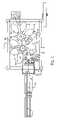
- FIG. 1is a schematic plan view of a cup making machine employing the bottom forming station components of the present invention
- FIG. 2is a perspective view of a cup made on the machine in FIG. 1 ;
- FIG. 3is a schematic representation of the bottom blank and the sidewall blank combined to form the cup of FIG. 2 ;
- FIG. 4is a sectional view showing the area at which the sidewall blank is joined to the bottom blank to form a bottom seal
- FIG. 5is a perspective view of a portion of the bottom finishing station showing the seam clamp and the clamp ring of the present invention
- FIG. 6is an elevational view of the seam clamp and the clamp ring of FIG. 5 ;
- FIG. 7is a sectional view taken on line 7 - 7 of FIG. 6 ;
- FIG. 7Ais a partial sectional view of a prior art seam clamp and clamp ring
- FIG. 8is a partial sectional view of the seam clamp and the clamp ring in relation to the sidewall blank, the bottom blank and the knurling wheel;
- FIG. 9is an exploded view of the seam clamp and the clamp ring.
- FIG. 10is an enlarged, sectional view of the seam clamp and the clamp ring used in making a cup with a left over right seam, the view being taken on line 10 - 10 - of FIG. 8 .
- Mandrel turret 22which cooperates with a transfer turret 24 and a rimming turret 26 .
- Mandrel turret 22includes a plurality of frustoconical mandrels 28 that are rotated in a stepwise or indexing manner between surrounding workstations. For example, a bottom blank may be applied to a given mandrel 28 at a bottom maker station 30 and then rotated to a bottom reformer station 32 .
- the mandrel 28is rotated into cooperation with the transfer turret 24 which receives sidewall blanks from a hopper 34 , and rotates the sidewall blank into cooperation with the cooperating mandrel 28 .
- the sidewall blankis then folded about the mandrel 28 over the bottom blank, heated and sealed along a seam.
- bottom blank and the sidewall blankare rotated to a bottom heat station 36 .
- mandrel turret 22indexes the subject mandrel 28 to a roller incurl station 38 where a portion of the sidewall blank, i.e. a sidewall blank flap, is bent over an outer lip of the bottom blank to form a recessed bottom in the cup.
- the cupis then moved to a bottom finishing station 40 where the sidewall blank flap and the bottom blank lip are pressed against the lower region of the sidewall blank to form a seal.
- the cupis transferred to rimming turret 26 and rotated to a lube station 42 and then to a rimming precurl station 44 where the upper lip of the sidewall is curled outwardly. From that station, the cup is indexed to a rimming finish curl station 46 which finishes the curled portion along the top of the cup to make an attractive edge. At this point, the cup may be moved to an optional lid groover station 48 and then to a cup blowoff station 50 for removal of the finished cup.
- Bottom finishing station 40can be sized and designed to make a variety of cups, and one example is illustrated in FIGS. 2-4 .
- An exemplary cup 52includes an upper region 54 having a curled rim 56 and a bottom region 58 .
- Cup 52is made from a sidewall blank 62 disposed generally transverse thereto.
- Bottom blank 62is typically bent or folded over in proximity to its outer edge to form a lip 64 .
- the sidewall blank 60is located with respect to bottom blank 62 so that a flap portion 66 extends beyond lip 64 .
- Flap portion 66is bent or folded around lip 64 so lip 64 may be squeezed between flap portion 66 and a lower portion 67 of sidewall blank 60 (see FIG. 4 ).
- a typical cup 52is made from paperboard blanks having a thermoplastic coating such as polypropylene.
- the thermoplastic materialpermits heating and sealing of adjacent components. For example, when sidewall blank 60 is wrapped around bottom blank 62 , the adjacent edges are heated and pressed together along a seam 68 .
- the cup making machine 20has the ability to create cups 52 with either a left over right seam 68 or a right over left seam 68 .
- lip 64 , flap portion 66 and lower region 67 of sidewall blank 60may be heated and pressed together at bottom finishing station 40 to form a strong, leak-proof bottom region 58 .
- a recessed area 70is created in the bottom of cup 52 on an opposite side of blank 62 from the main container region of cup 52 .
- Recessed area 70 in the bottom of the cuppermits insertion of a tool to press lip 64 and flap portion 66 towards the lower region 67 of sidewall blank 60 .
- a seam clamp assembly 72is positioned to engage and seal the seam 68 on the sidewall of the cup 52 .
- the sidewall blank 60is wrapped around the mandrel 28 with the edges of the sidewall blank 60 overlapping on top of the mandrel 28 .
- the seam clamp assembly 72is held in an open or up position by air which on release allows the assembly 72 to engage the seam 68 .
- the seam clamp assembly 72includes a seam clamp arm 74 which is mounted for reciprocal movement by structure as more fully disclosed in U.S. Pat. No. 5,752,907 issued May 19, 1998 which is herein incorporated by reference.
- a seam clamp 76is pivotally mounted about pivot pin 78 on clamp arm 74 .
- the seam clamp arm 74is free to pivot on pin 78 when a front edge 80 of the seam clamp 76 is moved into engagement with the tapered sidewall of mandrel 28 .
- a plunger portion 82 of the mandrel 28moves away from a nose cone 84 of the mandrel 28 as seen in FIG. 8 . This forces the lip 64 of bottom wall blank 62 into snug engagement with the bent lower portion of sidewall blank 60 at roller incurl station 38 to enable formation of a tight bottom seal at bottom forming station 40 .
- the bottom finishing station 40includes a clamp ring 86 .
- the clamp ring 86is selectively movable towards and away from the bottom of mandrel 28 by a carriage assembly such as more fully described in U.S. Pat. No. 5,569,143 issued Oct. 29, 1996, which is herein incorporated by reference.
- the clamp ring 86has an annular wall 88 that forms a circular recess for receiving a knurling wheel 90 .
- the knurling wheel 90is moved into and out of the recessed area 70 in the bottom of cups 52 , and then moved radially outwardly until a pre-heated flap portion 66 , lip 64 and the lower region 67 of cup 52 are squeezed tightly against wall 88 to help form the bottom seal.
- the lower end of the seam clamp 76is formed with a nose 92 which is received in a channel 94 cut into the clamp 86 , and is overlappingly engaged about an abutment 96 formed on the planar top surface 98 of the clamp ring 86 .
- the prior art relationship between the seam clamp and the clamp ringas shown in FIG.
- part of the seam clamp 76namely nose 92
- part of the clamp ring 86protrudes into the clamp ring 86
- part of the clamp ring 86namely, the abutment 96 rising above the planar top surface 98
- the nose 92when viewing the thickness thereof as seen in FIG. 10 , has a finger-like shape with tapered sidewalls 100 , 102 that are matingly received in the channel 94 .
- the channel 94is formed in an upper portion of the clamp ring 86 and has a flat bottom wall 104 and a pair of upwardly divergent sidewalls 106 , 108 that terminate at the planar top surface 98 of the clamp ring 86 .
- the abutment 96is integrally formed on the planar top surface 98 , and includes an upwardly angled sidewall 110 , a flat top wall 112 and a downwardly and outwardly sloping sidewall 114 that merges with channel sidewall 106 at the planar top surface 98 . About one half the length of top wall 112 and the entire length of sidewall 114 protrude into a curved face 116 of seam clamp 76 above nose 92 .
- the overall contour of the channel 94 and the abutment 96 on clamp ring 86forms a reverse S-shaped configuration or may be said to approximate a sinusoidal shape.
- the movable clamp ring 86carries a cam roller assembly 118 that is mounted on a bracket 120 held by fasteners 122 to a peripheral edge of the top planar surface 98 .
- the assembly 118has a cam roller 124 which rotates freely about a bolt 126 .
- the cam roller 124is engageable with an adjustable bolt 128 threaded into a member 130 on the lower portion of seam clamp 76 .
- the cam roller 124acts against the lower portion of seam clamp 76 which, in turn, acts against the sidewall seam 68 at the top of the cup bottom.
- mandrel turret 22is appropriately timed to interact with cup bottom finishing station 40 .
- the seam clamp 76is engaged against the overlapped edges of the sidewall blank 60 .
- the sidewall and bottom blanks 60 , 62have been heated and the bottom of sidewall blank 60 has been folded around the bottom blank lip 66 .
- the clamp ring 86is now moved towards the bottom of mandrel 28 until the bottom of mandrel 28 is received in the recess of the clamp ring 86 .
- the lower end of the seam clamp 76 and the clamp ring 86interface in matingly relationship as described above to provide a bridge to act against the side seam 68 at the top of the cup bottom.
- the knurling wheel 90is brought into the recess 70 in the cup bottom, and moved against the flap portion 66 , the lip 64 and the lower region 67 of cup 52 to complete the bottom seal.
- the present inventionthus provides for improving the interrelationship of the seam clamp 76 and the clamp ring 86 used in a bottom finishing station 40 to form the bottom seal of a cup in a manner which avoids channel leaks.
Landscapes
- Making Paper Articles (AREA)
- Casting Devices For Molds (AREA)
- Soil Working Implements (AREA)
- Catching Or Destruction (AREA)
Abstract
Description
Claims (10)
Priority Applications (5)
| Application Number | Priority Date | Filing Date | Title |
|---|---|---|---|
| US11/494,208US7686753B2 (en) | 2006-07-27 | 2006-07-27 | Bottom finishing station components for a cup making machine |
| DE602007006670TDE602007006670D1 (en) | 2006-07-27 | 2007-07-24 | COMPONENTS FOR THE LOWER PROCESSING STATION OF A MACHINE FOR THE PRODUCTION OF MUGS |
| AT07813255TATE468217T1 (en) | 2006-07-27 | 2007-07-24 | COMPONENTS FOR THE LOWER PROCESSING STATION OF A CUP PRODUCING MACHINE |
| PCT/US2007/074175WO2008014231A2 (en) | 2006-07-27 | 2007-07-24 | Bottom finishing station components for a cup making machine |
| EP07813255AEP2049326B1 (en) | 2006-07-27 | 2007-07-24 | Bottom finishing station components for a cup making machine |
Applications Claiming Priority (1)
| Application Number | Priority Date | Filing Date | Title |
|---|---|---|---|
| US11/494,208US7686753B2 (en) | 2006-07-27 | 2006-07-27 | Bottom finishing station components for a cup making machine |
Publications (2)
| Publication Number | Publication Date |
|---|---|
| US20080026924A1 US20080026924A1 (en) | 2008-01-31 |
| US7686753B2true US7686753B2 (en) | 2010-03-30 |
Family
ID=38962675
Family Applications (1)
| Application Number | Title | Priority Date | Filing Date |
|---|---|---|---|
| US11/494,208Active2027-07-24US7686753B2 (en) | 2006-07-27 | 2006-07-27 | Bottom finishing station components for a cup making machine |
Country Status (5)
| Country | Link |
|---|---|
| US (1) | US7686753B2 (en) |
| EP (1) | EP2049326B1 (en) |
| AT (1) | ATE468217T1 (en) |
| DE (1) | DE602007006670D1 (en) |
| WO (1) | WO2008014231A2 (en) |
Cited By (4)
| Publication number | Priority date | Publication date | Assignee | Title |
|---|---|---|---|---|
| US20180215497A1 (en)* | 2017-02-01 | 2018-08-02 | Uwe Messerschmid | Apparatus and method for producing containers from paper material or paper-like material, and container |
| US10398242B2 (en) | 2015-10-30 | 2019-09-03 | Paper Machinery Corporation | Overwrap container, method of and apparatus for producing same |
| US10835066B2 (en) | 2016-05-24 | 2020-11-17 | Paper Machinery Corporation | Process and apparatus for forming overwrap container using clamping and reforming |
| WO2024177516A1 (en)* | 2023-02-20 | 2024-08-29 | Punchbowl Packaging Limited | A packaging container, manufacturing process and manufacturing apparatus |
Families Citing this family (8)
| Publication number | Priority date | Publication date | Assignee | Title |
|---|---|---|---|---|
| TR200400866T4 (en) | 2001-01-30 | 2004-06-21 | Seda S.P.A | Cardboard beverage container and method for producing it |
| BRPI0601188B1 (en) | 2005-04-15 | 2018-06-26 | Seda S.P.A. | ISOLATED CONTAINER; METHOD OF MANUFACTURING THE SAME AND APPARATUS FOR MANUFACTURING |
| DE202005014177U1 (en) | 2005-09-08 | 2005-11-17 | Seda S.P.A., Arzano | Double-walled beaker comprises an inner wall formed by an inner beaker which is made of a fluid-tight plastic material, and is releasably inserted into an outer beaker forming the outer wall |
| PT1785370E (en) | 2005-11-11 | 2008-06-06 | Seda Spa | Insulated cup |
| EP1785265A1 (en) | 2005-11-14 | 2007-05-16 | SEDA S.p.A. | Device for producing a stacking projection on a container wall and container with same |
| DE202006018406U1 (en) | 2006-12-05 | 2008-04-10 | Seda S.P.A. | packaging |
| CN106714800B (en) | 2014-07-11 | 2021-09-03 | 吉利德科学公司 | TOLL-like receptor modulators for the treatment of HIV |
| CN113619191B (en)* | 2021-07-04 | 2023-06-13 | 浙江新德宝机械有限公司 | Paper container forming machine |
Citations (10)
| Publication number | Priority date | Publication date | Assignee | Title |
|---|---|---|---|---|
| US2942531A (en) | 1959-07-20 | 1960-06-28 | Paper Machinery Corp | Bottom expander for paper cups |
| US4349400A (en)* | 1977-05-10 | 1982-09-14 | Maryland Cup Corporation | Method for manufacturing two-piece containers from filled thermoplastic sheet material |
| US4409045A (en) | 1982-07-20 | 1983-10-11 | Maryland Cup Corporation | Method and apparatus for sealing the sidewall and bottom seam portions of two-piece containers during manufacture thereof |
| US4490130A (en) | 1981-08-10 | 1984-12-25 | Paper Machinery Corporation | Machine for forming seams of two-piece paper cups |
| US5337622A (en)* | 1988-10-11 | 1994-08-16 | Paper Machinery Corporation | Multi-mandrel programmable turret apparatus and method of effecting time modulation thereof |
| US5569143A (en) | 1994-09-15 | 1996-10-29 | Paper Machinery Corporation | Cup bottom finishing station for a cup making machine |
| US5584789A (en)* | 1994-09-06 | 1996-12-17 | Sealright Co., Inc. | Method and apparatus for forming non-round containers |
| US5752907A (en) | 1995-08-15 | 1998-05-19 | Paper Machinery Corporation | Cup making machine |
| US6558305B1 (en) | 1998-05-29 | 2003-05-06 | Upm-Kymmene Corporation | Apparatus that clamps an end member to a casing |
| US20060095151A1 (en) | 2004-11-02 | 2006-05-04 | Mannlein Dean J | Computer controlled cup forming machine |
- 2006
- 2006-07-27USUS11/494,208patent/US7686753B2/enactiveActive
- 2007
- 2007-07-24WOPCT/US2007/074175patent/WO2008014231A2/enactiveApplication Filing
- 2007-07-24ATAT07813255Tpatent/ATE468217T1/ennot_activeIP Right Cessation
- 2007-07-24EPEP07813255Apatent/EP2049326B1/ennot_activeCeased
- 2007-07-24DEDE602007006670Tpatent/DE602007006670D1/enactiveActive
Patent Citations (10)
| Publication number | Priority date | Publication date | Assignee | Title |
|---|---|---|---|---|
| US2942531A (en) | 1959-07-20 | 1960-06-28 | Paper Machinery Corp | Bottom expander for paper cups |
| US4349400A (en)* | 1977-05-10 | 1982-09-14 | Maryland Cup Corporation | Method for manufacturing two-piece containers from filled thermoplastic sheet material |
| US4490130A (en) | 1981-08-10 | 1984-12-25 | Paper Machinery Corporation | Machine for forming seams of two-piece paper cups |
| US4409045A (en) | 1982-07-20 | 1983-10-11 | Maryland Cup Corporation | Method and apparatus for sealing the sidewall and bottom seam portions of two-piece containers during manufacture thereof |
| US5337622A (en)* | 1988-10-11 | 1994-08-16 | Paper Machinery Corporation | Multi-mandrel programmable turret apparatus and method of effecting time modulation thereof |
| US5584789A (en)* | 1994-09-06 | 1996-12-17 | Sealright Co., Inc. | Method and apparatus for forming non-round containers |
| US5569143A (en) | 1994-09-15 | 1996-10-29 | Paper Machinery Corporation | Cup bottom finishing station for a cup making machine |
| US5752907A (en) | 1995-08-15 | 1998-05-19 | Paper Machinery Corporation | Cup making machine |
| US6558305B1 (en) | 1998-05-29 | 2003-05-06 | Upm-Kymmene Corporation | Apparatus that clamps an end member to a casing |
| US20060095151A1 (en) | 2004-11-02 | 2006-05-04 | Mannlein Dean J | Computer controlled cup forming machine |
Non-Patent Citations (1)
| Title |
|---|
| International Search Report dated Jun. 2, 2008. |
Cited By (5)
| Publication number | Priority date | Publication date | Assignee | Title |
|---|---|---|---|---|
| US10398242B2 (en) | 2015-10-30 | 2019-09-03 | Paper Machinery Corporation | Overwrap container, method of and apparatus for producing same |
| US10835066B2 (en) | 2016-05-24 | 2020-11-17 | Paper Machinery Corporation | Process and apparatus for forming overwrap container using clamping and reforming |
| US20180215497A1 (en)* | 2017-02-01 | 2018-08-02 | Uwe Messerschmid | Apparatus and method for producing containers from paper material or paper-like material, and container |
| US11104472B2 (en)* | 2017-02-01 | 2021-08-31 | Michael Hörauf Maschinenfabrik Gmbh Und Co. Kg | Apparatus and method for producing containers from paper material or paper-like material, and container |
| WO2024177516A1 (en)* | 2023-02-20 | 2024-08-29 | Punchbowl Packaging Limited | A packaging container, manufacturing process and manufacturing apparatus |
Also Published As
| Publication number | Publication date |
|---|---|
| DE602007006670D1 (en) | 2010-07-01 |
| WO2008014231A3 (en) | 2008-03-27 |
| ATE468217T1 (en) | 2010-06-15 |
| US20080026924A1 (en) | 2008-01-31 |
| EP2049326B1 (en) | 2010-05-19 |
| EP2049326A2 (en) | 2009-04-22 |
| WO2008014231A2 (en) | 2008-01-31 |
Similar Documents
| Publication | Publication Date | Title |
|---|---|---|
| US7686753B2 (en) | Bottom finishing station components for a cup making machine | |
| US7311243B1 (en) | Two piece paper cup and sidewall blank therefor | |
| US20120043374A1 (en) | Sidewall blank for substantially eliminating twist in deep bottom containers | |
| US7584639B2 (en) | Method and device for the production of a can body, and can body | |
| US10398242B2 (en) | Overwrap container, method of and apparatus for producing same | |
| US10835066B2 (en) | Process and apparatus for forming overwrap container using clamping and reforming | |
| JP2019513649A (en) | Method and apparatus for forming a package body which is open at one end from a package sleeve which is open at both ends | |
| US10035692B2 (en) | Funnel and receptacle defined by the funnel | |
| EP1554111B1 (en) | Methode and machine for forming containers, in particular containers for food products | |
| CN105151451A (en) | Method for producing cup | |
| EP1091846B1 (en) | Apparatus that clamps an end member to a casing | |
| US6790168B1 (en) | Automated system and method for forming two stage cup | |
| US3157339A (en) | Paper cup with caulked bottom and method of making | |
| AU2001285355B2 (en) | Method and apparatus for constructing an end portion of a food sauce dispensing cartridge | |
| US20140318082A1 (en) | Method and device for production of can with fold lines | |
| US1979827A (en) | Method and apparatus for manufacturing containers | |
| US1896076A (en) | Container and manufacture of same | |
| US2584542A (en) | Apparatus for making tubular paper containers | |
| US2620942A (en) | Can body and longitudinal seam therefor | |
| US2863367A (en) | Cone cup machine | |
| JP2015013406A (en) | Wing metal mold and cup molding device using the same | |
| US1723304A (en) | Method of sealing cans |
Legal Events
| Date | Code | Title | Description |
|---|---|---|---|
| AS | Assignment | Owner name:PAPER MACHINERY CORPORATION, WISCONSIN Free format text:ASSIGNMENT OF ASSIGNORS INTEREST;ASSIGNOR:KONZAL, MR DARYL R.;REEL/FRAME:018188/0120 Effective date:20060725 Owner name:PAPER MACHINERY CORPORATION,WISCONSIN Free format text:ASSIGNMENT OF ASSIGNORS INTEREST;ASSIGNOR:KONZAL, MR DARYL R.;REEL/FRAME:018188/0120 Effective date:20060725 | |
| STCF | Information on status: patent grant | Free format text:PATENTED CASE | |
| FPAY | Fee payment | Year of fee payment:4 | |
| AS | Assignment | Owner name:JPMORGAN CHASE BANK, N.A., WISCONSIN Free format text:SECURITY INTEREST;ASSIGNOR:PAPER MACHINERY CORPORATION;REEL/FRAME:038552/0849 Effective date:20160429 | |
| MAFP | Maintenance fee payment | Free format text:PAYMENT OF MAINTENANCE FEE, 8TH YR, SMALL ENTITY (ORIGINAL EVENT CODE: M2552) Year of fee payment:8 | |
| MAFP | Maintenance fee payment | Free format text:PAYMENT OF MAINTENANCE FEE, 12TH YR, SMALL ENTITY (ORIGINAL EVENT CODE: M2553); ENTITY STATUS OF PATENT OWNER: SMALL ENTITY Year of fee payment:12 |