US7685292B1 - Techniques for establishment and use of a point-to-point tunnel between source and target devices - Google Patents
Techniques for establishment and use of a point-to-point tunnel between source and target devicesDownload PDFInfo
- Publication number
- US7685292B1 US7685292B1US11/399,593US39959306AUS7685292B1US 7685292 B1US7685292 B1US 7685292B1US 39959306 AUS39959306 AUS 39959306AUS 7685292 B1US7685292 B1US 7685292B1
- Authority
- US
- United States
- Prior art keywords
- tunnel
- connection
- client
- server
- request
- Prior art date
- Legal status (The legal status is an assumption and is not a legal conclusion. Google has not performed a legal analysis and makes no representation as to the accuracy of the status listed.)
- Active, expires
Links
Images


Classifications
- H—ELECTRICITY
- H04—ELECTRIC COMMUNICATION TECHNIQUE
- H04L—TRANSMISSION OF DIGITAL INFORMATION, e.g. TELEGRAPHIC COMMUNICATION
- H04L12/00—Data switching networks
- H04L12/28—Data switching networks characterised by path configuration, e.g. LAN [Local Area Networks] or WAN [Wide Area Networks]
- H04L12/46—Interconnection of networks
- H04L12/4633—Interconnection of networks using encapsulation techniques, e.g. tunneling
- H—ELECTRICITY
- H04—ELECTRIC COMMUNICATION TECHNIQUE
- H04L—TRANSMISSION OF DIGITAL INFORMATION, e.g. TELEGRAPHIC COMMUNICATION
- H04L63/00—Network architectures or network communication protocols for network security
- H04L63/02—Network architectures or network communication protocols for network security for separating internal from external traffic, e.g. firewalls
- H04L63/0272—Virtual private networks
- H—ELECTRICITY
- H04—ELECTRIC COMMUNICATION TECHNIQUE
- H04L—TRANSMISSION OF DIGITAL INFORMATION, e.g. TELEGRAPHIC COMMUNICATION
- H04L63/00—Network architectures or network communication protocols for network security
- H04L63/04—Network architectures or network communication protocols for network security for providing a confidential data exchange among entities communicating through data packet networks
- H04L63/0428—Network architectures or network communication protocols for network security for providing a confidential data exchange among entities communicating through data packet networks wherein the data content is protected, e.g. by encrypting or encapsulating the payload
- H04L63/0471—Network architectures or network communication protocols for network security for providing a confidential data exchange among entities communicating through data packet networks wherein the data content is protected, e.g. by encrypting or encapsulating the payload applying encryption by an intermediary, e.g. receiving clear information at the intermediary and encrypting the received information at the intermediary before forwarding
- H—ELECTRICITY
- H04—ELECTRIC COMMUNICATION TECHNIQUE
- H04L—TRANSMISSION OF DIGITAL INFORMATION, e.g. TELEGRAPHIC COMMUNICATION
- H04L63/00—Network architectures or network communication protocols for network security
- H04L63/16—Implementing security features at a particular protocol layer
- H04L63/168—Implementing security features at a particular protocol layer above the transport layer
Definitions
- This applicationgenerally relates to computer connectivity, and more particularly to secure communication connections.
- a user on a source devicemay want to connect to a remote computer or other remote device.
- the remote devicemay not be visible to the source device such that the user may not be able to establish a connection to the remote device to transmit messages.
- Existing solutions in order to establish a secure connection between two devicesmay include using a persistent secure tunnel, or an on-demand secure tunnel between either the two networks or two devices.
- both of the foregoingmay require that at least the remote target device, or a device with visibility to the target device, be visible to the source device from which the user wishes to establish the connection. In some instances, it may not be possible, such as due to security policies, to have the target device be visible to the remote source device
- a method for establishing a secure connection between a source device and a target devicecomprising: providing a first connection between a tunnel client and a tunnel server, a second connection between said tunnel server and said source device, and a third connection between said tunnel client and said target device; receiving a request over said second connection at said tunnel server from the source device to send data to the target device; sending a first message from the tunnel client to the tunnel server over said first connection; sending said request in a return message over said first connection to said tunnel client; and sending said request to said target device from said tunnel client over said third connection.
- the source devicemay have visibility to the tunnel server, the tunnel client may visibility to the target device, and the tunnel client may have visibility to the tunnel server.
- the source devicemay not have visibility to the target device.
- the tunnel servermay be included in a perimeter device of a source network which communicates with said source device.
- the methodmay also include: receiving, at said tunnel server over said second connection, a request from said source device to establish a tunnel; and transmitting said request over a fourth connection between said tunnel server and said tunnel client.
- the first connectionmay be continually re-established at a predetermined time interval.
- the first connection and a fourth connectionmay be used to transmit messages between said tunnel server and said tunnel client, said first connection being used to transmit messages and responses to initiate and terminate a tunnel between said source device and said target device, said fourth connection being used to transmit other messages.
- the fourth connectionmay be characterized as having a higher priority link that said first connection.
- the first connection and said fourth connectionmay be each continually re-established in accordance with different establishment time intervals.
- the first connectionmay have an expiration time interval indicating how long said first connection remains established.
- the first connectionmay remain established until occurrence of said expiration time interval elapsing, or said tunnel server receives a message to transmit over said first connection.
- Each of the first connection and the fourth connectionmay have different message queues.
- the tunnel servermay service a plurality of tunnel clients.
- the tunnel clientmay connect to a plurality of tunnel servers.
- the tunnel servermay be included on an interior device of a source network. At least one of said tunnel client and said tunnel server may permit access from a source network including said source device to a target network including said target device in accordance with access control privileges.
- the access control privileges of said tunnel clientmay indicate what devices in the target network are accessible to a particular user of said source network, and wherein said access control privileges of said tunnel server may specify privileges of users of the source network to access devices in the target network.
- the source devicemay be included in a source network and said target device may be included in a target network, said source network being a service provider network to perform monitoring of one or more objects in said target network, at least one of said objects being at a location of said tunnel client.
- the service provider networkmay establish communications with said target network by sending said request over said second connection.
- a method for communicating between a source device and a target devicecomprising: receiving, at a tunnel server, a request from a source device to initiate a tunnel to said target device; transmitting said request from said tunnel server to a tunnel client over a first connection, said request being included in a return message to said tunnel client in response to another request from said tunnel client previously received at said tunnel server; and wherein said tunnel server receives incoming messages from said tunnel client and said tunnel server transmits an outgoing request from said source device to said target device by including said outgoing request in a return message to said tunnel client in response to one of said incoming messages, and wherein said tunnel client communicates said outgoing request to said target device over a second connection, and said source device and said tunnel server communication over a third connection.
- a computer-readable mediumincluding code thereon for establishing a secure connection between a source device and a target device
- the computer-readable mediumcomprising code that: provides a first connection between a tunnel client and a tunnel server, a second connection between said tunnel server and said source device, and a third connection between said tunnel client and said target device; receives a request over said second connection at said tunnel server from the source device to send data to the target device; sends a first message from the tunnel client to the tunnel server over said first connection; sends said request in a return message over said first connection to said tunnel client; and sends said request to said target device from said tunnel client over said third connection.
- FIG. 1is an example of an embodiment of a system that may utilize the techniques described herein;
- FIG. 2is a flowchart of processing steps that may be performed in an embodiment of the system of FIG. 1 as part of setup processing to establish a reverse point-to-point tunnel between the source device and one or more target devices;
- FIG. 3is a flowchart of processing steps that may be performed in an embodiment connection with the source and target networks of FIG. 1 ;
- FIG. 4is a flowchart of more detailed processing steps of FIG. 3 that may be performed in connection with the reverse point-to-point tunneling technique described herein;
- FIG. 5is an illustration of the flow of data that may be performed in an embodiment in connection with a reverse point-to-point tunnel using the techniques described herein;
- FIG. 5Ais an example illustrating use of establishment time intervals and expiration time intervals
- FIG. 6is a flowchart of the processing steps of FIG. 4 with additional detail in connection with the use of connections C 1 -C 4 illustrated in FIG. 5 ;
- FIGS. 7 and 8are further examples of embodiments of different configurations that may be used in connection with the techniques herein;
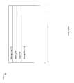
- FIG. 9is an example of an embodiment of a message format that may be used in connection with the techniques described herein.
- FIG. 10is an example of an embodiment of components that may be included in a computer system used in connection with the techniques described herein.
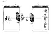
- the example 100includes two networks, the source network 110 and the target network 120 .
- the source network 110is the network from which the remote access may be initiated.
- the target network 120is the network to which a connection may be made remotely from the source network.
- the example 100also includes a source device 112 , a tunnel server 114 , a target device 122 and a tunnel client 124 .
- the source device 112is the device on the source network 110 from which the remote access may be initiated.
- the target device 122is the device to which remote access may be obtained. Note that the source device 112 can be any device that has visiblity to the Tunnel Server.
- the target device 122can be any device to which the Tunnel Client has visibility. Similarly, the Tunnel Client has visibility to the Tunnel Server.
- the foregoing visibility characteristicsare present in an arrangement in which the location of the source device is within the source network, the Tunnel Server is included on a perimeter device, and the target device and Tunnel Client are included in the target network.
- the techniques described hereinmay be used with other arrangements of the components in accordance with the same visibility characteristics.
- an embodimentmay include one or more of the devices, Tunnel Server and/or Tunnel client in different arrangements than as described with reference to FIG. 1 .
- the Tunnel Clientmay be included, for example, in a different network than the target device.
- the Tunnel Server, Tunnel Client, source device and target devicemay all be included within the same network.
- tunnel Server 114 and the Tunnel Client 124are components that may be used in connection with establishing, maintaining, and utilizing a reverse point-to-point tunnel as part of a secure connection between the source and target networks. Both the Tunnel Server 114 and Tunnel Client 124 are described in more detail in following paragraphs.
- the target networkis not required to be visible to the source network. In other words, there may not exist a route for network traffic to pass from a device on the source network 110 to a device on the target network 120 . However, the Tunnel Server 114 on the source network 110 is visible to at least the device on which the Tunnel Client 124 is installed on the target network 120 .
- the Tunnel Serveris installed on the source network such that the Tunnel Server is visible, for example, across the WAN link (e.g. Internet) from the target network as illustrated in FIG. 1 .
- the connectionmay be any one or more types of communication links known to those of ordinary skill in the art such as for, example, a modem connection, a T3 pipe, and the like.
- an accountis setup on the Tunnel Server for the specific target network 120 .
- the accountmay include, for example, any form of a two-factor authentication (e.g., an identifier and a password). Other authentication information and techniques known in the art may also be used.
- the Tunnel Clientis installed on a device on the target network that has visibility to one or more devices to which the source network wants remote access. With reference to FIG. 1 , the Tunnel Client is installed on the device 124 of the target network 120 . As part of the installation processing of step 206 , the Tunnel Client may be provided with the location of the Tunnel Server (e.g. an IP address of the Tunnel Server), and the authentication information provided with the account setup for this target network from step 204 .
- the Tunnel Servere.g. an IP address of the Tunnel Server
- a tunnelcan be requested on demand from the source network to any visible device on the target network.
- a requestis made to establish a tunnel to a specific device in the target network. This request may be made, for example, by a user of the source device or an application program residing and executing on the source device.
- This request for a tunnelis received by the Tunnel Server and communicated, at step 304 , to the Tunnel Client using a “heartbeat” connection and other connections as described in more detail in following paragraphs.
- Processing of step 304may include one or more sets of messages exchanged between the Tunnel Server and Tunnel Client.
- a requestmay be made to terminate the tunnel. Such a termination request may be made, for example, from the user or application on the source device 112 of the source network 112 .
- the “heartbeat” connectionwhich facilitates communications between the source and target networks using data request or messages initiated by the Tunnel Client of the target network.
- the “heartbeat” connectionmay be characterized a recurring connection that is continually established and torn down after a message exchange during the lifetime of the Tunnel Client. It can be characterized as a “heartbeat” connection, because even if there is no data to be transferred, the connection is closed at a predefined expiration interval. This establishes liveliness of the connection to within that expiration interval.
- the Tunnel Clientmay initiate an outbound connection to the Tunnel Server.
- This connectionreferred to herein as the “heartbeat” connection, may be characterized as an intermittent connection that is continually established and torn down for the lifetime of the Tunnel Client.
- the Tunnel Client 124may continually send a message at predetermined time intervals to the Tunnel Server 114 . For each sent message, a return message is transmitted from the Tunnel Server 114 to the Tunnel Client 124 . It is through the use of this heartbeat connection that data is transmitted between the source network 110 and the target network 120 .
- the Tunnel Clientmay send a message to the Tunnel Server providing the authorization information, such as the two-factor authentication information as described elsewhere herein, to allow for authentication of the Tunnel Client to the Tunnel Server.
- the Tunnel Clientmay also transmit any results to the Tunnel Server to previous requests, or otherwise resulting from previous requests. This data may be received at the Tunnel Server for further processing and/or dispatching by the Tunnel Server on the source network as described in more detail in following paragraphs.
- the Tunnel Servermay include an outgoing queue of requests, such as requests from the source device 112 , or other data to be transmitted to the Tunnel Client. Any pending requests in the Tunnel Server's outgoing queue may be retrieved and transmitted back to the Tunnel Client. If there are multiple requests in the outgoing queue, these requests may be packaged in a single message sent to the Tunnel Client. It should be noted that since the Tunnel Client may not be visible to the Tunnel Server in an embodiment as described herein, the Tunnel Server may rely on the Tunnel Client to “pull” the requests instead of the Tunnel Server “pushing” the requests.
- Traffic flowing over the heartbeat connectionmay be encrypted for security and compressed to reduce bandwidth utilization.
- the heartbeat connectionmay not necessarily be a persistent connection and can be established and torn down as needed.
- a requestis made from the source device to establish a tunnel.
- the requestmay be, for example, from a source device to establish a tunnel to a specific device on the target network for a specific protocol (e.g. connect to device A using telnet).
- the requestis received by the Tunnel Client though the Tunnel Client's link to the Tunnel Server.
- This requestmay be placed in the outgoing queue of the Tunnel Server and is transmitted to the Tunnel Client in the next return message through the heartbeat connection.
- the Tunnel Clientreceives the message and establishes a connection to the specified target device.
- the Tunnel Clientnotifies the Tunnel Server via a return response message regarding successful creation of the connection to the target device.
- the Tunnel Serverthen provides an end-point (e.g., TCP port) for use by the source device to establish a connection through the tunnel to the target device.
- the source deviceconnects to the tunnel server using the provided end-point.
- the tunnel server and tunnel clientfacilitate communication of data between the source and target devices using the heartbeat and other connections.
- step 414may include one or more messages and associated responses between the two networks until a request is made to terminate the existing tunnel.
- a requestis made from the source device to tunnel server to terminate the tunnel.
- the terminate tunnel requestis received by the Tunnel Client through the Tunnel Client's link to the Tunnel Server, such as using the heartbeat connection and other connections.
- a response messageis sent from the Tunnel Client to the Tunnel Server reporting on the status of the tunnel termination operation.
- an embodimentmay also provide for termination of the tunnel in other ways. For example, at any point during the communication, it is possible for an application on the target device to terminate the connection to the Tunnel Client. If this occurs, step 420 may be executed directly after step 414 .
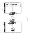
- FIG. 5shown is an illustration 250 of the flow of data that may be performed in an embodiment in connection with a reverse point-to-point tunnel. Included in this example are four connections, C 1 -C 4 , over which various messages, or requests, may be transmitted between the source and target networks. The particular messages that may be exchanged in an embodiment are described in more detail elsewhere herein. What will now be described is the general flow of data over these connections with reference to the previously described processing steps of FIG. 4 .
- Connection C 1corresponds to the heartbeat connection used for bidirectional communications between the Tunnel Client and Tunnel Server in which a first heartbeat message is sent from the Tunnel Client to the Tunnel Server. The return second heartbeat message is sent from the Tunnel Server to the Tunnel Client. In this second heartbeat message, the request to establish a tunnel, as well as other message types, may be transmitted.
- one or more connections or linksmay correspond to the heartbeat connection as described herein to facilitate communications between the source and target networks.
- two connections, C 1 and C 4may be used as the heartbeat connections. The use of connection C 4 may allow for the reduction in latency in the data transmissions between the source and target devices, and may be used for the transfer of data between these two devices.
- Connection C 1as well as C 4 described below, have been illustrated in FIG. 5 with dotted lines to denote that these connections are not necessarily a persistent connections and can be established and terminated as needed.
- Connection C 4may be characterized as a higher priority link than connection C 1 that may be included in an embodiment.
- Connection C 4may be used to transmit particular types of messages between the Tunnel Client and Tunnel Server.
- Connection C 1may be used to transmit the remaining types of messages that may occur between the Tunnel Server and Tunnel Client not transmitted over connection C 4 .
- connection C 4may use additional resources beyond those used for connection C 1 .
- Connection C 1may be used for transmitting the messages and responses to initiate and terminate a tunnel.
- Connection C 4may be used for transmitting remaining message types including data sent to/from the source and target devices.
- Connection C 4may parallel functionality of connection C 1 with the addition of a reduced interval (e.g., the establishment interval as described elsewhere herein) between the establishment and teardown of connections. Both C 1 and C 4 may use compression. Thus, once a tunnel has been established using connection C 1 , connection C 4 may be used to transmit data between source and target devices until a terminate tunnel message is sent by the source device. The use of the additional connection C 4 allows for data to be transmitted between Tunnel Server and Tunnel Client efficiently while also minimizing traffic using compression. The foregoing use of both the C 1 and C 4 connections may be preferred, for example, if a tunnel is used in transferring data in accordance with both lightweight and heavyweight protocols (e.g., telnet vs. a graphical remote access protocol such as RDP) over both low and high throughput links (e.g., 56K modem vs. a T3 connection).
- lightweight and heavyweight protocolse.g., telnet vs. a graphical remote access protocol such as RDP
- Connection C 2denotes the bidirectional connection between the Tunnel Client and the Target Device.
- Connection C 3denotes the bidirectional connection between the source device and the Tunnel Server.
- the Tunnel Servermay include two outgoing queues.
- a first queuemay be used to queue outgoing messages over connection C 1 .
- a second queuemay be used to queue outgoing messages over connection C 4 .
- the Tunnel Servermay classify the message type and accordingly place the message in the appropriate outgoing queue. If the message is a request for establishing or terminating a tunnel, the Tunnel Server may place the message in the outgoing queue for connection C 1 if the connection C 1 is not yet established.
- the Tunnel Serveruses connection C 4 and C 4 's associated outgoing queue as appropriate.
- a single prioritized message queuemay be used including outgoing requests for both C 1 and C 4 .
- the messages in the single queuemay be prioritized in accordance with any one or more criteria such as message type, age of message, and the like.
- the Tunnel Clientmay also include two outgoing queues, one for the responses to requests made by the Tunnel Server over C 1 , and another for the requests and response for delivery over C 4 .
- the Tunnel Client's outgoing queue for C 4can be used to optimize the performance of the connections.
- connection C 4can be established based on its establishment interval or timeout, or in response to items being included in the outgoing transmission queue. This ensures timely delivery of requests to the Tunnel Server.
- any other data structurecan be used for the interim caching of requests and responses.
- Connections C 1 and C 4may be established and torn down at predetermined time intervals (the establishment timeout or interval).
- a first time intervalis used for C 1 which may be different than the time interval used for C 4 .
- the particular time intervals selectedmay vary in accordance with the message traffic and other particulars in an embodiment.
- the connection C 1may be established by the Tunnel Client to the Tunnel Server each first time interval. Connection C 1 may remain established for a time period, such as 30 seconds, or until the Tunnel Server receives an outgoing request, whichever occurs first.
- This time periodindicating the amount of time a connection remains once established, may be referred to as an expiration timeout and can be used to minimize the resource utilization on the Tunnel Client or Tunnel Server by reducing the number of overall times in which a connection may be established and re-established.
- the Tunnel ServerUpon the occurrence of either the time period expiring or receipt of an outgoing request for C 1 , the Tunnel Server transmits a response heartbeat message over C 1 to the Tunnel Client. If there is a pending message to be sent to the Tunnel Client, the response message includes the outgoing message data.
- the connection C 4may be established by the Tunnel Client in a similar manner using the same expiration timeout, but a different establishment timeout. In one embodiment, the establishment interval for C 4 may be smaller than the establishment interval associated with C 1 .
- connection C 4may also be established by the Tunnel Client in an event-driven manner when there is data to be sent to the Tunnel Server as soon as items are added into its queues. Once a connection C 4 is established, it may remain until expiration of the specified expiration timeout, or until an outgoing message is received by the Tunnel Server for transmission to the Tunnel Client. Upon the occurrence of either the expiration time period expiring or receipt of an outgoing request over connection C 4 , the Tunnel Server transmits a response heartbeat message over C 4 to the Tunnel Client. If there is a pending message to be sent to the Tunnel Client, the response message includes the outgoing message data.
- the associated connectionsmay remain for a specified expiration timeout that may vary with each connection.
- the expiration timeoutis the amount of time that the link or connection remains established to wait for the possible arrival of outgoing requests from the Tunnel Server.
- each of 452 a , 452 b , 452 c , and 452 dmay represent an establishment time interval elapsing at a point in time.
- Each of 456 a , 456 b , 456 c , and 456 dmay represent an absolute amount of time equal to the expiration time interval.
- Each expiration time interval( 456 a , 456 b , 456 c , and 456 d ) may be measured with respect to an occurrence of an establishment time interval.
- Each of 454 a , 454 b , 454 c and 454 dmay represent the resultant time after an expiration time interval has elapsed with respect to an establishment time interval occurrence.
- a connectionsuch as C 1
- the connection C 1may remain established for a time period indicated by the expiration time interval or timeout (e.g., 456 a , 456 b , 456 c , and 456 d ), or until the Tunnel Server receives an outgoing request, whichever occurs first.
- the connection C 1 at each establishment time intervalwill remain established no longer than the expiration time interval.
- an embodimentmay include one or more Tunnel Servers in communication with one or more Tunnel Clients.
- a Tunnel Servercan serve one or more Tunnel Clients and a Tunnel Client can connect to one or more Tunnel Servers.
- a single Tunnel Servercan allow connections from one or more Tunnel Clients residing on the same or different target networks.
- a single Tunnel Clientcan support multiple tunnels to the same or different device. In the event of more than one tunnel being established between source/target devices, the Tunnel Client utilizes the same connections C 1 and C 4 , thereby minimizing resource utilization on the Tunnel Client and Tunnel Server.
- a Tunnel Clientcan also be configured to connect to multiple Tunnel Servers, for supporting either remote access from multiple source locations, redundancy or failover.
- the Tunnel Servers that a single Tunnel Client connect tocan be on the same or different source networks.
- a requestis made from the source device to establish a tunnel and is placed in the Tunnel Server's outgoing request queue.
- the establish tunnel requestis retrieved at step 506 from the outgoing request queue the next time a C 1 “heartbeat” connection is established.
- the requestmay be transmitted as a return heartbeat message in which data is pulled from the tunnel server by the tunnel client.
- the Tunnel Clienthandles the request by establishing a connection C 2 between the Tunnel Client and the specified device, using the specified protocol.
- the Tunnel Clientthen notifies the Tunnel Server of the successful creation of the connection C 2 to the target device using connection C 1 .
- the Tunnel Serverthen provisions an available end-point for use by the source device to establish the connection thru the tunnel to the target device (e.g. TCP port 24001).
- This end-pointrepresents a virtual connection to the target device.
- the end-pointsuch as a port, is communicated back to the person or software that made the request at step 502 to establish the tunnel.
- the person or software on the source devicethen uses any third-party technology capable of communicating using the specified protocol (e.g. telnet) to establish connection C 3 between the source device and the Tunnel Server.
- the specified protocole.g. telnet
- the Tunnel Server and Tunnel Clientcommunicate using heartbeat connection C 4 until a request is made, at step 518 , to terminate the tunnel.
- the request to terminate the tunnelis made at step 518 over connection C 3 and is received by the Tunnel Server.
- the Tunnel Serverthen transmits the request to terminate the tunnel over connection C 1 .
- the Tunnel Serverterminates connection C 3 and then sends a terminate tunnel request to the Tunnel Client through C 1 connection.
- the request to terminate the tunnelis received by the Tunnel Client.
- the Tunnel Clientterminates the C 2 connection and then disconnects the C 4 connection at step 526 .
- the Tunnel Clientsends a response over connection C 1 to the Tunnel Server.
- step 516the application on the target device can terminate the connection C 2 based on the protocol state. If C 2 is terminated due to this or any other connectivity issue, step 524 directly executes after step 516 , skipping all intervening steps.
- the request to terminate the tunnelmay be made by a user or software of the source device by issuing a terminate tunnel request.
- a termination requestmay be made by also closing an application making use of the tunnel. If the application has been terminated, a network level disconnect may be received by the Tunnel Server via the C 3 connection. If the tunnel disconnect has been requested directly, a disconnect request is received by the Tunnel Server external to the standard connections. In connection with the response sent at step 528 , if the disconnect request was made directly to the Tunnel Server via an external channel, the successful termination status is returned to the caller.
- a status or response messagemay be returned in connection with one or more operations as described herein even though not explicitly described herein.
- a status message indicating success or failuremay be returned to the Tunnel Server.
- Each of the status messagesmay be returned using the particular heartbeat connection (e.g., C 1 or higher priority link C 4 ) in accordance with the particular request message type.
- connections C 1 and C 4may be encrypted for security. Additionally, connection C 4 may perform transmissions using data compression to reduce bandwidth utilization.
- processingmay be performed in connection with transmission of data to/from the source device and the Tunnel Server, and between the Tunnel Client and the target device.
- an embodimentmay utilize one or more criteria in connection with the techniques described herein.
- One embodimentmay utilize as criteria minimization of the following four factors:
- an embodimentmay use the C 4 higher priority link in addition to the C 1 link as described herein as the two “heartbeat” connections, each connection used for transmission of different message types as described elsewhere herein.
- C 4allows for efficient data transmissions, seeks to minimize the amount of traffic through compression, and allows both the Tunnel Client and Tunnel Server to only utilize the additional resources needed to support the tunnel once a tunnel has been established.
- the reduced establishment timeout for C 4also serves to reduce latency, and the existence of an expiration timeout serves to reduce resource utilization on both the Tunnel Server and Tunnel Client.
- the tunnelcan be used in an embodiment to transfer both light and heavyweight protocols (e.g. telnet vs. a graphical remote access protocol such as RDP) over both low and high-throughput links (e.g. 56K modem vs. T3).
- light and heavyweight protocolse.g. telnet vs. a graphical remote access protocol such as RDP
- RDPgraphical remote access protocol
- low and high-throughput linkse.g. 56K modem vs. T3
- connection C 1 or C 4may be used to transmit the request between the Tunnel Server and Tunnel Client. Additionally, the other connections C 2 and C 3 are also used as described herein in connection with forwarding data between the source and target devices.
- an embodimentmay also include a fifth type of request originating from the target device to terminate the tunnel.
- the messageis sent from the target device to the source device.
- a fifth type of requestis generated, with reference to the connections illustrated in FIG. 5 , the C 2 connection is terminated.
- a message including the fifth type of request to terminate the tunnelmay be sent over connection C 4 from the Tunnel Client to the Tunnel Server with the remaining data received from the target device.
- the Tunnel Servermay then terminate the C 3 connection.
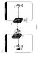
- FIGS. 7 and 8are further examples of embodiments of different configurations that may be used in connection with the techniques herein.
- the techniques described hereinmay be used in connection with providing on-demand services such as, for example, remote access, monitioring, configuration management, or the delivery of a service such as through an embedded device such as a firewall device 704 .
- the Tunnel Clientmay reside on the perimeter firewall device 702 of the target network.
- the tunnel client in this embodiment of FIG. 9may be implemented using, for example, software and/or firmware on the perimeter firewall device 702 .
- a user on a source device 704may remotely access a target device 706 visible only to the interior link of the firewall (e.g., the source device does not have visibility to the target device).
- an embodimentmay use the techniques described herein in connection with providing on-demand services such as, for example, for remote access, monitoring, configuration management, or the delivery of a service through an embedded device such as a keyboard-video-mouse device (KVM) 802 .
- KVMkeyboard-video-mouse device
- the example 800shows the Tunnel Client residing on a network-enabled KVM device 802 that is connected to one or more target systems that may be include in the same, or different networks.
- the Tunnel Client included in 802may be implemented, for example, using software and/or firmware on the KVM device 802 .
- a user on a source device 804may remotely access and control, both in-band and out of band, a target device 806 visible only from the KVM (e.g., the source device does not have visibility to the target device).
- the example 550 message formatmay be used in connection with sending requests and responses in connection with the techniques described herein.
- the example 550includes a message type 552 , a source 554 , a target 556 , and message data 558 .
- the message type 552may indicate the particular type of message, such as particular type of request or response message as described elsewhere herein.
- the source 554may indicate an address of the sender of the message.
- the target 556may indicate an address of the recipient of the message.
- the message data 558may include other input and/or output data that may be used in connection with the message type 552 and may vary with message type.
- An embodimentmay include additional information in the format than as illustrated in the example 550 . More detailed information about the particular message types that may be used in an embodiment is described elsewhere herein.
- R1 Initiate TunnelThis request initiates C1 Tunnel Tunnel the tunnel. It is sent Server Client upon a request being made by a person or software on a source device.
- R2 Send ReceivedThis request contains C2, C4, Tunnel Tunnel Data To the data received from C3 Client Server Source Device the target device. It is sent to the Tunnel Server for delivery to the source device.
- R3 Send ReceivedThis request contains C3, C4, Tunnel Tunnel Data To Target the data received from C2 Server Client Device the source device. It is sent to the Tunnel Client for delivery to the target device.
- R4 Terminateterminates C1 Tunnel Tunnel Tunnel the tunnel. It is sent Server Client upon a request being made by a person or software on a source device.
- R5 Terminate Any termination of C1, C2 Tunnel Tunnel Tunnel connection by targetis Client Server Initiated From sent back from the Target Device Tunnel Client to the Tunnel Server as part of subsequent R2 and R3 requests
- data items included in the input fieldsrepresent those data items included in a first message sent from the initiator to the recipient.
- the data items included in the output fieldsindicate data items included in a second return or response message from the recipient to the initiator.
- Target device Result of request(of establishing Target service (e.g. target connection C2) protocol plus end-point; TCP port/22)
- R2 Data bytes Result of request receiptR3 Data bytes Result of request receipt
- R5 Target device Result of request(of terminating Target service (e.g. target tunnel) protocol plus end-point; TCP port/22)
- the messagesmay be sent in an XML format although other embodiments may use other formats than as described herein. Following are some example messages in XML format for the request and response messages of types R1-R4 as described above.
- xmlns“http://www.w3.org/2001/XMLSchema-instance”>
- the foregoingdescribes a request/response protocol that may be used in facilitating communications between the source device of the Tunnel Server and one or more target devices through the Tunnel Client of the target network.
- the foregoingdoes not require that the target device be visible to the source network.
- the Tunnel Client in the foregoingmay be characterized as a “slave” with respect to processing described herein for establishing secure communications.
- the administration and maintenance of the tunnel used for communicationsmay reside with the Tunnel Server, Tunnel Client, or may be shared by both the Tunnel Server and Tunnel Client.
- An embodimentmay optionally include a Tunnel Server which also implements access control for the tunnels created.
- the access controlmay allow or deny tunnels to specific networks, devices, for specific protocols, and/or specific conditions.
- the Tunnel Clientin an embodiment may also optionally implement a secondary access control for tunnels established to devices which are accessible to the Tunnel Client. In other words, this secondary access control may be used to further restrict access defined by the Tunnel Server but not increase privileges of the Tunnel Server.
- the Tunnel Clientmay further limit what devices in the remote or target network are accessible to a requestor.
- the Tunnel Servermay define the privileges of specific users on the source network to access specific devices on the target network. The privileges can specify, for example, times and conditions on which users on the source network are able to have access to specific devices on the target network.
- the Tunnel Clientcan also define the privileges for the source network to access specific devices on the target network.
- the privilegescan specify times and conditions on which the source network can access specific devices on the target network.
- the Tunnel Clientmay also include an on/off switch to allow all remote access to be turned off/on on-demand. Once this switch is turned off disabling remote access, an embodiment may provide no other way for direct access to the system on which the Tunnel Client resides.
- the access controlsuch as through analysis of the traffic, can also apply rules based on particular attributes, for example, as may be associated with a specific type of traffic flowing across a connection.
- Tunnel Server and Tunnel Clientmay be implemented in software and/or hardware.
- both componentsmay be implemented using software used to produce executable code.
- the executable codemay be executed by a processor, such as a CPU, to perform the processing steps described herein.
- the Tunnel Servermay execute upon a third party web server.
- the web servermay be configured with a digital certificate to ensure security of the communication between itself and clients using, for example, public key/private key encryption techniques known in the art.
- the C 1 and C 4 connections as described hereinmay be served using separate applications on the webserver for each connection.
- a Java servletmay handle C 1 processing and a second Java servlet may handle C 4 processing.
- an embodimentmay handling incoming and/or outgoing message processing using one or more servlets, applications, threads, and the like, for each connection in accordance with the traffic on each connection.
- any one or more compression techniquesmay be used.
- the Tunnel Servermay be a perimeter device and may be a hardened, secure device including at a minimum a host-based firewall and the disabling of unnecessary services.
- the Tunnel Servermay preferably include dual network interface cards to allow the intelligent filtering of LAN vs. WAN traffic.
- the Tunnel Servermay interact with the firewall to open the end-point for the LAN.
- the Tunnel Clientmay communicate using an HTTP library to the Tunnel Server using HTTPS, which provides 128-bit SSL encryption.
- HTTPSprovides 128-bit SSL encryption.
- the public key for the Tunnel Servermay be used in connection with the Tunnel Client as part of the installation of the Tunnel Client in order to validate the certificate presented by the Tunnel Server for the purposes of establishing a secured HTTP connection.
- the Tunnel Clientmay be implemented as a service on the target system that automatically starts on startup.
- the Tunnel Clientmay include an equivalent compression library as may be used by the Tunnel Server as set forth above.
- An embodimentmay include a monitoring and reporting infrastructure for the tunnels as used herein.
- Such an infrastructuremay monitor and report on information regarding, for example, the traffic, age, end points, and security of the tunnels.
- An embodimentmay include support for configuring a Tunnel Client with multiple Tunnel Servers to allow for redundancy and failover.
- the Tunnel Server and parameters associated with connections C 1 and C 4can be configured in accordance with the particulars of specific network or bandwidth requirements (e.g. to utilize no more than 1 megabit per second) of the links over which the Tunnel Clients communicate.
- An embodimentmay use XML as the message format for transmission of communications between the Tunnel Client and Tunnel Server as may be defined and validated using XML Schema.
- An embodimentmay include a Tunnel Server and a Tunnel Client which support the tunneling of single-port TCP and UDP traffic (e.g., traffic that uses a single IP port for communication).
- TCPTransmission Control Protocol
- UDPUser Datagram Protocol
- the foregoingprovides support for core remote access technologies of ssh, telnet, Terminal Services, and VNC.
- An embodimentmay include a Tunnel Client and Tunnel Server implemented using hardware and/or software.
- the Tunnel Servermay be embodied as a perimeter device including hardware and/or software used in connection with the techniques described herein.
- an embodimentmay include the Tunnel Server on an interior device with respect to the source network and having only a single end-point made visible to Tunnel Clients.
- a Tunnel Servercan be deployed on an interior network, and a “hole” can be poked in a perimeter device such as a firewall (e.g., via firewall rule modifications) to allow incoming HTTPS traffic from the networks on which the Tunnel Clients may reside.
- an embodimentmay use the C 1 and C 4 connections to make the techniques herein scaleable in a system in which numerous Tunnel Clients may connect to a single Tunnel Server.
- the techniques described hereinare illustrated using a single Tunnel Server and single Tunnel Client. However, other variations of this general illustration are possible in accordance with the particular application and use of the techniques herein.
- the source network described hereinmay be a service provider network providing a service to one or more end user networks.
- Each of the end user networksmay be a target network.
- the service providermay offer, for example, security monitoring of systems, facilities, software, and the like, in each of the end user networks.
- the end user networksmay include unique software installations for which the service provider may, for example, provide IT and/or security monitoring and management of targeted objects at the location of the tunnel client.
- An alert or other messagemay be generated in one or more of the end user/target networks. The alert may result in generation of a notification, such as by a pager, email, or the like, to personnel in the service provider/source network.
- a user in the service provider networkmay desire to establish communications with one or more of the end user networks for each of the alerts received.
- the user in the service provider networkmay communicate with each of the end user networks to issue commands, obtain status information, and the like.
- the service provider, the Tunnel Client and the Tunnel Servermay be used to establish connections to remote locations at distinct end users.
- each of the service provider networks and end user networksmay be operated and maintained by different entities with the end users subscribing to a service.
- the alertssuch as may be generated by one or more end user networks may be the result of proactive monitoring by a user in the service provider network, or may be generated via event reporting capabilities within each end user network.
- the initial alert or notification, as may be generated via event reporting in the end user network, to a user in the service provider networkmay use the tunnel as described herein and/or another communication means to notify the service provider.
- the techniques described hereinmay also be used in connection with an embodiment in accordance with an end user model in which the source network and one or more target networks may be operated and owned by a same entity, such as a corporation.
- the different target networksmay each be at remote locations which are monitored from a single source network, such as a network at a headquarters location.
- the Tunnel Client and Tunnel servermay be used to establish connections to remote corporate locations/target locations.
- FIG. 10shown is an example of an embodiment of a computer system which may be used in connection with the techniques described herein.
- the computer system of FIG. 10may be used to execute code as may be included in an embodiment in implementing the techniques described herein.
- system 600includes a processor 680 , a memory 684 , one or more I/O devices 686 and one or more data storage devices 682 that may be accessed locally within the particular host system.
- processor 680included in the example 600 is included in the example 600 a processor 680 , a memory 684 , one or more I/O devices 686 and one or more data storage devices 682 that may be accessed locally within the particular host system.
- Each of the foregoingmay communicate using a bus or other communication medium 690 .
- Each of the foregoing componentsmay be any one of more of a variety of different types in accordance with the particular computer system 600 .
- Computer instructionsmay be executed by the processor 680 to perform a variety of different operations. As known in the art, executable code may be produced, for example, using a loader, a linker, a language processor, and other tools that may vary in accordance with each embodiment. Computer instructions and data may also be stored on a data storage device 82 , ROM, or other form of media or storage. The instructions may be loaded into memory 84 and executed by processor 80 to perform a particular task such as in connection with implemented the techniques described herein. An embodiment of a computer system as illustrated in FIG. 10 may be included, for example, as the source device 112 , the tunnel client 124 and the target device 122 .
- the tunnel server 114may be a perimeter device comprising a different configuration of a computer system than may be included, for example, as the source device.
- the tunnel server 114may include one or more processors, memory, communication connections, and data storage devices but may not include a terminal and keyboard as may be included in the source device.
- the foregoingdescribes establishing a secure connection between a source device and a target device in which the source device may not be visible to the target device.
- Three connectionsare used to form the secure connection: a first connection between a tunnel client and a tunnel server, a second connection between the tunnel server and the source device, and a third connection between the tunnel client and the target device.
- the source devicehas visibility to the tunnel server
- the tunnel clienthas visibility to the target device
- the tunnel clienthas visibility to the tunnel server.
- the secure connectionmay be established as a point-to-point tunnel between the source and target devices without requiring the use of specialized or customized hardware and/or software on either of the source or target devices. Communication may be performed between the devices using industry standard protocols.
- Use of the foregoing three connections and visibility characteristicsprovides a virtual point-to-point connection between the source and target devices.
- Use of the foregoing connectionsallows an embodiment to have a source device which may not be visible to the target device and which may use the techniques described herein.
- a device as used in connection with the techniques described hereinmay be a machine or other component capable of running software or firmware, such as, for example, a computer, handheld device, phone, power supply, power source, router, switch, or a keyboard/video/mouse switch (KVM).
- KVMkeyboard/video/mouse switch
- a connection as used with the techniques described hereinmay refer to a logical connection representing a link with two end points through which information flows over a physical connection.
- the logical connectionmay be implemented using any one or more protocols, either connection-oriented or connection-less, as known in the art.
Landscapes
- Engineering & Computer Science (AREA)
- Computer Networks & Wireless Communication (AREA)
- Signal Processing (AREA)
- Computer Security & Cryptography (AREA)
- Computer Hardware Design (AREA)
- Computing Systems (AREA)
- General Engineering & Computer Science (AREA)
- Data Exchanges In Wide-Area Networks (AREA)
Abstract
Description
- 1. When the Tunnel Client receives data from the target device, the Tunnel Client establishes connection C4 to deliver the data to the Tunnel Server if C4 is not already established.
- 2. The Tunnel Server receives the incoming data and may place the request in an incoming message queue for C4, a high priority queue, for rapid deliver to the source device. It should be noted that an embodiment may include one or more incoming queues for messages received over each of the C1 and C4 connections. In one embodiment as described herein including both the C1 and C4 connections, the Tunnel Server may have two incoming queues and the Tunnel Client may similarly have two incoming queues. Data received may be initially placed in the respective queue for subsequent dispatch. On the Tunnel Server, the data may be dispatched from an incoming queue to the source device. On the Tunnel Client, the data may be dispatched from an incoming queue to the target device. For incoming data over C4, the queue may be referred to as a high priority queue and any operations on the data from the C4 queue may be characterized as being processed with a higher priority than other incoming data received, for example, over connection C1 and its associated queue.
- 3. The Tunnel Server allocates a high priority resource to process the incoming request, which delivers the data to the source device over connection C3.
- 4. The third-party software running on the source device then receives and handles the incoming data.
- 1. When the Tunnel Server receives data from the source device, the Tunnel Server places the request to deliver data in a high priority queue.
- 2. Upon the Tunnel Client establishing connection C4 to the Tunnel Server, the request in the high priority queue is then delivered to the Tunnel Client as a return “heartbeat” message.
- 3. The Tunnel Client then places the request in a high priority queue for delivery to the target device.
- 4. The Tunnel Client allocates a high priority resource to process the incoming request, which delivers the data to the target device over connection C2.
- 5. The third-party software running on the target device then receives and handles the incoming data.
| Con- | |||||
| nections | Ini- | Re- | |||
| Id | Request | Description | Used | tiator | cipient |
| R1 | Initiate Tunnel | This request initiates | C1 | Tunnel | Tunnel |
| the tunnel. It is sent | Server | Client | |||
| upon a request being | |||||
| made by a person or | |||||
| software on a source | |||||
| device. | |||||
| R2 | Send Received | This request contains | C2, C4, | Tunnel | Tunnel |
| Data To | the data received from | C3 | Client | Server | |
| Source Device | the target device. It is | ||||
| sent to the Tunnel | |||||
| Server for delivery to | |||||
| the source device. | |||||
| R3 | Send Received | This request contains | C3, C4, | Tunnel | Tunnel |
| Data To Target | the data received from | C2 | Server | Client | |
| Device | the source device. It is | ||||
| sent to the Tunnel | |||||
| Client for delivery to | |||||
| the target device. | |||||
| R4 | Terminate | This request terminates | C1 | Tunnel | Tunnel |
| Tunnel | the tunnel. It is sent | Server | Client | ||
| upon a request being | |||||
| made by a person or | |||||
| software on a source | |||||
| device. | |||||
| R5 | Terminate | Any termination of | C1, C2 | Tunnel | Tunnel |
| Tunnel | connection by target is | Client | Server | ||
| Initiated From | sent back from the | ||||
| Target Device | Tunnel Client to the | ||||
| Tunnel Server as part | |||||
| of subsequent R2 and | |||||
| R3 requests | |||||
| Request | Input Fields | Output fields |
| R1 | Target device | Result of request (of establishing |
| Target service (e.g. target | connection C2) | |
| protocol plus end-point; | ||
| TCP port/22) | ||
| R2 | Data bytes | Result of request receipt |
| R3 | Data bytes | Result of request receipt |
| R4, R5 | Target device | Result of request (of terminating |
| Target service (e.g. target | tunnel) | |
| protocol plus end-point; | ||
| TCP port/22) | ||
- <ns1: RequestEnvelope ID=“254”>
- <ns1: RequestInitializeTCPProxy Port=“3389” RemoteIP=“10.100.1.152” Timeout=“10000” priority=“1”></ns1: RequestInitializeTCPProxy>
- </ns1: RequestEnvelope>
- <ns1: RequestEnvelope ID=“254”>
- <ResponseEnvelope requestId=“166”>
- <ResponseInitializeTCPProxy IsTunnelingAllowed=“true” IsConnected=“true” DuplicateProxy=“false” ServerNotRunning=“false”/>
- </ResponseEnvelope>
- <ResponseEnvelope requestId=“166”>
- <ns1: RequestEnvelope ID=“256”>
- <ns1: RequestPushTCPProxyBytes RemoteIP=“10.100.1.152” Bytes=“AwAAKCPgAAAAAABDb29raWU6IG1zdHNoYXNoPUFkbWluaXN0cmENCg==” NumPushed=“40” Port=“3389” priority=“1”></ns1: RequestPushTCPProxBytes>
- </ns1: RequestEnvelope>
- <ns1: RequestEnvelope ID=“256”>
- <ResponseEnvelope requestId=“168”>
- <ResponsePushTCPProxyBytes CountOfBytesPushed=“40” ConnectionTerminated=“false”/>
- </ResponseEnvelope>
- <ResponseEnvelope requestId=“168”>
- <ns1: RequestEnvelope ID=“255”>
- <ns1: RequestGetTCPProxyBytes RemoteIP=“10.100.1.152” Port=“3389” priority=“1”></ns1: RequestGetTCPProxyBytes>
- </ns1: RequestEnvelope>
- <ResponseEnvelope requestId=“171”>
- <ResponseGetTCPProxyBytes Bytes=“AwABTQLwgH9 mggFBCgEAAgEAMBoCASICAQMCAQACAQECAQACAQECAwD/+AlBAgSCARsABQAUfAAB KhR2CgEBAAHAAE1jRG6BBAEMCAAEAAgAAwwQAOsDAwDsA+0D7gMAAAIM7AAIAAAAAgAAACAAAACA4AAAAogi6 b8bGNt5Fi/401u6hn1eJiO1L7OfhfKTrvXJwo4oBAAAAAQAAAAEAAAAGAFwAUINBMUgAAAAAAgAAPwAAAAEAAQAF RU92JI2ECrKlzjorY3 khCnUB7U8WZ+qfNQ4sHXEAgCmh2/IOu1KuqDOd5/u6HIO5OJ0RIk0Oc/DrcS61n2jeAAAAAAAAA AAlAEgARVaIJWwTmD2OwSfDTq/GxrQvnTGa6UZzTxtGXbCQ2h13XPwEibo6oZO5kzCutHIKy9hfGRIMAs1nKfOdWm GHQAAAAAAAAAA” NumGotten=“333” ConnectionTerminated=“false”/>
- </ResponseEnvelope>
- <ResponseEnvelope requestId=“171”>
- <ns1: RequestEnvelope ID=“383”>
- <ns1: RequestTerminateTCPProxy Port=“3389” Remote IP=“10.100.1.152”></ns1: RequestTerm inateTCPProxy>
- </ns1: RequestEnvelope>
- <ns1: RequestEnvelope ID=“383”>
- <ResponseEnvelope requestId=“245”>
- <ResponseTerminateTCPProxy/>
- </ResponseEnvelope>
- <ResponseEnvelope requestId=“245”>
Claims (20)
Priority Applications (1)
| Application Number | Priority Date | Filing Date | Title |
|---|---|---|---|
| US11/399,593US7685292B1 (en) | 2005-04-07 | 2006-04-06 | Techniques for establishment and use of a point-to-point tunnel between source and target devices |
Applications Claiming Priority (2)
| Application Number | Priority Date | Filing Date | Title |
|---|---|---|---|
| US66903205P | 2005-04-07 | 2005-04-07 | |
| US11/399,593US7685292B1 (en) | 2005-04-07 | 2006-04-06 | Techniques for establishment and use of a point-to-point tunnel between source and target devices |
Publications (1)
| Publication Number | Publication Date |
|---|---|
| US7685292B1true US7685292B1 (en) | 2010-03-23 |
Family
ID=42027095
Family Applications (1)
| Application Number | Title | Priority Date | Filing Date |
|---|---|---|---|
| US11/399,593Active2028-02-23US7685292B1 (en) | 2005-04-07 | 2006-04-06 | Techniques for establishment and use of a point-to-point tunnel between source and target devices |
Country Status (1)
| Country | Link |
|---|---|
| US (1) | US7685292B1 (en) |
Cited By (16)
| Publication number | Priority date | Publication date | Assignee | Title |
|---|---|---|---|---|
| US20080189545A1 (en)* | 2007-02-02 | 2008-08-07 | Parkinson Steven W | Method and system for certificate revocation list pre-compression encoding |
| US20110316698A1 (en)* | 2010-06-29 | 2011-12-29 | Nokia Corporation | Systems, methods, and apparatuses for providing adaptive user notifications |
| FR2981237A1 (en)* | 2011-10-06 | 2013-04-12 | Peugeot Citroen Automobiles Sa | Main switching device for coupling to main local area network with which application is coupled to communication network, has switching unit directing reply message output from application via secure tunnel towards another application |
| US8934867B2 (en) | 2012-07-10 | 2015-01-13 | Symbol Technologies, Inc. | On-demand access tunnel between service provider network and wireless communication network |
| WO2015078844A1 (en)* | 2013-11-26 | 2015-06-04 | Hms Industrial Networks Ab | Communication system |
| US20160352628A1 (en)* | 2015-05-28 | 2016-12-01 | Cisco Technology, Inc. | Differentiated quality of service using tunnels with security as a service |
| US20180255060A1 (en)* | 2016-03-28 | 2018-09-06 | Zscaler, Inc. | Service driven split tunneling of mobile network traffic |
| US10193857B2 (en)* | 2015-06-30 | 2019-01-29 | The United States Of America, As Represented By The Secretary Of The Navy | Secure unrestricted network for innovation |
| US20190289014A1 (en)* | 2018-03-19 | 2019-09-19 | Virtual Solution Ag | Methods and Apparatus for Controlling Application-Specific Access to a Secure Network |
| US11363313B2 (en)* | 2018-09-24 | 2022-06-14 | Dice Corporation | Networked video management and recording system |
| US11477105B2 (en)* | 2009-10-26 | 2022-10-18 | Amazon Technologies, Inc. | Monitoring of replicated data instances |
| US11552932B1 (en)* | 2022-02-24 | 2023-01-10 | Oversee, UAB | Identifying virtual private network servers for user devices |
| US11714726B2 (en) | 2009-10-26 | 2023-08-01 | Amazon Technologies, Inc. | Failover and recovery for replicated data instances |
| US11855965B1 (en)* | 2019-07-30 | 2023-12-26 | Cyber Ip Holdings, Llc | Traceless access to remote deployed devices in undisclosed locations |
| US12126597B2 (en) | 2022-02-24 | 2024-10-22 | Oversec, Uab | Identifying virtual private network servers for user devices |
| CN119814755A (en)* | 2024-12-27 | 2025-04-11 | 临海市新睿电子科技股份有限公司 | Remote control method for industrial Internet of Things equipment and computer readable storage medium |
Citations (13)
| Publication number | Priority date | Publication date | Assignee | Title |
|---|---|---|---|---|
| US5805803A (en) | 1997-05-13 | 1998-09-08 | Digital Equipment Corporation | Secure web tunnel |
| US6104716A (en)* | 1997-03-28 | 2000-08-15 | International Business Machines Corporation | Method and apparatus for lightweight secure communication tunneling over the internet |
| US20020065921A1 (en)* | 2000-11-29 | 2002-05-30 | Davidson John M. | Method and apparatus for managing tunneled communications in an enterprise network |
| US20030009571A1 (en)* | 2001-06-28 | 2003-01-09 | Bavadekar Shailesh S. | System and method for providing tunnel connections between entities in a messaging system |
| US6671729B1 (en)* | 2000-04-13 | 2003-12-30 | Lockheed Martin Corporation | Autonomously established secure and persistent internet connection and autonomously reestablished without user intervention that connection if it lost |
| US20040013130A1 (en)* | 2002-07-15 | 2004-01-22 | Hexago Inc. | Method and apparatus for connecting IPV6 devices through an IPV4 network using a tunneling protocol |
| US20040255164A1 (en) | 2000-12-20 | 2004-12-16 | Intellisync Corporation | Virtual private network between computing network and remote device |
| US20050015624A1 (en) | 2003-06-09 | 2005-01-20 | Andrew Ginter | Event monitoring and management |
| US20050021772A1 (en) | 2003-02-21 | 2005-01-27 | Felix Shedrinsky | Establishing a virtual tunnel between two computer programs |
| US20050044350A1 (en) | 2003-08-20 | 2005-02-24 | Eric White | System and method for providing a secure connection between networked computers |
| US20060031407A1 (en)* | 2002-12-13 | 2006-02-09 | Steve Dispensa | System and method for remote network access |
| US20060168321A1 (en)* | 2002-03-27 | 2006-07-27 | Eisenberg Alfred J | System and method for traversing firewalls, NATs, and proxies with rich media communications and other application protocols |
| US7424736B2 (en)* | 2004-03-10 | 2008-09-09 | Combrio, Inc. | Method for establishing directed circuits between parties with limited mutual trust |
- 2006
- 2006-04-06USUS11/399,593patent/US7685292B1/enactiveActive
Patent Citations (13)
| Publication number | Priority date | Publication date | Assignee | Title |
|---|---|---|---|---|
| US6104716A (en)* | 1997-03-28 | 2000-08-15 | International Business Machines Corporation | Method and apparatus for lightweight secure communication tunneling over the internet |
| US5805803A (en) | 1997-05-13 | 1998-09-08 | Digital Equipment Corporation | Secure web tunnel |
| US6671729B1 (en)* | 2000-04-13 | 2003-12-30 | Lockheed Martin Corporation | Autonomously established secure and persistent internet connection and autonomously reestablished without user intervention that connection if it lost |
| US20020065921A1 (en)* | 2000-11-29 | 2002-05-30 | Davidson John M. | Method and apparatus for managing tunneled communications in an enterprise network |
| US20040255164A1 (en) | 2000-12-20 | 2004-12-16 | Intellisync Corporation | Virtual private network between computing network and remote device |
| US20030009571A1 (en)* | 2001-06-28 | 2003-01-09 | Bavadekar Shailesh S. | System and method for providing tunnel connections between entities in a messaging system |
| US20060168321A1 (en)* | 2002-03-27 | 2006-07-27 | Eisenberg Alfred J | System and method for traversing firewalls, NATs, and proxies with rich media communications and other application protocols |
| US20040013130A1 (en)* | 2002-07-15 | 2004-01-22 | Hexago Inc. | Method and apparatus for connecting IPV6 devices through an IPV4 network using a tunneling protocol |
| US20060031407A1 (en)* | 2002-12-13 | 2006-02-09 | Steve Dispensa | System and method for remote network access |
| US20050021772A1 (en) | 2003-02-21 | 2005-01-27 | Felix Shedrinsky | Establishing a virtual tunnel between two computer programs |
| US20050015624A1 (en) | 2003-06-09 | 2005-01-20 | Andrew Ginter | Event monitoring and management |
| US20050044350A1 (en) | 2003-08-20 | 2005-02-24 | Eric White | System and method for providing a secure connection between networked computers |
| US7424736B2 (en)* | 2004-03-10 | 2008-09-09 | Combrio, Inc. | Method for establishing directed circuits between parties with limited mutual trust |
Cited By (26)
| Publication number | Priority date | Publication date | Assignee | Title |
|---|---|---|---|---|
| US20080189545A1 (en)* | 2007-02-02 | 2008-08-07 | Parkinson Steven W | Method and system for certificate revocation list pre-compression encoding |
| US8458457B2 (en)* | 2007-02-02 | 2013-06-04 | Red Hat, Inc. | Method and system for certificate revocation list pre-compression encoding |
| US11477105B2 (en)* | 2009-10-26 | 2022-10-18 | Amazon Technologies, Inc. | Monitoring of replicated data instances |
| US12373311B2 (en) | 2009-10-26 | 2025-07-29 | Amazon Technologies, Inc. | Failover and recovery for replicated data instances |
| US11714726B2 (en) | 2009-10-26 | 2023-08-01 | Amazon Technologies, Inc. | Failover and recovery for replicated data instances |
| US20110316698A1 (en)* | 2010-06-29 | 2011-12-29 | Nokia Corporation | Systems, methods, and apparatuses for providing adaptive user notifications |
| US9749176B2 (en)* | 2010-06-29 | 2017-08-29 | Nokia Technologies Oy | Systems, methods, and apparatuses for providing adaptive user notifications |
| US9819537B2 (en) | 2010-06-29 | 2017-11-14 | Nokia Technologies Oy | Systems, methods, and apparatuses for providing adaptive user notifications |
| FR2981237A1 (en)* | 2011-10-06 | 2013-04-12 | Peugeot Citroen Automobiles Sa | Main switching device for coupling to main local area network with which application is coupled to communication network, has switching unit directing reply message output from application via secure tunnel towards another application |
| US8934867B2 (en) | 2012-07-10 | 2015-01-13 | Symbol Technologies, Inc. | On-demand access tunnel between service provider network and wireless communication network |
| WO2015078844A1 (en)* | 2013-11-26 | 2015-06-04 | Hms Industrial Networks Ab | Communication system |
| US20170302624A1 (en)* | 2013-11-26 | 2017-10-19 | Hms Industrial Networks Ab | Communication system |
| US10122688B2 (en)* | 2013-11-26 | 2018-11-06 | Hms Industrial Networks Ab | Communication system |
| US20160352628A1 (en)* | 2015-05-28 | 2016-12-01 | Cisco Technology, Inc. | Differentiated quality of service using tunnels with security as a service |
| US9843505B2 (en)* | 2015-05-28 | 2017-12-12 | Cisco Technology, Inc. | Differentiated quality of service using tunnels with security as a service |
| US10193857B2 (en)* | 2015-06-30 | 2019-01-29 | The United States Of America, As Represented By The Secretary Of The Navy | Secure unrestricted network for innovation |
| US10728246B2 (en)* | 2016-03-28 | 2020-07-28 | Zscaler, Inc. | Service driven split tunneling of mobile network traffic |
| US20180255060A1 (en)* | 2016-03-28 | 2018-09-06 | Zscaler, Inc. | Service driven split tunneling of mobile network traffic |
| US20190289014A1 (en)* | 2018-03-19 | 2019-09-19 | Virtual Solution Ag | Methods and Apparatus for Controlling Application-Specific Access to a Secure Network |
| US11363313B2 (en)* | 2018-09-24 | 2022-06-14 | Dice Corporation | Networked video management and recording system |
| US11496779B2 (en)* | 2018-09-24 | 2022-11-08 | Dice Corporation | Gateway for networked video management system |
| US12375628B2 (en) | 2018-09-24 | 2025-07-29 | Dice Corporation | Web service proxy protocol |
| US11855965B1 (en)* | 2019-07-30 | 2023-12-26 | Cyber Ip Holdings, Llc | Traceless access to remote deployed devices in undisclosed locations |
| US11552932B1 (en)* | 2022-02-24 | 2023-01-10 | Oversee, UAB | Identifying virtual private network servers for user devices |
| US12126597B2 (en) | 2022-02-24 | 2024-10-22 | Oversec, Uab | Identifying virtual private network servers for user devices |
| CN119814755A (en)* | 2024-12-27 | 2025-04-11 | 临海市新睿电子科技股份有限公司 | Remote control method for industrial Internet of Things equipment and computer readable storage medium |
Similar Documents
| Publication | Publication Date | Title |
|---|---|---|
| US7685292B1 (en) | Techniques for establishment and use of a point-to-point tunnel between source and target devices | |
| AU2016386887B2 (en) | Distributed edge processing of internet of things device data in co-location facilities | |
| US20130254310A1 (en) | Delegated network management system and method of using the same | |
| EP2232773A1 (en) | Group communication system using media server having distributed structure and method thereof | |
| US20100281169A1 (en) | Presence-awareness for wireless devices | |
| US10367891B2 (en) | System and method for improving efficiency of SSL/TLS connections | |
| CN101729543A (en) | Method for improving performance of mobile SSL VPN by utilizing remote Socks5 technology | |
| US20080208959A1 (en) | Hanging request system and method for client/server communication | |
| WO2011044786A1 (en) | Unified message scheduling system, service message notification method and system | |
| US7962608B2 (en) | Monitoring systems and methods that incorporate instant messaging | |
| CN102571933A (en) | Reliable message transmission method | |
| US20030037122A1 (en) | Remote control of a device over the internet | |
| US10938877B2 (en) | Optimizing data transmission parameters of a proprietary network | |
| WO2012079374A1 (en) | Method, device, and system for binding virtual serial port and physical serial port | |
| US8365253B2 (en) | Method and system for secure management of co-located customer premises equipment | |
| KR102412225B1 (en) | Message server and message processing apparatus including the same | |
| CN104486330A (en) | Two-way communication system based on remote procedure calls (RPCs) | |
| WO2013159492A1 (en) | Method and system for reporting and downloading information | |
| KR102412226B1 (en) | Message server and message processing apparatus including the same | |
| JP2006277752A (en) | Computer remote management method | |
| CN100385866C (en) | Implementation method of remote maintenance | |
| CN117938846A (en) | Cloud server, communication method and communication system of Internet of vehicles | |
| TWI506574B (en) | Flexible cloud network service provisioning system | |
| JP3810998B2 (en) | Computer remote management method | |
| US10742480B2 (en) | Network management as a service (MaaS) using reverse session-origination (RSO) tunnel |
Legal Events
| Date | Code | Title | Description |
|---|---|---|---|
| AS | Assignment | Owner name:SILVERBACK TECHNOLOGIES,MASSACHUSETTS Free format text:ASSIGNMENT OF ASSIGNORS INTEREST;ASSIGNORS:KINSELLA, JOE;PILLAI, VIKRAM;ABES, ANDI;AND OTHERS;SIGNING DATES FROM 20060707 TO 20060718;REEL/FRAME:018095/0551 | |
| AS | Assignment | Owner name:DELL MARKETING USA L.P.,TEXAS Free format text:MERGER;ASSIGNOR:SILVERBACK TECHNOLOGIES, INC.;REEL/FRAME:020343/0477 Effective date:20070730 | |
| STCF | Information on status: patent grant | Free format text:PATENTED CASE | |
| FPAY | Fee payment | Year of fee payment:4 | |
| AS | Assignment | Owner name:DELL MARKETING L.P., TEXAS Free format text:MERGER;ASSIGNOR:DELL MARKETING USA L.P.;REEL/FRAME:031614/0908 Effective date:20100611 | |
| AS | Assignment | Owner name:BANK OF NEW YORK MELLON TRUST COMPANY, N.A., AS FIRST LIEN COLLATERAL AGENT, TEXAS Free format text:PATENT SECURITY AGREEMENT (NOTES);ASSIGNORS:APPASSURE SOFTWARE, INC.;ASAP SOFTWARE EXPRESS, INC.;BOOMI, INC.;AND OTHERS;REEL/FRAME:031897/0348 Effective date:20131029 Owner name:BANK OF AMERICA, N.A., AS COLLATERAL AGENT, NORTH CAROLINA Free format text:PATENT SECURITY AGREEMENT (TERM LOAN);ASSIGNORS:DELL INC.;APPASSURE SOFTWARE, INC.;ASAP SOFTWARE EXPRESS, INC.;AND OTHERS;REEL/FRAME:031899/0261 Effective date:20131029 Owner name:BANK OF AMERICA, N.A., AS ADMINISTRATIVE AGENT, TEXAS Free format text:PATENT SECURITY AGREEMENT (ABL);ASSIGNORS:DELL INC.;APPASSURE SOFTWARE, INC.;ASAP SOFTWARE EXPRESS, INC.;AND OTHERS;REEL/FRAME:031898/0001 Effective date:20131029 Owner name:BANK OF NEW YORK MELLON TRUST COMPANY, N.A., AS FI Free format text:PATENT SECURITY AGREEMENT (NOTES);ASSIGNORS:APPASSURE SOFTWARE, INC.;ASAP SOFTWARE EXPRESS, INC.;BOOMI, INC.;AND OTHERS;REEL/FRAME:031897/0348 Effective date:20131029 Owner name:BANK OF AMERICA, N.A., AS COLLATERAL AGENT, NORTH Free format text:PATENT SECURITY AGREEMENT (TERM LOAN);ASSIGNORS:DELL INC.;APPASSURE SOFTWARE, INC.;ASAP SOFTWARE EXPRESS, INC.;AND OTHERS;REEL/FRAME:031899/0261 Effective date:20131029 Owner name:BANK OF AMERICA, N.A., AS ADMINISTRATIVE AGENT, TE Free format text:PATENT SECURITY AGREEMENT (ABL);ASSIGNORS:DELL INC.;APPASSURE SOFTWARE, INC.;ASAP SOFTWARE EXPRESS, INC.;AND OTHERS;REEL/FRAME:031898/0001 Effective date:20131029 | |
| AS | Assignment | Owner name:WYSE TECHNOLOGY L.L.C., CALIFORNIA Free format text:RELEASE BY SECURED PARTY;ASSIGNOR:BANK OF AMERICA, N.A., AS ADMINISTRATIVE AGENT;REEL/FRAME:040065/0216 Effective date:20160907 Owner name:DELL USA L.P., TEXAS Free format text:RELEASE BY SECURED PARTY;ASSIGNOR:BANK OF AMERICA, N.A., AS ADMINISTRATIVE AGENT;REEL/FRAME:040065/0216 Effective date:20160907 Owner name:FORCE10 NETWORKS, INC., CALIFORNIA Free format text:RELEASE BY SECURED PARTY;ASSIGNOR:BANK OF AMERICA, N.A., AS ADMINISTRATIVE AGENT;REEL/FRAME:040065/0216 Effective date:20160907 Owner name:PEROT SYSTEMS CORPORATION, TEXAS Free format text:RELEASE BY SECURED PARTY;ASSIGNOR:BANK OF AMERICA, N.A., AS ADMINISTRATIVE AGENT;REEL/FRAME:040065/0216 Effective date:20160907 Owner name:SECUREWORKS, INC., GEORGIA Free format text:RELEASE BY SECURED PARTY;ASSIGNOR:BANK OF AMERICA, N.A., AS ADMINISTRATIVE AGENT;REEL/FRAME:040065/0216 Effective date:20160907 Owner name:DELL PRODUCTS L.P., TEXAS Free format text:RELEASE BY SECURED PARTY;ASSIGNOR:BANK OF AMERICA, N.A., AS ADMINISTRATIVE AGENT;REEL/FRAME:040065/0216 Effective date:20160907 Owner name:ASAP SOFTWARE EXPRESS, INC., ILLINOIS Free format text:RELEASE BY SECURED PARTY;ASSIGNOR:BANK OF AMERICA, N.A., AS ADMINISTRATIVE AGENT;REEL/FRAME:040065/0216 Effective date:20160907 Owner name:CREDANT TECHNOLOGIES, INC., TEXAS Free format text:RELEASE BY SECURED PARTY;ASSIGNOR:BANK OF AMERICA, N.A., AS ADMINISTRATIVE AGENT;REEL/FRAME:040065/0216 Effective date:20160907 Owner name:APPASSURE SOFTWARE, INC., VIRGINIA Free format text:RELEASE BY SECURED PARTY;ASSIGNOR:BANK OF AMERICA, N.A., AS ADMINISTRATIVE AGENT;REEL/FRAME:040065/0216 Effective date:20160907 Owner name:DELL SOFTWARE INC., CALIFORNIA Free format text:RELEASE BY SECURED PARTY;ASSIGNOR:BANK OF AMERICA, N.A., AS ADMINISTRATIVE AGENT;REEL/FRAME:040065/0216 Effective date:20160907 Owner name:DELL MARKETING L.P., TEXAS Free format text:RELEASE BY SECURED PARTY;ASSIGNOR:BANK OF AMERICA, N.A., AS ADMINISTRATIVE AGENT;REEL/FRAME:040065/0216 Effective date:20160907 Owner name:COMPELLANT TECHNOLOGIES, INC., MINNESOTA Free format text:RELEASE BY SECURED PARTY;ASSIGNOR:BANK OF AMERICA, N.A., AS ADMINISTRATIVE AGENT;REEL/FRAME:040065/0216 Effective date:20160907 Owner name:DELL INC., TEXAS Free format text:RELEASE BY SECURED PARTY;ASSIGNOR:BANK OF AMERICA, N.A., AS ADMINISTRATIVE AGENT;REEL/FRAME:040065/0216 Effective date:20160907 | |
| AS | Assignment | Owner name:SECUREWORKS, INC., GEORGIA Free format text:RELEASE BY SECURED PARTY;ASSIGNOR:BANK OF AMERICA, N.A., AS COLLATERAL AGENT;REEL/FRAME:040040/0001 Effective date:20160907 Owner name:ASAP SOFTWARE EXPRESS, INC., ILLINOIS Free format text:RELEASE BY SECURED PARTY;ASSIGNOR:BANK OF AMERICA, N.A., AS COLLATERAL AGENT;REEL/FRAME:040040/0001 Effective date:20160907 Owner name:DELL USA L.P., TEXAS Free format text:RELEASE BY SECURED PARTY;ASSIGNOR:BANK OF AMERICA, N.A., AS COLLATERAL AGENT;REEL/FRAME:040040/0001 Effective date:20160907 Owner name:DELL MARKETING L.P., TEXAS Free format text:RELEASE BY SECURED PARTY;ASSIGNOR:BANK OF AMERICA, N.A., AS COLLATERAL AGENT;REEL/FRAME:040040/0001 Effective date:20160907 Owner name:PEROT SYSTEMS CORPORATION, TEXAS Free format text:RELEASE BY SECURED PARTY;ASSIGNOR:BANK OF AMERICA, N.A., AS COLLATERAL AGENT;REEL/FRAME:040040/0001 Effective date:20160907 Owner name:DELL PRODUCTS L.P., TEXAS Free format text:RELEASE BY SECURED PARTY;ASSIGNOR:BANK OF AMERICA, N.A., AS COLLATERAL AGENT;REEL/FRAME:040040/0001 Effective date:20160907 Owner name:CREDANT TECHNOLOGIES, INC., TEXAS Free format text:RELEASE BY SECURED PARTY;ASSIGNOR:BANK OF AMERICA, N.A., AS COLLATERAL AGENT;REEL/FRAME:040040/0001 Effective date:20160907 Owner name:FORCE10 NETWORKS, INC., CALIFORNIA Free format text:RELEASE BY SECURED PARTY;ASSIGNOR:BANK OF AMERICA, N.A., AS COLLATERAL AGENT;REEL/FRAME:040040/0001 Effective date:20160907 Owner name:DELL SOFTWARE INC., CALIFORNIA Free format text:RELEASE BY SECURED PARTY;ASSIGNOR:BANK OF AMERICA, N.A., AS COLLATERAL AGENT;REEL/FRAME:040040/0001 Effective date:20160907 Owner name:COMPELLENT TECHNOLOGIES, INC., MINNESOTA Free format text:RELEASE BY SECURED PARTY;ASSIGNOR:BANK OF AMERICA, N.A., AS COLLATERAL AGENT;REEL/FRAME:040040/0001 Effective date:20160907 Owner name:DELL INC., TEXAS Free format text:RELEASE BY SECURED PARTY;ASSIGNOR:BANK OF AMERICA, N.A., AS COLLATERAL AGENT;REEL/FRAME:040040/0001 Effective date:20160907 Owner name:WYSE TECHNOLOGY L.L.C., CALIFORNIA Free format text:RELEASE BY SECURED PARTY;ASSIGNOR:BANK OF AMERICA, N.A., AS COLLATERAL AGENT;REEL/FRAME:040040/0001 Effective date:20160907 Owner name:APPASSURE SOFTWARE, INC., VIRGINIA Free format text:RELEASE BY SECURED PARTY;ASSIGNOR:BANK OF AMERICA, N.A., AS COLLATERAL AGENT;REEL/FRAME:040040/0001 Effective date:20160907 Owner name:SECUREWORKS, INC., GEORGIA Free format text:RELEASE BY SECURED PARTY;ASSIGNOR:BANK OF NEW YORK MELLON TRUST COMPANY, N.A., AS COLLATERAL AGENT;REEL/FRAME:040065/0618 Effective date:20160907 Owner name:WYSE TECHNOLOGY L.L.C., CALIFORNIA Free format text:RELEASE BY SECURED PARTY;ASSIGNOR:BANK OF NEW YORK MELLON TRUST COMPANY, N.A., AS COLLATERAL AGENT;REEL/FRAME:040065/0618 Effective date:20160907 Owner name:ASAP SOFTWARE EXPRESS, INC., ILLINOIS Free format text:RELEASE BY SECURED PARTY;ASSIGNOR:BANK OF NEW YORK MELLON TRUST COMPANY, N.A., AS COLLATERAL AGENT;REEL/FRAME:040065/0618 Effective date:20160907 Owner name:DELL INC., TEXAS Free format text:RELEASE BY SECURED PARTY;ASSIGNOR:BANK OF NEW YORK MELLON TRUST COMPANY, N.A., AS COLLATERAL AGENT;REEL/FRAME:040065/0618 Effective date:20160907 Owner name:DELL PRODUCTS L.P., TEXAS Free format text:RELEASE BY SECURED PARTY;ASSIGNOR:BANK OF NEW YORK MELLON TRUST COMPANY, N.A., AS COLLATERAL AGENT;REEL/FRAME:040065/0618 Effective date:20160907 Owner name:DELL MARKETING L.P., TEXAS Free format text:RELEASE BY SECURED PARTY;ASSIGNOR:BANK OF NEW YORK MELLON TRUST COMPANY, N.A., AS COLLATERAL AGENT;REEL/FRAME:040065/0618 Effective date:20160907 Owner name:COMPELLENT TECHNOLOGIES, INC., MINNESOTA Free format text:RELEASE BY SECURED PARTY;ASSIGNOR:BANK OF NEW YORK MELLON TRUST COMPANY, N.A., AS COLLATERAL AGENT;REEL/FRAME:040065/0618 Effective date:20160907 Owner name:DELL SOFTWARE INC., CALIFORNIA Free format text:RELEASE BY SECURED PARTY;ASSIGNOR:BANK OF NEW YORK MELLON TRUST COMPANY, N.A., AS COLLATERAL AGENT;REEL/FRAME:040065/0618 Effective date:20160907 Owner name:FORCE10 NETWORKS, INC., CALIFORNIA Free format text:RELEASE BY SECURED PARTY;ASSIGNOR:BANK OF NEW YORK MELLON TRUST COMPANY, N.A., AS COLLATERAL AGENT;REEL/FRAME:040065/0618 Effective date:20160907 Owner name:CREDANT TECHNOLOGIES, INC., TEXAS Free format text:RELEASE BY SECURED PARTY;ASSIGNOR:BANK OF NEW YORK MELLON TRUST COMPANY, N.A., AS COLLATERAL AGENT;REEL/FRAME:040065/0618 Effective date:20160907 Owner name:APPASSURE SOFTWARE, INC., VIRGINIA Free format text:RELEASE BY SECURED PARTY;ASSIGNOR:BANK OF NEW YORK MELLON TRUST COMPANY, N.A., AS COLLATERAL AGENT;REEL/FRAME:040065/0618 Effective date:20160907 Owner name:PEROT SYSTEMS CORPORATION, TEXAS Free format text:RELEASE BY SECURED PARTY;ASSIGNOR:BANK OF NEW YORK MELLON TRUST COMPANY, N.A., AS COLLATERAL AGENT;REEL/FRAME:040065/0618 Effective date:20160907 Owner name:DELL USA L.P., TEXAS Free format text:RELEASE BY SECURED PARTY;ASSIGNOR:BANK OF NEW YORK MELLON TRUST COMPANY, N.A., AS COLLATERAL AGENT;REEL/FRAME:040065/0618 Effective date:20160907 | |
| AS | Assignment | Owner name:CREDIT SUISSE AG, CAYMAN ISLANDS BRANCH, AS COLLATERAL AGENT, NORTH CAROLINA Free format text:SECURITY AGREEMENT;ASSIGNORS:ASAP SOFTWARE EXPRESS, INC.;AVENTAIL LLC;CREDANT TECHNOLOGIES, INC.;AND OTHERS;REEL/FRAME:040134/0001 Effective date:20160907 Owner name:THE BANK OF NEW YORK MELLON TRUST COMPANY, N.A., AS NOTES COLLATERAL AGENT, TEXAS Free format text:SECURITY AGREEMENT;ASSIGNORS:ASAP SOFTWARE EXPRESS, INC.;AVENTAIL LLC;CREDANT TECHNOLOGIES, INC.;AND OTHERS;REEL/FRAME:040136/0001 Effective date:20160907 Owner name:CREDIT SUISSE AG, CAYMAN ISLANDS BRANCH, AS COLLAT Free format text:SECURITY AGREEMENT;ASSIGNORS:ASAP SOFTWARE EXPRESS, INC.;AVENTAIL LLC;CREDANT TECHNOLOGIES, INC.;AND OTHERS;REEL/FRAME:040134/0001 Effective date:20160907 Owner name:THE BANK OF NEW YORK MELLON TRUST COMPANY, N.A., A Free format text:SECURITY AGREEMENT;ASSIGNORS:ASAP SOFTWARE EXPRESS, INC.;AVENTAIL LLC;CREDANT TECHNOLOGIES, INC.;AND OTHERS;REEL/FRAME:040136/0001 Effective date:20160907 | |
| MAFP | Maintenance fee payment | Free format text:PAYMENT OF MAINTENANCE FEE, 8TH YEAR, LARGE ENTITY (ORIGINAL EVENT CODE: M1552) Year of fee payment:8 | |
| AS | Assignment | Owner name:THE BANK OF NEW YORK MELLON TRUST COMPANY, N.A., T Free format text:SECURITY AGREEMENT;ASSIGNORS:CREDANT TECHNOLOGIES, INC.;DELL INTERNATIONAL L.L.C.;DELL MARKETING L.P.;AND OTHERS;REEL/FRAME:049452/0223 Effective date:20190320 Owner name:THE BANK OF NEW YORK MELLON TRUST COMPANY, N.A., TEXAS Free format text:SECURITY AGREEMENT;ASSIGNORS:CREDANT TECHNOLOGIES, INC.;DELL INTERNATIONAL L.L.C.;DELL MARKETING L.P.;AND OTHERS;REEL/FRAME:049452/0223 Effective date:20190320 | |
| AS | Assignment | Owner name:THE BANK OF NEW YORK MELLON TRUST COMPANY, N.A., TEXAS Free format text:SECURITY AGREEMENT;ASSIGNORS:CREDANT TECHNOLOGIES INC.;DELL INTERNATIONAL L.L.C.;DELL MARKETING L.P.;AND OTHERS;REEL/FRAME:053546/0001 Effective date:20200409 | |
| MAFP | Maintenance fee payment | Free format text:PAYMENT OF MAINTENANCE FEE, 12TH YEAR, LARGE ENTITY (ORIGINAL EVENT CODE: M1553); ENTITY STATUS OF PATENT OWNER: LARGE ENTITY Year of fee payment:12 | |
| AS | Assignment | Owner name:WYSE TECHNOLOGY L.L.C., CALIFORNIA Free format text:RELEASE BY SECURED PARTY;ASSIGNOR:CREDIT SUISSE AG, CAYMAN ISLANDS BRANCH;REEL/FRAME:058216/0001 Effective date:20211101 Owner name:SCALEIO LLC, MASSACHUSETTS Free format text:RELEASE BY SECURED PARTY;ASSIGNOR:CREDIT SUISSE AG, CAYMAN ISLANDS BRANCH;REEL/FRAME:058216/0001 Effective date:20211101 Owner name:MOZY, INC., WASHINGTON Free format text:RELEASE BY SECURED PARTY;ASSIGNOR:CREDIT SUISSE AG, CAYMAN ISLANDS BRANCH;REEL/FRAME:058216/0001 Effective date:20211101 Owner name:MAGINATICS LLC, CALIFORNIA Free format text:RELEASE BY SECURED PARTY;ASSIGNOR:CREDIT SUISSE AG, CAYMAN ISLANDS BRANCH;REEL/FRAME:058216/0001 Effective date:20211101 Owner name:FORCE10 NETWORKS, INC., CALIFORNIA Free format text:RELEASE BY SECURED PARTY;ASSIGNOR:CREDIT SUISSE AG, CAYMAN ISLANDS BRANCH;REEL/FRAME:058216/0001 Effective date:20211101 Owner name:EMC IP HOLDING COMPANY LLC, TEXAS Free format text:RELEASE BY SECURED PARTY;ASSIGNOR:CREDIT SUISSE AG, CAYMAN ISLANDS BRANCH;REEL/FRAME:058216/0001 Effective date:20211101 Owner name:EMC CORPORATION, MASSACHUSETTS Free format text:RELEASE BY SECURED PARTY;ASSIGNOR:CREDIT SUISSE AG, CAYMAN ISLANDS BRANCH;REEL/FRAME:058216/0001 Effective date:20211101 Owner name:DELL SYSTEMS CORPORATION, TEXAS Free format text:RELEASE BY SECURED PARTY;ASSIGNOR:CREDIT SUISSE AG, CAYMAN ISLANDS BRANCH;REEL/FRAME:058216/0001 Effective date:20211101 Owner name:DELL SOFTWARE INC., CALIFORNIA Free format text:RELEASE BY SECURED PARTY;ASSIGNOR:CREDIT SUISSE AG, CAYMAN ISLANDS BRANCH;REEL/FRAME:058216/0001 Effective date:20211101 Owner name:DELL PRODUCTS L.P., TEXAS Free format text:RELEASE BY SECURED PARTY;ASSIGNOR:CREDIT SUISSE AG, CAYMAN ISLANDS BRANCH;REEL/FRAME:058216/0001 Effective date:20211101 Owner name:DELL MARKETING L.P., TEXAS Free format text:RELEASE BY SECURED PARTY;ASSIGNOR:CREDIT SUISSE AG, CAYMAN ISLANDS BRANCH;REEL/FRAME:058216/0001 Effective date:20211101 Owner name:DELL INTERNATIONAL, L.L.C., TEXAS Free format text:RELEASE BY SECURED PARTY;ASSIGNOR:CREDIT SUISSE AG, CAYMAN ISLANDS BRANCH;REEL/FRAME:058216/0001 Effective date:20211101 Owner name:DELL USA L.P., TEXAS Free format text:RELEASE BY SECURED PARTY;ASSIGNOR:CREDIT SUISSE AG, CAYMAN ISLANDS BRANCH;REEL/FRAME:058216/0001 Effective date:20211101 Owner name:CREDANT TECHNOLOGIES, INC., TEXAS Free format text:RELEASE BY SECURED PARTY;ASSIGNOR:CREDIT SUISSE AG, CAYMAN ISLANDS BRANCH;REEL/FRAME:058216/0001 Effective date:20211101 Owner name:AVENTAIL LLC, CALIFORNIA Free format text:RELEASE BY SECURED PARTY;ASSIGNOR:CREDIT SUISSE AG, CAYMAN ISLANDS BRANCH;REEL/FRAME:058216/0001 Effective date:20211101 Owner name:ASAP SOFTWARE EXPRESS, INC., ILLINOIS Free format text:RELEASE BY SECURED PARTY;ASSIGNOR:CREDIT SUISSE AG, CAYMAN ISLANDS BRANCH;REEL/FRAME:058216/0001 Effective date:20211101 | |
| AS | Assignment | Owner name:SCALEIO LLC, MASSACHUSETTS Free format text:RELEASE OF SECURITY INTEREST IN PATENTS PREVIOUSLY RECORDED AT REEL/FRAME (040136/0001);ASSIGNOR:THE BANK OF NEW YORK MELLON TRUST COMPANY, N.A., AS NOTES COLLATERAL AGENT;REEL/FRAME:061324/0001 Effective date:20220329 Owner name:EMC IP HOLDING COMPANY LLC (ON BEHALF OF ITSELF AND AS SUCCESSOR-IN-INTEREST TO MOZY, INC.), TEXAS Free format text:RELEASE OF SECURITY INTEREST IN PATENTS PREVIOUSLY RECORDED AT REEL/FRAME (040136/0001);ASSIGNOR:THE BANK OF NEW YORK MELLON TRUST COMPANY, N.A., AS NOTES COLLATERAL AGENT;REEL/FRAME:061324/0001 Effective date:20220329 Owner name:EMC CORPORATION (ON BEHALF OF ITSELF AND AS SUCCESSOR-IN-INTEREST TO MAGINATICS LLC), MASSACHUSETTS Free format text:RELEASE OF SECURITY INTEREST IN PATENTS PREVIOUSLY RECORDED AT REEL/FRAME (040136/0001);ASSIGNOR:THE BANK OF NEW YORK MELLON TRUST COMPANY, N.A., AS NOTES COLLATERAL AGENT;REEL/FRAME:061324/0001 Effective date:20220329 Owner name:DELL MARKETING CORPORATION (SUCCESSOR-IN-INTEREST TO FORCE10 NETWORKS, INC. AND WYSE TECHNOLOGY L.L.C.), TEXAS Free format text:RELEASE OF SECURITY INTEREST IN PATENTS PREVIOUSLY RECORDED AT REEL/FRAME (040136/0001);ASSIGNOR:THE BANK OF NEW YORK MELLON TRUST COMPANY, N.A., AS NOTES COLLATERAL AGENT;REEL/FRAME:061324/0001 Effective date:20220329 Owner name:DELL PRODUCTS L.P., TEXAS Free format text:RELEASE OF SECURITY INTEREST IN PATENTS PREVIOUSLY RECORDED AT REEL/FRAME (040136/0001);ASSIGNOR:THE BANK OF NEW YORK MELLON TRUST COMPANY, N.A., AS NOTES COLLATERAL AGENT;REEL/FRAME:061324/0001 Effective date:20220329 Owner name:DELL INTERNATIONAL L.L.C., TEXAS Free format text:RELEASE OF SECURITY INTEREST IN PATENTS PREVIOUSLY RECORDED AT REEL/FRAME (040136/0001);ASSIGNOR:THE BANK OF NEW YORK MELLON TRUST COMPANY, N.A., AS NOTES COLLATERAL AGENT;REEL/FRAME:061324/0001 Effective date:20220329 Owner name:DELL USA L.P., TEXAS Free format text:RELEASE OF SECURITY INTEREST IN PATENTS PREVIOUSLY RECORDED AT REEL/FRAME (040136/0001);ASSIGNOR:THE BANK OF NEW YORK MELLON TRUST COMPANY, N.A., AS NOTES COLLATERAL AGENT;REEL/FRAME:061324/0001 Effective date:20220329 Owner name:DELL MARKETING L.P. (ON BEHALF OF ITSELF AND AS SUCCESSOR-IN-INTEREST TO CREDANT TECHNOLOGIES, INC.), TEXAS Free format text:RELEASE OF SECURITY INTEREST IN PATENTS PREVIOUSLY RECORDED AT REEL/FRAME (040136/0001);ASSIGNOR:THE BANK OF NEW YORK MELLON TRUST COMPANY, N.A., AS NOTES COLLATERAL AGENT;REEL/FRAME:061324/0001 Effective date:20220329 Owner name:DELL MARKETING CORPORATION (SUCCESSOR-IN-INTEREST TO ASAP SOFTWARE EXPRESS, INC.), TEXAS Free format text:RELEASE OF SECURITY INTEREST IN PATENTS PREVIOUSLY RECORDED AT REEL/FRAME (040136/0001);ASSIGNOR:THE BANK OF NEW YORK MELLON TRUST COMPANY, N.A., AS NOTES COLLATERAL AGENT;REEL/FRAME:061324/0001 Effective date:20220329 | |
| AS | Assignment | Owner name:SCALEIO LLC, MASSACHUSETTS Free format text:RELEASE OF SECURITY INTEREST IN PATENTS PREVIOUSLY RECORDED AT REEL/FRAME (045455/0001);ASSIGNOR:THE BANK OF NEW YORK MELLON TRUST COMPANY, N.A., AS NOTES COLLATERAL AGENT;REEL/FRAME:061753/0001 Effective date:20220329 Owner name:EMC IP HOLDING COMPANY LLC (ON BEHALF OF ITSELF AND AS SUCCESSOR-IN-INTEREST TO MOZY, INC.), TEXAS Free format text:RELEASE OF SECURITY INTEREST IN PATENTS PREVIOUSLY RECORDED AT REEL/FRAME (045455/0001);ASSIGNOR:THE BANK OF NEW YORK MELLON TRUST COMPANY, N.A., AS NOTES COLLATERAL AGENT;REEL/FRAME:061753/0001 Effective date:20220329 Owner name:EMC CORPORATION (ON BEHALF OF ITSELF AND AS SUCCESSOR-IN-INTEREST TO MAGINATICS LLC), MASSACHUSETTS Free format text:RELEASE OF SECURITY INTEREST IN PATENTS PREVIOUSLY RECORDED AT REEL/FRAME (045455/0001);ASSIGNOR:THE BANK OF NEW YORK MELLON TRUST COMPANY, N.A., AS NOTES COLLATERAL AGENT;REEL/FRAME:061753/0001 Effective date:20220329 Owner name:DELL MARKETING CORPORATION (SUCCESSOR-IN-INTEREST TO FORCE10 NETWORKS, INC. AND WYSE TECHNOLOGY L.L.C.), TEXAS Free format text:RELEASE OF SECURITY INTEREST IN PATENTS PREVIOUSLY RECORDED AT REEL/FRAME (045455/0001);ASSIGNOR:THE BANK OF NEW YORK MELLON TRUST COMPANY, N.A., AS NOTES COLLATERAL AGENT;REEL/FRAME:061753/0001 Effective date:20220329 Owner name:DELL PRODUCTS L.P., TEXAS Free format text:RELEASE OF SECURITY INTEREST IN PATENTS PREVIOUSLY RECORDED AT REEL/FRAME (045455/0001);ASSIGNOR:THE BANK OF NEW YORK MELLON TRUST COMPANY, N.A., AS NOTES COLLATERAL AGENT;REEL/FRAME:061753/0001 Effective date:20220329 Owner name:DELL INTERNATIONAL L.L.C., TEXAS Free format text:RELEASE OF SECURITY INTEREST IN PATENTS PREVIOUSLY RECORDED AT REEL/FRAME (045455/0001);ASSIGNOR:THE BANK OF NEW YORK MELLON TRUST COMPANY, N.A., AS NOTES COLLATERAL AGENT;REEL/FRAME:061753/0001 Effective date:20220329 Owner name:DELL USA L.P., TEXAS Free format text:RELEASE OF SECURITY INTEREST IN PATENTS PREVIOUSLY RECORDED AT REEL/FRAME (045455/0001);ASSIGNOR:THE BANK OF NEW YORK MELLON TRUST COMPANY, N.A., AS NOTES COLLATERAL AGENT;REEL/FRAME:061753/0001 Effective date:20220329 Owner name:DELL MARKETING L.P. (ON BEHALF OF ITSELF AND AS SUCCESSOR-IN-INTEREST TO CREDANT TECHNOLOGIES, INC.), TEXAS Free format text:RELEASE OF SECURITY INTEREST IN PATENTS PREVIOUSLY RECORDED AT REEL/FRAME (045455/0001);ASSIGNOR:THE BANK OF NEW YORK MELLON TRUST COMPANY, N.A., AS NOTES COLLATERAL AGENT;REEL/FRAME:061753/0001 Effective date:20220329 Owner name:DELL MARKETING CORPORATION (SUCCESSOR-IN-INTEREST TO ASAP SOFTWARE EXPRESS, INC.), TEXAS Free format text:RELEASE OF SECURITY INTEREST IN PATENTS PREVIOUSLY RECORDED AT REEL/FRAME (045455/0001);ASSIGNOR:THE BANK OF NEW YORK MELLON TRUST COMPANY, N.A., AS NOTES COLLATERAL AGENT;REEL/FRAME:061753/0001 Effective date:20220329 | |
| AS | Assignment | Owner name:DELL MARKETING L.P. (ON BEHALF OF ITSELF AND AS SUCCESSOR-IN-INTEREST TO CREDANT TECHNOLOGIES, INC.), TEXAS Free format text:RELEASE OF SECURITY INTEREST IN PATENTS PREVIOUSLY RECORDED AT REEL/FRAME (053546/0001);ASSIGNOR:THE BANK OF NEW YORK MELLON TRUST COMPANY, N.A., AS NOTES COLLATERAL AGENT;REEL/FRAME:071642/0001 Effective date:20220329 Owner name:DELL INTERNATIONAL L.L.C., TEXAS Free format text:RELEASE OF SECURITY INTEREST IN PATENTS PREVIOUSLY RECORDED AT REEL/FRAME (053546/0001);ASSIGNOR:THE BANK OF NEW YORK MELLON TRUST COMPANY, N.A., AS NOTES COLLATERAL AGENT;REEL/FRAME:071642/0001 Effective date:20220329 Owner name:DELL PRODUCTS L.P., TEXAS Free format text:RELEASE OF SECURITY INTEREST IN PATENTS PREVIOUSLY RECORDED AT REEL/FRAME (053546/0001);ASSIGNOR:THE BANK OF NEW YORK MELLON TRUST COMPANY, N.A., AS NOTES COLLATERAL AGENT;REEL/FRAME:071642/0001 Effective date:20220329 Owner name:DELL USA L.P., TEXAS Free format text:RELEASE OF SECURITY INTEREST IN PATENTS PREVIOUSLY RECORDED AT REEL/FRAME (053546/0001);ASSIGNOR:THE BANK OF NEW YORK MELLON TRUST COMPANY, N.A., AS NOTES COLLATERAL AGENT;REEL/FRAME:071642/0001 Effective date:20220329 Owner name:EMC CORPORATION, MASSACHUSETTS Free format text:RELEASE OF SECURITY INTEREST IN PATENTS PREVIOUSLY RECORDED AT REEL/FRAME (053546/0001);ASSIGNOR:THE BANK OF NEW YORK MELLON TRUST COMPANY, N.A., AS NOTES COLLATERAL AGENT;REEL/FRAME:071642/0001 Effective date:20220329 Owner name:DELL MARKETING CORPORATION (SUCCESSOR-IN-INTEREST TO FORCE10 NETWORKS, INC. AND WYSE TECHNOLOGY L.L.C.), TEXAS Free format text:RELEASE OF SECURITY INTEREST IN PATENTS PREVIOUSLY RECORDED AT REEL/FRAME (053546/0001);ASSIGNOR:THE BANK OF NEW YORK MELLON TRUST COMPANY, N.A., AS NOTES COLLATERAL AGENT;REEL/FRAME:071642/0001 Effective date:20220329 Owner name:EMC IP HOLDING COMPANY LLC, TEXAS Free format text:RELEASE OF SECURITY INTEREST IN PATENTS PREVIOUSLY RECORDED AT REEL/FRAME (053546/0001);ASSIGNOR:THE BANK OF NEW YORK MELLON TRUST COMPANY, N.A., AS NOTES COLLATERAL AGENT;REEL/FRAME:071642/0001 Effective date:20220329 |