US7684849B2 - Marker localization sensing system synchronized with radiation source - Google Patents
Marker localization sensing system synchronized with radiation sourceDownload PDFInfo
- Publication number
- US7684849B2 US7684849B2US10/750,164US75016403AUS7684849B2US 7684849 B2US7684849 B2US 7684849B2US 75016403 AUS75016403 AUS 75016403AUS 7684849 B2US7684849 B2US 7684849B2
- Authority
- US
- United States
- Prior art keywords
- marker
- receiver
- excitation
- radiation source
- inputs
- Prior art date
- Legal status (The legal status is an assumption and is not a legal conclusion. Google has not performed a legal analysis and makes no representation as to the accuracy of the status listed.)
- Active, expires
Links
- 239000003550markerSubstances0.000titleclaimsabstractdescription136
- 230000005855radiationEffects0.000titleclaimsabstractdescription63
- 230000001360synchronised effectEffects0.000titleabstractdescription3
- 230000004807localizationEffects0.000titledescription4
- 230000001427coherent effectEffects0.000claimsabstractdescription23
- 230000004907fluxEffects0.000claimsabstractdescription13
- 230000005284excitationEffects0.000claimsdescription108
- 238000000034methodMethods0.000claimsdescription44
- 230000004044responseEffects0.000claimsdescription35
- 230000000694effectsEffects0.000claimsdescription13
- 238000004458analytical methodMethods0.000claimsdescription5
- 230000001678irradiating effectEffects0.000claimsdescription3
- 230000001225therapeutic effectEffects0.000claims20
- 238000005259measurementMethods0.000description35
- 230000035945sensitivityEffects0.000description23
- 238000012545processingMethods0.000description18
- 230000008569processEffects0.000description15
- 230000006870functionEffects0.000description14
- 238000001514detection methodMethods0.000description13
- 230000000737periodic effectEffects0.000description12
- 238000010586diagramMethods0.000description11
- 238000004519manufacturing processMethods0.000description10
- 230000010363phase shiftEffects0.000description10
- 238000013461designMethods0.000description9
- 238000001959radiotherapyMethods0.000description7
- 238000013016dampingMethods0.000description5
- 239000006260foamSubstances0.000description5
- 239000000463materialSubstances0.000description5
- 238000012935AveragingMethods0.000description4
- 230000008878couplingEffects0.000description4
- 238000010168coupling processMethods0.000description4
- 238000005859coupling reactionMethods0.000description4
- 230000005672electromagnetic fieldEffects0.000description4
- 230000014509gene expressionEffects0.000description4
- 206010028980NeoplasmDiseases0.000description3
- 238000003491arrayMethods0.000description3
- 230000007423decreaseEffects0.000description3
- 238000001914filtrationMethods0.000description3
- 230000002452interceptive effectEffects0.000description3
- 230000036961partial effectEffects0.000description3
- 229920003223poly(pyromellitimide-1,4-diphenyl ether)Polymers0.000description3
- 229920006395saturated elastomerPolymers0.000description3
- 239000000758substrateSubstances0.000description3
- RYGMFSIKBFXOCR-UHFFFAOYSA-NCopperChemical compound[Cu]RYGMFSIKBFXOCR-UHFFFAOYSA-N0.000description2
- 238000013459approachMethods0.000description2
- 239000003990capacitorSubstances0.000description2
- 229910052802copperInorganic materials0.000description2
- 239000010949copperSubstances0.000description2
- 230000007613environmental effectEffects0.000description2
- 239000010408filmSubstances0.000description2
- 230000001976improved effectEffects0.000description2
- 230000006872improvementEffects0.000description2
- 238000012986modificationMethods0.000description2
- 230000004048modificationEffects0.000description2
- 210000000056organAnatomy0.000description2
- 230000003595spectral effectEffects0.000description2
- 230000002123temporal effectEffects0.000description2
- 238000012546transferMethods0.000description2
- 239000004593EpoxySubstances0.000description1
- 101100422538Escherichia coli sat-2 geneProteins0.000description1
- 229920000271Kevlar®Polymers0.000description1
- 241000699670Mus sp.Species0.000description1
- 239000004809TeflonSubstances0.000description1
- 229920006362Teflon®Polymers0.000description1
- 239000000853adhesiveSubstances0.000description1
- 230000001070adhesive effectEffects0.000description1
- 230000002411adverseEffects0.000description1
- 230000002238attenuated effectEffects0.000description1
- 230000009286beneficial effectEffects0.000description1
- 239000000872bufferSubstances0.000description1
- 201000011510cancerDiseases0.000description1
- 238000009125cardiac resynchronization therapyMethods0.000description1
- 239000012141concentrateSubstances0.000description1
- 238000010276constructionMethods0.000description1
- 238000011109contaminationMethods0.000description1
- 230000003247decreasing effectEffects0.000description1
- 230000001419dependent effectEffects0.000description1
- 238000000151depositionMethods0.000description1
- 230000008021depositionEffects0.000description1
- 238000011161developmentMethods0.000description1
- 230000005684electric fieldEffects0.000description1
- 238000005516engineering processMethods0.000description1
- 230000001747exhibiting effectEffects0.000description1
- 239000011521glassSubstances0.000description1
- 238000010438heat treatmentMethods0.000description1
- 230000008676importEffects0.000description1
- 230000006698inductionEffects0.000description1
- 230000001939inductive effectEffects0.000description1
- 230000000977initiatory effectEffects0.000description1
- 230000010354integrationEffects0.000description1
- 239000004761kevlarSubstances0.000description1
- 239000004620low density foamSubstances0.000description1
- 239000002184metalSubstances0.000description1
- 229910052751metalInorganic materials0.000description1
- 230000000116mitigating effectEffects0.000description1
- 238000012544monitoring processMethods0.000description1
- 230000003071parasitic effectEffects0.000description1
- 239000002245particleSubstances0.000description1
- 230000002829reductive effectEffects0.000description1
- 238000000926separation methodMethods0.000description1
- 238000012883sequential measurementMethods0.000description1
- 125000006850spacer groupChemical group0.000description1
- 238000002560therapeutic procedureMethods0.000description1
- 239000010409thin filmSubstances0.000description1
- 231100000331toxicToxicity0.000description1
- 230000002588toxic effectEffects0.000description1
- 239000002699waste materialSubstances0.000description1
Images


Classifications
- A—HUMAN NECESSITIES
- A61—MEDICAL OR VETERINARY SCIENCE; HYGIENE
- A61B—DIAGNOSIS; SURGERY; IDENTIFICATION
- A61B5/00—Measuring for diagnostic purposes; Identification of persons
- A61B5/06—Devices, other than using radiation, for detecting or locating foreign bodies ; Determining position of diagnostic devices within or on the body of the patient
- A61B5/061—Determining position of a probe within the body employing means separate from the probe, e.g. sensing internal probe position employing impedance electrodes on the surface of the body
- A61B5/062—Determining position of a probe within the body employing means separate from the probe, e.g. sensing internal probe position employing impedance electrodes on the surface of the body using magnetic field
- A—HUMAN NECESSITIES
- A61—MEDICAL OR VETERINARY SCIENCE; HYGIENE
- A61B—DIAGNOSIS; SURGERY; IDENTIFICATION
- A61B34/00—Computer-aided surgery; Manipulators or robots specially adapted for use in surgery
- A61B34/20—Surgical navigation systems; Devices for tracking or guiding surgical instruments, e.g. for frameless stereotaxis
- A61B2034/2046—Tracking techniques
- A61B2034/2051—Electromagnetic tracking systems
Definitions
- Implantable markershave been used to identify locations within objects, such as a human body.
- a markermay be implanted in a patient within an organ of interest. As the patient moves, the marker can be used to track the location of the organ.
- Various techniqueshave been used to identify the location of such markers.
- one technique for locating a markeris by measuring the magnetic flux generated by the marker upon excitation from a source.
- the measurement of the magnetic fluxis typically performed by an array of sensing elements that together form a sensing array.
- each of the sensing elementshas their output coupled to their own dedicated amplifier circuit.
- the signals from the sensing elementsare then output to a receiver that is operative to extract the signal portion from the sensing elements from noise, which may be caused from various sources including the excitation from the source, co-channel or cross-channel interference between sensing elements, radiation sources in the examination environment, etc . . . .
- FIG. 1is a perspective view of an example of a system for estimating the location of wireless implantable markers.
- FIG. 2is a block diagram illustrating components of the system of FIG. 1 including a sensing subsystem.
- FIG. 3Ais an exploded isometric view showing individual components of a sensing subsystem in accordance with an embodiment of the invention.
- FIG. 3Bis a top plan view of an example of a sensing assembly of a sensing subsystem.
- FIG. 4is a schematic diagram of a suitable preamplifier for use with the sensing subsystem of FIG. 3 .
- FIG. 5is a schematic diagram of a receiver formed in accordance with the present invention.
- FIG. 6is a graphical illustration of an excitation pulse and a ringing response signal.
- FIG. 7is a flow diagram illustrating the process of the present invention.
- FIG. 8is a flow diagram illustrating the process of determining a resonant frequency of a marker.
- FIG. 9is a block diagram of a portion of the processing of one channel of the receiver.
- FIG. 10is a block diagram in the frequency domain of a model for the coupling between the excitation pulse and the response signal.
- FIG. 11is a block diagram in the time domain of a model for the coupling between the excitation pulse and the response signal where the direct path is ignored.
- FIG. 12is an example of a response signal from a marker when the excitation pulse is at resonance to the marker resonance.
- FIG. 13is an example of a response signal from a marker when the excitation pulse is off resonance to the marker resonance.
- FIG. 14is a graph of the relative sensitivity of a coherent detector for various parameters.
- FIG. 15is a graph of efficiency for a constant energy case.
- FIG. 16is a graph of efficiency for a constant amplitude case.
- FIG. 17is a graph of efficiency for a saturated marker case.
- FIG. 18is a graph of efficiency using a thirty-two cycle rectangular window.
- FIG. 19is a graph of efficiency using a thirty-two cycle Hamming window.
- FIG. 20is a graph of efficiency using a thirty-two cycle Blackman window.
- the present inventionprovides a receiver apparatus that receives and processes input signals from a magnetic flux sensing array.
- the sensing arrayincludes multiple electromagnetic field sensors (also referred to as sensing elements) arranged in a locally planar array (e.g., an array in a common plane), and multiple sense signal output paths coupled to the sensors.
- the sensors and the corresponding output pathsare configured to provide an output signal representing at least a portion of an electromagnetic field emitted by the marker; the output signal from a specific sensor is proportional to the component of the field that is substantially perpendicular to the plane of the sensor integrated over its aperture.
- the sensing arrayis substantially formed in a common plane, the methods and systems of the present invention may also be used with non-common plane sensing arrays.
- FIG. 1is a perspective view showing an example of a system 100 for energizing and locating one or more wireless markers in three-dimensional space.
- the systemincludes an excitation source and sensor array 102 supported by a movable arm 104 .
- the arm 104is secured to a base unit 106 that includes various components, such as a power supply, computer (such as an industrial personal computer), and input and output devices, such as a display 108 . Many of these components are described in detail below.
- the system 100may be used with guided radiation therapy to accurately locate and track a target in a body to which guided radiation therapy is delivered. Further details on use of the system with such therapy may be found in U.S. patent application Ser. No. 09/877,498, entitled “Guided Radiation Therapy System,” filed Jun. 8, 2001, which is herein incorporated by reference.
- a radiation sourceprovides radiation for irradiating a tumor or other area of a patient or subject. Because of the toxic nature of the radiation, it is important to precisely and accurately focus the radiation onto the desired site.
- the systemis operative to locate a marker implanted or attached (generically “associated”) in or near the tumor, the marker acting as a guide point for the radiation therapy.
- the system 100is synchronized with the radiation source such that potentially interfering effects from the radiation source is not being applied during the locating process.
- the locating processis interleaved in time with the potentially interfering operations of the radiation source (typically a linear accelerator).
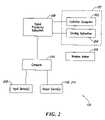
- FIG. 2is a block diagram of certain components of the system 100 .
- the excitation source and sensor array 102includes an excitation system 202 and a sensing subsystem 204 .
- the excitation system 202outputs electromagnetic energy to excite at least one wireless marker 206
- the sensing system 204receives electromagnetic energy from the marker. Details regarding the sensing subsystem 204 are provided below.
- a signal processing subsystem 208provides signals to the excitation subsystem 202 to generate the excitation signals. In the embodiment depicted herein, excitation signals in the range of 300 to 500 kilohertz may be used.
- the signal processing subsystem 208also receives signals from the sensing subsystem 204 .
- the signal processing subsystem 208filters, amplifies and correlates the signals received from the sensing subsystem 204 for use in a computer 210 .
- the computer 210may be any suitable computer, such as an industrial personal computer suitable for medical applications or environments.
- One or more input devices 212are coupled to the computer and receive user input. Examples of such input devices 212 include keyboards, microphones, mice/track balls, joy sticks, etc.
- the computergenerates output signals provided to output devices 214 . Examples of such output devices include the display device 108 , as well as speakers, printers, and network interfaces or subsystems to connect the computer with other systems or devices.
- FIG. 3Ais an exploded isometric view showing several components of the sensing subsystem 204 .
- the subsystem 204includes a sensing assembly 301 having a plurality of coils 302 formed on or carried by a panel 304 .
- the coilsare arranged in a sensor array 305 .
- the panel 304may be a substantially non-conductive sheet, such as KAPTON® produced by DuPont. KAPTON® is particularly useful when an extremely stable, tough, and thin film is required (such as to avoid radiation beam contamination), but the panel 304 may be made from other materials. For example, FR4 (epoxy-glass substrates), GETEK and Teflon-based substrates, and other commercially available materials can be used for the panel 304 .
- the panel 304may be a flat, highly planar structure, in other embodiments, the panel may be curved along at least one axis. In either embodiment, the panel is at least substantially locally planar such that the plane of one coil is at least substantially coplanar with the planes of adjacent coils.
- the angle between the plane defined by one coil relative to the planes defined by adjacent coilscan be from approximately 0° to 10°, and more generally is less than 5°. In some circumstances, however, one or more of the coils may be at an angle greater than 10° relative to other coils in the array.
- the sensing subsystem 204 shown in FIG. 3Acan further include a low-density foam spacer or core 320 laminated to the panel 304 .
- the foam core 320can be a closed-cell Rohacell foam.
- the foam core 320is preferably a stable layer that has a low coefficient of thermal expansion so that the shape of the sensing subsystem 204 and the relative orientation between the coils 302 remains within a defined range over an operating temperature range.
- the sensing subsystem 204can further include a first exterior cover 330 a on one side of the sensing subsystem and a second exterior cover 330 b on an opposing side.
- the first and second exterior covers 330 a - bcan be thin, thermally stable layers, such as Kevlar or Thermount films.
- Each of the first and second exterior covers 330 a - bcan include electric shielding 332 to block undesirable external electric fields from reaching the coils 302 .
- the electric shieldingis configured to prevent or minimize the presence of eddy currents caused by the coils 302 .
- the electric shieldingcan be a plurality of parallel legs of gold-plated, copper strips to define a comb-shaped shield in a configuration commonly called a Faraday shield. It will be appreciated that the shielding can be formed from other materials that are suitable for shielding.
- the electric shieldingcan be formed on the first and second exterior covers using printed circuit board manufacturing technology or other techniques.
- the panel 304 with the coils 302is laminated to the foam core 320 using an epoxy or another type of adhesive.
- the first and second exterior covers 330 a - bare similarly laminated to the assembly of the panel 304 and the foam core 320 .
- the laminated assemblyforms a rigid, lightweight structure that fixedly retains the arrangement of the coils 302 in a defined configuration over a large operating temperature range.
- the sensing subsystem 204does not substantially deflect across its surface during operation.
- the sensing subsystem 204can retain the array of coils 302 in the fixed position with a deflection of no greater than ⁇ 0.5 mm, and in some cases no more than ⁇ 0.3 mm.
- the stiffness of the sensing subsystem 204provides very accurate and repeatable monitoring of the precise location of leadless markers in real time.
- the sensing subsystem 204can also have a low mass per unit area in the plane of the sensor coils 302 .
- the “mass-density”is defined by the mass in a square centimeter column through the thickness of the sensing subsystem 204 orthogonal to the panel 304 .
- the sensing subsystem 204has a low-density in the region of the coils 302 to allow at least a portion of the sensing subsystem 204 to dwell in a radiation beam of a linear accelerator used for radiation oncology.
- the portion of the sensing subsystem 204 including the coils 302can have a mass density in the range of approximately 1.0 gram/cm 2 or less.
- the portion of the sensing subsystem that is to reside in the beam of a linear acceleratorhas a mass-density between approximately 0.1 grams/cm 2 and 0.5 grams/cm 2 , and often with an average mass-density of approximately 0.3 grams/cm 2 .
- the sensing subsystem 204can accordingly reside in a radiation beam of a linear accelerator without unduly attenuating or contaminating the beam.
- the sensing subsystem 204is configured to attenuate a radiation beam by approximately only 0.5% or less, and/or increase the skin dose in a patient by approximately 80%.
- the panel assemblycan increase the skin dose by approximately 50%.
- Several embodiments of the sensing subsystem 204can accordingly dwell in a radiation beam of a linear accelerator without unduly affecting the patient or producing large artifacts in x-ray films.
- the sensing subsystem 204can further include a plurality of source coils that are a component of the excitation subsystem 202 .
- One suitable array combining the sensing subsystem 204 with source coilsis disclosed in U.S. patent application Ser. No. 10/334,700, entitled PANEL-TYPE SENSOR/SOURCE ARRAY ASSEMBLY, filed on Dec. 30, 2002, which is herein incorporated by reference.
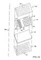
- FIG. 3Bfurther illustrates an embodiment of the sensing assembly 301 .
- the sensing assembly 301includes 32 sense coils 302 ; each coil 302 is associated with a separate channel 306 (shown individually as channels “Ch 0 through Ch 31 ”).
- the overall dimension of the panel 304can be approximately 40 cm by 54 cm, but the array 305 has a first dimension D 1 of approximately 40 cm and a second dimension D 2 of approximately 40 cm.
- the coil array 305can have other sizes or other configurations (e.g., circular) in alternative embodiments. Additionally, the coil array 305 can have more or fewer coils, such as 8-64 coils; the number of coils may moreover be a power of 2.
- the coils 302may be conductive traces or depositions of copper or another suitably conductive metal formed on the KAPTON® sheet. Each coil 302 has traces with a width of approximately 0.15 mm and a spacing between adjacent turns within each coil of approximately 0.15 mm.
- the coils 302can have approximately 15 to 90 turns, and in specific applications each coil has approximately 40 turns. Coils with less than 15 turns may not be sensitive enough for some applications, and coils with more than 90 turns may lead to excessive voltage from the source signal during excitation and excessive settling times resulting from the coil's lower self-resonant frequency. In other applications, however, the coils 302 can have less than 15 turns or more than 90 turns.
- the coils 302are arranged as square spirals, although other configurations may be employed, such as arrays of circles, interlocking hexagons, triangles, etc. Such square spirals utilize a large percentage of the surface area to improve the signal to noise ratio. Square coils also simplify design layout and modeling of the array compared to circular coils; for example, circular coils could waste surface area for linking magnetic flux from the wireless markers 206 .
- the coils 302have an inner diameter of approximately 40 mm, and an outer diameter of approximately 62 mm, although other dimensions are possible depending upon applications. Sensitivity may be improved with an inner diameter as close to an outer diameter as possible given manufacturing tolerances.
- the coils 32are identical to each other or at least configured substantially similarly.
- the pitch of the coils 302 in the coil array 305is a function of, at least in part, the minimum distance between the marker and the coil array.
- the coilsare arranged at a pitch of approximately 67 mm. This specific arrangement is particularly suitable when the wireless markers 206 are positioned approximately 7-27 cm from the sensing subsystem 204 . If the wireless markers are closer than 7 cm, then the sensing subsystem may include sense coils arranged at a smaller pitch. In general, a smaller pitch is desirable when wireless markers are to be sensed at a relatively short distance from the array of coils.
- the pitch of the coils 302for example, is approximately 50%-200% of the minimum distance between the marker and the array.
- the size and configuration of the coil array 305 and the coils 302 in the array 305depend on the frequency range in which they are to operate, the distance from the wireless markers 206 to the array, the signal strength of the markers, and several other factors. Those skilled in the relevant art will readily recognize that other dimensions and configurations may be employed depending, at least in part, on a desired frequency range and distance from the markers to the coils.
- the coil array 305is sized to provide a large aperture to measure the magnetic field emitted by the markers. It can be particularly challenging to accurately measure the signal emitted by an implantable marker that wirelessly transmits a marker signal in response to a wirelessly transmitted energy source because the marker signal is much smaller than the source signal and other magnetic fields in a room (e.g., magnetic fields from CRTs, etc.).
- the size of the coil array 305can be selected to preferentially measure the near field of the marker while mitigating interference from far field sources.
- the coil array 305is sized to have a maximum dimension D 1 or D 2 across the surface of the area occupied by the coils that is approximately 100% to 300% of a predetermined maximum sensing distance that the markers are to be spaced from the plane of the coils.
- the size of the coil array 305is determined by identifying the distance that the marker is to be spaced apart from the array to accurately measure the marker signal, and then arrange the coils so that the maximum dimension of the array is approximately 100%-300% of that distance.
- the maximum dimension of the coil array 305for example, can be approximately 200% of the sensing distance at which a marker is to be placed from the array 305 .
- the marker 206has a sensing distance of 20 cm and the maximum dimension of the array of coils 302 is between 20 cm and 60 cm, and more specifically 40 cm.
- a coil array with a maximum dimension as set forth aboveis particularly useful because it inherently provides a filter that mitigates interference from far field sources. It will be appreciated that in such a configuration the signal strength from the wireless marker decreases proportionally to the square of the distance. However, far field signals from electromagnetic noise generated by other systems in the environment decrease proportionally to the cube of the distance. Thus, if the wireless marker 206 is positioned approximately 20 cm from the sensing subsystem 204 , and a diameter or maximum dimension of the sensing subsystem is approximately 40 cm, signals from the wireless marker drop off at a square of the distance from the sensing subsystem while environmental noise drops off at a cube of the distance. The environmental noise is thus filtered by the sensing subassembly 204 to provide better signals to the signal processing subsystem 208 .
- the size or extent of the arraymay be limited by several factors.
- the size of the sensing assembly 301should not be so large as to mechanically interfere with the movable arm 104 ( FIG. 1 ), the base unit 106 ( FIG. 1 ), or other components, such as a patient couch, rotating gantry of a radiation therapy machine, etc. (not shown in FIG. 1 ).
- the size of the arraymay be limited by manufacturing considerations, such as a size of available panels 304 . Further, making a dimension or width of the coil array 305 larger than twice the distance to the wireless marker 206 may yield little performance improvement, but increase manufacturing costs and increase sensitivity to interference.
- the coils 302are electromagnetic field sensors that receive magnetic flux produced by the wireless marker 206 and in turn produce a current signal representing or proportional to an amount or magnitude of a component of the magnetic field through an inner portion or area of each coil.
- the field componentis also perpendicular to the plane of each coil 302 .
- each coilrepresents a separate channel, and thus each coil outputs signals to one of 32 output ports 306 .
- a preamplifier, described below,may be provided at each output port 306 . Placing preamplifiers (or impedance buffers) close to the coils minimizes capacitive loading on the coils, as described herein.
- the sensing assembly 301also includes conductive traces or conductive paths routing signals from each coil 302 to its corresponding output port 306 to thereby define a separate channel.
- the portsin turn are coupled to a connector 308 formed on the panel 304 to which an appropriately configured plug and associated cable may be attached.
- the sensing assembly 301may also include an onboard memory or other circuitry, such as shown by electrically erasable programmable read-only memory (EEPROM) 310 .
- EEPROMelectrically erasable programmable read-only memory
- the EEPROM 310may store manufacturing information such as a serial number, revision number, date of manufacture, and the like.
- the EEPROM 310may also store per-channel calibration data, as well as a record of run-time. The run-time will give an indication of the total radiation dose to which the array has been exposed, which can alert the system when a replacement sensing subsystem is required.
- additional coils or electromagnetic field sensorsmay be arranged perpendicular to the panel 304 to help determine a three-dimensional location of the wireless markers 206 .
- Adding coils or sensors in other dimensionscould increase total energy received from the wireless markers 206 by 3 dB.
- the complexity of such an arraymay increase three-fold or more. The inventors have found that three-dimensional coordinates of the wireless markers 206 may be found using the planar array shown in FIG. 3B .
- the coils 302may not be presented with an ideal open circuit. Instead, they may well be loaded by parasitic capacitance due largely to traces or conductive paths connecting the coils to the preamplifiers, as well as a damping network (described below) and an input impedance of the preamplifiers (although a low input impedance is preferred). These combined loads result in current flow when the coils 302 link with a changing magnetic flux. Any one sense coil 302 , then, links magnetic flux not only from the wireless marker 206 , but also from all the other sense coils as well. These current flows should be accounted for in downstream signal processing.
- a second considerationis the capacitive loading on the coils 302 .
- Capacitive loadingforms a resonant circuit with the coils themselves, which leads to excessive voltage overshoot when the excitation subsystem 202 is energized. Such a voltage overshoot should be limited or attenuated with a damping or “snubbing” network across the coils 302 .
- a greater capacitive loadingrequires a lower impedance damping network, which can result in substantial power dissipation and heating in the damping network.
- the preamplificationcan also be radiation tolerant because one application for the sensing subsystem 204 is with radiation therapy systems that use linear accelerators (LINAC). As a result, PNP bipolar transistors and discrete elements may be preferred. Further, a DC coupled circuit may be preferred if good settling times cannot be achieved with an AC circuit or output, particularly if analog to digital converters are unable to handle wide swings in an AC output signal.
- LINAClinear accelerators
- FIG. 4illustrates an embodiment of a snubbing network 402 having a differential amplifier 404 .
- the snubbing network 402includes two pairs of series coupled resistors and a capacitor bridging therebetween.
- a biasing circuit 406allows for adjustment of the differential amplifier, while a calibration input 408 allows both input legs of the differential amplifier to be balanced.
- the sensor coil 302is coupled to an input of the differential amplifier 404 , followed by a pair of high voltage protection diodes 410 .
- DC offsetmay be adjusted by a pair of resistors coupled to bases of the input transistors for the differential amplifier 404 (shown as having a zero value).
- Additional protection circuitryis provided, such as ESD protection diodes 412 at the output, as well as filtering capacitors (shown as having a 10 nF value).
- the signal processing subsystem 208 shown in FIG. 2is also referred to herein as a receiver.
- the receiver 208is operative to receive the signals from the sensing subsystem 204 and perform various signal processing. As set forth below, several of these signal processing techniques and associated structures significantly enhance the performance of the system 100 .
- the sense coils 32each provide a signal to a respective amplifier 404 .
- the amplifierthen provides the amplified signal to an associated analog-to-digital (A/D) converter 502 that converts the analog amplified signal into a digital representation, such as an 8-bit, 16-bit or 32-bit digital signal, depending upon design considerations.
- A/Danalog-to-digital
- an out-of band ditheris added to linearize the A/D converters 502 .
- the A/D converters 502are all clocked with a common clock signal to assure uniformity.
- the excitation 601 and response 603 waveformsare in the 300-500 KHz range, the A/D 502 would have to sample at a much higher frequency. In one embodiment, the A/D 502 samples at 16 MHz.
- the receiver 208receives a plurality of digital inputs from the A/D converters 502 .
- the receiver 208will act on the plurality of digital inputs to substantially eliminate noise, interference, and other “non-signal” effects to provide a high signal-to-noise ratio (SNR) plurality of digital outputs.
- SNRsignal-to-noise ratio
- These digital outputscan then be used to locate the marker using various locating techniques, such as the ones described in co-pending U.S. patent application Ser. No. 10/679,801 filed Oct. 6, 2003 entitled “Method and System for Marker Localization” and previously incorporated by reference.
- the excitation source 202emits, in one example, a triangular pulse of exciting energy at a frequency of about 300 to 500 kilohertz.
- FIG. 6shows one example of such an exciting pulse 601 that is emitted from the excitation source 202 .
- the exciting pulse 601has a duration of (T 1 -T 0 ). In one embodiment, the duration of the pulse 601 is 16 cycles, or for a signal at 400 KHz, about 40 microseconds. It can be appreciated that shorter or longer excitation pulses 601 may be used depending upon various design parameters.
- a triangular shaped pulseis used for the excitation in one embodiment, other shaped pulses, such as sinusoidal, sawtooth, or square wave excitation may be used. However, a triangular waveform will advantageously excite a marker that exhibits high inductive qualities. Further, because of the relatively high amplitude of the exciting pulse 601 , in some circumstances, the coils 302 of the sensing array 204 may be saturated. Further, when the exciting pulse 601 is being emitted, this would ordinarily be a source of significant noise to the coils 302 . Because of this, the operation of the system 100 utilizes a time multiplexed methodology where there is an excitation interval (T 1 -T 0 ) and a observation interval (T 2 -T 1 ).
- the excitation source 202stops emission and the sensing array 204 “listens” during the observation interval for the decaying ringing response 603 of the marker that has been excited.
- the ringing response 603will typically be a damped sinusoidal signal.
- This observation intervalis from time T 1 to time T 2 .
- the duration of the listening timeis 32 cycles, or for a signal at 400 KHz, about 80 microseconds.
- the combination of one excitation interval and its following observation intervalis referred to herein also as an excitation and observation subinterval.
- the excitation interval or observation intervalcan be adjusted to match the characteristics of the marker.
- the length of excitation interval or observation intervalis programmable (or automated) in the receiver 208 in order to optimize the sensing system 100 .
- FIG. 6is not drawn to scale and is merely illustrative.
- the response signals 603should be very similar to each other over various cycles of excitation and listening.
- the ringing response signals 603 that are sensed by the coils 302 of the sensing array 204can be merged over several hundred (or even thousands) excitation and listening cycles to improve the signal-to-noise ratio.
- response signals 603 over 100 millisecondsare averaged. This corresponds to roughly 1000 excitation and listening cycles.
- FIG. 7is a flow diagram of the overall process of one aspect of the present invention.
- the excitation source 202emits an exciting pulse 601 during an excitation interval.
- the sense coils 302sense the magnetic flux from the marker and provide data as inputs to the receiver 208 . This process is repeated for N iterations at box 705 and at box 707 , the signals input to the receiver 208 are averaged. Then, further processing is performed on the averaged inputs (see below).
- FIG. 7Additionally shown in FIG. 7 are other aspects of the present invention that may be optionally included. These include the implementation of a timing dither at box 711 , synchronization to a radiation source to eliminate interference at box 713 , and tuning the system 100 to the markers at box 709 . All of these aspects are discussed below.
- a correlation receiveris provided. As detailed below, it has been found that coherent receiver design is required to retain the relative polarity of each channel; it will also provide a 3 dB signal-to-noise performance improvement over an incoherent receiver.
- the response signals 603 that are received by the coils 302 and input into the receiverhave an unknown phase.
- the plurality of inputsare complex signals that each have an in-phase component and a quadrature component.
- the coherent receiver 208operates by extracting these components of the inputs.
- the phase shiftoccurs because the marker oftentimes does not have a resonant frequency that is precisely matched to the exciting pulse 601 . This is due to manufacturing tolerances and other factors. Because of the mismatch between the resonant frequency of the marker and the exciting pulse 601 , there will be a phase component of the signal sensed by the coils 302 . Further, in the presence of a strong magnetic signal, the markers may enter saturation in which case there is a phase shift due to losses in the marker.
- the phase shiftis substantially the same for all channels (i.e. each coil).
- the receiveranalyzes the signals from all of the channels and determines the most likely phase shift. Once the phase shift has been determined, this phase shift is corrected from the signals (such as by removal) and the real portion of the signal can be extracted. By performing the estimation and removal of the phase shift, this is substantially equivalent to coherent detection of the input signals.
- the coherent detectionis implemented by a digital signal processor 504 .
- the processing or analysiscan be done using programmable logic devices or even software running on a general purpose microprocessor.
- the receiver 208is adaptable to work in coordination with the excitation source to tune the system 100 to the specific characteristics of the marker.
- the excitation source 202has an adjustable frequency that can be tuned in accordance with analysis made by the receiver 208 .
- the receiver 208identifies the resonant frequency of the marker and provides that information to the excitation source 202 .
- the excitation source 202can then provide an exciting pulse 601 at a frequency that is closely matched to the resonant frequency of the marker. In this manner, better performance can be obtained by the system 100 .
- the determination of the resonant frequency of the markeris done in an iterative manner.
- the excitation source 202emits an exciting pulse 601 at a starting frequency F s .
- the starting frequencyis the lower range of possible resonant frequencies for the marker.
- the markermay have a wide marker resonant frequency range, for example, between 300-500 KHz. In this example, F s would then be 300 KHz.
- the frequency of the last emitted exciting pulse 601is incremented by an amount ⁇ F.
- the value of ⁇ Fis variable and depends upon the amount of resonant frequency accuracy desired for the system 100 . However, in one embodiment, ⁇ F is 2 KHz.
- the processis repeated until an ending frequency F e has been reached, for example 500 KHz.
- the frequencies of the exciting pulses ranging from F s to F e incremented by ⁇ Fconstitute a set of frequencies used to excite the marker. This set of frequencies may be large or small depending upon the ⁇ F, F s and F e .
- the spacing ⁇ Fis chosen as a fixed percentage bandwidth which has advantages in accuracy and/or processing time in certain applications particularly when the marker Q (rather than bandwidth) tends to be constant over a large frequency range.
- One such approachwould use a step size approximating the half power points of the marker frequency response.
- An examplewould be 1.5% steps resulting in a set consisting of: 300.00, 304.50, 309.07, . . . , 497.70, 505.16 kHz. It is understood that depending on the marker characteristics, other sets of excitation frequency may be used and the invention accepts an arbitrary arrangement of excitation frequencies.
- the data received for these iterationsis analyzed and the frequency for the emitting pulse 601 that provided the strongest (or otherwise best) signal is chosen as the resonant frequency of the marker at box 811 .
- the datamay also be referred to as a resonance set of plurality of inputs from the sense coils 302 . It can be appreciated that various methods for determining the resonant frequency may be possible and that only one implementation is given herein. The process above may be implemented, for example, in a resonant frequency and ring time control processor 510 .
- An alternative method of determining the resonant frequencywould interpolate the resultant response. This is particularly beneficial if the set of frequencies can guarantee multiple samples within a marker frequency response bandwidth. It is understood that this interpolation can be conducted in a number of ways, two examples of which are: a) parabolic fitting to find an estimate of the peak signal value and resonant frequency using neighboring data points to the one that represents the highest energy response; or, b) least squares error fitting to a multi-parameter model of the marker frequency response.
- the frequency rangemay be searched with a sparse set of excitation frequencies. Then, the excitation is iterated with a higher resolution set of frequencies in the neighborhood surrounding the candidate resonant frequency. Multiple iterations may be used in combination with interpolation.
- a first set of frequencies that are relatively sparsely spacedis used to excite the marker.
- the marker resonant frequencycan be narrowed down.
- a second set of frequencies that is more densely populated around the frequency band of interest (as ascertained by the first set of frequencies)is then used to excite the marker. This process can be repeated until the desired resolution of the marker resonant frequency has been obtained.
- Yet another embodiment of the process of FIG. 8would use wide-bandwidth excitation signals rather than sinusoidal signals that could excite multiple markers at once and then process the data, for example, using spectral estimation techniques, to determine the resonant frequencies of the markers.
- An example of such a signalwould be a high energy pulse, shaped to concentrate its energy in the frequency band of interest.
- the signalcould be repeated multiple times and averaging employed to improve the sensitivity of the resonant frequency estimation.
- Subsequent excitationis performed at the marker resonant frequency. Further, the receiver 208 is adjusted to correlate using the marker resonant frequency. This type of initial “calibration” by identifying the appropriate excitation frequency has been found to provide advantageous results.
- the receiver 208may be is adapted to the ring time of the marker.
- Various marker designsmay have varying ring times. For example, some markers made from certain materials may have ring times that extinguish quite rapidly compared to other markers made of differing material. Because of this, it may be advantageous to adjust the excitation pulse interval and the observation interval.
- the receiver 208has control circuitry that can control the operation of the excitation source 202 not only in the frequency domain, but also the time domain for the exciting pulse 601 .
- the receiver 208includes the resonant frequency and ring time control processor 510 that can modify the length of the observation interval. These parameters may be controlled according to preprogrammed instructions or manually by the operator of the system 100 through a user interface.
- the receiver 208also includes signal processing that uses a weighting of the data obtained during the observation interval. This is also referred to as applying a “window” filter to the observation interval.
- the windowis a Blackman window. The effect of the Blackman windowing is to improve the frequency selectivity of the receiver by reducing the effects of other markers tuned to different frequencies.
- the window filteris a “matched filter” that has a window that emulates the decay signature of the marker resonance.
- the effect of the matched filter windowingis to improve the sensitivity of the receiver.
- more than one markeris within the field of interest.
- three different markers having varying resonant frequenciesare used. Because of this, all three markers may have a response to the exciting pulse 601 at the resonant frequency of one of the markers.
- the signals from the two other markersmay add noise to the desired signal to be detected by the receiver. Because of this, as will be seen below, various windows can be applied to reduce the sensitivity of the receiver to other markers in the field of interest. Still, one drawback of the window filtering is decreased sensitivity to the marker of interest.
- the spectral datacan be simultaneously used to improve detection robustness of real markers versus noise spikes.
- the datais checked for consistency with the marker frequency response model.
- the systemcan reject candidates if the estimated bandwidth does not conform to the design parameters of the markers, for example, having a bandwidth outside of the acceptable manufacturing tolerance range. Additional model characteristics that may be distinguished include acceptable energy levels and acceptable separations of markers in the frequency domain.
- the systemcan also reject signals that are not coherent with the excitation signal phase as characterized by independent sources of noise in the environment.
- the system 100is used in proximity to a radiation source (such as a linear accelerator or a particle beam accelerator) that is used for the treatment of a human, such as during radiation therapy of a cancer patient.
- a radiation sourcesuch as a linear accelerator or a particle beam accelerator
- the system 100and particularly, the receiver 208 , the markers, or the sensing coils may be adversely interfered with by the operation of radiation source (not only the emitted radiation, but the circuitry of the radiation source itself). Therefore, the system 100 is adapted to operate when the radiation source is off. This can be coordinated, for example, by the use of a radiation control signal 506 (see FIG. 5 ) between the radiation source and the receiver 208 and/or system 100 .
- the control signaltravels to the receiver 208 and/or system 100 in order to put the system 100 into a “standby” mode.
- the radiation control signalmay be a simple binary signal.
- radiationmay be delivered by the radiation source in a 150 microsecond burst, occurring once every 10 milliseconds.
- one excitation and listening cyclemay take approximately 120 microseconds. Therefore, in one embodiment, after a radiation burst (when the system 100 is in standby mode), perhaps on the order of 80 excitation and listening cycles may be performed by the system 100 until the next radiation burst. This aspect of the present invention helps to negate the effect of any interference from the radiation source.
- the receiver 208includes a matched filter or other device (designated as radiation detector 512 ) that can detect the presence of interference due to the operation of the radiation delivery apparatus, or any other interfering device that operates in a pulsed mode. If such interference is detected, then the receiver 208 is operative to discard received input signals from the coils 302 that occurred in that timeframe.
- a matched filter or other devicedesignated as radiation detector 512
- the primary function of the receiver 208is to suppress noise and interference, while extracting signal from the received inputs.
- one of the techniques used for suppressing noiseis to perform averaging over several observation intervals.
- the source of noiseis periodic with a periodicity matched to that of the excitation and observation interval, then the noise not only will not be removed by averaging, but may indeed masquerade as signal.
- each excitation pulse 601is changed so as to not have a periodic repetition.
- the receiver 208includes a pseudo-random excitation dithering circuit 508 (see FIG. 5 ) that will randomly offset the start timing of each exciting pulse 601 relative to previous or future exciting pulses.
- the dithering circuit 508will offset the timing of each exciting pulse 601 by a random fraction of one period of the carrier frequency of the exciting pulse 601 , e.g., at 400 KHz dither from 0 to 2.5 microseconds. The effect of the dithering would spread out or “decohere” any periodic noise, turning the periodic noise into random noise that can be reduced by signal processing.
- Another method of achieving a similar resultis the randomly vary the polarity of each exciting pulse 601 .
- a first exciting pulsemay start with a positive going cycle, while a second exciting pulse may start with a negative going cycle.
- the first exciting pulsemay be 180 degrees out of phase with the second exciting pulse.
- This random polarity of the exciting pulses 601will also decohere any periodic noise, turning the periodic noise into random noise that can be eliminated by signal processing.
- Yet another method of achieving a similar resultis the randomly vary the starting phase of each exciting pulse 601 .
- a first exciting pulsemay start with zero relative phase, while a second exciting pulse may start at some random phase, while a third exciting pulse may start at another random phase.
- This random starting phase of the exciting pulses 601will also decohere any periodic noise, turning the periodic noise into random noise that can be eliminated by signal processing.
- the excitation intervals and observation intervalsare orthogonal temporally.
- the excitation intervalsare distinct from the observation intervals and there is no overlap.
- the receiver 208may be used with a substantially continuous excitation pulse.
- the excitation pulseis at a first frequency that is different from the returned frequency of the marker. This is referred to as frequency orthogonality. Because of this, the receiver 208 is adapted to have a narrow bandpass filter to suppress the excitation frequency and pass the returned frequency.
- the receiver 208uses coherent detection to increase SNR. Assume that the marker signal sensed by each channel is applied to a complex correlation receiver, identical over all channels. It is further assumed that any unknown phase shift in the marker signal is, in the absence of noise, common across all channels. If the actual phase—referred to as ⁇ —were known, coherent reception could be effected by counter-rotating each estimate by this phase and discarding the imaginary parts. This is a linear operation, and the only discarded component is the part of the noise that is orthogonal to the signal.
- the output of each channel at the end of each measurement intervalcan be modeled as in FIG. 9 , where A n is the signed scalar amplitude of the desired signal, ⁇ is an unknown phase shift common to all channels, and N n is a complex zero-mean, uncorrelated error in the measurement.
- the datacan be fit to the model in a least mean squares (LMS) sense as follows.
- This ambiguityis benign, as it applies to all channels in common for the measurement interval used. If post-detection averaging (or an equivalent operation) is intended, then this ambiguity will have to be resolved. When the SNR is high, this is easy to do by looking at the data.
- a ⁇ kA k ⁇ cos ⁇ ⁇ ⁇ + ⁇ k ⁇ cos ⁇ ⁇ ⁇ + ⁇ k ⁇ sin ⁇ ⁇ ⁇
- 2 ⁇ ⁇Arg ⁇ ⁇ [ ⁇ n ⁇ A n 2 + 2 ⁇ ⁇ A n ⁇ ⁇ n + ( ⁇ n 2 - ⁇ n 2 ) ] + ⁇ j ⁇ [ ⁇ n ⁇ 2 ⁇ A n ⁇ ⁇ n + 2 ⁇ ⁇ n ⁇ n ] ⁇ Eq . ⁇ 2
- the signal-to-noise ratio of the k th receiver channelis A k 2 /E ⁇ k 2 ⁇ ; the signal-to-noise across all channels is thus
- disjoint measurement intervalsare used for the estimates of A n and ⁇ . Let the data from the prior measurement interval be used to calculate ⁇ circumflex over ( ⁇ ) ⁇ , and let the data from the current measurement interval be used to calculate ⁇ n . This decorrelates the noise of the current measurement from the error in the estimate ⁇ circumflex over ( ⁇ ) ⁇ , and the resulting statistics are different in the following way.
- H b ⁇ ( s )[ RCs L b ⁇ Cs 2 + RCs + 1 ]
- the coupling between the current in the excitation source 202 and the voltage sensed by a sensing coil 302can be represented as a linear system shown in FIG. 10 .
- an upper path through box 1001is a direct feedthrough from source to sensor.
- a bottom pathis the response of the marker as seen by the sensing coil 302 .
- the transfer functionis thus:
- V sense ⁇ ( s ) I excitation ⁇ ( s )M se ⁇ s - M be ⁇ M sb R ⁇ s 2 ⁇ [ RCs L b ⁇ Cs 2 + RCs + 1 ]
- FIG. 11a time domain block diagram of the linear system model is given by FIG. 11 , where the filtering function is performed by convolution.
- the analytic representation of the sensed voltage in FIG. 11can be obtained.
- the receiverthus “sees” the following signal from the marker as [Eq. 4]:
- the received signalreverts to the marker natural frequency, weighted with a complex term that is a function of the difference frequency between excitation and resonance.
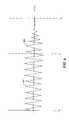
- FIG. 13shows the sensed response of a marker excited off-resonance.
- the same excitation pulseis used, but the marker is tuned to 88 kHz.
- the difference frequencyis clearly visible, as is the marker's natural frequency decay. It is also clear that the excitation selectivity is poor, as the response of the 88 kHz marker is suppressed only by a factor of about five.
- Marker saturationis problematic, presenting both analytic and practical difficulties. Qualitatively, the effects of marker saturation on the sensed voltage will be as follows.
- v ⁇ sense ⁇ ( t )[ M sb R ] ⁇ A sat 2 ⁇ s b ⁇ e s b ⁇ ( t - ⁇ e / 2 ) ; ⁇ e / 2 ⁇ t
- a satis a complex random variable
- ⁇ ethe duration of the excitation interval
- ⁇ tilde over (k) ⁇ (t)the complex correlation kernel
- repetition interval of the excitation pulsesis important for optimum performance. The selection may be made on an empirical basis and experimental data may be used to determine these parameters.
- An optimum correlation kernelrefers to a kernel which maximizes the SNR in a white noise environment. In an environment with multiple markers at different frequencies, there are better choices for kernels.
- the response of a receiver to a marker as the system frequency changesis examined, i.e. predicting receiver sensitivity as a function of frequency.
- the total measurement intervalis denoted as T 0 .
- the reference in this caseassumes CW excitation exhibiting constant energy E 0 over the measurement interval (same as the observation interval), independent of its duration, at the marker's resonant frequency.
- the sensed voltageis (using Eq. 4 in the second regime of operation, with ⁇ e ⁇ and s ⁇ ⁇ b )
- v ⁇ sense ⁇ ⁇ reference ⁇ ( t )⁇ j ⁇ [ M be ⁇ M sb R ] ⁇ E 0 2 ⁇ T 0 ⁇ [ 1 + ⁇ b s b ] 2 ⁇ s b 2 ⁇ e j ⁇ b ⁇ t ⁇ ⁇ j ⁇ [ M be ⁇ M sb R ] ⁇ E 0 2 ⁇ T 0 ⁇ s b 2 ⁇ e j ⁇ b ⁇ t
- an optimal coherent receiver matched to the markerwill exhibit a signal-to-noise ratio (see below analysis) of:
- Detection of the marker signal in the pulsed caseis restricted to the third regime of Eq. 4 to maintain (temporal) orthogonality with the excitation signal.
- the observation intervalis thus no larger than T 0 ⁇ e .
- the sensed voltage for t> ⁇ e /2is:
- v ⁇ sense ⁇ ( t )[ M be ⁇ M sb R ] ⁇ E e 2 ⁇ s b 2 ⁇ ⁇ b ⁇ P ⁇ ⁇ ( s b ) ⁇ e s b ⁇ t
- ⁇ circumflex over (P) ⁇ (s)is a Laplace transform of ⁇ tilde over (p) ⁇ *(t), properly normalized (see further detail below).
- the receiver observation intervalis ⁇ e /2 ⁇ t ⁇ , where ⁇ e is sixteen cycles of the 100 kHz carrier.
- the normalized pulse and its corresponding Laplace transformare thus
- k _ ⁇ ( t )2 ⁇ ⁇ r ⁇ e ⁇ r ⁇ ⁇ e ⁇ e s r ⁇ t ⁇ ⁇ ⁇ ( t - ⁇ e / 2 )
- K ⁇ ⁇ ( s b )- 2 ⁇ ⁇ r ⁇ e ⁇ r ⁇ ⁇ e ⁇ [ e ( s ⁇ - ⁇ r ) ⁇ ⁇ e / 2 s ⁇ - ⁇ r ]
- the efficiencyis determined by taking s ⁇ ⁇ b , whence
- a plot of the relative sensitivity over 300 kHz to 5000 kHzis shown in FIG. 14 .
- the relative sensitivity of an incoherent receiveris also plotted.
- Efficiencycan be used as a criterion when specifying excitation and observation intervals in an operational system.
- SNR reference⁇ [ M sb R ] ⁇ s b ⁇ 2 ⁇ ⁇ A sat ⁇ 2 ⁇ T 0 2 ⁇ ⁇ N 0
- SNR coherent⁇ [ M sb R ] ⁇ s b ⁇ 2 ⁇ ⁇ K ⁇ ⁇ ( s b ) ⁇ 2 ⁇ ⁇ A sat ⁇ 2 2 ⁇ ⁇ N 0
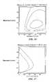
- FIGS. 15 , 16 , and 17can be used for design guidance when specifying the measurement timing of the system.
- constant energyprobably best matches the operational constraints of a practical system, whence the excitation interval should be in the range of 0.3-0.5 Q cycles and the observation interval about 0.6-1.0 Q cycles. Given the likelihood of marker saturation, the excitation interval should be biased towards the low side.
- the correlation kernelswere chosen to maximize the signal-to-noise ratio, and hence the efficiency.
- optimum choices for excitation and observation intervalswere developed for the single pulse and periodic pulse cases.
- optimum kernelsare optimum only in the sense of maximizing the signal-to-noise ratio in a white noise environment.
- use of alternate kernelspermits the tailoring of the selectivity of the receiver. Indeed, in the extreme case of all markers being driven to saturation, selectivity is a function of the kernel alone.
- the first case( FIG. 18 ) uses a rectangular kernel of 32 cycles; it is similar to the optimum case, but exhibits a slight loss of sensitivity (efficiency) at center frequency.
- the second case( FIG. 19 ) uses a Hamming weighted kernel of 32 cycles; it exhibits somewhat more loss of sensitivity at center frequency, but the selectivity is substantially improved.
- the third case( FIG. 20 ) uses a Blackman weighted kernel of 32 cycles.
- the sensitivityis degraded by about 6.5 dB from the first case.
- the sensing arrayhas thirty-two sensing coils 302 .
- the resulting output of the receiver 208is thirty-two “cleaned up” digital output signals. These digital output signals may then be used to locate the marker.
- each digital output signalis a measurement of one component of the magnetic field integrated over the aperture of the sensor array.
- the location systemdetermines the location of the marker (i.e., marker location) from a set or array of measurements taken from the sensors (i.e., set of actual measurements).
- the location systemcompares the set of actual measurements to sets of reference measurements for various known locations within a bounding volume (also referred to as a localization volume).
- the bounding volumedelimits the three-dimensional area in which the marker can be localized.
- a reference measurement for a known locationindicates the measurements to be expected from the sensors when the marker is located at that known location.
- the location systemBased on the comparisons, the location system identifies the set of reference measurements that most closely matches the set of actual measurements.
- the known location of the identified set of reference measurementsrepresents the known location that is closest to the marker location, which is referred to as the “closest known location.”
- the location systemuses sets of reference measurements for known locations near the closest known location to more accurately determine the marker location when it is not actually at one of the known locations.
- the location systemdetermines the marker location based on an interpolation of a set of calculated measurements from the sets of reference measurements of known locations near the closest known location.
- the location systemuses the set of reference measurements to find a known location that is close to the marker location to an accuracy that is dependent on the spacing of the known locations.
- the location systemthen uses an interpolation of sets of reference measurements at known locations near the closest known location to more accurately identify the marker location at a location between the known locations.
- each markermay be excited at resonance individually in a serial fashion and located sequentially.
- the use of multiple markersis contemplated by the present claimed invention.
- an array of hexagonally shaped sense coilsmay be formed on a planar array curved along at least one line to form a concave structure.
- the arrangement of coils on the panelmay form patterns besides the “cross” pattern shown in FIGS. 3A and 3B .
- the coilsmay be arranged on two or more panels or substrates, rather than the single panel described herein.
Landscapes
- Health & Medical Sciences (AREA)
- Life Sciences & Earth Sciences (AREA)
- Engineering & Computer Science (AREA)
- Heart & Thoracic Surgery (AREA)
- Molecular Biology (AREA)
- Biophysics (AREA)
- Pathology (AREA)
- Biomedical Technology (AREA)
- Human Computer Interaction (AREA)
- Medical Informatics (AREA)
- Physics & Mathematics (AREA)
- Surgery (AREA)
- Animal Behavior & Ethology (AREA)
- General Health & Medical Sciences (AREA)
- Public Health (AREA)
- Veterinary Medicine (AREA)
- Radiation-Therapy Devices (AREA)
- Magnetic Resonance Imaging Apparatus (AREA)
Abstract
Description
{circumflex over (φ)}=φ+ψ


that is constant across all channels, so the results remain ratiometrically accurate.
Here, Aeis the amplitude of the pulse, τeis its duration, and Eeis its energy. They are related according to Ee=Ae2 τe/2. Note that {tilde over (p)}(t) is not strictly analytic, except in the limit of arbitrarily long pulse duration. As a consequence, the integrals for the energy are not strictly equal unless τeis an integral number of periods; we assume this is always the case and does not materially affect the conclusions herein.
{tilde over (h)}b(t)=σbes
sΔ=−σb+jωb−jωe
- The peak of
FIG. 12 will flatten out to a value relatively independent of the excitation amplitude. - During the excitation interval, the effective resonant frequency of the marker will increase, and the effective Q will decrease.
- At the beginning of the observation interval (the third regime of Eq. 4), the marker will relax out of saturation and decay in a linear fashion according to its natural frequency. However, we have to expect that its initial conditions in this interval are, in practice, unknowable. In particular, the phase of the response in the observation interval has to be treated as a random variable.
- The peak of
- Case 1: The linear system model applies. The receiver sensitivity over frequency is referenced to a case in which the marker is excited with a constant energy CW signal, at its resonant frequency, where the energy in the pulse is equal to the energy in the CW excitation. In this case, at marker resonance, the relative sensitivity equals the efficiency. The use of a constant energy comparison is meaningful when the energy in the pulse is limited by, for example, thermal or average exposure considerations.
- Case 2: The linear system model applies. The receiver sensitivity over frequency is referenced to a case in which the marker is excited with a constant amplitude CW signal, at its resonant frequency, where the amplitude in the pulse is equal to the amplitude of the CW excitation. The use of a constant amplitude comparison is meaningful when the energy in the pulse is limited by, for example, source current or peak exposure considerations.
- Case 3: All markers in the field are saturated. This is generally not realistic when markers of different resonant frequencies are present, but the conclusions drawn are nonetheless instructive.
sr=−σr+jωr
where ωr=ωe=2π×105and σr=σb. It is assumed that σbis constant over all markers of interest. This implies that ωb/Q is constant.
Claims (15)
Priority Applications (1)
| Application Number | Priority Date | Filing Date | Title |
|---|---|---|---|
| US10/750,164US7684849B2 (en) | 2003-12-31 | 2003-12-31 | Marker localization sensing system synchronized with radiation source |
Applications Claiming Priority (1)
| Application Number | Priority Date | Filing Date | Title |
|---|---|---|---|
| US10/750,164US7684849B2 (en) | 2003-12-31 | 2003-12-31 | Marker localization sensing system synchronized with radiation source |
Publications (2)
| Publication Number | Publication Date |
|---|---|
| US20050154283A1 US20050154283A1 (en) | 2005-07-14 |
| US7684849B2true US7684849B2 (en) | 2010-03-23 |
Family
ID=34739094
Family Applications (1)
| Application Number | Title | Priority Date | Filing Date |
|---|---|---|---|
| US10/750,164Active2026-11-15US7684849B2 (en) | 2003-12-31 | 2003-12-31 | Marker localization sensing system synchronized with radiation source |
Country Status (1)
| Country | Link |
|---|---|
| US (1) | US7684849B2 (en) |
Cited By (44)
| Publication number | Priority date | Publication date | Assignee | Title |
|---|---|---|---|---|
| US20030192557A1 (en)* | 1998-05-14 | 2003-10-16 | David Krag | Systems and methods for locating and defining a target location within a human body |
| US20060079764A1 (en)* | 2004-07-23 | 2006-04-13 | Wright J N | Systems and methods for real time tracking of targets in radiation therapy and other medical applications |
| US20070055144A1 (en)* | 2004-08-12 | 2007-03-08 | Navotek Medical Ltd. | Medical Treatment System and Method |
| US20070265491A1 (en)* | 1998-05-14 | 2007-11-15 | Calypso Medical Technologies, Inc. | Systems and methods for stabilizing a target location within a human body |
| US20080262297A1 (en)* | 2004-04-26 | 2008-10-23 | Super Dimension Ltd. | System and Method for Image-Based Alignment of an Endoscope |
| US20090306728A1 (en)* | 2004-01-12 | 2009-12-10 | Calypso Medical Technologies, Inc. | Methods and apparatus for stimulating and/or sensing neurons in a patient |
| US20100160733A1 (en)* | 2002-04-17 | 2010-06-24 | Pinhas Gilboa | Endoscope Structures And Techniques For Navigating To A Target In Branched Structure |
| US20100198015A1 (en)* | 2003-09-15 | 2010-08-05 | Benny Greenburg | System Of Accessories For Use With Bronchoscopes |
| US20110198510A1 (en)* | 2004-08-12 | 2011-08-18 | Navotek Medical Ltd. | Localization of a radioactive source |
| US8164064B2 (en) | 2004-08-12 | 2012-04-24 | Navotek Medical Ltd. | Localization of a radioactive source within a body of a subject |
| US8452068B2 (en) | 2008-06-06 | 2013-05-28 | Covidien Lp | Hybrid registration method |
| US8473032B2 (en) | 2008-06-03 | 2013-06-25 | Superdimension, Ltd. | Feature-based registration method |
| US8611984B2 (en) | 2009-04-08 | 2013-12-17 | Covidien Lp | Locatable catheter |
| US8764725B2 (en) | 2004-02-09 | 2014-07-01 | Covidien Lp | Directional anchoring mechanism, method and applications thereof |
| US20140323852A1 (en)* | 2013-04-26 | 2014-10-30 | Medtronic Navigation, Inc. | Electromagnetic Coil Apparatuses for Surgical Navigation and Corresponding Methods |
| US8905920B2 (en) | 2007-09-27 | 2014-12-09 | Covidien Lp | Bronchoscope adapter and method |
| US8932207B2 (en) | 2008-07-10 | 2015-01-13 | Covidien Lp | Integrated multi-functional endoscopic tool |
| US9238151B2 (en) | 2004-07-23 | 2016-01-19 | Varian Medical Systems, Inc. | Dynamic/adaptive treatment planning for radiation therapy |
| US9575140B2 (en) | 2008-04-03 | 2017-02-21 | Covidien Lp | Magnetic interference detection system and method |
| US9586059B2 (en) | 2004-07-23 | 2017-03-07 | Varian Medical Systems, Inc. | User interface for guided radiation therapy |
| US9730764B2 (en) | 2015-10-02 | 2017-08-15 | Elucent Medical, Inc. | Signal tag detection components, devices, and systems |
| US9919165B2 (en) | 2014-05-07 | 2018-03-20 | Varian Medical Systems, Inc. | Systems and methods for fiducial to plan association |
| US10043284B2 (en) | 2014-05-07 | 2018-08-07 | Varian Medical Systems, Inc. | Systems and methods for real-time tumor tracking |
| US10154799B2 (en) | 2016-08-12 | 2018-12-18 | Elucent Medical, Inc. | Surgical device guidance and monitoring devices, systems, and methods |
| US10245119B2 (en) | 2015-10-02 | 2019-04-02 | Elucent Medical, Inc. | Signal tag detection components, devices, and systems |
| US10278779B1 (en) | 2018-06-05 | 2019-05-07 | Elucent Medical, Inc. | Exciter assemblies |
| US10418705B2 (en) | 2016-10-28 | 2019-09-17 | Covidien Lp | Electromagnetic navigation antenna assembly and electromagnetic navigation system including the same |
| US10426555B2 (en) | 2015-06-03 | 2019-10-01 | Covidien Lp | Medical instrument with sensor for use in a system and method for electromagnetic navigation |
| US10446931B2 (en) | 2016-10-28 | 2019-10-15 | Covidien Lp | Electromagnetic navigation antenna assembly and electromagnetic navigation system including the same |
| US10478254B2 (en) | 2016-05-16 | 2019-11-19 | Covidien Lp | System and method to access lung tissue |
| US10517505B2 (en) | 2016-10-28 | 2019-12-31 | Covidien Lp | Systems, methods, and computer-readable media for optimizing an electromagnetic navigation system |
| US10582834B2 (en) | 2010-06-15 | 2020-03-10 | Covidien Lp | Locatable expandable working channel and method |
| US10615500B2 (en) | 2016-10-28 | 2020-04-07 | Covidien Lp | System and method for designing electromagnetic navigation antenna assemblies |
| US10638952B2 (en) | 2016-10-28 | 2020-05-05 | Covidien Lp | Methods, systems, and computer-readable media for calibrating an electromagnetic navigation system |
| US10722311B2 (en) | 2016-10-28 | 2020-07-28 | Covidien Lp | System and method for identifying a location and/or an orientation of an electromagnetic sensor based on a map |
| US10751126B2 (en) | 2016-10-28 | 2020-08-25 | Covidien Lp | System and method for generating a map for electromagnetic navigation |
| US10792106B2 (en) | 2016-10-28 | 2020-10-06 | Covidien Lp | System for calibrating an electromagnetic navigation system |
| US10952593B2 (en) | 2014-06-10 | 2021-03-23 | Covidien Lp | Bronchoscope adapter |
| US11096605B2 (en) | 2015-03-31 | 2021-08-24 | Medtronic Navigation, Inc. | Modular coil assembly |
| US11219489B2 (en) | 2017-10-31 | 2022-01-11 | Covidien Lp | Devices and systems for providing sensors in parallel with medical tools |
| US11344382B2 (en) | 2014-01-24 | 2022-05-31 | Elucent Medical, Inc. | Systems and methods comprising localization agents |
| RU225674U1 (en)* | 2024-02-20 | 2024-05-02 | Общество с ограниченной ответственностью "Мироскан" | Device for detection and localization of metallic foreign inclusions in biological objects |
| US12226596B2 (en) | 2020-08-31 | 2025-02-18 | Bard Access Systems, Inc. | Magnetic field direction detection |
| US12383349B2 (en) | 2022-07-26 | 2025-08-12 | Elucent Medical, Inc. | Systems and methods for wireless localization |
Families Citing this family (5)
| Publication number | Priority date | Publication date | Assignee | Title |
|---|---|---|---|---|
| US7899513B2 (en)* | 2004-07-23 | 2011-03-01 | Calypso Medical Technologies, Inc. | Modular software system for guided radiation therapy |
| US8095203B2 (en)* | 2004-07-23 | 2012-01-10 | Varian Medical Systems, Inc. | Data processing for real-time tracking of a target in radiation therapy |
| WO2007035798A2 (en) | 2005-09-19 | 2007-03-29 | Calypso Medical Technologies, Inc. | Apparatus and methods for implanting objects, such as bronchoscopically implanting markers in the lung of patients |
| EP3882648B1 (en)* | 2020-03-18 | 2024-09-25 | Siemens Healthineers AG | Rf coil device for an mr or mr-pet imaging modality and method to determine the position and/or orientation and/or shape of such an rf coil device |
| US20210330390A1 (en)* | 2020-04-22 | 2021-10-28 | Medtronic Navigation, Inc. | System and method for navigation |
Citations (113)
| Publication number | Priority date | Publication date | Assignee | Title |
|---|---|---|---|---|
| US3577160A (en) | 1968-01-10 | 1971-05-04 | James E White | X-ray gauging apparatus with x-ray opaque markers in the x-ray path to indicate alignment of x-ray tube, subject and film |
| US3967161A (en) | 1972-06-14 | 1976-06-29 | Lichtblau G J | A multi-frequency resonant tag circuit for use with an electronic security system having improved noise discrimination |
| US3969629A (en) | 1975-03-14 | 1976-07-13 | Varian Associates | X-ray treatment machine having means for reducing secondary electron skin dose |
| US4023167A (en) | 1975-06-16 | 1977-05-10 | Wahlstrom Sven E | Radio frequency detection system and method for passive resonance circuits |
| US4114601A (en) | 1976-08-09 | 1978-09-19 | Micro Tec Instrumentation, Inc. | Medical and surgical implement detection system |
| US4123749A (en) | 1976-04-03 | 1978-10-31 | Bizerba-Werke Wilhelm Kraut Kg | Method and system for determining the presence of objects within a particular surveillance area, in particular for prevention of shoplifting |
| US4127110A (en) | 1976-05-24 | 1978-11-28 | Huntington Institute Of Applied Medical Research | Implantable pressure transducer |
| US4160971A (en) | 1975-05-02 | 1979-07-10 | National Research Development Corporation | Transponders |
| US4222374A (en) | 1978-06-16 | 1980-09-16 | Metal Bellows Corporation | Septum locating apparatus |
| US4260990A (en) | 1979-11-08 | 1981-04-07 | Lichtblau G J | Asymmetrical antennas for use in electronic security systems |
| US4393872A (en) | 1980-05-27 | 1983-07-19 | Eder Instrument Co., Inc. | Aspirating surgical forceps |
| US4618822A (en) | 1984-04-18 | 1986-10-21 | Position Orientation Systems, Ltd. | Displacement sensing device utilizing adjustable tuned circuit |
| US4633250A (en) | 1985-01-07 | 1986-12-30 | Allied Corporation | Coplanar antenna for proximate surveillance systems |
| US4642786A (en) | 1984-05-25 | 1987-02-10 | Position Orientation Systems, Ltd. | Method and apparatus for position and orientation measurement using a magnetic field and retransmission |
| US4643196A (en) | 1984-10-24 | 1987-02-17 | Hakko Electric Machine Works Co., Ltd. | Biopsy needle set |
| US4696287A (en) | 1985-02-26 | 1987-09-29 | Hortmann Gmbh | Transmission system for implanted hearing aids |
| US4795995A (en) | 1984-09-17 | 1989-01-03 | Progressive Dynamics, Inc. | Method and apparatus for producing electromagnetic surveillance fields |
| US4799495A (en) | 1987-03-20 | 1989-01-24 | National Standard Company | Localization needle assembly |
| FR2635259A1 (en) | 1988-08-11 | 1990-02-16 | Marthan Erick | Apparatus for locating the position of a metal piece in a human or animal body |
| US4909789A (en) | 1986-03-28 | 1990-03-20 | Olympus Optical Co., Ltd. | Observation assisting forceps |
| US4936823A (en) | 1988-05-04 | 1990-06-26 | Triangle Research And Development Corp. | Transendoscopic implant capsule |
| US4994079A (en) | 1989-07-28 | 1991-02-19 | C. R. Bard, Inc. | Grasping forceps |
| US5019713A (en) | 1989-04-10 | 1991-05-28 | Siemens Medical Laboratories, Inc. | Radiation therapy device with moveable aperture plate |
| US5031634A (en) | 1990-01-19 | 1991-07-16 | Beth Israel Hospital Assoc., Inc. | Adjustable biopsy needle-guide device |
| US5057095A (en) | 1989-11-16 | 1991-10-15 | Fabian Carl E | Surgical implement detector utilizing a resonant marker |
| US5062847A (en) | 1990-12-31 | 1991-11-05 | Barnes William E | Laparoscopic retractor |
| US5095224A (en) | 1990-08-31 | 1992-03-10 | Siemens-Pacesetter, Inc. | Interrupted resonance energy transfer system |
| US5099845A (en) | 1989-05-24 | 1992-03-31 | Micronix Pty Ltd. | Medical instrument location means |
| US5107862A (en) | 1991-05-06 | 1992-04-28 | Fabian Carl E | Surgical implement detector utilizing a powered marker |
| US5142292A (en) | 1991-08-05 | 1992-08-25 | Checkpoint Systems, Inc. | Coplanar multiple loop antenna for electronic article surveillance systems |
| US5170055A (en) | 1990-07-25 | 1992-12-08 | Care Wise Medical Products Corporation | Radiation detecting biopsy probe |
| US5189690A (en) | 1991-09-09 | 1993-02-23 | Ronald Samuel | Fluoroscopy orientation device |
| EP0531081A1 (en) | 1991-09-03 | 1993-03-10 | General Electric Company | Tracking system to follow the position and orientation of a device with radiofrequency fields |
| FR2686499A1 (en) | 1992-01-28 | 1993-07-30 | Technomed Int Sa | APPARATUS FOR TREATING A TARGET, SUCH AS A DAMAGE WITHIN THE BODY OF A MAMMAL, PARTICULARLY A HUMAN BEING, USING A MARKING ELEMENT IMPLANTED IN OR IN THE VICINITY OF THE TARGET TO CONTROL THERAPY OF THE SAME TARGET. |
| US5233990A (en) | 1992-01-13 | 1993-08-10 | Gideon Barnea | Method and apparatus for diagnostic imaging in radiation therapy |
| US5285772A (en) | 1991-10-24 | 1994-02-15 | Siemens Aktiengesellschaft | Therapy apparatus for treating a patient with focused acoustic waves |
| US5325873A (en) | 1992-07-23 | 1994-07-05 | Abbott Laboratories | Tube placement verifier system |
| US5353804A (en) | 1990-09-18 | 1994-10-11 | Peb Biopsy Corporation | Method and device for percutaneous exisional breast biopsy |
| US5386191A (en) | 1993-03-01 | 1995-01-31 | The Regents Of The University Of California | RF coil providing reduced obstruction access to image volume in transverse magnet MRI system |
| US5396905A (en) | 1994-03-29 | 1995-03-14 | General Electric Company | Surgical drape with integral MRI coil |
| US5396889A (en) | 1992-09-07 | 1995-03-14 | Hitachi Medical Corporation | Stereotactic radiosurgery method and apparatus |
| US5400787A (en) | 1993-11-24 | 1995-03-28 | Magna-Lab, Inc. | Inflatable magnetic resonance imaging sensing coil assembly positioning and retaining device and method for using the same |
| US5409004A (en) | 1993-06-11 | 1995-04-25 | Cook Incorporated | Localization device with radiopaque markings |
| US5423334A (en) | 1993-02-01 | 1995-06-13 | C. R. Bard, Inc. | Implantable medical device characterization system |
| US5425367A (en) | 1991-09-04 | 1995-06-20 | Navion Biomedical Corporation | Catheter depth, position and orientation location system |
| US5425382A (en) | 1993-09-14 | 1995-06-20 | University Of Washington | Apparatus and method for locating a medical tube in the body of a patient |
| US5509900A (en) | 1992-03-02 | 1996-04-23 | Kirkman; Thomas R. | Apparatus and method for retaining a catheter in a blood vessel in a fixed position |
| US5528651A (en) | 1994-06-09 | 1996-06-18 | Elekta Instrument Ab | Positioning device and method for radiation treatment |
| US5559435A (en) | 1994-07-01 | 1996-09-24 | Mitsubishi Denki Kabushiki Kaisha | Inclined magnetic field generator |
| US5621779A (en) | 1995-07-20 | 1997-04-15 | Siemens Medical Systems, Inc. | Apparatus and method for delivering radiation to an object and for displaying delivered radiation |
| US5638819A (en) | 1995-08-29 | 1997-06-17 | Manwaring; Kim H. | Method and apparatus for guiding an instrument to a target |
| US5664582A (en) | 1992-11-17 | 1997-09-09 | Szymaitis; Dennis W. | Method for detecting, distinguishing and counting objects |
| US5680106A (en) | 1995-10-27 | 1997-10-21 | International Business Machines Corporation | Multibit tag with stepwise variable frequencies |
| US5697384A (en) | 1993-03-26 | 1997-12-16 | Surge Miyawaki Co., Ltd. | Internal identification apparatus for animals |
| US5707362A (en) | 1992-04-15 | 1998-01-13 | Yoon; Inbae | Penetrating instrument having an expandable anchoring portion for triggering protrusion of a safety member and/or retraction of a penetrating member |
| US5707390A (en) | 1990-03-02 | 1998-01-13 | General Surgical Innovations, Inc. | Arthroscopic retractors |
| US5727552A (en) | 1996-01-11 | 1998-03-17 | Medtronic, Inc. | Catheter and electrical lead location system |
| US5729129A (en)* | 1995-06-07 | 1998-03-17 | Biosense, Inc. | Magnetic location system with feedback adjustment of magnetic field generator |
| US5735795A (en) | 1995-07-20 | 1998-04-07 | Picker International, Inc. | Marker for magnetic resonance imaging |
| US5745545A (en) | 1996-08-16 | 1998-04-28 | Siemens Medical Systems, Inc. | Alignment system and method for intra-operative radiation therapy |
| US5764052A (en) | 1995-06-16 | 1998-06-09 | Pacesetter, Inc. | Coil return energy measurement magnetic field sensor and method thereof |
| US5769861A (en) | 1995-09-28 | 1998-06-23 | Brainlab Med. Computersysteme Gmbh | Method and devices for localizing an instrument |
| US5810851A (en) | 1996-03-05 | 1998-09-22 | Yoon; Inbae | Suture spring device |
| US5815076A (en) | 1996-01-16 | 1998-09-29 | Sensormatic Electronics Corporation | Pulsed-signal magnetomechanical electronic article surveillance system with improved damping of transmitting antenna |
| US5840148A (en) | 1995-06-30 | 1998-11-24 | Bio Medic Data Systems, Inc. | Method of assembly of implantable transponder |
| US5868673A (en) | 1995-03-28 | 1999-02-09 | Sonometrics Corporation | System for carrying out surgery, biopsy and ablation of a tumor or other physical anomaly |
| US5879297A (en) | 1997-05-08 | 1999-03-09 | Lucent Medical Systems, Inc. | System and method to determine the location and orientation of an indwelling medical device |
| US5910144A (en) | 1998-01-09 | 1999-06-08 | Endovascular Technologies, Inc. | Prosthesis gripping system and method |
| US5928137A (en) | 1996-05-03 | 1999-07-27 | Green; Philip S. | System and method for endoscopic imaging and endosurgery |
| US5951481A (en) | 1996-09-20 | 1999-09-14 | Critikon Company, L.L.C. | Apparatus and method for non-invasive measurement of a substance |
| US5989265A (en) | 1995-03-08 | 1999-11-23 | Bouquet De La Joliniere; Jean Henri | Device for pinpointing suspect lesions of the breast and apparatus for positioning it |
| US6026818A (en) | 1998-03-02 | 2000-02-22 | Blair Port Ltd. | Tag and detection device |
| US6059734A (en) | 1995-01-06 | 2000-05-09 | Yoon; Inbae | Methods of collecting tissue at obstructed anatomical sites |
| US6061644A (en) | 1997-12-05 | 2000-05-09 | Northern Digital Incorporated | System for determining the spatial position and orientation of a body |
| US6067465A (en) | 1997-11-26 | 2000-05-23 | General Electric Company | System and method for detecting and tracking reference position changes with linear phase shift in magnetic resonance imaging |
| US6076008A (en) | 1990-10-19 | 2000-06-13 | St. Louis University | System for indicating the position of a surgical probe within a head on an image of the head |
| US6081238A (en) | 1995-05-30 | 2000-06-27 | Sensormatic Electronics Corporation | EAS system antenna configuration for providing improved interrogation field distribution |
| US6082366A (en) | 1995-09-05 | 2000-07-04 | Aesculap Meditec Gmbh | Method and arrangement for determining the position of a marker in an organic cavity |
| US6129668A (en) | 1997-05-08 | 2000-10-10 | Lucent Medical Systems, Inc. | System and method to determine the location and orientation of an indwelling medical device |
| US6165135A (en) | 1999-07-14 | 2000-12-26 | Neff; Samuel R. | System and method of interrogating implanted passive resonant-circuit devices |
| US6198963B1 (en) | 1996-07-17 | 2001-03-06 | Biosense, Inc. | Position confirmation with learn and test functions |
| US6230038B1 (en) | 1999-02-01 | 2001-05-08 | International Business Machines Corporation | Imaging of internal structures of living bodies by sensing implanted magnetic devices |
| US6246900B1 (en) | 1995-05-04 | 2001-06-12 | Sherwood Services Ag | Head band for frameless stereotactic registration |
| US6307473B1 (en) | 1999-08-24 | 2001-10-23 | Sensormatic Electronics Corporation | Electronic article surveillance transmitter control using target range |
| US6363940B1 (en) | 1998-05-14 | 2002-04-02 | Calypso Medical Technologies, Inc. | System and method for bracketing and removing tissue |
| US6371379B1 (en) | 1995-07-17 | 2002-04-16 | Flying Null Limited | Magnetic tags or markers |
| US6380732B1 (en) | 1997-02-13 | 2002-04-30 | Super Dimension Ltd. | Six-degree of freedom tracking system having a passive transponder on the object being tracked |
| US6385482B1 (en) | 1996-03-27 | 2002-05-07 | Mednetix Ag | Device and process for determining position |
| US6405072B1 (en) | 1991-01-28 | 2002-06-11 | Sherwood Services Ag | Apparatus and method for determining a location of an anatomical target with reference to a medical apparatus |
| US6416520B1 (en) | 1999-04-23 | 2002-07-09 | Sherwood Services Ag | Microdrive for probes |
| US6474341B1 (en) | 1999-10-28 | 2002-11-05 | Surgical Navigation Technologies, Inc. | Surgical communication and power system |
| US20020193685A1 (en)* | 2001-06-08 | 2002-12-19 | Calypso Medical, Inc. | Guided Radiation Therapy System |
| US20030041866A1 (en) | 1999-12-17 | 2003-03-06 | Medtronic, Inc. | Virtual remote monitor, alert, diagnostics and programming for implantable medical device systems |
| US6534982B1 (en) | 1998-12-23 | 2003-03-18 | Peter D. Jakab | Magnetic resonance scanner with electromagnetic position and orientation tracking device |
| US20030052785A1 (en) | 2001-09-14 | 2003-03-20 | Margo Gisselberg | Miniature resonating marker assembly |
| US20030066537A1 (en) | 2001-10-10 | 2003-04-10 | Fabian Carl E. | Surgical implement detection system |
| US6553326B1 (en) | 2000-04-07 | 2003-04-22 | Northern Digital Inc. | Errors in systems using magnetic fields to locate objects |
| US20030088178A1 (en) | 2001-11-02 | 2003-05-08 | Owens Timothy R | Method and apparatus for computer modified magnetic resonance imaging |
| US6564807B1 (en) | 1997-02-26 | 2003-05-20 | Alfred E. Mann Foundation For Scientific Research | System of implantable devices for monitoring and/or affecting body parameters |
| US20030105394A1 (en) | 2001-12-03 | 2003-06-05 | Fabian Carl R. | Portable surgical implement detector |
| US20030122653A1 (en) | 2001-12-20 | 2003-07-03 | Dimmer Steven C. | System for excitation of a leadless miniature marker |
| US20030149353A1 (en) | 2001-04-14 | 2003-08-07 | Andreas Boos | Measurement of patient data requiring operator and patient identification |
| US6611141B1 (en) | 1998-12-23 | 2003-08-26 | Howmedica Leibinger Inc | Hybrid 3-D probe tracked by multiple sensors |
| US20030192557A1 (en) | 1998-05-14 | 2003-10-16 | David Krag | Systems and methods for locating and defining a target location within a human body |
| US6701179B1 (en) | 1999-10-28 | 2004-03-02 | Michael A. Martinelli | Coil structures and methods for generating magnetic fields |
| US20040101073A1 (en)* | 2002-11-20 | 2004-05-27 | Sanyo Electric Co., Ltd. | Method and apparatus for estimating response characteristic, and receiving method and receiver utilizing the same |
| US20040125916A1 (en)* | 2002-12-30 | 2004-07-01 | Herron Matthew A. | Panel-type sensor/source array assembly |
| US6822570B2 (en) | 2001-12-20 | 2004-11-23 | Calypso Medical Technologies, Inc. | System for spatially adjustable excitation of leadless miniature marker |
| US6838990B2 (en) | 2001-12-20 | 2005-01-04 | Calypso Medical Technologies, Inc. | System for excitation leadless miniature marker |
| US6905245B2 (en) | 2002-07-09 | 2005-06-14 | Agfa-Gevaert | Contrast phantom |
| DE19914455B4 (en) | 1999-03-30 | 2005-07-14 | Siemens Ag | Method for determining the movement of an organ or therapeutic area of a patient and a system suitable for this purpose |
| US6977504B2 (en) | 2003-12-31 | 2005-12-20 | Calypso Medical Technologies, Inc. | Receiver used in marker localization sensing system using coherent detection |
| US7026927B2 (en)* | 2003-12-31 | 2006-04-11 | Calypso Medical Technologies, Inc. | Receiver used in marker localization sensing system and having dithering in excitation pulses |
- 2003
- 2003-12-31USUS10/750,164patent/US7684849B2/enactiveActive
Patent Citations (124)
| Publication number | Priority date | Publication date | Assignee | Title |
|---|---|---|---|---|
| US3577160A (en) | 1968-01-10 | 1971-05-04 | James E White | X-ray gauging apparatus with x-ray opaque markers in the x-ray path to indicate alignment of x-ray tube, subject and film |
| US3967161A (en) | 1972-06-14 | 1976-06-29 | Lichtblau G J | A multi-frequency resonant tag circuit for use with an electronic security system having improved noise discrimination |
| US3969629A (en) | 1975-03-14 | 1976-07-13 | Varian Associates | X-ray treatment machine having means for reducing secondary electron skin dose |
| US4160971A (en) | 1975-05-02 | 1979-07-10 | National Research Development Corporation | Transponders |
| US4023167A (en) | 1975-06-16 | 1977-05-10 | Wahlstrom Sven E | Radio frequency detection system and method for passive resonance circuits |
| US4123749A (en) | 1976-04-03 | 1978-10-31 | Bizerba-Werke Wilhelm Kraut Kg | Method and system for determining the presence of objects within a particular surveillance area, in particular for prevention of shoplifting |
| US4127110A (en) | 1976-05-24 | 1978-11-28 | Huntington Institute Of Applied Medical Research | Implantable pressure transducer |
| US4114601A (en) | 1976-08-09 | 1978-09-19 | Micro Tec Instrumentation, Inc. | Medical and surgical implement detection system |
| US4222374A (en) | 1978-06-16 | 1980-09-16 | Metal Bellows Corporation | Septum locating apparatus |
| US4260990A (en) | 1979-11-08 | 1981-04-07 | Lichtblau G J | Asymmetrical antennas for use in electronic security systems |
| US4393872A (en) | 1980-05-27 | 1983-07-19 | Eder Instrument Co., Inc. | Aspirating surgical forceps |
| US4618822A (en) | 1984-04-18 | 1986-10-21 | Position Orientation Systems, Ltd. | Displacement sensing device utilizing adjustable tuned circuit |
| US4642786A (en) | 1984-05-25 | 1987-02-10 | Position Orientation Systems, Ltd. | Method and apparatus for position and orientation measurement using a magnetic field and retransmission |
| US4795995A (en) | 1984-09-17 | 1989-01-03 | Progressive Dynamics, Inc. | Method and apparatus for producing electromagnetic surveillance fields |
| US4643196A (en) | 1984-10-24 | 1987-02-17 | Hakko Electric Machine Works Co., Ltd. | Biopsy needle set |
| US4633250A (en) | 1985-01-07 | 1986-12-30 | Allied Corporation | Coplanar antenna for proximate surveillance systems |
| US4696287A (en) | 1985-02-26 | 1987-09-29 | Hortmann Gmbh | Transmission system for implanted hearing aids |
| US4909789A (en) | 1986-03-28 | 1990-03-20 | Olympus Optical Co., Ltd. | Observation assisting forceps |
| US4799495A (en) | 1987-03-20 | 1989-01-24 | National Standard Company | Localization needle assembly |
| US4936823A (en) | 1988-05-04 | 1990-06-26 | Triangle Research And Development Corp. | Transendoscopic implant capsule |
| FR2635259A1 (en) | 1988-08-11 | 1990-02-16 | Marthan Erick | Apparatus for locating the position of a metal piece in a human or animal body |
| US5019713A (en) | 1989-04-10 | 1991-05-28 | Siemens Medical Laboratories, Inc. | Radiation therapy device with moveable aperture plate |
| US5099845A (en) | 1989-05-24 | 1992-03-31 | Micronix Pty Ltd. | Medical instrument location means |
| US4994079A (en) | 1989-07-28 | 1991-02-19 | C. R. Bard, Inc. | Grasping forceps |
| US5057095A (en) | 1989-11-16 | 1991-10-15 | Fabian Carl E | Surgical implement detector utilizing a resonant marker |
| US5031634A (en) | 1990-01-19 | 1991-07-16 | Beth Israel Hospital Assoc., Inc. | Adjustable biopsy needle-guide device |
| US5707390A (en) | 1990-03-02 | 1998-01-13 | General Surgical Innovations, Inc. | Arthroscopic retractors |
| US5170055A (en) | 1990-07-25 | 1992-12-08 | Care Wise Medical Products Corporation | Radiation detecting biopsy probe |
| US5095224A (en) | 1990-08-31 | 1992-03-10 | Siemens-Pacesetter, Inc. | Interrupted resonance energy transfer system |
| US5353804A (en) | 1990-09-18 | 1994-10-11 | Peb Biopsy Corporation | Method and device for percutaneous exisional breast biopsy |
| US6076008A (en) | 1990-10-19 | 2000-06-13 | St. Louis University | System for indicating the position of a surgical probe within a head on an image of the head |
| US5062847A (en) | 1990-12-31 | 1991-11-05 | Barnes William E | Laparoscopic retractor |
| US6405072B1 (en) | 1991-01-28 | 2002-06-11 | Sherwood Services Ag | Apparatus and method for determining a location of an anatomical target with reference to a medical apparatus |
| US5107862A (en) | 1991-05-06 | 1992-04-28 | Fabian Carl E | Surgical implement detector utilizing a powered marker |
| US5142292A (en) | 1991-08-05 | 1992-08-25 | Checkpoint Systems, Inc. | Coplanar multiple loop antenna for electronic article surveillance systems |
| EP0531081A1 (en) | 1991-09-03 | 1993-03-10 | General Electric Company | Tracking system to follow the position and orientation of a device with radiofrequency fields |
| US5377678A (en) | 1991-09-03 | 1995-01-03 | General Electric Company | Tracking system to follow the position and orientation of a device with radiofrequency fields |
| US5425367A (en) | 1991-09-04 | 1995-06-20 | Navion Biomedical Corporation | Catheter depth, position and orientation location system |
| US5189690A (en) | 1991-09-09 | 1993-02-23 | Ronald Samuel | Fluoroscopy orientation device |
| US5285772A (en) | 1991-10-24 | 1994-02-15 | Siemens Aktiengesellschaft | Therapy apparatus for treating a patient with focused acoustic waves |
| US5233990A (en) | 1992-01-13 | 1993-08-10 | Gideon Barnea | Method and apparatus for diagnostic imaging in radiation therapy |
| FR2686499A1 (en) | 1992-01-28 | 1993-07-30 | Technomed Int Sa | APPARATUS FOR TREATING A TARGET, SUCH AS A DAMAGE WITHIN THE BODY OF A MAMMAL, PARTICULARLY A HUMAN BEING, USING A MARKING ELEMENT IMPLANTED IN OR IN THE VICINITY OF THE TARGET TO CONTROL THERAPY OF THE SAME TARGET. |
| US5509900A (en) | 1992-03-02 | 1996-04-23 | Kirkman; Thomas R. | Apparatus and method for retaining a catheter in a blood vessel in a fixed position |
| US5707362A (en) | 1992-04-15 | 1998-01-13 | Yoon; Inbae | Penetrating instrument having an expandable anchoring portion for triggering protrusion of a safety member and/or retraction of a penetrating member |
| US5325873A (en) | 1992-07-23 | 1994-07-05 | Abbott Laboratories | Tube placement verifier system |
| US5396889A (en) | 1992-09-07 | 1995-03-14 | Hitachi Medical Corporation | Stereotactic radiosurgery method and apparatus |
| US5664582A (en) | 1992-11-17 | 1997-09-09 | Szymaitis; Dennis W. | Method for detecting, distinguishing and counting objects |
| US5423334A (en) | 1993-02-01 | 1995-06-13 | C. R. Bard, Inc. | Implantable medical device characterization system |
| US5386191A (en) | 1993-03-01 | 1995-01-31 | The Regents Of The University Of California | RF coil providing reduced obstruction access to image volume in transverse magnet MRI system |
| US5697384A (en) | 1993-03-26 | 1997-12-16 | Surge Miyawaki Co., Ltd. | Internal identification apparatus for animals |
| US5409004A (en) | 1993-06-11 | 1995-04-25 | Cook Incorporated | Localization device with radiopaque markings |
| US5425382A (en) | 1993-09-14 | 1995-06-20 | University Of Washington | Apparatus and method for locating a medical tube in the body of a patient |
| US5400787A (en) | 1993-11-24 | 1995-03-28 | Magna-Lab, Inc. | Inflatable magnetic resonance imaging sensing coil assembly positioning and retaining device and method for using the same |
| US5396905A (en) | 1994-03-29 | 1995-03-14 | General Electric Company | Surgical drape with integral MRI coil |
| US5528651A (en) | 1994-06-09 | 1996-06-18 | Elekta Instrument Ab | Positioning device and method for radiation treatment |
| US5559435A (en) | 1994-07-01 | 1996-09-24 | Mitsubishi Denki Kabushiki Kaisha | Inclined magnetic field generator |
| US6059734A (en) | 1995-01-06 | 2000-05-09 | Yoon; Inbae | Methods of collecting tissue at obstructed anatomical sites |
| US5989265A (en) | 1995-03-08 | 1999-11-23 | Bouquet De La Joliniere; Jean Henri | Device for pinpointing suspect lesions of the breast and apparatus for positioning it |
| US5868673A (en) | 1995-03-28 | 1999-02-09 | Sonometrics Corporation | System for carrying out surgery, biopsy and ablation of a tumor or other physical anomaly |
| US6246900B1 (en) | 1995-05-04 | 2001-06-12 | Sherwood Services Ag | Head band for frameless stereotactic registration |
| US6081238A (en) | 1995-05-30 | 2000-06-27 | Sensormatic Electronics Corporation | EAS system antenna configuration for providing improved interrogation field distribution |
| US5729129A (en)* | 1995-06-07 | 1998-03-17 | Biosense, Inc. | Magnetic location system with feedback adjustment of magnetic field generator |
| US5764052A (en) | 1995-06-16 | 1998-06-09 | Pacesetter, Inc. | Coil return energy measurement magnetic field sensor and method thereof |
| US5840148A (en) | 1995-06-30 | 1998-11-24 | Bio Medic Data Systems, Inc. | Method of assembly of implantable transponder |
| US6371379B1 (en) | 1995-07-17 | 2002-04-16 | Flying Null Limited | Magnetic tags or markers |
| US5735795A (en) | 1995-07-20 | 1998-04-07 | Picker International, Inc. | Marker for magnetic resonance imaging |
| US5621779A (en) | 1995-07-20 | 1997-04-15 | Siemens Medical Systems, Inc. | Apparatus and method for delivering radiation to an object and for displaying delivered radiation |
| US5638819A (en) | 1995-08-29 | 1997-06-17 | Manwaring; Kim H. | Method and apparatus for guiding an instrument to a target |
| US6082366A (en) | 1995-09-05 | 2000-07-04 | Aesculap Meditec Gmbh | Method and arrangement for determining the position of a marker in an organic cavity |
| US5769861A (en) | 1995-09-28 | 1998-06-23 | Brainlab Med. Computersysteme Gmbh | Method and devices for localizing an instrument |
| US5680106A (en) | 1995-10-27 | 1997-10-21 | International Business Machines Corporation | Multibit tag with stepwise variable frequencies |
| US5727552A (en) | 1996-01-11 | 1998-03-17 | Medtronic, Inc. | Catheter and electrical lead location system |
| US5815076A (en) | 1996-01-16 | 1998-09-29 | Sensormatic Electronics Corporation | Pulsed-signal magnetomechanical electronic article surveillance system with improved damping of transmitting antenna |
| US5810851A (en) | 1996-03-05 | 1998-09-22 | Yoon; Inbae | Suture spring device |
| US6385482B1 (en) | 1996-03-27 | 2002-05-07 | Mednetix Ag | Device and process for determining position |
| US5928137A (en) | 1996-05-03 | 1999-07-27 | Green; Philip S. | System and method for endoscopic imaging and endosurgery |
| US6198963B1 (en) | 1996-07-17 | 2001-03-06 | Biosense, Inc. | Position confirmation with learn and test functions |
| US5745545A (en) | 1996-08-16 | 1998-04-28 | Siemens Medical Systems, Inc. | Alignment system and method for intra-operative radiation therapy |
| US5951481A (en) | 1996-09-20 | 1999-09-14 | Critikon Company, L.L.C. | Apparatus and method for non-invasive measurement of a substance |
| US6380732B1 (en) | 1997-02-13 | 2002-04-30 | Super Dimension Ltd. | Six-degree of freedom tracking system having a passive transponder on the object being tracked |
| US6564807B1 (en) | 1997-02-26 | 2003-05-20 | Alfred E. Mann Foundation For Scientific Research | System of implantable devices for monitoring and/or affecting body parameters |
| US6129668A (en) | 1997-05-08 | 2000-10-10 | Lucent Medical Systems, Inc. | System and method to determine the location and orientation of an indwelling medical device |
| US5879297A (en) | 1997-05-08 | 1999-03-09 | Lucent Medical Systems, Inc. | System and method to determine the location and orientation of an indwelling medical device |
| US6067465A (en) | 1997-11-26 | 2000-05-23 | General Electric Company | System and method for detecting and tracking reference position changes with linear phase shift in magnetic resonance imaging |
| US6061644A (en) | 1997-12-05 | 2000-05-09 | Northern Digital Incorporated | System for determining the spatial position and orientation of a body |
| US5910144A (en) | 1998-01-09 | 1999-06-08 | Endovascular Technologies, Inc. | Prosthesis gripping system and method |
| US6026818A (en) | 1998-03-02 | 2000-02-22 | Blair Port Ltd. | Tag and detection device |
| US6698433B2 (en) | 1998-05-14 | 2004-03-02 | Calypso Medical Technologies, Inc. | System and method for bracketing and removing tissue |
| US6363940B1 (en) | 1998-05-14 | 2002-04-02 | Calypso Medical Technologies, Inc. | System and method for bracketing and removing tissue |
| US6918919B2 (en) | 1998-05-14 | 2005-07-19 | Calypso Medical Technologies, Inc. | System and method for bracketing and removing tissue |
| US6675810B2 (en) | 1998-05-14 | 2004-01-13 | Calypso Medical Technologies, Inc. | System and method for bracketing and removing tissue |
| US20030192557A1 (en) | 1998-05-14 | 2003-10-16 | David Krag | Systems and methods for locating and defining a target location within a human body |
| US20050059884A1 (en) | 1998-05-14 | 2005-03-17 | Calypso Medical Technologies, Inc. | System and method for bracketing and removing tissue |
| US20040138555A1 (en) | 1998-05-14 | 2004-07-15 | David Krag | Systems and methods for locating and defining a target location within a human body |
| US6611141B1 (en) | 1998-12-23 | 2003-08-26 | Howmedica Leibinger Inc | Hybrid 3-D probe tracked by multiple sensors |
| US6534982B1 (en) | 1998-12-23 | 2003-03-18 | Peter D. Jakab | Magnetic resonance scanner with electromagnetic position and orientation tracking device |
| US6230038B1 (en) | 1999-02-01 | 2001-05-08 | International Business Machines Corporation | Imaging of internal structures of living bodies by sensing implanted magnetic devices |
| DE19914455B4 (en) | 1999-03-30 | 2005-07-14 | Siemens Ag | Method for determining the movement of an organ or therapeutic area of a patient and a system suitable for this purpose |
| US6416520B1 (en) | 1999-04-23 | 2002-07-09 | Sherwood Services Ag | Microdrive for probes |
| US6165135A (en) | 1999-07-14 | 2000-12-26 | Neff; Samuel R. | System and method of interrogating implanted passive resonant-circuit devices |
| US6307473B1 (en) | 1999-08-24 | 2001-10-23 | Sensormatic Electronics Corporation | Electronic article surveillance transmitter control using target range |
| US6474341B1 (en) | 1999-10-28 | 2002-11-05 | Surgical Navigation Technologies, Inc. | Surgical communication and power system |
| US6701179B1 (en) | 1999-10-28 | 2004-03-02 | Michael A. Martinelli | Coil structures and methods for generating magnetic fields |
| US20030041866A1 (en) | 1999-12-17 | 2003-03-06 | Medtronic, Inc. | Virtual remote monitor, alert, diagnostics and programming for implantable medical device systems |
| US6553326B1 (en) | 2000-04-07 | 2003-04-22 | Northern Digital Inc. | Errors in systems using magnetic fields to locate objects |
| US20030149353A1 (en) | 2001-04-14 | 2003-08-07 | Andreas Boos | Measurement of patient data requiring operator and patient identification |
| US20050261570A1 (en) | 2001-06-08 | 2005-11-24 | Mate Timothy P | Guided radiation therapy system |
| US20020193685A1 (en)* | 2001-06-08 | 2002-12-19 | Calypso Medical, Inc. | Guided Radiation Therapy System |
| US20040133101A1 (en) | 2001-06-08 | 2004-07-08 | Mate Timothy P. | Guided radiation therapy system |
| US20040158146A1 (en) | 2001-06-08 | 2004-08-12 | Mate Timothy P. | Guided radiation therapy system |
| US20030052785A1 (en) | 2001-09-14 | 2003-03-20 | Margo Gisselberg | Miniature resonating marker assembly |
| US20030066537A1 (en) | 2001-10-10 | 2003-04-10 | Fabian Carl E. | Surgical implement detection system |
| US20030088178A1 (en) | 2001-11-02 | 2003-05-08 | Owens Timothy R | Method and apparatus for computer modified magnetic resonance imaging |
| US20030105394A1 (en) | 2001-12-03 | 2003-06-05 | Fabian Carl R. | Portable surgical implement detector |
| US20050195084A1 (en) | 2001-12-20 | 2005-09-08 | Calypso Medical Technologies, Inc. | System for spatially adjustable excitation of leadless miniature marker |
| US6838990B2 (en) | 2001-12-20 | 2005-01-04 | Calypso Medical Technologies, Inc. | System for excitation leadless miniature marker |
| US20030122653A1 (en) | 2001-12-20 | 2003-07-03 | Dimmer Steven C. | System for excitation of a leadless miniature marker |
| US6822570B2 (en) | 2001-12-20 | 2004-11-23 | Calypso Medical Technologies, Inc. | System for spatially adjustable excitation of leadless miniature marker |
| US6812842B2 (en)* | 2001-12-20 | 2004-11-02 | Calypso Medical Technologies, Inc. | System for excitation of a leadless miniature marker |
| US6905245B2 (en) | 2002-07-09 | 2005-06-14 | Agfa-Gevaert | Contrast phantom |
| US20040101073A1 (en)* | 2002-11-20 | 2004-05-27 | Sanyo Electric Co., Ltd. | Method and apparatus for estimating response characteristic, and receiving method and receiver utilizing the same |
| US20040125916A1 (en)* | 2002-12-30 | 2004-07-01 | Herron Matthew A. | Panel-type sensor/source array assembly |
| US6977504B2 (en) | 2003-12-31 | 2005-12-20 | Calypso Medical Technologies, Inc. | Receiver used in marker localization sensing system using coherent detection |
| US7026927B2 (en)* | 2003-12-31 | 2006-04-11 | Calypso Medical Technologies, Inc. | Receiver used in marker localization sensing system and having dithering in excitation pulses |
Non-Patent Citations (10)
| Title |
|---|
| Hsiao, Kai-yuh, Fast Multi-Axis Tracking of Magnetically-Resonant Passive Tags: Methods and Applications, Massachusetts Institute of Technology, Dept. of Electrical Engineering and Computer Science, Feb. 2001, 107 pages. |
| Seiler et al., "A novel tracking technique for the continuous precise measurement of tumour positions in conformal radiotherapy," Phys. Med. Biol. 45, 2000, N103-N110, 2000 IOP Publishing Ltd. |
| U.S. Appl. No. 09/877,498, Mate et al. |
| U.S. Appl. No. 10/334,700, Herron et al. |
| U.S. Appl. No. 10/382,123, Wright et al. |
| U.S. Appl. No. 10/416,827, filed Nov. 17, 2000, Krag. |
| U.S. Appl. No. 10/679,801, Wright et al. |
| U.S. Appl. No. 10/749,478, Wright et al. |
| U.S. Appl. No. 10/750,165, Wright et al. |
| U.S. Appl. No. 10/750,456, Wright et al. |
Cited By (104)
| Publication number | Priority date | Publication date | Assignee | Title |
|---|---|---|---|---|
| US20070265491A1 (en)* | 1998-05-14 | 2007-11-15 | Calypso Medical Technologies, Inc. | Systems and methods for stabilizing a target location within a human body |
| US20040138555A1 (en)* | 1998-05-14 | 2004-07-15 | David Krag | Systems and methods for locating and defining a target location within a human body |
| US20030192557A1 (en)* | 1998-05-14 | 2003-10-16 | David Krag | Systems and methods for locating and defining a target location within a human body |
| US20100137713A1 (en)* | 1998-05-14 | 2010-06-03 | David Krag | Systems and methods for stabilizing a target location within a human body |
| US8452375B2 (en) | 1998-05-14 | 2013-05-28 | Varian Medical Systems, Inc. | Systems and methods for locating and defining a target location within a human body |
| US8696685B2 (en) | 2002-04-17 | 2014-04-15 | Covidien Lp | Endoscope structures and techniques for navigating to a target in branched structure |
| US10743748B2 (en) | 2002-04-17 | 2020-08-18 | Covidien Lp | Endoscope structures and techniques for navigating to a target in branched structure |
| US20100160733A1 (en)* | 2002-04-17 | 2010-06-24 | Pinhas Gilboa | Endoscope Structures And Techniques For Navigating To A Target In Branched Structure |
| US8696548B2 (en) | 2002-04-17 | 2014-04-15 | Covidien Lp | Endoscope structures and techniques for navigating to a target in branched structure |
| US9642514B2 (en) | 2002-04-17 | 2017-05-09 | Covidien Lp | Endoscope structures and techniques for navigating to a target in a branched structure |
| US9089261B2 (en) | 2003-09-15 | 2015-07-28 | Covidien Lp | System of accessories for use with bronchoscopes |
| US20100198015A1 (en)* | 2003-09-15 | 2010-08-05 | Benny Greenburg | System Of Accessories For Use With Bronchoscopes |
| US8663088B2 (en) | 2003-09-15 | 2014-03-04 | Covidien Lp | System of accessories for use with bronchoscopes |
| US10383509B2 (en) | 2003-09-15 | 2019-08-20 | Covidien Lp | System of accessories for use with bronchoscopes |
| US20090306728A1 (en)* | 2004-01-12 | 2009-12-10 | Calypso Medical Technologies, Inc. | Methods and apparatus for stimulating and/or sensing neurons in a patient |
| US8764725B2 (en) | 2004-02-09 | 2014-07-01 | Covidien Lp | Directional anchoring mechanism, method and applications thereof |
| US7998062B2 (en) | 2004-03-29 | 2011-08-16 | Superdimension, Ltd. | Endoscope structures and techniques for navigating to a target in branched structure |
| US9055881B2 (en) | 2004-04-26 | 2015-06-16 | Super Dimension Ltd. | System and method for image-based alignment of an endoscope |
| US10321803B2 (en) | 2004-04-26 | 2019-06-18 | Covidien Lp | System and method for image-based alignment of an endoscope |
| US20080262297A1 (en)* | 2004-04-26 | 2008-10-23 | Super Dimension Ltd. | System and Method for Image-Based Alignment of an Endoscope |
| US20100317968A1 (en)* | 2004-07-23 | 2010-12-16 | Wright J Nelson | Systems and methods for real-time tracking of targets in radiation therapy and other medical applications |
| US9586059B2 (en) | 2004-07-23 | 2017-03-07 | Varian Medical Systems, Inc. | User interface for guided radiation therapy |
| US20060079764A1 (en)* | 2004-07-23 | 2006-04-13 | Wright J N | Systems and methods for real time tracking of targets in radiation therapy and other medical applications |
| US9238151B2 (en) | 2004-07-23 | 2016-01-19 | Varian Medical Systems, Inc. | Dynamic/adaptive treatment planning for radiation therapy |
| US8239005B2 (en) | 2004-07-23 | 2012-08-07 | Varian Medical Systems, Inc. | Systems and methods for real-time tracking of targets in radiation therapy and other medical applications |
| US20110198510A1 (en)* | 2004-08-12 | 2011-08-18 | Navotek Medical Ltd. | Localization of a radioactive source |
| US8239002B2 (en) | 2004-08-12 | 2012-08-07 | Novatek Medical Ltd. | Guiding a tool for medical treatment by detecting a source of radioactivity |
| US8198600B2 (en) | 2004-08-12 | 2012-06-12 | Navotek Medical Ltd. | Localization of a radioactive source |
| US20070055090A1 (en)* | 2004-08-12 | 2007-03-08 | Navotek Medical Ltd. | Medical Treatment System and Method |
| US20070055144A1 (en)* | 2004-08-12 | 2007-03-08 | Navotek Medical Ltd. | Medical Treatment System and Method |
| US8164064B2 (en) | 2004-08-12 | 2012-04-24 | Navotek Medical Ltd. | Localization of a radioactive source within a body of a subject |
| US8198588B2 (en) | 2004-08-12 | 2012-06-12 | Navotek Medical Ltd. | Localization of a radioactive source within a body of a subject |
| US8905920B2 (en) | 2007-09-27 | 2014-12-09 | Covidien Lp | Bronchoscope adapter and method |
| US10390686B2 (en) | 2007-09-27 | 2019-08-27 | Covidien Lp | Bronchoscope adapter and method |
| US9986895B2 (en) | 2007-09-27 | 2018-06-05 | Covidien Lp | Bronchoscope adapter and method |
| US9668639B2 (en) | 2007-09-27 | 2017-06-06 | Covidien Lp | Bronchoscope adapter and method |
| US10980400B2 (en) | 2007-09-27 | 2021-04-20 | Covidien Lp | Bronchoscope adapter and method |
| US9575140B2 (en) | 2008-04-03 | 2017-02-21 | Covidien Lp | Magnetic interference detection system and method |
| US9117258B2 (en) | 2008-06-03 | 2015-08-25 | Covidien Lp | Feature-based registration method |
| US11783498B2 (en) | 2008-06-03 | 2023-10-10 | Covidien Lp | Feature-based registration method |
| US9659374B2 (en) | 2008-06-03 | 2017-05-23 | Covidien Lp | Feature-based registration method |
| US11074702B2 (en) | 2008-06-03 | 2021-07-27 | Covidien Lp | Feature-based registration method |
| US8473032B2 (en) | 2008-06-03 | 2013-06-25 | Superdimension, Ltd. | Feature-based registration method |
| US10096126B2 (en) | 2008-06-03 | 2018-10-09 | Covidien Lp | Feature-based registration method |
| US9271803B2 (en) | 2008-06-06 | 2016-03-01 | Covidien Lp | Hybrid registration method |
| US10674936B2 (en) | 2008-06-06 | 2020-06-09 | Covidien Lp | Hybrid registration method |
| US10478092B2 (en) | 2008-06-06 | 2019-11-19 | Covidien Lp | Hybrid registration method |
| US8452068B2 (en) | 2008-06-06 | 2013-05-28 | Covidien Lp | Hybrid registration method |
| US8467589B2 (en) | 2008-06-06 | 2013-06-18 | Covidien Lp | Hybrid registration method |
| US11931141B2 (en) | 2008-06-06 | 2024-03-19 | Covidien Lp | Hybrid registration method |
| US10285623B2 (en) | 2008-06-06 | 2019-05-14 | Covidien Lp | Hybrid registration method |
| US11241164B2 (en) | 2008-07-10 | 2022-02-08 | Covidien Lp | Integrated multi-functional endoscopic tool |
| US10070801B2 (en) | 2008-07-10 | 2018-09-11 | Covidien Lp | Integrated multi-functional endoscopic tool |
| US10912487B2 (en) | 2008-07-10 | 2021-02-09 | Covidien Lp | Integrated multi-function endoscopic tool |
| US8932207B2 (en) | 2008-07-10 | 2015-01-13 | Covidien Lp | Integrated multi-functional endoscopic tool |
| US11234611B2 (en) | 2008-07-10 | 2022-02-01 | Covidien Lp | Integrated multi-functional endoscopic tool |
| US8611984B2 (en) | 2009-04-08 | 2013-12-17 | Covidien Lp | Locatable catheter |
| US10154798B2 (en) | 2009-04-08 | 2018-12-18 | Covidien Lp | Locatable catheter |
| US9113813B2 (en) | 2009-04-08 | 2015-08-25 | Covidien Lp | Locatable catheter |
| US10582834B2 (en) | 2010-06-15 | 2020-03-10 | Covidien Lp | Locatable expandable working channel and method |
| US20140323852A1 (en)* | 2013-04-26 | 2014-10-30 | Medtronic Navigation, Inc. | Electromagnetic Coil Apparatuses for Surgical Navigation and Corresponding Methods |
| US11950853B2 (en) | 2013-04-26 | 2024-04-09 | Medtronic Navigation, Inc. | Electromagnetic coil apparatuses for surgical navigation and corresponding methods |
| US9480415B2 (en)* | 2013-04-26 | 2016-11-01 | Medtronic Navigation, Inc. | Electromagnetic coil apparatuses for surgical navigation and corresponding methods |
| US10806521B2 (en) | 2013-04-26 | 2020-10-20 | Medtronic Navigation, Inc. | Electromagnetic coil apparatuses for surgical navigation and corresponding methods |
| US11344382B2 (en) | 2014-01-24 | 2022-05-31 | Elucent Medical, Inc. | Systems and methods comprising localization agents |
| US10043284B2 (en) | 2014-05-07 | 2018-08-07 | Varian Medical Systems, Inc. | Systems and methods for real-time tumor tracking |
| US9919165B2 (en) | 2014-05-07 | 2018-03-20 | Varian Medical Systems, Inc. | Systems and methods for fiducial to plan association |
| US10952593B2 (en) | 2014-06-10 | 2021-03-23 | Covidien Lp | Bronchoscope adapter |
| US11096605B2 (en) | 2015-03-31 | 2021-08-24 | Medtronic Navigation, Inc. | Modular coil assembly |
| US12357191B2 (en) | 2015-03-31 | 2025-07-15 | Medtronic Navigation, Inc. | Modular coil assembly |
| US10426555B2 (en) | 2015-06-03 | 2019-10-01 | Covidien Lp | Medical instrument with sensor for use in a system and method for electromagnetic navigation |
| US11786333B2 (en) | 2015-10-02 | 2023-10-17 | Elucent Medical, Inc. | Signal tag detection components, devices, and systems |
| US12245902B2 (en) | 2015-10-02 | 2025-03-11 | Elucent Medical, Inc. | Signal tag detection components, devices, and systems |
| US9730764B2 (en) | 2015-10-02 | 2017-08-15 | Elucent Medical, Inc. | Signal tag detection components, devices, and systems |
| US10751145B2 (en) | 2015-10-02 | 2020-08-25 | Elucent Medical, Inc. | Signal tag detection components, devices, and systems |
| US11135034B2 (en) | 2015-10-02 | 2021-10-05 | Elucent Medical, Inc. | Signal tag detection components, devices, and systems |
| US10245119B2 (en) | 2015-10-02 | 2019-04-02 | Elucent Medical, Inc. | Signal tag detection components, devices, and systems |
| US10245118B2 (en) | 2015-10-02 | 2019-04-02 | Elucent Medical, Inc. | Signal tag detection components, devices, and systems |
| US10478254B2 (en) | 2016-05-16 | 2019-11-19 | Covidien Lp | System and method to access lung tissue |
| US11160617B2 (en) | 2016-05-16 | 2021-11-02 | Covidien Lp | System and method to access lung tissue |
| US11786317B2 (en) | 2016-05-16 | 2023-10-17 | Covidien Lp | System and method to access lung tissue |
| US12357192B2 (en) | 2016-08-12 | 2025-07-15 | Elucent Medical, Inc. | Surgical device guidance and monitoring devices, systems, and methods |
| US10154799B2 (en) | 2016-08-12 | 2018-12-18 | Elucent Medical, Inc. | Surgical device guidance and monitoring devices, systems, and methods |
| US11298044B2 (en) | 2016-08-12 | 2022-04-12 | Elucent Medical, Inc. | Surgical device guidance and monitoring devices, systems, and methods |
| US10446931B2 (en) | 2016-10-28 | 2019-10-15 | Covidien Lp | Electromagnetic navigation antenna assembly and electromagnetic navigation system including the same |
| US11786314B2 (en) | 2016-10-28 | 2023-10-17 | Covidien Lp | System for calibrating an electromagnetic navigation system |
| US10418705B2 (en) | 2016-10-28 | 2019-09-17 | Covidien Lp | Electromagnetic navigation antenna assembly and electromagnetic navigation system including the same |
| US10751126B2 (en) | 2016-10-28 | 2020-08-25 | Covidien Lp | System and method for generating a map for electromagnetic navigation |
| US10792106B2 (en) | 2016-10-28 | 2020-10-06 | Covidien Lp | System for calibrating an electromagnetic navigation system |
| US11672604B2 (en) | 2016-10-28 | 2023-06-13 | Covidien Lp | System and method for generating a map for electromagnetic navigation |
| US11759264B2 (en) | 2016-10-28 | 2023-09-19 | Covidien Lp | System and method for identifying a location and/or an orientation of an electromagnetic sensor based on a map |
| US10638952B2 (en) | 2016-10-28 | 2020-05-05 | Covidien Lp | Methods, systems, and computer-readable media for calibrating an electromagnetic navigation system |
| US10615500B2 (en) | 2016-10-28 | 2020-04-07 | Covidien Lp | System and method for designing electromagnetic navigation antenna assemblies |
| US10517505B2 (en) | 2016-10-28 | 2019-12-31 | Covidien Lp | Systems, methods, and computer-readable media for optimizing an electromagnetic navigation system |
| US10722311B2 (en) | 2016-10-28 | 2020-07-28 | Covidien Lp | System and method for identifying a location and/or an orientation of an electromagnetic sensor based on a map |
| US11219489B2 (en) | 2017-10-31 | 2022-01-11 | Covidien Lp | Devices and systems for providing sensors in parallel with medical tools |
| US10278779B1 (en) | 2018-06-05 | 2019-05-07 | Elucent Medical, Inc. | Exciter assemblies |
| US11185375B2 (en) | 2018-06-05 | 2021-11-30 | Elucent Medical, Inc. | Exciter assemblies |
| US12186029B2 (en) | 2018-06-05 | 2025-01-07 | Elucent Medical, Inc. | Exciter assemblies |
| US11666391B2 (en) | 2018-06-05 | 2023-06-06 | Elucent Medical, Inc. | Exciter assemblies |
| US11540885B2 (en) | 2018-06-05 | 2023-01-03 | Elucent Medical, Inc. | Orthogonally isolated exciter with field steering |
| US12226596B2 (en) | 2020-08-31 | 2025-02-18 | Bard Access Systems, Inc. | Magnetic field direction detection |
| US12383349B2 (en) | 2022-07-26 | 2025-08-12 | Elucent Medical, Inc. | Systems and methods for wireless localization |
| RU225674U1 (en)* | 2024-02-20 | 2024-05-02 | Общество с ограниченной ответственностью "Мироскан" | Device for detection and localization of metallic foreign inclusions in biological objects |
Also Published As
| Publication number | Publication date |
|---|---|
| US20050154283A1 (en) | 2005-07-14 |
Similar Documents
| Publication | Publication Date | Title |
|---|---|---|
| US7684849B2 (en) | Marker localization sensing system synchronized with radiation source | |
| US6977504B2 (en) | Receiver used in marker localization sensing system using coherent detection | |
| US7026927B2 (en) | Receiver used in marker localization sensing system and having dithering in excitation pulses | |
| US9248003B2 (en) | Receiver used in marker localization sensing system and tunable to marker frequency | |
| US20050154280A1 (en) | Receiver used in marker localization sensing system | |
| Shyu et al. | Detection of breathing and heart rates in UWB radar sensor data using FVPIEF-based two-layer EEMD | |
| JP4684590B2 (en) | Detection of metal interference in magnetic tracking devices. | |
| Bakhtiari et al. | Compact millimeter-wave sensor for remote monitoring of vital signs | |
| Salmi et al. | Propagation parameter estimation, modeling and measurements for ultrawideband MIMO radar | |
| US7373271B1 (en) | System and method for measuring position and orientation using distortion-compensated magnetic fields | |
| Mostov et al. | Medical applications of shortwave FM radar: Remote monitoring of cardiac and respiratory motion | |
| US20180263524A1 (en) | Avoiding mri-interference with co-existing systems | |
| Piuzzi et al. | Complex radar cross section measurements of the human body for breath-activity monitoring applications | |
| US20130204242A1 (en) | Ultrasound transceiver and control of a thermal damage process | |
| JP4203592B2 (en) | Determining the position of the object | |
| JP2008541795A (en) | System and method for electromagnetic navigation in the vicinity of metal objects | |
| US12161458B2 (en) | Systems and methods for imaging a body region using implanted markers | |
| EP3304112B1 (en) | System for tracking position and orientation of an object in a magnetic resonance (mr) apparatus | |
| EP2358275A2 (en) | Optimial drive frequency selection in electrical tomography | |
| JP2015147046A (en) | Analog cancellation of MRI sequencing noise appearing in ECG signal | |
| US20150005673A1 (en) | Determination of the motion of an examination region | |
| CN107595289A (en) | Contactless respiratory ventilation quantity measuring method, device, medium and computer equipment | |
| Rong | Remote sensing for vital signs monitoring using advanced radar signal processing techniques | |
| US11857267B2 (en) | System and method for navigation | |
| US12329990B2 (en) | Matched filter in ionoacoustic signal processing for ion beam range determination and dosimetry |
Legal Events
| Date | Code | Title | Description |
|---|---|---|---|
| AS | Assignment | Owner name:CALYPSO MEDICAL TECHNOLOGIES, INC., WASHINGTON Free format text:ASSIGNMENT OF ASSIGNORS INTEREST;ASSIGNORS:WRIGHT, J. NELSON;NEWELL, LAURENCE J.;REEL/FRAME:015551/0788 Effective date:20040623 Owner name:CALYPSO MEDICAL TECHNOLOGIES, INC.,WASHINGTON Free format text:ASSIGNMENT OF ASSIGNORS INTEREST;ASSIGNORS:WRIGHT, J. NELSON;NEWELL, LAURENCE J.;REEL/FRAME:015551/0788 Effective date:20040623 | |
| STCF | Information on status: patent grant | Free format text:PATENTED CASE | |
| AS | Assignment | Owner name:VARIAN MEDICAL SYSTEMS, INC., CALIFORNIA Free format text:ASSIGNMENT OF ASSIGNORS INTEREST;ASSIGNOR:CALYPSO MEDICAL TECHNOLOGIES, INC.;REEL/FRAME:027221/0245 Effective date:20111111 | |
| FEPP | Fee payment procedure | Free format text:PAT HOLDER NO LONGER CLAIMS SMALL ENTITY STATUS, ENTITY STATUS SET TO UNDISCOUNTED (ORIGINAL EVENT CODE: STOL); ENTITY STATUS OF PATENT OWNER: LARGE ENTITY | |
| FPAY | Fee payment | Year of fee payment:4 | |
| MAFP | Maintenance fee payment | Free format text:PAYMENT OF MAINTENANCE FEE, 8TH YEAR, LARGE ENTITY (ORIGINAL EVENT CODE: M1552) Year of fee payment:8 | |
| MAFP | Maintenance fee payment | Free format text:PAYMENT OF MAINTENANCE FEE, 12TH YEAR, LARGE ENTITY (ORIGINAL EVENT CODE: M1553); ENTITY STATUS OF PATENT OWNER: LARGE ENTITY Year of fee payment:12 |