US7684446B2 - System and method for multiplexing setpoints - Google Patents
System and method for multiplexing setpointsDownload PDFInfo
- Publication number
- US7684446B2 US7684446B2US11/365,395US36539506AUS7684446B2US 7684446 B2US7684446 B2US 7684446B2US 36539506 AUS36539506 AUS 36539506AUS 7684446 B2US7684446 B2US 7684446B2
- Authority
- US
- United States
- Prior art keywords
- setpoint
- analog
- controller
- signal
- flow
- Prior art date
- Legal status (The legal status is an assumption and is not a legal conclusion. Google has not performed a legal analysis and makes no representation as to the accuracy of the status listed.)
- Expired - Fee Related, expires
Links
Images


Classifications
- B—PERFORMING OPERATIONS; TRANSPORTING
- B01—PHYSICAL OR CHEMICAL PROCESSES OR APPARATUS IN GENERAL
- B01F—MIXING, e.g. DISSOLVING, EMULSIFYING OR DISPERSING
- B01F35/00—Accessories for mixers; Auxiliary operations or auxiliary devices; Parts or details of general application
- B01F35/80—Forming a predetermined ratio of the substances to be mixed
- B01F35/83—Forming a predetermined ratio of the substances to be mixed by controlling the ratio of two or more flows, e.g. using flow sensing or flow controlling devices
- B01F35/831—Forming a predetermined ratio of the substances to be mixed by controlling the ratio of two or more flows, e.g. using flow sensing or flow controlling devices using one or more pump or other dispensing mechanisms for feeding the flows in predetermined proportion, e.g. one of the pumps being driven by one of the flows
- G—PHYSICS
- G05—CONTROLLING; REGULATING
- G05D—SYSTEMS FOR CONTROLLING OR REGULATING NON-ELECTRIC VARIABLES
- G05D11/00—Control of flow ratio
- G05D11/16—Controlling mixing ratio of fluids having different temperatures, e.g. by sensing the temperature of a mixture of fluids having different viscosities
- B—PERFORMING OPERATIONS; TRANSPORTING
- B01—PHYSICAL OR CHEMICAL PROCESSES OR APPARATUS IN GENERAL
- B01F—MIXING, e.g. DISSOLVING, EMULSIFYING OR DISPERSING
- B01F2101/00—Mixing characterised by the nature of the mixed materials or by the application field
- B01F2101/58—Mixing semiconducting materials, e.g. during semiconductor or wafer manufacturing processes
- H—ELECTRICITY
- H01—ELECTRIC ELEMENTS
- H01L—SEMICONDUCTOR DEVICES NOT COVERED BY CLASS H10
- H01L21/00—Processes or apparatus adapted for the manufacture or treatment of semiconductor or solid state devices or of parts thereof
- H01L21/67—Apparatus specially adapted for handling semiconductor or electric solid state devices during manufacture or treatment thereof; Apparatus specially adapted for handling wafers during manufacture or treatment of semiconductor or electric solid state devices or components ; Apparatus not specifically provided for elsewhere
- H01L21/67005—Apparatus not specifically provided for elsewhere
- H01L21/67011—Apparatus for manufacture or treatment
- H01L21/67017—Apparatus for fluid treatment
- H01L21/67063—Apparatus for fluid treatment for etching
- H01L21/67075—Apparatus for fluid treatment for etching for wet etching
- Y—GENERAL TAGGING OF NEW TECHNOLOGICAL DEVELOPMENTS; GENERAL TAGGING OF CROSS-SECTIONAL TECHNOLOGIES SPANNING OVER SEVERAL SECTIONS OF THE IPC; TECHNICAL SUBJECTS COVERED BY FORMER USPC CROSS-REFERENCE ART COLLECTIONS [XRACs] AND DIGESTS
- Y10—TECHNICAL SUBJECTS COVERED BY FORMER USPC
- Y10T—TECHNICAL SUBJECTS COVERED BY FORMER US CLASSIFICATION
- Y10T137/00—Fluid handling
- Y10T137/0318—Processes
- Y10T137/0324—With control of flow by a condition or characteristic of a fluid
- Y10T137/0329—Mixing of plural fluids of diverse characteristics or conditions
Definitions
- Embodiments of the present inventionrelate to systems and methods for asserting setpoints. More particularly, embodiments of the present invention relate to systems and method for asserting analog setpoints. Even more particularly, embodiments of the present invention relate to systems and methods for multiplexing multiple analog setpoints on an analog communications link.
- An analog setpointis typically a voltage or current applied to a controller that represents a desired value of a measured parameter.
- the voltage/currentmay represent a desired value of a temperature, motor speed, pressure, pressure differential, temperature differential or other parameter.
- the analog setpointis typically digitized at the controller and converted to a setpoint value for the parameter.
- the setpoint valuecan be compared to measured values of the parameter for control purposes.
- a temperature controllercan receive an analog signal of 2.2 Volts, digitize the signal and convert the value to 20 degrees Celsius. The controller can then compare the measured temperature values in a system to determine if the temperature needs to be raised or lowered to reach 20 degrees Celsius.
- a variety of control schemes, including proportional control schemes, proportional integral, proportional integral derivative, fuzzy logic control schemesare known for controlling a process parameter based on a setpoint.
- Embodiments of the present inventionprovide a system and method of providing analog setpoints that eliminate, or at least substantially reduces, the shortcomings of prior art analog setpoint systems and methods.
- One embodiment of the present inventionincludes a method of multiplexing analog setpoints comprising transmitting the analog signal to a plurality of target devices, wherein the analog signal represents multiple setpoints, transmitting a first setpoint indicator separate from the analog signal to indicate to a first target device that a first setpoint for the first target device is being represented by the analog signal, saving a first setpoint value asserted by the analog signal at the first target device in response to the first setpoint indicator.
- Another embodiment of the present inventionincludes a system for multiplexing analog setpoints comprising a master controller, a plurality of slave controllers connected to the master controller, an analog communications link connecting the plurality of slave controllers to the master controller and one or more digital communications links connecting the plurality of slave controllers to the master controller.
- the master controlleris operable to transmit an analog signal on the analog communications link representing a plurality of analog setpoints, wherein the plurality of setpoints are time multiplexed in the analog signal, transmit a first setpoint indicator on at least one of the digital communications links to the first slave controller in a first period of time and transmit a second setpoint indicator on at least one of the digital communications links to a second slave controller in a second period of time.
- the analog signalrepresents a first setpoint in the first period of time and a second setpoint in the second period of time.
- Yet another embodiment of the present inventionincludes a computer program product comprising a set of computer instructions stored on a computer readable medium.
- the set of computer instructionsfurther comprising instructions executable by a processor to transmit a setpoint signal over a first communications link, wherein the setpoint signal multiplexes a plurality of setpoints, transmit a first setpoint indicator signal to a first target device to indicate to the first target device that the setpoint signal represents a setpoint for the first target device in a first period of time and transmit a second setpoint indicator signal to a second target device to indicate to the second target device that the setpoint signal represents a setpoint for the second target device in a second period of time.
- the present inventionprovides an advantage over prior art systems and methods of asserting analog setpoints by allowing multiple analog setpoints to be asserted on a common analog communications link.
- Embodiments of the present inventionprovide another advantage over prior art systems by allowing a controller to connect to assert analog setpoints to multiple other controllers using a single or a limited number of analog ports.
- embodiments of the present inventionprovide another advantage by reducing the amount of analog cabling required in systems with multiple controllers.
- FIG. 1is a diagrammatic representation of one embodiment of a system for mixing fluids
- FIGS. 2A and 2Bprovide flow charts illustrating one embodiment of a method for controlling flow of fluids to create a mixed fluid
- FIG. 3is a diagrammatic representation of another embodiment of a system for mixing fluids
- FIGS. 4A-4Cprovide flow charts illustrating one embodiment of another method for controlling flow of fluids to create a mixed chemical
- FIG. 5is a diagrammatic representation of yet another embodiment of system for mixing fluids
- FIGS. 6A-6Cprovide flow charts illustrating another embodiment of another method for controlling flow of fluids to create a mixed chemical
- FIGS. 7A-7Fprovide diagrammatic representations of one embodiment of a static mixer assembly 700 and its components
- FIGS. 8A-8Cprovide diagrammatic representations of another embodiment of a mixer assembly
- FIG. 9is a diagrammatic representation of one embodiment of a system for multiplexing analog set points
- FIG. 10is a diagrammatic representation of an analog setpoint signal and corresponding setpoint indicator signals
- FIG. 11is a diagrammatic representation of one embodiment of a system for multiplexing analog setpoints
- FIG. 12is a diagrammatic representation of an analog setpoint signal and corresponding signals for asserting setpoint indicators.
- FIG. 13is a flow chart illustrating one embodiment of multiplexing analog setpoints.
- FIGURESPreferred embodiments of the invention are illustrated in the FIGURES, like numerals being used to refer to like and corresponding parts of the various drawings.
- Embodiments of the present inventionprovide a system and method for multiplexing analog setpoints.
- an analog signal sourcee.g., a master controller
- the analog signalcan represent a plurality of setpoints.
- setpoint indicatorscan be asserted to the target devices on digital communications links. When a particular target device receives a setpoint indicator, the target device can save the value of the analog setpoint signal for use as a setpoint.
- FIG. 1is a diagrammatic representation of one embodiment of a system 100 for mixing fluids.
- System 100includes two flow controllers 102 and 104 that are in fluid communication with a mixer 106 .
- System 100further includes a temperature sensor 108 upstream of flow controller 102 , a temperature sensor 110 upstream of flow controller 104 and a temperature sensor 112 downstream of mixer 106 .
- Temperature sensor 108 and temperature sensor 110are connected to (i.e., can communicate a signal representative of temperature) at least one of the flow controllers; flow controller 104 in this example.
- Temperature sensor 112is also connected to at least one of the flow controllers. In this example, temperature sensor 112 is connected to flow controller 102 .
- flow controller 102 and flow controller 104is each an OptiChem P1200 LFC flow controller produced by Mykrolis Corporation of Billerica, Mass. (now part of Entegris, Inc. of Chaska, Minn.), though other suitable flow controllers can be utilized.
- Mixer 106can include any suitable dynamic or static mixer for mixing fluid flows. One embodiment of a static mixer is described in conjunction with FIGS. 7A-7F .
- the temperature sensors 108 , 110 and 112can include any suitable temperature sensors.
- Fluid that is hotter than a target temperature(e.g., hot fluid 114 ) is supplied to flow controller 102 and a fluid that is colder than a target temperature (e.g., cold fluid 116 ) is supplied to flow controller 104 .
- Flow controller 102regulates the flow of hot fluid 114 and flow controller 104 regulates the flow of cold fluid 116 to mixer 106 .
- These fluidsare blended at mixer 106 to produce mixed fluid 118 at a desired temperature and flow rate.
- the flow rates of hot fluid 114 and cold fluid 116 to mixer 106can be controlled based on a target temperature (e.g., of mixed fluid 118 ), the temperatures of the hot and cold fluids, the fluid properties of the hot and cold fluids and the measured temperature of mixed fluid 118 .
- a process tool, control computer or other systemcan provide flow controller 104 a target temperature (t T1 ) and flow rate (Q T1 ) of mixed fluid 118 .
- temperature sensor 108provides the temperature of hot fluid 114 (t H ) and temperature sensor 110 provides the temperature of cold fluid 116 (t C ).
- Flow controller 102 and flow controller 104can also be provided with or preprogrammed with the type of hot and/or cold fluid used in system 100 .
- flow controller 102can calculate the densities ( ⁇ H , ⁇ C )and specific heats (Cp H , Cp C ) of hot fluid 114 and cold fluid 116 .
- Flow controller 104can similarly determine the density (p T ) and specific heat (Cp T ) of mixed fluid 118 at the target temperature (t T ). For example, if each of hot fluid 114 and cold fluid 116 is D.I. H 2 O, the densities and specific heats can be calculated based on polynomials using the following coefficients:
- Table 1is provided by way of example and not limitation. Other equations, lookup tables or other suitable mechanism can be used to determine the specific heat and density for hot fluid 114 , cold fluid 116 and mixed fluid 118 . Moreover, it should be understood that hot fluid 114 and cold fluid 116 can be different fluids.
- flow controller 104can determine the appropriate Q C according to any mechanism known or developed in the art.
- Flow controller 104can regulate the flow of cold fluid 116 to the rate of Q C (within the tolerances of flow controller 104 ) using pressure differential based flow control, heat loss based flow control or other flow control scheme.
- Flow controller 104can further pass a temperature set point t SP to controller 102 .
- the temperature set pointin this case, can indicate the desired temperature of mixed fluid 118 .
- t SPcan be equal to t T .
- Controller 102compares the temperature of the mixed fluid (t M1 ) to t SP . If t M1 >than t SP , controller 104 can decrease the flow of hot fluid 114 and if t M1 ⁇ t SP , controller 104 can increase the flow of hot fluid 114 . By adjusting the flow of hot fluid, t M1 will approach t SP . When t M1 is approximately equal to t SP , (i.e., within an acceptable deviation (e.g. 5%)), this indicates that mixed fluid 118 has reached the target flow rate and target temperature.
- flow controller 104receives t M1 from temperature sensor 112 and passes t M1 and t SP to flow controller 102 .
- Controller 104can continually recalculate Q C and t SP (e.g., approximately at 1 Hz or above, according to one embodiment) as the input fluid temperatures, desired mixed fluid flow rate or other parameters change.
- Q C and t SPe.g., approximately at 1 Hz or above, according to one embodiment
- controller 104 and controller 102act in a master-slave fashion with controller 104 providing t SP to controller 102 .
- the master-slave dynamic of these controllerscan be reversed with controller 102 processing the inputs providing a t SP to controller 104 .
- one of the controllerscan be provided with the target temperature and flow rate and the other controller can be provided with t SP from an outside computer system or tool. In this case, neither controller 102 nor controller 104 acts as a master or slave with respect to the other controller.
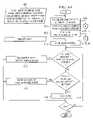
- FIGS. 2A and 2Bprovide flow charts illustrating one embodiment of a method for controlling flow of fluids to create a mixed fluid.
- the method of FIGS. 2A and 2Bcan be implemented as computer instructions that are executable by a processor stored on a computer readable medium.
- embodiments of the present inventioncan be implemented through programming of one or more OptiChem P1200 LFC flow controllers.
- FIG. 2Acorresponds to the control method implemented at the cold fluid flow controller (e.g., flow controller 104 of FIG. 1 ) and FIG. 2B corresponds to the method implemented at the hot fluid flow controller (e.g., flow controller 102 of FIG. 1 ).
- the cold fluid flow controllercan begin regulating fluid flow using Q C as a flow rate set point and issue commands the hot fluid flow controller to regulate flow of the hot fluid (step 210 ).
- the cold fluid flow controllercan adjust the flow of cold fluid according to fluid flow control schemes known in the art, including but not limited to differential control schemes, integral control schemes, proportional integral control schemes, fuzzy logic or proportional integral differential control schemes.
- cold fluid flow controllercan decrease the flow rate (step 212 ), if the fluid flow of cold water is less than the fluid flow set point, the cold fluid flow controller can increase the flow rate, and if the cold fluid flow rate equals the set point (within an acceptable system tolerance) (step 214 ), the cold fluid flow controller can maintain the flow rate (step 216 ).
- the cold fluid flow controllercan adjust the flow rate of cold fluid based on the target cold fluid flow rate set point Q C .
- the hot fluid flow controllercan adjust the flow rate of the hot fluid based on the temperature of the mixed fluid (t M1 ) and the mixed fluid set point (t SP ).
- the temperature of the mixed fluidcan be received either directly from a temperature sensor or from the cold fluid flow controller. If t M1 is greater than t SP , the hot fluid flow controller decreases the flow rate of fluid (step 218 ), if t M1 is less than t SP , the hot fluid flow controller increases the flow rate of the hot fluid (step 220 ) and if t M1 is equal to t SP (within acceptable system tolerances), the hot fluid flow controller maintains the flow rate of hot fluid (step 222 ).
- FIGS. 2A and 2Bcan be repeated as needed or desired. Moreover, the various steps can be performed in a variety of orders and various steps performed by each flow controller can be performed in parallel.
- the cold water flow controlleris responsible for determining the set point t SP for the hot water flow controller
- the hot water flow controllercan determine t SP for itself or provide t SP to the cold water flow controller so that the cold water flow controller can regulate flow based on t M .
- the roles of the hot and cold water flow controllerscan be reversed and the steps of FIG. 2 can be otherwise distributed between the controllers.
- one embodiment of the present inventioncan include a first flow controller (e.g. flow controller 104 ), a second flow controller (e.g. flow controller 102 ) and a mixer downstream of the first and second flow controllers.
- the first flow controllercan regulate the flow of a first fluid based on a target flow rate for the first fluid (e.g., Q C ), and the second flow controller can regulate the flow of a second fluid based on a temperature set point and a temperature of the mixed fluid created by the mixer.
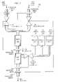
- FIG. 3illustrates a solution mixing system 300 that incorporates the subsystem of FIG. 1 .
- solution mixing system 300provides a concentrated NaCl solution mixing system in which the mixed DIW 118 is combined with NaCl to produce dilute NaCl 302 .
- solution mixing system 300includes one or more sources of concentrated NaCl (here illustrated as 1800 parts per million (ppm) NaCl source 304 , 2000 ppm source 306 and 2200 ppm source 308 ).
- a chemical flow controller 310controls the flow of concentrated NaCl to a second mixer 312 where the concentrated chemical is mixed with mixed DIW 118 .
- Mixer 312can be a static mixer.
- cold fluid flow controller 104can act as a master controller for hot fluid flow controller 102 and chemical flow controller 310 .
- Cold fluid flow controller 104receives a target mixed chemical flow rate (Q T2 ) for dilute NaCl 302 , a target mixed chemical ratio for dilute NaCl, a target mixed chemical temperature (t T2 ) for dilute NaCl 302 , t C , and t H .
- Q T2target mixed chemical flow rate
- t T2target mixed chemical temperature
- cold fluid controller 104can determine the target flow rate of DIW (Q T1 ) and flow rate of concentrated NaCl (Q chem ).
- cold fluid flow controller 104can further determine the target cold DIW flow rate (Q C ) and temperature set point t SP for hot fluid flow controller 104 .
- Cold fluid flow controller 104provides t SP to hot fluid flow controller 102 and Q chem to chemical flow controller 310 . Each flow controller can then control the flow of its respective fluid.
- FIGS. 4A-4Care flow charts illustrating one embodiment of a method for controlling flow of fluids to create a mixed fluid.
- the method of FIGS. 4A-4Ccan be implemented as computer instructions that are executable by a processor stored on a computer readable medium.
- embodiments of the present inventioncan be implemented through programming of one or more OptiChem P1200 LFC flow controllers.
- FIG. 4Acorresponds to the control method implemented at the cold fluid flow controller (e.g., flow controller 104 of FIG. 3 )
- FIG. 4Bcorresponds to the control method implemented at the hot fluid flow controller (e.g., flow controller 102 of FIG. 3 )
- FIG. 4Cto the control method implemented at chemical flow controller 310 .
- the cold fluid flow controllerreceives inputs including the target mixed chemical mix ratio, the target mixed chemical flow rate (Q T2 ), the cold fluid temperature (t C ), the hot fluid temperature (t H ), the target mixed chemical temperature (t T2 ) (step 402 ).
- the cold fluid flow controllercan determine the target DIW flow rate Q T1 and the flow rate of the concentrated chemical or other fluid (Q chem ) (e.g., NaCl in the example of FIG. 3 ) (step 406 ).
- the cold fluid flow controllercan begin regulating fluid flow using Q C as a flow rate set point, issue commands to the hot fluid flow controller to regulate flow of the hot fluid and issue commands to the chemical flow controller to control flow of the third fluid.
- the cold fluid flow controllercan for adjust the flow of cold fluid according to fluid flow control schemes known in the art, including but not limited to differential control schemes, integral control schemes, proportional integral control schemes, fuzzy logic or proportional integral differential control schemes.
- cold fluid flow controllercan decrease the flow rate (step 412 ), if the fluid flow of cold water is less than the fluid flow set point (step 414 ), the cold fluid flow controller can increase the flow rate, and if the cold fluid flow rate equals the set point (within an acceptable system tolerance), the cold fluid flow controller can maintain the flow rate (step 416 ).
- the cold fluid flow controllercan adjust the flow rate of cold fluid based on the cold fluid flow rate set point Q C .
- the hot fluid flow controllercan adjust the flow rate of the hot fluid based on the temperature of the mixed fluid (t M1 ) and the mixed fluid set point (t SP ).
- the temperature of the mixed fluidcan be received either directly from a temperature sensor or from the cold fluid flow controller. If t M1 is greater than t SP , the hot fluid flow controller decreases the flow rate of fluid (step 418 ), if t M1 is less than t SP , the hot fluid flow controller increases the flow rate of the hot fluid (step 420 ) and if t M1 is equal to t SP (within acceptable system tolerances), the hot fluid flow controller maintains the flow rate of hot fluid (step 422 ).
- the chemical flow controllercan similarly adjust the flow of the additional fluid (e.g., concentrated NaCl) based on Q chem as is shown in FIG. 4C . If the fluid flow of the concentrated chemical (or other fluid) is greater than the Q chem , chemical flow controller can decrease the flow rate (step 428 ), if the fluid flow of the concentrated chemical is less than Q chem (step 430 ), the cold fluid flow controller can increase the flow rate, and if the concentrated chemical flow rate equals the set point (within an acceptable system tolerance), the chemical flow controller can maintain the flow rate (step 434 ). Thus, the chemical flow controller can adjust the flow rate of concentrated chemical based on the cold fluid flow rate set point Q chem .
- the additional fluide.g., concentrated NaCl
- FIGS. 4A-4Crepresent one example embodiment of the present invention. However, it should be understood, that the steps of FIGS. 4A-4C can be repeated as needed or desired and can be performed in different orders. Moreover, the steps implemented at each flow controller can be performed in parallel. While, in FIGS. 4A-4C , the cold water flow controller is responsible for calculating various parameters and asserting set points to the hot water flow controller and chemical flow controller, the step of FIGS. 4A-4C can be otherwise distributed to the flow controllers. Additionally, the roles of the hot water and cold water flow controllers can be reversed such that the hot water flow controller controls flow based on a flow rate set point and the cold water flow controller controls flow based on a temperature set point.
- t T2is not greatly affected by the temperature of the additional fluid added at the second mixer 312 .
- the temperature of fluid at the outlet of mixer 312is approximately t M1 (i.e., is approximately the temperature of the mixed DIW).
- an additional temperature sensorcan be used to measure t M2 so that this temperature can be used in flow control.
- FIG. 5is a diagrammatic representation of one embodiment of a solution mixing system 500 similar to that of FIG. 3 that adds a conductivity meter 502 and an additional temperature sensor 504 downstream of second mixer 312 .
- the conductivity of a fluidis typically related to the concentration of a fluid
- the feedback from conductivity sensor 502can be used to adjust the concentration of concentrated chemical added at static mixer 312 to achieve a desired conductivity.
- the temperature read by temperature sensor 504can be used to adjust the flow rates of the hot and cold DIW.
- cold fluid flow controller 104can act as a master controller for hot fluid flow controller 102 and chemical flow controller 310 .
- cold fluid flow controller 104receives a target mixed chemical flow rate (Q T2 ), a target mixed chemical ratio, a target mixed chemical temperature (t T2 ), t C , and t H .
- target mixed chemical flow rate Q T2 and the target mixed chemical ratiocold fluid controller 104 can determine the target flow rate of DIW (Q T1 ) and flow rate of concentrated NaCl (Q chem ).
- t T1can be set equal to t T2 .
- cold fluid flow controller 104can further determine the target cold DIW flow rate (Q C ) and temperature set point t SP for hot fluid flow controller 104 .
- t SPcan also initially be set equal to t T2 .
- Cold fluid flow controller 104provides t SP to hot fluid flow controller 102 and Q chem to chemical flow controller 310 . Each flow controller can then control the flow of its respective fluid.
- controller 104can use the temperature of the dilute chemical (t M2 ) to adjust the flow rates of hot and cold DIW. Although control using t M2 can begin immediately, according to other embodiments, cold fluid flow controller 104 can wait a predefined period of time before beginning control using t M2 . This can be done, for example, to allow the flow and temperature of the dilute chemical to settle.
- Cold fluid flow controller 104can further determine a new target flow rate for the cold DIW (i.e., a new Q C ) using the t SP calculated in EQN 2 for t T of EQN 1. As described above, cold fluid flow controller 104 can regulate flow according to Q C and hot fluid flow controller 102 can regulate flow according to t SP and t M1 .
- FIGS. 6A-6Care flow charts illustrating one embodiment of a method for controlling flow of fluids to create a mixed fluid.
- the method of FIGS. 6A-6Ccan be implemented as computer instructions that are executable by a processor stored on a computer readable medium.
- embodiments of the present inventioncan be implemented through programming of one or more OptiChem P1200 LFC flow controllers.
- FIG. 6Acorresponds to the control method implemented at the cold fluid flow controller (e.g., flow controller 104 of FIG. 5 )
- FIG. 6Bcorresponds to the control method implemented at the hot fluid flow controller (e.g., flow controller 102 of FIG. 5 )
- FIG. 6Ccorresponds to the control method implemented at chemical flow controller 310 .
- the cold fluid flow controllerreceives inputs including target mixed chemical mix ratio, the target mixed chemical flow rate (Q T2 ), the cold fluid temperature (t C ), the hot fluid temperature (t H ), the target mixed chemical temperature (t T2 ) (step 602 ).
- the cold fluid flow controllercan determine the target DIW flow rate Q T1 and the f low rate of the concentrated chemical or other fluid (Q chem ) (e.g., NaCl in the example of FIG. 5 ) (step 606 ).
- Flow controller 102can initially act as if the flow of NaCl will have little effect on the temperature of t T2 .
- the cold fluid flow controllercan begin regulating fluid flow using Q C as a flow rate set point, issue commands the hot fluid flow controller to regulate flow of the hot fluid and issue commands to the chemical flow controller to control flow of the third fluid.
- the cold fluid flow controllercan for adjust the flow of cold fluid according to fluid flow control schemes known in the art, including but not limited to differential control schemes, integral control schemes, proportional integral control schemes, proportional integral differential, or fuzzy logic control schemes.
- cold fluid flow controllercan decrease the flow rate (step 616 ), if the fluid flow of cold water is less than the fluid flow set point (step 618 ), the cold fluid flow controller can increase the flow rate, and if the cold fluid flow rate equals the set point (within an acceptable system tolerance), the cold fluid flow controller can maintain the flow rate (step 620 ).
- the cold fluid flow controllercan adjust the flow rate of cold fluid based on the cold fluid flow rate set point Q C .
- the cold fluid flow controllercan also receive the temperature of the mixed chemical from a temperature sensor downstream of the second mixer (e.g., can receive t M2 from temperature sensor 504 of FIG. 5 ) (step 622 ). Using t M2 , the cold fluid flow controller can calculate a new Q C and t M2 as, for example, described in conjunction with FIG. 5 (step 638 ). Cold fluid flow controller can then perform steps 618 - 620 using the new Q C and pass the new t SP to the hot fluid flow controller. According to one embodiment, Q C and t SP can be continually updated as t M2 changes.
- the hot fluid flow controllercan adjust the flow rate of the hot fluid based on the temperature of the mixed fluid (t M1 ) and the mixed fluid set point (t SP ).
- the temperature of the mixed fluidcan be received either directly from a temperature sensor or from the cold fluid flow controller.
- Hot water flow controller 104receives the initial temperature set point t SP (step 623 ).
- the hot fluid flow controllerdecreases the flow rate of fluid (step 624 ), if t M1 is less than t SP , the hot fluid flow controller increases the flow rate of the hot fluid (step 626 ) and if t M1 is equal to t SP (within acceptable system tolerances), the hot fluid flow controller maintains the flow rate of hot fluid (step 628 ).
- the hot fluid flow controllercan receive the new temperature set point at step 629 and perform steps 624 - 628 accordingly.
- the chemical flow controllercan similarly adjust the flow of the additional fluid (e.g., concentrated NaCl) based on Q chem . If the fluid flow of the concentrated chemical (or other fluid) is greater than the Q chem , chemical flow controller can decrease the flow rate (step 630 ), if the fluid flow of the concentrated chemical is less than Q chem (step 632 ), the cold fluid flow controller can increase the flow rate, and if the concentrated chemical flow rate equals the set point (within an acceptable system tolerance), the chemical flow controller can maintain the flow rate (step 634 ). Thus, the chemical flow controller can adjust the flow rate of concentrated chemical based on the cold fluid flow rate set point Q chem .
- the additional fluide.g., concentrated NaCl
- the chemical flow controllercan receive a measurement of conductivity of the mixed chemical (step 640 ). Using the conductivity, the flow controller can adjust the concentration of chemical added at the second mixer. If the conductivity indicates that the mixed chemical is too concentrated, the flow controller can decrease the concentration of concentrated chemical (step 642 ). If the conductivity sensor indicates that the mixed chemical is too dilute, the flow controller can increase the concentration of the concentrated chemical added to the DIW. Otherwise, the concentration can be unchanged (step 646 ).
- FIGS. 6A-6Crepresent one example embodiment of the present invention. However, it should be understood, that the steps of FIGS. 6A-6C can be repeated as needed or desired and can be performed in different orders. Moreover, the steps implemented at each flow controller can be performed in parallel. While, in FIGS. 6A-6C , the cold water flow controller is responsible for calculating various parameters and asserting set points to the hot water flow controller and chemical flow controller, the steps of FIGS. 6A-6C can be otherwise distributed to the flow controllers. Additionally, the roles of the hot water and cold water flow controllers can be reversed such that the hot water flow controller controls flow based on a flow rate set point and the cold water flow controller controls flow based on a temperature set point.
- FIGS. 7A-7Fprovide diagrammatic representations of one embodiment of a static mixer assembly 700 and its components.
- static mixer assembly 700includes a mixer housing 702 , an inlet assembly 704 and an outlet assembly 706 .
- Inlet assembly 704includes two inlets, inlet 708 and inlet 710 . These inlets can be coupled to fluid supply lines that lead from upstream flow controllers.
- inlet 708can receive hot DIW from hot DIW flow controller 102
- inlet 710can receive cold DIW from cold DIW flow controller 104 .
- inlet assembly 704has male threaded sections 712 and 714 to connect to inlet supply lines.
- outlet assembly 706has male threaded section 716 to connect to an outlet line.
- FIG. 7Bis a partial cutaway of mixer assembly 700 and illustrates a flow path 718 defined through mixer housing 702 from inlet assembly 704 to outlet assembly 706 .
- fluids entering inlet 708 and inlet 710 of inlet assembly 704exit a common outlet.
- FIG. 7Bfurther illustrates that inlet assembly 704 can include a male threaded portion 719 and outlet assembly 706 can include a male threaded portion 720 to couple to mixer housing 702 , which has corresponding female threaded portions.
- FIG. 7Cillustrates another partial cutaway of mixer assembly 700 .
- mixer assembly 700includes a mixer disk 722 that acts as a static mixer.
- mixer disk 722is located in mixer housing 702 at the outlet side of inlet assembly 704 .
- Mixer disk 722can include a seating flange 724 that rests in a corresponding annular ring of housing assembly 702 .
- Seating flange 724working in concert with the annular ring as a tongue and groove fitting, can ensure proper seating of mixer disk 722 in mixer housing 702 .
- mixer disk 722can include an annular ring 726 on its upstream side that receives a flange on the outlet side of inlet assembly 704 . This also aids in proper seating of mixer disk 722 .
- inlet assembly 704 and outlet assembly 706are configured to connect to 3 ⁇ 8 inch O.D. tubing with a 0.25 inch bore and flow path 718 has a 0.21 inch diameter.
- the various components of mixer assembly 700can be machined or molded from Teflon or modified Teflon.
- FIG. 7Dis a diagrammatic representation of one embodiment of mixer disk 722 showing one embodiment of the upstream side.
- Mixer disk 722includes an outer section 728 defined by an outer surface 729 at an outer circumference and an inner surface 730 at an inner circumference 731 . Additionally, outer section 728 can include an annular ring 726 that receives, as discussed above, a flange on the outlet side of inlet assembly 704 to aid in seating.
- an inner flange 732projects inwardly from inner surface 730 with an inner flange surface 733 that defines a flow passage.
- Two radially opposed mixing tabs(tab 736 and 738 ) further project inwardly towards each other.
- mixing tab 736 and 738do not touch, but have a small gap between them to leave the center of the flow passage unobstructed.
- Mixing tab 736 and mixing tab 738can have downstream surfaces extending approximately normal to inner flange surface 733 and inclined upstream surfaces such that the mixing tabs are thinner near the center of the flow passage and wider proximate to inner flange 732 .
- the upstream surfaces of mixing tabs 736 and 738are inclined approximately fifteen degrees.
- Mixer disk 722can further include an alignment notch 740 to align mixer disk 722 in mixer assembly housing 702 .
- Alignment notch 740can mate with a corresponding protrusion in mixer assembly housing 702 to align mixer disk 722 to have a particular orientation.
- mixer disk 722can be aligned such that mixing tabs are oriented in particular direction.
- FIG. 7Eis a diagrammatic representation of mixer disk 722 from an upstream view.
- the outer diameter of outer section 728can be 0.55 inches, and the inner diameter 0.21 inches.
- the inner diameter of inner flange 732can further be 0.166 inches.
- Each of mixing tabs 736 and 738can extend inwardly 0.074 from inner flange 732 with a gap of 0.018 inches between the mixing tabs.
- annular groove 726can have an outer diameter of 0.45 inches and a thickness of 0.029 inches. It should be noted that these dimensions are provided by way of example and not limitation and larger or smaller mixing disks can be used. Additionally, the various radii or other example dimensions can be differently proportioned relative to each other.
- FIG. 7Fis a section view of one embodiment mixer disk 722 along line AA of FIG. 7E .
- FIG. 7Fillustrates seating flange 724 .
- seating flange 724is an annular ring projecting from the downstream side of mixer disk 722 .
- tabs 736 and 738can be wedge shaped with the upstream surface of each tab angling 15 degrees inward as it approaches the center of mixer disk 722 .
- the downstream surfaceremains perpendicular to the flow passage.
- the tabscan have other shapes and there can be more than two tabs, or a single tab. Additionally, the dimensions and angles shown in FIG. 7F are provided by way of example, but not limitation.
- FIGS. 8A-8Cprovide diagrammatic representations of another embodiment of a mixer assembly.
- static mixer assembly 800includes a mixer housing 802 , three inlet assemblies 804 , 806 and 808 an outlet assembly 810 .
- Each of the inlet assembliescan include an inlet connected by a supply line to supply a fluid.
- inlet assembly 804includes an inlet through which the mixed fluid (e.g., mixed DIW) can supplied (e.g., from mixer 106 of FIG. 3 ) while inlet assemblies 806 and 808 include inlets through which concentrated chemical can be provided by a chemical flow controller (e.g., chemical flow controller 310 of FIG. 3 ).
- a chemical flow controllere.g., chemical flow controller 310 of FIG. 3
- inlet assemblies 804 , 806 and 808have male threaded sections 812 , 814 and 816 , respectively, to connect to inlet supply lines.
- outlet assembly 810has male threaded section 818 to connect to an outlet line.
- FIG. 8Bis a partial cutaway of mixer assembly 800 and illustrates a flow path 820 defined through mixer housing 802 from inlet assembly 804 to outlet assembly 810 . Additionally, FIG. 8B illustrates fluid flow paths 822 and 824 through inlet assemblies 806 and 808 , respectively, which join with flow path 820 . Thus, fluids entering inlet assembly 804 , inlet assembly 806 and inlet assembly 808 exit a common outlet.
- FIG. 8Bis a partial cutaway of mixer assembly 800 and illustrates a flow path 820 defined through mixer housing 802 from inlet assembly 804 to outlet assembly 810 . Additionally, FIG. 8B illustrates fluid flow paths 822 and 824 through inlet assemblies 806 and 808 , respectively, which join with flow path 820 . Thus, fluids entering inlet assembly 804 , inlet assembly 806 and inlet assembly 808 exit a common outlet.
- inlet assembly 804can include male threaded portion 824
- inlet assembly 806can include male threaded portion 826
- inlet assembly 808includes male threaded portion 828
- outlet assembly 810can include a male threaded portion 830 to couple to mixer housing 802 , which has corresponding female threaded portions.
- FIG. 8Cillustrates a cross sectional view of one embodiment of mixer assembly 800 .
- mixer assembly 800includes a mixer disk 832 that acts as a static mixer.
- mixer disk 832is located in mixer housing 802 at the outlet side of inlet assembly 804 .
- Mixer disk 832can include a seating flange 834 that rests in a corresponding annular ring of housing assembly 802 .
- Seating flange 834working in concert with the annular ring as a tongue and groove fitting, can ensure proper seating of mixer disk 832 in mixer housing 802 .
- mixer disk 832can include an annular ring 836 that receives a flange on the outlet side of inlet assembly 804 . This also aids in proper seating of mixer disk 832 .
- FIG. 8Calso illustrates that flow passages 822 and 824 intersect with flow passage 820 downstream of mixer disk 832 . Consequently, in a mixing system such as that depicted in FIG. 3 , the concentrated chemical is introduced downstream of mixing disk 822 .
- inlet assembly 804 , inlet assembly 806 , inlet assembly 808 and outlet assembly 810are configured to connect to 3 ⁇ 8 inch O.D. tubing with a 0.25 inch bore.
- flow path 218has a 0.21 inch diameter.
- the various components of mixer assembly 800can be machined or molded from Teflon or modified Teflon.
- Mixer disk 822can be similar or identical to mixer disk 722 of FIGS. 7D-7F .
- Mixing disk 822can be aligned (e.g. using the alignment notch) such that the tabs of mixing disk 822 are aligned over flow passage 822 and flow passage 824 .
- embodiments of the present inventioncan provide a fluid mixing system that utilizes various flow controllers (e.g., hot DIW controller 102 , cold DIW controller 104 and chemical flow controller 310 ).
- various flow controllerse.g., hot DIW controller 102 , cold DIW controller 104 and chemical flow controller 310 .
- one of the flow controllerscan act as a master controller that communicates set points to the other flow controllers.
- the master flow controlleris preferably capable of asserting multiple set points.
- Embodiments of the present inventionreduce or eliminate the deficiencies associated with having a limited number of analog ports by providing for multiplexing of analog set points on a particular analog communications link.
- FIG. 9is a diagrammatic representation of one embodiment of a system 900 for multiplexing analog set points.
- System 900includes an analog signal source 902 connected to multiple slave devices 904 a - 904 d via an analog communications link 906 and one or more parallel digital communications links 908 .
- Analog signal source 902can be a flow controller, such as an OptiChem P1200 produced by Mykrolis, Inc. of Billerica, Mass. (now part of Entegris Corporation of Chaska, Minn.).
- devices 904 a - 904 dcan also be OptiChem P1200 flow controllers.
- one flow controller, acting as analog signal source 902can act as a master device to other flow controllers.
- analog signal source 902can be any device capable of asserting an analog set point and devices 904 a - 904 d can be any devices capable of receiving analog set points.
- Analog signal source 902outputs an analog signal including set points for multiple slave devices on analog communications link 906 .
- Digital communications links 908 a - 908 dcan carry set point indicator signals to each of slave devices 904 a - 904 d . It should be noted that the digital communications links can be separate busses or the same bus arbitrated to send a digital signal to a particular slave device 904 .
- a set point indicator signal for a particular slave deviceindicates that the analog signal is indicating the set point for that slave device.
- the particular slave device 904can read its set point from the analog signal.
- Using the set point indicator signals to indicate when set points for particular devices are being asserted on an analog lineallows multiple analog set points to be multiplexed on a single analog bus 906 .
- analog set point signal and set point indicator signalsare illustrated as coming from the same master device. However, in other embodiments of the present invention, the analog set point signal and set point indicator signals can be generated at distributed devices.
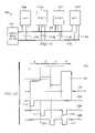
- FIG. 10illustrates one embodiment of a an analog set point signal 1000 asserted by analog signal source 902 , a set point indicator 1002 signal for slave device 904 a a set point indicator signal 1004 for slave device 904 b , a set point indicator signal 1006 for slave device 904 c and a set point indicator signal 1008 for slave device 904 d .
- analog set point signal 1000can have voltages/current between 0% and 100% of a full scale value, whereas the set point indicator signals are either high or low (e.g., cycling between +/ ⁇ 3.3 volts or other voltage values or other values indicating a setpoint).
- analog set pointsare multiplexed into analog signal 1000 .
- the set pointis 45% of full scale; for time period t 2 , the set point is 62% of full scale; for time period t 3 , the set point is 30% of full scale; and for time period t 4 , the set point is 78% of full scale.
- the analog set point valuesmay have different meanings for the various slave devices.
- the analog set pointmay correspond to a pressure at slave device 904 a , but a pump motor speed at slave device 904 b .
- the analog set point signalcan multiplex analog set points for a variety of purposes.
- set point indicator signal 1002changes states from high to low (shown at 1010 ) indicating that slave device 904 a should use the 45% of full scale value as its set point. Slave device 904 a can continue to use this set point value until the set point indicator signal indicates that it should read a new set point from the analog set point signal 1000 . Thus, slave device 904 a can continue to use the 45% of full scale set point even though the value of the analog signal is changing.
- set point indicator signal 1004indicates that slave device 904 b should use the 62% of full scale as its set point (shown at 1012 )
- set point indicator signal 1006indicates that slave device 904 c should use the 30% of full scale as its set point (shown at 1014 )
- set point indicator signal 1008indicates that slave device 904 d should use the 78% of full scale as its set point (shown at 1016 ).
- the signal timings provided in FIG. 10are provided by way of example and any suitable scheme for indicating to a slave device when the analog signal is carrying the set point for that device can be utilized.
- the set point indicator signalcan change states (e.g., from low to high, from high to low or undergo other state change) when the slave device should begin reading its set point from the analog set point signal and change states again when the slave device should stop reading its set point from the analog set point signal.
- the set point indicatorcan be sent to the slave devices in a variety of manners, including as part of a data stream, an interrupt or in another manner.
- FIG. 11is a diagrammatic representation of one embodiment of a system 1100 for multiplexing analog set points.
- System 1100includes an analog signal source 1102 connected to multiple slave devices 1104 a - 1104 d via an analog communications link 1106 and a digital bus 1107 .
- Digital bus 1107is connected to slave devices 1104 a - 1104 d at 1108 a - 1108 d respectively.
- Digital bus 1107can include any number of lines for carrying signals to slave devices 1104 a - 1104 d . In the example of FIG. 11 , digital bus has three signaling lines.
- Analog signal source 1102can be a flow controller, such as an OptiChem P1200 produced by Mykrolis, Inc. of Billerica, Mass. (now part of Entegris Corporation of Chaska, Minn.).
- devices 1104 a - 1104 dcan also be OptiChem P1200 flow controllers.
- one flow controller, acting as analog signal source 1102can act as a master device to other flow controllers.
- analog signal source 1102can be any device capable of asserting an analog set point and devices 1104 a - 1104 d can be any devices capable of receiving analog set points.
- Analog signal source 1102outputs an analog signal including set points for multiple slave devices on analog communications link 1106 .
- Digital bus 1107can carry set point indicator signals to each of slave devices 1104 a - 1104 d .
- a set point indicator signal for a particular slave deviceindicates that the analog signal is indicating the set point for that slave device.
- the set point indicator signal for a particular slave device 1104can be asserted as multiple bits on bus 1107 .
- the set point indicator for slave device 1104 dcan be bits asserted on the second and third signaling lines of bus 1107 (e.g., 011).
- the particular slave device 1104can read its set point from the analog signal.
- Implementing a binary weighted system for each of the digital select lineextends the capabilities of the master without increasing the number of digital setpoint indicator lines.
- analog set point signal and set point indicator signalsare illustrated as coming from the same master device. However, in other embodiments of the present invention, the analog set point signal and set point indicator signals can be generated at distributed devices.
- FIG. 12illustrates one embodiment of a an analog set point signal 1200 asserted by analog signal source 1102 , and digital signals for providing setpoint indicators.
- analog set point signal 1200can have voltages/current between 0% and 100% of a full scale value, whereas the set point indicator signals are either high or low (e.g., cycling between +/ ⁇ 3.3 volts or other voltage values or other values indicating a setpoint).
- analog set pointsare multiplexed into analog signal 1300 .
- the set pointis 45% of full scale; for time period t 2 , the set point is 62% of full scale; for time period t 3 , the set point is 30% of full scale; and for time period t 4 , the set point is 78% of full scale.
- the analog set point valuesmay have different meanings for the various slave devices.
- the analog set pointmay correspond to a pressure at slave device 1104 a , but a pump motor speed at slave device 1104 b .
- the analog set point signalcan multiplex analog set points for a variety of purposes.
- set point signal 1202changes states from high to low (shown at 1210 ) indicating that slave device 1104 a should use the 45% of full scale value as its set point.
- Slave device 1104 acan continue to use this set point value until the set point indicator signal indicates that it should read a new set point from the analog set point signal 1200 .
- slave device 1104 acan continue to use the 45% of full scale set point even though the value of the analog signal is changing.
- signal 1204indicates that slave device 1104 b should use the 62% of full scale as its set point (shown at 1212 )
- signal 1206indicates that slave device 1104 c should use the 30% of full scale as its set point (shown at 1314 ).
- signals 1204 and 1206assert a bit (shown at 1216 and 1218 ), indicating that slave device 1104 d should use the 78% of full scale as its set point (i.e., multiple digital lines are used to send the setpoint indicator to slave device 1104 d ).
- three set point indicator linesare used to indicate setpoint to four slave devices.
- Using a binary scheme up to 7 slave devicescan be supported (2 n ⁇ 1, where n is the number of setpoint indicator lines) with one signal state reserved for the case in which no setpoint is being asserted for a device.
- the signal timings provided in FIG. 12are provided by way of example and any suitable scheme for indicating to a slave device when the analog signal is carrying the set point for that device can be utilized.
- the set point indicator signalcan change states (e.g., from low to high, from high to low or undergo other state change) when the slave device should begin reading its set point from the analog set point signal and change states again when the slave device should stop reading its set point from the analog set point signal.
- the set point indicatorcan be sent to the slave devices in a variety of manners, including as part of a data stream, an interrupt or in another manner.
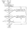
- FIG. 13is a flow chart illustrating one embodiment of a method for multiplexing analog set points.
- the flow chartis divided into two sections for the master and slave device.
- the methodology of FIG. 13can be implemented, for example, by execution of computer instructions at the master, slave or other devices.
- an analog signal sourcegenerates an analog signal representing multiple set points (step 1302 ). Put another way, multiple analog set points are multiplexed in the analog signal.
- the master devicecommunicates the analog signal to the slave devices. When the set point for a particular slave device is being transmitted via the analog signal, the master device can send a set point indicator to that slave device (step 1304 ). For example, the master device can use a signal on a digital bus (e.g., by changing the state of a line or lines on the bus) to indicate to a particular slave device that its set point is being asserted on the analog line.
- the routinecan continue until a predefined event occurs to end the routine.
- the slave devicecan receive the analog set point signal (step 1306 ).
- the slave devicecan save the value of the analog set point signal and store the signal as its set point (step 1310 ). This routine can continue until a predefined event occurs to end the routine. Additionally, the steps of FIG. 13 can be repeated as needed or desired.
Landscapes
- Chemical & Material Sciences (AREA)
- Chemical Kinetics & Catalysis (AREA)
- Physics & Mathematics (AREA)
- General Physics & Mathematics (AREA)
- Engineering & Computer Science (AREA)
- Automation & Control Theory (AREA)
- Accessories For Mixers (AREA)
Abstract
Description
| TABLE 1 | ||
| Order | ρ = f (t) | Cp = f (t) |
| 0 | .99988 | 1.00919 |
| 1 | 6.20242E−05 | −9.50319E−04 |
| 2 | −8.37727E−06 | 2.8655E−05 |
| 3 | 6.62195E−08 | −4.28993E−07 |
| 4 | −4.17404E−10 | 3.44932E−09 |
| 5 | 1.15955E−12 | −1.10643E−11 |
QC=QT*(1000/60)*(ρC/ρT)*(tH*CpH−tTCpT)/(tH*CpH−tC*CpC) [EQN. 1]
| QT= target flow rate | (lpm) | ||
| tT= target temperature | (° C.) | ||
| tH= hot fluid temperature | (° C.) | ||
| tC= cold fluid temperature | (° C.) | ||
| ρC= cold fluid density | (g/cm3) | ||
| ρH= hot fluid density | (g/cm3) | ||
| CpC= cold fluid specific heat | (cal/g * ° C.) | ||
| CpH= hot fluid specific heat | (cal/g * ° C.) | ||
| CpT= mixed fluid specific heat at tT | (cal/g * ° C.) | ||
Continuing with the previous example, QT=QT1and tT=tT1, and flow
tSP(n)=tSP(n−1)+(tT2−tM2) [EQN. 2]
Claims (15)
Priority Applications (11)
| Application Number | Priority Date | Filing Date | Title |
|---|---|---|---|
| US11/365,395US7684446B2 (en) | 2006-03-01 | 2006-03-01 | System and method for multiplexing setpoints |
| US11/386,427US7494265B2 (en) | 2006-03-01 | 2006-03-22 | System and method for controlled mixing of fluids via temperature |
| TW096106720ATW200741398A (en) | 2006-03-01 | 2007-02-27 | System and method for controlled mixing of fluids and multiplexing setpoints |
| CNA2007800154686ACN101573174A (en) | 2006-03-01 | 2007-02-28 | System and method for controlling fluid mixing and multiplexing set points |
| JP2008557400AJP2009528631A (en) | 2006-03-01 | 2007-02-28 | System and method for controlled fluid mixing and setpoint multiplexing |
| EP07752100AEP1991347A4 (en) | 2006-03-01 | 2007-02-28 | System and method for controlled mixing of fluids and multiplexing setpoints |
| CN2011101961727ACN102339078A (en) | 2006-03-01 | 2007-02-28 | System and method for controlled mixing of fluids and multiplexing setpoints |
| KR1020087023991AKR20080100379A (en) | 2006-03-01 | 2007-02-28 | Apparatus and method for controlled mixing of fluids and multiplexing set points |
| PCT/US2007/005377WO2007103184A2 (en) | 2006-03-01 | 2007-02-28 | System and method for controlled mixing of fluids and multiplexing setpoints |
| US12/350,688US7946751B2 (en) | 2006-03-01 | 2009-01-08 | Method for controlled mixing of fluids via temperature |
| US13/092,581US20110194373A1 (en) | 2006-03-01 | 2011-04-22 | Method for controlled mixing of fluids via temperature |
Applications Claiming Priority (1)
| Application Number | Priority Date | Filing Date | Title |
|---|---|---|---|
| US11/365,395US7684446B2 (en) | 2006-03-01 | 2006-03-01 | System and method for multiplexing setpoints |
Related Child Applications (1)
| Application Number | Title | Priority Date | Filing Date |
|---|---|---|---|
| US11/386,427DivisionUS7494265B2 (en) | 2006-03-01 | 2006-03-22 | System and method for controlled mixing of fluids via temperature |
Publications (2)
| Publication Number | Publication Date |
|---|---|
| US20070217442A1 US20070217442A1 (en) | 2007-09-20 |
| US7684446B2true US7684446B2 (en) | 2010-03-23 |
Family
ID=38471313
Family Applications (1)
| Application Number | Title | Priority Date | Filing Date |
|---|---|---|---|
| US11/365,395Expired - Fee RelatedUS7684446B2 (en) | 2006-03-01 | 2006-03-01 | System and method for multiplexing setpoints |
Country Status (3)
| Country | Link |
|---|---|
| US (1) | US7684446B2 (en) |
| CN (1) | CN101573174A (en) |
| TW (1) | TW200741398A (en) |
Cited By (14)
| Publication number | Priority date | Publication date | Assignee | Title |
|---|---|---|---|---|
| US20070104586A1 (en)* | 1998-11-23 | 2007-05-10 | James Cedrone | System and method for correcting for pressure variations using a motor |
| US20070128047A1 (en)* | 2005-12-02 | 2007-06-07 | George Gonnella | System and method for monitoring operation of a pump |
| US20070128050A1 (en)* | 2005-11-21 | 2007-06-07 | James Cedrone | System and method for a pump with reduced form factor |
| US20070125796A1 (en)* | 2005-12-05 | 2007-06-07 | James Cedrone | Error volume system and method for a pump |
| US20070128048A1 (en)* | 2005-12-02 | 2007-06-07 | George Gonnella | System and method for position control of a mechanical piston in a pump |
| US20070128046A1 (en)* | 2005-12-02 | 2007-06-07 | George Gonnella | System and method for control of fluid pressure |
| US20070125797A1 (en)* | 2005-12-02 | 2007-06-07 | James Cedrone | System and method for pressure compensation in a pump |
| US20080131290A1 (en)* | 2006-11-30 | 2008-06-05 | Entegris, Inc. | System and method for operation of a pump |
| US20090047143A1 (en)* | 2005-11-21 | 2009-02-19 | Entegris, Inc. | Method and system for high viscosity pump |
| US20090116334A1 (en)* | 2006-03-01 | 2009-05-07 | Entegris, Inc. | Method for controlled mixing of fluids via temperature |
| US20090132094A1 (en)* | 2004-11-23 | 2009-05-21 | Entegris, Inc. | System and Method for a Variable Home Position Dispense System |
| US20100262304A1 (en)* | 2005-12-02 | 2010-10-14 | George Gonnella | System and method for valve sequencing in a pump |
| US20180128688A1 (en)* | 2012-07-25 | 2018-05-10 | Nxstage Medical, Inc. | Fluid Property Measurement Devices, Methods, and Systems |
| US20230266066A1 (en)* | 2022-02-21 | 2023-08-24 | Samsung Electronics Co., Ltd. | Fluid supply system |
Families Citing this family (5)
| Publication number | Priority date | Publication date | Assignee | Title |
|---|---|---|---|---|
| EP1958039B9 (en) | 2005-12-02 | 2011-09-07 | Entegris, Inc. | I/o systems, methods and devices for interfacing a pump controller |
| CN102407083A (en)* | 2010-09-25 | 2012-04-11 | 台湾关东化学股份有限公司新竹分公司 | Chemical supply system and method |
| CN104950932B (en)* | 2015-06-10 | 2017-07-28 | 广东顺德中山大学卡内基梅隆大学国际联合研究院 | The method kept based on dynamic (dynamical) agitator tank emptying and slurries output concentration |
| US10355917B2 (en)* | 2017-03-29 | 2019-07-16 | Hamilton Sundstrand Corporation | Method and apparatus for communication between master and slave processors |
| CN119536397A (en)* | 2023-08-30 | 2025-02-28 | 盛美半导体设备(上海)股份有限公司 | Solution temperature real-time control system and method |
Citations (130)
| Publication number | Priority date | Publication date | Assignee | Title |
|---|---|---|---|---|
| US269626A (en) | 1882-12-26 | brauee | ||
| US826018A (en) | 1904-11-21 | 1906-07-17 | Isaac Robert Concoff | Hose-coupling. |
| US1664125A (en) | 1926-11-10 | 1928-03-27 | John R Lowrey | Hose coupling |
| US2153664A (en) | 1937-03-08 | 1939-04-11 | Dayton Rubber Mfg Co | Strainer |
| US2215505A (en) | 1938-06-13 | 1940-09-24 | Byron Jackson Co | Variable capacity pumping apparatus |
| US2328468A (en) | 1940-12-07 | 1943-08-31 | Laffly Edmond Gabriel | Coupling device for the assembly of tubular elements |
| US2457384A (en) | 1947-02-17 | 1948-12-28 | Ace Glass Inc | Clamp for spherical joints |
| GB661522A (en) | 1949-03-31 | 1951-11-21 | Eureka Williams Corp | Improvements in or relating to oil burners |
| US2631538A (en) | 1949-11-17 | 1953-03-17 | Wilford C Thompson | Diaphragm pump |
| US2673522A (en) | 1951-04-10 | 1954-03-30 | Bendix Aviat Corp | Diaphragm pump |
| US2757966A (en) | 1952-11-06 | 1956-08-07 | Samiran David | Pipe coupling |
| US3072058A (en) | 1961-08-18 | 1963-01-08 | Socony Mobil Oil Co Inc | Pipe line control system |
| US3227279A (en) | 1963-05-06 | 1966-01-04 | Conair | Hydraulic power unit |
| US3327635A (en) | 1965-12-01 | 1967-06-27 | Texsteam Corp | Pumps |
| US3623661A (en) | 1969-02-28 | 1971-11-30 | Josef Wagner | Feed arrangement for spray painting |
| US3741298A (en) | 1971-05-17 | 1973-06-26 | L Canton | Multiple well pump assembly |
| US3895748A (en) | 1974-04-03 | 1975-07-22 | George R Klingenberg | No drip suck back units for glue or other liquids either separately installed with or incorporated into no drip suck back liquid applying and control apparatus |
| US3954352A (en) | 1972-11-13 | 1976-05-04 | Toyota Jidosha Kogyo Kabushiki Kaisha | Diaphragm vacuum pump |
| US4023592A (en) | 1976-03-17 | 1977-05-17 | Addressograph Multigraph Corporation | Pump and metering device |
| US4093403A (en) | 1976-09-15 | 1978-06-06 | Outboard Marine Corporation | Multistage fluid-actuated diaphragm pump with amplified suction capability |
| US4452265A (en) | 1979-12-27 | 1984-06-05 | Loennebring Arne | Method and apparatus for mixing liquids |
| US4483665A (en) | 1982-01-19 | 1984-11-20 | Tritec Industries, Inc. | Bellows-type pump and metering system |
| US4541455A (en) | 1983-12-12 | 1985-09-17 | Tritec Industries, Inc. | Automatic vent valve |
| US4597719A (en) | 1983-03-28 | 1986-07-01 | Canon Kabushiki Kaisha | Suck-back pump |
| US4597721A (en) | 1985-10-04 | 1986-07-01 | Valco Cincinnati, Inc. | Double acting diaphragm pump with improved disassembly means |
| US4601409A (en) | 1984-11-19 | 1986-07-22 | Tritec Industries, Inc. | Liquid chemical dispensing system |
| US4614438A (en) | 1984-04-24 | 1986-09-30 | Kabushiki Kaisha Kokusai Technicals | Method of mixing fuel oils |
| US4671545A (en) | 1985-01-29 | 1987-06-09 | Toyoda Gosei Co., Ltd. | Female-type coupling nipple |
| US4690621A (en) | 1986-04-15 | 1987-09-01 | Advanced Control Engineering | Filter pump head assembly |
| US4705461A (en) | 1979-09-19 | 1987-11-10 | Seeger Corporation | Two-component metering pump |
| US4808077A (en) | 1987-01-09 | 1989-02-28 | Hitachi, Ltd. | Pulsationless duplex plunger pump and control method thereof |
| US4821997A (en) | 1986-09-24 | 1989-04-18 | The Board Of Trustees Of The Leland Stanford Junior University | Integrated, microminiature electric-to-fluidic valve and pressure/flow regulator |
| US4824073A (en) | 1986-09-24 | 1989-04-25 | Stanford University | Integrated, microminiature electric to fluidic valve |
| US4865525A (en) | 1986-09-19 | 1989-09-12 | Grunbeck Wasseraufbereitung Gmbh | Metering pump |
| US4915126A (en) | 1986-01-20 | 1990-04-10 | Dominator Maskin Ab | Method and arrangement for changing the pressure in pneumatic or hydraulic systems |
| US4943032A (en) | 1986-09-24 | 1990-07-24 | Stanford University | Integrated, microminiature electric to fluidic valve and pressure/flow regulator |
| US4950134A (en) | 1988-12-27 | 1990-08-21 | Cybor Corporation | Precision liquid dispenser |
| US4952386A (en) | 1988-05-20 | 1990-08-28 | Athens Corporation | Method and apparatus for purifying hydrogen fluoride |
| US4966646A (en) | 1986-09-24 | 1990-10-30 | Board Of Trustees Of Leland Stanford University | Method of making an integrated, microminiature electric-to-fluidic valve |
| US5061574A (en) | 1989-11-28 | 1991-10-29 | Battelle Memorial Institute | Thick, low-stress films, and coated substrates formed therefrom |
| US5061156A (en) | 1990-05-18 | 1991-10-29 | Tritec Industries, Inc. | Bellows-type dispensing pump |
| US5062770A (en) | 1989-08-11 | 1991-11-05 | Systems Chemistry, Inc. | Fluid pumping apparatus and system with leak detection and containment |
| US5134962A (en) | 1989-09-29 | 1992-08-04 | Hitachi, Ltd. | Spin coating apparatus |
| US5135031A (en) | 1989-09-25 | 1992-08-04 | Vickers, Incorporated | Power transmission |
| US5167837A (en) | 1989-03-28 | 1992-12-01 | Fas-Technologies, Inc. | Filtering and dispensing system with independently activated pumps in series |
| US5192198A (en) | 1989-08-31 | 1993-03-09 | J. Wagner Gmbh | Diaphragm pump construction |
| US5261442A (en) | 1992-11-04 | 1993-11-16 | Bunnell Plastics, Inc. | Diaphragm valve with leak detection |
| US5262068A (en) | 1991-05-17 | 1993-11-16 | Millipore Corporation | Integrated system for filtering and dispensing fluid having fill, dispense and bubble purge strokes |
| US5316181A (en) | 1990-01-29 | 1994-05-31 | Integrated Designs, Inc. | Liquid dispensing system |
| US5344195A (en) | 1992-07-29 | 1994-09-06 | General Electric Company | Biased fluid coupling |
| US5350200A (en) | 1994-01-10 | 1994-09-27 | General Electric Company | Tube coupling assembly |
| US5380019A (en) | 1992-07-01 | 1995-01-10 | Furon Company | Spring seal |
| US5434774A (en) | 1994-03-02 | 1995-07-18 | Fisher Controls International, Inc. | Interface apparatus for two-wire communication in process control loops |
| US5476004A (en) | 1994-05-27 | 1995-12-19 | Furon Company | Leak-sensing apparatus |
| US5490765A (en) | 1993-05-17 | 1996-02-13 | Cybor Corporation | Dual stage pump system with pre-stressed diaphragms and reservoir |
| US5511797A (en) | 1993-07-28 | 1996-04-30 | Furon Company | Tandem seal gasket assembly |
| US5527161A (en) | 1992-02-13 | 1996-06-18 | Cybor Corporation | Filtering and dispensing system |
| US5546009A (en) | 1994-10-12 | 1996-08-13 | Raphael; Ian P. | Detector system using extremely low power to sense the presence or absence of an inert or hazardous fuild |
| US5575311A (en) | 1995-01-13 | 1996-11-19 | Furon Company | Three-way poppet valve apparatus |
| US5580103A (en) | 1994-07-19 | 1996-12-03 | Furon Company | Coupling device |
| US5599394A (en) | 1993-10-07 | 1997-02-04 | Dainippon Screen Mfg., Co., Ltd. | Apparatus for delivering a silica film forming solution |
| US5599100A (en) | 1994-10-07 | 1997-02-04 | Mobil Oil Corporation | Multi-phase fluids for a hydraulic system |
| US5645301A (en) | 1995-11-13 | 1997-07-08 | Furon Company | Fluid transport coupling |
| US5652391A (en) | 1995-05-12 | 1997-07-29 | Furon Company | Double-diaphragm gauge protector |
| US5653251A (en) | 1995-03-06 | 1997-08-05 | Reseal International Limited Partnership | Vacuum actuated sheath valve |
| US5743293A (en) | 1994-06-24 | 1998-04-28 | Robertshaw Controls Company | Fuel control device and methods of making the same |
| US5784573A (en) | 1994-11-04 | 1998-07-21 | Texas Instruments Incorporated | Multi-protocol local area network controller |
| US5785508A (en) | 1994-04-13 | 1998-07-28 | Knf Flodos Ag | Pump with reduced clamping pressure effect on flap valve |
| US5793754A (en)* | 1996-03-29 | 1998-08-11 | Eurotherm Controls, Inc. | Two-way, two-wire analog/digital communication system |
| EP0863538A2 (en) | 1997-03-03 | 1998-09-09 | Tokyo Electron Limited | Coating apparatus and coating method |
| EP0867649A2 (en) | 1997-03-25 | 1998-09-30 | SMC Kabushiki Kaisha | Suck back valve |
| US5839828A (en) | 1996-05-20 | 1998-11-24 | Glanville; Robert W. | Static mixer |
| US5848605A (en) | 1997-11-12 | 1998-12-15 | Cybor Corporation | Check valve |
| EP0892204A2 (en) | 1997-07-14 | 1999-01-20 | Furon Company | Improved diaphragm valve with leak detection |
| DE29909100U1 (en) | 1999-05-25 | 1999-08-12 | ARGE Meibes/Pleuger, 30916 Isernhagen | Pipe arrangement with filter |
| US5947702A (en) | 1996-12-20 | 1999-09-07 | Beco Manufacturing | High precision fluid pump with separating diaphragm and gaseous purging means on both sides of the diaphragm |
| US5971723A (en) | 1995-07-13 | 1999-10-26 | Knf Flodos Ag | Dosing pump |
| US5991279A (en)* | 1995-12-07 | 1999-11-23 | Vistar Telecommunications Inc. | Wireless packet data distributed communications system |
| WO1999066415A1 (en) | 1998-06-19 | 1999-12-23 | Gateway | Communication system and method for interfacing differing communication standards |
| US6033302A (en)* | 1997-11-07 | 2000-03-07 | Siemens Building Technologies, Inc. | Room pressure control apparatus having feedforward and feedback control and method |
| WO2000031416A1 (en) | 1998-11-23 | 2000-06-02 | Millipore Corporation | Pump controller for precision pumping apparatus |
| US6190565B1 (en) | 1993-05-17 | 2001-02-20 | David C. Bailey | Dual stage pump system with pre-stressed diaphragms and reservoir |
| US6238576B1 (en) | 1998-10-13 | 2001-05-29 | Koganei Corporation | Chemical liquid supply method and apparatus thereof |
| US6250502B1 (en) | 1999-09-20 | 2001-06-26 | Daniel A. Cote | Precision dispensing pump and method of dispensing |
| US6302660B1 (en) | 1999-10-28 | 2001-10-16 | Iwaki Co., Ltd | Tube pump with flexible tube diaphragm |
| US6318971B1 (en) | 1999-03-18 | 2001-11-20 | Kabushiki Kaisha Toyoda Jidoshokki Seisakusho | Variable displacement compressor |
| US6325032B1 (en) | 1999-09-29 | 2001-12-04 | Mitsubishi Denki Kabushiki Kaisha | Valve timing regulation device |
| US6325932B1 (en) | 1999-11-30 | 2001-12-04 | Mykrolis Corporation | Apparatus and method for pumping high viscosity fluid |
| US6330517B1 (en) | 1999-09-17 | 2001-12-11 | Rosemount Inc. | Interface for managing process |
| US6348124B1 (en) | 1999-12-14 | 2002-02-19 | Applied Materials, Inc. | Delivery of polishing agents in a wafer processing system |
| US20020044536A1 (en)* | 1997-01-14 | 2002-04-18 | Michihiro Izumi | Wireless communication system having network controller and wireless communication device connected to digital communication line, and method of controlling said system |
| US20020095240A1 (en) | 2000-11-17 | 2002-07-18 | Anselm Sickinger | Method and device for separating samples from a liquid |
| US6474950B1 (en) | 2000-07-13 | 2002-11-05 | Ingersoll-Rand Company | Oil free dry screw compressor including variable speed drive |
| US6478547B1 (en) | 1999-10-18 | 2002-11-12 | Integrated Designs L.P. | Method and apparatus for dispensing fluids |
| WO2002090771A2 (en) | 2001-05-09 | 2002-11-14 | The Provost Fellows And Scholars Of The College Of The Holy And Undivided Trinity Of Queen Elizabeth Near Dublin | A liquid pumping system |
| US6506030B1 (en) | 1999-01-05 | 2003-01-14 | Air Products And Chemicals, Inc. | Reciprocating pumps with linear motor driver |
| US20030033052A1 (en) | 2001-08-09 | 2003-02-13 | Hillen Edward Dennis | Welding system and methodology providing multiplexed cell control interface |
| US20030040881A1 (en) | 2001-08-14 | 2003-02-27 | Perry Steger | Measurement system including a programmable hardware element and measurement modules that convey interface information |
| US6540265B2 (en) | 2000-12-28 | 2003-04-01 | R. W. Beckett Corporation | Fluid fitting |
| US6554579B2 (en) | 2001-03-29 | 2003-04-29 | Integrated Designs, L.P. | Liquid dispensing system with enhanced filter |
| US6592825B2 (en) | 1996-05-31 | 2003-07-15 | Packard Instrument Company, Inc. | Microvolume liquid handling system |
| US20030148759A1 (en)* | 2002-02-01 | 2003-08-07 | Sendo International Limited | Enabling and/or Inhibiting an Operation of a Wireless Communication Unit |
| US20030222798A1 (en) | 2002-06-03 | 2003-12-04 | Visteon Global Technologies, Inc. | Method for initializing position with an encoder |
| US20040072450A1 (en) | 2002-10-15 | 2004-04-15 | Collins Jimmy D. | Spin-coating methods and apparatuses for spin-coating, including pressure sensor |
| US6742992B2 (en) | 1988-05-17 | 2004-06-01 | I-Flow Corporation | Infusion device with disposable elements |
| US20040133728A1 (en)* | 2000-12-08 | 2004-07-08 | The Boeing Company | Network device interface for digitally interfacing data channels to a controller a via network |
| US6767877B2 (en) | 2001-04-06 | 2004-07-27 | Akrion, Llc | Method and system for chemical injection in silicon wafer processing |
| US6837484B2 (en) | 2002-07-10 | 2005-01-04 | Saint-Gobain Performance Plastics, Inc. | Anti-pumping dispense valve |
| US20050061722A1 (en) | 2003-09-18 | 2005-03-24 | Kunihiko Takao | Pump, pump for liquid chromatography, and liquid chromatography apparatus |
| US20050113941A1 (en) | 1998-04-27 | 2005-05-26 | Digital Electronics Corporation | Control system, display device, control-use host computer, and data transmission method |
| US6901791B1 (en) | 1999-10-19 | 2005-06-07 | Robert Bosch Gmbh | Method and device for diagnosing of a fuel supply system |
| US20050126985A1 (en) | 1996-07-12 | 2005-06-16 | Mykrolis Corporation | Connector apparatus and system including connector apparatus |
| US6925072B1 (en)* | 2000-08-03 | 2005-08-02 | Ericsson Inc. | System and method for transmitting control information between a control unit and at least one sub-unit |
| US20050182497A1 (en) | 2004-02-18 | 2005-08-18 | Mitsubishi Denki Kabushiki Kaisha | Manufacturing system, gateway device, and computer product |
| US20050184087A1 (en) | 1998-11-23 | 2005-08-25 | Zagars Raymond A. | Pump controller for precision pumping apparatus |
| US20050197722A1 (en) | 2001-12-17 | 2005-09-08 | Varone John J. | Remote display module |
| US6952618B2 (en) | 2000-10-05 | 2005-10-04 | Karl A Daulin | Input/output control systems and methods having a plurality of master and slave controllers |
| US20050232296A1 (en)* | 2004-03-24 | 2005-10-20 | Stephan Schultze | Method for data transmission |
| US20050238497A1 (en) | 1999-12-17 | 2005-10-27 | Holst Peter A | Methods for compensating for pressure differences across valves in IV pumps |
| US20060015294A1 (en) | 2004-07-07 | 2006-01-19 | Yetter Forrest G Jr | Data collection and analysis system |
| US7013223B1 (en) | 2002-09-25 | 2006-03-14 | The Board Of Trustees Of The University Of Illinois | Method and apparatus for analyzing performance of a hydraulic pump |
| US20060083259A1 (en)* | 2004-10-18 | 2006-04-20 | Metcalf Thomas D | Packet-based systems and methods for distributing data |
| WO2006057957A2 (en) | 2004-11-23 | 2006-06-01 | Entegris, Inc. | System and method for a variable home position dispense system |
| US7063785B2 (en) | 2003-08-01 | 2006-06-20 | Hitachi High-Technologies Corporation | Pump for liquid chromatography |
| US7083202B2 (en) | 2002-07-20 | 2006-08-01 | Dr. Ing. H.C.F. Porsche Aktiengeselleschaft | Device for providing wall ducts for, and process of assembling, conduits, tubing or electric cables for motor vehicles |
| US7247245B1 (en) | 1999-12-02 | 2007-07-24 | Entegris, Inc. | Filtration cartridge and process for filtering a slurry |
| US7249628B2 (en)* | 2001-10-01 | 2007-07-31 | Entegris, Inc. | Apparatus for conditioning the temperature of a fluid |
| US7272452B2 (en)* | 2004-03-31 | 2007-09-18 | Siemens Vdo Automotive Corporation | Controller with configurable connections between data processing components |
| US20080089361A1 (en)* | 2005-10-06 | 2008-04-17 | Metcalf Thomas D | System and method for transferring data |
| US7547049B2 (en) | 2005-12-02 | 2009-06-16 | Entegris, Inc. | O-ring-less low profile fittings and fitting assemblies |
Family Cites Families (16)
| Publication number | Priority date | Publication date | Assignee | Title |
|---|---|---|---|---|
| US4797834A (en)* | 1986-09-30 | 1989-01-10 | Honganen Ronald E | Process for controlling a pump to account for compressibility of liquids in obtaining steady flow |
| JP2604362B2 (en)* | 1986-10-22 | 1997-04-30 | 株式会社日立製作所 | Low pulsation pump |
| JP2824575B2 (en)* | 1987-08-11 | 1998-11-11 | 株式会社日立製作所 | Low pulsating flow pump |
| US8172546B2 (en)* | 1998-11-23 | 2012-05-08 | Entegris, Inc. | System and method for correcting for pressure variations using a motor |
| US6766810B1 (en)* | 2002-02-15 | 2004-07-27 | Novellus Systems, Inc. | Methods and apparatus to control pressure in a supercritical fluid reactor |
| US7156115B2 (en)* | 2003-01-28 | 2007-01-02 | Lancer Partnership, Ltd | Method and apparatus for flow control |
| WO2007061956A2 (en)* | 2005-11-21 | 2007-05-31 | Entegris, Inc. | System and method for a pump with reduced form factor |
| US8753097B2 (en)* | 2005-11-21 | 2014-06-17 | Entegris, Inc. | Method and system for high viscosity pump |
| US7878765B2 (en)* | 2005-12-02 | 2011-02-01 | Entegris, Inc. | System and method for monitoring operation of a pump |
| EP1958039B9 (en)* | 2005-12-02 | 2011-09-07 | Entegris, Inc. | I/o systems, methods and devices for interfacing a pump controller |
| US7850431B2 (en)* | 2005-12-02 | 2010-12-14 | Entegris, Inc. | System and method for control of fluid pressure |
| US8029247B2 (en)* | 2005-12-02 | 2011-10-04 | Entegris, Inc. | System and method for pressure compensation in a pump |
| US8083498B2 (en)* | 2005-12-02 | 2011-12-27 | Entegris, Inc. | System and method for position control of a mechanical piston in a pump |
| WO2007067360A2 (en)* | 2005-12-05 | 2007-06-14 | Entegris, Inc. | Error volume system and method for a pump |
| TWI402423B (en)* | 2006-02-28 | 2013-07-21 | Entegris Inc | System and method for operation of a pump |
| US7494265B2 (en)* | 2006-03-01 | 2009-02-24 | Entegris, Inc. | System and method for controlled mixing of fluids via temperature |
- 2006
- 2006-03-01USUS11/365,395patent/US7684446B2/ennot_activeExpired - Fee Related
- 2007
- 2007-02-27TWTW096106720Apatent/TW200741398A/enunknown
- 2007-02-28CNCNA2007800154686Apatent/CN101573174A/enactivePending
Patent Citations (146)
| Publication number | Priority date | Publication date | Assignee | Title |
|---|---|---|---|---|
| US269626A (en) | 1882-12-26 | brauee | ||
| US826018A (en) | 1904-11-21 | 1906-07-17 | Isaac Robert Concoff | Hose-coupling. |
| US1664125A (en) | 1926-11-10 | 1928-03-27 | John R Lowrey | Hose coupling |
| US2153664A (en) | 1937-03-08 | 1939-04-11 | Dayton Rubber Mfg Co | Strainer |
| US2215505A (en) | 1938-06-13 | 1940-09-24 | Byron Jackson Co | Variable capacity pumping apparatus |
| US2328468A (en) | 1940-12-07 | 1943-08-31 | Laffly Edmond Gabriel | Coupling device for the assembly of tubular elements |
| US2457384A (en) | 1947-02-17 | 1948-12-28 | Ace Glass Inc | Clamp for spherical joints |
| GB661522A (en) | 1949-03-31 | 1951-11-21 | Eureka Williams Corp | Improvements in or relating to oil burners |
| US2631538A (en) | 1949-11-17 | 1953-03-17 | Wilford C Thompson | Diaphragm pump |
| US2673522A (en) | 1951-04-10 | 1954-03-30 | Bendix Aviat Corp | Diaphragm pump |
| US2757966A (en) | 1952-11-06 | 1956-08-07 | Samiran David | Pipe coupling |
| US3072058A (en) | 1961-08-18 | 1963-01-08 | Socony Mobil Oil Co Inc | Pipe line control system |
| US3227279A (en) | 1963-05-06 | 1966-01-04 | Conair | Hydraulic power unit |
| US3327635A (en) | 1965-12-01 | 1967-06-27 | Texsteam Corp | Pumps |
| US3623661A (en) | 1969-02-28 | 1971-11-30 | Josef Wagner | Feed arrangement for spray painting |
| US3741298A (en) | 1971-05-17 | 1973-06-26 | L Canton | Multiple well pump assembly |
| US3954352A (en) | 1972-11-13 | 1976-05-04 | Toyota Jidosha Kogyo Kabushiki Kaisha | Diaphragm vacuum pump |
| US3895748A (en) | 1974-04-03 | 1975-07-22 | George R Klingenberg | No drip suck back units for glue or other liquids either separately installed with or incorporated into no drip suck back liquid applying and control apparatus |
| US4023592A (en) | 1976-03-17 | 1977-05-17 | Addressograph Multigraph Corporation | Pump and metering device |
| US4093403A (en) | 1976-09-15 | 1978-06-06 | Outboard Marine Corporation | Multistage fluid-actuated diaphragm pump with amplified suction capability |
| US4705461A (en) | 1979-09-19 | 1987-11-10 | Seeger Corporation | Two-component metering pump |
| US4452265A (en) | 1979-12-27 | 1984-06-05 | Loennebring Arne | Method and apparatus for mixing liquids |
| US4483665A (en) | 1982-01-19 | 1984-11-20 | Tritec Industries, Inc. | Bellows-type pump and metering system |
| US4597719A (en) | 1983-03-28 | 1986-07-01 | Canon Kabushiki Kaisha | Suck-back pump |
| US4541455A (en) | 1983-12-12 | 1985-09-17 | Tritec Industries, Inc. | Automatic vent valve |
| US4614438A (en) | 1984-04-24 | 1986-09-30 | Kabushiki Kaisha Kokusai Technicals | Method of mixing fuel oils |
| US4601409A (en) | 1984-11-19 | 1986-07-22 | Tritec Industries, Inc. | Liquid chemical dispensing system |
| US4671545A (en) | 1985-01-29 | 1987-06-09 | Toyoda Gosei Co., Ltd. | Female-type coupling nipple |
| US4597721A (en) | 1985-10-04 | 1986-07-01 | Valco Cincinnati, Inc. | Double acting diaphragm pump with improved disassembly means |
| US4915126A (en) | 1986-01-20 | 1990-04-10 | Dominator Maskin Ab | Method and arrangement for changing the pressure in pneumatic or hydraulic systems |
| US4690621A (en) | 1986-04-15 | 1987-09-01 | Advanced Control Engineering | Filter pump head assembly |
| US4865525A (en) | 1986-09-19 | 1989-09-12 | Grunbeck Wasseraufbereitung Gmbh | Metering pump |
| US4824073A (en) | 1986-09-24 | 1989-04-25 | Stanford University | Integrated, microminiature electric to fluidic valve |
| US4821997A (en) | 1986-09-24 | 1989-04-18 | The Board Of Trustees Of The Leland Stanford Junior University | Integrated, microminiature electric-to-fluidic valve and pressure/flow regulator |
| CA1271140A (en) | 1986-09-24 | 1990-07-03 | Mark Zdeblick | Integrated, microminiature electric-to-fluidic valve and pressure/flow regulator |
| US4943032A (en) | 1986-09-24 | 1990-07-24 | Stanford University | Integrated, microminiature electric to fluidic valve and pressure/flow regulator |
| US4966646A (en) | 1986-09-24 | 1990-10-30 | Board Of Trustees Of Leland Stanford University | Method of making an integrated, microminiature electric-to-fluidic valve |
| EP0261972B1 (en) | 1986-09-24 | 1992-12-23 | The Board Of Trustees Of The Leland Stanford Junior University | Integrated, microminiature electric-to-fluidic valve and pressure/flow regulator and method of making same |
| US4808077A (en) | 1987-01-09 | 1989-02-28 | Hitachi, Ltd. | Pulsationless duplex plunger pump and control method thereof |
| US6742992B2 (en) | 1988-05-17 | 2004-06-01 | I-Flow Corporation | Infusion device with disposable elements |
| US4952386A (en) | 1988-05-20 | 1990-08-28 | Athens Corporation | Method and apparatus for purifying hydrogen fluoride |
| US4950134A (en) | 1988-12-27 | 1990-08-21 | Cybor Corporation | Precision liquid dispenser |
| US5772899A (en) | 1989-03-28 | 1998-06-30 | Millipore Investment Holdings Limited | Fluid dispensing system having independently operated pumps |
| US5516429A (en) | 1989-03-28 | 1996-05-14 | Fastar, Ltd. | Fluid dispensing system |
| US5167837A (en) | 1989-03-28 | 1992-12-01 | Fas-Technologies, Inc. | Filtering and dispensing system with independently activated pumps in series |
| US6251293B1 (en) | 1989-03-28 | 2001-06-26 | Millipore Investment Holdings, Ltd. | Fluid dispensing system having independently operated pumps |
| US6105829A (en) | 1989-03-28 | 2000-08-22 | Millipore Investment Holdings, Ltd. | Fluid dispensing system |
| US5062770A (en) | 1989-08-11 | 1991-11-05 | Systems Chemistry, Inc. | Fluid pumping apparatus and system with leak detection and containment |
| US5192198A (en) | 1989-08-31 | 1993-03-09 | J. Wagner Gmbh | Diaphragm pump construction |
| US5135031A (en) | 1989-09-25 | 1992-08-04 | Vickers, Incorporated | Power transmission |
| US5134962A (en) | 1989-09-29 | 1992-08-04 | Hitachi, Ltd. | Spin coating apparatus |
| US5061574A (en) | 1989-11-28 | 1991-10-29 | Battelle Memorial Institute | Thick, low-stress films, and coated substrates formed therefrom |
| US5316181A (en) | 1990-01-29 | 1994-05-31 | Integrated Designs, Inc. | Liquid dispensing system |
| US5061156A (en) | 1990-05-18 | 1991-10-29 | Tritec Industries, Inc. | Bellows-type dispensing pump |
| US5262068A (en) | 1991-05-17 | 1993-11-16 | Millipore Corporation | Integrated system for filtering and dispensing fluid having fill, dispense and bubble purge strokes |
| US5527161A (en) | 1992-02-13 | 1996-06-18 | Cybor Corporation | Filtering and dispensing system |
| US5380019A (en) | 1992-07-01 | 1995-01-10 | Furon Company | Spring seal |
| US5344195A (en) | 1992-07-29 | 1994-09-06 | General Electric Company | Biased fluid coupling |
| US5261442A (en) | 1992-11-04 | 1993-11-16 | Bunnell Plastics, Inc. | Diaphragm valve with leak detection |
| US5490765A (en) | 1993-05-17 | 1996-02-13 | Cybor Corporation | Dual stage pump system with pre-stressed diaphragms and reservoir |
| US6190565B1 (en) | 1993-05-17 | 2001-02-20 | David C. Bailey | Dual stage pump system with pre-stressed diaphragms and reservoir |
| US5762795A (en) | 1993-05-17 | 1998-06-09 | Cybor Corporation | Dual stage pump and filter system with control valve between pump stages |
| US5511797A (en) | 1993-07-28 | 1996-04-30 | Furon Company | Tandem seal gasket assembly |
| US5599394A (en) | 1993-10-07 | 1997-02-04 | Dainippon Screen Mfg., Co., Ltd. | Apparatus for delivering a silica film forming solution |
| US5350200A (en) | 1994-01-10 | 1994-09-27 | General Electric Company | Tube coupling assembly |
| US5434774A (en) | 1994-03-02 | 1995-07-18 | Fisher Controls International, Inc. | Interface apparatus for two-wire communication in process control loops |
| US5785508A (en) | 1994-04-13 | 1998-07-28 | Knf Flodos Ag | Pump with reduced clamping pressure effect on flap valve |
| US5476004A (en) | 1994-05-27 | 1995-12-19 | Furon Company | Leak-sensing apparatus |
| US5743293A (en) | 1994-06-24 | 1998-04-28 | Robertshaw Controls Company | Fuel control device and methods of making the same |
| US5580103A (en) | 1994-07-19 | 1996-12-03 | Furon Company | Coupling device |
| US5599100A (en) | 1994-10-07 | 1997-02-04 | Mobil Oil Corporation | Multi-phase fluids for a hydraulic system |
| US5546009A (en) | 1994-10-12 | 1996-08-13 | Raphael; Ian P. | Detector system using extremely low power to sense the presence or absence of an inert or hazardous fuild |
| US5784573A (en) | 1994-11-04 | 1998-07-21 | Texas Instruments Incorporated | Multi-protocol local area network controller |
| US5575311A (en) | 1995-01-13 | 1996-11-19 | Furon Company | Three-way poppet valve apparatus |
| US5653251A (en) | 1995-03-06 | 1997-08-05 | Reseal International Limited Partnership | Vacuum actuated sheath valve |
| US5652391A (en) | 1995-05-12 | 1997-07-29 | Furon Company | Double-diaphragm gauge protector |
| US5971723A (en) | 1995-07-13 | 1999-10-26 | Knf Flodos Ag | Dosing pump |
| US5645301A (en) | 1995-11-13 | 1997-07-08 | Furon Company | Fluid transport coupling |
| US5991279A (en)* | 1995-12-07 | 1999-11-23 | Vistar Telecommunications Inc. | Wireless packet data distributed communications system |
| US5793754A (en)* | 1996-03-29 | 1998-08-11 | Eurotherm Controls, Inc. | Two-way, two-wire analog/digital communication system |
| US5839828A (en) | 1996-05-20 | 1998-11-24 | Glanville; Robert W. | Static mixer |
| US6592825B2 (en) | 1996-05-31 | 2003-07-15 | Packard Instrument Company, Inc. | Microvolume liquid handling system |
| US20050126985A1 (en) | 1996-07-12 | 2005-06-16 | Mykrolis Corporation | Connector apparatus and system including connector apparatus |
| US5947702A (en) | 1996-12-20 | 1999-09-07 | Beco Manufacturing | High precision fluid pump with separating diaphragm and gaseous purging means on both sides of the diaphragm |
| US20020044536A1 (en)* | 1997-01-14 | 2002-04-18 | Michihiro Izumi | Wireless communication system having network controller and wireless communication device connected to digital communication line, and method of controlling said system |
| EP0863538A2 (en) | 1997-03-03 | 1998-09-09 | Tokyo Electron Limited | Coating apparatus and coating method |
| EP0867649A2 (en) | 1997-03-25 | 1998-09-30 | SMC Kabushiki Kaisha | Suck back valve |
| EP0892204A2 (en) | 1997-07-14 | 1999-01-20 | Furon Company | Improved diaphragm valve with leak detection |
| US6033302A (en)* | 1997-11-07 | 2000-03-07 | Siemens Building Technologies, Inc. | Room pressure control apparatus having feedforward and feedback control and method |
| US5848605A (en) | 1997-11-12 | 1998-12-15 | Cybor Corporation | Check valve |
| US20050113941A1 (en) | 1998-04-27 | 2005-05-26 | Digital Electronics Corporation | Control system, display device, control-use host computer, and data transmission method |
| WO1999066415A1 (en) | 1998-06-19 | 1999-12-23 | Gateway | Communication system and method for interfacing differing communication standards |
| US6238576B1 (en) | 1998-10-13 | 2001-05-29 | Koganei Corporation | Chemical liquid supply method and apparatus thereof |
| EP1133639B1 (en) | 1998-11-23 | 2004-06-09 | Mykrolis Corporation | Pump controller for precision pumping apparatus |
| CN1331783A (en) | 1998-11-23 | 2002-01-16 | 米利波尔公司 | Pump regulator for precision pump equipment |
| WO2000031416A1 (en) | 1998-11-23 | 2000-06-02 | Millipore Corporation | Pump controller for precision pumping apparatus |
| US7029238B1 (en) | 1998-11-23 | 2006-04-18 | Mykrolis Corporation | Pump controller for precision pumping apparatus |
| US20050184087A1 (en) | 1998-11-23 | 2005-08-25 | Zagars Raymond A. | Pump controller for precision pumping apparatus |
| US6506030B1 (en) | 1999-01-05 | 2003-01-14 | Air Products And Chemicals, Inc. | Reciprocating pumps with linear motor driver |
| US6318971B1 (en) | 1999-03-18 | 2001-11-20 | Kabushiki Kaisha Toyoda Jidoshokki Seisakusho | Variable displacement compressor |
| DE29909100U1 (en) | 1999-05-25 | 1999-08-12 | ARGE Meibes/Pleuger, 30916 Isernhagen | Pipe arrangement with filter |
| US6330517B1 (en) | 1999-09-17 | 2001-12-11 | Rosemount Inc. | Interface for managing process |
| US6250502B1 (en) | 1999-09-20 | 2001-06-26 | Daniel A. Cote | Precision dispensing pump and method of dispensing |
| US6325032B1 (en) | 1999-09-29 | 2001-12-04 | Mitsubishi Denki Kabushiki Kaisha | Valve timing regulation device |
| US6478547B1 (en) | 1999-10-18 | 2002-11-12 | Integrated Designs L.P. | Method and apparatus for dispensing fluids |
| US6742993B2 (en) | 1999-10-18 | 2004-06-01 | Integrated Designs, L.P. | Method and apparatus for dispensing fluids |
| US6901791B1 (en) | 1999-10-19 | 2005-06-07 | Robert Bosch Gmbh | Method and device for diagnosing of a fuel supply system |
| US6302660B1 (en) | 1999-10-28 | 2001-10-16 | Iwaki Co., Ltd | Tube pump with flexible tube diaphragm |
| US7383967B2 (en) | 1999-11-30 | 2008-06-10 | Entegris, Inc. | Apparatus and methods for pumping high viscosity fluids |
| WO2001040646A3 (en) | 1999-11-30 | 2002-05-10 | Mykrolis Corp | Vertically oriented pump for high viscosity fluids |
| US6325932B1 (en) | 1999-11-30 | 2001-12-04 | Mykrolis Corporation | Apparatus and method for pumping high viscosity fluid |
| US20060070960A1 (en) | 1999-11-30 | 2006-04-06 | Gibson Gregory M | Apparatus and methods for pumping high viscosity fluids |
| US6635183B2 (en) | 1999-11-30 | 2003-10-21 | Mykrolis Corporation | Apparatus and methods for pumping high viscosity fluids |
| US20040050771A1 (en) | 1999-11-30 | 2004-03-18 | Gibson Gregory M. | Apparatus and methods for pumping high viscosity fluids |
| US7247245B1 (en) | 1999-12-02 | 2007-07-24 | Entegris, Inc. | Filtration cartridge and process for filtering a slurry |
| US6348124B1 (en) | 1999-12-14 | 2002-02-19 | Applied Materials, Inc. | Delivery of polishing agents in a wafer processing system |
| US20050238497A1 (en) | 1999-12-17 | 2005-10-27 | Holst Peter A | Methods for compensating for pressure differences across valves in IV pumps |
| US6474950B1 (en) | 2000-07-13 | 2002-11-05 | Ingersoll-Rand Company | Oil free dry screw compressor including variable speed drive |
| US6925072B1 (en)* | 2000-08-03 | 2005-08-02 | Ericsson Inc. | System and method for transmitting control information between a control unit and at least one sub-unit |
| US6952618B2 (en) | 2000-10-05 | 2005-10-04 | Karl A Daulin | Input/output control systems and methods having a plurality of master and slave controllers |
| US20020095240A1 (en) | 2000-11-17 | 2002-07-18 | Anselm Sickinger | Method and device for separating samples from a liquid |
| US20040133728A1 (en)* | 2000-12-08 | 2004-07-08 | The Boeing Company | Network device interface for digitally interfacing data channels to a controller a via network |
| US6540265B2 (en) | 2000-12-28 | 2003-04-01 | R. W. Beckett Corporation | Fluid fitting |
| US6554579B2 (en) | 2001-03-29 | 2003-04-29 | Integrated Designs, L.P. | Liquid dispensing system with enhanced filter |
| US6767877B2 (en) | 2001-04-06 | 2004-07-27 | Akrion, Llc | Method and system for chemical injection in silicon wafer processing |
| WO2002090771A2 (en) | 2001-05-09 | 2002-11-14 | The Provost Fellows And Scholars Of The College Of The Holy And Undivided Trinity Of Queen Elizabeth Near Dublin | A liquid pumping system |
| US20030033052A1 (en) | 2001-08-09 | 2003-02-13 | Hillen Edward Dennis | Welding system and methodology providing multiplexed cell control interface |
| US20030040881A1 (en) | 2001-08-14 | 2003-02-27 | Perry Steger | Measurement system including a programmable hardware element and measurement modules that convey interface information |
| US7249628B2 (en)* | 2001-10-01 | 2007-07-31 | Entegris, Inc. | Apparatus for conditioning the temperature of a fluid |
| US20050197722A1 (en) | 2001-12-17 | 2005-09-08 | Varone John J. | Remote display module |
| US20030148759A1 (en)* | 2002-02-01 | 2003-08-07 | Sendo International Limited | Enabling and/or Inhibiting an Operation of a Wireless Communication Unit |
| US20030222798A1 (en) | 2002-06-03 | 2003-12-04 | Visteon Global Technologies, Inc. | Method for initializing position with an encoder |
| US6837484B2 (en) | 2002-07-10 | 2005-01-04 | Saint-Gobain Performance Plastics, Inc. | Anti-pumping dispense valve |
| US7083202B2 (en) | 2002-07-20 | 2006-08-01 | Dr. Ing. H.C.F. Porsche Aktiengeselleschaft | Device for providing wall ducts for, and process of assembling, conduits, tubing or electric cables for motor vehicles |
| US7013223B1 (en) | 2002-09-25 | 2006-03-14 | The Board Of Trustees Of The University Of Illinois | Method and apparatus for analyzing performance of a hydraulic pump |
| US20040072450A1 (en) | 2002-10-15 | 2004-04-15 | Collins Jimmy D. | Spin-coating methods and apparatuses for spin-coating, including pressure sensor |
| US7063785B2 (en) | 2003-08-01 | 2006-06-20 | Hitachi High-Technologies Corporation | Pump for liquid chromatography |
| US20050061722A1 (en) | 2003-09-18 | 2005-03-24 | Kunihiko Takao | Pump, pump for liquid chromatography, and liquid chromatography apparatus |
| US20050182497A1 (en) | 2004-02-18 | 2005-08-18 | Mitsubishi Denki Kabushiki Kaisha | Manufacturing system, gateway device, and computer product |
| US20050232296A1 (en)* | 2004-03-24 | 2005-10-20 | Stephan Schultze | Method for data transmission |
| US7272452B2 (en)* | 2004-03-31 | 2007-09-18 | Siemens Vdo Automotive Corporation | Controller with configurable connections between data processing components |
| US20060015294A1 (en) | 2004-07-07 | 2006-01-19 | Yetter Forrest G Jr | Data collection and analysis system |
| US20060083259A1 (en)* | 2004-10-18 | 2006-04-20 | Metcalf Thomas D | Packet-based systems and methods for distributing data |
| WO2006057957A2 (en) | 2004-11-23 | 2006-06-01 | Entegris, Inc. | System and method for a variable home position dispense system |
| US20080089361A1 (en)* | 2005-10-06 | 2008-04-17 | Metcalf Thomas D | System and method for transferring data |
| US7547049B2 (en) | 2005-12-02 | 2009-06-16 | Entegris, Inc. | O-ring-less low profile fittings and fitting assemblies |
Non-Patent Citations (48)
| Title |
|---|
| Chinese Patent Office Official Action, Chinese Patent Application No. 200410079193.0, Mar. 23, 2007. |
| Chinese Patent Office Official Action, Chinese Patent Application No. 2005101088364 dated May 23, 2008. |
| Chinese Patent Office Official Action, Chinese Patent Application No. 200580039961.2, dated Aug. 21, 2009 with English translation, 33 pgs. |
| European Patent Office Official Action, European Patent Application No. 00982386.5, Sep. 5, 2007. |
| European Search Report, European Application No. 06838223.3, dated Aug. 12, 2009, 8 pgs. |
| Fifteen-page publication regarding "Characterization of Low Viscosity Photoresist Coating," Murthy S. Krishna, John W. Lewellen, Gary E. Flores. Advances in Resist Technology and Processing XV (Proceedings of SPIE (The International Society of Optical Engineering), Feb. 23-25, 1998, Santa Clara, California. vol. 3333 (Part Two of Two Parts). |
| Intellectual Property Office of Singapore, Written Opinion issued in Patent Application No. 200703671-8 dated Jul. 20, 2009, 4 pgs. |
| Intellectual Property Office of Singapore, Written Opinion issued in Patent Application No. 200806425-5 dated Oct. 14, 2009, 8 pgs. |
| Intellectual Property Office of Singapore, Written Opinion, Patent Application No. 200803948-9, dated Jul. 2, 2009, 10 pgs. |
| International Preliminary Examination Report, PCT/US99/28002, mailed Feb. 21, 2001, 9 pgs. |
| International Preliminary Report on Patentability, Ch. I, PCT/US06/044906, mailed Jun. 5, 2008, 7 pgs. |
| International Preliminary Report on Patentability, Ch. I, PCT/US2006/044907, mailed Jun. 5, 2008, 7 pgs. |
| International Preliminary Report on Patentability, Ch. I, PCT/US2006/044908, mailed Jun. 12, 2008, 8 pgs. |
| International Preliminary Report on Patentability, Ch. I, PCT/US2006/044980, mailed Jun. 12, 2008, 7 pgs. |
| International Preliminary Report on Patentability, Ch. I, PCT/US2006/045127, mailed Jun. 12, 2008, 8 pgs. |
| International Preliminary Report on Patentability, Ch. I, PCT/US2006/045175, mailed Jun. 12, 2008, 6 pgs. |
| International Preliminary Report on Patentability, Ch. I, PCT/US2006/045177, mailed Jun. 12, 2008, 5 pgs. |
| International Preliminary Report on Patentability, Ch. II, PCT/US07/05377, mailed Oct. 14, 2008, 14 pgs. |
| International Search Report and Written Opinion issued in PCT/US06/44981, dated Aug. 8, 2008, 10 pages. |
| International Search Report and Written Opinion issued in PCT/US06/44985, 7 pages. |
| International Search Report and Written Opinion issued in PCT/US07/05377 mailed Jun. 4, 2008. |
| International Search Report and Written Opinion issued in PCT/US07/17017, dated Jul. 3, 2008, 9 pages. |
| International Search Report and Written Opinion, PCT/US06/44907, mailed Aug. 8, 2007, 9 pgs. |
| International Search Report and Written Opinion, PCT/US2005/042127, Sep. 26, 2007. |
| International Search Report and Written Opinion, PCT/US2006/044906, Sep. 5, 2007. |
| International Search Report and Written Opinion, PCT/US2006/044907, Aug. 8, 2007. |
| International Search Report and Written Opinion, PCT/US2006/044908, Jul. 16, 2007. |
| International Search Report and Written Opinion, PCT/US2006/044980, Oct. 4, 2007. |
| International Search Report and Written Opinion, PCT/US2006/045127, May 23, 2007. |
| International Search Report and Written Opinion, PCT/US2006/045175, Jul. 25, 2007. |
| International Search Report and Written Opinion, PCT/US2006/045176, Apr. 21, 2008. |
| International Search Report and Written Opinion, PCT/US2006/045177, Aug. 9, 2007. |
| International Search Report, PCT/US99/28002, mailed Mar. 14, 2000, Millipore Corp., 5 pgs. |
| Japanese Laid Open Publication No. JP-2009-528631, published Aug. 6, 2009, with International Search Report, Japanese Patent Office, 38 pgs. |
| Japanese Laid Open Publication No. JP-2009-529847, published Aug. 20, 2009, with International Search Report, Japanese Patent Office, 21 pgs. |
| Office Action issued in U.S. Appl. No. 09/447,504 mailed Feb. 27, 2001, 4 pgs. |
| Office Action issued in U.S. Appl. No. 09/447,504 mailed Jul. 13, 2004, 5 pgs. |
| Office Action issued in U.S. Appl. No. 09/447,504 mailed Nov. 18, 2003, 4 pgs. |
| Office Action issued in U.S. Appl. No. 11/292,559 mailed Nov. 3, 2009, 17 pgs. |
| Office Action issued in U.S. Appl. No. 11/292,559, dated Aug. 28, 2008, Gonnella, 19 pages. |
| Office Action issued in U.S. Appl. No. 11/364,286 dated Nov. 14, 2008, GoneIla, 11 pages. |
| Office Action issued in U.S. Appl. No. 11/364,286 mailed Nov. 9, 2009, 19 pgs. |
| Office Action issued in U.S. Appl. No. 11/602,507 mailed Oct. 28, 2009, 12 pgs. |
| Office Action issued in U.S. Appl. No. 11/602,513, dated May 22, 2008. |
| Office Action issued in U.S. Appl. No. 11/602,513, dated Nov. 14, 2008, Gashgaee, 7 pages. |
| Two-page brochure describing a Chempure Pump-A Furon Product. |
| U.S. Patent Office Official Action issued Dec. 13, 2007 in U.S. Appl. No. 11/051,576, Raymond A. Zagars, Dec. 13, 2007. |
| Written Opinion issued in PCT/US99/28002, mailed Oct. 25, 2000, 8 pgs. |
Cited By (39)
| Publication number | Priority date | Publication date | Assignee | Title |
|---|---|---|---|---|
| US20070104586A1 (en)* | 1998-11-23 | 2007-05-10 | James Cedrone | System and method for correcting for pressure variations using a motor |
| US8172546B2 (en) | 1998-11-23 | 2012-05-08 | Entegris, Inc. | System and method for correcting for pressure variations using a motor |
| US9617988B2 (en) | 2004-11-23 | 2017-04-11 | Entegris, Inc. | System and method for variable dispense position |
| US8814536B2 (en) | 2004-11-23 | 2014-08-26 | Entegris, Inc. | System and method for a variable home position dispense system |
| US8292598B2 (en) | 2004-11-23 | 2012-10-23 | Entegris, Inc. | System and method for a variable home position dispense system |
| US20090132094A1 (en)* | 2004-11-23 | 2009-05-21 | Entegris, Inc. | System and Method for a Variable Home Position Dispense System |
| US8087429B2 (en) | 2005-11-21 | 2012-01-03 | Entegris, Inc. | System and method for a pump with reduced form factor |
| US20070128050A1 (en)* | 2005-11-21 | 2007-06-07 | James Cedrone | System and method for a pump with reduced form factor |
| US9399989B2 (en) | 2005-11-21 | 2016-07-26 | Entegris, Inc. | System and method for a pump with onboard electronics |
| US8753097B2 (en) | 2005-11-21 | 2014-06-17 | Entegris, Inc. | Method and system for high viscosity pump |
| US8651823B2 (en) | 2005-11-21 | 2014-02-18 | Entegris, Inc. | System and method for a pump with reduced form factor |
| US20090047143A1 (en)* | 2005-11-21 | 2009-02-19 | Entegris, Inc. | Method and system for high viscosity pump |
| US8678775B2 (en) | 2005-12-02 | 2014-03-25 | Entegris, Inc. | System and method for position control of a mechanical piston in a pump |
| US9309872B2 (en) | 2005-12-02 | 2016-04-12 | Entegris, Inc. | System and method for position control of a mechanical piston in a pump |
| US9816502B2 (en) | 2005-12-02 | 2017-11-14 | Entegris, Inc. | System and method for pressure compensation in a pump |
| US20110098864A1 (en)* | 2005-12-02 | 2011-04-28 | George Gonnella | System and method for monitoring operation of a pump |
| US20070128047A1 (en)* | 2005-12-02 | 2007-06-07 | George Gonnella | System and method for monitoring operation of a pump |
| US7878765B2 (en) | 2005-12-02 | 2011-02-01 | Entegris, Inc. | System and method for monitoring operation of a pump |
| US8025486B2 (en) | 2005-12-02 | 2011-09-27 | Entegris, Inc. | System and method for valve sequencing in a pump |
| US8029247B2 (en) | 2005-12-02 | 2011-10-04 | Entegris, Inc. | System and method for pressure compensation in a pump |
| US8083498B2 (en) | 2005-12-02 | 2011-12-27 | Entegris, Inc. | System and method for position control of a mechanical piston in a pump |
| US7850431B2 (en) | 2005-12-02 | 2010-12-14 | Entegris, Inc. | System and method for control of fluid pressure |
| US20100262304A1 (en)* | 2005-12-02 | 2010-10-14 | George Gonnella | System and method for valve sequencing in a pump |
| US8870548B2 (en) | 2005-12-02 | 2014-10-28 | Entegris, Inc. | System and method for pressure compensation in a pump |
| US8382444B2 (en) | 2005-12-02 | 2013-02-26 | Entegris, Inc. | System and method for monitoring operation of a pump |
| US20070128048A1 (en)* | 2005-12-02 | 2007-06-07 | George Gonnella | System and method for position control of a mechanical piston in a pump |
| US8662859B2 (en) | 2005-12-02 | 2014-03-04 | Entegris, Inc. | System and method for monitoring operation of a pump |
| US20070125797A1 (en)* | 2005-12-02 | 2007-06-07 | James Cedrone | System and method for pressure compensation in a pump |
| US20070128046A1 (en)* | 2005-12-02 | 2007-06-07 | George Gonnella | System and method for control of fluid pressure |
| US20070125796A1 (en)* | 2005-12-05 | 2007-06-07 | James Cedrone | Error volume system and method for a pump |
| US7897196B2 (en) | 2005-12-05 | 2011-03-01 | Entegris, Inc. | Error volume system and method for a pump |
| US20090116334A1 (en)* | 2006-03-01 | 2009-05-07 | Entegris, Inc. | Method for controlled mixing of fluids via temperature |
| US20110194373A1 (en)* | 2006-03-01 | 2011-08-11 | Niermeyer J Karl | Method for controlled mixing of fluids via temperature |
| US7946751B2 (en) | 2006-03-01 | 2011-05-24 | Entegris, Inc. | Method for controlled mixing of fluids via temperature |
| US20080131290A1 (en)* | 2006-11-30 | 2008-06-05 | Entegris, Inc. | System and method for operation of a pump |
| US9631611B2 (en) | 2006-11-30 | 2017-04-25 | Entegris, Inc. | System and method for operation of a pump |
| US20180128688A1 (en)* | 2012-07-25 | 2018-05-10 | Nxstage Medical, Inc. | Fluid Property Measurement Devices, Methods, and Systems |
| US10760974B2 (en)* | 2012-07-25 | 2020-09-01 | Nxstage Medical, Inc. | Fluid property measurement devices, methods, and systems |
| US20230266066A1 (en)* | 2022-02-21 | 2023-08-24 | Samsung Electronics Co., Ltd. | Fluid supply system |
Also Published As
| Publication number | Publication date |
|---|---|
| US20070217442A1 (en) | 2007-09-20 |
| TW200741398A (en) | 2007-11-01 |
| CN101573174A (en) | 2009-11-04 |
Similar Documents
| Publication | Publication Date | Title |
|---|---|---|
| US7684446B2 (en) | System and method for multiplexing setpoints | |
| US7494265B2 (en) | System and method for controlled mixing of fluids via temperature | |
| TWI452606B (en) | Integrated pressure and flow ratio control system | |
| JP3904368B2 (en) | Gas supply apparatus and gas supply method for semiconductor manufacturing apparatus | |
| JP2000077394A (en) | Semiconductor manufacturing equipment | |
| US8265795B2 (en) | Mass flow controller | |
| EP2252784B1 (en) | Bleed airflow balancing control using simplified sensing | |
| JP5430007B2 (en) | Discontinuous flow rate switching control method for fluid using pressure type flow rate control device | |
| TWI480712B (en) | A gas shunt supply device for a semiconductor manufacturing apparatus | |
| JP5932768B2 (en) | Method for calibrating a gas flow diluter | |
| CN101809712A (en) | Gas feeding device for semiconductor manufacturing facilities | |
| JP2013119045A (en) | Method for producing mixed gas and gas mixing apparatus | |
| CN115826631A (en) | Laminar flow quality and flow control system and control method based on cascade control | |
| JPH01321508A (en) | Oxygen density controller | |
| JP2005038239A (en) | Flow rate controller | |
| CN110107810B (en) | A kind of water temperature control method, device and water supply device | |
| JPS5940055B2 (en) | A method for producing a chemical reaction under controlled conditions in a reactor, and an apparatus for producing a chemical reaction | |
| CN216048310U (en) | Water mixing device and shower system | |
| JP2009219957A (en) | Gas-liquid mixing system and gas-liquid mixing method | |
| JP2021159900A (en) | Mixed gas supply device and method | |
| JPH0697090B2 (en) | Quality control method in calorie control device | |
| TW201805058A (en) | Fluid mixing system, mixing system and concentration controlling method of mixing fluid using the same | |
| CN118960025A (en) | A flue gas cooling system split control system and method | |
| JPH07261846A (en) | Mass flow controller | |
| JPH0530168Y2 (en) |
Legal Events
| Date | Code | Title | Description |
|---|---|---|---|
| AS | Assignment | Owner name:ENTEGRIS, INC., MINNESOTA Free format text:ASSIGNMENT OF ASSIGNORS INTEREST;ASSIGNOR:MCLOUGHLIN, ROBERT R.;REEL/FRAME:017634/0273 Effective date:20060301 Owner name:ENTEGRIS, INC.,MINNESOTA Free format text:ASSIGNMENT OF ASSIGNORS INTEREST;ASSIGNOR:MCLOUGHLIN, ROBERT R.;REEL/FRAME:017634/0273 Effective date:20060301 | |
| AS | Assignment | Owner name:WELLS FARGO BANK, NATIONAL ASSOCIATION, AS AGENT, Free format text:SECURITY AGREEMENT;ASSIGNOR:ENTEGRIS, INC.;REEL/FRAME:022354/0784 Effective date:20090302 Owner name:WELLS FARGO BANK, NATIONAL ASSOCIATION, AS AGENT,M Free format text:SECURITY AGREEMENT;ASSIGNOR:ENTEGRIS, INC.;REEL/FRAME:022354/0784 Effective date:20090302 | |
| AS | Assignment | Owner name:ENTEGRIS, INC., MASSACHUSETTS Free format text:CHANGE OF ADDRESS;ASSIGNOR:ENTEGRIS, INC.;REEL/FRAME:025017/0095 Effective date:20091001 | |
| AS | Assignment | Owner name:ENTEGRIS, INC., MASSACHUSETTS Free format text:RELEASE BY SECURED PARTY;ASSIGNOR:WELLS FARGO BANK NATIONAL ASSOCIATION;REEL/FRAME:026764/0880 Effective date:20110609 | |
| REMI | Maintenance fee reminder mailed | ||
| LAPS | Lapse for failure to pay maintenance fees | ||
| STCH | Information on status: patent discontinuation | Free format text:PATENT EXPIRED DUE TO NONPAYMENT OF MAINTENANCE FEES UNDER 37 CFR 1.362 | |
| FP | Lapsed due to failure to pay maintenance fee | Effective date:20140323 |