US7684090B2 - Digital printer for use with docked display device - Google Patents
Digital printer for use with docked display deviceDownload PDFInfo
- Publication number
- US7684090B2 US7684090B2US11/312,909US31290905AUS7684090B2US 7684090 B2US7684090 B2US 7684090B2US 31290905 AUS31290905 AUS 31290905AUS 7684090 B2US7684090 B2US 7684090B2
- Authority
- US
- United States
- Prior art keywords
- display device
- printer
- interface
- device interface
- display
- Prior art date
- Legal status (The legal status is an assumption and is not a legal conclusion. Google has not performed a legal analysis and makes no representation as to the accuracy of the status listed.)
- Active, expires
Links
Images


Classifications
- H—ELECTRICITY
- H04—ELECTRIC COMMUNICATION TECHNIQUE
- H04N—PICTORIAL COMMUNICATION, e.g. TELEVISION
- H04N1/00—Scanning, transmission or reproduction of documents or the like, e.g. facsimile transmission; Details thereof
- H04N1/00127—Connection or combination of a still picture apparatus with another apparatus, e.g. for storage, processing or transmission of still picture signals or of information associated with a still picture
- H04N1/00347—Connection or combination of a still picture apparatus with another apparatus, e.g. for storage, processing or transmission of still picture signals or of information associated with a still picture with another still picture apparatus, e.g. hybrid still picture apparatus
- H—ELECTRICITY
- H04—ELECTRIC COMMUNICATION TECHNIQUE
- H04N—PICTORIAL COMMUNICATION, e.g. TELEVISION
- H04N1/00—Scanning, transmission or reproduction of documents or the like, e.g. facsimile transmission; Details thereof
- H04N1/00519—Constructional details not otherwise provided for, e.g. housings, covers
- H04N1/00525—Providing a more compact apparatus, e.g. sheet discharge tray in cover
- H04N1/00533—Providing a more compact apparatus, e.g. sheet discharge tray in cover using slidably mounted components, e.g. reader in drawer
- H—ELECTRICITY
- H04—ELECTRIC COMMUNICATION TECHNIQUE
- H04N—PICTORIAL COMMUNICATION, e.g. TELEVISION
- H04N1/00—Scanning, transmission or reproduction of documents or the like, e.g. facsimile transmission; Details thereof
- H04N1/00519—Constructional details not otherwise provided for, e.g. housings, covers
- H04N1/00525—Providing a more compact apparatus, e.g. sheet discharge tray in cover
- H04N1/00535—Providing a more compact apparatus, e.g. sheet discharge tray in cover using rotatably mounted or foldable components
- H—ELECTRICITY
- H04—ELECTRIC COMMUNICATION TECHNIQUE
- H04N—PICTORIAL COMMUNICATION, e.g. TELEVISION
- H04N1/00—Scanning, transmission or reproduction of documents or the like, e.g. facsimile transmission; Details thereof
- H04N1/00127—Connection or combination of a still picture apparatus with another apparatus, e.g. for storage, processing or transmission of still picture signals or of information associated with a still picture
- H04N1/00278—Connection or combination of a still picture apparatus with another apparatus, e.g. for storage, processing or transmission of still picture signals or of information associated with a still picture with a printing apparatus, e.g. a laser beam printer
- H—ELECTRICITY
- H04—ELECTRIC COMMUNICATION TECHNIQUE
- H04N—PICTORIAL COMMUNICATION, e.g. TELEVISION
- H04N2201/00—Indexing scheme relating to scanning, transmission or reproduction of documents or the like, and to details thereof
- H04N2201/0008—Connection or combination of a still picture apparatus with another apparatus
- H04N2201/0034—Details of the connection, e.g. connector, interface
- H04N2201/0037—Topological details of the connection
- H04N2201/0041—Point to point
- H—ELECTRICITY
- H04—ELECTRIC COMMUNICATION TECHNIQUE
- H04N—PICTORIAL COMMUNICATION, e.g. TELEVISION
- H04N2201/00—Indexing scheme relating to scanning, transmission or reproduction of documents or the like, and to details thereof
- H04N2201/0008—Connection or combination of a still picture apparatus with another apparatus
- H04N2201/0034—Details of the connection, e.g. connector, interface
- H04N2201/0048—Type of connection
- H04N2201/0058—Docking-station, cradle or the like
- H—ELECTRICITY
- H04—ELECTRIC COMMUNICATION TECHNIQUE
- H04N—PICTORIAL COMMUNICATION, e.g. TELEVISION
- H04N2201/00—Indexing scheme relating to scanning, transmission or reproduction of documents or the like, and to details thereof
- H04N2201/0008—Connection or combination of a still picture apparatus with another apparatus
- H04N2201/0063—Constructional details
- H—ELECTRICITY
- H04—ELECTRIC COMMUNICATION TECHNIQUE
- H04N—PICTORIAL COMMUNICATION, e.g. TELEVISION
- H04N2201/00—Indexing scheme relating to scanning, transmission or reproduction of documents or the like, and to details thereof
- H04N2201/0077—Types of the still picture apparatus
- H04N2201/0084—Digital still camera
Definitions
- the present inventionrelates to digital color printers and, more particularly to digital color printers that are adapted to receive and cooperatively work with display devices.
- printer positioningcan also be influenced by factors such as a need to arrange the printer in a way that permits easy reloading of donor materials such as thermal ribbons, ink and toner as well as the need to provide adequate ventilation and cord/cable access.
- a user of a printermay have little flexibility in the arrangement of a printer within a particular storage area causing the printer to be arranged in a position in from which it is difficult to access printer controls.
- a printeris equipped with status indicators or an image display in that such indicators and/or image displays are also typically arranged to be viewed from the “front face” of the printer.
- a digital printermay include an image display, such as a color LCD, as part of a printer graphical user interface (GUI) to allow the user to select images to be printed and to perform other printer functions.
- GUIprinter graphical user interface
- a printeris a so-called “docking printer” that is designed to receive a display device such as a cellular phone, digital camera, photo viewer, personal display device, hand held personal computer or like item in a docking station, cradle or like structure to allow cooperation between the printer and the docked display device.
- a display devicesuch as a cellular phone, digital camera, photo viewer, personal display device, hand held personal computer or like item in a docking station, cradle or like structure to allow cooperation between the printer and the docked display device.
- docking printersare adapted to receive a display device that is loaded by a person standing at the “front end” thus, for some printers, it can become more difficult to dock such display devices when the user cannot stand facing the printer. This reduces the frequency with which the devices are docked thus reducing the effective usefulness of the combination.
- a printerfor use with a display device having images stored in a memory therein, a display device controller, and an image display for displaying the stored images.
- the printerhas an external structure housing a print engine and receiver medium transport adapted to cooperate to cause donor materials to be transferred to a receiver medium in an imagewise fashion; a display device interface, the display device interface being adapted to receive the display device and to position the display device so that a display device electrical connector can form an electrical connection with the electrical interface to provide an electrical connection between the printer and the display device; and a printer processor adapted to transmit signals to the display device controller influencing what is presented on the image display; wherein the display device interface is adjustably mounted to the external structure, with the display device interface being movable between a range of positions relative to the external structure of the printer while maintaining the electrical connection between the printer and the display device, so that the image display can be positioned at more than one position relative to the external structure of the printer while in a connected relationship with the printer.
- a printer and digital camera systemhas a housing holding a print engine and receiver medium transport path for printing images and a docking interface joined to the housing and shaped to receive the digital camera so that a camera electrical connector can be positioned in electrical engagement with an electrical interface in the docking station; and a processor adapted cause signals to be communicated to a control system in the digital camera in a manner that causes the control system of the digital camera to present images on the display based upon the communicated signals.
- the docking interfaceis rotatably mounted to the exterior surface and the electrical connector is connected within the printer in a fashion that allows the docking surface to rotate into a plurality of positions relative to the housing while maintaining an electrical connection between the electrical interface and the electrical connector.
- a printer for use with a display devicecomprises a docking surface having an electrical interface adapted to join with and form an electrical connection with an electrical connector of the display device; a rotation means for rotating the display device while maintaining the electrical connection; a driver means for sending signals to the display device influencing what is presented on a display of the display device.
- FIG. 1shows a block diagram of a printer and display device interface
- FIGS. 2A and 2Bshow, respectively, a top view and side elevation view of the embodiment of FIG. 1 ;
- FIGS. 3A-3Dshow exterior views of a digital camera embodiment of a display device
- FIGS. 4-8show a combined printer and display device in various positions
- FIGS. 9 and 10show another embodiment of a printer with docked display device
- FIGS. 11-13show another embodiment of a printer with docked display device
- FIGS. 14 and 15show another embodiment of a printer with docked display device.
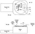
- FIG. 1shows a first embodiment of a printer 20 of the invention.
- printer 20comprises a housing 21 having a print engine 22 that applies markings or otherwise forms an image on a receiver medium 24 .
- Print engine 22can record images on receiver medium 24 using a variety of known technologies including, but not limited to, conventional four color offset separation printing or other contact printing, silk screening, dry electrophotography such as is used in the NexPress 2100 printer sold by Eastman Kodak Company, Rochester, N.Y., USA, thermal printing technology, drop on demand ink jet technology and continuous inkjet technology.
- print engine 22will be described as being of a type that generates color images. However, it will be appreciated that this is not necessary and that the claimed methods and apparatuses herein can be practiced with a print engine 22 , monotone images such as black and white, grayscale or sepia toned images.
- a medium advance 26is used to remove receiver medium 24 from a supply area 27 and to position receiver medium 24 and/or print engine 22 relative to each other to facilitate recording of an image on receiver medium 24 .
- Medium advance 26can comprise any number of well-known systems for moving receiver medium 24 within printer 20 , including a motor 28 driving pinch rollers 30 , a motorized platen roller (not shown) or other well-known systems for the movement of paper or other types of receiver medium 24 .
- a processor 34operates print engine 22 and medium advance 26 .
- Processor 34can include, but is not limited to, a programmable digital computer, a programmable microprocessor, a programmable logic processor, a series of electronic circuits, a series of electronic circuits reduced to the form of an integrated circuit, or a series of discrete components.
- Processor 34operates printer 20 based upon input signals sent to and/or received from a user input system 36 , sensors 38 , a status indicator system 39 , a memory 40 and a communication system 54 .
- User input system 36can comprise any form of transducer or other device capable of receiving an input from a user and converting this input into a form that can be used by processor 34 .
- user input system 36can comprise a two state button, a dial, a keypad system, a touch screen input, a touch pad input, a 4-way switch, a 6-way switch, an 8-way switch, a stylus system, a trackball system, a joystick system, a voice recognition system, a gesture recognition system a keyboard, a remote control or other such systems.
- user input system 36includes an optional remote input controls 58 and a local input controls 68 including local input controls 68 a - 68 d.
- Sensors 38are optional and can include light sensors, temperature sensors, humidity sensors and other sensors known in the art that can be used to detect conditions within printer 20 or within the environment surrounding printer 20 and to convert this information into a form that can be used by processor 34 in governing operation of print engine 22 or other systems of printer 20 .
- Sensors 38can include audio sensors adapted to capture sounds.
- Sensors 38can also include positioning and other sensors used internally to monitor printer operations.
- Status indicator system 39is optional and typically comprises some form of device capable of generating a human detectible output such as an arrangement of organic or inorganic light emitter diodes (LED), a monochrome liquid crystal display, light, audio signal generator, or like device and appropriate control circuitry.
- status indicator system 39is illustrated as comprising a system for driving a set of four status indicators 39 a, 39 b , 39 c and 39 d which can be, for example, LED type indicators.
- Memory 40can include conventional memory devices including solid state, magnetic, optical or other data storage devices. Memory 40 can be fixed within printer 20 or it can be removable. In the embodiment of FIG. 1 , printer 20 is shown having a hard drive 42 , a disk drive 44 for a removable disk such as an optical, magnetic or other disk memory (not shown) and a memory card slot 46 that holds a removable memory 48 such as a removable memory card and has a removable memory card interface 50 for communicating with removable memory 48 . Data including but not limited to control programs, digital images and metadata can also be stored in a remote memory system 52 that is external to printer 20 such as a personal computer, computer network or other digital memory system such as a so called “WI-FI” enabled memory card.
- a remote memory system 52that is external to printer 20 such as a personal computer, computer network or other digital memory system such as a so called “WI-FI” enabled memory card.
- printer 20has a communication system 54 that can be used to communicate with a remote memory system 52 , a remote display 56 , remote input controls 58 , local input controls 68 , and/or a computer network such as a telecommunication network (not shown).
- Remote input controls 58can take a variety of forms, including but not limited to the remote keyboard 58 a , remote mouse 58 b or remote control handheld device 58 c illustrated in FIG. 1 .
- Remote display 56 and/or remote input controls 58can communicate with communication system 54 wirelessly as illustrated or can communicate in a wired fashion.
- local input controls 68can take a variety of forms and can be connected to processor 34 using a wired or wireless connection.
- a local display 66can be provided for use with local input controls 68 .
- Communication system 54can have circuits and systems that are arranged to communicate data using whatever formats are selected for such communication and can comprise for example, one or more optical, radio frequency or other transducer circuits or other systems that convert image and other data into a form that can be conveyed to display device 110 using an optical signal, radio frequency signal or other forms of signals.
- Printer 20further comprises printer electrical interface 90 that can provide a communication connection between printer processor 34 and a display device 110 and that can include connections to provide a path for electrical energy to flow from printer 20 to display device 110 during docked operations.
- Electrical interface 90may use any well-known electrical interface, such as the universal serial bus (USB) interface specification, the IEEE 1394 interface specification, or other cable interface or card interface specifications to effect communications therebetween. Where desired, electrical interface 90 can use opto-electrical circuits for exchanging data.
- some portion of the communications described hereinafter between printer 20 and a docked display device 110can be made in other ways such as by way of wireless communication.
- communication system 54is adapted to communicate with a display device 110 to exchange control signals, data or other information with display device 110 .
- Such communicationcan be made using a wired or wireless communication scheme such as those that comply with any known standards for wireless radio frequency or optical communication such as IEEE 802.11 IrDa, Wi-fi and others.
- Communication system 54provides processor 34 with information and instructions from signals received thereby.
- printer 20has a display device interface 100 having a contact surface 102 that is shaped to receive a display device 110 and to interact with a housing 111 of display device 110 to position display device 110 so that display device 110 can interact with electrical interface 90 .
- Display device 110can comprise any form of digital device having an image display 112 , an electrical connector 116 that is adapted to cooperate with electrical interface 90 to permit the exchange of data and/or electrical energy and, a display device control system 118 that allows data or other signals received by display device 110 from processor 34 to influence what is presented on image display 112 .
- display device 110will have a display device memory 120 having digital image data such as still images, video clips, audio data and combinations thereof that are stored therein that can be used by printer 20 to generate printed images.
- display device 110comprises any of a wide variety of devices including, but not limited to, cellular telephones, photo-viewing devices such as the Kodak Easyshare Picture Viewer sold by Eastman Kodak Company, Rochester, N.Y., U.S.A., or the IPOD Picture Viewer sold by Apple Computer, Cupertino, Calif., U.S.A., digital cameras and personal digital assistants.
- display device 110is shown in the optional form of a digital camera 124 .
- Digital camera 124comprises the above-described components of a display device 110 and further includes a user input system 126 and an image capture system 140 .
- user input system 126includes a capture button 128 , mode selector 130 , four-way controller 132 , “yes” button 134 and “no” button 136 and a “share” button 138 . It will be appreciated that a user input system 126 can have a wide variety of other user input devices.
- Digital camera 124further comprises an image capture system 140 having a lens system 142 , imager 144 , audio capture system 146 and signal processor 148 adapted to capture images in response to a capture signal from control system 118 .
- control system 118sends such a capture signal when capture button 128 is depressed.
- printer 20does not have an image display, however printer 20 is adapted to send signals to digital camera 124 that can influence what is presented on image display 112 .
- image display 112allows image display 112 to be used for a variety of purposes such as selecting images for printing, editing images, adding text or other information to images, presenting images and the like.
- a wide variety of applications of this combinationare described in greater detail in the following commonly assigned U.S. patent application Ser. No.
- processor 34 of printer 20can, by way of communication system 54 and/or electrical interface 90 utilize image capture system 140 , audio capture system 146 and/or signal processor 148 of the digital camera 124 embodiment of display device 110 for any of a variety of purposes.
- processor 34can be used by processor 34 to speed the processing of images for editing, for printing or for other purposes so that, when display device 110 is docked to printer 20 , printer 20 is capable of printing, editing or otherwise processing images at a higher rate of speed.
- the combinationcan be used to enable features that printer 20 will not be enabled to perform in the absence of a docked display device 110 .
- processor 34may not be adapted to perform advanced editing techniques alone, but could perform such tasks in combination with a display device having a memory 120 and signal processor 148 .
- display device interface 100is adjustably joined to housing 21 .
- display device interface 100is rotatably joined to housing 21 in a manner that allows the image display 112 to be oriented in multiple positions relative to housing 21 , some examples of which are illustrated in FIGS. 4-8 , while also maintaining the electrical connection between electrical interface 90 , electrical connector 116 and display device 110 .
- Such rotationcan enable continuously variable positioning of housing 21 at a range of positions between those illustrated in FIGS. 4-8 or can enable positioning only at selected positions within such a range.
- the range of positions illustrated in FIGS. 2-8is exemplary only and that printer 20 of FIGS. 4-8 can be adapted to provide any range of desired range of movement.
- electrical linkage 150between processor 34 and electrical interface 90 that can be readily readjusted.
- an electrical connectorcan comprise a flexible ribbon.
- electrical linkage 150can comprise other conventional structures such as slip rings, tracks, wires, optical connections, and the like.
- local input controls 68 and status indicators 39 a - 39 d of indicator system 39have been illustrated as being positioned on display device interface 100 . This allows local input controls 68 to move in concert with display device interface 100 so that a user can more easily access to such controls. However, it is possible to provide similar effects without placing local input controls 68 on display device interface 100 .
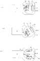
- FIGS. 9 and 10show another embodiment of a printer 20 .
- printer 20has local input controls 68 a - 68 d and status indicators 39 a - 39 d fixed to housing 21 and do not move with display device interface 100 .
- This problemcan be solved by providing a user with the ability to rotate a docked display device 110 so that image display 112 can be seen from any of a range of positions relative to housing 10 . More specifically, printer 20 of FIGS.
- 9 and 10uses a portion of image display 112 of display device 110 to present status indicators that provide the same information that is provided by status indicators 39 a - 39 d.
- the information presented by status indicators 39 a - 39 dcan be made viewable from any direction relative to housing 21 , without requiring that status indicators 39 a - 39 d be physically movable.
- printer 20can also provide the equivalent of adjustably located local user input controls 68 a - 68 d by using some of the buttons 128 and 134 - 138 of display device 110 as surrogates for the local user input controls 68 a - 68 d when display device 110 is docked to printer 20 .
- the buttons 128 and 134 - 138 of display device 110also rotate when display device 110 is rotated.
- processor 34 and display device 110can be operable in at least one docked mode wherein at least one of buttons 128 and 134 - 138 on display device 110 can be actuated so that user input system 126 provides signals that processor 34 can interpret in the same manner as one of local input controls 68 a - 68 d.
- display device 110can present graphic images on image display 112 indicating which controls of display device 110 can be used to perform functions similar to fixed position type local input controls 68 a - 68 d.
- Processor 34can be adapted to cause this type of user interaction to occur when processor 34 is instructed to operate in such a manner, such as by way of user input system 36 .
- processor 34can automatically cause this type of user interaction to occur when signals from sensor 38 indicate that such interaction is appropriate.
- sensors 38can include a position sensor of conventional design (not shown) that can track the position of display device interface 100 or that can otherwise sense when display device interface 100 is positioned in a manner that suggests that a user may not have ready access to local input controls 68 a - 68 d or ready viewing of status indicators 39 a - 39 d and that can provide signals to processor 34 .
- processor 34can optionally operate display device 110 in a manner that is intended to provide a virtual equivalent 152 , any of local input controls 68 a - 68 d or status indicators 39 a - 39 d. In the embodiment illustrated in FIGS.
- image display 112comprises a touch sensitive display
- virtual equivalents 152 of the local controlscan be presented on image display 112 as necessary and any contact with portions of image display 112 associated with virtual equivalents 152 can be sensed and used as input for printer 20 .
- FIGS. 11 , 12 and 13show another embodiment of printer 20 .
- an adjustment surface 160is provided on housing 21 .
- Adjustment surface 160is also movably mounted with respect to the housing with at least some of local input controls 68 and/or some of status indicators 39 a - 39 d being positioned on adjustment surface 160 so that the position of controls 68 a - 68 d , and/or status indicators 39 a - 39 d can be adjusted with respect to the position of display device interface 100 and external housing 21 so as to provide users with greater flexibility in arranging the controls for the system.
- display device interface 100 locatedis rotatably mounted to the external housing about an axis of rotation A and the adjustment surface 160 is positioned on an annular ring that rotates generally about axis of rotation A.
- display device interface 100can be adapted to move along one or more axes that are separate from one or more axes of movement of display device interface 100 .
- FIGS. 14 and 15show end views of still another embodiment of printer 20 , wherein printer 20 has a horizontal dimension, a vertical dimension and a depth dimension wherein said display device receiving area is adapted to rotatably position the display device interface 100 so that image display 112 can be viewed from a range of at least two of the horizontal, vertical and depth dimensions.
- display device interface 100is illustrated having contact surfaces 102 that are adjustable to enable a variation in the angle of view of image display 112 .
- conventional structurescan be used to provide a variable position of display device interface 100 along at least two of a vertical, horizontal and/or depth dimension relative to display device interface 100 .
Landscapes
- Engineering & Computer Science (AREA)
- Multimedia (AREA)
- Signal Processing (AREA)
- Accessory Devices And Overall Control Thereof (AREA)
- User Interface Of Digital Computer (AREA)
- Printers Characterized By Their Purpose (AREA)
Abstract
Description
- 20 printer
- 21 housing
- 22 print engine
- 24 receiver medium
- 26 medium advance
- 27 supply area
- 28 motor
- 30 pinch rollers
- 34 processor
- 36 user input system
- 38 sensors
- 39 indicator system
- 39a-dstatus indicators
- 40 memory
- 42 hard drive
- 44 disk drive
- 46 memory card slot
- 48 removable memory
- 50 memory card interface
- 52 remote memory system
- 54 communication system
- 56 remote display
- 58 remote input controls
- 58aremote keyboard
- 58bremote mouse
- 58cremote control handheld device
- 66 local display
- 68 local input controls
- 68a-68dlocal input controls
- 90 electrical interface
- 100 display device interface
- 102 contact surface
- 110 display device
- 111 housing
- 112 image display
- 116 electrical connector
- 118 display device control system
- 120 display device memory
- 124 digital camera
- 126 user input system
- 128 capture button
- 130 mode selector
- 132 four-way controller
- 134 “yes” button
- 136 “no” button
- 138 “share” button
- 140 image capture system
- 142 lens system
- 144 imager
- 146 audio capture system
- 148 signal processor
- 150 electrical linkage
- 152 virtual equivalents
- 154 icons
- 156 icons
- 160 adjustment surface
Claims (10)
Priority Applications (4)
| Application Number | Priority Date | Filing Date | Title |
|---|---|---|---|
| US11/312,909US7684090B2 (en) | 2005-12-20 | 2005-12-20 | Digital printer for use with docked display device |
| PCT/US2006/048622WO2007075795A2 (en) | 2005-12-20 | 2006-12-20 | Digital printer for use with docked display device |
| EP06847834AEP1989870A2 (en) | 2005-12-20 | 2006-12-20 | Digital printer for use with docked display device |
| JP2008547493AJP5047987B2 (en) | 2005-12-20 | 2006-12-20 | Printer |
Applications Claiming Priority (1)
| Application Number | Priority Date | Filing Date | Title |
|---|---|---|---|
| US11/312,909US7684090B2 (en) | 2005-12-20 | 2005-12-20 | Digital printer for use with docked display device |
Publications (2)
| Publication Number | Publication Date |
|---|---|
| US20070139719A1 US20070139719A1 (en) | 2007-06-21 |
| US7684090B2true US7684090B2 (en) | 2010-03-23 |
Family
ID=38173085
Family Applications (1)
| Application Number | Title | Priority Date | Filing Date |
|---|---|---|---|
| US11/312,909Active2029-01-20US7684090B2 (en) | 2005-12-20 | 2005-12-20 | Digital printer for use with docked display device |
Country Status (4)
| Country | Link |
|---|---|
| US (1) | US7684090B2 (en) |
| EP (1) | EP1989870A2 (en) |
| JP (1) | JP5047987B2 (en) |
| WO (1) | WO2007075795A2 (en) |
Cited By (1)
| Publication number | Priority date | Publication date | Assignee | Title |
|---|---|---|---|---|
| US20120320226A1 (en)* | 2011-06-14 | 2012-12-20 | Chee Meng Chen | Stationary printing apparatus with camera |
Families Citing this family (5)
| Publication number | Priority date | Publication date | Assignee | Title |
|---|---|---|---|---|
| JP2003076533A (en)* | 2001-06-19 | 2003-03-14 | Fuji Photo Film Co Ltd | Management method and management system for image forming device |
| US20120081315A1 (en) | 2010-10-01 | 2012-04-05 | Imerj LLC | Keyboard spanning multiple screens |
| US20070240174A1 (en)* | 2006-03-18 | 2007-10-11 | Radioshack Corporation | Apparatus and method for receiving a portable media player to perform an accessory function |
| US9182935B2 (en) | 2011-09-27 | 2015-11-10 | Z124 | Secondary single screen mode activation through menu option |
| JP6794895B2 (en)* | 2017-03-28 | 2020-12-02 | カシオ計算機株式会社 | Electronic devices, location identification systems, location identification methods and programs |
Citations (36)
| Publication number | Priority date | Publication date | Assignee | Title |
|---|---|---|---|---|
| US4484349A (en) | 1982-03-11 | 1984-11-20 | Environmental Research Institute Of Michigan | Parallel pipeline image processor |
| EP0382044A2 (en) | 1989-02-10 | 1990-08-16 | Polaroid Corporation | Electronic camera system with detachable printer |
| US5164831A (en) | 1990-03-15 | 1992-11-17 | Eastman Kodak Company | Electronic still camera providing multi-format storage of full and reduced resolution images |
| US5330415A (en) | 1989-02-27 | 1994-07-19 | Air-Shields, Inc. | Incubator with remote control and display module |
| EP0674435A1 (en) | 1994-02-28 | 1995-09-27 | Canon Kabushiki Kaisha | Image sensing apparatus |
| US5477264A (en) | 1994-03-29 | 1995-12-19 | Eastman Kodak Company | Electronic imaging system using a removable software-enhanced storage device |
| JPH0811845A (en) | 1994-06-24 | 1996-01-16 | Toyo Eng Corp | Method and device for detecting seal portion of continuous pouch ribbon |
| US5600445A (en) | 1993-03-23 | 1997-02-04 | Ricoh Company, Ltd. | Modular copying system using light wave, electric wave, or sonic wave interconnections |
| US5606420A (en) | 1990-11-29 | 1997-02-25 | Minolta Camera Kabushiki Kaisha | Camera system including a camera section and a reproduction section separately attachable to the camera section |
| US5694289A (en) | 1994-08-10 | 1997-12-02 | Ricoh Company, Ltd. | Information processing apparatus with operation panel which is changeable in direction of operation |
| WO1997050243A1 (en) | 1996-06-25 | 1997-12-31 | Casio Computer Co., Ltd. | Printing apparatus and printing system |
| EP0869656A2 (en) | 1997-04-04 | 1998-10-07 | Eastman Kodak Company | Printer parameter compensation by a host camera |
| US5844689A (en) | 1995-11-02 | 1998-12-01 | Canon Kabushiki Kaisha | System for image formation and image display based on an external image signal |
| EP0912035A2 (en) | 1997-10-23 | 1999-04-28 | Eastman Kodak Company | System and method for using a single intelligence circuit for a plurality of imaging rendering components |
| EP0920184A2 (en) | 1997-11-20 | 1999-06-02 | Casio Computer Co., Ltd. | Electronic camera system |
| JPH11179998A (en) | 1997-12-18 | 1999-07-06 | Kyocera Corp | Printer |
| EP0949804A2 (en) | 1998-04-08 | 1999-10-13 | Hewlett-Packard Company | Imaging and printing systems |
| EP0973321A2 (en) | 1998-07-17 | 2000-01-19 | Sony Corporation | Photographing apparatus |
| US6115137A (en) | 1996-12-06 | 2000-09-05 | Canon Kabushiki Kaisha | Image processing system, digital camera, and printing apparatus |
| US6146523A (en) | 1995-02-13 | 2000-11-14 | Aksys, Ltd. | User interface and method for control of medical instruments, such as dialysis machines |
| US20020071035A1 (en) | 2000-12-07 | 2002-06-13 | Sobol Robert E. | Digital camera docking station |
| US20020093583A1 (en) | 2001-01-16 | 2002-07-18 | Takeyoshi Ito | Digital camera, cradle and camera system |
| US20020113996A1 (en) | 2001-02-16 | 2002-08-22 | Minolta Co., Ltd. | Data supplier, printer and print system |
| US6466278B1 (en) | 2000-01-06 | 2002-10-15 | Icebox, Llc | Appliances |
| US20020149695A1 (en) | 2001-04-12 | 2002-10-17 | Yasunobu Kayanuma | Cradle for information apparatus, cradle for digital camera and camera system |
| US20020186317A1 (en) | 2001-06-11 | 2002-12-12 | Yasunobu Kayanuma | Cradle for digital camera |
| US20020186319A1 (en) | 2001-06-05 | 2002-12-12 | Eastman Kodak Company | Docking station assembly for transmitting digital files |
| US6587140B2 (en) | 1997-10-23 | 2003-07-01 | Eastman Kodak Company | System and method for using a single intelligence circuit in both a digital camera and printer |
| US20040004671A1 (en) | 2002-06-25 | 2004-01-08 | Fuji Photo Film Co., Ltd. | Digital camera system |
| WO2004049693A1 (en) | 2002-11-27 | 2004-06-10 | Casio Computer Co., Ltd. | Electronic apparatus, connecting mounting for electronic apparatus, and connecting system including electronic apparatus and connecting mounting |
| US6774951B2 (en)* | 2000-02-24 | 2004-08-10 | Sony Corporation | Digital broadcast reception system, digital broadcast reception apparatus and digital broadcast printing apparatus |
| US6785126B2 (en) | 2001-05-07 | 2004-08-31 | Ttools, Llc | Protective case and keyboard system for a handheld computer |
| US20040169327A1 (en) | 2003-02-28 | 2004-09-02 | Eastman Kodak Company | Imaging system and media supply for use in imaging system |
| US20040212822A1 (en) | 2003-04-22 | 2004-10-28 | Schinner Charles E. | Printer and docking station having a digital camera docking port with an image magnifier |
| US20050088572A1 (en) | 2003-10-28 | 2005-04-28 | Pandit Amol S. | System and method for a camera docking station |
| US20060112375A1 (en)* | 2004-11-16 | 2006-05-25 | Schneider John R | Computer workstation resource usage monitoring system |
Family Cites Families (2)
| Publication number | Priority date | Publication date | Assignee | Title |
|---|---|---|---|---|
| JP2003153179A (en)* | 2001-11-09 | 2003-05-23 | Olympus Optical Co Ltd | Image print system |
| US20040169727A1 (en)* | 2003-02-27 | 2004-09-02 | Romano Nathan J. | System and method for viewing and selecting images for printing |
- 2005
- 2005-12-20USUS11/312,909patent/US7684090B2/enactiveActive
- 2006
- 2006-12-20WOPCT/US2006/048622patent/WO2007075795A2/enactiveApplication Filing
- 2006-12-20JPJP2008547493Apatent/JP5047987B2/ennot_activeExpired - Fee Related
- 2006-12-20EPEP06847834Apatent/EP1989870A2/ennot_activeCeased
Patent Citations (39)
| Publication number | Priority date | Publication date | Assignee | Title |
|---|---|---|---|---|
| US4484349A (en) | 1982-03-11 | 1984-11-20 | Environmental Research Institute Of Michigan | Parallel pipeline image processor |
| EP0382044A2 (en) | 1989-02-10 | 1990-08-16 | Polaroid Corporation | Electronic camera system with detachable printer |
| US5330415A (en) | 1989-02-27 | 1994-07-19 | Air-Shields, Inc. | Incubator with remote control and display module |
| US5164831A (en) | 1990-03-15 | 1992-11-17 | Eastman Kodak Company | Electronic still camera providing multi-format storage of full and reduced resolution images |
| US5606420A (en) | 1990-11-29 | 1997-02-25 | Minolta Camera Kabushiki Kaisha | Camera system including a camera section and a reproduction section separately attachable to the camera section |
| US5600445A (en) | 1993-03-23 | 1997-02-04 | Ricoh Company, Ltd. | Modular copying system using light wave, electric wave, or sonic wave interconnections |
| EP0674435A1 (en) | 1994-02-28 | 1995-09-27 | Canon Kabushiki Kaisha | Image sensing apparatus |
| US5477264A (en) | 1994-03-29 | 1995-12-19 | Eastman Kodak Company | Electronic imaging system using a removable software-enhanced storage device |
| JPH0811845A (en) | 1994-06-24 | 1996-01-16 | Toyo Eng Corp | Method and device for detecting seal portion of continuous pouch ribbon |
| US5694289A (en) | 1994-08-10 | 1997-12-02 | Ricoh Company, Ltd. | Information processing apparatus with operation panel which is changeable in direction of operation |
| US6146523A (en) | 1995-02-13 | 2000-11-14 | Aksys, Ltd. | User interface and method for control of medical instruments, such as dialysis machines |
| US5844689A (en) | 1995-11-02 | 1998-12-01 | Canon Kabushiki Kaisha | System for image formation and image display based on an external image signal |
| WO1997050243A1 (en) | 1996-06-25 | 1997-12-31 | Casio Computer Co., Ltd. | Printing apparatus and printing system |
| US6115137A (en) | 1996-12-06 | 2000-09-05 | Canon Kabushiki Kaisha | Image processing system, digital camera, and printing apparatus |
| EP0869656A2 (en) | 1997-04-04 | 1998-10-07 | Eastman Kodak Company | Printer parameter compensation by a host camera |
| US6738090B2 (en) | 1997-10-23 | 2004-05-18 | Eastman Kodak Company | System and method for using a single intelligence circuit for a plurality of imaging rendering components |
| US6587140B2 (en) | 1997-10-23 | 2003-07-01 | Eastman Kodak Company | System and method for using a single intelligence circuit in both a digital camera and printer |
| US6747689B1 (en) | 1997-10-23 | 2004-06-08 | Eastman Kodak Company | Method of operating a multiple component electronic imaging system |
| EP0912035A2 (en) | 1997-10-23 | 1999-04-28 | Eastman Kodak Company | System and method for using a single intelligence circuit for a plurality of imaging rendering components |
| EP0920184A2 (en) | 1997-11-20 | 1999-06-02 | Casio Computer Co., Ltd. | Electronic camera system |
| JPH11179998A (en) | 1997-12-18 | 1999-07-06 | Kyocera Corp | Printer |
| EP0949804A2 (en) | 1998-04-08 | 1999-10-13 | Hewlett-Packard Company | Imaging and printing systems |
| EP0973321A2 (en) | 1998-07-17 | 2000-01-19 | Sony Corporation | Photographing apparatus |
| US6693665B1 (en) | 1998-07-17 | 2004-02-17 | Sony Corporation | System and apparatus for facilitating printing of images from an electronic camera |
| US6466278B1 (en) | 2000-01-06 | 2002-10-15 | Icebox, Llc | Appliances |
| US6774951B2 (en)* | 2000-02-24 | 2004-08-10 | Sony Corporation | Digital broadcast reception system, digital broadcast reception apparatus and digital broadcast printing apparatus |
| US20020071035A1 (en) | 2000-12-07 | 2002-06-13 | Sobol Robert E. | Digital camera docking station |
| US20020093583A1 (en) | 2001-01-16 | 2002-07-18 | Takeyoshi Ito | Digital camera, cradle and camera system |
| US20020113996A1 (en) | 2001-02-16 | 2002-08-22 | Minolta Co., Ltd. | Data supplier, printer and print system |
| US20020149695A1 (en) | 2001-04-12 | 2002-10-17 | Yasunobu Kayanuma | Cradle for information apparatus, cradle for digital camera and camera system |
| US6785126B2 (en) | 2001-05-07 | 2004-08-31 | Ttools, Llc | Protective case and keyboard system for a handheld computer |
| US20020186319A1 (en) | 2001-06-05 | 2002-12-12 | Eastman Kodak Company | Docking station assembly for transmitting digital files |
| US20020186317A1 (en) | 2001-06-11 | 2002-12-12 | Yasunobu Kayanuma | Cradle for digital camera |
| US20040004671A1 (en) | 2002-06-25 | 2004-01-08 | Fuji Photo Film Co., Ltd. | Digital camera system |
| WO2004049693A1 (en) | 2002-11-27 | 2004-06-10 | Casio Computer Co., Ltd. | Electronic apparatus, connecting mounting for electronic apparatus, and connecting system including electronic apparatus and connecting mounting |
| US20040169327A1 (en) | 2003-02-28 | 2004-09-02 | Eastman Kodak Company | Imaging system and media supply for use in imaging system |
| US20040212822A1 (en) | 2003-04-22 | 2004-10-28 | Schinner Charles E. | Printer and docking station having a digital camera docking port with an image magnifier |
| US20050088572A1 (en) | 2003-10-28 | 2005-04-28 | Pandit Amol S. | System and method for a camera docking station |
| US20060112375A1 (en)* | 2004-11-16 | 2006-05-25 | Schneider John R | Computer workstation resource usage monitoring system |
Non-Patent Citations (3)
| Title |
|---|
| CompactFlash Association; CF+ and CompactFlash Specification Revision 1.4; 1998-99; pp. 1-105. |
| Eastman Kodak Company, "Kodak EasyShare Photo Frame Dock 2", www.kodak.com. |
| Japan Electronic Industry Development Association; "Digital Still Camera Image File Format Standard"; JEIDA-49-1998; pp. 1-168. |
Cited By (1)
| Publication number | Priority date | Publication date | Assignee | Title |
|---|---|---|---|---|
| US20120320226A1 (en)* | 2011-06-14 | 2012-12-20 | Chee Meng Chen | Stationary printing apparatus with camera |
Also Published As
| Publication number | Publication date |
|---|---|
| WO2007075795A2 (en) | 2007-07-05 |
| JP2009520615A (en) | 2009-05-28 |
| JP5047987B2 (en) | 2012-10-10 |
| US20070139719A1 (en) | 2007-06-21 |
| EP1989870A2 (en) | 2008-11-12 |
| WO2007075795A3 (en) | 2007-11-15 |
Similar Documents
| Publication | Publication Date | Title |
|---|---|---|
| US7503011B2 (en) | Modular digital imaging system user interface | |
| RU2460234C1 (en) | Configuration device, image displaying device, methods of their control and software | |
| WO2015046900A1 (en) | Method and device for sharing content | |
| US7293187B2 (en) | Image sensing apparatus and power managing method | |
| US20100118327A1 (en) | All-in-One Device with Integrated Monitor | |
| WO2007075795A2 (en) | Digital printer for use with docked display device | |
| US20080309993A1 (en) | Executing operations in connection with one or more images with a printer | |
| US20070041029A1 (en) | Image forming apparatus with an image editing function and a method thereof | |
| US20090021797A1 (en) | All-In-One Device With Integrated Monitor | |
| US20090219580A1 (en) | Scanning system with real-time display unit | |
| US20050174349A1 (en) | Image rendering apparatus with print preview projection mechanism | |
| US20020196477A1 (en) | Scanner with wireless connections | |
| US7704000B2 (en) | Printer dock with two position tray | |
| CN100480840C (en) | Data Projector with internal printer | |
| US9077826B2 (en) | Data printing system, portable terminal device and computer-readable medium | |
| JP2009143005A (en) | Printer | |
| US10097703B2 (en) | Image printing device and method using display device | |
| CN100362497C (en) | Recording apparatus, image supply apparatus, recording system, and control method thereof | |
| KR20170069597A (en) | Image forming apparatus, portable display apparatus, image forming method and displaying method | |
| JPH09314918A (en) | Portable electronic devices | |
| JP2005130143A (en) | Printing system, imaging apparatus, printing method, computer program, and computer-readable storage medium | |
| US8351071B2 (en) | Print control apparatus, print apparatus, print system, print method, and storage medium | |
| KR100657342B1 (en) | Image storage device and method | |
| JP2000232541A (en) | Image processing device | |
| JP2013136154A (en) | Electronic blackboard system, and electronic blackboard device and mobile terminal used therein |
Legal Events
| Date | Code | Title | Description |
|---|---|---|---|
| AS | Assignment | Owner name:EASTMAN KODAK COMPANY,NEW YORK Free format text:ASSIGNMENT OF ASSIGNORS INTEREST;ASSIGNORS:GOTHAM, DAVID R.;SWAYZE, SAMUEL F.;SIGNING DATES FROM 20051216 TO 20051219;REEL/FRAME:017359/0148 Owner name:EASTMAN KODAK COMPANY, NEW YORK Free format text:ASSIGNMENT OF ASSIGNORS INTEREST;ASSIGNORS:GOTHAM, DAVID R.;SWAYZE, SAMUEL F.;REEL/FRAME:017359/0148;SIGNING DATES FROM 20051216 TO 20051219 | |
| STCF | Information on status: patent grant | Free format text:PATENTED CASE | |
| AS | Assignment | Owner name:CITICORP NORTH AMERICA, INC., AS AGENT, NEW YORK Free format text:SECURITY INTEREST;ASSIGNORS:EASTMAN KODAK COMPANY;PAKON, INC.;REEL/FRAME:028201/0420 Effective date:20120215 | |
| FEPP | Fee payment procedure | Free format text:PAYOR NUMBER ASSIGNED (ORIGINAL EVENT CODE: ASPN); ENTITY STATUS OF PATENT OWNER: LARGE ENTITY | |
| AS | Assignment | Owner name:FAR EAST DEVELOPMENT LTD., NEW YORK Free format text:PATENT RELEASE;ASSIGNORS:CITICORP NORTH AMERICA, INC.;WILMINGTON TRUST, NATIONAL ASSOCIATION;REEL/FRAME:029913/0001 Effective date:20130201 Owner name:EASTMAN KODAK INTERNATIONAL CAPITAL COMPANY, INC., Free format text:PATENT RELEASE;ASSIGNORS:CITICORP NORTH AMERICA, INC.;WILMINGTON TRUST, NATIONAL ASSOCIATION;REEL/FRAME:029913/0001 Effective date:20130201 Owner name:LASER-PACIFIC MEDIA CORPORATION, NEW YORK Free format text:PATENT RELEASE;ASSIGNORS:CITICORP NORTH AMERICA, INC.;WILMINGTON TRUST, NATIONAL ASSOCIATION;REEL/FRAME:029913/0001 Effective date:20130201 Owner name:EASTMAN KODAK COMPANY, NEW YORK Free format text:PATENT RELEASE;ASSIGNORS:CITICORP NORTH AMERICA, INC.;WILMINGTON TRUST, NATIONAL ASSOCIATION;REEL/FRAME:029913/0001 Effective date:20130201 Owner name:KODAK PORTUGUESA LIMITED, NEW YORK Free format text:PATENT RELEASE;ASSIGNORS:CITICORP NORTH AMERICA, INC.;WILMINGTON TRUST, NATIONAL ASSOCIATION;REEL/FRAME:029913/0001 Effective date:20130201 Owner name:NPEC INC., NEW YORK Free format text:PATENT RELEASE;ASSIGNORS:CITICORP NORTH AMERICA, INC.;WILMINGTON TRUST, NATIONAL ASSOCIATION;REEL/FRAME:029913/0001 Effective date:20130201 Owner name:KODAK (NEAR EAST), INC., NEW YORK Free format text:PATENT RELEASE;ASSIGNORS:CITICORP NORTH AMERICA, INC.;WILMINGTON TRUST, NATIONAL ASSOCIATION;REEL/FRAME:029913/0001 Effective date:20130201 Owner name:KODAK REALTY, INC., NEW YORK Free format text:PATENT RELEASE;ASSIGNORS:CITICORP NORTH AMERICA, INC.;WILMINGTON TRUST, NATIONAL ASSOCIATION;REEL/FRAME:029913/0001 Effective date:20130201 Owner name:KODAK PHILIPPINES, LTD., NEW YORK Free format text:PATENT RELEASE;ASSIGNORS:CITICORP NORTH AMERICA, INC.;WILMINGTON TRUST, NATIONAL ASSOCIATION;REEL/FRAME:029913/0001 Effective date:20130201 Owner name:CREO MANUFACTURING AMERICA LLC, WYOMING Free format text:PATENT RELEASE;ASSIGNORS:CITICORP NORTH AMERICA, INC.;WILMINGTON TRUST, NATIONAL ASSOCIATION;REEL/FRAME:029913/0001 Effective date:20130201 Owner name:FPC INC., CALIFORNIA Free format text:PATENT RELEASE;ASSIGNORS:CITICORP NORTH AMERICA, INC.;WILMINGTON TRUST, NATIONAL ASSOCIATION;REEL/FRAME:029913/0001 Effective date:20130201 Owner name:QUALEX INC., NORTH CAROLINA Free format text:PATENT RELEASE;ASSIGNORS:CITICORP NORTH AMERICA, INC.;WILMINGTON TRUST, NATIONAL ASSOCIATION;REEL/FRAME:029913/0001 Effective date:20130201 Owner name:KODAK AVIATION LEASING LLC, NEW YORK Free format text:PATENT RELEASE;ASSIGNORS:CITICORP NORTH AMERICA, INC.;WILMINGTON TRUST, NATIONAL ASSOCIATION;REEL/FRAME:029913/0001 Effective date:20130201 Owner name:KODAK IMAGING NETWORK, INC., CALIFORNIA Free format text:PATENT RELEASE;ASSIGNORS:CITICORP NORTH AMERICA, INC.;WILMINGTON TRUST, NATIONAL ASSOCIATION;REEL/FRAME:029913/0001 Effective date:20130201 Owner name:KODAK AMERICAS, LTD., NEW YORK Free format text:PATENT RELEASE;ASSIGNORS:CITICORP NORTH AMERICA, INC.;WILMINGTON TRUST, NATIONAL ASSOCIATION;REEL/FRAME:029913/0001 Effective date:20130201 Owner name:PAKON, INC., INDIANA Free format text:PATENT RELEASE;ASSIGNORS:CITICORP NORTH AMERICA, INC.;WILMINGTON TRUST, NATIONAL ASSOCIATION;REEL/FRAME:029913/0001 Effective date:20130201 | |
| AS | Assignment | Owner name:INTELLECTUAL VENTURES FUND 83 LLC, NEVADA Free format text:ASSIGNMENT OF ASSIGNORS INTEREST;ASSIGNOR:EASTMAN KODAK COMPANY;REEL/FRAME:030215/0289 Effective date:20130201 | |
| FPAY | Fee payment | Year of fee payment:4 | |
| AS | Assignment | Owner name:MONUMENT PEAK VENTURES, LLC, TEXAS Free format text:ASSIGNMENT OF ASSIGNORS INTEREST;ASSIGNOR:INTELLECTUAL VENTURES FUND 83 LLC;REEL/FRAME:041941/0079 Effective date:20170215 | |
| FEPP | Fee payment procedure | Free format text:MAINTENANCE FEE REMINDER MAILED (ORIGINAL EVENT CODE: REM.) | |
| FEPP | Fee payment procedure | Free format text:7.5 YR SURCHARGE - LATE PMT W/IN 6 MO, LARGE ENTITY (ORIGINAL EVENT CODE: M1555) | |
| MAFP | Maintenance fee payment | Free format text:PAYMENT OF MAINTENANCE FEE, 8TH YEAR, LARGE ENTITY (ORIGINAL EVENT CODE: M1552) Year of fee payment:8 | |
| MAFP | Maintenance fee payment | Free format text:PAYMENT OF MAINTENANCE FEE, 12TH YEAR, LARGE ENTITY (ORIGINAL EVENT CODE: M1553); ENTITY STATUS OF PATENT OWNER: LARGE ENTITY Year of fee payment:12 | |
| IPR | Aia trial proceeding filed before the patent and appeal board: inter partes review | Free format text:TRIAL NO: IPR2022-00318 Opponent name:XEROX CORPORATION Effective date:20211215 | |
| AS | Assignment | Owner name:MONUMENT PEAK VENTURES, LLC, TEXAS Free format text:RELEASE BY SECURED PARTY;ASSIGNOR:INTELLECTUAL VENTURES FUND 83 LLC;REEL/FRAME:064599/0304 Effective date:20230728 |