US7683950B2 - Method and apparatus for correcting a channel dependent color aberration in a digital image - Google Patents
Method and apparatus for correcting a channel dependent color aberration in a digital imageDownload PDFInfo
- Publication number
- US7683950B2 US7683950B2US11/114,841US11484105AUS7683950B2US 7683950 B2US7683950 B2US 7683950B2US 11484105 AUS11484105 AUS 11484105AUS 7683950 B2US7683950 B2US 7683950B2
- Authority
- US
- United States
- Prior art keywords
- channel
- color
- sharpness
- mtf
- color channel
- Prior art date
- Legal status (The legal status is an assumption and is not a legal conclusion. Google has not performed a legal analysis and makes no representation as to the accuracy of the status listed.)
- Expired - Fee Related, expires
Links
Images


Classifications
- G—PHYSICS
- G06—COMPUTING OR CALCULATING; COUNTING
- G06T—IMAGE DATA PROCESSING OR GENERATION, IN GENERAL
- G06T5/00—Image enhancement or restoration
- G06T5/73—Deblurring; Sharpening
- G—PHYSICS
- G06—COMPUTING OR CALCULATING; COUNTING
- G06T—IMAGE DATA PROCESSING OR GENERATION, IN GENERAL
- G06T5/00—Image enhancement or restoration
- G06T5/10—Image enhancement or restoration using non-spatial domain filtering
- G—PHYSICS
- G06—COMPUTING OR CALCULATING; COUNTING
- G06T—IMAGE DATA PROCESSING OR GENERATION, IN GENERAL
- G06T5/00—Image enhancement or restoration
- G06T5/20—Image enhancement or restoration using local operators
- H—ELECTRICITY
- H04—ELECTRIC COMMUNICATION TECHNIQUE
- H04N—PICTORIAL COMMUNICATION, e.g. TELEVISION
- H04N1/00—Scanning, transmission or reproduction of documents or the like, e.g. facsimile transmission; Details thereof
- H04N1/46—Colour picture communication systems
- H04N1/56—Processing of colour picture signals
- H04N1/58—Edge or detail enhancement; Noise or error suppression, e.g. colour misregistration correction
- H—ELECTRICITY
- H04—ELECTRIC COMMUNICATION TECHNIQUE
- H04N—PICTORIAL COMMUNICATION, e.g. TELEVISION
- H04N25/00—Circuitry of solid-state image sensors [SSIS]; Control thereof
- H04N25/60—Noise processing, e.g. detecting, correcting, reducing or removing noise
- H04N25/61—Noise processing, e.g. detecting, correcting, reducing or removing noise the noise originating only from the lens unit, e.g. flare, shading, vignetting or "cos4"
- H04N25/611—Correction of chromatic aberration
- H—ELECTRICITY
- H04—ELECTRIC COMMUNICATION TECHNIQUE
- H04N—PICTORIAL COMMUNICATION, e.g. TELEVISION
- H04N25/00—Circuitry of solid-state image sensors [SSIS]; Control thereof
- H04N25/60—Noise processing, e.g. detecting, correcting, reducing or removing noise
- H04N25/61—Noise processing, e.g. detecting, correcting, reducing or removing noise the noise originating only from the lens unit, e.g. flare, shading, vignetting or "cos4"
- H04N25/615—Noise processing, e.g. detecting, correcting, reducing or removing noise the noise originating only from the lens unit, e.g. flare, shading, vignetting or "cos4" involving a transfer function modelling the optical system, e.g. optical transfer function [OTF], phase transfer function [PhTF] or modulation transfer function [MTF]
- H04N25/6153—Noise processing, e.g. detecting, correcting, reducing or removing noise the noise originating only from the lens unit, e.g. flare, shading, vignetting or "cos4" involving a transfer function modelling the optical system, e.g. optical transfer function [OTF], phase transfer function [PhTF] or modulation transfer function [MTF] for colour signals
- G—PHYSICS
- G06—COMPUTING OR CALCULATING; COUNTING
- G06T—IMAGE DATA PROCESSING OR GENERATION, IN GENERAL
- G06T2207/00—Indexing scheme for image analysis or image enhancement
- G06T2207/10—Image acquisition modality
- G06T2207/10024—Color image
- G—PHYSICS
- G06—COMPUTING OR CALCULATING; COUNTING
- G06T—IMAGE DATA PROCESSING OR GENERATION, IN GENERAL
- G06T2207/00—Indexing scheme for image analysis or image enhancement
- G06T2207/20—Special algorithmic details
- G06T2207/20048—Transform domain processing
- G06T2207/20056—Discrete and fast Fourier transform, [DFT, FFT]
- G—PHYSICS
- G06—COMPUTING OR CALCULATING; COUNTING
- G06T—IMAGE DATA PROCESSING OR GENERATION, IN GENERAL
- G06T2207/00—Indexing scheme for image analysis or image enhancement
- G06T2207/20—Special algorithmic details
- G06T2207/20172—Image enhancement details
- G06T2207/20192—Edge enhancement; Edge preservation
Definitions
- the present inventionrelates generally to the field of photography, and in particular to imaging systems producing electronically derived images that have channel dependent color aberrations, such as longitudinal color artifacts or aberrations in captured images.
- Imaging apparatussuch as photographic film cameras and electronic cameras, and in particular their optical assemblies, have inherent aberrations which can degrade the quality of images captured by such apparatus.
- One kind of aberrationis a distortion, which refers to a change in the geometric representation of an object in the image plane. For instance, a rectangle might be reproduced with a pincushion or a barrel shape—hence the reference to pincushion distortion or barrel distortion.
- Another type of aberrationreferred to as chromatic aberration, results from the fact that different wavelengths or colors of light are refracted by different amounts by an optical assembly.
- a further type of aberrationis a field dependent aberration, where some characteristic, such as the brightness, of an image pixel is changed in the image plane in proportion to its position in the field, such as its distance from the center of the image.
- Chromatic aberrationappears when a lens is transmitting polychromatic light (many colors). Since the index of refraction of optical glass is wavelength dependent, the red, green and blue components bend differently at an optical interface in the lens. This leads to longitudinal (axial) and/or lateral chromatic aberration effects. When a lens fails to focus various colors sharply in the same plane, the lens is said to exhibit longitudinal (axial) chromatic aberration. In longitudinal chromatic aberration, the three components are brought to focus on different planes in the image space, which gives a color blurring effect. Thus, longitudinal chromatic aberration arises due to the focal length varying with wavelength (color).
- lateral chromatic aberrationcolor components from a single point are brought to focus to different points on the same image plane, resulting in a lateral shift of the image. This has the effect of magnifying the three colors differently and can be visually seen as color fringing. Thus lateral chromatic aberration can be seen as an effect due to magnification varying with wavelength.
- a great deal of the complexity of modern lensesis due to efforts on the part of optical designers to reduce optical aberrations.
- such opticspossess inherent aberrations that degrade the quality of images formed by the optics. Consequently, it is desirable to compensate for these aberrations in the reproduction process (either in the capture device or in a host computer) so that final images free of aberrations may be obtained.
- MTFmodulation transfer function
- the image formed at a focal planecan be blurred as a function of proximity to the optical axis of the optical assembly.
- the further away from the optical axisnormally, the center of the image
- the resultant imagetherefore has an MTF that is a function of radial distance from the center of the image.
- inexpensive camerassuch as single use film cameras. Because of their simple optics or because the film may not be located in the position of best focus throughout the focal plane, single use film cameras tend to have significant sharpness loss with movement away from the optical axis toward the edges of the frame. Consequently, it is also desirable to compensate for these aberrations in the reproduction process (either in the capture device or in a host computer) so that final images free of field dependent aberrations may be obtained.
- a camera system described in U.S. Pat. No. 5,461,440, entitled “Photographing Image Correction System” and issued Oct. 24, 1995 in the names of Toyoda et al.does not require an expensive optical assembly that is corrected for marginal attenuation (light amount irregularity) and distortion (pincushion and barrel distortion). Instead, the curvature of field data and the light amount irregularity data corresponding to the optical assembly are identified in advance, and stored either in the camera or separately at a downstream scanning and processing station. Either way, the data is linked to the specific camera and then used in subsequent film processing and scanning to correct the image signal for the image quality degradation imparted by the optical assembly.
- the image quality of captured imagescan be improved by the selection of appropriate filters for the input imaging device and subsequent devices that process the captured images.
- appropriate filtersfor the input imaging device and subsequent devices that process the captured images.
- MTFmodulation transfer function
- Some aberrationsare channel dependent aberrations in the sense that each color channel, e.g., red, green and blue channels, provides a different amount of the aberration artifact in the image plane. It has also been observed that some field dependent aberrations, such as position dependent blur, are also channel dependent. Consequently, a different amount of correction would ideally be provided for each color channel at the image plane. For instance, lens designers typically provide complicated, and therefore expensive, designs to differentially control the light rays according to wavelength in order to minimize such artifacts.
- a digital imagecomprises a plurality of digital image channels, such as red, green and blue channels.
- a degradation in the MTF of a device in an imaging chainis compensated by using the MTF and a gain factor to provide an aim response, generating a filter from the aim response, and then using the filter to process the image channel.
- Patent Application 2004/0218071entitled “Method and System for Correcting the Chromatic Aberrations of a Color Image Produced by Means of an Optical System” and published Nov. 4, 2004 in the names of Chauville et al., a system and method is described for correcting the chromatic aberrations of a digital image composed of a plurality of color planes.
- the geometric anomalies, especially distortions, of the digitized color planesare modeled and corrected, at least partly, in such a way as to obtain corrected color planes.
- the corrected color planesare then combined in such a manner as to obtain a color image corrected completely or partly for the distortion-based chromatic aberrations.
- Gallagher et al. nor Chauville et al.address longitudinal chromatic aberrations or field dependent artifacts.
- the object of the inventionis to remove a channel dependent color aberration from a digital image.
- a further object of the inventionis to remove a longitudinal color aberration from a captured digital image.
- a further object of the inventionis to remove a channel and field dependent color aberration from a captured digital image.
- a further object of the inventionis to remove a channel dependent color aberration from a digital image created by a zoom lens system.
- the inventioncomprises a method for correcting a channel dependent color aberration in a digital image, where the digital image is composed of a plurality of color channels.
- the methodcomprises the steps of capturing an image comprising the color channels, where one of the color channels is a blurred color channel due to a channel dependent color aberration affecting that channel; using another color channel, other than the blurred color channel, as an indication of an aim sharpness; and adjusting the sharpness of the blurred color channel, at least partially, toward the aim sharpness.
- the channel dependent color aberrationis a longitudinal color aberration
- the blurred color channelis a blue channel
- the other color channel used as an indication of an aim sharpnessis a green color channel.
- the step of adjusting the sharpness of the blurred channel toward the aim sharpnesscomprises determining the MTF of the blurred color channel and the MTF of the other color channel used as an indication of the aim sharpness; determining a ratio of the MTF of the other color channel to the MTF of the blurred color channel; using the ratio to generate a filter, wherein the ratio is the aim frequency response of the filter; and applying the filter to the blurred color channel to adjust the sharpness of the blurred color channel, at least partially, toward the aim sharpness.
- the methodfurther comprises the steps of computing an MTF correction as a ratio of the MTF of the other color channel to the MTF of the blue color channel for at least some of the lens positions; using the computed corrections to generate a filter that varies its filtering effect with lens position; and applying the filter to the blue color channel to equalize the sharpness of the blue color channel, at least partially, to the aim sharpness dependent upon the zoom lens position.
- the advantage of this inventionis that it allows design and use of a significantly lower cost lens, since a color channel dependent aberration (such as a longitudinal color aberration) can be allowed into the design and later corrected by the image processing method according to the invention.
- a color channel dependent aberrationsuch as a longitudinal color aberration
- a camerais able to have an inexpensive lens while maintaining acceptable image quality and at the same time reducing fringing and blurring through subsequent image processing.
- This improvement in image processingis particularly useful with inexpensive digital cameras, and especially with camera phones, which must be extremely low cost and may have compromised lens designs.
- FIG. 1is a flow diagram showing the method for correcting a channel dependent color aberration according to the invention.
- FIG. 2is a flow diagram showing further details of a sharpness correction of a color dependent blur due to a longitudinal color aberration, as generally shown in FIG. 1 .
- FIG. 3shows the modulation transfer function (MTF) of the three color channels, red, green and blue, typically processed according to the invention.
- MTFmodulation transfer function
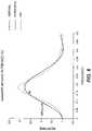
- FIG. 4shows the ratio of the green MTF to the blue MTF.
- FIG. 5shows an example of a least squares 7 ⁇ 7 convolution kernel that achieves an adequate approximation of the filter frequency response, as characterized by the ratio shown in FIG. 4 , that is required to equalize the sharpness of the blue channel to the green.
- FIG. 6shows the frequency response aim and actual filter frequency response of the filter characterized by the convolution kernel shown in FIG. 5 .
- FIG. 7shows before and after examples of an image subsection, with the technique of FIG. 1 applied according to the invention.
- FIG. 8shows before and after examples of the blue image plane of the image subsection shown in FIG. 7 , showing more obviously the blue intra-channel blur and its correction according to the invention.
- FIG. 9is a flow diagram showing details of a sharpness correction of a color dependent blur due to a longitudinal color aberration that is dependent upon a zoom lens position.
- FIG. 10is a block diagram of a digital camera having an arrangement for applying a channel dependent sharpening kernel to the blurred blue color channel in accordance with the present invention.
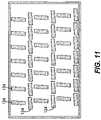
- FIG. 11is a diagram of an exemplary test target having multiple edges, which can be used to determine the system MTF.
- FIG. 12is a block diagram of a digital camera having a general arrangement for modifying a channel dependent sharpening kernel by applying a boost map to the sharpening kernel to account for a field dependent aberration.
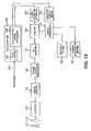
- FIG. 13is a block diagram of a digital capture and processing system having a digital camera for capturing a digital image that is subsequently processed by a host computer for applying a channel dependent correction to the blurred color channel in accordance with the present invention.
- FIGS. 14A and 14Bare perspective views of the front and back of a cell phone including a camera having an arrangement for applying a sharpening kernel to a blurred color channel in accordance with the present invention.
- One of the most important characteristics of an electronic imaging systemis the ability of its imaging device to capture fine detail found in an original scene. This ability to resolve detail is determined by a number of factors, including the performance of the optical system, the number of addressable photo elements in the optical imaging device, and the electrical circuits in the camera, which may include image compression and gamma correction functions.
- Different measurement methodscan provide different metrics to quantify the resolution of an imaging system, or a component of an imaging system, such as a lens.
- Resolution measurement metricsinclude resolving power, limiting resolution (at some specified contrast), modulation transfer function (MTF), and optical transfer function (OTF).
- the modulation transfer functionis the modulus of the optical transfer function, which is the two-dimensional Fourier transform of the point spread function of the imaging system under consideration.
- the OTFis a complex function whose modulus (MTF) has the value unity at zero spatial frequency.
- MTFmodulus
- the focus in this applicationis on use of the modulation transfer function to characterize the resolution of the capture and output devices, other metrics could be used, for example the OTF, spatial frequency response or depth of modulation level at various spatial frequencies.
- the modulation transfer functionis a graph (i.e., a set of discrete modulation factors) that represents the image contrast relative to the object contrast on the vertical axis over a range of spatial frequencies on the horizontal axis, where high frequency corresponds to small detail in an object. If it were possible to produce a facsimile image, the contrast of the image would be the same as the contrast of the object at all frequencies, and the MTF would be a straight horizontal line at a level of 1.0. In practice, the lines always slope downward to the right, since image contrast decreases as the spatial frequency increases.
- the MTFcan be determined for each component in an image-forming system or for combinations of components.
- the MTFcan also be determined for each color component being imaged, such as red, green and blue, in a given image plane in an image-forming system.
- the MTF for a systemcan be calculated by multiplying the modulation factors of the components at each spatial frequency. Since the MTF curves of all of the devices in a system are multiplied together point by point to provide the system MTF curve, the system curve is also a downwardly sloping function diminishing to zero resolution as the spatial frequency increases.
- This downwardly sloping characteristicresults in a gradual loss of contrast in the detail of the image as the detail becomes finer and finer.
- all optical deviceshave a non-ideal MTF response curve because of the finite size of the optical aperture associated therewith.
- the MTF curve of such optical devicesis normally a monotonically decreasing function such as a downwardly sloping diagonal line, i.e., a set of diminishing modulation factors, that intersects the spatial frequency axis at a point of frequency less than or equal to the diffraction limit—the point at which contrast or resolution diminishes to zero.
- a filtercan be designed with a transfer function to compensate for the diffraction effects of the finite size of the optical aperture of the system. If the filter curve is the inverse of the system MTF curve, the composite curve will be substantially flat out to the diffraction limit. The filter thus boosts the high spatial frequency contrast to compensate for the downwardly sloping characteristic of the system MTF.
- a chromatic aberrationresults from the fact that different wavelengths or colors of light are refracted by different amounts by an optical assembly.
- a longitudinal chromatic aberrationthe three components are brought to focus on different planes in the image space, which gives a color blurring effect.
- axial chromatic aberrationarises due to the focal length varying with wavelength (color).
- a further type of aberrationis a field dependent aberration, where some characteristic, such as the brightness, of an image pixel is changed in the image plane in proportion to its position in the field, such as its distance from the center of the image.
- a digital imagewhich is typically a two-dimensional array of red, green, and blue pixel values.
- a preferred embodimentis described with reference to a digital image of a given number of rows of pixels and a given number of lines of pixels.
- the value of a pixel of a digital image located at coordinates (x,y)shall herein comprise a triad of values [r(x,y), g(x,y), b(x,y)] respectively referring to the values of the red, green, and blue digital image channels at location (x,y).
- a digital imagecomprises a certain number of digital image channels.
- digital image channelIn the case of a digital image consisting of red, green and blue two-dimensional arrays, the image consists of exactly three channels.
- digital image channelwill be understood to encompass a single plane of a digital image. For example, if a digital image has red, green and blue components there are three channels.
- the present inventioncan be applied to one or more digital image channels. For purposes of the present invention each digital image channel may be considered to be a digital image.
- the present inventionrelates to a method for processing a digital image channel to compensate for MTF degradations in an optical system comprising one or more optical components, e.g., one or more lenses.
- the MTFcan be that of a single optical component which provides significant aberration of a digital image channel either during capture or processing, or it can be a group of optical components which provide significant aberration of a digital image channel either during capture or processing.
- the optical systemmay be a zoom lens system, where a group of optical components provide significant aberration of a digital image channel either during capture or processing dependent upon component lens positions during the zooming sequence.
- the MTF of such a zoom lenswill vary with zoom lens position, i.e., with zoom focal length.
- the present inventionmay be applied to a single digital image channel (for instance, the red channel, the green channel, or the blue channel), several digital image channels of a digital image, or all the digital image channels of the digital image. Also note that the present invention does not specify the source of the digital image.
- the digital imagemay, for example, be captured with a digital camera.
- the digital imagemay also be one of a motion picture sequence.
- the image possessing the aberrationmay, for example, be captured with a photographic film camera and the digital image is obtained by scanning or otherwise processing the film image.
- the digital imagemay be any actual scene processed by an optical system.
- FIG. 1there is shown a method for correcting a channel dependent color aberration in a digital image, where the digital image comprises a plurality of color channels.
- optics block 10an optical assembly comprising one or more lens components imparts one or more channel dependent aberrations to the original image. More specifically, a specific aberration is associated with one or more of the image channels, that is, as shown in FIG. 1 , channels a and b are substantially free of the aberration while channel c possesses the aberration.
- the aberrationis a longitudinal chromatic aberration that produces a blurred channel c.
- the three channels a, b and care captured in an image capture block 12 .
- the image captureis performed by a digital camera.
- the image capturemay be performed by scanning an original, such as a photographic film, where the original was itself captured by an optical assembly possessing the aberration. (Of course, the scanning optics may introduce its own aberrations.)
- an aim sharpness block 14one of the other color channels (other than the blurred color channel), in this case channel b, is used as an indication of an aim sharpness.
- the aim sharpnessis characterized by, or otherwise related to, the modulation transfer function (MTF) of the other color channel, that is, channel b, used as an indication of the aim sharpness.
- MTFmodulation transfer function
- This aim sharpnessis put to use in a sharpness adjustment block 16 to adjust the sharpness of the blurred color channel c, at least partially, toward the aim sharpness. Then the three channels a, b and c are combined, or otherwise processed, in an output block 18 to form the sharpness-corrected output image signal.
- a second color channele.g., channel a
- a second color channelcould also be a blurred color channel due to a channel dependent color aberration affecting that channel.
- an additional block(not shown) would be provided for adjusting the sharpness of the second blurred color channel a, at least partially, toward the aim sharpness obtained from the channel b.
- the blurred color channel cmay be adjusted toward the aim sharpness of the other color channel b and, additionally, enhanced toward an additional sharpness that is greater than the aim sharpness. Since the channel b is used as an indication of an aim sharpness, the aim sharpness may actually be greater than the actual sharpness of the other color channel b.
- the sharpness adjustment block 16may produce a sharpness that is greater than the aim sharpness, or produce a sharpness that is less than or substantially equal to the aim sharpness.
- the channel dependent color aberrationmay be a channel dependent degradation due to a color filter array used in the step of capturing the image, or a channel dependent degradation due to a field dependent aberration. In the latter case, the field dependent aberration may be a function of a radial distance from a center of the image.
- the sharpness adjustment block 16is there shown, in the preferred embodiment, to comprise an MTF determination block 30 for determining the MTF of the other color channel b used as an indication of the aim sharpness and an MTF determination block 32 for determining the MTF of the blurred color channel c.
- a ratio of the MTF of the other color channel b to the MTF of the blurred color channel cis determined in a ratio determination block 34 .
- the ratiois used in the filter generation block 36 to generate a filter, wherein the ratio is the aim frequency response of the filter.
- the filteris applied to the blurred color channel c in a filtering block 38 to adjust the sharpness of the blurred color channel, at least partially, toward the aim sharpness.
- the color channels a, b and care red, green and blue channels, respectively, where the color channel b used as an indication of the aim sharpness is the green channel and the blurred color channel c is the blue channel.
- the filtering in the filtering block 38may be done in the frequency domain or the spatial domain.
- the MTF of the blurred color channel c and the MTF of the other color channel bmay be determined from an image measurement or from lens data.
- the method described in this applicationprovides in-camera (or, as will be explained, in-host) correction of one or more color channels primarily for the purpose of removing fringing and intra-channel blur.
- Longitudinal colorresults from image focus being wavelength dependant. So, for example, the blue channel may focus optimally behind the best focus position for the red and green channels. This example produces blur in the blue channel, due to the plane of focus being behind the image sensor for the blue channel.
- the blur associated with this misfocus of the blue channelcan be corrected by applying a filter to that plane of image data, which equalizes the sharpness of the blurred blue channel to an aim sharpness.
- the aim sharpnessis the MTF of the green channel and thus the aim frequency response of the filter is the ratio of the MTF of the green channel to the MTF of the blue channel.
- FIG. 3shows the MTF of the three color channels, where the respective responses of the channels are plotted against the frequency, measured in cycles/sample (from 0 to 0.5 cycles/sample).
- FIG. 4shows the ratio of the green MTF to the blue MTF. This ratio is also the aim of the filter applied to the reduced MTF blue channel to sharpen it to the level of the green.
- a convolution kernelis developed with a sufficient number of taps such that it achieves an adequate approximation of the filter frequency response required to equalize the sharpness of the blue channel to the green.
- any well-known two-dimensional digital filter design techniquemay be used to develop the convolution kernel.
- a common way to specify the desired characteristics of a digital filteris to do so in the frequency domain, i.e. by an MTF. If we assume that we are not interested in modifying the phase characteristics of the image, then a linear-phase finite impulse response (FIR) is needed.
- One well-known way to design a filteris by the window method (W. K. Pratt, Digital Image Processing , Wiley, pg. 291-296, 1978). The steps are as follows:
- FIG. 5shows an example of the values comprising a least squares 7 ⁇ 7 convolution kernel that achieves an adequate approximation of the filter frequency response, as characterized by the ratio shown in FIG. 4 , that is required to equalize the sharpness of the blue channel to the green.
- FIG. 6shows the frequency response aim and actual filter frequency response of the filter characterized according to FIGS. 3-5 .
- FIG. 7shows before and after examples of an image subsection with the technique of the invention applied.
- FIG. 8shows before and after examples of only the blue image plane and shows more obviously the blue intra-channel blur and its correction in accordance with the invention.
- the channel dependent aberrationis a longitudinal color aberration especially in the blue color record or file of a digital image, where the digital image comprises red, green and blue color channels.
- the color channelsare imaged (block 10 ) by an optical system having the aberration, where the blue color channel is a blurred color channel due in particular to the longitudinal color aberration affecting that channel.
- the method according to one typical application of the inventionmay be characterized by the following steps:
- ratio determination block 34(c) computing a ratio of the MTF of the other color channel to the MTF of the blue color channel (ratio determination block 34 );
- steps (a)-(d)may be performed in relation to manufacture, testing or other pre-use preparation of a digital camera and steps (e)-(f) are then performed in the digital camera itself to modify the image files.
- the actual filter data necessary to adjust the sharpness of the blurred color channelwould be stored in the camera itself, or, e.g., in a memory appliance (e.g., a removable memory chip or card) that can be inserted, attached or otherwise communicated (e.g., by radio frequency (rf) or infrared (ir) communication) to the camera.
- a memory appliancee.g., a removable memory chip or card
- steps (a)-(d)may be performed in relation to manufacture, testing or other pre-use preparation of a digital camera
- step (e)is performed in the digital camera
- steps (f)is performed in a host computer that accesses the images captured by the digital camera.
- the cameramay attach metadata to the image files indicating what kind of correction filter should be applied to the affected digital color channel by the host computer.
- the host computermay take a variety of forms, such as a personal computer in, e.g., the user's home, a digital picture kiosk in, e.g., a retail photo establishment, an on-line photo processing web site, a control computer in a retail or commercial photofinishing establishment, or the like.
- the filter data needed to process the affected blurred color channel(s)could be resident with the host computer (especially, e.g., where a limited number of filter configurations may apply to a wide universe of applications) or the filter data may be obtained from some other source, such as on-line via downloading from some dedicated data source, such as, e.g., a manufacturer's data base pertaining to the camera.
- the optical system(block 10 ) is a zoom system with a plurality of zoom lens positions and the MTF of the optical zoom system for the color channels varies for different lens positions. Consequently, as shown in an MTF determination block 50 in FIG. 9 , the MTF of the other color channel b used as an indication of the aim sharpness and the MTF of the blurred color channel c is determined for a plurality of lens positions.
- an MTF correctionis computed in a ratio computation block 52 as a ratio of the MTF of the other color channel b to the MTF of the blue color channel c for (at least some of) the lens positions.
- an MTF correctionis interpolated in an interpolation block 54 from the computed corrections as a function of lens position for the intervening lens positions.
- a filteris generated in a filter generation block 56 that varies its filtering effect with lens position.
- the filteris applied in a filtering block 58 to the blue color channel c to equalize the sharpness of the blue color channel, at least partially, to the aim sharpness dependent upon the zoom lens position.
- the filtering effect of the filtering block 58is changed dependent upon the zoom lens focal length.
- the digital cameraincludes an image sensor 112 which includes a two-dimensional array of photosites corresponding to picture elements (pixels) of the image.
- the image sensor 112can be a conventional charge-coupled device (CCD) using either well known interline transfer or frame transfer techniques, or a complementary metal oxide semiconductor (CMOS) imager.
- CCDcharge-coupled device
- CMOScomplementary metal oxide semiconductor
- An imageis captured under the control of a microprocessor 114 which causes a shutter 116 to open and an image of a subject 117 is applied by a lens 118 to the image sensor 112 .
- analog image chargeis produced in respective photosites.
- the charge information produced by the image sensor 112is applied to an analog signal processor 120 .
- the analog signal processor 120controls the read-out clocking of the image sensor 112 and converts the charge information to analog image signals corresponding to respective picture elements.
- the analog image signals from the analog signal processor 120are applied to an analog to digital (A/D) converter 122 , which produces a digital image signal from the analog input signal for each picture element.
- the captured digital image signalsare stored in memory 124 .
- the image captured by the image sensor 112has channel dependent blur which is a function of the system MTF of at least one of the color channels, in this case the blue color channel.
- a filteris created which comprises a plurality of values that are an inverse function of an aim sharpness as represented by another of the color channels, such as the green color channel. These values can be applied as a stored sharpening function, such as a stored sharpening kernel 130 .
- the microprocessor 114receives the stored sharpening kernel 130 , and applies the sharpening kernel 130 to the digital image, and a modified image 132 is produced which is sharpened and corrected for channel dependent blur.
- Implementation of the sharpening kernel 130can take the form of a direct convolution in a manner well known to those skilled in the art.
- the camera manufacturerfirst characterizes the MTF of the green and blue channels of the image created by the electronic camera, and determines the ratio of the two MTF functions, as hereinbefore explained.
- the local value of the system MTF for an electronic camerais a function of the MTF of the optical components (i.e., the lens and the blur filter), and as well as MTF degradation associated with the electronic acquisition and processing components, such as image sensor charge transfer inefficiencies.
- the system MTFis a function of the MTF of the optical components, as well as blur caused by mispositioning of the film relative to the focal plane.
- a preferred method of measuring the system MTFis to utilize an oversampled edge technique to measure the MTF at various locations in the image.
- An example of such an oversampled edge techniqueis described in ISO 12233—“Photography—Electronic Still Picture Cameras—Resolution Measurements” (ISO/TC42-WG18).
- ISO 12233“Photography—Electronic Still Picture Cameras—Resolution Measurements”
- FIG. 11shows an example of a test target having multiple edges 134 . Each edge 134 can be used to determine the MTF of the imaging system at the location of the edge 134 .
- image blur aberrationsother than a channel dependent blur due to a longitudinal color aberration.
- the image formed at the focal planei.e., on a photosensitive film or on a photosensitive array (e.g., a CCD or CMOS sensor)
- the image formed at the focal planeis typically blurred as a function of proximity to the optical axis.
- the further away from the center of the imagethe more the image is blurred.
- the resultant imagetherefore has an MTF which is a function of radial distance from the center of the image.
- an imagecan also possess blur due to mechanisms like image sensor charge transfer inefficiency.
- Sensor based mechanismswill, in general, have different symmetry than the described lens mechanism, but are also correctable. In either case, such blur is referred to as a field dependent or position dependent blur.
- imagesare sharpened and corrected for position dependent blur.
- a sharpening functionoperates upon, and sharpens, signals corresponding to a selected number of pixels in an image.
- a plurality of valuesare generated which are a function of the position dependent blur in the image. These values are then used to modify the sharpening function so that after the modified sharpening function is applied to the image, a sharpened image will be provided which has been corrected for the position dependent blur.
- the present inventionextends this field dependent sharpening concept to individual color channels, where the blur aberration is also a channel dependent degradation imparted to the already-existing field dependent aberration, that is, the position dependent blur is a function of the channel as well as the position in the image. Typically, for example, a greater position dependent blur will be observed in the blue channel than in the red and green channels.
- FIG. 12is a block diagram of a digital camera having a general arrangement for providing a channel dependent sharpening kernel according to the present invention, and modifying the kernel by applying a boost map to the sharpening kernel in accordance with the teaching of the aforementioned U.S. Pat. No. 6,628,329. Because many of the components in FIG. 12 are identical to the components shown in FIG. 10 , reference should be made to FIG. 10 and its corresponding description for an explanation of such components. In this embodiment, the image captured by the image sensor 112 has position dependent blur which is a function of the system MTF. In accordance with the aforementioned U.S. Pat. No.
- a boost map 128is created which is a plurality of values which are a function of the position dependent blur of the captured image, and which can be applied to the stored sharpening kernel 130 .
- the microprocessor 114receives the stored boost map 128 and the stored sharpening kernel 130 , and modifies the stored sharpening kernel 130 in response to the boost map 128 .
- the boost map 128varies the boost strength of the stored sharpening kernel 130 so as to spatially compensate for the local value of the system MTF and correct for the position dependent blur of the captured image.
- the microprocessor 114applies the modified sharpening kernel 130 to the digital image, and a modified image 132 is produced which is sharpened and corrected for channel dependent, as well as position dependent, blur.
- the camera manufacturerfirst characterizes the MTF of a film camera or an electronic camera and the associated processing components, and determines the local value of the system MTF.
- the local value of the system MTF for an electronic camerais a function of the MTF of the optical components (i.e., the lens and the blur filter), and as well as MTF degradation associated with the electronic acquisition and processing components, such as image sensor charge transfer inefficiencies.
- the system MTFis a function of the MTF of the optical components, as well as blur caused by mispositioning of the film relative to the focal plane.
- a preferred method of measuring the system MTFis to utilize an oversampled edge technique to measure the MTF at various locations in the image.
- the camera manufacturerthen develops the boost map 128 as an array of position dependent gain factors (boost values) stored in a two-dimensional look-up table which scale the coefficients of the sharpening kernel 130 on a pixel-by-pixel basis in response to the local value of the system MTF in order to correct for the position dependent blur of the captured image.
- the boost map 128For each pixel of the captured image, the boost map 128 includes a corresponding boost value.
- the stored boost map 128may have a similar number of array values as the image sensor 112 , or may have a reduced number of values (for example, 1/16 as many rows and 1/16 as many columns) which are repeated or bilinearly interpolated, for example, to provide the boost factors for each pixel.
- the boost map 128can be defined by a two-dimensional polynomial equation representing the gain required to obtain desired local values of the system MTF. Since the MTF is a slowly varying function of position, a two-dimensional polynomial equation will generally suffice rather than a memory intensive multi-dimensional lookup table.
- FIG. 13is a block diagram of a digital capture and processing system having a digital camera for capturing a digital image that is subsequently processed by a host computer for applying a channel dependent correction to the blurred color channel in accordance with the present invention. Because many of the components in FIG. 13 are identical to the components shown in FIG. 10 , reference should be made to FIG. 10 and its corresponding description for an explanation of such components.
- the digital cameraincludes a host computer interface 135 for connecting with a host computer 136 .
- the host computer interface 135may take a variety of forms, such as (without limitation) a cable connection (e.g., FIREWIRE or USB), a memory card interface (e.g., a PCMCIA card connection), a radio frequency or infra-red connection, and the like.
- the host computer 136which interfaces with the digital camera and processes the captured image, includes (a) a data store 138 for storing the channel dependent filter, such as the kernal coefficients shown in FIG. 5 and a digital processor 140 (typically implementing software algorithms) for applying the filter to the blurred color channel to adjust the sharpness of the blurred color channel, at least partially, toward the aim sharpness.
- the channel-corrected output image 132is then provided by the host computer 136 .
- the host computermay take a variety of forms, such as a personal computer in, e.g., the user's home, a digital picture kiosk in, e.g., a retail photo establishment, an on-line photo processing web site, a control computer in a retail or commercial photofinishing establishment, or the like.
- the cameramay attach metadata to the image files indicating what kind of correction filter should be applied to the affected digital color channel by the host computer 136 .
- the microprocessor 114applies metadata from a metadata store 142 indicating the type of camera and/or the type of filtering that should be applied to the image files.
- the filter data needed to process the affected blurred color channel(s)could be resident with the host computer 136 (especially, e.g., where a limited number of filter configurations may apply to a wide universe of applications) or the filter data may be obtained from some other source, such as on-line (signified by internet connection 144 ) via downloading from some dedicated data source, such as, e.g., a manufacturer's data base pertaining to the camera.
- such an internet connectioncould be made directly to the digital camera shown in FIG. 10 to provide the appropriate sharpening kernel, rather than having the kernel stored in the camera.
- a cell phone 200includes a phone stage comprising a microphone 202 for capturing the voice of a caller, related electronics (not shown) for processing the voice signals of the caller and the person called, and a speaker 204 for reproducing the voice of the one called.
- a keypad 206is provided for entering phone numbers and image capture commands, and a (LCD) display 208 for showing phone-related data and for reproducing images captured by the phone or received over the cellular network.
- a cellular image capture assembly 210(comprising a lens 211 and an image sensor (not shown)) connected via an image processor 212 to a cellular processing stage comprising a cellular processor 214 and a modem 216 .
- the cellular processor 214receives and processes the image data from the image processor 212 and the voice data captured by the microphone 202 , and transfers the image and voice data to the cellular modem 216 .
- the cellular modem 216converts the digital image and voice data into the appropriate format for transmission by the antenna 218 to a cellular network.
- the image captured by the image capture assembly 210has channel dependent blur which is a function of the system MTF of at least one of the color channels, such as the blue color channel.
- a filteris created which comprises a plurality of values that are an inverse function of an aim sharpness as represented by another of the color channels, such as the green color channel. These values can be applied as a stored sharpening function, such as a stored sharpening kernel 220 , as described in connection with FIG. 10 .
- the image processor 212receives the stored sharpening kernel 220 , and applies the sharpening kernel 220 to the digital image, and a modified image is produced which is sharpened and corrected for channel dependent blur.
- the cell phone 200may include a host computer interface (not shown) for connecting with a host computer (also not shown) for processing the image and correcting for channel dependent color aberrations, as described in connection with FIG. 13 .
- the host computermay instead be available over the cellular network, and the cell phone 200 may transmit the uncorrected image over the cellular network to the host computer, where the image is corrected for channel dependent color aberrations.
- the corrected imagemay then be returned to the cell phone 200 for display on the display 208 or otherwise communicated to other recipients.
- Practicing the invention described in this disclosurebegins with measuring the MTF of each of the color channels in a digital image. This can be accomplished by using tools such as the aforementioned ISO 12233—Resolution in a Digital Camera Standard SFR measurement tool. This tool uses the image edge features from the ISO-12233 Resolution Target. The user selects regions of interest, which span the light and dark regions of the edge. The utility will compute the spatial frequency response (MTF) of the system using the edge feature. Rather than forming the luminance MTF by weighing each color channel in some fashion for the purpose of reporting the resolution or MTF of the imaging system, in this invention each channel's MTF is measured and used in the development of a filter. Other MTF determining methods could also be employed.
- MTFspatial frequency response
- optical design software packagestypically specify the wavelength dependant MTFs.
- the Green MTF valuesfrom 0 to 0.5 cycles/sample, are divided by the Blue MTF values across the same frequency range. The result of this frequency by frequency division, is the aim frequency response of the needed filter.
- This filteris then applied to the blue channel image, thus equalizing the blue channel's MTF to that of the green channel's MTF.
- Filtering of the blue image planemay be done in either the frequency or spatial domain.
- a convolution in the spatial domainis less computationally complex than frequency plane transformation and manipulation, especially for smaller convolution kernels.
- FIG. 5kernel values
- FIG. 6kernel and aim frequency responses
- the kernel sizecan be smaller than 7 ⁇ 7.
- the color filter array (CFA) of an imagermay be a specific pattern, such as the well-known Bayer CFA pattern.
- the Bayer CFA samplingpossesses an inherent reduced red and blue (relative to the green) MTF characteristic.
- Some CFA interpolation reconstruction (de-mosaicking) algorithmsmake use the higher MTF green channel in the reconstruction of the red and blue planes, but frequently the red and blue channels are less sharp than the green.
- This inventioncan also repair images suffering from reduced MTF due to the CFA sampling of the focal plane. This scenario requires two filtering operations, one on the red and one on the blue channel.
Landscapes
- Engineering & Computer Science (AREA)
- Physics & Mathematics (AREA)
- General Physics & Mathematics (AREA)
- Theoretical Computer Science (AREA)
- Multimedia (AREA)
- Signal Processing (AREA)
- Image Processing (AREA)
- Color Television Image Signal Generators (AREA)
Abstract
Description
y=x{circle around (x)}h,
where x and y are the input and output sampled image arrays, h is the array of filter coefficients, and {circle around (x)} indicates the discrete convolution operation. A common way to specify the desired characteristics of a digital filter is to do so in the frequency domain, i.e. by an MTF. If we assume that we are not interested in modifying the phase characteristics of the image, then a linear-phase finite impulse response (FIR) is needed. One well-known way to design a filter is by the window method (W. K. Pratt,Digital Image Processing, Wiley, pg. 291-296, 1978). The steps are as follows:
- 1. Form a two-dimensional array and populate it with the desired (sampled) frequency response of the filter (low-pass, high-pass, etc.)
- 2. Compute the inverse discrete Fourier transform (using the fast Fourier transform algorithm).
- 3. Truncate the resulting array of (real) coefficients, or apply a window function (e.g., Hamming Window) that also truncates the array, to the desired filter size, e.g., (5×5 or 7×7).
- 4. The values in this array are often rescaled so that, e.g., the sum of all elements are equal to 1.0, if needed.
- 5. The resulting array of coefficients, h, are convolved with an input image array, x, resulting in an output filtered image array, y.
In general, the larger the filter size, the more closely its actual MTF will match the desired response.
Claims (27)
Priority Applications (1)
| Application Number | Priority Date | Filing Date | Title |
|---|---|---|---|
| US11/114,841US7683950B2 (en) | 2005-04-26 | 2005-04-26 | Method and apparatus for correcting a channel dependent color aberration in a digital image |
Applications Claiming Priority (1)
| Application Number | Priority Date | Filing Date | Title |
|---|---|---|---|
| US11/114,841US7683950B2 (en) | 2005-04-26 | 2005-04-26 | Method and apparatus for correcting a channel dependent color aberration in a digital image |
Publications (2)
| Publication Number | Publication Date |
|---|---|
| US20060239549A1 US20060239549A1 (en) | 2006-10-26 |
| US7683950B2true US7683950B2 (en) | 2010-03-23 |
Family
ID=37186960
Family Applications (1)
| Application Number | Title | Priority Date | Filing Date |
|---|---|---|---|
| US11/114,841Expired - Fee RelatedUS7683950B2 (en) | 2005-04-26 | 2005-04-26 | Method and apparatus for correcting a channel dependent color aberration in a digital image |
Country Status (1)
| Country | Link |
|---|---|
| US (1) | US7683950B2 (en) |
Cited By (8)
| Publication number | Priority date | Publication date | Assignee | Title |
|---|---|---|---|---|
| US20080193034A1 (en)* | 2007-02-08 | 2008-08-14 | Yu Wang | Deconvolution method using neighboring-pixel-optical-transfer-function in fourier domain |
| US20090231420A1 (en)* | 2008-03-14 | 2009-09-17 | Tetsuya Kokufu | Image pickup apparatus and image combining method of image pickup apparatus |
| US20100194902A1 (en)* | 2009-02-05 | 2010-08-05 | National Chung Cheng University | Method for high dynamic range imaging |
| US20110090378A1 (en)* | 2009-10-16 | 2011-04-21 | Sen Wang | Image deblurring using panchromatic pixels |
| US20110149103A1 (en)* | 2009-12-17 | 2011-06-23 | Canon Kabushiki Kaisha | Image processing apparatus and image pickup apparatus using same |
| US20130278726A1 (en)* | 2011-01-14 | 2013-10-24 | Sony Corporation | Imaging system using a lens unit with longitudinal chromatic aberrations and method of operating |
| US10430932B2 (en)* | 2016-09-15 | 2019-10-01 | Axis Ab | Method and an arrangement for pseudo coloring of a digital image |
| US20200372615A1 (en)* | 2019-05-24 | 2020-11-26 | Canon Kabushiki Kaisha | Image processing apparatus, lens apparatus, and image processing method |
Families Citing this family (108)
| Publication number | Priority date | Publication date | Assignee | Title |
|---|---|---|---|---|
| FR2827459B1 (en)* | 2001-07-12 | 2004-10-29 | Poseidon | METHOD AND SYSTEM FOR PROVIDING IMAGE PROCESSING SOFTWARE FORMAT INFORMATION RELATED TO THE CHARACTERISTICS OF IMAGE CAPTURE APPARATUS AND / OR IMAGE RENDERING MEANS |
| US20060093234A1 (en)* | 2004-11-04 | 2006-05-04 | Silverstein D A | Reduction of blur in multi-channel images |
| US7580586B1 (en)* | 2005-04-19 | 2009-08-25 | Lockheed Martin Corporation | Enhanced recovery of low spatial frequency spectral information in a Fizeau Fourier transform spectrometer |
| US8233710B2 (en)* | 2005-07-14 | 2012-07-31 | Nikon Corporation | Image processing device and image processing method |
| JP4712631B2 (en)* | 2005-07-28 | 2011-06-29 | 京セラ株式会社 | Imaging device |
| JP2007304525A (en)* | 2006-05-15 | 2007-11-22 | Ricoh Co Ltd | Image input apparatus, electronic apparatus, and image input method |
| US8630031B1 (en)* | 2006-06-27 | 2014-01-14 | Marvell International Ltd. | Color adjustment for a scanned image |
| DE102007001010A1 (en)* | 2007-01-02 | 2008-07-10 | Fraunhofer-Gesellschaft zur Förderung der angewandten Forschung e.V. | Method and image acquisition system for achromatized image acquisition of objects |
| WO2008086037A2 (en)* | 2007-01-10 | 2008-07-17 | Flextronics International Usa Inc. | Color filter array interpolation |
| US7830428B2 (en)* | 2007-04-12 | 2010-11-09 | Aptina Imaging Corporation | Method, apparatus and system providing green-green imbalance compensation |
| US7876363B2 (en)* | 2007-04-19 | 2011-01-25 | Aptina Imaging Corporation | Methods, systems and apparatuses for high-quality green imbalance compensation in images |
| JP4912238B2 (en)* | 2007-07-09 | 2012-04-11 | キヤノン株式会社 | Imaging device and interchangeable lens device |
| EP2206334A2 (en)* | 2007-09-28 | 2010-07-14 | OCE-Technologies B.V. | Method, apparatus and computer program for adaptive compensation of a mtf |
| US8525914B2 (en)* | 2007-10-25 | 2013-09-03 | DigitalOptics Corporation Europe Limited | Imaging system with multi-state zoom and associated methods |
| US8149319B2 (en)* | 2007-12-03 | 2012-04-03 | Ricoh Co., Ltd. | End-to-end design of electro-optic imaging systems for color-correlated objects |
| JP5132401B2 (en)* | 2008-04-16 | 2013-01-30 | キヤノン株式会社 | Image processing apparatus and image processing method |
| US8866920B2 (en) | 2008-05-20 | 2014-10-21 | Pelican Imaging Corporation | Capturing and processing of images using monolithic camera array with heterogeneous imagers |
| DK3876510T3 (en) | 2008-05-20 | 2024-11-11 | Adeia Imaging Llc | CAPTURE AND PROCESSING OF IMAGES USING MONOLITHIC CAMERA ARRAY WITH HETEROGENEOUS IMAGES |
| US11792538B2 (en) | 2008-05-20 | 2023-10-17 | Adeia Imaging Llc | Capturing and processing of images including occlusions focused on an image sensor by a lens stack array |
| US8135233B2 (en)* | 2008-05-22 | 2012-03-13 | Aptina Imaging Corporation | Method and apparatus for the restoration of degraded multi-channel images |
| US8477206B2 (en)* | 2008-09-30 | 2013-07-02 | Canon Kabushiki Kaisha | Image processing apparatus and image processing method for performing image restoration using restoration filter |
| JP4942216B2 (en)* | 2008-09-30 | 2012-05-30 | キヤノン株式会社 | Image processing method, image processing apparatus, imaging apparatus, and program |
| JP4986965B2 (en)* | 2008-09-30 | 2012-07-25 | キヤノン株式会社 | Image processing method, image processing apparatus, image processing program, and imaging apparatus |
| JP5374217B2 (en)* | 2009-04-22 | 2013-12-25 | キヤノン株式会社 | Image processing apparatus and method |
| US8328365B2 (en) | 2009-04-30 | 2012-12-11 | Hewlett-Packard Development Company, L.P. | Mesh for mapping domains based on regularized fiducial marks |
| JP5409112B2 (en)* | 2009-05-21 | 2014-02-05 | キヤノン株式会社 | Image processing apparatus and method |
| JP5317891B2 (en)* | 2009-08-19 | 2013-10-16 | キヤノン株式会社 | Image processing apparatus, image processing method, and computer program |
| US8248511B2 (en)* | 2009-09-30 | 2012-08-21 | Ricoh Co., Ltd. | Dual-mode extended depth-of-field imaging systems |
| EP2502115A4 (en) | 2009-11-20 | 2013-11-06 | Pelican Imaging Corp | CAPTURE AND IMAGE PROCESSING USING A MONOLITHIC CAMERAS NETWORK EQUIPPED WITH HETEROGENEOUS IMAGERS |
| JP5366775B2 (en)* | 2009-12-01 | 2013-12-11 | キヤノン株式会社 | Imaging apparatus and image processing method |
| CN102109753A (en)* | 2009-12-25 | 2011-06-29 | 鸿富锦精密工业(深圳)有限公司 | Automatic lens detecting method |
| US8330825B2 (en)* | 2010-02-22 | 2012-12-11 | Eastman Kodak Company | Zoom lens system characterization for image sharpening |
| JP5528173B2 (en) | 2010-03-31 | 2014-06-25 | キヤノン株式会社 | Image processing apparatus, imaging apparatus, and image processing program |
| US8928793B2 (en) | 2010-05-12 | 2015-01-06 | Pelican Imaging Corporation | Imager array interfaces |
| US8878950B2 (en) | 2010-12-14 | 2014-11-04 | Pelican Imaging Corporation | Systems and methods for synthesizing high resolution images using super-resolution processes |
| US8861852B2 (en)* | 2011-05-09 | 2014-10-14 | Canon Kabushiki Kaisha | Image processing method for image restoration, image processing apparatus and image pickup apparatus |
| EP2708019B1 (en) | 2011-05-11 | 2019-10-16 | FotoNation Limited | Systems and methods for transmitting and receiving array camera image data |
| CN102158730B (en)* | 2011-05-26 | 2014-04-02 | 威盛电子股份有限公司 | Image processing system and method |
| CN102158731B (en)* | 2011-05-26 | 2014-03-12 | 威盛电子股份有限公司 | Image processing system and method |
| US20130265459A1 (en) | 2011-06-28 | 2013-10-10 | Pelican Imaging Corporation | Optical arrangements for use with an array camera |
| KR20140045458A (en) | 2011-06-28 | 2014-04-16 | 펠리칸 이매징 코포레이션 | Optical arrangements for use with an array camera |
| JP5264968B2 (en)* | 2011-08-08 | 2013-08-14 | キヤノン株式会社 | Image processing apparatus, image processing method, imaging apparatus, and image processing program |
| JP5414752B2 (en) | 2011-08-08 | 2014-02-12 | キヤノン株式会社 | Image processing method, image processing apparatus, imaging apparatus, and image processing program |
| JP5917048B2 (en)* | 2011-08-26 | 2016-05-11 | キヤノン株式会社 | Image processing apparatus, image processing method, and program |
| US20130070060A1 (en) | 2011-09-19 | 2013-03-21 | Pelican Imaging Corporation | Systems and methods for determining depth from multiple views of a scene that include aliasing using hypothesized fusion |
| CN104081414B (en) | 2011-09-28 | 2017-08-01 | Fotonation开曼有限公司 | Systems and methods for encoding and decoding light field image files |
| EP2817955B1 (en) | 2012-02-21 | 2018-04-11 | FotoNation Cayman Limited | Systems and methods for the manipulation of captured light field image data |
| US9754357B2 (en)* | 2012-03-23 | 2017-09-05 | Panasonic Intellectual Property Corporation Of America | Image processing device, stereoscoopic device, integrated circuit, and program for determining depth of object in real space generating histogram from image obtained by filming real space and performing smoothing of histogram |
| US9210392B2 (en) | 2012-05-01 | 2015-12-08 | Pelican Imaging Coporation | Camera modules patterned with pi filter groups |
| JP2015534734A (en) | 2012-06-28 | 2015-12-03 | ペリカン イメージング コーポレイション | System and method for detecting defective camera arrays, optical arrays, and sensors |
| US20140002674A1 (en) | 2012-06-30 | 2014-01-02 | Pelican Imaging Corporation | Systems and Methods for Manufacturing Camera Modules Using Active Alignment of Lens Stack Arrays and Sensors |
| PL4296963T3 (en) | 2012-08-21 | 2025-04-28 | Adeia Imaging Llc | Method for depth detection in images captured using array cameras |
| WO2014032020A2 (en) | 2012-08-23 | 2014-02-27 | Pelican Imaging Corporation | Feature based high resolution motion estimation from low resolution images captured using an array source |
| US9214013B2 (en) | 2012-09-14 | 2015-12-15 | Pelican Imaging Corporation | Systems and methods for correcting user identified artifacts in light field images |
| EP4307659A1 (en) | 2012-09-28 | 2024-01-17 | Adeia Imaging LLC | Generating images from light fields utilizing virtual viewpoints |
| WO2014078443A1 (en) | 2012-11-13 | 2014-05-22 | Pelican Imaging Corporation | Systems and methods for array camera focal plane control |
| US9462164B2 (en) | 2013-02-21 | 2016-10-04 | Pelican Imaging Corporation | Systems and methods for generating compressed light field representation data using captured light fields, array geometry, and parallax information |
| US9374512B2 (en) | 2013-02-24 | 2016-06-21 | Pelican Imaging Corporation | Thin form factor computational array cameras and modular array cameras |
| US9774789B2 (en) | 2013-03-08 | 2017-09-26 | Fotonation Cayman Limited | Systems and methods for high dynamic range imaging using array cameras |
| US8866912B2 (en) | 2013-03-10 | 2014-10-21 | Pelican Imaging Corporation | System and methods for calibration of an array camera using a single captured image |
| US9521416B1 (en) | 2013-03-11 | 2016-12-13 | Kip Peli P1 Lp | Systems and methods for image data compression |
| US9888194B2 (en) | 2013-03-13 | 2018-02-06 | Fotonation Cayman Limited | Array camera architecture implementing quantum film image sensors |
| US9124831B2 (en) | 2013-03-13 | 2015-09-01 | Pelican Imaging Corporation | System and methods for calibration of an array camera |
| US9106784B2 (en) | 2013-03-13 | 2015-08-11 | Pelican Imaging Corporation | Systems and methods for controlling aliasing in images captured by an array camera for use in super-resolution processing |
| WO2014165244A1 (en) | 2013-03-13 | 2014-10-09 | Pelican Imaging Corporation | Systems and methods for synthesizing images from image data captured by an array camera using restricted depth of field depth maps in which depth estimation precision varies |
| US9578259B2 (en) | 2013-03-14 | 2017-02-21 | Fotonation Cayman Limited | Systems and methods for reducing motion blur in images or video in ultra low light with array cameras |
| WO2014153098A1 (en) | 2013-03-14 | 2014-09-25 | Pelican Imaging Corporation | Photmetric normalization in array cameras |
| US9438888B2 (en) | 2013-03-15 | 2016-09-06 | Pelican Imaging Corporation | Systems and methods for stereo imaging with camera arrays |
| WO2014150856A1 (en) | 2013-03-15 | 2014-09-25 | Pelican Imaging Corporation | Array camera implementing quantum dot color filters |
| US9633442B2 (en) | 2013-03-15 | 2017-04-25 | Fotonation Cayman Limited | Array cameras including an array camera module augmented with a separate camera |
| US9497429B2 (en) | 2013-03-15 | 2016-11-15 | Pelican Imaging Corporation | Extended color processing on pelican array cameras |
| US9445003B1 (en) | 2013-03-15 | 2016-09-13 | Pelican Imaging Corporation | Systems and methods for synthesizing high resolution images using image deconvolution based on motion and depth information |
| US10122993B2 (en) | 2013-03-15 | 2018-11-06 | Fotonation Limited | Autofocus system for a conventional camera that uses depth information from an array camera |
| US9898856B2 (en) | 2013-09-27 | 2018-02-20 | Fotonation Cayman Limited | Systems and methods for depth-assisted perspective distortion correction |
| US9264592B2 (en) | 2013-11-07 | 2016-02-16 | Pelican Imaging Corporation | Array camera modules incorporating independently aligned lens stacks |
| US10119808B2 (en) | 2013-11-18 | 2018-11-06 | Fotonation Limited | Systems and methods for estimating depth from projected texture using camera arrays |
| WO2015081279A1 (en) | 2013-11-26 | 2015-06-04 | Pelican Imaging Corporation | Array camera configurations incorporating multiple constituent array cameras |
| US10089740B2 (en) | 2014-03-07 | 2018-10-02 | Fotonation Limited | System and methods for depth regularization and semiautomatic interactive matting using RGB-D images |
| US10506914B2 (en)* | 2014-03-17 | 2019-12-17 | Intuitive Surgical Operations, Inc. | Surgical system including a non-white light general illuminator |
| US9247117B2 (en) | 2014-04-07 | 2016-01-26 | Pelican Imaging Corporation | Systems and methods for correcting for warpage of a sensor array in an array camera module by introducing warpage into a focal plane of a lens stack array |
| US9521319B2 (en) | 2014-06-18 | 2016-12-13 | Pelican Imaging Corporation | Array cameras and array camera modules including spectral filters disposed outside of a constituent image sensor |
| JP6263461B2 (en)* | 2014-09-26 | 2018-01-17 | 日立オートモティブシステムズ株式会社 | Imaging device |
| JP2017531976A (en) | 2014-09-29 | 2017-10-26 | フォトネイション ケイマン リミテッド | System and method for dynamically calibrating an array camera |
| WO2016052004A1 (en)* | 2014-09-30 | 2016-04-07 | 富士フイルム株式会社 | Image processing device, filter acquisition device, image processing method, filter acquisition method, program, and recording medium |
| CN107079094B (en)* | 2014-09-30 | 2018-07-13 | 富士胶片株式会社 | Image processing apparatus, image processing method and recording medium |
| KR102190233B1 (en) | 2014-10-06 | 2020-12-11 | 삼성전자주식회사 | Apparatus and method for processing image thereof |
| US9942474B2 (en) | 2015-04-17 | 2018-04-10 | Fotonation Cayman Limited | Systems and methods for performing high speed video capture and depth estimation using array cameras |
| US10178381B2 (en) | 2015-07-14 | 2019-01-08 | Microsoft Technology Licensing, Llc | Depth-spatial frequency-response assessment |
| US20170061586A1 (en)* | 2015-08-28 | 2017-03-02 | Nokia Technologies Oy | Method, apparatus and computer program product for motion deblurring of image frames |
| EP3203437A1 (en)* | 2016-02-05 | 2017-08-09 | Thomson Licensing | Method and apparatus for locally sharpening a video image using a spatial indication of blurring |
| US10482618B2 (en) | 2017-08-21 | 2019-11-19 | Fotonation Limited | Systems and methods for hybrid depth regularization |
| US11442266B1 (en)* | 2019-09-09 | 2022-09-13 | Apple Inc. | Method and device for correcting chromatic aberration in multiple bands |
| US11270110B2 (en) | 2019-09-17 | 2022-03-08 | Boston Polarimetrics, Inc. | Systems and methods for surface modeling using polarization cues |
| WO2021071992A1 (en) | 2019-10-07 | 2021-04-15 | Boston Polarimetrics, Inc. | Systems and methods for augmentation of sensor systems and imaging systems with polarization |
| DE112020005932T5 (en) | 2019-11-30 | 2023-01-05 | Boston Polarimetrics, Inc. | SYSTEMS AND METHODS FOR SEGMENTATION OF TRANSPARENT OBJECTS USING POLARIZATION CHARACTERISTICS |
| EP4081933A4 (en) | 2020-01-29 | 2024-03-20 | Intrinsic Innovation LLC | Systems and methods for characterizing object pose detection and measurement systems |
| US11797863B2 (en) | 2020-01-30 | 2023-10-24 | Intrinsic Innovation Llc | Systems and methods for synthesizing data for training statistical models on different imaging modalities including polarized images |
| US11953700B2 (en) | 2020-05-27 | 2024-04-09 | Intrinsic Innovation Llc | Multi-aperture polarization optical systems using beam splitters |
| US12069227B2 (en) | 2021-03-10 | 2024-08-20 | Intrinsic Innovation Llc | Multi-modal and multi-spectral stereo camera arrays |
| US12020455B2 (en) | 2021-03-10 | 2024-06-25 | Intrinsic Innovation Llc | Systems and methods for high dynamic range image reconstruction |
| US11954886B2 (en) | 2021-04-15 | 2024-04-09 | Intrinsic Innovation Llc | Systems and methods for six-degree of freedom pose estimation of deformable objects |
| US11290658B1 (en) | 2021-04-15 | 2022-03-29 | Boston Polarimetrics, Inc. | Systems and methods for camera exposure control |
| US12067746B2 (en) | 2021-05-07 | 2024-08-20 | Intrinsic Innovation Llc | Systems and methods for using computer vision to pick up small objects |
| US12175741B2 (en) | 2021-06-22 | 2024-12-24 | Intrinsic Innovation Llc | Systems and methods for a vision guided end effector |
| US12340538B2 (en) | 2021-06-25 | 2025-06-24 | Intrinsic Innovation Llc | Systems and methods for generating and using visual datasets for training computer vision models |
| US12172310B2 (en) | 2021-06-29 | 2024-12-24 | Intrinsic Innovation Llc | Systems and methods for picking objects using 3-D geometry and segmentation |
| US11689813B2 (en) | 2021-07-01 | 2023-06-27 | Intrinsic Innovation Llc | Systems and methods for high dynamic range imaging using crossed polarizers |
| US12293535B2 (en) | 2021-08-03 | 2025-05-06 | Intrinsic Innovation Llc | Systems and methods for training pose estimators in computer vision |
Citations (34)
| Publication number | Priority date | Publication date | Assignee | Title |
|---|---|---|---|---|
| US4418358A (en) | 1980-11-07 | 1983-11-29 | Robert Bosch Gmbh | Method and system to correct color errors in color television signals generated by scanning a film |
| US4536885A (en) | 1983-03-03 | 1985-08-20 | Hazeltine Corporation | Distortion correcting AM stereo receiver with non-flat AGC |
| US4616252A (en) | 1984-07-16 | 1986-10-07 | Rca Corporation | Sampled color difference signal processing system having a quadrature distortion reduction differentiator |
| US4677465A (en) | 1985-11-01 | 1987-06-30 | Eastman Kodak Company | Digital color image processing method with shape correction of histograms used to produce color reproduction functions |
| US4937720A (en) | 1989-10-13 | 1990-06-26 | Sundstrand Corporation | PWM inverter circuit analytically compensating for DC link distortion |
| US4961139A (en) | 1988-06-30 | 1990-10-02 | Hewlett-Packard Company | Data base management system for real-time applications |
| US4970593A (en) | 1989-08-28 | 1990-11-13 | Sperry Marine Inc. | Video image enhancement utilizing a two-dimensional digital aperture correction filter |
| US5010401A (en) | 1988-08-11 | 1991-04-23 | Mitsubishi Denki Kabushiki Kaisha | Picture coding and decoding apparatus using vector quantization |
| US5047968A (en) | 1988-03-04 | 1991-09-10 | University Of Massachusetts Medical Center | Iterative image restoration device |
| US5291286A (en) | 1988-02-29 | 1994-03-01 | Mitsubishi Denki Kabushiki Kaisha | Multimedia data transmission system |
| US5293258A (en) | 1990-12-31 | 1994-03-08 | International Business Machines Corporation | Automatic correction for color printing |
| US5461440A (en) | 1993-02-10 | 1995-10-24 | Olympus Optical Co., Ltd. | Photographing image correction system |
| US5561611A (en) | 1994-10-04 | 1996-10-01 | Noran Instruments, Inc. | Method and apparatus for signal restoration without knowledge of the impulse response function of the signal acquisition system |
| US5565931A (en) | 1994-10-31 | 1996-10-15 | Vivo Software. Inc. | Method and apparatus for applying gamma predistortion to a color image signal |
| US5696850A (en) | 1995-12-21 | 1997-12-09 | Eastman Kodak Company | Automatic image sharpening in an electronic imaging system |
| US5721694A (en) | 1994-05-10 | 1998-02-24 | Aura System, Inc. | Non-linear deterministic stochastic filtering method and system |
| US5729631A (en) | 1993-11-30 | 1998-03-17 | Polaroid Corporation | Image noise reduction system using a wiener variant filter in a pyramid image representation |
| WO1998031142A1 (en) | 1997-01-06 | 1998-07-16 | Applied Science Fiction, Inc. | Defect channel nulling |
| US5801854A (en) | 1995-02-14 | 1998-09-01 | Canon Information Systems Research Australia Pty Ltd | Color conversion method |
| US5900952A (en) | 1996-10-15 | 1999-05-04 | Xerox Corporation | System for converting color image signals having high-frequency components from RGB to CMY color spaces |
| US5939246A (en) | 1997-03-17 | 1999-08-17 | Eastman Kodak Company | Color photographic silver halide negative imaging material and process |
| US6009209A (en) | 1997-06-27 | 1999-12-28 | Microsoft Corporation | Automated removal of red eye effect from a digital image |
| US6055340A (en)* | 1997-02-28 | 2000-04-25 | Fuji Photo Film Co., Ltd. | Method and apparatus for processing digital images to suppress their noise and enhancing their sharpness |
| US20020097439A1 (en) | 2001-01-23 | 2002-07-25 | Oak Technology, Inc. | Edge detection and sharpening process for an image |
| US6628329B1 (en) | 1998-08-26 | 2003-09-30 | Eastman Kodak Company | Correction of position dependent blur in a digital image |
| US20040047514A1 (en) | 2002-09-05 | 2004-03-11 | Eastman Kodak Company | Method for sharpening a digital image |
| US6728003B1 (en) | 2000-04-04 | 2004-04-27 | Eastman Kodak Company | Method of compensating for MTF in a digital image channel |
| US20040081364A1 (en)* | 2002-10-19 | 2004-04-29 | Eastman Kodak Company | Image processing |
| US20040218803A1 (en) | 2001-07-12 | 2004-11-04 | Laurent Chanas | Method and system for producing formatted information related to the defects of at least one appliance of a chain, in particular related to blurring |
| US20040218071A1 (en) | 2001-07-12 | 2004-11-04 | Benoit Chauville | Method and system for correcting the chromatic aberrations of a color image produced by means of an optical system |
| US20040240750A1 (en) | 2001-07-12 | 2004-12-02 | Benoit Chauville | Method and system for producing formatted data related to geometric distortions |
| US20040247201A1 (en) | 2003-03-05 | 2004-12-09 | Shinichi Arazaki | Chromatic aberration correction apparatus, chromatic aberration correction method, and chromatic aberration correction program |
| US20060093234A1 (en)* | 2004-11-04 | 2006-05-04 | Silverstein D A | Reduction of blur in multi-channel images |
| US20060181620A1 (en)* | 2005-02-11 | 2006-08-17 | Kimbell Benjamin D | Decreasing aliasing in electronic images |
Family Cites Families (1)
| Publication number | Priority date | Publication date | Assignee | Title |
|---|---|---|---|---|
| US5641440A (en)* | 1995-07-26 | 1997-06-24 | The United States Of America As Represented By The Secretary Of The Navy | Sintering aids for producing BaO.Al2 O3.2SiO2 and SrO.Al.sub. O3.2SiO2 ceramic materials |
- 2005
- 2005-04-26USUS11/114,841patent/US7683950B2/ennot_activeExpired - Fee Related
Patent Citations (35)
| Publication number | Priority date | Publication date | Assignee | Title |
|---|---|---|---|---|
| US4418358A (en) | 1980-11-07 | 1983-11-29 | Robert Bosch Gmbh | Method and system to correct color errors in color television signals generated by scanning a film |
| US4536885A (en) | 1983-03-03 | 1985-08-20 | Hazeltine Corporation | Distortion correcting AM stereo receiver with non-flat AGC |
| US4616252A (en) | 1984-07-16 | 1986-10-07 | Rca Corporation | Sampled color difference signal processing system having a quadrature distortion reduction differentiator |
| US4677465A (en) | 1985-11-01 | 1987-06-30 | Eastman Kodak Company | Digital color image processing method with shape correction of histograms used to produce color reproduction functions |
| US5291286A (en) | 1988-02-29 | 1994-03-01 | Mitsubishi Denki Kabushiki Kaisha | Multimedia data transmission system |
| US5047968A (en) | 1988-03-04 | 1991-09-10 | University Of Massachusetts Medical Center | Iterative image restoration device |
| US4961139A (en) | 1988-06-30 | 1990-10-02 | Hewlett-Packard Company | Data base management system for real-time applications |
| US5010401A (en) | 1988-08-11 | 1991-04-23 | Mitsubishi Denki Kabushiki Kaisha | Picture coding and decoding apparatus using vector quantization |
| US4970593A (en) | 1989-08-28 | 1990-11-13 | Sperry Marine Inc. | Video image enhancement utilizing a two-dimensional digital aperture correction filter |
| US4937720A (en) | 1989-10-13 | 1990-06-26 | Sundstrand Corporation | PWM inverter circuit analytically compensating for DC link distortion |
| US5293258A (en) | 1990-12-31 | 1994-03-08 | International Business Machines Corporation | Automatic correction for color printing |
| US5461440A (en) | 1993-02-10 | 1995-10-24 | Olympus Optical Co., Ltd. | Photographing image correction system |
| US5729631A (en) | 1993-11-30 | 1998-03-17 | Polaroid Corporation | Image noise reduction system using a wiener variant filter in a pyramid image representation |
| US5721694A (en) | 1994-05-10 | 1998-02-24 | Aura System, Inc. | Non-linear deterministic stochastic filtering method and system |
| US5561611A (en) | 1994-10-04 | 1996-10-01 | Noran Instruments, Inc. | Method and apparatus for signal restoration without knowledge of the impulse response function of the signal acquisition system |
| US5565931A (en) | 1994-10-31 | 1996-10-15 | Vivo Software. Inc. | Method and apparatus for applying gamma predistortion to a color image signal |
| US5801854A (en) | 1995-02-14 | 1998-09-01 | Canon Information Systems Research Australia Pty Ltd | Color conversion method |
| US5696850A (en) | 1995-12-21 | 1997-12-09 | Eastman Kodak Company | Automatic image sharpening in an electronic imaging system |
| US5900952A (en) | 1996-10-15 | 1999-05-04 | Xerox Corporation | System for converting color image signals having high-frequency components from RGB to CMY color spaces |
| WO1998031142A1 (en) | 1997-01-06 | 1998-07-16 | Applied Science Fiction, Inc. | Defect channel nulling |
| US6055340A (en)* | 1997-02-28 | 2000-04-25 | Fuji Photo Film Co., Ltd. | Method and apparatus for processing digital images to suppress their noise and enhancing their sharpness |
| US5939246A (en) | 1997-03-17 | 1999-08-17 | Eastman Kodak Company | Color photographic silver halide negative imaging material and process |
| US6009209A (en) | 1997-06-27 | 1999-12-28 | Microsoft Corporation | Automated removal of red eye effect from a digital image |
| US6628329B1 (en) | 1998-08-26 | 2003-09-30 | Eastman Kodak Company | Correction of position dependent blur in a digital image |
| US6728003B1 (en) | 2000-04-04 | 2004-04-27 | Eastman Kodak Company | Method of compensating for MTF in a digital image channel |
| US20020097439A1 (en) | 2001-01-23 | 2002-07-25 | Oak Technology, Inc. | Edge detection and sharpening process for an image |
| US20040218803A1 (en) | 2001-07-12 | 2004-11-04 | Laurent Chanas | Method and system for producing formatted information related to the defects of at least one appliance of a chain, in particular related to blurring |
| US20040218071A1 (en) | 2001-07-12 | 2004-11-04 | Benoit Chauville | Method and system for correcting the chromatic aberrations of a color image produced by means of an optical system |
| US20040240750A1 (en) | 2001-07-12 | 2004-12-02 | Benoit Chauville | Method and system for producing formatted data related to geometric distortions |
| US20040247195A1 (en) | 2001-07-12 | 2004-12-09 | Benoit Chauville | Method and system for calculating a transformed image from a digital image |
| US20040047514A1 (en) | 2002-09-05 | 2004-03-11 | Eastman Kodak Company | Method for sharpening a digital image |
| US20040081364A1 (en)* | 2002-10-19 | 2004-04-29 | Eastman Kodak Company | Image processing |
| US20040247201A1 (en) | 2003-03-05 | 2004-12-09 | Shinichi Arazaki | Chromatic aberration correction apparatus, chromatic aberration correction method, and chromatic aberration correction program |
| US20060093234A1 (en)* | 2004-11-04 | 2006-05-04 | Silverstein D A | Reduction of blur in multi-channel images |
| US20060181620A1 (en)* | 2005-02-11 | 2006-08-17 | Kimbell Benjamin D | Decreasing aliasing in electronic images |
Non-Patent Citations (7)
| Title |
|---|
| XP000225283, Aggelos K. Katsaggelos et al., "A Regularized Iterative Image Restoration Algorithm", IEEE Transactions on Signal Processing, vol. 39, No. 4, Apr. 1991, pp. 914-929. |
| XP000280610, J.N. Lin et al., "2-D Adaptive Volterra Filter For 2-D Nonlinear Channel Equalization and Image Restoration", 8030 Electronic Letters, vol. 28, No. 2, Jan. 16, 1992, Stevenage, Herts, pp. 180-182. |
| XP000443551, M. Doyle et al., "Adaptive Fourier Threshold Filtering: A Method to Reduce Noise and Incoherent Artifacts in High Resolution Cardiac Images", 8306 Magnetic Resonance in Medicine 31 May 1999, No. 5, Baltimore, Maryland, US, pp. 546-550. |
| XP000780652, Til Aach et al., "Anisotropic Spectral Magnitude Estimation Filters For Noise Reduction and Image Enhancement", 0-7803-3258-X96, 1996, IEEE, Philips GmbH Research Laboratories, Weisshausstr.2, D-52066 Aachen, Germany, pp. 335-338. |
| XP000896196, Mei Yu et al., "New Adaptive Vector Filter Based on Noise Estimate", IEICE Transactions Fundamentals vol. E-82A No. 6, Jun. 1999, Paper, Sepcial Section of Papers Selected from ITC-CSCC 98, pp. 911-919. |
| XP002146062, B Aiazzi et al., "A Robust Method For Parameter Estimation of Signal-Dependent Noise Models in Digital Images", 0-7803-4137-Jun. 1997, IEEE, pp. 601-604. |
| XP002146454, Rangaraj M. Rangayyan et al., "Adaptive-neighborhood Filtering of Images Corrupted By Signal-Dependent Noise", 0003-6935/98/204477-11, Jul. 10, 1998, vol. 37, No. 20, Applied Optics, 1998 Optical Society of America, Department of Electrical and Computer Engineering, University of Calgary, 2500 University Drive, N.W. Calgary, Alberta T2N 1N4, Canada, pp. 4477-4487. |
Cited By (15)
| Publication number | Priority date | Publication date | Assignee | Title |
|---|---|---|---|---|
| US20080193034A1 (en)* | 2007-02-08 | 2008-08-14 | Yu Wang | Deconvolution method using neighboring-pixel-optical-transfer-function in fourier domain |
| US7912307B2 (en)* | 2007-02-08 | 2011-03-22 | Yu Wang | Deconvolution method using neighboring-pixel-optical-transfer-function in fourier domain |
| US20090231420A1 (en)* | 2008-03-14 | 2009-09-17 | Tetsuya Kokufu | Image pickup apparatus and image combining method of image pickup apparatus |
| US8405713B2 (en)* | 2008-03-14 | 2013-03-26 | Olympus Imaging Corp. | Image pickup apparatus and image combining method of image pickup apparatus |
| US20100194902A1 (en)* | 2009-02-05 | 2010-08-05 | National Chung Cheng University | Method for high dynamic range imaging |
| US8208048B2 (en)* | 2009-02-05 | 2012-06-26 | National Chung Cheng University | Method for high dynamic range imaging |
| US8203615B2 (en)* | 2009-10-16 | 2012-06-19 | Eastman Kodak Company | Image deblurring using panchromatic pixels |
| US20110090378A1 (en)* | 2009-10-16 | 2011-04-21 | Sen Wang | Image deblurring using panchromatic pixels |
| US20110149103A1 (en)* | 2009-12-17 | 2011-06-23 | Canon Kabushiki Kaisha | Image processing apparatus and image pickup apparatus using same |
| US8659672B2 (en)* | 2009-12-17 | 2014-02-25 | Canon Kabushiki Kaisha | Image processing apparatus and image pickup apparatus using same |
| US20130278726A1 (en)* | 2011-01-14 | 2013-10-24 | Sony Corporation | Imaging system using a lens unit with longitudinal chromatic aberrations and method of operating |
| US9979941B2 (en)* | 2011-01-14 | 2018-05-22 | Sony Corporation | Imaging system using a lens unit with longitudinal chromatic aberrations and method of operating |
| US10430932B2 (en)* | 2016-09-15 | 2019-10-01 | Axis Ab | Method and an arrangement for pseudo coloring of a digital image |
| US20200372615A1 (en)* | 2019-05-24 | 2020-11-26 | Canon Kabushiki Kaisha | Image processing apparatus, lens apparatus, and image processing method |
| US11599973B2 (en)* | 2019-05-24 | 2023-03-07 | Canon Kabushiki Kaisha | Image processing apparatus, lens apparatus, and image processing method for sharpening processing |
Also Published As
| Publication number | Publication date |
|---|---|
| US20060239549A1 (en) | 2006-10-26 |
Similar Documents
| Publication | Publication Date | Title |
|---|---|---|
| US7683950B2 (en) | Method and apparatus for correcting a channel dependent color aberration in a digital image | |
| JP5284537B2 (en) | Image processing apparatus, image processing method, image processing program, and imaging apparatus using the same | |
| CN102822863B (en) | The image pick up equipment of image processing equipment and this image processing equipment of use | |
| US8659672B2 (en) | Image processing apparatus and image pickup apparatus using same | |
| CN103259976B (en) | Image processing equipment, picture pick-up device and image processing method | |
| US6628329B1 (en) | Correction of position dependent blur in a digital image | |
| US7529424B2 (en) | Correction of optical distortion by image processing | |
| CN104995911B (en) | Image processing device, image capture device, filter generating device, image restoration method, and program | |
| JP5546229B2 (en) | Image processing method, image processing apparatus, imaging apparatus, and image processing program | |
| US9866750B2 (en) | Image processing device, imaging device, image processing method, and image processing program | |
| JP2020144489A (en) | Image processing method, image processing device, program, method of producing trained model, and image processing system | |
| US20060013479A1 (en) | Restoration of color components in an image model | |
| US9892495B2 (en) | Image processing device, imaging device, image processing method, and image processing program | |
| WO2011121763A1 (en) | Image processing apparatus and image capturing apparatus using same | |
| JP5514042B2 (en) | Imaging module, image signal processing method, and imaging apparatus | |
| JP5479187B2 (en) | Image processing apparatus and imaging apparatus using the same | |
| JP7504629B2 (en) | IMAGE PROCESSING METHOD, IMAGE PROCESSING APPARATUS, IMAGE PROCESSING PROGRAM, AND STORAGE MEDIUM | |
| US8237829B2 (en) | Image processing device, image processing method, and imaging apparatus | |
| Sato | Image-processing algorithms | |
| GB2460241A (en) | Correction of optical lateral chromatic aberration | |
| US8736722B2 (en) | Enhanced image capture sharpening | |
| JP3476843B2 (en) | Edge enhancement circuit | |
| JP2012156714A (en) | Program, image processing device, image processing method, and imaging device | |
| EP4332834A1 (en) | Method and camera device for generating a moiré-corrected image file | |
| WO2011121761A1 (en) | Image processing apparatus and image capturing apparatus using same |
Legal Events
| Date | Code | Title | Description |
|---|---|---|---|
| AS | Assignment | Owner name:EASTMAN KODAK COMPANY,NEW YORK Free format text:ASSIGNMENT OF ASSIGNORS INTEREST;ASSIGNORS:KELLY, SEAN C.;BURNS, PETER D.;REEL/FRAME:016625/0716 Effective date:20050526 Owner name:EASTMAN KODAK COMPANY, NEW YORK Free format text:ASSIGNMENT OF ASSIGNORS INTEREST;ASSIGNORS:KELLY, SEAN C.;BURNS, PETER D.;REEL/FRAME:016625/0716 Effective date:20050526 | |
| FEPP | Fee payment procedure | Free format text:PAYOR NUMBER ASSIGNED (ORIGINAL EVENT CODE: ASPN); ENTITY STATUS OF PATENT OWNER: LARGE ENTITY | |
| AS | Assignment | Owner name:CITICORP NORTH AMERICA, INC., AS AGENT, NEW YORK Free format text:SECURITY INTEREST;ASSIGNORS:EASTMAN KODAK COMPANY;PAKON, INC.;REEL/FRAME:028201/0420 Effective date:20120215 | |
| FEPP | Fee payment procedure | Free format text:PAYER NUMBER DE-ASSIGNED (ORIGINAL EVENT CODE: RMPN); ENTITY STATUS OF PATENT OWNER: LARGE ENTITY | |
| FEPP | Fee payment procedure | Free format text:PAYOR NUMBER ASSIGNED (ORIGINAL EVENT CODE: ASPN); ENTITY STATUS OF PATENT OWNER: LARGE ENTITY Free format text:PAYER NUMBER DE-ASSIGNED (ORIGINAL EVENT CODE: RMPN); ENTITY STATUS OF PATENT OWNER: LARGE ENTITY | |
| AS | Assignment | Owner name:KODAK (NEAR EAST), INC., NEW YORK Free format text:PATENT RELEASE;ASSIGNORS:CITICORP NORTH AMERICA, INC.;WILMINGTON TRUST, NATIONAL ASSOCIATION;REEL/FRAME:029913/0001 Effective date:20130201 Owner name:KODAK AMERICAS, LTD., NEW YORK Free format text:PATENT RELEASE;ASSIGNORS:CITICORP NORTH AMERICA, INC.;WILMINGTON TRUST, NATIONAL ASSOCIATION;REEL/FRAME:029913/0001 Effective date:20130201 Owner name:QUALEX INC., NORTH CAROLINA Free format text:PATENT RELEASE;ASSIGNORS:CITICORP NORTH AMERICA, INC.;WILMINGTON TRUST, NATIONAL ASSOCIATION;REEL/FRAME:029913/0001 Effective date:20130201 Owner name:KODAK PORTUGUESA LIMITED, NEW YORK Free format text:PATENT RELEASE;ASSIGNORS:CITICORP NORTH AMERICA, INC.;WILMINGTON TRUST, NATIONAL ASSOCIATION;REEL/FRAME:029913/0001 Effective date:20130201 Owner name:LASER-PACIFIC MEDIA CORPORATION, NEW YORK Free format text:PATENT RELEASE;ASSIGNORS:CITICORP NORTH AMERICA, INC.;WILMINGTON TRUST, NATIONAL ASSOCIATION;REEL/FRAME:029913/0001 Effective date:20130201 Owner name:KODAK IMAGING NETWORK, INC., CALIFORNIA Free format text:PATENT RELEASE;ASSIGNORS:CITICORP NORTH AMERICA, INC.;WILMINGTON TRUST, NATIONAL ASSOCIATION;REEL/FRAME:029913/0001 Effective date:20130201 Owner name:FPC INC., CALIFORNIA Free format text:PATENT RELEASE;ASSIGNORS:CITICORP NORTH AMERICA, INC.;WILMINGTON TRUST, NATIONAL ASSOCIATION;REEL/FRAME:029913/0001 Effective date:20130201 Owner name:KODAK PHILIPPINES, LTD., NEW YORK Free format text:PATENT RELEASE;ASSIGNORS:CITICORP NORTH AMERICA, INC.;WILMINGTON TRUST, NATIONAL ASSOCIATION;REEL/FRAME:029913/0001 Effective date:20130201 Owner name:FAR EAST DEVELOPMENT LTD., NEW YORK Free format text:PATENT RELEASE;ASSIGNORS:CITICORP NORTH AMERICA, INC.;WILMINGTON TRUST, NATIONAL ASSOCIATION;REEL/FRAME:029913/0001 Effective date:20130201 Owner name:KODAK AVIATION LEASING LLC, NEW YORK Free format text:PATENT RELEASE;ASSIGNORS:CITICORP NORTH AMERICA, INC.;WILMINGTON TRUST, NATIONAL ASSOCIATION;REEL/FRAME:029913/0001 Effective date:20130201 Owner name:EASTMAN KODAK COMPANY, NEW YORK Free format text:PATENT RELEASE;ASSIGNORS:CITICORP NORTH AMERICA, INC.;WILMINGTON TRUST, NATIONAL ASSOCIATION;REEL/FRAME:029913/0001 Effective date:20130201 Owner name:KODAK REALTY, INC., NEW YORK Free format text:PATENT RELEASE;ASSIGNORS:CITICORP NORTH AMERICA, INC.;WILMINGTON TRUST, NATIONAL ASSOCIATION;REEL/FRAME:029913/0001 Effective date:20130201 Owner name:EASTMAN KODAK INTERNATIONAL CAPITAL COMPANY, INC., Free format text:PATENT RELEASE;ASSIGNORS:CITICORP NORTH AMERICA, INC.;WILMINGTON TRUST, NATIONAL ASSOCIATION;REEL/FRAME:029913/0001 Effective date:20130201 Owner name:NPEC INC., NEW YORK Free format text:PATENT RELEASE;ASSIGNORS:CITICORP NORTH AMERICA, INC.;WILMINGTON TRUST, NATIONAL ASSOCIATION;REEL/FRAME:029913/0001 Effective date:20130201 Owner name:PAKON, INC., INDIANA Free format text:PATENT RELEASE;ASSIGNORS:CITICORP NORTH AMERICA, INC.;WILMINGTON TRUST, NATIONAL ASSOCIATION;REEL/FRAME:029913/0001 Effective date:20130201 Owner name:CREO MANUFACTURING AMERICA LLC, WYOMING Free format text:PATENT RELEASE;ASSIGNORS:CITICORP NORTH AMERICA, INC.;WILMINGTON TRUST, NATIONAL ASSOCIATION;REEL/FRAME:029913/0001 Effective date:20130201 | |
| AS | Assignment | Owner name:APPLE INC., CALIFORNIA Free format text:ASSIGNMENT OF ASSIGNORS INTEREST;ASSIGNOR:EASTMAN KODAK COMPANY;REEL/FRAME:029939/0508 Effective date:20130211 | |
| REMI | Maintenance fee reminder mailed | ||
| FEPP | Fee payment procedure | Free format text:PETITION RELATED TO MAINTENANCE FEES FILED (ORIGINAL EVENT CODE: PMFP); ENTITY STATUS OF PATENT OWNER: LARGE ENTITY Free format text:PETITION RELATED TO MAINTENANCE FEES GRANTED (ORIGINAL EVENT CODE: PMFG); ENTITY STATUS OF PATENT OWNER: LARGE ENTITY | |
| LAPS | Lapse for failure to pay maintenance fees | ||
| REIN | Reinstatement after maintenance fee payment confirmed | ||
| PRDP | Patent reinstated due to the acceptance of a late maintenance fee | Effective date:20140502 | |
| FPAY | Fee payment | Year of fee payment:4 | |
| SULP | Surcharge for late payment | ||
| FP | Lapsed due to failure to pay maintenance fee | Effective date:20140323 | |
| FEPP | Fee payment procedure | Free format text:MAINTENANCE FEE REMINDER MAILED (ORIGINAL EVENT CODE: REM.) | |
| LAPS | Lapse for failure to pay maintenance fees | Free format text:PATENT EXPIRED FOR FAILURE TO PAY MAINTENANCE FEES (ORIGINAL EVENT CODE: EXP.) | |
| STCH | Information on status: patent discontinuation | Free format text:PATENT EXPIRED DUE TO NONPAYMENT OF MAINTENANCE FEES UNDER 37 CFR 1.362 | |
| FP | Lapsed due to failure to pay maintenance fee | Effective date:20180323 |