US7683864B2 - LED driving apparatus with temperature compensation function - Google Patents
LED driving apparatus with temperature compensation functionDownload PDFInfo
- Publication number
- US7683864B2 US7683864B2US11/657,083US65708307AUS7683864B2US 7683864 B2US7683864 B2US 7683864B2US 65708307 AUS65708307 AUS 65708307AUS 7683864 B2US7683864 B2US 7683864B2
- Authority
- US
- United States
- Prior art keywords
- voltage
- inversion
- amplification unit
- light emitting
- reference voltage
- Prior art date
- Legal status (The legal status is an assumption and is not a legal conclusion. Google has not performed a legal analysis and makes no representation as to the accuracy of the status listed.)
- Active, expires
Links
Images


Classifications
- G—PHYSICS
- G09—EDUCATION; CRYPTOGRAPHY; DISPLAY; ADVERTISING; SEALS
- G09G—ARRANGEMENTS OR CIRCUITS FOR CONTROL OF INDICATING DEVICES USING STATIC MEANS TO PRESENT VARIABLE INFORMATION
- G09G3/00—Control arrangements or circuits, of interest only in connection with visual indicators other than cathode-ray tubes
- G09G3/20—Control arrangements or circuits, of interest only in connection with visual indicators other than cathode-ray tubes for presentation of an assembly of a number of characters, e.g. a page, by composing the assembly by combination of individual elements arranged in a matrix no fixed position being assigned to or needed to be assigned to the individual characters or partial characters
- G09G3/34—Control arrangements or circuits, of interest only in connection with visual indicators other than cathode-ray tubes for presentation of an assembly of a number of characters, e.g. a page, by composing the assembly by combination of individual elements arranged in a matrix no fixed position being assigned to or needed to be assigned to the individual characters or partial characters by control of light from an independent source
- G09G3/3406—Control of illumination source
- E—FIXED CONSTRUCTIONS
- E03—WATER SUPPLY; SEWERAGE
- E03B—INSTALLATIONS OR METHODS FOR OBTAINING, COLLECTING, OR DISTRIBUTING WATER
- E03B7/00—Water main or service pipe systems
- E03B7/09—Component parts or accessories
- E03B7/095—Component holders or housings, e.g. boundary boxes
- H—ELECTRICITY
- H05—ELECTRIC TECHNIQUES NOT OTHERWISE PROVIDED FOR
- H05B—ELECTRIC HEATING; ELECTRIC LIGHT SOURCES NOT OTHERWISE PROVIDED FOR; CIRCUIT ARRANGEMENTS FOR ELECTRIC LIGHT SOURCES, IN GENERAL
- H05B45/00—Circuit arrangements for operating light-emitting diodes [LED]
- H05B45/10—Controlling the intensity of the light
- H05B45/18—Controlling the intensity of the light using temperature feedback
- E—FIXED CONSTRUCTIONS
- E03—WATER SUPPLY; SEWERAGE
- E03B—INSTALLATIONS OR METHODS FOR OBTAINING, COLLECTING, OR DISTRIBUTING WATER
- E03B7/00—Water main or service pipe systems
- E03B7/09—Component parts or accessories
- E03B7/10—Devices preventing bursting of pipes by freezing
- E03B7/12—Devices preventing bursting of pipes by freezing by preventing freezing
- G—PHYSICS
- G09—EDUCATION; CRYPTOGRAPHY; DISPLAY; ADVERTISING; SEALS
- G09G—ARRANGEMENTS OR CIRCUITS FOR CONTROL OF INDICATING DEVICES USING STATIC MEANS TO PRESENT VARIABLE INFORMATION
- G09G2320/00—Control of display operating conditions
- G09G2320/04—Maintaining the quality of display appearance
- G09G2320/041—Temperature compensation
Definitions
- the present inventionrelates to a Light Emitting Diode (LED) driving apparatus applicable to a Liquid Crystal Display (LCD) backlight unit, and more particularly, to an LED driving apparatus having a temperature compensation function, which can compensate luminance variation according to temperature changes by using a forward voltage of an LED light source so that the forward voltage of the LED light source is controlled in association with a target current value of ambient temperature, without having to use an optical sensor or temperature sensor or memory or judging means such as CPU, thereby decreasing an installation space, saving manufacturing costs and promoting design flexibility.
- LEDLight Emitting Diode
- LCDLiquid Crystal Display
- LEDs used in an LCD backlight or lighting instrumenttheir junction resistance is generally variable according to temperature. Therefore, an LED drive apparatus is required to have temperature compensation means.
- FIG. 1is a block diagram of a conventional LED driving unit.
- the conventional LED driving unitincludes a control unit 10 for performing operation control via supply voltage Vcc and feedback voltage Vfd, a driving unit 20 for supplying the supply voltage Vcc in response to the control of the control unit 10 , a LED light source 30 including a plurality of LEDs which emit light in response to the supply voltage of the driver 20 , an optical sensor 40 for detecting light emitted from the LEDs and a feedback circuit 50 for supplying the feedback voltage Vfd in response to a detection signal by the optical sensor 40 to the control unit 10 .
- the driving unit 20is composed of a transistor Q 1 that adjusts the supply voltage in response to a supply control signal from the control unit 10 .
- the feedback circuit 50compares the detection signal by the optical sensor 40 with a reference signal to supply the feedback voltage Vfd, corresponding to an error signal of the comparison result, to the control unit 10 .
- the control unit 10varies the supply voltage in response to the feedback voltage Vfd to control the operation of the LEDs.
- Such a conventional LED driving apparatususes an automatic power control process.
- control unitcontrols the operation in response to the feedback voltage in such a fashion of increasing the collector current of the transistor Q 1 of the driving unit so that light quantity can be maintained constantly.
- the conventional LED driving apparatususes an expensive photo-sensor or optical sensor for directly monitoring the light quantity of the LEDs.
- the expensive optical sensorbecomes burdensome for a low cost assembly product, which is provided as a set.
- monitoring necessary for respective wavelengthsdisadvantageously increases cost burden.
- the present inventionhas been made to solve the foregoing problems of the prior art and therefore an aspect of certain embodiments of the present invention is to provide an LED driving apparatus applicable to an LCD backlight unit, and more particularly, to an LED driving apparatus having a temperature compensation function, which can compensate luminance variation according to temperature changes by using a forward voltage of an LED light source so that the forward voltage of the LED light source is controlled in association with a target current value of ambient temperature, without having to use an optical sensor or temperature sensor or memory or judging means such as CPU, thereby decreasing an installation space, saving manufacturing costs and promoting design flexibility.
- the inventionprovides an LED driving apparatus comprising: a reference voltage generator for generating a first reference voltage; a non-inversion amplification unit for performing non-inversion amplification to a difference voltage between the first reference voltage and a forward voltage with a preset gain; a driving unit for adjusting a supply voltage in response to the voltage from the non-inversion amplification unit to supply the adjusted supply voltage to a light source having light emitting diodes; and a forward voltage detector for detecting the forward voltage at an anode of the light emitting diodes of the light source to supply the forward voltage to the non-inversion amplification unit, whereby temperature change is compensated.
- the reference voltage generatoris adapted to adjust the first reference voltage in response to user selection.
- the non-conversion amplification unitcomprises a non-inversion operation amplifier, which includes: an inversion input terminal connected to a first reference voltage terminal connected from the reference voltage generator; and a non-inversion input terminal connected to a forward voltage terminal of the forward voltage detector.
- a non-inversion operation amplifierwhich includes: an inversion input terminal connected to a first reference voltage terminal connected from the reference voltage generator; and a non-inversion input terminal connected to a forward voltage terminal of the forward voltage detector.
- the inversion input terminal of the non-inversion amplification unitmay be connected to the first reference voltage terminal via a first resistor and to an output of the non-inversion operation amplifier via a second resistor, and the non-inversion input terminal of the non-inversion amplification unit is connected to the forward voltage terminal via a third resistor.
- the light emitting diode driving apparatusmay further include an on/off switch for switching connection between the non-inversion input terminal of the non-inversion amplification unit and the supply voltage terminal to turn on/off the light source and a current limiter for supplies the second reference voltage in place of the output voltage to the driving unit thereby limiting the supply voltage of the driving unit if the output voltage of the non-inversion amplification unit is lower than a preset second reference voltage.
- the current limiterincludes: a comparator for comparing the output voltage of the non-inversion amplification unit with the second reference voltage; and a switch for selecting a larger one of the output voltage of the non-inversion amplification unit and the second reference voltage in response to the comparison result of the comparator.
- the forward voltage detectorincludes a buffer operation amplifier for detecting the forward voltage from an anode of the light emitting diodes of the light source to supply the forward voltage to the non-inversion amplification unit.
- the driving unitincludes: a transistor having a base connected to the output terminal of the non-inversion amplification unit, an emitter connected to the supply voltage terminal via a resistor and a collector connected to the anode of the light emitting diodes of the light source; a capacitor connected to the base of the transistor and the supply voltage terminal to suppress excessive voltage from the switching of the transistor; and a diode having a cathode connected to the base of the transistor and an anode grounded.
- FIG. 1is a block diagram of a conventional LED driving apparatus
- FIG. 2is a block diagram of an LED driving apparatus of the invention
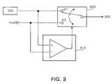
- FIG. 3is a circuit diagram of the current limiter shown in FIG. 2 ;
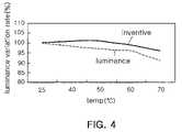
- FIG. 4is a graph illustrating luminance variation-temperature characteristics of the inventive and conventional LED driving apparatuses.
- FIG. 2is a block diagram of an LED driving apparatus of the invention.
- the LED driving apparatus of the inventionincludes a reference voltage generator 100 for generating a first reference voltage Vref 1 , a non-inversion amplification unit 200 for performing non-inversion amplification to a difference voltage between the first reference voltage Vref 1 and a forward voltage Vf with a preset gain Av, a driving unit 300 for adjusting a supply voltage in response to the voltage from the non-inversion amplification unit 200 to supply the adjusted supply voltage to an LED light source 400 and a forward voltage detector 500 for detecting the forward voltage Vf at an anode of LEDs of the LED light source 400 to supply the forward voltage Vf to the non-inversion amplification unit 200 .
- the LED driving apparatus of the inventionfurther includes an on/off switch SW and a current limiter 600 .
- the on/off switch SWacts to switch the connection between a non-inversion input terminal In+ and a supply voltage (Vcc) terminal to turn on/off the operation of the LED light source 400 .
- the current limiter 600if the output voltage of the non-inversion amplification unit 200 is lower than a preset second reference voltage Vref 2 , supplies the second reference voltage Vref 2 in place of the output voltage to the driving unit 300 , thereby limiting the supply voltage of the driving unit 300 .
- the reference voltage generator 100is configured to adjust the first reference voltage Vref 1 in response to user selection.
- the first reference voltage Vref 1can be adjusted by a variable resistor that can adjust division ratio of the supply voltage Vcc.
- the non-inversion amplification unit 200includes a non-inversion operation amplifier OP 1 having an inversion input terminal In ⁇ connected to the first reference voltage Vref 1 from the reference voltage generator 100 .
- the non-inversion input terminal In+ of non-inversion operation amplifier OP 1is connected to the forward voltage Vf of the forward voltage detector 500 .
- the inversion input terminal In ⁇is connected to the first reference voltage (Vref 1 ) terminal via a first resistor R 11 and to the output of the non-inversion operation amplifier OP 1 via a second resistor R 12 , and the non-inversion input terminal In+ is connected to the forward voltage (Vf) terminal via a third resistor R 13 .
- FIG. 3is a circuit diagram of the current limiter shown in FIG. 2 .
- the current limiter 600includes a comparator 610 for comparing the output voltage of the non-inversion amplification unit 200 with the second reference voltage and a switch 620 for selecting a voltage in response to the comparison result of the comparator.
- the switch 620selects a larger one of the output voltage of the non-inversion amplification unit 200 and the second reference voltage Vref 2 .
- the forward voltage detector 500includes a buffer operation amplifier OP 2 for detecting the forward voltage Vf from an anode of LEDs of the LED light source 400 to supply the forward voltage Vf to the non-inversion amplification unit 200 .
- the driving unit 300includes a transistor Q 30 having a base connected to the output terminal of the non-inversion amplification unit 200 , an emitter connected to the supply voltage (Vcc) terminal via a resistor R 30 and a collector connected to the anode of the LEDs of the LED light source 400 ; a capacitor C 30 connected to the base of the transistor Q 30 and the supply voltage (Vcc) terminal to suppress excessive voltage from the switching of the transistor Q 30 ; and a diode D 30 having a cathode connected to the base of the transistor Q 30 and an anode grounded.
- FIG. 4is a graph illustrating brightness variation-temperature characteristics of the inventive and conventional LED driving apparatuses.
- the temperature-luminance variation rate of an LED driving apparatus of the inventionis improved than that of a conventional LED driving apparatus.
- the reference generator 100generates a first reference voltage Vref 1 to be supplied to the non-inversion amplification unit 200 .
- the first reference voltage Vref 1 of the reference voltage generator 100may be adjusted by the user.
- the non-inversion amplification unit 200 of the inventionperforms non-inversion amplification to the difference voltage between the first reference voltage from the reference voltage generator 100 and a forward voltage Vf with a preset gain Av and supplies the amplified difference voltage to the driving unit 300 to adjust the supply voltage of the driving unit.
- the forward voltage detector 500 of the inventiondetects the forward voltage Vf at the anode of the LEDs of the LED light source 400 and supplies the detected forward voltage Vf to the non-inversion amplification unit 200 .
- the LED light source 400includes a plurality of LEDs, in which the forward voltage detector 500 detects the forward voltage Vf at the respective anodes of the LEDs.
- the non-inversion amplification unit 200will now be described in more detail
- the non-inversion operation amplifier OP 1performs non-inversion amplification to the first reference voltage Vref 1 inputted through the inversion input terminal In ⁇ and the forward voltage Vf inputted from the forward voltage detector 400 through the non-inversion input terminal In+.
- the non-inversion operation amplifier OP 1amplifies the difference voltage between the first reference voltage Vref 1 and the forward voltage Vf with a non-inversion gain Av, which is determined by the first resistor R 11 connected to the inversion input terminal In ⁇ , the second resistor R 12 connected to the output and the third resistor R 13 connected to the non-inversion input terminal In+.
- the first reference voltage Vref 1is variable, and the non-inversion amplification gain and the output voltage Vo processed with the non-inversion amplification are as in Equation 1 below:
- Vo( 1 + R ⁇ ⁇ 12 R ⁇ ⁇ 11 ) ⁇ ( Vf - Vref ) - Av ⁇ ( Vr - Vref ⁇ ⁇ 1 ) , Equation ⁇ ⁇ 1
- Vois the output voltage of the non-inversion amplification unit 200
- Vfis the forward voltage
- Vref 1is the first reference voltage
- the usercan turn on/off the LEDs by using the on/off switch SW, which will be described as follows.
- the output voltage of the non-inversion amplification unit 200is applied to the base of the transistor Q 30 of the driving unit 300 .
- the PNP type transistor Q 30operates in response to the output voltage of the non-inversion amplification unit 200 to adjust the supply voltage of the driving unit 300 and thus the brightness of the LED light source 400 .
- the current limiter 600 shown in FIG. 2outputs the second reference voltage Vref 2 in place of the output voltage Vo to the driving unit 300 to limit the supply current of the driving unit 300 , which will be described in detail with reference to FIG. 3 .
- the comparator 610 of the current limiter 600compares the output voltage of the non-inversion amplification unit 200 with the second reference voltage Vref 2 and sends the comparison result as a switching control signal to the switch 620 . Then, the switch 620 makes a selection according to the comparison result of the comparator 610 . That is, the switch 620 selects a larger one of the output voltage of the non-inversion amplification unit 200 and the second reference voltage Vref 2 .
- the forward voltage detector 500is composed of the buffer operation amplifier OP 2 that is a voltage follower, and detects the forward voltage Vf from an anode of the LEDs of the LED light source 400 and supplies the detected forward voltage to the non-inversion amplification unit 200 .
- the buffer operation amplifier OP 2supplies the forward voltage Vf to the non-inversion amplification unit 200 without specific signal amplification, and is used for signal isolation rather than signal amplification.
- the PNP type transistor Q 30 of the driving unit 300adjusts the supply voltage flowing from the supply voltage (Vcc) terminal to the ground in response to the output voltage Vo of the non-inversion amplification unit 200 applied to the base.
- the value of the resistor R 30 connected to the emitter of the transistor Q 30can be adjusted to drive the LEDs with desired luminance and current values.
- the capacitor C 30 connected to the base of the transistor Q 30 and the supply voltage (Vcc) terminalcan suppress excessive voltage by switching operation of the transistor Q 30 .
- the diode D 30having a cathode connected to the base of the transistor Q 30 and a grounded anode, in response to a negative ( ⁇ ) voltage unexpectedly occurring at the output of the non-inversion amplification unit 200 , prevents abrupt drop in the voltage applied to the base of the transistor Q 30 , which otherwise causes excessive current. That is, the diode D 30 allows clipping as much as the forward voltage (e.g., about 0.7V) thereof.
- the LED driving apparatus of the inventioncan realize desired operation characteristics by setting the reference voltage and adjusting the value of the emitter resistor R 30 of the transistor. Furthermore, according to the LED driving apparatus of the invention, it is possible to compensate temperature changes without any specific optical sensor thereby constantly controlling the luminance of the LEDs.
- the LED brightness or luminanceis reduced and the supply voltage is lowered in response to the temperature rise.
- the forward voltage Vfis reduced and the output voltage of the non-inversion amplification unit is also reduced according to Equation 1 above. Since the output voltage of the non-inversion amplification unit is applied to the base of the transistor of the driving unit, the emitter voltage of the transistor is also reduced in response to the reduced base voltage. This as a result increases the emitter voltage. Like this, the emitter current is substantially equal with the collector current and thus the LEDs are driven with the increased current.
- luminance variationcan be compensated according to temperature changes by means of a forward voltage of an LED light source so that the forward voltage of the LED light source is controlled in association with a target current value of ambient temperature.
- Thiscan be realized without the use of an optical sensor or temperature sensor or memory or judging means such as CPU, thereby decreasing an installation space, saving manufacturing costs and promoting design flexibility.
Landscapes
- Engineering & Computer Science (AREA)
- Physics & Mathematics (AREA)
- Computer Hardware Design (AREA)
- General Physics & Mathematics (AREA)
- Theoretical Computer Science (AREA)
- Health & Medical Sciences (AREA)
- Life Sciences & Earth Sciences (AREA)
- Hydrology & Water Resources (AREA)
- Public Health (AREA)
- Water Supply & Treatment (AREA)
- Led Devices (AREA)
- Circuit Arrangement For Electric Light Sources In General (AREA)
Abstract
Description
Claims (9)
Applications Claiming Priority (2)
| Application Number | Priority Date | Filing Date | Title |
|---|---|---|---|
| KR1020060007460AKR100714621B1 (en) | 2006-01-24 | 2006-01-24 | LED driving device with temperature compensation function |
| KR10-2006-0007460 | 2006-01-24 |
Publications (2)
| Publication Number | Publication Date |
|---|---|
| US20070171146A1 US20070171146A1 (en) | 2007-07-26 |
| US7683864B2true US7683864B2 (en) | 2010-03-23 |
Family
ID=38269728
Family Applications (1)
| Application Number | Title | Priority Date | Filing Date |
|---|---|---|---|
| US11/657,083Active2028-11-21US7683864B2 (en) | 2006-01-24 | 2007-01-24 | LED driving apparatus with temperature compensation function |
Country Status (5)
| Country | Link |
|---|---|
| US (1) | US7683864B2 (en) |
| JP (2) | JP4773376B2 (en) |
| KR (1) | KR100714621B1 (en) |
| CN (1) | CN101009081A (en) |
| TW (1) | TWI351898B (en) |
Cited By (36)
| Publication number | Priority date | Publication date | Assignee | Title |
|---|---|---|---|---|
| US20090141049A1 (en)* | 2007-12-04 | 2009-06-04 | Samsung Electronics Co., Ltd. | Display apparatus for compensating optical parameter using forward voltage of led and method thereof |
| US20110063214A1 (en)* | 2008-09-05 | 2011-03-17 | Knapp David J | Display and optical pointer systems and related methods |
| US20110069094A1 (en)* | 2008-09-05 | 2011-03-24 | Knapp David J | Illumination devices and related systems and methods |
| US8749172B2 (en) | 2011-07-08 | 2014-06-10 | Ketra, Inc. | Luminance control for illumination devices |
| US8886047B2 (en) | 2008-09-05 | 2014-11-11 | Ketra, Inc. | Optical communication device, method and system |
| US9146028B2 (en) | 2013-12-05 | 2015-09-29 | Ketra, Inc. | Linear LED illumination device with improved rotational hinge |
| US9155155B1 (en) | 2013-08-20 | 2015-10-06 | Ketra, Inc. | Overlapping measurement sequences for interference-resistant compensation in light emitting diode devices |
| TWI510133B (en)* | 2013-07-26 | 2015-11-21 | Univ Nat Chi Nan | Digital pulse wave drive device for stabilizing the optical power of light emitting diodes |
| TWI511608B (en)* | 2013-05-06 | 2015-12-01 | Ili Technology Corp | Light emitting system and its optical power control device |
| US9237612B1 (en) | 2015-01-26 | 2016-01-12 | Ketra, Inc. | Illumination device and method for determining a target lumens that can be safely produced by an illumination device at a present temperature |
| US9237620B1 (en) | 2013-08-20 | 2016-01-12 | Ketra, Inc. | Illumination device and temperature compensation method |
| US9237623B1 (en) | 2015-01-26 | 2016-01-12 | Ketra, Inc. | Illumination device and method for determining a maximum lumens that can be safely produced by the illumination device to achieve a target chromaticity |
| US9247605B1 (en) | 2013-08-20 | 2016-01-26 | Ketra, Inc. | Interference-resistant compensation for illumination devices |
| US9276766B2 (en) | 2008-09-05 | 2016-03-01 | Ketra, Inc. | Display calibration systems and related methods |
| US9332598B1 (en) | 2013-08-20 | 2016-05-03 | Ketra, Inc. | Interference-resistant compensation for illumination devices having multiple emitter modules |
| US9345097B1 (en) | 2013-08-20 | 2016-05-17 | Ketra, Inc. | Interference-resistant compensation for illumination devices using multiple series of measurement intervals |
| US9360174B2 (en) | 2013-12-05 | 2016-06-07 | Ketra, Inc. | Linear LED illumination device with improved color mixing |
| US9386668B2 (en) | 2010-09-30 | 2016-07-05 | Ketra, Inc. | Lighting control system |
| US9392660B2 (en) | 2014-08-28 | 2016-07-12 | Ketra, Inc. | LED illumination device and calibration method for accurately characterizing the emission LEDs and photodetector(s) included within the LED illumination device |
| US9392663B2 (en) | 2014-06-25 | 2016-07-12 | Ketra, Inc. | Illumination device and method for controlling an illumination device over changes in drive current and temperature |
| US9485813B1 (en) | 2015-01-26 | 2016-11-01 | Ketra, Inc. | Illumination device and method for avoiding an over-power or over-current condition in a power converter |
| US9509525B2 (en) | 2008-09-05 | 2016-11-29 | Ketra, Inc. | Intelligent illumination device |
| US9510416B2 (en) | 2014-08-28 | 2016-11-29 | Ketra, Inc. | LED illumination device and method for accurately controlling the intensity and color point of the illumination device over time |
| US9557214B2 (en) | 2014-06-25 | 2017-01-31 | Ketra, Inc. | Illumination device and method for calibrating an illumination device over changes in temperature, drive current, and time |
| US9578724B1 (en) | 2013-08-20 | 2017-02-21 | Ketra, Inc. | Illumination device and method for avoiding flicker |
| US9651632B1 (en) | 2013-08-20 | 2017-05-16 | Ketra, Inc. | Illumination device and temperature calibration method |
| US9736903B2 (en) | 2014-06-25 | 2017-08-15 | Ketra, Inc. | Illumination device and method for calibrating and controlling an illumination device comprising a phosphor converted LED |
| US9736895B1 (en) | 2013-10-03 | 2017-08-15 | Ketra, Inc. | Color mixing optics for LED illumination device |
| US9769899B2 (en) | 2014-06-25 | 2017-09-19 | Ketra, Inc. | Illumination device and age compensation method |
| US10161786B2 (en) | 2014-06-25 | 2018-12-25 | Lutron Ketra, Llc | Emitter module for an LED illumination device |
| US10210750B2 (en) | 2011-09-13 | 2019-02-19 | Lutron Electronics Co., Inc. | System and method of extending the communication range in a visible light communication system |
| USRE48956E1 (en) | 2013-08-20 | 2022-03-01 | Lutron Technology Company Llc | Interference-resistant compensation for illumination devices using multiple series of measurement intervals |
| USRE48955E1 (en) | 2013-08-20 | 2022-03-01 | Lutron Technology Company Llc | Interference-resistant compensation for illumination devices having multiple emitter modules |
| US11272599B1 (en) | 2018-06-22 | 2022-03-08 | Lutron Technology Company Llc | Calibration procedure for a light-emitting diode light source |
| USRE49454E1 (en) | 2010-09-30 | 2023-03-07 | Lutron Technology Company Llc | Lighting control system |
| USRE50468E1 (en) | 2008-09-05 | 2025-06-24 | Lutron Technology Company Llc | Intelligent illumination device |
Families Citing this family (30)
| Publication number | Priority date | Publication date | Assignee | Title |
|---|---|---|---|---|
| CN100477869C (en)* | 2006-01-26 | 2009-04-08 | 崇贸科技股份有限公司 | Light emitting diode driving circuit with temperature compensation |
| JP2007242886A (en)* | 2006-03-08 | 2007-09-20 | Sony Corp | Light emitting element driving circuit and portable device including the same |
| EP2066149A3 (en)* | 2007-11-27 | 2009-08-19 | Stefan Ruppel | Flat LED lights with heat-dispersing board, in particular for furniture |
| US20100007588A1 (en)* | 2008-07-09 | 2010-01-14 | Adaptive Micro Systems Llc | System and method for led degradation and temperature compensation |
| JPWO2010016440A1 (en)* | 2008-08-08 | 2012-01-19 | シャープ株式会社 | Backlight and display device using the same |
| TWI400990B (en)* | 2008-12-08 | 2013-07-01 | Green Solution Tech Co Ltd | Led driving circuit and controller with temperature compensation |
| CN101772235B (en)* | 2009-01-07 | 2013-02-27 | 登丰微电子股份有限公司 | Light-emitting diode drive circuit with temperature compensation and its controller |
| TWI419606B (en)* | 2010-05-19 | 2013-12-11 | Lite On Electronics Guangzhou | A control circuit of a light emitting diode and apparatus thereof |
| US8947014B2 (en)* | 2010-08-12 | 2015-02-03 | Huizhou Light Engine Ltd. | LED switch circuitry for varying input voltage source |
| US10057952B2 (en)* | 2010-12-15 | 2018-08-21 | Cree, Inc. | Lighting apparatus using a non-linear current sensor and methods of operation thereof |
| TWI440390B (en) | 2011-03-04 | 2014-06-01 | E Ink Holdings Inc | Compensation method and apparatus for light emission diode circuit |
| TWI465149B (en)* | 2011-10-07 | 2014-12-11 | Univ Nat Chi Nan | Automatic color temperature control system, device, circuit and detection module |
| CN103167683B (en)* | 2011-12-19 | 2016-05-11 | 国立暨南国际大学 | Automatic power control system, device, compensation voltage calculation module and detection module |
| CN103384423B (en)* | 2012-05-03 | 2016-12-28 | 海洋王照明科技股份有限公司 | A kind of temperature-compensation circuit and LED |
| TWI514919B (en)* | 2013-01-17 | 2015-12-21 | Univ Nat Chi Nan | Optical power control system and optical power control device and pulse generation module group |
| JP6396431B2 (en) | 2013-05-03 | 2018-09-26 | フィリップス ライティング ホールディング ビー ヴィ | LED lighting circuit |
| JP6205869B2 (en)* | 2013-06-05 | 2017-10-04 | 岩崎電気株式会社 | LED lighting device and LED lighting apparatus |
| US9101020B2 (en)* | 2013-07-15 | 2015-08-04 | Luxmill Electronic Co., Ltd. | LED driver capable of regulating power dissipation and LED lighting apparatus using same |
| CN103490819B (en)* | 2013-09-25 | 2015-09-02 | 武汉恒泰通技术有限公司 | For circuit and the method for optical module current subsection compensation |
| CN103582258B (en)* | 2013-11-03 | 2015-11-04 | 胡军 | LED drive device and method |
| US9900953B2 (en) | 2016-05-31 | 2018-02-20 | Tt Electronics Plc | Temperature compensation in optical sensing system |
| CN106409231B (en)* | 2016-10-31 | 2018-10-12 | 昆山国显光电有限公司 | A kind of luminance compensation method, device and display equipment |
| KR102573744B1 (en) | 2016-11-23 | 2023-09-01 | 삼성디스플레이 주식회사 | Display device and method of driving the same |
| US10295377B2 (en) | 2017-03-29 | 2019-05-21 | Tt Electronics Plc | Systems and methods providing synchronization for multiple optical detectors wherein a radiant power delivered to a second light detector from a first light source is at least 25 percent of radiant power delivered to a first light detector from the first light source |
| CN114253048B (en) | 2017-07-21 | 2024-08-27 | 亮锐控股有限公司 | Method for controlling a segmented flash system |
| CN108648693A (en)* | 2018-07-26 | 2018-10-12 | 武汉精测电子集团股份有限公司 | A kind of drive module for OLED high drives |
| KR102598383B1 (en)* | 2018-12-10 | 2023-11-06 | 엘지디스플레이 주식회사 | Display device and signal inversion device |
| CN110299113B (en)* | 2019-05-09 | 2020-12-11 | 京东方科技集团股份有限公司 | A backlight driving system, backlight driving method and display device |
| US11599133B2 (en)* | 2021-07-13 | 2023-03-07 | Globalfoundries U.S. Inc. | Power supply with integrated voltage regulator and current limiter and method |
| KR102829362B1 (en) | 2023-04-25 | 2025-07-03 | 청주대학교 산학협력단 | Apparatus and method for compensating Illuminance of LED light source |
Citations (5)
| Publication number | Priority date | Publication date | Assignee | Title |
|---|---|---|---|---|
| JPH0395977A (en) | 1989-09-07 | 1991-04-22 | Omron Corp | LED lighting equipment |
| US6831626B2 (en) | 2000-05-25 | 2004-12-14 | Sharp Kabushiki Kaisha | Temperature detecting circuit and liquid crystal driving device using same |
| US7002547B2 (en)* | 2002-01-23 | 2006-02-21 | Seiko Epson Corporation | Backlight control device for liquid crystal display |
| US7286123B2 (en)* | 2005-12-13 | 2007-10-23 | System General Corp. | LED driver circuit having temperature compensation |
| US7298347B2 (en)* | 2000-06-13 | 2007-11-20 | Semiconductor Energy Laboratory Co., Ltd. | Display device |
Family Cites Families (6)
| Publication number | Priority date | Publication date | Assignee | Title |
|---|---|---|---|---|
| JPS63307784A (en)* | 1987-06-09 | 1988-12-15 | Fujitsu Ltd | LED drive circuit |
| KR20030012202A (en)* | 2001-07-31 | 2003-02-12 | (주)엠아이티엔터프라이스 | A Standard Voltage Circuit For Temperature Compensation |
| JP3745310B2 (en)* | 2002-05-31 | 2006-02-15 | ソニー株式会社 | LIGHT EMITTING DEVICE DRIVE DEVICE AND PORTABLE DEVICE USING THE SAME |
| JP3986391B2 (en)* | 2002-08-08 | 2007-10-03 | 株式会社リコー | Constant voltage power circuit |
| JP4704099B2 (en)* | 2004-05-21 | 2011-06-15 | ローム株式会社 | Power supply device and electronic device using the same |
| KR100765361B1 (en)* | 2004-09-14 | 2007-10-09 | 한국정보통신대학교 산학협력단 | Laser diode driving circuit and driving method with automatic temperature compensation |
- 2006
- 2006-01-24KRKR1020060007460Apatent/KR100714621B1/enactiveActive
- 2007
- 2007-01-23JPJP2007012930Apatent/JP4773376B2/enactiveActive
- 2007-01-23TWTW096102438Apatent/TWI351898B/enactive
- 2007-01-24USUS11/657,083patent/US7683864B2/enactiveActive
- 2007-01-24CNCNA2007100026571Apatent/CN101009081A/enactivePending
- 2011
- 2011-05-02JPJP2011103119Apatent/JP5476626B2/enactiveActive
Patent Citations (5)
| Publication number | Priority date | Publication date | Assignee | Title |
|---|---|---|---|---|
| JPH0395977A (en) | 1989-09-07 | 1991-04-22 | Omron Corp | LED lighting equipment |
| US6831626B2 (en) | 2000-05-25 | 2004-12-14 | Sharp Kabushiki Kaisha | Temperature detecting circuit and liquid crystal driving device using same |
| US7298347B2 (en)* | 2000-06-13 | 2007-11-20 | Semiconductor Energy Laboratory Co., Ltd. | Display device |
| US7002547B2 (en)* | 2002-01-23 | 2006-02-21 | Seiko Epson Corporation | Backlight control device for liquid crystal display |
| US7286123B2 (en)* | 2005-12-13 | 2007-10-23 | System General Corp. | LED driver circuit having temperature compensation |
Non-Patent Citations (1)
| Title |
|---|
| Chinese Office Action, with English Translation, issued in Chinese Patent Application No. CN 200710002657.1, dated Sep. 19, 2008. |
Cited By (64)
| Publication number | Priority date | Publication date | Assignee | Title |
|---|---|---|---|---|
| US20090141049A1 (en)* | 2007-12-04 | 2009-06-04 | Samsung Electronics Co., Ltd. | Display apparatus for compensating optical parameter using forward voltage of led and method thereof |
| US9276766B2 (en) | 2008-09-05 | 2016-03-01 | Ketra, Inc. | Display calibration systems and related methods |
| US20110069094A1 (en)* | 2008-09-05 | 2011-03-24 | Knapp David J | Illumination devices and related systems and methods |
| US8773336B2 (en) | 2008-09-05 | 2014-07-08 | Ketra, Inc. | Illumination devices and related systems and methods |
| US8886047B2 (en) | 2008-09-05 | 2014-11-11 | Ketra, Inc. | Optical communication device, method and system |
| USRE50468E1 (en) | 2008-09-05 | 2025-06-24 | Lutron Technology Company Llc | Intelligent illumination device |
| US9509525B2 (en) | 2008-09-05 | 2016-11-29 | Ketra, Inc. | Intelligent illumination device |
| US9295112B2 (en) | 2008-09-05 | 2016-03-22 | Ketra, Inc. | Illumination devices and related systems and methods |
| US10847026B2 (en) | 2008-09-05 | 2020-11-24 | Lutron Ketra, Llc | Visible light communication system and method |
| US20110063214A1 (en)* | 2008-09-05 | 2011-03-17 | Knapp David J | Display and optical pointer systems and related methods |
| USRE49454E1 (en) | 2010-09-30 | 2023-03-07 | Lutron Technology Company Llc | Lighting control system |
| US9386668B2 (en) | 2010-09-30 | 2016-07-05 | Ketra, Inc. | Lighting control system |
| US8749172B2 (en) | 2011-07-08 | 2014-06-10 | Ketra, Inc. | Luminance control for illumination devices |
| US11210934B2 (en) | 2011-09-13 | 2021-12-28 | Lutron Technology Company Llc | Visible light communication system and method |
| US10210750B2 (en) | 2011-09-13 | 2019-02-19 | Lutron Electronics Co., Inc. | System and method of extending the communication range in a visible light communication system |
| US11915581B2 (en) | 2011-09-13 | 2024-02-27 | Lutron Technology Company, LLC | Visible light communication system and method |
| TWI511608B (en)* | 2013-05-06 | 2015-12-01 | Ili Technology Corp | Light emitting system and its optical power control device |
| TWI510133B (en)* | 2013-07-26 | 2015-11-21 | Univ Nat Chi Nan | Digital pulse wave drive device for stabilizing the optical power of light emitting diodes |
| USRE49421E1 (en) | 2013-08-20 | 2023-02-14 | Lutron Technology Company Llc | Illumination device and method for avoiding flicker |
| US9155155B1 (en) | 2013-08-20 | 2015-10-06 | Ketra, Inc. | Overlapping measurement sequences for interference-resistant compensation in light emitting diode devices |
| USRE50018E1 (en) | 2013-08-20 | 2024-06-18 | Lutron Technology Company Llc | Interference-resistant compensation for illumination devices having multiple emitter modules |
| USRE49705E1 (en) | 2013-08-20 | 2023-10-17 | Lutron Technology Company Llc | Interference-resistant compensation for illumination devices using multiple series of measurement intervals |
| US9237620B1 (en) | 2013-08-20 | 2016-01-12 | Ketra, Inc. | Illumination device and temperature compensation method |
| US9345097B1 (en) | 2013-08-20 | 2016-05-17 | Ketra, Inc. | Interference-resistant compensation for illumination devices using multiple series of measurement intervals |
| USRE48955E1 (en) | 2013-08-20 | 2022-03-01 | Lutron Technology Company Llc | Interference-resistant compensation for illumination devices having multiple emitter modules |
| USRE48956E1 (en) | 2013-08-20 | 2022-03-01 | Lutron Technology Company Llc | Interference-resistant compensation for illumination devices using multiple series of measurement intervals |
| US9578724B1 (en) | 2013-08-20 | 2017-02-21 | Ketra, Inc. | Illumination device and method for avoiding flicker |
| US9651632B1 (en) | 2013-08-20 | 2017-05-16 | Ketra, Inc. | Illumination device and temperature calibration method |
| US9247605B1 (en) | 2013-08-20 | 2016-01-26 | Ketra, Inc. | Interference-resistant compensation for illumination devices |
| US9332598B1 (en) | 2013-08-20 | 2016-05-03 | Ketra, Inc. | Interference-resistant compensation for illumination devices having multiple emitter modules |
| US11326761B2 (en) | 2013-10-03 | 2022-05-10 | Lutron Technology Company Llc | Color mixing optics for LED illumination device |
| US12292184B2 (en) | 2013-10-03 | 2025-05-06 | Lutron Technology Company Llc | Color mixing optics for LED illumination device |
| US12072091B2 (en) | 2013-10-03 | 2024-08-27 | Lutron Technology Company Llc | Color mixing optics for LED illumination device |
| US9736895B1 (en) | 2013-10-03 | 2017-08-15 | Ketra, Inc. | Color mixing optics for LED illumination device |
| US11662077B2 (en) | 2013-10-03 | 2023-05-30 | Lutron Technology Company Llc | Color mixing optics for LED illumination device |
| USRE50562E1 (en) | 2013-12-05 | 2025-08-26 | Lutron Technology Company Llc | Linear LED illumination device with improved color mixing |
| US9146028B2 (en) | 2013-12-05 | 2015-09-29 | Ketra, Inc. | Linear LED illumination device with improved rotational hinge |
| USRE50470E1 (en) | 2013-12-05 | 2025-06-24 | Lutron Technology Company Llc | Linear LED illumination device with improved color mixing |
| US9668314B2 (en) | 2013-12-05 | 2017-05-30 | Ketra, Inc. | Linear LED illumination device with improved color mixing |
| USRE48922E1 (en) | 2013-12-05 | 2022-02-01 | Lutron Technology Company Llc | Linear LED illumination device with improved color mixing |
| US9360174B2 (en) | 2013-12-05 | 2016-06-07 | Ketra, Inc. | Linear LED illumination device with improved color mixing |
| US12050126B2 (en) | 2014-06-25 | 2024-07-30 | Lutron Technology Company Llc | Emitter module for an LED illumination device |
| US10595372B2 (en) | 2014-06-25 | 2020-03-17 | Lutron Ketra, Llc | Illumination device and method for calibrating an illumination device over changes in temperature, drive current, and time |
| US9769899B2 (en) | 2014-06-25 | 2017-09-19 | Ketra, Inc. | Illumination device and age compensation method |
| US9557214B2 (en) | 2014-06-25 | 2017-01-31 | Ketra, Inc. | Illumination device and method for calibrating an illumination device over changes in temperature, drive current, and time |
| US10161786B2 (en) | 2014-06-25 | 2018-12-25 | Lutron Ketra, Llc | Emitter module for an LED illumination device |
| US9736903B2 (en) | 2014-06-25 | 2017-08-15 | Ketra, Inc. | Illumination device and method for calibrating and controlling an illumination device comprising a phosphor converted LED |
| US12292326B2 (en) | 2014-06-25 | 2025-05-06 | Lutron Technology Company Llc | Emitter module for an LED illumination device |
| US10605652B2 (en) | 2014-06-25 | 2020-03-31 | Lutron Ketra, Llc | Emitter module for an LED illumination device |
| US12052807B2 (en) | 2014-06-25 | 2024-07-30 | Lutron Technology Company Llc | Illumination device and method for calibrating an illumination device over changes in temperature, drive current, and time |
| US11252805B2 (en) | 2014-06-25 | 2022-02-15 | Lutron Technology Company Llc | Illumination device and method for calibrating an illumination device over changes in temperature, drive current, and time |
| US9392663B2 (en) | 2014-06-25 | 2016-07-12 | Ketra, Inc. | Illumination device and method for controlling an illumination device over changes in drive current and temperature |
| US11243112B2 (en) | 2014-06-25 | 2022-02-08 | Lutron Technology Company Llc | Emitter module for an LED illumination device |
| US9392660B2 (en) | 2014-08-28 | 2016-07-12 | Ketra, Inc. | LED illumination device and calibration method for accurately characterizing the emission LEDs and photodetector(s) included within the LED illumination device |
| USRE49479E1 (en) | 2014-08-28 | 2023-03-28 | Lutron Technology Company Llc | LED illumination device and calibration method for accurately characterizing the emission LEDs and photodetector(s) included within the LED illumination device |
| US9510416B2 (en) | 2014-08-28 | 2016-11-29 | Ketra, Inc. | LED illumination device and method for accurately controlling the intensity and color point of the illumination device over time |
| USRE49246E1 (en) | 2014-08-28 | 2022-10-11 | Lutron Technology Company Llc | LED illumination device and method for accurately controlling the intensity and color point of the illumination device over time |
| US9237623B1 (en) | 2015-01-26 | 2016-01-12 | Ketra, Inc. | Illumination device and method for determining a maximum lumens that can be safely produced by the illumination device to achieve a target chromaticity |
| US9237612B1 (en) | 2015-01-26 | 2016-01-12 | Ketra, Inc. | Illumination device and method for determining a target lumens that can be safely produced by an illumination device at a present temperature |
| US9485813B1 (en) | 2015-01-26 | 2016-11-01 | Ketra, Inc. | Illumination device and method for avoiding an over-power or over-current condition in a power converter |
| USRE49137E1 (en) | 2015-01-26 | 2022-07-12 | Lutron Technology Company Llc | Illumination device and method for avoiding an over-power or over-current condition in a power converter |
| USRE50612E1 (en) | 2015-01-26 | 2025-09-30 | Lutron Technology Company Llc | Illumination device and method for avoiding an over-power or over-current condition in a power converter |
| US12302466B1 (en) | 2018-06-22 | 2025-05-13 | Lutron Technology Company Llc | Calibration procedure for a light-emitting diode light source |
| US11272599B1 (en) | 2018-06-22 | 2022-03-08 | Lutron Technology Company Llc | Calibration procedure for a light-emitting diode light source |
Also Published As
| Publication number | Publication date |
|---|---|
| CN101009081A (en) | 2007-08-01 |
| JP2007201470A (en) | 2007-08-09 |
| TWI351898B (en) | 2011-11-01 |
| JP4773376B2 (en) | 2011-09-14 |
| TW200738061A (en) | 2007-10-01 |
| KR100714621B1 (en) | 2007-05-07 |
| US20070171146A1 (en) | 2007-07-26 |
| JP2011181515A (en) | 2011-09-15 |
| JP5476626B2 (en) | 2014-04-23 |
Similar Documents
| Publication | Publication Date | Title |
|---|---|---|
| US7683864B2 (en) | LED driving apparatus with temperature compensation function | |
| US7944189B2 (en) | Load driving device and portable apparatus utilizing such driving device | |
| US7812553B2 (en) | LED lighting device and method for controlling the same based on temperature changes | |
| US8121160B2 (en) | Driver circuit for semiconductor laser diode driven in differential mode | |
| US7940014B2 (en) | Apparatus for driving light emitting element | |
| US8659235B2 (en) | Process and circuitry for controlling a load | |
| US7916101B2 (en) | LED driving apparatus and method of controlling luminous power | |
| JP5591848B2 (en) | Adaptive switch mode LED system | |
| US20060261754A1 (en) | LED driving circuit having dimming circuit | |
| US9491824B2 (en) | Method and apparatus for precise temperature brightness compensation of LED | |
| US20060007107A1 (en) | Dual-slope brightness control for transflective displays | |
| JP2007042758A (en) | LED drive device | |
| US20070194210A1 (en) | Light emitting apparatus and control method thereof | |
| KR20130050828A (en) | Backlight unit and display device including the same | |
| JP2010015728A (en) | Backlight dimming control device | |
| KR20070015857A (en) | LED driving device | |
| US7081720B2 (en) | Driver circuit and method for driving electroluminescent lamp to emit light at brightness set level | |
| US20080128594A1 (en) | Backlight module with controlled output light intensity and driving method for same | |
| CN114974116A (en) | Pixel driving circuit and pixel driving method | |
| US7812834B2 (en) | DC stabilization circuit for organic electroluminescent display device and power supply using the same | |
| JP2005110356A (en) | Load driver and portable apparatus | |
| US7834602B2 (en) | Feedback power control system for an electrical component | |
| US9494961B2 (en) | Feedback device and method for constant current driver | |
| JP5511758B2 (en) | Lighting device and display device | |
| KR20110034796A (en) | Feedback unit of backlight unit |
Legal Events
| Date | Code | Title | Description |
|---|---|---|---|
| AS | Assignment | Owner name:SAMSUNG ELECTRO-MECHANICS CO., LTD., KOREA, REPUBL Free format text:ASSIGNMENT OF ASSIGNORS INTEREST;ASSIGNORS:LEE, DONG WOO;HWANG, SOO RYONG;PARK, MOO YOUN;REEL/FRAME:018827/0031 Effective date:20070118 Owner name:SAMSUNG ELECTRO-MECHANICS CO., LTD.,KOREA, REPUBLI Free format text:ASSIGNMENT OF ASSIGNORS INTEREST;ASSIGNORS:LEE, DONG WOO;HWANG, SOO RYONG;PARK, MOO YOUN;REEL/FRAME:018827/0031 Effective date:20070118 | |
| FEPP | Fee payment procedure | Free format text:PAYOR NUMBER ASSIGNED (ORIGINAL EVENT CODE: ASPN); ENTITY STATUS OF PATENT OWNER: LARGE ENTITY | |
| STCF | Information on status: patent grant | Free format text:PATENTED CASE | |
| AS | Assignment | Owner name:SAMSUNG ELECTRO-MECHANICS CO., LTD., KOREA, REPUBL Free format text:ASSIGNMENT OF ASSIGNORS INTEREST;ASSIGNOR:SAMSUNG ELECTRO-MECHANICS CO., LTD.;REEL/FRAME:024728/0467 Effective date:20100419 Owner name:SAMSUNG LED CO., LTD., KOREA, REPUBLIC OF Free format text:ASSIGNMENT OF ASSIGNORS INTEREST;ASSIGNOR:SAMSUNG ELECTRO-MECHANICS CO., LTD.;REEL/FRAME:024728/0467 Effective date:20100419 | |
| AS | Assignment | Owner name:SAMSUNG ELECTRONICS CO., LTD., KOREA, REPUBLIC OF Free format text:MERGER;ASSIGNOR:SAMSUNG LED CO., LTD.;REEL/FRAME:028744/0272 Effective date:20120403 | |
| FPAY | Fee payment | Year of fee payment:4 | |
| AS | Assignment | Owner name:SAMSUNG ELECTRONICS CO., LTD., KOREA, REPUBLIC OF Free format text:ASSIGNMENT OF ASSIGNORS INTEREST;ASSIGNOR:SAMSUNG ELECTRO-MECHANICS CO., LTD.;REEL/FRAME:031933/0143 Effective date:20131230 | |
| MAFP | Maintenance fee payment | Free format text:PAYMENT OF MAINTENANCE FEE, 8TH YEAR, LARGE ENTITY (ORIGINAL EVENT CODE: M1552) Year of fee payment:8 | |
| MAFP | Maintenance fee payment | Free format text:PAYMENT OF MAINTENANCE FEE, 12TH YEAR, LARGE ENTITY (ORIGINAL EVENT CODE: M1553); ENTITY STATUS OF PATENT OWNER: LARGE ENTITY Year of fee payment:12 |