US7682072B2 - Method of measuring thermal conductivity of honeycomb structure - Google Patents
Method of measuring thermal conductivity of honeycomb structureDownload PDFInfo
- Publication number
- US7682072B2 US7682072B2US10/505,334US50533404AUS7682072B2US 7682072 B2US7682072 B2US 7682072B2US 50533404 AUS50533404 AUS 50533404AUS 7682072 B2US7682072 B2US 7682072B2
- Authority
- US
- United States
- Prior art keywords
- honeycomb structure
- thermal conductivity
- measurement
- thermal
- conductivity
- Prior art date
- Legal status (The legal status is an assumption and is not a legal conclusion. Google has not performed a legal analysis and makes no representation as to the accuracy of the status listed.)
- Expired - Lifetime, expires
Links
- 238000000034methodMethods0.000titleclaimsabstractdescription49
- 238000005259measurementMethods0.000claimsabstractdescription47
- 239000011810insulating materialSubstances0.000claimsdescription12
- 239000000463materialSubstances0.000claimsdescription11
- HBMJWWWQQXIZIP-UHFFFAOYSA-Nsilicon carbideChemical compound[Si+]#[C-]HBMJWWWQQXIZIP-UHFFFAOYSA-N0.000claimsdescription8
- 229910010271silicon carbideInorganic materials0.000claimsdescription8
- 229910052710siliconInorganic materials0.000claimsdescription4
- 239000010703siliconSubstances0.000claimsdescription4
- 229910052581Si3N4Inorganic materials0.000claimsdescription3
- 239000002131composite materialSubstances0.000claimsdescription3
- 238000005192partitionMethods0.000claimsdescription3
- HQVNEWCFYHHQES-UHFFFAOYSA-Nsilicon nitrideChemical compoundN12[Si]34N5[Si]62N3[Si]51N64HQVNEWCFYHHQES-UHFFFAOYSA-N0.000claimsdescription3
- 239000000126substanceSubstances0.000claimsdescription3
- 238000012360testing methodMethods0.000abstractdescription14
- OKTJSMMVPCPJKN-UHFFFAOYSA-NCarbonChemical compound[C]OKTJSMMVPCPJKN-UHFFFAOYSA-N0.000description5
- 229910052799carbonInorganic materials0.000description5
- 238000002360preparation methodMethods0.000description5
- 239000011888foilSubstances0.000description3
- 239000007789gasSubstances0.000description3
- 229920006327polystyrene foamPolymers0.000description3
- 239000002912waste gasSubstances0.000description3
- CSCPPACGZOOCGX-UHFFFAOYSA-NAcetoneChemical compoundCC(C)=OCSCPPACGZOOCGX-UHFFFAOYSA-N0.000description2
- 239000004793PolystyreneSubstances0.000description2
- 229910052782aluminiumInorganic materials0.000description2
- XAGFODPZIPBFFR-UHFFFAOYSA-NaluminiumChemical compound[Al]XAGFODPZIPBFFR-UHFFFAOYSA-N0.000description2
- 210000004027cellAnatomy0.000description2
- 239000000919ceramicSubstances0.000description2
- 239000000428dustSubstances0.000description2
- 230000017525heat dissipationEffects0.000description2
- 239000013618particulate matterSubstances0.000description2
- 229920002223polystyrenePolymers0.000description2
- 239000000843powderSubstances0.000description2
- RYGMFSIKBFXOCR-UHFFFAOYSA-NCopperChemical compound[Cu]RYGMFSIKBFXOCR-UHFFFAOYSA-N0.000description1
- RQMIWLMVTCKXAQ-UHFFFAOYSA-N[AlH3].[C]Chemical compound[AlH3].[C]RQMIWLMVTCKXAQ-UHFFFAOYSA-N0.000description1
- 230000004888barrier functionEffects0.000description1
- 238000010276constructionMethods0.000description1
- 229910052802copperInorganic materials0.000description1
- 239000010949copperSubstances0.000description1
- 238000005260corrosionMethods0.000description1
- 230000007797corrosionEffects0.000description1
- 238000013461designMethods0.000description1
- 238000001125extrusionMethods0.000description1
- 238000001914filtrationMethods0.000description1
- 239000012530fluidSubstances0.000description1
- 239000006260foamSubstances0.000description1
- 210000000497foam cellAnatomy0.000description1
- 238000004898kneadingMethods0.000description1
- 238000004519manufacturing processMethods0.000description1
- 229910052751metalInorganic materials0.000description1
- 239000002184metalSubstances0.000description1
- 239000003960organic solventSubstances0.000description1
- 229920002635polyurethanePolymers0.000description1
- 239000004814polyurethaneSubstances0.000description1
- 238000012545processingMethods0.000description1
- 238000000746purificationMethods0.000description1
- 239000002994raw materialSubstances0.000description1
- 229910052709silverInorganic materials0.000description1
- 239000004332silverSubstances0.000description1
- 239000002699waste materialSubstances0.000description1
Images

Classifications
- G—PHYSICS
- G01—MEASURING; TESTING
- G01N—INVESTIGATING OR ANALYSING MATERIALS BY DETERMINING THEIR CHEMICAL OR PHYSICAL PROPERTIES
- G01N25/00—Investigating or analyzing materials by the use of thermal means
- G01N25/18—Investigating or analyzing materials by the use of thermal means by investigating thermal conductivity
Definitions
- the present inventionrelates to a method for measurement of thermal conductivity of a honeycomb structure, which can measure the thermal conductivity of a honeycomb structure in the shape of the honeycomb structure per se without preparing a test specimen or the like.
- Honeycomb structuresmade of a ceramic are in use in order to capture the dust or another particulate matter contained in, for example, the exhaust gas emitted from automobiles (particularly, diesel engine automobiles) or the incineration gas generating during the incineration of waste, or to recover a product or a raw material from the high-temperature waste gas emitted in production processes of various industries.
- honeycomb structureshave a large number of through-holes surrounded by partition walls and extending in the axial direction of a honeycomb structure; the partition walls surrounding the through-holes have a filtration ability; a given number of the through-holes are plugged at one end of a honeycomb structure and the remaining through-holes are plugged at the other end of a honeycomb structure; thus, the honeycomb structures are formed so as to enable the capture and removal of the particulate matter contained in a dust-containing fluid.
- the ceramic-made honeycomb structuresare superior in heat resistance and corrosion resistance and have suitable properties as a filter material used in a high temperature, corrosive gas atmosphere and, therefore, are in use for purification of various exhaust or waste gases.
- honeycomb structureA high-temperature exhaust or waste gas is often passed through such a honeycomb structure and, in that case, the honeycomb structure generates a thermal strain in various forms depending upon its thermal conductivity.
- the honeycomb structureit is necessary to grasp its thermal conductivity.
- the honeycomb structurehas a special construction, there has heretofore been established no method for measuring the thermal conductivity of the honeycomb structure per se without preparing a test specimen or the like.
- the method for measuring the thermal conductivity of a fine ceramicthere is, for example, a laser flash method which is specified in JIS R 1611.
- This methodhas restrictions; for example, the method is restricted to a material having a porosity of 10% or less and also to a test specimen of flat plate having, for example, a square shape of 10 mm ⁇ 10 mm or less. Therefore, this method has been unable to apply to any honeycomb structure because of its material and shape. Further, the method has had an operational problem because a test specimen need be prepared.
- the present inventionhas been made in view of the above-mentioned problems and aims at providing a method for measurement of thermal conductivity of a honeycomb structure which can measure the thermal conductivity of a honeycomb structure in the shape of the honeycomb structure per se or in a predetermined block shape without preparing, for example, a test specimen of particular shape.
- the present inventionprovides the following method for measurement of thermal conductivity of a honeycomb structure.
- thermal conductivity ⁇ (W/mK) of the honeycomb structureis specified in relation to:
- FIG. 1is a side view showing a honeycomb structure and contact members which are in contact with the two ends of the honeycomb structure, in one embodiment of the method for measurement of thermal conductivity of a honeycomb structure according to the present invention.
- FIG. 2is a sectional view of a honeycomb structure, contact members, etc. along a plane including the axis of the honeycomb structure, in another embodiment of the method for measurement of thermal conductivity of a honeycomb structure according to the present invention.
- the thermal conductivity of a honeycomb structureis measured with keeping the whole honeycomb structure in a steady temperature state; thereby, the thermal conductivity can be measured easily with, for example, a cylindrical honeycomb structure per se or a block of predetermined size cut out therefrom, irrespective of the shape of the honeycomb structure to be measured and it is not necessary to prepare a test specimen of particular shape.
- FIG. 1is a side view showing a honeycomb structure and contact members which are in contact with the two ends of the honeycomb structure, in one embodiment of the method for measurement of thermal conductivity of a honeycomb structure according to the present invention.
- the two ends of the honeycomb structure in its axial directionare kept at given different temperatures.
- contact members 2 ( 21 and 22 ) kept at respective given temperaturesare contacted with the two ends 11 and 12 of a honeycomb structure 1 in its axial direction, as shown in FIG. 1 .
- the thermal conductivity A (W/mK) of the honeycomb structure 1is calculated from the following expression (1) wherein the thermal conductivity A (W/mK) of the honeycomb structure is specified in relation to:
- measurement of thermal conductivityis made with the whole honeycomb structure being kept in a steady temperature state; therefore, the measurement of thermal conductivity can be made easily with, for example, a cylindrical honeycomb structure per se or a block of predetermined size cut out therefrom, irrespective of the shape of the honeycomb structure to be measured and it is not necessary to prepare a test specimen of particular shape.
- Such a method for measurement of thermal conductivityis called a steady method (JIS A 1412) but has not been applied to honeycomb structures.
- each end ( 11 , 12 ) of the honeycomb structure 1 and each contact member ( 21 , 22 )is made as good as possible and the thermal conduction between the contact member 21 and the end 11 of the honeycomb structure 1 as well as between the end 12 of the honeycomb structure 1 and the contact member 22 is made as high as possible without heat loss.
- the losses of the amount of heat flow in these areasare regarded as indicating a barrier of the thermal conduction of the honeycomb structure per se and, therefore, may decrease the accuracy of measurement of the thermal conductivity of the honeycomb structure.
- the heat dissipation from the exposed portion of the side of the honeycomb structure 1 when a heat flows through the honeycomb structure 1is as small as possible.
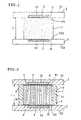
- FIG. 2is a sectional view of a honeycomb structure, contact members, etc. along a plane including the axis of the honeycomb structure, in another embodiment for carrying out the method for measurement of thermal conductivity of a honeycomb structure according to the present invention.
- each end ( 11 , 12 ) of the honeycomb structure 1 and each contact member ( 21 , 22 )was conducted, as shown in FIG. 2 , to contact the contact member 21 with the end 11 of the honeycomb structure via a high-thermal-conductivity member 41 and contact the contact member 22 with the end 12 of the honeycomb structure via a high-thermal-conductivity member 42 .
- each contact member ( 21 , 22 ) with each end ( 11 , 12 ) of the honeycomb structure via each high-thermal-conductivity member ( 41 , 42 )By thus contacting each contact member ( 21 , 22 ) with each end ( 11 , 12 ) of the honeycomb structure via each high-thermal-conductivity member ( 41 , 42 ), the gap formed in the contact between the face of the end 11 of the honeycomb structure and the contact face 211 of the contact member 21 owing to, for example, the fine surface unevennesses of the face and the contact face, becomes less because of the use of the high-thermal-conductivity member 4 . Thereby, thermal conduction is improved and the measurement of thermal conductivity of a honeycomb structure can be made at higher accuracy.
- the high-thermal-conductivity member 4Since the high-thermal-conductivity member 4 has a high thermal conductivity, measurement of thermal conductivity of a honeycomb structure with the member 4 being present between each end ( 11 , 12 ) of a honeycomb structure and each contact member ( 21 , 22 ) gives no large measurement error.
- the high-thermal-conductivity member 4is preferred to be a flexible sheet. This flexible sheet can be deformed into the shape of the above-mentioned gap formed between the two contact faces and can fill the gap, whereby good thermal conduction is obtained.
- As the material for the high-thermal-conductivity member 4 of a flexible sheetthere is preferred a carbon sheet or a metal foil of aluminum, copper or the like.
- the high-thermal conductivity member 4is preferred to be as thin as possible relative to the test specimen used, in order to minimize the influence on measured thermal conductivity value.
- a corrected thermal conductivity ⁇ 1 (W/mK) of the test specimen (honeycomb structure 1 )is calculated according to the following expression (2) using the thermal conductivity ⁇ 2 (W/mK) and thickness L 2 (m) of the material for the high-thermal-conductivity member 4 .
- ⁇ 1L 1/[ L/ ⁇ L 2/ ⁇ 2] (2)
- the high-thermal-conductivity member 4may be a film formed by applying, on the contact faces of the ends 11 and 12 of the honeycomb structure, a paste containing a high-thermal-conductivity substance (powder) such as carbon, silver or the like (the paste is obtained, for example, by kneading the powder with an organic solvent represented by acetone).
- the pastemy be applied on the contact face of the end ( 11 , 12 ) of the honeycomb structure and/or on the contact face ( 211 , 222 ) of each contact member ( 21 , 22 ). By applying the paste, the gap formed between the above contact face can be filled as well and good thermal conduction can be obtained.
- the contact pressure when the contact member 2 is in contact with the honeycomb structure 1 or with the high-thermal conductivity member 4at 1 to 10 kg/cm 2 , the gap formed between the contact face can be filled and good thermal conduction can be obtained.
- measurement of thermal conductivitycan be made preferably when the honeycomb structure to be measured is made of a material having a thermal conductivity of 1 (W/mK) or more. Particularly when measurement of thermal conductivity is made using a high-thermal-conductivity member between a honeycomb structure and contact member, thermal conduction is good and the thermal conductivity of a honeycomb structure of high thermal conductivity can be measured at high accuracy.
- the material for honeycomb structurethere can be mentioned silicon carbide, a composite material of silicon carbide and metallic silicon, silicon nitride and non-oxides having a relatively high thermal conductivity.
- the methodcan preferably applied to oxides when they have a thermal conductivity of 1 W/mK or more.
- the exposed portion 13 of the side of a honeycomb structure 1is covered with a heat-insulating material 5 .
- Covering it with the heat-insulating material 5suppresses heat dissipation from the exposed side portion 13 during measurement of thermal conductivity, whereby measurement of thermal conductivity can be made at high accuracy.
- the heat-insulating materialthere can be mentioned, for example, a polyurethane mat and a polystyrene foam.
- the area to be covered with the heat-insulating materialmay be not only the exposed side portion 13 but also the whole portion including the contact members 2 . It is also preferred to surround the honeycomb structure with the honeycomb structures made of the same material in place of using the heat-insulating material, because it is effective for making homogeneous the heat flow in the honeycomb structure.
- honeycomb structuresmade of metallic silicon-bonded silicon carbide (silicon carbide bonded with metallic silicon) and having a rib thickness of 15 mil and a cell density of 200 cpsi (cells per square inch) or 300 cpsi.
- a block of 35 mm ⁇ 35 mm ⁇ 25 mmwas cut out from each of the two kinds of honeycomb structures and measured for thermal conductivity by a steady method, using neither high-thermal-conductivity member nor heat-insulating material, as shown in FIG. 1 .
- Each blockwas measured for thermal conductivity by the steady method using both or either of high-thermal-conductivity members and a heat-insulating material, as shown in FIG. 2 .
- the resultsare shown in Table 1.
- Example 1Example 2
- Example 3Example 4
- Example 5Example 6
- Example 7High-thermal-conductivity member Not used Carbon sheet Not used Aluminum Carbon sheet Not used Carbon foil sheet Heat-insulating material Not used Not used Polystyrene Not used Polystyrene Not used Polystyrene foam foam foam foam Cell density (cpsi) 200 200 200 200 200 300 300 Opening ratio (%) 62 62 62 62 55 55 Effective area ratio (%) 38 38 38 38 38 38 45 45 Thermal conductivity, 11 11 11 11 14 14 converted value (W/mK) Thermal conductivity, 4 12 8 8 12 6 15 measured value (W/mK)
- thermal conductivity, converted valuemeans a value obtained by measuring the thermal conductivity of a honeycomb structure by the laser flash method based on JIS R 1611, using a test specimen of particular shape and then multiplying the measured thermal conductivity by an effective area ratio which indicates an effective end face area obtained by subtracting the total opening area of the end face of the honeycomb structure from the area of the end face, to convert the measured thermal conductivity into the thermal conductivity of the honeycomb structure per se.
- the thermal conductivity of a honeycomb structure measured by the laser flash methodincludes an error associated with the porosity, etc. but has certain accuracy; therefore, the measured thermal conductivity in the present Examples was evaluated in comparison with the thermal conductivity measured by the laser flash method.
- the thermal conductivity of a honeycomb structurecan be measured by a steady temperature method. As indicated in Examples 1 and 6, the measurement of thermal conductivity is possible even when neither high-thermal-conductivity member nor heat-insulating material is used; however, a value nearer to that of the laser flash method is obtainable by using an aluminum foil or a carbon sheet as high-thermal-conductivity members or a polystyrene foam as a heat-insulating material (Examples 2 to 5 and 7).
- preparation of a flat plate of 10 mm ⁇ 10 mm ⁇ 1 mm or lessis not necessary and measurement of thermal conductivity can be made using a test specimen of block shape; therefore, workability of sample preparation is improved and the time for sample preparation is shortened.
Landscapes
- Physics & Mathematics (AREA)
- Health & Medical Sciences (AREA)
- Life Sciences & Earth Sciences (AREA)
- Chemical & Material Sciences (AREA)
- Analytical Chemistry (AREA)
- Biochemistry (AREA)
- General Health & Medical Sciences (AREA)
- General Physics & Mathematics (AREA)
- Immunology (AREA)
- Pathology (AREA)
- Investigating Or Analyzing Materials Using Thermal Means (AREA)
- Laminated Bodies (AREA)
Abstract
Description
- [1] A method for measurement of thermal conductivity of a honeycomb structure, the method comprising the steps of:
- [2] The method for measurement of thermal conductivity of a honeycomb structure set forth in the above [1], wherein contact members kept at given different temperatures are contacted with the two ends of the honeycomb structure to keep the two ends of the honeycomb structure at given different temperatures.
- [3] The method for measurement of thermal conductivity of a honeycomb structure set forth in the above [2], wherein the thermal conductivity A (W/mK) of the honeycomb structure is calculated from the following expression (1):
λ=QH·[L/(T1−T2)] (1)
- [4] The method for measurement of thermal conductivity of a honeycomb structure set forth in the above [2] or [3], wherein the two ends of the honeycomb structure and the contact members are contacted with each other via high-thermal-conductivity members.
- [5] The method for measurement of thermal conductivity of a honeycomb structure set forth in the above [4], wherein a sheet having flexibility is used as the high-thermal-conductivity member.
- [6] The method for measurement of thermal conductivity of a honeycomb structure set forth in the above [4] or [5], wherein the high-thermal-conductivity member is made of a film formed by applying a paste containing a substance of high thermal conductivity, on a contact face of the honeycomb structure and/or the contact member.
- [7] The method for measurement of thermal conductivity of a honeycomb structure set forth in any of the above [2] to [6], wherein a contact pressure between the contact member and the end of the honeycomb structure is set at 1 to 10 kg/cm2.
- [8] The method for measurement of thermal conductivity of a honeycomb structure set forth in any of the above [1] to [7], wherein an exposed portion of the side of the honeycomb structure is covered with a heat-insulating material.
- [9] The method for measurement of thermal conductivity of a honeycomb structure set forth in any of the above [1] to [8], wherein the honeycomb structure is made of a material having a thermal conductivity of 1 (W/mK) or more.
- [10] The method for measurement of thermal conductivity of a honeycomb structure set forth in any of the above [1] to [9], wherein the honeycomb structure contains at least one kind selected from the group consisting of silicon carbide, a composite of silicon carbide and metallic silicon, and silicon nitride.
λ=QH·[L/(T1−T2)] (1)
λ1=L1/[L/λ−L2/λ2] (2)
- λ: thermal conductivity (W/mK) of honeycomb structure
- λ1: corrected thermal conductivity (W/mK) of honeycomb structure
- λ2: thermal conductivity (W/mK) of high-thermal-conductivity member
- L: total thickness (m) of honeycomb structure and two high-thermal-conductivity members provided at two end of honeycomb structure
- L1: thickness (m) of honeycomb structure
- L2: thickness (m) of high-thermal-conductivity member
| TABLE 1 | ||||||||
| Example 1 | Example 2 | Example 3 | Example 4 | Example 5 | Example 6 | Example 7 | ||
| High-thermal-conductivity member | Not used | Carbon sheet | Not used | Aluminum | Carbon sheet | Not used | Carbon |
| foil | sheet | ||||||
| Heat-insulating material | Not used | Not used | Polystyrene | Not used | Polystyrene | Not used | Polystyrene |
| foam | foam | foam | |||||
| Cell density (cpsi) | 200 | 200 | 200 | 200 | 200 | 300 | 300 |
| Opening ratio (%) | 62 | 62 | 62 | 62 | 62 | 55 | 55 |
| Effective area ratio (%) | 38 | 38 | 38 | 38 | 38 | 45 | 45 |
| Thermal conductivity, | 11 | 11 | 11 | 11 | 11 | 14 | 14 |
| converted value (W/mK) | |||||||
| Thermal conductivity, | 4 | 12 | 8 | 8 | 12 | 6 | 15 |
| measured value (W/mK) | |||||||
Claims (8)
λ=QH·[L/(T1−T2)] (1)
Applications Claiming Priority (3)
| Application Number | Priority Date | Filing Date | Title |
|---|---|---|---|
| JP2002-077557 | 2002-03-20 | ||
| JP2002077557AJP4155749B2 (en) | 2002-03-20 | 2002-03-20 | Method for measuring thermal conductivity of honeycomb structure |
| PCT/JP2003/003083WO2003078988A1 (en) | 2002-03-20 | 2003-03-14 | Method of measuring thermal conductivity of honeycomb structure |
Publications (2)
| Publication Number | Publication Date |
|---|---|
| US20050105584A1 US20050105584A1 (en) | 2005-05-19 |
| US7682072B2true US7682072B2 (en) | 2010-03-23 |
Family
ID=28035527
Family Applications (1)
| Application Number | Title | Priority Date | Filing Date |
|---|---|---|---|
| US10/505,334Expired - LifetimeUS7682072B2 (en) | 2002-03-20 | 2003-03-14 | Method of measuring thermal conductivity of honeycomb structure |
Country Status (7)
| Country | Link |
|---|---|
| US (1) | US7682072B2 (en) |
| EP (1) | EP1486774B1 (en) |
| JP (1) | JP4155749B2 (en) |
| KR (1) | KR20040094813A (en) |
| AU (1) | AU2003213376A1 (en) |
| PL (1) | PL210071B1 (en) |
| WO (1) | WO2003078988A1 (en) |
Families Citing this family (12)
| Publication number | Priority date | Publication date | Assignee | Title |
|---|---|---|---|---|
| JP2002131257A (en)* | 2000-10-26 | 2002-05-09 | Nisshinbo Ind Inc | Thermal conductivity measuring method, measuring apparatus and method of manufacturing heat insulating material |
| US7077563B2 (en)* | 2003-11-19 | 2006-07-18 | General Electric Company | Deposition sensor based on differential heat flux measurement |
| US7226206B2 (en)* | 2005-05-12 | 2007-06-05 | Guardian Building Products, Inc. | Dynamic heat flow meter for measuring thermal properties of insulation or the like, and corresponding method |
| WO2009054473A1 (en)* | 2007-10-26 | 2009-04-30 | Toppan Printing Co., Ltd. | Reaction chip, reaction method, temperature controlling unit for gene treating apparatus and gene treating apparatus |
| US8517600B2 (en)* | 2009-10-27 | 2013-08-27 | General Electric Company | Deposition sensor based on differential heat transfer resistance |
| JP5827097B2 (en)* | 2011-10-17 | 2015-12-02 | ニチアス株式会社 | Thermal conductivity measurement method |
| JP5990095B2 (en)* | 2012-12-18 | 2016-09-07 | 日本碍子株式会社 | Particulate filter |
| US10161810B2 (en)* | 2013-06-10 | 2018-12-25 | Mitsubishi Electric Corporation | Honeycomb sandwich structure and method of manufacturing honeycomb sandwich structure |
| CN103499604A (en)* | 2013-09-30 | 2014-01-08 | 中国航天科工集团第六研究院二一○所 | Device and method for testing heat conductivity coefficient of composite honeycomb plate |
| KR101713443B1 (en)* | 2015-10-19 | 2017-03-07 | 울산대학교 산학협력단 | Apparatus and method for evaluating heating element |
| CN105572163B (en)* | 2016-01-23 | 2018-08-21 | 太原理工大学 | Heat conducting coefficient measurement device under concrete drying regime |
| US11137362B2 (en) | 2019-12-10 | 2021-10-05 | Covestro Llc | Method for assessing the long-term thermal resistance of closed-cell thermal insulating foams at multiple mean temperatures |
Citations (34)
| Publication number | Priority date | Publication date | Assignee | Title |
|---|---|---|---|---|
| US3238775A (en)* | 1962-01-02 | 1966-03-08 | Lockheed Aircraft Corp | Heat flux responsive device |
| US4155244A (en)* | 1977-12-30 | 1979-05-22 | Owens-Corning Fiberglas Corporation | Apparatus for determining thermal conductivity of materials |
| JPS54123082A (en)* | 1978-03-17 | 1979-09-25 | Toshiba Corp | Thermal conductivity meter |
| US4553852A (en)* | 1983-12-07 | 1985-11-19 | W. R. Grace & Co. | Apparatus and method for heat flow measurement |
| US4577976A (en)* | 1984-03-27 | 1986-03-25 | Kyushu University | Multi-layered thin film heat transfer gauge |
| US4630938A (en)* | 1983-04-27 | 1986-12-23 | Polska Akademia Nauk Centrum Badan Molekularnych I Makromolekularnych | Method of determination of thermal conduction coefficient and heat capacity of materials and the apparatus for measurements of thermal conduction coefficient and heat capacity of material |
| US4850713A (en)* | 1986-05-16 | 1989-07-25 | Agence Nationale De Valorisation De La Recherche | Device for measuring the intensity of a radiative flux and optionally also measuring the intensity of a convective flux |
| US5270092A (en)* | 1991-08-08 | 1993-12-14 | The Regents, University Of California | Gas filled panel insulation |
| US5297868A (en)* | 1993-06-23 | 1994-03-29 | At&T Bell Laboratories | Measuring thermal conductivity and apparatus therefor |
| JPH0760116A (en) | 1993-08-24 | 1995-03-07 | Sharp Corp | Deodorizing element and deodorizing device using the deodorizing element |
| JPH0970513A (en) | 1995-09-05 | 1997-03-18 | Matsushita Electric Ind Co Ltd | Exhaust gas filter and manufacturing method thereof |
| US5693685A (en)* | 1993-08-10 | 1997-12-02 | Matsushita Electric Industrial Co., Ltd. | Thermal insulator and method for producing the same |
| US5846276A (en)* | 1995-07-05 | 1998-12-08 | Matsushita Electric Industrial Co., Ltd. | Exhaust gas filter |
| US5940784A (en)* | 1996-03-08 | 1999-08-17 | Metrisa, Inc. | Heat flow meter instruments |
| US6142662A (en)* | 1998-06-16 | 2000-11-07 | New Jersey Institute Of Technology | Apparatus and method for simultaneously determining thermal conductivity and thermal contact resistance |
| JP2000329718A (en) | 1999-05-20 | 2000-11-30 | Nippon Light Metal Co Ltd | Method and apparatus for measuring thermal conductivity of foam sample |
| JP2001021512A (en) | 1999-07-08 | 2001-01-26 | Fuji Electric Co Ltd | Thermal conductivity measuring device |
| US6183128B1 (en)* | 1999-05-03 | 2001-02-06 | Westvaco Corporation | Apparatus and method for determining paperboard thermal conductivity |
| US20010036531A1 (en) | 2000-04-28 | 2001-11-01 | Asahi Glass Company, Limited | Silicon nitride porous body and its production process |
| US6331075B1 (en)* | 1998-05-01 | 2001-12-18 | Administrator, National Aeronautics And Space Administration | Device and method for measuring thermal conductivity of thin films |
| EP1184066A1 (en) | 2000-03-24 | 2002-03-06 | Ngk Insulators, Ltd. | Exhaust gas purifying filter |
| US6408256B1 (en)* | 1999-10-01 | 2002-06-18 | Colorado State University Research Foundation | Apparatus and method for thermal evaluation of any thin material |
| US20020136261A1 (en)* | 2000-10-26 | 2002-09-26 | Nisshinbo Industries, Inc. | Heat conductivity measurement method and instrument and method of producing a heat insulating material |
| US20030196788A1 (en)* | 2001-10-24 | 2003-10-23 | Vinegar Harold J. | Producing hydrocarbons and non-hydrocarbon containing materials when treating a hydrocarbon containing formation |
| US6730421B1 (en)* | 1999-05-11 | 2004-05-04 | Hitachi, Maxell, Ltd. | Magnetic recording medium and its production method, and magnetic recorder |
| US20040101030A1 (en)* | 2002-11-27 | 2004-05-27 | Trapasso David J. | Method and apparatus for inferring a temperature |
| US20050020704A1 (en)* | 1999-08-09 | 2005-01-27 | Sekisui Chemical Co., Ltd. | Thermoplastic foam and method for production thereof |
| US6896405B2 (en)* | 2001-10-10 | 2005-05-24 | Hitachi, Ltd. | Method of measuring thermal resistance of resin and a measuring apparatus using the method |
| US20050126140A1 (en)* | 2002-03-19 | 2005-06-16 | Ngk Insulators, Ltd. | Honeycomb filter |
| US20050199367A1 (en)* | 2002-07-23 | 2005-09-15 | Jorg Romahn | Method for heat dissipation in mobile radio devices, and a corresponding mobile radio device |
| US6984253B2 (en)* | 2001-10-15 | 2006-01-10 | Ngk Insulators, Ltd. | Honeycomb filter |
| US20060051556A1 (en)* | 2003-09-12 | 2006-03-09 | Ibiden Co., Ltd. | Sintered ceramic compact and ceramic filter |
| US20060059877A1 (en)* | 2003-12-25 | 2006-03-23 | Ibiden, Co., Ltd. | Exhaust gas purifying apparatus and method of regenerating the same |
| US7104681B2 (en)* | 2003-02-10 | 2006-09-12 | ICIPC—Instituto De Capacitacion E Investigacion Del Plastico Y Del Caucho | Method and device to determine the thermal diffusivity of materials, such as thermoplastic polymers, during non-stationary heat transfer processes |
- 2002
- 2002-03-20JPJP2002077557Apatent/JP4155749B2/ennot_activeExpired - Lifetime
- 2003
- 2003-03-14AUAU2003213376Apatent/AU2003213376A1/ennot_activeAbandoned
- 2003-03-14USUS10/505,334patent/US7682072B2/ennot_activeExpired - Lifetime
- 2003-03-14PLPL374057Apatent/PL210071B1/enunknown
- 2003-03-14KRKR10-2004-7014620Apatent/KR20040094813A/ennot_activeCeased
- 2003-03-14WOPCT/JP2003/003083patent/WO2003078988A1/enactiveApplication Filing
- 2003-03-14EPEP03708618Apatent/EP1486774B1/ennot_activeExpired - Lifetime
Patent Citations (34)
| Publication number | Priority date | Publication date | Assignee | Title |
|---|---|---|---|---|
| US3238775A (en)* | 1962-01-02 | 1966-03-08 | Lockheed Aircraft Corp | Heat flux responsive device |
| US4155244A (en)* | 1977-12-30 | 1979-05-22 | Owens-Corning Fiberglas Corporation | Apparatus for determining thermal conductivity of materials |
| JPS54123082A (en)* | 1978-03-17 | 1979-09-25 | Toshiba Corp | Thermal conductivity meter |
| US4630938A (en)* | 1983-04-27 | 1986-12-23 | Polska Akademia Nauk Centrum Badan Molekularnych I Makromolekularnych | Method of determination of thermal conduction coefficient and heat capacity of materials and the apparatus for measurements of thermal conduction coefficient and heat capacity of material |
| US4553852A (en)* | 1983-12-07 | 1985-11-19 | W. R. Grace & Co. | Apparatus and method for heat flow measurement |
| US4577976A (en)* | 1984-03-27 | 1986-03-25 | Kyushu University | Multi-layered thin film heat transfer gauge |
| US4850713A (en)* | 1986-05-16 | 1989-07-25 | Agence Nationale De Valorisation De La Recherche | Device for measuring the intensity of a radiative flux and optionally also measuring the intensity of a convective flux |
| US5270092A (en)* | 1991-08-08 | 1993-12-14 | The Regents, University Of California | Gas filled panel insulation |
| US5297868A (en)* | 1993-06-23 | 1994-03-29 | At&T Bell Laboratories | Measuring thermal conductivity and apparatus therefor |
| US5693685A (en)* | 1993-08-10 | 1997-12-02 | Matsushita Electric Industrial Co., Ltd. | Thermal insulator and method for producing the same |
| JPH0760116A (en) | 1993-08-24 | 1995-03-07 | Sharp Corp | Deodorizing element and deodorizing device using the deodorizing element |
| US5846276A (en)* | 1995-07-05 | 1998-12-08 | Matsushita Electric Industrial Co., Ltd. | Exhaust gas filter |
| JPH0970513A (en) | 1995-09-05 | 1997-03-18 | Matsushita Electric Ind Co Ltd | Exhaust gas filter and manufacturing method thereof |
| US5940784A (en)* | 1996-03-08 | 1999-08-17 | Metrisa, Inc. | Heat flow meter instruments |
| US6331075B1 (en)* | 1998-05-01 | 2001-12-18 | Administrator, National Aeronautics And Space Administration | Device and method for measuring thermal conductivity of thin films |
| US6142662A (en)* | 1998-06-16 | 2000-11-07 | New Jersey Institute Of Technology | Apparatus and method for simultaneously determining thermal conductivity and thermal contact resistance |
| US6183128B1 (en)* | 1999-05-03 | 2001-02-06 | Westvaco Corporation | Apparatus and method for determining paperboard thermal conductivity |
| US6730421B1 (en)* | 1999-05-11 | 2004-05-04 | Hitachi, Maxell, Ltd. | Magnetic recording medium and its production method, and magnetic recorder |
| JP2000329718A (en) | 1999-05-20 | 2000-11-30 | Nippon Light Metal Co Ltd | Method and apparatus for measuring thermal conductivity of foam sample |
| JP2001021512A (en) | 1999-07-08 | 2001-01-26 | Fuji Electric Co Ltd | Thermal conductivity measuring device |
| US20050020704A1 (en)* | 1999-08-09 | 2005-01-27 | Sekisui Chemical Co., Ltd. | Thermoplastic foam and method for production thereof |
| US6408256B1 (en)* | 1999-10-01 | 2002-06-18 | Colorado State University Research Foundation | Apparatus and method for thermal evaluation of any thin material |
| EP1184066A1 (en) | 2000-03-24 | 2002-03-06 | Ngk Insulators, Ltd. | Exhaust gas purifying filter |
| US20010036531A1 (en) | 2000-04-28 | 2001-11-01 | Asahi Glass Company, Limited | Silicon nitride porous body and its production process |
| US20020136261A1 (en)* | 2000-10-26 | 2002-09-26 | Nisshinbo Industries, Inc. | Heat conductivity measurement method and instrument and method of producing a heat insulating material |
| US6896405B2 (en)* | 2001-10-10 | 2005-05-24 | Hitachi, Ltd. | Method of measuring thermal resistance of resin and a measuring apparatus using the method |
| US6984253B2 (en)* | 2001-10-15 | 2006-01-10 | Ngk Insulators, Ltd. | Honeycomb filter |
| US20030196788A1 (en)* | 2001-10-24 | 2003-10-23 | Vinegar Harold J. | Producing hydrocarbons and non-hydrocarbon containing materials when treating a hydrocarbon containing formation |
| US20050126140A1 (en)* | 2002-03-19 | 2005-06-16 | Ngk Insulators, Ltd. | Honeycomb filter |
| US20050199367A1 (en)* | 2002-07-23 | 2005-09-15 | Jorg Romahn | Method for heat dissipation in mobile radio devices, and a corresponding mobile radio device |
| US20040101030A1 (en)* | 2002-11-27 | 2004-05-27 | Trapasso David J. | Method and apparatus for inferring a temperature |
| US7104681B2 (en)* | 2003-02-10 | 2006-09-12 | ICIPC—Instituto De Capacitacion E Investigacion Del Plastico Y Del Caucho | Method and device to determine the thermal diffusivity of materials, such as thermoplastic polymers, during non-stationary heat transfer processes |
| US20060051556A1 (en)* | 2003-09-12 | 2006-03-09 | Ibiden Co., Ltd. | Sintered ceramic compact and ceramic filter |
| US20060059877A1 (en)* | 2003-12-25 | 2006-03-23 | Ibiden, Co., Ltd. | Exhaust gas purifying apparatus and method of regenerating the same |
Also Published As
| Publication number | Publication date |
|---|---|
| JP4155749B2 (en) | 2008-09-24 |
| EP1486774A4 (en) | 2008-03-05 |
| AU2003213376A1 (en) | 2003-09-29 |
| EP1486774B1 (en) | 2011-11-09 |
| EP1486774A1 (en) | 2004-12-15 |
| US20050105584A1 (en) | 2005-05-19 |
| WO2003078988A1 (en) | 2003-09-25 |
| JP2003270180A (en) | 2003-09-25 |
| KR20040094813A (en) | 2004-11-10 |
| PL210071B1 (en) | 2011-11-30 |
| PL374057A1 (en) | 2005-09-19 |
Similar Documents
| Publication | Publication Date | Title |
|---|---|---|
| US7682072B2 (en) | Method of measuring thermal conductivity of honeycomb structure | |
| KR100844250B1 (en) | Firing kiln and process for producing porous ceramic member therewith | |
| EP1974884B1 (en) | Method for manufacturing honeycomb structured body | |
| US8277921B2 (en) | Honeycomb structure and method for manufacturing the same | |
| KR100842595B1 (en) | Continuous firing kiln and process for producing porous ceramic member therewith | |
| US5209525A (en) | Bonded ceramic structure | |
| EP1736223A1 (en) | Honeycomb structure | |
| EP1736222A1 (en) | Honeycomb structure | |
| EP2623917A1 (en) | Heat exchanging member | |
| WO2007086143A1 (en) | Inspection method for honeycomb structure body and production method for honeycomb structure body | |
| WO2006126278A1 (en) | Honeycomb structure body | |
| WO2004083149A1 (en) | Honeycomb structure and method of manufacturing the same | |
| EP1724448A3 (en) | Honeycomb filter for purifyng exhaust gases, adhesive, coating material, and manufacturing method of honeycomb filter for purifying exhaust gases | |
| WO2007125667A1 (en) | Honeycomb structure body | |
| EP1634859B1 (en) | Porous material and method for preparation thereof, and honeycomb structure | |
| JP3683348B2 (en) | Manufacturing method of ceramic structure | |
| EP0594290A1 (en) | Ceramic body and method and apparatus for detecting change thereof | |
| EP2085369B1 (en) | Porous fired body and manufacturing method thereof | |
| EP1482016B1 (en) | Sealing material, method for sealing honeycomb structure and sealed honeycomb structure | |
| EP2177493B1 (en) | Method of producing honeycomb segment with spacers | |
| Harada et al. | Durability study on Si-SiC material for DPF (3) | |
| JP2022017128A (en) | Composite member | |
| EP3396366A1 (en) | Component for particulate matter measurement device | |
| JP2012076931A (en) | Honeycomb structure | |
| US20230037628A1 (en) | Compliant suture-based joinery |
Legal Events
| Date | Code | Title | Description |
|---|---|---|---|
| AS | Assignment | Owner name:NGK INSULATORS, LTD., JAPAN Free format text:ASSIGNMENT OF ASSIGNORS INTEREST;ASSIGNORS:ICHIKAWA, SHUICHI;OTSUKA, AIKO;ITOU, MOTOMICHI;AND OTHERS;REEL/FRAME:016193/0363 Effective date:20040816 Owner name:NGK INSULATORS, LTD., JAPAN Free format text:ASSIGNMENT OF ASSIGNORS INTEREST;ASSIGNORS:ICHIKAWA, SHUICHI;OTSUKA, AIKO;ITOU, MOTOMICHI;AND OTHERS;REEL/FRAME:016236/0420 Effective date:20040816 Owner name:NGK INSULATORS, LTD.,JAPAN Free format text:ASSIGNMENT OF ASSIGNORS INTEREST;ASSIGNORS:ICHIKAWA, SHUICHI;OTSUKA, AIKO;ITOU, MOTOMICHI;AND OTHERS;REEL/FRAME:016193/0363 Effective date:20040816 Owner name:NGK INSULATORS, LTD.,JAPAN Free format text:ASSIGNMENT OF ASSIGNORS INTEREST;ASSIGNORS:ICHIKAWA, SHUICHI;OTSUKA, AIKO;ITOU, MOTOMICHI;AND OTHERS;REEL/FRAME:016236/0420 Effective date:20040816 | |
| STCF | Information on status: patent grant | Free format text:PATENTED CASE | |
| FEPP | Fee payment procedure | Free format text:PAYOR NUMBER ASSIGNED (ORIGINAL EVENT CODE: ASPN); ENTITY STATUS OF PATENT OWNER: LARGE ENTITY | |
| FPAY | Fee payment | Year of fee payment:4 | |
| MAFP | Maintenance fee payment | Free format text:PAYMENT OF MAINTENANCE FEE, 8TH YEAR, LARGE ENTITY (ORIGINAL EVENT CODE: M1552) Year of fee payment:8 | |
| MAFP | Maintenance fee payment | Free format text:PAYMENT OF MAINTENANCE FEE, 12TH YEAR, LARGE ENTITY (ORIGINAL EVENT CODE: M1553); ENTITY STATUS OF PATENT OWNER: LARGE ENTITY Year of fee payment:12 |