US7681708B2 - Apparatus for sorting articles - Google Patents
Apparatus for sorting articlesDownload PDFInfo
- Publication number
- US7681708B2 US7681708B2US11/682,132US68213207AUS7681708B2US 7681708 B2US7681708 B2US 7681708B2US 68213207 AUS68213207 AUS 68213207AUS 7681708 B2US7681708 B2US 7681708B2
- Authority
- US
- United States
- Prior art keywords
- disk
- wheel
- well
- sensor
- parameter
- Prior art date
- Legal status (The legal status is an assumption and is not a legal conclusion. Google has not performed a legal analysis and makes no representation as to the accuracy of the status listed.)
- Expired - Lifetime
Links
Images


Classifications
- G—PHYSICS
- G07—CHECKING-DEVICES
- G07D—HANDLING OF COINS OR VALUABLE PAPERS, e.g. TESTING, SORTING BY DENOMINATIONS, COUNTING, DISPENSING, CHANGING OR DEPOSITING
- G07D3/00—Sorting a mixed bulk of coins into denominations
- G07D3/14—Apparatus driven under control of coin-sensing elements
- G—PHYSICS
- G07—CHECKING-DEVICES
- G07D—HANDLING OF COINS OR VALUABLE PAPERS, e.g. TESTING, SORTING BY DENOMINATIONS, COUNTING, DISPENSING, CHANGING OR DEPOSITING
- G07D9/00—Counting coins; Handling of coins not provided for in the other groups of this subclass
- G07D9/008—Feeding coins from bulk
- G—PHYSICS
- G07—CHECKING-DEVICES
- G07D—HANDLING OF COINS OR VALUABLE PAPERS, e.g. TESTING, SORTING BY DENOMINATIONS, COUNTING, DISPENSING, CHANGING OR DEPOSITING
- G07D9/00—Counting coins; Handling of coins not provided for in the other groups of this subclass
- G07D9/06—Devices for stacking or otherwise arranging coins on a support, e.g. apertured plate for use in counting coins
- G—PHYSICS
- G07—CHECKING-DEVICES
- G07F—COIN-FREED OR LIKE APPARATUS
- G07F1/00—Coin inlet arrangements; Coins specially adapted to operate coin-freed mechanisms
- G07F1/06—Coins specially adapted to operate coin-freed mechanisms
- G—PHYSICS
- G07—CHECKING-DEVICES
- G07F—COIN-FREED OR LIKE APPARATUS
- G07F17/00—Coin-freed apparatus for hiring articles; Coin-freed facilities or services
- G07F17/32—Coin-freed apparatus for hiring articles; Coin-freed facilities or services for games, toys, sports, or amusements
- G07F17/3202—Hardware aspects of a gaming system, e.g. components, construction, architecture thereof
- G07F17/3216—Construction aspects of a gaming system, e.g. housing, seats, ergonomic aspects
- G07F17/322—Casino tables, e.g. tables having integrated screens, chip detection means
- G—PHYSICS
- G07—CHECKING-DEVICES
- G07F—COIN-FREED OR LIKE APPARATUS
- G07F17/00—Coin-freed apparatus for hiring articles; Coin-freed facilities or services
- G07F17/32—Coin-freed apparatus for hiring articles; Coin-freed facilities or services for games, toys, sports, or amusements
- G07F17/3286—Type of games
- G07F17/3297—Fairground games, e.g. Tivoli, coin pusher machines, cranes
Definitions
- the present inventionrelates generally to sorting articles, and more particularly, to an apparatus for sorting disk-shaped articles.
- Sorting devices of this general typeexist in many different embodiments and may be used for sorting disks of widely different kinds.
- a common field of applicationis coin sorting.
- the disksare constituted by coins and their identities are represented by their denomination and may be separated by dimension, weight, electrical properties, radio-frequency identification (RFID) or any other characteristic of the coins by which they differ from the others.
- RFIDradio-frequency identification
- sorting tokenslabeling disks, electrical and optical filter disks, coil cores, and so on.
- Still another field of applicationis the sorting of gaming chips and the like, and the invention will be illustrated by the description of the embodiment which is particularly adapted for the sorting of gaming chips.
- the applicability of the inventionis not limited to the sorting of gaming chips, but also embraces sorting of other disks or disk-like articles.
- the gaming chipsare stacked into a rack in which ten columns are placed in a horizontal plane at 45 degrees, one next to the other.
- the dealeris only able to stand to one side of the device, and not directly behind it, as the distance to the roulette table is too far to reach. This necessitates, on occasion, the dealer having to extend his arm and body laterally to retrieve chips from the farthest columns. This creates an uncomfortable and unnatural working condition.
- the devicecan jam, and break or damage the gaming chips.
- ChipMasterfrom CARD (Casino Austria Research and Development), the “Chameleon” and the “Chipper 2000” (U.S. Pat. No. 6,075,217).
- the ChipMasteris only used by CARD and is a mechanically very complex device. Its operation is unique in that it pushes the gaming chips through the table but this requires substantial modification to the gaming table for it to be fitted.
- the deviceis substantial in size and is specifically designed for a roulette table.
- the Chameleonhas been withdrawn from the market due to operational flaws and the Chipper 2000 is an exact copy of the Chipper Champ mentioned above.
- the present inventionis aimed at one or more of the problems identified above.
- an apparatus for receiving and sorting disks having a parameteris provided.
- the parameter of each diskhas one of a plurality of values.
- the apparatusincludes a frame, a wheel, a motor, a disk sensor, a collecting device, and an ejector.
- the wheelhas at least one hole forming a well for receiving a disk.
- the motoris coupled to the frame and the wheel for controllably rotating the wheel about an axis.
- the disk sensoris coupled to the frame and positioned relative to the well. The sensor senses the value of the parameter of the disk and responsively generates a parameter value signal as a function of the value.
- the collecting deviceis coupled to the frame and positioned relative to the wheel.
- the collecting devicehas at least first and second collectors for receiving disks.
- the ejectoris coupled to the frame and positioned relative to the well.
- the ejectorejects the disk from the well in response to receiving an eject signal.
- the apparatusfurther includes a controller coupled to the disk sensor and the ejector. The controller receives the parameter value signal and responsively sends an eject signal to the ejector to eject the disk from the well into the first collector when the parameter value signal has a first value and sends an eject signal to the ejector to eject the disk from the well into the second collector when the parameter value signal has a second value.
- an apparatus for receiving and sorting disks having a parameteris provided.
- the parameter of each diskhas one of a plurality of values.
- the apparatusincludes a frame, a wheel, a motor, a disk sensor, a collecting device, and a plurality of ejectors.
- the wheelhas a plurality of holes forming a plurality of wells. Each well receives a disk and is rotatably coupled to the frame.
- the motoris coupled to the frame and the wheel and controllably rotates the wheel about an axis.
- the disk sensoris coupled to the frame and positioned relative to the well. The sensor senses the value of the parameter of the disk and responsively generates a parameter value signal.
- the collecting deviceis coupled to the frame and positioned relative to the wheel.
- the collecting devicehas a plurality of collectors for receiving disks. Each collector is associated with one of the values of the parameter.
- the plurality of ejectorsare coupled to the frame and positioned relative to the plurality of wells. Each ejector ejects a disk from the well in response to receiving an eject signal.
- a controlleris coupled to the disk sensor and the plurality of ejectors. The controller receives the parameter value signal and responsively sends an eject signal to at least one of the ejectors to eject the disk from at least one of the wells into a respective collector as a function of the parameter value signal.
- a collecting device assemblyfor use with an apparatus for sorting disks has a first end and a second end and a plurality of collectors.
- Each collectorhas first and second ends. The first ends of the collectors are aligned with the first end of the collecting device assembly. The second ends of the collectors are aligned with the second end of the collecting device assembly. The first ends of the collectors are arranged in a semi-circle and have a first radius.
- a method for receiving and sorting disks having a parameteris provided.
- the parameter of each diskhas one of a plurality of values.
- the apparatusincludes a rotating wheel.
- the wheelhas at least one well for receiving a disk.
- the wheelreceives a first disk in a first well.
- the methodincludes the steps of sensing the value of the parameter of the first disk and ejecting the first disk into one of a plurality of collectors when the first well is aligned with the one collector and the value of the parameter of the first disk is equal to a value associated with the one collector.
- FIG. 1is a block diagram of an apparatus for receiving and sorting disks
- FIG. 2is a first diagrammatic illustration of the apparatus of FIG. 1 , according to an embodiment of the present invention
- FIG. 3is a second diagrammatic illustration of the apparatus of FIG. 1 , according to an embodiment of the present invention.
- FIG. 4is a top diagrammatic illustration of the apparatus of FIG. 1 , according to an embodiment of the present invention.
- FIG. 5is an exploded view of a portion of the apparatus of FIG. 1 , according to an embodiment of the present invention.
- FIG. 6is a diagrammatic illustration of a bottom view of a wheel of the apparatus of FIG. 1 , according to an embodiment of the present invention
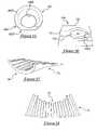
- FIG. 7is a diagrammatic illustration of a base plate of the apparatus of FIG. 1 , according to an embodiment of the present invention.
- FIG. 8is a diagrammatic illustration of a well of the apparatus of FIG. 1 , according to an embodiment of the present invention.
- FIG. 9is a diagrammatic illustration of an ejector of the apparatus of FIG. 1 , according to an embodiment of the present invention.
- FIG. 10is a diagrammatic illustration of a side view of the ejector of the apparatus of FIG. 9 , according to an embodiment of the present invention.
- FIG. 11is a diagrammatic illustration of a side view of the base plate side of FIG. 7 ;
- FIG. 12is a diagrammatic illustration of an exploded view of a solenoid of the apparatus of FIG. 1 , according to an embodiment of the present invention
- FIG. 13is a diagrammatic illustration of the solenoid of the apparatus of FIG. 12 ;
- FIG. 14is a diagrammatic illustration of a collector of the apparatus of FIG. 1 , according to an embodiment of the present invention.
- FIG. 15is a diagrammatic illustration of a guide of the apparatus of FIG. 1 , according to an embodiment of the present invention.
- FIG. 16is a diagrammatic illustration of a receptor of the apparatus of FIG. 1 , according to an embodiment of the present invention.
- FIG. 17is a diagrammatic illustration of a rack for use with the apparatus of FIG. 1 , according to an embodiment of the present invention.
- FIG. 18is a second diagrammatic illustration of the rack of FIG. 17 .
- the present inventionprovides an apparatus or sorting device 10 for receiving and sorting disks 12 .
- the disks 12have a parameter.
- the disks 12may be differentiated by the value of the parameter.
- the disks 12may be gaming chips, which typically have different colors representing different monetary values.
- the present inventionis not limited to the parameter being color. Any type of parameter that may be sensed or detected to distinguish and separate disks may be used.
- the parametermay be, but is not limited to, one of color, an image, bar code (or other discernible pattern), or RFID created by an embedded integrated circuit (IC) chip.
- the apparatus 10includes a housing 14 which in the illustrated embodiment, includes a frame 16 having a circular cross-section.
- the frame 16may be covered by a flexible protective cover 18 .
- the apparatus 10also includes a wheel 20 and a motor 22 coupled to the frame 16 and the wheel 20 .
- the wheel 20includes at least one hole forming a well (see below) for receiving one of the disks 12 .
- the wheel 20is rotatably coupled to the frame 16 and is rotated about an axis 24 (see FIG. 2 ) by the motor 22 .
- a disk parameter sensor 26is coupled to the frame 16 and positioned relative to the well.
- the sensor 26senses a value of the parameter of the disk 12 in one of the wells and responsively generates a parameter value signal as a function of the value.
- the sensor 26is dependent upon the nature of the parameter.
- the parameteris color and the sensor 26 is a color sensor.
- the sensor 26may be a digital image sensor, a bar code reader, or RFID detector, or any other suitable sensor for sensing, detecting or reading the value of the parameter.
- the sensor 26is a color sensor, but the present invention is not limited to such.
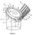
- the apparatus 10further includes a collecting device 28 coupled to the frame 16 and positioned relative to the wheel 20 .
- the collecting device 28includes a collecting device assembly 29 having a first end 29 A and a second end 29 B.
- the collecting device 28includes a plurality of collectors 30 (see FIG. 2 ).
- each collector 30has first and second ends.
- the first ends of the plurality of collectors 30are aligned with the first ends 29 A of the collecting device assembly 29 .
- the second ends of the plurality of collectors 30are aligned with the second ends 29 B of the collecting device assembly 29 .
- the first ends of the plurality of collectors 30are arranged in a semi-circle having a first radius.
- the collecting device 28is a rack 32 and the plurality of collectors 30 are column assemblies 34 .
- the rack 32is described more fully below.
- the plurality of collectors 30may be individual bags (not shown) connected to the frame 16 which are positioned relative to the wheel 20 for collecting the disks 12 as the disks 12 are ejected (see below).
- At least one ejector 36is coupled to the frame 16 and positioned relative to the well (see below). The ejector 36 ejects the disk 12 from the well in response to receiving an eject signal.
- a controller 38is coupled to the disk parameter sensor 26 and the ejector 36 .
- the controller 38receives the parameter value signal and responsively sends an eject signal to the ejector 36 to eject the disk 12 from the well into the first collector 30 when the parameter value signal has a first value and for sending an eject signal to the ejector 36 to eject the disk 12 from the well into the second collector 30 when the parameter value signal has a second value.
- the plurality of collectors 30are spaced apart at a predetermined angle, e.g., 15 degrees.
- the apparatus 10may include a position sensor 40 .
- the position sensor 40is coupled to the frame 16 and senses the relative position of the wheel 20 as it rotates.
- the position sensor 40generates a position signal, which is delivered to the controller 38 (see below).
- the apparatus 10may include a motor position sensor 22 A for sensing a position of the motor 22 (see below).
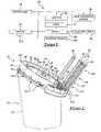
- the gaming chips 52are flat disks, which only differ from one another by their color and/or value.
- the sorting device 50is built in such a way that it may be positioned next to the dealer at the gaming table (not shown). This allows the dealer to rake or move the gaming chips 52 into a storage compartment 54 and pick up stacks of sorted chips 52 in batches of twenty or other pre-determined amounts, and place them onto the table before handing them out to the players.
- the sorting device 50has a feed 56 into the storage compartment 54 that may also serve as a cover.
- a wheel 58rotates inside the storage compartment 54 .
- the wheel 58has a plurality of holes 60 spaced apart. In the illustrated embodiment, the wheel 58 has eighteen holes 60 spaced 20 degrees apart.
- each of the holes 60 in the wheel 58a well 62 is attached.
- the wells 62immediately absorb or accept the chips 52 dropped from the storage compartment 54 .
- Each well 62has an ejector compartment 104 .
- the wheel 58may also include a plurality of studs 64 located adjacent the plurality of holes 60 on the wheel 58 .
- the plurality of studs 64 on the wheel 58assist in evenly distributing the chips 52 on the wheel 58 .
- one or more chip reflector plates 66may be mounted to the edge of the wheel 58 .
- the straight corners of the chip reflector plate 66assist in the distribution of the chips 52 and avoid endless “running” of the chips 52 along the edge of the wheel 58 .
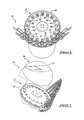
- the bottom of the wheel 58shows the eighteen attached wells 62 .
- Each well 62has an associated ejector lever 68 , which is movable between first and second positions.
- the first positionis shown in FIGS. 6 and 9 is the default position, i.e., pointing towards the center of the wheel 58 .
- each ejector lever 68pivots about a pivot point 68 A.
- the ejector lever 68is shown in the first or default position. As described below, the ejector lever 68 may be pivoted about the pivot point 68 A in a counter-clockwise direction towards the second position to eject a chip 52 in the associated well 62 .
- the wheel 58has an upper surface 58 A and a bottom surface 58 B.
- a large sprocket wheel 70is mounted to the bottom surface 58 B of the wheel 58 .
- An axle 72is mounted at the center of the wheel 58 .
- the apparatus or sorting device 10may also include a base plate 74 mounted to the frame 16 .
- the base plate 74has an aperture 76 .
- a shaft 78is disposed within the aperture 76 and has an inner bore 80 .
- the axle 72slides into the inner bore 80 of the shaft 78 at the base plate 74 so that the wheel 58 may rotate.
- the sprocket wheel 70is used to drive the wheel 58 forward by a drive gear 82 of a motor 83 , such as a stepper motor, fixed to the base plate 74 .
- metal reference pins 84are placed at the bottom of the wheel 58 to monitor the position of the wells 62 relative to the collecting device 28 (see below), which are placed at fixed positions on the base plate 74 , outside the circumference of the wheel 58 .
- each well or ejector compartment 62has an associated metal reference pin 84 mounted thereto as a reference.
- the metal reference pins 84are spaced 20 degrees apart since the wells 62 are spaced 20 degrees apart.
- the metal reference pins 84are detected by a synchronization sensor 94 such as a hall effect sensor, as the wheel 58 rotates.
- the motor position sensor 22 Amay be an encoder mounted adjacent the motor 83 , 22 .
- 1-degree reference pointsare measured directly from the motor position sensor 22 A or encoder. The data collected from these reference points is used to determine when an ejector compartment 104 is aligned with a collector 30 of the collecting device 28 (which is every five degrees) so that, when needed, a chip 52 can be ejected from the well 62 into a collector 30 .
- Each well 62includes a bottom plate 88 .
- Each bottom plate 88includes a small slotted cutout 90 .
- a color sensor 92is mounted to the base plate 74 and reads the chip 52 when it passes the color sensor 92 .
- the color sensor 92 and the synchronization sensor 94is mounted to the bottom surface 58 B of the base plate 74 adjacent an associated aperture 96 , 98 .
- the motor position sensor 22 Asenses each 1-degree of movement of the motor 22 , 83 and generates 1-degree reference point signals.
- the shape of the wells 62is such that the diameter at the top 100 (the part of the well 62 attached to the wheel 58 ), is larger then the diameter at the bottom 102 . This creates a funnel that facilitates the collection of the chips into a stack in the well 62 .
- the ejector compartment 104can just hold one chip 52 and is located at the bottom of each well 62 .
- chips 52are ejected from the ejector compartment 104 .
- the chips 52will, after a few turns of the wheel 58 , fill up the wells 62 . Since the wheel 58 rotates constantly, the plurality of studs 64 assist with the distribution of the chips 52 .
- the first chip 52 that falls into an empty well 62will land at the bottom part of the well, i.e., the ejector compartment 104 .
- each ejector compartment 104has an associated ejector lever 68 .
- a spring 106biases the ejector lever 68 to the default position.
- a retention clip 108 , second spring 110 , and a rubber stop 112are arranged to absorb the sound of the returning ejector lever 68 .
- the retention clip 108retains the chip 52 from falling out of the ejector compartment 104 as the wheel 58 is rotating.
- the collecting device 28is a rack 32 which includes a rack assembly 116 .
- the rack assembly 116includes a plurality of column assemblies 118 and a rack base portion 120 .
- the rack assembly 116has nine column assemblies 118 .
- the ejector lever 68pushes the chip 52 out of the ejector compartment 104 into one of the nine column assemblies 118 , which are mounted at a fixed position on the base plate 74 via the rack base portion 120 .
- a flattened edge 122 of the ejector compartment 104forces the chip 52 into one of the column assemblies 118 .
- the base plate 74is placed at an angle to allow the chips 52 in the storage compartment 54 to drop directly onto the rotating wheel 58 .
- the shaft 78 in the center of the base plate 74will accept the wheel axle 72 .
- nine push-type solenoids 124are mounted to the base plate 74 . Also mounted to the base plate 74 are the rack assembly 116 , the motor 22 , the synchronization sensor 94 , the color sensor 92 and the motor position sensor 22 A. An empty well sensor (not shown) may also be mounted to the base plate 74 .
- the rack base portion 120forms nine receptors 126 .
- the centers of the nine receptors 126are 15 degrees apart in the bottom half of the wheel 58 . Such spacing allows the column assemblies 118 which are mounted on top of the receptors 126 , to be placed as close together as possible, limiting the circular arm motion of the dealer when he needs to remove chips 52 from the column assemblies 118 .
- the solenoids 124are also placed 15 degrees apart in a direct line with the receptors 126 .
- the drive gear 82drives the large sprocket wheel 70 . While the wheel 58 and the attached wells 62 are continuously rotating, the base plate 74 and the affixed solenoids 124 , receptors 126 and sensors 92 , 94 and 22 A remain in their fixed position.
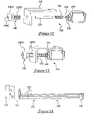
- each solenoid 124is mounted on a bracket 128 by an appropriate fastener (not shown).
- a shaft 130 of the push-type solenoid 124is extended with a small plunger 132 .
- Two nuts 134 on the shaft 130allow for adjustment of the stroke length.
- a nylon washer 136is also mounted on the solenoid shaft 130 on which a spring 138 rests. The spring 138 will accelerate the plunger 132 in moving back to its default position when the solenoid 124 is deactivated.
- the plunger 132moves through a shaft nut 140 which is screwed into the base plate 74 .
- the shaft nut 140provides operational stability.
- the shaft nut 140includes a head portion 140 A and a threaded portion 140 B.
- the threaded portion 140 Bis threaded through an aperture in the base plate 74 (not shown) and an aperture 128 A in the bracket 128 , such that the head portion 140 A is on an upper surface of the base plate 74 (see FIG. 7 ).
- the plunger 132extends through a bore 140 C of the shaft nut 140 , past the base plate 74 and the head 140 A of the shaft nut 140 .
- a solenoid 124is activated only when there is a space in between any two ejector levers 68 that are in rotation above it. As the wheel 58 rotates, when a solenoid 124 is activated, the ejector lever 68 makes contact with the plunger 132 of the solenoid 124 , which causes the ejector lever 68 to move to its outermost pivotal point (the second position) thereby simultaneously forcing the chip 52 out of the ejector compartment 104 . The timing of the ejection of the chip 52 is determined by the synchronization sensor 94 , and the controller 38 (see below).
- each column assembly 118includes one of the receptors 126 , a chip guide 142 , a column 144 , and an end cap 146 .
- the receptors 126 and chip guides 142form the rack base portion 120 .
- Each column 144is made from three column rods 148 as shown.
- the rack 32is unitarily formed (see FIGS. 17 and 18 ).
- the bottom of the receptor 126is level with the bottom of the ejector compartment 104 .
- the receptor 126has a flange 150 at the bottom that forces a chip 52 to become wedged under the other chips 52 that are stored above it in the chip guide 142 and the column 144 .
- the inside 142 B of the chip guide 142is shaped like a funnel to assist in the alignment of the chips 52 into the column 144 .
- the bottom 142 A of the chip guide 142is larger in diameter than the top 142 D of the chip guide 142 .
- a cut-out 142 C at the bottom 142 A of the chip guide 142 and the top of a reflector 126 Ais required to allow a cam 152 to pass.
- the chip guide 142also has a cut-out at the top 142 D to allow the chip reflector plates 66 to pass.
- the end cap 146not only contains the column rods 148 which form the column 144 , but may also contain a small Hall effect sensor built in that is used to sense a “column full” condition.
- the chip color or value sensor 92which is mounted to the base plate 74 , determines the chip's identity through the small cutout 79 in the bottom plate 88 of the ejector compartment 104 . All data from the sensors 92 , 94 , 22 A is processed by the controller 38 , which, based upon the color value read, activates the appropriate solenoid 124 to discharge and consequently eject the chip 52 into the corresponding column assembly 118 .
- a small additional sensormay be used to monitor the empty status of all the wells 62 . No ejection will take place if the well 62 is empty.
- the synchronization sensor 94is mounted at the base plate 74 (the “Sync A” sensor) and the motor position sensor 22 A is mounted at the stepper motor 83 (the “Sync B” sensor).
- the Sync A sensor 94monitors the metal reference pins 84 mounted to the ejector compartment 104 . Every 20 degrees a metal reference pin 84 passes the sensor 94 and a Sync A pulse is generated.
- the Sync B sensor 22 Agenerates a pulse for every 1 degree rotation of the wheel.
- the plurality of holes 60 on the wheel 58are placed 20 degrees apart and the receptors 126 are placed 15 degrees apart. Columns are numbered column 1 through column 9 . Column 1 is the left-most column and the Sync A sensor 94 is placed at 20 degrees forward of column 1 .
- hole 60 (n)is positioned in front of the receptor 126 at column 1
- hole (n+3) 60will be positioned in front of the receptor 126 at column 5
- hole (n+6) 60will be positioned in front of the receptor 126 at column 9 . Every 20 degrees (Sync A signal) that the wheel rotates, the next hole (n+1) 60 will be positioned in front of the receptor 126 at position 1 , and so on.
- the alignment of a hole 60 in front of ejector column 1happens with the Sync A signal.
- the Sync A sensor 94is positioned exactly at that point that the solenoid 124 needs to be activated so that the ejector lever 68 will push the chip 52 into the receptor 126 of column 1 .
- hole (n+1) 60is now aligned with the receptor 126 of column 2 and at the same time hole (n+4) 60 is aligned with the receptor 126 of column 6 .
- hole (n+2) 60is now aligned with the receptor 126 of column 3 and at the same time hole (n+5) 60 is now aligned with the receptor 126 of column 7 .
- hole (n+3) 60is now aligned with the receptor 126 of column 4 and at the same time hole (n+6) is aligned with the receptor 126 of position 8 .
- hole (n+4) 60is aligned with the receptor 126 of column 5 and hole (n+7) 60 is aligned with the receptor 126 at column 9 .
- holes 1 , 5 , and 9are separated by a multiple of 20 degrees, at any time hole 1 is aligned with a receptor 126 , holes 5 and 9 are also aligned with a receptor 126 .
- holes 2 and 6are separated by a multiple of 20 degrees, at any time, hole 2 is aligned with a receptor 126 , hole 6 is also aligned with a receptor 126 .
- holes 3 and 7 and for holes 4 and 8are also aligned with a receptor 126 .
- the respective solenoids 124are activated when the respective chip color of a chip 52 in the respective ejector compartment 104 matches a pre-assigned color of the destination column assembly 118 . This assists in increasing the sorting efficiency.
- the solenoid 124will be activated if the color of the chip 52 in the ejector compartment 104 matches the pre-assigned color of a destination column assembly 118 , which will result in its plunger 132 moving upwards from the base plate 74 .
- the solenoid 124is activated by the controller 38 at a point in time when the next-arriving ejector compartment 104 contains the appropriate-colored chip 52 . Since the wheel 58 is continuously moving, the result is that the ejector lever 68 will be hit by the top of the plunger 132 of the solenoid 124 and will continue to extend outwards from its pivot point 68 A for the duration of contact with the plunger 132 . The ejector lever 68 is curved in such a way that the chip 52 will be pushed out as fast as possible. When the solenoid 124 is deactivated its plunger 132 drops back down rapidly.
- the ejector lever 68will then move back to its default position by means of the spring 138 , ready for the next ejection action.
- the ejector lever 68will push the chip 52 more than 50% out of the ejector compartment 104 into the receptor 126 . Since the wheel 58 is still turning, and the chip 52 is already more than 50% out of the ejector compartment 104 into the receptor 126 , the momentum of the wheel 58 will push the chip 52 into the receptor 126 , aided by the flattened edge 122 of the ejector compartment 104 .
- the shape of the flange 150forces the chip 52 to become wedged underneath the stack of chips 52 already in place. This in turn forces the previously positioned chips 52 upwards.
- the exit section 154 of the ejector compartment 104is taller then the thickness of the chip 52 to allow the chip 52 to move sufficiently upwards without jamming the wheel 58 (see FIG. 10 ).
- the number of chips 52 that can be pushed upis limited by the power that the driving mechanism can provide, relative to the weight of the chips 52 in the column assembly 118 .
- the sprocket wheel 70 to motor sprocket wheel ratio of 17.14/1provides the necessary force to push the column of chips 52 up without any difficulties.
- a practical limit of 100 chips 52 per columnhas been chosen, but the design allows for easy extension of the columns.
- the chip guide 142assists with the alignment of the chips 52 into the column assemblies 118 .
- the small cam 152is mounted at the outside of each well 62 on the chip reflector plates 66 in order to assist with the alignment of the stacked chips 52 in the bottom of the receptor 126 .
- the color sensor 92reads the value of the gaming chip 52 and determines into which of the nine column assemblies 118 , the chip 52 needs to be ejected.
- the color associated with a column assembly 118is determined by placing the sorting device 50 in a “training mode.” The wheel 58 needs to be empty before the training mode is started. Once in the training mode, the color of the first chip 52 that is dropped into the sorting device 50 will be stored as the associated or pre-defined color assigned to column 1 . After that, the second chip 52 is dropped into the device 10 . The color of the second chip 52 is read and assigned to the second column assembly 118 , and so on.
- a method for receiving and sorting disks 12 having a parameteris provided.
- the parameter of each disk 12has one of a plurality of values.
- the methodincludes the steps of rotating the wheel 20 .
- the wheel 20includes at least one well 62 for receiving a disk 12 .
- the methodalso includes the steps of receiving a first disk 12 in a first well 62 and sensing the value of the parameter of the first disk 12 .
- the methodfurther includes the step of ejecting the first disk 12 into one of a plurality of collectors 30 when the first well 62 is aligned with the one collector 30 and the value of the parameter of the first disk 12 is equal to a value associated with the one collector 30 .
- the wheel 20may include additional wells 62 for receiving additional disks 12 .
- the value of the parameter of the disks 12 received in the additional wells 62are sensed and the disks 12 are ejected into a collector 30 based on color.
- Disks 12 in different wells 62may be ejected into a respective collector 30 substantially simultaneously.
- Disks 12are sorted and ejected into nine column assemblies 118 spaced at 20 degree intervals. Furthermore, as discussed above, whenever the first column assembly 118 , i.e., column 1 , is aligned with a well 62 , so are columns 5 and 9 . Likewise, columns 2 and 6 , columns 3 and 7 , and columns 5 and 9 are aligned with wells 62 at the same time.
- any set or subset of wells 62are aligned with column assemblies 118 and contain a chip whose parameter has a value equal to the value associated with the column assembly 118 to which it is aligned, the chips 52 in the set or sets of wells 62 may be ejected at the same time.
- the sorting deviceis compact, as it is designed using a rotating circular plate placed at an angle.
- This platecontains eighteen holes which are slightly larger than a chip, and each hole has a well or reservoir attached to it in the shape of a funnel to efficiently absorb the influx of gaming chips.
- the funnelallows the chips to align themselves easily.
- the advantage of the wellsis that it pre-stores the chips and hence allows the device to be more compact and efficient. There is no practical limit to the size of the wells or the number of chips it can store.
- sorting of chipsis accomplished by the use of a plunger that pushes the gaming chips from a conveyor belt upwards in order to stack them into their appropriate column.
- the first problem with this methodis that knives are used to separate the chips from the conveyor belt in order to be pushed up into the column. These knives need to be frequently replaced.
- This inventionaccomplishes the sorting and stacking with one single movement, which dramatically reduces the complexity and size of the device. This is to the benefit of the operator.
- the second problem with previous devicesis that the gaming chips fall initially into a chamber or receptacle before they come into contact with the “transporting” device (i.e., the conveyer belt). This causes the chips to get stuck between the immobile chamber and the moving belt and jam the machine. With the new invention, all the chips fall directly onto the moving part (i.e., the rotating disk), so there is no possibility of interference from being transferred to an additional mechanism.
- the “transporting” devicei.e., the conveyer belt
- the number of receptorsis configurable and can be equal to the number of wells in the wheel. Due to the fact that the receptors are positioned around and outside the disk, and the disk may be suspended with a minimal footprint, ergonomic advantages, from an operational perspective, are dramatically increased.
- the 135 degree circleallows the dealer to stand either to the side, or directly behind the machine, to reach the gaming chips and also the table simultaneously.
- any chip entering any columnis subject to gravitational force, thus allowing the radius of the entire column array to be spread along a more lateral and flatter plane than the semi-circular shape of the wheel (in a smooth V-shape rather than a conventional U-shape).
- This optionpermits easier access to the individual columns, and reduces the distance between the bottom-most column and the table edge, by allowing the machine to be placed further under the table than would be allowed with a perfect semi-circular shape.
- the inventionalso allows for separation by either directly stacking the disk-like articles in columns in an upward motion or directly dropping them into any form of receptacle using gravity.
- An example of thisis a coin-sorting device by which coins are separated and dispensed appropriately.
- the devicemay be used in card rooms, for sorting chips into bags, boxes or other receptacles.
- the deviceuses the natural inertia of the wheel to complete the ejection of a chip outside its original trajectory (unlike the Chipper Champ—above its original trajectory).
- the lateral ejection methodapplies pressure along the entire half-circumference of the chip, thereby ensuring contact with the chip's most solid surface (unlike the Chipper Champ which applies pressure at vulnerable underside of chip).
- the chipsfall directly onto the rotating surface of the sorting apparatus (unlike the Chipper Champ which contains incoming chips into a hopper before transferring them to the ejecting device—their conveyor belt).
- the wheelis a one-piece-manufactured body, it is impossible for any movement or space differential between the wells, thus eliminating any potential timing errors (unlike the Chipper Champ, where there are continual spacing and consequential timing differentials between cups and segments).
- the circular shape and the outward angle of the column arrayallows the dealer's arm access to all the columns in the same plane (unlike the Chipper Champ where the dealer must physically reposition his body to access the outermost columns).
- the footprintis small, and thus there is no impediment to the dealer's feet (unlike the Chipper Champ, where the machine sits on the floor and occupies dealer foot space).
- the machineBecause the machine is compact, it can be located entirely under the table without the need for a section to be cut out (unlike the Chipper Champ where the bulkiness of the machine necessitates a cut-out in the table to maintain proximity).
- the dealeronly has to rotate the chips through approximately 90 degrees to grasp a stack of chips (unlike the Chipper Champ—approximately 180 degrees).
- ChipperWheelweighs about half of Chipper Champ.
- ChipperWheelis about half the mass of Chipper Champ.
- ChipperWheelejects chips laterally from the wheel to the column base, there is no need for an ancillary device between the two elements (unlike the Chipper Champ which necessitates knives).
- ChipperWheel chipscan be gravity-stacked downwards (unlike Chipper Champ which only has an upward option).
- ChipperWheel wellshave multi-chip capacity (unlike the Chipper Champ-single chip capability only).
- the ChipperWheelcan be rotated on differing horizontal angles, allowing greater operational flexibility (unlike the Chipper Champ which has a fixed angle).
- ChipperWheeluses only one shaft, unlike the Chipper Champ, whose belt revolves around three separate shafts.
Landscapes
- Physics & Mathematics (AREA)
- General Physics & Mathematics (AREA)
- Automatic Analysis And Handling Materials Therefor (AREA)
- Specific Conveyance Elements (AREA)
- Combined Means For Separation Of Solids (AREA)
Abstract
Description
Claims (20)
Priority Applications (7)
| Application Number | Priority Date | Filing Date | Title |
|---|---|---|---|
| US11/682,132US7681708B2 (en) | 2003-02-03 | 2007-03-05 | Apparatus for sorting articles |
| US12/729,577US8298052B2 (en) | 2003-02-03 | 2010-03-23 | Apparatus for sorting articles |
| US13/662,665US8678164B2 (en) | 2003-02-03 | 2012-10-29 | Apparatus for receiving and sorting disks |
| US14/222,307US9330516B2 (en) | 2003-02-03 | 2014-03-21 | Apparatus for receiving and sorting disks |
| US15/066,786US9589407B2 (en) | 2003-02-03 | 2016-03-10 | Apparatus for receiving and sorting disks |
| US15/442,027US9990792B2 (en) | 2003-02-03 | 2017-02-24 | Methods and apparatus for receiving and sorting disks |
| US16/000,016US10706656B2 (en) | 2003-02-03 | 2018-06-05 | Methods and apparatus for receiving and sorting disks |
Applications Claiming Priority (4)
| Application Number | Priority Date | Filing Date | Title |
|---|---|---|---|
| US44417803P | 2003-02-03 | 2003-02-03 | |
| US10/742,722US6976589B2 (en) | 2003-02-03 | 2003-12-19 | Apparatus for sorting articles |
| US11/069,426US7201268B2 (en) | 2003-02-03 | 2005-03-01 | Apparatus for sorting articles |
| US11/682,132US7681708B2 (en) | 2003-02-03 | 2007-03-05 | Apparatus for sorting articles |
Related Parent Applications (1)
| Application Number | Title | Priority Date | Filing Date |
|---|---|---|---|
| US11/069,426ContinuationUS7201268B2 (en) | 2003-02-03 | 2005-03-01 | Apparatus for sorting articles |
Related Child Applications (1)
| Application Number | Title | Priority Date | Filing Date |
|---|---|---|---|
| US12/729,577ContinuationUS8298052B2 (en) | 2003-02-03 | 2010-03-23 | Apparatus for sorting articles |
Publications (2)
| Publication Number | Publication Date |
|---|---|
| US20070209975A1 US20070209975A1 (en) | 2007-09-13 |
| US7681708B2true US7681708B2 (en) | 2010-03-23 |
Family
ID=32776214
Family Applications (10)
| Application Number | Title | Priority Date | Filing Date |
|---|---|---|---|
| US10/742,722Expired - LifetimeUS6976589B2 (en) | 2003-02-03 | 2003-12-19 | Apparatus for sorting articles |
| US11/069,091Expired - LifetimeUS7028826B2 (en) | 2003-02-03 | 2005-03-01 | Apparatus for sorting articles |
| US11/069,426Expired - LifetimeUS7201268B2 (en) | 2003-02-03 | 2005-03-01 | Apparatus for sorting articles |
| US11/682,132Expired - LifetimeUS7681708B2 (en) | 2003-02-03 | 2007-03-05 | Apparatus for sorting articles |
| US12/729,577Expired - Fee RelatedUS8298052B2 (en) | 2003-02-03 | 2010-03-23 | Apparatus for sorting articles |
| US13/662,665Expired - LifetimeUS8678164B2 (en) | 2003-02-03 | 2012-10-29 | Apparatus for receiving and sorting disks |
| US14/222,307Expired - LifetimeUS9330516B2 (en) | 2003-02-03 | 2014-03-21 | Apparatus for receiving and sorting disks |
| US15/066,786Expired - Fee RelatedUS9589407B2 (en) | 2003-02-03 | 2016-03-10 | Apparatus for receiving and sorting disks |
| US15/442,027Expired - LifetimeUS9990792B2 (en) | 2003-02-03 | 2017-02-24 | Methods and apparatus for receiving and sorting disks |
| US16/000,016Expired - Fee RelatedUS10706656B2 (en) | 2003-02-03 | 2018-06-05 | Methods and apparatus for receiving and sorting disks |
Family Applications Before (3)
| Application Number | Title | Priority Date | Filing Date |
|---|---|---|---|
| US10/742,722Expired - LifetimeUS6976589B2 (en) | 2003-02-03 | 2003-12-19 | Apparatus for sorting articles |
| US11/069,091Expired - LifetimeUS7028826B2 (en) | 2003-02-03 | 2005-03-01 | Apparatus for sorting articles |
| US11/069,426Expired - LifetimeUS7201268B2 (en) | 2003-02-03 | 2005-03-01 | Apparatus for sorting articles |
Family Applications After (6)
| Application Number | Title | Priority Date | Filing Date |
|---|---|---|---|
| US12/729,577Expired - Fee RelatedUS8298052B2 (en) | 2003-02-03 | 2010-03-23 | Apparatus for sorting articles |
| US13/662,665Expired - LifetimeUS8678164B2 (en) | 2003-02-03 | 2012-10-29 | Apparatus for receiving and sorting disks |
| US14/222,307Expired - LifetimeUS9330516B2 (en) | 2003-02-03 | 2014-03-21 | Apparatus for receiving and sorting disks |
| US15/066,786Expired - Fee RelatedUS9589407B2 (en) | 2003-02-03 | 2016-03-10 | Apparatus for receiving and sorting disks |
| US15/442,027Expired - LifetimeUS9990792B2 (en) | 2003-02-03 | 2017-02-24 | Methods and apparatus for receiving and sorting disks |
| US16/000,016Expired - Fee RelatedUS10706656B2 (en) | 2003-02-03 | 2018-06-05 | Methods and apparatus for receiving and sorting disks |
Country Status (3)
| Country | Link |
|---|---|
| US (10) | US6976589B2 (en) |
| EP (1) | EP1624976A4 (en) |
| WO (1) | WO2004069431A2 (en) |
Cited By (6)
| Publication number | Priority date | Publication date | Assignee | Title |
|---|---|---|---|---|
| US20100230233A1 (en)* | 2003-02-03 | 2010-09-16 | Shuffle Master Gmbh & Co Kg | Apparatus for sorting articles |
| US20110207390A1 (en)* | 2002-06-05 | 2011-08-25 | Ernst Blaha | Chip stack cutter devices for displacing chips in a chip stack and chip-stacking apparatuses including such cutter devices, and related methods |
| US20110306284A1 (en)* | 2002-06-05 | 2011-12-15 | Shuffle Master Gmbh & Co Kg | Chip-sorting device with chip removal units |
| US8336699B2 (en) | 2009-11-02 | 2012-12-25 | Shuffle Master Gmbh & Co Kg | Chip sorting devices, components therefor and methods of ejecting chips |
| US9836909B2 (en)* | 2016-04-06 | 2017-12-05 | Shuffle Master Gmbh & Co Kg | Chip sorting devices and related assemblies, components and methods |
| US10096192B1 (en) | 2017-08-30 | 2018-10-09 | Shuffle Master Gmbh & Co Kg | Chip sorting devices and related assemblies and methods |
Families Citing this family (19)
| Publication number | Priority date | Publication date | Assignee | Title |
|---|---|---|---|---|
| US20160136511A9 (en) | 2002-05-20 | 2016-05-19 | Bally Gaming, Inc. | Four Card Poker Game with Variable Wager |
| US20060284376A1 (en) | 2005-06-17 | 2006-12-21 | Shuffle Master, Inc. | Casino table variant of Texas hold'em poker |
| US20090315264A1 (en)* | 2004-09-10 | 2009-12-24 | Snow Roger M | Seven-card poker game with pot game feature |
| US8540548B2 (en)* | 2010-10-04 | 2013-09-24 | Tech 4 Kids, Inc. | Child's activity toy and disc dispenser therefor |
| US8512116B2 (en) | 2011-08-22 | 2013-08-20 | Shfl Entertainment, Inc. | Methods of managing play of wagering games and systems for managing play of wagering games |
| CN103920650B (en)* | 2014-03-19 | 2016-01-13 | 浙江歌瑞新材料有限公司 | A kind of automatic detection device |
| CN104103126B (en)* | 2014-08-08 | 2016-09-28 | 江苏科思机电工程有限公司 | A kind of Coin cleaning-sorting machine |
| CN104190631A (en)* | 2014-08-21 | 2014-12-10 | 苏州佳视佳机械科技有限公司 | Sequential connecting shackle collection device |
| JP6337275B2 (en)* | 2015-06-09 | 2018-06-06 | 旭精工株式会社 | Coin hopper |
| CN106067211A (en)* | 2016-07-31 | 2016-11-02 | 宁德师范学院 | A kind of intelligence stagewise Coin sorting device |
| WO2018025622A1 (en)* | 2016-08-02 | 2018-02-08 | エンゼルプレイングカード株式会社 | Inspection system and management system |
| WO2018073637A1 (en)* | 2016-10-18 | 2018-04-26 | Robert Bosch Gmbh | Container lid loading apparatus |
| US10839651B2 (en)* | 2016-11-11 | 2020-11-17 | Smart Industries Corporation | Arcade game with RFID reader |
| CN108961529A (en)* | 2018-07-02 | 2018-12-07 | 苏州浪潮智能软件有限公司 | A kind of sorting device and method of chip card |
| US10621816B2 (en)* | 2018-07-24 | 2020-04-14 | Gametec International Limited | Gaming tables for roulette and similar games |
| CN109993876A (en)* | 2019-04-23 | 2019-07-09 | 苏州少士电子科技有限责任公司 | A kind of Coin cleaning-sorting machine |
| CN110125050B (en)* | 2019-05-17 | 2021-03-26 | 福州派利德电子科技有限公司 | Integrated circuit chip testing taping machine good product collecting device and method |
| CN110694915B (en)* | 2019-10-30 | 2021-04-16 | 中国科学技术大学 | An e-commerce object sorting platform |
| US11021286B1 (en)* | 2021-01-05 | 2021-06-01 | Performance Feeders, Inc. | Receptacle feeding system |
Citations (84)
| Publication number | Priority date | Publication date | Assignee | Title |
|---|---|---|---|---|
| AT6405B (en) | 1900-12-11 | 1902-01-10 | Wladyslaw Pruszkowski | |
| AT6546B (en) | 1900-12-21 | 1902-01-25 | Heinrich Titze | |
| US1813296A (en) | 1927-03-14 | 1931-07-07 | Arthur C Kidwell | Coin separator |
| US1947456A (en) | 1931-11-28 | 1934-02-20 | Sattley Company | Coin handling machine |
| US2904151A (en)* | 1957-01-30 | 1959-09-15 | Lloyd F Brogan | Escrow device for coin operated mechanisms |
| US3143118A (en) | 1960-09-26 | 1964-08-04 | Vacuumatic Ltd | Coin sorting apparatus |
| US3371761A (en) | 1966-05-04 | 1968-03-05 | Ryo Hirano | Apparatus for discriminating hard coins |
| US3583410A (en) | 1969-04-25 | 1971-06-08 | Jack E Bayha | Payout mechanism for coin change dispensing apparatus |
| US3680566A (en) | 1969-09-22 | 1972-08-01 | Micro Magnetic Ind Inc | Bulk coin dispenser |
| US3766452A (en) | 1972-07-13 | 1973-10-16 | L Burpee | Instrumented token |
| US3771538A (en) | 1971-07-26 | 1973-11-13 | K Reis | Coin sorting and counting machines |
| US3827582A (en) | 1971-12-13 | 1974-08-06 | G Lederer | Stacking device |
| US4157139A (en)* | 1976-12-28 | 1979-06-05 | Bertil Knutsson | Apparatus for sorting and/or handling disc-like members |
| GB2061490A (en) | 1979-10-17 | 1981-05-13 | Harwood H L | Sorting Coloured Gambling Chips |
| US4275751A (en) | 1979-05-10 | 1981-06-30 | Brandt, Inc. | Coin sorter with expanded capability |
| US4360034A (en) | 1980-04-09 | 1982-11-23 | Joseph C. Gianotti, Trustee | Coin sorter-counter |
| US4531531A (en) | 1980-11-18 | 1985-07-30 | Ristvedt-Johnson, Inc. | Coin handling machine |
| US4543969A (en) | 1983-05-06 | 1985-10-01 | Cummins-Allison Corporation | Coin sorter apparatus and method utilizing coin thickness as a discriminating parameter |
| US4607649A (en) | 1983-12-21 | 1986-08-26 | Brandt, Inc. | Coin sorter |
| US4681128A (en) | 1986-06-23 | 1987-07-21 | Ristvedt Victor G | Coin sorter |
| US4731043A (en) | 1983-12-14 | 1988-03-15 | Ristvedt-Johnson, Inc. | Coin sorter |
| US4775354A (en) | 1987-06-29 | 1988-10-04 | Cummins-Allison Corp. | Coin sorting apparatus with rotating disc stationary guide plate for sorting coins by their different diameters |
| GB2203582A (en) | 1987-04-16 | 1988-10-19 | Leonard Marmaduke Steele | Coin sorting apparatus |
| US4863414A (en) | 1986-06-23 | 1989-09-05 | Ristvedt Victor G | Coin sorter |
| US4966570A (en) | 1987-07-30 | 1990-10-30 | Ristvedt Victor G | Coin sorting apparatus for sorting coins of selected denominations |
| EP0424355A1 (en) | 1989-10-16 | 1991-04-24 | Christian Pohanka | Device for sorting chips at game-tables |
| US5011455A (en) | 1990-02-12 | 1991-04-30 | Cummins-Allison Corporation | Coin sorter with automatic bag-switching |
| US5022889A (en) | 1986-06-23 | 1991-06-11 | Ristvedt Victor G | Coin sorter |
| US5042810A (en) | 1989-02-13 | 1991-08-27 | Technical Casino Services, Ltd. | Roulette apparatus |
| WO1991017842A1 (en) | 1988-11-23 | 1991-11-28 | Sjoestroem Erik | Sorting machine |
| WO1992011953A1 (en) | 1990-12-27 | 1992-07-23 | John Huxley Casino Equipment Ltd | Apparatus for sorting and stacking disc-like objects |
| US5141443A (en) | 1990-05-14 | 1992-08-25 | Cummins-Allison Corp. | Coin sorter with automatic bag-switching or stopping |
| GB2254419A (en) | 1991-08-06 | 1992-10-07 | Amusement Equip Co Ltd | Sorting of differently identified gaming chips |
| US5166502A (en) | 1990-01-05 | 1992-11-24 | Trend Plastics, Inc. | Gaming chip with implanted programmable identifier means and process for fabricating same |
| DE4240886A1 (en) | 1992-12-04 | 1994-07-21 | Deckert Carl Helmuth | Gambling chips/tokens with built-in bar code unit for games machines |
| CA2090073A1 (en) | 1993-02-22 | 1994-08-23 | Peter Brooke Lovelace Keate | Poker and other gaming chip cleaning and sanitizing device |
| EP0631260A2 (en) | 1993-06-22 | 1994-12-28 | Christian Pohanka | Device for centring chips on a stack |
| US5406264A (en) | 1994-04-18 | 1995-04-11 | Sensormatic Electronics Corporation | Gaming chip with magnetic EAS target |
| WO1995028996A1 (en) | 1994-04-26 | 1995-11-02 | Technical Casino Services Limited | A detection system |
| US5472074A (en) | 1994-03-09 | 1995-12-05 | Milcetic; Duncan J. | Coin operated dispensing machine |
| ITTO941040A1 (en) | 1994-12-20 | 1996-06-20 | Abbiati Casino Equipment S N C | COIN SELECTOR EQUIPMENT. |
| WO1996023281A1 (en) | 1995-01-24 | 1996-08-01 | Chipper 2000 (Isle Of Man) Limited | Colour detection apparatus |
| US5551542A (en) | 1993-12-13 | 1996-09-03 | Stockli; Rudolf | Process and apparatus for identifying coins |
| WO1996034258A1 (en) | 1995-04-28 | 1996-10-31 | Chipper 2000 (Isle Of Man) Limited | Colour detection method |
| US5624308A (en) | 1994-09-15 | 1997-04-29 | Standardwerk Eugen Reis Gmbh | System for sorting and/or counting coins by means of a circular sorting track |
| US5651548A (en) | 1995-05-19 | 1997-07-29 | Chip Track International | Gaming chips with electronic circuits scanned by antennas in gaming chip placement areas for tracking the movement of gaming chips within a casino apparatus and method |
| FR2749093A1 (en) | 1996-05-24 | 1997-11-28 | Bourgogne Grasset | Electronic management of casino roulette table |
| FR2752078A1 (en) | 1996-07-30 | 1998-02-06 | Gemplus Sca | Sorting of gaming chips used in casinos or gaming halls |
| US5735742A (en) | 1995-09-20 | 1998-04-07 | Chip Track International | Gaming table tracking system and method |
| US5755618A (en) | 1995-09-14 | 1998-05-26 | Grips Electronic Gmbh | Apparatus for storing coins or coin-like articles |
| US5770533A (en) | 1994-05-02 | 1998-06-23 | Franchi; John Franco | Open architecture casino operating system |
| US5781647A (en) | 1995-10-05 | 1998-07-14 | Digital Biometrics, Inc. | Gambling chip recognition system |
| US5827117A (en) | 1996-05-13 | 1998-10-27 | Mag-Nif Incorporated | Coin sorter and packager |
| US5865673A (en)* | 1996-01-11 | 1999-02-02 | Cummins-Allison Corp. | Coin sorter |
| US5895321A (en) | 1995-10-09 | 1999-04-20 | Etablissements Bourgogne Et Grasset | Gambling chip |
| GB2333632A (en) | 1998-01-23 | 1999-07-28 | Technical Casino Services Ltd | Disc sorting apparatus and method |
| US5947257A (en) | 1998-01-26 | 1999-09-07 | Schwartz; Melvin | Electronic coin counter for cashier station |
| US5950796A (en) | 1996-04-12 | 1999-09-14 | Asahi Seiko Kabushiki Kaisha | Apparatus for measuring a diameter of a disk body |
| US5957776A (en) | 1995-08-09 | 1999-09-28 | Table Trac, Inc. | Table game control system |
| EP0950989A1 (en) | 1998-04-14 | 1999-10-20 | Suzo International (NL) B.V. | Coin guiding device |
| WO1999060353A1 (en) | 1998-05-19 | 1999-11-25 | Active Silicon Limited | Method of detecting colours |
| US6021949A (en) | 1994-07-26 | 2000-02-08 | Etablissements Bourgogne Et Grasset | Gambling chip with identification device |
| US6080056A (en)* | 1997-12-22 | 2000-06-27 | Scan Coin Industries Ab | Coin handling apparatus and a coin deposit machine incorporating such an apparatus |
| US6186895B1 (en) | 1997-10-07 | 2001-02-13 | Mikohn Gaming Corporation | Intelligent casino chip system and method or use thereof |
| US6193599B1 (en)* | 1998-10-20 | 2001-02-27 | Asahi Seiko Co., Ltd. | Coin hopper device |
| US6260757B1 (en) | 1997-10-31 | 2001-07-17 | John M. Strisower | Automatic cashier machine |
| US6264109B1 (en) | 1997-03-10 | 2001-07-24 | Etablissements Bourgogne Et Grasset | Token with electronic chip |
| US6283856B1 (en) | 1999-03-12 | 2001-09-04 | Grips Electronics Ges. M.B.H | Patron and croupier assessment in roulette |
| US6296190B1 (en) | 1999-05-03 | 2001-10-02 | Trend Plastics, Inc. | Gaming chip with transponder and a method for making same |
| US6313871B1 (en) | 1999-02-19 | 2001-11-06 | Casino Software & Services | Apparatus and method for monitoring gambling chips |
| US6532297B1 (en) | 1995-10-05 | 2003-03-11 | Digital Biometrics, Inc. | Gambling chip recognition system |
| US6540602B2 (en) | 2001-02-20 | 2003-04-01 | De La Rue Cash Systems, Inc. | Coin dispenser |
| US6567159B1 (en) | 1999-10-13 | 2003-05-20 | Gaming Analysis, Inc. | System for recognizing a gaming chip and method of use |
| US6572474B2 (en) | 1998-12-04 | 2003-06-03 | Clarence Rudd | Methods of paying winning bets |
| WO2003049045A1 (en) | 2001-12-06 | 2003-06-12 | Suzo International (Nl) B.V. | A device for dispensing disc-shaped objects, such as coins |
| US6581747B1 (en) | 2000-02-15 | 2003-06-24 | Etablissements Bourgogne Et Grasset | Token with an electronic chip and methods for manufacturing the same |
| US6592445B2 (en) | 2001-03-21 | 2003-07-15 | Royal Sovereign, Inc. | Method and apparatus for sorting coins |
| US6629591B1 (en) | 2001-01-12 | 2003-10-07 | Igt | Smart token |
| WO2003103860A1 (en) | 2002-06-05 | 2003-12-18 | Card-Casinos Austria Research & Development Gmbh | Chip sorting device |
| US6753830B2 (en) | 1998-09-11 | 2004-06-22 | Visible Tech-Knowledgy, Inc. | Smart electronic label employing electronic ink |
| US6772870B2 (en) | 2001-07-26 | 2004-08-10 | Sugai General Industries Ltd. | Token counting and sorting apparatus |
| US6976589B2 (en) | 2003-02-03 | 2005-12-20 | Streamline Innovations Gmbh | Apparatus for sorting articles |
| US7004831B2 (en) | 2000-09-18 | 2006-02-28 | Glory Kogyo Kabushiki Kaisha | Coin sorting apparatus |
| US7066335B2 (en) | 2001-12-19 | 2006-06-27 | Pretech As | Apparatus for receiving and distributing cash |
Family Cites Families (58)
| Publication number | Priority date | Publication date | Assignee | Title |
|---|---|---|---|---|
| US2073789A (en) | 1937-03-16 | Apparatus for delivering change | ||
| US1200843A (en)* | 1912-08-30 | 1916-10-10 | Jay M Johnson | Coin separator and counter. |
| US1260382A (en)* | 1913-07-17 | 1918-03-26 | American Banking Machine Corp | Coin-stacking device for vending-machines. |
| US1241632A (en) | 1915-06-21 | 1917-10-02 | Jay M Johnson | Coin-holder for coin-counting machines. |
| GB359036A (en) | 1930-07-17 | 1931-10-19 | Internat Coin Counting Machine | Improvements in machines for counting coins and the like |
| US2020293A (en) | 1934-05-11 | 1935-11-12 | Herman L Adelstein | Sink refuse scoop |
| US2163351A (en) | 1935-04-02 | 1939-06-20 | Josey P Stacey | Coin sorting machine |
| US2231093A (en) | 1939-03-14 | 1941-02-11 | Automatic Coinwrapping Machine | Article feeder |
| NL72827C (en) | 1953-02-13 | |||
| GB1189658A (en) | 1966-10-06 | 1970-04-29 | Brecknell Dolman And Rogers Lt | Method and Apparatus for Extracting and Feeding Coins Stored in a Bulk Supply. |
| US3387616A (en)* | 1967-04-10 | 1968-06-11 | Western Stamping Corp | Coin sorting and dispensing device |
| US3435833A (en) | 1967-09-22 | 1969-04-01 | Micro Magnetic Ind Inc | Coin dispenser magazine |
| US3497047A (en)* | 1967-10-12 | 1970-02-24 | Clemson Ind Inc | Coin chute |
| GB1255492A (en)* | 1968-02-29 | 1971-12-01 | Brecknell Dolman And Rogers Lt | Coin testing and accepting or rejecting devices |
| US3625230A (en) | 1969-10-09 | 1971-12-07 | Kontex Kontrolltechnik Fa | Coin sorting device |
| IT941040B (en) | 1971-12-30 | 1973-03-01 | Reguitti Spa Flli | BORN PERFECT ROOM SOCKS IRON |
| US3822713A (en)* | 1972-06-27 | 1974-07-09 | Ngz Geldzaehlmasch Gmbh | Coin delivery machine |
| GB1419609A (en) | 1974-03-08 | 1975-12-31 | Seeburg Corp | Dispensing device for disc-shaped members |
| US4010766A (en)* | 1975-12-08 | 1977-03-08 | Ncr Corporation | Change dispensing apparatus |
| JPS5721093Y2 (en) | 1976-08-18 | 1982-05-07 | ||
| US4161381A (en) | 1976-09-27 | 1979-07-17 | Sciortino August M | Ice cream scoop |
| CH632203A5 (en) | 1978-08-22 | 1982-09-30 | Sig Schweiz Industrieges | DEVICE FOR CONSTANT WEIGHTING OF PACKAGES. |
| AU505313B1 (en)* | 1978-10-24 | 1979-11-15 | Ainsworth, L.H. | Automatic coin dispenser |
| DE3144327A1 (en) | 1981-11-07 | 1983-05-19 | Arthur 6490 Schlüchtern Jahn | Coin-sorting and -counting machine |
| US4427389A (en) | 1982-04-19 | 1984-01-24 | Arco Industries Ltd. | Toy coin changer |
| GB8628950D0 (en) | 1986-12-03 | 1987-01-07 | Entersword Ltd | Coin dispensing machines |
| JPH06103511B2 (en)* | 1987-06-26 | 1994-12-14 | ユニバーサル販売株式会社 | Coin lifting device |
| KR0122599B1 (en) | 1988-06-22 | 1997-12-05 | 오까다 마사하루 | Coin receiving and discharging apparatus |
| US5074434A (en) | 1990-11-16 | 1991-12-24 | Himecs Co., Ltd. | Apparatus for dispensing disk-shaped objects |
| US5207612A (en) | 1991-09-05 | 1993-05-04 | Graham Wollaston | Coin bander |
| KR970005402B1 (en) | 1992-11-02 | 1997-04-16 | 아사히 세이꼬 가부시끼가이샤 | Curing Transmission Device |
| US5460295A (en) | 1994-06-21 | 1995-10-24 | Pez Candy Inc. | Candy dispensing system |
| US5746299A (en) | 1995-04-27 | 1998-05-05 | Coinstar, Inc. | Coin counter dejamming method and apparatus |
| SE504813C2 (en)* | 1995-08-21 | 1997-04-28 | Scan Coin Ab | Machine for counting and sorting coins |
| GB2313222B (en) | 1996-05-17 | 1999-08-04 | Asahi Seiko Co Ltd | Apparatus for dispensing disks |
| DE29716866U1 (en) | 1996-09-20 | 1997-12-11 | Mars Inc., Mclean, Va. | Customizable coin mechanism and automatic transaction system |
| CN1131497C (en)* | 1996-09-20 | 2003-12-17 | 旭精工株式会社 | Metal disk sending-out device |
| US5757876A (en) | 1997-02-07 | 1998-05-26 | Cosense, Inc. | Object counter and identification system |
| US6168001B1 (en) | 1997-06-27 | 2001-01-02 | Coinstar, Inc. | Positive drive coin discrimination apparatus and method |
| US5997395A (en)* | 1998-03-17 | 1999-12-07 | Cummins-Allison Corp. | High speed coin sorter having a reduced size |
| US20010015310A1 (en)* | 1998-12-31 | 2001-08-23 | Cole Joseph W. | Coin delivery, storage and dispensing system for coin operated machines and method for same |
| SE520847C2 (en)* | 1999-02-10 | 2003-09-02 | Scan Coin Ind Ab | Coin-separating device, coin-handling apparatus including such device and a method for separating coins |
| US6468065B1 (en)* | 1999-09-29 | 2002-10-22 | Anvil Iron Works, Inc. | Brick molding apparatus |
| GB2356481A (en) | 1999-11-19 | 2001-05-23 | Coin Controls | Coin payout device |
| US6425817B1 (en)* | 2000-04-13 | 2002-07-30 | Blash Momemy | Token counting using scanner |
| JP2002150347A (en) | 2000-11-08 | 2002-05-24 | Asahi Seiko Kk | Disc for coin hopper |
| AT6546U1 (en) | 2001-11-26 | 2003-12-29 | Card Casinos Austria Res & Dev | JETON PROPORTIONER |
| US7934980B2 (en) | 2002-06-05 | 2011-05-03 | Shuffle Master Gmbh & Co Kg | Chip stack cutter devices for displacing chips in a chip stack and chip-stacking apparatuses including such cutter devices |
| AU2002950319A0 (en) | 2002-07-19 | 2002-09-12 | Rodney George Johnson | Article sorting |
| US7244175B2 (en) | 2002-08-29 | 2007-07-17 | De La Rue Cash Systems Inc. | Coin recycling machine and method |
| AT7854U1 (en) | 2004-03-16 | 2005-10-17 | Shuffle Master Gmbh & Co Kg | JETON PROPORTIONER |
| BRPI0610638A2 (en) | 2005-04-13 | 2010-07-13 | Inria Inst Nat De La Rech En I | context-based selective local communication device |
| ATE541276T1 (en) | 2005-09-30 | 2012-01-15 | Glory Kogyo Kk | COIN SORTING SYSTEM |
| US20070212996A1 (en) | 2006-03-13 | 2007-09-13 | Ryou Jeong S | Manual coin sorter |
| US7704133B2 (en) | 2007-08-17 | 2010-04-27 | Talaris Inc. | Method and apparatus for offsorting coins in a coin handling machine |
| JP5109071B2 (en) | 2007-09-12 | 2012-12-26 | 旭精工株式会社 | Medal processing device having medal sorting means |
| US7926638B2 (en) | 2008-09-25 | 2011-04-19 | Transtoll Pty Ltd | Coin mechanism and validator improvements |
| US8336699B2 (en) | 2009-11-02 | 2012-12-25 | Shuffle Master Gmbh & Co Kg | Chip sorting devices, components therefor and methods of ejecting chips |
- 2003
- 2003-12-19USUS10/742,722patent/US6976589B2/ennot_activeExpired - Lifetime
- 2004
- 2004-01-28WOPCT/US2004/002331patent/WO2004069431A2/enactiveApplication Filing
- 2004-01-28EPEP04705998Apatent/EP1624976A4/ennot_activeWithdrawn
- 2005
- 2005-03-01USUS11/069,091patent/US7028826B2/ennot_activeExpired - Lifetime
- 2005-03-01USUS11/069,426patent/US7201268B2/ennot_activeExpired - Lifetime
- 2007
- 2007-03-05USUS11/682,132patent/US7681708B2/ennot_activeExpired - Lifetime
- 2010
- 2010-03-23USUS12/729,577patent/US8298052B2/ennot_activeExpired - Fee Related
- 2012
- 2012-10-29USUS13/662,665patent/US8678164B2/ennot_activeExpired - Lifetime
- 2014
- 2014-03-21USUS14/222,307patent/US9330516B2/ennot_activeExpired - Lifetime
- 2016
- 2016-03-10USUS15/066,786patent/US9589407B2/ennot_activeExpired - Fee Related
- 2017
- 2017-02-24USUS15/442,027patent/US9990792B2/ennot_activeExpired - Lifetime
- 2018
- 2018-06-05USUS16/000,016patent/US10706656B2/ennot_activeExpired - Fee Related
Patent Citations (102)
| Publication number | Priority date | Publication date | Assignee | Title |
|---|---|---|---|---|
| AT6405B (en) | 1900-12-11 | 1902-01-10 | Wladyslaw Pruszkowski | |
| AT6546B (en) | 1900-12-21 | 1902-01-25 | Heinrich Titze | |
| US1813296A (en) | 1927-03-14 | 1931-07-07 | Arthur C Kidwell | Coin separator |
| US1947456A (en) | 1931-11-28 | 1934-02-20 | Sattley Company | Coin handling machine |
| US2904151A (en)* | 1957-01-30 | 1959-09-15 | Lloyd F Brogan | Escrow device for coin operated mechanisms |
| US3143118A (en) | 1960-09-26 | 1964-08-04 | Vacuumatic Ltd | Coin sorting apparatus |
| US3371761A (en) | 1966-05-04 | 1968-03-05 | Ryo Hirano | Apparatus for discriminating hard coins |
| US3583410A (en) | 1969-04-25 | 1971-06-08 | Jack E Bayha | Payout mechanism for coin change dispensing apparatus |
| US3680566A (en) | 1969-09-22 | 1972-08-01 | Micro Magnetic Ind Inc | Bulk coin dispenser |
| US3771538A (en) | 1971-07-26 | 1973-11-13 | K Reis | Coin sorting and counting machines |
| US3827582A (en) | 1971-12-13 | 1974-08-06 | G Lederer | Stacking device |
| US3766452A (en) | 1972-07-13 | 1973-10-16 | L Burpee | Instrumented token |
| US4157139A (en)* | 1976-12-28 | 1979-06-05 | Bertil Knutsson | Apparatus for sorting and/or handling disc-like members |
| GB1571219A (en) | 1976-12-28 | 1980-07-09 | Bjoerk S | Devices for sorting members in the form of discs |
| US4275751A (en) | 1979-05-10 | 1981-06-30 | Brandt, Inc. | Coin sorter with expanded capability |
| GB2061490A (en) | 1979-10-17 | 1981-05-13 | Harwood H L | Sorting Coloured Gambling Chips |
| US4360034A (en) | 1980-04-09 | 1982-11-23 | Joseph C. Gianotti, Trustee | Coin sorter-counter |
| US4531531A (en) | 1980-11-18 | 1985-07-30 | Ristvedt-Johnson, Inc. | Coin handling machine |
| US4543969A (en) | 1983-05-06 | 1985-10-01 | Cummins-Allison Corporation | Coin sorter apparatus and method utilizing coin thickness as a discriminating parameter |
| US4731043A (en) | 1983-12-14 | 1988-03-15 | Ristvedt-Johnson, Inc. | Coin sorter |
| US4607649A (en) | 1983-12-21 | 1986-08-26 | Brandt, Inc. | Coin sorter |
| US4863414A (en) | 1986-06-23 | 1989-09-05 | Ristvedt Victor G | Coin sorter |
| US4681128A (en) | 1986-06-23 | 1987-07-21 | Ristvedt Victor G | Coin sorter |
| US5022889A (en) | 1986-06-23 | 1991-06-11 | Ristvedt Victor G | Coin sorter |
| GB2203582A (en) | 1987-04-16 | 1988-10-19 | Leonard Marmaduke Steele | Coin sorting apparatus |
| US4775354A (en) | 1987-06-29 | 1988-10-04 | Cummins-Allison Corp. | Coin sorting apparatus with rotating disc stationary guide plate for sorting coins by their different diameters |
| US4966570A (en) | 1987-07-30 | 1990-10-30 | Ristvedt Victor G | Coin sorting apparatus for sorting coins of selected denominations |
| WO1991017842A1 (en) | 1988-11-23 | 1991-11-28 | Sjoestroem Erik | Sorting machine |
| US5042810A (en) | 1989-02-13 | 1991-08-27 | Technical Casino Services, Ltd. | Roulette apparatus |
| EP0424355A1 (en) | 1989-10-16 | 1991-04-24 | Christian Pohanka | Device for sorting chips at game-tables |
| US5166502A (en) | 1990-01-05 | 1992-11-24 | Trend Plastics, Inc. | Gaming chip with implanted programmable identifier means and process for fabricating same |
| US5011455A (en) | 1990-02-12 | 1991-04-30 | Cummins-Allison Corporation | Coin sorter with automatic bag-switching |
| US5277651A (en)* | 1990-05-14 | 1994-01-11 | Cummins-Allison Corp. | Coin sorter with automatic bag-switching or stopping |
| US5141443A (en) | 1990-05-14 | 1992-08-25 | Cummins-Allison Corp. | Coin sorter with automatic bag-switching or stopping |
| WO1992011953A1 (en) | 1990-12-27 | 1992-07-23 | John Huxley Casino Equipment Ltd | Apparatus for sorting and stacking disc-like objects |
| US5531331A (en) | 1991-08-06 | 1996-07-02 | Barnett; Adam J. | Sorting of differently identified articles |
| GB2254419A (en) | 1991-08-06 | 1992-10-07 | Amusement Equip Co Ltd | Sorting of differently identified gaming chips |
| DE4240886A1 (en) | 1992-12-04 | 1994-07-21 | Deckert Carl Helmuth | Gambling chips/tokens with built-in bar code unit for games machines |
| CA2090073A1 (en) | 1993-02-22 | 1994-08-23 | Peter Brooke Lovelace Keate | Poker and other gaming chip cleaning and sanitizing device |
| EP0631260A2 (en) | 1993-06-22 | 1994-12-28 | Christian Pohanka | Device for centring chips on a stack |
| US5551542A (en) | 1993-12-13 | 1996-09-03 | Stockli; Rudolf | Process and apparatus for identifying coins |
| US5472074A (en) | 1994-03-09 | 1995-12-05 | Milcetic; Duncan J. | Coin operated dispensing machine |
| US5406264A (en) | 1994-04-18 | 1995-04-11 | Sensormatic Electronics Corporation | Gaming chip with magnetic EAS target |
| WO1995028996A1 (en) | 1994-04-26 | 1995-11-02 | Technical Casino Services Limited | A detection system |
| US5836583A (en) | 1994-04-26 | 1998-11-17 | Technical Casino Services Ltd. | Detection system for detecting a position of a ball on a roulette wheel |
| EP0757582A1 (en) | 1994-04-26 | 1997-02-12 | TOWERS, Paul | A detection system |
| US5770533A (en) | 1994-05-02 | 1998-06-23 | Franchi; John Franco | Open architecture casino operating system |
| US6021949A (en) | 1994-07-26 | 2000-02-08 | Etablissements Bourgogne Et Grasset | Gambling chip with identification device |
| US5624308A (en) | 1994-09-15 | 1997-04-29 | Standardwerk Eugen Reis Gmbh | System for sorting and/or counting coins by means of a circular sorting track |
| ITTO941040A1 (en) | 1994-12-20 | 1996-06-20 | Abbiati Casino Equipment S N C | COIN SELECTOR EQUIPMENT. |
| CA2229054A1 (en) | 1995-01-24 | 1996-08-01 | Chipper 2000 (Isle Of Man) Limited | Colour detection apparatus |
| US6075217A (en) | 1995-01-24 | 2000-06-13 | Chipper 2000 Limited | Color detection apparatus |
| EP0806020A1 (en) | 1995-01-24 | 1997-11-12 | Chipper 2000 (Isle of Man) Limited | Colour detection apparatus |
| WO1996023281A1 (en) | 1995-01-24 | 1996-08-01 | Chipper 2000 (Isle Of Man) Limited | Colour detection apparatus |
| EP0823041A1 (en) | 1995-04-28 | 1998-02-11 | Chipper 2000 (Isle of Man) Limited | Colour detection method |
| WO1996034258A1 (en) | 1995-04-28 | 1996-10-31 | Chipper 2000 (Isle Of Man) Limited | Colour detection method |
| US5933244A (en) | 1995-04-28 | 1999-08-03 | Chipper 2000 (Isle Of Man) Limited | Method of article identification through color determination |
| CA2229053A1 (en) | 1995-04-28 | 1996-10-31 | Chipper 2000 (Isle Of Man) Limited | Colour detection method |
| US5651548A (en) | 1995-05-19 | 1997-07-29 | Chip Track International | Gaming chips with electronic circuits scanned by antennas in gaming chip placement areas for tracking the movement of gaming chips within a casino apparatus and method |
| US5957776A (en) | 1995-08-09 | 1999-09-28 | Table Trac, Inc. | Table game control system |
| US5755618A (en) | 1995-09-14 | 1998-05-26 | Grips Electronic Gmbh | Apparatus for storing coins or coin-like articles |
| US5735742A (en) | 1995-09-20 | 1998-04-07 | Chip Track International | Gaming table tracking system and method |
| US6532297B1 (en) | 1995-10-05 | 2003-03-11 | Digital Biometrics, Inc. | Gambling chip recognition system |
| US5781647A (en) | 1995-10-05 | 1998-07-14 | Digital Biometrics, Inc. | Gambling chip recognition system |
| US5895321A (en) | 1995-10-09 | 1999-04-20 | Etablissements Bourgogne Et Grasset | Gambling chip |
| US5865673A (en)* | 1996-01-11 | 1999-02-02 | Cummins-Allison Corp. | Coin sorter |
| US5950796A (en) | 1996-04-12 | 1999-09-14 | Asahi Seiko Kabushiki Kaisha | Apparatus for measuring a diameter of a disk body |
| US5827117A (en) | 1996-05-13 | 1998-10-27 | Mag-Nif Incorporated | Coin sorter and packager |
| FR2749093A1 (en) | 1996-05-24 | 1997-11-28 | Bourgogne Grasset | Electronic management of casino roulette table |
| FR2752078A1 (en) | 1996-07-30 | 1998-02-06 | Gemplus Sca | Sorting of gaming chips used in casinos or gaming halls |
| US6264109B1 (en) | 1997-03-10 | 2001-07-24 | Etablissements Bourgogne Et Grasset | Token with electronic chip |
| US6464584B2 (en) | 1997-10-07 | 2002-10-15 | Mikohn Gaming Corporation | Intelligent casino chip system and method for use thereof |
| US6186895B1 (en) | 1997-10-07 | 2001-02-13 | Mikohn Gaming Corporation | Intelligent casino chip system and method or use thereof |
| US6260757B1 (en) | 1997-10-31 | 2001-07-17 | John M. Strisower | Automatic cashier machine |
| US6080056A (en)* | 1997-12-22 | 2000-06-27 | Scan Coin Industries Ab | Coin handling apparatus and a coin deposit machine incorporating such an apparatus |
| GB2333632A (en) | 1998-01-23 | 1999-07-28 | Technical Casino Services Ltd | Disc sorting apparatus and method |
| EP1050024A1 (en) | 1998-01-23 | 2000-11-08 | Technical Casino Services Limited | Disc sorting apparatus and method |
| US6381294B1 (en) | 1998-01-23 | 2002-04-30 | Technical Casino Services Ltd. | Disc sorting apparatus and method |
| WO1999038126A1 (en) | 1998-01-23 | 1999-07-29 | Technical Casino Services Ltd. | Disc sorting apparatus and method |
| US5947257A (en) | 1998-01-26 | 1999-09-07 | Schwartz; Melvin | Electronic coin counter for cashier station |
| EP0950989A1 (en) | 1998-04-14 | 1999-10-20 | Suzo International (NL) B.V. | Coin guiding device |
| WO1999060353A1 (en) | 1998-05-19 | 1999-11-25 | Active Silicon Limited | Method of detecting colours |
| EP1080348A1 (en) | 1998-05-19 | 2001-03-07 | Active Silicon Limited | Method of detecting colours |
| US6753830B2 (en) | 1998-09-11 | 2004-06-22 | Visible Tech-Knowledgy, Inc. | Smart electronic label employing electronic ink |
| US6193599B1 (en)* | 1998-10-20 | 2001-02-27 | Asahi Seiko Co., Ltd. | Coin hopper device |
| US6572474B2 (en) | 1998-12-04 | 2003-06-03 | Clarence Rudd | Methods of paying winning bets |
| US6313871B1 (en) | 1999-02-19 | 2001-11-06 | Casino Software & Services | Apparatus and method for monitoring gambling chips |
| US6283856B1 (en) | 1999-03-12 | 2001-09-04 | Grips Electronics Ges. M.B.H | Patron and croupier assessment in roulette |
| US6733388B2 (en) | 1999-03-12 | 2004-05-11 | Grips Electronics Ges.M.B.H | Patron and croupier assessment in roulette |
| US6506115B1 (en) | 1999-03-12 | 2003-01-14 | Grips Electronics Ges. M.B.H. | Method of estimating the performance of a croupier at a roulette table |
| US6296190B1 (en) | 1999-05-03 | 2001-10-02 | Trend Plastics, Inc. | Gaming chip with transponder and a method for making same |
| US6567159B1 (en) | 1999-10-13 | 2003-05-20 | Gaming Analysis, Inc. | System for recognizing a gaming chip and method of use |
| US6581747B1 (en) | 2000-02-15 | 2003-06-24 | Etablissements Bourgogne Et Grasset | Token with an electronic chip and methods for manufacturing the same |
| US7004831B2 (en) | 2000-09-18 | 2006-02-28 | Glory Kogyo Kabushiki Kaisha | Coin sorting apparatus |
| US6629591B1 (en) | 2001-01-12 | 2003-10-07 | Igt | Smart token |
| US6540602B2 (en) | 2001-02-20 | 2003-04-01 | De La Rue Cash Systems, Inc. | Coin dispenser |
| US6592445B2 (en) | 2001-03-21 | 2003-07-15 | Royal Sovereign, Inc. | Method and apparatus for sorting coins |
| US6772870B2 (en) | 2001-07-26 | 2004-08-10 | Sugai General Industries Ltd. | Token counting and sorting apparatus |
| WO2003049045A1 (en) | 2001-12-06 | 2003-06-12 | Suzo International (Nl) B.V. | A device for dispensing disc-shaped objects, such as coins |
| US7066335B2 (en) | 2001-12-19 | 2006-06-27 | Pretech As | Apparatus for receiving and distributing cash |
| WO2003103860A1 (en) | 2002-06-05 | 2003-12-18 | Card-Casinos Austria Research & Development Gmbh | Chip sorting device |
| US6976589B2 (en) | 2003-02-03 | 2005-12-20 | Streamline Innovations Gmbh | Apparatus for sorting articles |
Non-Patent Citations (1)
| Title |
|---|
| Separate Notebook containing the following documents: 1. Cover sheet of 1993 video tape 2. List of the first Chipmaster installations (Date of delivery) 3. Training handouts from Jan. 1994 4. Huxley's advertisement for Chipmaster: Huxley's count on the Chipmaster deal, ("Casino World" is distributed in the U.S.) 5. Show report Monte Carlo by Christian Pohanka (the inventor) 6. Trial installation at Holland Casinos, report by Christian Pohanka 7. Report from Spain by Christina Pohanka 8. Photograph of first installation at Casino Baden (Austria) 9. Photograph of first installation at Holland Casinos 10. Photograph of first installation at Valencia (Spain) 11. Photograph of Chipmaster production at VICOMA, Vienna 12. Photographs of Chipmaster in Paulson Booth at Apr. 26-27, 1994 Show 13. Easy Chipper Brochure 14. Easy Chipper Color Computer Model Schematics 15. Chipmaster Brochure. |
Cited By (17)
| Publication number | Priority date | Publication date | Assignee | Title |
|---|---|---|---|---|
| US20110207390A1 (en)* | 2002-06-05 | 2011-08-25 | Ernst Blaha | Chip stack cutter devices for displacing chips in a chip stack and chip-stacking apparatuses including such cutter devices, and related methods |
| US20110306284A1 (en)* | 2002-06-05 | 2011-12-15 | Shuffle Master Gmbh & Co Kg | Chip-sorting device with chip removal units |
| US8393942B2 (en) | 2002-06-05 | 2013-03-12 | Shuffle Master Gmbh & Co Kg | Methods for displacing chips in a chip stack |
| US9589407B2 (en) | 2003-02-03 | 2017-03-07 | Shuffle Master Gmbh & Co Kg | Apparatus for receiving and sorting disks |
| US8298052B2 (en) | 2003-02-03 | 2012-10-30 | Shuffle Master Gmbh & Co Kg | Apparatus for sorting articles |
| US20100230233A1 (en)* | 2003-02-03 | 2010-09-16 | Shuffle Master Gmbh & Co Kg | Apparatus for sorting articles |
| US8678164B2 (en) | 2003-02-03 | 2014-03-25 | Shuffle Master Gmbh & Co Kg | Apparatus for receiving and sorting disks |
| US10706656B2 (en) | 2003-02-03 | 2020-07-07 | Shuffle Master Gmbh & Co Kg | Methods and apparatus for receiving and sorting disks |
| US9330516B2 (en) | 2003-02-03 | 2016-05-03 | Shuffle Master Gmbh & Co Kg | Apparatus for receiving and sorting disks |
| US9990792B2 (en) | 2003-02-03 | 2018-06-05 | Shuffle Master Gmbh & Co Kg | Methods and apparatus for receiving and sorting disks |
| US8336699B2 (en) | 2009-11-02 | 2012-12-25 | Shuffle Master Gmbh & Co Kg | Chip sorting devices, components therefor and methods of ejecting chips |
| US9536367B2 (en) | 2009-11-02 | 2017-01-03 | Shuffle Master Gmbh & Co Kg | Chip handling devices and related methods |
| US9384616B2 (en) | 2009-11-02 | 2016-07-05 | Shuffle Master Gmbh & Co Kg | Chip handling devices and related methods |
| US8757349B2 (en) | 2009-11-02 | 2014-06-24 | Shuffle Master Gmbh & Co Kg | Methods of ejecting chips |
| US9836909B2 (en)* | 2016-04-06 | 2017-12-05 | Shuffle Master Gmbh & Co Kg | Chip sorting devices and related assemblies, components and methods |
| US10255741B2 (en) | 2016-04-06 | 2019-04-09 | Shuffle Master Gmbh & Co Kg | Chip sorting devices and related assemblies, components and methods |
| US10096192B1 (en) | 2017-08-30 | 2018-10-09 | Shuffle Master Gmbh & Co Kg | Chip sorting devices and related assemblies and methods |
Also Published As
| Publication number | Publication date |
|---|---|
| US20130052925A1 (en) | 2013-02-28 |
| US20100230233A1 (en) | 2010-09-16 |
| US20140202825A1 (en) | 2014-07-24 |
| US8298052B2 (en) | 2012-10-30 |
| EP1624976A2 (en) | 2006-02-15 |
| US7201268B2 (en) | 2007-04-10 |
| US20180286162A1 (en) | 2018-10-04 |
| US20040149539A1 (en) | 2004-08-05 |
| US7028826B2 (en) | 2006-04-18 |
| US20050155838A1 (en) | 2005-07-21 |
| US20160196707A1 (en) | 2016-07-07 |
| WO2004069431A2 (en) | 2004-08-19 |
| US8678164B2 (en) | 2014-03-25 |
| US9990792B2 (en) | 2018-06-05 |
| US9330516B2 (en) | 2016-05-03 |
| WO2004069431A3 (en) | 2006-08-31 |
| US10706656B2 (en) | 2020-07-07 |
| US6976589B2 (en) | 2005-12-20 |
| US9589407B2 (en) | 2017-03-07 |
| US20050139528A1 (en) | 2005-06-30 |
| US20070209975A1 (en) | 2007-09-13 |
| US20170169646A1 (en) | 2017-06-15 |
| EP1624976A4 (en) | 2009-05-20 |
Similar Documents
| Publication | Publication Date | Title |
|---|---|---|
| US10706656B2 (en) | Methods and apparatus for receiving and sorting disks | |
| US7658668B2 (en) | Coin handling equipment | |
| US5098339A (en) | Coin feeding device | |
| US8844704B2 (en) | Money item dispensing apparatus | |
| US8092284B2 (en) | Coin handling equipment | |
| JPH0330194B2 (en) | ||
| EP1008116B1 (en) | Coin dispensing apparatus | |
| WO2004009256A1 (en) | Two stage sorting system suitable for gaming chips | |
| GB2034677A (en) | Coin Dispensing Apparatus | |
| JPH0763543B2 (en) | Pachinko ball lending device | |
| JPH09259318A (en) | Disc-shaped delivery device with variable diameter | |
| CA2313508A1 (en) | Golf ball vendor | |
| JPH08129662A (en) | Coin pay-out device | |
| JPH08329299A (en) | Coin payout device | |
| SE526494C2 (en) | Feeder unit for separating coins |
Legal Events
| Date | Code | Title | Description |
|---|---|---|---|
| AS | Assignment | Owner name:STREAMLINE INNOVATIONS GMBH,AUSTRIA Free format text:ASSIGNMENT OF ASSIGNORS INTEREST;ASSIGNORS:DEMEUTTER, LUDO;DE RAEDT, PETER WOLFGANG;SIGNING DATES FROM 20050310 TO 20050316;REEL/FRAME:019075/0083 Owner name:DE RAEDT, PETER WOLFGANG,NEVADA Free format text:ASSIGNMENT OF ASSIGNORS INTEREST;ASSIGNOR:STREAMLINE INNOVATIONS GMBH;REEL/FRAME:019075/0140 Effective date:20070320 Owner name:STREAMLINE INNOVATIONS LLC,NEVADA Free format text:ASSIGNMENT OF ASSIGNORS INTEREST;ASSIGNOR:DE RAEDT, PETER WOLFGANG;REEL/FRAME:019075/0194 Effective date:20070320 Owner name:CW INNOVATIONS LLC,NEVADA Free format text:ASSIGNMENT OF ASSIGNORS INTEREST;ASSIGNOR:STREAMLINE INNOVATIONS LLC;REEL/FRAME:019075/0233 Effective date:20070320 Owner name:CW INNOVATIONS LLC, NEVADA Free format text:ASSIGNMENT OF ASSIGNORS INTEREST;ASSIGNOR:STREAMLINE INNOVATIONS LLC;REEL/FRAME:019075/0233 Effective date:20070320 Owner name:STREAMLINE INNOVATIONS GMBH, AUSTRIA Free format text:ASSIGNMENT OF ASSIGNORS INTEREST;ASSIGNORS:DEMEUTTER, LUDO;DE RAEDT, PETER WOLFGANG;REEL/FRAME:019075/0083;SIGNING DATES FROM 20050310 TO 20050316 Owner name:DE RAEDT, PETER WOLFGANG, NEVADA Free format text:ASSIGNMENT OF ASSIGNORS INTEREST;ASSIGNOR:STREAMLINE INNOVATIONS GMBH;REEL/FRAME:019075/0140 Effective date:20070320 Owner name:STREAMLINE INNOVATIONS LLC, NEVADA Free format text:ASSIGNMENT OF ASSIGNORS INTEREST;ASSIGNOR:DE RAEDT, PETER WOLFGANG;REEL/FRAME:019075/0194 Effective date:20070320 | |
| AS | Assignment | Owner name:SHUFFLE MASTER GMBH & CO KG,AUSTRIA Free format text:ASSIGNMENT OF ASSIGNORS INTEREST;ASSIGNOR:CW INNOVATIONS LLC;REEL/FRAME:019319/0721 Effective date:20070328 Owner name:SHUFFLE MASTER GMBH & CO KG, AUSTRIA Free format text:ASSIGNMENT OF ASSIGNORS INTEREST;ASSIGNOR:CW INNOVATIONS LLC;REEL/FRAME:019319/0721 Effective date:20070328 | |
| STCF | Information on status: patent grant | Free format text:PATENTED CASE | |
| CC | Certificate of correction | ||
| FPAY | Fee payment | Year of fee payment:4 | |
| MAFP | Maintenance fee payment | Free format text:PAYMENT OF MAINTENANCE FEE, 8TH YEAR, LARGE ENTITY (ORIGINAL EVENT CODE: M1552) Year of fee payment:8 | |
| AS | Assignment | Owner name:SG GAMING, INC., NEVADA Free format text:CHANGE OF NAME;ASSIGNOR:BALLY GAMING, INC.;REEL/FRAME:051641/0588 Effective date:20200103 | |
| MAFP | Maintenance fee payment | Free format text:PAYMENT OF MAINTENANCE FEE, 12TH YEAR, LARGE ENTITY (ORIGINAL EVENT CODE: M1553); ENTITY STATUS OF PATENT OWNER: LARGE ENTITY Year of fee payment:12 | |
| AS | Assignment | Owner name:JPMORGAN CHASE BANK, N.A., NEW YORK Free format text:SECURITY AGREEMENT;ASSIGNOR:SG GAMING INC.;REEL/FRAME:059793/0001 Effective date:20220414 | |
| AS | Assignment | Owner name:JPMORGAN CHASE BANK, N.A., AS COLLATERAL AGENT, NEW YORK Free format text:SECURITY AGREEMENT;ASSIGNOR:LNW GAMING, INC.;REEL/FRAME:071340/0404 Effective date:20250521 |