US7681587B2 - Gas bottle valve stem protective sleeve - Google Patents
Gas bottle valve stem protective sleeveDownload PDFInfo
- Publication number
- US7681587B2 US7681587B2US11/522,542US52254206AUS7681587B2US 7681587 B2US7681587 B2US 7681587B2US 52254206 AUS52254206 AUS 52254206AUS 7681587 B2US7681587 B2US 7681587B2
- Authority
- US
- United States
- Prior art keywords
- protective sleeve
- valve stem
- sleeve
- orifice
- tear strip
- Prior art date
- Legal status (The legal status is an assumption and is not a legal conclusion. Google has not performed a legal analysis and makes no representation as to the accuracy of the status listed.)
- Active, expires
Links
Images

Classifications
- F—MECHANICAL ENGINEERING; LIGHTING; HEATING; WEAPONS; BLASTING
- F17—STORING OR DISTRIBUTING GASES OR LIQUIDS
- F17C—VESSELS FOR CONTAINING OR STORING COMPRESSED, LIQUEFIED OR SOLIDIFIED GASES; FIXED-CAPACITY GAS-HOLDERS; FILLING VESSELS WITH, OR DISCHARGING FROM VESSELS, COMPRESSED, LIQUEFIED, OR SOLIDIFIED GASES
- F17C13/00—Details of vessels or of the filling or discharging of vessels
- F17C13/06—Closures, e.g. cap, breakable member
- F—MECHANICAL ENGINEERING; LIGHTING; HEATING; WEAPONS; BLASTING
- F17—STORING OR DISTRIBUTING GASES OR LIQUIDS
- F17C—VESSELS FOR CONTAINING OR STORING COMPRESSED, LIQUEFIED OR SOLIDIFIED GASES; FIXED-CAPACITY GAS-HOLDERS; FILLING VESSELS WITH, OR DISCHARGING FROM VESSELS, COMPRESSED, LIQUEFIED, OR SOLIDIFIED GASES
- F17C2201/00—Vessel construction, in particular geometry, arrangement or size
- F17C2201/01—Shape
- F17C2201/0104—Shape cylindrical
- F17C2201/0109—Shape cylindrical with exteriorly curved end-piece
- F—MECHANICAL ENGINEERING; LIGHTING; HEATING; WEAPONS; BLASTING
- F17—STORING OR DISTRIBUTING GASES OR LIQUIDS
- F17C—VESSELS FOR CONTAINING OR STORING COMPRESSED, LIQUEFIED OR SOLIDIFIED GASES; FIXED-CAPACITY GAS-HOLDERS; FILLING VESSELS WITH, OR DISCHARGING FROM VESSELS, COMPRESSED, LIQUEFIED, OR SOLIDIFIED GASES
- F17C2201/00—Vessel construction, in particular geometry, arrangement or size
- F17C2201/01—Shape
- F17C2201/0104—Shape cylindrical
- F17C2201/0119—Shape cylindrical with flat end-piece
- F—MECHANICAL ENGINEERING; LIGHTING; HEATING; WEAPONS; BLASTING
- F17—STORING OR DISTRIBUTING GASES OR LIQUIDS
- F17C—VESSELS FOR CONTAINING OR STORING COMPRESSED, LIQUEFIED OR SOLIDIFIED GASES; FIXED-CAPACITY GAS-HOLDERS; FILLING VESSELS WITH, OR DISCHARGING FROM VESSELS, COMPRESSED, LIQUEFIED, OR SOLIDIFIED GASES
- F17C2201/00—Vessel construction, in particular geometry, arrangement or size
- F17C2201/05—Size
- F17C2201/058—Size portable (<30 l)
- F—MECHANICAL ENGINEERING; LIGHTING; HEATING; WEAPONS; BLASTING
- F17—STORING OR DISTRIBUTING GASES OR LIQUIDS
- F17C—VESSELS FOR CONTAINING OR STORING COMPRESSED, LIQUEFIED OR SOLIDIFIED GASES; FIXED-CAPACITY GAS-HOLDERS; FILLING VESSELS WITH, OR DISCHARGING FROM VESSELS, COMPRESSED, LIQUEFIED, OR SOLIDIFIED GASES
- F17C2203/00—Vessel construction, in particular walls or details thereof
- F17C2203/06—Materials for walls or layers thereof; Properties or structures of walls or their materials
- F17C2203/0634—Materials for walls or layers thereof
- F17C2203/0658—Synthetics
- F17C2203/066—Plastics
- F—MECHANICAL ENGINEERING; LIGHTING; HEATING; WEAPONS; BLASTING
- F17—STORING OR DISTRIBUTING GASES OR LIQUIDS
- F17C—VESSELS FOR CONTAINING OR STORING COMPRESSED, LIQUEFIED OR SOLIDIFIED GASES; FIXED-CAPACITY GAS-HOLDERS; FILLING VESSELS WITH, OR DISCHARGING FROM VESSELS, COMPRESSED, LIQUEFIED, OR SOLIDIFIED GASES
- F17C2205/00—Vessel construction, in particular mounting arrangements, attachments or identifications means
- F17C2205/01—Mounting arrangements
- F17C2205/0103—Exterior arrangements
- F17C2205/0115—Dismountable protective hulls
- F—MECHANICAL ENGINEERING; LIGHTING; HEATING; WEAPONS; BLASTING
- F17—STORING OR DISTRIBUTING GASES OR LIQUIDS
- F17C—VESSELS FOR CONTAINING OR STORING COMPRESSED, LIQUEFIED OR SOLIDIFIED GASES; FIXED-CAPACITY GAS-HOLDERS; FILLING VESSELS WITH, OR DISCHARGING FROM VESSELS, COMPRESSED, LIQUEFIED, OR SOLIDIFIED GASES
- F17C2205/00—Vessel construction, in particular mounting arrangements, attachments or identifications means
- F17C2205/03—Fluid connections, filters, valves, closure means or other attachments
- F17C2205/0302—Fittings, valves, filters, or components in connection with the gas storage device
- F17C2205/0308—Protective caps
- F—MECHANICAL ENGINEERING; LIGHTING; HEATING; WEAPONS; BLASTING
- F17—STORING OR DISTRIBUTING GASES OR LIQUIDS
- F17C—VESSELS FOR CONTAINING OR STORING COMPRESSED, LIQUEFIED OR SOLIDIFIED GASES; FIXED-CAPACITY GAS-HOLDERS; FILLING VESSELS WITH, OR DISCHARGING FROM VESSELS, COMPRESSED, LIQUEFIED, OR SOLIDIFIED GASES
- F17C2205/00—Vessel construction, in particular mounting arrangements, attachments or identifications means
- F17C2205/03—Fluid connections, filters, valves, closure means or other attachments
- F17C2205/0302—Fittings, valves, filters, or components in connection with the gas storage device
- F17C2205/0323—Valves
- F—MECHANICAL ENGINEERING; LIGHTING; HEATING; WEAPONS; BLASTING
- F17—STORING OR DISTRIBUTING GASES OR LIQUIDS
- F17C—VESSELS FOR CONTAINING OR STORING COMPRESSED, LIQUEFIED OR SOLIDIFIED GASES; FIXED-CAPACITY GAS-HOLDERS; FILLING VESSELS WITH, OR DISCHARGING FROM VESSELS, COMPRESSED, LIQUEFIED, OR SOLIDIFIED GASES
- F17C2205/00—Vessel construction, in particular mounting arrangements, attachments or identifications means
- F17C2205/05—Vessel or content identifications, e.g. labels
- F—MECHANICAL ENGINEERING; LIGHTING; HEATING; WEAPONS; BLASTING
- F17—STORING OR DISTRIBUTING GASES OR LIQUIDS
- F17C—VESSELS FOR CONTAINING OR STORING COMPRESSED, LIQUEFIED OR SOLIDIFIED GASES; FIXED-CAPACITY GAS-HOLDERS; FILLING VESSELS WITH, OR DISCHARGING FROM VESSELS, COMPRESSED, LIQUEFIED, OR SOLIDIFIED GASES
- F17C2209/00—Vessel construction, in particular methods of manufacturing
- F17C2209/21—Shaping processes
- F17C2209/2109—Moulding
- F—MECHANICAL ENGINEERING; LIGHTING; HEATING; WEAPONS; BLASTING
- F17—STORING OR DISTRIBUTING GASES OR LIQUIDS
- F17C—VESSELS FOR CONTAINING OR STORING COMPRESSED, LIQUEFIED OR SOLIDIFIED GASES; FIXED-CAPACITY GAS-HOLDERS; FILLING VESSELS WITH, OR DISCHARGING FROM VESSELS, COMPRESSED, LIQUEFIED, OR SOLIDIFIED GASES
- F17C2221/00—Handled fluid, in particular type of fluid
- F17C2221/01—Pure fluids
- F17C2221/011—Oxygen
- F—MECHANICAL ENGINEERING; LIGHTING; HEATING; WEAPONS; BLASTING
- F17—STORING OR DISTRIBUTING GASES OR LIQUIDS
- F17C—VESSELS FOR CONTAINING OR STORING COMPRESSED, LIQUEFIED OR SOLIDIFIED GASES; FIXED-CAPACITY GAS-HOLDERS; FILLING VESSELS WITH, OR DISCHARGING FROM VESSELS, COMPRESSED, LIQUEFIED, OR SOLIDIFIED GASES
- F17C2221/00—Handled fluid, in particular type of fluid
- F17C2221/01—Pure fluids
- F17C2221/014—Nitrogen
- F—MECHANICAL ENGINEERING; LIGHTING; HEATING; WEAPONS; BLASTING
- F17—STORING OR DISTRIBUTING GASES OR LIQUIDS
- F17C—VESSELS FOR CONTAINING OR STORING COMPRESSED, LIQUEFIED OR SOLIDIFIED GASES; FIXED-CAPACITY GAS-HOLDERS; FILLING VESSELS WITH, OR DISCHARGING FROM VESSELS, COMPRESSED, LIQUEFIED, OR SOLIDIFIED GASES
- F17C2223/00—Handled fluid before transfer, i.e. state of fluid when stored in the vessel or before transfer from the vessel
- F17C2223/01—Handled fluid before transfer, i.e. state of fluid when stored in the vessel or before transfer from the vessel characterised by the phase
- F17C2223/0107—Single phase
- F17C2223/0123—Single phase gaseous, e.g. CNG, GNC
- F—MECHANICAL ENGINEERING; LIGHTING; HEATING; WEAPONS; BLASTING
- F17—STORING OR DISTRIBUTING GASES OR LIQUIDS
- F17C—VESSELS FOR CONTAINING OR STORING COMPRESSED, LIQUEFIED OR SOLIDIFIED GASES; FIXED-CAPACITY GAS-HOLDERS; FILLING VESSELS WITH, OR DISCHARGING FROM VESSELS, COMPRESSED, LIQUEFIED, OR SOLIDIFIED GASES
- F17C2223/00—Handled fluid before transfer, i.e. state of fluid when stored in the vessel or before transfer from the vessel
- F17C2223/03—Handled fluid before transfer, i.e. state of fluid when stored in the vessel or before transfer from the vessel characterised by the pressure level
- F17C2223/035—High pressure (>10 bar)
- F—MECHANICAL ENGINEERING; LIGHTING; HEATING; WEAPONS; BLASTING
- F17—STORING OR DISTRIBUTING GASES OR LIQUIDS
- F17C—VESSELS FOR CONTAINING OR STORING COMPRESSED, LIQUEFIED OR SOLIDIFIED GASES; FIXED-CAPACITY GAS-HOLDERS; FILLING VESSELS WITH, OR DISCHARGING FROM VESSELS, COMPRESSED, LIQUEFIED, OR SOLIDIFIED GASES
- F17C2270/00—Applications
- F17C2270/02—Applications for medical applications
- F17C2270/025—Breathing
- F—MECHANICAL ENGINEERING; LIGHTING; HEATING; WEAPONS; BLASTING
- F17—STORING OR DISTRIBUTING GASES OR LIQUIDS
- F17C—VESSELS FOR CONTAINING OR STORING COMPRESSED, LIQUEFIED OR SOLIDIFIED GASES; FIXED-CAPACITY GAS-HOLDERS; FILLING VESSELS WITH, OR DISCHARGING FROM VESSELS, COMPRESSED, LIQUEFIED, OR SOLIDIFIED GASES
- F17C2270/00—Applications
- F17C2270/05—Applications for industrial use
- Y—GENERAL TAGGING OF NEW TECHNOLOGICAL DEVELOPMENTS; GENERAL TAGGING OF CROSS-SECTIONAL TECHNOLOGIES SPANNING OVER SEVERAL SECTIONS OF THE IPC; TECHNICAL SUBJECTS COVERED BY FORMER USPC CROSS-REFERENCE ART COLLECTIONS [XRACs] AND DIGESTS
- Y10—TECHNICAL SUBJECTS COVERED BY FORMER USPC
- Y10T—TECHNICAL SUBJECTS COVERED BY FORMER US CLASSIFICATION
- Y10T137/00—Fluid handling
- Y10T137/6851—With casing, support, protector or static constructional installations
- Y10T137/7043—Guards and shields
- Y10T137/7062—Valve guards
- Y—GENERAL TAGGING OF NEW TECHNOLOGICAL DEVELOPMENTS; GENERAL TAGGING OF CROSS-SECTIONAL TECHNOLOGIES SPANNING OVER SEVERAL SECTIONS OF THE IPC; TECHNICAL SUBJECTS COVERED BY FORMER USPC CROSS-REFERENCE ART COLLECTIONS [XRACs] AND DIGESTS
- Y10—TECHNICAL SUBJECTS COVERED BY FORMER USPC
- Y10T—TECHNICAL SUBJECTS COVERED BY FORMER US CLASSIFICATION
- Y10T137/00—Fluid handling
- Y10T137/7069—With lock or seal
Definitions
- the present inventionis directed to a sleeve for use in connection with gas bottle post valves.
- Gas bottleshave a variety of end uses. Such end uses range from various industrial applications, where a specified gas is required (ranging from inert gases such as nitrogen to oxygen gas), to medical uses where oxygen is to be administered to a patient in need of oxygen.
- a specified gasranging from inert gases such as nitrogen to oxygen gas
- Such bottleshave a tubular valve stem extending from an end of the gas bottle for engagement with a gas delivery tube or pipe.
- a dust cover(or protective cover) be employed to cover the value orifice in order to prevent the entry of dust and/or debris therein. It is also important that the dust cover be easy to install, while being retained on the bottle post valve stem during shipment, storage, and handling. It is further important that the dust cover be easy to remove.
- a protective sleevefor use in connection with valve stems for gas bottles, with the protective sleeve comprised of an elongated body of such length as to extend along at least a portion of the length of said valve stem, an outwardly extending projection extending from an interior surface of said protective sleeve and adapted to physically engage with an orifice in an opposing surface of said valve stem in locking engagement whereby said protective sleeve is prevented from being easily removed from said valve stem upon being placed thereover due to engagement of said projection with said orifice; and at least one tear strip provided within at least a portion of at least one side surface of the protective sleeve, whereby at least a portion of the side surface of the protective sleeve may be removed by tearing the tear strip so as to permit disengagement and removal of the protective sleeve from the valve stem.
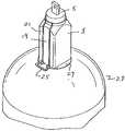
- FIG. 1is a view of the protective sleeve of the present invention installed in protective position over a gas valve of a gas bottle.
- FIG. 2Ais a cross-sectional view of the protective sleeve of FIG. 1 .
- FIG. 2Bis a cross-sectional view of another embodiment of the protective sleeve of FIG. 1 .
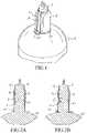
- FIG. 3is a view of one embodiment of the protective sleeve of the present invention.
- FIG. 4is a view of another embodiment of the protective sleeve of the present invention.
- the present inventioncomprises a protective sleeve 1 for use in connection with valve stems for gas bottles 29 .
- the protective sleeve 1is comprised of an elongated body 3 of such length as to extend along at least a portion of the length of the valve stem 5 .
- the protective sleeveincludes a locking mechanism to inhibit or prevent removal of the protective sleeve from the valve stem when placed thereover.
- the locking mechanismmay, for example, comprise a ratchet-type projection 7 , 7 ′ extending outwardly from an interior surface 9 of the protective sleeve which is adapted to physically engage with an orifice 11 in an opposing surface 13 of the valve stem. When so engaged, the protective sleeve is prevented from being removed from the valve stem upon being placed thereover due to engagement of said projection 7 , 7 ′ with the orifice 11 .
- the outwardly extending projectionmay be of any suitable cross-sectional configuration. However, while the cross-sectional configuration of the outwardly extending projection is not critical, the cross-sectional configuration is configured to fit snugly within the orifice in the valve stem. Multiple outwardly extending projections may be provided to the extent that additional locking with a corresponding orifice is provided and/or believed necessary.
- the protective sleeveis preferably open-ended at each end. As shown in FIGS. 3 and 4 , the sleeve has an open end 15 which is adjacent the gas bottle, and an open end 17 through which the end of the valve stem extends upon installation of the protective sleeve on the valve stem. See also FIG. 2A and 2B which depict the valve stem extending through the protective sleeve, with one open end of the protective sleeve adjacent the gas bottle, and an opposing open end having a valve stem extending therethrough.
- the outwardly extending projection 7is shown in FIG. 2A as having a shoulder at one end thereof and ramp at the other end thereof.
- the shoulderserves to lock against an interior surface of an orifice, while the ramp serves to facilitate placing the sleeve in locking engagement with the valve stem.
- each end of the projection 7 ′may include a shoulder to lock against adjacent sides of the orifice.
- the dimension of the projectionis preferably sized to fit snugly within the orifice.
- the outwardly extending projectionis positioned along inner surface 9 at a position which enables the projection to cooperatively engage an orifice in the valve stem.
- the projectionwill be substantially centrally-disposed as shown in FIGS. 3 and 4 (shown in phantom).
- the base of the projectionmay be of any suitable cross-sectional configuration, such as circular, square, rectangular, etc., as long as the projection is capable of cooperatively engaging the opposing orifice and such that a surface of the projection may lock (or abut) against an adjacent surface of the orifice to inhibit the sleeve from being removed from engagement with the valve stem.
- the protective sleevealso includes a tear strip 19 positioned along a side 21 of the protective sleeve. A portion of the protective sleeve may thus be removed by tearing so as to permit disengagement and removal of the protective sleeve from the valve stem.
- the tear stripextends longitudinally along at least a portion of a side 21 of the protective sleeve, and is defined laterally by parallel tear lines 23 , 23 ′ formed in a side of the protective sleeve.
- the tear linespreferably extend along the entire longitudinal extent of the protective sleeve as shown in FIG. 3 , but are not required to do so as shown in FIG. 4 .
- the tear linesneed only extend along a portion of a side of the protective sleeve to an extent sufficient to permit disengagement of the sleeve from the valve stem.
- the tear stripmay be formed on any of the sides of the protective sleeve, although as depicted, in a preferred embodiment, the tear strip is formed on a side of the protective sleeve opposite the side on which the locking mechanism is formed. However, the tear strip may be formed on any side of the protective sleeve, including the side which includes the locking mechanism (as long as the formation of the tear lines does not interfere with the formation of the locking mechanism during the molding process). Multiple tear strips may be employed as deemed suitable in multiple sides of the protective sleeve.
- a grip member 25is preferably provided which is attached to a portion of the tear strip to facilitate tearing of the tear strip.
- the configuration of the grip memberis not critical, and different configurations may be used as shown in FIGS. 3 and 4 .
- the protective sleevemay further include support flange members extending laterally outwardly from the bottom of said protective sleeve.
- the flange members 27assist in providing support for the base of the protective sleeve on top of the gas bottle 29 upon engagement with the valve stem if the gas bottle has an upper surface which may provide suitable support for such flanges.
- the protective sleeveis preferably comprised of a plastic resin material, and once formed, is sufficiently flexible to be placed over the valve stem and into engagement therewith, and sufficiently inflexible to remain engaged therewith absent removal of the tear strip.
- the protective sleevemay be comprised of a variety of plastic resin materials, such as low density polyethylene or filled flexible polyvinyl chloride. The selection of such materials and the molding method by which the sleeve may be formed are well known to those of ordinary skill in the art.
Landscapes
- Engineering & Computer Science (AREA)
- Mechanical Engineering (AREA)
- General Engineering & Computer Science (AREA)
- Filling Or Discharging Of Gas Storage Vessels (AREA)
- Containers And Packaging Bodies Having A Special Means To Remove Contents (AREA)
Abstract
Description
Claims (7)
Priority Applications (5)
| Application Number | Priority Date | Filing Date | Title |
|---|---|---|---|
| US11/522,542US7681587B2 (en) | 2006-09-15 | 2006-09-15 | Gas bottle valve stem protective sleeve |
| US11/996,729US8141578B2 (en) | 2006-09-15 | 2007-09-14 | Gas bottle valve stem protective sleeve |
| PCT/US2007/078502WO2008034065A2 (en) | 2006-09-15 | 2007-09-14 | Gas bottle valve stem protective sleeve |
| US12/929,373US8464749B2 (en) | 2006-09-15 | 2011-01-19 | Gas bottle valve body protective device |
| US13/370,817US20120192967A1 (en) | 2006-09-15 | 2012-02-10 | Gas bottle valve stem protective device |
Applications Claiming Priority (1)
| Application Number | Priority Date | Filing Date | Title |
|---|---|---|---|
| US11/522,542US7681587B2 (en) | 2006-09-15 | 2006-09-15 | Gas bottle valve stem protective sleeve |
Related Child Applications (3)
| Application Number | Title | Priority Date | Filing Date |
|---|---|---|---|
| US11/996,729Continuation-In-PartUS8141578B2 (en) | 2006-09-15 | 2007-09-14 | Gas bottle valve stem protective sleeve |
| PCT/US2007/078502Continuation-In-PartWO2008034065A2 (en) | 2006-09-15 | 2007-09-14 | Gas bottle valve stem protective sleeve |
| US99672908AContinuation-In-Part | 2006-09-15 | 2008-01-24 |
Publications (2)
| Publication Number | Publication Date |
|---|---|
| US20080066809A1 US20080066809A1 (en) | 2008-03-20 |
| US7681587B2true US7681587B2 (en) | 2010-03-23 |
Family
ID=39145221
Family Applications (3)
| Application Number | Title | Priority Date | Filing Date |
|---|---|---|---|
| US11/522,542Active2028-02-20US7681587B2 (en) | 2006-09-15 | 2006-09-15 | Gas bottle valve stem protective sleeve |
| US11/996,729Active2029-05-13US8141578B2 (en) | 2006-09-15 | 2007-09-14 | Gas bottle valve stem protective sleeve |
| US13/370,817AbandonedUS20120192967A1 (en) | 2006-09-15 | 2012-02-10 | Gas bottle valve stem protective device |
Family Applications After (2)
| Application Number | Title | Priority Date | Filing Date |
|---|---|---|---|
| US11/996,729Active2029-05-13US8141578B2 (en) | 2006-09-15 | 2007-09-14 | Gas bottle valve stem protective sleeve |
| US13/370,817AbandonedUS20120192967A1 (en) | 2006-09-15 | 2012-02-10 | Gas bottle valve stem protective device |
Country Status (2)
| Country | Link |
|---|---|
| US (3) | US7681587B2 (en) |
| WO (1) | WO2008034065A2 (en) |
Cited By (3)
| Publication number | Priority date | Publication date | Assignee | Title |
|---|---|---|---|---|
| US20100126596A1 (en)* | 2006-09-15 | 2010-05-27 | Protective Industries, Inc. | Gas bottle valve stem protective sleeve |
| US20110210134A1 (en)* | 2006-09-15 | 2011-09-01 | Zeyfang Rederick W | Gas bottle valve stem protective sleeve |
| USD917669S1 (en)* | 2019-10-10 | 2021-04-27 | Sodastream Industries Ltd. | Valve |
Families Citing this family (7)
| Publication number | Priority date | Publication date | Assignee | Title |
|---|---|---|---|---|
| US20130220447A1 (en)* | 2012-02-24 | 2013-08-29 | Rederick W. Zeyfang | Gas bottle valve stem protective device with optional finger grips |
| FR2991432B1 (en)* | 2012-06-04 | 2015-02-06 | Air Liquide | CAP FOR FLUID CONNECTION, FAUCET, BOTTLE AND FILLING METHOD THEREOF |
| US20140196800A1 (en)* | 2013-01-11 | 2014-07-17 | Progressive Plastics, Inc | Post valve protective device |
| GB2514362A (en)* | 2013-05-20 | 2014-11-26 | Linde Ag | Tamper evidence |
| FR3011612B1 (en)* | 2013-10-07 | 2015-10-30 | Rovip | PROTECTIVE CAP FOR GAS BOTTLE |
| US10145484B2 (en) | 2014-03-06 | 2018-12-04 | Hyperkinetics Corporation | Valve cover |
| FR3052232B1 (en)* | 2016-06-07 | 2018-11-16 | Air Liquide Sante Int | THERMO-RETRACTABLE SLEEVE FOR BLOC GAS CONTAINER TAP |
Citations (22)
| Publication number | Priority date | Publication date | Assignee | Title |
|---|---|---|---|---|
| US3102658A (en) | 1961-06-27 | 1963-09-03 | Super Whip Valve Co | Tamper-proof caps or closures for containers |
| US3125242A (en) | 1964-03-17 | x j jsj | ||
| US3587654A (en) | 1968-11-12 | 1971-06-28 | Superior Valve | Quick-removable seal caps for fittings and the like |
| US3684124A (en) | 1970-09-10 | 1972-08-15 | John S Song | Tamper-proof overcap for can |
| US4095713A (en) | 1977-07-08 | 1978-06-20 | The Coca-Cola Company | Tamper resistant cap for quick-disconnect coupling plug |
| US4616763A (en) | 1985-12-03 | 1986-10-14 | Replicap Products, Inc. | Tamper-evident disposable cap for container valve plug |
| US4630638A (en) | 1986-01-28 | 1986-12-23 | Acorn Engineering Company | Rotating cap, screen and mounting means for protecting air metering valve |
| US4664288A (en) | 1986-04-28 | 1987-05-12 | Clairol Incorporated | Pressure venting closure cap for a container spout |
| US4712705A (en) | 1987-01-30 | 1987-12-15 | Stoffel Seals Corporation | Tamper indicating cap seal for container valves |
| US4729488A (en) | 1986-08-14 | 1988-03-08 | Bankers Trust Co. | Tamper-evident cover for threaded neck |
| US5144972A (en) | 1991-10-02 | 1992-09-08 | Dryden Gale E | Stopcock with a protective assembly |
| US5191992A (en) | 1991-05-24 | 1993-03-09 | Safe T Seal Limited | Tamperproof sealing arrangement for gas cylinders |
| US5397012A (en) | 1993-09-01 | 1995-03-14 | Payge International Inc. | Tamper-proof sealing plug assembly |
| US5544770A (en)* | 1993-05-07 | 1996-08-13 | Travisano; Frank P. | Tamper evident seal and system |
| WO1997029969A1 (en) | 1996-02-15 | 1997-08-21 | International Plastics And Equipment Corporation | Snap-on tamper evident closure |
| US6003714A (en) | 1998-08-11 | 1999-12-21 | Buermann; Henry | Compressed gas cylinder safety cap and valve seal retainer |
| US6286702B1 (en)* | 1999-11-16 | 2001-09-11 | Henry Buermann | Pressure release safety cap |
| US6378170B1 (en) | 1999-03-29 | 2002-04-30 | Canimex, Inc. | Security seal for collars used to tension spring in garage door assemblies |
| USD468002S1 (en) | 2002-04-30 | 2002-12-31 | Alliance Plastics | Protective valve cap |
| FR2828678A1 (en) | 2001-07-31 | 2003-02-21 | Repsol Butano Sa | Protection cap for pressurized gas bottle valve comprises body containing valve having rupture sections and tear off band in lower section |
| US20030127138A1 (en) | 2002-01-08 | 2003-07-10 | Marconi S.R.L. | Security device |
| US20030201266A1 (en) | 2002-04-30 | 2003-10-30 | Alliance Plastics | Protective valve cap |
Family Cites Families (5)
| Publication number | Priority date | Publication date | Assignee | Title |
|---|---|---|---|---|
| IES950381A2 (en) | 1995-05-25 | 1995-12-27 | Rustsun Limited | A tamper evident seal |
| USD466002S1 (en)* | 2001-09-26 | 2002-11-26 | Softpac Industries, Inc. | Flexible pouch |
| US7681587B2 (en)* | 2006-09-15 | 2010-03-23 | Protective Industries, Inc. | Gas bottle valve stem protective sleeve |
| USD612012S1 (en) | 2007-05-07 | 2010-03-16 | Henry Buermann | Seal retainer strap having flanges |
| USD612013S1 (en) | 2007-10-02 | 2010-03-16 | Henry Buermann | Seal retainer and cover |
- 2006
- 2006-09-15USUS11/522,542patent/US7681587B2/enactiveActive
- 2007
- 2007-09-14USUS11/996,729patent/US8141578B2/enactiveActive
- 2007-09-14WOPCT/US2007/078502patent/WO2008034065A2/enactiveApplication Filing
- 2012
- 2012-02-10USUS13/370,817patent/US20120192967A1/ennot_activeAbandoned
Patent Citations (23)
| Publication number | Priority date | Publication date | Assignee | Title |
|---|---|---|---|---|
| US3125242A (en) | 1964-03-17 | x j jsj | ||
| US3102658A (en) | 1961-06-27 | 1963-09-03 | Super Whip Valve Co | Tamper-proof caps or closures for containers |
| US3587654A (en) | 1968-11-12 | 1971-06-28 | Superior Valve | Quick-removable seal caps for fittings and the like |
| US3684124A (en) | 1970-09-10 | 1972-08-15 | John S Song | Tamper-proof overcap for can |
| US4095713A (en) | 1977-07-08 | 1978-06-20 | The Coca-Cola Company | Tamper resistant cap for quick-disconnect coupling plug |
| US4616763A (en) | 1985-12-03 | 1986-10-14 | Replicap Products, Inc. | Tamper-evident disposable cap for container valve plug |
| US4630638A (en) | 1986-01-28 | 1986-12-23 | Acorn Engineering Company | Rotating cap, screen and mounting means for protecting air metering valve |
| US4664288A (en) | 1986-04-28 | 1987-05-12 | Clairol Incorporated | Pressure venting closure cap for a container spout |
| US4729488A (en) | 1986-08-14 | 1988-03-08 | Bankers Trust Co. | Tamper-evident cover for threaded neck |
| US4712705A (en) | 1987-01-30 | 1987-12-15 | Stoffel Seals Corporation | Tamper indicating cap seal for container valves |
| US5191992A (en) | 1991-05-24 | 1993-03-09 | Safe T Seal Limited | Tamperproof sealing arrangement for gas cylinders |
| US5144972A (en) | 1991-10-02 | 1992-09-08 | Dryden Gale E | Stopcock with a protective assembly |
| US5544770A (en)* | 1993-05-07 | 1996-08-13 | Travisano; Frank P. | Tamper evident seal and system |
| US5397012A (en) | 1993-09-01 | 1995-03-14 | Payge International Inc. | Tamper-proof sealing plug assembly |
| WO1997029969A1 (en) | 1996-02-15 | 1997-08-21 | International Plastics And Equipment Corporation | Snap-on tamper evident closure |
| US6003714A (en) | 1998-08-11 | 1999-12-21 | Buermann; Henry | Compressed gas cylinder safety cap and valve seal retainer |
| US6378170B1 (en) | 1999-03-29 | 2002-04-30 | Canimex, Inc. | Security seal for collars used to tension spring in garage door assemblies |
| US6286702B1 (en)* | 1999-11-16 | 2001-09-11 | Henry Buermann | Pressure release safety cap |
| FR2828678A1 (en) | 2001-07-31 | 2003-02-21 | Repsol Butano Sa | Protection cap for pressurized gas bottle valve comprises body containing valve having rupture sections and tear off band in lower section |
| US20030127138A1 (en) | 2002-01-08 | 2003-07-10 | Marconi S.R.L. | Security device |
| USD468002S1 (en) | 2002-04-30 | 2002-12-31 | Alliance Plastics | Protective valve cap |
| US20030201266A1 (en) | 2002-04-30 | 2003-10-30 | Alliance Plastics | Protective valve cap |
| US6854616B2 (en) | 2002-04-30 | 2005-02-15 | Alliance Plastics | Protective valve cap |
Non-Patent Citations (1)
| Title |
|---|
| Gas Cylinder Valve Protective Sleeve marketed by Alliance Plastics year 2000 to 2005 (estimated). |
Cited By (5)
| Publication number | Priority date | Publication date | Assignee | Title |
|---|---|---|---|---|
| US20100126596A1 (en)* | 2006-09-15 | 2010-05-27 | Protective Industries, Inc. | Gas bottle valve stem protective sleeve |
| US20110210134A1 (en)* | 2006-09-15 | 2011-09-01 | Zeyfang Rederick W | Gas bottle valve stem protective sleeve |
| US8141578B2 (en)* | 2006-09-15 | 2012-03-27 | Protective Industries, Inc. | Gas bottle valve stem protective sleeve |
| US8464749B2 (en) | 2006-09-15 | 2013-06-18 | Protective Industries, Inc. | Gas bottle valve body protective device |
| USD917669S1 (en)* | 2019-10-10 | 2021-04-27 | Sodastream Industries Ltd. | Valve |
Also Published As
| Publication number | Publication date |
|---|---|
| US20120192967A1 (en) | 2012-08-02 |
| US8141578B2 (en) | 2012-03-27 |
| US20080066809A1 (en) | 2008-03-20 |
| US20100126596A1 (en) | 2010-05-27 |
| WO2008034065A2 (en) | 2008-03-20 |
| WO2008034065A3 (en) | 2008-05-08 |
Similar Documents
| Publication | Publication Date | Title |
|---|---|---|
| US7681587B2 (en) | Gas bottle valve stem protective sleeve | |
| US10252851B2 (en) | Evacuated bottle system | |
| US11230421B2 (en) | Evacuated bottle system | |
| US8205645B2 (en) | Sealing apparatus | |
| US5915418A (en) | Closure for pipes and the like | |
| US2817372A (en) | Transfusion assembly | |
| US20050016873A1 (en) | Desiccant vial assembly for effervescent tablets | |
| TW200930634A (en) | Method and apparatus for dispensing fluids | |
| AU2014228432A1 (en) | Vacuum bottle stopper for wine, inert gas supply, and method | |
| US20160136048A1 (en) | Evacuated bottle system | |
| US6575333B1 (en) | Child resistant spout closure | |
| NO20065692L (en) | Screw caps. | |
| US20080110784A1 (en) | Carrier for containerized fluids | |
| EP1422161A3 (en) | Transport and storage container for liquids | |
| CN112135579A (en) | Protective container for sterile medical implants | |
| KR20210080758A (en) | protection cap for pipe | |
| US20060278653A1 (en) | Center pull tab plug with sealing flange | |
| WO2009044133A1 (en) | Apparatus and method for preserving wine | |
| WO2007139377A1 (en) | Container for waste to be thermally treated | |
| US8464749B2 (en) | Gas bottle valve body protective device | |
| US7806151B2 (en) | Drum cap venting device | |
| US7156254B2 (en) | Blow molded drum | |
| EP0176608A1 (en) | Drinking straw | |
| US11136230B2 (en) | Apparatus for opening safety locked bottle caps | |
| JP2008516855A (en) | Container, lid and clip for it |
Legal Events
| Date | Code | Title | Description |
|---|---|---|---|
| AS | Assignment | Owner name:PROTECTIVE INDUSTRIES, LLC, NEW YORK Free format text:ASSIGNMENT OF ASSIGNORS INTEREST;ASSIGNOR:ZEYFANG, FREDERICK W.;REEL/FRAME:018591/0367 Effective date:20061114 Owner name:PROTECTIVE INDUSTRIES, LLC,NEW YORK Free format text:ASSIGNMENT OF ASSIGNORS INTEREST;ASSIGNOR:ZEYFANG, FREDERICK W.;REEL/FRAME:018591/0367 Effective date:20061114 | |
| STCF | Information on status: patent grant | Free format text:PATENTED CASE | |
| RR | Request for reexamination filed | Effective date:20100709 | |
| AS | Assignment | Owner name:PROTECTIVE INDUSTRIES, INC., NEW YORK Free format text:ASSIGNMENT OF ASSIGNORS INTEREST;ASSIGNOR:ZEYFANG, FREDERICK W.;REEL/FRAME:025238/0217 Effective date:20101027 | |
| AS | Assignment | Owner name:GENERAL ELECTRIC CAPITAL CORPORATION, AS ADMINISTR Free format text:SECURITY AGREEMENT;ASSIGNOR:PROTECTIVE INDUSTRIES, INC.;REEL/FRAME:026325/0543 Effective date:20110523 | |
| FPAY | Fee payment | Year of fee payment:4 | |
| AS | Assignment | Owner name:GENERAL ELECTRIC CAPITAL CORPORATION, AS ADMINISTR Free format text:SECURITY AGREEMENT;ASSIGNOR:PROTECTIVE INDUSTRIES, INC.;REEL/FRAME:031360/0632 Effective date:20131007 Owner name:PROTECTIVE INDUSTRIES, INC., NEW YORK Free format text:RELEASE BY SECURED PARTY;ASSIGNOR:GENERAL ELECTRIC CAPITAL CORPORATION, AS ADMINISTRATIVE AGENT;REEL/FRAME:031357/0538 Effective date:20131007 | |
| FPB1 | Reexamination decision cancelled all claims | ||
| AS | Assignment | Owner name:PROTECTIVE INDUSTRIES, INC., NEW YORK Free format text:CORRECTIVE ASSIGNMENT TO CORRECT THE APPLICATION NO. PREVIOUSLY RECORDED AT REEL: 031357 FRAME: 0538. ASSIGNOR(S) HEREBY CONFIRMS THE RELEASE BY SECURED PARTY;ASSIGNOR:GENERAL ELECTRIC CAPITAL CORPORATION, AS ADMINISTRATIVE AGENT;REEL/FRAME:032971/0323 Effective date:20131007 | |
| AS | Assignment | Owner name:PROTECTIVE INDUSTRIES, INC., NEW YORK Free format text:PATENT RELEASE AND REASSIGNMENT;ASSIGNOR:GENERAL ELECTRIC CAPITAL CORPORATION;REEL/FRAME:035198/0601 Effective date:20150312 | |
| FEPP | Fee payment procedure | Free format text:MAINTENANCE FEE REMINDER MAILED (ORIGINAL EVENT CODE: REM.) | |
| FEPP | Fee payment procedure | Free format text:7.5 YR SURCHARGE - LATE PMT W/IN 6 MO, LARGE ENTITY (ORIGINAL EVENT CODE: M1555) | |
| MAFP | Maintenance fee payment | Free format text:PAYMENT OF MAINTENANCE FEE, 8TH YEAR, LARGE ENTITY (ORIGINAL EVENT CODE: M1552) Year of fee payment:8 | |
| MAFP | Maintenance fee payment | Free format text:PAYMENT OF MAINTENANCE FEE, 12TH YEAR, LARGE ENTITY (ORIGINAL EVENT CODE: M1553); ENTITY STATUS OF PATENT OWNER: LARGE ENTITY Year of fee payment:12 |