US7680528B2 - Method for the graphical representation of a medical instrument inserted at least partially into an object under examination - Google Patents
Method for the graphical representation of a medical instrument inserted at least partially into an object under examinationDownload PDFInfo
- Publication number
- US7680528B2 US7680528B2US11/522,261US52226106AUS7680528B2US 7680528 B2US7680528 B2US 7680528B2US 52226106 AUS52226106 AUS 52226106AUS 7680528 B2US7680528 B2US 7680528B2
- Authority
- US
- United States
- Prior art keywords
- image
- medical instrument
- instrument
- object under
- generated
- Prior art date
- Legal status (The legal status is an assumption and is not a legal conclusion. Google has not performed a legal analysis and makes no representation as to the accuracy of the status listed.)
- Active, expires
Links
Images


Classifications
- A—HUMAN NECESSITIES
- A61—MEDICAL OR VETERINARY SCIENCE; HYGIENE
- A61B—DIAGNOSIS; SURGERY; IDENTIFICATION
- A61B90/00—Instruments, implements or accessories specially adapted for surgery or diagnosis and not covered by any of the groups A61B1/00 - A61B50/00, e.g. for luxation treatment or for protecting wound edges
- A61B90/36—Image-producing devices or illumination devices not otherwise provided for
- A—HUMAN NECESSITIES
- A61—MEDICAL OR VETERINARY SCIENCE; HYGIENE
- A61B—DIAGNOSIS; SURGERY; IDENTIFICATION
- A61B6/00—Apparatus or devices for radiation diagnosis; Apparatus or devices for radiation diagnosis combined with radiation therapy equipment
- A61B6/12—Arrangements for detecting or locating foreign bodies
- G—PHYSICS
- G06—COMPUTING OR CALCULATING; COUNTING
- G06T—IMAGE DATA PROCESSING OR GENERATION, IN GENERAL
- G06T7/00—Image analysis
- G06T7/70—Determining position or orientation of objects or cameras
- A—HUMAN NECESSITIES
- A61—MEDICAL OR VETERINARY SCIENCE; HYGIENE
- A61B—DIAGNOSIS; SURGERY; IDENTIFICATION
- A61B90/00—Instruments, implements or accessories specially adapted for surgery or diagnosis and not covered by any of the groups A61B1/00 - A61B50/00, e.g. for luxation treatment or for protecting wound edges
- A61B90/36—Image-producing devices or illumination devices not otherwise provided for
- A61B2090/364—Correlation of different images or relation of image positions in respect to the body
- A—HUMAN NECESSITIES
- A61—MEDICAL OR VETERINARY SCIENCE; HYGIENE
- A61B—DIAGNOSIS; SURGERY; IDENTIFICATION
- A61B6/00—Apparatus or devices for radiation diagnosis; Apparatus or devices for radiation diagnosis combined with radiation therapy equipment
- A61B6/44—Constructional features of apparatus for radiation diagnosis
- A61B6/4429—Constructional features of apparatus for radiation diagnosis related to the mounting of source units and detector units
- A61B6/4435—Constructional features of apparatus for radiation diagnosis related to the mounting of source units and detector units the source unit and the detector unit being coupled by a rigid structure
- A61B6/4441—Constructional features of apparatus for radiation diagnosis related to the mounting of source units and detector units the source unit and the detector unit being coupled by a rigid structure the rigid structure being a C-arm or U-arm
- A—HUMAN NECESSITIES
- A61—MEDICAL OR VETERINARY SCIENCE; HYGIENE
- A61B—DIAGNOSIS; SURGERY; IDENTIFICATION
- A61B6/00—Apparatus or devices for radiation diagnosis; Apparatus or devices for radiation diagnosis combined with radiation therapy equipment
- A61B6/54—Control of apparatus or devices for radiation diagnosis
- A61B6/541—Control of apparatus or devices for radiation diagnosis involving acquisition triggered by a physiological signal
- G—PHYSICS
- G06—COMPUTING OR CALCULATING; COUNTING
- G06T—IMAGE DATA PROCESSING OR GENERATION, IN GENERAL
- G06T2207/00—Indexing scheme for image analysis or image enhancement
- G06T2207/10—Image acquisition modality
- G06T2207/10072—Tomographic images
- G—PHYSICS
- G06—COMPUTING OR CALCULATING; COUNTING
- G06T—IMAGE DATA PROCESSING OR GENERATION, IN GENERAL
- G06T2207/00—Indexing scheme for image analysis or image enhancement
- G06T2207/30—Subject of image; Context of image processing
- G06T2207/30004—Biomedical image processing
- G—PHYSICS
- G06—COMPUTING OR CALCULATING; COUNTING
- G06T—IMAGE DATA PROCESSING OR GENERATION, IN GENERAL
- G06T2207/00—Indexing scheme for image analysis or image enhancement
- G06T2207/30—Subject of image; Context of image processing
- G06T2207/30004—Biomedical image processing
- G06T2207/30021—Catheter; Guide wire
Definitions
- the status of the object under examinationis generally controlled in a manner that is appropriate for the intervention risk.
- Body functions of the object under examinationare recorded for this purpose.
- the position and/or optionally the location of the medical instrument within the object under examinationis of interest as well as patient status.
- Examples of medical instrumentsare catheters, guide wires, stents, sheaths, biopsy needles or other means that are inserted at least partially into the object under examination during medical interventions.
- a methodis required, which allows the locating—in other words determination of the position and/or location—of the medical instrument. Medical personnel also have to determine any changes in the position and/or location of the medical instrument on a continuous basis, in order to control the insertion into or further progress of the medical instrument in the object under examination. Such a method can increase the accuracy of the intervention, reduce damage to the object under examination and improve patient safety.
- a method for determining the position of a medical instrumentis known from the published patent application DE 100 04 764 A1.
- the first method stepcomprises the pre-operative acquisition of computed tomograms, which make it possible to generate a three-dimensional image data record before the actual medical intervention on the object under examination.
- Thisis followed by an intra-operative method step, wherein two-dimensional images are acquired using an x-ray device during the intervention on the object under examination and used to determine the position of the medical instrument.
- a position measuring deviceis also provided for the extra-corporal determination of the position of the medical instrument.
- the position of the medical instrument within the three-dimensional image data recordis also calculated by data assignment of the image data generated pre-operatively and intra-operatively. Disadvantages of this method result for example from the cost of additional pre-operative x-ray examinations and the existing installation of a position measuring device.
- the end of the vectordefines a new interpolation point.
- the characteristics of the polylinesuch as color, line thickness, flashing display, etc., can be tailored to the respective conditions of the intervention.
- this methodreduces subsequent image processing outlay and therefore computing time.
- medical personnelcan work more accurately due to the improved quality. This is of particularly high importance when working with filigree structures in sensitive systems, such as a neurological guide wire in a vascular system in the brain.
- the instrument imageis vectorized electronically. This means that no user interaction is required to capture the medical instrument.
- the medical instrumentis identified automatically from the instrument image and captured by a polyline. This reduces the burden on medical personnel and allows a faster representation due to the reduced quantity of data.
- the change between instrument imagesis captured by an enlarged image section around the end of the polyline. It is then not necessary to search through the whole image for changes, just a relevant search region, which can be found at the visible ends of the inserted medical instrument. By subtracting these image regions from temporally successive instrument images it is possible to determine the change in the position and location of the polyline. Restricting the search region reduces the outlay required to capture the change and thus the information to be processed to monitor the site and location of the medical instrument in the form of the polyline.
- the temporal sequence of the images of the medical instrument in the object under examinationis backed up electronically.
- the intervention carried outcan thus be monitored subsequently in a virtual manner at a computer, which improves the safety and understanding of the patient with regard to the intervention and can be used for learning processes within the medical team or in medical training.
- the reference imageis determined as the image of the object under examination in the absence of the medical instrument.
- a reference imageis also known as a mask image. It shows the examination region of interest in the object under examination without the medical instrument. This also reduces the time, for which the medical instrument is inserted into the object under examination.
- the reference imageis determined as an image capturing the medical instrument without the use of contrast agents. While the reference image is being acquired the medical instrument is already present in the object under examination. Such a procedure is advantageous, if the examination region of interest in the object under examination changes. The reference image background therefore also changes.
- the polylineis determined with the object under examination as a two-dimensional projection. This allows two-dimensional location with little outlay.
- the vectorized representation of the medical instrument as a polylineallows it to be clearly differentiated from its environment, in that polyline parameters—such as color, line thickness, etc.—can be tailored and it can therefore be easily identified.
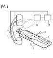
- the triggering system for the acquisition of images 5 and 6is of less importance, as rhythmic or arrhythmic movement does not generally occur in the head region of a patient 2 .
- the acquired images 5 and 6are further processed according to the inventive method and the location and position of the guide wire 3 in the object under examination 2 is determined in an image processing unit 12 .
- the resultis displayed on an image output unit 13 and thus made available to the medical personnel.
- This imagecan be superimposed with the already generated images 4 , to display the change in the polyline 8 and 8 ′ on the image output unit 13 .
- the change in the polyline formationcan for example be highlighted separately in the spatial representation, perhaps by a flashing display of the changes in the polyline formation in the object under examination 2 .
Landscapes
- Health & Medical Sciences (AREA)
- Life Sciences & Earth Sciences (AREA)
- Engineering & Computer Science (AREA)
- Medical Informatics (AREA)
- Surgery (AREA)
- General Health & Medical Sciences (AREA)
- Veterinary Medicine (AREA)
- Biomedical Technology (AREA)
- Heart & Thoracic Surgery (AREA)
- Physics & Mathematics (AREA)
- Molecular Biology (AREA)
- Animal Behavior & Ethology (AREA)
- Nuclear Medicine, Radiotherapy & Molecular Imaging (AREA)
- Public Health (AREA)
- Pathology (AREA)
- Oral & Maxillofacial Surgery (AREA)
- Biophysics (AREA)
- High Energy & Nuclear Physics (AREA)
- Optics & Photonics (AREA)
- Radiology & Medical Imaging (AREA)
- Computer Vision & Pattern Recognition (AREA)
- General Physics & Mathematics (AREA)
- Theoretical Computer Science (AREA)
- Apparatus For Radiation Diagnosis (AREA)
Abstract
Description
Claims (14)
Applications Claiming Priority (3)
| Application Number | Priority Date | Filing Date | Title |
|---|---|---|---|
| DE102005044405.9 | 2005-09-16 | ||
| DE102005044405ADE102005044405A1 (en) | 2005-09-16 | 2005-09-16 | Method of producing an image of a medical instrument at least partly inserted into an object or patient under examination using vectors |
| DE102005044405 | 2005-09-16 |
Publications (2)
| Publication Number | Publication Date |
|---|---|
| US20070083102A1 US20070083102A1 (en) | 2007-04-12 |
| US7680528B2true US7680528B2 (en) | 2010-03-16 |
Family
ID=37775793
Family Applications (1)
| Application Number | Title | Priority Date | Filing Date |
|---|---|---|---|
| US11/522,261Active2027-06-20US7680528B2 (en) | 2005-09-16 | 2006-09-15 | Method for the graphical representation of a medical instrument inserted at least partially into an object under examination |
Country Status (3)
| Country | Link |
|---|---|
| US (1) | US7680528B2 (en) |
| CN (1) | CN101023886A (en) |
| DE (1) | DE102005044405A1 (en) |
Cited By (25)
| Publication number | Priority date | Publication date | Assignee | Title |
|---|---|---|---|---|
| US20080208040A1 (en)* | 2007-02-26 | 2008-08-28 | Siemens Aktiengesellschaft | Method for three-dimensional localization of an instrument for an interventional access and associated device |
| US20080262297A1 (en)* | 2004-04-26 | 2008-10-23 | Super Dimension Ltd. | System and Method for Image-Based Alignment of an Endoscope |
| US20100160733A1 (en)* | 2002-04-17 | 2010-06-24 | Pinhas Gilboa | Endoscope Structures And Techniques For Navigating To A Target In Branched Structure |
| US20100198015A1 (en)* | 2003-09-15 | 2010-08-05 | Benny Greenburg | System Of Accessories For Use With Bronchoscopes |
| US8452068B2 (en) | 2008-06-06 | 2013-05-28 | Covidien Lp | Hybrid registration method |
| US8473032B2 (en) | 2008-06-03 | 2013-06-25 | Superdimension, Ltd. | Feature-based registration method |
| US8611984B2 (en) | 2009-04-08 | 2013-12-17 | Covidien Lp | Locatable catheter |
| US8764725B2 (en) | 2004-02-09 | 2014-07-01 | Covidien Lp | Directional anchoring mechanism, method and applications thereof |
| US8905920B2 (en) | 2007-09-27 | 2014-12-09 | Covidien Lp | Bronchoscope adapter and method |
| US8932207B2 (en) | 2008-07-10 | 2015-01-13 | Covidien Lp | Integrated multi-functional endoscopic tool |
| US9575140B2 (en) | 2008-04-03 | 2017-02-21 | Covidien Lp | Magnetic interference detection system and method |
| US10418705B2 (en) | 2016-10-28 | 2019-09-17 | Covidien Lp | Electromagnetic navigation antenna assembly and electromagnetic navigation system including the same |
| US10426555B2 (en) | 2015-06-03 | 2019-10-01 | Covidien Lp | Medical instrument with sensor for use in a system and method for electromagnetic navigation |
| US10446931B2 (en) | 2016-10-28 | 2019-10-15 | Covidien Lp | Electromagnetic navigation antenna assembly and electromagnetic navigation system including the same |
| US10478254B2 (en) | 2016-05-16 | 2019-11-19 | Covidien Lp | System and method to access lung tissue |
| US10517505B2 (en) | 2016-10-28 | 2019-12-31 | Covidien Lp | Systems, methods, and computer-readable media for optimizing an electromagnetic navigation system |
| US10582834B2 (en) | 2010-06-15 | 2020-03-10 | Covidien Lp | Locatable expandable working channel and method |
| US10615500B2 (en) | 2016-10-28 | 2020-04-07 | Covidien Lp | System and method for designing electromagnetic navigation antenna assemblies |
| US10638952B2 (en) | 2016-10-28 | 2020-05-05 | Covidien Lp | Methods, systems, and computer-readable media for calibrating an electromagnetic navigation system |
| US10722311B2 (en) | 2016-10-28 | 2020-07-28 | Covidien Lp | System and method for identifying a location and/or an orientation of an electromagnetic sensor based on a map |
| US10751126B2 (en) | 2016-10-28 | 2020-08-25 | Covidien Lp | System and method for generating a map for electromagnetic navigation |
| US10792106B2 (en) | 2016-10-28 | 2020-10-06 | Covidien Lp | System for calibrating an electromagnetic navigation system |
| US10952593B2 (en) | 2014-06-10 | 2021-03-23 | Covidien Lp | Bronchoscope adapter |
| US11219489B2 (en) | 2017-10-31 | 2022-01-11 | Covidien Lp | Devices and systems for providing sensors in parallel with medical tools |
| US20220051401A1 (en)* | 2020-08-12 | 2022-02-17 | Siemens Healthcare Gmbh | Providing a scene with synthetic contrast |
Families Citing this family (6)
| Publication number | Priority date | Publication date | Assignee | Title |
|---|---|---|---|---|
| US20080317195A1 (en)* | 2007-06-20 | 2008-12-25 | Kabushiki Kaisha Toshiba | Medical-diagnosis assisting apparatus, medical-diagnosis assisting method, and radiodiagnosis apparatus |
| US8566738B2 (en)* | 2007-11-19 | 2013-10-22 | Koninklijke Philips N.V. | System for collecting data elements relating to events of interventional procedure |
| US9592100B2 (en)* | 2007-12-31 | 2017-03-14 | St. Jude Medical, Atrial Fibrillation Division, Inc. | Method and apparatus for encoding catheters with markers for identifying with imaging systems |
| US8423182B2 (en)* | 2009-03-09 | 2013-04-16 | Intuitive Surgical Operations, Inc. | Adaptable integrated energy control system for electrosurgical tools in robotic surgical systems |
| CN104640514B (en) | 2012-09-17 | 2019-05-07 | 直观外科手术操作公司 | Method and system for assigning input devices to teleoperated surgical instrument functionality |
| US10631939B2 (en) | 2012-11-02 | 2020-04-28 | Intuitive Surgical Operations, Inc. | Systems and methods for mapping flux supply paths |
Citations (17)
| Publication number | Priority date | Publication date | Assignee | Title |
|---|---|---|---|---|
| US4637929A (en)* | 1985-01-04 | 1987-01-20 | Salutar, Inc. | Ferrioxamine-paramagnetic contrast agents for MR imaging, composition, apparatus and use |
| US4638798A (en)* | 1980-09-10 | 1987-01-27 | Shelden C Hunter | Stereotactic method and apparatus for locating and treating or removing lesions |
| US4827413A (en) | 1987-06-16 | 1989-05-02 | Kabushiki Kaisha Toshiba | Modified back-to-front three dimensional reconstruction algorithm |
| US5274551A (en) | 1991-11-29 | 1993-12-28 | General Electric Company | Method and apparatus for real-time navigation assist in interventional radiological procedures |
| US5937144A (en)* | 1997-05-06 | 1999-08-10 | Adobe Systems Incorporated | Rasterized proxy of a vector image |
| US6219522B1 (en)* | 1998-09-17 | 2001-04-17 | Canon Kabushiki Kaisha | Fuser and image forming apparatus |
| US6259802B1 (en)* | 1997-06-30 | 2001-07-10 | Siemens Corporate Research, Inc. | Object tracking technique using polyline contours |
| DE10004764A1 (en) | 2000-02-03 | 2001-08-09 | Philips Corp Intellectual Pty | Method for determining the position of a medical instrument |
| EP0633548B1 (en) | 1993-06-29 | 2002-01-30 | Koninklijke Philips Electronics N.V. | Method and device for determining a contour in a space having a density distribution |
| US6640127B1 (en)* | 1999-06-10 | 2003-10-28 | Olympus Optical Co., Ltd. | Surgical operation navigating system using a reference frame |
| US20030216634A1 (en)* | 2002-05-15 | 2003-11-20 | Van Muiswinkel Arianne M.C. | Sweeping real-time single point fiber |
| US20040077952A1 (en)* | 2002-10-21 | 2004-04-22 | Rafter Patrick G. | System and method for improved diagnostic image displays |
| WO2004044847A1 (en) | 2002-11-13 | 2004-05-27 | Koninklijke Philips Electronics N.V. | Medical viewing system and method for detecting boundary structures |
| US20040171924A1 (en)* | 2003-01-30 | 2004-09-02 | Mire David A. | Method and apparatus for preplanning a surgical procedure |
| US20050089143A1 (en) | 2003-09-19 | 2005-04-28 | Kabushiki Kaisha Toshiba | X-ray diagnosis apparatus and method for creating image data |
| US20050165292A1 (en) | 2002-04-04 | 2005-07-28 | Simon David A. | Method and apparatus for virtual digital subtraction angiography |
| US7148907B2 (en)* | 1999-07-26 | 2006-12-12 | Microsoft Corporation | Mixed but indistinguishable raster and vector image data types |
- 2005
- 2005-09-16DEDE102005044405Apatent/DE102005044405A1/ennot_activeWithdrawn
- 2006
- 2006-09-15USUS11/522,261patent/US7680528B2/enactiveActive
- 2006-09-18CNCNA2006101309535Apatent/CN101023886A/enactivePending
Patent Citations (18)
| Publication number | Priority date | Publication date | Assignee | Title |
|---|---|---|---|---|
| US4638798A (en)* | 1980-09-10 | 1987-01-27 | Shelden C Hunter | Stereotactic method and apparatus for locating and treating or removing lesions |
| US4637929A (en)* | 1985-01-04 | 1987-01-20 | Salutar, Inc. | Ferrioxamine-paramagnetic contrast agents for MR imaging, composition, apparatus and use |
| US4827413A (en) | 1987-06-16 | 1989-05-02 | Kabushiki Kaisha Toshiba | Modified back-to-front three dimensional reconstruction algorithm |
| US5274551A (en) | 1991-11-29 | 1993-12-28 | General Electric Company | Method and apparatus for real-time navigation assist in interventional radiological procedures |
| EP0633548B1 (en) | 1993-06-29 | 2002-01-30 | Koninklijke Philips Electronics N.V. | Method and device for determining a contour in a space having a density distribution |
| US5937144A (en)* | 1997-05-06 | 1999-08-10 | Adobe Systems Incorporated | Rasterized proxy of a vector image |
| US6259802B1 (en)* | 1997-06-30 | 2001-07-10 | Siemens Corporate Research, Inc. | Object tracking technique using polyline contours |
| US6219522B1 (en)* | 1998-09-17 | 2001-04-17 | Canon Kabushiki Kaisha | Fuser and image forming apparatus |
| US6640127B1 (en)* | 1999-06-10 | 2003-10-28 | Olympus Optical Co., Ltd. | Surgical operation navigating system using a reference frame |
| US7148907B2 (en)* | 1999-07-26 | 2006-12-12 | Microsoft Corporation | Mixed but indistinguishable raster and vector image data types |
| DE10004764A1 (en) | 2000-02-03 | 2001-08-09 | Philips Corp Intellectual Pty | Method for determining the position of a medical instrument |
| US6542770B2 (en) | 2000-02-03 | 2003-04-01 | Koninklijke Philips Electronics N.V. | Method of determining the position of a medical instrument |
| US20050165292A1 (en) | 2002-04-04 | 2005-07-28 | Simon David A. | Method and apparatus for virtual digital subtraction angiography |
| US20030216634A1 (en)* | 2002-05-15 | 2003-11-20 | Van Muiswinkel Arianne M.C. | Sweeping real-time single point fiber |
| US20040077952A1 (en)* | 2002-10-21 | 2004-04-22 | Rafter Patrick G. | System and method for improved diagnostic image displays |
| WO2004044847A1 (en) | 2002-11-13 | 2004-05-27 | Koninklijke Philips Electronics N.V. | Medical viewing system and method for detecting boundary structures |
| US20040171924A1 (en)* | 2003-01-30 | 2004-09-02 | Mire David A. | Method and apparatus for preplanning a surgical procedure |
| US20050089143A1 (en) | 2003-09-19 | 2005-04-28 | Kabushiki Kaisha Toshiba | X-ray diagnosis apparatus and method for creating image data |
Non-Patent Citations (1)
| Title |
|---|
| Sven Behnke, Marcus Pfister and Raul Rojas, "Recognition of Handwritten Digits using Structural Information", Proceedings of International Conference on Neural Networks, ICNN '97, vol. 3, 1997, pp. 1391-1396. |
Cited By (63)
| Publication number | Priority date | Publication date | Assignee | Title |
|---|---|---|---|---|
| US20100160733A1 (en)* | 2002-04-17 | 2010-06-24 | Pinhas Gilboa | Endoscope Structures And Techniques For Navigating To A Target In Branched Structure |
| US8696548B2 (en) | 2002-04-17 | 2014-04-15 | Covidien Lp | Endoscope structures and techniques for navigating to a target in branched structure |
| US10743748B2 (en) | 2002-04-17 | 2020-08-18 | Covidien Lp | Endoscope structures and techniques for navigating to a target in branched structure |
| US8696685B2 (en) | 2002-04-17 | 2014-04-15 | Covidien Lp | Endoscope structures and techniques for navigating to a target in branched structure |
| US9642514B2 (en) | 2002-04-17 | 2017-05-09 | Covidien Lp | Endoscope structures and techniques for navigating to a target in a branched structure |
| US8663088B2 (en) | 2003-09-15 | 2014-03-04 | Covidien Lp | System of accessories for use with bronchoscopes |
| US9089261B2 (en) | 2003-09-15 | 2015-07-28 | Covidien Lp | System of accessories for use with bronchoscopes |
| US20100198015A1 (en)* | 2003-09-15 | 2010-08-05 | Benny Greenburg | System Of Accessories For Use With Bronchoscopes |
| US10383509B2 (en) | 2003-09-15 | 2019-08-20 | Covidien Lp | System of accessories for use with bronchoscopes |
| US8764725B2 (en) | 2004-02-09 | 2014-07-01 | Covidien Lp | Directional anchoring mechanism, method and applications thereof |
| US7998062B2 (en) | 2004-03-29 | 2011-08-16 | Superdimension, Ltd. | Endoscope structures and techniques for navigating to a target in branched structure |
| US10321803B2 (en) | 2004-04-26 | 2019-06-18 | Covidien Lp | System and method for image-based alignment of an endoscope |
| US9055881B2 (en) | 2004-04-26 | 2015-06-16 | Super Dimension Ltd. | System and method for image-based alignment of an endoscope |
| US20080262297A1 (en)* | 2004-04-26 | 2008-10-23 | Super Dimension Ltd. | System and Method for Image-Based Alignment of an Endoscope |
| US8099153B2 (en)* | 2007-02-26 | 2012-01-17 | Siemens Aktiengesellschaft | Method for three-dimensional localization of an instrument for an interventional access and associated device |
| US20080208040A1 (en)* | 2007-02-26 | 2008-08-28 | Siemens Aktiengesellschaft | Method for three-dimensional localization of an instrument for an interventional access and associated device |
| US8905920B2 (en) | 2007-09-27 | 2014-12-09 | Covidien Lp | Bronchoscope adapter and method |
| US9668639B2 (en) | 2007-09-27 | 2017-06-06 | Covidien Lp | Bronchoscope adapter and method |
| US10980400B2 (en) | 2007-09-27 | 2021-04-20 | Covidien Lp | Bronchoscope adapter and method |
| US10390686B2 (en) | 2007-09-27 | 2019-08-27 | Covidien Lp | Bronchoscope adapter and method |
| US9986895B2 (en) | 2007-09-27 | 2018-06-05 | Covidien Lp | Bronchoscope adapter and method |
| US9575140B2 (en) | 2008-04-03 | 2017-02-21 | Covidien Lp | Magnetic interference detection system and method |
| US11783498B2 (en) | 2008-06-03 | 2023-10-10 | Covidien Lp | Feature-based registration method |
| US11074702B2 (en) | 2008-06-03 | 2021-07-27 | Covidien Lp | Feature-based registration method |
| US9659374B2 (en) | 2008-06-03 | 2017-05-23 | Covidien Lp | Feature-based registration method |
| US9117258B2 (en) | 2008-06-03 | 2015-08-25 | Covidien Lp | Feature-based registration method |
| US8473032B2 (en) | 2008-06-03 | 2013-06-25 | Superdimension, Ltd. | Feature-based registration method |
| US10096126B2 (en) | 2008-06-03 | 2018-10-09 | Covidien Lp | Feature-based registration method |
| US10285623B2 (en) | 2008-06-06 | 2019-05-14 | Covidien Lp | Hybrid registration method |
| US8467589B2 (en) | 2008-06-06 | 2013-06-18 | Covidien Lp | Hybrid registration method |
| US9271803B2 (en) | 2008-06-06 | 2016-03-01 | Covidien Lp | Hybrid registration method |
| US10674936B2 (en) | 2008-06-06 | 2020-06-09 | Covidien Lp | Hybrid registration method |
| US10478092B2 (en) | 2008-06-06 | 2019-11-19 | Covidien Lp | Hybrid registration method |
| US11931141B2 (en) | 2008-06-06 | 2024-03-19 | Covidien Lp | Hybrid registration method |
| US8452068B2 (en) | 2008-06-06 | 2013-05-28 | Covidien Lp | Hybrid registration method |
| US8932207B2 (en) | 2008-07-10 | 2015-01-13 | Covidien Lp | Integrated multi-functional endoscopic tool |
| US10070801B2 (en) | 2008-07-10 | 2018-09-11 | Covidien Lp | Integrated multi-functional endoscopic tool |
| US11241164B2 (en) | 2008-07-10 | 2022-02-08 | Covidien Lp | Integrated multi-functional endoscopic tool |
| US11234611B2 (en) | 2008-07-10 | 2022-02-01 | Covidien Lp | Integrated multi-functional endoscopic tool |
| US10912487B2 (en) | 2008-07-10 | 2021-02-09 | Covidien Lp | Integrated multi-function endoscopic tool |
| US10154798B2 (en) | 2009-04-08 | 2018-12-18 | Covidien Lp | Locatable catheter |
| US9113813B2 (en) | 2009-04-08 | 2015-08-25 | Covidien Lp | Locatable catheter |
| US8611984B2 (en) | 2009-04-08 | 2013-12-17 | Covidien Lp | Locatable catheter |
| US10582834B2 (en) | 2010-06-15 | 2020-03-10 | Covidien Lp | Locatable expandable working channel and method |
| US10952593B2 (en) | 2014-06-10 | 2021-03-23 | Covidien Lp | Bronchoscope adapter |
| US10426555B2 (en) | 2015-06-03 | 2019-10-01 | Covidien Lp | Medical instrument with sensor for use in a system and method for electromagnetic navigation |
| US10478254B2 (en) | 2016-05-16 | 2019-11-19 | Covidien Lp | System and method to access lung tissue |
| US11786317B2 (en) | 2016-05-16 | 2023-10-17 | Covidien Lp | System and method to access lung tissue |
| US11160617B2 (en) | 2016-05-16 | 2021-11-02 | Covidien Lp | System and method to access lung tissue |
| US10792106B2 (en) | 2016-10-28 | 2020-10-06 | Covidien Lp | System for calibrating an electromagnetic navigation system |
| US11672604B2 (en) | 2016-10-28 | 2023-06-13 | Covidien Lp | System and method for generating a map for electromagnetic navigation |
| US10517505B2 (en) | 2016-10-28 | 2019-12-31 | Covidien Lp | Systems, methods, and computer-readable media for optimizing an electromagnetic navigation system |
| US10615500B2 (en) | 2016-10-28 | 2020-04-07 | Covidien Lp | System and method for designing electromagnetic navigation antenna assemblies |
| US10638952B2 (en) | 2016-10-28 | 2020-05-05 | Covidien Lp | Methods, systems, and computer-readable media for calibrating an electromagnetic navigation system |
| US10418705B2 (en) | 2016-10-28 | 2019-09-17 | Covidien Lp | Electromagnetic navigation antenna assembly and electromagnetic navigation system including the same |
| US11786314B2 (en) | 2016-10-28 | 2023-10-17 | Covidien Lp | System for calibrating an electromagnetic navigation system |
| US10446931B2 (en) | 2016-10-28 | 2019-10-15 | Covidien Lp | Electromagnetic navigation antenna assembly and electromagnetic navigation system including the same |
| US11759264B2 (en) | 2016-10-28 | 2023-09-19 | Covidien Lp | System and method for identifying a location and/or an orientation of an electromagnetic sensor based on a map |
| US10751126B2 (en) | 2016-10-28 | 2020-08-25 | Covidien Lp | System and method for generating a map for electromagnetic navigation |
| US10722311B2 (en) | 2016-10-28 | 2020-07-28 | Covidien Lp | System and method for identifying a location and/or an orientation of an electromagnetic sensor based on a map |
| US11219489B2 (en) | 2017-10-31 | 2022-01-11 | Covidien Lp | Devices and systems for providing sensors in parallel with medical tools |
| US20220051401A1 (en)* | 2020-08-12 | 2022-02-17 | Siemens Healthcare Gmbh | Providing a scene with synthetic contrast |
| US12288324B2 (en)* | 2020-08-12 | 2025-04-29 | Siemens Healthineers Ag | Providing a scene with synthetic contrast |
Also Published As
| Publication number | Publication date |
|---|---|
| US20070083102A1 (en) | 2007-04-12 |
| DE102005044405A1 (en) | 2007-03-22 |
| CN101023886A (en) | 2007-08-29 |
Similar Documents
| Publication | Publication Date | Title |
|---|---|---|
| US7680528B2 (en) | Method for the graphical representation of a medical instrument inserted at least partially into an object under examination | |
| JP7093801B2 (en) | A system that facilitates position adjustment and guidance during surgery | |
| JP6581598B2 (en) | Device for determining a specific position of a catheter | |
| US8942457B2 (en) | Navigating an interventional device | |
| JP4564840B2 (en) | Percutaneous catheter guide method | |
| CN107847274B (en) | Method and apparatus for providing updated patient images during robotic surgery | |
| JP2009532162A (en) | Determining the tissue surrounding an object inserted in a patient | |
| AU2015238800B2 (en) | Real-time simulation of fluoroscopic images | |
| CN111403017A (en) | Medical assistance device, system, and method for determining a deformation of an object | |
| US20100261999A1 (en) | System and method to determine the position of a medical instrument | |
| US20210137607A1 (en) | Measuring a length of movement of an elongate intraluminal | |
| CN115317005A (en) | Method and system for providing corrected data sets | |
| EP3703011A1 (en) | Interventional device tracking | |
| NL1023485C2 (en) | Device and method for navigation of an instrument. | |
| CN113597289B (en) | Assists in moving inserted components within an object |
Legal Events
| Date | Code | Title | Description |
|---|---|---|---|
| AS | Assignment | Owner name:SIEMENS AKTIENGESELLSCHAFT,GERMANY Free format text:ASSIGNMENT OF ASSIGNORS INTEREST;ASSIGNORS:PFISTER, MARCUS;SANDKAMP, BERNHARD;SIGNING DATES FROM 20060821 TO 20060912;REEL/FRAME:018495/0638 Owner name:SIEMENS AKTIENGESELLSCHAFT, GERMANY Free format text:ASSIGNMENT OF ASSIGNORS INTEREST;ASSIGNORS:PFISTER, MARCUS;SANDKAMP, BERNHARD;REEL/FRAME:018495/0638;SIGNING DATES FROM 20060821 TO 20060912 | |
| STCF | Information on status: patent grant | Free format text:PATENTED CASE | |
| FPAY | Fee payment | Year of fee payment:4 | |
| AS | Assignment | Owner name:SIEMENS HEALTHCARE GMBH, GERMANY Free format text:ASSIGNMENT OF ASSIGNORS INTEREST;ASSIGNOR:SIEMENS AKTIENGESELLSCHAFT;REEL/FRAME:039271/0561 Effective date:20160610 | |
| FPAY | Fee payment | Year of fee payment:8 | |
| MAFP | Maintenance fee payment | Free format text:PAYMENT OF MAINTENANCE FEE, 12TH YEAR, LARGE ENTITY (ORIGINAL EVENT CODE: M1553); ENTITY STATUS OF PATENT OWNER: LARGE ENTITY Year of fee payment:12 | |
| AS | Assignment | Owner name:SIEMENS HEALTHINEERS AG, GERMANY Free format text:ASSIGNMENT OF ASSIGNORS INTEREST;ASSIGNOR:SIEMENS HEALTHCARE GMBH;REEL/FRAME:066088/0256 Effective date:20231219 | |
| AS | Assignment | Owner name:SIEMENS HEALTHINEERS AG, GERMANY Free format text:CORRECTIVE ASSIGNMENT TO CORRECT THE ASSIGNEE PREVIOUSLY RECORDED AT REEL: 066088 FRAME: 0256. ASSIGNOR(S) HEREBY CONFIRMS THE ASSIGNMENT;ASSIGNOR:SIEMENS HEALTHCARE GMBH;REEL/FRAME:071178/0246 Effective date:20231219 |