US7680247B2 - Combined image processing computer for medical diagnostics in the fields of radiography and fluoroscopy - Google Patents
Combined image processing computer for medical diagnostics in the fields of radiography and fluoroscopyDownload PDFInfo
- Publication number
- US7680247B2 US7680247B2US11/860,924US86092407AUS7680247B2US 7680247 B2US7680247 B2US 7680247B2US 86092407 AUS86092407 AUS 86092407AUS 7680247 B2US7680247 B2US 7680247B2
- Authority
- US
- United States
- Prior art keywords
- radiation
- radiography
- fluoroscopy
- signal
- processing
- Prior art date
- Legal status (The legal status is an assumption and is not a legal conclusion. Google has not performed a legal analysis and makes no representation as to the accuracy of the status listed.)
- Active
Links
Images


Classifications
- A—HUMAN NECESSITIES
- A61—MEDICAL OR VETERINARY SCIENCE; HYGIENE
- A61B—DIAGNOSIS; SURGERY; IDENTIFICATION
- A61B6/00—Apparatus or devices for radiation diagnosis; Apparatus or devices for radiation diagnosis combined with radiation therapy equipment
- A61B6/06—Diaphragms
- A—HUMAN NECESSITIES
- A61—MEDICAL OR VETERINARY SCIENCE; HYGIENE
- A61B—DIAGNOSIS; SURGERY; IDENTIFICATION
- A61B6/00—Apparatus or devices for radiation diagnosis; Apparatus or devices for radiation diagnosis combined with radiation therapy equipment
- A61B6/48—Diagnostic techniques
- A61B6/486—Diagnostic techniques involving generating temporal series of image data
- A61B6/487—Diagnostic techniques involving generating temporal series of image data involving fluoroscopy
- A—HUMAN NECESSITIES
- A61—MEDICAL OR VETERINARY SCIENCE; HYGIENE
- A61B—DIAGNOSIS; SURGERY; IDENTIFICATION
- A61B6/00—Apparatus or devices for radiation diagnosis; Apparatus or devices for radiation diagnosis combined with radiation therapy equipment
- A61B6/52—Devices using data or image processing specially adapted for radiation diagnosis
- A61B6/5211—Devices using data or image processing specially adapted for radiation diagnosis involving processing of medical diagnostic data
- G—PHYSICS
- G16—INFORMATION AND COMMUNICATION TECHNOLOGY [ICT] SPECIALLY ADAPTED FOR SPECIFIC APPLICATION FIELDS
- G16H—HEALTHCARE INFORMATICS, i.e. INFORMATION AND COMMUNICATION TECHNOLOGY [ICT] SPECIALLY ADAPTED FOR THE HANDLING OR PROCESSING OF MEDICAL OR HEALTHCARE DATA
- G16H50/00—ICT specially adapted for medical diagnosis, medical simulation or medical data mining; ICT specially adapted for detecting, monitoring or modelling epidemics or pandemics
- G16H50/20—ICT specially adapted for medical diagnosis, medical simulation or medical data mining; ICT specially adapted for detecting, monitoring or modelling epidemics or pandemics for computer-aided diagnosis, e.g. based on medical expert systems
- A—HUMAN NECESSITIES
- A61—MEDICAL OR VETERINARY SCIENCE; HYGIENE
- A61B—DIAGNOSIS; SURGERY; IDENTIFICATION
- A61B6/00—Apparatus or devices for radiation diagnosis; Apparatus or devices for radiation diagnosis combined with radiation therapy equipment
- A61B6/44—Constructional features of apparatus for radiation diagnosis
- A61B6/4429—Constructional features of apparatus for radiation diagnosis related to the mounting of source units and detector units
- A61B6/4464—Constructional features of apparatus for radiation diagnosis related to the mounting of source units and detector units the source unit or the detector unit being mounted to ceiling
- G—PHYSICS
- G16—INFORMATION AND COMMUNICATION TECHNOLOGY [ICT] SPECIALLY ADAPTED FOR SPECIFIC APPLICATION FIELDS
- G16H—HEALTHCARE INFORMATICS, i.e. INFORMATION AND COMMUNICATION TECHNOLOGY [ICT] SPECIALLY ADAPTED FOR THE HANDLING OR PROCESSING OF MEDICAL OR HEALTHCARE DATA
- G16H30/00—ICT specially adapted for the handling or processing of medical images
- G16H30/40—ICT specially adapted for the handling or processing of medical images for processing medical images, e.g. editing
Definitions
- the present inventionrelates generally to medical imaging and, in particular, to a method and apparatus for combining a radiography system and a fluoroscopy system into a combined medical diagnostic system.
- the two imaging systemsare characterized by different properties with respect to the frequency and resolution of the generated medical images.
- radiography images of unmoving subjectsare generated with an optimally high resolution
- fluoroscopyimages of moving subjects are predominantly generated that have a lower resolution than the images in radiography.
- radiographyproduces high resolution still images whereas fluoroscopy produces lower resolution moving images.
- the known prior artprovides that different systems are used for the image processing in the different systems for fluoroscopy and radiography.
- the computers which are usedare optimized for the respective requirement of the imaging system.
- the most important characteristic data for the image computers of the various systemsare listed in the following
- Image sizeapproximately 3000 2 (approximately 5-10 megapixels per image)
- Image frequencyapproximately 2 images per minute (with a maximum of 10 images per minute)
- Duration of the image calculationa maximum of a few seconds
- Acceleration voltage of the x-ray tubeapproximately 40-150 kV
- Image processing algorithmslinear and non-linear, multiscalar frequency filters
- Image sizeapproximately 1000 2 (approximately 1 megapixel per image)
- Image frequencyapproximately 0.5 images per second up to a maximum of 30 images per second
- Acceleration voltage of the x-ray tubeapproximately 40-90 kV
- the two different computersalso exhibit differences in the operation since the workflows in the image generation are different between fluoroscopy and radiography.
- the different operating workflows between the two acquisition methodsare thereby depicted in different operating interfaces on the computer monitors.
- an image chainmust be provided for each different detector that can calculate images with the different resolution and frequency. These images are generated either by different radiation receivers for the different applications or may be generated by a combined radiation receiver for both image types.
- the present inventionprovides an apparatus and method for combining the previously different image processing computers for image generation in fluoroscopy and radiography medical applications into one system with which it is possible to perform fluoroscopy and radiography imaging in a single system for medical diagnostics.
- the present method and apparatusprovides a combined radiography and fluoroscopy system in which the image data from the respective different sensors is processed on a single image processing computer.
- An alternativeprovides a single radiation receiver capable of receiving and generating images from both radiography and fluoroscopy signals. This single receiver is connected to the single image processing computer.
- a further alternativeprovides different radiation receivers for the radiography and fluoroscopy devices and different computer systems connected to the different radiation receivers, the different computer systems being substantially identical as between the two systems.
- an image chain for both image typescan be achieved in that the individual elements of the image chain are designed such that both the different matrix sizes and the different image frequencies can be calculated. If some image chain components do not have the capability of being used for both image types, the corresponding parts must be separately realized for the respective requirements. These parts must then be connected in parallel with corresponding parts for the other image type in the sequence of the calculation steps, and the generated images are directed through the one or the other part of the image chain depending on the image requirements.
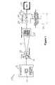
- FIG. 1is a schematic representation of a radiography system, also referred to as an x-ray system, for generating medical images;
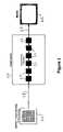
- FIG. 2is a schematic representation of an image system for image data processing of data from a radiography system
- FIG. 3is a schematic representation of an image system for image data processing of data from a fluoroscopy system
- FIG. 4is a schematic representation of a combined image system for image data processing of data from a radiography imaging device and of data from a fluoroscopy imaging device;
- FIG. 5is a schematic representation of combination of a fluoroscopy system and radiography system into a common system with separate image receivers and a common image computer for processing of both image types;
- FIG. 6is a schematic representation of combination of a fluoroscopy and radiography system in a common system with a common radiation receiver and a common image computer for processing of both image types;
- FIG. 7is a schematic representation of combination of a fluoroscopy and radiography system in a common system with separate image receivers and separate but substantially identical image computers for both image processing tasks.
- an imaging system 10 for medical imaging using x-raysincludes a high voltage generator 12 that generates the high voltages necessary to power the x-ray generating apparatus.
- the high voltage generator 12includes a control unit 14 by which the power is controlled. Power from the high voltage generator 12 is provided to an x-ray tube 16 where it is used to generate x-rays of a predetermined range of wavelengths.
- the x-ray energy from the x-ray tube 16is focused into a beam 18 and passes through a diaphragm 20 is used to set the depth of field for the image.
- the beam 18is directed toward an object to be imaged, which for a medical imaging system is a patient (not shown) so that portions of the beam are attenuated by the patient's tissues.
- the resulting patient imageis detected by a detector 22 positioned on the opposite side of the patient from the x-ray tube 16 .
- the detector 22 of the preferred embodimentis a digital image detector for x-rays of at least part of the range of wavelengths generated by the x-ray tube 16 .
- the detector 22also serves as a image intensifier to amplify faint image information.
- the radiation detector and image intensifier 22transmits an image signal to an image system 24 .
- the image system 24performs various image processing steps on the image data, as is known, to control contrast and exposure in the image, decrease noise in the image, and control object definition in the image, for example. Any known image processing steps may be applied. Image processing functions are performed by image processing units 26 in the image system 24 . More or fewer image processing units 26 may be provided as needed.
- the processed image datais preferably output at 28 as a generated image signal that may be transmitted to a storage system 30 .
- the storage system 30may be an external storage system using PACS (Picture Archiving and Communication System) technology to store the image on an external media, such as a DVD (Digital Versatile Disc).
- PACSPicture Archiving and Communication System
- the storage system 30may instead include a hard drive based storage, solid state storage, tape storage or other storage system.
- the generated imageis also provided to a monitor 32 so that the image data may be viewed by a medical professional, such as a doctor.
- the monitor 32may display the image immediately after processing or after the image has been stored.
- the radiography systemincludes a radiography detector 34 that senses the x-ray beam that has been directed through some portion of the patient and provides a detector signal 36 to an image system 38 .
- the detector 34has a predetermined resolution which for most radiography systems is a high resolution, and operates at a predetermined frequency range which is the frequency range used for radiography.
- the image system 38includes image processing units 40 that perform image processing steps on the detector signal 36 to produce a generated image signal 42 that is provided to a monitor 49 .
- the image processing units 40are specific to the radiography image signal 36 .
- FIG. 3shows a comparable portion of an imaging system for fluoroscopy.
- the systemincludes a detector and image intensifier 46 for receiving the fluoroscopic energy beam that has been directed through a portion of the patient.
- the fluoroscopic detector 46produces a detector signal 48 that is provided to an image system 50 .
- the fluoroscopic detector 46differs from the radiographic detector 34 in a number of ways, including the wavelength or frequency of the signal to be detected and the resolution of the detector.
- the image system 50 of the fluoroscopy systemhas image processing units 52 .
- the image processing units 52differ from those of the radiography system due to differences in the data and the processing needs of the system.
- the processing units 52produce a generated image signal 60 that is forwarded to a monitor 62 for viewing by a medical professional.
- a combined systemthat combines both radiography and fluoroscopy in one system.
- a detector 64is provided for detecting the radiography beam and transmitting a detected radiography signal 66 to an image system 68 .
- a detector and image intensifier 70 for a fluoroscope beamis also provided.
- the fluoroscope detector and image intensifier 70generates a detector signal 72 that is also provided to the same image system 68 as is used for the radiographic signal.
- the image system 68uses the same processing units 74 to process both the radiography signal 66 as well as the fluoroscopy signal 72 .
- These processes 74which are also referred to as modules, are capable of being performed on the both signals regardless of the differences in resolution and frequency.
- the processes which perform on both signal typesare referred to as common processes.
- the processing of the two signalsis significantly different and so separate processing units 76 and 78 are provided in parallel paths.
- the processing units 76perform fluoroscopy specific processes, while the processing units 78 perform radiography specific processes.
- the processes that are specific to the signalare referred to as path specific processes.
- the process 76is path specific to the fluoroscopy signal processing path and the process 78 is path specific to the radiography signal processing path.
- the respective detector specific process 76 or 78is completed and the resulting signal sent to a common processing unit 80 performs a further process on the image signal to generate the generated image signal 82 .
- the generated image signal 82is provided to a monitor 84 for display, although it may also be stored prior to or con with display, as noted above.
- detector specific processes and common processesmay differ from that shown so that detector specific processes may be provided at the beginning of the processing sequence, at the end, or at any point along the sequence.
- the signal processing sequencemay be split into detector specific process several times in the sequence, or only once. Changes in settings by the user may result in changes in which processes are used and whether the process requires a detector specific process or whether a common process can be used.
- the processes in the image processing sequencemay be performed by software, hardware, firmware or a combination thereof.
- the processesmay be performed by modules that are distinct from one another or by modules that are integrated with one or more other modules.
- the needs of various usersdiffer in terms of what they require of a medical image and so different modules or processes may be used depending on a user's needs.
- a radiography system 86typically includes a mount 88 that supports a radiation generator 90 including a depth diaphragm 92 to generate a beam 94 directed toward a patient (not shown), such as for a chest x-ray.
- the patientis positioned in the beam path and the beam is detected by a radiation receiver 96 .
- the beam generator 90 and radiation receiver 96are oriented in that example to image a standing patient for a chest x-ray, for example.
- the radiation receiver 96is mounted on a wall or wall unit 102 .
- the radiation receiver 96sends the signal to a computer 98 that performs radiography image processing radiation so that the generated image can be displayed on a monitor 100 .
- the medical personnelare not in the room during the radiographic imaging.
- a fluoroscopy system 104includes a radiation generator 106 with a depth of field diaphragm 108 .
- the radiation generator 106directs a beam to a table 110 where a patient who is to receive treatment, such inserting a cardiac stent or a pacemaker lead, for example, is lying.
- a radiation receiver 112is mounted below the table 110 .
- a light 114is positioned above the table 110 for better visibility of the patient by the medical personnel.
- the fluoroscopic imagesare typically made during an ongoing procedure on the patient and the medical personnel are in the room with the patient to perform the procedure.
- the image signal from the image receiver 112is forwarded to a computer 116 that is connected to a monitor 118 on which the image may be viewed. Since the fluoroscopic image is typically being viewed by the medical personnel during the medical procedure, it is important that the monitor 118 be positioned within easy view of the medical personnel performing the procedure.
- a combined system 120 for radiography and fluoroscopyincludes a mount 122 supporting a radiation generator 124 for radiographic signals.
- a depth diaphragm 126directs a beam 128 to a radiation receiver 130 that is mounted on a wall or wall unit 132 .
- the signalis sent from the receiver 130 to a computer 134 that includes a monitor 136 .
- the combined system 120also includes a radiation generator 138 that generates fluoroscopic signals which pass through a depth diaphragm 140 to form a beam 142 which is directed to a patient (not shown) on a table 144 .
- a fluoroscopic radiation detector 146is disposed in or beneath the table 144 to sense the fluoroscopic radiation.
- a beam shield 148is provided to shield medical personnel that are nearby from the energy of the beam 142 .
- Lighting 150is provided for illumination during the medical procedure.
- the fluoroscopic signal detected by the detector 146is transmitted to the same computer 134 for processing as the radiographic signals.
- the same monitor 136is used to view the results.
- the fluoroscopic image data and radiographic image datais processed according to FIG. 4 , for example, or the variations discussed in conjunction therewith.
- only one computer 134 and monitor 136need by provided and only one of each of the common modules in the image processing sequence. A savings of hardware and software results. Further, the common image processing system enables a user to learn only one system and still be able to perform processing on both types of signals.
- the combined system 160 of an alternative embodimentincludes a single radiation generator 162 or radiator that is powered to generate x-ray radiation.
- a controller in the radiation generator 162controls the energy output level and radiation frequency level to either generate radiographic radiation or fluoroscopic radiation.
- a depth diaphragm 164is provided to control the depth of field of the image. Since the combined system 160 will be used for both radiographic and fluoroscopic imaging, a beam shield 166 is provided to shield medical personnel from the beam. The shield 166 may be removable as needed, or not.
- a table 168 on which to place the patient during the procedureis provided, and a combined radiographic and fluoroscopic radiation receiver 170 is provided beneath the table 168 in a position opposite the generator 162 from the patients.
- a light fixture 172is provided in the room to improve the view by the medical personnel.
- the radiation receiver 170has a resolution sufficient for high resolution radiographic images but it may be switched to a lower resolution mode for the fluoroscopic imaging process.
- the read-out rate from the detector 170may also be switched to enable the rapid read-out required for real time fluoroscopic imaging.
- the detector 170 of a preferred embodimenthas a wide enough frequency range to detect either the radiographic or the fluoroscopic radiation, although it is also possible that the detector may be switched to operate at different frequencies.
- the radiation generator and detector of the combined systemmay be operable at the operating characteristics of the known radiographic and fluoroscopic systems or may operate outside of those parameters, such as at some frequency, energy level or resolution between the known parameters or beyond the known parameters.
- the detector signal from the detector 170is provided to a single computer 174 where processing is performed on the signal to provide a generated image signal.
- the processingpreferably is performed in accordance with FIG. 4 or one of the variations discussed in conjunction therewith.
- the resulting image signalis displayed on a monitor 176 and/or stored on a storage system.
- FIG. 7shows a further variation of the combined system.
- a radiographic system 180is provided, which has a radiation generator 182 , depth diaphragm 184 , and radiation detector 186 like that described previously.
- the detector signalis sent to a computer 188 for processing and display on a monitor 190 .
- the computer 188runs the combined process shown in FIG. 4 so that common processes are handled by common modules and a common interface appears on the monitor.
- a fluoroscopic system 198is also provided having a separate radiation generator 200 and separate radiation detector 202 .
- the signal from the fluoroscopic radiation detector 202is transmitted to a separate computer 204 for processing and display on a separate monitor 206 .
- the computer 204performs the combined process as shown in FIG. 4 or as discussed in conjunction therewith.
- the computers 188 of the radiographic system and 204 of the fluoroscopic systemare substantially identical in a preferred embodiment.
- the hardware portion, at least as to processing the signals,may be substantially identical or may be different as between the computers 188 and 204 . More importantly, the software that performs the image processing processes is substantially identical as between the two computers 188 and 204 .
- the same modulesare provided for the processing, the same user interface and same user commands are provided and the same output format is provided as between the two computers.
- both the generated images from the dedicated radiation receivers for fluoroscopy and radiography and images from a combined radiation receivercan be calculated with a universal image system.
- x-ray systemscan be realized with such an image system that can be used for both types of medical diagnostics; these systems can thus be used more universally than systems that support only one type of diagnostics.
- An expanded application range of a combined x-ray systemresults with simultaneously relatively slice cost increase relative to a dedicated system.
Landscapes
- Health & Medical Sciences (AREA)
- Life Sciences & Earth Sciences (AREA)
- Engineering & Computer Science (AREA)
- Medical Informatics (AREA)
- Public Health (AREA)
- Biomedical Technology (AREA)
- Pathology (AREA)
- General Health & Medical Sciences (AREA)
- Heart & Thoracic Surgery (AREA)
- Biophysics (AREA)
- Radiology & Medical Imaging (AREA)
- Nuclear Medicine, Radiotherapy & Molecular Imaging (AREA)
- Physics & Mathematics (AREA)
- Molecular Biology (AREA)
- Surgery (AREA)
- Animal Behavior & Ethology (AREA)
- High Energy & Nuclear Physics (AREA)
- Optics & Photonics (AREA)
- Veterinary Medicine (AREA)
- Computer Vision & Pattern Recognition (AREA)
- Data Mining & Analysis (AREA)
- Databases & Information Systems (AREA)
- Epidemiology (AREA)
- Primary Health Care (AREA)
- Apparatus For Radiation Diagnosis (AREA)
Abstract
Description
Claims (11)
Priority Applications (1)
| Application Number | Priority Date | Filing Date | Title |
|---|---|---|---|
| US11/860,924US7680247B2 (en) | 2007-09-25 | 2007-09-25 | Combined image processing computer for medical diagnostics in the fields of radiography and fluoroscopy |
Applications Claiming Priority (1)
| Application Number | Priority Date | Filing Date | Title |
|---|---|---|---|
| US11/860,924US7680247B2 (en) | 2007-09-25 | 2007-09-25 | Combined image processing computer for medical diagnostics in the fields of radiography and fluoroscopy |
Publications (2)
| Publication Number | Publication Date |
|---|---|
| US20090082971A1 US20090082971A1 (en) | 2009-03-26 |
| US7680247B2true US7680247B2 (en) | 2010-03-16 |
Family
ID=40472617
Family Applications (1)
| Application Number | Title | Priority Date | Filing Date |
|---|---|---|---|
| US11/860,924ActiveUS7680247B2 (en) | 2007-09-25 | 2007-09-25 | Combined image processing computer for medical diagnostics in the fields of radiography and fluoroscopy |
Country Status (1)
| Country | Link |
|---|---|
| US (1) | US7680247B2 (en) |
Cited By (48)
| Publication number | Priority date | Publication date | Assignee | Title |
|---|---|---|---|---|
| US20100008559A1 (en)* | 2008-07-14 | 2010-01-14 | Nunzio Alberto Borghese | Dynamic Error Correction in Radiographic Imaging |
| US9286673B2 (en) | 2012-10-05 | 2016-03-15 | Volcano Corporation | Systems for correcting distortions in a medical image and methods of use thereof |
| US9292918B2 (en) | 2012-10-05 | 2016-03-22 | Volcano Corporation | Methods and systems for transforming luminal images |
| US9301687B2 (en) | 2013-03-13 | 2016-04-05 | Volcano Corporation | System and method for OCT depth calibration |
| US9307926B2 (en) | 2012-10-05 | 2016-04-12 | Volcano Corporation | Automatic stent detection |
| US9324141B2 (en) | 2012-10-05 | 2016-04-26 | Volcano Corporation | Removal of A-scan streaking artifact |
| US9360630B2 (en) | 2011-08-31 | 2016-06-07 | Volcano Corporation | Optical-electrical rotary joint and methods of use |
| US9367965B2 (en) | 2012-10-05 | 2016-06-14 | Volcano Corporation | Systems and methods for generating images of tissue |
| US9383263B2 (en) | 2012-12-21 | 2016-07-05 | Volcano Corporation | Systems and methods for narrowing a wavelength emission of light |
| US9478940B2 (en) | 2012-10-05 | 2016-10-25 | Volcano Corporation | Systems and methods for amplifying light |
| US9486143B2 (en) | 2012-12-21 | 2016-11-08 | Volcano Corporation | Intravascular forward imaging device |
| US9596993B2 (en) | 2007-07-12 | 2017-03-21 | Volcano Corporation | Automatic calibration systems and methods of use |
| US9612105B2 (en) | 2012-12-21 | 2017-04-04 | Volcano Corporation | Polarization sensitive optical coherence tomography system |
| US9622706B2 (en) | 2007-07-12 | 2017-04-18 | Volcano Corporation | Catheter for in vivo imaging |
| US9709379B2 (en) | 2012-12-20 | 2017-07-18 | Volcano Corporation | Optical coherence tomography system that is reconfigurable between different imaging modes |
| US9730613B2 (en) | 2012-12-20 | 2017-08-15 | Volcano Corporation | Locating intravascular images |
| US9770172B2 (en) | 2013-03-07 | 2017-09-26 | Volcano Corporation | Multimodal segmentation in intravascular images |
| US9858668B2 (en) | 2012-10-05 | 2018-01-02 | Volcano Corporation | Guidewire artifact removal in images |
| US9867530B2 (en) | 2006-08-14 | 2018-01-16 | Volcano Corporation | Telescopic side port catheter device with imaging system and method for accessing side branch occlusions |
| US10058284B2 (en) | 2012-12-21 | 2018-08-28 | Volcano Corporation | Simultaneous imaging, monitoring, and therapy |
| US10070827B2 (en) | 2012-10-05 | 2018-09-11 | Volcano Corporation | Automatic image playback |
| US10166003B2 (en) | 2012-12-21 | 2019-01-01 | Volcano Corporation | Ultrasound imaging with variable line density |
| US10191220B2 (en) | 2012-12-21 | 2019-01-29 | Volcano Corporation | Power-efficient optical circuit |
| US10219887B2 (en) | 2013-03-14 | 2019-03-05 | Volcano Corporation | Filters with echogenic characteristics |
| US10219780B2 (en) | 2007-07-12 | 2019-03-05 | Volcano Corporation | OCT-IVUS catheter for concurrent luminal imaging |
| US10226597B2 (en) | 2013-03-07 | 2019-03-12 | Volcano Corporation | Guidewire with centering mechanism |
| US10238367B2 (en) | 2012-12-13 | 2019-03-26 | Volcano Corporation | Devices, systems, and methods for targeted cannulation |
| US10292677B2 (en) | 2013-03-14 | 2019-05-21 | Volcano Corporation | Endoluminal filter having enhanced echogenic properties |
| US10332228B2 (en) | 2012-12-21 | 2019-06-25 | Volcano Corporation | System and method for graphical processing of medical data |
| US10413317B2 (en) | 2012-12-21 | 2019-09-17 | Volcano Corporation | System and method for catheter steering and operation |
| US10420530B2 (en) | 2012-12-21 | 2019-09-24 | Volcano Corporation | System and method for multipath processing of image signals |
| US10426590B2 (en) | 2013-03-14 | 2019-10-01 | Volcano Corporation | Filters with echogenic characteristics |
| US10568586B2 (en) | 2012-10-05 | 2020-02-25 | Volcano Corporation | Systems for indicating parameters in an imaging data set and methods of use |
| US10595820B2 (en) | 2012-12-20 | 2020-03-24 | Philips Image Guided Therapy Corporation | Smooth transition catheters |
| US10638939B2 (en) | 2013-03-12 | 2020-05-05 | Philips Image Guided Therapy Corporation | Systems and methods for diagnosing coronary microvascular disease |
| US10724082B2 (en) | 2012-10-22 | 2020-07-28 | Bio-Rad Laboratories, Inc. | Methods for analyzing DNA |
| US10758207B2 (en) | 2013-03-13 | 2020-09-01 | Philips Image Guided Therapy Corporation | Systems and methods for producing an image from a rotational intravascular ultrasound device |
| US10939826B2 (en) | 2012-12-20 | 2021-03-09 | Philips Image Guided Therapy Corporation | Aspirating and removing biological material |
| US10942022B2 (en) | 2012-12-20 | 2021-03-09 | Philips Image Guided Therapy Corporation | Manual calibration of imaging system |
| US10993694B2 (en) | 2012-12-21 | 2021-05-04 | Philips Image Guided Therapy Corporation | Rotational ultrasound imaging catheter with extended catheter body telescope |
| US11026591B2 (en) | 2013-03-13 | 2021-06-08 | Philips Image Guided Therapy Corporation | Intravascular pressure sensor calibration |
| US11040140B2 (en) | 2010-12-31 | 2021-06-22 | Philips Image Guided Therapy Corporation | Deep vein thrombosis therapeutic methods |
| US11141063B2 (en) | 2010-12-23 | 2021-10-12 | Philips Image Guided Therapy Corporation | Integrated system architectures and methods of use |
| US11154313B2 (en) | 2013-03-12 | 2021-10-26 | The Volcano Corporation | Vibrating guidewire torquer and methods of use |
| US11272845B2 (en) | 2012-10-05 | 2022-03-15 | Philips Image Guided Therapy Corporation | System and method for instant and automatic border detection |
| US11406498B2 (en) | 2012-12-20 | 2022-08-09 | Philips Image Guided Therapy Corporation | Implant delivery system and implants |
| US12201477B2 (en) | 2012-10-05 | 2025-01-21 | Philips Image Guided Therapy Corporation | Methods and systems for establishing parameters for three-dimensional imaging |
| US12343198B2 (en) | 2013-03-14 | 2025-07-01 | Philips Image Guided Therapy Corporation | Delivery catheter having imaging capabilities |
Families Citing this family (2)
| Publication number | Priority date | Publication date | Assignee | Title |
|---|---|---|---|---|
| US9207334B1 (en)* | 2014-12-30 | 2015-12-08 | General Electric Company | Methods and systems for a light sensor in gamma ray detectors |
| CN113365557B (en)* | 2019-01-30 | 2024-05-14 | 富士胶片株式会社 | Medical image analysis device, method, and computer-readable storage medium |
Citations (12)
| Publication number | Priority date | Publication date | Assignee | Title |
|---|---|---|---|---|
| US1950531A (en)* | 1927-02-21 | 1934-03-13 | Gen Electric X Ray Corp | Circuit for X-ray multiple tube stands |
| US5022063A (en)* | 1989-01-25 | 1991-06-04 | Hitachi Medical Corporation | Multiple-mode scanning and beam current control x-ray TV apparatus |
| US5117447A (en)* | 1989-01-25 | 1992-05-26 | Hitachi Medical Corporation | Image input apparatus |
| US5636259A (en)* | 1995-05-18 | 1997-06-03 | Continental X-Ray Corporation | Universal radiographic/fluoroscopic digital room |
| US6095685A (en)* | 1997-01-17 | 2000-08-01 | Hitachi Medical Corporation | X-ray radioscopic apparatus |
| US6155713A (en)* | 1997-06-19 | 2000-12-05 | Kabushiki Kaisha Toshiba | X-ray diagnostic apparatus having an X-ray generating portion and an X-ray detecting portion independent of each other |
| US6205347B1 (en)* | 1998-02-27 | 2001-03-20 | Picker International, Inc. | Separate and combined multi-modality diagnostic imaging system |
| US6302579B1 (en)* | 1998-11-19 | 2001-10-16 | Siemens Aktiengesellschaft | Multiple examination arrangement with a number of imaging systems |
| US6318892B1 (en)* | 1998-10-28 | 2001-11-20 | Hitachi Medical Corporation | Radiography apparatus with rotatably supported cylindrical ring carrying image pickup unit |
| US6351518B2 (en)* | 1990-11-16 | 2002-02-26 | Hitachi Medical Corporation | Digital radiography system having an X-ray image intensifier tube |
| US6744912B2 (en)* | 1996-11-29 | 2004-06-01 | Varian Medical Systems Technologies, Inc. | Multiple mode digital X-ray imaging system |
| US7220052B2 (en)* | 2002-10-16 | 2007-05-22 | Kabushiki Kaisha Toshiba | X-ray diagnostic apparatus |
- 2007
- 2007-09-25USUS11/860,924patent/US7680247B2/enactiveActive
Patent Citations (12)
| Publication number | Priority date | Publication date | Assignee | Title |
|---|---|---|---|---|
| US1950531A (en)* | 1927-02-21 | 1934-03-13 | Gen Electric X Ray Corp | Circuit for X-ray multiple tube stands |
| US5022063A (en)* | 1989-01-25 | 1991-06-04 | Hitachi Medical Corporation | Multiple-mode scanning and beam current control x-ray TV apparatus |
| US5117447A (en)* | 1989-01-25 | 1992-05-26 | Hitachi Medical Corporation | Image input apparatus |
| US6351518B2 (en)* | 1990-11-16 | 2002-02-26 | Hitachi Medical Corporation | Digital radiography system having an X-ray image intensifier tube |
| US5636259A (en)* | 1995-05-18 | 1997-06-03 | Continental X-Ray Corporation | Universal radiographic/fluoroscopic digital room |
| US6744912B2 (en)* | 1996-11-29 | 2004-06-01 | Varian Medical Systems Technologies, Inc. | Multiple mode digital X-ray imaging system |
| US6095685A (en)* | 1997-01-17 | 2000-08-01 | Hitachi Medical Corporation | X-ray radioscopic apparatus |
| US6155713A (en)* | 1997-06-19 | 2000-12-05 | Kabushiki Kaisha Toshiba | X-ray diagnostic apparatus having an X-ray generating portion and an X-ray detecting portion independent of each other |
| US6205347B1 (en)* | 1998-02-27 | 2001-03-20 | Picker International, Inc. | Separate and combined multi-modality diagnostic imaging system |
| US6318892B1 (en)* | 1998-10-28 | 2001-11-20 | Hitachi Medical Corporation | Radiography apparatus with rotatably supported cylindrical ring carrying image pickup unit |
| US6302579B1 (en)* | 1998-11-19 | 2001-10-16 | Siemens Aktiengesellschaft | Multiple examination arrangement with a number of imaging systems |
| US7220052B2 (en)* | 2002-10-16 | 2007-05-22 | Kabushiki Kaisha Toshiba | X-ray diagnostic apparatus |
Cited By (58)
| Publication number | Priority date | Publication date | Assignee | Title |
|---|---|---|---|---|
| US9867530B2 (en) | 2006-08-14 | 2018-01-16 | Volcano Corporation | Telescopic side port catheter device with imaging system and method for accessing side branch occlusions |
| US9596993B2 (en) | 2007-07-12 | 2017-03-21 | Volcano Corporation | Automatic calibration systems and methods of use |
| US10219780B2 (en) | 2007-07-12 | 2019-03-05 | Volcano Corporation | OCT-IVUS catheter for concurrent luminal imaging |
| US11350906B2 (en) | 2007-07-12 | 2022-06-07 | Philips Image Guided Therapy Corporation | OCT-IVUS catheter for concurrent luminal imaging |
| US9622706B2 (en) | 2007-07-12 | 2017-04-18 | Volcano Corporation | Catheter for in vivo imaging |
| US8559691B2 (en)* | 2008-07-14 | 2013-10-15 | Cefla S.C. | Dynamic error correction in radiographic imaging |
| US20100008559A1 (en)* | 2008-07-14 | 2010-01-14 | Nunzio Alberto Borghese | Dynamic Error Correction in Radiographic Imaging |
| US11141063B2 (en) | 2010-12-23 | 2021-10-12 | Philips Image Guided Therapy Corporation | Integrated system architectures and methods of use |
| US11040140B2 (en) | 2010-12-31 | 2021-06-22 | Philips Image Guided Therapy Corporation | Deep vein thrombosis therapeutic methods |
| US9360630B2 (en) | 2011-08-31 | 2016-06-07 | Volcano Corporation | Optical-electrical rotary joint and methods of use |
| US9324141B2 (en) | 2012-10-05 | 2016-04-26 | Volcano Corporation | Removal of A-scan streaking artifact |
| US11272845B2 (en) | 2012-10-05 | 2022-03-15 | Philips Image Guided Therapy Corporation | System and method for instant and automatic border detection |
| US9478940B2 (en) | 2012-10-05 | 2016-10-25 | Volcano Corporation | Systems and methods for amplifying light |
| US11510632B2 (en) | 2012-10-05 | 2022-11-29 | Philips Image Guided Therapy Corporation | Systems for indicating parameters in an imaging data set and methods of use |
| US11890117B2 (en) | 2012-10-05 | 2024-02-06 | Philips Image Guided Therapy Corporation | Systems for indicating parameters in an imaging data set and methods of use |
| US9367965B2 (en) | 2012-10-05 | 2016-06-14 | Volcano Corporation | Systems and methods for generating images of tissue |
| US9286673B2 (en) | 2012-10-05 | 2016-03-15 | Volcano Corporation | Systems for correcting distortions in a medical image and methods of use thereof |
| US11864870B2 (en) | 2012-10-05 | 2024-01-09 | Philips Image Guided Therapy Corporation | System and method for instant and automatic border detection |
| US9858668B2 (en) | 2012-10-05 | 2018-01-02 | Volcano Corporation | Guidewire artifact removal in images |
| US9307926B2 (en) | 2012-10-05 | 2016-04-12 | Volcano Corporation | Automatic stent detection |
| US12201477B2 (en) | 2012-10-05 | 2025-01-21 | Philips Image Guided Therapy Corporation | Methods and systems for establishing parameters for three-dimensional imaging |
| US10070827B2 (en) | 2012-10-05 | 2018-09-11 | Volcano Corporation | Automatic image playback |
| US9292918B2 (en) | 2012-10-05 | 2016-03-22 | Volcano Corporation | Methods and systems for transforming luminal images |
| US10568586B2 (en) | 2012-10-05 | 2020-02-25 | Volcano Corporation | Systems for indicating parameters in an imaging data set and methods of use |
| US10724082B2 (en) | 2012-10-22 | 2020-07-28 | Bio-Rad Laboratories, Inc. | Methods for analyzing DNA |
| US10238367B2 (en) | 2012-12-13 | 2019-03-26 | Volcano Corporation | Devices, systems, and methods for targeted cannulation |
| US9709379B2 (en) | 2012-12-20 | 2017-07-18 | Volcano Corporation | Optical coherence tomography system that is reconfigurable between different imaging modes |
| US9730613B2 (en) | 2012-12-20 | 2017-08-15 | Volcano Corporation | Locating intravascular images |
| US11892289B2 (en) | 2012-12-20 | 2024-02-06 | Philips Image Guided Therapy Corporation | Manual calibration of imaging system |
| US11406498B2 (en) | 2012-12-20 | 2022-08-09 | Philips Image Guided Therapy Corporation | Implant delivery system and implants |
| US11141131B2 (en) | 2012-12-20 | 2021-10-12 | Philips Image Guided Therapy Corporation | Smooth transition catheters |
| US10942022B2 (en) | 2012-12-20 | 2021-03-09 | Philips Image Guided Therapy Corporation | Manual calibration of imaging system |
| US10939826B2 (en) | 2012-12-20 | 2021-03-09 | Philips Image Guided Therapy Corporation | Aspirating and removing biological material |
| US10595820B2 (en) | 2012-12-20 | 2020-03-24 | Philips Image Guided Therapy Corporation | Smooth transition catheters |
| US11253225B2 (en) | 2012-12-21 | 2022-02-22 | Philips Image Guided Therapy Corporation | System and method for multipath processing of image signals |
| US11786213B2 (en) | 2012-12-21 | 2023-10-17 | Philips Image Guided Therapy Corporation | System and method for multipath processing of image signals |
| US10191220B2 (en) | 2012-12-21 | 2019-01-29 | Volcano Corporation | Power-efficient optical circuit |
| US9383263B2 (en) | 2012-12-21 | 2016-07-05 | Volcano Corporation | Systems and methods for narrowing a wavelength emission of light |
| US9486143B2 (en) | 2012-12-21 | 2016-11-08 | Volcano Corporation | Intravascular forward imaging device |
| US10420530B2 (en) | 2012-12-21 | 2019-09-24 | Volcano Corporation | System and method for multipath processing of image signals |
| US10413317B2 (en) | 2012-12-21 | 2019-09-17 | Volcano Corporation | System and method for catheter steering and operation |
| US9612105B2 (en) | 2012-12-21 | 2017-04-04 | Volcano Corporation | Polarization sensitive optical coherence tomography system |
| US10166003B2 (en) | 2012-12-21 | 2019-01-01 | Volcano Corporation | Ultrasound imaging with variable line density |
| US10058284B2 (en) | 2012-12-21 | 2018-08-28 | Volcano Corporation | Simultaneous imaging, monitoring, and therapy |
| US10332228B2 (en) | 2012-12-21 | 2019-06-25 | Volcano Corporation | System and method for graphical processing of medical data |
| US10993694B2 (en) | 2012-12-21 | 2021-05-04 | Philips Image Guided Therapy Corporation | Rotational ultrasound imaging catheter with extended catheter body telescope |
| US10226597B2 (en) | 2013-03-07 | 2019-03-12 | Volcano Corporation | Guidewire with centering mechanism |
| US9770172B2 (en) | 2013-03-07 | 2017-09-26 | Volcano Corporation | Multimodal segmentation in intravascular images |
| US11154313B2 (en) | 2013-03-12 | 2021-10-26 | The Volcano Corporation | Vibrating guidewire torquer and methods of use |
| US10638939B2 (en) | 2013-03-12 | 2020-05-05 | Philips Image Guided Therapy Corporation | Systems and methods for diagnosing coronary microvascular disease |
| US12350018B2 (en) | 2013-03-12 | 2025-07-08 | Philips Image Guided Therapy Corporation | Systems and methods for diagnosing coronary microvascular disease |
| US11026591B2 (en) | 2013-03-13 | 2021-06-08 | Philips Image Guided Therapy Corporation | Intravascular pressure sensor calibration |
| US10758207B2 (en) | 2013-03-13 | 2020-09-01 | Philips Image Guided Therapy Corporation | Systems and methods for producing an image from a rotational intravascular ultrasound device |
| US9301687B2 (en) | 2013-03-13 | 2016-04-05 | Volcano Corporation | System and method for OCT depth calibration |
| US10219887B2 (en) | 2013-03-14 | 2019-03-05 | Volcano Corporation | Filters with echogenic characteristics |
| US10426590B2 (en) | 2013-03-14 | 2019-10-01 | Volcano Corporation | Filters with echogenic characteristics |
| US10292677B2 (en) | 2013-03-14 | 2019-05-21 | Volcano Corporation | Endoluminal filter having enhanced echogenic properties |
| US12343198B2 (en) | 2013-03-14 | 2025-07-01 | Philips Image Guided Therapy Corporation | Delivery catheter having imaging capabilities |
Also Published As
| Publication number | Publication date |
|---|---|
| US20090082971A1 (en) | 2009-03-26 |
Similar Documents
| Publication | Publication Date | Title |
|---|---|---|
| US7680247B2 (en) | Combined image processing computer for medical diagnostics in the fields of radiography and fluoroscopy | |
| US6741671B2 (en) | Computed tomography system with integrated analogic computer | |
| US7382858B2 (en) | Radiation imaging apparatus | |
| JP5042887B2 (en) | Radiation imaging equipment | |
| CN102781329B (en) | Radiograph acquisition device, radiographic imaging system, and radiographic imaging method | |
| WO2012049851A1 (en) | Medical image diagnosis device and medical image processing method | |
| US20190246999A1 (en) | Systems and method for x-ray imaging | |
| JP2008061817A (en) | X-ray image diagnostic apparatus and image data generation method | |
| JP2012110709A (en) | System and method for including and correcting subject orientation data in digital radiographic image | |
| JP2004230154A (en) | Volumetric ct system and method utilizing multiple detector panels | |
| JP5550209B2 (en) | X-ray equipment | |
| WO2010134365A1 (en) | Radiographic image capturing system | |
| WO2009150869A1 (en) | Radiographic imaging system | |
| US11551352B2 (en) | Systems and methods for x-ray imaging | |
| JP2016119976A (en) | Medical diagnostic imaging equipment | |
| US20130198200A1 (en) | Medical image processing apparatus, program, and medical apparatus | |
| JP6863191B2 (en) | Radiation imaging support device Radiation imaging support method | |
| JP5148207B2 (en) | Image processing system, X-ray diagnostic apparatus, image processing program thereof, and image reconstruction apparatus | |
| JP6841664B2 (en) | X-ray diagnostic system, control method of X-ray diagnostic system, server for X-ray diagnostic system, and X-ray system | |
| US20070286334A1 (en) | Radiography device for recording dynamic processes and associated recording method | |
| JP2007330522A (en) | Recursive filter, X-ray diagnostic apparatus, image processing apparatus, and recursive coefficient setting method | |
| JPH05161635A (en) | X-ray diagnostic sheet system | |
| JP2021191388A (en) | Processing device, operation method of processing device, and operation program of processing device | |
| JP2000271115A (en) | Medical x-ray system | |
| JP7362259B2 (en) | Medical image diagnosis device, medical image diagnosis method, and bed device |
Legal Events
| Date | Code | Title | Description |
|---|---|---|---|
| AS | Assignment | Owner name:SIEMENS AKTIENGESELLSCHAFT, GERMANY Free format text:ASSIGNMENT OF ASSIGNORS INTEREST;ASSIGNORS:ATZINGER, FRANZ;GEIGER, BERNHARD;HORNEGGER, HEINZ;AND OTHERS;REEL/FRAME:020017/0076;SIGNING DATES FROM 20070924 TO 20070929 Owner name:SIEMENS AKTIENGESELLSCHAFT,GERMANY Free format text:ASSIGNMENT OF ASSIGNORS INTEREST;ASSIGNORS:ATZINGER, FRANZ;GEIGER, BERNHARD;HORNEGGER, HEINZ;AND OTHERS;SIGNING DATES FROM 20070924 TO 20070929;REEL/FRAME:020017/0076 | |
| STCF | Information on status: patent grant | Free format text:PATENTED CASE | |
| FPAY | Fee payment | Year of fee payment:4 | |
| AS | Assignment | Owner name:SIEMENS HEALTHCARE GMBH, GERMANY Free format text:ASSIGNMENT OF ASSIGNORS INTEREST;ASSIGNOR:SIEMENS AKTIENGESELLSCHAFT;REEL/FRAME:039271/0561 Effective date:20160610 | |
| FPAY | Fee payment | Year of fee payment:8 | |
| MAFP | Maintenance fee payment | Free format text:PAYMENT OF MAINTENANCE FEE, 12TH YEAR, LARGE ENTITY (ORIGINAL EVENT CODE: M1553); ENTITY STATUS OF PATENT OWNER: LARGE ENTITY Year of fee payment:12 | |
| AS | Assignment | Owner name:SIEMENS HEALTHINEERS AG, GERMANY Free format text:ASSIGNMENT OF ASSIGNORS INTEREST;ASSIGNOR:SIEMENS HEALTHCARE GMBH;REEL/FRAME:066088/0256 Effective date:20231219 | |
| AS | Assignment | Owner name:SIEMENS HEALTHINEERS AG, GERMANY Free format text:CORRECTIVE ASSIGNMENT TO CORRECT THE ASSIGNEE PREVIOUSLY RECORDED AT REEL: 066088 FRAME: 0256. ASSIGNOR(S) HEREBY CONFIRMS THE ASSIGNMENT;ASSIGNOR:SIEMENS HEALTHCARE GMBH;REEL/FRAME:071178/0246 Effective date:20231219 |