US7679810B2 - Electrical characteristics of electrochromic devices - Google Patents
Electrical characteristics of electrochromic devicesDownload PDFInfo
- Publication number
- US7679810B2 US7679810B2US12/165,598US16559808AUS7679810B2US 7679810 B2US7679810 B2US 7679810B2US 16559808 AUS16559808 AUS 16559808AUS 7679810 B2US7679810 B2US 7679810B2
- Authority
- US
- United States
- Prior art keywords
- layer
- electrochromic device
- conductive layer
- ion
- transparent conductive
- Prior art date
- Legal status (The legal status is an assumption and is not a legal conclusion. Google has not performed a legal analysis and makes no representation as to the accuracy of the status listed.)
- Expired - Fee Related
Links
- MZLGASXMSKOWSE-UHFFFAOYSA-Ntantalum nitrideChemical compound[Ta]#NMZLGASXMSKOWSE-UHFFFAOYSA-N0.000claimsabstractdescription33
- XOLBLPGZBRYERU-UHFFFAOYSA-Ntin dioxideChemical compoundO=[Sn]=OXOLBLPGZBRYERU-UHFFFAOYSA-N0.000claimsdescription9
- 229910052782aluminiumInorganic materials0.000claimsdescription8
- AMGQUBHHOARCQH-UHFFFAOYSA-Nindium;oxotinChemical compound[In].[Sn]=OAMGQUBHHOARCQH-UHFFFAOYSA-N0.000claimsdescription8
- XAGFODPZIPBFFR-UHFFFAOYSA-NaluminiumChemical compound[Al]XAGFODPZIPBFFR-UHFFFAOYSA-N0.000claimsdescription7
- HRHKULZDDYWVBE-UHFFFAOYSA-Nindium;oxozinc;tinChemical compound[In].[Sn].[Zn]=OHRHKULZDDYWVBE-UHFFFAOYSA-N0.000claimsdescription7
- 229910001887tin oxideInorganic materials0.000claimsdescription7
- 230000004888barrier functionEffects0.000abstractdescription6
- 238000009792diffusion processMethods0.000abstractdescription5
- 150000002500ionsChemical class0.000description17
- 238000006243chemical reactionMethods0.000description13
- 239000000758substrateSubstances0.000description12
- 239000000463materialSubstances0.000description10
- 239000004020conductorSubstances0.000description9
- 230000037427ion transportEffects0.000description9
- UFHFLCQGNIYNRP-UHFFFAOYSA-NHydrogenChemical compound[H][H]UFHFLCQGNIYNRP-UHFFFAOYSA-N0.000description8
- 150000004767nitridesChemical class0.000description8
- HBMJWWWQQXIZIP-UHFFFAOYSA-Nsilicon carbideChemical compound[Si+]#[C-]HBMJWWWQQXIZIP-UHFFFAOYSA-N0.000description8
- 239000001257hydrogenSubstances0.000description7
- 229910052739hydrogenInorganic materials0.000description7
- 229910001416lithium ionInorganic materials0.000description7
- 230000003287optical effectEffects0.000description7
- 229910010271silicon carbideInorganic materials0.000description7
- 239000011521glassSubstances0.000description6
- 230000005540biological transmissionEffects0.000description5
- HBBGRARXTFLTSG-UHFFFAOYSA-NLithium ionChemical compound[Li+]HBBGRARXTFLTSG-UHFFFAOYSA-N0.000description4
- 229910044991metal oxideInorganic materials0.000description4
- 239000000203mixtureSubstances0.000description4
- 229920000642polymerPolymers0.000description4
- WHXSMMKQMYFTQS-UHFFFAOYSA-NLithiumChemical compound[Li]WHXSMMKQMYFTQS-UHFFFAOYSA-N0.000description3
- 239000003513alkaliSubstances0.000description3
- 229910052787antimonyInorganic materials0.000description3
- 230000015572biosynthetic processEffects0.000description3
- 230000000903blocking effectEffects0.000description3
- 238000000576coating methodMethods0.000description3
- 239000010408filmSubstances0.000description3
- 229910052744lithiumInorganic materials0.000description3
- XGZVUEUWXADBQD-UHFFFAOYSA-Llithium carbonateChemical group[Li+].[Li+].[O-]C([O-])=OXGZVUEUWXADBQD-UHFFFAOYSA-L0.000description3
- 229910052808lithium carbonateInorganic materials0.000description3
- 229910052751metalInorganic materials0.000description3
- 239000002184metalSubstances0.000description3
- 229910052987metal hydrideInorganic materials0.000description3
- 229910000480nickel oxideInorganic materials0.000description3
- 229910052718tinInorganic materials0.000description3
- YCKRFDGAMUMZLT-UHFFFAOYSA-NFluorine atomChemical compound[F]YCKRFDGAMUMZLT-UHFFFAOYSA-N0.000description2
- VYPSYNLAJGMNEJ-UHFFFAOYSA-NSilicium dioxideChemical compoundO=[Si]=OVYPSYNLAJGMNEJ-UHFFFAOYSA-N0.000description2
- 229910004479Ta2NInorganic materials0.000description2
- -1TiS2Chemical class0.000description2
- GWEVSGVZZGPLCZ-UHFFFAOYSA-NTitan oxideChemical compoundO=[Ti]=OGWEVSGVZZGPLCZ-UHFFFAOYSA-N0.000description2
- 238000004378air conditioningMethods0.000description2
- WATWJIUSRGPENY-UHFFFAOYSA-Nantimony atomChemical compound[Sb]WATWJIUSRGPENY-UHFFFAOYSA-N0.000description2
- QVGXLLKOCUKJST-UHFFFAOYSA-Natomic oxygenChemical compound[O]QVGXLLKOCUKJST-UHFFFAOYSA-N0.000description2
- 229910052797bismuthInorganic materials0.000description2
- 239000003638chemical reducing agentSubstances0.000description2
- 238000010276constructionMethods0.000description2
- 229910052731fluorineInorganic materials0.000description2
- 239000011737fluorineSubstances0.000description2
- XLYOFNOQVPJJNP-ZSJDYOACSA-Nheavy waterSubstances[2H]O[2H]XLYOFNOQVPJJNP-ZSJDYOACSA-N0.000description2
- 229910052738indiumInorganic materials0.000description2
- 239000010416ion conductorSubstances0.000description2
- 239000011159matrix materialSubstances0.000description2
- 150000004681metal hydridesChemical class0.000description2
- 150000004706metal oxidesChemical class0.000description2
- 229910000476molybdenum oxideInorganic materials0.000description2
- 229910000484niobium oxideInorganic materials0.000description2
- 239000001301oxygenSubstances0.000description2
- 229910052760oxygenInorganic materials0.000description2
- BPUBBGLMJRNUCC-UHFFFAOYSA-Noxygen(2-);tantalum(5+)Chemical compound[O-2].[O-2].[O-2].[O-2].[O-2].[Ta+5].[Ta+5]BPUBBGLMJRNUCC-UHFFFAOYSA-N0.000description2
- 238000000623plasma-assisted chemical vapour depositionMethods0.000description2
- 238000004544sputter depositionMethods0.000description2
- 229910001936tantalum oxideInorganic materials0.000description2
- 239000010409thin filmSubstances0.000description2
- XLYOFNOQVPJJNP-UHFFFAOYSA-NwaterSubstancesOXLYOFNOQVPJJNP-UHFFFAOYSA-N0.000description2
- BVKZGUZCCUSVTD-UHFFFAOYSA-LCarbonateChemical compound[O-]C([O-])=OBVKZGUZCCUSVTD-UHFFFAOYSA-L0.000description1
- 229910019083Mg-NiInorganic materials0.000description1
- 229910019403Mg—NiInorganic materials0.000description1
- 229910020046NbTe2Inorganic materials0.000description1
- 229910017847Sb—CuInorganic materials0.000description1
- 229910052581Si3N4Inorganic materials0.000description1
- XUIMIQQOPSSXEZ-UHFFFAOYSA-NSiliconChemical compound[Si]XUIMIQQOPSSXEZ-UHFFFAOYSA-N0.000description1
- 229910003092TiS2Inorganic materials0.000description1
- ATJFFYVFTNAWJD-UHFFFAOYSA-NTinChemical compound[Sn]ATJFFYVFTNAWJD-UHFFFAOYSA-N0.000description1
- 239000002253acidSubstances0.000description1
- PNEYBMLMFCGWSK-UHFFFAOYSA-Naluminium oxideInorganic materials[O-2].[O-2].[O-2].[Al+3].[Al+3]PNEYBMLMFCGWSK-UHFFFAOYSA-N0.000description1
- 239000010405anode materialSubstances0.000description1
- 125000004429atomChemical group0.000description1
- JCXGWMGPZLAOME-UHFFFAOYSA-Nbismuth atomChemical compound[Bi]JCXGWMGPZLAOME-UHFFFAOYSA-N0.000description1
- 239000010406cathode materialSubstances0.000description1
- 150000004770chalcogenidesChemical class0.000description1
- 230000008859changeEffects0.000description1
- 239000011248coating agentSubstances0.000description1
- 229910052681coesiteInorganic materials0.000description1
- 229910052593corundumInorganic materials0.000description1
- 229910052906cristobaliteInorganic materials0.000description1
- 238000000151depositionMethods0.000description1
- 230000008021depositionEffects0.000description1
- 238000005137deposition processMethods0.000description1
- HTXDPTMKBJXEOW-UHFFFAOYSA-NdioxoiridiumChemical compoundO=[Ir]=OHTXDPTMKBJXEOW-UHFFFAOYSA-N0.000description1
- GNTDGMZSJNCJKK-UHFFFAOYSA-Ndivanadium pentaoxideChemical compoundO=[V](=O)O[V](=O)=OGNTDGMZSJNCJKK-UHFFFAOYSA-N0.000description1
- 230000000694effectsEffects0.000description1
- 238000005516engineering processMethods0.000description1
- 239000007789gasSubstances0.000description1
- 238000010438heat treatmentMethods0.000description1
- 150000002431hydrogenChemical class0.000description1
- XLYOFNOQVPJJNP-UHFFFAOYSA-MhydroxideChemical compound[OH-]XLYOFNOQVPJJNP-UHFFFAOYSA-M0.000description1
- 229910003437indium oxideInorganic materials0.000description1
- PJXISJQVUVHSOJ-UHFFFAOYSA-Nindium(iii) oxideChemical compound[O-2].[O-2].[O-2].[In+3].[In+3]PJXISJQVUVHSOJ-UHFFFAOYSA-N0.000description1
- 238000003780insertionMethods0.000description1
- 230000037431insertionEffects0.000description1
- 238000004519manufacturing processMethods0.000description1
- 239000013528metallic particleSubstances0.000description1
- 150000002739metalsChemical class0.000description1
- 238000004377microelectronicMethods0.000description1
- 230000005012migrationEffects0.000description1
- 238000013508migrationMethods0.000description1
- 238000012986modificationMethods0.000description1
- 230000004048modificationEffects0.000description1
- 229910021508nickel(II) hydroxideInorganic materials0.000description1
- BFDHFSHZJLFAMC-UHFFFAOYSA-Lnickel(ii) hydroxideChemical compound[OH-].[OH-].[Ni+2]BFDHFSHZJLFAMC-UHFFFAOYSA-L0.000description1
- URLJKFSTXLNXLG-UHFFFAOYSA-Nniobium(5+);oxygen(2-)Chemical compound[O-2].[O-2].[O-2].[O-2].[O-2].[Nb+5].[Nb+5]URLJKFSTXLNXLG-UHFFFAOYSA-N0.000description1
- QGLKJKCYBOYXKC-UHFFFAOYSA-NnonaoxidotritungstenChemical compoundO=[W]1(=O)O[W](=O)(=O)O[W](=O)(=O)O1QGLKJKCYBOYXKC-UHFFFAOYSA-N0.000description1
- 230000005693optoelectronicsEffects0.000description1
- 125000002524organometallic groupChemical group0.000description1
- 230000003647oxidationEffects0.000description1
- 238000007254oxidation reactionMethods0.000description1
- TWNQGVIAIRXVLR-UHFFFAOYSA-Noxo(oxoalumanyloxy)alumaneChemical compoundO=[Al]O[Al]=OTWNQGVIAIRXVLR-UHFFFAOYSA-N0.000description1
- PQQKPALAQIIWST-UHFFFAOYSA-NoxomolybdenumChemical compound[Mo]=OPQQKPALAQIIWST-UHFFFAOYSA-N0.000description1
- GNRSAWUEBMWBQH-UHFFFAOYSA-NoxonickelChemical compound[Ni]=OGNRSAWUEBMWBQH-UHFFFAOYSA-N0.000description1
- 125000004430oxygen atomChemical groupO*0.000description1
- 239000008188pelletSubstances0.000description1
- 239000002243precursorSubstances0.000description1
- 230000009467reductionEffects0.000description1
- 229910052710siliconInorganic materials0.000description1
- 239000010703siliconSubstances0.000description1
- 239000000377silicon dioxideSubstances0.000description1
- HQVNEWCFYHHQES-UHFFFAOYSA-Nsilicon nitrideChemical compoundN12[Si]34N5[Si]62N3[Si]51N64HQVNEWCFYHHQES-UHFFFAOYSA-N0.000description1
- 239000007787solidSubstances0.000description1
- 238000001228spectrumMethods0.000description1
- 229910052682stishoviteInorganic materials0.000description1
- 238000003860storageMethods0.000description1
- PBCFLUZVCVVTBY-UHFFFAOYSA-Ntantalum pentoxideInorganic materialsO=[Ta](=O)O[Ta](=O)=OPBCFLUZVCVVTBY-UHFFFAOYSA-N0.000description1
- 150000004772telluridesChemical class0.000description1
- 229910052719titaniumInorganic materials0.000description1
- 229910052905tridymiteInorganic materials0.000description1
- 229910001930tungsten oxideInorganic materials0.000description1
- 229910001845yogo sapphireInorganic materials0.000description1
- 239000011701zincSubstances0.000description1
Images


Classifications
- G—PHYSICS
- G02—OPTICS
- G02F—OPTICAL DEVICES OR ARRANGEMENTS FOR THE CONTROL OF LIGHT BY MODIFICATION OF THE OPTICAL PROPERTIES OF THE MEDIA OF THE ELEMENTS INVOLVED THEREIN; NON-LINEAR OPTICS; FREQUENCY-CHANGING OF LIGHT; OPTICAL LOGIC ELEMENTS; OPTICAL ANALOGUE/DIGITAL CONVERTERS
- G02F1/00—Devices or arrangements for the control of the intensity, colour, phase, polarisation or direction of light arriving from an independent light source, e.g. switching, gating or modulating; Non-linear optics
- G02F1/01—Devices or arrangements for the control of the intensity, colour, phase, polarisation or direction of light arriving from an independent light source, e.g. switching, gating or modulating; Non-linear optics for the control of the intensity, phase, polarisation or colour
- G02F1/15—Devices or arrangements for the control of the intensity, colour, phase, polarisation or direction of light arriving from an independent light source, e.g. switching, gating or modulating; Non-linear optics for the control of the intensity, phase, polarisation or colour based on an electrochromic effect
- G02F1/153—Constructional details
- G02F1/1533—Constructional details structural features not otherwise provided for
- G—PHYSICS
- G02—OPTICS
- G02F—OPTICAL DEVICES OR ARRANGEMENTS FOR THE CONTROL OF LIGHT BY MODIFICATION OF THE OPTICAL PROPERTIES OF THE MEDIA OF THE ELEMENTS INVOLVED THEREIN; NON-LINEAR OPTICS; FREQUENCY-CHANGING OF LIGHT; OPTICAL LOGIC ELEMENTS; OPTICAL ANALOGUE/DIGITAL CONVERTERS
- G02F1/00—Devices or arrangements for the control of the intensity, colour, phase, polarisation or direction of light arriving from an independent light source, e.g. switching, gating or modulating; Non-linear optics
- G02F1/01—Devices or arrangements for the control of the intensity, colour, phase, polarisation or direction of light arriving from an independent light source, e.g. switching, gating or modulating; Non-linear optics for the control of the intensity, phase, polarisation or colour
- G02F1/15—Devices or arrangements for the control of the intensity, colour, phase, polarisation or direction of light arriving from an independent light source, e.g. switching, gating or modulating; Non-linear optics for the control of the intensity, phase, polarisation or colour based on an electrochromic effect
- G02F1/153—Constructional details
- G02F1/155—Electrodes
- G—PHYSICS
- G02—OPTICS
- G02F—OPTICAL DEVICES OR ARRANGEMENTS FOR THE CONTROL OF LIGHT BY MODIFICATION OF THE OPTICAL PROPERTIES OF THE MEDIA OF THE ELEMENTS INVOLVED THEREIN; NON-LINEAR OPTICS; FREQUENCY-CHANGING OF LIGHT; OPTICAL LOGIC ELEMENTS; OPTICAL ANALOGUE/DIGITAL CONVERTERS
- G02F1/00—Devices or arrangements for the control of the intensity, colour, phase, polarisation or direction of light arriving from an independent light source, e.g. switching, gating or modulating; Non-linear optics
- G02F1/01—Devices or arrangements for the control of the intensity, colour, phase, polarisation or direction of light arriving from an independent light source, e.g. switching, gating or modulating; Non-linear optics for the control of the intensity, phase, polarisation or colour
- G02F1/15—Devices or arrangements for the control of the intensity, colour, phase, polarisation or direction of light arriving from an independent light source, e.g. switching, gating or modulating; Non-linear optics for the control of the intensity, phase, polarisation or colour based on an electrochromic effect
- G02F1/153—Constructional details
- G02F1/1533—Constructional details structural features not otherwise provided for
- G02F2001/1536—Constructional details structural features not otherwise provided for additional, e.g. protective, layer inside the cell
- G—PHYSICS
- G02—OPTICS
- G02F—OPTICAL DEVICES OR ARRANGEMENTS FOR THE CONTROL OF LIGHT BY MODIFICATION OF THE OPTICAL PROPERTIES OF THE MEDIA OF THE ELEMENTS INVOLVED THEREIN; NON-LINEAR OPTICS; FREQUENCY-CHANGING OF LIGHT; OPTICAL LOGIC ELEMENTS; OPTICAL ANALOGUE/DIGITAL CONVERTERS
- G02F1/00—Devices or arrangements for the control of the intensity, colour, phase, polarisation or direction of light arriving from an independent light source, e.g. switching, gating or modulating; Non-linear optics
- G02F1/01—Devices or arrangements for the control of the intensity, colour, phase, polarisation or direction of light arriving from an independent light source, e.g. switching, gating or modulating; Non-linear optics for the control of the intensity, phase, polarisation or colour
- G02F1/15—Devices or arrangements for the control of the intensity, colour, phase, polarisation or direction of light arriving from an independent light source, e.g. switching, gating or modulating; Non-linear optics for the control of the intensity, phase, polarisation or colour based on an electrochromic effect
- G02F1/153—Constructional details
- G02F1/155—Electrodes
- G02F2001/1555—Counter electrode
- G—PHYSICS
- G02—OPTICS
- G02F—OPTICAL DEVICES OR ARRANGEMENTS FOR THE CONTROL OF LIGHT BY MODIFICATION OF THE OPTICAL PROPERTIES OF THE MEDIA OF THE ELEMENTS INVOLVED THEREIN; NON-LINEAR OPTICS; FREQUENCY-CHANGING OF LIGHT; OPTICAL LOGIC ELEMENTS; OPTICAL ANALOGUE/DIGITAL CONVERTERS
- G02F2201/00—Constructional arrangements not provided for in groups G02F1/00 - G02F7/00
- G02F2201/07—Constructional arrangements not provided for in groups G02F1/00 - G02F7/00 buffer layer
Definitions
- the subject matter disclosed hereinrelates to electrochromic (EC) devices. More particularly, the subject matter disclosed herein relates to maintaining the stability of a conductive layer of an electrochromic (EC) device by placing next to the transparent conductor layer an ion barrier layer comprising good electron conducting properties.
- electrochromic coatingsserve to control the amount of light and heat passing through the glazing by user-controlled applied electrical potentials across the optical stack of the coating.
- electrochromic coatings for window glazingreduce the amount of room heating or air conditioning, but it can also be used for privacy.
- a transparent-to-reflective EC devicehas recently been developed that accomplishes similar heat and/or air conditioning savings.
- a typical electrochromic cellgenerally comprises the following construction: Substrate/transparent conductive layer/counter electrode/ion conductor layer/electrochromic layer/transparent conductive layer.
- Electrochromic devicesrequire at least one transparent electrical conductor that, for example, can be composed of Indium Tin Oxide (ITO), 80-90% indium oxide with a minor amount of ITO, or fluorine-doped tin oxide (SnO 2 :F, also abbreviated as FTO), or aluminum doped ZnO (ZnO:Al), sometimes abbreviated as AZO.
- ITOIndium Tin Oxide
- FTOfluorine-doped tin oxide
- ZnO:Alaluminum doped ZnO
- AZOaluminum doped ZnO
- AZOaluminum doped ZnO
- the transparent conductoris located next to either the cathodic electrochromic layer or next to the anodic counter electrode of an electrochromic device. In order for an electrochromic device to operate efficiently, the transparent conductor layer must maintain its integrity in terms of transparency and conductivity.
- ITOIndium Tin Oxide
- thin metal layersthin metal layers
- fluorine and antimony doped tin oxide, aluminum and fluorine doped aluminum oxidehave been used.
- conductivities of less than 20 ⁇ / ⁇are needed in order to produce a uniform voltage across the face of the conductive layers.
- Conductivities of even lower than 20 ⁇ / ⁇are needed for large panes of glass measuring 3-4 feet across.
- ITOcan have a resistance as low as 10 ⁇ / ⁇ and an overall transmission of 90% in the visible-wavelength range. To achieve 90% transmission in the visible-wavelength range, however, the resistance must be >100 ⁇ / ⁇ .
- ITOhas a resistivity of between about 1 ⁇ 10 ⁇ 3 to about 5.0 ⁇ 10 ⁇ 4 ⁇ -cm. See, for example, S. A Bashar, “Study of Indium Tin Oxide (ITO) for Novel Optoelectronic Devices” Ph.D. Ph.D thesis, www.betelco.com/sb/phd/index.html, 1998, which is incorporated by reference herein.
- ZITOhas an average transmission greater than 85% across the visible-wavelength range.
- a maximum conductivity of 6 ⁇ 10 2 S cm ⁇ 1is obtained for Zn/In/Sn atomic ratio 0.4/0.4/0.2 in the film. See, for example, K. J. Saji et al., “Optical and electrical properties of co-sputtered amorphous transparent conducting zinc indium tin oxide thin films,” Thin Solid Films, Volume 516, Issue 18, Pages 6002-6007 (2008).
- the conductivity of ITOhas been studied extensively and it is believed that the conductivity is due to oxygen vacancies and to the +4 oxidation state of tin providing electrons to the conduction band.
- the ITO stoichiometryis complex and it is believed to be a mixture of Sn+2, Sn+4 and In+3 bonded to oxygen atoms. If a reducing agent is present, more Sn+2 can be formed, which has shown to reduce the level of conductivity.
- ionsLi+, H+ or Na+
- ionsmay migrate into the transparent conductive layer causing loss of electron conductance in the cell itself as these ions become trapped with the ITO structure, possibly at grain boundaries or at oxygen vacancies. So loss of conductivity in the transparent conductive layer can arise from loss of ions from the EC device (becoming fixed in the ITO layer) or due to formation of Sn+2 and/or metallic particles of Sn or In.
- lithiumis added by co-sputtering to insert lithium into the structure.
- Metallic lithiumis a strong reducing agent and if it comes in contact with the ITO, reduction of the ITO can occur (formation of Sn+2 or metallic Sn or In atoms within the matrix). This results in loss of conductivity and formation of darker ITO (loss of transparency).
- a typical absorptive solid-state electrochromic devicethere are five components in the optical stack, a transparent conducting layer, an electrochromic layer (cathode), an ion storage layer, a counter electrode layer (anode) and finally another transparent conductor layer.
- Cathodic materialscalled the “Electrochromic Electrodes,” for all solid-state devices include tungsten oxide, WO 3 (most common), vanadium oxide (V 2 O 5 ), molybdenum oxide (MO 3 ), niobium oxide (Nb 2 O 3 ) and iridium oxide (IrO 2 ).
- Anodic materialscalled the “Counter Electrodes,” include nickel oxide (NiO), nickel hydroxide (Ni(OH) 2 , and tungsten-doped NiO.
- the ion layeris formed from materials that exhibit a poor electron conductor, but a good ion conductor. Examples of such materials include SiO 2 , TiO 2 , Al 2 O 3 , and Ta 2 O 5 .
- Metal Oxide or Polymer or Organic MoleculeCold+xM + +xe ⁇ Metal Oxide or Polymer or Organic Molecule (Transparent), in which M is H + , Li + or Na + , e is an electron, and x is an integer.
- reflective devicesIn contrast to an absorptive solid-state electrochromic cell described above, reflective devices have an electrochromic layer that change from a transparent state to a reflective state.
- Two types of reflective electrochromic deviceshave been developed: (1) devices that use reflective metals as the active electrochromic layer that, when exposed to molecular hydrogen, become transparent as metal hydrides, and (2) devices that use reflective materials as the active electrochromic layer based on antimony or bismuth that, upon insertion of lithium ions, becomes transparent by an application of a current in the visible region of the electromagnetic spectrum.
- the alkali wateris converted to hydrogen when the voltage is about ⁇ 1 V below the standard hydrogen electrode (SHE) potential.
- SHEstandard hydrogen electrode
- U.S. Pat. No. 6,647,166 B2 to Richardsondiscloses details of the construction of metal-to-metal hydride EC devices, the disclosure of which is incorporated by reference herein.
- U.S. Pat. No. 7,042,615 B2 to Richardsondiscloses the concept of electrochromic devices comprising a reflective to transparent EC layer of Sb, Bi, and like materials, such as Mg, Mg—Ti, Mg—Ni, Sb—Cu, Sb—Al, as well as metal chalcogenides, such as TiS 2 , NbSe and tellurides, such NbTe 2 .
- Hass et al.discloses use of ion blocking, optically transparent, electronically conductive layers situated between the transparent conductor layer, i.e., ITO layer, and/or between the counter electrode and the other transparent conductive layer, i.e., the other ITO layer.
- Hass et al.discloses that layers of ZnO, CdO or SiC are used for blocking block ion transport, i.e., lithium ions from entering the ITO matrix.
- U.S. Pat. No. 5,532,869 to Goldner et al.disclose that although ZnO, CdO and SiC are generally satisfactory at blocking the migration of lithium ions, these materials are not sufficiently electrically conductive, thereby resulting in electrochromic windows with very poor transmissity switching behavior, very slow switching and/r relatively high voltages needed for switching. Accordingly, Goldner et al. uses two other materials, n- and p-type lithiated silicon carbide, although n-type silicon carbide was the material preferred by Goldner et al. Forming n-type silicon carbide requires the simultaneous deposition of Li 2 CO 3 and silicon carbide (SiC). Goldner et al. accomplished this by using pellets of Li 2 CO 3 distributed over a target of SiC or by having separate targets of SiC and Li 2 CO 3 oriented toward the substrate each with their independently controlled RF power supply.
- SiCsilicon carbide
- FIG. 1depicts a first exemplary embodiment of an electrochromic device according to the subject matter disclosed herein;
- FIG. 2depicts a second exemplary embodiment of an electrochromic device according to the subject matter disclosed herein;
- FIG. 3depicts a third exemplary embodiment of an electrochromic device 300 according to the subject matter disclosed herein;
- FIG. 4depicts a fourth exemplary embodiment of an electrochromic device 400 according to the subject matter disclosed herein.
- the subject matter disclosed hereinrelates to maintaining the stability of a conductive layer of an electrochromic device by placing next to the transparent conductor layer an ion barrier layer comprising good electron conducting properties.
- the transparent conductor layercan be formed from, for example, ITO, FTO, AZO and/or ZITO.
- the subject matter disclosed hereinrelates to tantalum nitride, particularly Ta 2 N, which can act as a good ion-blocking layer having a high conductivity that is approximately equal to the conductivity of the ITO layer and is well suited for use in reflective EC devices.
- the sheet resistance of 50 nm-thick Ta 2 N filmsis approximately 80 ⁇ / ⁇ . See, for example, Journal of Vacuum Science & Technology B: Microelectronics and Nanometer Structures, May 2006, Volume 24, Issue 3, pp. 1398-1401. This sheet resistance compares favorably with the 100 ⁇ / ⁇ that is currently used in making EC devices.
- tantalum nitrideis formed by either RF or DC sputtering in the presence of N 2 and/or NH 3 , by CVD using precursor organo-metallics gases, or by low-temperature plasma-enhanced chemical vapor deposition (PECVD).
- PECVDlow-temperature plasma-enhanced chemical vapor deposition
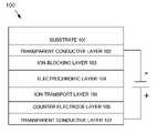
- FIG. 1depicts a first exemplary embodiment of an electrochromic device 100 according to the subject matter disclosed herein.
- Electrochromic device 100comprises a tantalum-nitride ion-blocking layer that is placed between a transparent conductive layer (ITO) and the working cathodic EC layer.
- ITOtransparent conductive layer
- One exemplary embodiment of a tantalum-nitride ion-blocking layerwould be formed have a thickness in the range of about 5 nm to about 50 nm.
- An alternative exemplary embodiment of a tantalum-nitride ion-blocking layerwould be formed to have a thickness of between about 5 nm to about 15 nm.
- electrochromic device 100comprises a substrate 101 , such as glass, a first transparent conductive layer 102 that is formed in a well-known manner on substrate 101 , an ion-blocking layer 103 that is formed in a well-known manner on first transparent conductive layer 102 , a transparent-to-reflective electrochromic (EC) layer 104 that is formed in a well-known manner on ion-blocking layer 103 , an ion-transport layer 105 that is formed in a well-known manner on transparent-to-reflective EC layer 104 , a counter electrode layer 106 that is formed in a well-known manner on ion-transport layer 105 , and a second transparent conductive layer 107 that is formed in a well-known manner on counter electrode layer 106 .
- the voltage depicted as being applied between the conductive layersrepresents a user-controlled electrical potential for controlling the electrochromic reaction of the device.
- FIG. 2depicts a second exemplary embodiment of an electrochromic device 200 according to the subject matter disclosed herein.
- Electrochromic device 200comprises a tantalum-oxide ion-blocking layer that is formed between a first transparent conductive layer and the working cathodic EC layer, and a tantalum-oxide ion-blocking layer that is formed between the counter-electrode layer and a second transparent conductive layer.
- One exemplary embodiment of a tantalum-nitride ion-blocking layerwould be formed have a thickness in the range of about 5 nm to about 50 nm.
- An alternative exemplary embodiment of a tantalum-nitride ion-blocking layerwould be formed to have a thickness of between about 5 nm to about 15 nm.
- electrochromic device 200comprises a substrate 201 , such as glass, a first transparent conductive layer 202 that is formed in a well-known manner on substrate 201 , an ion-blocking layer 203 that is formed in a well-known manner on first transparent conductive layer 202 , a transparent-to-reflective electrochromic (EC) layer 204 that is formed in a well-known manner on ion-blocking layer 203 , an ion-transport layer 205 that is formed in a well-known manner on transparent-to-reflective EC layer 204 , a counter-electrode layer 206 that is formed in a well-known manner on ion-transport layer 205 , a second ion-blocking layer 207 that is formed in a well-known manner on counter-electrode layer 206 , and a second transparent conductive layer 208 that is formed in a well-known manner on second ion-blocking layer 207 .
- ECtransparent-to-re
- An electrically non-conductive nitride or oxynitride compositioncould also be used as an ion diffusion barrier overlayer on top of the second transparent conductive layer (layer 208 ) to limit the tendency of lithium ions to diffuse to the top surface of the top electrode where conversion of the mobile ions to a carbonate, a hydroxide and/or an oxide composition would result from exposure to an air atmosphere, and would act like a “sink” for the mobile ions, thereby drawing the mobile ions away from the active electrochromic layers.
- the ion diffusion barrier overlayeris formed to have a thickness of about 5 nm to about 150 nm. In another exemplary embodiment, the ion diffusion barrier overlayer is formed to have a thickness of about 5 nm to about 10 nm.
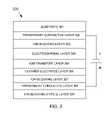
- FIG. 3depicts a third exemplary embodiment of an electrochromic device 300 according to the subject matter disclosed herein.
- Electrochromic device 300is similar to electrochromic device 200 , but further comprises a type-2 ion-blocking layer that is formed on the second transparent conductive layer.
- electrochromic device 300comprises a substrate 301 , such as glass, a first transparent conductive layer 302 that is formed in a well-known manner on substrate 301 , an ion-blocking layer 303 that is formed in a well-known manner on first transparent conductive layer 302 , a transparent-to-reflective electrochromic (EC) layer 304 that is formed in a well-known manner on ion-blocking layer 303 , an ion-transport layer 305 that is formed in a well-known manner on transparent-to-reflective EC layer 304 , a counter-electrode layer 306 that is formed in a well-known manner on ion-transport layer 305 , a second ion-blocking layer 307 that is formed in a well-known manner on counter-electrode layer 306 , a second transparent conductive layer 308 that is formed in a well-known manner on second ion-blocking layer 307 , and a Type-2 ion
- Electrochromic device 400is similar to electrochromic device 100 , but comprises an electrically conductive nitride layer in place of a transparent conductive layer formed from, for example, ITO.
- FIG. 4depicts a fourth exemplary embodiment of an electrochromic device 400 according to the subject matter disclosed herein.
- electrochromic device 400comprises a substrate 401 , such as glass, a first electrically conductive nitride layer 402 that is formed in a well-known manner on substrate 401 , a transparent-to-reflective electrochromic (EC) layer 403 that is formed in a well-known manner on electrically conductive nitride layer 402 , an ion-transport layer 404 that is formed in a well-known manner on transparent-to-reflective EC layer 403 , a counter electrode layer 405 that is formed in a well-known manner on ion-transport layer 404 , and a second electrically conductive nitride layer 406 that is formed in a well-known manner on counter electrode layer 405 .
- the voltage depicted as being applied between the conductive layersrepresents a user-controlled electrical potential for controlling the electrochromic reaction of the device.
- an electrically conductive nitride layersuch as tantalum nitride layer
- an electrically conductive nitride layerwould be formed have a thickness in the range of about 5 nm to about 50 nm.
- each of the four exemplary embodiments of FIGS. 1-4are depicted as being formed with a substrate at the “top” of the optical stack, it should be understood that each of the four exemplary embodiments could be formed with the substrate at the “bottom” of the optical stack. Additionally, while each of the exemplary embodiments of FIGS. 1-3 are depicted comprising a transparent conductive layer formed from ITO, FTO, AZO and/or ZITO, it should be understood that each of the exemplary embodiments could be formed so that one of the transparent conductive layers is formed from tantalum nitride.
Landscapes
- Physics & Mathematics (AREA)
- Nonlinear Science (AREA)
- General Physics & Mathematics (AREA)
- Optics & Photonics (AREA)
- Electrochromic Elements, Electrophoresis, Or Variable Reflection Or Absorption Elements (AREA)
Abstract
Description

4H2O+4e−=2H2+4OH−−1.6V
4OH−=2H2O+O2+4e−+0.80V
2H2O=2H2(at cathode)+O2(at anode)−0.8V.
Claims (31)
Priority Applications (1)
| Application Number | Priority Date | Filing Date | Title |
|---|---|---|---|
| US12/165,598US7679810B2 (en) | 2008-06-30 | 2008-06-30 | Electrical characteristics of electrochromic devices |
Applications Claiming Priority (1)
| Application Number | Priority Date | Filing Date | Title |
|---|---|---|---|
| US12/165,598US7679810B2 (en) | 2008-06-30 | 2008-06-30 | Electrical characteristics of electrochromic devices |
Publications (2)
| Publication Number | Publication Date |
|---|---|
| US20090323161A1 US20090323161A1 (en) | 2009-12-31 |
| US7679810B2true US7679810B2 (en) | 2010-03-16 |
Family
ID=41447047
Family Applications (1)
| Application Number | Title | Priority Date | Filing Date |
|---|---|---|---|
| US12/165,598Expired - Fee RelatedUS7679810B2 (en) | 2008-06-30 | 2008-06-30 | Electrical characteristics of electrochromic devices |
Country Status (1)
| Country | Link |
|---|---|
| US (1) | US7679810B2 (en) |
Cited By (15)
| Publication number | Priority date | Publication date | Assignee | Title |
|---|---|---|---|---|
| US20120218620A1 (en)* | 2008-06-06 | 2012-08-30 | Applied Materials, Inc. | Electrochromic Devices |
| US20120243068A1 (en)* | 2011-03-25 | 2012-09-27 | J Touch Corporation | Electrochromic apparatus |
| US20160085131A1 (en)* | 2010-12-15 | 2016-03-24 | Switch Materials, Inc. | Variable transmittance optical devices |
| US9880440B2 (en) | 2013-03-01 | 2018-01-30 | Alliance For Sustainable Energy, Llc | Electrochromic devices and related products and methods |
| US10222674B2 (en) | 2016-04-19 | 2019-03-05 | Sage Electrochromics, Inc. | Electrochromic device including a transparent conductive oxide layer and a bus bar and a process of forming the same |
| US20220055943A1 (en)* | 2009-03-31 | 2022-02-24 | View, Inc. | Fabrication of low defectivity electrochromic devices |
| US11714327B2 (en) | 2017-09-12 | 2023-08-01 | Sage Electrochromics, Inc. | Non-light-emitting variable transmission device and a method of forming the same |
| US11891327B2 (en) | 2014-05-02 | 2024-02-06 | View, Inc. | Fabrication of low defectivity electrochromic devices |
| US11898233B2 (en) | 2009-03-31 | 2024-02-13 | View, Inc. | Electrochromic devices |
| US11960188B2 (en) | 2014-11-26 | 2024-04-16 | View, Inc. | Counter electrode for electrochromic devices |
| US11966140B2 (en) | 2009-03-31 | 2024-04-23 | View, Inc. | Counter electrode for electrochromic devices |
| US12043890B2 (en) | 2009-03-31 | 2024-07-23 | View, Inc. | Electrochromic devices |
| US12209048B2 (en) | 2009-03-31 | 2025-01-28 | View, Inc. | Counter electrode for electrochromic devices |
| US12353109B2 (en) | 2009-12-22 | 2025-07-08 | View Operating Corporation | Electrochromic cathode materials |
| US12443085B2 (en) | 2024-03-20 | 2025-10-14 | View Operating Corporation | Counter electrode for electrochromic devices |
Families Citing this family (24)
| Publication number | Priority date | Publication date | Assignee | Title |
|---|---|---|---|---|
| US9007674B2 (en)* | 2011-09-30 | 2015-04-14 | View, Inc. | Defect-mitigation layers in electrochromic devices |
| US9723723B2 (en)* | 2009-03-31 | 2017-08-01 | View, Inc. | Temperable electrochromic devices |
| US11599003B2 (en) | 2011-09-30 | 2023-03-07 | View, Inc. | Fabrication of electrochromic devices |
| US12061402B2 (en) | 2011-12-12 | 2024-08-13 | View, Inc. | Narrow pre-deposition laser deletion |
| US10802371B2 (en) | 2011-12-12 | 2020-10-13 | View, Inc. | Thin-film devices and fabrication |
| US11865632B2 (en) | 2011-12-12 | 2024-01-09 | View, Inc. | Thin-film devices and fabrication |
| US12403676B2 (en) | 2011-12-12 | 2025-09-02 | View Operating Corporation | Thin-film devices and fabrication |
| CN102929063B (en)* | 2012-11-27 | 2014-07-30 | 高宏军 | Electrochromic device based on nano particles and preparation method thereof |
| JP6303068B2 (en)* | 2014-07-31 | 2018-03-28 | セイジ・エレクトロクロミクス,インコーポレイテッド | Controlled heating for electrochromic devices |
| US12235560B2 (en) | 2014-11-25 | 2025-02-25 | View, Inc. | Faster switching electrochromic devices |
| CN112615135B (en) | 2014-11-25 | 2024-12-10 | 唯景公司 | Method and device for personalizing the settings of a building area |
| US20220019117A1 (en)* | 2014-11-25 | 2022-01-20 | View, Inc. | Electromagnetic-shielding electrochromic windows |
| US11114742B2 (en) | 2014-11-25 | 2021-09-07 | View, Inc. | Window antennas |
| US10969645B2 (en) | 2015-03-20 | 2021-04-06 | View, Inc. | Faster switching low-defect electrochromic windows |
| CN107305307A (en)* | 2016-04-20 | 2017-10-31 | 吉晟光电(深圳)有限公司 | A kind of intelligent optical filter and its preparation technology and application |
| CN109121433A (en)* | 2016-05-09 | 2019-01-01 | Sage电致变色显示有限公司 | Comprising for preventing the device of Ion transfer electrochromic device and and forming method thereof |
| CN111108434A (en)* | 2017-05-03 | 2020-05-05 | 基内斯恰技术股份有限公司 | Flexible and multilayer electrochromic device and method of manufacturing the same |
| CN109100897B (en)* | 2018-09-27 | 2021-12-21 | 江西沃格光电股份有限公司 | Electrochromic film and method for producing electrochromic film |
| CN111650796B (en)* | 2019-03-04 | 2022-03-25 | 济南嘉源电子有限公司 | Flexible display screen capable of avoiding color development and fading electric attenuation |
| EP3966963A2 (en) | 2019-05-09 | 2022-03-16 | View, Inc. | Antenna systems for controlled coverage in buildings |
| US12176596B2 (en) | 2019-05-31 | 2024-12-24 | View, Inc. | Building antenna |
| US11703737B2 (en) | 2020-02-12 | 2023-07-18 | Sage Electrochromics, Inc. | Forming electrochromic stacks using at most one metallic lithium deposition station |
| CN113189811A (en)* | 2021-04-22 | 2021-07-30 | 维沃移动通信(杭州)有限公司 | Display panel and electronic device |
| CN115857241B (en)* | 2022-11-25 | 2025-08-29 | 深圳市华科创智技术股份有限公司 | An electrochromic device containing a transparent CdO layer |
Citations (5)
| Publication number | Priority date | Publication date | Assignee | Title |
|---|---|---|---|---|
| US5133594A (en)* | 1990-07-19 | 1992-07-28 | Tufts University | Transparent ion-blocking layer for electrochromic windows |
| US5532869A (en) | 1994-04-29 | 1996-07-02 | Tufts University | Transparent, electrically-conductive, ion-blocking layer for electrochromic windows |
| US6647166B2 (en) | 2000-08-17 | 2003-11-11 | The Regents Of The University Of California | Electrochromic materials, devices and process of making |
| US6773944B2 (en)* | 2001-11-07 | 2004-08-10 | Semiconductor Energy Laboratory Co., Ltd. | Method of manufacturing a semiconductor device |
| US7042615B2 (en) | 2002-05-17 | 2006-05-09 | The Regents Of The University Of California | Electrochromic devices based on lithium insertion |
- 2008
- 2008-06-30USUS12/165,598patent/US7679810B2/ennot_activeExpired - Fee Related
Patent Citations (5)
| Publication number | Priority date | Publication date | Assignee | Title |
|---|---|---|---|---|
| US5133594A (en)* | 1990-07-19 | 1992-07-28 | Tufts University | Transparent ion-blocking layer for electrochromic windows |
| US5532869A (en) | 1994-04-29 | 1996-07-02 | Tufts University | Transparent, electrically-conductive, ion-blocking layer for electrochromic windows |
| US6647166B2 (en) | 2000-08-17 | 2003-11-11 | The Regents Of The University Of California | Electrochromic materials, devices and process of making |
| US6773944B2 (en)* | 2001-11-07 | 2004-08-10 | Semiconductor Energy Laboratory Co., Ltd. | Method of manufacturing a semiconductor device |
| US7042615B2 (en) | 2002-05-17 | 2006-05-09 | The Regents Of The University Of California | Electrochromic devices based on lithium insertion |
Non-Patent Citations (4)
| Title |
|---|
| D.C. Nguyen et al., Effect of film thickness on the electrical properties of tantalum nitride thin films deposited on SiO2/Si substrates for -type attenuator applications,Journal of Vacuum Science & Technology B: Microelectronics and Nanometer Structures, May 2006, vol. 24, Issue 3, pp. 1398 1401. |
| H.B. Nie et al., Structural and electrical properties of tantalum nitride thin films fabricated by using reactive radio frequency magnetron sputtering, http://arxiv.org/ftp/cond-mat/papers/0305/0305683.pdf, May 29, 2003. |
| S.A. Bashar, Study of Indium Tin Oxide (ITO) for Novel Optoelectrical Devices, Ph.D. Ph.D thesis, www.betelco.com/sb/phd/index.html, 1998. |
| T. Waechtler et al., Optical Properties of Sputtered Tantalum Nitride Films Determined by Spectroscopic Ellipsometry, http://archiv.tu-chemnitz.de/pub/2006/0032/data/ellips.pdf, Mar. 16, 2006. |
Cited By (22)
| Publication number | Priority date | Publication date | Assignee | Title |
|---|---|---|---|---|
| US8693078B2 (en)* | 2008-06-06 | 2014-04-08 | Applied Materials, Inc. | Electrochromic devices |
| US20120218620A1 (en)* | 2008-06-06 | 2012-08-30 | Applied Materials, Inc. | Electrochromic Devices |
| US12043890B2 (en) | 2009-03-31 | 2024-07-23 | View, Inc. | Electrochromic devices |
| US11947232B2 (en) | 2009-03-31 | 2024-04-02 | View, Inc. | Fabrication of low defectivity electrochromic devices |
| US11966140B2 (en) | 2009-03-31 | 2024-04-23 | View, Inc. | Counter electrode for electrochromic devices |
| US11898233B2 (en) | 2009-03-31 | 2024-02-13 | View, Inc. | Electrochromic devices |
| US12242163B2 (en)* | 2009-03-31 | 2025-03-04 | View, Inc. | Fabrication of low defectivity electrochromic devices |
| US20220055943A1 (en)* | 2009-03-31 | 2022-02-24 | View, Inc. | Fabrication of low defectivity electrochromic devices |
| US12209048B2 (en) | 2009-03-31 | 2025-01-28 | View, Inc. | Counter electrode for electrochromic devices |
| US12366784B2 (en) | 2009-12-22 | 2025-07-22 | View Operating Corporation | Electrochromic cathode materials |
| US12353109B2 (en) | 2009-12-22 | 2025-07-08 | View Operating Corporation | Electrochromic cathode materials |
| US20160085131A1 (en)* | 2010-12-15 | 2016-03-24 | Switch Materials, Inc. | Variable transmittance optical devices |
| US10139695B2 (en)* | 2010-12-15 | 2018-11-27 | Switch Materials, Inc. | Variable transmittance optical devices |
| US20120243068A1 (en)* | 2011-03-25 | 2012-09-27 | J Touch Corporation | Electrochromic apparatus |
| US10061176B2 (en) | 2013-03-01 | 2018-08-28 | Alliance For Sustainable Energy, Llc | Electrochromic devices and related products and methods |
| US9880440B2 (en) | 2013-03-01 | 2018-01-30 | Alliance For Sustainable Energy, Llc | Electrochromic devices and related products and methods |
| US11891327B2 (en) | 2014-05-02 | 2024-02-06 | View, Inc. | Fabrication of low defectivity electrochromic devices |
| US11960188B2 (en) | 2014-11-26 | 2024-04-16 | View, Inc. | Counter electrode for electrochromic devices |
| US10788724B2 (en) | 2016-04-19 | 2020-09-29 | Sage Electrochromics, Inc. | Electrochromic device including a transparent conductive oxide layer and a bus bar and a process of forming the same |
| US10222674B2 (en) | 2016-04-19 | 2019-03-05 | Sage Electrochromics, Inc. | Electrochromic device including a transparent conductive oxide layer and a bus bar and a process of forming the same |
| US11714327B2 (en) | 2017-09-12 | 2023-08-01 | Sage Electrochromics, Inc. | Non-light-emitting variable transmission device and a method of forming the same |
| US12443085B2 (en) | 2024-03-20 | 2025-10-14 | View Operating Corporation | Counter electrode for electrochromic devices |
Also Published As
| Publication number | Publication date |
|---|---|
| US20090323161A1 (en) | 2009-12-31 |
Similar Documents
| Publication | Publication Date | Title |
|---|---|---|
| US7679810B2 (en) | Electrical characteristics of electrochromic devices | |
| US20230176439A1 (en) | Electrochromic devices and methods | |
| US10564506B2 (en) | Electrochromic device and method for making electrochromic device | |
| JP3353905B2 (en) | Electrochromic glass | |
| US8259380B2 (en) | Electrodes of electrochemical/electrically-driven devices | |
| JP5420818B2 (en) | Electrochromic device with improved ionic conductor layer | |
| US8031389B2 (en) | Reflection-controllable electrochromic device using a base metal as a transparent conductor | |
| US8102587B2 (en) | Electrochromic device having controlled infrared reflection | |
| US8274730B2 (en) | Glass type electrochemical/electrically controllable device with variable optical and/or energetic characteristic | |
| US7317566B2 (en) | Electrode with transparent series resistance for uniform switching of optical modulation devices | |
| US7961375B2 (en) | Multi-cell solid-state electrochromic device | |
| JP5233133B2 (en) | Electrochromic film | |
| JP2009545765A5 (en) | ||
| Lee et al. | Durability-enhanced monolithic inorganic electrochromic devices with tantalum-doped nickel oxide as a counter electrode | |
| Da Rocha et al. | Electrochromism of non-stoichiometric NiO thin film: as single layer and in full device | |
| US7333258B2 (en) | Electrochromic material | |
| JP2013545146A (en) | Electrochemical device with electrically controllable light and / or energy transmission characteristics | |
| US10996535B1 (en) | Electrochromic device with buffer layer(s) | |
| US5684619A (en) | Ruthenium oxide counterelectrode for electrochromic devices | |
| US5768004A (en) | Oxidatively coloring electrochromic material and electro-optical device using same | |
| Usha et al. | SIZO/Ag/SIZO/NiO sandwich film based smart window combining hybrid low emissivity and electrochromism for the dynamic control of solar radiation | |
| JP5902709B2 (en) | Electrochemical device with electrically controllable light and / or energy transmission characteristics | |
| US11988935B2 (en) | Bus bar design of an IGU with graded transmission state | |
| US12066734B1 (en) | Electrochromic device having various uses | |
| CN120019325A (en) | Electrochromic glass |
Legal Events
| Date | Code | Title | Description |
|---|---|---|---|
| AS | Assignment | Owner name:SOLADIGM, INC., CALIFORNIA Free format text:ASSIGNMENT OF ASSIGNORS INTEREST;ASSIGNORS:FUSS, EUGENE ANTHONY;PHILLIPS, ROGER W.;NGUYEN, PAUL P.;REEL/FRAME:021175/0461 Effective date:20080630 Owner name:SOLADIGM, INC.,CALIFORNIA Free format text:ASSIGNMENT OF ASSIGNORS INTEREST;ASSIGNORS:FUSS, EUGENE ANTHONY;PHILLIPS, ROGER W.;NGUYEN, PAUL P.;REEL/FRAME:021175/0461 Effective date:20080630 | |
| STCF | Information on status: patent grant | Free format text:PATENTED CASE | |
| AS | Assignment | Owner name:VIEW, INC., CALIFORNIA Free format text:CHANGE OF NAME;ASSIGNOR:SOLADIGM, INC.;REEL/FRAME:029422/0119 Effective date:20121108 | |
| FEPP | Fee payment procedure | Free format text:PAT HOLDER NO LONGER CLAIMS SMALL ENTITY STATUS, ENTITY STATUS SET TO UNDISCOUNTED (ORIGINAL EVENT CODE: STOL); ENTITY STATUS OF PATENT OWNER: LARGE ENTITY | |
| FPAY | Fee payment | Year of fee payment:4 | |
| AS | Assignment | Owner name:THE BANK OF NEW YORK MELLON TRUST COMPANY, N.A., AS COLLATERAL AGENT, CALIFORNIA Free format text:SECURITY INTEREST;ASSIGNOR:VIEW, INC.;REEL/FRAME:038440/0749 Effective date:20160415 Owner name:THE BANK OF NEW YORK MELLON TRUST COMPANY, N.A., A Free format text:SECURITY INTEREST;ASSIGNOR:VIEW, INC.;REEL/FRAME:038440/0749 Effective date:20160415 | |
| AS | Assignment | Owner name:THE BANK OF NEW YORK MELLON TRUST COMPANY, N.A., CALIFORNIA Free format text:SECURITY INTEREST;ASSIGNOR:VIEW, INC.;REEL/FRAME:041493/0859 Effective date:20170125 Owner name:THE BANK OF NEW YORK MELLON TRUST COMPANY, N.A., C Free format text:SECURITY INTEREST;ASSIGNOR:VIEW, INC.;REEL/FRAME:041493/0859 Effective date:20170125 | |
| AS | Assignment | Owner name:VIEW, INC., CALIFORNIA Free format text:RELEASE BY SECURED PARTY;ASSIGNOR:THE BANK OF NEW YORK MELLON TRUST COMPANY, N.A.;REEL/FRAME:041549/0094 Effective date:20170125 | |
| MAFP | Maintenance fee payment | Free format text:PAYMENT OF MAINTENANCE FEE, 8TH YEAR, LARGE ENTITY (ORIGINAL EVENT CODE: M1552) Year of fee payment:8 | |
| AS | Assignment | Owner name:VIEW, INC., CALIFORNIA Free format text:TERMINATION AND RELEASE OF SECURITY INTEREST;ASSIGNOR:THE BANK OF NEW YORK MELLON TRUST COMPANY, N.A.;REEL/FRAME:049100/0817 Effective date:20190321 | |
| AS | Assignment | Owner name:GREENSILL CAPITAL (UK) LIMITED, ENGLAND Free format text:SECURITY INTEREST;ASSIGNOR:VIEW, INC.;REEL/FRAME:051012/0359 Effective date:20191023 | |
| AS | Assignment | Owner name:VIEW, INC., CALIFORNIA Free format text:RELEASE BY SECURED PARTY;ASSIGNOR:GREENSILL CAPITAL (UK) LIMITED;REEL/FRAME:055542/0516 Effective date:20210308 | |
| FEPP | Fee payment procedure | Free format text:MAINTENANCE FEE REMINDER MAILED (ORIGINAL EVENT CODE: REM.); ENTITY STATUS OF PATENT OWNER: LARGE ENTITY | |
| LAPS | Lapse for failure to pay maintenance fees | Free format text:PATENT EXPIRED FOR FAILURE TO PAY MAINTENANCE FEES (ORIGINAL EVENT CODE: EXP.); ENTITY STATUS OF PATENT OWNER: LARGE ENTITY | |
| STCH | Information on status: patent discontinuation | Free format text:PATENT EXPIRED DUE TO NONPAYMENT OF MAINTENANCE FEES UNDER 37 CFR 1.362 | |
| FP | Lapsed due to failure to pay maintenance fee | Effective date:20220316 | |
| FEPP | Fee payment procedure | Free format text:ENTITY STATUS SET TO SMALL (ORIGINAL EVENT CODE: SMAL); ENTITY STATUS OF PATENT OWNER: SMALL ENTITY | |
| FEPP | Fee payment procedure | Free format text:ENTITY STATUS SET TO UNDISCOUNTED (ORIGINAL EVENT CODE: BIG.); ENTITY STATUS OF PATENT OWNER: LARGE ENTITY | |
| AS | Assignment | Owner name:VIEW OPERATING CORPORATION, CALIFORNIA Free format text:MERGER AND CHANGE OF NAME;ASSIGNORS:VIEW, INC.;PVMS MERGER SUB, INC.;VIEW OPERATING CORPORATION;REEL/FRAME:069743/0586 Effective date:20210308 |