US7679808B2 - Portable electronic device with an integrated switchable mirror - Google Patents
Portable electronic device with an integrated switchable mirrorDownload PDFInfo
- Publication number
- US7679808B2 US7679808B2US11/306,939US30693906AUS7679808B2US 7679808 B2US7679808 B2US 7679808B2US 30693906 AUS30693906 AUS 30693906AUS 7679808 B2US7679808 B2US 7679808B2
- Authority
- US
- United States
- Prior art keywords
- electronic device
- switchable mirror
- display
- portable electronic
- switched
- Prior art date
- Legal status (The legal status is an assumption and is not a legal conclusion. Google has not performed a legal analysis and makes no representation as to the accuracy of the status listed.)
- Active, expires
Links
Images


Classifications
- H—ELECTRICITY
- H04—ELECTRIC COMMUNICATION TECHNIQUE
- H04M—TELEPHONIC COMMUNICATION
- H04M1/00—Substation equipment, e.g. for use by subscribers
- H04M1/02—Constructional features of telephone sets
- H04M1/21—Combinations with auxiliary equipment, e.g. with clocks or memoranda pads
- H—ELECTRICITY
- H04—ELECTRIC COMMUNICATION TECHNIQUE
- H04M—TELEPHONIC COMMUNICATION
- H04M1/00—Substation equipment, e.g. for use by subscribers
- H04M1/02—Constructional features of telephone sets
- H04M1/0202—Portable telephone sets, e.g. cordless phones, mobile phones or bar type handsets
- H04M1/026—Details of the structure or mounting of specific components
- H04M1/0266—Details of the structure or mounting of specific components for a display module assembly
Definitions
- the present inventionis related to switchable mirrors and their integration into portable electronic devices, such as cellular telephones, sometimes called cell or mobile phones, personal digital assistants (PDAs), personal music/video players, such as MP3 players and IPods, and the like. Switchable mirrors might also be integrated into larger electronic devices, such as laptop computers.
- portable electronic devicessuch as cellular telephones, sometimes called cell or mobile phones, personal digital assistants (PDAs), personal music/video players, such as MP3 players and IPods, and the like.
- PDAspersonal digital assistants
- MP3 playerssuch as MP3 players and IPods
- Switchable mirrorsmight also be integrated into larger electronic devices, such as laptop computers.
- Such portable and in most cases, handheld, electronic devicesare becoming more and more common in modern society as their ease of use and functionalities increase.
- some current cell phoneswhile no larger than one's palm, operate more like pocket-size computers.
- other functions of such telephonesinclude the ability to send and receive e-mail, to “surf the Web” (i.e., to access the WorldWide Web), to manage schedules with personal calendars, to take and send digital photographs, to act as a platform for games, and other activities.
- Future projected functions of portable electronic devicesinclude the wireless reception of television and music signals, the so-called mobile media.
- the merger of functionsoften blurs the terminology of a particular device. Whether a combination of cellular telephone and a personal digital assistant is called a cellular telephone with PDA features or a PDA with cell phone features is often a reflection of marketing rather than a weighing of device functions.
- GPSGlobal Positioning Satellite
- the present inventionprovides for a portable electronic device which has a housing sized to be held in a person's hand; a display mounted in the housing, the display showing the state or operation of the portable electronic device; and a switchable mirror covering the display and capable of switching from a transparent state to a reflecting state responsive to a switch in the portable electronic device.
- the displayis switched off when the switchable mirror switches to its reflecting state.
- the switchable mirroris switched to its reflecting state when the portable electronic device is switched off.
- the portable electronic devicecan be a cellular telephone, a PDA, a music player, and even a GPS device.
- the present inventioncan also provide for a larger portable electronic device, such as a laptop computer, with a switchable mirror covering the display of the laptop computer and capable of switching from a transparent state to a reflecting state.
- FIG. 1is a representation of a portable electronic device with a switchable mirror, according to one embodiment of the present invention
- FIG. 2is an exploded detailed view of the elements of a flat screen display with switchable mirror, according to one embodiment of the present invention.
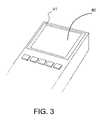
- FIG. 3is detailed view of switchable mirror covering a flat screen display partially, according to another embodiment of the present invention.
- portable electronic devicesemploying a flat screen display, typically a liquid crystal display, or LCD
- a laptop computer and a cellular telephonehave become necessities.
- the portable electronic deviceprovides the user with a convenient and inconspicuous on-demand mirror.
- the user of such a devicecan check his or her appearance after using a cellular telephone, for example, without carrying a separate mirror.
- the mirrorswitches to its transparent state so that the display is visible.
- switchable mirror technologiesThere are different switchable mirror technologies which have been recently developed. Early practical switchable mirror are based on hydrogen-induced phase transition in rare earth metals. Subsequently significant progress toward lower-cost, greater reliability and improved performance switchable mirrors has been made by transition metal-based switchable mirrors, or TMSM. Thin films of an active transition metal material, bonded to glass substrates, can switch reversibly between reflecting and transparent states, either by exposure to hydrogen or by application of an electric current. The TMSM film is laminated between electrodes with other electrolytes. In many cases, the active film can also be one of electrodes. These types of devices are also known as electrochromic devices.
- switchable mirrorsAnother development in switchable mirrors is based on lithium ion insertion that is even more stable and potentially lower cost than TMSM. As such, large-scale application, such as building windows, of this technology is now being contemplated. Of course, the present invention uses switchable mirrors configured to switch electrically on a far smaller scale.
- a switchable mirror 10is attached to the surface of an LCD 12 which is mounted on the palm-sized housing 15 of a representative portable electronic device 11 illustrated in FIG. 1 .
- the housing 15also holds a keypad 16 .
- the area of the switchable mirror 10is equal to the area of the display 12 so that the mirror 10 fits over the LCD 12 .
- the power source of the portable electronic device 11which may be either a battery or a source external to the device 10 , also provides power to the switchable mirror 10 .
- An electronic switch represented by the switch 14commanded by either a dedicated key 13 of the keypad 16 or device software turns the power on or off to the switchable mirror 10 to change its optical property from a (mostly) transparent state to a (mostly) reflecting state.
- the switchable mirror 10is in its transparent state, the underlying display is visible and the portable electronic device 11 functions normally.
- the switchable mirror 10is in its reflecting state, the underlying display can be powered off and the portable electronic device 11 functions as a mirror.
- the LCD 32 of the portable electronic device 31is formed by a glass sheet 26 upon which is deposited a first set of LCD electrodes, such as a defined layer of indium-tin oxide (ITO) and a polarizing filter sheet; liquid crystal material 25 ; and a glass sheet 24 with a second set of LCD electrodes (and a set of thin film transistors). Insulating elastic bushings (not shown) around the edges of the glass sheets 24 and 26 separate the glass sheets and confine the liquid crystal material 25 between them.
- a polarizing filter sheet 21completes the LCD.
- the elements of the switchable mirror 30are arranged between the polarizing filter sheet 21 and the glass sheet 24 .
- Upon the inner surface (the side facing the display) of the sheet 22is deposited a layer of electrochromic film and the mirror electrodes.
- An electrolyte layer 23is placed against the electrochromic film.
- the counter electrode for the switchable mirroris deposited on the outer surface of the glass sheet 24 .
- the switch (not shown in FIG. 2 ) for the switchable mirror 30is activated via a dedicated key, such as key 13 in FIG. 1 , or by a combination of keystrokes on the key pad of the portable electronic device 31 .
- the optical property of the switchable mirrorchanges between a transparent state and a reflecting state.
- the switchable mirroris in its reflecting state, the display of the device is turned off since the display can no longer be seen. Power is saved.
- the switchable mirrorit may desirable that when the portable electronic device itself is turned off, the switchable mirror be in its reflecting state. This is achieved by the appropriate selection of the electrochromic material, such as a Ni—Mg alloy, and the operation of the mirror switch when the device is turned off. That is, the electrochromic material is in its reflecting state when there is no voltage applied to it. This feature is particularly useful for outdoor recreation devices, such as GPS devices. Even if the device is dead, the reflecting mirror serves as a useful signaling device to search parties, for example.
- the switchable mirrorhas been described as covering the entire surface of the underlying display of the portable electronic device.
- the mirrorcan extend partially over the display surface.
- FIG. 3shows such an arrangement.
- the switchable mirror 40covers the center of the display surface so that a marginal portion 41 of the display surface extends around the mirror 40 .
- Nearly all LCDsare backlit by fluorescent bulbs currently and by LEDs (Light-Emitting Diodes) in the near future to ensure a bright display. With the increasing luminescence of the backlighting, especially by LEDs, the display of the portable electronic device can provide a “lighted vanity mirror” when the switchable mirror 40 is switched to its reflecting state.
- the switchable mirroris flat. If the mirror is concave by having the switchable mirror including a concave surface facing away from the display, the switchable mirror in its reflecting state is a magnifier allowing the viewer to better see his or her reflection. Such mirrors allow not only detailed reflections of the viewer for vanity purposes, but are also useful for medical or hygienic purposes. Contact lens users can better see their eyes to insert their lenses or to adjust lenses which have slipped from their proper locations in the eye.
- the present inventionhas many uses and can be adapted to many different portable electronic devices.
Landscapes
- Engineering & Computer Science (AREA)
- Signal Processing (AREA)
- Devices For Indicating Variable Information By Combining Individual Elements (AREA)
- Telephone Set Structure (AREA)
Abstract
Description
Claims (14)
Priority Applications (2)
| Application Number | Priority Date | Filing Date | Title |
|---|---|---|---|
| US11/306,939US7679808B2 (en) | 2006-01-17 | 2006-01-17 | Portable electronic device with an integrated switchable mirror |
| US12/698,432US20100134863A1 (en) | 2006-01-17 | 2010-02-02 | Portable electronic device with an integrated switchable mirror |
Applications Claiming Priority (1)
| Application Number | Priority Date | Filing Date | Title |
|---|---|---|---|
| US11/306,939US7679808B2 (en) | 2006-01-17 | 2006-01-17 | Portable electronic device with an integrated switchable mirror |
Related Child Applications (1)
| Application Number | Title | Priority Date | Filing Date |
|---|---|---|---|
| US12/698,432ContinuationUS20100134863A1 (en) | 2006-01-17 | 2010-02-02 | Portable electronic device with an integrated switchable mirror |
Publications (2)
| Publication Number | Publication Date |
|---|---|
| US20080186560A1 US20080186560A1 (en) | 2008-08-07 |
| US7679808B2true US7679808B2 (en) | 2010-03-16 |
Family
ID=39675893
Family Applications (2)
| Application Number | Title | Priority Date | Filing Date |
|---|---|---|---|
| US11/306,939Active2028-05-08US7679808B2 (en) | 2006-01-17 | 2006-01-17 | Portable electronic device with an integrated switchable mirror |
| US12/698,432AbandonedUS20100134863A1 (en) | 2006-01-17 | 2010-02-02 | Portable electronic device with an integrated switchable mirror |
Family Applications After (1)
| Application Number | Title | Priority Date | Filing Date |
|---|---|---|---|
| US12/698,432AbandonedUS20100134863A1 (en) | 2006-01-17 | 2010-02-02 | Portable electronic device with an integrated switchable mirror |
Country Status (1)
| Country | Link |
|---|---|
| US (2) | US7679808B2 (en) |
Cited By (9)
| Publication number | Priority date | Publication date | Assignee | Title |
|---|---|---|---|---|
| US20090231273A1 (en)* | 2006-05-31 | 2009-09-17 | Koninklijke Philips Electronics N.V. | Mirror feedback upon physical object selection |
| US20120044233A1 (en)* | 2009-03-27 | 2012-02-23 | Koninklijke Philips Electronics N.V. | Device for placement in front of a display device |
| US8731245B2 (en) | 2012-03-07 | 2014-05-20 | Xerox Corporation | Multiple view transportation imaging systems |
| US9126434B2 (en) | 2014-01-22 | 2015-09-08 | Ricoh Company, Ltd. | Radiant heat control with adjustable reflective element |
| US10054857B2 (en) | 2016-11-17 | 2018-08-21 | Xerox Corporation | Switchable mirror lens system for redirecting laser energy during periods of non-printing |
| US10067362B2 (en) | 2016-11-17 | 2018-09-04 | Xerox Corporation | Switchable mirror system for reflecting laser input during printing |
| US10228603B2 (en) | 2014-07-24 | 2019-03-12 | Samsung Electronics Co., Ltd. | Electro-chromic panel capable of selectively making transparent area and reflective area and method of operating the same, and display apparatus including the same and method of operating display apparatus |
| WO2020232204A1 (en) | 2019-05-14 | 2020-11-19 | Flex-N-Gate Advanced Product Development, Llc | Switchable mirror lens assembly |
| WO2020257606A1 (en) | 2019-06-21 | 2020-12-24 | Flex-N-Gate Advanced Productdevelopment, Llc | Segmented switchable mirror lamp assembly |
Families Citing this family (4)
| Publication number | Priority date | Publication date | Assignee | Title |
|---|---|---|---|---|
| US8363301B2 (en) | 2010-06-16 | 2013-01-29 | Electronics And Telecommunications Research Institute | Transparent smart light source capable of adjusting illumination direction |
| US10634910B2 (en)* | 2015-05-11 | 2020-04-28 | Electric Mirror, Llc | Apparatuses and methods for providing a vanishing viewing window within a mirror |
| US10585307B2 (en) | 2016-03-30 | 2020-03-10 | Motorola Mobility Llc | Display construct with integrated switchable mirror and corresponding systems and methods |
| WO2018047000A1 (en)* | 2016-09-08 | 2018-03-15 | Mohawk Innovations Limited | Optical device with electrochromic lens cap |
Citations (7)
| Publication number | Priority date | Publication date | Assignee | Title |
|---|---|---|---|---|
| US6437900B1 (en)* | 1999-04-20 | 2002-08-20 | Koninklijke Philips Electronics N.V. | Transflective display device |
| US7058252B2 (en)* | 2001-08-06 | 2006-06-06 | Ocuity Limited | Optical switching apparatus |
| US7057681B2 (en)* | 2002-06-24 | 2006-06-06 | Seiko Epson Corporation | Liquid crystal display with mirror mode having top reflective polarizer |
| US20070002422A1 (en)* | 2005-07-01 | 2007-01-04 | O'shaughnessy Dennis J | Transparent electrode for an electrochromic switchable cell |
| US7186015B2 (en)* | 2004-04-16 | 2007-03-06 | Polymore Circuit Technologies, Inc. | Backlight display system |
| US7268841B2 (en)* | 2002-07-04 | 2007-09-11 | Seiko Epson Corporation | Display device and electronic equipment having the same comprising a region for reflecting a polarized light and a region for absorbing the polarized light |
| US20090213568A1 (en)* | 2005-06-14 | 2009-08-27 | Koninklijke Philips Electronics N.V. | Multi view display device |
Family Cites Families (1)
| Publication number | Priority date | Publication date | Assignee | Title |
|---|---|---|---|---|
| US6647166B2 (en)* | 2000-08-17 | 2003-11-11 | The Regents Of The University Of California | Electrochromic materials, devices and process of making |
- 2006
- 2006-01-17USUS11/306,939patent/US7679808B2/enactiveActive
- 2010
- 2010-02-02USUS12/698,432patent/US20100134863A1/ennot_activeAbandoned
Patent Citations (7)
| Publication number | Priority date | Publication date | Assignee | Title |
|---|---|---|---|---|
| US6437900B1 (en)* | 1999-04-20 | 2002-08-20 | Koninklijke Philips Electronics N.V. | Transflective display device |
| US7058252B2 (en)* | 2001-08-06 | 2006-06-06 | Ocuity Limited | Optical switching apparatus |
| US7057681B2 (en)* | 2002-06-24 | 2006-06-06 | Seiko Epson Corporation | Liquid crystal display with mirror mode having top reflective polarizer |
| US7268841B2 (en)* | 2002-07-04 | 2007-09-11 | Seiko Epson Corporation | Display device and electronic equipment having the same comprising a region for reflecting a polarized light and a region for absorbing the polarized light |
| US7186015B2 (en)* | 2004-04-16 | 2007-03-06 | Polymore Circuit Technologies, Inc. | Backlight display system |
| US20090213568A1 (en)* | 2005-06-14 | 2009-08-27 | Koninklijke Philips Electronics N.V. | Multi view display device |
| US20070002422A1 (en)* | 2005-07-01 | 2007-01-04 | O'shaughnessy Dennis J | Transparent electrode for an electrochromic switchable cell |
Cited By (14)
| Publication number | Priority date | Publication date | Assignee | Title |
|---|---|---|---|---|
| US8749482B2 (en)* | 2006-05-31 | 2014-06-10 | Koninklijke Philips N.V. | Mirror feedback upon physical object selection |
| US20090231273A1 (en)* | 2006-05-31 | 2009-09-17 | Koninklijke Philips Electronics N.V. | Mirror feedback upon physical object selection |
| US20120044233A1 (en)* | 2009-03-27 | 2012-02-23 | Koninklijke Philips Electronics N.V. | Device for placement in front of a display device |
| US8686984B2 (en)* | 2009-03-27 | 2014-04-01 | Kkoninklijke Philips N.V. | Device for placement in front of a display device |
| US8731245B2 (en) | 2012-03-07 | 2014-05-20 | Xerox Corporation | Multiple view transportation imaging systems |
| US9126434B2 (en) | 2014-01-22 | 2015-09-08 | Ricoh Company, Ltd. | Radiant heat control with adjustable reflective element |
| US10228603B2 (en) | 2014-07-24 | 2019-03-12 | Samsung Electronics Co., Ltd. | Electro-chromic panel capable of selectively making transparent area and reflective area and method of operating the same, and display apparatus including the same and method of operating display apparatus |
| US10054857B2 (en) | 2016-11-17 | 2018-08-21 | Xerox Corporation | Switchable mirror lens system for redirecting laser energy during periods of non-printing |
| US10067362B2 (en) | 2016-11-17 | 2018-09-04 | Xerox Corporation | Switchable mirror system for reflecting laser input during printing |
| WO2020232204A1 (en) | 2019-05-14 | 2020-11-19 | Flex-N-Gate Advanced Product Development, Llc | Switchable mirror lens assembly |
| US11118749B2 (en) | 2019-05-14 | 2021-09-14 | Flex-N-Gate Advanced Product Development, Llc | Switchable mirror lens assembly |
| WO2020257606A1 (en) | 2019-06-21 | 2020-12-24 | Flex-N-Gate Advanced Productdevelopment, Llc | Segmented switchable mirror lamp assembly |
| US11204148B2 (en) | 2019-06-21 | 2021-12-21 | Flex-N-Gate Advanced Product Development, Llc | Segmented switchable mirror lamp assembly |
| US11608959B2 (en) | 2019-06-21 | 2023-03-21 | Flex-N-Gate Advanced Product Development, Llc | Segmented switchable mirror lamp assembly |
Also Published As
| Publication number | Publication date |
|---|---|
| US20080186560A1 (en) | 2008-08-07 |
| US20100134863A1 (en) | 2010-06-03 |
Similar Documents
| Publication | Publication Date | Title |
|---|---|---|
| US7679808B2 (en) | Portable electronic device with an integrated switchable mirror | |
| RU2642854C2 (en) | Method of notification | |
| US8174489B2 (en) | Dual-sided display for mobile device | |
| US7859617B2 (en) | Display with variable reflectivity | |
| US7853288B2 (en) | Sunlight illuminated and sunlight readable mobile phone | |
| US6574487B1 (en) | Communication device with a dual-sided liquid crystal display | |
| EP1324100A1 (en) | Portable terminal device having a display unit utilizing a holographic screen | |
| US20060146012A1 (en) | System and method for automatic display switching | |
| US7768605B2 (en) | Display stack-up for a mobile electronic device having internal and external displays | |
| JP2002122860A (en) | Liquid crystal display element | |
| US20070015554A1 (en) | Compact and durable thin smartphone | |
| US20070015553A1 (en) | Compact and durable clamshell smartphone | |
| US7221559B1 (en) | Multipurpose bumper system for a data processing apparatus | |
| US20100130271A1 (en) | Slider Form Factor Devices and Methods for Morphing Indicia Visible through a Transparent Member | |
| JP4202652B2 (en) | Liquid crystal display device and portable information terminal | |
| JP2001268186A (en) | Mobile unit with mobile phone function | |
| Akins | 33.1: Invited Paper: Displays for Hand‐Held Portable Electronic Products | |
| KR200214827Y1 (en) | Cellularphone having LCD | |
| KR20050077409A (en) | Mobile electronic apparatus capable of exchange of a display module | |
| KR20140098029A (en) | A mirror function having a smartphone | |
| KR20050035455A (en) | Slide type mobile communication terminal applying sub display device. | |
| KR20050050823A (en) | Portable mobile-phone with dual display divice | |
| WO2004019307A1 (en) | Flat panel display unit | |
| TW201126311A (en) | Foldable mobile device |
Legal Events
| Date | Code | Title | Description |
|---|---|---|---|
| AS | Assignment | Owner name:PANTECH & CURITEL COMMUNICATIONS, INC., KOREA, REP Free format text:ASSIGNMENT OF ASSIGNORS INTEREST;ASSIGNOR:KIM, NICOLE JURIE;REEL/FRAME:023186/0804 Effective date:20090818 Owner name:PANTECH & CURITEL COMMUNICATIONS, INC.,KOREA, REPU Free format text:ASSIGNMENT OF ASSIGNORS INTEREST;ASSIGNOR:KIM, NICOLE JURIE;REEL/FRAME:023186/0804 Effective date:20090818 | |
| FEPP | Fee payment procedure | Free format text:PAYOR NUMBER ASSIGNED (ORIGINAL EVENT CODE: ASPN); ENTITY STATUS OF PATENT OWNER: LARGE ENTITY | |
| STCF | Information on status: patent grant | Free format text:PATENTED CASE | |
| AS | Assignment | Owner name:PANTECH CO., LTD., KOREA, REPUBLIC OF Free format text:MERGER;ASSIGNOR:PANTECH & CURITEL COMMUNICATIONS, INC.;REEL/FRAME:025879/0708 Effective date:20091230 | |
| FEPP | Fee payment procedure | Free format text:PAYER NUMBER DE-ASSIGNED (ORIGINAL EVENT CODE: RMPN); ENTITY STATUS OF PATENT OWNER: LARGE ENTITY Free format text:PAYOR NUMBER ASSIGNED (ORIGINAL EVENT CODE: ASPN); ENTITY STATUS OF PATENT OWNER: LARGE ENTITY | |
| FPAY | Fee payment | Year of fee payment:4 | |
| AS | Assignment | Owner name:PANTECH INC., KOREA, REPUBLIC OF Free format text:DE-MERGER;ASSIGNOR:PANTECH CO., LTD.;REEL/FRAME:040001/0617 Effective date:20151022 Owner name:PANTECH CO., LTD., KOREA, REPUBLIC OF Free format text:MERGER;ASSIGNOR:PANTECH & CURITEL COMMUNICATIONS INC.;REEL/FRAME:040414/0617 Effective date:20091230 | |
| AS | Assignment | Owner name:PANTECH INC., KOREA, REPUBLIC OF Free format text:CORRECTIVE ASSIGNMENT TO REMOVE PATENT NUMBERS 6741868,7203514,7321764 AND 7505783 PREVIOUSLY RECORDED ON REEL 040001 FRAME 0617. ASSIGNOR(S) HEREBY CONFIRMS THE DE-MERGER;ASSIGNOR:PANTECH CO., LTD.;REEL/FRAME:041440/0549 Effective date:20151022 Owner name:PANTECH CO., LTD., KOREA, REPUBLIC OF Free format text:CORRECTIVE ASSIGNMENT TO CORRECT THE LISTED OF PATENTS PREVIOUSLY RECORDED AT REEL: 040414 FRAME: 0617. ASSIGNOR(S) HEREBY CONFIRMS THE ASSIGNMENT;ASSIGNOR:PANTECH & CURITEL COMMUNICATIONS INC.;REEL/FRAME:041472/0406 Effective date:20091230 | |
| FEPP | Fee payment procedure | Free format text:MAINTENANCE FEE REMINDER MAILED (ORIGINAL EVENT CODE: REM.) | |
| FEPP | Fee payment procedure | Free format text:7.5 YR SURCHARGE - LATE PMT W/IN 6 MO, LARGE ENTITY (ORIGINAL EVENT CODE: M1555) | |
| MAFP | Maintenance fee payment | Free format text:PAYMENT OF MAINTENANCE FEE, 8TH YEAR, LARGE ENTITY (ORIGINAL EVENT CODE: M1552) Year of fee payment:8 | |
| AS | Assignment | Owner name:PANTECH CORPORATION, KOREA, REPUBLIC OF Free format text:ASSIGNMENT OF ASSIGNORS INTEREST;ASSIGNOR:PANTECH INC.;REEL/FRAME:052662/0609 Effective date:20200506 | |
| MAFP | Maintenance fee payment | Free format text:PAYMENT OF MAINTENANCE FEE, 12TH YEAR, LARGE ENTITY (ORIGINAL EVENT CODE: M1553); ENTITY STATUS OF PATENT OWNER: LARGE ENTITY Year of fee payment:12 |