US7679627B2 - Controller and driver features for bi-stable display - Google Patents
Controller and driver features for bi-stable displayDownload PDFInfo
- Publication number
- US7679627B2 US7679627B2US11/097,819US9781905AUS7679627B2US 7679627 B2US7679627 B2US 7679627B2US 9781905 AUS9781905 AUS 9781905AUS 7679627 B2US7679627 B2US 7679627B2
- Authority
- US
- United States
- Prior art keywords
- frame
- display
- skip count
- array
- frames
- Prior art date
- Legal status (The legal status is an assumption and is not a legal conclusion. Google has not performed a legal analysis and makes no representation as to the accuracy of the status listed.)
- Expired - Fee Related, expires
Links
Images


Classifications
- G—PHYSICS
- G02—OPTICS
- G02F—OPTICAL DEVICES OR ARRANGEMENTS FOR THE CONTROL OF LIGHT BY MODIFICATION OF THE OPTICAL PROPERTIES OF THE MEDIA OF THE ELEMENTS INVOLVED THEREIN; NON-LINEAR OPTICS; FREQUENCY-CHANGING OF LIGHT; OPTICAL LOGIC ELEMENTS; OPTICAL ANALOGUE/DIGITAL CONVERTERS
- G02F1/00—Devices or arrangements for the control of the intensity, colour, phase, polarisation or direction of light arriving from an independent light source, e.g. switching, gating or modulating; Non-linear optics
- G02F1/01—Devices or arrangements for the control of the intensity, colour, phase, polarisation or direction of light arriving from an independent light source, e.g. switching, gating or modulating; Non-linear optics for the control of the intensity, phase, polarisation or colour
- G02F1/21—Devices or arrangements for the control of the intensity, colour, phase, polarisation or direction of light arriving from an independent light source, e.g. switching, gating or modulating; Non-linear optics for the control of the intensity, phase, polarisation or colour by interference
- G—PHYSICS
- G09—EDUCATION; CRYPTOGRAPHY; DISPLAY; ADVERTISING; SEALS
- G09G—ARRANGEMENTS OR CIRCUITS FOR CONTROL OF INDICATING DEVICES USING STATIC MEANS TO PRESENT VARIABLE INFORMATION
- G09G3/00—Control arrangements or circuits, of interest only in connection with visual indicators other than cathode-ray tubes
- G09G3/20—Control arrangements or circuits, of interest only in connection with visual indicators other than cathode-ray tubes for presentation of an assembly of a number of characters, e.g. a page, by composing the assembly by combination of individual elements arranged in a matrix no fixed position being assigned to or needed to be assigned to the individual characters or partial characters
- G09G3/34—Control arrangements or circuits, of interest only in connection with visual indicators other than cathode-ray tubes for presentation of an assembly of a number of characters, e.g. a page, by composing the assembly by combination of individual elements arranged in a matrix no fixed position being assigned to or needed to be assigned to the individual characters or partial characters by control of light from an independent source
- G09G3/36—Control arrangements or circuits, of interest only in connection with visual indicators other than cathode-ray tubes for presentation of an assembly of a number of characters, e.g. a page, by composing the assembly by combination of individual elements arranged in a matrix no fixed position being assigned to or needed to be assigned to the individual characters or partial characters by control of light from an independent source using liquid crystals
- G09G3/3611—Control of matrices with row and column drivers
- G09G3/3685—Details of drivers for data electrodes
- G09G3/3688—Details of drivers for data electrodes suitable for active matrices only
- G—PHYSICS
- G09—EDUCATION; CRYPTOGRAPHY; DISPLAY; ADVERTISING; SEALS
- G09G—ARRANGEMENTS OR CIRCUITS FOR CONTROL OF INDICATING DEVICES USING STATIC MEANS TO PRESENT VARIABLE INFORMATION
- G09G3/00—Control arrangements or circuits, of interest only in connection with visual indicators other than cathode-ray tubes
- G09G3/20—Control arrangements or circuits, of interest only in connection with visual indicators other than cathode-ray tubes for presentation of an assembly of a number of characters, e.g. a page, by composing the assembly by combination of individual elements arranged in a matrix no fixed position being assigned to or needed to be assigned to the individual characters or partial characters
- G09G3/34—Control arrangements or circuits, of interest only in connection with visual indicators other than cathode-ray tubes for presentation of an assembly of a number of characters, e.g. a page, by composing the assembly by combination of individual elements arranged in a matrix no fixed position being assigned to or needed to be assigned to the individual characters or partial characters by control of light from an independent source
- G09G3/3433—Control arrangements or circuits, of interest only in connection with visual indicators other than cathode-ray tubes for presentation of an assembly of a number of characters, e.g. a page, by composing the assembly by combination of individual elements arranged in a matrix no fixed position being assigned to or needed to be assigned to the individual characters or partial characters by control of light from an independent source using light modulating elements actuated by an electric field and being other than liquid crystal devices and electrochromic devices
- G09G3/3466—Control arrangements or circuits, of interest only in connection with visual indicators other than cathode-ray tubes for presentation of an assembly of a number of characters, e.g. a page, by composing the assembly by combination of individual elements arranged in a matrix no fixed position being assigned to or needed to be assigned to the individual characters or partial characters by control of light from an independent source using light modulating elements actuated by an electric field and being other than liquid crystal devices and electrochromic devices based on interferometric effect
- G—PHYSICS
- G09—EDUCATION; CRYPTOGRAPHY; DISPLAY; ADVERTISING; SEALS
- G09G—ARRANGEMENTS OR CIRCUITS FOR CONTROL OF INDICATING DEVICES USING STATIC MEANS TO PRESENT VARIABLE INFORMATION
- G09G2310/00—Command of the display device
- G09G2310/02—Addressing, scanning or driving the display screen or processing steps related thereto
- G09G2310/0224—Details of interlacing
- G—PHYSICS
- G09—EDUCATION; CRYPTOGRAPHY; DISPLAY; ADVERTISING; SEALS
- G09G—ARRANGEMENTS OR CIRCUITS FOR CONTROL OF INDICATING DEVICES USING STATIC MEANS TO PRESENT VARIABLE INFORMATION
- G09G2310/00—Command of the display device
- G09G2310/04—Partial updating of the display screen
- G—PHYSICS
- G09—EDUCATION; CRYPTOGRAPHY; DISPLAY; ADVERTISING; SEALS
- G09G—ARRANGEMENTS OR CIRCUITS FOR CONTROL OF INDICATING DEVICES USING STATIC MEANS TO PRESENT VARIABLE INFORMATION
- G09G2330/00—Aspects of power supply; Aspects of display protection and defect management
- G09G2330/02—Details of power systems and of start or stop of display operation
- G09G2330/021—Power management, e.g. power saving
- G—PHYSICS
- G09—EDUCATION; CRYPTOGRAPHY; DISPLAY; ADVERTISING; SEALS
- G09G—ARRANGEMENTS OR CIRCUITS FOR CONTROL OF INDICATING DEVICES USING STATIC MEANS TO PRESENT VARIABLE INFORMATION
- G09G2340/00—Aspects of display data processing
- G09G2340/04—Changes in size, position or resolution of an image
- G09G2340/0407—Resolution change, inclusive of the use of different resolutions for different screen areas
- G09G2340/0435—Change or adaptation of the frame rate of the video stream
Definitions
- the field of the inventionrelates to microelectromechanical systems (MEMS).
- MEMSmicroelectromechanical systems
- Microelectromechanical systemsinclude micro mechanical elements, actuators, and electronics. Micromechanical elements may be created using deposition, etching, and or other micromachining processes that etch away parts of substrates and/or deposited material layers or that add layers to form electrical and electromechanical devices.
- An interferometric modulatormay comprise a pair of conductive plates, one or both of which may be transparent and/or reflective in whole or part and capable of relative motion upon application of an appropriate electrical signal.
- One platemay comprise a stationary layer deposited on a substrate, the other plate may comprise a metallic membrane separated from the stationary layer by an air gap.
- Such deviceshave a wide range of applications, and it would be beneficial in the art to utilize and/or modify the characteristics of these types of devices so that their features can be exploited in improving existing products and creating new products that have not yet been developed.
- a first embodimentincludes a display, including at least one driving circuit, and an array including a plurality of bi-stable display elements, the array being configured to be driven by the driving circuit.
- the driving circuitis configured to receive video data and provide at least a subset of the received video data to the array based on a frame skip count.
- the frame skip countis programmable.
- the frame skip countis dynamically determined.
- the driving circuitis further configured to provide a subset of the video data to the array based on changes that occur in one or more portions of the video data during a time period.
- the driving circuitis further configured to evaluate the changes in the video data on a pixel-by-pixel basis.
- the driving circuitis further configured to provide the video data based on a one or more display modes.
- the displayfurther includes a user input device, and determination of the frame skip count includes a selection using the user input device.
- a second embodimentincludes a method of displaying data on an array having a plurality of bi-stable display elements, the method including receiving video data including a plurality of frames, and displaying the received frames using a frame skip count.
- the methodfurther includes determining a measure of the change in video content between a selected frame of the plurality of frames and one or more frames received previous to the selected frame, and changing the frame skip count based on comparing the measure to a threshold value.
- changing the frame skip countincludes increasing the frame skip count if the change in video content between the selected frame and one or more previous frames is small, and decreasing the frame skip count if the change in video content between the selected frame and the one or more previous frames is large.
- determining a measure of the change in video contentincludes calculating a histogram using one or more frames previous to the selected frame, and determining the measure based on the histogram.
- a third embodimentincludes a system for displaying data on an array having a plurality of bi-stable display elements, the system including means for receiving video data including a plurality of frames, and means for displaying frames using a frame skip count.
- the systemfurther includes means for determining a measure of the change in video content between a selected frame of the plurality of frames and one or more frames received previous to the selected frame, and means for changing the frame skip count based on comparing the measure to a threshold value.
- the means for changing the frame skip countincludes means for increasing the frame skip count if the change in video content between the selected frame and one or more previous frames is small, and means for decreasing the frame skip count if the change in video content between the selected frame and the one or more previous frames is large.
- determining the measure of the change in video contentincludes means for calculating a histogram using one or more frames previous to the selected frame, and means for determining the measure of based on the histogram.
- a fourth embodimentincludes a system that includes a client having a bi-stable display, and a server configured to provide frame skip count information to the client, the frame skip count information being used by the client to determine a video refresh rate for the bi-stable display of the client.
- the serverprovides video data to the client based on the frame skip count information.
- the frame skip count informationis used to implement a video refresh rate for a particular region of the bi-stable display.
- the location of the regionis defined by the server.
- the size of the regionis defined by the server.
- a fifth embodimentincludes a serer configured to provide frame skip count information to a client, the frame skip count being used by the client to implement a video refresh rate for a bi-stable display of the client.
- the frame skip countis used to implement a video refresh rate for one or more regions of the bi-stable display.
- location of the one or more regionsare defined by the server.
- size of the one or more regionsare defined by the server.
- a sixth embodimentincludes a client device having a bi-stable display, the client device configured to provide frame skip count information, and a server configured to receive frame skip count information from the client, and to provide video data to the client based on the frame skip count information.
- the frame skip count informationis used to implement a video refresh rate for one or more regions of the bi-stable display.
- the location of the one or more regionsare defined by the server.
- the size of the one or more regionsare defined by the server.
- the client deviceincludes an input device, and wherein the frame skip count information provided by the client device is based on a selection made using the input device.
- FIG. 1illustrates a networked system of one embodiment.
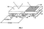
- FIG. 2is an isometric view depicting a portion of one embodiment of an interferometric modulator display array in which a movable reflective layer of a first interferometric modulator is in a released position and a movable reflective layer of a second interferometric modulator is in an actuated position.
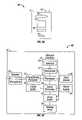
- FIG. 3Ais a system block diagram illustrating one embodiment of an electronic device incorporating a 3 ⁇ 3 interferometric modulator display array.
- FIG. 3Bis an illustration of an embodiment of a client of the server-based wireless network system of FIG. 1 .
- FIG. 3Cis an exemplary block diagram configuration of the client in FIG. 3B .
- FIG. 4Ais a diagram of movable mirror position versus applied voltage for one exemplary embodiment of an interferometric modulator of FIG. 2 .
- FIG. 4Bis an illustration of a set of row and column voltages that may be used to drive an interferometric modulator display array.
- FIGS. 5A and 5Billustrate one exemplary timing diagram for row and column signals that may be used to write a frame of data to the 3 ⁇ 3 interferometric modulator display array of FIG. 3A .
- FIG. 6Ais a cross section of the interferometric modulator of FIG. 2 .
- FIG. 6Bis a cross section of an alternative embodiment of an interferometric modulator.
- FIG. 6Cis a cross section of another alternative embodiment of an interferometric modulator.
- FIG. 7is a high level flowchart of a client control process.
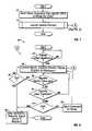
- FIG. 8is a flowchart of a client control process for launching and running a receive/display process.
- FIG. 9is a flowchart of a server control process for sending video data to a client.
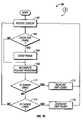
- FIG. 10is a flowchart of a frame skip count control process.
- a display array on a deviceincludes at least one driving circuit and an array of means, e.g., interferometric modulators, on which video data is displayed.
- Video datarefers to any kind of displayable data, including pictures, graphics, and words, displayable in either static or dynamic images (for example, a series of video frames that when viewed give the appearance of movement, e.g., a continuous ever-changing display of stock quotes, a “video clip”, or data indicating the occurrence of an event of action).
- Video dataas used herein, also refers to any kind of control data, including instructions on how the video data is to be processed (display mode), such as frame rate, and data format.
- the arrayis driven by the driving circuit to display video data.
- the driving circuitcan be programmed to receive video data and provide a subset of the received video data to the display array for display, where the subset provided is based on a particular refresh rate. For example, if the video data displayed changes relatively infrequently, not every frame of video data needs to be displayed to adequately convey the information in the video data. In some embodiments, every other frame can be displayed so that, for example, the display array, or a portion of the display array, is updated twice a second instead of four times per second.
- a “frame skip count”specifies a number of frames not to be displayed. The frame skip count can be programmed into the device, or it can be determined dynamically based on, for example, changes that occur in one or more portions of the video data during a time period.
- a methodprovides video data to an array having numerous interferometric modulators, where the video data is provided to different portions of the display array and each portion of the display array can be updated with its own refresh rate.
- One embodiment of this methodincludes receiving video data, determining a refresh rate for each of the one or more portions of an array of interferometric modulators based on one or more characteristics of the video data, and displaying the video data on the one or more portions of the array using the corresponding determined refresh rate.
- the inventionmay be implemented in any device that is configured to display an image, whether in motion (e.g., video) or stationary (e.g., still image), and whether textual or pictorial.
- the inventionmay be implemented in or associated with a variety of electronic devices such as, but not limited to, mobile telephones, wireless devices, personal data assistants (PDAs), hand-held or portable computers, GPS receivers/navigators, cameras, MP3 players, camcorders, game consoles, wrist watches, clocks, calculators, television monitors, flat panel displays, computer monitors, auto displays (e.g., odometer display, etc.), cockpit controls and/or displays, display of camera views (e.g., display of a rear view camera in a vehicle), electronic photographs, electronic billboards or signs, projectors, architectural structures, packaging, and aesthetic structures (e.g., display of images on a piece of jewelry).
- MEMS devices of similar structure to those described hereincan also be used in non-display applications such as in electronic switching devices.
- Transmissive liquid crystal display (LCD) modulatorsmodulate light by controlling the twist and/or alignment of crystalline materials to block or pass light.
- Reflective spatial light modulatorsexploit various physical effects to control the amount of light reflected to the imaging surface. Examples of such reflective modulators include reflective LCDs, and digital micromirror devices.
- Interferometric modulatorsare bi-stable display elements which employ a resonant optical cavity having at least one movable or deflectable wall. Constructive interference in the optical cavity determines the color of the viewable light emerging from the cavity. As the movable wall, typically comprised at least partially of metal, moves towards the stationary front surface of the cavity, the interference of light within the cavity is modulated, and that modulation affects the color of light emerging at the front surface of the modulator.
- the front surfaceis typically the surface where the image seen by the viewer appears, in the case where the interferometric modulator is a direct-view device.
- FIG. 1illustrates a networked system in accordance with one embodiment.
- a server 2such as a Web server is operatively coupled to a network 3 .
- the server 2can correspond to a Web server, to a cell-phone server, to a wireless e-mail server, and the like.
- the network 3can include wired networks, or wireless networks, such as WiFi networks, cell-phone networks, Bluetooth networks, and the like.
- the network 3can be operatively coupled to a broad variety of devices.
- devices that can be coupled to the network 3include a computer such as a laptop computer 4 , a personal digital assistant (PDA) 5 , which can include wireless handheld devices such as the BlackBerry, a Palm Pilot, a Pocket PC, and the like, and a cell phone 6 , such as a Web-enabled cell phone, Smartphone, and the like.
- PDApersonal digital assistant
- Many other devicescan be used, such as desk-top PCs, set-top boxes, digital media players, handheld PCs, Global Positioning System (GPS) navigation devices, automotive displays, or other stationary and mobile displays.
- GPSGlobal Positioning System
- FIG. 2One bi-stable display element embodiment comprising an interferometric MEMS display element is illustrated in FIG. 2 .
- the pixelsare in either a bright or dark state.
- the display elementIn the bright (“on” or “open”) state, the display element reflects a large portion of incident visible light to a user.
- the dark (“off” or “closed”) stateWhen in the dark (“off” or “closed”) state, the display element reflects little incident visible light to the user.
- the light reflectance properties of the “on” and “off” statesmay be reversed.
- MEMS pixelscan be configured to reflect predominantly at selected colors, allowing for a color display in addition to black and white.
- FIG. 2is an isometric view depicting two adjacent pixels in a series of pixels of a visual display array, wherein each pixel comprises a MEMS interferometric modulator.
- an interferometric modulator display arraycomprises a row/column array of these interferometric modulators.
- Each interferometric modulatorincludes a pair of reflective layers positioned at a variable and controllable distance from each other to form a resonant optical cavity with at least one variable dimension.
- one of the reflective layersmay be moved between two positions. In the first position, referred to herein as the released state, the movable layer is positioned at a relatively large distance from a fixed partially reflective layer.
- the movable layerIn the second position, the movable layer is positioned more closely adjacent to the partially reflective layer. Incident light that reflects from the two layers interferes constructively or destructively depending on the position of the movable reflective layer, producing either an overall reflective or non-reflective state for each pixel.
- the depicted portion of the pixel array in FIG. 2includes two adjacent interferometric modulators 12 a and 12 b .
- a movable and highly reflective layer 14 ais illustrated in a released position at a predetermined distance from a fixed partially reflective layer 16 a .
- the movable highly reflective layer 14 bis illustrated in an actuated position adjacent to the fixed partially reflective layer 16 b.
- the partially reflective layers 16 a , 16 bare electrically conductive, partially transparent and fixed, and may be fabricated, for example, by depositing one or more layers each of chromium and indium-tin-oxide onto a transparent substrate 20 .
- the layersare patterned into parallel strips, and may form row electrodes in a display device as described further below.
- the highly reflective layers 14 a , 14 bmay be formed as a series of parallel strips of a deposited metal layer or layers (orthogonal to the row electrodes, partially reflective layers 16 a , 16 b ) deposited on top of supports 18 and an intervening sacrificial material deposited between the supports 18 .
- the deformable metal layersare separated from the fixed metal layers by a defined air gap 19 .
- a highly conductive and reflective materialsuch as aluminum may be used for the deformable layers, and these strips may form column electrodes in a display device.
- the air gap 19remains between the layers 14 a , 16 a and the deformable layer is in a mechanically relaxed state as illustrated by the interferometric modulator 12 a in FIG. 2 .
- the capacitor formed at the intersection of the row and column electrodes at the corresponding pixelbecomes charged, and electrostatic forces pull the electrodes together.
- the movable layeris deformed and is forced against the fixed layer (a dielectric material which is not illustrated in this Figure may be deposited on the fixed layer to prevent shorting and control the separation distance) as illustrated by the interferometric modulator 12 b on the right in FIG. 2 .
- FIGS. 3 through 5illustrate an exemplary process and system for using an array of interferometric modulators in a display application.
- the process and systemcan also be applied to other displays, e.g., plasma, EL, OLED, STN LCD, and TFT LCD.
- interferometric modulators of the type described abovehave the ability to hold their state for a longer period of time without refresh, wherein the state of the interferometric modulators may be maintained in either of two states without refreshing, a display that uses interferometric modulators may be referred to as a bi-stable display.
- the state of the pixel elementsis maintained by applying a bias voltage, sometimes referred to as a latch voltage, to the one or more interferometric modulators that comprise the pixel element.
- a display devicetypically requires one or more controllers and driver circuits for proper control of the display device.
- Driver circuitssuch as those used to drive LCD's, for example, may be bonded directly to, and situated along the edge of the display panel itself. Alternatively, driver circuits may be mounted on flexible circuit elements connecting the display panel (at its edge) to the rest of an electronic system. In either case, the drivers are typically located at the interface of the display panel and the remainder of the electronic system.
- FIG. 3Ais a system block diagram illustrating some embodiments of an electronic device that can incorporate various aspects.
- the electronic deviceincludes a processor 21 which may be any general purpose single- or multi-chip microprocessor such as an ARM, Pentium®, Pentium II®, Pentium III®, Pentium IV®, Pentium® Pro, an 8051, a MIPS®, a Power PC®, an ALPHA®, or any special purpose microprocessor such as a digital signal processor, microcontroller, or a programmable gate array.
- the processor 21may be configured to execute one or more software modules.
- the processormay be configured to execute one or more software applications, including a web browser, a telephone application, an email program, or any other software application.
- FIG. 3Aillustrates an embodiment of electronic device that includes a network interface 27 connected to a processor 21 and, according to some embodiments, the network interface can be connected to an array driver 22 .
- the network interface 27includes the appropriate hardware and software so that the device can interact with another device over a network, for example, the server 2 shown in FIG. 1 .
- the processor 21is connected to driver controller 29 which is connected to an array driver 22 and to frame buffer 28 .
- the processor 21is also connected to the array driver 22 .
- the array driver 22is connected to and drives the display array 30 .
- the components illustrated in FIG. 3Aillustrate a configuration of an interferometric modulator display. However, this configuration can also be used in a LCD with an LCD controller and driver. As illustrated in FIG.
- the driver controller 29is connected to the processor 21 via a parallel bus 36 .
- a driver controller 29such as a LCD controller, is often associated with the system processor 21 , as a stand-alone Integrated Circuit (IC), such controllers may be implemented in many ways. They may be embedded in the processor 21 as hardware, embedded in the processor 21 as software, or fully integrated in hardware with the array driver 22 .
- the driver controller 29takes the display information generated by the processor 21 , reformats that information appropriately for high speed transmission to the display array 30 , and sends the formatted information to the array driver 22 .
- the array driver 22receives the formatted information from the driver controller 29 and reformats the video data into a parallel set of waveforms that are applied many times per second to the hundreds and sometimes thousands of leads coming from the display's x-y matrix of pixels.
- the currently available flat panel display controllers and driverssuch as those described immediately above have been designed to work almost exclusively with displays that need to be constantly refreshed. Because bi-stable displays (e.g., an array of interferometric modulators) do not require such constant refreshing, features that decrease power requirements may be realized through the use of bi-stable displays. However, if bi-stable displays are operated by the controllers and drivers that are used with current displays the advantages of a bi-stable display may not be optimized.
- bi-stable displayFor high speed bi-stable displays, such as the interferometric modulators described above, these improved controllers and drivers preferably implement low-refresh-rate modes, video rate refresh modes, and unique modes to facilitate the unique capabilities of bi-stable modulators. According to the methods and systems described herein, a bi-stable display may be configured to reduce power requirements in various manners.
- the array driver 22receives video data from the processor 21 via a data link 31 bypassing the driver controller 29 .
- the data link 31may comprise a serial peripheral interface (“SPI”), I 2 C bus, parallel bus, or any other available interface.
- the processor 21provides instructions to the array driver 22 that allow the array driver 22 to optimize the power requirements of the display array 30 (e.g., an interferometric modulator display).
- video data intended for a portion of the displaysuch as for example defined by the server 2
- the processor 21can route primitives, such as graphical primitives, along data link 31 to the array driver 22 . These graphical primitives can correspond to instructions such as primitives for drawing shapes and text.
- video datamay be provided from the network interface 27 to the array driver 22 via data link 33 .
- the network interface 27analyzes control information that is transmitted from the server 2 and determines whether the incoming video should be routed to either the processor 21 or, alternatively, the array driver 22 .
- video data provided by data link 33is not stored in the frame buffer 28 , as is usually the case in many embodiments.
- a second driver controller(not shown) can also be used to render video data for the array driver 22 .
- the data link 33may comprise a SPI, I 2 C bus, or any other available interface.
- the array driver 22can also include address decoding, row and column drivers for the display and the like.
- the network interface 27can also provide video data directly to the array driver 22 at least partially in response to instructions embedded within the video data provided to the network interface 27 . It will be understood by the skilled practitioner that arbiter logic can be used to control access by the network interface 27 and the processor 21 to prevent data collisions at the array driver 22 .
- a driver executing on the processor 21controls the timing of data transfer from the network interface 27 to the array driver 22 by permitting the data transfer during time intervals that are typically unused by the processor 21 , such as time intervals traditionally used for vertical blanking delays and/or horizontal blanking delays.
- this designpermits the server 2 to bypass the processor 21 and the driver controller 29 , and to directly address a portion of the display array 30 .
- thispermits the server 2 to directly address a predefined display array area of the display array 30 .
- the amount of data communicated between the network interface 27 and the array driver 22is relatively low and is communicated using a serial bus, such as an Inter-Integrated Circuit (I 2 C) bus or a Serial Peripheral Interface (SPI) bus.
- I 2 CInter-Integrated Circuit
- SPISerial Peripheral Interface
- the video data provided via data link 33can advantageously be displayed without a frame buffer 28 and with little or no intervention from the processor 21 .
- FIG. 3Aalso illustrates a configuration of a processor 21 coupled to a driver controller 29 , such as an interferometric modulator controller.
- the driver controller 29is coupled to the array driver 22 , which is connected to the display array 30 .
- the driver controller 29accounts for the display array 30 optimizations and provides information to the array driver 22 without the need for a separate connection between the array driver 22 and the processor 21 .
- the processor 21can be configured to communicate with a driver controller 29 , which can include a frame buffer 28 for temporary storage of one or more frames of video data.
- the array driver 22includes a row driver circuit 24 and a column driver circuit 26 that provide signals to a pixel display array 30 .
- the cross section of the array illustrated in FIG. 2is shown by the lines 1 - 1 in FIG. 3A .
- the row/column actuation protocolmay take advantage of a hysteresis property of these devices illustrated in FIG. 4A . It may require, for example, a 10 volt potential difference to cause a movable layer to deform from the released state to the actuated state. However, when the voltage is reduced from that value, the movable layer maintains its state as the voltage drops back below 10 volts.
- FIG. 4Athe row/column actuation protocol may take advantage of a hysteresis property of these devices illustrated in FIG. 4A . It may require, for example, a 10 volt potential difference to cause a movable layer to deform from the released state to the actuated state. However, when the voltage is reduced from that value, the
- the movable layerdoes not release completely until the voltage drops below 2 volts.
- the row/column actuation protocolcan be designed such that during row strobing, pixels in the strobed row that are to be actuated are exposed to a voltage difference of about 10 volts, and pixels that are to be released are exposed to a voltage difference of close to zero volts. After the strobe, the pixels are exposed to a steady state voltage difference of about 5 volts such that they remain in whatever state the row strobe put them in. After being written, each pixel sees a potential difference within the “stability window” of 3-7 volts in this example. This feature makes the pixel design illustrated in FIG.
- each pixel of the interferometric modulatoris essentially a capacitor formed by the fixed and moving reflective layers, this stable state can be held at a voltage within the hysteresis window with almost no power dissipation. Essentially no current flows into the pixel if the applied potential is fixed.
- a display framemay be created by asserting the set of column electrodes in accordance with the desired set of actuated pixels in the first row.
- a row pulseis then applied to the row 1 electrode, actuating the pixels corresponding to the asserted column lines.
- the asserted set of column electrodesis then changed to correspond to the desired set of actuated pixels in the second row.
- a pulseis then applied to the row 2 electrode, actuating the appropriate pixels in row 2 in accordance with the asserted column electrodes.
- the row 1 pixelsare unaffected by the row 2 pulse, and remain in the state they were set to during the row 1 pulse. This may be repeated for the entire series of rows in a sequential fashion to produce the frame.
- the framesare refreshed and/or updated with new video data by continually repeating this process at some desired number of frames per second.
- a wide variety of protocols for driving row and column electrodes of pixel arrays to produce display array framesare also well known and may be used.
- the exemplary client 40includes a housing 41 , a display 42 , an antenna 43 , a speaker 44 , an input device 48 , and a microphone 46 .
- the housing 41is generally formed from any of a variety of manufacturing processes as are well known to those of skill in the art, including injection molding, and vacuum forming.
- the housing 41may be made from any of a variety of materials, including but not limited to plastic, metal, glass, rubber, and ceramic, or a combination thereof.
- the housing 41includes removable portions (not shown) that may be interchanged with other removable portions of different color, or containing different logos, pictures, or symbols.
- the display 42 of exemplary client 40may be any of a variety of displays, including a bi-stable display, as described herein with respect to, for example, FIGS. 2 , 3 A, and 4 - 6 .
- the display 42includes a flat-panel display, such as plasma, EL, OLED, STN LCD, or TFT LCD as described above, or a non-flat-panel display, such as a CRT or other tube device, as is well known to those of skill in the art.
- the display 42includes an interferometric modulator display, as described herein.
- the components of one embodiment of exemplary client 40are schematically illustrated in FIG. 3C .
- the illustrated exemplary client 40includes a housing 41 and can include additional components at least partially enclosed therein.
- the client exemplary 40includes a network interface 27 that includes an antenna 43 which is coupled to a transceiver 47 .
- the transceiver 47is connected to a processor 21 , which is connected to conditioning hardware 52 .
- the conditioning hardware 52is connected to a speaker 44 and a microphone 46 .
- the processor 21is also connected to an input device 48 and a driver controller 29 .
- the driver controller 29is coupled to a frame buffer 28 , and to an array driver 22 , which in turn is coupled to a display array 30 .
- a power supply 50provides power to all components as required by the particular exemplary client 40 design.
- the network interface 27includes the antenna 43 , and the transceiver 47 so that the exemplary client 40 can communicate with another device over a network 3 , for example, the server 2 shown in FIG. 1 .
- the network interface 27may also have some processing capabilities to relieve requirements of the processor 21 .
- the antenna 43is any antenna known to those of skill in the art for transmitting and receiving signals.
- the antennatransmits and receives RF signals according to the IEEE 802.11 standard, including IEEE 802.11(a), (b), or (g).
- the antennatransmits and receives RF signals according to the BLUETOOTH standard.
- the antennais designed to receive CDMA, GSM, AMPS or other known signals that are used to communicate within a wireless cell phone network.
- the transceiver 47pre-processes the signals received from the antenna 43 so that they may be received by and further processed by the processor 21 .
- the transceiver 47also processes signals received from the processor 21 so that they may be transmitted from the exemplary client 40 via the antenna 43 .
- Processor 21generally controls the overall operation of the exemplary client 40 , although operational control may be shared with or given to the server 2 (not shown), as will be described in greater detail below.
- the processor 21includes a microcontroller, CPU, or logic unit to control operation of the exemplary client 40 .
- Conditioning hardware 52generally includes amplifiers and filters for transmitting signals to the speaker 44 , and for receiving signals from the microphone 46 .
- Conditioning hardware 52may be discrete components within the exemplary client 40 , or may be incorporated within the processor 21 or other components.
- the input device 48allows a user to control the operation of the exemplary client 40 .
- input device 48includes a keypad, such as a QWERTY keyboard or a telephone keypad, a button, a switch, a touch-sensitive screen, a pressure- or heat-sensitive membrane.
- a microphoneis an input device for the exemplary client 40 . When a microphone is used to input data to the device, voice commands may be provided by a user for controlling operations of the exemplary client 40 .
- driver controller 29is a conventional display controller or a bi-stable display controller (e.g., an interferometric modulator controller).
- array driver 22is a conventional driver or a bi-stable display driver (e.g., a interferometric modulator display).
- display array 30is a typical display array or a bi-stable display array (e.g., a display including an array of interferometric modulators).
- Power supply 50is any of a variety of energy storage devices as are well known in the art.
- power supply 50is a rechargeable battery, such as a nickel-cadmium battery or a lithium ion battery.
- power supply 50is a renewable energy source, a capacitor, or a solar cell, including a plastic solar cell, and solar-cell paint.
- power supply 50is configured to receive power from a wall outlet.
- the array driver 22contains a register that may be set to a predefined value to indicate that the input video stream is in an interlaced format and should be displayed on the bi-stable display in an interlaced format, without converting the video stream to a progressive scanned format. In this way the bi-stable display does not require interlace-to-progressive scan conversion of interlace video data.
- control programmabilityresides, as described above, in a display controller which can be located in several places in the electronic display system. In some cases control programmability resides in the array driver 22 located at the interface between the electronic display system and the display component itself. Those of skill in the art will recognize that the above-described optimization may be implemented in any number of hardware and/or software components and in various configurations.
- circuitryis embedded in the array driver 22 to take advantage of the fact that the output signal set of most graphics controllers includes a signal to delineate the horizontal active area of the display array 30 being addressed.
- This horizontal active areacan be changed via register settings in the driver controller 29 . These register settings can be changed by the processor 21 .
- This signalis usually designated as display enable (DE).
- Most all display video interfacesin addition utilize a line pulse (LP) or a horizontal synchronization (HSYNC) signal, which indicates the end of a line of data.
- LPline pulse
- HYNChorizontal synchronization
- a circuit which counts LPscan determine the vertical position of the current row.
- a driver controller 29is integrated with the array driver 22 .
- Such an embodimentis common in highly integrated systems such as cellular phones, watches, and other small area displays. Specialized circuitry within such an integrated array driver 22 first determines which pixels and hence rows require refresh, and only selects those rows that have pixels that have changed to update. With such circuitry, particular rows can be addressed in non-sequential order, on a changing basis depending on image content.
- This embodimenthas the advantage that since only the changed video data needs to be sent through the interface, data rates can be reduced between the processor 21 and the display array 30 . Lowering the effective data rate required between processor 21 and array driver 22 improves power consumption, noise immunity and electromagnetic interference issues for the system.
- FIGS. 4 and 5illustrate one possible actuation protocol for creating a display frame on the 3 ⁇ 3 array of FIG. 3 .
- FIG. 4Billustrates a possible set of column and row voltage levels that may be used for pixels exhibiting the hysteresis curves of FIG. 4A .
- actuating a pixelmay involve setting the appropriate column to ⁇ V bias , and the appropriate row to + ⁇ V, which may correspond to ⁇ 5 volts and +5 volts respectively.
- Releasing the pixelmay be accomplished by setting the appropriate column to +V bias , and the appropriate row to the same + ⁇ V, producing a zero volt potential difference across the pixel.
- actuating a pixelmay involve setting the appropriate column to +V bias , and the appropriate row to ⁇ V, which may correspond to 5 volts and ⁇ 5 volts respectively. Releasing the pixel may be accomplished by setting the appropriate column to ⁇ V bias , and the appropriate row to the same ⁇ V, producing a zero volt potential difference across the pixel. In those rows where the row voltage is held at zero volts, the pixels are stable in whatever state they were originally in, regardless of whether the column is at +V bias , or ⁇ V bias .
- FIG. 5Bis a timing diagram showing a series of row and column signals applied to the 3 ⁇ 3 array of FIG. 3A which will result in the display arrangement illustrated in FIG. 5A , where actuated pixels are non-reflective.
- the pixelsPrior to writing the frame illustrated in FIG. 5A , the pixels can be in any state, and in this example, all the rows are at 0 volts, and all the columns are at +5 volts. With these applied voltages, all pixels are stable in their existing actuated or released states.
- pixels ( 1 , 1 ), ( 1 , 2 ), ( 2 , 2 ), ( 3 , 2 ) and ( 3 , 3 )are actuated.
- columns 1 and 2are set to ⁇ 5 volts
- column 3is set to +5 volts. This does not change the state of any pixels, because all the pixels remain in the 3-7 volt stability window.
- Row 1is then strobed with a pulse that goes from 0, up to 5 volts, and back to zero. This actuates the ( 1 , 1 ) and ( 1 , 2 ) pixels and releases the ( 1 , 3 ) pixel. No other pixels in the array are affected.
- row 2is set to ⁇ 5 volts, and columns 1 and 3 are set to +5 volts.
- the same strobe applied to row 2will then actuate pixel ( 2 , 2 ) and release pixels ( 2 , 1 ) and ( 2 , 3 ). Again, no other pixels of the array are affected.
- Row 3is similarly set by setting columns 2 and 3 to ⁇ 5 volts, and column 1 to +5 volts.
- the row 3strobe sets the row 3 pixels as shown in FIG. 5A . After writing the frame, the row potentials are zero, and the column potentials can remain at either +5 or ⁇ 5 volts, and the display is then stable in the arrangement of FIG. 5A .
- FIGS. 6A-6Cillustrate three different embodiments of the moving mirror structure.
- FIG. 6Ais a cross section of the embodiment of FIG. 2 , where a strip of reflective material 14 is deposited on orthogonal supports 18 .
- FIG. 6Bthe reflective material 14 is attached to supports 18 at the corners only, on tethers 32 .
- FIG. 6Cthe reflective material 14 is suspended from a deformable layer 34 .
- This embodimenthas benefits because the structural design and materials used for the reflective material 14 can be optimized with respect to the optical properties, and the structural design and materials used for the deformable layer 34 can be optimized with respect to desired mechanical properties.
- FIG. 7shows a high-level flowchart of a client device 7 control process.
- This flowchartdescribes the process used by a client device 7 , such as a laptop computer 4 , a PDA 5 , or a cell phone 6 , connected to a network 3 , to graphically display video data, received from a server 2 via the network 3 .
- states of FIG. 7can be removed, added, or rearranged.
- the client device 7sends a signal to the server 2 via the network 3 that indicates the client device 7 is ready for video.
- a usermay start the process of FIG. 7 by turning on an electronic device such as a cell phone.
- the client device 7launches its control process. An example of launching a control process is discussed further with reference to FIG. 8 .
- FIG. 8shows a flowchart of a client device 7 control process for launching and running a control process. This flowchart illustrates in further detail state 76 discussed with reference to FIG. 7 . Depending on the embodiment, states of FIG. 8 can be removed, added, or rearranged.
- the client device 7makes a determination whether an action at the client device 7 requires an application at the client device 7 to be started, or whether the server 2 has transmitted an application to the client device 7 for execution, or whether the server 2 has transmitted to the client device 7 a request to execute an application resident at the client device 7 . If there is no need to launch an application the client device 7 remains at decision state 84 .
- the client device 7launches a process by which the client device 7 receives and displays video data.
- the video datamay stream from the server 2 , or may be downloaded to the client device 7 memory for later access.
- the video datacan be video, or a still image, or textual or pictorial information.
- the video datacan also have various compression encodings, and be interlaced or progressively scanned, and have various and varying refresh rates.
- the display array 30may be segmented into regions of arbitrary shape and size, each region receiving video data with characteristics, such as refresh rate or compression encoding, specific only to that region.
- the regionsmay change video data characteristics and shape and size.
- the regionsmay be opened and closed and re-opened.
- the client device 7can also receive control data.
- the control datacan comprise commands from the server 2 to the client device 7 regarding, for example, video data characteristics such as compression encoding, refresh rate, and interlaced or progressively scanned video data.
- the control datamay contain control instructions for segmentation of display array 30 , as well as differing instructions for different regions of display array 30 .
- the server 2sends control and video data to a PDA via a wireless network 3 to produce a continuously updating clock in the upper right corner of the display array 30 , a picture slideshow in the upper left corner of the display array 30 , a periodically updating score of a ball game along a lower region of the display array 30 , and a cloud shaped bubble reminder to buy bread continuously scrolling across the entire display array 30 .
- the video data for the photo slideshoware downloaded and reside in the PDA memory, and they are in an interlaced format.
- the clock and the ball game video datastream text from the server 2 .
- the reminderis text with a graphic and is in a progressively scanned format. It is appreciated that here presented is only an exemplary embodiment. Other embodiments are possible and are encompassed by state 86 and fall within the scope of this discussion.
- the client device 7looks for a command from the server 2 , such as a command to relocate a region of the display array 30 , a command to change the refresh rate for a region of the display array 30 , or a command to quit.
- a command from the server 2Upon receiving a command from the server 2 , the client device 7 proceeds to decision state 90 , and determines whether or not the command received while at decision state 88 is a command to quit. If, while at decision state 90 , the command received while at decision state 88 is determined to be a command to quit, the client device 7 continues to state 98 , and stops execution of the application and resets.
- the client device 7may also communicate status or other information to the server 2 , and/or may receive such similar communications from the server 2 .
- the client device 7proceeds back to state 86 . If, while at decision state 88 , a command from the server 2 is not received, the client device 7 advances to decision state 92 , at which the client device 7 looks for a command from the user, such as a command to stop updating a region of the display array 30 , or a command to quit. If, while at decision state 92 , the client device 7 receives no command from the user, the client device 7 returns to decision state 88 .
- the client device 7proceeds to decision state 94 , at which the client device 7 determines whether or not the command received in decision state 92 is a command to quit. If, while at decision state 94 , the command from the user received while at decision state 92 is not a command to quit, the client device 7 proceeds from decision state 94 to state 96 . At state 96 the client device 7 sends to the server 2 the user command received while at state 92 , such as a command to stop updating a region of the display array 30 , after which it returns to decision state 88 .
- the client device 7continues to state 98 , and stops execution of the application.
- the client device 7may also communicate status or other information to the server 2 , and/or may receive such similar communications from the server 2 .
- FIG. 9illustrates a control process by which the server 2 sends video data to the client device 7 .
- the server 2sends control information and video data to the client device 7 for display.
- states of FIG. 9can be removed, added, or rearranged.
- the server 2in embodiment (1), waits for a data request via the network 3 from the client device 7 , and alternatively, in embodiment (2) the server 2 sends video data without waiting for a data request from the client device 7 .
- the two embodimentsencompass scenarios in which either the server 2 or the client device 7 may initiate requests for video data to be sent from the server 2 to the client device 7 .
- the server 2continues to decision state 128 , at which a determination is made as to whether or not a response from the client device 7 has been received indicating that the client device 7 is ready (ready indication signal). If, while at state 128 , a ready indication signal is not received, the server 2 remains at decision state 128 until a ready indication signal is received.
- the server 2proceeds to state 126 , at which the server 2 sends control data to the client device 7 .
- the control datamay stream from the server 2 , or may be downloaded to the client device 7 memory for later access.
- the control datamay segment the display array 30 into regions of arbitrary shape and size, and may define video data characteristics, such as refresh rate or interlaced format for a particular region or all regions.
- the control datamay cause the regions to be opened or closed or re-opened.
- the server 2sends video data.
- the video datamay stream from the server 2 , or may be downloaded to the client device 7 memory for later access.
- the video datacan include motion images, or still images, textual or pictorial images.
- the video datacan also have various compression encodings, and be interlaced or progressively scanned, and have various and varying refresh rates. Each region may receive video data with characteristics, such as refresh rate or compression encoding, specific only to that region.
- the server 2proceeds to decision state 132 , at which the server 2 looks for a command from the user, such as a command to stop updating a region of the display array 30 , to increase the refresh rate, or a command to quit. If, while at decision state 132 , the server 2 receives a command from the user, the server 2 advances to state 134 . At state 134 the server 2 executes the command received from the user at state 132 , and then proceeds to decision state 138 . If, while at decision state 132 , the server 2 receives no command from the user, the server 2 advances to decision state 138 .
- a command from the usersuch as a command to stop updating a region of the display array 30 , to increase the refresh rate, or a command to quit.
- the server 2determines whether or not action by the client device 7 is needed, such as an action to receive and store video data to be displayed later, to increase the data transfer rate, or to expect the next set of video data to be in interlaced format. If, while at decision state 138 , the server 2 determines that an action by the client is needed, the server 2 advances to state 140 , at which the server 2 sends a command to the client device 7 to take the action, after which the server 2 then proceeds to state 130 . If, while at decision state 138 , the server 2 determines that an action by the client is not needed, the server 2 advances to decision state 142 .
- the server 2determines whether or not to end data transfer. If, while at decision state 142 , the server 2 determines to not end data transfer, server 2 returns to state 130 . If, while at decision state 142 , the server 2 determines to end data transfer, server 2 proceeds to state 144 , at which the server 2 ends data transfer, and sends a quit message to the client. The server 2 may also communicate status or other information to the client device 7 , and/or may receive such similar communications from the client device 7 .
- bi-stable displaysas do most flat panel displays, consume most of their power during frame update, it is desirable to be able to control how often a bi-stable display is updated in order to conserve power. For example, if there is very little change between adjacent frames of a video stream, the display array may be refreshed less frequently with little or no loss in image quality. As an example, image quality of typical PC desktop applications, displayed on an interferometric modulator display, would not suffer from a decreased refresh rate, since the interferometric modulator display is not susceptible to the flicker that would result from decreasing the refresh rate of most other displays. Thus, during operation of certain applications, the PC display system may reduce the refresh rate of bi-stable display elements, such as interferometric modulators, with minimal effect on the output of the display.
- the display devicemay reduce power requirements by reducing the refresh rate. While reduction of the refresh rate is not possible on a typical display, such as an LCD, a bi-stable display, such as an interferometric modulator display, can maintain the state of the pixel element for a longer period of time and, thus, may reduce the refresh rate when necessary.
- a bi-stable display devicewhen a bi-stable display device is used, up to 3 refreshes per video frame may be removed without affecting the output display. More particularly, because both the on and off states of pixels in a bi-stable display may be maintained without refreshing the pixels, a frame of video data from the video stream need only be updated on the display device once, and then maintained until a new video frame is ready for display. Accordingly, a bi-stable display may reduce power requirements by refreshing each video frame only once.
- frames of a video streamare skipped, based on a programmable “frame skip count.”
- a display driversuch as array driver 22
- array driver 22is programmed to skip a number of refreshes that are available to the bi-stable display, the interferometric modulator display array 30 .
- a register in the array driver 22stores a value, such as 0, 1, 2, 3, 4, etc, that represents a frame skip count. The driver may then access this register in order to determine the frequency of refreshing the display array 30 .
- the values 0, 1, 2, 3, 4, and 5may indicate that the driver updates the display array 30 every frame, every other frame, every third frame, every fourth frame, every fifth frame, and every sixth frame respectively.
- this registeris programmable through a communication bus (of either parallel or serial type) or a direct serial link, such as via a SPI.
- the registeris programmable from a direct connection with a controller, such as the driver controller 29 .
- the register programming informationcan be embedded within the data transmission stream at the controller and extracted from that stream at the driver.
- FIG. 10is a flowchart of a frame skip count control process of a client device 7 , illustrating a process 86 for determining the frame skip count of a sequence of video data frames.
- This process 86can be entered as the “launch/modify content receive/display as necessary” process state 86 show in FIG. 8 .
- states of FIG. 10can be removed, added, or rearranged.
- a client device 7receives video data from a server 2 , where the video data can include one or more frames of video data.
- the server 2 and the client device 7can be a variety of devices, for example, a server 2 and the client device 7 as shown in FIG. 1 and discussed hereinabove, or another type of server 2 and client device 7 .
- the processprocesses a frame of video data and determines whether or not to show the frame.
- the determination of whether or not to show the framecan use a pre-programmed frame skip count, a user specified frame skip count, or a frame skip count that can be dynamically determined during processing. If the frame skip count is such that the frame should be shown, in state 166 the process displays the frame and then continues to the next state 168 . If the frame skip count is such that the frame should be skipped, the process 86 does not show the frame, and the process 86 continues to state 168 .
- a rolling histogramis computed using the content from one or more of the previously received frames.
- the histogrammay be computed, for example, at the server 2 or at the client device 7 , in the processor 21 , or in the driver controller 29 .
- the processor 21can be configured to communicate histogram computations via the data link 31 or through data embedded in the high speed data stream.
- the process 86continues to state 170 where a determination is made regarding an adjustment to the frame skip count to be increased.
- the currently processed frameis compared to the resulting rolling histogram and analyzed to determine if the frame depicts change indicating that the frame skip count should be adjusted.
- the frame skip countcan be determined, for example, at the server 2 or at the client device 7 , in the processor 21 , or in the driver controller 29 . If the change in the video content is small, the process 86 continues to state 172 , and the frame skip count is increased so that frames are displayed less frequently.
- the processor 21can be configured to change the frame skip count and communicate the new frame skip count via the data link 31 or through data embedded in the high speed data stream.
- the processor 21 or the driver controller 29may adjust the frame skip count based partly on a user selected video quality and the then-current video characteristics.
- the change between the current frame and the rolling histogramcan be computed and compared to a predetermined threshold value to determine if the frame skip count should be changed.
- the process 86continues back to state 162 where it receives more content. If the change is not slow, the process 86 continues to state 174 where a determination is made regarding an adjustment to the frame skip count to be decreased. Processes and methods used in state 170 may analogously be used in state 174 to determine if the frame skip count is too high.
- the process 86continues to state 176 where the frame skip count is decreased so that frames are displayed more frequently. Processes and methods used in state 172 may analogously be used in state 176 to adjust the frame skip count. The process 86 continues to state 162 to receive more video content. If the change does not meet the threshold indicating the change in content is too large, the process 86 does not change the frame skip count and continues to state 162 to receive more video content.
Landscapes
- Engineering & Computer Science (AREA)
- Physics & Mathematics (AREA)
- General Physics & Mathematics (AREA)
- Computer Hardware Design (AREA)
- Theoretical Computer Science (AREA)
- Crystallography & Structural Chemistry (AREA)
- Chemical & Material Sciences (AREA)
- Nonlinear Science (AREA)
- Optics & Photonics (AREA)
- Control Of Indicators Other Than Cathode Ray Tubes (AREA)
- Mechanical Light Control Or Optical Switches (AREA)
- Liquid Crystal Display Device Control (AREA)
- Micromachines (AREA)
- Control Of El Displays (AREA)
Abstract
Description
Claims (17)
Priority Applications (39)
| Application Number | Priority Date | Filing Date | Title |
|---|---|---|---|
| US11/097,819US7679627B2 (en) | 2004-09-27 | 2005-04-01 | Controller and driver features for bi-stable display |
| IL169799AIL169799A0 (en) | 2004-09-27 | 2005-07-20 | Controller and driver features for bi-stable display |
| SG200906427-0ASG155987A1 (en) | 2004-09-27 | 2005-07-27 | Controller and driver features for bi-stable display |
| SG200504670ASG121049A1 (en) | 2004-09-27 | 2005-07-27 | Controller and driver features for bi-stable display |
| JP2005216693AJP4903404B2 (en) | 2004-09-27 | 2005-07-27 | Method and system for displaying data using bistable display element, method for manufacturing display system, and communication system for controlling display |
| AU2005203318AAU2005203318A1 (en) | 2004-09-27 | 2005-07-28 | Controller and driver features for bi-stable display |
| AU2005203339AAU2005203339A1 (en) | 2004-09-27 | 2005-07-29 | Controller and driver features for bi-stable display |
| CA002514680ACA2514680A1 (en) | 2004-09-27 | 2005-08-03 | Controller and driver features for bi-stable display |
| CA002514701ACA2514701A1 (en) | 2004-09-27 | 2005-08-03 | Controller and driver features for bi-stable display |
| JP2005226084AJP5059306B2 (en) | 2004-09-27 | 2005-08-04 | Controller and driver function for bi-stable display |
| SG200505134ASG121057A1 (en) | 2004-09-27 | 2005-08-11 | Controller and driver features for bi-stable display |
| TW102108103ATW201324498A (en) | 2004-09-27 | 2005-08-16 | Controller and driver features for bi-stable display |
| TW94127807ATWI397054B (en) | 2004-09-27 | 2005-08-16 | Controller and driver features for bi-stable display |
| TW104143448ATWI571855B (en) | 2004-09-27 | 2005-09-06 | Display and method, system, and server thereof |
| TW094130586ATWI417845B (en) | 2004-09-27 | 2005-09-06 | Display and method,system,and server thereof |
| TW102135414ATWI529685B (en) | 2004-09-27 | 2005-09-06 | Display and method, system, and server thereof |
| KR1020050085277AKR101233676B1 (en) | 2004-09-27 | 2005-09-13 | Controller and driver features for bi-stable display |
| EP13169789.8AEP2634767A3 (en) | 2004-09-27 | 2005-09-14 | Controller and driver features for bi-stable display |
| EP05255696AEP1640958A2 (en) | 2004-09-27 | 2005-09-14 | System with server based control of client device display features |
| MXPA05009865AMXPA05009865A (en) | 2004-09-27 | 2005-09-14 | Controller and driver features for bi-stable display. |
| EP05255652AEP1640951A3 (en) | 2004-09-27 | 2005-09-14 | Control of refresh rate for bi-stable display of e.g. a mobile phone |
| EP05255666AEP1640954A3 (en) | 2004-09-27 | 2005-09-14 | Controller and driver features for bi-stable display |
| TW094132520ATW200627954A (en) | 2004-09-27 | 2005-09-20 | System with server based control of client device display features |
| AU2005211601AAU2005211601A1 (en) | 2004-09-27 | 2005-09-20 | System with server based control of client device display features |
| CN2005101035583ACN1755435B (en) | 2004-09-27 | 2005-09-21 | Controller and driver features for bi-stable display |
| KR1020050087727AKR101147874B1 (en) | 2004-09-27 | 2005-09-21 | Controller and driver features for bi-stable display |
| CA002520624ACA2520624A1 (en) | 2004-09-27 | 2005-09-21 | System with server based control of client device display features |
| SG200506122ASG121170A1 (en) | 2004-09-27 | 2005-09-22 | System with server based control of client device display features |
| JP2005276325AJP2006163362A (en) | 2004-09-27 | 2005-09-22 | System with server based control of client device display features |
| RU2005129851/28ARU2005129851A (en) | 2004-09-27 | 2005-09-26 | CONTROLLER AND CONTROL DIAGRAM OF THE BISTABLE DISPLAY |
| MXPA05010305AMXPA05010305A (en) | 2004-09-27 | 2005-09-26 | System with server based control of client device display features. |
| BRPI0503906-1ABRPI0503906A (en) | 2004-09-27 | 2005-09-27 | controller and driver features for bistable display |
| BRPI0503909-6ABRPI0503909A (en) | 2004-09-27 | 2005-09-27 | server-based control system of client device display capabilities |
| KR1020050090150AKR20060092937A (en) | 2004-09-27 | 2005-09-27 | Server-based control of client device display configuration |
| HK06109565.0AHK1087517B (en) | 2004-09-27 | 2006-08-28 | Display system with bi-stable display elements, method of manufacturing the same, and display method |
| US12/499,003US20090267953A1 (en) | 2004-09-27 | 2009-07-07 | Controller and driver features for bi-stable display |
| US12/698,847US20100134503A1 (en) | 2004-09-27 | 2010-02-02 | Controller and driver features for bi-stable display |
| US13/896,715US20130249964A1 (en) | 2004-09-27 | 2013-05-17 | Controller and driver features for display |
| IN1855MU2014IN2014MU01855A (en) | 2004-09-27 | 2014-06-05 |
Applications Claiming Priority (2)
| Application Number | Priority Date | Filing Date | Title |
|---|---|---|---|
| US61341204P | 2004-09-27 | 2004-09-27 | |
| US11/097,819US7679627B2 (en) | 2004-09-27 | 2005-04-01 | Controller and driver features for bi-stable display |
Related Child Applications (1)
| Application Number | Title | Priority Date | Filing Date |
|---|---|---|---|
| US12/698,847DivisionUS20100134503A1 (en) | 2004-09-27 | 2010-02-02 | Controller and driver features for bi-stable display |
Publications (2)
| Publication Number | Publication Date |
|---|---|
| US20060077127A1 US20060077127A1 (en) | 2006-04-13 |
| US7679627B2true US7679627B2 (en) | 2010-03-16 |
Family
ID=35478679
Family Applications (4)
| Application Number | Title | Priority Date | Filing Date |
|---|---|---|---|
| US11/097,819Expired - Fee RelatedUS7679627B2 (en) | 2004-09-27 | 2005-04-01 | Controller and driver features for bi-stable display |
| US12/499,003AbandonedUS20090267953A1 (en) | 2004-09-27 | 2009-07-07 | Controller and driver features for bi-stable display |
| US12/698,847AbandonedUS20100134503A1 (en) | 2004-09-27 | 2010-02-02 | Controller and driver features for bi-stable display |
| US13/896,715AbandonedUS20130249964A1 (en) | 2004-09-27 | 2013-05-17 | Controller and driver features for display |
Family Applications After (3)
| Application Number | Title | Priority Date | Filing Date |
|---|---|---|---|
| US12/499,003AbandonedUS20090267953A1 (en) | 2004-09-27 | 2009-07-07 | Controller and driver features for bi-stable display |
| US12/698,847AbandonedUS20100134503A1 (en) | 2004-09-27 | 2010-02-02 | Controller and driver features for bi-stable display |
| US13/896,715AbandonedUS20130249964A1 (en) | 2004-09-27 | 2013-05-17 | Controller and driver features for display |
Country Status (12)
| Country | Link |
|---|---|
| US (4) | US7679627B2 (en) |
| EP (1) | EP1640951A3 (en) |
| JP (1) | JP5059306B2 (en) |
| KR (1) | KR101233676B1 (en) |
| CN (1) | CN1755435B (en) |
| AU (1) | AU2005203318A1 (en) |
| BR (1) | BRPI0503906A (en) |
| CA (1) | CA2514701A1 (en) |
| MX (1) | MXPA05009865A (en) |
| RU (1) | RU2005129851A (en) |
| SG (2) | SG121049A1 (en) |
| TW (3) | TWI571855B (en) |
Cited By (14)
| Publication number | Priority date | Publication date | Assignee | Title |
|---|---|---|---|---|
| US20090151771A1 (en)* | 2007-12-17 | 2009-06-18 | Qualcomm Mems Technologies, Inc. | Photovoltaics with interferometric ribbon masks |
| US20100134503A1 (en)* | 2004-09-27 | 2010-06-03 | Qualcomm Mems Technologies, Inc. | Controller and driver features for bi-stable display |
| US20100290102A1 (en)* | 2008-07-17 | 2010-11-18 | Qualcomm Mems Technologies, Inc. | Encapsulated electromechanical devices |
| US20110164027A1 (en)* | 2010-01-06 | 2011-07-07 | Qualcomm Mems Technologies, Inc. | Method of detecting change in display data |
| WO2011130718A2 (en) | 2010-04-16 | 2011-10-20 | Flex Lighting Ii, Llc | Front illumination device comprising a film-based lightguide |
| WO2011130715A2 (en) | 2010-04-16 | 2011-10-20 | Flex Lighting Ii, Llc | Illumination device comprising a film-based lightguide |
| US8736590B2 (en) | 2009-03-27 | 2014-05-27 | Qualcomm Mems Technologies, Inc. | Low voltage driver scheme for interferometric modulators |
| US8791897B2 (en) | 2004-09-27 | 2014-07-29 | Qualcomm Mems Technologies, Inc. | Method and system for writing data to MEMS display elements |
| US8928967B2 (en) | 1998-04-08 | 2015-01-06 | Qualcomm Mems Technologies, Inc. | Method and device for modulating light |
| US8970939B2 (en) | 2004-09-27 | 2015-03-03 | Qualcomm Mems Technologies, Inc. | Method and device for multistate interferometric light modulation |
| US8971675B2 (en) | 2006-01-13 | 2015-03-03 | Qualcomm Mems Technologies, Inc. | Interconnect structure for MEMS device |
| US9001412B2 (en) | 2004-09-27 | 2015-04-07 | Qualcomm Mems Technologies, Inc. | Electromechanical device with optical function separated from mechanical and electrical function |
| US9110289B2 (en) | 1998-04-08 | 2015-08-18 | Qualcomm Mems Technologies, Inc. | Device for modulating light with multiple electrodes |
| US10002588B2 (en) | 2015-03-20 | 2018-06-19 | Microsoft Technology Licensing, Llc | Electronic paper display device |
Families Citing this family (124)
| Publication number | Priority date | Publication date | Assignee | Title |
|---|---|---|---|---|
| US6674562B1 (en)* | 1994-05-05 | 2004-01-06 | Iridigm Display Corporation | Interferometric modulation of radiation |
| US7907319B2 (en)* | 1995-11-06 | 2011-03-15 | Qualcomm Mems Technologies, Inc. | Method and device for modulating light with optical compensation |
| US7471444B2 (en) | 1996-12-19 | 2008-12-30 | Idc, Llc | Interferometric modulation of radiation |
| WO2003007049A1 (en) | 1999-10-05 | 2003-01-23 | Iridigm Display Corporation | Photonic mems and structures |
| TWI289708B (en) | 2002-12-25 | 2007-11-11 | Qualcomm Mems Technologies Inc | Optical interference type color display |
| US20070009899A1 (en)* | 2003-10-02 | 2007-01-11 | Mounts William M | Nucleic acid arrays for detecting gene expression in animal models of inflammatory diseases |
| US7342705B2 (en) | 2004-02-03 | 2008-03-11 | Idc, Llc | Spatial light modulator with integrated optical compensation structure |
| US7855824B2 (en)* | 2004-03-06 | 2010-12-21 | Qualcomm Mems Technologies, Inc. | Method and system for color optimization in a display |
| US7499208B2 (en)* | 2004-08-27 | 2009-03-03 | Udc, Llc | Current mode display driver circuit realization feature |
| US7889163B2 (en) | 2004-08-27 | 2011-02-15 | Qualcomm Mems Technologies, Inc. | Drive method for MEMS devices |
| US7515147B2 (en) | 2004-08-27 | 2009-04-07 | Idc, Llc | Staggered column drive circuit systems and methods |
| US7551159B2 (en)* | 2004-08-27 | 2009-06-23 | Idc, Llc | System and method of sensing actuation and release voltages of an interferometric modulator |
| US7310179B2 (en)* | 2004-09-27 | 2007-12-18 | Idc, Llc | Method and device for selective adjustment of hysteresis window |
| US20060066557A1 (en)* | 2004-09-27 | 2006-03-30 | Floyd Philip D | Method and device for reflective display with time sequential color illumination |
| US7920135B2 (en)* | 2004-09-27 | 2011-04-05 | Qualcomm Mems Technologies, Inc. | Method and system for driving a bi-stable display |
| US7446927B2 (en) | 2004-09-27 | 2008-11-04 | Idc, Llc | MEMS switch with set and latch electrodes |
| AU2005289445A1 (en) | 2004-09-27 | 2006-04-06 | Idc, Llc | Method and device for multistate interferometric light modulation |
| US7626581B2 (en) | 2004-09-27 | 2009-12-01 | Idc, Llc | Device and method for display memory using manipulation of mechanical response |
| US7724993B2 (en) | 2004-09-27 | 2010-05-25 | Qualcomm Mems Technologies, Inc. | MEMS switches with deforming membranes |
| US7136213B2 (en) | 2004-09-27 | 2006-11-14 | Idc, Llc | Interferometric modulators having charge persistence |
| US7898521B2 (en)* | 2004-09-27 | 2011-03-01 | Qualcomm Mems Technologies, Inc. | Device and method for wavelength filtering |
| US8878825B2 (en) | 2004-09-27 | 2014-11-04 | Qualcomm Mems Technologies, Inc. | System and method for providing a variable refresh rate of an interferometric modulator display |
| US8031133B2 (en)* | 2004-09-27 | 2011-10-04 | Qualcomm Mems Technologies, Inc. | Method and device for manipulating color in a display |
| US8102407B2 (en)* | 2004-09-27 | 2012-01-24 | Qualcomm Mems Technologies, Inc. | Method and device for manipulating color in a display |
| US7545550B2 (en) | 2004-09-27 | 2009-06-09 | Idc, Llc | Systems and methods of actuating MEMS display elements |
| US7525730B2 (en)* | 2004-09-27 | 2009-04-28 | Idc, Llc | Method and device for generating white in an interferometric modulator display |
| US7911428B2 (en) | 2004-09-27 | 2011-03-22 | Qualcomm Mems Technologies, Inc. | Method and device for manipulating color in a display |
| US7843410B2 (en)* | 2004-09-27 | 2010-11-30 | Qualcomm Mems Technologies, Inc. | Method and device for electrically programmable display |
| US7532195B2 (en) | 2004-09-27 | 2009-05-12 | Idc, Llc | Method and system for reducing power consumption in a display |
| US7345805B2 (en) | 2004-09-27 | 2008-03-18 | Idc, Llc | Interferometric modulator array with integrated MEMS electrical switches |
| US7710632B2 (en) | 2004-09-27 | 2010-05-04 | Qualcomm Mems Technologies, Inc. | Display device having an array of spatial light modulators with integrated color filters |
| US7807488B2 (en)* | 2004-09-27 | 2010-10-05 | Qualcomm Mems Technologies, Inc. | Display element having filter material diffused in a substrate of the display element |
| US7928928B2 (en) | 2004-09-27 | 2011-04-19 | Qualcomm Mems Technologies, Inc. | Apparatus and method for reducing perceived color shift |
| US7675669B2 (en)* | 2004-09-27 | 2010-03-09 | Qualcomm Mems Technologies, Inc. | Method and system for driving interferometric modulators |
| US8362987B2 (en)* | 2004-09-27 | 2013-01-29 | Qualcomm Mems Technologies, Inc. | Method and device for manipulating color in a display |
| US7948457B2 (en) | 2005-05-05 | 2011-05-24 | Qualcomm Mems Technologies, Inc. | Systems and methods of actuating MEMS display elements |
| US7920136B2 (en) | 2005-05-05 | 2011-04-05 | Qualcomm Mems Technologies, Inc. | System and method of driving a MEMS display device |
| EP1878001A1 (en)* | 2005-05-05 | 2008-01-16 | QUALCOMM Incorporated, Inc. | Dynamic driver ic and display panel configuration |
| US7355779B2 (en) | 2005-09-02 | 2008-04-08 | Idc, Llc | Method and system for driving MEMS display elements |
| KR100720652B1 (en)* | 2005-09-08 | 2007-05-21 | 삼성전자주식회사 | Display drive circuit |
| US20070126673A1 (en)* | 2005-12-07 | 2007-06-07 | Kostadin Djordjev | Method and system for writing data to MEMS display elements |
| US8391630B2 (en) | 2005-12-22 | 2013-03-05 | Qualcomm Mems Technologies, Inc. | System and method for power reduction when decompressing video streams for interferometric modulator displays |
| US8194056B2 (en) | 2006-02-09 | 2012-06-05 | Qualcomm Mems Technologies Inc. | Method and system for writing data to MEMS display elements |
| US8004514B2 (en)* | 2006-02-10 | 2011-08-23 | Qualcomm Mems Technologies, Inc. | Method and system for updating of displays showing deterministic content |
| JP4550927B2 (en)* | 2006-03-28 | 2010-09-22 | パナソニック株式会社 | Navigation device |
| US7903047B2 (en) | 2006-04-17 | 2011-03-08 | Qualcomm Mems Technologies, Inc. | Mode indicator for interferometric modulator displays |
| US8004743B2 (en)* | 2006-04-21 | 2011-08-23 | Qualcomm Mems Technologies, Inc. | Method and apparatus for providing brightness control in an interferometric modulator (IMOD) display |
| US8049713B2 (en) | 2006-04-24 | 2011-11-01 | Qualcomm Mems Technologies, Inc. | Power consumption optimized display update |
| US8773494B2 (en) | 2006-08-29 | 2014-07-08 | Microsoft Corporation | Techniques for managing visual compositions for a multimedia conference call |
| US7742012B2 (en)* | 2006-09-14 | 2010-06-22 | Spring Design Co. Ltd. | Electronic devices having complementary dual displays |
| US7990338B2 (en)* | 2006-09-14 | 2011-08-02 | Spring Design Co., Ltd | Electronic devices having complementary dual displays |
| US7973738B2 (en)* | 2006-09-14 | 2011-07-05 | Spring Design Co. Ltd. | Electronic devices having complementary dual displays |
| US8629814B2 (en) | 2006-09-14 | 2014-01-14 | Quickbiz Holdings Limited | Controlling complementary bistable and refresh-based displays |
| US20080068292A1 (en)* | 2006-09-14 | 2008-03-20 | Springs Design, Inc. | Electronic devices having complementary dual displays |
| EP1943551A2 (en) | 2006-10-06 | 2008-07-16 | Qualcomm Mems Technologies, Inc. | Light guide |
| EP1943555B1 (en) | 2006-10-06 | 2012-05-02 | QUALCOMM MEMS Technologies, Inc. | Optical loss structure integrated in an illumination apparatus of a display |
| AU2007307684A1 (en)* | 2006-10-11 | 2008-04-17 | Quartex, Division Of Primex, Inc. | Traceable record generation system and method using wireless networks |
| US20080101410A1 (en)* | 2006-10-25 | 2008-05-01 | Microsoft Corporation | Techniques for managing output bandwidth for a conferencing server |
| US8451279B2 (en)* | 2006-12-13 | 2013-05-28 | Nvidia Corporation | System, method and computer program product for adjusting a refresh rate of a display |
| US8179388B2 (en)* | 2006-12-15 | 2012-05-15 | Nvidia Corporation | System, method and computer program product for adjusting a refresh rate of a display for power savings |
| US20080192029A1 (en)* | 2007-02-08 | 2008-08-14 | Michael Hugh Anderson | Passive circuits for de-multiplexing display inputs |
| JP5105922B2 (en)* | 2007-03-22 | 2012-12-26 | 日本電気株式会社 | Information update system, information storage server, information update method, and program |
| US7903107B2 (en) | 2007-06-18 | 2011-03-08 | Sony Ericsson Mobile Communications Ab | Adaptive refresh rate features |
| US7595926B2 (en)* | 2007-07-05 | 2009-09-29 | Qualcomm Mems Technologies, Inc. | Integrated IMODS and solar cells on a substrate |
| US7926072B2 (en) | 2007-10-01 | 2011-04-12 | Spring Design Co. Ltd. | Application programming interface for providing native and non-native display utility |
| US8207977B1 (en) | 2007-10-04 | 2012-06-26 | Nvidia Corporation | System, method, and computer program product for changing a refresh rate based on an identified hardware aspect of a display system |
| US8284210B1 (en) | 2007-10-04 | 2012-10-09 | Nvidia Corporation | Bandwidth-driven system, method, and computer program product for changing a refresh rate |
| JP5438021B2 (en)* | 2007-11-20 | 2014-03-12 | コーニンクレッカ フィリップス エヌ ヴェ | Power saving transparent display |
| US8068710B2 (en) | 2007-12-07 | 2011-11-29 | Qualcomm Mems Technologies, Inc. | Decoupled holographic film and diffuser |
| WO2009102617A2 (en)* | 2008-02-14 | 2009-08-20 | Qualcomm Mems Technologies, Inc. | Device having power generating black mask and method of fabricating the same |
| US8094358B2 (en)* | 2008-03-27 | 2012-01-10 | Qualcomm Mems Technologies, Inc. | Dimming mirror |
| US7660028B2 (en)* | 2008-03-28 | 2010-02-09 | Qualcomm Mems Technologies, Inc. | Apparatus and method of dual-mode display |
| US7787171B2 (en)* | 2008-03-31 | 2010-08-31 | Qualcomm Mems Technologies, Inc. | Human-readable, bi-state environmental sensors based on micro-mechanical membranes |
| US7787130B2 (en)* | 2008-03-31 | 2010-08-31 | Qualcomm Mems Technologies, Inc. | Human-readable, bi-state environmental sensors based on micro-mechanical membranes |
| US8077326B1 (en) | 2008-03-31 | 2011-12-13 | Qualcomm Mems Technologies, Inc. | Human-readable, bi-state environmental sensors based on micro-mechanical membranes |
| US7852491B2 (en)* | 2008-03-31 | 2010-12-14 | Qualcomm Mems Technologies, Inc. | Human-readable, bi-state environmental sensors based on micro-mechanical membranes |
| US7860668B2 (en)* | 2008-06-18 | 2010-12-28 | Qualcomm Mems Technologies, Inc. | Pressure measurement using a MEMS device |
| US8866698B2 (en)* | 2008-10-01 | 2014-10-21 | Pleiades Publishing Ltd. | Multi-display handheld device and supporting system |
| US20100157406A1 (en)* | 2008-12-19 | 2010-06-24 | Qualcomm Mems Technologies, Inc. | System and method for matching light source emission to display element reflectivity |
| US20100245370A1 (en)* | 2009-03-25 | 2010-09-30 | Qualcomm Mems Technologies, Inc. | Em shielding for display devices |
| US8867115B2 (en) | 2009-07-22 | 2014-10-21 | Dolby Laboratories Licensing Corporation | Control of array of two-dimensional imaging elements in light modulating displays |
| US8711361B2 (en)* | 2009-11-05 | 2014-04-29 | Qualcomm, Incorporated | Methods and devices for detecting and measuring environmental conditions in high performance device packages |
| JP5310529B2 (en)* | 2009-12-22 | 2013-10-09 | 株式会社豊田中央研究所 | Oscillator for plate member |
| US20110164068A1 (en)* | 2010-01-06 | 2011-07-07 | Qualcomm Mems Technologies, Inc. | Reordering display line updates |
| US20110176196A1 (en)* | 2010-01-15 | 2011-07-21 | Qualcomm Mems Technologies, Inc. | Methods and devices for pressure detection |
| US8593395B1 (en)* | 2010-02-23 | 2013-11-26 | Amazon Technologies, Inc. | Display response enhancement |
| US8848294B2 (en) | 2010-05-20 | 2014-09-30 | Qualcomm Mems Technologies, Inc. | Method and structure capable of changing color saturation |
| US8390916B2 (en) | 2010-06-29 | 2013-03-05 | Qualcomm Mems Technologies, Inc. | System and method for false-color sensing and display |
| US8904867B2 (en) | 2010-11-04 | 2014-12-09 | Qualcomm Mems Technologies, Inc. | Display-integrated optical accelerometer |
| US8714023B2 (en) | 2011-03-10 | 2014-05-06 | Qualcomm Mems Technologies, Inc. | System and method for detecting surface perturbations |
| US8988440B2 (en)* | 2011-03-15 | 2015-03-24 | Qualcomm Mems Technologies, Inc. | Inactive dummy pixels |
| US9176530B2 (en) | 2011-08-17 | 2015-11-03 | Apple Inc. | Bi-stable spring with flexible display |
| US20140043349A1 (en)* | 2012-08-08 | 2014-02-13 | Qualcomm Mems Technologies, Inc. | Display element change detection for selective line update |
| US9558721B2 (en)* | 2012-10-15 | 2017-01-31 | Apple Inc. | Content-based adaptive refresh schemes for low-power displays |
| TWI688850B (en) | 2013-08-13 | 2020-03-21 | 飛利斯有限公司 | Article with electronic display |
| WO2015031426A1 (en) | 2013-08-27 | 2015-03-05 | Polyera Corporation | Flexible display and detection of flex state |
| CN105793781B (en) | 2013-08-27 | 2019-11-05 | 飞利斯有限公司 | Attachable device with deflection electronic component |
| WO2015038684A1 (en) | 2013-09-10 | 2015-03-19 | Polyera Corporation | Attachable article with signaling, split display and messaging features |
| KR102104360B1 (en)* | 2013-11-20 | 2020-04-24 | 엘지디스플레이 주식회사 | Liquid crystal display device, appatus and method for driving the same |
| TWI676880B (en) | 2013-12-24 | 2019-11-11 | 美商飛利斯有限公司 | Dynamically flexible article |
| WO2015100224A1 (en) | 2013-12-24 | 2015-07-02 | Polyera Corporation | Flexible electronic display with user interface based on sensed movements |
| CN106030688B (en) | 2013-12-24 | 2020-01-24 | 飞利斯有限公司 | flexible electronics |
| JP6639400B2 (en) | 2013-12-24 | 2020-02-05 | フレックステラ, インコーポレイテッドFlexterra, Inc. | Support structure for attachable two-dimensional flexible electronic device |
| US20150227245A1 (en) | 2014-02-10 | 2015-08-13 | Polyera Corporation | Attachable Device with Flexible Electronic Display Orientation Detection |
| US10127273B2 (en) | 2014-04-15 | 2018-11-13 | Splunk Inc. | Distributed processing of network data using remote capture agents |
| US10693742B2 (en) | 2014-04-15 | 2020-06-23 | Splunk Inc. | Inline visualizations of metrics related to captured network data |
| US9762443B2 (en) | 2014-04-15 | 2017-09-12 | Splunk Inc. | Transformation of network data at remote capture agents |
| US9838512B2 (en) | 2014-10-30 | 2017-12-05 | Splunk Inc. | Protocol-based capture of network data using remote capture agents |
| US10523521B2 (en) | 2014-04-15 | 2019-12-31 | Splunk Inc. | Managing ephemeral event streams generated from captured network data |
| US10462004B2 (en) | 2014-04-15 | 2019-10-29 | Splunk Inc. | Visualizations of statistics associated with captured network data |
| US12028208B1 (en) | 2014-05-09 | 2024-07-02 | Splunk Inc. | Selective event stream data storage based on network traffic volume |
| WO2015175452A1 (en) | 2014-05-12 | 2015-11-19 | Polyera Corporation | High quality image updates in bi-stable displays |
| WO2015184045A2 (en) | 2014-05-28 | 2015-12-03 | Polyera Corporation | Device with flexible electronic components on multiple surfaces |
| US9596253B2 (en) | 2014-10-30 | 2017-03-14 | Splunk Inc. | Capture triggers for capturing network data |
| WO2016086100A1 (en)* | 2014-11-25 | 2016-06-02 | Arris Enterprises, Inc. | Filler detection during trickplay |
| WO2016138356A1 (en) | 2015-02-26 | 2016-09-01 | Polyera Corporation | Attachable device having a flexible electronic component |
| US10522108B2 (en)* | 2018-05-23 | 2019-12-31 | Qualcomm Incorporated | Optimized histogram reads for efficient display post processing and improved power gains |
| US11132957B2 (en)* | 2018-10-03 | 2021-09-28 | Mediatek Inc. | Method and apparatus for performing display control of an electronic device with aid of dynamic refresh-rate adjustment |
| CN112837641B (en)* | 2019-11-25 | 2023-09-12 | 敦泰电子股份有限公司 | Display low frame rate mode driving method |
| US20230135357A1 (en)* | 2020-03-16 | 2023-05-04 | Solchroma Technologies, Inc. | Driving waveforms for reflective displays and reflective displays using the same |
| DE102020207184B3 (en) | 2020-06-09 | 2021-07-29 | TechnoTeam Holding GmbH | Method for determining the start of relaxation after an image burn-in process on optical display devices that can be controlled pixel by pixel |
| TWI772099B (en)* | 2020-09-23 | 2022-07-21 | 瑞鼎科技股份有限公司 | Brightness compensation method applied to organic light-emitting diode display |
| CN116844491A (en)* | 2022-03-23 | 2023-10-03 | 群创光电股份有限公司 | display screen |
| WO2025019951A1 (en)* | 2023-07-26 | 2025-01-30 | Vuereal Inc. | Sectional driving |
Citations (300)
| Publication number | Priority date | Publication date | Assignee | Title |
|---|---|---|---|---|
| US3982239A (en) | 1973-02-07 | 1976-09-21 | North Hills Electronics, Inc. | Saturation drive arrangements for optically bistable displays |
| US4403248A (en) | 1980-03-04 | 1983-09-06 | U.S. Philips Corporation | Display device with deformable reflective medium |
| US4441791A (en) | 1980-09-02 | 1984-04-10 | Texas Instruments Incorporated | Deformable mirror light modulator |
| US4482213A (en) | 1982-11-23 | 1984-11-13 | Texas Instruments Incorporated | Perimeter seal reinforcement holes for plastic LCDs |
| US4500171A (en) | 1982-06-02 | 1985-02-19 | Texas Instruments Incorporated | Process for plastic LCD fill hole sealing |
| US4519676A (en) | 1982-02-01 | 1985-05-28 | U.S. Philips Corporation | Passive display device |
| US4566935A (en) | 1984-07-31 | 1986-01-28 | Texas Instruments Incorporated | Spatial light modulator and method |
| US4571603A (en) | 1981-11-03 | 1986-02-18 | Texas Instruments Incorporated | Deformable mirror electrostatic printer |
| US4596992A (en) | 1984-08-31 | 1986-06-24 | Texas Instruments Incorporated | Linear spatial light modulator and printer |
| US4615595A (en) | 1984-10-10 | 1986-10-07 | Texas Instruments Incorporated | Frame addressed spatial light modulator |
| US4662746A (en) | 1985-10-30 | 1987-05-05 | Texas Instruments Incorporated | Spatial light modulator and method |
| US4681403A (en) | 1981-07-16 | 1987-07-21 | U.S. Philips Corporation | Display device with micromechanical leaf spring switches |
| US4710732A (en) | 1984-07-31 | 1987-12-01 | Texas Instruments Incorporated | Spatial light modulator and method |
| US4709995A (en) | 1984-08-18 | 1987-12-01 | Canon Kabushiki Kaisha | Ferroelectric display panel and driving method therefor to achieve gray scale |
| EP0300754A2 (en) | 1987-07-21 | 1989-01-25 | THORN EMI plc | Display device |
| EP0306308A2 (en) | 1987-09-04 | 1989-03-08 | New York Institute Of Technology | Video display apparatus |
| US4856863A (en) | 1988-06-22 | 1989-08-15 | Texas Instruments Incorporated | Optical fiber interconnection network including spatial light modulator |
| US4859060A (en) | 1985-11-26 | 1989-08-22 | 501 Sharp Kabushiki Kaisha | Variable interferometric device and a process for the production of the same |
| US4954789A (en) | 1989-09-28 | 1990-09-04 | Texas Instruments Incorporated | Spatial light modulator |
| US4956619A (en) | 1988-02-19 | 1990-09-11 | Texas Instruments Incorporated | Spatial light modulator |
| US4982184A (en) | 1989-01-03 | 1991-01-01 | General Electric Company | Electrocrystallochromic display and element |
| US5018256A (en) | 1990-06-29 | 1991-05-28 | Texas Instruments Incorporated | Architecture and process for integrating DMD with control circuit substrates |
| US5028939A (en) | 1988-08-23 | 1991-07-02 | Texas Instruments Incorporated | Spatial light modulator system |
| US5034736A (en) | 1989-08-14 | 1991-07-23 | Polaroid Corporation | Bistable display with permuted excitation |
| US5037173A (en) | 1989-11-22 | 1991-08-06 | Texas Instruments Incorporated | Optical interconnection network |
| US5055833A (en) | 1986-10-17 | 1991-10-08 | Thomson Grand Public | Method for the control of an electro-optical matrix screen and control circuit |
| US5061049A (en) | 1984-08-31 | 1991-10-29 | Texas Instruments Incorporated | Spatial light modulator and method |
| US5078479A (en) | 1990-04-20 | 1992-01-07 | Centre Suisse D'electronique Et De Microtechnique Sa | Light modulation device with matrix addressing |
| US5079544A (en) | 1989-02-27 | 1992-01-07 | Texas Instruments Incorporated | Standard independent digitized video system |
| US5083857A (en) | 1990-06-29 | 1992-01-28 | Texas Instruments Incorporated | Multi-level deformable mirror device |
| US5096279A (en) | 1984-08-31 | 1992-03-17 | Texas Instruments Incorporated | Spatial light modulator and method |
| US5099353A (en) | 1990-06-29 | 1992-03-24 | Texas Instruments Incorporated | Architecture and process for integrating DMD with control circuit substrates |
| US5124834A (en) | 1989-11-16 | 1992-06-23 | General Electric Company | Transferrable, self-supporting pellicle for elastomer light valve displays and method for making the same |
| US5142405A (en) | 1990-06-29 | 1992-08-25 | Texas Instruments Incorporated | Bistable dmd addressing circuit and method |
| US5142414A (en) | 1991-04-22 | 1992-08-25 | Koehler Dale R | Electrically actuatable temporal tristimulus-color device |
| US5162787A (en) | 1989-02-27 | 1992-11-10 | Texas Instruments Incorporated | Apparatus and method for digitized video system utilizing a moving display surface |
| US5168406A (en) | 1991-07-31 | 1992-12-01 | Texas Instruments Incorporated | Color deformable mirror device and method for manufacture |
| US5170156A (en) | 1989-02-27 | 1992-12-08 | Texas Instruments Incorporated | Multi-frequency two dimensional display system |
| US5172262A (en) | 1985-10-30 | 1992-12-15 | Texas Instruments Incorporated | Spatial light modulator and method |
| US5179274A (en) | 1991-07-12 | 1993-01-12 | Texas Instruments Incorporated | Method for controlling operation of optical systems and devices |
| US5192946A (en) | 1989-02-27 | 1993-03-09 | Texas Instruments Incorporated | Digitized color video display system |
| US5192395A (en) | 1990-10-12 | 1993-03-09 | Texas Instruments Incorporated | Method of making a digital flexure beam accelerometer |
| US5206629A (en) | 1989-02-27 | 1993-04-27 | Texas Instruments Incorporated | Spatial light modulator and memory for digitized video display |
| US5212582A (en) | 1992-03-04 | 1993-05-18 | Texas Instruments Incorporated | Electrostatically controlled beam steering device and method |
| US5214419A (en) | 1989-02-27 | 1993-05-25 | Texas Instruments Incorporated | Planarized true three dimensional display |
| US5214420A (en) | 1989-02-27 | 1993-05-25 | Texas Instruments Incorporated | Spatial light modulator projection system with random polarity light |
| US5216537A (en) | 1990-06-29 | 1993-06-01 | Texas Instruments Incorporated | Architecture and process for integrating DMD with control circuit substrates |
| US5226099A (en) | 1991-04-26 | 1993-07-06 | Texas Instruments Incorporated | Digital micromirror shutter device |
| US5227900A (en) | 1990-03-20 | 1993-07-13 | Canon Kabushiki Kaisha | Method of driving ferroelectric liquid crystal element |
| US5231532A (en) | 1992-02-05 | 1993-07-27 | Texas Instruments Incorporated | Switchable resonant filter for optical radiation |
| US5233456A (en) | 1991-12-20 | 1993-08-03 | Texas Instruments Incorporated | Resonant mirror and method of manufacture |
| US5233459A (en) | 1991-03-06 | 1993-08-03 | Massachusetts Institute Of Technology | Electric display device |
| US5233385A (en) | 1991-12-18 | 1993-08-03 | Texas Instruments Incorporated | White light enhanced color field sequential projection |
| US5254980A (en) | 1991-09-06 | 1993-10-19 | Texas Instruments Incorporated | DMD display system controller |
| US5272473A (en) | 1989-02-27 | 1993-12-21 | Texas Instruments Incorporated | Reduced-speckle display system |
| US5278652A (en) | 1991-04-01 | 1994-01-11 | Texas Instruments Incorporated | DMD architecture and timing for use in a pulse width modulated display system |
| US5280277A (en) | 1990-06-29 | 1994-01-18 | Texas Instruments Incorporated | Field updated deformable mirror device |
| US5287215A (en) | 1991-07-17 | 1994-02-15 | Optron Systems, Inc. | Membrane light modulation systems |
| US5287096A (en) | 1989-02-27 | 1994-02-15 | Texas Instruments Incorporated | Variable luminosity display system |
| EP0583102A1 (en) | 1992-07-29 | 1994-02-16 | Canon Kabushiki Kaisha | Display control apparatus |
| US5296950A (en) | 1992-01-31 | 1994-03-22 | Texas Instruments Incorporated | Optical signal free-space conversion board |
| US5312513A (en) | 1992-04-03 | 1994-05-17 | Texas Instruments Incorporated | Methods of forming multiple phase light modulators |
| US5323002A (en) | 1992-03-25 | 1994-06-21 | Texas Instruments Incorporated | Spatial light modulator based optical calibration system |
| US5325116A (en) | 1992-09-18 | 1994-06-28 | Texas Instruments Incorporated | Device for writing to and reading from optical storage media |
| US5327286A (en) | 1992-08-31 | 1994-07-05 | Texas Instruments Incorporated | Real time optical correlation system |
| US5331454A (en) | 1990-11-13 | 1994-07-19 | Texas Instruments Incorporated | Low reset voltage process for DMD |
| EP0608056A1 (en) | 1993-01-11 | 1994-07-27 | Canon Kabushiki Kaisha | Display line dispatcher apparatus |
| US5365283A (en) | 1993-07-19 | 1994-11-15 | Texas Instruments Incorporated | Color phase control for projection display using spatial light modulator |
| US5396593A (en) | 1989-11-10 | 1995-03-07 | International Business Machines Corporation | Data processing apparatus |
| EP0655725A1 (en) | 1993-11-30 | 1995-05-31 | Rohm Co., Ltd. | Method and apparatus for reducing power consumption in a matrix display |
| EP0667548A1 (en) | 1994-01-27 | 1995-08-16 | AT&T Corp. | Micromechanical modulator |
| US5444566A (en) | 1994-03-07 | 1995-08-22 | Texas Instruments Incorporated | Optimized electronic operation of digital micromirror devices |
| US5446479A (en) | 1989-02-27 | 1995-08-29 | Texas Instruments Incorporated | Multi-dimensional array video processor system |
| US5448314A (en) | 1994-01-07 | 1995-09-05 | Texas Instruments | Method and apparatus for sequential color imaging |
| US5452024A (en) | 1993-11-01 | 1995-09-19 | Texas Instruments Incorporated | DMD display system |
| US5454906A (en) | 1994-06-21 | 1995-10-03 | Texas Instruments Inc. | Method of providing sacrificial spacer for micro-mechanical devices |
| US5457493A (en) | 1993-09-15 | 1995-10-10 | Texas Instruments Incorporated | Digital micro-mirror based image simulation system |
| US5457566A (en) | 1991-11-22 | 1995-10-10 | Texas Instruments Incorporated | DMD scanner |
| US5459602A (en) | 1993-10-29 | 1995-10-17 | Texas Instruments | Micro-mechanical optical shutter |
| US5461411A (en) | 1993-03-29 | 1995-10-24 | Texas Instruments Incorporated | Process and architecture for digital micromirror printer |
| US5483260A (en) | 1993-09-10 | 1996-01-09 | Dell Usa, L.P. | Method and apparatus for simplified video monitor control |
| US5488505A (en) | 1992-10-01 | 1996-01-30 | Engle; Craig D. | Enhanced electrostatic shutter mosaic modulator |
| US5489952A (en) | 1993-07-14 | 1996-02-06 | Texas Instruments Incorporated | Method and device for multi-format television |
| US5497172A (en) | 1994-06-13 | 1996-03-05 | Texas Instruments Incorporated | Pulse width modulation for spatial light modulator with split reset addressing |
| US5497197A (en) | 1993-11-04 | 1996-03-05 | Texas Instruments Incorporated | System and method for packaging data into video processor |
| US5499062A (en) | 1994-06-23 | 1996-03-12 | Texas Instruments Incorporated | Multiplexed memory timing with block reset and secondary memory |
| US5506597A (en) | 1989-02-27 | 1996-04-09 | Texas Instruments Incorporated | Apparatus and method for image projection |
| US5517347A (en) | 1993-12-01 | 1996-05-14 | Texas Instruments Incorporated | Direct view deformable mirror device |
| US5526172A (en) | 1993-07-27 | 1996-06-11 | Texas Instruments Incorporated | Microminiature, monolithic, variable electrical signal processor and apparatus including same |
| US5526051A (en) | 1993-10-27 | 1996-06-11 | Texas Instruments Incorporated | Digital television system |
| US5526688A (en) | 1990-10-12 | 1996-06-18 | Texas Instruments Incorporated | Digital flexure beam accelerometer and method |
| US5535047A (en) | 1995-04-18 | 1996-07-09 | Texas Instruments Incorporated | Active yoke hidden hinge digital micromirror device |
| EP0725380A1 (en) | 1995-01-31 | 1996-08-07 | Canon Kabushiki Kaisha | Display control method for display apparatus having maintainability of display-status function and display control system |
| US5548301A (en) | 1993-01-11 | 1996-08-20 | Texas Instruments Incorporated | Pixel control circuitry for spatial light modulator |
| US5552924A (en) | 1994-11-14 | 1996-09-03 | Texas Instruments Incorporated | Micromechanical device having an improved beam |
| US5552925A (en) | 1993-09-07 | 1996-09-03 | John M. Baker | Electro-micro-mechanical shutters on transparent substrates |
| US5563398A (en) | 1991-10-31 | 1996-10-08 | Texas Instruments Incorporated | Spatial light modulator scanning system |
| US5567334A (en) | 1995-02-27 | 1996-10-22 | Texas Instruments Incorporated | Method for creating a digital micromirror device using an aluminum hard mask |
| US5578976A (en) | 1995-06-22 | 1996-11-26 | Rockwell International Corporation | Micro electromechanical RF switch |
| US5581272A (en) | 1993-08-25 | 1996-12-03 | Texas Instruments Incorporated | Signal generator for controlling a spatial light modulator |
| US5583688A (en) | 1993-12-21 | 1996-12-10 | Texas Instruments Incorporated | Multi-level digital micromirror device |
| US5598565A (en) | 1993-12-29 | 1997-01-28 | Intel Corporation | Method and apparatus for screen power saving |
| US5597736A (en) | 1992-08-11 | 1997-01-28 | Texas Instruments Incorporated | High-yield spatial light modulator with light blocking layer |
| US5602671A (en) | 1990-11-13 | 1997-02-11 | Texas Instruments Incorporated | Low surface energy passivation layer for micromechanical devices |
| US5610625A (en) | 1992-05-20 | 1997-03-11 | Texas Instruments Incorporated | Monolithic spatial light modulator and memory package |
| US5610438A (en) | 1995-03-08 | 1997-03-11 | Texas Instruments Incorporated | Micro-mechanical device with non-evaporable getter |
| US5610624A (en) | 1994-11-30 | 1997-03-11 | Texas Instruments Incorporated | Spatial light modulator with reduced possibility of an on state defect |
| US5612713A (en) | 1995-01-06 | 1997-03-18 | Texas Instruments Incorporated | Digital micro-mirror device with block data loading |
| US5619366A (en) | 1992-06-08 | 1997-04-08 | Texas Instruments Incorporated | Controllable surface filter |
| US5619061A (en) | 1993-07-27 | 1997-04-08 | Texas Instruments Incorporated | Micromechanical microwave switching |
| US5629790A (en) | 1993-10-18 | 1997-05-13 | Neukermans; Armand P. | Micromachined torsional scanner |
| US5633652A (en) | 1984-02-17 | 1997-05-27 | Canon Kabushiki Kaisha | Method for driving optical modulation device |
| US5636052A (en) | 1994-07-29 | 1997-06-03 | Lucent Technologies Inc. | Direct view display based on a micromechanical modulation |
| US5638084A (en) | 1992-05-22 | 1997-06-10 | Dielectric Systems International, Inc. | Lighting-independent color video display |
| US5638946A (en) | 1996-01-11 | 1997-06-17 | Northeastern University | Micromechanical switch with insulated switch contact |
| US5646768A (en) | 1994-07-29 | 1997-07-08 | Texas Instruments Incorporated | Support posts for micro-mechanical devices |
| US5650881A (en) | 1994-11-02 | 1997-07-22 | Texas Instruments Incorporated | Support post architecture for micromechanical devices |
| US5654741A (en) | 1994-05-17 | 1997-08-05 | Texas Instruments Incorporation | Spatial light modulator display pointing device |
| US5659374A (en) | 1992-10-23 | 1997-08-19 | Texas Instruments Incorporated | Method of repairing defective pixels |
| US5665997A (en) | 1994-03-31 | 1997-09-09 | Texas Instruments Incorporated | Grated landing area to eliminate sticking of micro-mechanical devices |
| US5745281A (en) | 1995-12-29 | 1998-04-28 | Hewlett-Packard Company | Electrostatically-driven light modulator and display |
| US5754160A (en) | 1994-04-18 | 1998-05-19 | Casio Computer Co., Ltd. | Liquid crystal display device having a plurality of scanning methods |
| US5771116A (en) | 1996-10-21 | 1998-06-23 | Texas Instruments Incorporated | Multiple bias level reset waveform for enhanced DMD control |
| EP0852371A1 (en) | 1995-09-20 | 1998-07-08 | Hitachi, Ltd. | Image display device |
| US5808780A (en) | 1997-06-09 | 1998-09-15 | Texas Instruments Incorporated | Non-contacting micromechanical optical switch |
| US5835255A (en) | 1986-04-23 | 1998-11-10 | Etalon, Inc. | Visible spectrum modulator arrays |
| US5842088A (en) | 1994-06-17 | 1998-11-24 | Texas Instruments Incorporated | Method of calibrating a spatial light modulator printing system |
| US5867302A (en) | 1997-08-07 | 1999-02-02 | Sandia Corporation | Bistable microelectromechanical actuator |
| EP0911794A1 (en) | 1997-10-16 | 1999-04-28 | Sharp Kabushiki Kaisha | Display device and method of addressing the same with simultaneous addressing of groups of strobe electrodes and pairs of data electrodes in combination |
| US5912758A (en) | 1996-09-11 | 1999-06-15 | Texas Instruments Incorporated | Bipolar reset for spatial light modulators |
| US5929831A (en)* | 1992-05-19 | 1999-07-27 | Canon Kabushiki Kaisha | Display control apparatus and method |
| US5943158A (en) | 1998-05-05 | 1999-08-24 | Lucent Technologies Inc. | Micro-mechanical, anti-reflection, switched optical modulator array and fabrication method |
| US5966235A (en) | 1997-09-30 | 1999-10-12 | Lucent Technologies, Inc. | Micro-mechanical modulator having an improved membrane configuration |
| WO1999052006A3 (en) | 1998-04-08 | 1999-12-29 | Etalon Inc | Interferometric modulation of radiation |
| US6028690A (en) | 1997-11-26 | 2000-02-22 | Texas Instruments Incorporated | Reduced micromirror mirror gaps for improved contrast ratio |
| US6038056A (en) | 1997-05-08 | 2000-03-14 | Texas Instruments Incorporated | Spatial light modulator having improved contrast ratio |
| US6040937A (en) | 1994-05-05 | 2000-03-21 | Etalon, Inc. | Interferometric modulation |
| US6061075A (en) | 1992-01-23 | 2000-05-09 | Texas Instruments Incorporated | Non-systolic time delay and integration printing |
| US6099132A (en) | 1994-09-23 | 2000-08-08 | Texas Instruments Incorporated | Manufacture method for micromechanical devices |
| US6100872A (en) | 1993-05-25 | 2000-08-08 | Canon Kabushiki Kaisha | Display control method and apparatus |
| US6113239A (en) | 1998-09-04 | 2000-09-05 | Sharp Laboratories Of America, Inc. | Projection display system for reflective light valves |
| US6147790A (en) | 1998-06-02 | 2000-11-14 | Texas Instruments Incorporated | Spring-ring micromechanical device |
| US6160833A (en) | 1998-05-06 | 2000-12-12 | Xerox Corporation | Blue vertical cavity surface emitting laser |
| US6180428B1 (en) | 1997-12-12 | 2001-01-30 | Xerox Corporation | Monolithic scanning light emitting devices using micromachining |
| US6201633B1 (en) | 1999-06-07 | 2001-03-13 | Xerox Corporation | Micro-electromechanical based bistable color display sheets |
| US6232936B1 (en) | 1993-12-03 | 2001-05-15 | Texas Instruments Incorporated | DMD Architecture to improve horizontal resolution |
| US20010003487A1 (en) | 1996-11-05 | 2001-06-14 | Mark W. Miles | Visible spectrum modulator arrays |
| US6275326B1 (en) | 1999-09-21 | 2001-08-14 | Lucent Technologies Inc. | Control arrangement for microelectromechanical devices and systems |
| US6282010B1 (en) | 1998-05-14 | 2001-08-28 | Texas Instruments Incorporated | Anti-reflective coatings for spatial light modulators |
| US6295154B1 (en) | 1998-06-05 | 2001-09-25 | Texas Instruments Incorporated | Optical switching apparatus |
| US6304297B1 (en) | 1998-07-21 | 2001-10-16 | Ati Technologies, Inc. | Method and apparatus for manipulating display of update rate |
| US20010034075A1 (en) | 2000-02-08 | 2001-10-25 | Shigeru Onoya | Semiconductor device and method of driving semiconductor device |
| US20010043205A1 (en) | 2000-04-27 | 2001-11-22 | Xiao-Yang Huang | Graphic controller for active matrix addressed bistable reflective Cholesteric displays |
| US20010043171A1 (en) | 2000-02-24 | 2001-11-22 | Van Gorkom Gerardus Gegorius Petrus | Display device comprising a light guide |
| US6323982B1 (en) | 1998-05-22 | 2001-11-27 | Texas Instruments Incorporated | Yield superstructure for digital micromirror device |
| US20010046081A1 (en) | 2000-01-31 | 2001-11-29 | Naoyuki Hayashi | Sheet-like display, sphere-like resin body, and micro-capsule |
| JP2001331146A (en) | 2000-05-22 | 2001-11-30 | Nec Corp | Video display device and display method therefor |
| US6327071B1 (en) | 1998-10-16 | 2001-12-04 | Fuji Photo Film Co., Ltd. | Drive methods of array-type light modulation element and flat-panel display |
| US20010051014A1 (en) | 2000-03-24 | 2001-12-13 | Behrang Behin | Optical switch employing biased rotatable combdrive devices and methods |
| US20020000959A1 (en) | 1998-10-08 | 2002-01-03 | International Business Machines Corporation | Micromechanical displays and fabrication method |
| JP2002006818A (en) | 2000-06-23 | 2002-01-11 | Toshiba Corp | Image processing apparatus and method, and image display system |
| US20020005827A1 (en) | 2000-06-13 | 2002-01-17 | Fuji Xerox Co. Ltd. | Photo-addressable type recording display apparatus |
| US20020012159A1 (en) | 1999-12-30 | 2002-01-31 | Tew Claude E. | Analog pulse width modulation cell for digital micromechanical device |
| US20020015215A1 (en) | 1994-05-05 | 2002-02-07 | Iridigm Display Corporation, A Delaware Corporation | Interferometric modulation of radiation |
| US20020024711A1 (en) | 1994-05-05 | 2002-02-28 | Iridigm Display Corporation, A Delaware Corporation | Interferometric modulation of radiation |
| US6353435B2 (en)* | 1997-04-15 | 2002-03-05 | Hitachi, Ltd | Liquid crystal display control apparatus and liquid crystal display apparatus |
| US6356254B1 (en) | 1998-09-25 | 2002-03-12 | Fuji Photo Film Co., Ltd. | Array-type light modulating device and method of operating flat display unit |
| US6356085B1 (en) | 2000-05-09 | 2002-03-12 | Pacesetter, Inc. | Method and apparatus for converting capacitance to voltage |
| US20020036304A1 (en) | 1998-11-25 | 2002-03-28 | Raytheon Company, A Delaware Corporation | Method and apparatus for switching high frequency signals |
| US20020050882A1 (en) | 2000-10-27 | 2002-05-02 | Hyman Daniel J. | Microfabricated double-throw relay with multimorph actuator and electrostatic latch mechanism |
| US20020054424A1 (en) | 1994-05-05 | 2002-05-09 | Etalon, Inc. | Photonic mems and structures |
| US20020075226A1 (en) | 2000-12-19 | 2002-06-20 | Lippincott Louis A. | Obtaining a high refresh rate display using a low bandwidth digital interface |
| US20020093722A1 (en) | 2000-12-01 | 2002-07-18 | Edward Chan | Driver and method of operating a micro-electromechanical system device |
| US20020097133A1 (en) | 2000-12-27 | 2002-07-25 | Commissariat A L'energie Atomique | Micro-device with thermal actuator |
| US6429601B1 (en) | 1998-02-18 | 2002-08-06 | Cambridge Display Technology Ltd. | Electroluminescent devices |
| US6433917B1 (en) | 2000-11-22 | 2002-08-13 | Ball Semiconductor, Inc. | Light modulation device and system |
| EP1239448A2 (en) | 2001-03-10 | 2002-09-11 | Sharp Kabushiki Kaisha | Frame rate controller |
| JP2002287681A (en) | 2001-03-27 | 2002-10-04 | Mitsubishi Electric Corp | Partial hold type display control device and partial hold type display control method |
| US6465355B1 (en) | 2001-04-27 | 2002-10-15 | Hewlett-Packard Company | Method of fabricating suspended microstructures |
| US6473274B1 (en) | 2000-06-28 | 2002-10-29 | Texas Instruments Incorporated | Symmetrical microactuator structure for use in mass data storage devices, or the like |
| US6480177B2 (en) | 1997-06-04 | 2002-11-12 | Texas Instruments Incorporated | Blocked stepped address voltage for micromechanical devices |
| US20020179421A1 (en) | 2001-04-26 | 2002-12-05 | Williams Byron L. | Mechanically assisted restoring force support for micromachined membranes |
| US20020186108A1 (en) | 2001-04-02 | 2002-12-12 | Paul Hallbjorner | Micro electromechanical switches |
| US6496122B2 (en) | 1998-06-26 | 2002-12-17 | Sharp Laboratories Of America, Inc. | Image display and remote control system capable of displaying two distinct images |
| US20020190940A1 (en) | 1999-03-30 | 2002-12-19 | Kabushiki Kaisha Toshiba | Display apparatus |
| US6501107B1 (en) | 1998-12-02 | 2002-12-31 | Microsoft Corporation | Addressable fuse array for circuits and mechanical devices |
| US20030004272A1 (en) | 2000-03-01 | 2003-01-02 | Power Mark P J | Data transfer method and apparatus |
| US6507331B1 (en) | 1999-05-27 | 2003-01-14 | Koninklijke Philips Electronics N.V. | Display device |
| US6507330B1 (en) | 1999-09-01 | 2003-01-14 | Displaytech, Inc. | DC-balanced and non-DC-balanced drive schemes for liquid crystal devices |
| WO2003007049A1 (en) | 1999-10-05 | 2003-01-23 | Iridigm Display Corporation | Photonic mems and structures |
| EP1280129A2 (en) | 2001-07-27 | 2003-01-29 | Sharp Kabushiki Kaisha | Display device |
| WO2003015071A2 (en) | 2001-08-03 | 2003-02-20 | Sendo International Limited | Image refresh in a display |
| US6545335B1 (en) | 1999-12-27 | 2003-04-08 | Xerox Corporation | Structure and method for electrical isolation of optoelectronic integrated circuits |
| US6548908B2 (en) | 1999-12-27 | 2003-04-15 | Xerox Corporation | Structure and method for planar lateral oxidation in passive devices |
| US6549338B1 (en) | 1999-11-12 | 2003-04-15 | Texas Instruments Incorporated | Bandpass filter to reduce thermal impact of dichroic light shift |
| US6552840B2 (en) | 1999-12-03 | 2003-04-22 | Texas Instruments Incorporated | Electrostatic efficiency of micromechanical devices |
| WO2003044765A2 (en) | 2001-11-20 | 2003-05-30 | E Ink Corporation | Methods for driving bistable electro-optic displays |
| US6574033B1 (en) | 2002-02-27 | 2003-06-03 | Iridigm Display Corporation | Microelectromechanical systems device and method for fabricating same |
| US20030122773A1 (en) | 2001-12-18 | 2003-07-03 | Hajime Washio | Display device and driving method thereof |
| US6589625B1 (en) | 2001-08-01 | 2003-07-08 | Iridigm Display Corporation | Hermetic seal and method to create the same |
| US6593934B1 (en) | 2000-11-16 | 2003-07-15 | Industrial Technology Research Institute | Automatic gamma correction system for displays |
| US20030137521A1 (en) | 1999-04-30 | 2003-07-24 | E Ink Corporation | Methods for driving bistable electro-optic displays, and apparatus for use therein |
| US20030137215A1 (en) | 2002-01-24 | 2003-07-24 | Cabuz Eugen I. | Method and circuit for the control of large arrays of electrostatic actuators |
| US6600201B2 (en) | 2001-08-03 | 2003-07-29 | Hewlett-Packard Development Company, L.P. | Systems with high density packing of micromachines |
| US6606175B1 (en) | 1999-03-16 | 2003-08-12 | Sharp Laboratories Of America, Inc. | Multi-segment light-emitting diode |
| WO2003069413A1 (en) | 2002-02-12 | 2003-08-21 | Iridigm Display Corporation | A method for fabricating a structure for a microelectromechanical systems (mems) device |
| US6625047B2 (en) | 2000-12-31 | 2003-09-23 | Texas Instruments Incorporated | Micromechanical memory element |
| US6630786B2 (en) | 2001-03-30 | 2003-10-07 | Candescent Technologies Corporation | Light-emitting device having light-reflective layer formed with, or/and adjacent to, material that enhances device performance |
| US20030189536A1 (en) | 2000-03-14 | 2003-10-09 | Ruigt Adolphe Johannes Gerardus | Liquid crystal diplay device |
| US6632698B2 (en) | 2001-08-07 | 2003-10-14 | Hewlett-Packard Development Company, L.P. | Microelectromechanical device having a stiffened support beam, and methods of forming stiffened support beams in MEMS |
| US20030202266A1 (en) | 2002-04-30 | 2003-10-30 | Ring James W. | Micro-mirror device with light angle amplification |
| US20030202264A1 (en) | 2002-04-30 | 2003-10-30 | Weber Timothy L. | Micro-mirror device |
| US20030202265A1 (en) | 2002-04-30 | 2003-10-30 | Reboa Paul F. | Micro-mirror device including dielectrophoretic liquid |
| WO2003090199A1 (en) | 2002-04-19 | 2003-10-30 | Koninklijke Philips Electronics N.V. | Programmable drivers for display devices |
| US6643069B2 (en) | 2000-08-31 | 2003-11-04 | Texas Instruments Incorporated | SLM-base color projection display having multiple SLM's and multiple projection lenses |
| US6666561B1 (en) | 2002-10-28 | 2003-12-23 | Hewlett-Packard Development Company, L.P. | Continuously variable analog micro-mirror device |
| US6674090B1 (en) | 1999-12-27 | 2004-01-06 | Xerox Corporation | Structure and method for planar lateral oxidation in active |
| US20040008396A1 (en) | 2002-01-09 | 2004-01-15 | The Regents Of The University Of California | Differentially-driven MEMS spatial light modulator |
| WO2004006003A1 (en) | 2002-07-02 | 2004-01-15 | Iridigm Display Corporation | A device having a light-absorbing mask a method for fabricating same |
| JP2004032207A (en) | 2002-06-24 | 2004-01-29 | Seiko Epson Corp | Image display device, projector, program, and storage medium |
| US20040022044A1 (en) | 2001-01-30 | 2004-02-05 | Masazumi Yasuoka | Switch, integrated circuit device, and method of manufacturing switch |
| US20040027701A1 (en) | 2001-07-12 | 2004-02-12 | Hiroichi Ishikawa | Optical multilayer structure and its production method, optical switching device, and image display |
| JP2004088194A (en) | 2002-08-23 | 2004-03-18 | Seiko Epson Corp | Information processing apparatus, projector system and program |
| US20040051929A1 (en) | 1994-05-05 | 2004-03-18 | Sampsell Jeffrey Brian | Separable modulator |
| US6710908B2 (en) | 1994-05-05 | 2004-03-23 | Iridigm Display Corporation | Controlling micro-electro-mechanical cavities |
| US20040058532A1 (en) | 2002-09-20 | 2004-03-25 | Miles Mark W. | Controlling electromechanical behavior of structures within a microelectromechanical systems device |
| US20040080807A1 (en) | 2002-10-24 | 2004-04-29 | Zhizhang Chen | Mems-actuated color light modulator and methods |
| US6741503B1 (en) | 2002-12-04 | 2004-05-25 | Texas Instruments Incorporated | SLM display data address mapping for four bank frame buffer |
| US6741384B1 (en) | 2003-04-30 | 2004-05-25 | Hewlett-Packard Development Company, L.P. | Control of MEMS and light modulator arrays |
| JP2004151222A (en) | 2002-10-29 | 2004-05-27 | Sharp Corp | Liquid crystal display control device and liquid crystal display device |
| WO2004049034A1 (en) | 2002-11-22 | 2004-06-10 | Advanced Nano Systems | Mems scanning mirror with tunable natural frequency |
| US6762873B1 (en) | 1998-12-19 | 2004-07-13 | Qinetiq Limited | Methods of driving an array of optical elements |
| US20040145049A1 (en) | 2003-01-29 | 2004-07-29 | Mckinnell James C. | Micro-fabricated device with thermoelectric device and method of making |
| US20040147056A1 (en) | 2003-01-29 | 2004-07-29 | Mckinnell James C. | Micro-fabricated device and method of making |
| US6775174B2 (en) | 2000-12-28 | 2004-08-10 | Texas Instruments Incorporated | Memory architecture for micromirror cell |
| US6778155B2 (en) | 2000-07-31 | 2004-08-17 | Texas Instruments Incorporated | Display operation with inserted block clears |
| US20040160143A1 (en) | 2003-02-14 | 2004-08-19 | Shreeve Robert W. | Micro-mirror device with increased mirror tilt |
| US6781643B1 (en) | 1999-05-20 | 2004-08-24 | Nec Lcd Technologies, Ltd. | Active matrix liquid crystal display device |
| US6787384B2 (en) | 2001-08-17 | 2004-09-07 | Nec Corporation | Functional device, method of manufacturing therefor and driver circuit |
| US6787438B1 (en) | 2001-10-16 | 2004-09-07 | Teravieta Technologies, Inc. | Device having one or more contact structures interposed between a pair of electrodes |
| US6788520B1 (en) | 2000-04-10 | 2004-09-07 | Behrang Behin | Capacitive sensing scheme for digital control state detection in optical switches |
| US20040179281A1 (en) | 2003-03-12 | 2004-09-16 | Reboa Paul F. | Micro-mirror device including dielectrophoretic liquid |
| US20040212026A1 (en) | 2002-05-07 | 2004-10-28 | Hewlett-Packard Company | MEMS device having time-varying control |
| US6811267B1 (en) | 2003-06-09 | 2004-11-02 | Hewlett-Packard Development Company, L.P. | Display system with nonvisible data projection |
| US6813060B1 (en) | 2002-12-09 | 2004-11-02 | Sandia Corporation | Electrical latching of microelectromechanical devices |
| GB2401200A (en) | 2003-04-30 | 2004-11-03 | Hewlett Packard Development Co | Selective updating of a Micro-electromechanical system (MEMS) device |
| EP1473691A2 (en) | 2003-04-30 | 2004-11-03 | Hewlett-Packard Development Company, L.P. | Charge control of micro-electromechanical device |
| US20040218251A1 (en) | 2003-04-30 | 2004-11-04 | Arthur Piehl | Optical interference pixel display with charge control |
| US20040217378A1 (en) | 2003-04-30 | 2004-11-04 | Martin Eric T. | Charge control circuit for a micro-electromechanical device |
| US20040217919A1 (en) | 2003-04-30 | 2004-11-04 | Arthur Piehl | Self-packaged optical interference display device having anti-stiction bumps, integral micro-lens, and reflection-absorbing layers |
| US20040223204A1 (en) | 2003-05-09 | 2004-11-11 | Minyao Mao | Bistable latching actuator for optical switching applications |
| US6819469B1 (en) | 2003-05-05 | 2004-11-16 | Igor M. Koba | High-resolution spatial light modulator for 3-dimensional holographic display |
| US20040227493A1 (en) | 2003-04-30 | 2004-11-18 | Van Brocklin Andrew L. | System and a method of driving a parallel-plate variable micro-electromechanical capacitor |
| US6822628B2 (en) | 2001-06-28 | 2004-11-23 | Candescent Intellectual Property Services, Inc. | Methods and systems for compensating row-to-row brightness variations of a field emission display |
| US6825835B2 (en)* | 2000-11-24 | 2004-11-30 | Mitsubishi Denki Kabushiki Kaisha | Display device |
| US20040240138A1 (en) | 2003-05-14 | 2004-12-02 | Eric Martin | Charge control circuit |
| US20040246242A1 (en) | 2001-10-05 | 2004-12-09 | Daigo Sasaki | Display apparatus, image display system, and terminal using the same |
| US20040245588A1 (en) | 2003-06-03 | 2004-12-09 | Nikkel Eric L. | MEMS device and method of forming MEMS device |
| US20040263944A1 (en) | 2003-06-24 | 2004-12-30 | Miles Mark W. | Thin film precursor stack for MEMS manufacturing |
| US20050001797A1 (en) | 2003-07-02 | 2005-01-06 | Miller Nick M. | Multi-configuration display driver |
| US20050012577A1 (en) | 2002-05-07 | 2005-01-20 | Raytheon Company, A Delaware Corporation | Micro-electro-mechanical switch, and methods of making and using it |
| US6853129B1 (en) | 2000-07-28 | 2005-02-08 | Candescent Technologies Corporation | Protected substrate structure for a field emission display device |
| US6855610B2 (en) | 2002-09-18 | 2005-02-15 | Promos Technologies, Inc. | Method of forming self-aligned contact structure with locally etched gate conductive layer |
| US20050038950A1 (en) | 2003-08-13 | 2005-02-17 | Adelmann Todd C. | Storage device having a probe and a storage cell with moveable parts |
| US6859218B1 (en) | 2000-11-07 | 2005-02-22 | Hewlett-Packard Development Company, L.P. | Electronic display devices and methods |
| US6862029B1 (en) | 1999-07-27 | 2005-03-01 | Hewlett-Packard Development Company, L.P. | Color display system |
| US6862022B2 (en) | 2001-07-20 | 2005-03-01 | Hewlett-Packard Development Company, L.P. | Method and system for automatically selecting a vertical refresh rate for a video display monitor |
| US6861277B1 (en) | 2003-10-02 | 2005-03-01 | Hewlett-Packard Development Company, L.P. | Method of forming MEMS device |
| US20050057442A1 (en) | 2003-08-28 | 2005-03-17 | Olan Way | Adjacent display of sequential sub-images |
| US6870581B2 (en) | 2001-10-30 | 2005-03-22 | Sharp Laboratories Of America, Inc. | Single panel color video projection display using reflective banded color falling-raster illumination |
| US20050068583A1 (en) | 2003-09-30 | 2005-03-31 | Gutkowski Lawrence J. | Organizing a digital image |
| US20050069209A1 (en) | 2003-09-26 | 2005-03-31 | Niranjan Damera-Venkata | Generating and displaying spatially offset sub-frames |
| US20050116924A1 (en) | 2003-10-07 | 2005-06-02 | Rolltronics Corporation | Micro-electromechanical switching backplane |
| US6903860B2 (en) | 2003-11-01 | 2005-06-07 | Fusao Ishii | Vacuum packaged micromirror arrays and methods of manufacturing the same |
| US20050206991A1 (en) | 2003-12-09 | 2005-09-22 | Clarence Chui | System and method for addressing a MEMS display |
| US20050286114A1 (en) | 1996-12-19 | 2005-12-29 | Miles Mark W | Interferometric modulation of radiation |
| US20060017684A1 (en) | 2002-03-15 | 2006-01-26 | Koninklijke Phillips Electronics N.V. | Display driver and driving method reducing amount of data transferred to display driver |
| US20060044298A1 (en) | 2004-08-27 | 2006-03-02 | Marc Mignard | System and method of sensing actuation and release voltages of an interferometric modulator |
| US20060044246A1 (en) | 2004-08-27 | 2006-03-02 | Marc Mignard | Staggered column drive circuit systems and methods |
| US20060044928A1 (en) | 2004-08-27 | 2006-03-02 | Clarence Chui | Drive method for MEMS devices |
| US20060057754A1 (en) | 2004-08-27 | 2006-03-16 | Cummings William J | Systems and methods of actuating MEMS display elements |
| US20060056000A1 (en) | 2004-08-27 | 2006-03-16 | Marc Mignard | Current mode display driver circuit realization feature |
| US20060066560A1 (en) | 2004-09-27 | 2006-03-30 | Gally Brian J | Systems and methods of actuating MEMS display elements |
| US20060066542A1 (en) | 2004-09-27 | 2006-03-30 | Clarence Chui | Interferometric modulators having charge persistence |
| US20060066937A1 (en) | 2004-09-27 | 2006-03-30 | Idc, Llc | Mems switch with set and latch electrodes |
| US20060066601A1 (en) | 2004-09-27 | 2006-03-30 | Manish Kothari | System and method for providing a variable refresh rate of an interferometric modulator display |
| US20060066561A1 (en) | 2004-09-27 | 2006-03-30 | Clarence Chui | Method and system for writing data to MEMS display elements |
| US20060066594A1 (en) | 2004-09-27 | 2006-03-30 | Karen Tyger | Systems and methods for driving a bi-stable display element |
| US20060067648A1 (en) | 2004-09-27 | 2006-03-30 | Clarence Chui | MEMS switches with deforming membranes |
| US20060067653A1 (en) | 2004-09-27 | 2006-03-30 | Gally Brian J | Method and system for driving interferometric modulators |
| US20060066559A1 (en) | 2004-09-27 | 2006-03-30 | Clarence Chui | Method and system for writing data to MEMS display elements |
| US20060066597A1 (en) | 2004-09-27 | 2006-03-30 | Sampsell Jeffrey B | Method and system for reducing power consumption in a display |
| US20060066938A1 (en) | 2004-09-27 | 2006-03-30 | Clarence Chui | Method and device for multistate interferometric light modulation |
| US20060066598A1 (en) | 2004-09-27 | 2006-03-30 | Floyd Philip D | Method and device for electrically programmable display |
| US20060077520A1 (en) | 2004-09-27 | 2006-04-13 | Clarence Chui | Method and device for selective adjustment of hysteresis window |
| US20060077505A1 (en) | 2004-09-27 | 2006-04-13 | Clarence Chui | Device and method for display memory using manipulation of mechanical response |
| US20060103613A1 (en) | 2004-09-27 | 2006-05-18 | Clarence Chui | Interferometric modulator array with integrated MEMS electrical switches |
| US7071930B2 (en)* | 2002-06-27 | 2006-07-04 | Sony Corporation | Active matrix display device, video signal processing device, method of driving the active matrix display device, method of processing signal, computer program executed for driving the active matrix display device, and storage medium storing the computer program |
| US7130463B1 (en)* | 2002-12-04 | 2006-10-31 | Foveon, Inc. | Zoomed histogram display for a digital camera |
| US7161728B2 (en) | 2003-12-09 | 2007-01-09 | Idc, Llc | Area array modulation and lead reduction in interferometric modulators |
Family Cites Families (85)
| Publication number | Priority date | Publication date | Assignee | Title |
|---|---|---|---|---|
| GB1458045A (en)* | 1973-08-15 | 1976-12-08 | Secr Defence | Display systems |
| JPS58207032A (en)* | 1982-05-27 | 1983-12-02 | Nippon Kogaku Kk <Nikon> | focus plate |
| US4798437A (en)* | 1984-04-13 | 1989-01-17 | Massachusetts Institute Of Technology | Method and apparatus for processing analog optical wave signals |
| EP0256879B1 (en)* | 1986-08-18 | 1993-07-21 | Canon Kabushiki Kaisha | Display device |
| US4748366A (en)* | 1986-09-02 | 1988-05-31 | Taylor George W | Novel uses of piezoelectric materials for creating optical effects |
| DE3850520T2 (en)* | 1987-03-31 | 1994-12-01 | Canon Kk | Display device. |
| DE3725042A1 (en)* | 1987-07-29 | 1989-02-09 | Bayer Ag | POLYCHLOROPRENE MIXTURES |
| US5074840A (en)* | 1990-07-24 | 1991-12-24 | Inbae Yoon | Packing device and method of packing for endoscopic procedures |
| JPH0580721A (en)* | 1991-09-18 | 1993-04-02 | Canon Inc | Display controller |
| JPH05216617A (en)* | 1992-01-31 | 1993-08-27 | Canon Inc | Display drive device and information processing system |
| US6078316A (en)* | 1992-03-16 | 2000-06-20 | Canon Kabushiki Kaisha | Display memory cache |
| US5262759A (en)* | 1992-07-27 | 1993-11-16 | Cordata Incorporated | Removable computer display interface |
| US5548329A (en)* | 1992-09-29 | 1996-08-20 | Hughes Aircraft Company | Perceptual delta frame processing |
| US5285060A (en)* | 1992-12-15 | 1994-02-08 | Donnelly Corporation | Display for automatic rearview mirror |
| US5583534A (en)* | 1993-02-18 | 1996-12-10 | Canon Kabushiki Kaisha | Method and apparatus for driving liquid crystal display having memory effect |
| TW247359B (en)* | 1993-08-30 | 1995-05-11 | Hitachi Seisakusyo Kk | Liquid crystal display and liquid crystal driver |
| JP3368627B2 (en)* | 1993-08-31 | 2003-01-20 | 双葉電子工業株式会社 | Display integrated tablet |
| JP3476241B2 (en)* | 1994-02-25 | 2003-12-10 | 株式会社半導体エネルギー研究所 | Display method of active matrix type display device |
| US7138984B1 (en)* | 2001-06-05 | 2006-11-21 | Idc, Llc | Directly laminated touch sensitive screen |
| JPH0823536A (en)* | 1994-07-07 | 1996-01-23 | Canon Inc | Image processing device |
| US5544268A (en)* | 1994-09-09 | 1996-08-06 | Deacon Research | Display panel with electrically-controlled waveguide-routing |
| US5594660A (en)* | 1994-09-30 | 1997-01-14 | Cirrus Logic, Inc. | Programmable audio-video synchronization method and apparatus for multimedia systems |
| US6037919A (en)* | 1994-10-18 | 2000-03-14 | Intermec Ip Corp. | LCD with variable refresh rate as a function of information per line |
| US5550373A (en)* | 1994-12-30 | 1996-08-27 | Honeywell Inc. | Fabry-Perot micro filter-detector |
| US8139050B2 (en)* | 1995-07-20 | 2012-03-20 | E Ink Corporation | Addressing schemes for electronic displays |
| JP3351667B2 (en)* | 1995-10-02 | 2002-12-03 | ペンタックス株式会社 | Monitor display device and color filter |
| JP3713084B2 (en)* | 1995-11-30 | 2005-11-02 | 株式会社日立製作所 | Liquid crystal display controller |
| US5584117A (en)* | 1995-12-11 | 1996-12-17 | Industrial Technology Research Institute | Method of making an interferometer-based bolometer |
| US6014121A (en)* | 1995-12-28 | 2000-01-11 | Canon Kabushiki Kaisha | Display panel and apparatus capable of resolution conversion |
| US5815141A (en)* | 1996-04-12 | 1998-09-29 | Elo Touch Systems, Inc. | Resistive touchscreen having multiple selectable regions for pressure discrimination |
| US5796391A (en)* | 1996-10-24 | 1998-08-18 | Motorola, Inc. | Scaleable refresh display controller |
| US7929197B2 (en)* | 1996-11-05 | 2011-04-19 | Qualcomm Mems Technologies, Inc. | System and method for a MEMS device |
| US6028586A (en)* | 1997-03-18 | 2000-02-22 | Ati Technologies, Inc. | Method and apparatus for detecting image update rate differences |
| US6504580B1 (en)* | 1997-03-24 | 2003-01-07 | Evolve Products, Inc. | Non-Telephonic, non-remote controller, wireless information presentation device with advertising display |
| TW345655B (en)* | 1997-09-26 | 1998-11-21 | Inventec Corp | Control method for automatic adjustment of display device and apparatus therefor |
| US20010040538A1 (en)* | 1999-05-13 | 2001-11-15 | William A. Quanrud | Display system with multiplexed pixels |
| US6295048B1 (en)* | 1998-09-18 | 2001-09-25 | Compaq Computer Corporation | Low bandwidth display mode centering for flat panel display controller |
| US20070285385A1 (en)* | 1998-11-02 | 2007-12-13 | E Ink Corporation | Broadcast system for electronic ink signs |
| TW444456B (en)* | 1999-06-04 | 2001-07-01 | Inst Information Industry | Data display device and method for request of data update |
| US6307194B1 (en)* | 1999-06-07 | 2001-10-23 | The Boeing Company | Pixel structure having a bolometer with spaced apart absorber and transducer layers and an associated fabrication method |
| US7339993B1 (en)* | 1999-10-01 | 2008-03-04 | Vidiator Enterprises Inc. | Methods for transforming streaming video data |
| JP4519251B2 (en)* | 1999-10-13 | 2010-08-04 | シャープ株式会社 | Liquid crystal display device and control method thereof |
| DE10049913A1 (en)* | 1999-10-18 | 2001-04-19 | Luk Lamellen & Kupplungsbau | Master cylinder for a clutch or brake mechanism of a motor vehicle comprises an axially dispaceable piston and its sealing means which are rotated relative to one another when the cylinder is operated |
| US7028264B2 (en)* | 1999-10-29 | 2006-04-11 | Surfcast, Inc. | System and method for simultaneous display of multiple information sources |
| US6678408B1 (en)* | 1999-11-17 | 2004-01-13 | Infocus Corporation | Noise reduction through comparative histograms |
| JP3938456B2 (en)* | 2000-03-16 | 2007-06-27 | パイオニア株式会社 | Brightness gradation correction device for video signal |
| TW583639B (en)* | 2000-03-24 | 2004-04-11 | Benq Corp | Display device having automatic calibration function |
| TW513598B (en)* | 2000-03-29 | 2002-12-11 | Sharp Kk | Liquid crystal display device |
| US20010052887A1 (en)* | 2000-04-11 | 2001-12-20 | Yusuke Tsutsui | Method and circuit for driving display device |
| JP3750565B2 (en)* | 2000-06-22 | 2006-03-01 | セイコーエプソン株式会社 | Electrophoretic display device driving method, driving circuit, and electronic apparatus |
| TW538627B (en)* | 2000-08-14 | 2003-06-21 | Lg Electronics Inc | Apparatus and method for compensating clock phase of monitor |
| WO2002032149A2 (en)* | 2000-10-12 | 2002-04-18 | Reveo, Inc. | 3d projection system with a digital micromirror device |
| US6715675B1 (en)* | 2000-11-16 | 2004-04-06 | Eldat Communication Ltd. | Electronic shelf label systems and methods |
| US20020090980A1 (en)* | 2000-12-05 | 2002-07-11 | Wilcox Russell J. | Displays for portable electronic apparatus |
| US20020097357A1 (en)* | 2001-01-24 | 2002-07-25 | Chun-Ming Huang | Coupled monolayer color reflective bistable liquid crystal display |
| JP2002229547A (en)* | 2001-02-07 | 2002-08-16 | Hitachi Ltd | Image display system and image information transmission method |
| WO2002071736A2 (en)* | 2001-03-05 | 2002-09-12 | Intervideo, Inc. | Systems and methods of error resilience in a video decoder |
| JP3951042B2 (en)* | 2001-03-09 | 2007-08-01 | セイコーエプソン株式会社 | Display element driving method and electronic apparatus using the driving method |
| DE60239930D1 (en) | 2001-04-25 | 2011-06-16 | Panasonic Corp | VIDEO DISPLAY DEVICE AND VIDEO DISPLAY PROCEDURE |
| US6809711B2 (en)* | 2001-05-03 | 2004-10-26 | Eastman Kodak Company | Display driver and method for driving an emissive video display |
| EP1359746A4 (en)* | 2001-05-31 | 2006-06-28 | Matsushita Electric Industrial Co Ltd | APPARATUS AND METHOD FOR IMAGE PROCESSING |
| KR100769174B1 (en)* | 2001-09-17 | 2007-10-23 | 엘지.필립스 엘시디 주식회사 | Method and apparatus for driving a liquid crystal display |
| KR100840311B1 (en)* | 2001-10-08 | 2008-06-20 | 삼성전자주식회사 | Liquid Crystal Display and Driving Method thereof |
| US7528822B2 (en)* | 2001-11-20 | 2009-05-05 | E Ink Corporation | Methods for driving electro-optic displays |
| AU2002365574A1 (en)* | 2001-11-21 | 2003-06-10 | Silicon Display Incorporated | Method and system for driving a pixel with single pulse chains |
| US6737979B1 (en)* | 2001-12-04 | 2004-05-18 | The United States Of America As Represented By The Secretary Of The Navy | Micromechanical shock sensor |
| US20030117382A1 (en)* | 2001-12-07 | 2003-06-26 | Pawlowski Stephen S. | Configurable panel controller and flexible display interface |
| US7012610B2 (en)* | 2002-01-04 | 2006-03-14 | Ati Technologies, Inc. | Portable device for providing dual display and method thereof |
| US7017053B2 (en)* | 2002-01-04 | 2006-03-21 | Ati Technologies, Inc. | System for reduced power consumption by monitoring video content and method thereof |
| US20030191623A1 (en)* | 2002-02-25 | 2003-10-09 | Oak Technology, Inc. | Computer system capable of executing a remote operating system |
| EP1345197A1 (en)* | 2002-03-11 | 2003-09-17 | Dialog Semiconductor GmbH | LCD module identification |
| AU2003219460A1 (en)* | 2002-05-24 | 2003-12-12 | Koninklijke Philips Electronics N.V. | Non-emissive display device with automatic grey scale control |
| KR100900539B1 (en)* | 2002-10-21 | 2009-06-02 | 삼성전자주식회사 | LCD and its driving method |
| US7039247B2 (en)* | 2003-01-31 | 2006-05-02 | Sony Corporation | Graphic codec for network transmission |
| US7730407B2 (en)* | 2003-02-28 | 2010-06-01 | Fuji Xerox Co., Ltd. | Systems and methods for bookmarking live and recorded multimedia documents |
| CN1849643A (en)* | 2003-09-11 | 2006-10-18 | 皇家飞利浦电子股份有限公司 | An electrophoretic display with improved image quality using rest pulses and hardware driving |
| US20050068254A1 (en)* | 2003-09-30 | 2005-03-31 | Booth Lawrence A. | Display control apparatus, systems, and methods |
| US20050162396A1 (en)* | 2004-01-28 | 2005-07-28 | The Boeing Company | Dynamic seat labeling and passenger identification system |
| US7064673B1 (en)* | 2004-03-15 | 2006-06-20 | Bonham Douglas M | Reconfigurable illuminated sign system with independent sign modules |
| US7026821B2 (en)* | 2004-04-17 | 2006-04-11 | Hewlett-Packard Development Company, L.P. | Testing MEM device array |
| US7936362B2 (en)* | 2004-07-30 | 2011-05-03 | Hewlett-Packard Development Company L.P. | System and method for spreading a non-periodic signal for a spatial light modulator |
| US7586484B2 (en)* | 2004-09-27 | 2009-09-08 | Idc, Llc | Controller and driver features for bi-stable display |
| US7327510B2 (en)* | 2004-09-27 | 2008-02-05 | Idc, Llc | Process for modifying offset voltage characteristics of an interferometric modulator |
| US7679627B2 (en)* | 2004-09-27 | 2010-03-16 | Qualcomm Mems Technologies, Inc. | Controller and driver features for bi-stable display |
| WO2007037926A2 (en)* | 2005-09-23 | 2007-04-05 | Sharp Laboratories Of America, Inc. | Mems pixel sensor |
- 2005
- 2005-04-01USUS11/097,819patent/US7679627B2/ennot_activeExpired - Fee Related
- 2005-07-27SGSG200504670Apatent/SG121049A1/enunknown
- 2005-07-27SGSG200906427-0Apatent/SG155987A1/enunknown
- 2005-07-28AUAU2005203318Apatent/AU2005203318A1/ennot_activeAbandoned
- 2005-08-03CACA002514701Apatent/CA2514701A1/ennot_activeAbandoned
- 2005-08-04JPJP2005226084Apatent/JP5059306B2/ennot_activeExpired - Fee Related
- 2005-09-06TWTW104143448Apatent/TWI571855B/ennot_activeIP Right Cessation
- 2005-09-06TWTW094130586Apatent/TWI417845B/ennot_activeIP Right Cessation
- 2005-09-06TWTW102135414Apatent/TWI529685B/ennot_activeIP Right Cessation
- 2005-09-13KRKR1020050085277Apatent/KR101233676B1/ennot_activeExpired - Fee Related
- 2005-09-14EPEP05255652Apatent/EP1640951A3/ennot_activeCeased
- 2005-09-14MXMXPA05009865Apatent/MXPA05009865A/ennot_activeApplication Discontinuation
- 2005-09-21CNCN2005101035583Apatent/CN1755435B/ennot_activeExpired - Fee Related
- 2005-09-26RURU2005129851/28Apatent/RU2005129851A/ennot_activeApplication Discontinuation
- 2005-09-27BRBRPI0503906-1Apatent/BRPI0503906A/ennot_activeApplication Discontinuation
- 2009
- 2009-07-07USUS12/499,003patent/US20090267953A1/ennot_activeAbandoned
- 2010
- 2010-02-02USUS12/698,847patent/US20100134503A1/ennot_activeAbandoned
- 2013
- 2013-05-17USUS13/896,715patent/US20130249964A1/ennot_activeAbandoned
Patent Citations (350)
| Publication number | Priority date | Publication date | Assignee | Title |
|---|---|---|---|---|
| US3982239A (en) | 1973-02-07 | 1976-09-21 | North Hills Electronics, Inc. | Saturation drive arrangements for optically bistable displays |
| US4403248A (en) | 1980-03-04 | 1983-09-06 | U.S. Philips Corporation | Display device with deformable reflective medium |
| US4459182A (en) | 1980-03-04 | 1984-07-10 | U.S. Philips Corporation | Method of manufacturing a display device |
| US4441791A (en) | 1980-09-02 | 1984-04-10 | Texas Instruments Incorporated | Deformable mirror light modulator |
| US4681403A (en) | 1981-07-16 | 1987-07-21 | U.S. Philips Corporation | Display device with micromechanical leaf spring switches |
| US4571603A (en) | 1981-11-03 | 1986-02-18 | Texas Instruments Incorporated | Deformable mirror electrostatic printer |
| US4519676A (en) | 1982-02-01 | 1985-05-28 | U.S. Philips Corporation | Passive display device |
| US4500171A (en) | 1982-06-02 | 1985-02-19 | Texas Instruments Incorporated | Process for plastic LCD fill hole sealing |
| US4482213A (en) | 1982-11-23 | 1984-11-13 | Texas Instruments Incorporated | Perimeter seal reinforcement holes for plastic LCDs |
| US5633652A (en) | 1984-02-17 | 1997-05-27 | Canon Kabushiki Kaisha | Method for driving optical modulation device |
| US4566935A (en) | 1984-07-31 | 1986-01-28 | Texas Instruments Incorporated | Spatial light modulator and method |
| US4710732A (en) | 1984-07-31 | 1987-12-01 | Texas Instruments Incorporated | Spatial light modulator and method |
| US4709995A (en) | 1984-08-18 | 1987-12-01 | Canon Kabushiki Kaisha | Ferroelectric display panel and driving method therefor to achieve gray scale |
| US5096279A (en) | 1984-08-31 | 1992-03-17 | Texas Instruments Incorporated | Spatial light modulator and method |
| US5061049A (en) | 1984-08-31 | 1991-10-29 | Texas Instruments Incorporated | Spatial light modulator and method |
| US4596992A (en) | 1984-08-31 | 1986-06-24 | Texas Instruments Incorporated | Linear spatial light modulator and printer |
| US4615595A (en) | 1984-10-10 | 1986-10-07 | Texas Instruments Incorporated | Frame addressed spatial light modulator |
| US4662746A (en) | 1985-10-30 | 1987-05-05 | Texas Instruments Incorporated | Spatial light modulator and method |
| US5172262A (en) | 1985-10-30 | 1992-12-15 | Texas Instruments Incorporated | Spatial light modulator and method |
| US4859060A (en) | 1985-11-26 | 1989-08-22 | 501 Sharp Kabushiki Kaisha | Variable interferometric device and a process for the production of the same |
| US5835255A (en) | 1986-04-23 | 1998-11-10 | Etalon, Inc. | Visible spectrum modulator arrays |
| US5055833A (en) | 1986-10-17 | 1991-10-08 | Thomson Grand Public | Method for the control of an electro-optical matrix screen and control circuit |
| EP0300754A2 (en) | 1987-07-21 | 1989-01-25 | THORN EMI plc | Display device |
| EP0306308A2 (en) | 1987-09-04 | 1989-03-08 | New York Institute Of Technology | Video display apparatus |
| US4956619A (en) | 1988-02-19 | 1990-09-11 | Texas Instruments Incorporated | Spatial light modulator |
| US4856863A (en) | 1988-06-22 | 1989-08-15 | Texas Instruments Incorporated | Optical fiber interconnection network including spatial light modulator |
| US5028939A (en) | 1988-08-23 | 1991-07-02 | Texas Instruments Incorporated | Spatial light modulator system |
| US4982184A (en) | 1989-01-03 | 1991-01-01 | General Electric Company | Electrocrystallochromic display and element |
| US5272473A (en) | 1989-02-27 | 1993-12-21 | Texas Instruments Incorporated | Reduced-speckle display system |
| US5206629A (en) | 1989-02-27 | 1993-04-27 | Texas Instruments Incorporated | Spatial light modulator and memory for digitized video display |
| US5287096A (en) | 1989-02-27 | 1994-02-15 | Texas Instruments Incorporated | Variable luminosity display system |
| US5515076A (en) | 1989-02-27 | 1996-05-07 | Texas Instruments Incorporated | Multi-dimensional array video processor system |
| US5446479A (en) | 1989-02-27 | 1995-08-29 | Texas Instruments Incorporated | Multi-dimensional array video processor system |
| US5506597A (en) | 1989-02-27 | 1996-04-09 | Texas Instruments Incorporated | Apparatus and method for image projection |
| US5079544A (en) | 1989-02-27 | 1992-01-07 | Texas Instruments Incorporated | Standard independent digitized video system |
| US6049317A (en) | 1989-02-27 | 2000-04-11 | Texas Instruments Incorporated | System for imaging of light-sensitive media |
| US5162787A (en) | 1989-02-27 | 1992-11-10 | Texas Instruments Incorporated | Apparatus and method for digitized video system utilizing a moving display surface |
| US5589852A (en) | 1989-02-27 | 1996-12-31 | Texas Instruments Incorporated | Apparatus and method for image projection with pixel intensity control |
| US5170156A (en) | 1989-02-27 | 1992-12-08 | Texas Instruments Incorporated | Multi-frequency two dimensional display system |
| US5214420A (en) | 1989-02-27 | 1993-05-25 | Texas Instruments Incorporated | Spatial light modulator projection system with random polarity light |
| US5214419A (en) | 1989-02-27 | 1993-05-25 | Texas Instruments Incorporated | Planarized true three dimensional display |
| US5192946A (en) | 1989-02-27 | 1993-03-09 | Texas Instruments Incorporated | Digitized color video display system |
| US5034736A (en) | 1989-08-14 | 1991-07-23 | Polaroid Corporation | Bistable display with permuted excitation |
| US4954789A (en) | 1989-09-28 | 1990-09-04 | Texas Instruments Incorporated | Spatial light modulator |
| US5396593A (en) | 1989-11-10 | 1995-03-07 | International Business Machines Corporation | Data processing apparatus |
| US5124834A (en) | 1989-11-16 | 1992-06-23 | General Electric Company | Transferrable, self-supporting pellicle for elastomer light valve displays and method for making the same |
| US5037173A (en) | 1989-11-22 | 1991-08-06 | Texas Instruments Incorporated | Optical interconnection network |
| US5227900A (en) | 1990-03-20 | 1993-07-13 | Canon Kabushiki Kaisha | Method of driving ferroelectric liquid crystal element |
| US5078479A (en) | 1990-04-20 | 1992-01-07 | Centre Suisse D'electronique Et De Microtechnique Sa | Light modulation device with matrix addressing |
| US5018256A (en) | 1990-06-29 | 1991-05-28 | Texas Instruments Incorporated | Architecture and process for integrating DMD with control circuit substrates |
| US5600383A (en) | 1990-06-29 | 1997-02-04 | Texas Instruments Incorporated | Multi-level deformable mirror device with torsion hinges placed in a layer different from the torsion beam layer |
| US5216537A (en) | 1990-06-29 | 1993-06-01 | Texas Instruments Incorporated | Architecture and process for integrating DMD with control circuit substrates |
| US5142405A (en) | 1990-06-29 | 1992-08-25 | Texas Instruments Incorporated | Bistable dmd addressing circuit and method |
| US5099353A (en) | 1990-06-29 | 1992-03-24 | Texas Instruments Incorporated | Architecture and process for integrating DMD with control circuit substrates |
| US5280277A (en) | 1990-06-29 | 1994-01-18 | Texas Instruments Incorporated | Field updated deformable mirror device |
| US5083857A (en) | 1990-06-29 | 1992-01-28 | Texas Instruments Incorporated | Multi-level deformable mirror device |
| US5192395A (en) | 1990-10-12 | 1993-03-09 | Texas Instruments Incorporated | Method of making a digital flexure beam accelerometer |
| US5526688A (en) | 1990-10-12 | 1996-06-18 | Texas Instruments Incorporated | Digital flexure beam accelerometer and method |
| US5551293A (en) | 1990-10-12 | 1996-09-03 | Texas Instruments Incorporated | Micro-machined accelerometer array with shield plane |
| US5305640A (en) | 1990-10-12 | 1994-04-26 | Texas Instruments Incorporated | Digital flexure beam accelerometer |
| US5602671A (en) | 1990-11-13 | 1997-02-11 | Texas Instruments Incorporated | Low surface energy passivation layer for micromechanical devices |
| US5331454A (en) | 1990-11-13 | 1994-07-19 | Texas Instruments Incorporated | Low reset voltage process for DMD |
| US5411769A (en) | 1990-11-13 | 1995-05-02 | Texas Instruments Incorporated | Method of producing micromechanical devices |
| US5233459A (en) | 1991-03-06 | 1993-08-03 | Massachusetts Institute Of Technology | Electric display device |
| US5784189A (en) | 1991-03-06 | 1998-07-21 | Massachusetts Institute Of Technology | Spatial light modulator |
| US5959763A (en) | 1991-03-06 | 1999-09-28 | Massachusetts Institute Of Technology | Spatial light modulator |
| US5523803A (en) | 1991-04-01 | 1996-06-04 | Texas Instruments Incorporated | DMD architecture and timing for use in a pulse-width modulated display system |
| US5745193A (en) | 1991-04-01 | 1998-04-28 | Texas Instruments Incorporated | DMD architecture and timing for use in a pulse-width modulated display system |
| US5278652A (en) | 1991-04-01 | 1994-01-11 | Texas Instruments Incorporated | DMD architecture and timing for use in a pulse width modulated display system |
| US5339116A (en) | 1991-04-01 | 1994-08-16 | Texas Instruments Incorporated | DMD architecture and timing for use in a pulse-width modulated display system |
| US5142414A (en) | 1991-04-22 | 1992-08-25 | Koehler Dale R | Electrically actuatable temporal tristimulus-color device |
| US5226099A (en) | 1991-04-26 | 1993-07-06 | Texas Instruments Incorporated | Digital micromirror shutter device |
| US5179274A (en) | 1991-07-12 | 1993-01-12 | Texas Instruments Incorporated | Method for controlling operation of optical systems and devices |
| US5287215A (en) | 1991-07-17 | 1994-02-15 | Optron Systems, Inc. | Membrane light modulation systems |
| US5168406A (en) | 1991-07-31 | 1992-12-01 | Texas Instruments Incorporated | Color deformable mirror device and method for manufacture |
| US5254980A (en) | 1991-09-06 | 1993-10-19 | Texas Instruments Incorporated | DMD display system controller |
| US5563398A (en) | 1991-10-31 | 1996-10-08 | Texas Instruments Incorporated | Spatial light modulator scanning system |
| US5457566A (en) | 1991-11-22 | 1995-10-10 | Texas Instruments Incorporated | DMD scanner |
| US5233385A (en) | 1991-12-18 | 1993-08-03 | Texas Instruments Incorporated | White light enhanced color field sequential projection |
| US5233456A (en) | 1991-12-20 | 1993-08-03 | Texas Instruments Incorporated | Resonant mirror and method of manufacture |
| US6061075A (en) | 1992-01-23 | 2000-05-09 | Texas Instruments Incorporated | Non-systolic time delay and integration printing |
| US5296950A (en) | 1992-01-31 | 1994-03-22 | Texas Instruments Incorporated | Optical signal free-space conversion board |
| US5231532A (en) | 1992-02-05 | 1993-07-27 | Texas Instruments Incorporated | Switchable resonant filter for optical radiation |
| US5212582A (en) | 1992-03-04 | 1993-05-18 | Texas Instruments Incorporated | Electrostatically controlled beam steering device and method |
| US5323002A (en) | 1992-03-25 | 1994-06-21 | Texas Instruments Incorporated | Spatial light modulator based optical calibration system |
| US5312513A (en) | 1992-04-03 | 1994-05-17 | Texas Instruments Incorporated | Methods of forming multiple phase light modulators |
| US5606441A (en) | 1992-04-03 | 1997-02-25 | Texas Instruments Incorporated | Multiple phase light modulation using binary addressing |
| US5929831A (en)* | 1992-05-19 | 1999-07-27 | Canon Kabushiki Kaisha | Display control apparatus and method |
| US5610625A (en) | 1992-05-20 | 1997-03-11 | Texas Instruments Incorporated | Monolithic spatial light modulator and memory package |
| US5638084A (en) | 1992-05-22 | 1997-06-10 | Dielectric Systems International, Inc. | Lighting-independent color video display |
| US5619365A (en) | 1992-06-08 | 1997-04-08 | Texas Instruments Incorporated | Elecronically tunable optical periodic surface filters with an alterable resonant frequency |
| US5619366A (en) | 1992-06-08 | 1997-04-08 | Texas Instruments Incorporated | Controllable surface filter |
| EP0583102A1 (en) | 1992-07-29 | 1994-02-16 | Canon Kabushiki Kaisha | Display control apparatus |
| US5597736A (en) | 1992-08-11 | 1997-01-28 | Texas Instruments Incorporated | High-yield spatial light modulator with light blocking layer |
| US5818095A (en) | 1992-08-11 | 1998-10-06 | Texas Instruments Incorporated | High-yield spatial light modulator with light blocking layer |
| US5327286A (en) | 1992-08-31 | 1994-07-05 | Texas Instruments Incorporated | Real time optical correlation system |
| US5325116A (en) | 1992-09-18 | 1994-06-28 | Texas Instruments Incorporated | Device for writing to and reading from optical storage media |
| US5488505A (en) | 1992-10-01 | 1996-01-30 | Engle; Craig D. | Enhanced electrostatic shutter mosaic modulator |
| US5659374A (en) | 1992-10-23 | 1997-08-19 | Texas Instruments Incorporated | Method of repairing defective pixels |
| EP0608056A1 (en) | 1993-01-11 | 1994-07-27 | Canon Kabushiki Kaisha | Display line dispatcher apparatus |
| US5548301A (en) | 1993-01-11 | 1996-08-20 | Texas Instruments Incorporated | Pixel control circuitry for spatial light modulator |
| US5986796A (en) | 1993-03-17 | 1999-11-16 | Etalon Inc. | Visible spectrum modulator arrays |
| US5461411A (en) | 1993-03-29 | 1995-10-24 | Texas Instruments Incorporated | Process and architecture for digital micromirror printer |
| US6100872A (en) | 1993-05-25 | 2000-08-08 | Canon Kabushiki Kaisha | Display control method and apparatus |
| US5489952A (en) | 1993-07-14 | 1996-02-06 | Texas Instruments Incorporated | Method and device for multi-format television |
| US5570135A (en) | 1993-07-14 | 1996-10-29 | Texas Instruments Incorporated | Method and device for multi-format television |
| US5608468A (en) | 1993-07-14 | 1997-03-04 | Texas Instruments Incorporated | Method and device for multi-format television |
| US5657099A (en) | 1993-07-19 | 1997-08-12 | Texas Instruments Incorporated | Color phase control for projection display using spatial light modulator |
| US5365283A (en) | 1993-07-19 | 1994-11-15 | Texas Instruments Incorporated | Color phase control for projection display using spatial light modulator |
| US5619061A (en) | 1993-07-27 | 1997-04-08 | Texas Instruments Incorporated | Micromechanical microwave switching |
| US5526172A (en) | 1993-07-27 | 1996-06-11 | Texas Instruments Incorporated | Microminiature, monolithic, variable electrical signal processor and apparatus including same |
| US5581272A (en) | 1993-08-25 | 1996-12-03 | Texas Instruments Incorporated | Signal generator for controlling a spatial light modulator |
| US5552925A (en) | 1993-09-07 | 1996-09-03 | John M. Baker | Electro-micro-mechanical shutters on transparent substrates |
| US5483260A (en) | 1993-09-10 | 1996-01-09 | Dell Usa, L.P. | Method and apparatus for simplified video monitor control |
| US5457493A (en) | 1993-09-15 | 1995-10-10 | Texas Instruments Incorporated | Digital micro-mirror based image simulation system |
| US5629790A (en) | 1993-10-18 | 1997-05-13 | Neukermans; Armand P. | Micromachined torsional scanner |
| US5526051A (en) | 1993-10-27 | 1996-06-11 | Texas Instruments Incorporated | Digital television system |
| US5459602A (en) | 1993-10-29 | 1995-10-17 | Texas Instruments | Micro-mechanical optical shutter |
| US5452024A (en) | 1993-11-01 | 1995-09-19 | Texas Instruments Incorporated | DMD display system |
| US5497197A (en) | 1993-11-04 | 1996-03-05 | Texas Instruments Incorporated | System and method for packaging data into video processor |
| EP0655725A1 (en) | 1993-11-30 | 1995-05-31 | Rohm Co., Ltd. | Method and apparatus for reducing power consumption in a matrix display |
| US5517347A (en) | 1993-12-01 | 1996-05-14 | Texas Instruments Incorporated | Direct view deformable mirror device |
| US6232936B1 (en) | 1993-12-03 | 2001-05-15 | Texas Instruments Incorporated | DMD Architecture to improve horizontal resolution |
| US5583688A (en) | 1993-12-21 | 1996-12-10 | Texas Instruments Incorporated | Multi-level digital micromirror device |
| US5598565A (en) | 1993-12-29 | 1997-01-28 | Intel Corporation | Method and apparatus for screen power saving |
| US5448314A (en) | 1994-01-07 | 1995-09-05 | Texas Instruments | Method and apparatus for sequential color imaging |
| EP0667548A1 (en) | 1994-01-27 | 1995-08-16 | AT&T Corp. | Micromechanical modulator |
| US5444566A (en) | 1994-03-07 | 1995-08-22 | Texas Instruments Incorporated | Optimized electronic operation of digital micromirror devices |
| US5665997A (en) | 1994-03-31 | 1997-09-09 | Texas Instruments Incorporated | Grated landing area to eliminate sticking of micro-mechanical devices |
| US5754160A (en) | 1994-04-18 | 1998-05-19 | Casio Computer Co., Ltd. | Liquid crystal display device having a plurality of scanning methods |
| US6674562B1 (en) | 1994-05-05 | 2004-01-06 | Iridigm Display Corporation | Interferometric modulation of radiation |
| US6680792B2 (en) | 1994-05-05 | 2004-01-20 | Iridigm Display Corporation | Interferometric modulation of radiation |
| US6710908B2 (en) | 1994-05-05 | 2004-03-23 | Iridigm Display Corporation | Controlling micro-electro-mechanical cavities |
| US7123216B1 (en) | 1994-05-05 | 2006-10-17 | Idc, Llc | Photonic MEMS and structures |
| US6867896B2 (en) | 1994-05-05 | 2005-03-15 | Idc, Llc | Interferometric modulation of radiation |
| US6650455B2 (en) | 1994-05-05 | 2003-11-18 | Iridigm Display Corporation | Photonic mems and structures |
| US20020054424A1 (en) | 1994-05-05 | 2002-05-09 | Etalon, Inc. | Photonic mems and structures |
| US20020075555A1 (en) | 1994-05-05 | 2002-06-20 | Iridigm Display Corporation | Interferometric modulation of radiation |
| US20040240032A1 (en) | 1994-05-05 | 2004-12-02 | Miles Mark W. | Interferometric modulation of radiation |
| US6055090A (en) | 1994-05-05 | 2000-04-25 | Etalon, Inc. | Interferometric modulation |
| US20020126364A1 (en) | 1994-05-05 | 2002-09-12 | Iridigm Display Corporation, A Delaware Corporation | Interferometric modulation of radiation |
| US6040937A (en) | 1994-05-05 | 2000-03-21 | Etalon, Inc. | Interferometric modulation |
| US20020024711A1 (en) | 1994-05-05 | 2002-02-28 | Iridigm Display Corporation, A Delaware Corporation | Interferometric modulation of radiation |
| US20020015215A1 (en) | 1994-05-05 | 2002-02-07 | Iridigm Display Corporation, A Delaware Corporation | Interferometric modulation of radiation |
| US20040051929A1 (en) | 1994-05-05 | 2004-03-18 | Sampsell Jeffrey Brian | Separable modulator |
| US5654741A (en) | 1994-05-17 | 1997-08-05 | Texas Instruments Incorporation | Spatial light modulator display pointing device |
| US5497172A (en) | 1994-06-13 | 1996-03-05 | Texas Instruments Incorporated | Pulse width modulation for spatial light modulator with split reset addressing |
| US5842088A (en) | 1994-06-17 | 1998-11-24 | Texas Instruments Incorporated | Method of calibrating a spatial light modulator printing system |
| US5454906A (en) | 1994-06-21 | 1995-10-03 | Texas Instruments Inc. | Method of providing sacrificial spacer for micro-mechanical devices |
| US5499062A (en) | 1994-06-23 | 1996-03-12 | Texas Instruments Incorporated | Multiplexed memory timing with block reset and secondary memory |
| US5636052A (en) | 1994-07-29 | 1997-06-03 | Lucent Technologies Inc. | Direct view display based on a micromechanical modulation |
| US5646768A (en) | 1994-07-29 | 1997-07-08 | Texas Instruments Incorporated | Support posts for micro-mechanical devices |
| US6099132A (en) | 1994-09-23 | 2000-08-08 | Texas Instruments Incorporated | Manufacture method for micromechanical devices |
| US5784212A (en) | 1994-11-02 | 1998-07-21 | Texas Instruments Incorporated | Method of making a support post for a micromechanical device |
| US6447126B1 (en) | 1994-11-02 | 2002-09-10 | Texas Instruments Incorporated | Support post architecture for micromechanical devices |
| US5650881A (en) | 1994-11-02 | 1997-07-22 | Texas Instruments Incorporated | Support post architecture for micromechanical devices |
| US5552924A (en) | 1994-11-14 | 1996-09-03 | Texas Instruments Incorporated | Micromechanical device having an improved beam |
| US5610624A (en) | 1994-11-30 | 1997-03-11 | Texas Instruments Incorporated | Spatial light modulator with reduced possibility of an on state defect |
| US5612713A (en) | 1995-01-06 | 1997-03-18 | Texas Instruments Incorporated | Digital micro-mirror device with block data loading |
| EP0725380A1 (en) | 1995-01-31 | 1996-08-07 | Canon Kabushiki Kaisha | Display control method for display apparatus having maintainability of display-status function and display control system |
| US5567334A (en) | 1995-02-27 | 1996-10-22 | Texas Instruments Incorporated | Method for creating a digital micromirror device using an aluminum hard mask |
| US5610438A (en) | 1995-03-08 | 1997-03-11 | Texas Instruments Incorporated | Micro-mechanical device with non-evaporable getter |
| US5535047A (en) | 1995-04-18 | 1996-07-09 | Texas Instruments Incorporated | Active yoke hidden hinge digital micromirror device |
| US20030072070A1 (en) | 1995-05-01 | 2003-04-17 | Etalon, Inc., A Ma Corporation | Visible spectrum modulator arrays |
| US20050286113A1 (en) | 1995-05-01 | 2005-12-29 | Miles Mark W | Photonic MEMS and structures |
| US5578976A (en) | 1995-06-22 | 1996-11-26 | Rockwell International Corporation | Micro electromechanical RF switch |
| EP0852371A1 (en) | 1995-09-20 | 1998-07-08 | Hitachi, Ltd. | Image display device |
| US5745281A (en) | 1995-12-29 | 1998-04-28 | Hewlett-Packard Company | Electrostatically-driven light modulator and display |
| US5638946A (en) | 1996-01-11 | 1997-06-17 | Northeastern University | Micromechanical switch with insulated switch contact |
| US5912758A (en) | 1996-09-11 | 1999-06-15 | Texas Instruments Incorporated | Bipolar reset for spatial light modulators |
| US5771116A (en) | 1996-10-21 | 1998-06-23 | Texas Instruments Incorporated | Multiple bias level reset waveform for enhanced DMD control |
| US20010003487A1 (en) | 1996-11-05 | 2001-06-14 | Mark W. Miles | Visible spectrum modulator arrays |
| US20050286114A1 (en) | 1996-12-19 | 2005-12-29 | Miles Mark W | Interferometric modulation of radiation |
| US6353435B2 (en)* | 1997-04-15 | 2002-03-05 | Hitachi, Ltd | Liquid crystal display control apparatus and liquid crystal display apparatus |
| US6038056A (en) | 1997-05-08 | 2000-03-14 | Texas Instruments Incorporated | Spatial light modulator having improved contrast ratio |
| US6480177B2 (en) | 1997-06-04 | 2002-11-12 | Texas Instruments Incorporated | Blocked stepped address voltage for micromechanical devices |
| US5808780A (en) | 1997-06-09 | 1998-09-15 | Texas Instruments Incorporated | Non-contacting micromechanical optical switch |
| US5867302A (en) | 1997-08-07 | 1999-02-02 | Sandia Corporation | Bistable microelectromechanical actuator |
| US5966235A (en) | 1997-09-30 | 1999-10-12 | Lucent Technologies, Inc. | Micro-mechanical modulator having an improved membrane configuration |
| EP0911794A1 (en) | 1997-10-16 | 1999-04-28 | Sharp Kabushiki Kaisha | Display device and method of addressing the same with simultaneous addressing of groups of strobe electrodes and pairs of data electrodes in combination |
| US6028690A (en) | 1997-11-26 | 2000-02-22 | Texas Instruments Incorporated | Reduced micromirror mirror gaps for improved contrast ratio |
| US6180428B1 (en) | 1997-12-12 | 2001-01-30 | Xerox Corporation | Monolithic scanning light emitting devices using micromachining |
| US6429601B1 (en) | 1998-02-18 | 2002-08-06 | Cambridge Display Technology Ltd. | Electroluminescent devices |
| WO1999052006A3 (en) | 1998-04-08 | 1999-12-29 | Etalon Inc | Interferometric modulation of radiation |
| US5943158A (en) | 1998-05-05 | 1999-08-24 | Lucent Technologies Inc. | Micro-mechanical, anti-reflection, switched optical modulator array and fabrication method |
| US6160833A (en) | 1998-05-06 | 2000-12-12 | Xerox Corporation | Blue vertical cavity surface emitting laser |
| US6282010B1 (en) | 1998-05-14 | 2001-08-28 | Texas Instruments Incorporated | Anti-reflective coatings for spatial light modulators |
| US6323982B1 (en) | 1998-05-22 | 2001-11-27 | Texas Instruments Incorporated | Yield superstructure for digital micromirror device |
| US6147790A (en) | 1998-06-02 | 2000-11-14 | Texas Instruments Incorporated | Spring-ring micromechanical device |
| US6295154B1 (en) | 1998-06-05 | 2001-09-25 | Texas Instruments Incorporated | Optical switching apparatus |
| US6496122B2 (en) | 1998-06-26 | 2002-12-17 | Sharp Laboratories Of America, Inc. | Image display and remote control system capable of displaying two distinct images |
| US6304297B1 (en) | 1998-07-21 | 2001-10-16 | Ati Technologies, Inc. | Method and apparatus for manipulating display of update rate |
| US6113239A (en) | 1998-09-04 | 2000-09-05 | Sharp Laboratories Of America, Inc. | Projection display system for reflective light valves |
| US6356254B1 (en) | 1998-09-25 | 2002-03-12 | Fuji Photo Film Co., Ltd. | Array-type light modulating device and method of operating flat display unit |
| US20020000959A1 (en) | 1998-10-08 | 2002-01-03 | International Business Machines Corporation | Micromechanical displays and fabrication method |
| US6327071B1 (en) | 1998-10-16 | 2001-12-04 | Fuji Photo Film Co., Ltd. | Drive methods of array-type light modulation element and flat-panel display |
| US20020036304A1 (en) | 1998-11-25 | 2002-03-28 | Raytheon Company, A Delaware Corporation | Method and apparatus for switching high frequency signals |
| US6501107B1 (en) | 1998-12-02 | 2002-12-31 | Microsoft Corporation | Addressable fuse array for circuits and mechanical devices |
| US6762873B1 (en) | 1998-12-19 | 2004-07-13 | Qinetiq Limited | Methods of driving an array of optical elements |
| US6606175B1 (en) | 1999-03-16 | 2003-08-12 | Sharp Laboratories Of America, Inc. | Multi-segment light-emitting diode |
| US20020190940A1 (en) | 1999-03-30 | 2002-12-19 | Kabushiki Kaisha Toshiba | Display apparatus |
| US20030137521A1 (en) | 1999-04-30 | 2003-07-24 | E Ink Corporation | Methods for driving bistable electro-optic displays, and apparatus for use therein |
| US6781643B1 (en) | 1999-05-20 | 2004-08-24 | Nec Lcd Technologies, Ltd. | Active matrix liquid crystal display device |
| US6507331B1 (en) | 1999-05-27 | 2003-01-14 | Koninklijke Philips Electronics N.V. | Display device |
| US6201633B1 (en) | 1999-06-07 | 2001-03-13 | Xerox Corporation | Micro-electromechanical based bistable color display sheets |
| US6862029B1 (en) | 1999-07-27 | 2005-03-01 | Hewlett-Packard Development Company, L.P. | Color display system |
| US6507330B1 (en) | 1999-09-01 | 2003-01-14 | Displaytech, Inc. | DC-balanced and non-DC-balanced drive schemes for liquid crystal devices |
| US6275326B1 (en) | 1999-09-21 | 2001-08-14 | Lucent Technologies Inc. | Control arrangement for microelectromechanical devices and systems |
| WO2003007049A1 (en) | 1999-10-05 | 2003-01-23 | Iridigm Display Corporation | Photonic mems and structures |
| US20030043157A1 (en) | 1999-10-05 | 2003-03-06 | Iridigm Display Corporation | Photonic MEMS and structures |
| US6549338B1 (en) | 1999-11-12 | 2003-04-15 | Texas Instruments Incorporated | Bandpass filter to reduce thermal impact of dichroic light shift |
| US6552840B2 (en) | 1999-12-03 | 2003-04-22 | Texas Instruments Incorporated | Electrostatic efficiency of micromechanical devices |
| US6674090B1 (en) | 1999-12-27 | 2004-01-06 | Xerox Corporation | Structure and method for planar lateral oxidation in active |
| US6548908B2 (en) | 1999-12-27 | 2003-04-15 | Xerox Corporation | Structure and method for planar lateral oxidation in passive devices |
| US6545335B1 (en) | 1999-12-27 | 2003-04-08 | Xerox Corporation | Structure and method for electrical isolation of optoelectronic integrated circuits |
| US6466358B2 (en) | 1999-12-30 | 2002-10-15 | Texas Instruments Incorporated | Analog pulse width modulation cell for digital micromechanical device |
| US20020012159A1 (en) | 1999-12-30 | 2002-01-31 | Tew Claude E. | Analog pulse width modulation cell for digital micromechanical device |
| US20010046081A1 (en) | 2000-01-31 | 2001-11-29 | Naoyuki Hayashi | Sheet-like display, sphere-like resin body, and micro-capsule |
| US20010034075A1 (en) | 2000-02-08 | 2001-10-25 | Shigeru Onoya | Semiconductor device and method of driving semiconductor device |
| US20010043171A1 (en) | 2000-02-24 | 2001-11-22 | Van Gorkom Gerardus Gegorius Petrus | Display device comprising a light guide |
| US20030004272A1 (en) | 2000-03-01 | 2003-01-02 | Power Mark P J | Data transfer method and apparatus |
| US20030189536A1 (en) | 2000-03-14 | 2003-10-09 | Ruigt Adolphe Johannes Gerardus | Liquid crystal diplay device |
| US20010051014A1 (en) | 2000-03-24 | 2001-12-13 | Behrang Behin | Optical switch employing biased rotatable combdrive devices and methods |
| US6788520B1 (en) | 2000-04-10 | 2004-09-07 | Behrang Behin | Capacitive sensing scheme for digital control state detection in optical switches |
| US20010043205A1 (en) | 2000-04-27 | 2001-11-22 | Xiao-Yang Huang | Graphic controller for active matrix addressed bistable reflective Cholesteric displays |
| US6356085B1 (en) | 2000-05-09 | 2002-03-12 | Pacesetter, Inc. | Method and apparatus for converting capacitance to voltage |
| EP1158481B1 (en) | 2000-05-22 | 2004-07-21 | Nec Corporation | A video display apparatus and display method |
| JP2001331146A (en) | 2000-05-22 | 2001-11-30 | Nec Corp | Video display device and display method therefor |
| US20020005827A1 (en) | 2000-06-13 | 2002-01-17 | Fuji Xerox Co. Ltd. | Photo-addressable type recording display apparatus |
| US20020015104A1 (en) | 2000-06-23 | 2002-02-07 | Kabushiki Kaisha Toshiba | Image processing system and method, and image display system |
| JP2002006818A (en) | 2000-06-23 | 2002-01-11 | Toshiba Corp | Image processing apparatus and method, and image display system |
| US6473274B1 (en) | 2000-06-28 | 2002-10-29 | Texas Instruments Incorporated | Symmetrical microactuator structure for use in mass data storage devices, or the like |
| US6853129B1 (en) | 2000-07-28 | 2005-02-08 | Candescent Technologies Corporation | Protected substrate structure for a field emission display device |
| US6778155B2 (en) | 2000-07-31 | 2004-08-17 | Texas Instruments Incorporated | Display operation with inserted block clears |
| US6643069B2 (en) | 2000-08-31 | 2003-11-04 | Texas Instruments Incorporated | SLM-base color projection display having multiple SLM's and multiple projection lenses |
| US20020050882A1 (en) | 2000-10-27 | 2002-05-02 | Hyman Daniel J. | Microfabricated double-throw relay with multimorph actuator and electrostatic latch mechanism |
| US6859218B1 (en) | 2000-11-07 | 2005-02-22 | Hewlett-Packard Development Company, L.P. | Electronic display devices and methods |
| US6593934B1 (en) | 2000-11-16 | 2003-07-15 | Industrial Technology Research Institute | Automatic gamma correction system for displays |
| US6433917B1 (en) | 2000-11-22 | 2002-08-13 | Ball Semiconductor, Inc. | Light modulation device and system |
| US6825835B2 (en)* | 2000-11-24 | 2004-11-30 | Mitsubishi Denki Kabushiki Kaisha | Display device |
| US20020093722A1 (en) | 2000-12-01 | 2002-07-18 | Edward Chan | Driver and method of operating a micro-electromechanical system device |
| US20020075226A1 (en) | 2000-12-19 | 2002-06-20 | Lippincott Louis A. | Obtaining a high refresh rate display using a low bandwidth digital interface |
| US20020097133A1 (en) | 2000-12-27 | 2002-07-25 | Commissariat A L'energie Atomique | Micro-device with thermal actuator |
| US6775174B2 (en) | 2000-12-28 | 2004-08-10 | Texas Instruments Incorporated | Memory architecture for micromirror cell |
| US6625047B2 (en) | 2000-12-31 | 2003-09-23 | Texas Instruments Incorporated | Micromechanical memory element |
| US20040022044A1 (en) | 2001-01-30 | 2004-02-05 | Masazumi Yasuoka | Switch, integrated circuit device, and method of manufacturing switch |
| EP1239448A2 (en) | 2001-03-10 | 2002-09-11 | Sharp Kabushiki Kaisha | Frame rate controller |
| JP2002287681A (en) | 2001-03-27 | 2002-10-04 | Mitsubishi Electric Corp | Partial hold type display control device and partial hold type display control method |
| US6630786B2 (en) | 2001-03-30 | 2003-10-07 | Candescent Technologies Corporation | Light-emitting device having light-reflective layer formed with, or/and adjacent to, material that enhances device performance |
| US20020186108A1 (en) | 2001-04-02 | 2002-12-12 | Paul Hallbjorner | Micro electromechanical switches |
| US20020179421A1 (en) | 2001-04-26 | 2002-12-05 | Williams Byron L. | Mechanically assisted restoring force support for micromachined membranes |
| US6465355B1 (en) | 2001-04-27 | 2002-10-15 | Hewlett-Packard Company | Method of fabricating suspended microstructures |
| US6822628B2 (en) | 2001-06-28 | 2004-11-23 | Candescent Intellectual Property Services, Inc. | Methods and systems for compensating row-to-row brightness variations of a field emission display |
| US20040027701A1 (en) | 2001-07-12 | 2004-02-12 | Hiroichi Ishikawa | Optical multilayer structure and its production method, optical switching device, and image display |
| US6862022B2 (en) | 2001-07-20 | 2005-03-01 | Hewlett-Packard Development Company, L.P. | Method and system for automatically selecting a vertical refresh rate for a video display monitor |
| US7123246B2 (en)* | 2001-07-27 | 2006-10-17 | Sharp Kabushiki Kaisha | Display device |
| EP1280129A2 (en) | 2001-07-27 | 2003-01-29 | Sharp Kabushiki Kaisha | Display device |
| US20030020699A1 (en) | 2001-07-27 | 2003-01-30 | Hironori Nakatani | Display device |
| JP2003044011A (en) | 2001-07-27 | 2003-02-14 | Sharp Corp | Display device |
| US6589625B1 (en) | 2001-08-01 | 2003-07-08 | Iridigm Display Corporation | Hermetic seal and method to create the same |
| WO2003015071A2 (en) | 2001-08-03 | 2003-02-20 | Sendo International Limited | Image refresh in a display |
| US6600201B2 (en) | 2001-08-03 | 2003-07-29 | Hewlett-Packard Development Company, L.P. | Systems with high density packing of micromachines |
| US6632698B2 (en) | 2001-08-07 | 2003-10-14 | Hewlett-Packard Development Company, L.P. | Microelectromechanical device having a stiffened support beam, and methods of forming stiffened support beams in MEMS |
| US6787384B2 (en) | 2001-08-17 | 2004-09-07 | Nec Corporation | Functional device, method of manufacturing therefor and driver circuit |
| US20040246242A1 (en) | 2001-10-05 | 2004-12-09 | Daigo Sasaki | Display apparatus, image display system, and terminal using the same |
| US6787438B1 (en) | 2001-10-16 | 2004-09-07 | Teravieta Technologies, Inc. | Device having one or more contact structures interposed between a pair of electrodes |
| US6870581B2 (en) | 2001-10-30 | 2005-03-22 | Sharp Laboratories Of America, Inc. | Single panel color video projection display using reflective banded color falling-raster illumination |
| WO2003044765A2 (en) | 2001-11-20 | 2003-05-30 | E Ink Corporation | Methods for driving bistable electro-optic displays |
| US20030122773A1 (en) | 2001-12-18 | 2003-07-03 | Hajime Washio | Display device and driving method thereof |
| US20040008396A1 (en) | 2002-01-09 | 2004-01-15 | The Regents Of The University Of California | Differentially-driven MEMS spatial light modulator |
| US20030137215A1 (en) | 2002-01-24 | 2003-07-24 | Cabuz Eugen I. | Method and circuit for the control of large arrays of electrostatic actuators |
| WO2003069413A1 (en) | 2002-02-12 | 2003-08-21 | Iridigm Display Corporation | A method for fabricating a structure for a microelectromechanical systems (mems) device |
| US6794119B2 (en) | 2002-02-12 | 2004-09-21 | Iridigm Display Corporation | Method for fabricating a structure for a microelectromechanical systems (MEMS) device |
| US6574033B1 (en) | 2002-02-27 | 2003-06-03 | Iridigm Display Corporation | Microelectromechanical systems device and method for fabricating same |
| WO2003073151A1 (en) | 2002-02-27 | 2003-09-04 | Iridigm Display Corporation | A microelectromechanical systems device and method for fabricating same |
| US20060017684A1 (en) | 2002-03-15 | 2006-01-26 | Koninklijke Phillips Electronics N.V. | Display driver and driving method reducing amount of data transferred to display driver |
| WO2003090199A1 (en) | 2002-04-19 | 2003-10-30 | Koninklijke Philips Electronics N.V. | Programmable drivers for display devices |
| US20030202265A1 (en) | 2002-04-30 | 2003-10-30 | Reboa Paul F. | Micro-mirror device including dielectrophoretic liquid |
| US20030202264A1 (en) | 2002-04-30 | 2003-10-30 | Weber Timothy L. | Micro-mirror device |
| US20030202266A1 (en) | 2002-04-30 | 2003-10-30 | Ring James W. | Micro-mirror device with light angle amplification |
| US20040212026A1 (en) | 2002-05-07 | 2004-10-28 | Hewlett-Packard Company | MEMS device having time-varying control |
| US20050012577A1 (en) | 2002-05-07 | 2005-01-20 | Raytheon Company, A Delaware Corporation | Micro-electro-mechanical switch, and methods of making and using it |
| JP2004032207A (en) | 2002-06-24 | 2004-01-29 | Seiko Epson Corp | Image display device, projector, program, and storage medium |
| US7071930B2 (en)* | 2002-06-27 | 2006-07-04 | Sony Corporation | Active matrix display device, video signal processing device, method of driving the active matrix display device, method of processing signal, computer program executed for driving the active matrix display device, and storage medium storing the computer program |
| US6741377B2 (en) | 2002-07-02 | 2004-05-25 | Iridigm Display Corporation | Device having a light-absorbing mask and a method for fabricating same |
| WO2004006003A1 (en) | 2002-07-02 | 2004-01-15 | Iridigm Display Corporation | A device having a light-absorbing mask a method for fabricating same |
| JP2004088194A (en) | 2002-08-23 | 2004-03-18 | Seiko Epson Corp | Information processing apparatus, projector system and program |
| US6855610B2 (en) | 2002-09-18 | 2005-02-15 | Promos Technologies, Inc. | Method of forming self-aligned contact structure with locally etched gate conductive layer |
| US20040058532A1 (en) | 2002-09-20 | 2004-03-25 | Miles Mark W. | Controlling electromechanical behavior of structures within a microelectromechanical systems device |
| WO2004026757A2 (en) | 2002-09-20 | 2004-04-01 | Iridigm Display Corporation | Controlling electromechanical behavior of structures within a microelectromechanical systems device |
| US20040174583A1 (en) | 2002-10-24 | 2004-09-09 | Zhizhang Chen | MEMS-actuated color light modulator and methods |
| US6747785B2 (en) | 2002-10-24 | 2004-06-08 | Hewlett-Packard Development Company, L.P. | MEMS-actuated color light modulator and methods |
| US20040080807A1 (en) | 2002-10-24 | 2004-04-29 | Zhizhang Chen | Mems-actuated color light modulator and methods |
| US6666561B1 (en) | 2002-10-28 | 2003-12-23 | Hewlett-Packard Development Company, L.P. | Continuously variable analog micro-mirror device |
| JP2004151222A (en) | 2002-10-29 | 2004-05-27 | Sharp Corp | Liquid crystal display control device and liquid crystal display device |
| WO2004049034A1 (en) | 2002-11-22 | 2004-06-10 | Advanced Nano Systems | Mems scanning mirror with tunable natural frequency |
| US6741503B1 (en) | 2002-12-04 | 2004-05-25 | Texas Instruments Incorporated | SLM display data address mapping for four bank frame buffer |
| US7130463B1 (en)* | 2002-12-04 | 2006-10-31 | Foveon, Inc. | Zoomed histogram display for a digital camera |
| US6813060B1 (en) | 2002-12-09 | 2004-11-02 | Sandia Corporation | Electrical latching of microelectromechanical devices |
| US20040145049A1 (en) | 2003-01-29 | 2004-07-29 | Mckinnell James C. | Micro-fabricated device with thermoelectric device and method of making |
| US20040147056A1 (en) | 2003-01-29 | 2004-07-29 | Mckinnell James C. | Micro-fabricated device and method of making |
| US20040160143A1 (en) | 2003-02-14 | 2004-08-19 | Shreeve Robert W. | Micro-mirror device with increased mirror tilt |
| US20040179281A1 (en) | 2003-03-12 | 2004-09-16 | Reboa Paul F. | Micro-mirror device including dielectrophoretic liquid |
| GB2401200A (en) | 2003-04-30 | 2004-11-03 | Hewlett Packard Development Co | Selective updating of a Micro-electromechanical system (MEMS) device |
| EP1473691A2 (en) | 2003-04-30 | 2004-11-03 | Hewlett-Packard Development Company, L.P. | Charge control of micro-electromechanical device |
| US20050001828A1 (en) | 2003-04-30 | 2005-01-06 | Martin Eric T. | Charge control of micro-electromechanical device |
| US20040227493A1 (en) | 2003-04-30 | 2004-11-18 | Van Brocklin Andrew L. | System and a method of driving a parallel-plate variable micro-electromechanical capacitor |
| US6829132B2 (en) | 2003-04-30 | 2004-12-07 | Hewlett-Packard Development Company, L.P. | Charge control of micro-electromechanical device |
| US20040217919A1 (en) | 2003-04-30 | 2004-11-04 | Arthur Piehl | Self-packaged optical interference display device having anti-stiction bumps, integral micro-lens, and reflection-absorbing layers |
| US6741384B1 (en) | 2003-04-30 | 2004-05-25 | Hewlett-Packard Development Company, L.P. | Control of MEMS and light modulator arrays |
| US20040218334A1 (en) | 2003-04-30 | 2004-11-04 | Martin Eric T | Selective update of micro-electromechanical device |
| US20040217378A1 (en) | 2003-04-30 | 2004-11-04 | Martin Eric T. | Charge control circuit for a micro-electromechanical device |
| US20040218341A1 (en) | 2003-04-30 | 2004-11-04 | Martin Eric T. | Charge control of micro-electromechanical device |
| US20040218251A1 (en) | 2003-04-30 | 2004-11-04 | Arthur Piehl | Optical interference pixel display with charge control |
| US6819469B1 (en) | 2003-05-05 | 2004-11-16 | Igor M. Koba | High-resolution spatial light modulator for 3-dimensional holographic display |
| US20040223204A1 (en) | 2003-05-09 | 2004-11-11 | Minyao Mao | Bistable latching actuator for optical switching applications |
| US20040240138A1 (en) | 2003-05-14 | 2004-12-02 | Eric Martin | Charge control circuit |
| US20040245588A1 (en) | 2003-06-03 | 2004-12-09 | Nikkel Eric L. | MEMS device and method of forming MEMS device |
| US6811267B1 (en) | 2003-06-09 | 2004-11-02 | Hewlett-Packard Development Company, L.P. | Display system with nonvisible data projection |
| US20040263944A1 (en) | 2003-06-24 | 2004-12-30 | Miles Mark W. | Thin film precursor stack for MEMS manufacturing |
| US20050001797A1 (en) | 2003-07-02 | 2005-01-06 | Miller Nick M. | Multi-configuration display driver |
| US20050038950A1 (en) | 2003-08-13 | 2005-02-17 | Adelmann Todd C. | Storage device having a probe and a storage cell with moveable parts |
| US20050057442A1 (en) | 2003-08-28 | 2005-03-17 | Olan Way | Adjacent display of sequential sub-images |
| US20050069209A1 (en) | 2003-09-26 | 2005-03-31 | Niranjan Damera-Venkata | Generating and displaying spatially offset sub-frames |
| US20050068583A1 (en) | 2003-09-30 | 2005-03-31 | Gutkowski Lawrence J. | Organizing a digital image |
| US6861277B1 (en) | 2003-10-02 | 2005-03-01 | Hewlett-Packard Development Company, L.P. | Method of forming MEMS device |
| US20050116924A1 (en) | 2003-10-07 | 2005-06-02 | Rolltronics Corporation | Micro-electromechanical switching backplane |
| US6903860B2 (en) | 2003-11-01 | 2005-06-07 | Fusao Ishii | Vacuum packaged micromirror arrays and methods of manufacturing the same |
| US20050206991A1 (en) | 2003-12-09 | 2005-09-22 | Clarence Chui | System and method for addressing a MEMS display |
| US7161728B2 (en) | 2003-12-09 | 2007-01-09 | Idc, Llc | Area array modulation and lead reduction in interferometric modulators |
| US20060044246A1 (en) | 2004-08-27 | 2006-03-02 | Marc Mignard | Staggered column drive circuit systems and methods |
| US20060056000A1 (en) | 2004-08-27 | 2006-03-16 | Marc Mignard | Current mode display driver circuit realization feature |
| US20060044298A1 (en) | 2004-08-27 | 2006-03-02 | Marc Mignard | System and method of sensing actuation and release voltages of an interferometric modulator |
| US20060057754A1 (en) | 2004-08-27 | 2006-03-16 | Cummings William J | Systems and methods of actuating MEMS display elements |
| US20060044928A1 (en) | 2004-08-27 | 2006-03-02 | Clarence Chui | Drive method for MEMS devices |
| US20060066597A1 (en) | 2004-09-27 | 2006-03-30 | Sampsell Jeffrey B | Method and system for reducing power consumption in a display |
| US20060077520A1 (en) | 2004-09-27 | 2006-04-13 | Clarence Chui | Method and device for selective adjustment of hysteresis window |
| US20060067653A1 (en) | 2004-09-27 | 2006-03-30 | Gally Brian J | Method and system for driving interferometric modulators |
| US20060066559A1 (en) | 2004-09-27 | 2006-03-30 | Clarence Chui | Method and system for writing data to MEMS display elements |
| US20060066542A1 (en) | 2004-09-27 | 2006-03-30 | Clarence Chui | Interferometric modulators having charge persistence |
| US20060066938A1 (en) | 2004-09-27 | 2006-03-30 | Clarence Chui | Method and device for multistate interferometric light modulation |
| US20060066598A1 (en) | 2004-09-27 | 2006-03-30 | Floyd Philip D | Method and device for electrically programmable display |
| US20060067648A1 (en) | 2004-09-27 | 2006-03-30 | Clarence Chui | MEMS switches with deforming membranes |
| US20060077505A1 (en) | 2004-09-27 | 2006-04-13 | Clarence Chui | Device and method for display memory using manipulation of mechanical response |
| US20060103613A1 (en) | 2004-09-27 | 2006-05-18 | Clarence Chui | Interferometric modulator array with integrated MEMS electrical switches |
| US20060066560A1 (en) | 2004-09-27 | 2006-03-30 | Gally Brian J | Systems and methods of actuating MEMS display elements |
| US20060066594A1 (en) | 2004-09-27 | 2006-03-30 | Karen Tyger | Systems and methods for driving a bi-stable display element |
| US20060066601A1 (en) | 2004-09-27 | 2006-03-30 | Manish Kothari | System and method for providing a variable refresh rate of an interferometric modulator display |
| US20060066561A1 (en) | 2004-09-27 | 2006-03-30 | Clarence Chui | Method and system for writing data to MEMS display elements |
| US20060066937A1 (en) | 2004-09-27 | 2006-03-30 | Idc, Llc | Mems switch with set and latch electrodes |
Non-Patent Citations (14)
| Title |
|---|
| Bains, "Digital Paper Display Technology holds Promise for Portables", CommsDesign EE Times (2000). |
| Extended European Search Report in App. No. 05255652.9 dated Jul. 2, 2008. |
| Lieberman, "MEMS Display Looks to give PDAs Sharper Image" EE Times (2004). |
| Lieberman, "Microbridges at heart of new MEMS displays" EE Times (2004). |
| Miles et al., 5.3: Digital Paper(TM): Reflective displays using interferometric modulation, SID Digest, vol. XXXI, 2000 pp. 32-35. |
| Miles et al., 5.3: Digital Paper™: Reflective displays using interferometric modulation, SID Digest, vol. XXXI, 2000 pp. 32-35. |
| Miles, MEMS-based interferometric modulator for display applications, Part of the SPIE Conference on Micromachined Devices and Components, vol. 3876, pp. 20-28 (1999). |
| Office Action in Chinese App. No. 200510103558.3, received Feb. 20, 2009. |
| Office Action in Chinese App. No. 200510103558.3, received Jul. 4, 2008. |
| Office Action issued by the Japanese Patent Office on Apr. 3, 2009 in Japanese Patent Application No. 2005-226084. |
| Official Communication in App. No. 05255652.9 dated Sep. 28, 2009. |
| Official Communication in European App. No. 05255652.9 dated Aug. 27, 2007. |
| Peroulis et al., Low contact resistance series MEMS switches, 2002, pp. 223-226, vol. 1, IEEE MTT-S International Microwave Symposium Digest, New York, NY. |
| Seeger et al., "Stabilization of Electrostatically Actuated Mechanical Devices", (1997) International Conference on Solid State Sensors and Actuators; vol. 2, pp. 1133-1136. |
Cited By (19)
| Publication number | Priority date | Publication date | Assignee | Title |
|---|---|---|---|---|
| US8928967B2 (en) | 1998-04-08 | 2015-01-06 | Qualcomm Mems Technologies, Inc. | Method and device for modulating light |
| US9110289B2 (en) | 1998-04-08 | 2015-08-18 | Qualcomm Mems Technologies, Inc. | Device for modulating light with multiple electrodes |
| US8970939B2 (en) | 2004-09-27 | 2015-03-03 | Qualcomm Mems Technologies, Inc. | Method and device for multistate interferometric light modulation |
| US9001412B2 (en) | 2004-09-27 | 2015-04-07 | Qualcomm Mems Technologies, Inc. | Electromechanical device with optical function separated from mechanical and electrical function |
| US20100134503A1 (en)* | 2004-09-27 | 2010-06-03 | Qualcomm Mems Technologies, Inc. | Controller and driver features for bi-stable display |
| US8791897B2 (en) | 2004-09-27 | 2014-07-29 | Qualcomm Mems Technologies, Inc. | Method and system for writing data to MEMS display elements |
| US20130249964A1 (en)* | 2004-09-27 | 2013-09-26 | Qualcomm Mems Technologies, Inc. | Controller and driver features for display |
| US8971675B2 (en) | 2006-01-13 | 2015-03-03 | Qualcomm Mems Technologies, Inc. | Interconnect structure for MEMS device |
| US8193441B2 (en) | 2007-12-17 | 2012-06-05 | Qualcomm Mems Technologies, Inc. | Photovoltaics with interferometric ribbon masks |
| US20090151771A1 (en)* | 2007-12-17 | 2009-06-18 | Qualcomm Mems Technologies, Inc. | Photovoltaics with interferometric ribbon masks |
| US20090242024A1 (en)* | 2007-12-17 | 2009-10-01 | Qualcomm Mems Technologies, Inc. | Photovoltaics with interferometric back side masks |
| US8988760B2 (en) | 2008-07-17 | 2015-03-24 | Qualcomm Mems Technologies, Inc. | Encapsulated electromechanical devices |
| US20100290102A1 (en)* | 2008-07-17 | 2010-11-18 | Qualcomm Mems Technologies, Inc. | Encapsulated electromechanical devices |
| US8736590B2 (en) | 2009-03-27 | 2014-05-27 | Qualcomm Mems Technologies, Inc. | Low voltage driver scheme for interferometric modulators |
| US20110164027A1 (en)* | 2010-01-06 | 2011-07-07 | Qualcomm Mems Technologies, Inc. | Method of detecting change in display data |
| WO2011130715A2 (en) | 2010-04-16 | 2011-10-20 | Flex Lighting Ii, Llc | Illumination device comprising a film-based lightguide |
| WO2011130718A2 (en) | 2010-04-16 | 2011-10-20 | Flex Lighting Ii, Llc | Front illumination device comprising a film-based lightguide |
| US9110200B2 (en) | 2010-04-16 | 2015-08-18 | Flex Lighting Ii, Llc | Illumination device comprising a film-based lightguide |
| US10002588B2 (en) | 2015-03-20 | 2018-06-19 | Microsoft Technology Licensing, Llc | Electronic paper display device |
Also Published As
| Publication number | Publication date |
|---|---|
| EP1640951A2 (en) | 2006-03-29 |
| TW201403569A (en) | 2014-01-16 |
| JP5059306B2 (en) | 2012-10-24 |
| SG121049A1 (en) | 2006-04-26 |
| TWI417845B (en) | 2013-12-01 |
| TWI571855B (en) | 2017-02-21 |
| US20130249964A1 (en) | 2013-09-26 |
| US20090267953A1 (en) | 2009-10-29 |
| SG155987A1 (en) | 2009-10-29 |
| TWI529685B (en) | 2016-04-11 |
| JP2006099060A (en) | 2006-04-13 |
| KR101233676B1 (en) | 2013-02-18 |
| KR20060092878A (en) | 2006-08-23 |
| US20060077127A1 (en) | 2006-04-13 |
| EP1640951A3 (en) | 2008-07-30 |
| US20100134503A1 (en) | 2010-06-03 |
| CN1755435B (en) | 2010-05-05 |
| CN1755435A (en) | 2006-04-05 |
| RU2005129851A (en) | 2007-04-10 |
| MXPA05009865A (en) | 2006-03-29 |
| CA2514701A1 (en) | 2006-03-27 |
| TW200625247A (en) | 2006-07-16 |
| TW201612882A (en) | 2016-04-01 |
| AU2005203318A1 (en) | 2006-04-13 |
| BRPI0503906A (en) | 2006-05-09 |
Similar Documents
| Publication | Publication Date | Title |
|---|---|---|
| US7679627B2 (en) | Controller and driver features for bi-stable display | |
| US7920135B2 (en) | Method and system for driving a bi-stable display | |
| US7586484B2 (en) | Controller and driver features for bi-stable display | |
| US7535466B2 (en) | System with server based control of client device display features | |
| US20060176241A1 (en) | System and method of transmitting video data | |
| EP2056283A1 (en) | Interface system for receiving a video data transmission | |
| JP2006099074A5 (en) | ||
| EP1640958A2 (en) | System with server based control of client device display features | |
| EP2634767A2 (en) | Controller and driver features for bi-stable display | |
| HK1086631A (en) | Controller and driver features for bi-stable display | |
| HK1087517B (en) | Display system with bi-stable display elements, method of manufacturing the same, and display method |
Legal Events
| Date | Code | Title | Description |
|---|---|---|---|
| AS | Assignment | Owner name:IDC, LLC,CALIFORNIA Free format text:ASSIGNMENT OF ASSIGNORS INTEREST;ASSIGNORS:SAMPSELL, JEFFREY B.;TYGER, KAREN;MATHEW, MITHRAN;SIGNING DATES FROM 20050531 TO 20050601;REEL/FRAME:016727/0958 Owner name:IDC, LLC, CALIFORNIA Free format text:ASSIGNMENT OF ASSIGNORS INTEREST;ASSIGNORS:SAMPSELL, JEFFREY B.;TYGER, KAREN;MATHEW, MITHRAN;REEL/FRAME:016727/0958;SIGNING DATES FROM 20050531 TO 20050601 | |
| AS | Assignment | Owner name:QUALCOMM MEMS TECHNOLOGIES, INC., CALIFORNIA Free format text:ASSIGNMENT OF ASSIGNORS INTEREST;ASSIGNOR:IDC, LLC;REEL/FRAME:023417/0001 Effective date:20090925 Owner name:QUALCOMM MEMS TECHNOLOGIES, INC.,CALIFORNIA Free format text:ASSIGNMENT OF ASSIGNORS INTEREST;ASSIGNOR:IDC, LLC;REEL/FRAME:023417/0001 Effective date:20090925 | |
| FEPP | Fee payment procedure | Free format text:PAYOR NUMBER ASSIGNED (ORIGINAL EVENT CODE: ASPN); ENTITY STATUS OF PATENT OWNER: LARGE ENTITY Free format text:PAYER NUMBER DE-ASSIGNED (ORIGINAL EVENT CODE: RMPN); ENTITY STATUS OF PATENT OWNER: LARGE ENTITY | |
| FPAY | Fee payment | Year of fee payment:4 | |
| AS | Assignment | Owner name:SNAPTRACK, INC., CALIFORNIA Free format text:ASSIGNMENT OF ASSIGNORS INTEREST;ASSIGNOR:QUALCOMM MEMS TECHNOLOGIES, INC.;REEL/FRAME:039891/0001 Effective date:20160830 | |
| FEPP | Fee payment procedure | Free format text:MAINTENANCE FEE REMINDER MAILED (ORIGINAL EVENT CODE: REM.) | |
| LAPS | Lapse for failure to pay maintenance fees | Free format text:PATENT EXPIRED FOR FAILURE TO PAY MAINTENANCE FEES (ORIGINAL EVENT CODE: EXP.) | |
| STCH | Information on status: patent discontinuation | Free format text:PATENT EXPIRED DUE TO NONPAYMENT OF MAINTENANCE FEES UNDER 37 CFR 1.362 | |
| FP | Lapsed due to failure to pay maintenance fee | Effective date:20180316 |