US7678152B2 - Artificial knee joint - Google Patents
Artificial knee jointDownload PDFInfo
- Publication number
- US7678152B2 US7678152B2US11/081,990US8199005AUS7678152B2US 7678152 B2US7678152 B2US 7678152B2US 8199005 AUS8199005 AUS 8199005AUS 7678152 B2US7678152 B2US 7678152B2
- Authority
- US
- United States
- Prior art keywords
- lateral
- medial
- post
- condyle
- cam
- Prior art date
- Legal status (The legal status is an assumption and is not a legal conclusion. Google has not performed a legal analysis and makes no representation as to the accuracy of the status listed.)
- Active, expires
Links
- 210000000629knee jointAnatomy0.000titleclaimsabstractdescription36
- 210000002303tibiaAnatomy0.000claimsdescription10
- 210000000689upper legAnatomy0.000claimsdescription9
- 230000000994depressogenic effectEffects0.000claimsdescription5
- 210000003127kneeAnatomy0.000description22
- 238000005299abrasionMethods0.000description7
- 210000004439collateral ligamentAnatomy0.000description5
- 210000003041ligamentAnatomy0.000description5
- 230000001965increasing effectEffects0.000description4
- 229910052751metalInorganic materials0.000description3
- 239000002184metalSubstances0.000description3
- 230000001939inductive effectEffects0.000description2
- 239000000463materialSubstances0.000description2
- 239000011347resinSubstances0.000description2
- 229920005989resinPolymers0.000description2
- 238000001356surgical procedureMethods0.000description2
- 208000018084Bone neoplasmDiseases0.000description1
- 229910001069Ti alloyInorganic materials0.000description1
- 239000004699Ultra-high molecular weight polyethyleneSubstances0.000description1
- 210000001264anterior cruciate ligamentAnatomy0.000description1
- 210000000988bone and boneAnatomy0.000description1
- 208000014674injuryDiseases0.000description1
- 238000013150knee replacementMethods0.000description1
- 210000002414legAnatomy0.000description1
- 230000014759maintenance of locationEffects0.000description1
- 201000008482osteoarthritisDiseases0.000description1
- 210000002967posterior cruciate ligamentAnatomy0.000description1
- 239000000843powderSubstances0.000description1
- 230000002265preventionEffects0.000description1
- 230000001105regulatory effectEffects0.000description1
- 206010039073rheumatoid arthritisDiseases0.000description1
- 238000005096rolling processMethods0.000description1
- 210000001519tissueAnatomy0.000description1
- 230000008733traumaEffects0.000description1
- 229920000785ultra high molecular weight polyethylenePolymers0.000description1
Images


Classifications
- A—HUMAN NECESSITIES
- A61—MEDICAL OR VETERINARY SCIENCE; HYGIENE
- A61F—FILTERS IMPLANTABLE INTO BLOOD VESSELS; PROSTHESES; DEVICES PROVIDING PATENCY TO, OR PREVENTING COLLAPSING OF, TUBULAR STRUCTURES OF THE BODY, e.g. STENTS; ORTHOPAEDIC, NURSING OR CONTRACEPTIVE DEVICES; FOMENTATION; TREATMENT OR PROTECTION OF EYES OR EARS; BANDAGES, DRESSINGS OR ABSORBENT PADS; FIRST-AID KITS
- A61F2/00—Filters implantable into blood vessels; Prostheses, i.e. artificial substitutes or replacements for parts of the body; Appliances for connecting them with the body; Devices providing patency to, or preventing collapsing of, tubular structures of the body, e.g. stents
- A61F2/02—Prostheses implantable into the body
- A61F2/30—Joints
- A61F2/38—Joints for elbows or knees
- A61F2/3886—Joints for elbows or knees for stabilising knees against anterior or lateral dislocations
Definitions
- the present inventionrelates to an artificial knee joint to replace a knee joint.
- This artificial kneeis a combination of a femoral component that is to be attached to the distal end of the femur and has a medial condyle and lateral condyle and a tibial component that is to be attached to the proximal end of the tibia and has a medial articular surface and a lateral articular surface that support the medial condyle and lateral condyle, respectively.
- both of these condyles and articular surfacesmust perform the same movements as a biological knee.
- the inventorsproposed inducing rotation more easily by inward inclination of the joint line of an artificial knee in Japanese Patent Application Laid-Open No. H11313845 and produced commensurate results.
- the PS-type artificial kneehas other problems. More specifically, the post and the side surfaces of the intercondylar groove interfere with one another due to rotation during flexion. The post is worn by the interference and the powder from this abrasion invades bones and other tissues, causing them to dissolve and break down biologically. Therefore, this interference is avoided by making the post width much narrower than the width of the intercondylar groove. However, as a result, there is a reduction in strength of the post and the post may break. Moreover, the cam makes firm contact with the post at the end of flexion. If the post width is narrow at this time, there will be a reduction in contact surface area and surface pressure will rise to promote abrasion.
- the problems to be solved by the present inventionis to provide smooth movement, readily induce rotation and make it possible to reduce abrasion and guarantee strength by skillfully devising the shape and placement of the post and cam taking into consideration the specific relationship between the post and intercondylar groove and the specific relationship between the condyles and the articular surfaces.
- the camis provided horizontally in the intercondylar groove and in a drum shape that is depressed in a center thereof, and the outer side diameter of the cam is larger than an inner side diameter thereof.
- the lateral articular surface side of the posterior surface of the postis set back from the medial auricular surface side thereof so that the center of the curvature is displaced outwardly.
- the lateral surface of the intercondylar grooveis formed parallel to the center line of the fermoral component; the medial surface of the intercondylar groove gradually curves from the posterior end to the anterior end of the intercondylar groove and comes closer to the lateral condyle side beginning near an end of the cam; and the post is formed into substantially a triangular shape when viewed form above by reducing thickness of the side surfaces from the side surfaces toward the anterior surface.
- the curvature radius of the surface of the cam and the curvature radius of the posterior surface of the postare substantially the same; and the medial and lateral articular surfaces of the tibial component are concave in side view, and the posterior portion of the lateral articular surface is flat.
- the joint line that connects the lowest points of the contact surface between the medial condyle and the medial articular surface and the lowest points of the contact surface between the lateral condyle and the lateral articular surface in the medial-lateral vertical cross sectionis inclined medially at substantially the same angle over the entire inflexion-extension angle region.
- the present inventionWith the above structure of the artificial knee joint of the present invention, rotation is induced as a result of the femur and the tibia flexing, that is, the femoral component and the tibial component turning.
- ligament balanceis no different from that of a biological knee joint, smooth motion from the joint becomes possible, and it becomes possible to cope with the deep flexion actions unique to Japanese, including the formal way of sitting with one's legs folded and sitting cross-legged.
- the present inventionprovides specific shape and placement of the post and cam for inducing rotation.
- turningis induced from the early stages of rotation, and interference between the medial side surface of the intercondylar groove and the post at this time is prevented, abrasion is reduced, and smooth movement is realized. Furthermore, the cam rotates smoothly with respect to the post, contact surface area is increased, and abrasion is reduced. In addition, turning is induced over the entire angle of flexion.
- FIG. 1is a rear view of the artificial knee joint according to one embodiment of the present invention.
- FIG. 2is a partially cross-sectional side of the artificial knee joint of the present invention shown in FIG. 1 ;
- FIG. 3is a side view showing the flexed state of the artificial knee joint of the present invention.
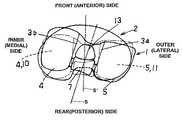
- FIG. 4is a top view of the femoral component of the artificial knee joint of the present invention.
- FIG. 5is a top view of the tibial component of the artificial knee joint of the present invention with partially cross-sectional side views;
- FIG. 6is a top view showing the correlation between the tibial component and femoral component of the artificial knee joint of the present invention when the knee is flexed;
- FIGS. 7A and 7Bare top views showing the relation of the post and cam of the artificial knee joint of the present invention.
- FIG. 1is a side view of an attached artificial knee joint in standing position as an example of the present invention.
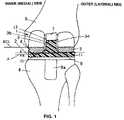
- FIG. 2is a cross section of a rear view of the same.
- the artificial knee joint of the present inventionis a combination of femoral component 1 and tibial component 2 .
- the femoral component 1is made from titanium alloy or another biocompatible metal; and it has inlet-shaped intercondylar groove 3 extending from the posterior end to near the anterior end disposed in the center and medial condyle 4 and lateral condyle 5 formed to substantially the shape of the letter C by the side view.
- the femoral component 1is attached to the distal end of femur 6 .
- the outline of medial condyle 4 and lateral condyle 5is convex from the front to the back, and this convex shape is longitudinally contiguous in a stripe.
- FIG. 4is a top view of femoral component 1 .
- Cam 7is provided horizontally over medial condyle 4 and lateral condyle 5 in the posterior portion of intercondylar groove 3 of the femoral component 1 .
- This cam 7has a drum shape with a depressed center; and in the shown example, the lateral condyle 5 side (or outer side) is formed to have a large diameter than the inner side.
- the cam 7is cut half way from the top along the line of the anterior surface of the posterior wall of femoral component 1 .
- the cam 7is made from the same material as femoral component 1 .
- lateral surface 3 a of intercondylar groove 3extends parallel to the center line of intercondylar groove 3 ; and medial surface 3 b extends, from the posterior end to the anterior end, in a gradual curve toward the lateral condyle 5 side beginning near the end of the cam 7 and connects the lateral surface 3 a.
- the tibial component 2is made from ultra-high-molecular-weight polyethylene or another medical resin, and it is attached to the proximal end of tibia 8 .
- the tibial component 2in this case is made from a biocompatible metal and is mounted on tibial base plate 9 with peg 9 a that will be inserted into tibia 8 .
- Medial articular surface 10 and lateral articular surface 11 that support medial condyle 4 and lateral condyle 5 of above-described femoral component 1 , respectively,are formed in the top surface of tibial component 2 separated by low protrusion 12 .
- articular surfaces 10 and 11are both concave following almost exactly the outline of medial condyle 4 and lateral condyle 5 , and this concave shape extends longitudinally.
- the medial condyle 4 and lateral condyle 5 and the projected plane above or below medial articular surface 10 and lateral articular surface 11are approximately the same size.
- FIG. 5is a top view of the tibial component 2 , showing also both sides in cross section.
- Both articular surfaces 10 and 11are concave in the center. However, starting from the middle, the posterior portion of lateral articular surface 11 is flat and turns slightly back medially at the posterior end side thereof. Moreover, post 13 is provided to stand near approximately the center of medial and lateral articular surfaces 10 and 11 .
- the post 13is substantially circular at both the anterior surface and posterior surface when viewed from above, but the curvature radius of the posterior surface is larger and gradually curves outward.
- the post 13has a substantially triangular shape that is formed by reducing thickness of the side surfaces from the side surfaces toward the anterior surface (the broken line is the outline when thickness is not reduced).
- the post 13 of the shown exampleis disposed slightly turned to the lateral condyle 5 side (twisted).
- the post 13forms one unit made from the same material as the tibial component 2 , but it can also be a separate unit and attached to the tibial component.
- concave part 14is formed in the posterior portion of the post 13 depressed slightly more than either of articular surfaces 10 and 11 , and the posterior portion of the concave part 14 is cut out to form a notched portion 15 .
- Femoral component 1 and tibial component 2 that form the above-described artificial knee jointrotate relatively with the flexion and extension of the knee. This is made possible by medial condyle 4 and lateral condyle 5 rotating as they roll and slide over the medial articular surface 10 and lateral articular surface 11 as the intercondylar groove 3 is guided by the post 13 .
- the angle of rotationis ⁇ 10 degrees to 150 degrees vertically.
- FIG. 3is a side view showing the state where femoral component I and tibial component 2 rotate relatively with flexion of the knee.
- the cam 7 of the femoral component 1is positioned away from the post 13 of the tibial component 2 ( FIG. 1 ).
- the medial condyle 4 and lateral condyle 5 of the femoral component 1roll and slide over the medial articular surface 10 and lateral articular surface 11 of the tibial component 2 , and the cam 7 comes closer to the post 13 as the knee flexes.
- FIG. 6is a top view of an artificial knee joint showing the above-described state.
- the cam 7has the shape of a drum wherein the lateral condyle 5 side (outer side) has a large diameter than the inner side, and the post 13 has the shape in which the surface that comes into contact with the post 13 , or its posterior surface, is a gradually outwardly curving surface that is disposed to be turned slightly to the lateral condyle 5 side. Therefore, there is further external turning of cam 7 or femoral component 1 , when it comes into contact with the post 13 .
- cam 7by way of increasing the outer diameter of cam 7 during the final stage of its rotation, it is possible to gradually increase the degree of the outward (lateral) turning of the femoral component 1 .
- Making the curvature radius of the drum shape of cam 7 approximately the same as the curvature radius of the posterior surface of post 13 in this casewill increase the contact surface area and thereby realize smooth movement as well as help to reduce wear.
- the cam 7is formed so that it has a larger diameter on the lateral condyle 5 side and the post 13 is disposed turned slightly toward the lateral condyle 5 side.
- Thisis a preferred embodiment for turning the femoral component 1 outwardly, but external turning of the lateral condyle 5 is not limited to this example and can be by other designs.
- FIG. 6shown in FIG. 6 is the tibial centerline S′ and the temoral centerline S.
- FIGS. 7A and 7Bshow the relationship between the cam 7 and post 13 in which the outward (or lateral) turning is made possible.
- the post 13can face the cam 7 square as shown in FIG. 7A .
- the lateral articular surface 11 side at the posterior surface of the post 13should be set back from the medial articular surface 10 side, that is, the center of the curvature (or radius) can be displaced outward as shown in FIG. 7B .
- the medial condyle 4is substantially uniformly thicker over the entire flexion-extension angle region than the lateral condyle 5 . Accordingly, the medial articular surface 10 of the tibial component 2 is substantially uniformly thinner over the entire flexion-extension angel region than the lateral articular surface 11 .
- the outside periphery of the medial condyle 4 and lateral condyle 5 and the medial articular surface 10 and lateral articular surface 11is graded such that the balance between tension and relaxation of the respective collateral ligaments will not be destroyed; and joint line L connecting the lowest points on the contact surface between medial articular surface 10 and lateral contact surface 11 that receive medial condyle 4 and lateral condyle 5 , respectively, is set to be lower in the medial direction, that is, is inclined inward, in the medial-lateral vertical cross section.
- the above designis made because it meets the structure of a biological knee joint; and by way of making the artificial knee the same as the biological knee, the balance between tension and relaxation of the collateral ligament is not damaged, and knee function (flexion-extension) after replacement will be the same as that of a biological knee.
- the inward inclination angle ⁇ of joint line JL in this caseis the same as that of a biological knee joint at 1 to 10 degrees, preferably 2 to 5 degrees.
- the curvature radius of the convex surface of the medial condyle 4is smaller than that of the lateral condyle 5 ; accordingly, the curvature radius of the concave surface of the medial articular surface 10 is smaller than that of the lateral articular surface 11 .
- the maximum thickness line M obtained by longitudinally connecting the points of maximum thickness of the medial condyle 4turns outward as it moves forward and the distance from maximum radial line M′ obtained by longitudinally connecting the points of maximum thickness of the lateral condyle 5 (becomes substantially straight longitudinally) becomes narrower (as a result, as seen from FIG. 5 , lines L and L′ corresponding to these lines of FIG. 4 are also formed by medial and lateral articular surfaces 10 and 11 ).
- a so-called toe-in designis created as shown in FIGS. 4 and 5 .
- turning of the tibia 8is further induced when the knee is flexed.
- the artificial knee joint of the present inventionwith the above-described unique shape and placement of the cam 7 and post 13 , and with the above-described unique shape of the intercondylar groove 3 and both articular surfaces 10 and 11 , it is possible to induce rotation during flexion without destroying the balance between tension and relaxation of the ligaments, particularly the collateral ligaments. Consequently, movement similar to that of a biological knee joint is made without any discomfort, and there is no reduction in function even a part of the ligaments is cut during surgery; and surgical time and other stress to the patient is reduced. Furthermore, when the joint line JL is made inclined inward, it is possible to realize deep flexion of 130 degrees or more because rotation is more easily induced during flexion and extension o the knee.
Landscapes
- Health & Medical Sciences (AREA)
- Orthopedic Medicine & Surgery (AREA)
- Physical Education & Sports Medicine (AREA)
- Cardiology (AREA)
- Oral & Maxillofacial Surgery (AREA)
- Transplantation (AREA)
- Engineering & Computer Science (AREA)
- Biomedical Technology (AREA)
- Heart & Thoracic Surgery (AREA)
- Vascular Medicine (AREA)
- Life Sciences & Earth Sciences (AREA)
- Animal Behavior & Ethology (AREA)
- General Health & Medical Sciences (AREA)
- Public Health (AREA)
- Veterinary Medicine (AREA)
- Prostheses (AREA)
Abstract
Description
- a femoral component to be attached to the distal end of a femur, and
- a tibial component to be attached to the proximal end of a tibia, the tibial component supporting the medial condyle and the lateral condyle of the femoral component by the medial articular surface and the lateral articular surface of the tibial component so that the femoral component and the tibial component are in relation of making rotation; and in the present invention,
- the tibial component is provided with a post that has an outwardly curving posterior surface, the post being disposed approximately in the longitudinal center between the two articular surfaces so that the post is inside the intercondylar groove which is formed between the medial condyle and the lateral condyle and extends from the posterior end to near the anterior end of the femoral component;
- the femoral component is provided with a cam that is disposed at the posterior portion of the intercondylar groove and comes into contact with the posterior surface of the post when the rotation proceeds; and
- the post and the cam are shaped so that the femoral component is turned outwardly with respect to the tibial component when the cam comes into contact with the post as a result of the rotation and as the rotation proceeds.
Claims (6)
Applications Claiming Priority (3)
| Application Number | Priority Date | Filing Date | Title |
|---|---|---|---|
| JP2004-75903 | 2004-03-17 | ||
| JP2004-075903 | 2004-03-17 | ||
| JP2004075903AJP3915989B2 (en) | 2004-03-17 | 2004-03-17 | Artificial knee joint |
Publications (2)
| Publication Number | Publication Date |
|---|---|
| US20050209701A1 US20050209701A1 (en) | 2005-09-22 |
| US7678152B2true US7678152B2 (en) | 2010-03-16 |
Family
ID=34934340
Family Applications (1)
| Application Number | Title | Priority Date | Filing Date |
|---|---|---|---|
| US11/081,990Active2027-01-02US7678152B2 (en) | 2004-03-17 | 2005-03-16 | Artificial knee joint |
Country Status (6)
| Country | Link |
|---|---|
| US (1) | US7678152B2 (en) |
| EP (1) | EP1591082B1 (en) |
| JP (1) | JP3915989B2 (en) |
| AT (1) | ATE444036T1 (en) |
| DE (1) | DE602005016858D1 (en) |
| ES (1) | ES2331575T3 (en) |
Cited By (58)
| Publication number | Priority date | Publication date | Assignee | Title |
|---|---|---|---|---|
| US20080288080A1 (en)* | 2005-08-24 | 2008-11-20 | Kantilal Hastimal Sancheti | Knee joint prosthesis |
| US20090319049A1 (en)* | 2008-02-18 | 2009-12-24 | Maxx Orthopedics, Inc. | Total Knee Replacement Prosthesis With High Order NURBS Surfaces |
| US20090326666A1 (en)* | 2008-06-30 | 2009-12-31 | Wyss Joseph G | Posterior stabilized orthopaedic prosthesis |
| US20100016979A1 (en)* | 2008-07-16 | 2010-01-21 | Depuy Products, Inc. | Knee prostheses with enhanced kinematics |
| US20100161067A1 (en)* | 2008-12-23 | 2010-06-24 | Aesculap Ag | Knee prosthesis |
| US20100286788A1 (en)* | 2009-05-07 | 2010-11-11 | Richard David Komistek | Anterior stabilized knee implant |
| US20100324583A1 (en)* | 2009-06-17 | 2010-12-23 | Lawton Gmbh & Co. Kg | Surgical Instrument |
| US20110125279A1 (en)* | 2009-11-16 | 2011-05-26 | New York Society For The Ruptured And Crippled Maintaining The Hospital For Special Surgery | Constrained condylar knee device |
| US20110125275A1 (en)* | 2009-11-16 | 2011-05-26 | New York Society For The Ruptured And Crippled Maintaining The Hospital For Special Surgery | Prosthetic condylar joints with articulating bearing surfaces having a translating contact point during rotation thereof |
| US20110184525A1 (en)* | 2010-01-13 | 2011-07-28 | Aesculap Ag | Knee joint endoprosthesis |
| US8128703B2 (en) | 2007-09-28 | 2012-03-06 | Depuy Products, Inc. | Fixed-bearing knee prosthesis having interchangeable components |
| US8187335B2 (en) | 2008-06-30 | 2012-05-29 | Depuy Products, Inc. | Posterior stabilized orthopaedic knee prosthesis having controlled condylar curvature |
| US20120136452A1 (en)* | 2009-07-10 | 2012-05-31 | Medizinische Hochschule Hannover | Knee joint prosthesis and related method |
| US8192498B2 (en) | 2008-06-30 | 2012-06-05 | Depuy Products, Inc. | Posterior cructiate-retaining orthopaedic knee prosthesis having controlled condylar curvature |
| US8236061B2 (en) | 2008-06-30 | 2012-08-07 | Depuy Products, Inc. | Orthopaedic knee prosthesis having controlled condylar curvature |
| US8287601B2 (en) | 2010-09-30 | 2012-10-16 | Depuy Products, Inc. | Femoral component of a knee prosthesis having an angled cement pocket |
| US8317870B2 (en) | 2010-09-30 | 2012-11-27 | Depuy Products, Inc. | Tibial component of a knee prosthesis having an angled cement pocket |
| US20130018477A1 (en)* | 2011-07-13 | 2013-01-17 | The General Hospital Corporation D/B/A Massachusetts General Hospital | Methods and Devices for Knee Joint Replacement with Anterior Cruciate Ligament Substitution |
| US8491661B2 (en) | 2010-10-05 | 2013-07-23 | Aesculap Ag | Knee joint prosthesis |
| US8491662B2 (en) | 2008-12-23 | 2013-07-23 | Aesculap Ag | Knee prosthesis |
| US20130226305A1 (en)* | 2010-09-10 | 2013-08-29 | Zimmer Gmbh | Femoral prosthesis with medialized patellar groove |
| US8551179B2 (en) | 2011-06-16 | 2013-10-08 | Zimmer, Inc. | Femoral prosthesis system having provisional component with visual indicators |
| US8636807B2 (en) | 2006-03-21 | 2014-01-28 | Depuy (Ireland) | Moment induced total arthroplasty prosthetic |
| US8690954B2 (en) | 2011-11-18 | 2014-04-08 | Zimmer, Inc. | Tibial bearing component for a knee prosthesis with improved articular characteristics |
| US8828086B2 (en) | 2008-06-30 | 2014-09-09 | Depuy (Ireland) | Orthopaedic femoral component having controlled condylar curvature |
| US8932365B2 (en) | 2011-06-16 | 2015-01-13 | Zimmer, Inc. | Femoral component for a knee prosthesis with improved articular characteristics |
| US20150032217A1 (en)* | 2009-02-25 | 2015-01-29 | Conformis, Inc. | Patient-Adapted and Improved Orthopedic Implants, Designs and Related Tools |
| US9060868B2 (en) | 2011-06-16 | 2015-06-23 | Zimmer, Inc. | Femoral component for a knee prosthesis with bone compacting ridge |
| US9119723B2 (en) | 2008-06-30 | 2015-09-01 | Depuy (Ireland) | Posterior stabilized orthopaedic prosthesis assembly |
| US9168145B2 (en) | 2008-06-30 | 2015-10-27 | Depuy (Ireland) | Posterior stabilized orthopaedic knee prosthesis having controlled condylar curvature |
| US9204967B2 (en) | 2007-09-28 | 2015-12-08 | Depuy (Ireland) | Fixed-bearing knee prosthesis having interchangeable components |
| US9220600B2 (en) | 2008-12-23 | 2015-12-29 | Aesculap Implant Systems, Llc | Knee prosthesis |
| US9308095B2 (en) | 2011-06-16 | 2016-04-12 | Zimmer, Inc. | Femoral component for a knee prosthesis with improved articular characteristics |
| US9364332B2 (en) | 2011-09-27 | 2016-06-14 | Kyocera Medical Corporation | Artificial knee joint implant |
| US9398956B2 (en) | 2007-09-25 | 2016-07-26 | Depuy (Ireland) | Fixed-bearing knee prosthesis having interchangeable components |
| US9495483B2 (en) | 2001-05-25 | 2016-11-15 | Conformis, Inc. | Automated Systems for manufacturing patient-specific orthopedic implants and instrumentation |
| US9492280B2 (en) | 2000-11-28 | 2016-11-15 | Medidea, Llc | Multiple-cam, posterior-stabilized knee prosthesis |
| US9592127B2 (en) | 2005-12-15 | 2017-03-14 | Zimmer, Inc. | Distal femoral knee prostheses |
| US9603711B2 (en) | 2001-05-25 | 2017-03-28 | Conformis, Inc. | Patient-adapted and improved articular implants, designs and related guide tools |
| US9877790B2 (en)* | 2001-05-25 | 2018-01-30 | Conformis, Inc. | Tibial implant and systems with variable slope |
| US10085839B2 (en) | 2004-01-05 | 2018-10-02 | Conformis, Inc. | Patient-specific and patient-engineered orthopedic implants |
| US10130375B2 (en) | 2014-07-31 | 2018-11-20 | Zimmer, Inc. | Instruments and methods in performing kinematically-aligned total knee arthroplasty |
| US10136997B2 (en) | 2015-09-29 | 2018-11-27 | Zimmer, Inc. | Tibial prosthesis for tibia with varus resection |
| US10179052B2 (en) | 2016-07-28 | 2019-01-15 | Depuy Ireland Unlimited Company | Total knee implant prosthesis assembly and method |
| US10188530B2 (en) | 2010-12-17 | 2019-01-29 | Zimmer, Inc. | Provisional tibial prosthesis system |
| US10195041B2 (en) | 2010-07-24 | 2019-02-05 | Zimmer, Inc. | Asymmetric tibial components for a knee prosthesis |
| US10265181B2 (en) | 2011-11-21 | 2019-04-23 | Zimmer, Inc. | Tibial baseplate with asymmetric placement of fixation structures |
| US10278827B2 (en) | 2015-09-21 | 2019-05-07 | Zimmer, Inc. | Prosthesis system including tibial bearing component |
| US10413415B2 (en) | 2010-09-10 | 2019-09-17 | Zimmer, Inc. | Motion facilitating tibial components for a knee prosthesis |
| US10456263B2 (en) | 2009-02-24 | 2019-10-29 | Conformis, Inc. | Patient-adapted and improved articular implants, designs and related guide tools |
| US10470889B2 (en) | 2010-07-24 | 2019-11-12 | Zimmer, Inc. | Asymmetric tibial components for a knee prosthesis |
| US10543099B2 (en) | 2010-07-24 | 2020-01-28 | Zimmer, Inc. | Tibial prosthesis |
| US10675153B2 (en) | 2017-03-10 | 2020-06-09 | Zimmer, Inc. | Tibial prosthesis with tibial bearing component securing feature |
| US10835380B2 (en) | 2018-04-30 | 2020-11-17 | Zimmer, Inc. | Posterior stabilized prosthesis system |
| US11173038B2 (en) | 2019-02-22 | 2021-11-16 | Stryker European Operations Limited | Total ankle prosthesis |
| US11324598B2 (en) | 2013-08-30 | 2022-05-10 | Zimmer, Inc. | Method for optimizing implant designs |
| US11324599B2 (en) | 2017-05-12 | 2022-05-10 | Zimmer, Inc. | Femoral prostheses with upsizing and downsizing capabilities |
| US11426282B2 (en) | 2017-11-16 | 2022-08-30 | Zimmer, Inc. | Implants for adding joint inclination to a knee arthroplasty |
Families Citing this family (38)
| Publication number | Priority date | Publication date | Assignee | Title |
|---|---|---|---|---|
| ES2465090T3 (en) | 2002-12-20 | 2014-06-05 | Smith & Nephew, Inc. | High performance knee prostheses |
| FR2854792B1 (en)* | 2003-05-12 | 2005-09-09 | Tornier Sa | GAME OF PROTHETIC ELEMENTS FOR A TIBIAL PROTHETIC SET |
| CA2542619C (en) | 2003-10-17 | 2011-10-11 | Smith & Nephew, Inc. | High flexion articular insert |
| DE202004003133U1 (en)* | 2004-02-26 | 2004-07-29 | Aap Implantate Ag | Joint replacement tibial plateau |
| GB0510193D0 (en)* | 2005-05-19 | 2005-06-22 | Mcminn Derek J W | Knee prosthesis |
| US8211181B2 (en) | 2005-12-14 | 2012-07-03 | New York University | Surface guided knee replacement |
| US8292964B2 (en)* | 2005-12-14 | 2012-10-23 | New York University | Surface guided knee replacement |
| CA2656359C (en) | 2006-06-30 | 2016-11-22 | Smith & Nephew, Inc. | Anatomical motion hinged prosthesis |
| US8313530B2 (en)* | 2007-02-12 | 2012-11-20 | Jmea Corporation | Total knee arthroplasty system |
| KR100930727B1 (en)* | 2008-01-08 | 2009-12-09 | 주식회사 코렌텍 | Artificial knee joint with improved post and improved cam structure |
| US8292965B2 (en)* | 2008-02-11 | 2012-10-23 | New York University | Knee joint with a ramp |
| US8298288B2 (en)* | 2008-06-24 | 2012-10-30 | New York University | Recess-ramp knee joint prosthesis |
| US8480752B2 (en) | 2008-06-30 | 2013-07-09 | DePuy Synthes Products, LLC | Tibial bearing having increased axial-rotation |
| US8075626B2 (en)* | 2008-06-30 | 2011-12-13 | Depuy Products, Inc. | Orthopaedic knee prosthesis having increased axial-rotation |
| GB0812631D0 (en)* | 2008-07-10 | 2008-08-20 | Imp Innovations Ltd | Modular knee implants |
| US7981159B2 (en)* | 2008-07-16 | 2011-07-19 | Depuy Products, Inc. | Antero-posterior placement of axis of rotation for a rotating platform |
| WO2010085656A1 (en)* | 2009-01-23 | 2010-07-29 | Zimmer, Inc. | Posterior stabilized total knee prosthesis |
| CA2756226C (en)* | 2009-03-27 | 2017-01-24 | Smith & Nephew Orthopaedics Ag | Artificial knee joint |
| US8496666B2 (en) | 2009-08-11 | 2013-07-30 | Imds Corporation | Instrumentation for mobile bearing prosthetics |
| US9095453B2 (en)* | 2009-08-11 | 2015-08-04 | Michael D. Ries | Position adjustable trial systems for prosthetic implants |
| US8568485B2 (en)* | 2009-08-11 | 2013-10-29 | Imds Corporation | Articulating trials for prosthetic implants |
| US8382848B2 (en)* | 2009-08-11 | 2013-02-26 | Imds Corporation | Position adjustable trial systems for prosthetic implants |
| US8998997B2 (en) | 2009-08-11 | 2015-04-07 | Michael D. Ries | Implantable mobile bearing prosthetics |
| US9132014B2 (en) | 2010-04-13 | 2015-09-15 | Zimmer, Inc. | Anterior cruciate ligament substituting knee implants |
| CA2808090C (en) | 2010-08-12 | 2018-09-11 | Smith & Nephew, Inc. | Structures for use in orthopaedic implant fixation and methods of installation onto a bone |
| US20120185054A1 (en)* | 2011-01-19 | 2012-07-19 | Wright Medical Technology, Inc. | Medial pivot posterior stabilized knee implant system |
| CN103327937B (en)* | 2011-01-27 | 2017-08-08 | 史密夫和内修有限公司 | constrained knee prosthesis |
| KR101255057B1 (en)* | 2011-05-06 | 2013-04-16 | 주식회사 코리아본뱅크 | post-cam structure of artficial knee joints |
| KR101304446B1 (en) | 2011-05-11 | 2013-09-05 | 심영복 | bearing component of artficial knee joints |
| WO2013007747A1 (en)* | 2011-07-13 | 2013-01-17 | Zimmer Gmbh | Femoral knee prosthesis with diverging lateral condyle |
| CN103126787B (en)* | 2011-11-28 | 2015-03-04 | 北京纳通科技集团有限公司 | Knee-joint prosthesis |
| GB2521871B (en)* | 2014-01-07 | 2020-04-01 | James Wallace Mcminn Derek | Knee prosthesis with congruent and incongruent condyle bearing surfaces |
| US11612487B2 (en) | 2014-01-07 | 2023-03-28 | Derek James Wallace McMinn | Knee prosthesis |
| JP6499674B2 (en)* | 2014-02-10 | 2019-04-10 | リマコーポレート・ソチエタ・ペル・アチオニLimacorporate S.P.A. | Artificial knee joint |
| JP6305268B2 (en)* | 2014-08-07 | 2018-04-04 | スミス・アンド・ネフュー・オルソペディクス・アーゲー | Artificial knee joint |
| CN114449981A (en)* | 2019-10-10 | 2022-05-06 | 国立大学法人爱媛大学 | Artificial knee joint, beam member, insert member, and base plate used for the artificial knee joint |
| CN111437077A (en)* | 2020-04-23 | 2020-07-24 | 北京市春立正达医疗器械股份有限公司 | Anatomical knee prosthesis |
| CN113524254B (en)* | 2021-07-12 | 2022-11-08 | 吉林大学 | Bionic condyle type knee joint |
Citations (26)
| Publication number | Priority date | Publication date | Assignee | Title |
|---|---|---|---|---|
| US4261064A (en)* | 1978-02-17 | 1981-04-14 | Helfet Arthur Jacob | Bicondylar joint prosthesis |
| US4298992A (en)* | 1980-01-21 | 1981-11-10 | New York Society For The Relief Of The Ruptured And Crippled | Posteriorly stabilized total knee joint prosthesis |
| EP0123016A1 (en) | 1983-03-23 | 1984-10-31 | GebràDer Sulzer Aktiengesellschaft | Knee joint endoprosthesis |
| US5147405A (en)* | 1990-02-07 | 1992-09-15 | Boehringer Mannheim Corporation | Knee prosthesis |
| US5192328A (en)* | 1989-09-29 | 1993-03-09 | Winters Thomas F | Knee joint replacement apparatus |
| FR2701387A1 (en) | 1993-02-10 | 1994-08-19 | Reach | Postero-stabilised knee prosthesis |
| FR2702651A1 (en) | 1993-03-16 | 1994-09-23 | Erato | Knee prosthesis |
| US5549686A (en)* | 1994-06-06 | 1996-08-27 | Zimmer, Inc. | Knee prosthesis having a tapered cam |
| US5702458A (en)* | 1994-12-09 | 1997-12-30 | New York Society For The Ruptured And Crippled Maintaining The Hospital For Special Surgery | Joint prosthesis |
| WO1999030649A1 (en) | 1997-12-17 | 1999-06-24 | Memento S.A. | Total knee prosthesis with tibial plateau mobile in rotation |
| JPH11313845A (en) | 1998-03-10 | 1999-11-16 | Bristol Myers Squibb Co | Artificial knee joint implant, femur knee joint implant and module used together with femur knee joint implant |
| US6068658A (en)* | 1997-03-13 | 2000-05-30 | Zimmer Ltd. | Prosthesis for knee replacement |
| US6168629B1 (en)* | 1997-10-14 | 2001-01-02 | Tornier S.A. | Femoral component for knee prosthesis |
| US6235060B1 (en)* | 1996-11-13 | 2001-05-22 | Hjs Gelenk System Gmbh | Artificial joint, in particular endoprosthesis for replacing natural joints |
| US6428577B1 (en)* | 1998-05-20 | 2002-08-06 | Smith & Nephew, Inc. | Mobile bearing knee prosthesis |
| US6475241B2 (en)* | 2000-03-13 | 2002-11-05 | Biomedical Engineering Trust I | Posterior stabilized knee replacement with bearing translation for knees with retained collateral ligaments |
| JP2003116892A (en) | 2001-10-10 | 2003-04-22 | Kyocera Corp | Artificial knee joint |
| US6558421B1 (en)* | 2000-09-19 | 2003-05-06 | Barry M. Fell | Surgically implantable knee prosthesis |
| US6582469B1 (en)* | 1997-12-12 | 2003-06-24 | Tornier S.A. | Knee prosthesis |
| US6589283B1 (en)* | 2001-05-15 | 2003-07-08 | Biomet, Inc. | Elongated femoral component |
| US20030153977A1 (en)* | 2002-02-13 | 2003-08-14 | Nakashima Propeller Co., Ltd. | Artificial knee joint |
| US6660039B1 (en)* | 1998-05-20 | 2003-12-09 | Smith & Nephew, Inc. | Mobile bearing knee prosthesis |
| EP1374805A2 (en) | 2002-06-28 | 2004-01-02 | DePuy Orthopaedics, Inc. | Modular knee joint prosthesis |
| US20040243244A1 (en)* | 2002-12-20 | 2004-12-02 | Jason Otto | High performance knee prostheses |
| US6972039B2 (en)* | 1999-03-01 | 2005-12-06 | Biomet, Inc. | Floating bearing knee joint prosthesis with a fixed tibial post |
| US7066963B2 (en)* | 2004-02-26 | 2006-06-27 | Hjs Gelenk-System Gmbh | Tibia plateau for a replacement joint |
- 2004
- 2004-03-17JPJP2004075903Apatent/JP3915989B2/ennot_activeExpired - Lifetime
- 2005
- 2005-03-16USUS11/081,990patent/US7678152B2/enactiveActive
- 2005-03-17DEDE602005016858Tpatent/DE602005016858D1/ennot_activeExpired - Lifetime
- 2005-03-17EPEP05005891Apatent/EP1591082B1/ennot_activeExpired - Lifetime
- 2005-03-17ESES05005891Tpatent/ES2331575T3/ennot_activeExpired - Lifetime
- 2005-03-17ATAT05005891Tpatent/ATE444036T1/ennot_activeIP Right Cessation
Patent Citations (28)
| Publication number | Priority date | Publication date | Assignee | Title |
|---|---|---|---|---|
| US4261064A (en)* | 1978-02-17 | 1981-04-14 | Helfet Arthur Jacob | Bicondylar joint prosthesis |
| US4298992A (en)* | 1980-01-21 | 1981-11-10 | New York Society For The Relief Of The Ruptured And Crippled | Posteriorly stabilized total knee joint prosthesis |
| EP0123016A1 (en) | 1983-03-23 | 1984-10-31 | GebràDer Sulzer Aktiengesellschaft | Knee joint endoprosthesis |
| US5192328A (en)* | 1989-09-29 | 1993-03-09 | Winters Thomas F | Knee joint replacement apparatus |
| US5147405A (en)* | 1990-02-07 | 1992-09-15 | Boehringer Mannheim Corporation | Knee prosthesis |
| FR2701387A1 (en) | 1993-02-10 | 1994-08-19 | Reach | Postero-stabilised knee prosthesis |
| FR2702651A1 (en) | 1993-03-16 | 1994-09-23 | Erato | Knee prosthesis |
| US5549686A (en)* | 1994-06-06 | 1996-08-27 | Zimmer, Inc. | Knee prosthesis having a tapered cam |
| US5702458A (en)* | 1994-12-09 | 1997-12-30 | New York Society For The Ruptured And Crippled Maintaining The Hospital For Special Surgery | Joint prosthesis |
| US6235060B1 (en)* | 1996-11-13 | 2001-05-22 | Hjs Gelenk System Gmbh | Artificial joint, in particular endoprosthesis for replacing natural joints |
| US6068658A (en)* | 1997-03-13 | 2000-05-30 | Zimmer Ltd. | Prosthesis for knee replacement |
| US6168629B1 (en)* | 1997-10-14 | 2001-01-02 | Tornier S.A. | Femoral component for knee prosthesis |
| US6582469B1 (en)* | 1997-12-12 | 2003-06-24 | Tornier S.A. | Knee prosthesis |
| WO1999030649A1 (en) | 1997-12-17 | 1999-06-24 | Memento S.A. | Total knee prosthesis with tibial plateau mobile in rotation |
| JPH11313845A (en) | 1998-03-10 | 1999-11-16 | Bristol Myers Squibb Co | Artificial knee joint implant, femur knee joint implant and module used together with femur knee joint implant |
| US6428577B1 (en)* | 1998-05-20 | 2002-08-06 | Smith & Nephew, Inc. | Mobile bearing knee prosthesis |
| US6660039B1 (en)* | 1998-05-20 | 2003-12-09 | Smith & Nephew, Inc. | Mobile bearing knee prosthesis |
| US6972039B2 (en)* | 1999-03-01 | 2005-12-06 | Biomet, Inc. | Floating bearing knee joint prosthesis with a fixed tibial post |
| US6475241B2 (en)* | 2000-03-13 | 2002-11-05 | Biomedical Engineering Trust I | Posterior stabilized knee replacement with bearing translation for knees with retained collateral ligaments |
| US6558421B1 (en)* | 2000-09-19 | 2003-05-06 | Barry M. Fell | Surgically implantable knee prosthesis |
| US6589283B1 (en)* | 2001-05-15 | 2003-07-08 | Biomet, Inc. | Elongated femoral component |
| JP2003116892A (en) | 2001-10-10 | 2003-04-22 | Kyocera Corp | Artificial knee joint |
| US20030153977A1 (en)* | 2002-02-13 | 2003-08-14 | Nakashima Propeller Co., Ltd. | Artificial knee joint |
| JP2003230582A (en) | 2002-02-13 | 2003-08-19 | Toru Suguro | Artificial knee joint |
| EP1336395A2 (en) | 2002-02-13 | 2003-08-20 | Toru Suguro | An artificial knee joint |
| EP1374805A2 (en) | 2002-06-28 | 2004-01-02 | DePuy Orthopaedics, Inc. | Modular knee joint prosthesis |
| US20040243244A1 (en)* | 2002-12-20 | 2004-12-02 | Jason Otto | High performance knee prostheses |
| US7066963B2 (en)* | 2004-02-26 | 2006-06-27 | Hjs Gelenk-System Gmbh | Tibia plateau for a replacement joint |
Non-Patent Citations (2)
| Title |
|---|
| "Anatomy and Kinematics of the Knee Joint". Feb. 8, 2006. Duke Orthopaedics. Wheeless' Textbook of Orthopaedics. Online. http://www.wheelssonline.com/ortho/anatomy-and -kinemantics-of -the-joint.* |
| "Anatomy and Kinematics of the Knee Joint". Feb. 8, 2006. Duke Orthopaedics. Wheeless' Textbook of Orthopaedics. Online. http://www.wheelssonline.com/ortho/anatomy—and —kinemantics—of —the—joint.* |
Cited By (141)
| Publication number | Priority date | Publication date | Assignee | Title |
|---|---|---|---|---|
| US9492280B2 (en) | 2000-11-28 | 2016-11-15 | Medidea, Llc | Multiple-cam, posterior-stabilized knee prosthesis |
| US10188521B2 (en) | 2000-11-28 | 2019-01-29 | Medidea, Llc | Multiple-cam, posterior-stabilized knee prosthesis |
| US9603711B2 (en) | 2001-05-25 | 2017-03-28 | Conformis, Inc. | Patient-adapted and improved articular implants, designs and related guide tools |
| US9495483B2 (en) | 2001-05-25 | 2016-11-15 | Conformis, Inc. | Automated Systems for manufacturing patient-specific orthopedic implants and instrumentation |
| US9877790B2 (en)* | 2001-05-25 | 2018-01-30 | Conformis, Inc. | Tibial implant and systems with variable slope |
| US10085839B2 (en) | 2004-01-05 | 2018-10-02 | Conformis, Inc. | Patient-specific and patient-engineered orthopedic implants |
| US20080288080A1 (en)* | 2005-08-24 | 2008-11-20 | Kantilal Hastimal Sancheti | Knee joint prosthesis |
| US9592127B2 (en) | 2005-12-15 | 2017-03-14 | Zimmer, Inc. | Distal femoral knee prostheses |
| US10433966B2 (en) | 2005-12-15 | 2019-10-08 | Zimmer, Inc. | Distal femoral knee prostheses |
| US9254197B2 (en) | 2006-03-21 | 2016-02-09 | Depuy (Ireland) | Moment induced total arthroplasty prosthetic |
| US10045849B2 (en) | 2006-03-21 | 2018-08-14 | Depuy Ireland Unlimited Company | Moment induced total arthroplasty prosthetic |
| US10932915B2 (en) | 2006-03-21 | 2021-03-02 | Depuy Ireland Unlimited Company | Moment induced total arthroplasty prosthetic |
| US8636807B2 (en) | 2006-03-21 | 2014-01-28 | Depuy (Ireland) | Moment induced total arthroplasty prosthetic |
| US9398956B2 (en) | 2007-09-25 | 2016-07-26 | Depuy (Ireland) | Fixed-bearing knee prosthesis having interchangeable components |
| US8128703B2 (en) | 2007-09-28 | 2012-03-06 | Depuy Products, Inc. | Fixed-bearing knee prosthesis having interchangeable components |
| US9204967B2 (en) | 2007-09-28 | 2015-12-08 | Depuy (Ireland) | Fixed-bearing knee prosthesis having interchangeable components |
| US9788955B2 (en)* | 2008-02-18 | 2017-10-17 | Maxx Orthopedics, Inc. | Total knee replacement prosthesis with high order NURBS surfaces |
| US20090319049A1 (en)* | 2008-02-18 | 2009-12-24 | Maxx Orthopedics, Inc. | Total Knee Replacement Prosthesis With High Order NURBS Surfaces |
| US9204968B2 (en) | 2008-06-30 | 2015-12-08 | Depuy (Ireland) | Posterior stabilized orthopaedic prosthesis |
| US9119723B2 (en) | 2008-06-30 | 2015-09-01 | Depuy (Ireland) | Posterior stabilized orthopaedic prosthesis assembly |
| US11369478B2 (en) | 2008-06-30 | 2022-06-28 | Depuy Ireland Unlimited Company | Orthopaedic knee prosthesis having controlled condylar curvature |
| US20090326666A1 (en)* | 2008-06-30 | 2009-12-31 | Wyss Joseph G | Posterior stabilized orthopaedic prosthesis |
| US10849760B2 (en) | 2008-06-30 | 2020-12-01 | Depuy Ireland Unlimited Company | Orthopaedic knee prosthesis having controlled condylar curvature |
| US10729551B2 (en) | 2008-06-30 | 2020-08-04 | Depuy Ireland Unlimited Company | Orthopaedic knee prosthesis having controlled condylar curvature |
| US9539099B2 (en) | 2008-06-30 | 2017-01-10 | Depuy Ireland Unlimited Company | Orthopaedic knee prosthesis having controlled condylar curvature |
| US9452053B2 (en) | 2008-06-30 | 2016-09-27 | Depuy (Ireland) | Orthopaedic knee prosthesis having controlled condylar curvature |
| US8734522B2 (en) | 2008-06-30 | 2014-05-27 | Depuy (Ireland) | Posterior stabilized orthopaedic prosthesis |
| US10543098B2 (en) | 2008-06-30 | 2020-01-28 | Depuy Ireland Unlimited Company | Orthopaedic femoral component having controlled condylar curvature |
| US8784496B2 (en) | 2008-06-30 | 2014-07-22 | Depuy (Ireland) | Orthopaedic knee prosthesis having controlled condylar curvature |
| US8795380B2 (en) | 2008-06-30 | 2014-08-05 | Depuy (Ireland) | Orthopaedic knee prosthesis having controlled condylar curvature |
| US8828086B2 (en) | 2008-06-30 | 2014-09-09 | Depuy (Ireland) | Orthopaedic femoral component having controlled condylar curvature |
| US8834575B2 (en) | 2008-06-30 | 2014-09-16 | Depuy (Ireland) | Posterior stabilized orthopaedic knee prosthesis having controlled condylar curvature |
| US9326864B2 (en) | 2008-06-30 | 2016-05-03 | Depuy (Ireland) | Orthopaedic knee prosthesis having controlled condylar curvature |
| US12109119B2 (en) | 2008-06-30 | 2024-10-08 | Depuy Ireland Unlimited Company | Orthopaedic femoral component having controlled condylar curvature |
| US8236061B2 (en) | 2008-06-30 | 2012-08-07 | Depuy Products, Inc. | Orthopaedic knee prosthesis having controlled condylar curvature |
| US8206451B2 (en) | 2008-06-30 | 2012-06-26 | Depuy Products, Inc. | Posterior stabilized orthopaedic prosthesis |
| US9931216B2 (en) | 2008-06-30 | 2018-04-03 | Depuy Ireland Unlimited Company | Orthopaedic femoral component having controlled condylar curvature |
| US10265180B2 (en) | 2008-06-30 | 2019-04-23 | Depuy Ireland Unlimited Company | Orthopaedic knee prosthesis having controlled condylar curvature |
| US12059356B2 (en) | 2008-06-30 | 2024-08-13 | Depuy Ireland Unlimited Company | Orthopaedic knee prosthesis having controlled condylar curvature |
| US9937049B2 (en) | 2008-06-30 | 2018-04-10 | Depuy Ireland Unlimited Company | Orthopaedic knee prosthesis having controlled condylar curvature |
| US10179051B2 (en) | 2008-06-30 | 2019-01-15 | Depuy Ireland Unlimited Company | Orthopaedic knee prosthesis having controlled condylar curvature |
| US8192498B2 (en) | 2008-06-30 | 2012-06-05 | Depuy Products, Inc. | Posterior cructiate-retaining orthopaedic knee prosthesis having controlled condylar curvature |
| US9220601B2 (en) | 2008-06-30 | 2015-12-29 | Depuy (Ireland) | Orthopaedic femoral component having controlled condylar curvature |
| US11337823B2 (en) | 2008-06-30 | 2022-05-24 | Depuy Ireland Unlimited Company | Orthopaedic femoral component having controlled condylar curvature |
| US11730602B2 (en) | 2008-06-30 | 2023-08-22 | Depuy Ireland Unlimited Company | Orthopaedic knee prosthesis having controlled condylar curvature |
| US9168145B2 (en) | 2008-06-30 | 2015-10-27 | Depuy (Ireland) | Posterior stabilized orthopaedic knee prosthesis having controlled condylar curvature |
| US8187335B2 (en) | 2008-06-30 | 2012-05-29 | Depuy Products, Inc. | Posterior stabilized orthopaedic knee prosthesis having controlled condylar curvature |
| US20100016979A1 (en)* | 2008-07-16 | 2010-01-21 | Depuy Products, Inc. | Knee prostheses with enhanced kinematics |
| US8202323B2 (en) | 2008-07-16 | 2012-06-19 | Depuy Products, Inc. | Knee prostheses with enhanced kinematics |
| US8491662B2 (en) | 2008-12-23 | 2013-07-23 | Aesculap Ag | Knee prosthesis |
| US20100161067A1 (en)* | 2008-12-23 | 2010-06-24 | Aesculap Ag | Knee prosthesis |
| US9220600B2 (en) | 2008-12-23 | 2015-12-29 | Aesculap Implant Systems, Llc | Knee prosthesis |
| US10456263B2 (en) | 2009-02-24 | 2019-10-29 | Conformis, Inc. | Patient-adapted and improved articular implants, designs and related guide tools |
| US9956048B2 (en) | 2009-02-24 | 2018-05-01 | Conformis, Inc. | Standard or customized knee implant with asymmetric femoral component and tibial offset |
| US9956047B2 (en) | 2009-02-24 | 2018-05-01 | Conformis, Inc. | Patient-adapted and improved articular implants, designs and related guide tools |
| US20150032217A1 (en)* | 2009-02-25 | 2015-01-29 | Conformis, Inc. | Patient-Adapted and Improved Orthopedic Implants, Designs and Related Tools |
| US10500055B2 (en) | 2009-05-07 | 2019-12-10 | Depuy Ireland Unlimited Company | Anterior stabilized knee implant |
| US8915965B2 (en) | 2009-05-07 | 2014-12-23 | Depuy (Ireland) | Anterior stabilized knee implant |
| US9408703B2 (en) | 2009-05-07 | 2016-08-09 | Depuy (Ireland) | Anterior stabilized knee implant |
| US20200107936A1 (en)* | 2009-05-07 | 2020-04-09 | Depuy Ireland Unlimited Company | Anterior stabilized knee implant |
| US20100286788A1 (en)* | 2009-05-07 | 2010-11-11 | Richard David Komistek | Anterior stabilized knee implant |
| US11564800B2 (en)* | 2009-05-07 | 2023-01-31 | Depuy Ireland Unlimited Company | Anterior stabilized knee implant |
| US9962264B2 (en) | 2009-05-07 | 2018-05-08 | Depuy Ireland Unlimited Company | Anterior stabilized knee implant |
| US20100324583A1 (en)* | 2009-06-17 | 2010-12-23 | Lawton Gmbh & Co. Kg | Surgical Instrument |
| US9833323B2 (en)* | 2009-07-10 | 2017-12-05 | Aesculap Ag | Knee joint prosthesis and related method |
| US20120136452A1 (en)* | 2009-07-10 | 2012-05-31 | Medizinische Hochschule Hannover | Knee joint prosthesis and related method |
| US9999512B2 (en) | 2009-07-10 | 2018-06-19 | Aesculap Ag | Knee joint prosthesis and related method |
| US8870964B2 (en)* | 2009-11-16 | 2014-10-28 | New York Society For The Ruptured And Crippled Maintaining The Hospital For Special Surgery | Prosthetic condylar joints with articulating bearing surfaces having a translating contact point during rotation thereof |
| US20110125275A1 (en)* | 2009-11-16 | 2011-05-26 | New York Society For The Ruptured And Crippled Maintaining The Hospital For Special Surgery | Prosthetic condylar joints with articulating bearing surfaces having a translating contact point during rotation thereof |
| US8900315B2 (en)* | 2009-11-16 | 2014-12-02 | New York Society For The Ruptured And Crippled Maintaining The Hospital For Special Surgery | Constrained condylar knee device |
| US20110125279A1 (en)* | 2009-11-16 | 2011-05-26 | New York Society For The Ruptured And Crippled Maintaining The Hospital For Special Surgery | Constrained condylar knee device |
| US20110184525A1 (en)* | 2010-01-13 | 2011-07-28 | Aesculap Ag | Knee joint endoprosthesis |
| US11224519B2 (en) | 2010-07-24 | 2022-01-18 | Zimmer, Inc. | Asymmetric tibial components for a knee prosthesis |
| US10470889B2 (en) | 2010-07-24 | 2019-11-12 | Zimmer, Inc. | Asymmetric tibial components for a knee prosthesis |
| US10195041B2 (en) | 2010-07-24 | 2019-02-05 | Zimmer, Inc. | Asymmetric tibial components for a knee prosthesis |
| US12239540B2 (en) | 2010-07-24 | 2025-03-04 | Zimmer, Inc. | Asymmetric tibial components for a knee prosthesis |
| US10543099B2 (en) | 2010-07-24 | 2020-01-28 | Zimmer, Inc. | Tibial prosthesis |
| US9867708B2 (en)* | 2010-09-10 | 2018-01-16 | Zimmer Gmbh | Femoral prosthesis with lateralized patellar groove |
| US11471288B2 (en) | 2010-09-10 | 2022-10-18 | Zimmer, Inc. | Motion facilitating tibial components for a knee prosthesis |
| US10322004B2 (en) | 2010-09-10 | 2019-06-18 | Zimmer Gmbh | Femoral prosthesis with lateralized patellar groove |
| US10413415B2 (en) | 2010-09-10 | 2019-09-17 | Zimmer, Inc. | Motion facilitating tibial components for a knee prosthesis |
| US20150374500A1 (en)* | 2010-09-10 | 2015-12-31 | Zimmer Gmbh | Femoral prosthesis with medialized patellar groove |
| US20130226305A1 (en)* | 2010-09-10 | 2013-08-29 | Zimmer Gmbh | Femoral prosthesis with medialized patellar groove |
| US9173744B2 (en)* | 2010-09-10 | 2015-11-03 | Zimmer Gmbh | Femoral prosthesis with medialized patellar groove |
| US8317870B2 (en) | 2010-09-30 | 2012-11-27 | Depuy Products, Inc. | Tibial component of a knee prosthesis having an angled cement pocket |
| US8845746B2 (en) | 2010-09-30 | 2014-09-30 | Depuy (Ireland) | Femoral component of a knee prosthesis having an angled posterior cement pocket |
| US9724202B2 (en) | 2010-09-30 | 2017-08-08 | Depuy Ireland Unlimited Company | Femoral component of a knee prosthesis having an angled cement pocket |
| US8287601B2 (en) | 2010-09-30 | 2012-10-16 | Depuy Products, Inc. | Femoral component of a knee prosthesis having an angled cement pocket |
| US9155627B2 (en) | 2010-10-05 | 2015-10-13 | Aesculap Ag | Knee joint prosthesis |
| US8491661B2 (en) | 2010-10-05 | 2013-07-23 | Aesculap Ag | Knee joint prosthesis |
| US10188530B2 (en) | 2010-12-17 | 2019-01-29 | Zimmer, Inc. | Provisional tibial prosthesis system |
| US10441429B2 (en) | 2011-06-16 | 2019-10-15 | Zimmer, Inc. | Femoral component for a knee prosthesis with improved articular characteristics |
| US9060868B2 (en) | 2011-06-16 | 2015-06-23 | Zimmer, Inc. | Femoral component for a knee prosthesis with bone compacting ridge |
| US12213889B2 (en) | 2011-06-16 | 2025-02-04 | Zimmer, Inc. | Femoral component for a knee prosthesis with improved articular characteristics |
| US9993345B2 (en) | 2011-06-16 | 2018-06-12 | Zimmer, Inc. | Femoral prosthesis system |
| US10045850B2 (en) | 2011-06-16 | 2018-08-14 | Zimmer, Inc. | Femoral component for a knee prosthesis with improved articular characteristics |
| US12048630B2 (en) | 2011-06-16 | 2024-07-30 | Zimmer, Inc. | Femoral component for a knee prosthesis with improved articular characteristics |
| US9629723B2 (en) | 2011-06-16 | 2017-04-25 | Zimmer, Inc. | Femoral component for a knee prosthesis with improved articular characteristics |
| US8932365B2 (en) | 2011-06-16 | 2015-01-13 | Zimmer, Inc. | Femoral component for a knee prosthesis with improved articular characteristics |
| US11246710B2 (en) | 2011-06-16 | 2022-02-15 | Zimmer, Inc. | Femoral component for a knee prosthesis with improved articular characteristics |
| US8551179B2 (en) | 2011-06-16 | 2013-10-08 | Zimmer, Inc. | Femoral prosthesis system having provisional component with visual indicators |
| US10070966B2 (en) | 2011-06-16 | 2018-09-11 | Zimmer, Inc. | Femoral component for a knee prosthesis with bone compacting ridge |
| US9308095B2 (en) | 2011-06-16 | 2016-04-12 | Zimmer, Inc. | Femoral component for a knee prosthesis with improved articular characteristics |
| US20130018477A1 (en)* | 2011-07-13 | 2013-01-17 | The General Hospital Corporation D/B/A Massachusetts General Hospital | Methods and Devices for Knee Joint Replacement with Anterior Cruciate Ligament Substitution |
| US9005299B2 (en)* | 2011-07-13 | 2015-04-14 | The General Hospital Corporation | Methods and devices for knee joint replacement with anterior cruciate ligament substitution |
| US9707085B2 (en)* | 2011-07-13 | 2017-07-18 | The General Hospital Corporation | Methods and devices for knee joint replacement with anterior cruciate ligament substitution |
| US20150164646A1 (en)* | 2011-07-13 | 2015-06-18 | The General Hospital Corporation | Methods and Devices for Knee Joint Replacement with Anterior Cruciate Ligament Substitution |
| US9364332B2 (en) | 2011-09-27 | 2016-06-14 | Kyocera Medical Corporation | Artificial knee joint implant |
| US9295558B2 (en) | 2011-11-18 | 2016-03-29 | Zimmer, Inc. | Tibial bearing component for a knee prosthesis with improved articular characteristics |
| US10898337B2 (en) | 2011-11-18 | 2021-01-26 | Zimmer, Inc. | Tibial bearing component for a knee prosthesis with improved articular characteristics |
| US12383407B2 (en) | 2011-11-18 | 2025-08-12 | Zimmer, Inc. | Tibial bearing component for a knee prosthesis with improved articular characteristics |
| US9655729B2 (en) | 2011-11-18 | 2017-05-23 | Zimmer, Inc. | Tibial bearing component for a knee prosthesis with improved articular characteristics |
| US8764838B2 (en) | 2011-11-18 | 2014-07-01 | Zimmer, Inc. | Tibial bearing component for a knee prosthesis with improved articular characteristics |
| US9788954B2 (en) | 2011-11-18 | 2017-10-17 | Zimmer, Inc. | Tibial bearing component for a knee prosthesis with improved articular characteristics |
| US9204970B2 (en) | 2011-11-18 | 2015-12-08 | Zimmer, Inc. | Tibial bearing component for a knee prosthesis with improved articular characteristics |
| US9655728B2 (en) | 2011-11-18 | 2017-05-23 | Zimmer, Inc. | Tibial bearing component for a knee prosthesis with improved articular characteristics |
| US9186255B2 (en) | 2011-11-18 | 2015-11-17 | Zimmer, Inc. | Tibial bearing component for a knee prosthesis with improved articular characteristics |
| US8690954B2 (en) | 2011-11-18 | 2014-04-08 | Zimmer, Inc. | Tibial bearing component for a knee prosthesis with improved articular characteristics |
| US9072607B2 (en) | 2011-11-18 | 2015-07-07 | Zimmer, Inc. | Tibial bearing component for a knee prosthesis with improved articular characteristics |
| AU2017251736B2 (en)* | 2011-11-18 | 2018-01-25 | Zimmer, Inc. | Tibial bearing component for a knee prosthesis with improved articular characteristics |
| US9925050B2 (en) | 2011-11-18 | 2018-03-27 | Zimmer, Inc. | Tibial bearing component for a knee prosthesis with improved articular characteristics |
| US8858643B2 (en) | 2011-11-18 | 2014-10-14 | Zimmer, Inc. | Tibial bearing component for a knee prosthesis with improved articular characteristics |
| US10265181B2 (en) | 2011-11-21 | 2019-04-23 | Zimmer, Inc. | Tibial baseplate with asymmetric placement of fixation structures |
| US11324598B2 (en) | 2013-08-30 | 2022-05-10 | Zimmer, Inc. | Method for optimizing implant designs |
| US10939923B2 (en) | 2014-07-31 | 2021-03-09 | Zimmer, Inc. | Instruments and methods in performing kinematically-aligned total knee arthroplasty |
| US10130375B2 (en) | 2014-07-31 | 2018-11-20 | Zimmer, Inc. | Instruments and methods in performing kinematically-aligned total knee arthroplasty |
| US10278827B2 (en) | 2015-09-21 | 2019-05-07 | Zimmer, Inc. | Prosthesis system including tibial bearing component |
| US11160659B2 (en) | 2015-09-21 | 2021-11-02 | Zimmer, Inc. | Prosthesis system including tibial bearing component |
| US10631991B2 (en) | 2015-09-29 | 2020-04-28 | Zimmer, Inc. | Tibial prosthesis for tibia with varus resection |
| US10136997B2 (en) | 2015-09-29 | 2018-11-27 | Zimmer, Inc. | Tibial prosthesis for tibia with varus resection |
| US11491018B2 (en) | 2015-09-29 | 2022-11-08 | Zimmer, Inc. | Tibial prosthesis for tibia with varus resection |
| US12115080B2 (en) | 2016-07-28 | 2024-10-15 | Depuy Ireland Unlimited Company | Total knee implant prosthesis assembly and method |
| US10179052B2 (en) | 2016-07-28 | 2019-01-15 | Depuy Ireland Unlimited Company | Total knee implant prosthesis assembly and method |
| US11382756B2 (en) | 2016-07-28 | 2022-07-12 | Depuy Ireland Unlimited Company | Total knee implant prosthesis assembly and method |
| US11547571B2 (en) | 2017-03-10 | 2023-01-10 | Zimmer, Inc. | Tibial prosthesis with tibial bearing component securing feature |
| US10675153B2 (en) | 2017-03-10 | 2020-06-09 | Zimmer, Inc. | Tibial prosthesis with tibial bearing component securing feature |
| US11324599B2 (en) | 2017-05-12 | 2022-05-10 | Zimmer, Inc. | Femoral prostheses with upsizing and downsizing capabilities |
| US11426282B2 (en) | 2017-11-16 | 2022-08-30 | Zimmer, Inc. | Implants for adding joint inclination to a knee arthroplasty |
| US11911279B2 (en) | 2018-04-30 | 2024-02-27 | Zimmer, Inc. | Posterior stabilized prosthesis system |
| US10835380B2 (en) | 2018-04-30 | 2020-11-17 | Zimmer, Inc. | Posterior stabilized prosthesis system |
| US11173038B2 (en) | 2019-02-22 | 2021-11-16 | Stryker European Operations Limited | Total ankle prosthesis |
Also Published As
| Publication number | Publication date |
|---|---|
| EP1591082B1 (en) | 2009-09-30 |
| JP2005261538A (en) | 2005-09-29 |
| EP1591082A3 (en) | 2005-11-16 |
| ES2331575T3 (en) | 2010-01-08 |
| US20050209701A1 (en) | 2005-09-22 |
| ATE444036T1 (en) | 2009-10-15 |
| EP1591082A2 (en) | 2005-11-02 |
| JP3915989B2 (en) | 2007-05-16 |
| DE602005016858D1 (en) | 2009-11-12 |
Similar Documents
| Publication | Publication Date | Title |
|---|---|---|
| US7678152B2 (en) | Artificial knee joint | |
| US4944756A (en) | Prosthetic knee joint with improved patellar component tracking | |
| EP1336395B1 (en) | An artificial knee joint | |
| US9642711B2 (en) | High flexion articular insert | |
| US5035700A (en) | Prosthetic knee joint with improved patellar component tracking | |
| CN102917670B (en) | Implant for restoring normal range of flexion and knee joint kinematics | |
| JP4045194B2 (en) | Artificial knee joint | |
| JP4820547B2 (en) | Self-aligning knee prosthesis | |
| ES2534653T3 (en) | Orthopedic prostheses | |
| ES2396228T3 (en) | Patellar support implant | |
| CN107661161B (en) | Total knee implant prosthesis assembly and method | |
| US9289305B2 (en) | Total knee arthroplasty with symmetric femoral implant having double Q-angle trochlear groove | |
| US20150257889A1 (en) | Femoral component for a femoral knee implant system | |
| AU2019465494B2 (en) | Knee joint implant preventing hyperextension | |
| US20130190884A1 (en) | Artificial knee joint | |
| US20250090335A1 (en) | Medially stabilising knee endoprosthesis | |
| CN116137809A (en) | Insert for use in knee prosthesis | |
| AU2014200110A1 (en) | High flexion articular insert |
Legal Events
| Date | Code | Title | Description |
|---|---|---|---|
| AS | Assignment | Owner name:NAKASHIMA PROPELLER CO., LTD., JAPAN Free format text:ASSIGNMENT OF ASSIGNORS INTEREST;ASSIGNORS:SUGURO, TORU;KURAMOTO, KOICHI;YAMAMOTO, KEITARO;REEL/FRAME:016394/0291 Effective date:20050311 Owner name:SUGURO, TORU, JAPAN Free format text:ASSIGNMENT OF ASSIGNORS INTEREST;ASSIGNORS:SUGURO, TORU;KURAMOTO, KOICHI;YAMAMOTO, KEITARO;REEL/FRAME:016394/0291 Effective date:20050311 Owner name:NAKASHIMA PROPELLER CO., LTD.,JAPAN Free format text:ASSIGNMENT OF ASSIGNORS INTEREST;ASSIGNORS:SUGURO, TORU;KURAMOTO, KOICHI;YAMAMOTO, KEITARO;REEL/FRAME:016394/0291 Effective date:20050311 Owner name:SUGURO, TORU,JAPAN Free format text:ASSIGNMENT OF ASSIGNORS INTEREST;ASSIGNORS:SUGURO, TORU;KURAMOTO, KOICHI;YAMAMOTO, KEITARO;REEL/FRAME:016394/0291 Effective date:20050311 | |
| STCF | Information on status: patent grant | Free format text:PATENTED CASE | |
| FEPP | Fee payment procedure | Free format text:PAYOR NUMBER ASSIGNED (ORIGINAL EVENT CODE: ASPN); ENTITY STATUS OF PATENT OWNER: SMALL ENTITY | |
| FPAY | Fee payment | Year of fee payment:4 | |
| FPAY | Fee payment | Year of fee payment:8 | |
| MAFP | Maintenance fee payment | Free format text:PAYMENT OF MAINTENANCE FEE, 12TH YR, SMALL ENTITY (ORIGINAL EVENT CODE: M2553); ENTITY STATUS OF PATENT OWNER: SMALL ENTITY Year of fee payment:12 |