US7678139B2 - Pedicle screw assembly - Google Patents
Pedicle screw assemblyDownload PDFInfo
- Publication number
- US7678139B2 US7678139B2US11/109,124US10912405AUS7678139B2US 7678139 B2US7678139 B2US 7678139B2US 10912405 AUS10912405 AUS 10912405AUS 7678139 B2US7678139 B2US 7678139B2
- Authority
- US
- United States
- Prior art keywords
- coupling element
- saddle
- stabilizer rod
- assembly
- rod
- Prior art date
- Legal status (The legal status is an assumption and is not a legal conclusion. Google has not performed a legal analysis and makes no representation as to the accuracy of the status listed.)
- Expired - Fee Related, expires
Links
- 230000008878couplingEffects0.000claimsabstractdescription165
- 238000010168coupling processMethods0.000claimsabstractdescription165
- 238000005859coupling reactionMethods0.000claimsabstractdescription165
- 230000006835compressionEffects0.000claimsabstractdescription98
- 238000007906compressionMethods0.000claimsabstractdescription98
- 239000003381stabilizerSubstances0.000claimsabstractdescription69
- 210000000988bone and boneAnatomy0.000claimsdescription32
- 230000004927fusionEffects0.000abstractdescription8
- 230000000712assemblyEffects0.000abstractdescription5
- 238000000429assemblyMethods0.000abstractdescription5
- 230000006641stabilisationEffects0.000description4
- 238000011105stabilizationMethods0.000description4
- 230000000295complement effectEffects0.000description3
- 238000000034methodMethods0.000description3
- 230000013011matingEffects0.000description2
- 240000007643Phytolacca americanaSpecies0.000description1
- 235000009074Phytolacca americanaNutrition0.000description1
- 206010058907Spinal deformityDiseases0.000description1
- 208000020339Spinal injuryDiseases0.000description1
- RTAQQCXQSZGOHL-UHFFFAOYSA-NTitaniumChemical compound[Ti]RTAQQCXQSZGOHL-UHFFFAOYSA-N0.000description1
- 230000007547defectEffects0.000description1
- -1for exampleSubstances0.000description1
- 230000008570general processEffects0.000description1
- 230000002452interceptive effectEffects0.000description1
- 239000000463materialSubstances0.000description1
- 230000008569processEffects0.000description1
- 230000000087stabilizing effectEffects0.000description1
- 229910001220stainless steelInorganic materials0.000description1
- 239000010935stainless steelSubstances0.000description1
- 229910052719titaniumInorganic materials0.000description1
- 239000010936titaniumSubstances0.000description1
Images


Classifications
- A—HUMAN NECESSITIES
- A61—MEDICAL OR VETERINARY SCIENCE; HYGIENE
- A61B—DIAGNOSIS; SURGERY; IDENTIFICATION
- A61B17/00—Surgical instruments, devices or methods
- A61B17/56—Surgical instruments or methods for treatment of bones or joints; Devices specially adapted therefor
- A61B17/58—Surgical instruments or methods for treatment of bones or joints; Devices specially adapted therefor for osteosynthesis, e.g. bone plates, screws or setting implements
- A61B17/68—Internal fixation devices, including fasteners and spinal fixators, even if a part thereof projects from the skin
- A61B17/84—Fasteners therefor or fasteners being internal fixation devices
- A61B17/86—Pins or screws or threaded wires; nuts therefor
- A61B17/8605—Heads, i.e. proximal ends projecting from bone
- A—HUMAN NECESSITIES
- A61—MEDICAL OR VETERINARY SCIENCE; HYGIENE
- A61B—DIAGNOSIS; SURGERY; IDENTIFICATION
- A61B17/00—Surgical instruments, devices or methods
- A61B17/56—Surgical instruments or methods for treatment of bones or joints; Devices specially adapted therefor
- A61B17/58—Surgical instruments or methods for treatment of bones or joints; Devices specially adapted therefor for osteosynthesis, e.g. bone plates, screws or setting implements
- A61B17/68—Internal fixation devices, including fasteners and spinal fixators, even if a part thereof projects from the skin
- A61B17/70—Spinal positioners or stabilisers, e.g. stabilisers comprising fluid filler in an implant
- A61B17/7001—Screws or hooks combined with longitudinal elements which do not contact vertebrae
- A61B17/7002—Longitudinal elements, e.g. rods
- A61B17/7011—Longitudinal element being non-straight, e.g. curved, angled or branched
- A—HUMAN NECESSITIES
- A61—MEDICAL OR VETERINARY SCIENCE; HYGIENE
- A61B—DIAGNOSIS; SURGERY; IDENTIFICATION
- A61B17/00—Surgical instruments, devices or methods
- A61B17/56—Surgical instruments or methods for treatment of bones or joints; Devices specially adapted therefor
- A61B17/58—Surgical instruments or methods for treatment of bones or joints; Devices specially adapted therefor for osteosynthesis, e.g. bone plates, screws or setting implements
- A61B17/68—Internal fixation devices, including fasteners and spinal fixators, even if a part thereof projects from the skin
- A61B17/70—Spinal positioners or stabilisers, e.g. stabilisers comprising fluid filler in an implant
- A61B17/7001—Screws or hooks combined with longitudinal elements which do not contact vertebrae
- A61B17/7032—Screws or hooks with U-shaped head or back through which longitudinal rods pass
- A—HUMAN NECESSITIES
- A61—MEDICAL OR VETERINARY SCIENCE; HYGIENE
- A61B—DIAGNOSIS; SURGERY; IDENTIFICATION
- A61B17/00—Surgical instruments, devices or methods
- A61B17/56—Surgical instruments or methods for treatment of bones or joints; Devices specially adapted therefor
- A61B17/58—Surgical instruments or methods for treatment of bones or joints; Devices specially adapted therefor for osteosynthesis, e.g. bone plates, screws or setting implements
- A61B17/68—Internal fixation devices, including fasteners and spinal fixators, even if a part thereof projects from the skin
- A61B17/70—Spinal positioners or stabilisers, e.g. stabilisers comprising fluid filler in an implant
- A61B17/7001—Screws or hooks combined with longitudinal elements which do not contact vertebrae
- A61B17/7035—Screws or hooks, wherein a rod-clamping part and a bone-anchoring part can pivot relative to each other
- A61B17/7037—Screws or hooks, wherein a rod-clamping part and a bone-anchoring part can pivot relative to each other wherein pivoting is blocked when the rod is clamped
- A—HUMAN NECESSITIES
- A61—MEDICAL OR VETERINARY SCIENCE; HYGIENE
- A61B—DIAGNOSIS; SURGERY; IDENTIFICATION
- A61B17/00—Surgical instruments, devices or methods
- A61B17/56—Surgical instruments or methods for treatment of bones or joints; Devices specially adapted therefor
- A61B17/58—Surgical instruments or methods for treatment of bones or joints; Devices specially adapted therefor for osteosynthesis, e.g. bone plates, screws or setting implements
- A61B17/68—Internal fixation devices, including fasteners and spinal fixators, even if a part thereof projects from the skin
- A61B17/70—Spinal positioners or stabilisers, e.g. stabilisers comprising fluid filler in an implant
- A61B17/7001—Screws or hooks combined with longitudinal elements which do not contact vertebrae
- A61B17/7002—Longitudinal elements, e.g. rods
Definitions
- This disclosureis directed at skeletal bone fixation systems, and more particularly to a fixation assembly for vertebrae of a spinal column.
- a typical spinal fixation assemblyincludes a fixation device, such as a screw or hook, that can be attached to a portion of a first vertebral body.
- the screwcan be coupled to a stabilization member, such as an elongate rod, that can be linked to one or more additional vertebral bodies using additional screws.
- two or more bone screws and/or hooksare secured to a vertebral body that is to be stabilized. After the screws are secured to the vertebral bodies, the screws are coupled to a spinal stabilization rod that restricts movement of the stabilized vertebra. It is important that the screws have a secure coupling with the spinal stabilization rod in order to prevent movement of the rod relative to the screw after placement.
- the systemincludes a tulip-like coupling element that can be coupled to a fixation element, such as, for example, a screw with a head that removably mates with the coupling element.
- the coupling element and fixation elementare configured to be coupled to an elongate stabilizer, such as a rod, that is positioned between a top and a bottom saddle.
- a compression membersuch as a compression nut, is configured to mate with the coupling element and provides a compressive force to the top and bottom saddles to secure the elongate stabilizer therebetween.
- the top and bottom saddlesare movably positioned within the coupling element such that they can gradually reposition and self-align into a secure engagement with the stabilizer as the compression member provides the compressive force.
- a bone stabilizer assemblycomprising a fixation element adapted to engage a bone and having a head portion and shank portion; a coupling element having an internal bore sized to receive the shank portion of the fixation element and a seat adapted to support the head portion of the fixation element, the coupling element further adapted to receive a stabilizer rod; a bottom saddle movably mounted in the coupling element below the stabilizer rod when the stabilizer rod is in the coupling element; a top saddle positioned above the stabilizer rod when the stabilizer rod is in the coupling element; and a compression nut engagable with the coupling element, the compression nut adapted to rotatingly move downward into the coupling element to translate a force to the top saddle to compress the stabilizer rod between the top saddle and the bottom saddle, wherein the top saddle is rotatingly attached to the compression nut such that the top saddle self-aligns into a secure engagement with the stabilizer rod as the top saddle moves downward toward the stabilizer rod.
- a bone stabilizer assemblycomprising a fixation element adapted to engage a bone; a coupling element adapted to couple to the fixation element and to a stabilizer rod; a bottom saddle movably attached to the coupling element and having a first contact surface for contacting a bottom of the stabilizer rod when the stabilizer rod is coupled to the coupling element; a compression element adapted to be rotatingly coupled to the coupling element for transmitting a compression force against the stabilizer rod when the stabilizer rod is coupled to the coupling element; and a top saddle rotatingly attached to the compression element, wherein the top saddle is positioned between the compression element and the stabilizer rod when the stabilizer rod and the compression element are coupled to the coupling element.
- a bone stabilizer assemblycomprising a fixation element having a head portion and a shank portion; a coupling element having (1) an internal bore for receiving the shank portion of the fixation element; (2) a seat for receiving the head portion of the fixation element, and (3) a pair of opposed projections having internal threads; a compression nut having external threads engagable with the internal threads of the coupling element such that the compression nut can be rotated downwardly into the coupling element; a top saddle rotatingly attached to a bottom of the compression nut for engaging a top region of a stabilizer rod; and a bottom saddle positioned in the coupling element above the seat for engaging a bottom region of the stabilizer rod, wherein the compression nut provides a downward compression force that compresses the stabilizer rod between the top and bottom saddle when the stabilizer rod is positioned in the coupling element.
- FIG. 1shows an exploded, perspective view of bone fixation system.
- FIG. 2shows a first side view of the bone fixation system.
- FIG. 3shows a cross-sectional view of the bone fixation system along line A-A of FIG. 2 .
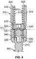
- FIG. 4shows an enlarged view of the region of the bone fixation system contained in circle B of FIG. 3 .
- FIG. 5shows an exploded, perspective view of another embodiment of the bone fixation system.
- FIG. 6shows a first side view of the bone fixation system of FIG. 5 .
- FIG. 7shows a cross-sectional view of the bone fixation of FIG. 5 system along line A-A of FIG. 5 .
- FIG. 8shows an enlarged view of the region of the bone fixation system contained in circle B of FIG. 7 .
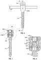
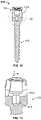
- FIG. 9shows a side view of a mono-axial bone fixation system.
- FIG. 10shows a cross-sectional view of the system of FIG. 9 along line B-B of FIG. 9 .
- FIG. 11shows a cross-sectional view of the system of FIG. 9 along line A-A of FIG. 9 .
- FIG. 12shows another side view of a mono-axial bone fixation system.
- FIG. 13shows an enlarged view of the region of the bone fixation system contained in circle 13 of FIG. 12 .
- FIG. 14shows a side view of a stabilizer rod configured to couple to the bone fixation system of FIG. 12 .
- FIG. 15shows a schematic side view of a top saddle component of the bone fixation system.
- the systemincludes a tulip-like coupling element that can be coupled to a fixation element, such as, for example, a screw with a head that removably mates with the coupling element.
- the coupling element and fixation elementare configured to be coupled to an elongate stabilizer, such as a rod, that is positioned between a top and a bottom saddle.
- a compression membersuch as a compression nut, is configured to mate with the coupling element and provides a compressive force to the top and bottom saddles to secure the elongate stabilizer therebetween.
- the top and bottom saddlesare movably positioned within the coupling element such that they can gradually reposition into a secure engagement with the stabilizer as the compression member provides the compressive force.
- FIGS. 1-4show various views of a polyaxial spinal fusion assembly which is used for the fixation and manipulation of the spine.
- FIG. 1shows an exploded view of the polyaxial spinal fusion assembly.
- FIG. 2shows a side view of the assembly in an assembled state.
- the assemblyincludes an anchor 105 comprised of a fixation element 110 that is removably coupled to a coupling element 115 .
- the assemblyfurther includes a stabilizer, such as an elongate rod 120 , that can be compressively secured to the anchor 105 , as described below.
- FIG. 3shows a side, cross-sectional view of the assembly 100 .
- the fixation element 110can be coupled to a skeletal structure, such as a spinal vertebra.
- the coupling element 115is used to couple the fixation element 110 to the stabilizer, which can be coupled to multiple fixation elements using additional couplers.
- the fixation element 110can comprise, for example, an elongate screw having a threaded shank portion 205 with external threads that can be screwed into a bone structure such as a vertebra.
- a head 210is positioned at the upper end of the shank portion 205 .
- the head 210has a shape, such as a rounded shape, that is configured to mate with a correspondingly-shaped seat structure in the coupling element 115 , as described below.
- a drive coupler, such as a drive cavity 215is located within or on the head 210 of the fixation element 110 .
- the drive cavity 215has a shape that is configured to receive a device that can impart rotational movement to the fixation element 110 in order to screw the fixation element into a bone structure.
- the drive cavity 215can have a hexagonal shape that is configured to receive therein an allen-style wrench.
- the drive couplerneed not be a cavity that mates with an allen-style wrench and that other types of drive couplers can be used.
- the fixation elementcan be in forms other than a shank, including, for example, a hook or clamp. Indeed, it should be appreciated that any structure or component configured for attachment to a bone structure can be used in place of the shank portion of the fixation element.
- the coupling element 115is configured to receive the fixation element 110 and the elongate rod 120 .
- the coupling element 115has an internal bore 305 that extends through the coupling element 115 along an axis A (the axis A is shown in FIG. 2 ).
- the internal bore 305is sized to receive at least the shank portion 205 of the fixation element therethrough.
- a pair of laterally-opposed, upwardly extending projections 310are separated by the bore 305 .
- the projections 310have internal, threaded surfaces.
- a pair of u-shaped channels 315extend through the coupling element for receiving therein the rod 120 , which extends along an axis that is transverse to the axis A of the bore 305 .
- the upper ends of the projections 310define an entry port that is sized to receive therein a compression nut 410 (shown in FIGS. 1 and 4 ), as described below.
- the compression nut 410is described herein as having outer threads that are configured to mate with the inner threads 313 on the opposed inner surfaces of the projections 310 of the coupling element 115 .
- the entry portis sized and shaped to facilitate an easy entry of the compression nut 410 into or over the projections 310 of the coupling element.
- a bottom saddle 320 and a top saddle 325are configured to be positioned within the coupling element 115 .
- the saddleseach define a contact surface 330 (shown in FIG. 4 ) that having a contour selected to complement a contour of the outer surface of the rod 120 .
- the contact surfaces 330have rounded contours that complement the rounded, outer surface of the rod 120 .
- the contact surfaces 330can have any shape or contour that complement the shape and contour of the rod 120 .
- the complementing shapes and contours between the contact surfaces 330 and rod 120provide a maximum amount of contact area between the saddles and rod 120 .
- the rod 120is shown having a rounded or convex outer surface.
- the contact surfaces 330 of the saddles 320 , 325are correspondingly rounded or concave such that the elongate rod 120 can fit snug between the saddles 320 , 325 with the contact surfaces 330 of the saddles 320 , 325 providing a wide area of contact with the outer surface of the elongate rod 120 .
- the contour and shape of the contact surfaces 330can be varied to match any contour of the outer surface of the elongate rod 120 or in any manner to maximize the amount of grip between the saddles and the elongate rod.
- the bottom saddle 320has an internal bore that axially aligns with the bore 305 in the coupling element 115 when the bottom saddle 320 is placed in the coupling element 115 . Furthermore, the bottom saddle 320 has a rounded outer surface that includes a pair of pin cavities 335 (shown in FIGS. 1 and 4 ) positioned, for example, on opposed locations on the bottom saddle 320 . Each of the cavities 335 aligns with a corresponding pin aperture 340 (shown in FIGS. 1 and 4 ) that extends through the coupling element 115 .
- the bottom saddle 320is secured within the coupling element 115 by positioning the saddle between the projections 310 such that each pin cavity 335 in the bottom saddle 320 aligns with a corresponding pin aperture 340 in the coupling element 115 .
- a pin 345(shown in FIGS. 1 and 4 ) is then inserted through each pin aperture 340 such that one end of the pin 345 pokes into a corresponding pin cavity 335 .
- the pin 345provides an interfering engagement with the pin cavity 335 and the pin aperture 340 to thereby secure the bottom saddle 320 in place relative to the coupling element 115 .
- the diameters of the pins 345can be smaller than the diameters of the pin cavities 335 so that there is some play therebetween. Furthermore, the pins 345 can have lengths that extend only partially into the pin cavities 335 to provide some play therebetween. This permits the bottom saddle to “float” in the coupling element such that the position and the orientation of the bottom saddle 320 can be varied slightly. That is, the bottom saddle 320 can be moved slightly upward or downward and from side to side when mounted in the coupling element 115 . The bottom saddle 320 can also rotate slightly when mounted in the coupling element 115 . Thus, the bottom saddle 320 can movingly adjust into a secure engagement with the elongate rod 120 when compressed against the elongate rod 120 during assembly, as described below.
- the top saddle 325is rotatingly mounted within a compression nut 410 that has outer threads that are configured to mate with the threads on the internal surface of the opposed projections 310 of the coupling element 115 .
- the top saddle 325has an upper projection 316 ( FIG. 1 ) that rotatingly mates with the compression nut 410 and permits the top saddle 325 to rotate and/or tilt relative to the compression nut 410 when attached thereto.
- the top saddle 325is positioned immediately below the compression nut 410 , as shown in FIG. 4 .
- the top saddleis fixedly attached to the compression nut 410 such that it does not rotate relative to the compression nut.
- the compression nut 410When the compression nut 410 is attached to the top saddle 325 , the compression nut 410 is rotatingly coupled to the coupling element 115 by mating the outer threads of the compression nut 410 with the inner threads of the coupling element 115 . The compression nut 410 is repeatedly rotated over a 360 degree rotational angle to lower the compression nut into the coupling element.
- the compression nut 410is described herein as having outer threads that mate with inner threads on the opposed projections 310 . As described below, this advantageously permits a thread configuration that prevents projections 310 from spreading apart from one another as the compression nut 410 is screwed into the coupling element 115 .
- the compression nut 410can be modified to have an annular shape with internal threads that mate with corresponding outer threads on the opposed projections 310 .
- the threads 313 on the inner surfaces of the projections 310 of the coupling element 115are tilted inwardly with respect to a horizontal axis (a horizontal axis is perpendicular to the axis A shown in FIG. 2 ).
- the threads on the exterior of the compression nut 410are correspondingly tilted.
- the tilted thread configurationcauses the compression nut 410 , when screwed into the coupling element 115 , to prevent the projections 310 from spreading apart relative to one another. Rather, the compression nut 410 applies a radially inward (i.e., toward the axis A) force to the projections 310 as the compression nut 410 is screwed into the coupling element 115 . This keeps the projections 410 from spreading apart while the compression nut 410 is screwed into the coupling element 115 .
- the threadsare buttressed such that it requires less force to lower or tighten the compression nut 410 into the coupling element 115 and greater force to untighten or loosen the compression nut 410 relative to the coupling element 115 . In this manner, it is unlikely that the compression nut will inadvertently loosen from the coupling element over time.
- Thisis advantageous, as the assembly can often be mounted in a vertebra for an extended period of time (such as several years) and it is undesirable for the compression nut to inadvertently loosen from the coupling element.
- the various components of the assembly 100are manufactured of an inert material, such as, for example, stainless steel or titanium.
- the shank portion 205 of the fixation element 110is inserted through the bore 305 in the coupling element 115 .
- the rounded head 210abuts against and sits within a correspondingly-shaped seat 327 in the bottom of the coupling element 115 in a ball/socket manner, as shown in the cross-sectional view of FIG. 4 .
- the seat 327can have a rounded shape that is configured to provide a secure fit between the head 210 and the coupling element 115 . Because the seat 327 is rounded, the head 210 can be rotated within the seat 326 to move the axis of the shank portion 205 to a desired orientation relative to the coupling element 115 and thereby provide a poly-axial configuration.
- the fixation element 110With the fixation element 110 seated in the coupling element 115 , an operator can position the assembly relative to a bone structure such as a vertebra.
- a drive devicesuch as an allen wrench
- the bottom saddle 320has an internal bore that is sized to receive therethrough the drive device to provide access to the head 210 of the fixation element 110 .
- the bottom saddle 320is attached to the coupling element using the pins 345 , which mate with the pin cavities 335 in the side of the bottom saddle 320 .
- the bottom saddle 320essentially floats and can move somewhat relative to the coupling element 115 . That is, the bottom saddle 320 is attached to the coupling element 115 in a manner that permits movement of the bottom saddle 320 relative to the coupling element 115 and/or relative to the elongate rod 120 .
- the bottom saddle 320adjusts in position as the compression nut is tightened downward into the coupling element 115 , as described below.
- the rod 120is loaded into the coupling element 115 by inserting the rod downwardly between the projections 310 through the unshaped channels 315 , as shown in FIG. 2 .
- the outer surface of the rod 120will eventually abut and sit against the corresponding rounded contact surface 330 of the bottom saddle 320 .
- the compression nut 410 and attached upper saddle 325are then threaded downward into the coupling element 115 by mating the external threads on the compression nut 410 with the internal threads on the projections 310 of the coupling element 115 .
- the compression nut 410can be threaded downward until the rod 120 is compressed between the top and bottom saddles, with the compression nut 410 providing the compression force.
- the coupling element 115has an entry port for the compression nut 410 that facilitates entry or coupling of the compression nut 410 into the coupling element 115 .
- the entry portis defined by the upper edges of the projections 310 .
- the entry porthas a structure that guides the compression nut into a proper engagement with the coupling element 115 .
- one or more large chamfers 425are located on the upper, inner edge of the projections 310 of the coupling element 115 to provide ease of entry for the compression nut 410 into the coupling element 115 .
- the chamfers 425are angled with the angle being in the range of thirty degrees to sixty degrees relative to vertical axis A, although the angle can vary.
- the chamfers 425guide the compression nut 410 into proper alignment with the coupling element 115 such that the threads on the compression nut properly engage the threads on the opposed projections 310 without any cross-threading.
- the compression nut 410is then threaded downwardly by repeatedly rotating the compression nut 410 about a 360 degree rotation. As the compression nut 410 lowers into the coupling element, the rounded contact surface 330 of the top saddle 325 abuts the rod 120 and compresses the rod 120 against the rounded contact surface 330 of the bottom saddle 320 , as shown in FIG. 4 .
- the bottom saddle 320has a floating arrangement with the coupling element 115 and the top saddle 325 is movable and rotatable relative to the compression nut 410 . This permits the saddles to gradually reposition themselves into a secure purchase with the rod 120 as the compression nut 410 moves downward.
- the contact surfaces 330 of the saddlesprovide a continuous and maximized area of contact between the saddles and the rod 120 for a secure and tight fit therebetween.
- the top saddle 325is shaped so that opposed wings or protrusions 329 are located on opposed sides of the top saddle 325 .
- the opposed protrusions 329are positioned on either side of the rod 120 so as to automatically guide the saddle 325 into alignment with the rod 120 as the saddle 325 lowers onto the rod. Because the top saddle 325 can freely rotate as the compression nut lowers onto the rod 120 , the protrusions 329 will abut opposed sides of the rod 120 as the top saddle 325 is lowered into the coupling element 115 .
- the top saddle 325thus self-aligns into a secure engagement with the rod 120 as the top saddle 325 is lowered onto the rod 120 .
- the protrusions 329 of the top saddleare formed by a concave contour of the top saddle contact surface 330 . It should be appreciated that the protrusions 329 need not be formed from curved surfaces, but can also be formed from straight surfaces. Moreover, the protrusions 329 need not be formed from a continuous, elongated surface, but can rather comprise one or more discrete protrusions, such as spikes, that extend downwardly from the top saddle 325 .
- the downward force of the compression nut 410is transferred to the bottom saddle 320 via the top saddle 325 and the rod 120 .
- the head 210is thereby pressed downward into the seat 327 in a fixed orientation. In this manner, the position of the fixation element 110 relative to the coupling element 115 is fixed. That is, the head 210 of the fixation element 110 is pressed downward into the seat of the coupling element with a force sufficient to lock the position of the head 210 relative to the coupling element.
- the compression nut 410can be tightened to provide a sufficient downward force that locks the positions of the saddles relative to the coupling element and the elongate rod.
- the compression nut 410thereby provides a downward force that locks the relative positions of the elongate rod, saddles, coupling element, and fixation element 110 .
- the upper portion of the opposed projections 310 of the coupling elementcan be snapped off at a predetermined location along the length of the projections 310 .
- inner threads 313are located on the opposed inner faces of the projections 310 .
- the threads 313extend downwardly along the projections 310 to a depth that is sufficient to provide secure engagement between the threads on the projections 310 and the threads 313 on the compression nut 410 when the compression nut is fully tightened. It should be appreciated that the threads 313 do not have to extend to a depth below the upper surface (identified by line U in FIG. 4 ) of the rod 120 when the rod 120 is positioned in the coupling element 115 . In one embodiment, the threads 313 extend to a depth that is above the upper surface (identified by line U) of the rod 120 .
- the top saddle 325provides a spacing between the rod 120 and the compression nut 410 , which permits such thread depth.
- FIGS. 5-8show another embodiment of a polyaxial spinal fusion assembly. Unless noted otherwise, the descriptions of elements of the foregoing embodiment apply to the descriptions of the elements of the embodiment of FIGS. 5-8 .
- like numeralsrefer to like parts with respect to the device of FIGS. 1-4 .
- the coupling element 115 ahas a head region that slidingly mates with a cap 500 having a threaded, internal bore that co-axially aligns with the internal bore 305 in the coupling element 115 a.
- the cap 500has a pair of downwardly-extending arms having a shape that slidingly mates with correspondingly-shaped cavities in the head of the coupling element.
- the cap 500slides into engagement with the head of the coupling element along an axis that is transverse to the axis of the shank portion 205 of the fastening element 110 .
- outer threads on the compression nut 410engage internal threads on the cap 500 to secure the compression nut therein.
- the rod 120can then be secured between the upper saddle 325 and lower saddle 320 in the manner described above.
- FIG. 9shows another embodiment of a spinal fusion assembly comprising a mono-axial anchor 910 .
- the anchor 910comprises a fixation element 110 that is integrally attached to a coupling element 115 .
- the coupling element 115 in the mono-axial anchor 910is not removably coupled to the fixation element 110 . This provides the fixation element 110 with a fixed axis relative to the coupling element 115 and the elongate rod to which the coupling element 115 is coupled.
- FIG. 10shows a cross-sectional view of the anchor 910 along line B-B of FIG. 9 and FIG. 11 shows a cross-sectional view along line A-A of FIG. 9 .
- a driver coupler comprised of a cavity 915is disposed in an upper region of the anchor 910 above the fixation element 110 .
- the cavity 915has a shape that is configured to mate with a drive tool, such as a wrench or a screw-driver, for driving the fixation element 110 into a bone structure.
- the cavityis hexagonal-shaped and is the same shape as the drive cavity ( FIG. 1 ) in the poly-axial anchor 105 .
- a hexagonal shapeprovides a secure engagement between the cavity 915 and the drive tool.
- a surgeoncan use a single, universal tool for both the mono-axial and poly-axial anchors.
- the coupling element 115 of the anchor 910has a rod contact surface 1310 that is sized and shaped to support and interface with an elongate rod. As best shown in the enlarged view of FIG. 13 , the rod contact surface 1310 has a radius of curvature R to provide the rod contact surface with a concave shape.
- FIG. 14shows a side-view of a rod 1410 that couples to the coupling element 115 of the anchor 910 .
- the rod 1410also has a radius of curvature, R 1 .
- the radius of curvature R 1 of the rod 1410is equal to or substantially equal to the radius of curvature R of the rod contact surface 1310 of the anchor 910 . Accordingly, when the rod 1410 is positioned on the rod contact surface 1310 , the common radius of curvature provides a smooth and large contact area between the rod 1410 and the rod contact surface 1310 . This provides a secure attachment between the rod 1410 and the anchor 910 .
- both the poly-axial and mono-axial embodimentscan include one or more tool-connection surfaces 180 that can be interfaced with a tool for grasping or rotating the anchor.
- the tool connection surfaces 180are desirably positioned on the outer surfaces of the coupling element 115 as the coupling element 115 is typically the location where a surgeon holds the anchor. However, it should be appreciated that the tool connection surfaces can be disposed on other locations on the anchors.
- the tool connection surfaces 180comprise a cut-out or flattened region of the coupling element 115 . In one embodiment, the tool connection surfaces 180 are inclined, flat surfaces that are disposed on the rounded, outer surfaces of the coupling element 115 .
- the tool connection surface 180provides a location where one or more tools, such as wrenches or pliers, can securely interface with the anchor.
- the tool connection surfacescan be flat or they can have a contour or shape that is selected to specifically correspond to the shape of a grasping element of the tool.
- Several tool connection surfaces 180can be positioned on the anchor and can be inclined at various angles relative to provide various locations and orientations for grasping by a tool.
Landscapes
- Health & Medical Sciences (AREA)
- Orthopedic Medicine & Surgery (AREA)
- Life Sciences & Earth Sciences (AREA)
- Surgery (AREA)
- Neurology (AREA)
- Heart & Thoracic Surgery (AREA)
- Engineering & Computer Science (AREA)
- Biomedical Technology (AREA)
- Nuclear Medicine, Radiotherapy & Molecular Imaging (AREA)
- Medical Informatics (AREA)
- Molecular Biology (AREA)
- Animal Behavior & Ethology (AREA)
- General Health & Medical Sciences (AREA)
- Public Health (AREA)
- Veterinary Medicine (AREA)
- Surgical Instruments (AREA)
Abstract
Description
Claims (20)
Priority Applications (3)
| Application Number | Priority Date | Filing Date | Title |
|---|---|---|---|
| US11/109,124US7678139B2 (en) | 2004-04-20 | 2005-04-18 | Pedicle screw assembly |
| US12/725,401US8273112B2 (en) | 2004-04-20 | 2010-03-16 | Pedicle screw assembly |
| US13/623,728US20130079830A1 (en) | 2004-04-20 | 2012-09-20 | Pedicle screw assembly |
Applications Claiming Priority (4)
| Application Number | Priority Date | Filing Date | Title |
|---|---|---|---|
| US56359404P | 2004-04-20 | 2004-04-20 | |
| US59867604P | 2004-08-03 | 2004-08-03 | |
| US61288504P | 2004-09-24 | 2004-09-24 | |
| US11/109,124US7678139B2 (en) | 2004-04-20 | 2005-04-18 | Pedicle screw assembly |
Related Child Applications (1)
| Application Number | Title | Priority Date | Filing Date |
|---|---|---|---|
| US12/725,401ContinuationUS8273112B2 (en) | 2004-04-20 | 2010-03-16 | Pedicle screw assembly |
Publications (2)
| Publication Number | Publication Date |
|---|---|
| US20050261687A1 US20050261687A1 (en) | 2005-11-24 |
| US7678139B2true US7678139B2 (en) | 2010-03-16 |
Family
ID=34966487
Family Applications (3)
| Application Number | Title | Priority Date | Filing Date |
|---|---|---|---|
| US11/109,124Expired - Fee RelatedUS7678139B2 (en) | 2004-04-20 | 2005-04-18 | Pedicle screw assembly |
| US12/725,401Expired - Fee RelatedUS8273112B2 (en) | 2004-04-20 | 2010-03-16 | Pedicle screw assembly |
| US13/623,728AbandonedUS20130079830A1 (en) | 2004-04-20 | 2012-09-20 | Pedicle screw assembly |
Family Applications After (2)
| Application Number | Title | Priority Date | Filing Date |
|---|---|---|---|
| US12/725,401Expired - Fee RelatedUS8273112B2 (en) | 2004-04-20 | 2010-03-16 | Pedicle screw assembly |
| US13/623,728AbandonedUS20130079830A1 (en) | 2004-04-20 | 2012-09-20 | Pedicle screw assembly |
Country Status (2)
| Country | Link |
|---|---|
| US (3) | US7678139B2 (en) |
| WO (1) | WO2005102195A1 (en) |
Cited By (99)
| Publication number | Priority date | Publication date | Assignee | Title |
|---|---|---|---|---|
| US20060079894A1 (en)* | 2003-10-21 | 2006-04-13 | Innovative Spinal Technologies | Connector transfer tool for internal structure stabilization systems |
| US20060173454A1 (en)* | 2003-10-21 | 2006-08-03 | Innovative Spinal Technologies | Internal structure stabilization system for spanning three or more structures |
| US20090281572A1 (en)* | 2006-04-21 | 2009-11-12 | Patrick White | Dynamic intervertebral stabilization system |
| US20100004693A1 (en)* | 2008-07-01 | 2010-01-07 | Peter Thomas Miller | Cam locking spine stabilization system and method |
| US20100004686A1 (en)* | 2008-07-03 | 2010-01-07 | Lemoine Jeremy J | Tapered-lock spinal rod connectors and methods for use |
| US20100016898A1 (en)* | 2006-09-25 | 2010-01-21 | Zimmer Spine, Inc. | Apparatus for connecting a longitudinal member to a bone portion |
| US20100094349A1 (en)* | 2004-08-27 | 2010-04-15 | Michael Hammer | Multi-Axial Connection System |
| US20100100136A1 (en)* | 2008-10-17 | 2010-04-22 | Omni Surgical, D/B/A Spine 360 | Poly-axial pedicle scre implements and lock screw therefor |
| US20100234891A1 (en)* | 2007-08-31 | 2010-09-16 | University Of South Florida | Translational manipulation polyaxial screw head |
| US20110077692A1 (en)* | 2004-02-27 | 2011-03-31 | Jackson Roger P | Dynamic spinal stabilization assemblies, tool set and method |
| US8167914B1 (en) | 2008-07-16 | 2012-05-01 | Zimmer Spine, Inc. | Locking insert for spine stabilization and method of use |
| US8197512B1 (en)* | 2008-07-16 | 2012-06-12 | Zimmer Spine, Inc. | System and method for spine stabilization using resilient inserts |
| US20120215264A1 (en)* | 2011-02-23 | 2012-08-23 | Choon Sung Lee | Extensible pedicle screw coupling device |
| US8308782B2 (en) | 2004-11-23 | 2012-11-13 | Jackson Roger P | Bone anchors with longitudinal connecting member engaging inserts and closures for fixation and optional angulation |
| US8353932B2 (en)* | 2005-09-30 | 2013-01-15 | Jackson Roger P | Polyaxial bone anchor assembly with one-piece closure, pressure insert and plastic elongate member |
| US8377067B2 (en) | 2004-02-27 | 2013-02-19 | Roger P. Jackson | Orthopedic implant rod reduction tool set and method |
| US8388659B1 (en) | 2008-10-17 | 2013-03-05 | Theken Spine, Llc | Spondylolisthesis screw and instrument for implantation |
| US8394133B2 (en) | 2004-02-27 | 2013-03-12 | Roger P. Jackson | Dynamic fixation assemblies with inner core and outer coil-like member |
| US20130096622A1 (en)* | 2011-08-18 | 2013-04-18 | Timo Biedermann | Polyaxial bone anchoring device |
| US8444681B2 (en) | 2009-06-15 | 2013-05-21 | Roger P. Jackson | Polyaxial bone anchor with pop-on shank, friction fit retainer and winged insert |
| US8556938B2 (en) | 2009-06-15 | 2013-10-15 | Roger P. Jackson | Polyaxial bone anchor with non-pivotable retainer and pop-on shank, some with friction fit |
| US8814911B2 (en) | 2003-06-18 | 2014-08-26 | Roger P. Jackson | Polyaxial bone screw with cam connection and lock and release insert |
| US8894657B2 (en) | 2004-02-27 | 2014-11-25 | Roger P. Jackson | Tool system for dynamic spinal implants |
| US8911479B2 (en) | 2012-01-10 | 2014-12-16 | Roger P. Jackson | Multi-start closures for open implants |
| USD722698S1 (en) | 2013-12-20 | 2015-02-17 | Musc Foundation For Research Development | Skeletal bone fixation rod |
| US8961569B2 (en) | 2010-10-04 | 2015-02-24 | Genesys Spine | Locking pedicle screw devices, methods, and systems |
| US8998959B2 (en) | 2009-06-15 | 2015-04-07 | Roger P Jackson | Polyaxial bone anchors with pop-on shank, fully constrained friction fit retainer and lock and release insert |
| US9044274B2 (en) | 2010-12-01 | 2015-06-02 | Amendia, Inc. | Bone screw system |
| US9050139B2 (en) | 2004-02-27 | 2015-06-09 | Roger P. Jackson | Orthopedic implant rod reduction tool set and method |
| US9161745B2 (en) | 2011-10-05 | 2015-10-20 | Mark A. Dodson | Modular retractor and related method |
| US9168069B2 (en) | 2009-06-15 | 2015-10-27 | Roger P. Jackson | Polyaxial bone anchor with pop-on shank and winged insert with lower skirt for engaging a friction fit retainer |
| US20150313647A1 (en)* | 2014-04-30 | 2015-11-05 | Ignacio Sanpera Trigueros | System for correction of the spine curvatures |
| US9192415B1 (en) | 2008-02-06 | 2015-11-24 | Nuvasive, Inc. | Systems and methods for holding and implanting bone anchors |
| US9198698B1 (en) | 2011-02-10 | 2015-12-01 | Nuvasive, Inc. | Minimally invasive spinal fixation system and related methods |
| US9393047B2 (en) | 2009-06-15 | 2016-07-19 | Roger P. Jackson | Polyaxial bone anchor with pop-on shank and friction fit retainer with low profile edge lock |
| US9480517B2 (en) | 2009-06-15 | 2016-11-01 | Roger P. Jackson | Polyaxial bone anchor with pop-on shank, shank, friction fit retainer, winged insert and low profile edge lock |
| US9486256B1 (en) | 2013-03-15 | 2016-11-08 | Nuvasive, Inc. | Rod reduction assemblies and related methods |
| US9629669B2 (en) | 2004-11-23 | 2017-04-25 | Roger P. Jackson | Spinal fixation tool set and method |
| US9713488B2 (en) | 2008-02-04 | 2017-07-25 | Medos International Sarl | Methods for correction of spinal deformities |
| US9724145B2 (en) | 2013-03-14 | 2017-08-08 | Medos International Sarl | Bone anchor assemblies with multiple component bottom loading bone anchors |
| US9724130B2 (en) | 2013-03-14 | 2017-08-08 | Medos International Sarl | Locking compression members for use with bone anchor assemblies and methods |
| US9743957B2 (en) | 2004-11-10 | 2017-08-29 | Roger P. Jackson | Polyaxial bone screw with shank articulation pressure insert and method |
| US9775660B2 (en) | 2013-03-14 | 2017-10-03 | DePuy Synthes Products, Inc. | Bottom-loading bone anchor assemblies and methods |
| US9782204B2 (en) | 2012-09-28 | 2017-10-10 | Medos International Sarl | Bone anchor assemblies |
| US9907574B2 (en) | 2008-08-01 | 2018-03-06 | Roger P. Jackson | Polyaxial bone anchors with pop-on shank, friction fit fully restrained retainer, insert and tool receiving features |
| US9918747B2 (en) | 2013-03-14 | 2018-03-20 | DePuy Synthes Products, Inc. | Bone anchor assemblies and methods with improved locking |
| US9974577B1 (en) | 2015-05-21 | 2018-05-22 | Nuvasive, Inc. | Methods and instruments for performing leveraged reduction during single position spine surgery |
| US9980753B2 (en) | 2009-06-15 | 2018-05-29 | Roger P Jackson | pivotal anchor with snap-in-place insert having rotation blocking extensions |
| US10016220B2 (en) | 2011-11-01 | 2018-07-10 | Nuvasive Specialized Orthopedics, Inc. | Adjustable magnetic devices and methods of using same |
| US10039661B2 (en) | 2006-10-20 | 2018-08-07 | Nuvasive Specialized Orthopedics, Inc. | Adjustable implant and method of use |
| US10039578B2 (en) | 2003-12-16 | 2018-08-07 | DePuy Synthes Products, Inc. | Methods and devices for minimally invasive spinal fixation element placement |
| US10039577B2 (en) | 2004-11-23 | 2018-08-07 | Roger P Jackson | Bone anchor receiver with horizontal radiused tool attachment structures and parallel planar outer surfaces |
| US10136927B1 (en) | 2013-03-15 | 2018-11-27 | Nuvasive, Inc. | Rod reduction assemblies and related methods |
| US10149702B2 (en) | 2015-01-12 | 2018-12-11 | Imds Llc | Polyaxial screw and rod system |
| US10194951B2 (en) | 2005-05-10 | 2019-02-05 | Roger P. Jackson | Polyaxial bone anchor with compound articulation and pop-on shank |
| US10238427B2 (en) | 2015-02-19 | 2019-03-26 | Nuvasive Specialized Orthopedics, Inc. | Systems and methods for vertebral adjustment |
| US10271885B2 (en) | 2014-12-26 | 2019-04-30 | Nuvasive Specialized Orthopedics, Inc. | Systems and methods for distraction |
| US10299839B2 (en) | 2003-12-16 | 2019-05-28 | Medos International Sárl | Percutaneous access devices and bone anchor assemblies |
| US10342582B2 (en) | 2013-03-14 | 2019-07-09 | DePuy Synthes Products, Inc. | Bone anchor assemblies and methods with improved locking |
| US10349995B2 (en) | 2007-10-30 | 2019-07-16 | Nuvasive Specialized Orthopedics, Inc. | Skeletal manipulation method |
| US10363070B2 (en) | 2009-06-15 | 2019-07-30 | Roger P. Jackson | Pivotal bone anchor assemblies with pressure inserts and snap on articulating retainers |
| US10398481B2 (en) | 2016-10-03 | 2019-09-03 | Nuvasive, Inc. | Spinal fixation system |
| US10405891B2 (en) | 2010-08-09 | 2019-09-10 | Nuvasive Specialized Orthopedics, Inc. | Maintenance feature in magnetic implant |
| US10478232B2 (en) | 2009-04-29 | 2019-11-19 | Nuvasive Specialized Orthopedics, Inc. | Interspinous process device and method |
| US10517643B2 (en) | 2009-02-23 | 2019-12-31 | Nuvasive Specialized Orthopedics, Inc. | Non-invasive adjustable distraction system |
| US10617453B2 (en) | 2015-10-16 | 2020-04-14 | Nuvasive Specialized Orthopedics, Inc. | Adjustable devices for treating arthritis of the knee |
| US10646262B2 (en) | 2011-02-14 | 2020-05-12 | Nuvasive Specialized Orthopedics, Inc. | System and method for altering rotational alignment of bone sections |
| US10660675B2 (en) | 2010-06-30 | 2020-05-26 | Nuvasive Specialized Orthopedics, Inc. | External adjustment device for distraction device |
| US10729470B2 (en) | 2008-11-10 | 2020-08-04 | Nuvasive Specialized Orthopedics, Inc. | External adjustment device for distraction device |
| US10743794B2 (en) | 2011-10-04 | 2020-08-18 | Nuvasive Specialized Orthopedics, Inc. | Devices and methods for non-invasive implant length sensing |
| US10751094B2 (en) | 2013-10-10 | 2020-08-25 | Nuvasive Specialized Orthopedics, Inc. | Adjustable spinal implant |
| US10758274B1 (en) | 2014-05-02 | 2020-09-01 | Nuvasive, Inc. | Spinal fixation constructs and related methods |
| US10786283B2 (en) | 2013-08-01 | 2020-09-29 | Musc Foundation For Research Development | Skeletal bone fixation mechanism |
| US10835290B2 (en) | 2015-12-10 | 2020-11-17 | Nuvasive Specialized Orthopedics, Inc. | External adjustment device for distraction device |
| US10918425B2 (en) | 2016-01-28 | 2021-02-16 | Nuvasive Specialized Orthopedics, Inc. | System and methods for bone transport |
| US11051861B2 (en) | 2018-06-13 | 2021-07-06 | Nuvasive, Inc. | Rod reduction assemblies and related methods |
| US11191579B2 (en) | 2012-10-29 | 2021-12-07 | Nuvasive Specialized Orthopedics, Inc. | Adjustable devices for treating arthritis of the knee |
| US11202707B2 (en) | 2008-03-25 | 2021-12-21 | Nuvasive Specialized Orthopedics, Inc. | Adjustable implant system |
| US11207110B2 (en) | 2009-09-04 | 2021-12-28 | Nuvasive Specialized Orthopedics, Inc. | Bone growth device and method |
| US11219470B2 (en) | 2019-07-30 | 2022-01-11 | Spine Wave, Inc. | Modular tensioned spinal screw |
| US11246694B2 (en) | 2014-04-28 | 2022-02-15 | Nuvasive Specialized Orthopedics, Inc. | System for informational magnetic feedback in adjustable implants |
| USRE49061E1 (en) | 2012-10-18 | 2022-05-10 | Nuvasive Specialized Orthopedics, Inc. | Intramedullary implants for replacing lost bone |
| US11357549B2 (en) | 2004-07-02 | 2022-06-14 | Nuvasive Specialized Orthopedics, Inc. | Expandable rod system to treat scoliosis and method of using the same |
| US11357547B2 (en) | 2014-10-23 | 2022-06-14 | Nuvasive Specialized Orthopedics Inc. | Remotely adjustable interactive bone reshaping implant |
| US11419642B2 (en) | 2003-12-16 | 2022-08-23 | Medos International Sarl | Percutaneous access devices and bone anchor assemblies |
| US11577097B2 (en) | 2019-02-07 | 2023-02-14 | Nuvasive Specialized Orthopedics, Inc. | Ultrasonic communication in medical devices |
| US11589901B2 (en) | 2019-02-08 | 2023-02-28 | Nuvasive Specialized Orthopedics, Inc. | External adjustment device |
| US11696836B2 (en) | 2013-08-09 | 2023-07-11 | Nuvasive, Inc. | Lordotic expandable interbody implant |
| US11737787B1 (en) | 2021-05-27 | 2023-08-29 | Nuvasive, Inc. | Bone elongating devices and methods of use |
| US11766252B2 (en) | 2013-07-31 | 2023-09-26 | Nuvasive Specialized Orthopedics, Inc. | Noninvasively adjustable suture anchors |
| US11801187B2 (en) | 2016-02-10 | 2023-10-31 | Nuvasive Specialized Orthopedics, Inc. | Systems and methods for controlling multiple surgical variables |
| US11806054B2 (en) | 2021-02-23 | 2023-11-07 | Nuvasive Specialized Orthopedics, Inc. | Adjustable implant, system and methods |
| US11839410B2 (en) | 2012-06-15 | 2023-12-12 | Nuvasive Inc. | Magnetic implants with improved anatomical compatibility |
| US11857226B2 (en) | 2013-03-08 | 2024-01-02 | Nuvasive Specialized Orthopedics | Systems and methods for ultrasonic detection of device distraction |
| US11925389B2 (en) | 2008-10-13 | 2024-03-12 | Nuvasive Specialized Orthopedics, Inc. | Spinal distraction system |
| US12023073B2 (en) | 2021-08-03 | 2024-07-02 | Nuvasive Specialized Orthopedics, Inc. | Adjustable implant |
| US12127766B2 (en) | 2021-03-05 | 2024-10-29 | Medos International Sàrl | Selectively locking polyaxial screw |
| US12213708B2 (en) | 2020-09-08 | 2025-02-04 | Nuvasive Specialized Orthopedics, Inc. | Remote control module for adjustable implants |
| US12383311B2 (en) | 2010-05-14 | 2025-08-12 | Roger P. Jackson | Pivotal bone anchor assembly and method for use thereof |
Families Citing this family (191)
| Publication number | Priority date | Publication date | Assignee | Title |
|---|---|---|---|---|
| US20060083603A1 (en) | 2000-08-23 | 2006-04-20 | Jackson Roger P | Reverse angled threadform with anti-splay clearance |
| US7833250B2 (en) | 2004-11-10 | 2010-11-16 | Jackson Roger P | Polyaxial bone screw with helically wound capture connection |
| US6726689B2 (en) | 2002-09-06 | 2004-04-27 | Roger P. Jackson | Helical interlocking mating guide and advancement structure |
| US8377100B2 (en) | 2000-12-08 | 2013-02-19 | Roger P. Jackson | Closure for open-headed medical implant |
| US8292926B2 (en)* | 2005-09-30 | 2012-10-23 | Jackson Roger P | Dynamic stabilization connecting member with elastic core and outer sleeve |
| US10729469B2 (en) | 2006-01-09 | 2020-08-04 | Roger P. Jackson | Flexible spinal stabilization assembly with spacer having off-axis core member |
| US10258382B2 (en) | 2007-01-18 | 2019-04-16 | Roger P. Jackson | Rod-cord dynamic connection assemblies with slidable bone anchor attachment members along the cord |
| FR2829014B1 (en)* | 2001-09-03 | 2005-04-08 | Stryker Spine | SPINAL OSTEOSYNTHESIS SYSTEM COMPRISING A SUPPORT SKATE |
| US8282673B2 (en) | 2002-09-06 | 2012-10-09 | Jackson Roger P | Anti-splay medical implant closure with multi-surface removal aperture |
| US8257402B2 (en) | 2002-09-06 | 2012-09-04 | Jackson Roger P | Closure for rod receiving orthopedic implant having left handed thread removal |
| US8876868B2 (en) | 2002-09-06 | 2014-11-04 | Roger P. Jackson | Helical guide and advancement flange with radially loaded lip |
| WO2006052796A2 (en) | 2004-11-10 | 2006-05-18 | Jackson Roger P | Helical guide and advancement flange with break-off extensions |
| US7887539B2 (en) | 2003-01-24 | 2011-02-15 | Depuy Spine, Inc. | Spinal rod approximators |
| US7141051B2 (en) | 2003-02-05 | 2006-11-28 | Pioneer Laboratories, Inc. | Low profile spinal fixation system |
| US8540753B2 (en) | 2003-04-09 | 2013-09-24 | Roger P. Jackson | Polyaxial bone screw with uploaded threaded shank and method of assembly and use |
| US6716214B1 (en) | 2003-06-18 | 2004-04-06 | Roger P. Jackson | Polyaxial bone screw with spline capture connection |
| US7377923B2 (en) | 2003-05-22 | 2008-05-27 | Alphatec Spine, Inc. | Variable angle spinal screw assembly |
| US8377102B2 (en) | 2003-06-18 | 2013-02-19 | Roger P. Jackson | Polyaxial bone anchor with spline capture connection and lower pressure insert |
| US8926670B2 (en) | 2003-06-18 | 2015-01-06 | Roger P. Jackson | Polyaxial bone screw assembly |
| US8092500B2 (en) | 2007-05-01 | 2012-01-10 | Jackson Roger P | Dynamic stabilization connecting member with floating core, compression spacer and over-mold |
| US8137386B2 (en) | 2003-08-28 | 2012-03-20 | Jackson Roger P | Polyaxial bone screw apparatus |
| US8257398B2 (en) | 2003-06-18 | 2012-09-04 | Jackson Roger P | Polyaxial bone screw with cam capture |
| US8398682B2 (en) | 2003-06-18 | 2013-03-19 | Roger P. Jackson | Polyaxial bone screw assembly |
| US7967850B2 (en) | 2003-06-18 | 2011-06-28 | Jackson Roger P | Polyaxial bone anchor with helical capture connection, insert and dual locking assembly |
| US8366753B2 (en) | 2003-06-18 | 2013-02-05 | Jackson Roger P | Polyaxial bone screw assembly with fixed retaining structure |
| US11241261B2 (en) | 2005-09-30 | 2022-02-08 | Roger P Jackson | Apparatus and method for soft spinal stabilization using a tensionable cord and releasable end structure |
| US20060058788A1 (en)* | 2004-08-27 | 2006-03-16 | Hammer Michael A | Multi-axial connection system |
| US7651502B2 (en) | 2004-09-24 | 2010-01-26 | Jackson Roger P | Spinal fixation tool set and method for rod reduction and fastener insertion |
| US7722654B2 (en)* | 2004-10-05 | 2010-05-25 | Warsaw Orthopedic, Inc. | Spinal implants with multi-axial anchor assembly and methods |
| US7572280B2 (en)* | 2004-10-05 | 2009-08-11 | Warsaw Orthopedic, Inc. | Multi-axial anchor assemblies for spinal implants and methods |
| US7794477B2 (en) | 2004-10-05 | 2010-09-14 | Warsaw Orthopedic, Inc. | Spinal implants and methods with extended multi-axial anchor assemblies |
| US8267969B2 (en)* | 2004-10-20 | 2012-09-18 | Exactech, Inc. | Screw systems and methods for use in stabilization of bone structures |
| WO2006047711A2 (en) | 2004-10-25 | 2006-05-04 | Alphaspine, Inc. | Pedicle screw systems and methods |
| US7604655B2 (en)* | 2004-10-25 | 2009-10-20 | X-Spine Systems, Inc. | Bone fixation system and method for using the same |
| WO2006047555A2 (en)* | 2004-10-25 | 2006-05-04 | Alphaspine, Inc. | Bone fixation systems and methods |
| US7691129B2 (en)* | 2004-10-27 | 2010-04-06 | Felix Brent A | Spinal stabilizing system |
| US8926672B2 (en) | 2004-11-10 | 2015-01-06 | Roger P. Jackson | Splay control closure for open bone anchor |
| US7875065B2 (en) | 2004-11-23 | 2011-01-25 | Jackson Roger P | Polyaxial bone screw with multi-part shank retainer and pressure insert |
| WO2006057837A1 (en) | 2004-11-23 | 2006-06-01 | Jackson Roger P | Spinal fixation tool attachment structure |
| US9216041B2 (en) | 2009-06-15 | 2015-12-22 | Roger P. Jackson | Spinal connecting members with tensioned cords and rigid sleeves for engaging compression inserts |
| WO2006058221A2 (en) | 2004-11-24 | 2006-06-01 | Abdou Samy M | Devices and methods for inter-vertebral orthopedic device placement |
| DE102005005647A1 (en)* | 2005-02-08 | 2006-08-17 | Henning Kloss | Pedicle screw for spinal column stabilizing device, has screw head with two opposed oblong hole shaped recesses, and ball unit including recess for accommodating connecting unit and movably mounted in head |
| US7901437B2 (en) | 2007-01-26 | 2011-03-08 | Jackson Roger P | Dynamic stabilization member with molded connection |
| US10076361B2 (en) | 2005-02-22 | 2018-09-18 | Roger P. Jackson | Polyaxial bone screw with spherical capture, compression and alignment and retention structures |
| US7951175B2 (en) | 2005-03-04 | 2011-05-31 | Depuy Spine, Inc. | Instruments and methods for manipulating a vertebra |
| US7951172B2 (en) | 2005-03-04 | 2011-05-31 | Depuy Spine Sarl | Constrained motion bone screw assembly |
| US7794481B2 (en)* | 2005-04-22 | 2010-09-14 | Warsaw Orthopedic, Inc. | Force limiting coupling assemblies for spinal implants |
| CA2614898C (en) | 2005-04-27 | 2014-04-22 | Trinity Orthopedics, Llc | Mono-planar pedilcle screw method, system, and kit |
| WO2006127992A2 (en)* | 2005-05-25 | 2006-11-30 | Alphaspine, Inc. | Low profile pedicle screw and rod assembly |
| US7717943B2 (en) | 2005-07-29 | 2010-05-18 | X-Spine Systems, Inc. | Capless multiaxial screw and spinal fixation assembly and method |
| US7955358B2 (en)* | 2005-09-19 | 2011-06-07 | Albert Todd J | Bone screw apparatus, system and method |
| US8105368B2 (en) | 2005-09-30 | 2012-01-31 | Jackson Roger P | Dynamic stabilization connecting member with slitted core and outer sleeve |
| WO2007041702A2 (en) | 2005-10-04 | 2007-04-12 | Alphaspine, Inc. | Pedicle screw system with provisional locking aspects |
| US8075599B2 (en) | 2005-10-18 | 2011-12-13 | Warsaw Orthopedic, Inc. | Adjustable bone anchor assembly |
| US8002806B2 (en)* | 2005-10-20 | 2011-08-23 | Warsaw Orthopedic, Inc. | Bottom loading multi-axial screw assembly |
| US7722651B2 (en) | 2005-10-21 | 2010-05-25 | Depuy Spine, Inc. | Adjustable bone screw assembly |
| GB0521582D0 (en) | 2005-10-22 | 2005-11-30 | Depuy Int Ltd | An implant for supporting a spinal column |
| US8097025B2 (en) | 2005-10-25 | 2012-01-17 | X-Spine Systems, Inc. | Pedicle screw system configured to receive a straight or curved rod |
| US8100946B2 (en) | 2005-11-21 | 2012-01-24 | Synthes Usa, Llc | Polyaxial bone anchors with increased angulation |
| US7704271B2 (en) | 2005-12-19 | 2010-04-27 | Abdou M Samy | Devices and methods for inter-vertebral orthopedic device placement |
| ES2323008T3 (en)* | 2005-12-23 | 2009-07-03 | Biedermann Motech Gmbh | DEVICE OF DYNAMIC STABILIZATION OF BONES OR VERTEBRAS. |
| GB0600662D0 (en) | 2006-01-13 | 2006-02-22 | Depuy Int Ltd | Spinal support rod kit |
| US8348952B2 (en) | 2006-01-26 | 2013-01-08 | Depuy International Ltd. | System and method for cooling a spinal correction device comprising a shape memory material for corrective spinal surgery |
| US20080269804A1 (en)* | 2006-02-17 | 2008-10-30 | Holt Development L.L.C. | Apparatus and method for flexible spinal fixation |
| US20070233064A1 (en)* | 2006-02-17 | 2007-10-04 | Holt Development L.L.C. | Apparatus and method for flexible spinal fixation |
| US20070233069A1 (en)* | 2006-02-27 | 2007-10-04 | Stewart Young | Implant/support member interconnection mechanism |
| WO2007114834A1 (en) | 2006-04-05 | 2007-10-11 | Dong Myung Jeon | Multi-axial, double locking bone screw assembly |
| US20070270806A1 (en)* | 2006-04-07 | 2007-11-22 | Foley Kevin T | Devices and methods for receiving elongated connecting elements in spinal surgical procedures |
| US20070270832A1 (en)* | 2006-05-01 | 2007-11-22 | Sdgi Holdings, Inc. | Locking device and method, for use in a bone stabilization system, employing a set screw member and deformable saddle member |
| US8696560B2 (en)* | 2006-05-02 | 2014-04-15 | K2M, Inc. | Minimally open retraction device |
| US8192438B2 (en)* | 2006-05-18 | 2012-06-05 | Phygen, LLC. | Rod reducer |
| US20070288003A1 (en)* | 2006-05-30 | 2007-12-13 | Dewey Jonathan M | Locking device and method, for use in a bone stabilization system, employing a break-away interface member rigidly coupled to a seating member |
| US7914559B2 (en) | 2006-05-30 | 2011-03-29 | Warsaw Orthopedic, Inc. | Locking device and method employing a posted member to control positioning of a stabilization member of a bone stabilization system |
| JP5210305B2 (en)* | 2006-06-16 | 2013-06-12 | アルファテック スパイン, インコーポレイテッド | Spinal screw assembly system, system for implanting spinal screw assembly |
| WO2008008511A2 (en) | 2006-07-14 | 2008-01-17 | Laszlo Garamszegi | Pedicle screw assembly with inclined surface seat |
| US8062340B2 (en) | 2006-08-16 | 2011-11-22 | Pioneer Surgical Technology, Inc. | Spinal rod anchor device and method |
| EP1891904B1 (en)* | 2006-08-24 | 2013-12-25 | Biedermann Technologies GmbH & Co. KG | Bone anchoring device |
| KR101486978B1 (en) | 2006-09-15 | 2015-01-29 | 비이더만 테크놀로지스 게엠베하 & 코. 카게 | Bone fixation device |
| JP2010505541A (en)* | 2006-10-05 | 2010-02-25 | ジャヴィン・ピアス | Anchor assembly for spinal implant system |
| US8167910B2 (en) | 2006-10-16 | 2012-05-01 | Innovative Delta Technology Llc | Bone screw and associated assembly and methods of use thereof |
| US8066744B2 (en) | 2006-11-10 | 2011-11-29 | Warsaw Orthopedic, Inc. | Keyed crown orientation for multi-axial screws |
| ES2334811T3 (en)* | 2006-11-17 | 2010-03-16 | Biedermann Motech Gmbh | OSEO ANCHORAGE DEVICE. |
| US8262662B2 (en)* | 2006-11-20 | 2012-09-11 | Depuy Spine, Inc. | Break-off screw extensions |
| AU2008206396A1 (en)* | 2007-01-12 | 2008-07-24 | Lanx, Inc. | Bone fastener assembly |
| US9962194B2 (en) | 2007-01-15 | 2018-05-08 | Innovative Delta Technology, Llc | Polyaxial spinal stabilizer connector and methods of use thereof |
| US8747445B2 (en)* | 2007-01-15 | 2014-06-10 | Ebi, Llc | Spinal fixation device |
| US7794478B2 (en) | 2007-01-15 | 2010-09-14 | Innovative Delta Technology, Llc | Polyaxial cross connector and methods of use thereof |
| US8475498B2 (en) | 2007-01-18 | 2013-07-02 | Roger P. Jackson | Dynamic stabilization connecting member with cord connection |
| US8366745B2 (en) | 2007-05-01 | 2013-02-05 | Jackson Roger P | Dynamic stabilization assembly having pre-compressed spacers with differential displacements |
| US8012177B2 (en) | 2007-02-12 | 2011-09-06 | Jackson Roger P | Dynamic stabilization assembly with frusto-conical connection |
| US8167912B2 (en) | 2007-02-27 | 2012-05-01 | The Center for Orthopedic Research and Education, Inc | Modular pedicle screw system |
| US8926669B2 (en)* | 2007-02-27 | 2015-01-06 | The Center For Orthopedic Research And Education, Inc. | Modular polyaxial pedicle screw system |
| WO2008118295A2 (en)* | 2007-03-26 | 2008-10-02 | Laszlo Garamszegi | Bottom-loading pedicle screw assembly |
| US7967849B2 (en)* | 2007-04-06 | 2011-06-28 | Warsaw Orthopedic, Inc. | Adjustable multi-axial spinal coupling assemblies |
| KR20100014881A (en)* | 2007-04-09 | 2010-02-11 | 신세스 게엠바하 | Bone fixation element |
| US8202302B2 (en)* | 2007-04-19 | 2012-06-19 | Mi4Spine, Llc | Pedicle screw and rod system |
| US10383660B2 (en) | 2007-05-01 | 2019-08-20 | Roger P. Jackson | Soft stabilization assemblies with pretensioned cords |
| US8197517B1 (en) | 2007-05-08 | 2012-06-12 | Theken Spine, Llc | Frictional polyaxial screw assembly |
| US7942910B2 (en) | 2007-05-16 | 2011-05-17 | Ortho Innovations, Llc | Polyaxial bone screw |
| US7947065B2 (en) | 2008-11-14 | 2011-05-24 | Ortho Innovations, Llc | Locking polyaxial ball and socket fastener |
| US7942909B2 (en) | 2009-08-13 | 2011-05-17 | Ortho Innovations, Llc | Thread-thru polyaxial pedicle screw system |
| US8197518B2 (en) | 2007-05-16 | 2012-06-12 | Ortho Innovations, Llc | Thread-thru polyaxial pedicle screw system |
| US7942911B2 (en) | 2007-05-16 | 2011-05-17 | Ortho Innovations, Llc | Polyaxial bone screw |
| US7951173B2 (en) | 2007-05-16 | 2011-05-31 | Ortho Innovations, Llc | Pedicle screw implant system |
| CA2690038C (en) | 2007-05-31 | 2012-11-27 | Roger P. Jackson | Dynamic stabilization connecting member with pre-tensioned solid core |
| US8048128B2 (en)* | 2007-06-05 | 2011-11-01 | Spartek Medical, Inc. | Revision system and method for a dynamic stabilization and motion preservation spinal implantation system and method |
| US20090005815A1 (en)* | 2007-06-28 | 2009-01-01 | Scott Ely | Dynamic stabilization system |
| JP5085730B2 (en)* | 2007-06-28 | 2012-11-28 | スピナル エレメンツ,インク. | Spine stabilization device |
| US9439681B2 (en) | 2007-07-20 | 2016-09-13 | DePuy Synthes Products, Inc. | Polyaxial bone fixation element |
| JP2010536533A (en)* | 2007-08-24 | 2010-12-02 | スピナル エレメンツ,インク. | Loop rod spinal fixation device |
| US8414588B2 (en) | 2007-10-04 | 2013-04-09 | Depuy Spine, Inc. | Methods and devices for minimally invasive spinal connection element delivery |
| US20090105756A1 (en)* | 2007-10-23 | 2009-04-23 | Marc Richelsoph | Spinal implant |
| US8911477B2 (en) | 2007-10-23 | 2014-12-16 | Roger P. Jackson | Dynamic stabilization member with end plate support and cable core extension |
| GB0720762D0 (en) | 2007-10-24 | 2007-12-05 | Depuy Spine Sorl | Assembly for orthopaedic surgery |
| AU2008318535B2 (en)* | 2007-10-31 | 2014-06-19 | Wright Medical Technology, Inc. | Orthopedic device |
| ES2373690T3 (en)* | 2007-12-13 | 2012-02-07 | Biedermann Motech Gmbh | ANCHORAGE DEVICE FOR ANCHORING A ROD IN A BONE OR VERTEBRA. |
| EP2074957B1 (en)* | 2007-12-31 | 2013-04-17 | Spinelab AG | Pedicle screw with a locking device for attaching a rod to stabilise the spine |
| EP2082697B1 (en)* | 2008-01-28 | 2011-02-09 | Spinelab AG | Pedicular screw with a locking device |
| WO2009097623A2 (en)* | 2008-02-02 | 2009-08-06 | Texas Scottish Rite Hospital For Children | Pedicle screw |
| US9345517B2 (en)* | 2008-02-02 | 2016-05-24 | Globus Medical, Inc. | Pedicle screw having a removable rod coupling |
| US20090228046A1 (en)* | 2008-03-04 | 2009-09-10 | Laszlo Garamszegi | Transverse vertebral connector |
| US8608746B2 (en) | 2008-03-10 | 2013-12-17 | DePuy Synthes Products, LLC | Derotation instrument with reduction functionality |
| US8709015B2 (en) | 2008-03-10 | 2014-04-29 | DePuy Synthes Products, LLC | Bilateral vertebral body derotation system |
| US10973556B2 (en) | 2008-06-17 | 2021-04-13 | DePuy Synthes Products, Inc. | Adjustable implant assembly |
| US9603629B2 (en) | 2008-09-09 | 2017-03-28 | Intelligent Implant Systems Llc | Polyaxial screw assembly |
| JP5815407B2 (en) | 2008-09-12 | 2015-11-17 | ジンテス ゲゼルシャフト ミット ベシュレンクテル ハフツング | Spinal stabilization and guided fixation system |
| KR20110081208A (en) | 2008-09-29 | 2011-07-13 | 신세스 게엠바하 | Multi-Axis Bottom-Loading Screw and Rod Assemblies |
| USD607103S1 (en)* | 2008-10-22 | 2009-12-29 | Ulrich Gmbh & Co. Kg | Medical implant |
| CA2742399A1 (en) | 2008-11-03 | 2010-06-03 | Dustin M. Harvey | Uni-planar bone fixation assembly |
| US8075603B2 (en) | 2008-11-14 | 2011-12-13 | Ortho Innovations, Llc | Locking polyaxial ball and socket fastener |
| US8636778B2 (en)* | 2009-02-11 | 2014-01-28 | Pioneer Surgical Technology, Inc. | Wide angulation coupling members for bone fixation system |
| CN101502439B (en)* | 2009-03-10 | 2012-02-22 | 李明 | Vertebral pedicle screw with locking screw thread on tail section |
| KR20120013312A (en) | 2009-04-15 | 2012-02-14 | 신세스 게엠바하 | Orthodontic Connectors for Spinal Structures |
| US10335214B2 (en) | 2009-04-24 | 2019-07-02 | DePuy Synthes Products, Inc. | Multiplexed screws |
| US20100292739A1 (en)* | 2009-05-15 | 2010-11-18 | Warsaw Orthopedic, Inc. | Bone Screws With Improved Locking Mechanisms |
| US9668771B2 (en) | 2009-06-15 | 2017-06-06 | Roger P Jackson | Soft stabilization assemblies with off-set connector |
| US11229457B2 (en) | 2009-06-15 | 2022-01-25 | Roger P. Jackson | Pivotal bone anchor assembly with insert tool deployment |
| US11464549B2 (en) | 2009-06-15 | 2022-10-11 | Roger P. Jackson | Pivotal bone anchor assembly with horizontal tool engagement grooves and insert with upright arms having flared outer portions |
| US8236035B1 (en) | 2009-06-16 | 2012-08-07 | Bedor Bernard M | Spinal fixation system and method |
| CA2764841A1 (en) | 2009-06-17 | 2010-12-23 | Synthes Usa, Llc | Revision connector for spinal constructs |
| US20110106173A1 (en)* | 2009-10-30 | 2011-05-05 | Warsaw Orthopedic, Inc. | Anchor Assembly With Directionally Controlled Saddle Adjustment And Transversely Adjustable Receiver |
| US20110106180A1 (en)* | 2009-10-30 | 2011-05-05 | Warsaw Orthopedic, Inc. | Implants With Adjustable Saddles |
| US8430917B2 (en)* | 2009-10-30 | 2013-04-30 | Warsaw Orthopedic, Inc. | Bone engaging implant with adjustment saddle |
| US8298275B2 (en)* | 2009-10-30 | 2012-10-30 | Warsaw Orthopedic, Inc. | Direct control spinal implant |
| US9044272B2 (en) | 2009-11-09 | 2015-06-02 | Ebi, Llc | Multiplanar bone anchor system |
| US8764806B2 (en) | 2009-12-07 | 2014-07-01 | Samy Abdou | Devices and methods for minimally invasive spinal stabilization and instrumentation |
| US8828006B2 (en)* | 2010-02-17 | 2014-09-09 | Blackstone Medical, Inc. | Anti-splay apparatus |
| US8641717B2 (en) | 2010-07-01 | 2014-02-04 | DePuy Synthes Products, LLC | Guidewire insertion methods and devices |
| US9084634B1 (en) | 2010-07-09 | 2015-07-21 | Theken Spine, Llc | Uniplanar screw |
| US10603083B1 (en) | 2010-07-09 | 2020-03-31 | Theken Spine, Llc | Apparatus and method for limiting a range of angular positions of a screw |
| WO2012030712A1 (en) | 2010-08-30 | 2012-03-08 | Zimmer Spine, Inc. | Polyaxial pedicle screw |
| AU2011299558A1 (en) | 2010-09-08 | 2013-05-02 | Roger P. Jackson | Dynamic stabilization members with elastic and inelastic sections |
| ES2399983T3 (en) | 2010-12-23 | 2013-04-04 | Biedermann Technologies Gmbh & Co. Kg | Stabilization device for vertebrae or bone parts |
| US9060818B2 (en) | 2011-09-01 | 2015-06-23 | DePuy Synthes Products, Inc. | Bone implants |
| US8845728B1 (en) | 2011-09-23 | 2014-09-30 | Samy Abdou | Spinal fixation devices and methods of use |
| US20130226240A1 (en) | 2012-02-22 | 2013-08-29 | Samy Abdou | Spinous process fixation devices and methods of use |
| US9572598B2 (en)* | 2012-08-09 | 2017-02-21 | Spine Craft, LLC | Uniplanar surgical screw assembly |
| US9198767B2 (en) | 2012-08-28 | 2015-12-01 | Samy Abdou | Devices and methods for spinal stabilization and instrumentation |
| WO2014062694A1 (en)* | 2012-10-18 | 2014-04-24 | Deroyal Industries, Inc. | Pedicle screw assembly |
| US9320617B2 (en) | 2012-10-22 | 2016-04-26 | Cogent Spine, LLC | Devices and methods for spinal stabilization and instrumentation |
| US8911478B2 (en) | 2012-11-21 | 2014-12-16 | Roger P. Jackson | Splay control closure for open bone anchor |
| US10058354B2 (en) | 2013-01-28 | 2018-08-28 | Roger P. Jackson | Pivotal bone anchor assembly with frictional shank head seating surfaces |
| US8852239B2 (en) | 2013-02-15 | 2014-10-07 | Roger P Jackson | Sagittal angle screw with integral shank and receiver |
| US9433445B2 (en) | 2013-03-14 | 2016-09-06 | DePuy Synthes Products, Inc. | Bone anchors and surgical instruments with integrated guide tips |
| US20140277159A1 (en) | 2013-03-14 | 2014-09-18 | DePuy Synthes Products, LLC | Bottom-loading bone anchor assemblies |
| US9453526B2 (en) | 2013-04-30 | 2016-09-27 | Degen Medical, Inc. | Bottom-loading anchor assembly |
| US9044273B2 (en) | 2013-10-07 | 2015-06-02 | Intelligent Implant Systems, Llc | Polyaxial plate rod system and surgical procedure |
| US9566092B2 (en) | 2013-10-29 | 2017-02-14 | Roger P. Jackson | Cervical bone anchor with collet retainer and outer locking sleeve |
| US9717533B2 (en) | 2013-12-12 | 2017-08-01 | Roger P. Jackson | Bone anchor closure pivot-splay control flange form guide and advancement structure |
| EP2886073B1 (en)* | 2013-12-19 | 2017-05-31 | Biedermann Technologies GmbH & Co. KG | Polyaxial bone anchoring device with enlarged pivot angle |
| US9451993B2 (en) | 2014-01-09 | 2016-09-27 | Roger P. Jackson | Bi-radial pop-on cervical bone anchor |
| US9597119B2 (en) | 2014-06-04 | 2017-03-21 | Roger P. Jackson | Polyaxial bone anchor with polymer sleeve |
| US10064658B2 (en) | 2014-06-04 | 2018-09-04 | Roger P. Jackson | Polyaxial bone anchor with insert guides |
| DE102014108705A1 (en)* | 2014-06-20 | 2015-12-24 | Aesculap Ag | Pedicle screw with screw-in aid |
| DE102014109200A1 (en) | 2014-07-01 | 2016-01-07 | Aesculap Ag | Medical screwdriver, shaft for the medical screwdriver and method for introducing pedicle screws |
| US10543021B2 (en) | 2014-10-21 | 2020-01-28 | Roger P. Jackson | Pivotal bone anchor assembly having an open ring positioner for a retainer |
| US9492205B2 (en)* | 2014-12-16 | 2016-11-15 | Jeremy Stevan Alsup | Rod connector with swivel collet |
| DE202015003062U1 (en)* | 2015-04-25 | 2016-07-27 | Silony Medical International AG | Monoaxialknochenschraube |
| DE102015109481A1 (en)* | 2015-06-15 | 2016-12-15 | Aesculap Ag | Pedicle screw with radially offset guide |
| US9968378B1 (en)* | 2015-07-22 | 2018-05-15 | University Of South Florida | Adaptation sphere saddle |
| US10857003B1 (en) | 2015-10-14 | 2020-12-08 | Samy Abdou | Devices and methods for vertebral stabilization |
| US20190262044A1 (en)* | 2016-09-16 | 2019-08-29 | Noah Roth | Bone anchor, instruments, and methods for use |
| US10744000B1 (en) | 2016-10-25 | 2020-08-18 | Samy Abdou | Devices and methods for vertebral bone realignment |
| US10973648B1 (en) | 2016-10-25 | 2021-04-13 | Samy Abdou | Devices and methods for vertebral bone realignment |
| US10610265B1 (en) | 2017-07-31 | 2020-04-07 | K2M, Inc. | Polyaxial bone screw with increased angulation |
| US10507043B1 (en) | 2017-10-11 | 2019-12-17 | Seaspine Orthopedics Corporation | Collet for a polyaxial screw assembly |
| US11179248B2 (en) | 2018-10-02 | 2021-11-23 | Samy Abdou | Devices and methods for spinal implantation |
| WO2020102787A1 (en) | 2018-11-16 | 2020-05-22 | Surber, James L. | Pivotal bone anchor assembly having a deployable collet insert with internal pressure ring |
| DE102019113097B3 (en)* | 2019-05-17 | 2020-11-12 | Aesculap Ag | Medical cross connector with floating storage and medical product set with the medical cross connector |
| WO2021127251A1 (en) | 2019-12-17 | 2021-06-24 | Jackson Roger P | Bone anchor assembly with closed ring retainer and internal snap ring |
| US12414801B2 (en) | 2022-11-03 | 2025-09-16 | Roger P. Jackson | Spinal fixation system with modular receiver sub-assemblies for connecting with bi-spherical universal shank heads |
Citations (111)
| Publication number | Priority date | Publication date | Assignee | Title |
|---|---|---|---|---|
| US4805602A (en) | 1986-11-03 | 1989-02-21 | Danninger Medical Technology | Transpedicular screw and rod system |
| US4887596A (en) | 1988-03-02 | 1989-12-19 | Synthes (U.S.A.) | Open backed pedicle screw |
| US4946458A (en) | 1986-04-25 | 1990-08-07 | Harms Juergen | Pedicle screw |
| US4950269A (en) | 1988-06-13 | 1990-08-21 | Acromed Corporation | Spinal column fixation device |
| US5042982A (en) | 1987-07-08 | 1991-08-27 | Harms Juergen | Positioning device |
| US5084048A (en) | 1989-07-12 | 1992-01-28 | Sulzer Brothers Limited | Implant for vertebrae with spinal stabilizer |
| US5092867A (en) | 1988-07-13 | 1992-03-03 | Harms Juergen | Correction and supporting apparatus, in particular for the spinal column |
| US5129388A (en) | 1989-02-09 | 1992-07-14 | Vignaud Jean Louis | Device for supporting the spinal column |
| US5190543A (en) | 1990-11-26 | 1993-03-02 | Synthes (U.S.A.) | Anchoring device |
| US5196013A (en) | 1989-11-03 | 1993-03-23 | Harms Juergen | Pedicel screw and correcting and supporting apparatus comprising such screw |
| US5207678A (en) | 1989-07-20 | 1993-05-04 | Prufer | Pedicle screw and receiver member therefore |
| US5217497A (en) | 1990-07-04 | 1993-06-08 | Mehdian Seyed M H | Apparatus for use in the treatment of spinal disorders |
| US5254118A (en) | 1991-12-04 | 1993-10-19 | Srdjian Mirkovic | Three dimensional spine fixation system |
| US5261912A (en) | 1990-08-21 | 1993-11-16 | Synthes (U.S.A.) | Implant for an osteosynthesis device, in particular for spinal column correction |
| EP0608623A1 (en) | 1992-12-28 | 1994-08-03 | Advance Spine Fixation Systems, Inc. | Cervical spine rod fixation system |
| US5360431A (en) | 1990-04-26 | 1994-11-01 | Cross Medical Products | Transpedicular screw system and method of use |
| US5437671A (en) | 1992-03-10 | 1995-08-01 | Zimmer, Inc. | Perpendicular rod connector for spinal fixation device |
| US5443467A (en) | 1993-03-10 | 1995-08-22 | Biedermann Motech Gmbh | Bone screw |
| US5466237A (en) | 1993-11-19 | 1995-11-14 | Cross Medical Products, Inc. | Variable locking stabilizer anchor seat and screw |
| US5476464A (en) | 1993-02-25 | 1995-12-19 | Howmedica Gmbh | Device for setting a spine |
| US5496321A (en) | 1993-11-19 | 1996-03-05 | Cross Medical Products, Inc. | Rod anchor seat having a sliding interlocking rod connector |
| US5520689A (en) | 1992-06-04 | 1996-05-28 | Synthes (U.S.A.) | Osteosynthetic fastening device |
| US5520690A (en) | 1995-04-13 | 1996-05-28 | Errico; Joseph P. | Anterior spinal polyaxial locking screw plate assembly |
| US5534001A (en) | 1993-05-11 | 1996-07-09 | Synthes (U.S.A.) | Osteosynthetic fixation element and manipulation device |
| US5545166A (en) | 1994-07-14 | 1996-08-13 | Advanced Spine Fixation Systems, Incorporated | Spinal segmental reduction derotational fixation system |
| US5545165A (en) | 1992-10-09 | 1996-08-13 | Biedermann Motech Gmbh | Anchoring member |
| US5549608A (en) | 1995-07-13 | 1996-08-27 | Fastenetix, L.L.C. | Advanced polyaxial locking screw and coupling element device for use with rod fixation apparatus |
| US5554157A (en) | 1995-07-13 | 1996-09-10 | Fastenetix, L.L.C. | Rod securing polyaxial locking screw and coupling element assembly |
| US5562688A (en) | 1994-03-25 | 1996-10-08 | Riza; Erol D. | Apparatus facilitating suturing in laparoscopic surgery |
| US5586984A (en) | 1995-07-13 | 1996-12-24 | Fastenetix, L.L.C. | Polyaxial locking screw and coupling element assembly for use with rod fixation apparatus |
| EP0582857B1 (en) | 1992-08-12 | 1997-02-05 | Synthes AG, Chur | Spinal fixation element |
| US5628740A (en) | 1993-12-23 | 1997-05-13 | Mullane; Thomas S. | Articulating toggle bolt bone screw |
| DE19542116A1 (en) | 1995-11-11 | 1997-05-15 | Peter Brehm | Device for fixing implant to bone |
| US5669911A (en) | 1995-04-13 | 1997-09-23 | Fastenetix, L.L.C. | Polyaxial pedicle screw |
| US5672176A (en) | 1995-03-15 | 1997-09-30 | Biedermann; Lutz | Anchoring member |
| US5683390A (en) | 1994-02-22 | 1997-11-04 | Howmedica Gmbh | Correcting a spinal column |
| US5697929A (en) | 1995-10-18 | 1997-12-16 | Cross Medical Products, Inc. | Self-limiting set screw for use with spinal implant systems |
| US5716356A (en) | 1994-07-18 | 1998-02-10 | Biedermann; Lutz | Anchoring member and adjustment tool therefor |
| US5728098A (en) | 1996-11-07 | 1998-03-17 | Sdgi Holdings, Inc. | Multi-angle bone screw assembly using shape-memory technology |
| US5733285A (en) | 1995-07-13 | 1998-03-31 | Fastenetix, Llc | Polyaxial locking mechanism |
| US5733286A (en) | 1997-02-12 | 1998-03-31 | Third Millennium Engineering, Llc | Rod securing polyaxial locking screw and coupling element assembly |
| US5752957A (en) | 1997-02-12 | 1998-05-19 | Third Millennium Engineering, Llc | Polyaxial mechanism for use with orthopaedic implant devices |
| US5782833A (en)* | 1996-12-20 | 1998-07-21 | Haider; Thomas T. | Pedicle screw system for osteosynthesis |
| US5797911A (en) | 1996-09-24 | 1998-08-25 | Sdgi Holdings, Inc. | Multi-axial bone screw assembly |
| US5863293A (en) | 1996-10-18 | 1999-01-26 | Spinal Innovations | Spinal implant fixation assembly |
| US5873878A (en) | 1996-04-30 | 1999-02-23 | Harms; Juergen | Anchoring member |
| US5879350A (en) | 1996-09-24 | 1999-03-09 | Sdgi Holdings, Inc. | Multi-axial bone screw assembly |
| US5882350A (en) | 1995-04-13 | 1999-03-16 | Fastenetix, Llc | Polyaxial pedicle screw having a threaded and tapered compression locking mechanism |
| US5885286A (en) | 1996-09-24 | 1999-03-23 | Sdgi Holdings, Inc. | Multi-axial bone screw assembly |
| US5891145A (en) | 1997-07-14 | 1999-04-06 | Sdgi Holdings, Inc. | Multi-axial screw |
| US5961517A (en) | 1994-07-18 | 1999-10-05 | Biedermann; Lutz | Anchoring member and adjustment tool therefor |
| US5964760A (en) | 1996-10-18 | 1999-10-12 | Spinal Innovations | Spinal implant fixation assembly |
| US5980521A (en) | 1995-03-30 | 1999-11-09 | Sdgi Holdings,Inc. | Top-tightening transverse connector for a spinal fixation system |
| US5989254A (en)* | 1997-05-20 | 1999-11-23 | Katz; Akiva Raphael | Pedicle screw assembly |
| US6001098A (en) | 1997-01-17 | 1999-12-14 | Howmedica Gmbh | Connecting element for spinal stabilizing system |
| US6015409A (en) | 1994-05-25 | 2000-01-18 | Sdgi Holdings, Inc. | Apparatus and method for spinal fixation and correction of spinal deformities |
| US6022350A (en) | 1996-05-13 | 2000-02-08 | Stryker France S.A. | Bone fixing device, in particular for fixing to the sacrum during osteosynthesis of the backbone |
| US6050997A (en) | 1999-01-25 | 2000-04-18 | Mullane; Thomas S. | Spinal fixation system |
| US6063090A (en) | 1996-12-12 | 2000-05-16 | Synthes (U.S.A.) | Device for connecting a longitudinal support to a pedicle screw |
| US6074391A (en) | 1997-06-16 | 2000-06-13 | Howmedica Gmbh | Receiving part for a retaining component of a vertebral column implant |
| US6077262A (en) | 1993-06-04 | 2000-06-20 | Synthes (U.S.A.) | Posterior spinal implant |
| US6090110A (en) | 1992-03-02 | 2000-07-18 | Howmedica Gmbh | Apparatus for bracing vertebrae |
| US6090111A (en) | 1998-06-17 | 2000-07-18 | Surgical Dynamics, Inc. | Device for securing spinal rods |
| US6106526A (en) | 1995-03-15 | 2000-08-22 | Harms; Juergen | Member for stabilizing cervical vertebrae |
| US6113601A (en) | 1998-06-12 | 2000-09-05 | Bones Consulting, Llc | Polyaxial pedicle screw having a loosely coupled locking cap |
| US6179841B1 (en) | 1997-01-06 | 2001-01-30 | Medtronic Sofamor Danek, Incorporated | Set screw for use with osteosynthesis apparatus |
| US6183472B1 (en) | 1998-04-09 | 2001-02-06 | Howmedica Gmbh | Pedicle screw and an assembly aid therefor |
| US6248105B1 (en) | 1997-05-17 | 2001-06-19 | Synthes (U.S.A.) | Device for connecting a longitudinal support with a pedicle screw |
| US6280442B1 (en) | 1999-09-01 | 2001-08-28 | Sdgi Holdings, Inc. | Multi-axial bone screw assembly |
| US6296642B1 (en) | 1998-11-09 | 2001-10-02 | Sdgi Holdings, Inc. | Reverse angle thread for preventing splaying in medical devices |
| US20010056283A1 (en) | 1993-08-25 | 2001-12-27 | James E. Carter | Devices for investing within ligaments for retracting and reinforcing the same |
| US6371957B1 (en) | 1997-01-22 | 2002-04-16 | Synthes (Usa) | Device for connecting a longitudinal bar to a pedicle screw |
| US20020082601A1 (en) | 2000-12-27 | 2002-06-27 | Yoshiaki Toyama | Vertebra correcting and fixing device |
| US20020120272A1 (en) | 1998-06-17 | 2002-08-29 | Hansen Yuan | Device for securing spinal rods |
| US6443953B1 (en) | 2000-02-08 | 2002-09-03 | Cross Medical Products, Inc. | Self-aligning cap nut for use with a spinal rod anchor |
| US20020143341A1 (en) | 2001-03-27 | 2002-10-03 | Lutz Biedermann | Anchoring element |
| US6471705B1 (en) | 1999-08-02 | 2002-10-29 | Lutz Biedermann | Bone screw |
| US20020169450A1 (en) | 2001-04-24 | 2002-11-14 | Co-Ligne Ag | Instrumentation for stabilizing certain vertebrae of the spine |
| US6485491B1 (en) | 2000-09-15 | 2002-11-26 | Sdgi Holdings, Inc. | Posterior fixation system |
| US6488681B2 (en) | 2001-01-05 | 2002-12-03 | Stryker Spine S.A. | Pedicle screw assembly |
| FR2802796B1 (en) | 1999-12-24 | 2002-12-27 | Materiel Orthopedique En Abreg | INSTRUMENTATION FOR SHRINKAGE OF THE RACHIS COMPRISING SCREWS WITH INCLINED HEADS |
| US20030055426A1 (en) | 2001-09-14 | 2003-03-20 | John Carbone | Biased angulation bone fixation assembly |
| US6554834B1 (en) | 1999-10-07 | 2003-04-29 | Stryker Spine | Slotted head pedicle screw assembly |
| US20030088248A1 (en) | 2001-11-07 | 2003-05-08 | Reed Gary Jack | Orthopedic stabilization device and method |
| US20030100904A1 (en)* | 2001-11-27 | 2003-05-29 | Lutz Biedermann | Locking device for securing a rod-shaped element in a holding element connected to a shank |
| US6582436B2 (en) | 1998-09-29 | 2003-06-24 | Synthes (U.S.A.) | Device for connecting a longitudinal support to a bone anchor |
| US6585737B1 (en) | 1998-04-30 | 2003-07-01 | Stryker Spine | Backbone osteosynthesis system with collar and lock |
| US6610063B2 (en) | 2000-07-28 | 2003-08-26 | Synthes (Usa) | Spinal fixation system |
| US20030167058A1 (en)* | 2002-03-01 | 2003-09-04 | Endius Incorporated | Apparatus for connecting a longitudinal member to a bone portion |
| US6641586B2 (en) | 2002-02-01 | 2003-11-04 | Depuy Acromed, Inc. | Closure system for spinal fixation instrumentation |
| US6663635B2 (en) | 1999-07-07 | 2003-12-16 | Synthes (U.S.A.) | Bone screw with two-part screw head |
| US6695843B2 (en) | 2000-12-22 | 2004-02-24 | Biedermann Motech Gmbh | Fixing element |
| US6723100B2 (en) | 2001-07-27 | 2004-04-20 | Biedermann Motech Gmbh | Bone screw and fastening tool for same |
| US20040087978A1 (en) | 2002-08-27 | 2004-05-06 | Velez Juan Manuel | Surgical fascia closure instrument, guide and method |
| US6736820B2 (en) | 2000-11-10 | 2004-05-18 | Biedermann Motech Gmbh | Bone screw |
| US6755829B1 (en) | 2000-09-22 | 2004-06-29 | Depuy Acromed, Inc. | Lock cap anchor assembly for orthopaedic fixation |
| US6770075B2 (en) | 2001-05-17 | 2004-08-03 | Robert S. Howland | Spinal fixation apparatus with enhanced axial support and methods for use |
| US6783527B2 (en) | 2001-10-30 | 2004-08-31 | Sdgi Holdings, Inc. | Flexible spinal stabilization system and method |
| US20040181224A1 (en) | 2003-03-11 | 2004-09-16 | Biedermann Motech Gmbh | Anchoring element for use in spine or bone surgery, methods for use and production thereof |
| US20040186473A1 (en) | 2003-03-21 | 2004-09-23 | Cournoyer John R. | Spinal fixation devices of improved strength and rigidity |
| US6802844B2 (en) | 2001-03-26 | 2004-10-12 | Nuvasive, Inc | Spinal alignment apparatus and methods |
| US20040260283A1 (en) | 2003-06-19 | 2004-12-23 | Shing-Cheng Wu | Multi-axis spinal fixation device |
| US6843791B2 (en) | 2003-01-10 | 2005-01-18 | Depuy Acromed, Inc. | Locking cap assembly for spinal fixation instrumentation |
| US20050033436A1 (en) | 2001-12-31 | 2005-02-10 | Synthes U.S.A. | Device for a ball-and-socket joint type connection of two members |
| US6869433B2 (en) | 2001-01-12 | 2005-03-22 | Depuy Acromed, Inc. | Polyaxial screw with improved locking |
| US20050080419A1 (en) | 2002-02-11 | 2005-04-14 | Synthes U.S.A. | Device for connecting a longitudinal member to a bone |
| US20050154391A1 (en) | 2003-12-30 | 2005-07-14 | Thomas Doherty | Bone anchor assemblies |
| US20050240180A1 (en) | 2001-09-03 | 2005-10-27 | Cecile Vienney | Spinal osteosynthesis system comprising a support pad |
| US7018378B2 (en) | 2000-12-27 | 2006-03-28 | Biedermann Motech Gmbh | Screw |
| US7066937B2 (en) | 2002-02-13 | 2006-06-27 | Endius Incorporated | Apparatus for connecting a longitudinal member to a bone portion |
| US7211086B2 (en) | 2001-12-28 | 2007-05-01 | Biedermann Motech Gmbh | Locking device for securing a rod-shaped element in a holding element connected to a shank |
Family Cites Families (7)
| Publication number | Priority date | Publication date | Assignee | Title |
|---|---|---|---|---|
| GB140707A (en)* | 1919-10-16 | 1920-04-01 | Bofors Ab | Improvements in or relating to set screws |
| US2355899A (en)* | 1940-12-04 | 1944-08-15 | Pantex Pressing Machine Inc | Locking setscrew |
| GB9122753D0 (en)* | 1991-10-26 | 1991-12-11 | Reis Nicolas D | Internal ilio-lumbar fixator |
| US5559911A (en)* | 1995-01-17 | 1996-09-24 | Radiant Imaging, Inc. | Optical fiber coupler using segmented lenses |
| KR19990070390A (en)* | 1998-02-19 | 1999-09-15 | 윤종용 | Fan casing of window air conditioner |
| US6549219B2 (en)* | 1999-04-09 | 2003-04-15 | International Business Machines Corporation | Pie menu graphical user interface |
| US7087057B2 (en)* | 2003-06-27 | 2006-08-08 | Depuy Acromed, Inc. | Polyaxial bone screw |
- 2005
- 2005-04-18USUS11/109,124patent/US7678139B2/ennot_activeExpired - Fee Related
- 2005-04-18WOPCT/US2005/013004patent/WO2005102195A1/enactiveApplication Filing
- 2010
- 2010-03-16USUS12/725,401patent/US8273112B2/ennot_activeExpired - Fee Related
- 2012
- 2012-09-20USUS13/623,728patent/US20130079830A1/ennot_activeAbandoned
Patent Citations (139)
| Publication number | Priority date | Publication date | Assignee | Title |
|---|---|---|---|---|
| US4946458A (en) | 1986-04-25 | 1990-08-07 | Harms Juergen | Pedicle screw |
| US4805602A (en) | 1986-11-03 | 1989-02-21 | Danninger Medical Technology | Transpedicular screw and rod system |
| US5042982A (en) | 1987-07-08 | 1991-08-27 | Harms Juergen | Positioning device |
| US4887596A (en) | 1988-03-02 | 1989-12-19 | Synthes (U.S.A.) | Open backed pedicle screw |
| US4950269A (en) | 1988-06-13 | 1990-08-21 | Acromed Corporation | Spinal column fixation device |
| US5092867A (en) | 1988-07-13 | 1992-03-03 | Harms Juergen | Correction and supporting apparatus, in particular for the spinal column |
| US5129388A (en) | 1989-02-09 | 1992-07-14 | Vignaud Jean Louis | Device for supporting the spinal column |
| US5084048A (en) | 1989-07-12 | 1992-01-28 | Sulzer Brothers Limited | Implant for vertebrae with spinal stabilizer |
| US5207678A (en) | 1989-07-20 | 1993-05-04 | Prufer | Pedicle screw and receiver member therefore |
| US5196013A (en) | 1989-11-03 | 1993-03-23 | Harms Juergen | Pedicel screw and correcting and supporting apparatus comprising such screw |
| US5360431A (en) | 1990-04-26 | 1994-11-01 | Cross Medical Products | Transpedicular screw system and method of use |
| US5474555A (en) | 1990-04-26 | 1995-12-12 | Cross Medical Products | Spinal implant system |
| US5217497A (en) | 1990-07-04 | 1993-06-08 | Mehdian Seyed M H | Apparatus for use in the treatment of spinal disorders |
| US5261912A (en) | 1990-08-21 | 1993-11-16 | Synthes (U.S.A.) | Implant for an osteosynthesis device, in particular for spinal column correction |
| US5190543A (en) | 1990-11-26 | 1993-03-02 | Synthes (U.S.A.) | Anchoring device |
| US5254118A (en) | 1991-12-04 | 1993-10-19 | Srdjian Mirkovic | Three dimensional spine fixation system |
| US6214006B1 (en) | 1992-03-02 | 2001-04-10 | Howmedica Gmbh | Apparatus for bracing vertebrae |
| US6261287B1 (en) | 1992-03-02 | 2001-07-17 | Stryker Trauma Gmbh | Apparatus for bracing vertebrae |
| US6090110A (en) | 1992-03-02 | 2000-07-18 | Howmedica Gmbh | Apparatus for bracing vertebrae |
| US20030100897A1 (en) | 1992-03-02 | 2003-05-29 | Stryker Trauma Gmbh | Apparatus for bracing vertebrae |
| US6537276B2 (en) | 1992-03-02 | 2003-03-25 | Stryker Trauma Gmbh | Apparatus for bracing vertebrae |
| US5437671A (en) | 1992-03-10 | 1995-08-01 | Zimmer, Inc. | Perpendicular rod connector for spinal fixation device |
| US5520689A (en) | 1992-06-04 | 1996-05-28 | Synthes (U.S.A.) | Osteosynthetic fastening device |
| US20010034522A1 (en) | 1992-08-12 | 2001-10-25 | Synthes (U.S.A.) | Spinal column fixation device |
| US6325802B1 (en) | 1992-08-12 | 2001-12-04 | Synthes (U.S.A.) | Spinal fixation element |
| EP0582857B1 (en) | 1992-08-12 | 1997-02-05 | Synthes AG, Chur | Spinal fixation element |
| US5725527A (en) | 1992-09-10 | 1998-03-10 | Biedermann Motech Gmbh | Anchoring member |
| US5545165A (en) | 1992-10-09 | 1996-08-13 | Biedermann Motech Gmbh | Anchoring member |
| EP0608623A1 (en) | 1992-12-28 | 1994-08-03 | Advance Spine Fixation Systems, Inc. | Cervical spine rod fixation system |
| US5476464A (en) | 1993-02-25 | 1995-12-19 | Howmedica Gmbh | Device for setting a spine |
| US5443467A (en) | 1993-03-10 | 1995-08-22 | Biedermann Motech Gmbh | Bone screw |
| US5534001A (en) | 1993-05-11 | 1996-07-09 | Synthes (U.S.A.) | Osteosynthetic fixation element and manipulation device |
| US6077262A (en) | 1993-06-04 | 2000-06-20 | Synthes (U.S.A.) | Posterior spinal implant |
| US20010056283A1 (en) | 1993-08-25 | 2001-12-27 | James E. Carter | Devices for investing within ligaments for retracting and reinforcing the same |
| US5466237A (en) | 1993-11-19 | 1995-11-14 | Cross Medical Products, Inc. | Variable locking stabilizer anchor seat and screw |
| US5496321A (en) | 1993-11-19 | 1996-03-05 | Cross Medical Products, Inc. | Rod anchor seat having a sliding interlocking rod connector |
| US5628740A (en) | 1993-12-23 | 1997-05-13 | Mullane; Thomas S. | Articulating toggle bolt bone screw |
| US5683390A (en) | 1994-02-22 | 1997-11-04 | Howmedica Gmbh | Correcting a spinal column |
| US5562688A (en) | 1994-03-25 | 1996-10-08 | Riza; Erol D. | Apparatus facilitating suturing in laparoscopic surgery |
| US6015409A (en) | 1994-05-25 | 2000-01-18 | Sdgi Holdings, Inc. | Apparatus and method for spinal fixation and correction of spinal deformities |
| US5649926A (en) | 1994-07-14 | 1997-07-22 | Advanced Spine Fixation Systems, Inc. | Spinal segmental reduction derotational fixation system |
| US5545166A (en) | 1994-07-14 | 1996-08-13 | Advanced Spine Fixation Systems, Incorporated | Spinal segmental reduction derotational fixation system |
| US5716356A (en) | 1994-07-18 | 1998-02-10 | Biedermann; Lutz | Anchoring member and adjustment tool therefor |
| US5961517A (en) | 1994-07-18 | 1999-10-05 | Biedermann; Lutz | Anchoring member and adjustment tool therefor |
| US6106526A (en) | 1995-03-15 | 2000-08-22 | Harms; Juergen | Member for stabilizing cervical vertebrae |
| US5672176A (en) | 1995-03-15 | 1997-09-30 | Biedermann; Lutz | Anchoring member |
| US5980521A (en) | 1995-03-30 | 1999-11-09 | Sdgi Holdings,Inc. | Top-tightening transverse connector for a spinal fixation system |
| US5647873A (en) | 1995-04-13 | 1997-07-15 | Fastenetix, L.L.C. | Bicentric polyaxial locking screw and coupling element |
| US5882350A (en) | 1995-04-13 | 1999-03-16 | Fastenetix, Llc | Polyaxial pedicle screw having a threaded and tapered compression locking mechanism |
| US5669911A (en) | 1995-04-13 | 1997-09-23 | Fastenetix, L.L.C. | Polyaxial pedicle screw |
| US5520690A (en) | 1995-04-13 | 1996-05-28 | Errico; Joseph P. | Anterior spinal polyaxial locking screw plate assembly |
| US5690630A (en) | 1995-04-13 | 1997-11-25 | Fastenetix, Llc | Polyaxial pedicle screw |
| US5549608A (en) | 1995-07-13 | 1996-08-27 | Fastenetix, L.L.C. | Advanced polyaxial locking screw and coupling element device for use with rod fixation apparatus |
| US5733285A (en) | 1995-07-13 | 1998-03-31 | Fastenetix, Llc | Polyaxial locking mechanism |
| US5586984A (en) | 1995-07-13 | 1996-12-24 | Fastenetix, L.L.C. | Polyaxial locking screw and coupling element assembly for use with rod fixation apparatus |
| US5554157A (en) | 1995-07-13 | 1996-09-10 | Fastenetix, L.L.C. | Rod securing polyaxial locking screw and coupling element assembly |
| US5697929A (en) | 1995-10-18 | 1997-12-16 | Cross Medical Products, Inc. | Self-limiting set screw for use with spinal implant systems |
| DE19542116A1 (en) | 1995-11-11 | 1997-05-15 | Peter Brehm | Device for fixing implant to bone |
| US5873878A (en) | 1996-04-30 | 1999-02-23 | Harms; Juergen | Anchoring member |
| US6022350A (en) | 1996-05-13 | 2000-02-08 | Stryker France S.A. | Bone fixing device, in particular for fixing to the sacrum during osteosynthesis of the backbone |
| US5797911A (en) | 1996-09-24 | 1998-08-25 | Sdgi Holdings, Inc. | Multi-axial bone screw assembly |
| US5879350A (en) | 1996-09-24 | 1999-03-09 | Sdgi Holdings, Inc. | Multi-axial bone screw assembly |
| US5885286A (en) | 1996-09-24 | 1999-03-23 | Sdgi Holdings, Inc. | Multi-axial bone screw assembly |
| US6053917A (en) | 1996-09-24 | 2000-04-25 | Sdgi Holdings, Inc. | Multi-axial bone screw assembly |
| US5964760A (en) | 1996-10-18 | 1999-10-12 | Spinal Innovations | Spinal implant fixation assembly |
| US5863293A (en) | 1996-10-18 | 1999-01-26 | Spinal Innovations | Spinal implant fixation assembly |
| US6132432A (en) | 1996-10-18 | 2000-10-17 | Spinal Innovations Llc | Spinal implant fixation assembly |
| US5954725A (en) | 1996-11-07 | 1999-09-21 | Sdgi Holdings, Inc. | Multi-angle bone screw assembly using shape memory technology |
| US5728098A (en) | 1996-11-07 | 1998-03-17 | Sdgi Holdings, Inc. | Multi-angle bone screw assembly using shape-memory technology |
| US6287311B1 (en) | 1996-11-07 | 2001-09-11 | Sdgi Holdings, Inc. | Multi-angle bone screw assembly using shape-memory technology |
| US6454773B1 (en) | 1996-11-07 | 2002-09-24 | Sdgi Holdings, Inc. | Multi-angle bone screw assembly using shape-memory technology |
| US6132434A (en) | 1996-11-07 | 2000-10-17 | Sdgi Holdings, Inc. | Multi-angle bone screw assembly using shape-memory technology |
| US6063090A (en) | 1996-12-12 | 2000-05-16 | Synthes (U.S.A.) | Device for connecting a longitudinal support to a pedicle screw |
| US5782833A (en)* | 1996-12-20 | 1998-07-21 | Haider; Thomas T. | Pedicle screw system for osteosynthesis |
| US6179841B1 (en) | 1997-01-06 | 2001-01-30 | Medtronic Sofamor Danek, Incorporated | Set screw for use with osteosynthesis apparatus |
| US6001098A (en) | 1997-01-17 | 1999-12-14 | Howmedica Gmbh | Connecting element for spinal stabilizing system |
| US20030023240A1 (en) | 1997-01-22 | 2003-01-30 | Synthes (Usa) | Device for connecting a longitudinal bar to a pedicle screw |
| US6371957B1 (en) | 1997-01-22 | 2002-04-16 | Synthes (Usa) | Device for connecting a longitudinal bar to a pedicle screw |
| US5733286A (en) | 1997-02-12 | 1998-03-31 | Third Millennium Engineering, Llc | Rod securing polyaxial locking screw and coupling element assembly |
| US5752957A (en) | 1997-02-12 | 1998-05-19 | Third Millennium Engineering, Llc | Polyaxial mechanism for use with orthopaedic implant devices |
| US6248105B1 (en) | 1997-05-17 | 2001-06-19 | Synthes (U.S.A.) | Device for connecting a longitudinal support with a pedicle screw |
| US5989254A (en)* | 1997-05-20 | 1999-11-23 | Katz; Akiva Raphael | Pedicle screw assembly |
| US6074391A (en) | 1997-06-16 | 2000-06-13 | Howmedica Gmbh | Receiving part for a retaining component of a vertebral column implant |
| US5891145A (en) | 1997-07-14 | 1999-04-06 | Sdgi Holdings, Inc. | Multi-axial screw |
| US6183472B1 (en) | 1998-04-09 | 2001-02-06 | Howmedica Gmbh | Pedicle screw and an assembly aid therefor |
| US6585737B1 (en) | 1998-04-30 | 2003-07-01 | Stryker Spine | Backbone osteosynthesis system with collar and lock |
| US6113601A (en) | 1998-06-12 | 2000-09-05 | Bones Consulting, Llc | Polyaxial pedicle screw having a loosely coupled locking cap |
| US20030125742A1 (en) | 1998-06-17 | 2003-07-03 | Howmedica Osteonics Corp. | Device for securing spinal rods |
| US6565565B1 (en)* | 1998-06-17 | 2003-05-20 | Howmedica Osteonics Corp. | Device for securing spinal rods |
| US20020120272A1 (en) | 1998-06-17 | 2002-08-29 | Hansen Yuan | Device for securing spinal rods |
| US6090111A (en) | 1998-06-17 | 2000-07-18 | Surgical Dynamics, Inc. | Device for securing spinal rods |
| US6582436B2 (en) | 1998-09-29 | 2003-06-24 | Synthes (U.S.A.) | Device for connecting a longitudinal support to a bone anchor |
| US6296642B1 (en) | 1998-11-09 | 2001-10-02 | Sdgi Holdings, Inc. | Reverse angle thread for preventing splaying in medical devices |
| US6050997A (en) | 1999-01-25 | 2000-04-18 | Mullane; Thomas S. | Spinal fixation system |
| US6663635B2 (en) | 1999-07-07 | 2003-12-16 | Synthes (U.S.A.) | Bone screw with two-part screw head |
| US6471705B1 (en) | 1999-08-02 | 2002-10-29 | Lutz Biedermann | Bone screw |
| US6280442B1 (en) | 1999-09-01 | 2001-08-28 | Sdgi Holdings, Inc. | Multi-axial bone screw assembly |
| US6660004B2 (en) | 1999-09-01 | 2003-12-09 | Sdgi Holdings, Inc. | Multi-axial bone screw assembly |
| US6554834B1 (en) | 1999-10-07 | 2003-04-29 | Stryker Spine | Slotted head pedicle screw assembly |
| FR2802796B1 (en) | 1999-12-24 | 2002-12-27 | Materiel Orthopedique En Abreg | INSTRUMENTATION FOR SHRINKAGE OF THE RACHIS COMPRISING SCREWS WITH INCLINED HEADS |
| US6443953B1 (en) | 2000-02-08 | 2002-09-03 | Cross Medical Products, Inc. | Self-aligning cap nut for use with a spinal rod anchor |
| US6610063B2 (en) | 2000-07-28 | 2003-08-26 | Synthes (Usa) | Spinal fixation system |
| US20040039386A1 (en) | 2000-07-28 | 2004-02-26 | Synthes (Usa) | Spinal fixation system |
| US6485491B1 (en) | 2000-09-15 | 2002-11-26 | Sdgi Holdings, Inc. | Posterior fixation system |
| US6755829B1 (en) | 2000-09-22 | 2004-06-29 | Depuy Acromed, Inc. | Lock cap anchor assembly for orthopaedic fixation |
| US6736820B2 (en) | 2000-11-10 | 2004-05-18 | Biedermann Motech Gmbh | Bone screw |
| US6695843B2 (en) | 2000-12-22 | 2004-02-24 | Biedermann Motech Gmbh | Fixing element |
| US7018378B2 (en) | 2000-12-27 | 2006-03-28 | Biedermann Motech Gmbh | Screw |
| US20020082601A1 (en) | 2000-12-27 | 2002-06-27 | Yoshiaki Toyama | Vertebra correcting and fixing device |
| US6858030B2 (en) | 2001-01-05 | 2005-02-22 | Stryker Spine | Pedicle screw assembly and methods therefor |
| US6488681B2 (en) | 2001-01-05 | 2002-12-03 | Stryker Spine S.A. | Pedicle screw assembly |
| US20020183748A1 (en) | 2001-01-05 | 2002-12-05 | Stryker Spine | Pedicle screw assembly and methods therefor |
| US6869433B2 (en) | 2001-01-12 | 2005-03-22 | Depuy Acromed, Inc. | Polyaxial screw with improved locking |
| US6802844B2 (en) | 2001-03-26 | 2004-10-12 | Nuvasive, Inc | Spinal alignment apparatus and methods |
| US20020143341A1 (en) | 2001-03-27 | 2002-10-03 | Lutz Biedermann | Anchoring element |
| US6835196B2 (en) | 2001-03-27 | 2004-12-28 | Biedermann Motech Gmbh | Anchoring element |
| US20020169450A1 (en) | 2001-04-24 | 2002-11-14 | Co-Ligne Ag | Instrumentation for stabilizing certain vertebrae of the spine |
| US6770075B2 (en) | 2001-05-17 | 2004-08-03 | Robert S. Howland | Spinal fixation apparatus with enhanced axial support and methods for use |
| US6723100B2 (en) | 2001-07-27 | 2004-04-20 | Biedermann Motech Gmbh | Bone screw and fastening tool for same |
| US20050240180A1 (en) | 2001-09-03 | 2005-10-27 | Cecile Vienney | Spinal osteosynthesis system comprising a support pad |
| US20030055426A1 (en) | 2001-09-14 | 2003-03-20 | John Carbone | Biased angulation bone fixation assembly |
| US20040243126A1 (en) | 2001-09-14 | 2004-12-02 | Stryker Spine | Methods for stabilizing bone using spinal fixation devices |
| US6783527B2 (en) | 2001-10-30 | 2004-08-31 | Sdgi Holdings, Inc. | Flexible spinal stabilization system and method |
| US20030088248A1 (en) | 2001-11-07 | 2003-05-08 | Reed Gary Jack | Orthopedic stabilization device and method |
| US20030100904A1 (en)* | 2001-11-27 | 2003-05-29 | Lutz Biedermann | Locking device for securing a rod-shaped element in a holding element connected to a shank |
| US7211086B2 (en) | 2001-12-28 | 2007-05-01 | Biedermann Motech Gmbh | Locking device for securing a rod-shaped element in a holding element connected to a shank |
| US20050033436A1 (en) | 2001-12-31 | 2005-02-10 | Synthes U.S.A. | Device for a ball-and-socket joint type connection of two members |
| US6641586B2 (en) | 2002-02-01 | 2003-11-04 | Depuy Acromed, Inc. | Closure system for spinal fixation instrumentation |
| US20050080419A1 (en) | 2002-02-11 | 2005-04-14 | Synthes U.S.A. | Device for connecting a longitudinal member to a bone |
| US7066937B2 (en) | 2002-02-13 | 2006-06-27 | Endius Incorporated | Apparatus for connecting a longitudinal member to a bone portion |
| US7144396B2 (en) | 2002-02-13 | 2006-12-05 | Endius Incorporated | Apparatus for connecting a longitudinal member to a bone portion |
| US6837889B2 (en) | 2002-03-01 | 2005-01-04 | Endius Incorporated | Apparatus for connecting a longitudinal member to a bone portion |
| US20030167058A1 (en)* | 2002-03-01 | 2003-09-04 | Endius Incorporated | Apparatus for connecting a longitudinal member to a bone portion |
| US20040087978A1 (en) | 2002-08-27 | 2004-05-06 | Velez Juan Manuel | Surgical fascia closure instrument, guide and method |
| US6843791B2 (en) | 2003-01-10 | 2005-01-18 | Depuy Acromed, Inc. | Locking cap assembly for spinal fixation instrumentation |
| US20040181224A1 (en) | 2003-03-11 | 2004-09-16 | Biedermann Motech Gmbh | Anchoring element for use in spine or bone surgery, methods for use and production thereof |
| US20040186473A1 (en) | 2003-03-21 | 2004-09-23 | Cournoyer John R. | Spinal fixation devices of improved strength and rigidity |
| US20040260283A1 (en) | 2003-06-19 | 2004-12-23 | Shing-Cheng Wu | Multi-axis spinal fixation device |
| US20050154391A1 (en) | 2003-12-30 | 2005-07-14 | Thomas Doherty | Bone anchor assemblies |
Non-Patent Citations (5)
Cited By (190)
| Publication number | Priority date | Publication date | Assignee | Title |
|---|---|---|---|---|
| US8814911B2 (en) | 2003-06-18 | 2014-08-26 | Roger P. Jackson | Polyaxial bone screw with cam connection and lock and release insert |
| US7905907B2 (en) | 2003-10-21 | 2011-03-15 | Theken Spine, Llc | Internal structure stabilization system for spanning three or more structures |
| US20060173454A1 (en)* | 2003-10-21 | 2006-08-03 | Innovative Spinal Technologies | Internal structure stabilization system for spanning three or more structures |
| US20060079894A1 (en)* | 2003-10-21 | 2006-04-13 | Innovative Spinal Technologies | Connector transfer tool for internal structure stabilization systems |
| US7967826B2 (en) | 2003-10-21 | 2011-06-28 | Theken Spine, Llc | Connector transfer tool for internal structure stabilization systems |
| US10039578B2 (en) | 2003-12-16 | 2018-08-07 | DePuy Synthes Products, Inc. | Methods and devices for minimally invasive spinal fixation element placement |
| US11426216B2 (en) | 2003-12-16 | 2022-08-30 | DePuy Synthes Products, Inc. | Methods and devices for minimally invasive spinal fixation element placement |
| US11419642B2 (en) | 2003-12-16 | 2022-08-23 | Medos International Sarl | Percutaneous access devices and bone anchor assemblies |
| US10299839B2 (en) | 2003-12-16 | 2019-05-28 | Medos International Sárl | Percutaneous access devices and bone anchor assemblies |
| US9918751B2 (en) | 2004-02-27 | 2018-03-20 | Roger P. Jackson | Tool system for dynamic spinal implants |
| US8377067B2 (en) | 2004-02-27 | 2013-02-19 | Roger P. Jackson | Orthopedic implant rod reduction tool set and method |
| US20110077692A1 (en)* | 2004-02-27 | 2011-03-31 | Jackson Roger P | Dynamic spinal stabilization assemblies, tool set and method |
| US8394133B2 (en) | 2004-02-27 | 2013-03-12 | Roger P. Jackson | Dynamic fixation assemblies with inner core and outer coil-like member |
| US9050139B2 (en) | 2004-02-27 | 2015-06-09 | Roger P. Jackson | Orthopedic implant rod reduction tool set and method |
| US8894657B2 (en) | 2004-02-27 | 2014-11-25 | Roger P. Jackson | Tool system for dynamic spinal implants |
| US9216039B2 (en) | 2004-02-27 | 2015-12-22 | Roger P. Jackson | Dynamic spinal stabilization assemblies, tool set and method |
| US9055978B2 (en) | 2004-02-27 | 2015-06-16 | Roger P. Jackson | Orthopedic implant rod reduction tool set and method |
| US11357549B2 (en) | 2004-07-02 | 2022-06-14 | Nuvasive Specialized Orthopedics, Inc. | Expandable rod system to treat scoliosis and method of using the same |
| US11712268B2 (en) | 2004-07-02 | 2023-08-01 | Nuvasive Specialized Orthopedics, Inc. | Expandable rod system to treat scoliosis and method of using the same |
| US20100094349A1 (en)* | 2004-08-27 | 2010-04-15 | Michael Hammer | Multi-Axial Connection System |
| US8951290B2 (en)* | 2004-08-27 | 2015-02-10 | Blackstone Medical, Inc. | Multi-axial connection system |
| US9743957B2 (en) | 2004-11-10 | 2017-08-29 | Roger P. Jackson | Polyaxial bone screw with shank articulation pressure insert and method |
| US8840652B2 (en) | 2004-11-23 | 2014-09-23 | Roger P. Jackson | Bone anchors with longitudinal connecting member engaging inserts and closures for fixation and optional angulation |
| US8308782B2 (en) | 2004-11-23 | 2012-11-13 | Jackson Roger P | Bone anchors with longitudinal connecting member engaging inserts and closures for fixation and optional angulation |
| US9629669B2 (en) | 2004-11-23 | 2017-04-25 | Roger P. Jackson | Spinal fixation tool set and method |
| US10039577B2 (en) | 2004-11-23 | 2018-08-07 | Roger P Jackson | Bone anchor receiver with horizontal radiused tool attachment structures and parallel planar outer surfaces |
| US11389214B2 (en) | 2004-11-23 | 2022-07-19 | Roger P. Jackson | Spinal fixation tool set and method |
| US10194951B2 (en) | 2005-05-10 | 2019-02-05 | Roger P. Jackson | Polyaxial bone anchor with compound articulation and pop-on shank |
| US8696711B2 (en) | 2005-09-30 | 2014-04-15 | Roger P. Jackson | Polyaxial bone anchor assembly with one-piece closure, pressure insert and plastic elongate member |
| US8353932B2 (en)* | 2005-09-30 | 2013-01-15 | Jackson Roger P | Polyaxial bone anchor assembly with one-piece closure, pressure insert and plastic elongate member |
| US20090281572A1 (en)* | 2006-04-21 | 2009-11-12 | Patrick White | Dynamic intervertebral stabilization system |
| US8088149B2 (en)* | 2006-04-21 | 2012-01-03 | Greatbatch Medical S.A. | Dynamic intervertebral stabilization system |
| US20100016898A1 (en)* | 2006-09-25 | 2010-01-21 | Zimmer Spine, Inc. | Apparatus for connecting a longitudinal member to a bone portion |
| US10039661B2 (en) | 2006-10-20 | 2018-08-07 | Nuvasive Specialized Orthopedics, Inc. | Adjustable implant and method of use |
| US11234849B2 (en) | 2006-10-20 | 2022-02-01 | Nuvasive Specialized Orthopedics, Inc. | Adjustable implant and method of use |
| US11672684B2 (en) | 2006-10-20 | 2023-06-13 | Nuvasive Specialized Orthopedics, Inc. | Adjustable implant and method of use |
| US10792074B2 (en) | 2007-01-22 | 2020-10-06 | Roger P. Jackson | Pivotal bone anchor assemly with twist-in-place friction fit insert |
| US8277490B2 (en)* | 2007-08-31 | 2012-10-02 | University Of South Florida | Translational manipulation polyaxial screw head |
| US20100234891A1 (en)* | 2007-08-31 | 2010-09-16 | University Of South Florida | Translational manipulation polyaxial screw head |
| US11172972B2 (en) | 2007-10-30 | 2021-11-16 | Nuvasive Specialized Orthopedics, Inc. | Skeletal manipulation method |
| US11871974B2 (en) | 2007-10-30 | 2024-01-16 | Nuvasive Specialized Orthopedics, Inc. | Skeletal manipulation method |
| US10349995B2 (en) | 2007-10-30 | 2019-07-16 | Nuvasive Specialized Orthopedics, Inc. | Skeletal manipulation method |
| US10201377B2 (en) | 2008-02-04 | 2019-02-12 | Medos International Sarl | Methods for correction of spinal deformities |
| US9713488B2 (en) | 2008-02-04 | 2017-07-25 | Medos International Sarl | Methods for correction of spinal deformities |
| US10987145B2 (en) | 2008-02-04 | 2021-04-27 | Medos International Sarl | Methods for correction of spinal deformities |
| US10426526B2 (en) | 2008-02-06 | 2019-10-01 | Nuvasive, Inc. | Systems and methods for introducing a bone anchor |
| US9757166B1 (en) | 2008-02-06 | 2017-09-12 | Nuvasive, Inc. | Systems and methods for holding and implanting bone anchors |
| US10004544B2 (en) | 2008-02-06 | 2018-06-26 | Nuvasive, Inc. | Systems and methods for introducing a bone anchor |
| US9492208B1 (en) | 2008-02-06 | 2016-11-15 | Nuvasive, Inc. | Systems and methods for holding and implanting bone anchors |
| US11311320B2 (en) | 2008-02-06 | 2022-04-26 | Nuvasive, Inc. | Systems and methods for introducing a bone anchor |
| US12285195B2 (en) | 2008-02-06 | 2025-04-29 | Globus Medical Inc. | Systems and methods for introducing a bone anchor |
| US9192415B1 (en) | 2008-02-06 | 2015-11-24 | Nuvasive, Inc. | Systems and methods for holding and implanting bone anchors |
| US12076241B2 (en) | 2008-03-25 | 2024-09-03 | Nuvasive Specialized Orthopedics, Inc. | Adjustable implant system |
| US11202707B2 (en) | 2008-03-25 | 2021-12-21 | Nuvasive Specialized Orthopedics, Inc. | Adjustable implant system |
| US20100004693A1 (en)* | 2008-07-01 | 2010-01-07 | Peter Thomas Miller | Cam locking spine stabilization system and method |
| US8118837B2 (en) | 2008-07-03 | 2012-02-21 | Zimmer Spine, Inc. | Tapered-lock spinal rod connectors and methods for use |
| US20100004686A1 (en)* | 2008-07-03 | 2010-01-07 | Lemoine Jeremy J | Tapered-lock spinal rod connectors and methods for use |
| US8167914B1 (en) | 2008-07-16 | 2012-05-01 | Zimmer Spine, Inc. | Locking insert for spine stabilization and method of use |
| US8197512B1 (en)* | 2008-07-16 | 2012-06-12 | Zimmer Spine, Inc. | System and method for spine stabilization using resilient inserts |
| US8852234B2 (en) | 2008-07-16 | 2014-10-07 | Zimmer Spine, Inc. | System and method for spine stabilization using resilient inserts |
| US9907574B2 (en) | 2008-08-01 | 2018-03-06 | Roger P. Jackson | Polyaxial bone anchors with pop-on shank, friction fit fully restrained retainer, insert and tool receiving features |
| US11925389B2 (en) | 2008-10-13 | 2024-03-12 | Nuvasive Specialized Orthopedics, Inc. | Spinal distraction system |
| US20100100136A1 (en)* | 2008-10-17 | 2010-04-22 | Omni Surgical, D/B/A Spine 360 | Poly-axial pedicle scre implements and lock screw therefor |
| US8388659B1 (en) | 2008-10-17 | 2013-03-05 | Theken Spine, Llc | Spondylolisthesis screw and instrument for implantation |
| US8382809B2 (en) | 2008-10-17 | 2013-02-26 | Omni Surgical | Poly-axial pedicle screw implements and lock screw therefor |
| US11974782B2 (en) | 2008-11-10 | 2024-05-07 | Nuvasive Specialized Orthopedics, Inc. | External adjustment device for distraction device |
| US10729470B2 (en) | 2008-11-10 | 2020-08-04 | Nuvasive Specialized Orthopedics, Inc. | External adjustment device for distraction device |
| US11918254B2 (en) | 2009-02-23 | 2024-03-05 | Nuvasive Specialized Orthopedics Inc. | Adjustable implant system |
| US10517643B2 (en) | 2009-02-23 | 2019-12-31 | Nuvasive Specialized Orthopedics, Inc. | Non-invasive adjustable distraction system |
| US11304729B2 (en) | 2009-02-23 | 2022-04-19 | Nuvasive Specialized Orthhopedics, Inc. | Non-invasive adjustable distraction system |
| US11602380B2 (en) | 2009-04-29 | 2023-03-14 | Nuvasive Specialized Orthopedics, Inc. | Interspinous process device and method |
| US10478232B2 (en) | 2009-04-29 | 2019-11-19 | Nuvasive Specialized Orthopedics, Inc. | Interspinous process device and method |
| US9393047B2 (en) | 2009-06-15 | 2016-07-19 | Roger P. Jackson | Polyaxial bone anchor with pop-on shank and friction fit retainer with low profile edge lock |
| US8998959B2 (en) | 2009-06-15 | 2015-04-07 | Roger P Jackson | Polyaxial bone anchors with pop-on shank, fully constrained friction fit retainer and lock and release insert |
| US10363070B2 (en) | 2009-06-15 | 2019-07-30 | Roger P. Jackson | Pivotal bone anchor assemblies with pressure inserts and snap on articulating retainers |
| US8556938B2 (en) | 2009-06-15 | 2013-10-15 | Roger P. Jackson | Polyaxial bone anchor with non-pivotable retainer and pop-on shank, some with friction fit |
| US9504496B2 (en) | 2009-06-15 | 2016-11-29 | Roger P. Jackson | Polyaxial bone anchor with pop-on shank, friction fit retainer and winged insert |
| US9980753B2 (en) | 2009-06-15 | 2018-05-29 | Roger P Jackson | pivotal anchor with snap-in-place insert having rotation blocking extensions |
| US9168069B2 (en) | 2009-06-15 | 2015-10-27 | Roger P. Jackson | Polyaxial bone anchor with pop-on shank and winged insert with lower skirt for engaging a friction fit retainer |
| US9480517B2 (en) | 2009-06-15 | 2016-11-01 | Roger P. Jackson | Polyaxial bone anchor with pop-on shank, shank, friction fit retainer, winged insert and low profile edge lock |
| US8444681B2 (en) | 2009-06-15 | 2013-05-21 | Roger P. Jackson | Polyaxial bone anchor with pop-on shank, friction fit retainer and winged insert |
| US9918745B2 (en) | 2009-06-15 | 2018-03-20 | Roger P. Jackson | Polyaxial bone anchor with pop-on shank and winged insert with friction fit compressive collet |
| US11944358B2 (en) | 2009-09-04 | 2024-04-02 | Nuvasive Specialized Orthopedics, Inc. | Bone growth device and method |
| US11207110B2 (en) | 2009-09-04 | 2021-12-28 | Nuvasive Specialized Orthopedics, Inc. | Bone growth device and method |
| US12383311B2 (en) | 2010-05-14 | 2025-08-12 | Roger P. Jackson | Pivotal bone anchor assembly and method for use thereof |
| US10660675B2 (en) | 2010-06-30 | 2020-05-26 | Nuvasive Specialized Orthopedics, Inc. | External adjustment device for distraction device |
| US12178477B2 (en) | 2010-06-30 | 2024-12-31 | Globus Medical Inc. | External adjustment device for distraction system |
| US11497530B2 (en) | 2010-06-30 | 2022-11-15 | Nuvasive Specialized Orthopedics, Inc. | External adjustment device for distraction device |
| US10405891B2 (en) | 2010-08-09 | 2019-09-10 | Nuvasive Specialized Orthopedics, Inc. | Maintenance feature in magnetic implant |
| US9757161B2 (en) | 2010-10-04 | 2017-09-12 | Genesys Spine | Locking pedicle screw devices, methods, and systems |
| US8961569B2 (en) | 2010-10-04 | 2015-02-24 | Genesys Spine | Locking pedicle screw devices, methods, and systems |
| US9044274B2 (en) | 2010-12-01 | 2015-06-02 | Amendia, Inc. | Bone screw system |
| US11723698B2 (en) | 2011-02-10 | 2023-08-15 | Nuvasive, Inc. | Minimally invasive spinal fixation system and related methods |
| US9198698B1 (en) | 2011-02-10 | 2015-12-01 | Nuvasive, Inc. | Minimally invasive spinal fixation system and related methods |
| US10426527B2 (en) | 2011-02-10 | 2019-10-01 | Nuvasive, Inc. | Minimally invasive spinal fixation system and related methods |
| US9649140B1 (en) | 2011-02-10 | 2017-05-16 | Nuvasive, Inc. | Minimally invasive spinal fixation system and related methods |
| US11406429B2 (en) | 2011-02-10 | 2022-08-09 | Nuvasive, Inc. | Minimally invasive spinal fixation system and related methods |
| US10646262B2 (en) | 2011-02-14 | 2020-05-12 | Nuvasive Specialized Orthopedics, Inc. | System and method for altering rotational alignment of bone sections |
| US11406432B2 (en) | 2011-02-14 | 2022-08-09 | Nuvasive Specialized Orthopedics, Inc. | System and method for altering rotational alignment of bone sections |
| US12290290B2 (en) | 2011-02-14 | 2025-05-06 | Nuvasive, Inc. | System and method for altering rotational alignment of bone sections |
| US20120215264A1 (en)* | 2011-02-23 | 2012-08-23 | Choon Sung Lee | Extensible pedicle screw coupling device |
| US20120215263A1 (en)* | 2011-02-23 | 2012-08-23 | Choon Sung Lee | Extensible pedicle screw coupling device |
| US9345516B2 (en)* | 2011-08-18 | 2016-05-24 | Biedermann Technologies Gmbh & Co. Kg | Polyaxial bone anchoring device |
| US20130096622A1 (en)* | 2011-08-18 | 2013-04-18 | Timo Biedermann | Polyaxial bone anchoring device |
| US11445939B2 (en) | 2011-10-04 | 2022-09-20 | Nuvasive Specialized Orthopedics, Inc. | Devices and methods for non-invasive implant length sensing |
| US10743794B2 (en) | 2011-10-04 | 2020-08-18 | Nuvasive Specialized Orthopedics, Inc. | Devices and methods for non-invasive implant length sensing |
| US9161745B2 (en) | 2011-10-05 | 2015-10-20 | Mark A. Dodson | Modular retractor and related method |
| US10130349B2 (en) | 2011-10-05 | 2018-11-20 | Mark A. Dodson | Modular refractor and related method |
| US10799228B2 (en) | 2011-10-05 | 2020-10-13 | Mark A. Dodson | Modular retractor and related method |
| US10016220B2 (en) | 2011-11-01 | 2018-07-10 | Nuvasive Specialized Orthopedics, Inc. | Adjustable magnetic devices and methods of using same |
| US10349982B2 (en) | 2011-11-01 | 2019-07-16 | Nuvasive Specialized Orthopedics, Inc. | Adjustable magnetic devices and methods of using same |
| US11918255B2 (en) | 2011-11-01 | 2024-03-05 | Nuvasive Specialized Orthopedics Inc. | Adjustable magnetic devices and methods of using same |
| US11123107B2 (en) | 2011-11-01 | 2021-09-21 | Nuvasive Specialized Orthopedics, Inc. | Adjustable magnetic devices and methods of using same |
| US8911479B2 (en) | 2012-01-10 | 2014-12-16 | Roger P. Jackson | Multi-start closures for open implants |
| US11839410B2 (en) | 2012-06-15 | 2023-12-12 | Nuvasive Inc. | Magnetic implants with improved anatomical compatibility |
| US10786284B2 (en) | 2012-09-28 | 2020-09-29 | Medos International Sarl | Bone anchor assemblies |
| US9782204B2 (en) | 2012-09-28 | 2017-10-10 | Medos International Sarl | Bone anchor assemblies |
| US10226282B2 (en) | 2012-09-28 | 2019-03-12 | Medos International Sarl | Bone anchor assemblies |
| USRE49061E1 (en) | 2012-10-18 | 2022-05-10 | Nuvasive Specialized Orthopedics, Inc. | Intramedullary implants for replacing lost bone |
| USRE49720E1 (en) | 2012-10-18 | 2023-11-07 | Nuvasive Specialized Orthopedics, Inc. | Intramedullary implants for replacing lost bone |
| US11871971B2 (en) | 2012-10-29 | 2024-01-16 | Nuvasive Specialized Orthopedics, Inc. | Adjustable devices for treating arthritis of the knee |
| US11191579B2 (en) | 2012-10-29 | 2021-12-07 | Nuvasive Specialized Orthopedics, Inc. | Adjustable devices for treating arthritis of the knee |
| US11213330B2 (en) | 2012-10-29 | 2022-01-04 | Nuvasive Specialized Orthopedics, Inc. | Adjustable devices for treating arthritis of the knee |
| US11857226B2 (en) | 2013-03-08 | 2024-01-02 | Nuvasive Specialized Orthopedics | Systems and methods for ultrasonic detection of device distraction |
| US9724145B2 (en) | 2013-03-14 | 2017-08-08 | Medos International Sarl | Bone anchor assemblies with multiple component bottom loading bone anchors |
| US9918747B2 (en) | 2013-03-14 | 2018-03-20 | DePuy Synthes Products, Inc. | Bone anchor assemblies and methods with improved locking |
| US9724130B2 (en) | 2013-03-14 | 2017-08-08 | Medos International Sarl | Locking compression members for use with bone anchor assemblies and methods |
| US9775660B2 (en) | 2013-03-14 | 2017-10-03 | DePuy Synthes Products, Inc. | Bottom-loading bone anchor assemblies and methods |
| US10413342B2 (en) | 2013-03-14 | 2019-09-17 | Medos International Sárl | Bone anchor assemblies with multiple component bottom loading bone anchors |
| US12082852B2 (en) | 2013-03-14 | 2024-09-10 | Medos International Sàrl | Locking compression members for use with bone anchor assemblies and methods |
| US10238441B2 (en) | 2013-03-14 | 2019-03-26 | Medos International Sàrl | Bottom-loading bone anchor assemblies and methods |
| US10987138B2 (en) | 2013-03-14 | 2021-04-27 | Medos International Sari | Locking compression members for use with bone anchor assemblies and methods |
| US10321938B2 (en) | 2013-03-14 | 2019-06-18 | Medos International Sàrl | Locking compression members for use with bone anchor assemblies and methods |
| US11311318B2 (en) | 2013-03-14 | 2022-04-26 | DePuy Synthes Products, Inc. | Bone anchor assemblies and methods with improved locking |
| US10342582B2 (en) | 2013-03-14 | 2019-07-09 | DePuy Synthes Products, Inc. | Bone anchor assemblies and methods with improved locking |
| US10898241B2 (en) | 2013-03-15 | 2021-01-26 | Nuvasive, Inc. | Rod reduction assemblies and related methods |
| US11660128B2 (en) | 2013-03-15 | 2023-05-30 | Nuvasive, Inc. | Rod reduction assemblies and related methods |
| US9486256B1 (en) | 2013-03-15 | 2016-11-08 | Nuvasive, Inc. | Rod reduction assemblies and related methods |
| US10136927B1 (en) | 2013-03-15 | 2018-11-27 | Nuvasive, Inc. | Rod reduction assemblies and related methods |
| US11766252B2 (en) | 2013-07-31 | 2023-09-26 | Nuvasive Specialized Orthopedics, Inc. | Noninvasively adjustable suture anchors |
| US12329374B2 (en) | 2013-07-31 | 2025-06-17 | Nuvasive Specialized Orthopedics Inc. | Noninvasively adjustable suture anchors |
| US10786283B2 (en) | 2013-08-01 | 2020-09-29 | Musc Foundation For Research Development | Skeletal bone fixation mechanism |
| US12213893B2 (en) | 2013-08-09 | 2025-02-04 | Nuvasive, Inc. | Lordotic expandable interbody implant and method of using same |
| US11696836B2 (en) | 2013-08-09 | 2023-07-11 | Nuvasive, Inc. | Lordotic expandable interbody implant |
| US11576702B2 (en) | 2013-10-10 | 2023-02-14 | Nuvasive Specialized Orthopedics, Inc. | Adjustable spinal implant |
| US10751094B2 (en) | 2013-10-10 | 2020-08-25 | Nuvasive Specialized Orthopedics, Inc. | Adjustable spinal implant |
| USD722698S1 (en) | 2013-12-20 | 2015-02-17 | Musc Foundation For Research Development | Skeletal bone fixation rod |
| US11246694B2 (en) | 2014-04-28 | 2022-02-15 | Nuvasive Specialized Orthopedics, Inc. | System for informational magnetic feedback in adjustable implants |
| US20150313647A1 (en)* | 2014-04-30 | 2015-11-05 | Ignacio Sanpera Trigueros | System for correction of the spine curvatures |
| US10758274B1 (en) | 2014-05-02 | 2020-09-01 | Nuvasive, Inc. | Spinal fixation constructs and related methods |
| US11357547B2 (en) | 2014-10-23 | 2022-06-14 | Nuvasive Specialized Orthopedics Inc. | Remotely adjustable interactive bone reshaping implant |
| US12226127B2 (en) | 2014-10-23 | 2025-02-18 | Nuvasive Specialized Orthopedics, Inc. | Remotely adjustable interactive implantable device |
| US11963705B2 (en) | 2014-12-26 | 2024-04-23 | Nuvasive Specialized Orthopedics, Inc. | Systems and methods for distraction |
| US11439449B2 (en) | 2014-12-26 | 2022-09-13 | Nuvasive Specialized Orthopedics, Inc. | Systems and methods for distraction |
| US10271885B2 (en) | 2014-12-26 | 2019-04-30 | Nuvasive Specialized Orthopedics, Inc. | Systems and methods for distraction |
| US11890043B2 (en) | 2014-12-26 | 2024-02-06 | Nuvasive Specialized Orthopedics, Inc. | Systems and methods for distraction |
| US10149702B2 (en) | 2015-01-12 | 2018-12-11 | Imds Llc | Polyaxial screw and rod system |
| US12076051B2 (en) | 2015-02-19 | 2024-09-03 | Nuvasive Specialized Orthopedics, Inc. | Systems and methods for vertebral adjustment |
| US11612416B2 (en) | 2015-02-19 | 2023-03-28 | Nuvasive Specialized Orthopedics, Inc. | Systems and methods for vertebral adjustment |
| US10238427B2 (en) | 2015-02-19 | 2019-03-26 | Nuvasive Specialized Orthopedics, Inc. | Systems and methods for vertebral adjustment |
| US10682166B2 (en) | 2015-05-21 | 2020-06-16 | Nuvasive, Inc. | Methods and instruments for performing leveraged reduction during single position spine surgery |
| US9974577B1 (en) | 2015-05-21 | 2018-05-22 | Nuvasive, Inc. | Methods and instruments for performing leveraged reduction during single position spine surgery |
| US11771477B2 (en) | 2015-05-21 | 2023-10-03 | Nuvasive, Inc. | Methods and instruments for performing leveraged reduction during single position spine surgery |
| US10617453B2 (en) | 2015-10-16 | 2020-04-14 | Nuvasive Specialized Orthopedics, Inc. | Adjustable devices for treating arthritis of the knee |
| US11596456B2 (en) | 2015-10-16 | 2023-03-07 | Nuvasive Specialized Orthopedics, Inc. | Adjustable devices for treating arthritis of the knee |
| US10835290B2 (en) | 2015-12-10 | 2020-11-17 | Nuvasive Specialized Orthopedics, Inc. | External adjustment device for distraction device |
| US12185982B2 (en) | 2015-12-10 | 2025-01-07 | Globus Medical Inc. | External adjustment device for distraction device |
| US11504162B2 (en) | 2015-12-10 | 2022-11-22 | Nuvasive Specialized Orthopedics, Inc. | External adjustment device for distraction device |
| US10918425B2 (en) | 2016-01-28 | 2021-02-16 | Nuvasive Specialized Orthopedics, Inc. | System and methods for bone transport |
| US12263128B2 (en) | 2016-02-10 | 2025-04-01 | Nuvasive Specialized Orthopedics, Inc. | Systems and methods for controlling multiple surgical variables |
| US11801187B2 (en) | 2016-02-10 | 2023-10-31 | Nuvasive Specialized Orthopedics, Inc. | Systems and methods for controlling multiple surgical variables |
| US11766281B2 (en) | 2016-10-03 | 2023-09-26 | Nuvasive, Inc. | Spinal fixation system |
| US11197697B2 (en) | 2016-10-03 | 2021-12-14 | Nuvasive, Inc. | Spinal fixation system |
| US10398481B2 (en) | 2016-10-03 | 2019-09-03 | Nuvasive, Inc. | Spinal fixation system |
| US12324611B2 (en) | 2016-10-03 | 2025-06-10 | Nuvasive, Inc. | Spinal fixation system |
| US11051861B2 (en) | 2018-06-13 | 2021-07-06 | Nuvasive, Inc. | Rod reduction assemblies and related methods |
| US12369954B2 (en) | 2018-06-13 | 2025-07-29 | Nuvasive, Inc. | Rod reduction assemblies and related methods |
| US12274896B2 (en) | 2019-02-07 | 2025-04-15 | Nuvasive Specialized Orthopedics, Inc. | Ultrasonic communication in medical devices |
| US11577097B2 (en) | 2019-02-07 | 2023-02-14 | Nuvasive Specialized Orthopedics, Inc. | Ultrasonic communication in medical devices |
| US11589901B2 (en) | 2019-02-08 | 2023-02-28 | Nuvasive Specialized Orthopedics, Inc. | External adjustment device |
| US11219470B2 (en) | 2019-07-30 | 2022-01-11 | Spine Wave, Inc. | Modular tensioned spinal screw |
| US12329417B2 (en) | 2019-07-30 | 2025-06-17 | Spine Wave, Inc. | Modular tensioned spinal screw |
| US12213708B2 (en) | 2020-09-08 | 2025-02-04 | Nuvasive Specialized Orthopedics, Inc. | Remote control module for adjustable implants |
| US11806054B2 (en) | 2021-02-23 | 2023-11-07 | Nuvasive Specialized Orthopedics, Inc. | Adjustable implant, system and methods |
| US11944359B2 (en) | 2021-02-23 | 2024-04-02 | Nuvasive Specialized Orthopedics, Inc. | Adjustable implant, system and methods |
| US12004784B2 (en) | 2021-02-23 | 2024-06-11 | Nuvasive Specialized Orthopedics, Inc. | Adjustable implant, system and methods |
| US12127766B2 (en) | 2021-03-05 | 2024-10-29 | Medos International Sàrl | Selectively locking polyaxial screw |
| US11737787B1 (en) | 2021-05-27 | 2023-08-29 | Nuvasive, Inc. | Bone elongating devices and methods of use |
| US12303169B1 (en) | 2021-05-27 | 2025-05-20 | Nuvasive, Inc. | Bone elongating devices and methods of use |
| US12023073B2 (en) | 2021-08-03 | 2024-07-02 | Nuvasive Specialized Orthopedics, Inc. | Adjustable implant |
Also Published As
| Publication number | Publication date |
|---|---|
| US20100292740A1 (en) | 2010-11-18 |
| US20050261687A1 (en) | 2005-11-24 |
| WO2005102195A1 (en) | 2005-11-03 |
| US8273112B2 (en) | 2012-09-25 |
| US20130079830A1 (en) | 2013-03-28 |
Similar Documents
| Publication | Publication Date | Title |
|---|---|---|
| US7678139B2 (en) | Pedicle screw assembly | |
| US11819248B2 (en) | Pivotal bone anchor assembly with snap-in-place pre-lock friction fit bushing | |
| US10448975B2 (en) | Multi-axial spinal fixation system | |
| US8137387B2 (en) | Pedicle screw assembly with inclined surface seat | |
| US8277494B2 (en) | Bone anchoring device | |
| US8657858B2 (en) | Bottom-loading pedicle screw assembly | |
| AU2005305303B2 (en) | Polyaxial bone screw with helically wound capture connection | |
| US20070270813A1 (en) | Pedicle screw assembly | |
| US7691129B2 (en) | Spinal stabilizing system | |
| US5415659A (en) | Spinal fixation system and pedicle clamp | |
| KR20000048548A (en) | Multi-axial bone screw assembly | |
| US20110098753A1 (en) | Osteosynthetic clamp for attaching a bone anchor to a support rod | |
| CA2584718A1 (en) | Polyaxial bone screw with discontinuous helically wound capture connection |
Legal Events
| Date | Code | Title | Description |
|---|---|---|---|
| AS | Assignment | Owner name:ALLEZ SPINE, LLC,CALIFORNIA Free format text:ASSIGNMENT OF ASSIGNORS INTEREST;ASSIGNORS:GARAMSZEGI, LASZLO;BROWN, JOHN CARLISLE;TOUBIA, SOUHAIL;SIGNING DATES FROM 20050629 TO 20050705;REEL/FRAME:016509/0704 Owner name:ALLEZ SPINE, LLC, CALIFORNIA Free format text:ASSIGNMENT OF ASSIGNORS INTEREST;ASSIGNORS:GARAMSZEGI, LASZLO;BROWN, JOHN CARLISLE;TOUBIA, SOUHAIL;REEL/FRAME:016509/0704;SIGNING DATES FROM 20050629 TO 20050705 | |
| AS | Assignment | Owner name:TMX ENGINEERING & MANUFACTURING CORP, CALIFORNIA Free format text:SECURITY INTEREST;ASSIGNOR:ALLEZ SPINE, LLC A CALIFORNIA LIMITED LIABILITY COMPANY;REEL/FRAME:020071/0552 Effective date:20071030 Owner name:TMX ENGINEERING & MANUFACTURING CORP,CALIFORNIA Free format text:SECURITY INTEREST;ASSIGNOR:ALLEZ SPINE, LLC A CALIFORNIA LIMITED LIABILITY COMPANY;REEL/FRAME:020071/0552 Effective date:20071030 | |
| AS | Assignment | Owner name:PHYGEN, LLC,CALIFORNIA Free format text:CHANGE OF NAME;ASSIGNOR:ALLEZ SPINE, LLC;REEL/FRAME:024626/0897 Effective date:20090807 | |
| FEPP | Fee payment procedure | Free format text:PAYOR NUMBER ASSIGNED (ORIGINAL EVENT CODE: ASPN); ENTITY STATUS OF PATENT OWNER: SMALL ENTITY | |
| RR | Request for reexamination filed | Effective date:20100923 | |
| FPB1 | Reexamination decision cancelled all claims | ||
| FPAY | Fee payment | Year of fee payment:4 | |
| FEPP | Fee payment procedure | Free format text:MAINTENANCE FEE REMINDER MAILED (ORIGINAL EVENT CODE: REM.) | |
| LAPS | Lapse for failure to pay maintenance fees | Free format text:PATENT EXPIRED FOR FAILURE TO PAY MAINTENANCE FEES (ORIGINAL EVENT CODE: EXP.) | |
| STCH | Information on status: patent discontinuation | Free format text:PATENT EXPIRED DUE TO NONPAYMENT OF MAINTENANCE FEES UNDER 37 CFR 1.362 | |
| FP | Lapsed due to failure to pay maintenance fee | Effective date:20180316 |