US7678137B2 - Pedicle screw constructs for spine fixation systems - Google Patents
Pedicle screw constructs for spine fixation systemsDownload PDFInfo
- Publication number
- US7678137B2 US7678137B2US11/034,300US3430005AUS7678137B2US 7678137 B2US7678137 B2US 7678137B2US 3430005 AUS3430005 AUS 3430005AUS 7678137 B2US7678137 B2US 7678137B2
- Authority
- US
- United States
- Prior art keywords
- pedicle screw
- head
- coupling
- spinal rod
- relative
- Prior art date
- Legal status (The legal status is an assumption and is not a legal conclusion. Google has not performed a legal analysis and makes no representation as to the accuracy of the status listed.)
- Active, expires
Links
Images


Classifications
- A—HUMAN NECESSITIES
- A61—MEDICAL OR VETERINARY SCIENCE; HYGIENE
- A61B—DIAGNOSIS; SURGERY; IDENTIFICATION
- A61B17/00—Surgical instruments, devices or methods
- A61B17/56—Surgical instruments or methods for treatment of bones or joints; Devices specially adapted therefor
- A61B17/58—Surgical instruments or methods for treatment of bones or joints; Devices specially adapted therefor for osteosynthesis, e.g. bone plates, screws or setting implements
- A61B17/68—Internal fixation devices, including fasteners and spinal fixators, even if a part thereof projects from the skin
- A61B17/70—Spinal positioners or stabilisers, e.g. stabilisers comprising fluid filler in an implant
- A61B17/7001—Screws or hooks combined with longitudinal elements which do not contact vertebrae
- A61B17/7035—Screws or hooks, wherein a rod-clamping part and a bone-anchoring part can pivot relative to each other
- A61B17/7038—Screws or hooks, wherein a rod-clamping part and a bone-anchoring part can pivot relative to each other to a different extent in different directions, e.g. within one plane only
- A—HUMAN NECESSITIES
- A61—MEDICAL OR VETERINARY SCIENCE; HYGIENE
- A61B—DIAGNOSIS; SURGERY; IDENTIFICATION
- A61B17/00—Surgical instruments, devices or methods
- A61B17/56—Surgical instruments or methods for treatment of bones or joints; Devices specially adapted therefor
- A61B17/58—Surgical instruments or methods for treatment of bones or joints; Devices specially adapted therefor for osteosynthesis, e.g. bone plates, screws or setting implements
- A61B17/68—Internal fixation devices, including fasteners and spinal fixators, even if a part thereof projects from the skin
- A61B17/70—Spinal positioners or stabilisers, e.g. stabilisers comprising fluid filler in an implant
- A61B17/7001—Screws or hooks combined with longitudinal elements which do not contact vertebrae
- A61B17/7032—Screws or hooks with U-shaped head or back through which longitudinal rods pass
- A61B17/7034—Screws or hooks with U-shaped head or back through which longitudinal rods pass characterised by a lateral opening
- A—HUMAN NECESSITIES
- A61—MEDICAL OR VETERINARY SCIENCE; HYGIENE
- A61B—DIAGNOSIS; SURGERY; IDENTIFICATION
- A61B17/00—Surgical instruments, devices or methods
- A61B17/56—Surgical instruments or methods for treatment of bones or joints; Devices specially adapted therefor
- A61B17/58—Surgical instruments or methods for treatment of bones or joints; Devices specially adapted therefor for osteosynthesis, e.g. bone plates, screws or setting implements
- A61B17/68—Internal fixation devices, including fasteners and spinal fixators, even if a part thereof projects from the skin
- A61B17/70—Spinal positioners or stabilisers, e.g. stabilisers comprising fluid filler in an implant
- A61B17/7001—Screws or hooks combined with longitudinal elements which do not contact vertebrae
- A61B17/7035—Screws or hooks, wherein a rod-clamping part and a bone-anchoring part can pivot relative to each other
- A61B17/7037—Screws or hooks, wherein a rod-clamping part and a bone-anchoring part can pivot relative to each other wherein pivoting is blocked when the rod is clamped
Definitions
- the present inventionrelates generally to spinal fixation devices for the internal fixation of the spine particularly within the fields of orthopedics and/or neurosurgery such as spinal implants and rods for holding vertebral bones fixed relative to one another and, more particularly, to a polyaxial pedicle screw and/or coupling apparatus for use in spinal surgical procedures for receiving a rod for stabilizing the relative motion of vertebrae.
- the spinal column of bonesis a highly complex structure that not only allows a high degree of flexible movement in various directions, but also envelopes and protects numerous veins, arteries and nerves of the body.
- the adult human spineconsists of over twenty discrete bones that are coupled sequentially to one another through posterior facet joints and discs of cartilage (known as intervertebral discs or simply, discs) positioned between adjacent vertebrae.
- the facet joints and discsallow the spine to bend and twist. Different muscles coordinate movement in many directions.
- Areas of the spinehave been anatomically categorized.
- bones of the spineare anatomically classified as being from one of four areas or classifications, namely, the cervical, thoracic, lumbar, or sacral areas.
- the various areas of the spinealso have a natural or characteristic curvature or curve.
- the four curves of the spineare known as the cervical lordosis, the thoracic kyphosis, the lumber lordosis and the sacral kyphosis.
- a spinal fixation systemmay be used in order to immobilize various vertebrae.
- Various systemshave been devised to provide the necessary vertebrae immobilization.
- These spinal fixation systemsare implanted on or in the spine (spinal column).
- Such spinal fixation systems or assembliesmay be classified as anterior, posterior or lateral implants. Lateral and anterior fixation assemblies are attached to the lateral and anterior portions of the spine.
- Posterior implantsgenerally include a pair of rods that are along the axis to which the vertebrae are to be disposed and then attached to the vertebrae by either hooks that couple to the lamina or transverse process of the vertebrae, or by screws that are inserted into the pedicles thereof.
- Rod assemblies as spinal fixation systemsgenerally comprise a plurality of bone or pedicle screws that are implanted into the posterior lateral surfaces of the laminae, through the pedicles and into their respective vertebral bodies.
- Each screwincludes a coupling device for receiving and retaining a section of a spinal rod.
- the rodextends along the axis of the spine being attached to the plurality of pedicle screws through their respective coupling device.
- the rigidity of the spinal rodmay be utilized to align the spine in conformance with a desired shape.
- the present inventionprovides various embodiments of a pedicle screw construct and/or a coupling construct for a pedicle screw for coupling a spinal rod relative to the pedicle screw.
- the pedicle screw constructmay be part of a spine fixation system consisting of one or more connecting rods and one or more pedicle screw constructs.
- Adjunctive componentsnot forming a part of the subject invention, may be added such as cross members (that link parallel systems together), hooks and/or the like.
- a coupling constructprovides fixation of angular orientation of the coupling construct relative to the pedicle screw independent of the fixation of a spinal rod to the coupling construct.
- a pedicle screw construct including the present coupling constructforms one component or element in a spinal fixation system.
- the independent fixation coupling constructalso provides for fixation of the angular orientation of the coupling construct while the coupling construct has received the spinal rod.
- a coupling constructallows a pedicle screw shaft to pass therethrough but retain the pedicle screw head for rotation of the coupling head about the pedicle screw head and allow at least a 45° arc of pedicle screw shaft articulation relative thereto, such as to and about a longitudinal axis of a spinal rod received in the body.
- the coupling constructis utilized on a pedicles screw to form a pedicle screw construct along with other components that allows articulation in a superior/inferior (head/toe) direction and a medial/lateral (side/side) direction.
- a pedicle screw coupling devicefor holding a spinal rod relative to a pedicle screw.
- the pedicle screw coupling deviceincludes a coupling head, a tubular sleeve, a collar and a spinal rod retention element.
- the headhas a bore defining a first end sized to receive a pedicle screw shaft and a pedicle screw head of a pedicle screw, and a second end sized to allow the pedicle screw shaft to pass through but rotatably retain the pedicle screw head.
- the coupling headfurther includes a channel configured for reception of a spinal rod.
- the tubular sleeveis configured for reception in the coupling head bore and has a first and second end, the first end configured to abut the pedicle screw head.
- the collaris configured for releasable fixation onto the coupling head and to abut the second end of the tubular sleeve to apply pressure onto the pedicle screw head through the first end of the tubular sleeve to fix an orientation of the coupling head relative to the pedicle screw head.
- the spinal rod retention elementis configured to be received through the collar and to fix a spinal rod received in the spinal rod channel of the coupling head relative to the coupling head, the fixation of the spinal rod relative to the coupling head independent of the fixation of the coupling head relative to the pedicle screw head.
- a pedicle screw coupling headfor holding a spinal rod relative to a pedicle screw having pedicle screw head and a pedicle screw shaft.
- the pedicle screw coupling headincludes a body, a channel formed in the body and configured to receive a spinal rod, and a pedicle screw bore formed in the body and having a first end sized to receive a pedicle screw shaft and a pedicle screw head of a pedicle screw and a second end sized to allow the pedicle screw shaft to pass through but retain the pedicle screw head, the second end configured to allow rotation of the coupling head about the pedicle screw head and to allow the body to pivot relative to the pedicle screw shaft in an arc perpendicular to a longitudinal axis of a spinal rod received in the channel, the arc defining a length of travel of substantially ⁇ 5° to substantially +45° relative to an axis defined by the pedicle screw shaft.
- a method of fixing a spinal rod relative to a pedicle screw in a spine fixation systemincludes the steps of: (a) providing a pedicle screw coupling device having a body, a channel formed in the body and configured to receive a spinal rod, a pedicle screw bore formed in the body and having a first end sized to receive a pedicle screw shaft and a pedicle screw head of a pedicle screw and a second end sized to allow the pedicle screw shaft to pass through but retain the pedicle screw head, the second end configured to allow rotation of the coupling head about the pedicle screw head and to allow the body to pivot relative to the pedicle screw shaft in an arc perpendicular to a longitudinal axis of a spinal rod received in the channel, the arc defining a length of travel of substantially ⁇ 5° to substantially +45° relative to an axis defined by the pedicle screw shaft; (b) attaching the pedicle screw coupling device to a
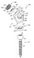
- FIG. 1is an exploded perspective view of a pedicle screw construct in accordance with the present principles for holding a spinal rod relative to a pedicle screw in a spine fixation system;
- FIG. 2is a sectional view of the locking sleeve of the pedicle screw construct of FIG. 1 ;
- FIG. 3is a bottom view of the retaining collar of the pedicle screw construct of FIG. 1 ;
- FIG. 4is a sectional view of the pedicle screw construct of FIG. 1 assembled onto the pedicle screw, taken along line 4 - 4 thereof;
- FIG. 5is another sectional view of the pedicle screw construct of FIG. 1 assembled onto the pedicle screw, taken along line 3 - 3 thereof;
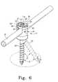
- FIG. 6is a perspective view of the pedicle screw construct of FIG. 1 assembled onto a pedicle screw and holding a spinal rod relative thereto, the pedicle screw illustrated in two positions relative to the head of the pedicle screw construct illustrating the limits of the range of angular orientations of the pedicle screw relative to the head of the pedicle screw construct;
- FIG. 7is a perspective view of another embodiment of a head for a pedicle screw construct in accordance with the principles of the subject invention.
- FIG. 8is a perspective view of the pedicle screw construct head of FIG. 5 relative to a pedicle screw illustrating the limits of the range of angular orientations of the pedicle screw relative to the pedicle screw construct head;
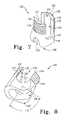
- FIG. 9is a top perspective view of another embodiment of a head for a pedicle screw construct in accordance with the principles of the subject invention.
- FIG. 10is a bottom perspective view of the pedicle screw construct head of FIG. 9 ;
- FIG. 11is a perspective view of a holding collar for a pedicle screw construct utilizing the pedicle screw construct head of FIGS. 9 and 10 ;
- FIG. 12is a perspective view of a pedicle screw construct utilizing the head of FIGS. 9 and 10 along with the collar of FIG. 11 assembled onto a pedicle screw and holding a spinal rod;
- FIG. 13is an enlarged portion of the pedicle screw assembly of FIG. 12 in sectional view
- FIG. 14is an exploded perspective view of another embodiment of a pedicle screw construct in accordance with the present principles for holding a spinal rod relative to a pedicle screw in a spine fixation system;
- FIG. 15is a side view of the pedicle screw construct of FIG. 14 assembled onto the pedicle screw;
- FIG. 16is an end view of the pedicle screw construct of FIG. 14 assembled onto the pedicle screw;
- FIG. 17is a sectional view of the assembled pedicle screw construct of FIG. 16 taken along line 17 - 17 thereof;
- FIG. 18is a top view of the assembled pedicle screw construct of FIG. 16 ;
- FIG. 19is a perspective view of the pedicle screw construct of FIGS. 14-18 shown receiving a spinal rod;
- FIG. 20is the perspective view of FIG. 19 illustrating the manner of loading the spinal rod
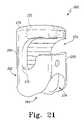
- FIG. 21is a perspective view of another embodiment of a pedicle screw construct head in accordance with the present principles.
- FIG. 22is a front view of an assembled pedicle screw construct utilizing the head of FIG. 21 shown in receipt of a spinal rod before loading thereof;
- FIG. 23is a sectional view of FIG. 22 taken along line 23 - 23 thereof, the pedicle screw of which is shown in various angular orientations relative to the head illustrating the range of angular orientations of the pedicle screw relative to the head in accordance with the principles of the present invention.
- FIG. 1there is depicted an exploded view of an embodiment of a spinal rod fixation device, construct or assembly, generally designated 30 .
- the spinal rod fixation device 30is used as a component in a spinal rod type spine fixation system or assembly.
- the spinal rod fixation device 30consisting of a coupling device, construct or assembly 31 and a pedicle screw 32 , is used to attach or fix a section of a spinal rod (not shown) of the spine fixation assembly relative to a vertebrae of the spine.
- the pedicle screw 32is configured, adapted and/or operable to be attached to a vertebra in a known manner, while the coupling construct 31 receives and fixes, retains or holds the section of the spinal rod (the spinal rod is fixed to the coupling construct).
- the coupling construct 31is movably positionable relative to the pedicle screw 32 as further described herein.
- the coupling construct 31may also be termed a pedicle screw construct, pedicle screw coupling device, or the like.
- the coupling construct 31includes a head 34 , a sleeve 36 , a collar 38 and a fixation element 40 .
- the head 34is configured, adapted and/or operable for reception and retention onto the head 42 of the pedicle screw 32 and to be fixedly, but releasably, angularly oriented with respect to a longitudinal axis of the pedicle screw 32 (e.g. the shank 42 of the pedicle screw 32 ).
- the head 34is further configured, adapted and/or operable for releasable retention or holding of a spinal rod.
- the coupling construct 31is received onto the pedicle screw head 44 and is releasably fixable (positioned) relative thereto within a range of angular orientations.
- the fixing, retaining or holding of the spinal rod to the coupling device 31does not fix the angular orientation of the coupling device 31 relative to the pedicle screw head 44 .
- the angular orientation of the head 34 and pedicle screw 32is releasably fixed independent of the releasable affixation of the spinal rod to the head 34 .
- the angular orientation of the head relative to the pedicle screwis selected and fixed while the spinal rod is received in the head but not fixed thereto.
- the spinal rodis then releasably affixed to the head after the angular positioning of the head/pedicle screw.
- the head 34 of the coupling construct 31is characterized by a body 48 having an axial bore 50 therethrough that defines a first end or opening 51 and a second end or opening 52 .
- the body 48is generally cylindrical or tubular shaped with a slight narrowing on the middle outside of the body 48 .
- the bore 50is sized such that at the first end 51 , a pedicle screw shank and head may easily pass.
- the bore 50is sized such that at the second end 52 the pedicle screw shank may pass, but the pedicle screw head will not.
- a radially inward slope 68is provided at the second end 52 for capturing the pedicle screw head but allow for rotational and angular movement of the head 34 on the pedicle screw head. This allows the angular orientation of the head 34 to be changed relative to the pedicle screw.
- a slot 58is formed in the body 48 having an axis that is essentially perpendicular to the bore 50 .
- the slot 58extends through both sides of the body 48 to define a generally U-shaped channel therebetween and a seat or seating surface 60 on one side of the body 48 and a seat or seating surface 61 on another side of the body 48 .
- the slot 58is sized to receive a spinal rod.
- the spinal rodis retained against the seats 60 , 61 when affixed to the head 34 as described herein.
- the bore 50 and slot 58define first and second walls 52 and 54 that extend from the end 52 .
- the walls 52 and 54are generally arcuate shaped and have a height sufficient to extend over a spinal rod and receive the collar 38 and the fixation device 40 .
- each wall 52 and 54includes a respective groove or slot 64 and 66 .
- Each slot 64 , 66extends or begins (provides an opening) at opposite (180°) sides of the respective wall 52 , 54 and extends a radial distance about the wall 52 , 54 .
- the slots 64 , 66do not extend to the other side of the respective wall 52 , 54 .
- Each slotis adapted to receive a flange of the collar 38 .
- the body 48includes first notch 65 on the inside periphery of the wall 54 , and a second notch 67 on the insider periphery of the wall 52 .
- the notches 65 , 67are sized and/or configured to receive a detent of the collar 38 .
- the sleeve 36 or taper lock element of the coupling construct 31is adapted, configured and/or operable to be received in the head 34 and to interact with the pedicle screw head and collar 38 for providing fixation of an angular orientation or position of the head 34 (coupling construct 31 ) relative or with respect to the associated pedicle screw.
- the sleeve 36is characterized by a body 70 having an axial bore 72 therethrough that defines a first end or opening 73 and a second end or opening 74 .
- the body 70is generally cylindrical or tubular shaped.
- a slot 80is formed in the body 70 having an axis that is essentially perpendicular to the bore 72 .
- the slot 80extends through both sides of the body 70 to define a generally U-shaped channel therebetween and a seat or seating surface 81 on one side of the body 70 and a seat or seating surface 82 on another side of the body 70 .
- the slot 80is sized to receive a spinal rod.
- the spinal rodis retained against the seats 81 , 82 when affixed to the coupling construct 31 as described herein.
- the bore 72 and slot 80define first and second walls 76 and 78 that extend from the end 74 .
- the walls 76 and 78are generally arcuate shaped and have a height sufficient to extend over a spinal rod and be abutted by the collar 38 during angular position fixation of the coupling construct 31 to the pedicle screw.
- FIG. 2a sectional view of the sleeve 36 is shown.
- the bore 72is defined in the body 70 such that the inner side wall 84 of the wall 76 is angled or tapered as is the inner side wall 86 of the wall 78 .
- the upper ends 77 and 79 of the end 73 (walls 76 and 78 )are thus thicker than the ends 85 and 87 of the end 74 (walls 76 and 78 ).
- pressure and this processfixes or wedges the construct 31 relative to the screw 32 .
- the collar 38 of the coupling construct 31is adapted, configured and/or operable to be releasably lockingly received in the head 34 and provide a means or manner in which the angular position or orientation of the coupling construct 31 relative to the pedicle screw on which it is coupled.
- the collar 38has a body 92 of a generally annular or ring shape.
- the body 92defines a first or upper annular side or surface 93 .
- the inner surface 94 of the annular body 92is threaded to receive a like threaded component or element (e.g. the fixation element 40 ).
- Two cutouts or notches 96 and 97are provided in surface 93 that are sized to receive an insertion tool for rotating the collar 38 into position relative to the head 34 .
- the body 92includes two elongated flanges 100 , 101 disposed on the annular outer periphery of the body 92 , preferably opposite one another.
- the flanges 100 , 101are sized to be received in slots 64 and 66 of the head and are thus configured and/or sized accordingly.
- two detents 98 and 99are disposed on the upper rim of the surface 93 .
- the detents 98 , 99are sized to be received in the notches 65 , 67 of the head when the collar 38 is rotatably received in the head 34 .
- the lower surface 102contacts the sleeve for compression against the pedicle screw head.
- the lower surface 102has a first detent structure 104 having a ramped portion 105 and defining a stop surface 106 , and a second detent structure 108 having a ramped portion 109 and defining a stop surface 110 .
- the detent structures 104 , 108are positioned at an angle ⁇ with respect to a centerline, and adjacent a beginning of a flange 100 , 101 .
- FIGS. 4 and 5show cross sectional views of the coupling construct 31 on the pedicle screw 32 .
- the fixation element 40 of the coupling construct 31is adapted, configured and/or operable to releasably fix a spinal rod to the coupling construct 31 and is received in the threaded opening 94 of the collar 38 .
- the fixation element or set screw 40has a generally annular body 112 having external threads 116 on the outer annular periphery thereof. Additionally, the body 112 includes a configured bore 114 for receiving an insertion tool. Insertion of the fixation element 40 into the collar 38 presses and fixes the spinal rod to the coupling construct 31 independent of the fixation of the orientation of the coupling construct 31 relative to the pedicle screw 32 . Again, this is best illustrated in FIGS. 4 and 5 .
- FIGS. 4 and 5the manner in which the coupling construct 31 is received on a pedicle screw head 44 , receives a spinal rod 25 (shown in dashed line), and allows fixation of the angular orientation of the coupling construct 31 relative to the pedicle screw 32 independent of the fixation of the spinal rod 25 to the coupling construct 31 is best seen.
- FIG. 4shows that the collar body 92 , when inserted into the head 34 , provides downward pressure on the upper ends 77 , 79 of the sleeve walls 76 , 78 . The downward pressure is transmitted to lower ends 85 , 87 that spread slightly due to its taper to bind against the pedicle screw head 44 .
- FIG. 5shows the receipt of the spinal rod 25 within the channels 58 and 80 of the head 34 and the sleeve 36 respectively.
- the rod 25rests upon the seats 60 , 61 of the head 34 and the seats 81 , 82 of the sleeve 36 .
- the seats 60 , 61 , 81 , 82hold the rod 25 above the pedicle screw head 44 .
- the fixation elements 40e.g. set screw
- the set screw 40provides pressure against the rod 25 to fix the rod 25 relative to the coupling construct 31 independent of the coupling head/pedicle screw fixation.
- FIG. 6shows an assembled coupling construct 31 retaining the spinal rod 25 and illustrating the various angular positions or orientations possible between the coupling construct 31 and the pedicle screw 32 .
- the orientation of the pedicle screw 32is shown in various positions relative to the coupling construct 31 for ease of illustration.
- the coupling construct 31is infinitely variable from 0° (i.e. a vertical axis of the coupling construct 31 coaxial with a longitudinal axis of the screw 32 or shaft 42 thereof) up to about 90° (i.e. at an angle ⁇ of about 45° ⁇ 2° from the vertically aligned screw shaft axis and the coupling construct 31 ).
- FIGS. 7 and 8there is depicted two views of another exemplary embodiment of a head or coupling member/element for a spine fixation coupling construct that is generally designated 120 .
- the head 120is fabricated from a suitable surgical material such as a metal, metal alloy, polymer or the like as is the other heads and/or components of the present invention.
- the coupling member 120is characterized by a body 122 that, in one side profile defines a snub toed boot or shoe shape. This, along with an enlarged pedicle screw head reception area or channel 138 allows the construct to rotate approximately ⁇ 10° ( ⁇ a few degrees) to approximately 90° ( ⁇ a few degrees) in one or more planes.
- the body 122has a central bore 124 defining a first end 126 and a second end 128 .
- the first end 126receives a pedicle screw (shank end first) while the second end 128 allows the pedicle screw shank to extend therethrough, but swivelbly retain or hold the pedicle screw head in like manner to the head 34 of the pedicle screw construct 31 .
- the bore 124defines a first wall 132 extending from a lower portion of the body 122 and a second wall 134 extending from the lower portion of the body 122 .
- the walls 132 and 134are arcuate and preferably, but not necessarily, formed as portions of a circle.
- each wall 132 , 134includes respective threading 133 , 135 , while the respective inner surface of each wall 132 , 134 includes respective elongated, arcuate channels 129 , 131 .
- the walls 132 , 134are shaped to form a U-shaped channel 130 therethrough.
- the channel 130is sized to receive a spinal rod therein.
- the channel 130defines seats 136 , 137 that support the spinal rod.
- the pedicle screw head retention end 128 of the head 120includes a cutout portion or notch 138 that intersects with the bore 124 to create a slot, channel, groove or the like at the end 128 .
- the configured channel 138allows the shank of a pedicle screw to swivel through an angle ⁇ defined as between a longitudinal axis of the bore 124 and a perpendicular thereto.
- the head 120is releasably positionable on the pedicle screw head from 0° (wherein the bore 124 is coaxial with the pedicle screw shaft, such as is depicted in FIG.
- the head 120may rotate about the pedicle screw head in an unrestricted manner (360°) regardless of the position of the pedicle screw shaft relative to the axis of the bore 124 .
- the end 128(including slot 138 ) allows the capture of the screw head such that the coupling member 120 may rotate 360° about the head of the bone screw.
- the slot 138allows the articulation of the bone screw from an approximately a ⁇ 10° ( ⁇ a few degrees) position (where a longitudinal axis of the coupling member 120 is coaxial with a longitudinal axis of the bone screw shaft), to a +90° ( ⁇ a few degrees) position and to all continuous angles therebetween.
- FIGS. 9 and 10there is shown two perspective views of an alternative embodiment of a coupling member or head generally designated 140 .
- the coupling head 140retains the ability to allow movement between it and a bone screw in like manner as the coupling head 120 of FIGS. 7 and 8 .
- the coupling member 140incorporates features not present in the coupling member 120 of FIGS. 7 and 8 .
- the coupling member 140has a body 142 that is formed in a generally block rectangular shape, particularly with respect to a longitudinal axis transverse to a bone screw attached thereto and in a 0° orientation.
- the body 142may take on different forms consistent with the principles of the subject invention.
- the body 142defines an elongated channel 144 that is sized to receive a length of a spinal fixation rod.
- the rod channel 144defines rod seats 153 , 154 .
- the rod channel 144is slightly enclosed by an arched portion 148 of the body 142 .
- the arched portion 148axially extends over a bone screw bore 146 in the body 142 and includes a cutout portion 149 to allow for the insertion of a collar (see, e.g.
- FIG. 11and/or a bone screw.
- At least one, and shown here as two, set screw or rod fixation element bores 150 and 152are disposed in the arched portion 148 .
- the sideloads the spinal rod for releasable fixation of the spinal rod to the head 140 .
- Each bore 150 , 152is threaded to receive a threaded set screw (see e.g. element 40 of FIG. 1 ) that releasably retains or affixes the fixation rod therein once the fixation rod is in a proper position.
- the arched portion 148provides an angled or side mount (rather than from the top) for receipt of the spinal rod.
- the opening of head 140is at an approximately 45° offset.
- the bottom 156 of the head 140includes a slot 158 in communication with the bore 146 and configured in like manner to the slot 138 of head 120 . This allows the same freedom of movement for variable angular positioning of the head 120 relative to a received pedicle screw.
- the opening 158is tapered to retain the rounded head of a bone screw and/or collar from exiting from the coupling member 140 .
- an exemplary embodiment of a collar, generally designated 160that may, and preferably but not necessarily is, utilized with the coupling head 140 .
- the collar 160is characterized by a body 162 having a configured bore 168 along an axis of the cylindrical body 162 .
- a first concave surface 164is provided at one end of the body 162 and is shaped as a portion of a cylinder that has a longitudinal axis that is transverse to the axis of the body 162 (and/or bore 168 ).
- the concave surface 164defines first and second ends 172 , 173 .
- a second concave surface 166is provided at another end of the generally cylindrical or tubular body 162 opposite the first concave surface 164 .
- the second concave surface 166is likewise shaped as a portion of a cylinder that has a longitudinal axis that is transverse to the axis of the body 162 (and/or bore 168 ).
- the concave surface 166defines first and second ends 174 , 175 .
- the first and second concave surfaces 164 and 166are disposed at essentially right angles to each other while the ends 172 , 173 and 174 , 175 are opposite one another.
- the first and second concave surfaces 164 , 166provide an hourglass configuration to the collar 160 is cross section.
- the first and second concave surfaces 164 , 166respectively receive the head of a bone screw and a fixation rod for applying a fixation pressure from the rod to the screw.
- FIG. 12there is depicted an exemplary embodiment of a spine fixation construct, utilizing a pedicle screw 32 and the coupling head 140 , holding a spinal rod 170 .
- the pedicle screw 32is positioned in a 0° position as one limit of its pivoting range and shown in dashed lines in a 90° position as the other limit of its pivoting range.
- the coupling member 140may be positioned in the various manners as described for the construct of FIG. 6 .
- the collar 160is not shown.
- FIG. 13depicts a side sectional view of the construct of FIG. 12 , particularly taken along the axis of the pedicle screw shaft 42 .
- the spinal rod 170rests against the surface 164 of the collar body 162 while the pedicle screw head 44 is disposed adjacent the surface and contacted by the sides thereof.
- Loading of the spinal rod 170 by set screws (not shown) through the set screw bores 150 , 152results in pressure upon the collar 166 which forces against the pedicle screw head 44 thereby fixing its position relative to the coupling head 142 .
- the depiction of FIG. 13illustrates the cooperation and/or interaction of the rod 170 , the collar 160 and the head 44 of the screw 32 . It should be appreciated that the various components are not necessarily sized accordingly.
- connecting rod 170is urged downwardly into the socket of the collar body 162 by set screws (not shown) extending through the set screw bores 150 , 152 , the socket collar body presses against the head 44 of the screw 32 . This creates a friction fit to lock the orientation of the coupling head 140 relative to the rod 170 and the screw 32 .
- FIGS. 14-18there is depicted various views of another pedicle screw construct 190 having a coupling construct 191 and a pedicle screw 32 .
- FIG. 14provides an exploded view of the pedicle screw construct 190 having a coupling construct 191 in exploded view for attachment onto the pedicle screw 32 .
- the coupling construct 191includes a head 192 , a sleeve 194 that is received in the head 192 , a rod retention element 196 that is received by the head 192 , and a set screw or fixation element 198 that is also received by the head 192 .
- the head 192 of the coupling construct 191is characterized by a body 200 having a shape that melds at least some of the features of the various coupling heads of the present invention.
- the body 200has a bore 202 for reception of the pedicle screw 32 therethrough and extension of only the shaft 42 thereof through the configured end 204 of the body 200 , the head 44 of the screw 32 being rotationally captured, retained or held by the configured end 204 .
- the configured endas best seen in FIGS. 16 and 17 , is shaped or channeled in like manner to the channels 138 and 158 of the coupling heads 120 and 140 .
- the head 192provides the same rotation and swiveling range of motion as the heads 120 and 140 .
- the body 200further defines a spine rod channel 206 for reception of a spinal rod.
- Rod seats 207 , 208provide support for the rod against the head 192 .
- the bodyalso has a tilted or angled, generally annular top portion 212 having a threaded bore 214 .
- the top portion 212is angled to provide an angled inlet for a spinal rod into the rod channel 206 .
- the top portion 212creates a rod reception inlet that is angled ( ⁇ ) relative to a 0° position. This provides angled loading against the rod by the rod retention element 198 , whose nose 236 as seen in FIG. 15 , cups around and retains a spinal rod.
- the sleeve 194 of the coupling construct 191has a generally cup-shaped body 224 with a saddle-shaped cavity 222 that defines a front side 224 and a rear side 223 having a shaped that mimics the front 210 of the body 200 of the head 192 .
- the body 220provides a seat for a spinal rod and a fixation element for the pedicle screw head 44 .
- the sleeve 194is loaded against the pedicle screw head 44 to fix the position of the construct 191 relative to the pedicle screw 32 .
- the rod retention element 196 of the coupling construct 191is characterized by a body 230 having a generally flat top surface having a hole 232 therein.
- the body 230also defines an arcuate portion 234 and a configured nose or protrusion 236 .
- the nose 236cradles the spinal rod when assembled.
- the set screw or fixation element 198 of the coupling construct 191is characterized by a generally annular or disk shaped body 240 having threading 242 on the external annular periphery of the body 240 .
- the threadingis sized to thread with the threaded bore 214 of the top portion 212 of the head 214 and thus to be inserted therein.
- the fixation element 198further includes a configured socket 244 on a top surface thereof for driving the fixation element 198 , and a boss 246 on a lower surface thereof.
- the boss 246is sized to register with the bore 232 of the rod retention device 196 when assembled (see e.g. FIG. 17 ).
- FIG. 19depicts the coupling construct 191 on the pedicle screw constituting the pedicle screw construct 190 having received a spinal rod 250 .
- the coupling construct 191is shown before fixation of the spinal rod to the coupling head 200 and before fixation of the orientation of the coupling head 200 relative to the screw head 44 .
- FIG. 20depicts the fixation of the spinal rod to the coupling head 200 and the fixation of the coupling head orientation relative to the screw head 44 .
- the set screw 198has been received in the bore of the top portion 212 such that the rod retention element has loaded or moved into pressure engagement with the rod 250 .
- the nose 236can be seen providing configured retention of the rod 250 . It should be appreciated that while the screw is shown in a 0° position, not withstanding rotation of the head 200 relative to the screw, the screw may be positioned from 0° to approximately 90°.
- the coupling head 260is similar to the coupling head 192 of the coupling construct 191 , but rather provides a side or 90° entry into a rod channel 274 .
- the coupling head 260is characterized by a body 262 having a generally tubular shape having a central bore 264 that extends from a configured end 278 (configured for 90°+ screw angulation) to end 272 .
- the bore 264is threaded at end 272 to receive a set screw (e.g. set screw 198 ).
- An elongated neck 262terminates in a rounded top portion 270 .
- the top portion 270is perpendicular to the bore 264 to provide side entry (approximately 90°) for the spinal rod relative to the axis of the bore (0°).
- FIGS. 22 and 23depict the coupling head 260 as a coupling construct and pedicle screw construct releasably fixedly holding or retaining a spinal rod 280 .
- the coupling constructincludes a collar 282 that fits over the pedicle screw head 44 and provides a seat for the rod 280 .
- the collar 282cradles the rod 280 to maintain the rod 280 in place.
- the set screw 288provides pressure against the rod 280 which provides pressure against the collar 282 which provides pressure against the head 44 to releasably fix the rod 280 to the head 262 and the head 262 to the screw 32 .
- the figures showing the pedicle screw in various orientations or positionsillustrates the various orientations (or limits of a continuous range of orientations or positions) the coupling head or construct may assume in accordance with the present principles, since the pedicle screw will be fixed in orientation when implanted into a vertebra. As such, the coupling head or construct moves, pivots or folds with respect to the screw and/or screw shaft (axis). It can thus be understood that the coupling head/coupling head construct pivots or folds downwardly with respect to the pedicle screw shaft/axis.
- the pedicle screw axisWhen implanted, the pedicle screw axis may be deemed a vertical, and therefore the head/construct preferably, but not necessarily, moves from a vertical (0°) or near vertical ( ⁇ 5°) position to a horizontal (45°) or near horizontal ( ⁇ 5°) position.
- the elongated channel, slot or end of the coupling head/coupling head constructis preferably, but not necessarily, oriented substantially perpendicular to the longitudinal axis of a retained spinal rod.
- the arc of movement of the coupling head or constructis along an arc that is perpendicular to the longitudinal axis of the spinal rod. In FIG. 23 , for example, that range or arc of movement is given by ⁇ .
- the present inventionprovides advantages over the teachings of the prior art with respect to pedicle screw construct technology.
- the principles accompanying the present inventionallows the present pedicle screw construct to be used with greater accuracy. This may ultimately increase the efficacy of an established procedure.
- the present pedicle screw constructs and/or coupling constructs used along with a bone screwmay utilize various types of spinal rods such as straight or pre-curved rods may be used.
- the rodmay be bent or curved in one or more locations.
- the subject pedicle screw constructalso has the ability to fold (articulate) from a raised position of approximately ⁇ 10° ( ⁇ 10°) to approximately 90° ⁇ 10°.
- the pedicle screw constructis operative, configured and/or adapted to releasably lock into any articulation angle from the ⁇ 10° ( ⁇ 10°) to approximately 90° ⁇ 10° position.
- the subject pedicle screw constructalso provides 360° rotation of the coupling member with respect to the bone screw thereof.
- the bone screw/coupling memberalso provides at least one other plane of relative motion.
- the headis angled straight up and down relative to the U-channel, the head is then angled parallel (through and to the at least 45° arc) to the horizon (at least perpendicular to the pedicle screw shaft) to receive the set screw. Thereafter, the head is folded over to where the back surface can be horizontal to the horizon in an effort to lock up the system.
- the systemcan be locked in any arcuate and rotational orientation therebetween.
- the subject pedicle screw constructalleviates the need to use multiple systems to produce the same surgical outcome.
- the subject pedicle screw constructprovides the surgeon with greater flexibility during the surgical procedure to adjust pathological anatomy. For example, current systems only allow several degrees of movement from the center to midline area.
- the subject pedicle screw constructallows the surgeon to place the bone screws thereof and then adjust the positioning of the coupling member (stabilization link) intra-operatively without removing the pedicle screws from the pedicle. The net effect is a more forgiving system.
- the subject pedicle screw constructalso provides the surgeon with the ability to adjust the system without disassembly. Particularly, adjustment of a connecting rod or of stack height can be accomplished without disassembling the pedicle construct and/or removing a pedicle screw thereof.
- Current “tulip” designed pedicle screw constructsrequire that during each adjustment the surgeon fully assembly the system. If several adjustments are necessary, the potential to strip out the threads within the tulip are high. If this happens, the entire pedicle screw would need to be removed, in which case the integrity of the whole construct is eroded. This is not the case with the subject pedicle screw construct.
- the subject pedicle screw constructis intended for use with the spine. Particularly, the subject pedicle screw construct is intended (non-exclusively) for patients with the following indications:
- the subject spine fixation systemwhen used for anterolateral non-pedicle screw fixation to the spine, is (non-exclusively) intended for the following indications:
- subject spine fixation system/pedicle screw constructwhen used for posterior non-pedicle screw fixation to the spine, is intended for the following indications:
- the subject spine fixation system or pedicle screw constructdiffers from the prior art in the following ways. Particularly, there is substantially greater surgeon flexibility when placing the bone screws. Due to the wider range of motion offered by the head or coupling member, the pedicle screws can be inserted and placed in the most favorable anatomical position. This can be done because the system is not constrained by the connecting rods or the range of motion offered by the heads.
- the subject systemin one form, is locked into place using a taper lock mechanism which reduces the stress applied to the locking screw mechanism thereof. This is a critical advantage as competing devices are locked into place by utilizing a locking collar, rod and head interface.
- the present spine fixation systemutilizes mechanical advantages of using dual tapered interfaces to apply virtually infinite locking force while minimizing thread shear stresses.
- the subject systemallows for intra-operative adjustment of the system without having to apply the locking mechanism or set screw. Due to the unique design of the head, a connecting rod can be inserted and retained without installing the locking mechanism. This saves time, allows for greater variability with placement and potentially will reduce the need to remove the screw and head due to stripped locking mechanism threads.
- Range of motion of the subject inventionis greater that the prior art.
- the present spine fixation system/pedicle screw constructarticulate from center to midline ⁇ 10°+95°.
- the range of motion cephalad and caudal (superior/inferior)is approximately ⁇ 45°. These ranges of motion surpass all currently available spine fixation systems by at least 10°.
- the screwis loaded into the various connecting components from the top (i.e. top loading). However, while not shown, it is contemplated that the coupling or connection of the screw to the connecting component may be accomplished from the bottom (i.e. bottom loading).
- a bottom loading connecting componentmay allow for greater folding and/or flexibility of the connecting component relative to the screw.
Landscapes
- Health & Medical Sciences (AREA)
- Orthopedic Medicine & Surgery (AREA)
- Life Sciences & Earth Sciences (AREA)
- Neurology (AREA)
- Surgery (AREA)
- Heart & Thoracic Surgery (AREA)
- Engineering & Computer Science (AREA)
- Biomedical Technology (AREA)
- Nuclear Medicine, Radiotherapy & Molecular Imaging (AREA)
- Medical Informatics (AREA)
- Molecular Biology (AREA)
- Animal Behavior & Ethology (AREA)
- General Health & Medical Sciences (AREA)
- Public Health (AREA)
- Veterinary Medicine (AREA)
- Surgical Instruments (AREA)
- Prostheses (AREA)
Abstract
Description
- a. Severe (Grade 3 and 4) Spondylolisthesis at the L5-S1-joint;
- b. Patients receiving fusion using autogenous bone graft only;
- c. Patients who are having the device fixed or attached to the lumbar and sacral spine (L3 and below); and
- d. Patients who are having the device removed after the development of a solid fusion mass.
- a. Degenerative spondylolisthesis with object evidence of neurological impairment;
- b. Fracture;
- c. Dislocation;
- d. Scoliosis;
- e. Kyphosis;
- f. Spinal tumor; and
- g. Previously failed fusion (pseudoarthrosis).
- a. Degenerative disc disease (as defined as back pain of discogenic origin with degenerative disc confirmed by history and radiographic studies);
- b. Spinal stenosis;
- c. Spondylolisthesis;
- d. Spinal deformities (e.g. scoliosis, kyphosis and/or lordosis);
- e. Pseudoarthrosis;
- f. Tumor;
- g. Trauma (e.g. fracture or dislocation); and
- h. Previous failed fusion.
Claims (14)
Priority Applications (5)
| Application Number | Priority Date | Filing Date | Title |
|---|---|---|---|
| US11/034,300US7678137B2 (en) | 2004-01-13 | 2005-01-12 | Pedicle screw constructs for spine fixation systems |
| AU2005206822AAU2005206822B2 (en) | 2004-01-13 | 2005-01-13 | Pedicle screw constructs for spine fixation systems |
| JP2006549545AJP4621691B2 (en) | 2004-01-13 | 2005-01-13 | Pedicle screw structure for spinal fixation system |
| PCT/US2005/000898WO2005070165A2 (en) | 2004-01-13 | 2005-01-13 | Pedicle screw constructs for spine fixation systems |
| US11/829,814US8092494B2 (en) | 2004-01-13 | 2007-07-27 | Pedicle screw constructs for spine fixation systems |
Applications Claiming Priority (2)
| Application Number | Priority Date | Filing Date | Title |
|---|---|---|---|
| US53631904P | 2004-01-13 | 2004-01-13 | |
| US11/034,300US7678137B2 (en) | 2004-01-13 | 2005-01-12 | Pedicle screw constructs for spine fixation systems |
Related Child Applications (1)
| Application Number | Title | Priority Date | Filing Date |
|---|---|---|---|
| US11/829,814ContinuationUS8092494B2 (en) | 2004-01-13 | 2007-07-27 | Pedicle screw constructs for spine fixation systems |
Publications (2)
| Publication Number | Publication Date |
|---|---|
| US20050187548A1 US20050187548A1 (en) | 2005-08-25 |
| US7678137B2true US7678137B2 (en) | 2010-03-16 |
Family
ID=34863785
Family Applications (2)
| Application Number | Title | Priority Date | Filing Date |
|---|---|---|---|
| US11/034,300Active2026-03-20US7678137B2 (en) | 2004-01-13 | 2005-01-12 | Pedicle screw constructs for spine fixation systems |
| US11/829,814Active2028-04-26US8092494B2 (en) | 2004-01-13 | 2007-07-27 | Pedicle screw constructs for spine fixation systems |
Family Applications After (1)
| Application Number | Title | Priority Date | Filing Date |
|---|---|---|---|
| US11/829,814Active2028-04-26US8092494B2 (en) | 2004-01-13 | 2007-07-27 | Pedicle screw constructs for spine fixation systems |
Country Status (4)
| Country | Link |
|---|---|
| US (2) | US7678137B2 (en) |
| JP (1) | JP4621691B2 (en) |
| AU (1) | AU2005206822B2 (en) |
| WO (1) | WO2005070165A2 (en) |
Cited By (76)
| Publication number | Priority date | Publication date | Assignee | Title |
|---|---|---|---|---|
| US20040153077A1 (en)* | 2000-11-10 | 2004-08-05 | Lutz Biedermann | Bone screw |
| US20080021473A1 (en)* | 2004-01-13 | 2008-01-24 | Life Spine Llc | Pedicle screw constructs for spine fixation systetms |
| US20080132953A1 (en)* | 2001-09-14 | 2008-06-05 | Stryker Spine | Methods for stabilizing bone using spinal fixation devices |
| US20080177322A1 (en)* | 2006-12-29 | 2008-07-24 | Melissa Davis | Spinal stabilization systems and methods |
| US20080288002A1 (en)* | 2006-12-29 | 2008-11-20 | Abbott Spine Inc. | Spinal Stabilization Systems and Methods |
| US20090254125A1 (en)* | 2008-04-03 | 2009-10-08 | Daniel Predick | Top Loading Polyaxial Spine Screw Assembly With One Step Lockup |
| US20100087874A1 (en)* | 2005-12-21 | 2010-04-08 | Jong Wuk Jang | Pedicle screw |
| US20100262195A1 (en)* | 2005-05-27 | 2010-10-14 | Jackson Roger P | Polyaxial bone screw with shank articulation pressure insert and method |
| US20110160772A1 (en)* | 2009-12-28 | 2011-06-30 | Arcenio Gregory B | Systems and methods for performing spinal fusion |
| US8007518B2 (en) | 2008-02-26 | 2011-08-30 | Spartek Medical, Inc. | Load-sharing component having a deflectable post and method for dynamic stabilization of the spine |
| US8012181B2 (en) | 2008-02-26 | 2011-09-06 | Spartek Medical, Inc. | Modular in-line deflection rod and bone anchor system and method for dynamic stabilization of the spine |
| US8016861B2 (en) | 2008-02-26 | 2011-09-13 | Spartek Medical, Inc. | Versatile polyaxial connector assembly and method for dynamic stabilization of the spine |
| US8021396B2 (en) | 2007-06-05 | 2011-09-20 | Spartek Medical, Inc. | Configurable dynamic spinal rod and method for dynamic stabilization of the spine |
| US8048115B2 (en) | 2007-06-05 | 2011-11-01 | Spartek Medical, Inc. | Surgical tool and method for implantation of a dynamic bone anchor |
| US8057517B2 (en) | 2008-02-26 | 2011-11-15 | Spartek Medical, Inc. | Load-sharing component having a deflectable post and centering spring and method for dynamic stabilization of the spine |
| US8083772B2 (en) | 2007-06-05 | 2011-12-27 | Spartek Medical, Inc. | Dynamic spinal rod assembly and method for dynamic stabilization of the spine |
| US8083775B2 (en) | 2008-02-26 | 2011-12-27 | Spartek Medical, Inc. | Load-sharing bone anchor having a natural center of rotation and method for dynamic stabilization of the spine |
| US8092501B2 (en) | 2007-06-05 | 2012-01-10 | Spartek Medical, Inc. | Dynamic spinal rod and method for dynamic stabilization of the spine |
| US8096996B2 (en) | 2007-03-20 | 2012-01-17 | Exactech, Inc. | Rod reducer |
| US8097024B2 (en) | 2008-02-26 | 2012-01-17 | Spartek Medical, Inc. | Load-sharing bone anchor having a deflectable post and method for stabilization of the spine |
| US8114134B2 (en) | 2007-06-05 | 2012-02-14 | Spartek Medical, Inc. | Spinal prosthesis having a three bar linkage for motion preservation and dynamic stabilization of the spine |
| US8211155B2 (en) | 2008-02-26 | 2012-07-03 | Spartek Medical, Inc. | Load-sharing bone anchor having a durable compliant member and method for dynamic stabilization of the spine |
| US20120185003A1 (en)* | 2010-12-13 | 2012-07-19 | Lutz Biedermann | Bone anchoring device |
| US8226690B2 (en) | 2005-07-22 | 2012-07-24 | The Board Of Trustees Of The Leland Stanford Junior University | Systems and methods for stabilization of bone structures |
| US8257397B2 (en) | 2009-12-02 | 2012-09-04 | Spartek Medical, Inc. | Low profile spinal prosthesis incorporating a bone anchor having a deflectable post and a compound spinal rod |
| US8267969B2 (en) | 2004-10-20 | 2012-09-18 | Exactech, Inc. | Screw systems and methods for use in stabilization of bone structures |
| US8267979B2 (en) | 2008-02-26 | 2012-09-18 | Spartek Medical, Inc. | Load-sharing bone anchor having a deflectable post and axial spring and method for dynamic stabilization of the spine |
| US8317836B2 (en) | 2007-06-05 | 2012-11-27 | Spartek Medical, Inc. | Bone anchor for receiving a rod for stabilization and motion preservation spinal implantation system and method |
| US8333792B2 (en) | 2008-02-26 | 2012-12-18 | Spartek Medical, Inc. | Load-sharing bone anchor having a deflectable post and method for dynamic stabilization of the spine |
| US8337536B2 (en) | 2008-02-26 | 2012-12-25 | Spartek Medical, Inc. | Load-sharing bone anchor having a deflectable post with a compliant ring and method for stabilization of the spine |
| US20130053892A1 (en)* | 2011-08-31 | 2013-02-28 | Depuy Spine, Inc. | System and method for cervical midline fixation |
| US8430916B1 (en) | 2012-02-07 | 2013-04-30 | Spartek Medical, Inc. | Spinal rod connectors, methods of use, and spinal prosthesis incorporating spinal rod connectors |
| US8518085B2 (en) | 2010-06-10 | 2013-08-27 | Spartek Medical, Inc. | Adaptive spinal rod and methods for stabilization of the spine |
| US8523865B2 (en) | 2005-07-22 | 2013-09-03 | Exactech, Inc. | Tissue splitter |
| US8608782B1 (en)* | 2011-02-10 | 2013-12-17 | Robert A. Rovner | Scoliosis de-rotation system and method |
| US20140142640A1 (en)* | 2011-03-09 | 2014-05-22 | Zimmer Spine, Inc. | Polyaxial pedicle screw with increased angulation |
| US8986349B1 (en) | 2009-11-11 | 2015-03-24 | Nuvasive, Inc. | Systems and methods for correcting spinal deformities |
| US9005249B2 (en) | 2011-07-11 | 2015-04-14 | Life Spine, Inc. | Spinal rod connector assembly |
| US9060813B1 (en) | 2008-02-29 | 2015-06-23 | Nuvasive, Inc. | Surgical fixation system and related methods |
| US9084634B1 (en) | 2010-07-09 | 2015-07-21 | Theken Spine, Llc | Uniplanar screw |
| US9131962B2 (en) | 2011-05-24 | 2015-09-15 | Globus Medical, Inc. | Bone screw assembly |
| US9271759B2 (en) | 2012-03-09 | 2016-03-01 | Institute Of Musculoskeletal Science And Education, Ltd. | Pedicle screw assembly with locking cap |
| US9339304B2 (en) | 2011-10-27 | 2016-05-17 | Biedermann Technologies Gmbh & Co. Kg | High angulation polyaxial bone anchoring device |
| US9358122B2 (en) | 2011-01-07 | 2016-06-07 | K2M, Inc. | Interbody spacer |
| US9387013B1 (en) | 2011-03-01 | 2016-07-12 | Nuvasive, Inc. | Posterior cervical fixation system |
| WO2016077621A3 (en)* | 2014-11-13 | 2016-08-18 | Dynamic Spine, Llc | Bone attachment assembly |
| US9707100B2 (en) | 2015-06-25 | 2017-07-18 | Institute for Musculoskeletal Science and Education, Ltd. | Interbody fusion device and system for implantation |
| US9713488B2 (en) | 2008-02-04 | 2017-07-25 | Medos International Sarl | Methods for correction of spinal deformities |
| US9724145B2 (en) | 2013-03-14 | 2017-08-08 | Medos International Sarl | Bone anchor assemblies with multiple component bottom loading bone anchors |
| US9724130B2 (en) | 2013-03-14 | 2017-08-08 | Medos International Sarl | Locking compression members for use with bone anchor assemblies and methods |
| US9763704B2 (en) | 2011-08-31 | 2017-09-19 | DePuy Synthes Products, Inc. | System and method for cervical midline fixation |
| US9775660B2 (en) | 2013-03-14 | 2017-10-03 | DePuy Synthes Products, Inc. | Bottom-loading bone anchor assemblies and methods |
| US9782204B2 (en) | 2012-09-28 | 2017-10-10 | Medos International Sarl | Bone anchor assemblies |
| USD799949S1 (en) | 2007-10-24 | 2017-10-17 | Nuvasive, Inc. | Favored angle screw |
| US9844398B2 (en) | 2012-05-11 | 2017-12-19 | Orthopediatrics Corporation | Surgical connectors and instrumentation |
| US9918747B2 (en) | 2013-03-14 | 2018-03-20 | DePuy Synthes Products, Inc. | Bone anchor assemblies and methods with improved locking |
| US10034691B1 (en) | 2015-12-03 | 2018-07-31 | Nuvasive, Inc. | Bone anchor |
| US10299839B2 (en) | 2003-12-16 | 2019-05-28 | Medos International Sárl | Percutaneous access devices and bone anchor assemblies |
| US10335200B2 (en) | 2007-09-17 | 2019-07-02 | Roger P. Jackson | Pivotal bone anchor assembly with twist-in-place insert having alignment notches |
| US10342582B2 (en) | 2013-03-14 | 2019-07-09 | DePuy Synthes Products, Inc. | Bone anchor assemblies and methods with improved locking |
| US10507043B1 (en) | 2017-10-11 | 2019-12-17 | Seaspine Orthopedics Corporation | Collet for a polyaxial screw assembly |
| US10603083B1 (en) | 2010-07-09 | 2020-03-31 | Theken Spine, Llc | Apparatus and method for limiting a range of angular positions of a screw |
| US10610265B1 (en) | 2017-07-31 | 2020-04-07 | K2M, Inc. | Polyaxial bone screw with increased angulation |
| US11051855B2 (en)* | 2004-04-08 | 2021-07-06 | Globus Medical, Inc. | Polyaxial screw |
| US20210212723A1 (en)* | 2009-05-20 | 2021-07-15 | DePuy Synthes Products, Inc. | Patient-Mounted Retraction |
| US11246627B2 (en) | 2004-10-05 | 2022-02-15 | Roger P. Jackson | Pivotal bone anchor assembly with receiver having threaded lower opening |
| US11419642B2 (en) | 2003-12-16 | 2022-08-23 | Medos International Sarl | Percutaneous access devices and bone anchor assemblies |
| US11534207B2 (en)* | 2019-02-11 | 2022-12-27 | Next Orthosurgical, Inc. | Corrective angle pedicle screw technology |
| EP4212113A1 (en) | 2014-06-25 | 2023-07-19 | Canary Medical Switzerland AG | Devices monitoring spinal implants |
| US20230240724A1 (en)* | 2019-05-22 | 2023-08-03 | Nuvasive, Inc. | Posterior spinal fixation screws |
| US11751918B2 (en)* | 2020-03-12 | 2023-09-12 | Biedermann Technologies Gmbh & Co. Kg | Coupling device for use with a bone anchoring element and bone anchoring device with such a coupling device |
| US11872143B2 (en) | 2016-10-25 | 2024-01-16 | Camber Spine Technologies, LLC | Spinal fusion implant |
| US11877935B2 (en) | 2016-10-18 | 2024-01-23 | Camber Spine Technologies, LLC | Implant with deployable blades |
| US12127766B2 (en) | 2021-03-05 | 2024-10-29 | Medos International Sàrl | Selectively locking polyaxial screw |
| EP4501218A2 (en) | 2014-09-17 | 2025-02-05 | Canary Medical Inc. | Devices, systems and methods for using and monitoring medical devices |
| US12440248B2 (en) | 2022-06-28 | 2025-10-14 | DePuy Synthes Products, Inc. | Minimally invasive instrument set, devices, and related methods |
Families Citing this family (208)
| Publication number | Priority date | Publication date | Assignee | Title |
|---|---|---|---|---|
| US7833250B2 (en) | 2004-11-10 | 2010-11-16 | Jackson Roger P | Polyaxial bone screw with helically wound capture connection |
| US6726689B2 (en) | 2002-09-06 | 2004-04-27 | Roger P. Jackson | Helical interlocking mating guide and advancement structure |
| US8377100B2 (en) | 2000-12-08 | 2013-02-19 | Roger P. Jackson | Closure for open-headed medical implant |
| US10258382B2 (en) | 2007-01-18 | 2019-04-16 | Roger P. Jackson | Rod-cord dynamic connection assemblies with slidable bone anchor attachment members along the cord |
| US7862587B2 (en) | 2004-02-27 | 2011-01-04 | Jackson Roger P | Dynamic stabilization assemblies, tool set and method |
| US20160242816A9 (en)* | 2001-05-09 | 2016-08-25 | Roger P. Jackson | Dynamic spinal stabilization assembly with elastic bumpers and locking limited travel closure mechanisms |
| US8292926B2 (en) | 2005-09-30 | 2012-10-23 | Jackson Roger P | Dynamic stabilization connecting member with elastic core and outer sleeve |
| US10729469B2 (en) | 2006-01-09 | 2020-08-04 | Roger P. Jackson | Flexible spinal stabilization assembly with spacer having off-axis core member |
| US6740086B2 (en) | 2002-04-18 | 2004-05-25 | Spinal Innovations, Llc | Screw and rod fixation assembly and device |
| US11224464B2 (en) | 2002-05-09 | 2022-01-18 | Roger P. Jackson | Threaded closure with inwardly-facing tool engaging concave radiused structures and axial through-aperture |
| US8282673B2 (en) | 2002-09-06 | 2012-10-09 | Jackson Roger P | Anti-splay medical implant closure with multi-surface removal aperture |
| WO2006052796A2 (en) | 2004-11-10 | 2006-05-18 | Jackson Roger P | Helical guide and advancement flange with break-off extensions |
| US8257402B2 (en) | 2002-09-06 | 2012-09-04 | Jackson Roger P | Closure for rod receiving orthopedic implant having left handed thread removal |
| US8876868B2 (en) | 2002-09-06 | 2014-11-04 | Roger P. Jackson | Helical guide and advancement flange with radially loaded lip |
| US8162989B2 (en)* | 2002-11-04 | 2012-04-24 | Altus Partners, Llc | Orthopedic rod system |
| US7141051B2 (en) | 2003-02-05 | 2006-11-28 | Pioneer Laboratories, Inc. | Low profile spinal fixation system |
| US7621918B2 (en) | 2004-11-23 | 2009-11-24 | Jackson Roger P | Spinal fixation tool set and method |
| US6716214B1 (en) | 2003-06-18 | 2004-04-06 | Roger P. Jackson | Polyaxial bone screw with spline capture connection |
| US7377923B2 (en) | 2003-05-22 | 2008-05-27 | Alphatec Spine, Inc. | Variable angle spinal screw assembly |
| US8926670B2 (en) | 2003-06-18 | 2015-01-06 | Roger P. Jackson | Polyaxial bone screw assembly |
| US8092500B2 (en) | 2007-05-01 | 2012-01-10 | Jackson Roger P | Dynamic stabilization connecting member with floating core, compression spacer and over-mold |
| US20100211114A1 (en)* | 2003-06-18 | 2010-08-19 | Jackson Roger P | Polyaxial bone anchor with shelf capture connection |
| US8398682B2 (en) | 2003-06-18 | 2013-03-19 | Roger P. Jackson | Polyaxial bone screw assembly |
| US8377102B2 (en) | 2003-06-18 | 2013-02-19 | Roger P. Jackson | Polyaxial bone anchor with spline capture connection and lower pressure insert |
| US7766915B2 (en) | 2004-02-27 | 2010-08-03 | Jackson Roger P | Dynamic fixation assemblies with inner core and outer coil-like member |
| US8366753B2 (en) | 2003-06-18 | 2013-02-05 | Jackson Roger P | Polyaxial bone screw assembly with fixed retaining structure |
| US8257398B2 (en) | 2003-06-18 | 2012-09-04 | Jackson Roger P | Polyaxial bone screw with cam capture |
| US8137386B2 (en) | 2003-08-28 | 2012-03-20 | Jackson Roger P | Polyaxial bone screw apparatus |
| US7967850B2 (en) | 2003-06-18 | 2011-06-28 | Jackson Roger P | Polyaxial bone anchor with helical capture connection, insert and dual locking assembly |
| US7527638B2 (en) | 2003-12-16 | 2009-05-05 | Depuy Spine, Inc. | Methods and devices for minimally invasive spinal fixation element placement |
| JP2007525274A (en) | 2004-02-27 | 2007-09-06 | ロジャー・ピー・ジャクソン | Orthopedic implant rod reduction instrument set and method |
| US8152810B2 (en) | 2004-11-23 | 2012-04-10 | Jackson Roger P | Spinal fixation tool set and method |
| US11241261B2 (en) | 2005-09-30 | 2022-02-08 | Roger P Jackson | Apparatus and method for soft spinal stabilization using a tensionable cord and releasable end structure |
| US7160300B2 (en) | 2004-02-27 | 2007-01-09 | Jackson Roger P | Orthopedic implant rod reduction tool set and method |
| US7766945B2 (en) | 2004-08-10 | 2010-08-03 | Lanx, Inc. | Screw and rod fixation system |
| DE202004020396U1 (en) | 2004-08-12 | 2005-07-07 | Columbus Trading-Partners Pos und Brendel GbR (vertretungsberechtigte Gesellschafter Karin Brendel, 95503 Hummeltal und Bohumila Pos, 95445 Bayreuth) | Child seat for motor vehicles |
| US7651502B2 (en) | 2004-09-24 | 2010-01-26 | Jackson Roger P | Spinal fixation tool set and method for rod reduction and fastener insertion |
| US8162985B2 (en) | 2004-10-20 | 2012-04-24 | The Board Of Trustees Of The Leland Stanford Junior University | Systems and methods for posterior dynamic stabilization of the spine |
| US7935134B2 (en)* | 2004-10-20 | 2011-05-03 | Exactech, Inc. | Systems and methods for stabilization of bone structures |
| US8025680B2 (en) | 2004-10-20 | 2011-09-27 | Exactech, Inc. | Systems and methods for posterior dynamic stabilization of the spine |
| US7604655B2 (en)* | 2004-10-25 | 2009-10-20 | X-Spine Systems, Inc. | Bone fixation system and method for using the same |
| WO2006047711A2 (en) | 2004-10-25 | 2006-05-04 | Alphaspine, Inc. | Pedicle screw systems and methods |
| WO2006047555A2 (en)* | 2004-10-25 | 2006-05-04 | Alphaspine, Inc. | Bone fixation systems and methods |
| US7691129B2 (en) | 2004-10-27 | 2010-04-06 | Felix Brent A | Spinal stabilizing system |
| US8926672B2 (en) | 2004-11-10 | 2015-01-06 | Roger P. Jackson | Splay control closure for open bone anchor |
| US8444681B2 (en) | 2009-06-15 | 2013-05-21 | Roger P. Jackson | Polyaxial bone anchor with pop-on shank, friction fit retainer and winged insert |
| US8308782B2 (en) | 2004-11-23 | 2012-11-13 | Jackson Roger P | Bone anchors with longitudinal connecting member engaging inserts and closures for fixation and optional angulation |
| WO2006057837A1 (en) | 2004-11-23 | 2006-06-01 | Jackson Roger P | Spinal fixation tool attachment structure |
| US9980753B2 (en) | 2009-06-15 | 2018-05-29 | Roger P Jackson | pivotal anchor with snap-in-place insert having rotation blocking extensions |
| US7875065B2 (en) | 2004-11-23 | 2011-01-25 | Jackson Roger P | Polyaxial bone screw with multi-part shank retainer and pressure insert |
| US9216041B2 (en) | 2009-06-15 | 2015-12-22 | Roger P. Jackson | Spinal connecting members with tensioned cords and rigid sleeves for engaging compression inserts |
| US9168069B2 (en) | 2009-06-15 | 2015-10-27 | Roger P. Jackson | Polyaxial bone anchor with pop-on shank and winged insert with lower skirt for engaging a friction fit retainer |
| WO2006058221A2 (en) | 2004-11-24 | 2006-06-01 | Abdou Samy M | Devices and methods for inter-vertebral orthopedic device placement |
| US7445627B2 (en)* | 2005-01-31 | 2008-11-04 | Alpinespine, Llc | Polyaxial pedicle screw assembly |
| US7901437B2 (en) | 2007-01-26 | 2011-03-08 | Jackson Roger P | Dynamic stabilization member with molded connection |
| US10076361B2 (en) | 2005-02-22 | 2018-09-18 | Roger P. Jackson | Polyaxial bone screw with spherical capture, compression and alignment and retention structures |
| WO2006096381A2 (en) | 2005-03-03 | 2006-09-14 | Accelerated Innovation Llc | Spinal stabilization using bone anchor seat and cross coupling with improved locking feature |
| WO2006096351A1 (en)* | 2005-03-03 | 2006-09-14 | Accelerated Innovation, Llc | Spinal stabilization using bone anchor and anchor seat with tangential locking feature |
| TWI375545B (en) | 2005-04-25 | 2012-11-01 | Synthes Gmbh | Bone anchor with locking cap and method of spinal fixation |
| CA2614898C (en) | 2005-04-27 | 2014-04-22 | Trinity Orthopedics, Llc | Mono-planar pedilcle screw method, system, and kit |
| US20060264252A1 (en)* | 2005-05-23 | 2006-11-23 | White Gehrig H | System and method for providing a host console for use with an electronic card game |
| US7717943B2 (en) | 2005-07-29 | 2010-05-18 | X-Spine Systems, Inc. | Capless multiaxial screw and spinal fixation assembly and method |
| US7955358B2 (en)* | 2005-09-19 | 2011-06-07 | Albert Todd J | Bone screw apparatus, system and method |
| US20080140076A1 (en)* | 2005-09-30 | 2008-06-12 | Jackson Roger P | Dynamic stabilization connecting member with slitted segment and surrounding external elastomer |
| US8105368B2 (en) | 2005-09-30 | 2012-01-31 | Jackson Roger P | Dynamic stabilization connecting member with slitted core and outer sleeve |
| WO2007041702A2 (en)* | 2005-10-04 | 2007-04-12 | Alphaspine, Inc. | Pedicle screw system with provisional locking aspects |
| US8075599B2 (en) | 2005-10-18 | 2011-12-13 | Warsaw Orthopedic, Inc. | Adjustable bone anchor assembly |
| US8002806B2 (en)* | 2005-10-20 | 2011-08-23 | Warsaw Orthopedic, Inc. | Bottom loading multi-axial screw assembly |
| US8097025B2 (en)* | 2005-10-25 | 2012-01-17 | X-Spine Systems, Inc. | Pedicle screw system configured to receive a straight or curved rod |
| US8100946B2 (en)* | 2005-11-21 | 2012-01-24 | Synthes Usa, Llc | Polyaxial bone anchors with increased angulation |
| US20070135817A1 (en)* | 2005-12-08 | 2007-06-14 | Ensign Michael D | Percutaneous screw assembly |
| US7704271B2 (en) | 2005-12-19 | 2010-04-27 | Abdou M Samy | Devices and methods for inter-vertebral orthopedic device placement |
| US20080294198A1 (en)* | 2006-01-09 | 2008-11-27 | Jackson Roger P | Dynamic spinal stabilization assembly with torsion and shear control |
| US20070191839A1 (en)* | 2006-01-27 | 2007-08-16 | Sdgi Holdings, Inc. | Non-locking multi-axial joints in a vertebral implant and methods of use |
| US7833252B2 (en)* | 2006-01-27 | 2010-11-16 | Warsaw Orthopedic, Inc. | Pivoting joints for spinal implants including designed resistance to motion and methods of use |
| US7722652B2 (en)* | 2006-01-27 | 2010-05-25 | Warsaw Orthopedic, Inc. | Pivoting joints for spinal implants including designed resistance to motion and methods of use |
| US8057519B2 (en)* | 2006-01-27 | 2011-11-15 | Warsaw Orthopedic, Inc. | Multi-axial screw assembly |
| US7867257B2 (en)* | 2006-03-20 | 2011-01-11 | Synthes Usa, Llc | Poly-axial bone screw mating seat |
| CA2647026A1 (en)* | 2006-03-22 | 2008-08-28 | Pioneer Surgical Technology, Inc. | Low top bone fixation system and method for using the same |
| WO2007114834A1 (en)* | 2006-04-05 | 2007-10-11 | Dong Myung Jeon | Multi-axial, double locking bone screw assembly |
| DE602006009069D1 (en)* | 2006-04-06 | 2009-10-22 | Biedermann Motech Gmbh | Angled polyaxial bone anchoring device |
| WO2007121271A2 (en) | 2006-04-11 | 2007-10-25 | Synthes (U.S.A) | Minimally invasive fixation system |
| US20070270831A1 (en)* | 2006-05-01 | 2007-11-22 | Sdgi Holdings, Inc. | Bone anchor system utilizing a molded coupling member for coupling a bone anchor to a stabilization member and method therefor |
| US20070270832A1 (en)* | 2006-05-01 | 2007-11-22 | Sdgi Holdings, Inc. | Locking device and method, for use in a bone stabilization system, employing a set screw member and deformable saddle member |
| US7914559B2 (en)* | 2006-05-30 | 2011-03-29 | Warsaw Orthopedic, Inc. | Locking device and method employing a posted member to control positioning of a stabilization member of a bone stabilization system |
| US20080058808A1 (en) | 2006-06-14 | 2008-03-06 | Spartek Medical, Inc. | Implant system and method to treat degenerative disorders of the spine |
| US8062340B2 (en) | 2006-08-16 | 2011-11-22 | Pioneer Surgical Technology, Inc. | Spinal rod anchor device and method |
| EP1891904B1 (en)* | 2006-08-24 | 2013-12-25 | Biedermann Technologies GmbH & Co. KG | Bone anchoring device |
| US8016862B2 (en)* | 2006-09-27 | 2011-09-13 | Innovasis, Inc. | Spinal stabilizing system |
| US8167910B2 (en)* | 2006-10-16 | 2012-05-01 | Innovative Delta Technology Llc | Bone screw and associated assembly and methods of use thereof |
| CA2670988C (en) | 2006-12-08 | 2014-03-25 | Roger P. Jackson | Tool system for dynamic spinal implants |
| US20080154308A1 (en)* | 2006-12-21 | 2008-06-26 | Warsaw Orthopedic, Inc. | Spinal fixation system |
| AU2008206396A1 (en)* | 2007-01-12 | 2008-07-24 | Lanx, Inc. | Bone fastener assembly |
| US9962194B2 (en) | 2007-01-15 | 2018-05-08 | Innovative Delta Technology, Llc | Polyaxial spinal stabilizer connector and methods of use thereof |
| US7794478B2 (en) | 2007-01-15 | 2010-09-14 | Innovative Delta Technology, Llc | Polyaxial cross connector and methods of use thereof |
| US8366745B2 (en) | 2007-05-01 | 2013-02-05 | Jackson Roger P | Dynamic stabilization assembly having pre-compressed spacers with differential displacements |
| US8475498B2 (en) | 2007-01-18 | 2013-07-02 | Roger P. Jackson | Dynamic stabilization connecting member with cord connection |
| US10792074B2 (en) | 2007-01-22 | 2020-10-06 | Roger P. Jackson | Pivotal bone anchor assemly with twist-in-place friction fit insert |
| US8034081B2 (en) | 2007-02-06 | 2011-10-11 | CollabComl, LLC | Interspinous dynamic stabilization implant and method of implanting |
| US8012177B2 (en) | 2007-02-12 | 2011-09-06 | Jackson Roger P | Dynamic stabilization assembly with frusto-conical connection |
| WO2008121343A1 (en)* | 2007-03-30 | 2008-10-09 | Vertiflex, Inc. | Multi-level minimally invasive spinal stabilization system |
| US10383660B2 (en) | 2007-05-01 | 2019-08-20 | Roger P. Jackson | Soft stabilization assemblies with pretensioned cords |
| US8979904B2 (en) | 2007-05-01 | 2015-03-17 | Roger P Jackson | Connecting member with tensioned cord, low profile rigid sleeve and spacer with torsion control |
| US20080275454A1 (en)* | 2007-05-04 | 2008-11-06 | Geibel Paul T | Lumbar pedicular-facet fixation system and instrumentation |
| US8197517B1 (en) | 2007-05-08 | 2012-06-12 | Theken Spine, Llc | Frictional polyaxial screw assembly |
| US7942911B2 (en) | 2007-05-16 | 2011-05-17 | Ortho Innovations, Llc | Polyaxial bone screw |
| US7951173B2 (en) | 2007-05-16 | 2011-05-31 | Ortho Innovations, Llc | Pedicle screw implant system |
| US7947065B2 (en) | 2008-11-14 | 2011-05-24 | Ortho Innovations, Llc | Locking polyaxial ball and socket fastener |
| US8197518B2 (en) | 2007-05-16 | 2012-06-12 | Ortho Innovations, Llc | Thread-thru polyaxial pedicle screw system |
| US7942910B2 (en) | 2007-05-16 | 2011-05-17 | Ortho Innovations, Llc | Polyaxial bone screw |
| US7942909B2 (en) | 2009-08-13 | 2011-05-17 | Ortho Innovations, Llc | Thread-thru polyaxial pedicle screw system |
| CA2690038C (en) | 2007-05-31 | 2012-11-27 | Roger P. Jackson | Dynamic stabilization connecting member with pre-tensioned solid core |
| US8052722B2 (en) | 2007-06-05 | 2011-11-08 | Spartek Medical, Inc. | Dual deflection rod system for a dynamic stabilization and motion preservation spinal implantation system and method |
| US8109970B2 (en) | 2007-06-05 | 2012-02-07 | Spartek Medical, Inc. | Deflection rod system with a deflection contouring shield for a spine implant and method |
| US20080312697A1 (en)* | 2007-06-15 | 2008-12-18 | Robert Reid, Inc. | System and Method for Polyaxially Adjustable Bone Anchorage |
| US20090005815A1 (en)* | 2007-06-28 | 2009-01-01 | Scott Ely | Dynamic stabilization system |
| US9439681B2 (en) | 2007-07-20 | 2016-09-13 | DePuy Synthes Products, Inc. | Polyaxial bone fixation element |
| DE602007007466D1 (en)* | 2007-07-20 | 2010-08-12 | Biedermann Motech Gmbh | Bone anchoring device |
| WO2009029928A1 (en)* | 2007-08-31 | 2009-03-05 | University Of South Florida | Translational manipulation polyaxial screw head |
| US20090069852A1 (en)* | 2007-09-06 | 2009-03-12 | Warsaw Orthopedic, Inc. | Multi-Axial Bone Anchor Assembly |
| US8911477B2 (en) | 2007-10-23 | 2014-12-16 | Roger P. Jackson | Dynamic stabilization member with end plate support and cable core extension |
| US8398683B2 (en)* | 2007-10-23 | 2013-03-19 | Pioneer Surgical Technology, Inc. | Rod coupling assembly and methods for bone fixation |
| JP5651472B2 (en)* | 2007-10-23 | 2015-01-14 | ケー2エム, インコーポレイテッド | Posterior pedicle screw with taper lock |
| US9345517B2 (en)* | 2008-02-02 | 2016-05-24 | Globus Medical, Inc. | Pedicle screw having a removable rod coupling |
| WO2009097623A2 (en)* | 2008-02-02 | 2009-08-06 | Texas Scottish Rite Hospital For Children | Pedicle screw |
| US20090254097A1 (en)* | 2008-04-04 | 2009-10-08 | Isaacs Robert E | System and device for designing and forming a surgical implant |
| US8549888B2 (en) | 2008-04-04 | 2013-10-08 | Nuvasive, Inc. | System and device for designing and forming a surgical implant |
| US20090259254A1 (en)* | 2008-04-15 | 2009-10-15 | Madhavan Pisharodi | Apparatus ans method for aligning and/or stabilizing the spine |
| US8551144B2 (en)* | 2008-04-22 | 2013-10-08 | Collab Comlo, LLC | Bone plate system configurable as static or dynamic implant |
| WO2009155523A1 (en)* | 2008-06-19 | 2009-12-23 | Life Spine, Inc. | Spinal rod connectors configured to retain spinal rods of varying diameters |
| AU2010260521C1 (en) | 2008-08-01 | 2013-08-01 | Roger P. Jackson | Longitudinal connecting member with sleeved tensioned cords |
| JP5815407B2 (en) | 2008-09-12 | 2015-11-17 | ジンテス ゲゼルシャフト ミット ベシュレンクテル ハフツング | Spinal stabilization and guided fixation system |
| KR20110081208A (en) | 2008-09-29 | 2011-07-13 | 신세스 게엠바하 | Multi-Axis Bottom-Loading Screw and Rod Assemblies |
| US20100087873A1 (en)* | 2008-10-06 | 2010-04-08 | Warsaw Orthopedics, Inc. | Surgical Connectors for Attaching an Elongated Member to a Bone |
| US8506601B2 (en)* | 2008-10-14 | 2013-08-13 | Pioneer Surgical Technology, Inc. | Low profile dual locking fixation system and offset anchor member |
| CA2742399A1 (en) | 2008-11-03 | 2010-06-03 | Dustin M. Harvey | Uni-planar bone fixation assembly |
| US8864773B2 (en) | 2009-01-14 | 2014-10-21 | Globus Medical, Inc. | Devices and methods for treating vertebral fractures |
| US8636778B2 (en)* | 2009-02-11 | 2014-01-28 | Pioneer Surgical Technology, Inc. | Wide angulation coupling members for bone fixation system |
| US8998961B1 (en) | 2009-02-26 | 2015-04-07 | Lanx, Inc. | Spinal rod connector and methods |
| KR20120013312A (en) | 2009-04-15 | 2012-02-14 | 신세스 게엠바하 | Orthodontic Connectors for Spinal Structures |
| US20100298884A1 (en)* | 2009-05-21 | 2010-11-25 | Custom Spine, Inc. | Polyaxial Auxiliary Connector |
| US8652176B2 (en)* | 2009-05-29 | 2014-02-18 | Custom Spine, Inc. | Polyaxial screw connection assembly |
| CN103826560A (en) | 2009-06-15 | 2014-05-28 | 罗杰.P.杰克逊 | Polyaxial Bone Anchor with Socket Stem and Winged Inserts with Friction Fit Compression Collars |
| US9668771B2 (en) | 2009-06-15 | 2017-06-06 | Roger P Jackson | Soft stabilization assemblies with off-set connector |
| US11229457B2 (en) | 2009-06-15 | 2022-01-25 | Roger P. Jackson | Pivotal bone anchor assembly with insert tool deployment |
| US8998959B2 (en) | 2009-06-15 | 2015-04-07 | Roger P Jackson | Polyaxial bone anchors with pop-on shank, fully constrained friction fit retainer and lock and release insert |
| CA2764841A1 (en) | 2009-06-17 | 2010-12-23 | Synthes Usa, Llc | Revision connector for spinal constructs |
| USD746461S1 (en) | 2009-06-19 | 2015-12-29 | Life Spine, Inc. | Spinal rod connector |
| US8657856B2 (en) | 2009-08-28 | 2014-02-25 | Pioneer Surgical Technology, Inc. | Size transition spinal rod |
| EP2485654B1 (en) | 2009-10-05 | 2021-05-05 | Jackson P. Roger | Polyaxial bone anchor with non-pivotable retainer and pop-on shank, some with friction fit |
| US8795337B2 (en)* | 2009-10-30 | 2014-08-05 | Warsaw Orthopedic, Inc. | Apparatus for implementing a spinal fixation system with supplemental fixation |
| US20110106173A1 (en)* | 2009-10-30 | 2011-05-05 | Warsaw Orthopedic, Inc. | Anchor Assembly With Directionally Controlled Saddle Adjustment And Transversely Adjustable Receiver |
| US8298275B2 (en)* | 2009-10-30 | 2012-10-30 | Warsaw Orthopedic, Inc. | Direct control spinal implant |
| US8430917B2 (en)* | 2009-10-30 | 2013-04-30 | Warsaw Orthopedic, Inc. | Bone engaging implant with adjustment saddle |
| US20110106180A1 (en)* | 2009-10-30 | 2011-05-05 | Warsaw Orthopedic, Inc. | Implants With Adjustable Saddles |
| US20110106181A1 (en)* | 2009-10-30 | 2011-05-05 | Warsaw Orthopedic, Inc. | Adjustable saddle for a bone anchor |
| US9044272B2 (en) | 2009-11-09 | 2015-06-02 | Ebi, Llc | Multiplanar bone anchor system |
| US8764806B2 (en) | 2009-12-07 | 2014-07-01 | Samy Abdou | Devices and methods for minimally invasive spinal stabilization and instrumentation |
| US8535318B2 (en) | 2010-04-23 | 2013-09-17 | DePuy Synthes Products, LLC | Minimally invasive instrument set, devices and related methods |
| US12383311B2 (en) | 2010-05-14 | 2025-08-12 | Roger P. Jackson | Pivotal bone anchor assembly and method for use thereof |
| US8641717B2 (en) | 2010-07-01 | 2014-02-04 | DePuy Synthes Products, LLC | Guidewire insertion methods and devices |
| WO2012030712A1 (en) | 2010-08-30 | 2012-03-08 | Zimmer Spine, Inc. | Polyaxial pedicle screw |
| AU2011299558A1 (en) | 2010-09-08 | 2013-05-02 | Roger P. Jackson | Dynamic stabilization members with elastic and inelastic sections |
| AU2011324058A1 (en) | 2010-11-02 | 2013-06-20 | Roger P. Jackson | Polyaxial bone anchor with pop-on shank and pivotable retainer |
| DE102010060555A1 (en)* | 2010-11-15 | 2012-05-16 | Ulrich Gmbh & Co. Kg | pedicle screw |
| US9044274B2 (en) | 2010-12-01 | 2015-06-02 | Amendia, Inc. | Bone screw system |
| WO2012106014A1 (en) | 2011-02-02 | 2012-08-09 | Colorado State University Research Foundation | Interspinous spacer devices for dynamic stabilization of degraded spinal segments |
| US9480510B2 (en) | 2011-03-23 | 2016-11-01 | Spinecraft, LLC | Devices, systems and methods of attaching same to the spine |
| JP5865479B2 (en) | 2011-03-24 | 2016-02-17 | ロジャー・ピー・ジャクソン | Multiaxial bone anchor with compound joint and pop-mounted shank |
| CN103717159B (en) | 2011-05-27 | 2016-08-17 | 新特斯有限责任公司 | Minimally Invasive Spinal Fixation System Including Vertebral Alignment Features |
| US11076887B2 (en)* | 2011-07-15 | 2021-08-03 | Globus Medical, Inc. | Orthopedic fixation devices and methods of installation thereof |
| US9655655B2 (en)* | 2011-08-16 | 2017-05-23 | Aesculap Implant Systems, Llc | Two step locking screw assembly |
| US8845728B1 (en) | 2011-09-23 | 2014-09-30 | Samy Abdou | Spinal fixation devices and methods of use |
| DE102011054203A1 (en)* | 2011-10-05 | 2013-04-11 | Aesculap Ag | Readjustable polyaxial pedicle screw |
| US8911479B2 (en) | 2012-01-10 | 2014-12-16 | Roger P. Jackson | Multi-start closures for open implants |
| US20130226240A1 (en) | 2012-02-22 | 2013-08-29 | Samy Abdou | Spinous process fixation devices and methods of use |
| ES2549634T3 (en) | 2012-05-31 | 2015-10-30 | Biedermann Technologies Gmbh & Co. Kg | Polyaxial bone anchoring device |
| EP2689734B1 (en) | 2012-07-27 | 2016-09-14 | Biedermann Technologies GmbH & Co. KG | Polyaxial bone anchoring device with enlarged pivot angle |
| US9198767B2 (en) | 2012-08-28 | 2015-12-01 | Samy Abdou | Devices and methods for spinal stabilization and instrumentation |
| US20140091185A1 (en)* | 2012-09-28 | 2014-04-03 | Flexbar Machine Corp. | Field post |
| US9320617B2 (en) | 2012-10-22 | 2016-04-26 | Cogent Spine, LLC | Devices and methods for spinal stabilization and instrumentation |
| US8911478B2 (en) | 2012-11-21 | 2014-12-16 | Roger P. Jackson | Splay control closure for open bone anchor |
| US10058354B2 (en) | 2013-01-28 | 2018-08-28 | Roger P. Jackson | Pivotal bone anchor assembly with frictional shank head seating surfaces |
| US8852239B2 (en) | 2013-02-15 | 2014-10-07 | Roger P Jackson | Sagittal angle screw with integral shank and receiver |
| US20140277159A1 (en) | 2013-03-14 | 2014-09-18 | DePuy Synthes Products, LLC | Bottom-loading bone anchor assemblies |
| US9433445B2 (en) | 2013-03-14 | 2016-09-06 | DePuy Synthes Products, Inc. | Bone anchors and surgical instruments with integrated guide tips |
| US9427276B2 (en) | 2013-09-17 | 2016-08-30 | Gary D Fleischer | Method of changing position of bones |
| US9566092B2 (en) | 2013-10-29 | 2017-02-14 | Roger P. Jackson | Cervical bone anchor with collet retainer and outer locking sleeve |
| US9717533B2 (en) | 2013-12-12 | 2017-08-01 | Roger P. Jackson | Bone anchor closure pivot-splay control flange form guide and advancement structure |
| US9451993B2 (en) | 2014-01-09 | 2016-09-27 | Roger P. Jackson | Bi-radial pop-on cervical bone anchor |
| US10064658B2 (en) | 2014-06-04 | 2018-09-04 | Roger P. Jackson | Polyaxial bone anchor with insert guides |
| US9597119B2 (en) | 2014-06-04 | 2017-03-21 | Roger P. Jackson | Polyaxial bone anchor with polymer sleeve |
| US10543021B2 (en) | 2014-10-21 | 2020-01-28 | Roger P. Jackson | Pivotal bone anchor assembly having an open ring positioner for a retainer |
| US10149702B2 (en) | 2015-01-12 | 2018-12-11 | Imds Llc | Polyaxial screw and rod system |
| US10070928B2 (en)* | 2015-07-01 | 2018-09-11 | Mako Surgical Corp. | Implant placement planning |
| US9968378B1 (en) | 2015-07-22 | 2018-05-15 | University Of South Florida | Adaptation sphere saddle |
| US10857003B1 (en) | 2015-10-14 | 2020-12-08 | Samy Abdou | Devices and methods for vertebral stabilization |
| WO2018039485A1 (en) | 2016-08-24 | 2018-03-01 | Integrity Implants, Inc. | Adjustable bone fixation systems |
| US10744000B1 (en) | 2016-10-25 | 2020-08-18 | Samy Abdou | Devices and methods for vertebral bone realignment |
| US10973648B1 (en) | 2016-10-25 | 2021-04-13 | Samy Abdou | Devices and methods for vertebral bone realignment |
| WO2019023714A1 (en)* | 2017-07-28 | 2019-01-31 | Anza Innovations Inc. | Spinal stabilization system including bottom loading wide angulation polyaxial rod anchor assemblies |
| US11596449B2 (en) | 2018-09-13 | 2023-03-07 | Roger P. Jackson | Pivotal bone anchor assembly with modular receiver and universal shank head |
| US11179248B2 (en) | 2018-10-02 | 2021-11-23 | Samy Abdou | Devices and methods for spinal implantation |
| US11311317B2 (en) | 2019-09-25 | 2022-04-26 | Stelios KOUTSOUMBELIS | Spinal fixation device with rotatable connector |
| US11504163B2 (en)* | 2020-03-31 | 2022-11-22 | Warsaw Orthopedic, Inc. | Pop-on-cap assemblies having opposing splay-resisting features and generally demi-teardrop opposing rotation-preventing/rotation-resisting features for spinal surgery |
| RU203215U9 (en)* | 2020-10-08 | 2021-05-31 | Российская Федерация, от имени которой выступает Министерство здравоохранения Российской Федерации (Минздрав России) | Corrective device for the surgical treatment of congenital kyphoscoliosis of the thoracic and lumbar spine against the background of impaired formation of the vertebrae in children under three years of age |
| US11464545B1 (en)* | 2021-07-02 | 2022-10-11 | Indius Medical Technologies Private Limited | Anti-splay bone anchor |
| CN113827330B (en) | 2021-10-15 | 2024-10-15 | 郝定均 | Internal fixation system for anatomical reduction of vertebral body and bone grafting in vertebral body of spinal fracture |
Citations (73)
| Publication number | Priority date | Publication date | Assignee | Title |
|---|---|---|---|---|
| US5002542A (en) | 1989-10-30 | 1991-03-26 | Synthes U.S.A. | Pedicle screw clamp |
| US5030220A (en) | 1990-03-29 | 1991-07-09 | Advanced Spine Fixation Systems Incorporated | Spine fixation system |
| US5122131A (en) | 1991-03-14 | 1992-06-16 | Tsou Paul M | Orthopaedic device for mechanical coupling to a surgical rod |
| US5222954A (en) | 1991-06-21 | 1993-06-29 | Artifex, Ltd. | Spinal implant system and method for installing the implant |
| US5242445A (en) | 1991-12-05 | 1993-09-07 | Danek Medical, Inc. | Split eyebolt for spinal rod |
| US5246442A (en) | 1991-12-31 | 1993-09-21 | Danek Medical, Inc. | Spinal hook |
| US5281222A (en) | 1992-06-30 | 1994-01-25 | Zimmer, Inc. | Spinal implant system |
| US5282801A (en) | 1993-02-17 | 1994-02-01 | Danek Medical, Inc. | Top tightening clamp assembly for a spinal fixation system |
| US5282862A (en) | 1991-12-03 | 1994-02-01 | Artifex Ltd. | Spinal implant system and a method for installing the implant onto a vertebral column |
| US5344422A (en) | 1989-10-30 | 1994-09-06 | Synthes (U.S.A.) | Pedicular screw clamp |
| US5360431A (en) | 1990-04-26 | 1994-11-01 | Cross Medical Products | Transpedicular screw system and method of use |
| US5403316A (en) | 1993-12-02 | 1995-04-04 | Danek Medical, Inc. | Triangular construct for spinal fixation |
| US5423818A (en) | 1993-02-17 | 1995-06-13 | Danek Medical, Inc. | Clamp for attaching a vertebral fixation element to a spinal rod |
| US5437670A (en) | 1993-08-19 | 1995-08-01 | Danek Medical, Inc. | Attachment plate for top-tightening clamp assembly in a spinal fixation system |
| US5437669A (en) | 1993-08-12 | 1995-08-01 | Amei Technologies Inc. | Spinal fixation systems with bifurcated connectors |
| US5466237A (en) | 1993-11-19 | 1995-11-14 | Cross Medical Products, Inc. | Variable locking stabilizer anchor seat and screw |
| US5474551A (en) | 1994-11-18 | 1995-12-12 | Smith & Nephew Richards, Inc. | Universal coupler for spinal fixation |
| US5496321A (en) | 1993-11-19 | 1996-03-05 | Cross Medical Products, Inc. | Rod anchor seat having a sliding interlocking rod connector |
| US5520690A (en) | 1995-04-13 | 1996-05-28 | Errico; Joseph P. | Anterior spinal polyaxial locking screw plate assembly |
| US5527314A (en) | 1993-01-04 | 1996-06-18 | Danek Medical, Inc. | Spinal fixation system |
| US5562661A (en) | 1995-03-16 | 1996-10-08 | Alphatec Manufacturing Incorporated | Top tightening bone fixation apparatus |
| US5575792A (en) | 1995-07-14 | 1996-11-19 | Fastenetix, L.L.C. | Extending hook and polyaxial coupling element device for use with top loading rod fixation devices |
| US5578033A (en) | 1995-07-13 | 1996-11-26 | Fastenetix, L.L.C. | Advanced polyaxial locking hook and coupling element device for use with side loading rod fixation devices |
| US5584834A (en) | 1995-07-13 | 1996-12-17 | Fastenetix, L.L.C. | Polyaxial locking screw and coupling element assembly for use with side loading rod fixation apparatus |
| US5609593A (en) | 1995-07-13 | 1997-03-11 | Fastenetix, Llc | Advanced polyaxial locking hook and coupling element device for use with top loading rod fixation devices |
| US5609594A (en) | 1995-07-13 | 1997-03-11 | Fastenetix Llc | Extending hook and polyaxial coupling element device for use with side loading road fixation devices |
| US5669911A (en) | 1995-04-13 | 1997-09-23 | Fastenetix, L.L.C. | Polyaxial pedicle screw |
| US5713904A (en) | 1997-02-12 | 1998-02-03 | Third Millennium Engineering, Llc | Selectively expandable sacral fixation screw-sleeve device |
| US5733285A (en) | 1995-07-13 | 1998-03-31 | Fastenetix, Llc | Polyaxial locking mechanism |
| US5752957A (en) | 1997-02-12 | 1998-05-19 | Third Millennium Engineering, Llc | Polyaxial mechanism for use with orthopaedic implant devices |
| US5776135A (en) | 1996-12-23 | 1998-07-07 | Third Millennium Engineering, Llc | Side mounted polyaxial pedicle screw |
| US5810819A (en) | 1997-05-15 | 1998-09-22 | Spinal Concepts, Inc. | Polyaxial pedicle screw having a compression locking rod gripping mechanism |
| US5810818A (en) | 1995-10-23 | 1998-09-22 | Fastenetix, Llc | Spinal hook implant having a low blade and S swivel hook |
| US5899904A (en) | 1998-10-19 | 1999-05-04 | Third Milennium Engineering, Llc | Compression locking vertebral body screw, staple, and rod assembly |
| US5899905A (en) | 1998-10-19 | 1999-05-04 | Third Millennium Engineering Llc | Expansion locking vertebral body screw, staple, and rod assembly |
| US5961518A (en) | 1997-05-15 | 1999-10-05 | Spinal Concepts, Inc. | Polyaxial pedicle screw having a through bar clamp locking mechanism |
| US6016727A (en) | 1997-02-28 | 2000-01-25 | Sofamor Danek Properties, Inc. | Recess drive bone screw and cooperable driving tool |
| US6074391A (en) | 1997-06-16 | 2000-06-13 | Howmedica Gmbh | Receiving part for a retaining component of a vertebral column implant |
| US6077262A (en)* | 1993-06-04 | 2000-06-20 | Synthes (U.S.A.) | Posterior spinal implant |
| US6132430A (en) | 1996-10-24 | 2000-10-17 | Spinal Concepts, Inc. | Spinal fixation system |
| US6234705B1 (en) | 1999-04-06 | 2001-05-22 | Synthes (Usa) | Transconnector for coupling spinal rods |
| US6261287B1 (en) | 1992-03-02 | 2001-07-17 | Stryker Trauma Gmbh | Apparatus for bracing vertebrae |
| US6280442B1 (en) | 1999-09-01 | 2001-08-28 | Sdgi Holdings, Inc. | Multi-axial bone screw assembly |
| US6283967B1 (en) | 1999-12-17 | 2001-09-04 | Synthes (U.S.A.) | Transconnector for coupling spinal rods |
| US6302888B1 (en) | 1999-03-19 | 2001-10-16 | Interpore Cross International | Locking dovetail and self-limiting set screw assembly for a spinal stabilization member |
| USRE37665E1 (en) | 1995-04-13 | 2002-04-16 | Fastenetix, Llc | Polyaxial pedicle screw having a threaded and tapered compression locking mechanism |
| US6402749B1 (en) | 1999-04-21 | 2002-06-11 | Sdgi Holdings, Inc. | Variable angle connection assembly for a spinal implant system |
| US20020143341A1 (en) | 2001-03-27 | 2002-10-03 | Lutz Biedermann | Anchoring element |
| US6471703B1 (en) | 1999-04-21 | 2002-10-29 | Sdgi Holdings, Inc. | Variable angle connection assembly for a spinal implant system |
| US20020193794A1 (en) | 2001-06-18 | 2002-12-19 | Taylor Harold Sparr | Connection assembly for spinal implant systems |
| US20030004512A1 (en)* | 2000-09-15 | 2003-01-02 | Farris Robert A. | Posterior fixation system |
| US20030004511A1 (en) | 2001-06-27 | 2003-01-02 | Ferree Bret A. | Polyaxial pedicle screw system |
| US20030055426A1 (en)* | 2001-09-14 | 2003-03-20 | John Carbone | Biased angulation bone fixation assembly |
| US6554834B1 (en) | 1999-10-07 | 2003-04-29 | Stryker Spine | Slotted head pedicle screw assembly |
| US6565565B1 (en)* | 1998-06-17 | 2003-05-20 | Howmedica Osteonics Corp. | Device for securing spinal rods |
| US20030105460A1 (en) | 2000-03-15 | 2003-06-05 | Dennis Crandall | Multidirectional pivoting bone screw and fixation system |
| US20030125741A1 (en)* | 2001-12-28 | 2003-07-03 | Biedermann Motech Gmbh | Locking device for securing a rod-shaped element in a holding element connected to a shank |
| US20030176862A1 (en) | 2000-10-23 | 2003-09-18 | Taylor Harold Sparr | Taper-locked adjustable connector |
| US6626908B2 (en)* | 2000-07-22 | 2003-09-30 | Corin Spinal Systems Limited | Pedicle attachment assembly |
| US6626904B1 (en) | 1999-07-27 | 2003-09-30 | Societe Etudes Et Developpements - Sed | Implantable intervertebral connection device |
| US6673073B1 (en) | 1999-11-29 | 2004-01-06 | Schaefer Bernd | Transverse connector |
| US6676661B1 (en) | 1999-07-23 | 2004-01-13 | Antonio Martin Benlloch | Multiaxial connector for spinal implant |
| US20040013866A1 (en) | 2002-05-30 | 2004-01-22 | Yutaka Sasaki | Moisture-absorbent unit and container |
| US6716214B1 (en) | 2003-06-18 | 2004-04-06 | Roger P. Jackson | Polyaxial bone screw with spline capture connection |
| US6723100B2 (en)* | 2001-07-27 | 2004-04-20 | Biedermann Motech Gmbh | Bone screw and fastening tool for same |
| US6733502B2 (en) | 2002-05-15 | 2004-05-11 | Cross Medical Products, Inc. | Variable locking spinal screw having a knurled collar |
| US20040122425A1 (en) | 2002-09-12 | 2004-06-24 | Showa Ika Kohgyo Co., Ltd. | Rod fixing apparatus for vertebra connecting member |
| US6755830B2 (en) | 2001-07-04 | 2004-06-29 | Sofamor S.N.C. | Connector for a spinal fixation member |
| US20040138662A1 (en) | 2002-10-30 | 2004-07-15 | Landry Michael E. | Spinal stabilization systems and methods |
| US20040153068A1 (en) | 2003-02-05 | 2004-08-05 | Pioneer Laboratories, Inc. | Low profile spinal fixation system |
| US20040186474A1 (en)* | 2002-12-02 | 2004-09-23 | Biedermann Motech Gmbh | Implant having a shaft and a holding element connected therewith for connecting with a rod |
| US20050277931A1 (en) | 2004-06-09 | 2005-12-15 | Spinal Generations, Llc | Spinal fixation system |
| US20080167736A1 (en) | 2007-01-10 | 2008-07-10 | Swayze Jeffrey S | Post-sterilization programming of surgical instruments |
Family Cites Families (153)
| Publication number | Priority date | Publication date | Assignee | Title |
|---|---|---|---|---|
| US2414882A (en)* | 1943-09-24 | 1947-01-28 | Herschel Leiter H | Fracture reduction apparatus |
| US4399814A (en) | 1981-04-27 | 1983-08-23 | Massachusetts Institute Of Technology | Method and apparatus for pressure-coated bones |
| CA1227902A (en)* | 1984-04-02 | 1987-10-13 | Raymond G. Tronzo | Fenestrated hip screw and method of augmented internal fixation |
| US4648388B1 (en)* | 1985-11-01 | 1995-10-31 | Acromed Corp | Apparatus and method for maintaining vertebrae in a desired relationship |
| FI81010C (en) | 1986-09-05 | 1990-09-10 | Biocon Oy | Benomplaceringsimplants |
| US4805602A (en)* | 1986-11-03 | 1989-02-21 | Danninger Medical Technology | Transpedicular screw and rod system |
| US4790297A (en) | 1987-07-24 | 1988-12-13 | Biotechnology, Inc. | Spinal fixation method and system |
| US5234299A (en) | 1987-08-03 | 1993-08-10 | Giannuzzi Louis | Self-drilling anchor |
| CH683963A5 (en) | 1988-06-10 | 1994-06-30 | Synthes Ag | Internal fixation. |
| US5139499A (en) | 1989-02-06 | 1992-08-18 | American Cyanamid Company | Screw and driver |
| CA2035348C (en)* | 1990-02-08 | 2000-05-16 | Jean-Louis Vignaud | Adjustable fastening device with spinal osteosynthesis rods |
| US5092893A (en)* | 1990-09-04 | 1992-03-03 | Smith Thomas E | Human orthopedic vertebra implant |
| US5098435A (en)* | 1990-11-21 | 1992-03-24 | Alphatec Manufacturing Inc. | Cannula |
| US5129899A (en) | 1991-03-27 | 1992-07-14 | Smith & Nephew Richards Inc. | Bone fixation apparatus |
| PT100685A (en) | 1991-07-15 | 1994-05-31 | Danek Group Inc | SPINAL FIXING SYSTEM |
| US5261909A (en) | 1992-02-18 | 1993-11-16 | Danek Medical, Inc. | Variable angle screw for spinal implant system |
| US5171279A (en)* | 1992-03-17 | 1992-12-15 | Danek Medical | Method for subcutaneous suprafascial pedicular internal fixation |
| US6406480B1 (en) | 1992-11-13 | 2002-06-18 | American Med Syst | Bone anchor inserter with retractable shield |
| US5350380A (en) | 1993-01-15 | 1994-09-27 | Depuy Inc. | Method for securing a ligament replacement in a bone |
| US5352226A (en) | 1993-02-08 | 1994-10-04 | Lin Chih I | Side locking system rotatable in all directions for use in spinal surgery |
| CH688222A5 (en)* | 1993-12-07 | 1997-06-30 | Synthes Ag | Bone fixation element. |
| US5611800A (en)* | 1994-02-15 | 1997-03-18 | Alphatec Manufacturing, Inc. | Spinal fixation system |
| FR2718945B1 (en) | 1994-04-25 | 1996-07-05 | Soprane Sa | Device for retaining a connecting rod of a spine fixator on a pedicle screw. |
| DE9409123U1 (en) | 1994-06-04 | 1994-09-01 | Howmedica GmbH, 24232 Schönkirchen | Device for stabilizing or compressing or distracting sections of the spine |
| US5616142A (en)* | 1994-07-20 | 1997-04-01 | Yuan; Hansen A. | Vertebral auxiliary fixation device |
| US5569252A (en) | 1994-09-27 | 1996-10-29 | Justin; Daniel F. | Device for repairing a meniscal tear in a knee and method |
| US6176861B1 (en)* | 1994-10-25 | 2001-01-23 | Sdgi Holdings, Inc. | Modular spinal system |
| US5697932A (en)* | 1994-11-09 | 1997-12-16 | Osteonics Corp. | Bone graft delivery system and method |
| FR2731344B1 (en) | 1995-03-06 | 1997-08-22 | Dimso Sa | SPINAL INSTRUMENTATION ESPECIALLY FOR A ROD |
| DE19509332C1 (en)* | 1995-03-15 | 1996-08-14 | Harms Juergen | Anchoring element |
| US6780186B2 (en)* | 1995-04-13 | 2004-08-24 | Third Millennium Engineering Llc | Anterior cervical plate having polyaxial locking screws and sliding coupling elements |
| US5582612A (en) | 1995-05-01 | 1996-12-10 | Lin; Chih-I | Vertebral fixing and retrieving device having centrally two fixation |
| US5667513A (en) | 1995-06-07 | 1997-09-16 | Smith & Nephew Dyonics Inc. | Soft tissue anchor delivery apparatus |
| US5855285A (en)* | 1995-12-04 | 1999-01-05 | Gene E. Laird | Socket holder system |
| US5649931A (en) | 1996-01-16 | 1997-07-22 | Zimmer, Inc. | Orthopaedic apparatus for driving and/or removing a bone screw |
| US5688275A (en) | 1996-02-09 | 1997-11-18 | Koros; Tibor | Spinal column rod fixation system |
| US5884702A (en) | 1996-03-01 | 1999-03-23 | Smith International, Inc. | Liner assembly and method |
| DE29606468U1 (en) | 1996-04-09 | 1997-08-07 | Waldemar Link GmbH & Co, 22339 Hamburg | Spinal fixator |
| DE19617362C2 (en)* | 1996-04-30 | 1999-06-10 | Harms Juergen | Anchoring element |
| US6111164A (en) | 1996-06-21 | 2000-08-29 | Musculoskeletal Transplant Foundation | Bone graft insert |
| US6319270B1 (en) | 1996-08-05 | 2001-11-20 | Arthrex, Inc. | Headed bioabsorbable tissue anchor |
| US5941885A (en) | 1996-10-08 | 1999-08-24 | Jackson; Roger P. | Tools for use in installing osteosynthesis apparatus utilizing set screw with break-off head |
| EP0934026B1 (en) | 1996-10-24 | 2009-07-15 | Zimmer Spine Austin, Inc | Apparatus for spinal fixation |
| ES2191775T3 (en)* | 1996-12-12 | 2003-09-16 | Synthes Ag | DEVICE FOR CONNECTING A LONGITUDINAL SUPPORT WITH A PEDICULAR SCREW. |
| US5782833A (en)* | 1996-12-20 | 1998-07-21 | Haider; Thomas T. | Pedicle screw system for osteosynthesis |
| US6159210A (en) | 1997-01-14 | 2000-12-12 | Research Corporation Technologies, Inc. | Bone fixation pin with rotary cutting tip |
| US6001098A (en) | 1997-01-17 | 1999-12-14 | Howmedica Gmbh | Connecting element for spinal stabilizing system |
| US6371957B1 (en)* | 1997-01-22 | 2002-04-16 | Synthes (Usa) | Device for connecting a longitudinal bar to a pedicle screw |
| US6139550A (en) | 1997-02-11 | 2000-10-31 | Michelson; Gary K. | Skeletal plating system |
| ES2297092T3 (en)* | 1997-02-11 | 2008-05-01 | Warsaw Orthopedic, Inc. | PREVIOUS CERVICAL PLATE OF UNIQUE BLOCK. |
| FR2761256B1 (en) | 1997-04-01 | 1999-06-11 | Daniel Chopin | RACHIDIAN OSTEOSYNTHESIS INSTRUMENTATION WITH CONNECTING CONNECTOR BETWEEN A VERTEBRAL ROD AND BONE ANCHORING ORGANS |
| US6017345A (en) | 1997-05-09 | 2000-01-25 | Spinal Innovations, L.L.C. | Spinal fixation plate |
| ZA983955B (en) | 1997-05-15 | 2001-08-13 | Sdgi Holdings Inc | Anterior cervical plating system. |
| US6413257B1 (en)* | 1997-05-15 | 2002-07-02 | Surgical Dynamics, Inc. | Clamping connector for spinal fixation systems |
| US6248105B1 (en) | 1997-05-17 | 2001-06-19 | Synthes (U.S.A.) | Device for connecting a longitudinal support with a pedicle screw |
| FR2766353B1 (en) | 1997-07-28 | 1999-11-26 | Dimso Sa | IMPLANT, ESPECIALLY ANTERIOR CERVICAL PLATE |
| US5984925A (en)* | 1997-07-30 | 1999-11-16 | Cross Medical Products, Inc. | Longitudinally adjustable bone plates and method for use thereof |
| US6454769B2 (en) | 1997-08-04 | 2002-09-24 | Spinal Concepts, Inc. | System and method for stabilizing the human spine with a bone plate |
| US5947967A (en) | 1997-10-22 | 1999-09-07 | Sdgt Holdings, Inc. | Variable angle connector |
| EP0923908B1 (en) | 1997-12-17 | 2003-04-23 | Robert Lange | Apparatus for stabilizing certain vertebrae of the spine |
| US5976135A (en) | 1997-12-18 | 1999-11-02 | Sdgi Holdings, Inc. | Lateral connector assembly |
| US6179838B1 (en)* | 1998-02-24 | 2001-01-30 | Daniel Fiz | Bone fixation arrangements and method |
| US6317957B1 (en) | 1998-04-14 | 2001-11-20 | Bucyrus International, Inc. | Method for fabricating an excavator base |
| US5951558A (en) | 1998-04-22 | 1999-09-14 | Fiz; Daniel | Bone fixation device |
| US6533786B1 (en) | 1999-10-13 | 2003-03-18 | Sdgi Holdings, Inc. | Anterior cervical plating system |
| US20040220571A1 (en) | 1998-04-30 | 2004-11-04 | Richard Assaker | Bone plate assembly |
| US6258089B1 (en) | 1998-05-19 | 2001-07-10 | Alphatec Manufacturing, Inc. | Anterior cervical plate and fixation system |
| US6228085B1 (en)* | 1998-07-14 | 2001-05-08 | Theken Surgical Llc | Bone fixation system |
| US6231575B1 (en)* | 1998-08-27 | 2001-05-15 | Martin H. Krag | Spinal column retainer |
| PT1117336E (en) | 1998-09-29 | 2004-10-29 | Synthes Ag | DEVICE FOR CONNECTING A LONGITUDINAL SUPPORT TO A BONUS FIXATION MEANS |
| EP1042989B1 (en) | 1999-04-08 | 2004-03-03 | Orthofix International B.V. | Improved bone screw for use in orthopedic surgery |
| US6210376B1 (en)* | 1999-04-08 | 2001-04-03 | New York University | Cannulated delivery pin |
| US6315779B1 (en) | 1999-04-16 | 2001-11-13 | Sdgi Holdings, Inc. | Multi-axial bone anchor system |
| US6210413B1 (en)* | 1999-04-23 | 2001-04-03 | Sdgi Holdings, Inc. | Connecting apparatus using shape-memory technology |
| EP1187567A4 (en)* | 1999-04-28 | 2002-08-14 | James Frederick Harrington Jr | Modular anterior cervical plate |
| US6096060A (en) | 1999-05-20 | 2000-08-01 | Linvatec Corporation | Bioabsorbable threaded soft tissue anchor system |
| US6254602B1 (en) | 1999-05-28 | 2001-07-03 | Sdgi Holdings, Inc. | Advanced coupling device using shape-memory technology |
| US6048343A (en)* | 1999-06-02 | 2000-04-11 | Mathis; John M. | Bone screw system |
| DE59906133D1 (en) | 1999-08-14 | 2003-07-31 | Aesculap Ag & Co Kg | BONE SCREW |
| EP1080692A1 (en)* | 1999-09-03 | 2001-03-07 | Bone & Joint Research S.A. | Flexible connection for bone anchor means |
| US6224602B1 (en)* | 1999-10-11 | 2001-05-01 | Interpore Cross International | Bone stabilization plate with a secured-locking mechanism for cervical fixation |
| FR2801778B1 (en)* | 1999-12-03 | 2002-02-08 | Spinevision | CONNECTION ASSEMBLY FOR THE FIELD OF RACHIDIAN OSTEOSYNTHESIS |
| US6331179B1 (en) | 2000-01-06 | 2001-12-18 | Spinal Concepts, Inc. | System and method for stabilizing the human spine with a bone plate |
| US6893444B2 (en)* | 2000-02-01 | 2005-05-17 | Hand Innovations, Llc | Bone fracture fixation systems with both multidirectional and unidirectional stabilization pegs |
| US6872209B2 (en)* | 2000-03-15 | 2005-03-29 | Sdgi Holdings, Inc. | Spinal implant connection assembly |
| US6248107B1 (en) | 2000-03-15 | 2001-06-19 | Sdgi Holdings, Inc. | System for reducing the displacement of a vertebra |
| US7056321B2 (en)* | 2000-08-01 | 2006-06-06 | Endius, Incorporated | Method of securing vertebrae |
| JP2004505745A (en) | 2000-08-24 | 2004-02-26 | ジンテーズ アクチエンゲゼルシャフト クール | Device for connecting a bone anchoring element to a longitudinal rod |
| US6620164B2 (en) | 2000-09-22 | 2003-09-16 | Showa Ika Kohgyo Co., Ltd. | Rod for cervical vertebra and connecting system thereof |
| US6626906B1 (en) | 2000-10-23 | 2003-09-30 | Sdgi Holdings, Inc. | Multi-planar adjustable connector |
| US6685705B1 (en)* | 2000-10-23 | 2004-02-03 | Sdgi Holdings, Inc. | Six-axis and seven-axis adjustable connector |
| DE10055888C1 (en)* | 2000-11-10 | 2002-04-25 | Biedermann Motech Gmbh | Bone screw, has connector rod receiving part with unsymmetrically arranged end bores |
| US6503250B2 (en)* | 2000-11-28 | 2003-01-07 | Kamaljit S. Paul | Bone support assembly |
| US7651516B2 (en) | 2000-12-01 | 2010-01-26 | Spinevision S.A. | Connection assembly for the field of spinal osteosynthesis and method for using at least one such assembly |
| US6413259B1 (en) | 2000-12-14 | 2002-07-02 | Blackstone Medical, Inc | Bone plate assembly including a screw retaining member |
| US6648894B2 (en) | 2000-12-21 | 2003-11-18 | Stryker Spine | Bone graft forming guide and method of forming bone grafts |
| US6488681B2 (en)* | 2001-01-05 | 2002-12-03 | Stryker Spine S.A. | Pedicle screw assembly |
| US6402756B1 (en) | 2001-02-15 | 2002-06-11 | Third Millennium Engineering, Llc | Longitudinal plate assembly having an adjustable length |
| US6666867B2 (en) | 2001-02-15 | 2003-12-23 | Fast Enetix, Llc | Longitudinal plate assembly having an adjustable length |
| US6641583B2 (en) | 2001-03-29 | 2003-11-04 | Endius Incorporated | Apparatus for retaining bone portions in a desired spatial relationship |
| FR2823096B1 (en) | 2001-04-06 | 2004-03-19 | Materiel Orthopedique En Abreg | PLATE FOR LTE AND LTE VERTEBRATE OSTEOSYNTHESIS DEVICE, OSTEOSYNTHESIS DEVICE INCLUDING SUCH A PLATE, AND INSTRUMENT FOR LAYING SUCH A PLATE |
| US6599290B2 (en) | 2001-04-17 | 2003-07-29 | Ebi, L.P. | Anterior cervical plating system and associated method |
| ATE382298T1 (en) | 2001-04-24 | 2008-01-15 | Coligne Ag | INSTRUMENTS FOR STABILIZING CERTAIN VERTEBRATES OF THE SPINE |
| CA2443429C (en) | 2001-06-04 | 2010-08-10 | Gary Karlin Michelson | Anterior cervical plate system having vertebral body engaging anchors, connecting plate, and method for installation thereof |
| US7097645B2 (en) | 2001-06-04 | 2006-08-29 | Sdgi Holdings, Inc. | Dynamic single-lock anterior cervical plate system having non-detachably fastened and moveable segments |
| US7186256B2 (en) | 2001-06-04 | 2007-03-06 | Warsaw Orthopedic, Inc. | Dynamic, modular, single-lock anterior cervical plate system having assembleable and movable segments |
| JP4283665B2 (en) | 2001-06-04 | 2009-06-24 | ウォーソー・オーソペディック・インコーポレーテッド | Dynamic plate for anterior cervical spine with movable segments |
| US7041105B2 (en) | 2001-06-06 | 2006-05-09 | Sdgi Holdings, Inc. | Dynamic, modular, multilock anterior cervical plate system having detachably fastened assembleable and moveable segments |
| US7044952B2 (en)* | 2001-06-06 | 2006-05-16 | Sdgi Holdings, Inc. | Dynamic multilock anterior cervical plate system having non-detachably fastened and moveable segments |
| US6668688B2 (en)* | 2001-06-28 | 2003-12-30 | Mayo Foundation | Expandable screw apparatus and method thereof |
| US6890335B2 (en)* | 2001-08-24 | 2005-05-10 | Zimmer Spine, Inc. | Bone fixation device |
| US6899714B2 (en)* | 2001-10-03 | 2005-05-31 | Vaughan Medical Technologies, Inc. | Vertebral stabilization assembly and method |
| US6887242B2 (en)* | 2001-10-17 | 2005-05-03 | Ortho Innovations, Llc | Split ring bone screw for a spinal fixation system |
| US6679883B2 (en)* | 2001-10-31 | 2004-01-20 | Ortho Development Corporation | Cervical plate for stabilizing the human spine |
| US7766947B2 (en)* | 2001-10-31 | 2010-08-03 | Ortho Development Corporation | Cervical plate for stabilizing the human spine |
| US20030105462A1 (en) | 2001-11-30 | 2003-06-05 | Haider Thomas T. | Poly axial cervical plate system |
| US6827722B1 (en) | 2001-12-11 | 2004-12-07 | Biomet, Inc. | Method and apparatus for use of a guide wire capturing surgical instrument |
| US6648887B2 (en) | 2002-01-23 | 2003-11-18 | Richard B. Ashman | Variable angle spinal implant connection assembly |
| US6641586B2 (en) | 2002-02-01 | 2003-11-04 | Depuy Acromed, Inc. | Closure system for spinal fixation instrumentation |
| ATE476930T1 (en) | 2002-02-20 | 2010-08-15 | Stephen Ritland | DEVICE FOR CONNECTING HAND SCREWS |
| US6695846B2 (en)* | 2002-03-12 | 2004-02-24 | Spinal Innovations, Llc | Bone plate and screw retaining mechanism |
| US20030208202A1 (en) | 2002-05-04 | 2003-11-06 | Falahee Mark H. | Percutaneous screw fixation system |
| US6602257B1 (en) | 2002-06-24 | 2003-08-05 | Jeffrey J. Thramann | Cervical plate |
| US6989012B2 (en)* | 2002-07-16 | 2006-01-24 | Sdgi Holdings, Inc. | Plating system for stabilizing a bony segment |
| US6730089B2 (en)* | 2002-08-26 | 2004-05-04 | Roger P. Jackson | Nested closure plug and set screw with break-off heads |
| US7220263B2 (en)* | 2002-10-04 | 2007-05-22 | Seaspine, Inc. | Cervical plate/screw system for immobilizing vertebral bodies |
| CA2504215A1 (en) | 2002-10-28 | 2004-05-13 | Blackstone Medical, Inc. | Bone plate assembly provided with screw locking mechanisms |
| US20040147928A1 (en) | 2002-10-30 | 2004-07-29 | Landry Michael E. | Spinal stabilization system using flexible members |
| US7524325B2 (en)* | 2002-11-04 | 2009-04-28 | Farid Bruce Khalili | Fastener retention system |
| JP3743718B2 (en)* | 2002-11-14 | 2006-02-08 | 愛三工業株式会社 | Gas detector |
| US7094238B2 (en)* | 2002-11-22 | 2006-08-22 | Sdgi Holdings, Inc. | Variable angle adaptive plate |
| US7235078B2 (en)* | 2002-11-26 | 2007-06-26 | Hs West Investments Llc | Protective devices for use with angled interference screws |
| US7175624B2 (en) | 2002-12-31 | 2007-02-13 | Depuy Spine, Inc. | Bone plate and screw system allowing bi-directional assembly |
| US20040158247A1 (en) | 2003-02-07 | 2004-08-12 | Arthit Sitiso | Polyaxial pedicle screw system |
| US20040204712A1 (en) | 2003-04-09 | 2004-10-14 | Eric Kolb | Bone fixation plates |
| US7473267B2 (en) | 2003-04-25 | 2009-01-06 | Warsaw Orthopedic, Inc. | System and method for minimally invasive posterior fixation |
| US7461574B2 (en) | 2003-04-28 | 2008-12-09 | Biomet Microfixation, Llc | Multiple screw delivery apparatus |
| WO2004098453A2 (en) | 2003-05-06 | 2004-11-18 | Triage Medical, Inc. | Proximal anchors for bone fixation system |
| US7763056B2 (en)* | 2003-08-18 | 2010-07-27 | Dalton Brian E | Cervical compression plate assembly |
| US7286880B2 (en)* | 2003-10-02 | 2007-10-23 | Medtronic, Inc. | System and method for transcutaneous energy transfer achieving high efficiency |
| US7261715B2 (en)* | 2003-11-24 | 2007-08-28 | Sdgi Holdings, Inc. | Grommet assembly |
| US8182518B2 (en) | 2003-12-22 | 2012-05-22 | Life Spine, Inc. | Static and dynamic cervical plates and cervical plate constructs |
| US7678137B2 (en)* | 2004-01-13 | 2010-03-16 | Life Spine, Inc. | Pedicle screw constructs for spine fixation systems |
| US7938848B2 (en) | 2004-06-09 | 2011-05-10 | Life Spine, Inc. | Spinal fixation system |
| US20060089647A1 (en)* | 2004-08-20 | 2006-04-27 | Culbert Brad S | Method and apparatus for delivering an agent |
| US20060079903A1 (en)* | 2004-10-08 | 2006-04-13 | Wong David A | Minimally invasive pedicle screw and guide support |
| US7704270B2 (en) | 2004-12-22 | 2010-04-27 | Stryker Spine | Variable offset connectors and bone fixation methods |
| US7896905B2 (en) | 2005-02-09 | 2011-03-01 | David Lee | Bone fixation apparatus |
| US7731751B2 (en) | 2005-03-31 | 2010-06-08 | Life Spine, Inc. | Expandable spinal devices and method of insertion |
| ES2313182T3 (en) | 2005-10-12 | 2009-03-01 | Biedermann Motech Gmbh | PIVOTABLE POLIAXIAL STORM IN A SINGLE FLAT. |
| WO2007061960A2 (en) | 2005-11-18 | 2007-05-31 | Life Spine, Inc. | Dynamic spinal stabilization devices and systems |
| EP1971282A2 (en) | 2006-01-10 | 2008-09-24 | Life Spine, Inc. | Pedicle screw constructs and spinal rod attachment assemblies |
| JP2008028345A (en)* | 2006-07-25 | 2008-02-07 | Matsushita Electric Ind Co Ltd | Semiconductor integrated circuit including malfunction detection circuit and design method thereof |
- 2005
- 2005-01-12USUS11/034,300patent/US7678137B2/enactiveActive
- 2005-01-13AUAU2005206822Apatent/AU2005206822B2/ennot_activeExpired
- 2005-01-13WOPCT/US2005/000898patent/WO2005070165A2/enactiveApplication Filing
- 2005-01-13JPJP2006549545Apatent/JP4621691B2/ennot_activeExpired - Lifetime
- 2007
- 2007-07-27USUS11/829,814patent/US8092494B2/enactiveActive
Patent Citations (91)
| Publication number | Priority date | Publication date | Assignee | Title |
|---|---|---|---|---|
| US5002542A (en) | 1989-10-30 | 1991-03-26 | Synthes U.S.A. | Pedicle screw clamp |
| US5344422A (en) | 1989-10-30 | 1994-09-06 | Synthes (U.S.A.) | Pedicular screw clamp |
| US5030220A (en) | 1990-03-29 | 1991-07-09 | Advanced Spine Fixation Systems Incorporated | Spine fixation system |
| US5474555A (en) | 1990-04-26 | 1995-12-12 | Cross Medical Products | Spinal implant system |
| US5360431A (en) | 1990-04-26 | 1994-11-01 | Cross Medical Products | Transpedicular screw system and method of use |
| US5122131A (en) | 1991-03-14 | 1992-06-16 | Tsou Paul M | Orthopaedic device for mechanical coupling to a surgical rod |
| US5222954A (en) | 1991-06-21 | 1993-06-29 | Artifex, Ltd. | Spinal implant system and method for installing the implant |
| US5282862A (en) | 1991-12-03 | 1994-02-01 | Artifex Ltd. | Spinal implant system and a method for installing the implant onto a vertebral column |
| US5242445A (en) | 1991-12-05 | 1993-09-07 | Danek Medical, Inc. | Split eyebolt for spinal rod |
| US5246442A (en) | 1991-12-31 | 1993-09-21 | Danek Medical, Inc. | Spinal hook |
| US6261287B1 (en) | 1992-03-02 | 2001-07-17 | Stryker Trauma Gmbh | Apparatus for bracing vertebrae |
| US6537276B2 (en) | 1992-03-02 | 2003-03-25 | Stryker Trauma Gmbh | Apparatus for bracing vertebrae |
| US5281222A (en) | 1992-06-30 | 1994-01-25 | Zimmer, Inc. | Spinal implant system |
| US5562662A (en) | 1993-01-04 | 1996-10-08 | Danek Medical Inc. | Spinal fixation system and method |
| US5534002A (en) | 1993-01-04 | 1996-07-09 | Danek Medical, Inc. | Spinal fixation system |
| US5527314A (en) | 1993-01-04 | 1996-06-18 | Danek Medical, Inc. | Spinal fixation system |
| US5423818A (en) | 1993-02-17 | 1995-06-13 | Danek Medical, Inc. | Clamp for attaching a vertebral fixation element to a spinal rod |
| US5282801A (en) | 1993-02-17 | 1994-02-01 | Danek Medical, Inc. | Top tightening clamp assembly for a spinal fixation system |
| US6077262A (en)* | 1993-06-04 | 2000-06-20 | Synthes (U.S.A.) | Posterior spinal implant |
| US5437669A (en) | 1993-08-12 | 1995-08-01 | Amei Technologies Inc. | Spinal fixation systems with bifurcated connectors |
| US5437670A (en) | 1993-08-19 | 1995-08-01 | Danek Medical, Inc. | Attachment plate for top-tightening clamp assembly in a spinal fixation system |
| US5496321A (en) | 1993-11-19 | 1996-03-05 | Cross Medical Products, Inc. | Rod anchor seat having a sliding interlocking rod connector |
| US5466237A (en) | 1993-11-19 | 1995-11-14 | Cross Medical Products, Inc. | Variable locking stabilizer anchor seat and screw |
| US5403316A (en) | 1993-12-02 | 1995-04-04 | Danek Medical, Inc. | Triangular construct for spinal fixation |
| US5474551A (en) | 1994-11-18 | 1995-12-12 | Smith & Nephew Richards, Inc. | Universal coupler for spinal fixation |
| US5562661A (en) | 1995-03-16 | 1996-10-08 | Alphatec Manufacturing Incorporated | Top tightening bone fixation apparatus |
| USRE37665E1 (en) | 1995-04-13 | 2002-04-16 | Fastenetix, Llc | Polyaxial pedicle screw having a threaded and tapered compression locking mechanism |
| US5817094A (en) | 1995-04-13 | 1998-10-06 | Fastenetix, Llc | Polyaxial locking screw and coupling element |
| US5520690A (en) | 1995-04-13 | 1996-05-28 | Errico; Joseph P. | Anterior spinal polyaxial locking screw plate assembly |
| US5647873A (en) | 1995-04-13 | 1997-07-15 | Fastenetix, L.L.C. | Bicentric polyaxial locking screw and coupling element |
| US5669911A (en) | 1995-04-13 | 1997-09-23 | Fastenetix, L.L.C. | Polyaxial pedicle screw |
| US5690630A (en)* | 1995-04-13 | 1997-11-25 | Fastenetix, Llc | Polyaxial pedicle screw |
| US5609593A (en) | 1995-07-13 | 1997-03-11 | Fastenetix, Llc | Advanced polyaxial locking hook and coupling element device for use with top loading rod fixation devices |
| US5578033A (en) | 1995-07-13 | 1996-11-26 | Fastenetix, L.L.C. | Advanced polyaxial locking hook and coupling element device for use with side loading rod fixation devices |
| US5609594A (en) | 1995-07-13 | 1997-03-11 | Fastenetix Llc | Extending hook and polyaxial coupling element device for use with side loading road fixation devices |
| US5733285A (en) | 1995-07-13 | 1998-03-31 | Fastenetix, Llc | Polyaxial locking mechanism |
| US5584834A (en) | 1995-07-13 | 1996-12-17 | Fastenetix, L.L.C. | Polyaxial locking screw and coupling element assembly for use with side loading rod fixation apparatus |
| US5575792A (en) | 1995-07-14 | 1996-11-19 | Fastenetix, L.L.C. | Extending hook and polyaxial coupling element device for use with top loading rod fixation devices |
| US5810818A (en) | 1995-10-23 | 1998-09-22 | Fastenetix, Llc | Spinal hook implant having a low blade and S swivel hook |
| US6562040B1 (en) | 1996-10-24 | 2003-05-13 | Spinal Concepts, Inc. | Spinal fixation system |
| US6416515B1 (en) | 1996-10-24 | 2002-07-09 | Spinal Concepts, Inc. | Spinal fixation system |
| US6132430A (en) | 1996-10-24 | 2000-10-17 | Spinal Concepts, Inc. | Spinal fixation system |
| US5776135A (en) | 1996-12-23 | 1998-07-07 | Third Millennium Engineering, Llc | Side mounted polyaxial pedicle screw |
| US6063089A (en) | 1996-12-23 | 2000-05-16 | Spinal Concepts, Inc. | Side mounted polyaxial pedicle screw |
| US5713904A (en) | 1997-02-12 | 1998-02-03 | Third Millennium Engineering, Llc | Selectively expandable sacral fixation screw-sleeve device |
| US5752957A (en) | 1997-02-12 | 1998-05-19 | Third Millennium Engineering, Llc | Polyaxial mechanism for use with orthopaedic implant devices |
| US6016727A (en) | 1997-02-28 | 2000-01-25 | Sofamor Danek Properties, Inc. | Recess drive bone screw and cooperable driving tool |
| US5961518A (en) | 1997-05-15 | 1999-10-05 | Spinal Concepts, Inc. | Polyaxial pedicle screw having a through bar clamp locking mechanism |
| US6017344A (en) | 1997-05-15 | 2000-01-25 | Spinal Concepts, Inc. | Polyaxial pedicle screw having a through bar clamp locking mechanism |
| US5997539A (en) | 1997-05-15 | 1999-12-07 | Spinal Concepts, Inc. | Polyaxial pedicle screw having a compression locking rod gripping mechanism |
| US5810819A (en) | 1997-05-15 | 1998-09-22 | Spinal Concepts, Inc. | Polyaxial pedicle screw having a compression locking rod gripping mechanism |
| US6074391A (en) | 1997-06-16 | 2000-06-13 | Howmedica Gmbh | Receiving part for a retaining component of a vertebral column implant |
| US6565565B1 (en)* | 1998-06-17 | 2003-05-20 | Howmedica Osteonics Corp. | Device for securing spinal rods |
| US5899904A (en) | 1998-10-19 | 1999-05-04 | Third Milennium Engineering, Llc | Compression locking vertebral body screw, staple, and rod assembly |
| US5899905A (en) | 1998-10-19 | 1999-05-04 | Third Millennium Engineering Llc | Expansion locking vertebral body screw, staple, and rod assembly |
| US6302888B1 (en) | 1999-03-19 | 2001-10-16 | Interpore Cross International | Locking dovetail and self-limiting set screw assembly for a spinal stabilization member |
| US6306137B2 (en) | 1999-04-06 | 2001-10-23 | Synthes (U.S.A.) | Transconnector for coupling spinal rods |
| US6234705B1 (en) | 1999-04-06 | 2001-05-22 | Synthes (Usa) | Transconnector for coupling spinal rods |
| US6402749B1 (en) | 1999-04-21 | 2002-06-11 | Sdgi Holdings, Inc. | Variable angle connection assembly for a spinal implant system |
| US6471703B1 (en) | 1999-04-21 | 2002-10-29 | Sdgi Holdings, Inc. | Variable angle connection assembly for a spinal implant system |
| US6676661B1 (en) | 1999-07-23 | 2004-01-13 | Antonio Martin Benlloch | Multiaxial connector for spinal implant |
| US6626904B1 (en) | 1999-07-27 | 2003-09-30 | Societe Etudes Et Developpements - Sed | Implantable intervertebral connection device |
| US6660004B2 (en) | 1999-09-01 | 2003-12-09 | Sdgi Holdings, Inc. | Multi-axial bone screw assembly |
| US6280442B1 (en) | 1999-09-01 | 2001-08-28 | Sdgi Holdings, Inc. | Multi-axial bone screw assembly |
| US6554834B1 (en) | 1999-10-07 | 2003-04-29 | Stryker Spine | Slotted head pedicle screw assembly |
| US6673073B1 (en) | 1999-11-29 | 2004-01-06 | Schaefer Bernd | Transverse connector |
| US6736817B2 (en) | 1999-12-17 | 2004-05-18 | Thomas N. Troxell | Transconnector for coupling spinal rods |
| US6283967B1 (en) | 1999-12-17 | 2001-09-04 | Synthes (U.S.A.) | Transconnector for coupling spinal rods |
| US20030105460A1 (en) | 2000-03-15 | 2003-06-05 | Dennis Crandall | Multidirectional pivoting bone screw and fixation system |
| US6626908B2 (en)* | 2000-07-22 | 2003-09-30 | Corin Spinal Systems Limited | Pedicle attachment assembly |
| US20030004512A1 (en)* | 2000-09-15 | 2003-01-02 | Farris Robert A. | Posterior fixation system |
| US20030176862A1 (en) | 2000-10-23 | 2003-09-18 | Taylor Harold Sparr | Taper-locked adjustable connector |
| US20020143341A1 (en) | 2001-03-27 | 2002-10-03 | Lutz Biedermann | Anchoring element |
| US6835196B2 (en) | 2001-03-27 | 2004-12-28 | Biedermann Motech Gmbh | Anchoring element |
| US20030191473A1 (en) | 2001-06-18 | 2003-10-09 | Taylor Harold Sparr | Connection assembly for spinal implant systems |
| US20020193794A1 (en) | 2001-06-18 | 2002-12-19 | Taylor Harold Sparr | Connection assembly for spinal implant systems |
| US20030004511A1 (en) | 2001-06-27 | 2003-01-02 | Ferree Bret A. | Polyaxial pedicle screw system |
| US6755830B2 (en) | 2001-07-04 | 2004-06-29 | Sofamor S.N.C. | Connector for a spinal fixation member |
| US6723100B2 (en)* | 2001-07-27 | 2004-04-20 | Biedermann Motech Gmbh | Bone screw and fastening tool for same |
| US20030055426A1 (en)* | 2001-09-14 | 2003-03-20 | John Carbone | Biased angulation bone fixation assembly |
| US6974460B2 (en) | 2001-09-14 | 2005-12-13 | Stryker Spine | Biased angulation bone fixation assembly |
| US20030125741A1 (en)* | 2001-12-28 | 2003-07-03 | Biedermann Motech Gmbh | Locking device for securing a rod-shaped element in a holding element connected to a shank |
| US6733502B2 (en) | 2002-05-15 | 2004-05-11 | Cross Medical Products, Inc. | Variable locking spinal screw having a knurled collar |
| US20040013866A1 (en) | 2002-05-30 | 2004-01-22 | Yutaka Sasaki | Moisture-absorbent unit and container |
| US20040122425A1 (en) | 2002-09-12 | 2004-06-24 | Showa Ika Kohgyo Co., Ltd. | Rod fixing apparatus for vertebra connecting member |
| US20040138662A1 (en) | 2002-10-30 | 2004-07-15 | Landry Michael E. | Spinal stabilization systems and methods |
| US20040186474A1 (en)* | 2002-12-02 | 2004-09-23 | Biedermann Motech Gmbh | Implant having a shaft and a holding element connected therewith for connecting with a rod |
| US20040153068A1 (en) | 2003-02-05 | 2004-08-05 | Pioneer Laboratories, Inc. | Low profile spinal fixation system |
| US6716214B1 (en) | 2003-06-18 | 2004-04-06 | Roger P. Jackson | Polyaxial bone screw with spline capture connection |
| US20050277931A1 (en) | 2004-06-09 | 2005-12-15 | Spinal Generations, Llc | Spinal fixation system |
| US20080167736A1 (en) | 2007-01-10 | 2008-07-10 | Swayze Jeffrey S | Post-sterilization programming of surgical instruments |
Non-Patent Citations (3)
| Title |
|---|
| PCT International Preliminary Report on Patentability relating to International Application No. PCT/US05/00898, date of completion of this report Aug. 18, 2006 (7 pgs.). |
| PCT International Search Report relating to International Application No. PCT/US05/00898, date of mailing of the International Search Report Oct. 17, 2005 (3 pgs.). |
| PCT Written Opinion of the International Searching Authority relating to International Application No. PCT/US05/00898, date of completion of this opinion Sep. 12, 2005 (3 pgs.). |
Cited By (146)
| Publication number | Priority date | Publication date | Assignee | Title |
|---|---|---|---|---|
| US20110066189A2 (en)* | 2000-11-10 | 2011-03-17 | Biedermann Motech Gmbh | Bone screw |
| US9566093B2 (en) | 2000-11-10 | 2017-02-14 | Biedermann Technologies Gmbh & Co. Kg | Bone screw |
| US20040153077A1 (en)* | 2000-11-10 | 2004-08-05 | Lutz Biedermann | Bone screw |
| US8409260B2 (en) | 2000-11-10 | 2013-04-02 | Biedermann Technologies Gmbh & Co. Kg | Bone screw |
| US8945194B2 (en) | 2000-11-10 | 2015-02-03 | Biedermann Technologies Gmbh & Co. Kg | Bone screw |
| US10517646B2 (en) | 2001-09-14 | 2019-12-31 | Stryker European Holdings I, Llc | Stabilizing bone using spinal fixation devices and systems |
| US20080132953A1 (en)* | 2001-09-14 | 2008-06-05 | Stryker Spine | Methods for stabilizing bone using spinal fixation devices |
| US8870930B2 (en) | 2001-09-14 | 2014-10-28 | Stryker Spine | Methods for stabilizing bone using spinal fixation devices |
| US9662144B2 (en) | 2001-09-14 | 2017-05-30 | Stryker European Holdings I, Llc | Stabilizing bone using spinal fixation devices and systems |
| US8506600B2 (en)* | 2001-09-14 | 2013-08-13 | Stryker Spine | Methods for stabilizing bone using spinal fixation devices |
| US10299839B2 (en) | 2003-12-16 | 2019-05-28 | Medos International Sárl | Percutaneous access devices and bone anchor assemblies |
| US11419642B2 (en) | 2003-12-16 | 2022-08-23 | Medos International Sarl | Percutaneous access devices and bone anchor assemblies |
| US20080021473A1 (en)* | 2004-01-13 | 2008-01-24 | Life Spine Llc | Pedicle screw constructs for spine fixation systetms |
| US8092494B2 (en) | 2004-01-13 | 2012-01-10 | Life Spine, Inc. | Pedicle screw constructs for spine fixation systems |
| US11051855B2 (en)* | 2004-04-08 | 2021-07-06 | Globus Medical, Inc. | Polyaxial screw |
| US11684396B2 (en) | 2004-10-05 | 2023-06-27 | Roger P. Jackson | Pivotal bone anchor assembly having a threaded shank head and a threaded receiver lower opening |
| US11246627B2 (en) | 2004-10-05 | 2022-02-15 | Roger P. Jackson | Pivotal bone anchor assembly with receiver having threaded lower opening |
| US8551142B2 (en) | 2004-10-20 | 2013-10-08 | Exactech, Inc. | Methods for stabilization of bone structures |
| US8267969B2 (en) | 2004-10-20 | 2012-09-18 | Exactech, Inc. | Screw systems and methods for use in stabilization of bone structures |
| US10278739B2 (en) | 2005-05-27 | 2019-05-07 | Roger P. Jackson | Pivotal bone anchor assembly having a rod-engaging insert manipulated into biased overlapping engagement wth a receiver internal surface |
| US9801665B2 (en) | 2005-05-27 | 2017-10-31 | Roger P. Jackson | Polyaxial bone screw with shank articulation pressure insert and method |
| US10499958B2 (en) | 2005-05-27 | 2019-12-10 | Roger P. Jackson | Pivotal bone anchor assembly with receiver having radiused tool engaging grooves, pressure insert, and closure with splay resisting threads |
| US20100262195A1 (en)* | 2005-05-27 | 2010-10-14 | Jackson Roger P | Polyaxial bone screw with shank articulation pressure insert and method |
| US10779864B2 (en) | 2005-05-27 | 2020-09-22 | Roger P. Jackson | Pivotal bone anchor assembly with receiving and locking members engageable by independent lock and release tooling |
| US10064660B2 (en) | 2005-05-27 | 2018-09-04 | Roger P. Jackson | Pivotal bone anchor assembly with interference fit insert |
| US9456853B2 (en)* | 2005-05-27 | 2016-10-04 | Roger P. Jackson | Polyaxial bone screw with shank articulation pressure insert and method |
| US11219474B2 (en) | 2005-05-27 | 2022-01-11 | Roger P. Jackson | Pivotal bone anchor assembly with twist-in-place insert |
| US10245078B2 (en) | 2005-05-27 | 2019-04-02 | Roger P. Jackson | Bone anchor receiver with symmetrical horizontally extending upper tool engaging grooves |
| US11160581B2 (en) | 2005-05-27 | 2021-11-02 | Roger P. Jackson | Pivotal bone anchor assembly with lock and release insert |
| US9788866B2 (en) | 2005-05-27 | 2017-10-17 | Roger P. Jackson | Polyaxial bone screw with shank articulation pressure insert and method |
| US10722273B2 (en) | 2005-05-27 | 2020-07-28 | Roger P. Jackson | Bone anchor assembly with twist-in-place pressure insert |
| US8226690B2 (en) | 2005-07-22 | 2012-07-24 | The Board Of Trustees Of The Leland Stanford Junior University | Systems and methods for stabilization of bone structures |
| US8523865B2 (en) | 2005-07-22 | 2013-09-03 | Exactech, Inc. | Tissue splitter |
| US8308773B2 (en) | 2005-12-21 | 2012-11-13 | Medyssey Co., Ltd. | Pedicle screw |
| US20100087874A1 (en)* | 2005-12-21 | 2010-04-08 | Jong Wuk Jang | Pedicle screw |
| US8636783B2 (en) | 2006-12-29 | 2014-01-28 | Zimmer Spine, Inc. | Spinal stabilization systems and methods |
| US20080177322A1 (en)* | 2006-12-29 | 2008-07-24 | Melissa Davis | Spinal stabilization systems and methods |
| US20080288002A1 (en)* | 2006-12-29 | 2008-11-20 | Abbott Spine Inc. | Spinal Stabilization Systems and Methods |
| US8096996B2 (en) | 2007-03-20 | 2012-01-17 | Exactech, Inc. | Rod reducer |
| US8317836B2 (en) | 2007-06-05 | 2012-11-27 | Spartek Medical, Inc. | Bone anchor for receiving a rod for stabilization and motion preservation spinal implantation system and method |
| US8048115B2 (en) | 2007-06-05 | 2011-11-01 | Spartek Medical, Inc. | Surgical tool and method for implantation of a dynamic bone anchor |
| US8021396B2 (en) | 2007-06-05 | 2011-09-20 | Spartek Medical, Inc. | Configurable dynamic spinal rod and method for dynamic stabilization of the spine |
| US8083772B2 (en) | 2007-06-05 | 2011-12-27 | Spartek Medical, Inc. | Dynamic spinal rod assembly and method for dynamic stabilization of the spine |
| US8114134B2 (en) | 2007-06-05 | 2012-02-14 | Spartek Medical, Inc. | Spinal prosthesis having a three bar linkage for motion preservation and dynamic stabilization of the spine |
| US8092501B2 (en) | 2007-06-05 | 2012-01-10 | Spartek Medical, Inc. | Dynamic spinal rod and method for dynamic stabilization of the spine |
| US8568451B2 (en) | 2007-06-05 | 2013-10-29 | Spartek Medical, Inc. | Bone anchor for receiving a rod for stabilization and motion preservation spinal implantation system and method |
| US10561444B2 (en) | 2007-09-17 | 2020-02-18 | Roger P. Jackson | Pivotal bone anchor assembly with twist-in-place insert having radially offset receiver engaging structures |
| US11583319B2 (en) | 2007-09-17 | 2023-02-21 | Roger P. Jackson | Pivotal bone anchor assembly with twist-in-place insert |
| US10335200B2 (en) | 2007-09-17 | 2019-07-02 | Roger P. Jackson | Pivotal bone anchor assembly with twist-in-place insert having alignment notches |
| USD799949S1 (en) | 2007-10-24 | 2017-10-17 | Nuvasive, Inc. | Favored angle screw |
| US9713488B2 (en) | 2008-02-04 | 2017-07-25 | Medos International Sarl | Methods for correction of spinal deformities |
| US10201377B2 (en) | 2008-02-04 | 2019-02-12 | Medos International Sarl | Methods for correction of spinal deformities |
| US10987145B2 (en) | 2008-02-04 | 2021-04-27 | Medos International Sarl | Methods for correction of spinal deformities |
| US8057517B2 (en) | 2008-02-26 | 2011-11-15 | Spartek Medical, Inc. | Load-sharing component having a deflectable post and centering spring and method for dynamic stabilization of the spine |
| US8267979B2 (en) | 2008-02-26 | 2012-09-18 | Spartek Medical, Inc. | Load-sharing bone anchor having a deflectable post and axial spring and method for dynamic stabilization of the spine |
| US8211155B2 (en) | 2008-02-26 | 2012-07-03 | Spartek Medical, Inc. | Load-sharing bone anchor having a durable compliant member and method for dynamic stabilization of the spine |
| US8333792B2 (en) | 2008-02-26 | 2012-12-18 | Spartek Medical, Inc. | Load-sharing bone anchor having a deflectable post and method for dynamic stabilization of the spine |
| US8007518B2 (en) | 2008-02-26 | 2011-08-30 | Spartek Medical, Inc. | Load-sharing component having a deflectable post and method for dynamic stabilization of the spine |
| US8012181B2 (en) | 2008-02-26 | 2011-09-06 | Spartek Medical, Inc. | Modular in-line deflection rod and bone anchor system and method for dynamic stabilization of the spine |
| US8337536B2 (en) | 2008-02-26 | 2012-12-25 | Spartek Medical, Inc. | Load-sharing bone anchor having a deflectable post with a compliant ring and method for stabilization of the spine |
| US8016861B2 (en) | 2008-02-26 | 2011-09-13 | Spartek Medical, Inc. | Versatile polyaxial connector assembly and method for dynamic stabilization of the spine |
| US8048125B2 (en) | 2008-02-26 | 2011-11-01 | Spartek Medical, Inc. | Versatile offset polyaxial connector and method for dynamic stabilization of the spine |
| US8097024B2 (en) | 2008-02-26 | 2012-01-17 | Spartek Medical, Inc. | Load-sharing bone anchor having a deflectable post and method for stabilization of the spine |
| US8083775B2 (en) | 2008-02-26 | 2011-12-27 | Spartek Medical, Inc. | Load-sharing bone anchor having a natural center of rotation and method for dynamic stabilization of the spine |
| US8057515B2 (en) | 2008-02-26 | 2011-11-15 | Spartek Medical, Inc. | Load-sharing anchor having a deflectable post and centering spring and method for dynamic stabilization of the spine |
| US9060813B1 (en) | 2008-02-29 | 2015-06-23 | Nuvasive, Inc. | Surgical fixation system and related methods |
| US20090254125A1 (en)* | 2008-04-03 | 2009-10-08 | Daniel Predick | Top Loading Polyaxial Spine Screw Assembly With One Step Lockup |
| US8216281B2 (en) | 2008-12-03 | 2012-07-10 | Spartek Medical, Inc. | Low profile spinal prosthesis incorporating a bone anchor having a deflectable post and a compound spinal rod |
| US20210212723A1 (en)* | 2009-05-20 | 2021-07-15 | DePuy Synthes Products, Inc. | Patient-Mounted Retraction |
| US12349936B2 (en)* | 2009-05-20 | 2025-07-08 | DePuy Synthes Products, Inc. | Patient-mounted retraction |
| US8986349B1 (en) | 2009-11-11 | 2015-03-24 | Nuvasive, Inc. | Systems and methods for correcting spinal deformities |
| US10456173B1 (en) | 2009-11-11 | 2019-10-29 | Nuvasive, Inc. | Systems and methods for correcting spinal deformities |
| US11490931B2 (en) | 2009-11-11 | 2022-11-08 | Nuvasive, Inc. | Systems and methods for correcting spinal deformities |
| US8372122B2 (en) | 2009-12-02 | 2013-02-12 | Spartek Medical, Inc. | Low profile spinal prosthesis incorporating a bone anchor having a deflectable post and a compound spinal rod |
| US8394127B2 (en) | 2009-12-02 | 2013-03-12 | Spartek Medical, Inc. | Low profile spinal prosthesis incorporating a bone anchor having a deflectable post and a compound spinal rod |
| US8257397B2 (en) | 2009-12-02 | 2012-09-04 | Spartek Medical, Inc. | Low profile spinal prosthesis incorporating a bone anchor having a deflectable post and a compound spinal rod |
| US20110160772A1 (en)* | 2009-12-28 | 2011-06-30 | Arcenio Gregory B | Systems and methods for performing spinal fusion |
| US8518085B2 (en) | 2010-06-10 | 2013-08-27 | Spartek Medical, Inc. | Adaptive spinal rod and methods for stabilization of the spine |
| US11147594B1 (en) | 2010-07-09 | 2021-10-19 | Theken Spine, Llc | Apparatus and method for limiting a range of angular positions of a screw |
| US12042186B1 (en) | 2010-07-09 | 2024-07-23 | Seaspine Orthopedics Corporation | Apparatus and method for limiting a range of angular positions of a screw |
| US9084634B1 (en) | 2010-07-09 | 2015-07-21 | Theken Spine, Llc | Uniplanar screw |
| US10603083B1 (en) | 2010-07-09 | 2020-03-31 | Theken Spine, Llc | Apparatus and method for limiting a range of angular positions of a screw |
| US11213324B2 (en) | 2010-07-09 | 2022-01-04 | Theken Spine, Llc | Apparatus and method for limiting a range of angular positions of a screw |
| US10206717B1 (en) | 2010-07-09 | 2019-02-19 | Theken Spine, Llc | Apparatus and method for limiting a range of angular positions of a screw |
| US9707014B1 (en) | 2010-07-09 | 2017-07-18 | Theken Spine, Llc | Apparatus and method for limiting a range of angular positions of a screw |
| US20120185003A1 (en)* | 2010-12-13 | 2012-07-19 | Lutz Biedermann | Bone anchoring device |
| US9597120B2 (en)* | 2010-12-13 | 2017-03-21 | Biedermann Technologies Gmbh & Co. Kg | Bone anchoring device |
| US9358122B2 (en) | 2011-01-07 | 2016-06-07 | K2M, Inc. | Interbody spacer |
| US8608782B1 (en)* | 2011-02-10 | 2013-12-17 | Robert A. Rovner | Scoliosis de-rotation system and method |
| US9387013B1 (en) | 2011-03-01 | 2016-07-12 | Nuvasive, Inc. | Posterior cervical fixation system |
| US9956009B1 (en) | 2011-03-01 | 2018-05-01 | Nuvasive, Inc. | Posterior cervical fixation system |
| US10368918B2 (en) | 2011-03-01 | 2019-08-06 | Nuvasive, Inc. | Posterior cervical fixation system |
| US11123110B2 (en) | 2011-03-01 | 2021-09-21 | Nuvasive, Inc. | Posterior cervical fixation system |
| US9532810B2 (en) | 2011-03-09 | 2017-01-03 | Zimmer Spine, Inc. | Polyaxial pedicle screw with increased angulation |
| US9289244B2 (en)* | 2011-03-09 | 2016-03-22 | Zimmer Spine, Inc. | Polyaxial pedicle screw with increased angulation |
| US20140142640A1 (en)* | 2011-03-09 | 2014-05-22 | Zimmer Spine, Inc. | Polyaxial pedicle screw with increased angulation |
| US9554829B2 (en) | 2011-05-24 | 2017-01-31 | Globus Medical, Inc. | Bone screw assembly |
| US9131962B2 (en) | 2011-05-24 | 2015-09-15 | Globus Medical, Inc. | Bone screw assembly |
| US9005249B2 (en) | 2011-07-11 | 2015-04-14 | Life Spine, Inc. | Spinal rod connector assembly |
| US10624676B2 (en) | 2011-08-31 | 2020-04-21 | DePuy Synthes Products, Inc. | System and method for cervical midline fixation |
| US9877746B2 (en) | 2011-08-31 | 2018-01-30 | DePuy Synthes Products, Inc. | System and method for cervical midline fixation |
| US11766279B2 (en) | 2011-08-31 | 2023-09-26 | DePuy Synthes Products, Inc. | System and method for cervical midline fixation |
| US8940023B2 (en)* | 2011-08-31 | 2015-01-27 | DePuy Synthes Products, LLC | System and method for cervical midline fixation |
| US20130053892A1 (en)* | 2011-08-31 | 2013-02-28 | Depuy Spine, Inc. | System and method for cervical midline fixation |
| US9763704B2 (en) | 2011-08-31 | 2017-09-19 | DePuy Synthes Products, Inc. | System and method for cervical midline fixation |
| US9339304B2 (en) | 2011-10-27 | 2016-05-17 | Biedermann Technologies Gmbh & Co. Kg | High angulation polyaxial bone anchoring device |
| US8430916B1 (en) | 2012-02-07 | 2013-04-30 | Spartek Medical, Inc. | Spinal rod connectors, methods of use, and spinal prosthesis incorporating spinal rod connectors |
| US9271759B2 (en) | 2012-03-09 | 2016-03-01 | Institute Of Musculoskeletal Science And Education, Ltd. | Pedicle screw assembly with locking cap |
| US9844398B2 (en) | 2012-05-11 | 2017-12-19 | Orthopediatrics Corporation | Surgical connectors and instrumentation |
| US10729472B2 (en) | 2012-05-11 | 2020-08-04 | Orthopediatrics Corporation | Surgical connectors and instrumentation |
| US10226282B2 (en) | 2012-09-28 | 2019-03-12 | Medos International Sarl | Bone anchor assemblies |
| US10786284B2 (en) | 2012-09-28 | 2020-09-29 | Medos International Sarl | Bone anchor assemblies |
| US9782204B2 (en) | 2012-09-28 | 2017-10-10 | Medos International Sarl | Bone anchor assemblies |
| US9775660B2 (en) | 2013-03-14 | 2017-10-03 | DePuy Synthes Products, Inc. | Bottom-loading bone anchor assemblies and methods |
| US9724145B2 (en) | 2013-03-14 | 2017-08-08 | Medos International Sarl | Bone anchor assemblies with multiple component bottom loading bone anchors |
| US10987138B2 (en) | 2013-03-14 | 2021-04-27 | Medos International Sari | Locking compression members for use with bone anchor assemblies and methods |
| US9918747B2 (en) | 2013-03-14 | 2018-03-20 | DePuy Synthes Products, Inc. | Bone anchor assemblies and methods with improved locking |
| US10238441B2 (en) | 2013-03-14 | 2019-03-26 | Medos International Sàrl | Bottom-loading bone anchor assemblies and methods |
| US10321938B2 (en) | 2013-03-14 | 2019-06-18 | Medos International Sàrl | Locking compression members for use with bone anchor assemblies and methods |
| US9724130B2 (en) | 2013-03-14 | 2017-08-08 | Medos International Sarl | Locking compression members for use with bone anchor assemblies and methods |
| US12082852B2 (en) | 2013-03-14 | 2024-09-10 | Medos International Sàrl | Locking compression members for use with bone anchor assemblies and methods |
| US10342582B2 (en) | 2013-03-14 | 2019-07-09 | DePuy Synthes Products, Inc. | Bone anchor assemblies and methods with improved locking |
| US10413342B2 (en) | 2013-03-14 | 2019-09-17 | Medos International Sárl | Bone anchor assemblies with multiple component bottom loading bone anchors |
| US11311318B2 (en) | 2013-03-14 | 2022-04-26 | DePuy Synthes Products, Inc. | Bone anchor assemblies and methods with improved locking |
| EP4212113A1 (en) | 2014-06-25 | 2023-07-19 | Canary Medical Switzerland AG | Devices monitoring spinal implants |
| EP4501218A2 (en) | 2014-09-17 | 2025-02-05 | Canary Medical Inc. | Devices, systems and methods for using and monitoring medical devices |
| WO2016077621A3 (en)* | 2014-11-13 | 2016-08-18 | Dynamic Spine, Llc | Bone attachment assembly |
| US10555760B2 (en) | 2014-11-13 | 2020-02-11 | Globus Medical, Inc. | Bone attachment assembly |
| US11596448B2 (en) | 2014-11-13 | 2023-03-07 | Globus Medical, Inc. | Bone attachment assembly |
| US9707100B2 (en) | 2015-06-25 | 2017-07-18 | Institute for Musculoskeletal Science and Education, Ltd. | Interbody fusion device and system for implantation |
| US10603082B2 (en) | 2015-12-03 | 2020-03-31 | Nuvasive, Inc. | Bone anchor |
| US11653954B2 (en) | 2015-12-03 | 2023-05-23 | Nuvasive, Inc. | Bone anchor |
| US10034691B1 (en) | 2015-12-03 | 2018-07-31 | Nuvasive, Inc. | Bone anchor |
| US11877935B2 (en) | 2016-10-18 | 2024-01-23 | Camber Spine Technologies, LLC | Implant with deployable blades |
| US12329656B2 (en) | 2016-10-18 | 2025-06-17 | Camber Spine Technologies, LLC | Implant with deployable blades |
| US11872143B2 (en) | 2016-10-25 | 2024-01-16 | Camber Spine Technologies, LLC | Spinal fusion implant |
| US12262923B2 (en) | 2017-07-31 | 2025-04-01 | K2M, Inc. | Polyaxial bone screw with increased angulation |
| US11229459B2 (en) | 2017-07-31 | 2022-01-25 | K2M, Inc. | Polyaxial bone screw with increased angulation |
| US10610265B1 (en) | 2017-07-31 | 2020-04-07 | K2M, Inc. | Polyaxial bone screw with increased angulation |
| US11890034B1 (en) | 2017-10-11 | 2024-02-06 | Seaspine Orthopedics Corporation | Collet for a polyaxial screw assembly |
| US10507043B1 (en) | 2017-10-11 | 2019-12-17 | Seaspine Orthopedics Corporation | Collet for a polyaxial screw assembly |
| US11534207B2 (en)* | 2019-02-11 | 2022-12-27 | Next Orthosurgical, Inc. | Corrective angle pedicle screw technology |
| US20230240724A1 (en)* | 2019-05-22 | 2023-08-03 | Nuvasive, Inc. | Posterior spinal fixation screws |
| US11751918B2 (en)* | 2020-03-12 | 2023-09-12 | Biedermann Technologies Gmbh & Co. Kg | Coupling device for use with a bone anchoring element and bone anchoring device with such a coupling device |
| US12127766B2 (en) | 2021-03-05 | 2024-10-29 | Medos International Sàrl | Selectively locking polyaxial screw |
| US12440248B2 (en) | 2022-06-28 | 2025-10-14 | DePuy Synthes Products, Inc. | Minimally invasive instrument set, devices, and related methods |
Also Published As
| Publication number | Publication date |
|---|---|
| JP2008528061A (en) | 2008-07-31 |
| US8092494B2 (en) | 2012-01-10 |
| AU2005206822A1 (en) | 2005-08-04 |
| US20080021473A1 (en) | 2008-01-24 |
| US20050187548A1 (en) | 2005-08-25 |
| JP4621691B2 (en) | 2011-01-26 |
| WO2005070165A2 (en) | 2005-08-04 |
| AU2005206822B2 (en) | 2010-09-16 |
| WO2005070165A3 (en) | 2005-12-01 |
Similar Documents
| Publication | Publication Date | Title |
|---|---|---|
| US7678137B2 (en) | Pedicle screw constructs for spine fixation systems | |
| US7857834B2 (en) | Spinal implant fixation assembly | |
| EP1729664B1 (en) | Head-to-head connector spinal fixation system | |
| US8728124B2 (en) | Spinal rod extenders and methods of use | |
| JP5599316B2 (en) | Surgical fixation system and related methods | |
| US9504497B2 (en) | Iliosacral polyaxial screw | |
| US5752957A (en) | Polyaxial mechanism for use with orthopaedic implant devices | |
| US5947969A (en) | Rotatable locking vertebral body screw, staple and rod assembly | |
| US20080065075A1 (en) | METHOD FOR SPINE STABILIZATION DURING OSTEOSYNTHESIS (As Amended) | |
| US20060052783A1 (en) | Polyaxial device for spine stabilization during osteosynthesis | |
| US20080114400A1 (en) | System for spine osteosynthesis | |
| JP2005507704A (en) | Adjustable series connector for spinal column, other bone and joint correction devices | |
| WO2010033786A2 (en) | Anterior transpedicular screw-and-plate system | |
| WO2014151029A1 (en) | Cross-braced bilateral spinal rod connector | |
| US10575876B2 (en) | Spinal stabilization assemblies with bone hooks | |
| US9095378B2 (en) | Spinal stabilization system | |
| US8506598B1 (en) | Anchors for spinal fixation and correcting spinal deformity | |
| US20160128734A1 (en) | Threaded Setscrew Crosslink | |
| EP1703849A2 (en) | Pedicle screw constructs for spine fixation systems | |
| US20190388124A1 (en) | Uniplanar screw |
Legal Events
| Date | Code | Title | Description |
|---|---|---|---|
| AS | Assignment | Owner name:LIFE SPINE, LLC, ILLINOIS Free format text:ASSIGNMENT OF ASSIGNORS INTEREST;ASSIGNORS:BUTLER, MICHAEL S.;YOUSSEF, JIM A.;HILIBRAND, ALAN S.;REEL/FRAME:016239/0226 Effective date:20050112 Owner name:LIFE SPINE, LLC,ILLINOIS Free format text:ASSIGNMENT OF ASSIGNORS INTEREST;ASSIGNORS:BUTLER, MICHAEL S.;YOUSSEF, JIM A.;HILIBRAND, ALAN S.;REEL/FRAME:016239/0226 Effective date:20050112 | |
| AS | Assignment | Owner name:LIFE SPINE, INC., ILLINOIS Free format text:CHANGE OF NAME;ASSIGNOR:LIFE SPINE, LLC;REEL/FRAME:022218/0245 Effective date:20070618 Owner name:LIFE SPINE, INC.,ILLINOIS Free format text:CHANGE OF NAME;ASSIGNOR:LIFE SPINE, LLC;REEL/FRAME:022218/0245 Effective date:20070618 | |
| FEPP | Fee payment procedure | Free format text:PAYOR NUMBER ASSIGNED (ORIGINAL EVENT CODE: ASPN); ENTITY STATUS OF PATENT OWNER: SMALL ENTITY | |
| STCF | Information on status: patent grant | Free format text:PATENTED CASE | |
| AS | Assignment | Owner name:SILICON VALLEY BANK, COLORADO Free format text:SECURITY AGREEMENT;ASSIGNOR:LIFE SPINE, INC.;REEL/FRAME:025846/0010 Effective date:20110208 | |
| AS | Assignment | Owner name:LIFE SPINE, INC., ILLINOIS Free format text:RELEASE BY SECURED PARTY;ASSIGNOR:SILICON VALLEY BANK;REEL/FRAME:026944/0931 Effective date:20110920 | |
| FEPP | Fee payment procedure | Free format text:PAYOR NUMBER ASSIGNED (ORIGINAL EVENT CODE: ASPN); ENTITY STATUS OF PATENT OWNER: SMALL ENTITY Free format text:PAYER NUMBER DE-ASSIGNED (ORIGINAL EVENT CODE: RMPN); ENTITY STATUS OF PATENT OWNER: SMALL ENTITY | |
| FPAY | Fee payment | Year of fee payment:4 | |
| AS | Assignment | Owner name:BMO HARRIS BANK N.A., ILLINOIS Free format text:SECURITY INTEREST;ASSIGNOR:LIFE SPINE, INC.;REEL/FRAME:033276/0408 Effective date:20140626 | |
| AS | Assignment | Owner name:MB FINANCIAL BANK, N.A., ILLINOIS Free format text:SECURITY INTEREST;ASSIGNORS:LIFE SPINE, INC.;GIZMO MEDICAL, LLC;REEL/FRAME:040491/0791 Effective date:20161025 Owner name:ST CLOUD CAPITAL PARTNERS III SBIC, LP, CALIFORNIA Free format text:SECURITY INTEREST;ASSIGNORS:GIZMO MEDICAL, LLC;LIFE SPINE, INC.;REEL/FRAME:040497/0926 Effective date:20161025 | |
| AS | Assignment | Owner name:LIFE SPINE, INC., ILLINOIS Free format text:RELEASE BY SECURED PARTY;ASSIGNOR:BMO HARRIS BANK N.A.;REEL/FRAME:040511/0788 Effective date:20161028 | |
| AS | Assignment | Owner name:ST CLOUD CAPITAL PARTNERS III SBIC, LP, CALIFORNIA Free format text:CORRECTIVE ASSIGNMENT TO CORRECT THE LEGAL DOCUMENT ATTACHED TO THE FILING PREVIOUSLY RECORDED AT REEL: 040497 FRAME: 0926. ASSIGNOR(S) HEREBY CONFIRMS THE SECURITY INTEREST;ASSIGNORS:GIZMO MEDIACL, LLC;LIFE SPINE, INC.;REEL/FRAME:042084/0917 Effective date:20161025 Owner name:ST CLOUD CAPITAL PARTNERS III SBIC, LP, CALIFORNIA Free format text:CORRECTIVE ASSIGNMENT TO CORRECT THE LEGAL DOCUMENT PREVIOUSLY RECORDED AT REEL: 040497 FRAME: 0926. ASSIGNOR(S) HEREBY CONFIRMS THE ASSIGNMENT;ASSIGNORS:GIZMO MEDICAL, LLC;LIFE SPINE, INC.;REEL/FRAME:042243/0607 Effective date:20161025 | |
| MAFP | Maintenance fee payment | Free format text:PAYMENT OF MAINTENANCE FEE, 8TH YR, SMALL ENTITY (ORIGINAL EVENT CODE: M2552) Year of fee payment:8 | |
| AS | Assignment | Owner name:LIFE SPINE, INC., ILLINOIS Free format text:RELEASE BY SECURED PARTY;ASSIGNOR:FIFTH THIRD BANK, NATIONAL ASSOCIATION;REEL/FRAME:054843/0755 Effective date:20201218 Owner name:GIZMO MEDICAL, LLC, ILLINOIS Free format text:RELEASE BY SECURED PARTY;ASSIGNOR:FIFTH THIRD BANK, NATIONAL ASSOCIATION;REEL/FRAME:054843/0755 Effective date:20201218 Owner name:ST. CLOUD CAPITAL PARTNERS III SBIC, LP, CALIFORNIA Free format text:SECURITY INTEREST;ASSIGNORS:LIFE SPINE, INC.;GIZMO MEDICAL, LLC;REEL/FRAME:054844/0239 Effective date:20201218 | |
| AS | Assignment | Owner name:ASSOCIATED BANK, NATIONAL ASSOCIATION, AS AGENT, ILLINOIS Free format text:SECURITY INTEREST;ASSIGNOR:LIFE SPINE, INC.;REEL/FRAME:056728/0438 Effective date:20210630 | |
| FEPP | Fee payment procedure | Free format text:MAINTENANCE FEE REMINDER MAILED (ORIGINAL EVENT CODE: REM.); ENTITY STATUS OF PATENT OWNER: SMALL ENTITY | |
| FEPP | Fee payment procedure | Free format text:11.5 YR SURCHARGE- LATE PMT W/IN 6 MO, SMALL ENTITY (ORIGINAL EVENT CODE: M2556); ENTITY STATUS OF PATENT OWNER: SMALL ENTITY | |
| MAFP | Maintenance fee payment | Free format text:PAYMENT OF MAINTENANCE FEE, 12TH YR, SMALL ENTITY (ORIGINAL EVENT CODE: M2553); ENTITY STATUS OF PATENT OWNER: SMALL ENTITY Year of fee payment:12 | |
| AS | Assignment | Owner name:LIFE SPINE, INC., ILLINOIS Free format text:RELEASE BY SECURED PARTY;ASSIGNOR:ASSOCIATED BANK, NATIONAL ASSOCIATION;REEL/FRAME:064275/0446 Effective date:20230526 |