US7678127B2 - Multi-lancet device with sterility cap repositioning mechanism - Google Patents
Multi-lancet device with sterility cap repositioning mechanismDownload PDFInfo
- Publication number
- US7678127B2 US7678127B2US10/921,487US92148704AUS7678127B2US 7678127 B2US7678127 B2US 7678127B2US 92148704 AUS92148704 AUS 92148704AUS 7678127 B2US7678127 B2US 7678127B2
- Authority
- US
- United States
- Prior art keywords
- cap
- lancet
- lancing device
- sterility
- engaging member
- Prior art date
- Legal status (The legal status is an assumption and is not a legal conclusion. Google has not performed a legal analysis and makes no representation as to the accuracy of the status listed.)
- Active, expires
Links
- 230000036512infertilityEffects0.000titleclaimsabstractdescription86
- 239000008280bloodSubstances0.000description19
- 210000004369bloodAnatomy0.000description19
- 238000012360testing methodMethods0.000description18
- 238000000034methodMethods0.000description14
- 241001465754MetazoaSpecies0.000description3
- 238000004458analytical methodMethods0.000description3
- 230000008901benefitEffects0.000description3
- 210000001124body fluidAnatomy0.000description3
- 208000015181infectious diseaseDiseases0.000description3
- 230000000717retained effectEffects0.000description3
- 238000005070samplingMethods0.000description3
- 239000010839body fluidSubstances0.000description2
- 238000011109contaminationMethods0.000description2
- 239000013013elastic materialSubstances0.000description2
- 238000003780insertionMethods0.000description2
- 230000037431insertionEffects0.000description2
- 230000001788irregularEffects0.000description2
- 238000005259measurementMethods0.000description2
- 238000012986modificationMethods0.000description2
- 230000004048modificationEffects0.000description2
- 230000007935neutral effectEffects0.000description2
- WQZGKKKJIJFFOK-GASJEMHNSA-NGlucoseNatural productsOC[C@H]1OC(O)[C@H](O)[C@@H](O)[C@@H]1OWQZGKKKJIJFFOK-GASJEMHNSA-N0.000description1
- 238000007792additionMethods0.000description1
- 239000012790adhesive layerSubstances0.000description1
- 238000009582blood typingMethods0.000description1
- 230000006835compressionEffects0.000description1
- 238000007906compressionMethods0.000description1
- 239000000356contaminantSubstances0.000description1
- 238000012217deletionMethods0.000description1
- 230000037430deletionEffects0.000description1
- 230000000881depressing effectEffects0.000description1
- 230000000994depressogenic effectEffects0.000description1
- 238000011156evaluationMethods0.000description1
- 210000003722extracellular fluidAnatomy0.000description1
- 238000010304firingMethods0.000description1
- 239000008103glucoseSubstances0.000description1
- 230000000670limiting effectEffects0.000description1
- 239000012528membraneSubstances0.000description1
- 239000002991molded plasticSubstances0.000description1
- 238000012544monitoring processMethods0.000description1
- 230000001681protective effectEffects0.000description1
- 230000002829reductive effectEffects0.000description1
- 230000000452restraining effectEffects0.000description1
- 238000012216screeningMethods0.000description1
- 210000001519tissueAnatomy0.000description1
Images


Classifications
- A—HUMAN NECESSITIES
- A61—MEDICAL OR VETERINARY SCIENCE; HYGIENE
- A61B—DIAGNOSIS; SURGERY; IDENTIFICATION
- A61B5/00—Measuring for diagnostic purposes; Identification of persons
- A61B5/15—Devices for taking samples of blood
- A61B5/157—Devices characterised by integrated means for measuring characteristics of blood
- A—HUMAN NECESSITIES
- A61—MEDICAL OR VETERINARY SCIENCE; HYGIENE
- A61B—DIAGNOSIS; SURGERY; IDENTIFICATION
- A61B5/00—Measuring for diagnostic purposes; Identification of persons
- A61B5/15—Devices for taking samples of blood
- A61B5/150007—Details
- A61B5/150015—Source of blood
- A61B5/150022—Source of blood for capillary blood or interstitial fluid
- A—HUMAN NECESSITIES
- A61—MEDICAL OR VETERINARY SCIENCE; HYGIENE
- A61B—DIAGNOSIS; SURGERY; IDENTIFICATION
- A61B5/00—Measuring for diagnostic purposes; Identification of persons
- A61B5/15—Devices for taking samples of blood
- A61B5/150007—Details
- A61B5/150374—Details of piercing elements or protective means for preventing accidental injuries by such piercing elements
- A61B5/150381—Design of piercing elements
- A61B5/150412—Pointed piercing elements, e.g. needles, lancets for piercing the skin
- A—HUMAN NECESSITIES
- A61—MEDICAL OR VETERINARY SCIENCE; HYGIENE
- A61B—DIAGNOSIS; SURGERY; IDENTIFICATION
- A61B5/00—Measuring for diagnostic purposes; Identification of persons
- A61B5/15—Devices for taking samples of blood
- A61B5/150007—Details
- A61B5/150374—Details of piercing elements or protective means for preventing accidental injuries by such piercing elements
- A61B5/150381—Design of piercing elements
- A61B5/150503—Single-ended needles
- A61B5/150519—Details of construction of hub, i.e. element used to attach the single-ended needle to a piercing device or sampling device
- A—HUMAN NECESSITIES
- A61—MEDICAL OR VETERINARY SCIENCE; HYGIENE
- A61B—DIAGNOSIS; SURGERY; IDENTIFICATION
- A61B5/00—Measuring for diagnostic purposes; Identification of persons
- A61B5/15—Devices for taking samples of blood
- A61B5/150007—Details
- A61B5/150374—Details of piercing elements or protective means for preventing accidental injuries by such piercing elements
- A61B5/150534—Design of protective means for piercing elements for preventing accidental needle sticks, e.g. shields, caps, protectors, axially extensible sleeves, pivotable protective sleeves
- A61B5/150541—Breakable protectors, e.g. caps, shields or sleeves, i.e. protectors separated destructively, e.g. by breaking a connecting area
- A61B5/150564—Protectors removed by pulling or pushing
- A—HUMAN NECESSITIES
- A61—MEDICAL OR VETERINARY SCIENCE; HYGIENE
- A61B—DIAGNOSIS; SURGERY; IDENTIFICATION
- A61B5/00—Measuring for diagnostic purposes; Identification of persons
- A61B5/15—Devices for taking samples of blood
- A61B5/150007—Details
- A61B5/150374—Details of piercing elements or protective means for preventing accidental injuries by such piercing elements
- A61B5/150534—Design of protective means for piercing elements for preventing accidental needle sticks, e.g. shields, caps, protectors, axially extensible sleeves, pivotable protective sleeves
- A61B5/15058—Joining techniques used for protective means
- A61B5/150618—Integrally moulded protectors, e.g. protectors simultaneously moulded together with a further component, e.g. a hub, of the piercing element
- A—HUMAN NECESSITIES
- A61—MEDICAL OR VETERINARY SCIENCE; HYGIENE
- A61B—DIAGNOSIS; SURGERY; IDENTIFICATION
- A61B5/00—Measuring for diagnostic purposes; Identification of persons
- A61B5/15—Devices for taking samples of blood
- A61B5/150007—Details
- A61B5/150374—Details of piercing elements or protective means for preventing accidental injuries by such piercing elements
- A61B5/150534—Design of protective means for piercing elements for preventing accidental needle sticks, e.g. shields, caps, protectors, axially extensible sleeves, pivotable protective sleeves
- A61B5/150694—Procedure for removing protection means at the time of piercing
- A61B5/150702—Procedure for removing protection means at the time of piercing fully automatically removed, i.e. the removing does not require any action by the user
- A—HUMAN NECESSITIES
- A61—MEDICAL OR VETERINARY SCIENCE; HYGIENE
- A61B—DIAGNOSIS; SURGERY; IDENTIFICATION
- A61B5/00—Measuring for diagnostic purposes; Identification of persons
- A61B5/15—Devices for taking samples of blood
- A61B5/151—Devices specially adapted for taking samples of capillary blood, e.g. by lancets, needles or blades
- A61B5/15101—Details
- A61B5/15103—Piercing procedure
- A61B5/15107—Piercing being assisted by a triggering mechanism
- A61B5/15113—Manually triggered, i.e. the triggering requires a deliberate action by the user such as pressing a drive button
- A—HUMAN NECESSITIES
- A61—MEDICAL OR VETERINARY SCIENCE; HYGIENE
- A61B—DIAGNOSIS; SURGERY; IDENTIFICATION
- A61B5/00—Measuring for diagnostic purposes; Identification of persons
- A61B5/15—Devices for taking samples of blood
- A61B5/151—Devices specially adapted for taking samples of capillary blood, e.g. by lancets, needles or blades
- A61B5/15101—Details
- A61B5/15115—Driving means for propelling the piercing element to pierce the skin, e.g. comprising mechanisms based on shape memory alloys, magnetism, solenoids, piezoelectric effect, biased elements, resilient elements, vacuum or compressed fluids
- A61B5/15117—Driving means for propelling the piercing element to pierce the skin, e.g. comprising mechanisms based on shape memory alloys, magnetism, solenoids, piezoelectric effect, biased elements, resilient elements, vacuum or compressed fluids comprising biased elements, resilient elements or a spring, e.g. a helical spring, leaf spring, or elastic strap
- A—HUMAN NECESSITIES
- A61—MEDICAL OR VETERINARY SCIENCE; HYGIENE
- A61B—DIAGNOSIS; SURGERY; IDENTIFICATION
- A61B5/00—Measuring for diagnostic purposes; Identification of persons
- A61B5/15—Devices for taking samples of blood
- A61B5/151—Devices specially adapted for taking samples of capillary blood, e.g. by lancets, needles or blades
- A61B5/15101—Details
- A61B5/15126—Means for controlling the lancing movement, e.g. 2D- or 3D-shaped elements, tooth-shaped elements or sliding guides
- A61B5/15128—Means for controlling the lancing movement, e.g. 2D- or 3D-shaped elements, tooth-shaped elements or sliding guides comprising 2D- or 3D-shaped elements, e.g. cams, curved guide rails or threads
- A—HUMAN NECESSITIES
- A61—MEDICAL OR VETERINARY SCIENCE; HYGIENE
- A61B—DIAGNOSIS; SURGERY; IDENTIFICATION
- A61B5/00—Measuring for diagnostic purposes; Identification of persons
- A61B5/15—Devices for taking samples of blood
- A61B5/151—Devices specially adapted for taking samples of capillary blood, e.g. by lancets, needles or blades
- A61B5/15146—Devices loaded with multiple lancets simultaneously, e.g. for serial firing without reloading, for example by use of stocking means.
- A61B5/15148—Constructional features of stocking means, e.g. strip, roll, disc, cartridge, belt or tube
- A61B5/15149—Arrangement of piercing elements relative to each other
- A61B5/15153—Multiple piercing elements stocked in a single compartment
- A—HUMAN NECESSITIES
- A61—MEDICAL OR VETERINARY SCIENCE; HYGIENE
- A61B—DIAGNOSIS; SURGERY; IDENTIFICATION
- A61B5/00—Measuring for diagnostic purposes; Identification of persons
- A61B5/15—Devices for taking samples of blood
- A61B5/151—Devices specially adapted for taking samples of capillary blood, e.g. by lancets, needles or blades
- A61B5/15146—Devices loaded with multiple lancets simultaneously, e.g. for serial firing without reloading, for example by use of stocking means.
- A61B5/15148—Constructional features of stocking means, e.g. strip, roll, disc, cartridge, belt or tube
- A61B5/15157—Geometry of stocking means or arrangement of piercing elements therein
- A61B5/15159—Piercing elements stocked in or on a disc
- A61B5/15163—Characterized by propelling the piercing element in an axial direction relative to the disc
Definitions
- the present inventionrelates generally to medical devices and procedures, and more particularly to lancing devices for the collection of samples of blood or other bodily fluid.
- a sharp lancet tipis commonly used to puncture the subject's skin at a lancing site to obtain a sample of blood, interstitial fluid or other body fluid, as for example in blood glucose monitoring by diabetics, and in blood typing and screening applications.
- a personmust periodically sample their blood for multiple testing throughout the day or week. Because re-use of a lancet can result in infection or spread of bloodborne contaminants, persons requiring repeated testing often must carry multiple lancets with them. This can be inconvenient and lead to reduced compliance with a prescribed test regimen. Accordingly, it can be seen that needs exist for a convenient, compact multi-use lancing device.
- U.S. Pat. No. 5,971,941is understood to show a cassette with test strips for placement by a slider.
- a lancetpierces the skin surface so that blood can be obtained for analysis.
- the lancetsare integrated on a test strip, and are positioned together with the test strip.
- Another embodimentis understood to show a disposable cylindrical insert having a lancet and a test membrane with an aperture for the lancet. The insert is inserted in a mounting cavity of a plunger or piston, which forces the lancet outward for blood withdrawal.
- DE 198 19 407 A1is understood to show a multiplicity of test strips with integrated lancets for insertion into an analysis device.
- U.S. Pat. No. 4,787,398is understood to show a device with a plunger for directing a lancet outward, and has an evaluation system and a display system.
- a replaceable unitis applied to the device for each measurement.
- the replaceable unitcomprises the lancet and a test strip, which is wetted with blood. This replaceable unit is thrown away after each use.
- EP 0 449 525 A1is understood to show a blood withdrawal system wherein a new lancet is inserted manually into a release device before each use. A test strip is then inserted into the device.
- U.S. Pat. No. 4,627,445is understood to show a device for measuring blood sugar, with an integrated blood withdrawal unit.
- U.S. Pat. No. 5,951,492is understood to show a disposable unit with a capillary tube and a test strip, to which sampled blood taken is applied.
- the capillary tubeincludes a lancet.
- a new disposable unitis attached and removed before and after each measurement.
- EP 0877250 A2, EP 0949506 A2 and EP 811843 A2are understood to show devices having a multiplicity of test elements arranged on a rotatable disk carrier. The test elements are brought successively into a working position and pushed out of the housing to be wetted with blood.
- U.S. Pat. No. 6,228,100 and U.S. Pat. No. 4,794,926are understood to show lancets arranged on a carrier, which is rotated with respect to a housing.
- German Application DE 100 57 832 C1is understood to show a lancing device of a known form.
- Other lancing devicesunderstood to include multiple lancets are shown, for example, in U.S. patent application Ser. No. 2002/0087056 A1 and WO 02/36010 A1.
- EP 0589186 B1is understood to show a lancet with a removable protective cap.
- WO 01/66010 A1is understood to include a multiplicity of lancets in a magazine, with an opening of the chamber closed by an elastic material, which is penetrated in the puncture process.
- example embodiments of the present inventioninclude an improved lancing device that is convenient, compact, and includes multiple lancets in a single cassette or carousel.
- the present inventionpreferably increases convenience for the user, thereby encouraging more frequent testing and insuring compliance with the subject's prescribed testing regimen.
- the inventionis a lancet carousel for use in a multi-use lancing device.
- the lancet carouselincludes a carrier with axial openings for receiving lancets in a parallel, coaxial arrangement.
- the carrierhas a recessed surface for facilitating removal and replacement of the lancet sterility caps, lateral openings for receiving a drive member to actuate the lancets, and register surfaces to facilitate advancing the carrier to move a next lancet into position for use.
- the inventionis a lancing device with a sterility cap repositioning mechanism for de-capping and re-capping the lancets.
- the cap repositioning mechanismincludes a cap-engaging member having an opening for engaging the caps, an opening for passage of the bodies, and a channel between these opening for passage of the lancet tip.
- the cap-engaging memberis cooperatively coupled to a lancet advancing mechanism for sequentially advancing lancets.
- the inventionis a lancet advancing mechanism for sequentially advancing lancets into position for use within a multi-lancet device.
- the advancing mechanismincludes a spring-biased register that is operatively coupled to a sterility cap repositioning mechanism so that a next lancet is automatically advanced for use after a used lancet is re-capped.
- the present inventionprovides convenient and compact multi-use lancing devices, and a lancet carousel for use therewith.
- the innovative features of the present inventionallow the user to conveniently take multiple blood samples without the risk of infection or contamination.
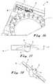
- FIG. 1is a perspective exploded view of a lancing device according to a first example embodiment of the present invention, showing a housing base and lid, a lancet carousel, a sterility cap repositioning mechanism, a lancet advancing mechanism, and a drive mechanism.
- FIG. 2is an upper perspective view of the lancing device of FIG. 1 , showing the device assembled for use with the housing lid in a second/closed position.
- FIG. 3is a lower perspective view of the lancing device of FIG. 2 .
- FIG. 4is a lower perspective view of the lancet carousel of FIG. 3 , showing a carrier and a lancet being loaded into the carrier body-first.
- FIG. 5is an upper perspective view of the lancet carousel of FIG. 1 , showing the carrier fully loaded with lancets.
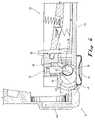
- FIG. 6is a cross-sectional side view of a portion of the lancing device of FIG. 1 , showing a first one of the lancets in a set position, the housing lid in a first/open position, and a cap-engaging member of the sterility cap repositioning mechanism in a first position.
- FIG. 7is a cross-sectional side view of the portion of the lancing device of FIG. 6 , showing the housing lid being rotated to rotate the cap-engaging member through a first motion to remove the sterility cap from the lancet tip.
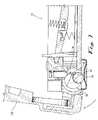
- FIG. 8is a cross-sectional side view of the portion of the lancing device of FIG. 6 , showing the housing lid in the second/closed position and the cap-engaging member in a second position with the cap clear of the housing opening.
- FIG. 9is a cross-sectional side view of the portion of the lancing device of FIG. 6 , showing the drive mechanism being actuated to launch the lancet.
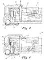
- FIG. 10is a cross-sectional side view of the portion of the lancing device of FIG. 6 , showing the housing lid and the cap-engaging member being rotated through a second motion to replace the sterility cap on the lancet and return the lancet to the set position.
- FIG. 11is a cross-sectional side view of the portion of the lancing device of FIG. 6 , showing the housing lid rotated back to the first/open position and the cap-engaging member rotated back to the first position with the cap replaced on the lancet.
- FIG. 12is a perspective view of a portion of the lancing device of FIG. 1 , showing a lancet register member of the lancet advancing mechanism when the housing lid and cap-engaging member are in the second/closed position of FIG. 8 .
- FIG. 13is a perspective view of the portion of the lancing device of FIG. 12 , showing the register member being charged as the housing lid and cap-engaging member are rotated through the second motion.
- FIG. 14is a perspective view of the portion of the lancing device of FIG. 12 , showing the register member being released as the housing lid and cap-engaging member are rotated through the second motion.
- FIG. 15is a perspective view of the portion of the lancing device of FIG. 12 , showing the register member moved to advance the lancet carrier by one lancet with the housing lid and cap-engaging member in the first/open position of FIGS. 6 and 11 .
- FIG. 16is a perspective view of the portion of the lancing device of FIG. 12 , showing the lancet register member returned to the position of FIG. 12 when the housing lid and cap-engaging member are rotated through the first motion.
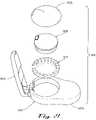
- FIG. 17is a bottom side view of the cap-engaging member of the sterility cap repositioning mechanism of FIG. 1 when in the position of FIGS. 8 and 9 .
- FIG. 18is a perspective view of the cap-engaging member of the sterility cap repositioning mechanism of FIG. 1 .
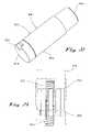
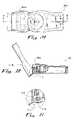
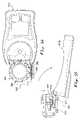
- FIG. 19is a side view of an alternative drive mechanism that can be used in the lancing device of FIG. 1 .
- FIG. 20is a perspective view of a lancing device according to a second example embodiment of the present invention, showing the device assembled for use.
- FIG. 21is a perspective exploded view of the lancing device of FIG. 20 , showing the major components of the device.
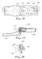
- FIG. 22is a perspective view of a lancing device according to a third example embodiment of the present invention, showing the device assembled for use.
- FIG. 23is a side view of the lancing device of FIG. 22 , showing the major internal components of the device.
- FIG. 24is an exploded view of the lancing device of FIG. 22 , showing the major components of the device.
- FIG. 25is a detail view of a cam path defined by the inside surface of the housing of the lancing device of FIG. 22 .
- FIG. 26is a plan view of a lancing device according to a fourth example embodiment of the present invention, showing a housing lid in a first/open position and a cap-engaging member of a sterility cap repositioning mechanism in a first position.
- FIG. 27is a cross-sectional side view of the lancing device taken at line 27 - 27 of FIG. 26 .
- FIG. 28is a detail view of a portion of the lancing device of FIG. 27 , showing the cap-engaging member engaging the cap.
- FIG. 29is a plan view of the lancing device of FIG. 29 , showing the cap-engaging member and the housing lid being rotated through the first motion to remove the lancet cap.
- FIG. 30is a cross-sectional side view of the lancing device taken at line 30 - 30 of FIG. 29 .
- FIG. 31is a detail view of a portion of the lancing device of FIG. 29 , showing the cap-engaging member removing the cap from the lancet.
- FIG. 32is a plan view of the lancing device of FIG. 29 , showing the cap-engaging member and the housing lid being rotated further in the first motion to remove the lancet cap.
- FIG. 33is a cross-sectional side view of the lancing device taken at line 33 - 33 of FIG. 29 .
- FIG. 34is a detail view of a portion of the lancing device of FIG. 29 , showing the cap removed off of the lancet by the cap-engaging member.
- FIG. 35is a plan view of the lancing device of FIG. 29 , showing the cap-engaging member in the de-capped position with the lancet cap removed from the lancet tip, the housing lid in the closed position, and the lancet still in the set position.
- FIG. 36is a cross-sectional side view of the lancing device taken at line 36 - 36 of FIG. 29 .
- FIG. 37is a detail view of a portion of the lancing device of FIG. 29 , showing the cap removed and retained in the housing.
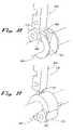
- FIG. 38is a perspective view of a portion of the cap-engaging member of FIG. 29 in the first position.
- FIG. 39is a perspective view of a portion of the cap-engaging member of FIG. 29 in the second position.
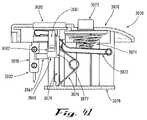
- FIG. 40is an exploded view of the drive mechanism of the lancing device of FIG. 29 , showing the major components of the drive mechanism.
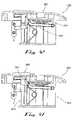
- FIG. 41is a cross-sectional view of the drive mechanism of FIG. 40 , showing the drive spring uncharged.
- FIG. 42is a cross-sectional view of the drive mechanism of FIG. 40 , showing the drive spring charged by the plunger being engaged and depressed by the housing lid.
- FIG. 43is a cross-sectional view of the drive mechanism of FIG. 40 , showing the same structure as in FIG. 42 but additionally showing the release members.
- FIG. 44is a front view of the drive mechanism of FIG. 43 , showing the release members retaining the lancet in place.
- FIG. 45is a front view of the drive mechanism of FIG. 44 , showing the release members being released so the lancet can be launched.
- FIG. 46is a cross-sectional view of the drive mechanism of FIG. 40 , showing the lancet being launched.
- FIG. 47is a cross-sectional view of the drive mechanism of FIG. 40 , showing the lancet traveling through its puncture stroke.
- FIG. 48is a cross-sectional view of the drive mechanism of FIG. 40 , showing the lancet in the puncturing position.
- FIG. 49is a cross-sectional view of the drive mechanism of FIG. 40 , showing the lancet being retracted from the puncturing position.
- FIG. 50is a side view of the lancet advancing mechanism of the lancing device of FIG. 29 , showing the housing lid in the second/closed position.
- FIG. 51is a side view of the lancet advancing mechanism of FIG. 50 , without the housing lid.
- FIG. 52is a side view of the lancet advancing mechanism of FIG. 50 , showing the register member being charged as the housing lid is rotated through the second motion.
- FIG. 53is a side view of the lancet advancing mechanism of FIG. 50 , showing the register member being released as the housing lid is rotated to the first/open position at the end of the second motion.
- FIG. 54is a plan view of the lancet advancing mechanism of FIG. 53 .
- FIG. 55is a side view of the lancet advancing mechanism of FIG. 50 , showing the housing lid in the first/open position and the register member advancing the carrier.
- FIG. 56is a plan view of the lancet advancing mechanism of FIG. 55 .
- FIG. 57is a detail perspective view of a portion of the carrier of the lancing device of FIG. 29 , showing an interior circumferential drive channel in the carrier.
- FIG. 58is a detail side view of a portion of the carrier of the lancing device of FIG. 29 , showing detents for holding the lancets in the carrier.
- Rangesmay be expressed herein as from “about” or “approximately” one particular value and/or to “about” or “approximately” another particular value. When such a range is expressed, another embodiment includes from the one particular value and/or to the other particular value. Similarly, when values are expressed as approximations, by use of the antecedent “about,” it will be understood that the particular value forms another embodiment.
- the lancing device 10includes a reusable housing 12 , a lancet carousel 14 , a sterility cap repositioning mechanism 16 , a lancet advancing mechanism 18 , and a drive mechanism 20 .
- the housing 12has a first section and a second section that is removable for loading and removing the lancet carousel 14 .
- the housing 12may include a first section base 12 a and a second section lid 12 b that is hinged to the base.
- the housing 12has a chamber 22 for the lancet carousel 14 and an opening 24 for the lancet tips to extend through to lance the user's skin.
- the housing 12may include a mounting structure for a blood testing device for use with the blood samples obtained when using the lancing device 10 .
- the housing 12may include a chamber 26 for a conventional blood meter 28 , with the lancing device 10 sold with the blood meter or separately.
- FIGS. 4 and 5show the lancet carousel 14 , which includes a carrier 30 and at least one and preferably a plurality of lancets 32 .
- the exact number of lancets 32 that the carrier 30 holdsis selected depending on space and use needs, and can vary widely.
- the lancets 32each have a sterility cap 34 protecting a lancet tip 36 (see FIGS. 6 and 7 ) that is held by a lancet body 38 .
- the lancet tip 36may be any structure for lancing skin, for example, a needle or a blade.
- the lancets 32are driven through a lancing stroke from a retracted position within the housing 12 to an extended position with the lancet tip 36 of an active lancet extending outwardly of the housing through the lancing opening 24 to pierce the skin of a human or animal subject at a lancing site.
- the carrier 30 of the lancet carousel 14may be cylindrical, or it may be polygonal or have another regular or irregular shape. Also, the carrier 30 is sized, shaped, and constructed for removable insertion into the chamber 22 of the housing 12 . In this way, after all of the lancets 32 on the carrier 30 have been used, the user can remove the spent carrier for disposal and then load a new one full of lancets.
- the carrier 30is annular-shaped and has an inner surface 40 , an outer surface 42 , and an axis 44 . Alternatively, the carrier 30 may be provided with different geometry.
- the carrier 30has a plurality of lancet openings 46 sized and shaped for receiving the lancets 32 with a free-floating fit. That is, the openings 46 are configured so that the lancets 32 can longitudinally slide freely within the openings during the lancing operation, with negligible frictional resistance to movement. In addition, the lancet openings 46 are configured in a parallel arrangement so that the lancets 32 are held by the carrier 30 in a parallel arrangement. Preferably, the lancet openings 46 and the lancets 32 are coaxially arranged relative to the axis 44 of the annular carrier 30 , as shown with particularity in FIG. 4 .
- the carrier 30has a circumferential recessed surface 48 through which the coaxial lancet openings 46 extend.
- a teardrop-shaped rim 50is formed where each of the lancet openings 46 extends through the recessed surface 48 , as shown with particularity in FIG. 4 .
- the lancet openings 46receive the lancet bodies 38 and the recessed surface 48 receives the sterility caps, while leaving the sterility caps exposed for engagement by a cap-engaging member that repositions the sterility caps, as described herein.
- the lancets 32each have a drive surface 52 for engagement with a drive member to propel the lancets, as described herein.
- the lancet drive surface 52is preferably provided by a notch in each lancet body 38 .
- the drive surface 52may be the tail end (opposite the sterility cap) of the lancet body or another surface defined on the lancet.
- the lancets 32are preferably arranged with the drive surfaces 52 extending out of the carrier 30 , as shown, so that the drive member can be moved laterally from engagement with one lancet to another one.
- the carrier 30has a plurality of lateral openings 54 that each extend between the inner surface 40 and one of the lancet openings 46 .
- the lateral openings 54are configured to receive the drive member through them in the direction of the lancing stroke so that the drive member can engage the lancet drive surface 52 through the travel of the lancet during the lancing stroke.
- the carrier 30has a plurality of register surfaces 56 (see FIG. 5 ), with each one of the register surfaces indexed to a corresponding one of the lancet openings 46 .
- the register surfaces 56are provided by ramped notches in the outer surface 42 of the carrier 30 , as shown.
- the register surfaces 56may be provided by tabs or arms extending from the carrier, recessed catch surfaces in another wall of the carrier, or otherwise. The register surfaces 56 are sequentially engaged by a register member to advance the carrier 30 , as described herein.
- the register surfaces 56advance the carrier 30 from a first position with one of the lancets 32 engaged by the drive member to a second position with a next one of the lancets engaged by the drive member.
- the lancet bodies 38are kept relatively small.
- the sterility caps 34are a little larger in order to make it easy enough to remove the sterility caps 34 to expose the lancet tip 36 for use. That is, the sterility caps 34 preferably have a larger axial profile than the lancet bodies 38 . Thus, the lancet bodies 38 slide into the lancet openings 46 , but the sterility caps 34 are too large to be received in the lancet openings.
- the lancets 32are loaded into the carrier 30 by grasping a first one of the lancets 32 and inserting it into a first one of the lancet openings 46 in a body-first orientation.
- the lancets 32are preferably inserted linearly into the openings 46 .
- the lateral openings 54may be larger and the lancets 32 inserted at an angle through the lateral openings and then tilted to their coaxial orientation.
- the lancet bodies 38may have tail-end retainer flanges that are larger than the lancet openings 46 and caps 34 that are smaller, so that the lancets 32 are loaded cap-first into the carrier 30 .
- the first lancet 32is then positioned so that its lancet body 38 is in the lancet opening 46 , its drive surface 52 is exposed for engagement by the drive member, and its sterility cap 34 is exposed for de-capping. This process is then repeated for each lancet 32 until the carrier 30 is full.
- the lancet loading processmay include restraining the lancets 32 in the openings 46 during and/or after the loading process so that they do not fall out of the carrier 30 .
- the lancets 32may be restrained by applying a cover and/or adhesive layer to the carrier 30 adjacent a tail end of the lancets to retain them in their corresponding openings 46 .
- the structure of the sterility cap repositioning mechanism 16will now be described in conjunction with an example method of operation of the sterility cap repositioning mechanism 16 to de-cap and re-cap the lancets.
- the sterility cap repositioning mechanism 16is described and shown herein with reference to the multi-lancet lancing device 10 using a lancet carousel 14 for illustration purposes only.
- the mechanism 16can be used in other multi-lancet devices, or even adapted for use with single-use disposable lancets (without an advancing mechanism), if so desired.
- the sterility cap repositioning mechanism 16includes a cap-engaging member 58 that is movably coupled to the housing 12 .
- the cap-engaging member 58may be rotationally coupled to the housing 12 by an axle 60 .
- the cap-engaging member 58is operated by an actuating member.
- the axle 60may be keyed to the housing lid 12 b so that they move together, whereby the housing lid serves as the actuating member in addition to covering the lancet-holding chamber 22 .
- the housing lid 12 bmay be provided with a gripping surface or member, if desired, to make it easy to grasp for opening and closing.
- the cap-engaging member 58has a cap opening 62 , a body opening 64 , and a channel 66 between the cap opening and the body opening.
- the cap opening 62is configured to eccentrically receive and engage the sterility caps 34 when the cap-engaging member 58 is rotated from a first position through a first motion.
- the channel 66is configured to receive the lancet tips 36 through it when the cap-engaging member 58 is rotated through the first motion.
- the body opening 64is configured to receive the lancet bodies 38 through it free-floatingly when, with the cap-engaging member 58 rotated to a second position at the end of the first motion, the lancing device 10 is actuated.
- the cap opening 62 , the body opening 64 , and the channel 66are curved, for example, they have semi-circular profiles formed in a spherical body for use with lancets 32 having cylindrical bodies and spherical caps, as is shown.
- the cap opening 62 and the body opening 64may have profiles that are rectangular or have another regular or irregular shape.
- the cap opening 62 and the body opening 64may intersect with each other making the channel 66 effectively a part of the body opening, or the channel 66 may be sized and shaped similarly to the body opening 64 , but these configurations leave less surface area in the cap opening for engaging and removing the caps 34 .
- FIG. 6shows the lancing device 10 with a first one of the lancets 32 in a set position, with the sterility cap 34 between the lancet tip 36 and the housing opening 24 , and engaged by the drive member 68 .
- the housing lid 12 bis in the first/open position and the cap-engaging member 58 is in the first/capped position adjacent the sterility cap.
- the lancet carousel 14may be provided with a dummy lancet (without a lancet tip or sterility cap) for initial engagement by the cap-engaging member 58 , which would eliminate any clearance problems with inserting the carousel into the housing with one of the caps engaged with the cap-engaging member 58 .
- the useroperates the actuating member (the housing lid 12 b in this embodiment).
- FIG. 7shows the housing lid 12 b being rotated to rotate the cap-engaging member 58 through the first motion.
- the cap opening 62receives the sterility cap 34 and pulls it off of the lancet tip 36 as the cap-engaging member 58 rotates.
- the channel 66receives the lancet tip 36 during this motion to eliminate interference and permit the cap-engaging member 58 to rotate past the lancet tip.
- FIG. 8shows the housing lid 12 b rotated to the second/closed position and the cap-engaging member 58 rotated to the second position.
- the cap-engaging member 58has rotated the sterility cap 34 off of the lancet tip 36 to a position clear of the housing opening 24 .
- the cap-engaging member 58 in the second positionretains the sterility cap 34 within the housing, as shown, so the cap can be replaced on the lancet tip 36 after the skin is lanced.
- the lancing device 10is now ready to be actuated, by operation of the drive mechanism 20 , to lance the user's skin.
- the drive mechanism 20includes a frame 70 for a spring arm 72 that is biased by a drive spring 74 and a return spring 76 , with the spring arm pivotally engaging the drive member 68 (see also FIG. 1 ).
- a drive spring 74 and a return spring 76When the housing lid 12 b is moved to the second/closed position, it compresses and charges the drive spring 74 against the spring arm 72 , thereby charging the drive member 68 .
- the spring arm 72pivots relative to the drive member 68 by a tongue and recess structure as shown, by a pivot pin and slot, or otherwise.
- the springs 74 and 76may be held in place by recesses as shown or otherwise, and other types, lengths, and configurations of springs may be provided.
- the drive mechanism 20further includes a releasable catch member 78 that releasably engages the drive member 68 , and a drive actuating member 80 that the user presses or otherwise moves to release the catch member 78 from the drive member 68 .
- the catch member 78may releasably engage the drive member 68 by, for example, the ramp-and-notch structures 82 shown.
- FIG. 9shows the drive mechanism 20 being actuated to launch the lancet 32 .
- the userpresses the drive actuating member 80 (in the direction of the adjacent arrow), which pushes back the releasable catch member 78 (in the direction of the adjacent arrow) from engagement with the drive member 68 .
- a drive surface 67preferably on a drive arm or other protrusion, of the drive member 68 engages the drive surface 52 of the lancet 32 , so that movement of the drive member produces movement of the lancet.
- the drive member 68charged by the drive spring 74 , launches the lancet 32 (in the direction of the adjacent arrow).
- the lancet body 38passes through the body opening 64 of the cap-engaging member 58 , which when viewed from the bottom now appears as shown in FIG. 17 .
- the lancet tip 36extends through the housing opening 24 to lance the user's skin.
- the return spring 76is now compressed and charged, ready to retract the drive member 68 and thus the lancet 32 back safely into the housing so that the next lancet 32 ′ can be advanced into engagement with the drive member 68 for use.
- FIG. 10shows the housing lid 12 b being rotated to rotate the cap-engaging member 58 from the second position, through the second motion, and back to the first position.
- the cap-engaging member 58rotates to place the sterility cap 34 on the lancet tip 36 .
- the cap repositioning mechanism 16is configured to replace the sterility cap 34 on the lancet tip 36 that it was previously removed from.
- the drive spring 74is not charged by this motion because the housing lid is being rotated away out of engagement with the drive spring.
- FIG. 11shows the housing lid 12 b rotated back to the first/open position and the cap-engaging member 58 rotated back to the first position with the cap 34 replaced on the lancet 32 .
- the spent lancet 32is advanced and the next lancet on the carrier 30 is advanced into the set position of FIG. 6 , and the process is repeated until the lancet carousel 14 is spent.
- the usercan open the housing lid 12 b , remove the spent lancet carousel 14 , install a new lancet carousel, and close the lid for further use.
- the structure of the lancet advancing mechanism 18will now be described in conjunction with an example method of operation of the lancet advancing mechanism 18 to advance lancets in a lancet carrier.
- the lancet advancing mechanism 18is described and shown herein with reference to the multi-lancet lancing device 10 using a lancet carousel 14 for illustration purposes only.
- the mechanism 18can be readily adapted for use with other multi-lancet lancing devices and lancet carousels, including disposable lancing devices if so desired.
- FIG. 12shows the position of the lancet register member 84 when the housing lid and cap-engaging member are in the second/closed position of FIG. 8 .
- the lancet register member 84is preferably operably coupled to the cap-engaging member 58 so that the sterility cap repositioning mechanism 16 and the lancet advancing mechanism 18 are operated together by the same actuating member, which is the housing lid in this embodiment.
- the lancet advancing mechanism 18may be coupled to the axle 60 of the cap-engaging member 58 .
- a direction-reversing linkage(not shown) is provided so that when the cap-engaging member 58 rotates on one direction an advancing arm 86 of the lancet advancing mechanism 18 rotates in the opposite direction.
- the lancet advancing mechanism 18may be readily adapted to eliminate the direction-reversing linkage, as would be understood by a person of ordinary skill in the art.
- the lancet register member 84engages and advances the carrier 30 to sequentially move the lancets 32 into the set position for use.
- the lancet register member 84is configured to advance a first lancet out of engagement with the drive member and to advance a second lancet into engagement with the drive member during the second motion after the first lancet has been re-capped and reset.
- the register member 84includes a ramp 88 that releasably engages the preferred ramp-notched register surfaces 56 of the carrier 30 .
- FIG. 13shows the register member 84 being charged as the housing lid and cap-engaging member are rotated through the second motion (see FIG. 10 ).
- the lancet advancing mechanism 18further includes an advancing slide member 90 that is coupled to the advancing arm 86 so that rotation of the advancing arm produces lateral movement of the slide member.
- the slide member 90 and the advancing arm 86may be coupled together by a pin-and-groove structure 92 as shown.
- an advancing spring 94see FIG. 12
- the register member 84is retained in position to charge the spring 94 by a ramped engagement member 96 that in turn is retained in position by a catch member 98 .
- FIGS. 14 and 15show the register member 84 being released as the housing lid and cap-engaging member are rotated through the end of the second motion (see FIGS. 6 and 11 ).
- the slide member 90includes an advancing release member 100 that engages and releases the ramped engagement member 96 so that it can move past the catch member 98 .
- the release member 100advances, it slides along the ramped engagement member 96 , as shown in FIG. 14 .
- Thiscauses the ramped engagement member 96 to deflect, which releases the register member 84 to shoot past the catch member 98 by the charged spring 94 to the position shown in FIG. 15 .
- This movement by the register member 84rotates the carrier 30 (in the direction of arrow 102 ) by one lancet position, so that the next lancet is now in the set position, engaged by the drive member and ready for use.
- FIG. 16shows the lancet register member 84 returned to the start position of FIG. 12 .
- FIG. 19there is shown an alternative drive mechanism 20 a that can be used interchangeably in the lancing device 10 .
- the drive mechanism 20 ais operable with the same carrier 30 a holding lancets 32 a .
- the drive spring 74 a and the return spring 76 aare coaxially arranged.
- the drive member 68 a and the spring arm 72 aare provided as a unitary piece that move together in the lancet stroke direction.
- this lancing device 1010has a housing 1012 with a base 1012 a and a lid 1012 b , a lancet carousel 1014 , and a drive mechanism 1020 .
- the lancing device 1010has an actuating member 1012 c that is separate and distinct from the housing lid 1012 b . In this way, the lancet carousel 1014 is not exposed (by opening the lid 1012 b ) every time the user advances a fresh lancet for use.
- this lancing device 2010has a housing 1212 with a base 2012 a , a removable lid 1012 b , and an actuating member 2012 c .
- the housing 2012has an opening 2024 for sequentially receiving the lancets 2032 loaded onto the carrier 2030 of a lancet carousel 2014 .
- the drive mechanismincludes a drive spring 2074 and a return spring 2076 that are charged to move a drive member 2068 .
- the drive member 2068has a plurality of parallel lancet openings 2069 and the lancet openings 2046 of the carrier 2030 are alignable with the drive member lancet openings. In this way, the carrier 2030 can be inserted into the housing 2012 with the lancets 2032 received through the aligned sets of openings 2046 and 2069 .
- the lancing device 2010includes a lancet advancing mechanism having a cam path 2085 that cooperatively engages one or more followers 2087 .
- the cam path 2030may be defined by an interior wall of the housing 2012 and the followers 2087 may extend from the drive member 2068 , or vice versa.
- the lancet advancing mechanismfurther includes a ramped cam member 2093 that is cooperatively engaged by one or more register members 2091 .
- the ramped cam member 2093may extend from the drive member 2068 and the register members 2091 may extend from the actuating member 2012 c , or vice versa.
- the register members 2091contact and slide along the ramped cam member 2093 , which causes the drive member 2068 and lancet carousel 2014 to turn in the direction of arrow 2095 .
- the cam surface 2085then leads the follower 2087 and the drive member 2068 to move from the rest position 2085 a to the charged position 2085 b , which charges the drive spring 2074 .
- the follower 2087is turned just past the charged position 2085 b , it is free to move within the cam surface 2085 in the direction of the lancing stroke.
- the drive member 2068 and lancet carousel 2014are thereby released to be launched by the charged drive spring 2074 to the fully extended lancing position 2087 c .
- the return spring 2076then retracts the drive member 2068 and lancet carousel 2014 back to the rest position 12 a , and then the process is repeated until the lancet carousel is spent.
- the cam surface 2085 in this configurationthe lancets 2032 are sequentially charged, launched, and advanced all by once depressing the actuator member 2012 c.
- this lancing device 3010has a housing 3012 with a base 3012 a and a lid 3012 b , a lancet carousel 3014 , a sterility cap repositioning mechanism 3016 , a lancet advancing mechanism 3018 , and a drive mechanism 3020 .
- this embodimentthere are modifications in the sterility cap repositioning mechanism 3016 , the lancet advancing mechanism 3018 , and the drive mechanism 3020 .
- FIGS. 26-39show the structure and operation of the sterility cap repositioning mechanism 3016 .
- FIGS. 26-28show the sterility cap repositioning mechanism 3016 in a position corresponding to FIG. 6 , with the cap-engaging member 3058 in the capped position with its cap opening 3062 receiving the lancet cap 3034 , the housing lid 3012 b in the open position, and the lancet 3032 in the set position.
- FIGS. 29-31show the sterility cap repositioning mechanism 3016 with the cap-engaging member 3058 and the housing lid 3012 b being rotated through the first motion to remove the lancet cap 3034 .
- FIGS. 35-38show the sterility cap repositioning mechanism 3016 in a position corresponding to FIG. 8 , with the cap-engaging member 3058 in the de-capped position with the lancet cap 3034 removed from the lancet tip 3036 , the housing lid 3012 b in the closed position, and the lancet 3032 still in the set position.
- FIGS. 38 and 39correspond to FIGS. 28 and 37 , respectively, and show details of the cap-engaging member 3058 including its cap opening 3062 , its body opening 3064 , and its channel 3066 .
- the lancet body 3038has a generally rectangular profile and so too does the body opening 3064 .
- the cap 3034is generally cylindrical but has a generally circular profile, so the cap opening 3064 has a semi-circular profile too.
- FIGS. 40-49show the operation of the drive mechanism 3020 .
- FIGS. 40 and 41show the major components of the drive mechanism 3020 , which include the drive member 3068 , the frame 3070 , the spring arm 3072 , the drive spring 3074 , the return spring 3076 , the releasable catch members 3078 (see FIGS. 43-45 ), and the drive actuating member 3080 .
- the spring arm 3072is biased by the drive spring 3074 and the return spring 3076 .
- the drive spring 3074is preferably a compression spring and the return spring 3076 is preferably a torsion spring, as shown.
- a plunger 3075engages the drive spring and extends from the frame 3070 for operable engagement by the housing lid.
- the releasable catch members 3078releasably engage the drive member 3068 in the set position by, for example, the catches 3082 shown on the drive member.
- the drive actuating member 3080has actuating arms 3081 that contact and spread the releasable catch members 3078 to release them from the catches 3082 on the drive member 3068 .
- the drive member 3068has guide arms 3077 that ride in guide slots 3079 in the frame 3070 . And the drive arm 3052 of the lancet 3032 engages the drive notch 3067 of the drive member 3068 .
- FIG. 42when the user moves the housing lid 3012 b to the second/closed position, it engages the plunger 3075 to compress and charge the drive spring 3074 against the spring arm 3072 , thereby charging the drive member 3068 .
- FIGS. 43 and 44show the drive mechanism 3020 in the same position as in FIG. 42 , but additionally show the release members 3078 .
- FIG. 45shows the drive mechanism 3020 being actuated to launch the lancet 3032 . To do this, the user depresses the drive actuating member 3080 , which pushes the actuating arms 3081 into contact with and spreads apart the release members 3078 from engagement with the catches 3082 .
- the drive member 3068charged by the drive spring 3074 via the spring arm 3072 , launches the lancet 3032 through a puncturing stroke, as shown in FIGS. 46 and 47 , to the puncturing position shown in FIG. 48 .
- the lancet body 3038passes through the body opening 3064 of the cap-engaging member 3058 (see FIG. 39 ).
- the return spring 3076retracts the lancet 3032 into the housing 3012 until the drive spring 3074 and the return spring reach a neutral, balanced position.
- the lancets 3032 in this positioncannot be advanced. This is because the drive notch 3052 of the lancet 3032 is not aligned with an interior circumferential drive channel (described below) in the carrier. Only after the housing lid 12 b is opened, which relieves all charge on the drive spring 3074 , does the return spring 3076 return the lancet 3032 , the drive member 3068 , and the spring arm 3072 to the set position.
- the drive mechanism 3020is now ready for recharging when the housing lid 3012 b is closed again to engage the plunger 3075 again.
- FIGS. 50-56show the structure and operation of the lancet advancing mechanism 3018 .
- FIGS. 50 and 51show the position of the lancet register member 3084 when the housing lid is in the second/closed position.
- the lancet register member 3084is operably coupled to the cap-engaging member so that the sterility cap repositioning mechanism 3016 and the lancet advancing mechanism 3018 are operated together by the same actuating member, which is the housing lid 3012 b in this embodiment.
- the lancet advancing mechanism 3018may be coupled to the axle 3060 of the cap-engaging member 3058 .
- the lancet register member 3084engages and advances the carrier 3030 to sequentially move the lancets into the set position for use.
- the lancet register member 3084is configured to advance a first lancet out of engagement with the drive member and to advance a second lancet into engagement with the drive member during the second motion after the first lancet has been re-capped and reset.
- the register member 3084includes a ramp 3088 that releasably engages the preferred ramp-notched register surfaces 3056 of the carrier 3030 (see FIG. 54 ).
- the lancet advancing mechanism 3018further includes an advancing actuator member 3090 that is eccentrically coupled to axle 3060 by an advancing arm 3086 so that rotation of the advancing arm pulls on the actuator member.
- the register member 3084has an engagement surface 3096 that catches on a catch member 3098 on the housing, thereby retaining the register member in position.
- an advancing spring 3094is tensioned and charged.
- the advancing spring 3094may be a band of elastic material, a helical spring, or another spring element.
- FIGS. 53 and 54show the register member 3084 being released as the housing lid is rotated to the first/open position at the end of the second motion.
- the actuator member 3090includes a looped section 3091 with an inner radius that generally matches the outer radius of the axel 3060 , and with a center that is aligned with the axis of the remainder of the advancing arm and inset from the end of the actuator arm by the length of the advancing arm 3086 . In this way, just before the lid 3012 b reaches the first/open position shown, the looped section 3091 seats onto the axle 3060 , so that further rotation of the axle and advancing arm causes the actuator member 3090 to rotate with the axle.
- the advancing arm 3086is rotated to push the actuator member 3090 and the register member 3084 back to the start position. The process is repeated after the next lancet is used and the advancing mechanism 3018 is operated.
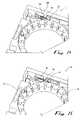
- FIGS. 57 and 58show additional details of the carrier 3030 .
- FIG. 57there is shown the interior circumferential drive channel in the inner surface 3040 of the carrier 3030 .
- the drive mechanism 3020when one of the lancets 3032 is retracted back into the housing 3012 and it lancet opening 3046 after firing, it returns to a neutral, balanced position. Then after the housing lid 3012 b is opened, which relieves all charge on the drive spring, the return spring returns the lancet 3032 , the drive member, and the spring arm to the set position, with the drive member moving up through the lateral opening 3054 .
- the drive notch of the lancetis now aligned with the interior circumferential drive channel 3055 in the carrier 3030 . So the carrier 3030 can now be rotationally advanced, because the drive member can now pass laterally out of the drive notch of the just-used lancet, through the interior circumferential drive channel 3055 , and into the drive notch of a next lancet.
- FIG. 58there are shown retainers or detents that releasably hold the sterility caps 3034 to the carrier 3030 .
- the retainers or detentscan be provided by male protrusions 3031 from inner walls of recesses on the carrier 3030 that engage female wells 3035 in the caps 3034 , or vice versa.
- the retainers or detentsprovide enough holding force so that the lancets 3032 are held in the carrier 3030 with an interference or press fit.
- the caps 3034are removed from the lancet 3032 , the lancets are free to move within the lancet openings for puncturing. Then after re-capping the lancets 3032 , the caps 3034 now hold the lancets in place again.
- the present inventionprovides a number of advantages over the known lancing devices.
- a lancet carouselthat advantageously permits de-capping, charging, actuating, and re-capping of a lancet in the carousel, and then advancing a next lancet in the carousel for use.
- a lancing devicewith an innovative sterility cap repositioning mechanism and lancet advancing mechanism that increase the convenience of use to facilitate taking multiple blood samples without the risk of infection or contamination.
Landscapes
- Health & Medical Sciences (AREA)
- Life Sciences & Earth Sciences (AREA)
- Physics & Mathematics (AREA)
- Heart & Thoracic Surgery (AREA)
- Molecular Biology (AREA)
- Pathology (AREA)
- Engineering & Computer Science (AREA)
- Biomedical Technology (AREA)
- Hematology (AREA)
- Medical Informatics (AREA)
- Biophysics (AREA)
- Surgery (AREA)
- Animal Behavior & Ethology (AREA)
- General Health & Medical Sciences (AREA)
- Public Health (AREA)
- Veterinary Medicine (AREA)
- Geometry (AREA)
- Dermatology (AREA)
- Measurement Of The Respiration, Hearing Ability, Form, And Blood Characteristics Of Living Organisms (AREA)
Abstract
Description
Claims (21)
Priority Applications (1)
| Application Number | Priority Date | Filing Date | Title |
|---|---|---|---|
| US10/921,487US7678127B2 (en) | 2003-08-20 | 2004-08-19 | Multi-lancet device with sterility cap repositioning mechanism |
Applications Claiming Priority (3)
| Application Number | Priority Date | Filing Date | Title |
|---|---|---|---|
| US49702403P | 2003-08-20 | 2003-08-20 | |
| US59814704P | 2004-08-02 | 2004-08-02 | |
| US10/921,487US7678127B2 (en) | 2003-08-20 | 2004-08-19 | Multi-lancet device with sterility cap repositioning mechanism |
Publications (2)
| Publication Number | Publication Date |
|---|---|
| US20050149089A1 US20050149089A1 (en) | 2005-07-07 |
| US7678127B2true US7678127B2 (en) | 2010-03-16 |
Family
ID=34221436
Family Applications (1)
| Application Number | Title | Priority Date | Filing Date |
|---|---|---|---|
| US10/921,487Active2028-08-30US7678127B2 (en) | 2003-08-20 | 2004-08-19 | Multi-lancet device with sterility cap repositioning mechanism |
Country Status (4)
| Country | Link |
|---|---|
| US (1) | US7678127B2 (en) |
| EP (1) | EP1663001A2 (en) |
| JP (1) | JP2007502666A (en) |
| WO (1) | WO2005018454A2 (en) |
Cited By (10)
| Publication number | Priority date | Publication date | Assignee | Title |
|---|---|---|---|---|
| US20080058849A1 (en)* | 2004-04-16 | 2008-03-06 | Conway William E | Cap displacement mechanism for lancing device and multi-lancet cartridge |
| US20090099585A1 (en)* | 2003-11-12 | 2009-04-16 | Conway William E | Lancing device with multi-lancet cartridge |
| USD628293S1 (en) | 2008-12-18 | 2010-11-30 | Facet Technologies, Llc | Lancing device |
| USD634426S1 (en) | 2010-04-08 | 2011-03-15 | Facet Technologies, Llc | Lancing device |
| US8398664B2 (en) | 2008-12-18 | 2013-03-19 | Facet Technologies, Llc | Lancing device and lancet |
| US20140088633A1 (en)* | 2012-09-27 | 2014-03-27 | Facet Technologies, Llc | Depth-adjust mechanism for lancing device |
| US8758381B2 (en)* | 2010-12-04 | 2014-06-24 | Roche Diagnostics Operations, Inc. | Lancet device with optionally reusable lancets stored in a magazine |
| US9844331B2 (en) | 2011-12-15 | 2017-12-19 | Facet Technologies, Llc | Latch mechanism for preventing lancet oscillation in a lancing device |
| US10085681B2 (en) | 2012-04-11 | 2018-10-02 | Facet Technologies, Llc | Lancing device with moving pivot depth adjust |
| US10456069B2 (en) | 2012-04-12 | 2019-10-29 | Facet Technologies, Llc | Lancing device with side activated charge and eject mechanisms |
Families Citing this family (83)
| Publication number | Priority date | Publication date | Assignee | Title |
|---|---|---|---|---|
| US6036924A (en) | 1997-12-04 | 2000-03-14 | Hewlett-Packard Company | Cassette of lancet cartridges for sampling blood |
| US6391005B1 (en) | 1998-03-30 | 2002-05-21 | Agilent Technologies, Inc. | Apparatus and method for penetration with shaft having a sensor for sensing penetration depth |
| US8641644B2 (en) | 2000-11-21 | 2014-02-04 | Sanofi-Aventis Deutschland Gmbh | Blood testing apparatus having a rotatable cartridge with multiple lancing elements and testing means |
| DE10057832C1 (en) | 2000-11-21 | 2002-02-21 | Hartmann Paul Ag | Blood analysis device has syringe mounted in casing, annular mounting carrying needles mounted behind test strip and being swiveled so that needle can be pushed through strip and aperture in casing to take blood sample |
| JP4272051B2 (en) | 2001-06-12 | 2009-06-03 | ペリカン テクノロジーズ インコーポレイテッド | Blood sampling apparatus and method |
| US7981056B2 (en) | 2002-04-19 | 2011-07-19 | Pelikan Technologies, Inc. | Methods and apparatus for lancet actuation |
| US9427532B2 (en) | 2001-06-12 | 2016-08-30 | Sanofi-Aventis Deutschland Gmbh | Tissue penetration device |
| WO2002101359A2 (en) | 2001-06-12 | 2002-12-19 | Pelikan Technologies, Inc. | Integrated blood sampling analysis system with multi-use sampling module |
| US9226699B2 (en) | 2002-04-19 | 2016-01-05 | Sanofi-Aventis Deutschland Gmbh | Body fluid sampling module with a continuous compression tissue interface surface |
| US9795747B2 (en) | 2010-06-02 | 2017-10-24 | Sanofi-Aventis Deutschland Gmbh | Methods and apparatus for lancet actuation |
| US7344507B2 (en) | 2002-04-19 | 2008-03-18 | Pelikan Technologies, Inc. | Method and apparatus for lancet actuation |
| US8337419B2 (en) | 2002-04-19 | 2012-12-25 | Sanofi-Aventis Deutschland Gmbh | Tissue penetration device |
| US7041068B2 (en) | 2001-06-12 | 2006-05-09 | Pelikan Technologies, Inc. | Sampling module device and method |
| EP1395185B1 (en) | 2001-06-12 | 2010-10-27 | Pelikan Technologies Inc. | Electric lancet actuator |
| JP4209767B2 (en) | 2001-06-12 | 2009-01-14 | ペリカン テクノロジーズ インコーポレイテッド | Self-optimized cutting instrument with adaptive means for temporary changes in skin properties |
| AU2002344825A1 (en) | 2001-06-12 | 2002-12-23 | Pelikan Technologies, Inc. | Method and apparatus for improving success rate of blood yield from a fingerstick |
| US7749174B2 (en) | 2001-06-12 | 2010-07-06 | Pelikan Technologies, Inc. | Method and apparatus for lancet launching device intergrated onto a blood-sampling cartridge |
| US7344894B2 (en) | 2001-10-16 | 2008-03-18 | Agilent Technologies, Inc. | Thermal regulation of fluidic samples within a diagnostic cartridge |
| US7291117B2 (en) | 2002-04-19 | 2007-11-06 | Pelikan Technologies, Inc. | Method and apparatus for penetrating tissue |
| US8784335B2 (en) | 2002-04-19 | 2014-07-22 | Sanofi-Aventis Deutschland Gmbh | Body fluid sampling device with a capacitive sensor |
| US7491178B2 (en) | 2002-04-19 | 2009-02-17 | Pelikan Technologies, Inc. | Method and apparatus for penetrating tissue |
| US7547287B2 (en) | 2002-04-19 | 2009-06-16 | Pelikan Technologies, Inc. | Method and apparatus for penetrating tissue |
| US8267870B2 (en) | 2002-04-19 | 2012-09-18 | Sanofi-Aventis Deutschland Gmbh | Method and apparatus for body fluid sampling with hybrid actuation |
| US7582099B2 (en) | 2002-04-19 | 2009-09-01 | Pelikan Technologies, Inc | Method and apparatus for penetrating tissue |
| US9795334B2 (en) | 2002-04-19 | 2017-10-24 | Sanofi-Aventis Deutschland Gmbh | Method and apparatus for penetrating tissue |
| US7229458B2 (en) | 2002-04-19 | 2007-06-12 | Pelikan Technologies, Inc. | Method and apparatus for penetrating tissue |
| US7892183B2 (en) | 2002-04-19 | 2011-02-22 | Pelikan Technologies, Inc. | Method and apparatus for body fluid sampling and analyte sensing |
| US7524293B2 (en) | 2002-04-19 | 2009-04-28 | Pelikan Technologies, Inc. | Method and apparatus for penetrating tissue |
| US8221334B2 (en) | 2002-04-19 | 2012-07-17 | Sanofi-Aventis Deutschland Gmbh | Method and apparatus for penetrating tissue |
| US7563232B2 (en) | 2002-04-19 | 2009-07-21 | Pelikan Technologies, Inc. | Method and apparatus for penetrating tissue |
| US7717863B2 (en) | 2002-04-19 | 2010-05-18 | Pelikan Technologies, Inc. | Method and apparatus for penetrating tissue |
| US9314194B2 (en) | 2002-04-19 | 2016-04-19 | Sanofi-Aventis Deutschland Gmbh | Tissue penetration device |
| US8579831B2 (en) | 2002-04-19 | 2013-11-12 | Sanofi-Aventis Deutschland Gmbh | Method and apparatus for penetrating tissue |
| US7232451B2 (en) | 2002-04-19 | 2007-06-19 | Pelikan Technologies, Inc. | Method and apparatus for penetrating tissue |
| US7141058B2 (en) | 2002-04-19 | 2006-11-28 | Pelikan Technologies, Inc. | Method and apparatus for a body fluid sampling device using illumination |
| US7331931B2 (en) | 2002-04-19 | 2008-02-19 | Pelikan Technologies, Inc. | Method and apparatus for penetrating tissue |
| US9248267B2 (en) | 2002-04-19 | 2016-02-02 | Sanofi-Aventis Deustchland Gmbh | Tissue penetration device |
| US7297122B2 (en) | 2002-04-19 | 2007-11-20 | Pelikan Technologies, Inc. | Method and apparatus for penetrating tissue |
| US7648468B2 (en) | 2002-04-19 | 2010-01-19 | Pelikon Technologies, Inc. | Method and apparatus for penetrating tissue |
| US7410468B2 (en) | 2002-04-19 | 2008-08-12 | Pelikan Technologies, Inc. | Method and apparatus for penetrating tissue |
| US7481776B2 (en) | 2002-04-19 | 2009-01-27 | Pelikan Technologies, Inc. | Method and apparatus for penetrating tissue |
| US7976476B2 (en) | 2002-04-19 | 2011-07-12 | Pelikan Technologies, Inc. | Device and method for variable speed lancet |
| US7708701B2 (en) | 2002-04-19 | 2010-05-04 | Pelikan Technologies, Inc. | Method and apparatus for a multi-use body fluid sampling device |
| US7909778B2 (en) | 2002-04-19 | 2011-03-22 | Pelikan Technologies, Inc. | Method and apparatus for penetrating tissue |
| US7374544B2 (en) | 2002-04-19 | 2008-05-20 | Pelikan Technologies, Inc. | Method and apparatus for penetrating tissue |
| US8702624B2 (en) | 2006-09-29 | 2014-04-22 | Sanofi-Aventis Deutschland Gmbh | Analyte measurement device with a single shot actuator |
| US7371247B2 (en) | 2002-04-19 | 2008-05-13 | Pelikan Technologies, Inc | Method and apparatus for penetrating tissue |
| US7901362B2 (en) | 2002-04-19 | 2011-03-08 | Pelikan Technologies, Inc. | Method and apparatus for penetrating tissue |
| US7674232B2 (en) | 2002-04-19 | 2010-03-09 | Pelikan Technologies, Inc. | Method and apparatus for penetrating tissue |
| US8574895B2 (en) | 2002-12-30 | 2013-11-05 | Sanofi-Aventis Deutschland Gmbh | Method and apparatus using optical techniques to measure analyte levels |
| US7850621B2 (en) | 2003-06-06 | 2010-12-14 | Pelikan Technologies, Inc. | Method and apparatus for body fluid sampling and analyte sensing |
| WO2006001797A1 (en) | 2004-06-14 | 2006-01-05 | Pelikan Technologies, Inc. | Low pain penetrating |
| EP1635700B1 (en) | 2003-06-13 | 2016-03-09 | Sanofi-Aventis Deutschland GmbH | Apparatus for a point of care device |
| US20190357827A1 (en) | 2003-08-01 | 2019-11-28 | Dexcom, Inc. | Analyte sensor |
| US8282576B2 (en) | 2003-09-29 | 2012-10-09 | Sanofi-Aventis Deutschland Gmbh | Method and apparatus for an improved sample capture device |
| EP1680014A4 (en) | 2003-10-14 | 2009-01-21 | Pelikan Technologies Inc | METHOD AND DEVICE FOR A VARIABLE USER INTERFACE |
| US7822454B1 (en) | 2005-01-03 | 2010-10-26 | Pelikan Technologies, Inc. | Fluid sampling device with improved analyte detecting member configuration |
| US8668656B2 (en) | 2003-12-31 | 2014-03-11 | Sanofi-Aventis Deutschland Gmbh | Method and apparatus for improving fluidic flow and sample capture |
| WO2009048462A1 (en) | 2007-10-09 | 2009-04-16 | Dexcom, Inc. | Integrated insulin delivery system with continuous glucose sensor |
| WO2006011062A2 (en) | 2004-05-20 | 2006-02-02 | Albatros Technologies Gmbh & Co. Kg | Printable hydrogel for biosensors |
| WO2005120365A1 (en) | 2004-06-03 | 2005-12-22 | Pelikan Technologies, Inc. | Method and apparatus for a fluid sampling device |
| DE102004042886A1 (en)* | 2004-09-04 | 2006-03-30 | Roche Diagnostics Gmbh | Lancet device for creating a puncture wound |
| US8211038B2 (en) | 2004-09-17 | 2012-07-03 | Abbott Diabetes Care Inc. | Multiple-biosensor article |
| US8652831B2 (en) | 2004-12-30 | 2014-02-18 | Sanofi-Aventis Deutschland Gmbh | Method and apparatus for analyte measurement test time |
| US20060247670A1 (en)* | 2005-05-02 | 2006-11-02 | Levaughn Richard W | Lancing device with automatic lancet release |
| FI121698B (en)* | 2005-07-19 | 2011-03-15 | Ihq Innovation Headquarters Oy | Health monitoring device and sensor cassette for the health monitoring device |
| EP1996914B1 (en)* | 2006-03-10 | 2016-04-27 | Sanofi-Aventis Deutschland GmbH | Method for loading penetrating members in a collection device during manufacture |
| WO2008064333A2 (en)* | 2006-11-21 | 2008-05-29 | Stat Medical Devices, Inc. | Lancet device utilizing a revolver-type cartridge, revolver-type cartridge, and method of making and/or using the cartridge and the lancet device |
| GB2451839A (en) | 2007-08-14 | 2009-02-18 | Owen Mumford Ltd | Lancing device |
| EP2265324B1 (en) | 2008-04-11 | 2015-01-28 | Sanofi-Aventis Deutschland GmbH | Integrated analyte measurement system |
| US8029526B2 (en)* | 2008-08-14 | 2011-10-04 | Abbott Diabetes Care Inc. | Cocking mechanism for lancing device |
| US9375169B2 (en) | 2009-01-30 | 2016-06-28 | Sanofi-Aventis Deutschland Gmbh | Cam drive for managing disposable penetrating member actions with a single motor and motor and control system |
| PL2218399T3 (en) | 2009-02-17 | 2014-03-31 | Hoffmann La Roche | Reuse protection for lancet system |
| US8965476B2 (en) | 2010-04-16 | 2015-02-24 | Sanofi-Aventis Deutschland Gmbh | Tissue penetration device |
| EP2697650B1 (en) | 2011-04-15 | 2020-09-30 | Dexcom, Inc. | Advanced analyte sensor calibration and error detection |
| EP2522378A1 (en)* | 2011-05-11 | 2012-11-14 | Sanofi-Aventis Deutschland GmbH | Needle assembly storage device |
| EP2617356A1 (en)* | 2012-01-18 | 2013-07-24 | Roche Diagniostics GmbH | Analytic system for testing a bodily fluid and method for its operation |
| EP4026488B1 (en) | 2015-12-30 | 2023-07-19 | Dexcom, Inc. | Transcutaneous analyte sensor systems and methods |
| EP4111949B1 (en) | 2017-06-23 | 2023-07-26 | Dexcom, Inc. | Transcutaneous analyte sensors, applicators therefor, and needle hub comprising anti-rotation feature |
| US11331022B2 (en) | 2017-10-24 | 2022-05-17 | Dexcom, Inc. | Pre-connected analyte sensors |
| US20190120785A1 (en) | 2017-10-24 | 2019-04-25 | Dexcom, Inc. | Pre-connected analyte sensors |
| USD926325S1 (en) | 2018-06-22 | 2021-07-27 | Dexcom, Inc. | Wearable medical monitoring device |
| CN116725534B (en)* | 2023-08-11 | 2024-03-19 | 海口海关技术中心 | Experimental monkey pathogen detection equipment convenient to rapid detection |
Citations (68)
| Publication number | Priority date | Publication date | Assignee | Title |
|---|---|---|---|---|
| US4627445A (en) | 1985-04-08 | 1986-12-09 | Garid, Inc. | Glucose medical monitoring system |
| US4787398A (en) | 1985-04-08 | 1988-11-29 | Garid, Inc. | Glucose medical monitoring system |
| US4794926A (en) | 1986-11-24 | 1989-01-03 | Invictus, Inc. | Lancet cartridge |
| US4823806A (en) | 1985-11-18 | 1989-04-25 | Serge Bajada | Apparatus for testing the sensory system on humans or animals |
| US4974926A (en) | 1989-04-06 | 1990-12-04 | At&T Bell Laboratories | Underwater optical fiber cable |
| EP0449525A1 (en) | 1990-03-26 | 1991-10-02 | Cascade Medical, Inc. | Medical diagnostic system |
| US5318584A (en) | 1992-04-13 | 1994-06-07 | Boehringer Mannheim Gmbh | Blood lancet device for withdrawing blood for diagnostic purposes |
| US5514152A (en) | 1994-08-16 | 1996-05-07 | Specialized Health Products, Inc. | Multiple segment encapsulated medical lancing device |
| US5628765A (en) | 1994-11-29 | 1997-05-13 | Apls Co., Ltd. | Lancet assembly |
| EP0811843A2 (en) | 1996-06-06 | 1997-12-10 | Bayer Corporation | Fluid testing sensor for use in dispensing instruments |
| US5741288A (en) | 1996-06-27 | 1998-04-21 | Chemtrak, Inc. | Re-armable single-user safety finger stick device having reset for multiple use by a single patient |
| EP0877250A2 (en) | 1997-04-28 | 1998-11-11 | Bayer Corporation | Dispensing instrument for fluid monitoring sensors |
| US5871494A (en) | 1997-12-04 | 1999-02-16 | Hewlett-Packard Company | Reproducible lancing for sampling blood |
| US5916230A (en)* | 1997-06-16 | 1999-06-29 | Bayer Corporation | Blood sampling device with adjustable end cap |
| US5951492A (en) | 1996-05-17 | 1999-09-14 | Mercury Diagnostics, Inc. | Methods and apparatus for sampling and analyzing body fluid |
| EP0949506A2 (en) | 1998-04-06 | 1999-10-13 | Bayer Corporation | Method and apparatus for data management authentication in a clinical analyzer |
| US5971941A (en) | 1997-12-04 | 1999-10-26 | Hewlett-Packard Company | Integrated system and method for sampling blood and analysis |
| EP0589186B1 (en) | 1992-08-28 | 1999-11-03 | Apls Co., Ltd. | Lancet |
| DE19819407A1 (en) | 1998-04-30 | 1999-11-11 | Hendrik Priebs | Cassette for disposable strip with test spots for e.g. blood sugar measurement |
| US6036924A (en) | 1997-12-04 | 2000-03-14 | Hewlett-Packard Company | Cassette of lancet cartridges for sampling blood |
| EP0985376A1 (en) | 1998-09-07 | 2000-03-15 | Roche Diagnostics GmbH | Lancet dispenser |
| US6071294A (en) | 1997-12-04 | 2000-06-06 | Agilent Technologies, Inc. | Lancet cartridge for sampling blood |
| US6099484A (en) | 1996-05-17 | 2000-08-08 | Amira Medical | Methods and apparatus for sampling and analyzing body fluid |
| US6228100B1 (en)* | 1999-10-25 | 2001-05-08 | Steven Schraga | Multi-use lancet device |
| WO2001066010A1 (en) | 2000-03-04 | 2001-09-13 | Roche Diagnostics Gmbh | Blood lancet with hygienic tip protection |
| DE10057832C1 (en) | 2000-11-21 | 2002-02-21 | Hartmann Paul Ag | Blood analysis device has syringe mounted in casing, annular mounting carrying needles mounted behind test strip and being swiveled so that needle can be pushed through strip and aperture in casing to take blood sample |
| WO2002036010A1 (en) | 2000-10-31 | 2002-05-10 | Roche Diagnostics Gmbh | System for withdrawing blood |
| US20020087056A1 (en) | 2000-06-27 | 2002-07-04 | Aceti John Gregory | Analyte monitor |
| US6530892B1 (en) | 2001-03-07 | 2003-03-11 | Helen V. Kelly | Automatic skin puncturing system |
| US20030073931A1 (en) | 2001-10-16 | 2003-04-17 | Dirk Boecker | Universal diagnostic platform |
| US20030083685A1 (en) | 2001-06-12 | 2003-05-01 | Freeman Dominique M. | Sampling module device and method |
| DE10208575C1 (en) | 2002-02-21 | 2003-08-14 | Hartmann Paul Ag | Blood analyzer device comprises needles, test media, analyzer and display, and has carrier turned with respect to main body, to position needle and test media |
| US20030199906A1 (en) | 2002-04-19 | 2003-10-23 | Pelikan Technologies, Inc. | Method and apparatus for penetrating tissue |
| US20030199790A1 (en) | 2002-04-19 | 2003-10-23 | Pelikan Technologies, Inc. | Method and apparatus for penetrating tissue |
| US20030199909A1 (en) | 2002-04-19 | 2003-10-23 | Pelikan Technologies, Inc. | Method and apparatus for penetrating tissue |
| US20030199897A1 (en) | 2002-04-19 | 2003-10-23 | Pelikan Technologies, Inc. | Method and apparatus for penetrating tissue |
| US20030199902A1 (en) | 2002-04-19 | 2003-10-23 | Pelikan Technologies, Inc. | Method and apparatus for penetrating tissue |
| US20030199908A1 (en) | 2002-04-19 | 2003-10-23 | Pelikan Technologies, Inc. | Method and apparatus for penetrating tissue |
| US20030199894A1 (en) | 2002-04-19 | 2003-10-23 | Pelikan Technologies, Inc. | Method and apparatus for a multi-use body fluid sampling device with optical analyte sensing |
| US20030199904A1 (en) | 2002-04-19 | 2003-10-23 | Pelikan Technologies, Inc. | Method and apparatus for penetrating tissue |
| US20030199901A1 (en) | 2002-04-19 | 2003-10-23 | Pelikan Technologies, Inc. | Method and apparatus for penetrating tissue |
| US20030199895A1 (en) | 2002-04-19 | 2003-10-23 | Pelikan Technologies, Inc. | Method and apparatus for penetrating tissue |
| US20030199911A1 (en) | 2002-04-19 | 2003-10-23 | Pelikan Technologies, Inc. | Method and apparatus for penetrating tissue |
| US20030199907A1 (en) | 2002-04-19 | 2003-10-23 | Pelikan Technologies, Inc. | Method and apparatus for penetrating tissue |
| US20030199910A1 (en) | 2002-04-19 | 2003-10-23 | Pelikan Technologies, Inc. | Method and apparatus for penetrating tissue |
| US20030199789A1 (en) | 2002-04-19 | 2003-10-23 | Pelikan Technologies, Inc. | Method and apparatus for penetrating tissue |
| US20030199899A1 (en) | 2002-04-19 | 2003-10-23 | Pelikan Technologies, Inc. | Method and apparatus for penetrating tissue |
| US20030199900A1 (en) | 2002-04-19 | 2003-10-23 | Pelikan Technologies, Inc. | Method and apparatus for penetrating tissue |
| US20030199903A1 (en) | 2002-04-19 | 2003-10-23 | Pelikan Technologies, Inc. | Method and apparatus for penetrating tissue |
| US20030199896A1 (en) | 2002-04-19 | 2003-10-23 | Pelikan Technologies, Inc. | Method and apparatus for penetrating tissue |
| US20030199898A1 (en) | 2002-04-19 | 2003-10-23 | Pelikan Technologies, Inc. | Method and apparatus for penetrating tissue |
| US20030199791A1 (en) | 2002-04-19 | 2003-10-23 | Pelikan Technologies, Inc. | Method and apparatus for penetrating tissue |
| US20030199905A1 (en) | 2002-04-19 | 2003-10-23 | Pelikan Technologies, Inc. | Method and apparatus for penetrating tissue |
| WO2003088835A2 (en) | 2002-04-19 | 2003-10-30 | Pelikan Technologies, Inc. | Method and apparatus for penetrating tissue |
| US20030212424A1 (en) | 2002-04-19 | 2003-11-13 | Pelikan Technologies, Inc. | Method and apparatus for lancet actuation |
| US20040010279A1 (en) | 2002-04-19 | 2004-01-15 | Freeman Dominique M. | Device and method for variable speed lancet |
| US20040087990A1 (en) | 2002-04-19 | 2004-05-06 | Pelikan Technologies, Inc. | Method and apparatus for body fluid sampling with hybrid actuation |
| US20040092995A1 (en) | 2002-04-19 | 2004-05-13 | Pelikan Technologies, Inc. | Method and apparatus for body fluid sampling with improved sensing |
| US20040092944A1 (en) | 2002-11-07 | 2004-05-13 | Penenberg Brad L. | Apparatus for, and method of, preparing for and inserting hip joint prosthesis using computer guidance |
| US20040098009A1 (en)* | 2002-04-19 | 2004-05-20 | Pelikan Technologies, Inc. | Method and apparatus for body fluid sampling and analyte sensing |
| WO2005018711A2 (en) | 2003-08-20 | 2005-03-03 | Facet Technologies, Llc | Lancing device with multi-lancet magazine |
| WO2005018430A2 (en) | 2003-08-20 | 2005-03-03 | Facet Technologies, Llc | Blood sampling device |
| WO2005018425A2 (en) | 2003-08-20 | 2005-03-03 | Facet Technologies, Llc | Blood sampling device |
| WO2005018710A2 (en) | 2003-08-20 | 2005-03-03 | Facet Technologies, Llc | Blood sampling device |
| WO2005018709A2 (en) | 2003-08-20 | 2005-03-03 | Facet Technologies, Llc | Lancing device with replaceable multi-lancet carousel |
| US20050154410A1 (en)* | 2003-11-12 | 2005-07-14 | Conway William E. | Lancing device and multi-lancet cartridge |
| US20060195128A1 (en)* | 2002-12-31 | 2006-08-31 | Don Alden | Method and apparatus for loading penetrating members |
| US20080119883A1 (en)* | 2004-06-30 | 2008-05-22 | Facet Technologies, Llc | Lancing Device and Multi-Lancet Cartridge |
- 2004
- 2004-08-19WOPCT/US2004/026761patent/WO2005018454A2/enactiveApplication Filing
- 2004-08-19USUS10/921,487patent/US7678127B2/enactiveActive
- 2004-08-19JPJP2006523996Apatent/JP2007502666A/enactivePending
- 2004-08-19EPEP04781455Apatent/EP1663001A2/ennot_activeWithdrawn
Patent Citations (82)
| Publication number | Priority date | Publication date | Assignee | Title |
|---|---|---|---|---|
| US4627445A (en) | 1985-04-08 | 1986-12-09 | Garid, Inc. | Glucose medical monitoring system |
| US4787398A (en) | 1985-04-08 | 1988-11-29 | Garid, Inc. | Glucose medical monitoring system |
| US5279294A (en) | 1985-04-08 | 1994-01-18 | Cascade Medical, Inc. | Medical diagnostic system |
| US4823806A (en) | 1985-11-18 | 1989-04-25 | Serge Bajada | Apparatus for testing the sensory system on humans or animals |
| US4794926A (en) | 1986-11-24 | 1989-01-03 | Invictus, Inc. | Lancet cartridge |
| US4974926A (en) | 1989-04-06 | 1990-12-04 | At&T Bell Laboratories | Underwater optical fiber cable |
| EP0449525A1 (en) | 1990-03-26 | 1991-10-02 | Cascade Medical, Inc. | Medical diagnostic system |
| US5318584A (en) | 1992-04-13 | 1994-06-07 | Boehringer Mannheim Gmbh | Blood lancet device for withdrawing blood for diagnostic purposes |
| EP0589186B1 (en) | 1992-08-28 | 1999-11-03 | Apls Co., Ltd. | Lancet |
| US5514152A (en) | 1994-08-16 | 1996-05-07 | Specialized Health Products, Inc. | Multiple segment encapsulated medical lancing device |
| US5628765A (en) | 1994-11-29 | 1997-05-13 | Apls Co., Ltd. | Lancet assembly |
| US5951492A (en) | 1996-05-17 | 1999-09-14 | Mercury Diagnostics, Inc. | Methods and apparatus for sampling and analyzing body fluid |
| US6099484A (en) | 1996-05-17 | 2000-08-08 | Amira Medical | Methods and apparatus for sampling and analyzing body fluid |
| EP0811843A2 (en) | 1996-06-06 | 1997-12-10 | Bayer Corporation | Fluid testing sensor for use in dispensing instruments |
| US5741288A (en) | 1996-06-27 | 1998-04-21 | Chemtrak, Inc. | Re-armable single-user safety finger stick device having reset for multiple use by a single patient |
| EP0877250A2 (en) | 1997-04-28 | 1998-11-11 | Bayer Corporation | Dispensing instrument for fluid monitoring sensors |
| US5916230A (en)* | 1997-06-16 | 1999-06-29 | Bayer Corporation | Blood sampling device with adjustable end cap |
| US6036924A (en) | 1997-12-04 | 2000-03-14 | Hewlett-Packard Company | Cassette of lancet cartridges for sampling blood |
| US6472220B1 (en) | 1997-12-04 | 2002-10-29 | Agilent Technologies, Inc. | Method of using cassette of lancet cartridges for sampling blood |
| US20040009100A1 (en) | 1997-12-04 | 2004-01-15 | Agilent Technologies, Inc. | Cassette of lancet cartridges for sampling blood |
| US6071294A (en) | 1997-12-04 | 2000-06-06 | Agilent Technologies, Inc. | Lancet cartridge for sampling blood |
| US5871494A (en) | 1997-12-04 | 1999-02-16 | Hewlett-Packard Company | Reproducible lancing for sampling blood |
| US5971941A (en) | 1997-12-04 | 1999-10-26 | Hewlett-Packard Company | Integrated system and method for sampling blood and analysis |
| EP0949506A2 (en) | 1998-04-06 | 1999-10-13 | Bayer Corporation | Method and apparatus for data management authentication in a clinical analyzer |
| DE19819407A1 (en) | 1998-04-30 | 1999-11-11 | Hendrik Priebs | Cassette for disposable strip with test spots for e.g. blood sugar measurement |
| EP0985376A1 (en) | 1998-09-07 | 2000-03-15 | Roche Diagnostics GmbH | Lancet dispenser |
| US6783537B1 (en)* | 1998-09-07 | 2004-08-31 | Roche Diagnostics Gmbh | Lancet dispenser |
| US6228100B1 (en)* | 1999-10-25 | 2001-05-08 | Steven Schraga | Multi-use lancet device |
| WO2001066010A1 (en) | 2000-03-04 | 2001-09-13 | Roche Diagnostics Gmbh | Blood lancet with hygienic tip protection |
| US20020087056A1 (en) | 2000-06-27 | 2002-07-04 | Aceti John Gregory | Analyte monitor |
| WO2002036010A1 (en) | 2000-10-31 | 2002-05-10 | Roche Diagnostics Gmbh | System for withdrawing blood |
| DE10057832C1 (en) | 2000-11-21 | 2002-02-21 | Hartmann Paul Ag | Blood analysis device has syringe mounted in casing, annular mounting carrying needles mounted behind test strip and being swiveled so that needle can be pushed through strip and aperture in casing to take blood sample |
| US20040039303A1 (en)* | 2000-11-21 | 2004-02-26 | Thomas Wurster | Blood testing apparatus |
| US6530892B1 (en) | 2001-03-07 | 2003-03-11 | Helen V. Kelly | Automatic skin puncturing system |
| US20030083685A1 (en) | 2001-06-12 | 2003-05-01 | Freeman Dominique M. | Sampling module device and method |
| US20030073931A1 (en) | 2001-10-16 | 2003-04-17 | Dirk Boecker | Universal diagnostic platform |
| WO2003070099A1 (en) | 2002-02-21 | 2003-08-28 | Facet Technologies, Llc | Blood analyzer and pricking device for use in blood analysis |
| WO2003071940A1 (en) | 2002-02-21 | 2003-09-04 | Facet Technologies, Llc | Blood sampling device |
| US20070088377A1 (en)* | 2002-02-21 | 2007-04-19 | Facet Technologies, Llc | Blood sampling device |
| US7150755B2 (en)* | 2002-02-21 | 2006-12-19 | Facet Technologies, Llc | Blood sampling device |
| US20050015020A1 (en)* | 2002-02-21 | 2005-01-20 | Levaughn Richard W | Blood sampling device |
| DE10208575C1 (en) | 2002-02-21 | 2003-08-14 | Hartmann Paul Ag | Blood analyzer device comprises needles, test media, analyzer and display, and has carrier turned with respect to main body, to position needle and test media |
| US20030199902A1 (en) | 2002-04-19 | 2003-10-23 | Pelikan Technologies, Inc. | Method and apparatus for penetrating tissue |
| US20030199894A1 (en) | 2002-04-19 | 2003-10-23 | Pelikan Technologies, Inc. | Method and apparatus for a multi-use body fluid sampling device with optical analyte sensing |
| US20030199901A1 (en) | 2002-04-19 | 2003-10-23 | Pelikan Technologies, Inc. | Method and apparatus for penetrating tissue |
| US20030199895A1 (en) | 2002-04-19 | 2003-10-23 | Pelikan Technologies, Inc. | Method and apparatus for penetrating tissue |
| US20030199911A1 (en) | 2002-04-19 | 2003-10-23 | Pelikan Technologies, Inc. | Method and apparatus for penetrating tissue |
| US20030199907A1 (en) | 2002-04-19 | 2003-10-23 | Pelikan Technologies, Inc. | Method and apparatus for penetrating tissue |
| US20030199910A1 (en) | 2002-04-19 | 2003-10-23 | Pelikan Technologies, Inc. | Method and apparatus for penetrating tissue |
| US20030199789A1 (en) | 2002-04-19 | 2003-10-23 | Pelikan Technologies, Inc. | Method and apparatus for penetrating tissue |
| US20030199899A1 (en) | 2002-04-19 | 2003-10-23 | Pelikan Technologies, Inc. | Method and apparatus for penetrating tissue |
| US20030199900A1 (en) | 2002-04-19 | 2003-10-23 | Pelikan Technologies, Inc. | Method and apparatus for penetrating tissue |
| US20030199903A1 (en) | 2002-04-19 | 2003-10-23 | Pelikan Technologies, Inc. | Method and apparatus for penetrating tissue |
| US20030199896A1 (en) | 2002-04-19 | 2003-10-23 | Pelikan Technologies, Inc. | Method and apparatus for penetrating tissue |
| US20030199898A1 (en) | 2002-04-19 | 2003-10-23 | Pelikan Technologies, Inc. | Method and apparatus for penetrating tissue |
| US20030199791A1 (en) | 2002-04-19 | 2003-10-23 | Pelikan Technologies, Inc. | Method and apparatus for penetrating tissue |
| US20030199905A1 (en) | 2002-04-19 | 2003-10-23 | Pelikan Technologies, Inc. | Method and apparatus for penetrating tissue |
| US20030199893A1 (en) | 2002-04-19 | 2003-10-23 | Pelikan Technologies, Inc. | Method and apparatus for a multi-use body fluid sampling device with analyte sensing |
| WO2003088835A2 (en) | 2002-04-19 | 2003-10-30 | Pelikan Technologies, Inc. | Method and apparatus for penetrating tissue |
| US20030212424A1 (en) | 2002-04-19 | 2003-11-13 | Pelikan Technologies, Inc. | Method and apparatus for lancet actuation |
| US20040010279A1 (en) | 2002-04-19 | 2004-01-15 | Freeman Dominique M. | Device and method for variable speed lancet |
| US20030199904A1 (en) | 2002-04-19 | 2003-10-23 | Pelikan Technologies, Inc. | Method and apparatus for penetrating tissue |
| US20030199908A1 (en) | 2002-04-19 | 2003-10-23 | Pelikan Technologies, Inc. | Method and apparatus for penetrating tissue |
| US20040049220A1 (en) | 2002-04-19 | 2004-03-11 | Pelikan Technologies, Inc. | Method and apparatus for a multi-use body fluid sampling device with sterility barrier release |
| US20040087990A1 (en) | 2002-04-19 | 2004-05-06 | Pelikan Technologies, Inc. | Method and apparatus for body fluid sampling with hybrid actuation |
| US20040092995A1 (en) | 2002-04-19 | 2004-05-13 | Pelikan Technologies, Inc. | Method and apparatus for body fluid sampling with improved sensing |
| US20030199906A1 (en) | 2002-04-19 | 2003-10-23 | Pelikan Technologies, Inc. | Method and apparatus for penetrating tissue |
| US20040098009A1 (en)* | 2002-04-19 | 2004-05-20 | Pelikan Technologies, Inc. | Method and apparatus for body fluid sampling and analyte sensing |
| US20040102803A1 (en) | 2002-04-19 | 2004-05-27 | Pelikan Technologies, Inc. | Method and apparatus for a multi-use body fluid sampling device |
| US20030199897A1 (en) | 2002-04-19 | 2003-10-23 | Pelikan Technologies, Inc. | Method and apparatus for penetrating tissue |
| US20030199909A1 (en) | 2002-04-19 | 2003-10-23 | Pelikan Technologies, Inc. | Method and apparatus for penetrating tissue |
| US20030199790A1 (en) | 2002-04-19 | 2003-10-23 | Pelikan Technologies, Inc. | Method and apparatus for penetrating tissue |
| US20040092944A1 (en) | 2002-11-07 | 2004-05-13 | Penenberg Brad L. | Apparatus for, and method of, preparing for and inserting hip joint prosthesis using computer guidance |
| US20060195128A1 (en)* | 2002-12-31 | 2006-08-31 | Don Alden | Method and apparatus for loading penetrating members |
| WO2005018430A2 (en) | 2003-08-20 | 2005-03-03 | Facet Technologies, Llc | Blood sampling device |
| WO2005018425A2 (en) | 2003-08-20 | 2005-03-03 | Facet Technologies, Llc | Blood sampling device |
| WO2005018710A2 (en) | 2003-08-20 | 2005-03-03 | Facet Technologies, Llc | Blood sampling device |
| WO2005018709A2 (en) | 2003-08-20 | 2005-03-03 | Facet Technologies, Llc | Lancing device with replaceable multi-lancet carousel |
| US20060235454A1 (en)* | 2003-08-20 | 2006-10-19 | Levaughn Richard W | Blood sampling device |
| WO2005018711A2 (en) | 2003-08-20 | 2005-03-03 | Facet Technologies, Llc | Lancing device with multi-lancet magazine |
| US20050154410A1 (en)* | 2003-11-12 | 2005-07-14 | Conway William E. | Lancing device and multi-lancet cartridge |
| US20080119883A1 (en)* | 2004-06-30 | 2008-05-22 | Facet Technologies, Llc | Lancing Device and Multi-Lancet Cartridge |
Non-Patent Citations (25)
| Title |
|---|
| International Preliminary Report and Written Opinion, Date Mar. 2, 2006 for PCT/US2004/026761; 7 pgs. |
| International Preliminary Report and Written Opinion, Date May 26, 2006 for PCT/US2004/037788; 12 pgs. |
| International Preliminary Report, Date Mar. 17, 2009 for PCT/US2005/0023155; 6 pgs. |
| International Preliminary Report, Date May 7, 2004 for PCT/US2003/005159; 5 pgs. |
| International Search Report, Date Apr. 20, 2005 for PCT/US2004/026761; 4 pgs. |
| International Search Report, Date Feb. 15, 2008 for PCT/US2005/0023155; 9 pgs. |
| International Search Report, Date Jul. 8, 2003 for PCT/US2003/005159; 6 pgs. |
| International Search Report, Date Sep. 21, 2005 for PCT/US2004/037788; 4 pgs. |
| Office Action Summary-Final Office Action dated Mar. 10, 2009; 32 pgs. |
| Office Action Summary-Final Office Action dated Mar. 18, 2009; 16 pgs. |
| Office Action Summary-Non-Final Office Action dated Apr. 7, 2006; 13 pgs. |
| Office Action Summary-Non-Final Office Action dated Jul. 17, 2008; 6 pgs. |
| Office Action Summary-Non-Final Office Action dated Mar. 31, 2008; 6pgs. |
| Office Action Summary-Non-Final Office Action dated Oct. 1, 2007; 12 pgs. |
| Office Action Summary-Non-Final Office Action dated Sep. 3, 2008; 19 pgs. |
| Office Action Summary-Notice of Non-Compliant Amendment dated Feb. 27, 2008; 2 pgs. |
| Office Action Summary-Notice of Non-Compliant Amendment dated Nov. 4, 2008; 3 pgs. |
| Response filed to Office Action Summary-Non-Final Office Action dated Apr. 7, 2006, filed on Jul. 6, 2006; 8 pgs. |
| Response filed to Office Action Summary-Non-Final Office Action dated Jul. 17, 2008, filed on Jul. 31, 2008; 11 pgs. |
| Response filed to Office Action Summary-Non-Final Office Action dated Mar. 31, 2008, filed on Jun. 25, 2008; 8 pgs. |
| Response filed to Office Action Summary-Non-Final Office Action dated Oct. 1, 2007, along with a Terminal Disclaimer and substitute drawing sheets filed on Feb. 7, 2008; 25 pgs. |
| Response filed to Office Action Summary-Non-Final Office Action dated Sep. 3, 2008, along with a Terminal Disclaimer, filed on Dec. 3, 2008; 10 pgs. |
| Response filed to Office Action Summary-Notice of Non-Compliant Amendment dated Feb. 27, 2008, along with replacement sheet drawings, filed on Mar. 27, 2008, 6 pgs. |
| Response filed to Office Action Summary-Notice of Non-Compliant Amendment dated Nov. 4, 2008, along with replacement sheet drawings, filed on Dec. 4, 2008, 38 pgs. |
| Written Opinion, Date Dec. 18, 2003, for PCT/US2003/005159; 4 pgs. |
Cited By (18)
| Publication number | Priority date | Publication date | Assignee | Title |
|---|---|---|---|---|
| US20090099585A1 (en)* | 2003-11-12 | 2009-04-16 | Conway William E | Lancing device with multi-lancet cartridge |
| US20080058849A1 (en)* | 2004-04-16 | 2008-03-06 | Conway William E | Cap displacement mechanism for lancing device and multi-lancet cartridge |
| US9095293B2 (en) | 2008-12-18 | 2015-08-04 | Facet Technologies, Llc | Lancing device and lancet |
| USD628293S1 (en) | 2008-12-18 | 2010-11-30 | Facet Technologies, Llc | Lancing device |
| US8398664B2 (en) | 2008-12-18 | 2013-03-19 | Facet Technologies, Llc | Lancing device and lancet |
| US9095294B2 (en) | 2008-12-18 | 2015-08-04 | Facet Technologies, Llc | Lancing device and lancet |
| USD634426S1 (en) | 2010-04-08 | 2011-03-15 | Facet Technologies, Llc | Lancing device |
| US8758381B2 (en)* | 2010-12-04 | 2014-06-24 | Roche Diagnostics Operations, Inc. | Lancet device with optionally reusable lancets stored in a magazine |
| US9844331B2 (en) | 2011-12-15 | 2017-12-19 | Facet Technologies, Llc | Latch mechanism for preventing lancet oscillation in a lancing device |
| US10820849B2 (en) | 2011-12-15 | 2020-11-03 | Facet Technologies, Llc | Latch mechanism for preventing lancet oscillation in a lancing device |
| US11564603B2 (en) | 2011-12-15 | 2023-01-31 | Facet Technologies, Llc | Latch mechanism for preventing lancet oscillation in a lancing device |
| US11883171B2 (en) | 2011-12-15 | 2024-01-30 | Facet Technologies, Llc | Latch mechanism for preventing lancet oscillation in a lancing device |
| US12329524B2 (en) | 2011-12-15 | 2025-06-17 | Facet Technologies, Llc | Latch mechanism for preventing lancet oscillation in a lancing device |
| US10085681B2 (en) | 2012-04-11 | 2018-10-02 | Facet Technologies, Llc | Lancing device with moving pivot depth adjust |
| US10456069B2 (en) | 2012-04-12 | 2019-10-29 | Facet Technologies, Llc | Lancing device with side activated charge and eject mechanisms |
| US12076147B2 (en) | 2012-04-12 | 2024-09-03 | Facet Technologies, Llc | Lancing device with side activated charge and eject mechanisms |
| US20140088633A1 (en)* | 2012-09-27 | 2014-03-27 | Facet Technologies, Llc | Depth-adjust mechanism for lancing device |
| US10292634B2 (en)* | 2012-09-27 | 2019-05-21 | Facet Technologies, Llc | Depth-adjust mechanism for lancing device |
Also Published As
| Publication number | Publication date |
|---|---|
| US20050149089A1 (en) | 2005-07-07 |
| WO2005018454A2 (en) | 2005-03-03 |
| WO2005018454A9 (en) | 2005-07-21 |
| WO2005018454A3 (en) | 2005-06-16 |
| EP1663001A2 (en) | 2006-06-07 |
| JP2007502666A (en) | 2007-02-15 |
Similar Documents
| Publication | Publication Date | Title |
|---|---|---|
| US7678127B2 (en) | Multi-lancet device with sterility cap repositioning mechanism | |
| US20100130997A1 (en) | Blood sampling device | |
| US20060264996A1 (en) | Lancing device with multi-lancet magazine | |
| US7655019B2 (en) | Blood sampling device | |
| US8298255B2 (en) | Cap displacement mechanism for lancing device and multi-lancet cartridge | |
| US8870903B2 (en) | Blood sampling device | |
| EP1221893B1 (en) | Lancing device | |
| US7837633B2 (en) | Lancing device and multi-lancet cartridge | |
| EP1980206B1 (en) | Minimal procedure analyte test system | |
| US20060224172A1 (en) | Blood sampling device | |
| US20080255598A1 (en) | Lancing Device With Replaceable Multi-Lancet Carousel | |
| US8221332B2 (en) | Multi-lancet cartridge and lancing device | |
| US20050154410A1 (en) | Lancing device and multi-lancet cartridge | |
| US20100094326A1 (en) | Multi-lancet cartridge and lancing device | |
| CN119836264A (en) | Dried blood sample collection device |
Legal Events
| Date | Code | Title | Description |
|---|---|---|---|
| AS | Assignment | Owner name:FACET TECHNOLOGIES, LLC, GEORGIA Free format text:ASSIGNMENT OF ASSIGNORS INTEREST;ASSIGNORS:TRISSEL, JOHN;LEVAUGHN, RICHARD W.;KENNEDY, GWENN E.;AND OTHERS;REEL/FRAME:017218/0739;SIGNING DATES FROM 20041210 TO 20051220 Owner name:FACET TECHNOLOGIES, LLC,GEORGIA Free format text:ASSIGNMENT OF ASSIGNORS INTEREST;ASSIGNORS:TRISSEL, JOHN;LEVAUGHN, RICHARD W.;KENNEDY, GWENN E.;AND OTHERS;SIGNING DATES FROM 20041210 TO 20051220;REEL/FRAME:017218/0739 | |
| AS | Assignment | Owner name:BANK OF AMERICA, N.A., AS COLLATERAL AGENT,ILLINOI Free format text:NOTICE OF GRANT OF SECURITY INTEREST;ASSIGNOR:FACET TECHNOLOGIES, LLC;REEL/FRAME:017207/0290 Effective date:20060119 Owner name:BANK OF AMERICA, N.A., AS COLLATERAL AGENT, ILLINO Free format text:NOTICE OF GRANT OF SECURITY INTEREST;ASSIGNOR:FACET TECHNOLOGIES, LLC;REEL/FRAME:017207/0290 Effective date:20060119 | |
| AS | Assignment | Owner name:BANK OF AMERICA, N.A., AS COLLATERAL AGENT,ILLINOI Free format text:NOTICE OF GRANT OF SECURITY INTEREST;ASSIGNOR:FACET TECHNOLOGIES, LLC;REEL/FRAME:017366/0742 Effective date:20060119 Owner name:BANK OF AMERICA, N.A., AS COLLATERAL AGENT, ILLINO Free format text:NOTICE OF GRANT OF SECURITY INTEREST;ASSIGNOR:FACET TECHNOLOGIES, LLC;REEL/FRAME:017366/0742 Effective date:20060119 | |
| AS | Assignment | Owner name:FACET TECHNOLOGIES, LLC,GEORGIA Free format text:TERMINATION OF SECURITY INTEREST IN PATENTS;ASSIGNOR:BANK OF AMERICA, N.A., AS COLLATERAL AGENT;REEL/FRAME:018224/0062 Effective date:20060901 Owner name:FACET TECHNOLOGIES, LLC,GEORGIA Free format text:TERMINATION OF SECURITY INTEREST IN PATENTS AT REEL/FRAME 017366/0742;ASSIGNOR:BANK OF AMERICA, N.A., AS COLLATERAL AGENT;REEL/FRAME:018224/0068 Effective date:20060901 Owner name:FACET TECHNOLOGIES, LLC, GEORGIA Free format text:TERMINATION OF SECURITY INTEREST IN PATENTS;ASSIGNOR:BANK OF AMERICA, N.A., AS COLLATERAL AGENT;REEL/FRAME:018224/0062 Effective date:20060901 Owner name:FACET TECHNOLOGIES, LLC, GEORGIA Free format text:TERMINATION OF SECURITY INTEREST IN PATENTS AT REEL/FRAME 017366/0742;ASSIGNOR:BANK OF AMERICA, N.A., AS COLLATERAL AGENT;REEL/FRAME:018224/0068 Effective date:20060901 | |
| AS | Assignment | Owner name:SILVER POINT FINANCE, LLC,CONNECTICUT Free format text:PATENT SECURITY AGREEMENT;ASSIGNOR:FACET TECHNOLOGIES, LLC;REEL/FRAME:018230/0151 Effective date:20060726 Owner name:SILVER POINT FINANCE, LLC, CONNECTICUT Free format text:PATENT SECURITY AGREEMENT;ASSIGNOR:FACET TECHNOLOGIES, LLC;REEL/FRAME:018230/0151 Effective date:20060726 | |
| AS | Assignment | Owner name:BLACKROCK KELSO CAPITAL CORPORATION,NEW YORK Free format text:SECURITY AGREEMENT;ASSIGNOR:FACET TECHNOLOGIES, LLC;REEL/FRAME:018230/0417 Effective date:20060726 Owner name:BLACKROCK KELSO CAPITAL CORPORATION, NEW YORK Free format text:SECURITY AGREEMENT;ASSIGNOR:FACET TECHNOLOGIES, LLC;REEL/FRAME:018230/0417 Effective date:20060726 | |
| AS | Assignment | Owner name:FACET TECHNOLOGIES, LLC,GEORGIA Free format text:TERMINATION OF SECURITY INTEREST;ASSIGNOR:BANK OF AMERICA, N.A., AS ADMINISTRATIVE AGENT;REEL/FRAME:018279/0221 Effective date:20060901 Owner name:FACET TECHNOLOGIES, LLC,GEORGIA Free format text:TERMINATION OF SECURITY INTEREST;ASSIGNOR:BANK OF AMERICA, N.A., AS COLLATERAL AGENT;REEL/FRAME:018279/0236 Effective date:20060901 Owner name:FACET TECHNOLOGIES, LLC, GEORGIA Free format text:TERMINATION OF SECURITY INTEREST;ASSIGNOR:BANK OF AMERICA, N.A., AS COLLATERAL AGENT;REEL/FRAME:018279/0236 Effective date:20060901 Owner name:FACET TECHNOLOGIES, LLC, GEORGIA Free format text:TERMINATION OF SECURITY INTEREST;ASSIGNOR:BANK OF AMERICA, N.A., AS ADMINISTRATIVE AGENT;REEL/FRAME:018279/0221 Effective date:20060901 | |
| STCF | Information on status: patent grant | Free format text:PATENTED CASE | |
| AS | Assignment | Owner name:TOWER THREE CAPITAL PARTNERS LLC, CONNECTICUT Free format text:PATENT ASSIGNMENT - SUCCESSOR COLLATERAL AGENT;ASSIGNOR:SILVER POINT FINANCE, LLC;REEL/FRAME:025609/0349 Effective date:20110104 | |
| FPAY | Fee payment | Year of fee payment:4 | |
| AS | Assignment | Owner name:GENERAL ELECTRIC CAPITAL CORPORATION, AS AGENT, MA Free format text:SECURITY INTEREST;ASSIGNOR:FACET TECHNOLOGIES, LLC;REEL/FRAME:033359/0462 Effective date:20140718 | |
| AS | Assignment | Owner name:HEALTHCARE FINANCIAL SOLUTIONS, LLC, MARYLAND Free format text:ASSIGNMENT OF SECURITY INTEREST FROM GENERAL ELECTRIC CAPITAL CORPORATION, AS AGENT, TO HEALTHCARE FINANCIAL SOLUTIONS, LLC, AS AGENT;ASSIGNOR:GENERAL ELECTRIC CAPITAL CORPORATION, AS AGENT;REEL/FRAME:037128/0117 Effective date:20151116 | |
| AS | Assignment | Owner name:GE HFS, LLC, WISCONSIN Free format text:ASSIGNMENT OF SECURITY INTEREST FROM HEALTHCARE FINANCIAL SOLUTIONS, LLC, AS AGENT, TO GE HFS, LLC, AS AGENT;ASSIGNOR:HEALTHCARE FINANCIAL SOLUTIONS, LLC;REEL/FRAME:043177/0135 Effective date:20170608 | |
| FEPP | Fee payment procedure | Free format text:MAINTENANCE FEE REMINDER MAILED (ORIGINAL EVENT CODE: REM.) | |
| AS | Assignment | Owner name:FACET TECHNOLOGIES, LLC, GEORGIA Free format text:RELEASE BY SECURED PARTY;ASSIGNOR:GE HFS, LLC AS ADMINISTRATIVE AGENT;REEL/FRAME:045224/0846 Effective date:20180130 | |
| FEPP | Fee payment procedure | Free format text:7.5 YR SURCHARGE - LATE PMT W/IN 6 MO, SMALL ENTITY (ORIGINAL EVENT CODE: M2555) | |
| MAFP | Maintenance fee payment | Free format text:PAYMENT OF MAINTENANCE FEE, 8TH YR, SMALL ENTITY (ORIGINAL EVENT CODE: M2552) Year of fee payment:8 | |
| AS | Assignment | Owner name:SIENA LENDING GROUP LLC, CONNECTICUT Free format text:SECURITY INTEREST;ASSIGNOR:FACET TECHNOLOGIES, LLC;REEL/FRAME:046694/0941 Effective date:20180720 | |
| MAFP | Maintenance fee payment | Free format text:PAYMENT OF MAINTENANCE FEE, 12TH YR, SMALL ENTITY (ORIGINAL EVENT CODE: M2553); ENTITY STATUS OF PATENT OWNER: SMALL ENTITY Year of fee payment:12 |