US7678117B2 - Articulating mechanism with flex-hinged links - Google Patents
Articulating mechanism with flex-hinged linksDownload PDFInfo
- Publication number
- US7678117B2 US7678117B2US10/948,911US94891104AUS7678117B2US 7678117 B2US7678117 B2US 7678117B2US 94891104 AUS94891104 AUS 94891104AUS 7678117 B2US7678117 B2US 7678117B2
- Authority
- US
- United States
- Prior art keywords
- flexible
- links
- cable
- cables
- segments
- Prior art date
- Legal status (The legal status is an assumption and is not a legal conclusion. Google has not performed a legal analysis and makes no representation as to the accuracy of the status listed.)
- Expired - Lifetime, expires
Links
Images


Classifications
- A—HUMAN NECESSITIES
- A61—MEDICAL OR VETERINARY SCIENCE; HYGIENE
- A61M—DEVICES FOR INTRODUCING MEDIA INTO, OR ONTO, THE BODY; DEVICES FOR TRANSDUCING BODY MEDIA OR FOR TAKING MEDIA FROM THE BODY; DEVICES FOR PRODUCING OR ENDING SLEEP OR STUPOR
- A61M25/00—Catheters; Hollow probes
- A61M25/01—Introducing, guiding, advancing, emplacing or holding catheters
- A61M25/0105—Steering means as part of the catheter or advancing means; Markers for positioning
- A61M25/0133—Tip steering devices
- A61M25/0138—Tip steering devices having flexible regions as a result of weakened outer material, e.g. slots, slits, cuts, joints or coils
- A—HUMAN NECESSITIES
- A61—MEDICAL OR VETERINARY SCIENCE; HYGIENE
- A61B—DIAGNOSIS; SURGERY; IDENTIFICATION
- A61B1/00—Instruments for performing medical examinations of the interior of cavities or tubes of the body by visual or photographical inspection, e.g. endoscopes; Illuminating arrangements therefor
- A61B1/005—Flexible endoscopes
- A61B1/0051—Flexible endoscopes with controlled bending of insertion part
- A61B1/0055—Constructional details of insertion parts, e.g. vertebral elements
- A—HUMAN NECESSITIES
- A61—MEDICAL OR VETERINARY SCIENCE; HYGIENE
- A61B—DIAGNOSIS; SURGERY; IDENTIFICATION
- A61B17/00—Surgical instruments, devices or methods
- A61B17/28—Surgical forceps
- A61B17/29—Forceps for use in minimally invasive surgery
- A—HUMAN NECESSITIES
- A61—MEDICAL OR VETERINARY SCIENCE; HYGIENE
- A61M—DEVICES FOR INTRODUCING MEDIA INTO, OR ONTO, THE BODY; DEVICES FOR TRANSDUCING BODY MEDIA OR FOR TAKING MEDIA FROM THE BODY; DEVICES FOR PRODUCING OR ENDING SLEEP OR STUPOR
- A61M25/00—Catheters; Hollow probes
- A61M25/01—Introducing, guiding, advancing, emplacing or holding catheters
- A61M25/0105—Steering means as part of the catheter or advancing means; Markers for positioning
Definitions
- This inventionrelates to articulating mechanisms and applications thereof, including the remote steering, guidance and/or manipulation of instruments and tools.
- the ability to easily remotely steer, guide and/or manipulate instruments and toolsis of interest in a wide variety of industries and applications, in particular where it is desired to navigate an instrument or tool into a workspace that is not easy to manually navigate by hand or that might otherwise present a risk or danger.
- industries and applicationscan include situations where the targeted site for the application of a tool or instrument is difficult to access, e.g. certain surgical procedures, or the manufacture or repair of machinery, or even commercial and household uses, where manual access to a targeted site is restricted or otherwise.
- Other situationscan include e.g. industrial applications where the work environment is dangerous to the user, for example, workspaces exposed to dangerous chemicals.
- Still other situationscan include e.g. law enforcement or military applications where the user may be at risk, such as deployment of a tool or instrument into a dangerous or hostile location.
- procedures such as endoscopy and laparoscopytypically employ instruments that are steered within or towards a target organ or tissue from a position outside the body.
- endoscopic proceduresinclude sigmoidoscopy, colonoscopy, esophagogastroduodenoscopy, and bronchoscopy.
- the insertion tube of an endoscopeis advanced by pushing it forward, and retracted by pulling it back.
- the tip of the tubemay be directed by twisting and general up/down and left/right movements. Oftentimes, this limited range of motion makes it difficult to negotiate acute angles (e.g., in the rectosigmoid colon), creating patient discomfort and increasing the risk of trauma to surrounding tissues.
- Laparoscopyinvolves the placement of trocar ports according to anatomical landmarks.
- the number of portsusually varies with the intended procedure and number of instruments required to obtain satisfactory tissue mobilization and exposure of the operative field.
- benefits of laparoscopic surgerye.g., less postoperative pain, early mobilization, and decreased adhesion formation, it is often difficult to achieve optimal retraction of organs and maneuverability of conventional instruments through laparoscopic ports. In some cases, these deficiencies may lead to increased operative time or imprecise placement of components such as staples and sutures.
- Steerable cathetersare also well known for both diagnostic and therapeutic applications. Similar to endoscopes, such catheters include tips that can be directed in generally limited ranges of motion to navigate a patient's vasculature.
- the wiresare actuated from the proximal end of the instrument by rotating pinions (Sato), manipulating knobs (Ailinger et al.), a steerable arm (Alotta et al.), or by a pulley mechanism (Sato).
- U.S. Pat. No. 5,916,147 to Boury et al.discloses a steerable catheter having four wires that run within the catheter wall. Each wire terminates at a different part of the catheter. The proximal end of the wires extend loosely from the catheter so that the physician may pull them. The physician is able to shape and thereby steer the catheter by selectively placing the wires under tension.
- each of the devices described aboveare remotely steerable, their range of motion is generally limited.
- the steering mechanismsmay also be laborious to use, such as in the catheter of Boury et al. where each wire must be separately pulled to shape the catheter.
- endoscopes and steerable cathetersthat use knob and pulley mechanisms, it requires a significant amount of training to become proficient in maneuvering the device through a patient's anatomy.
- a device with enhanced remote maneuverability to controllably navigate complex geometriesmay allow more efficient and precise advancement and deployment of instruments and tools. It would also be advantageous for such a device to provide a more intuitive and facile user interface to achieve such enhanced maneuverability. Such a device would have widespread application in guiding, steering and/or manipulating instruments and tools across numerous industries. Such a device would also of itself have entertainment, recreation and educational value.
- the present inventionprovides articulating mechanisms and components thereof useful for a variety of purposes including but not limited to the remote manipulation of instruments and tools.
- instruments and toolscan include surgical or diagnostic instruments or tools, including but not limited to endoscopes, light sources, catheters, Doppler flow meters, microphones, probes, retractors, dissectors, staplers, clamps, graspers, scissors or cutters, ablation or cauterizing elements, and the like.
- Other instruments or tools in non-surgical applicationsinclude but are not limited to graspers, drivers, power tools, welders, magnets, optical lenses and viewers, light sources, electrical tools, audio/visual tools, lasers, monitors, and the like.
- the articulating mechanisms and components of the present inventioncan be readily scaled to accommodate the incorporation of or adaptation to numerous instruments and tools.
- the articulating mechanismmay be used to steer these instruments or tools to a desired target site, and can further be employed to actuate or facilitate actuation of such instruments and tools.
- an articulating mechanismin one variation of the invention, includes multiple pairs of flexible segments, with each flexible segment of each pair being maintained in a spaced apart relationship relative to the other flexible segment of the pair.
- the flexible segmentscomprise a unit of at least one link and at least one flexible hinge, with adjacent flexible segments in the mechanism joined by flexible hinges.
- the mechanismfurther includes at least one set of cables connecting the flexible segments of at least one discrete pair to one another, such that movement of one flexible segment of the connected pair causes corresponding relative movement of the other flexible segment of the pair.
- additional cable setsare provided that connect the flexible segments of additional discrete pairs.
- the flexible segmentscan form proximal and distal ends of the mechanism where movement of the proximal end of the articulating mechanism results in corresponding relative movement of the distal end.
- the flexible hingesare aligned in parallel.
- at least one flexible hinge of the mechanismis oriented at an acute angle to at least one other flexible hinge of the mechanism.
- at least one flexible hingeis oriented orthogonal to at least one other flexible hinge.
- flexible members for use in articulating mechanismsare provided.
- the flexible memberswill include one or more flexible segments joined together.
- the flexible memberscan be formed with any number of flexible segments and can further be provided with reciprocal means for axially connecting the members together in lengthwise fashion.
- the flexible memberscan be used to form an articulating mechanism according to the present invention, or alternatively, can be incorporated into other mechanisms and devices.
- flexible memberincludes flexible hinges are oriented in parallel.
- the flexible membersinclude at least one flexible hinge that is oriented at an acute angle to at least one other flexible hinge.
- at least one flexible hingeis oriented orthogonal to at least one other flexible hinge.
- flexible segmentsare provided that can form or be incorporated into flexible members or articulating mechanisms according to the invention.
- the flexible segmentscomprise a unit of at least one link and at least one flexible hinge.
- these flexible segmentsare designed with flexible hinges that bend or flex at particular predetermined positions, the locations of which will have particular effects on cables running through the segments.
- these predetermined positionswill have an impact on the relative tautness of cables passing through the flexible segments. This impact, also referred to as cable pull bias, can be negative, neutral or positive.
- the predetermined flex positionprovides for a negative cable pull bias where one or more cables passing through adjacent flexible segments will develop slack when the mechanism is bent or articulated.
- the predetermined flex positionprovides a neutral cable pull bias, where cable slack is reduced or eliminated when the mechanism is bent or articulated. In yet another aspect, the predetermined flex position provides a positive cable pull bias where one or more cables associated with the flexible segment will have increased tension when the mechanism is bent or articulated.
- a tool or instrumentmay be attached to and extend from the distal end of the articulating mechanisms, or the articulating mechanisms may be otherwise incorporated into such instruments or tools.
- surgical or diagnostic toolsinclude, but are not limited to, endoscopes, light sources, catheters, Doppler flow meters, microphones, probes, retractors, dissectors, staplers, clamps, graspers, scissors or cutters, and ablation or cauterizing elements.
- numerous tools or instrumentsare likewise contemplated, including without limitation, e.g., graspers, drivers, power tools, welders, magnets, optical lenses and viewers, electrical tools, audio/visual tools, lasers, light sources, monitors, and the like.
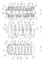
- FIGS. 1A-1Dshow perspective views of an articulating mechanism according to one embodiment of the invention, with pairs of flexible segments connected by corresponding cable sets and having flexible hinges oriented orthogonal to one another.
- FIG. 1Ashows the mechanism in its natural, unactuated configuration.
- FIGS. 1B-1Dshow the mechanism in different states of manipulation.
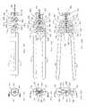
- FIG. 2Ais a perspective view of a flexible member according to another embodiment of the invention, with flexible segments having flexible hinges oriented orthogonal to one another.
- FIG. 2Bis a side view of the flexible segment of FIG. 2A .
- FIG. 2Cis a cross-sectional view of the flexible segment as shown in FIG. 2B , taken along the plane designated by line A-A.
- FIGS. 3A and 3Bare perspective and side views, respectively, of a flexible member according to yet another embodiment of the invention.
- FIG. 3Cis a cross-sectional view of the flexible member of FIG. 3A , taken along the plane designated by line B-B.
- FIGS. 4A and 4Bare perspective and side views, respectively, of a flexible segment according to a further embodiment of the invention.
- FIG. 4Cis a cross-sectional view of the flexible segment of FIG. 4A , taken along the plane designated by line C-C.
- FIGS. 5A and 5Bare perspective and side views, respectively, of a flexible segment according to yet another embodiment of the invention.
- FIG. 5Cis a cross-sectional view of the flexible segment of FIG. 5A , taken along the plane designated by line D-D.
- FIG. 6is a side sectional view of an articulating mechanism according to another embodiment of the invention, showing a scaling of movement between the proximal and distal end.
- FIG. 7is a side sectional view of an articulating mechanism according to yet another embodiment of the invention, showing a different scaling of movement between the proximal and distal end.
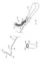
- FIG. 8Ais a perspective view of a surgical instrument incorporating a grasping tool and an articulating mechanism according to an embodiment of the invention.
- FIG. 8Bis an enlarged view of the distal end of the instrument of FIG. 8A , showing the grasping tool in greater detail.
- FIGS. 9A and 9Bshow end and cross-sectional views, respectively, of the grasping tool depicted in FIG. 8B in the closed position, with the cross-sectional view of FIG. 9B taken along the plane designated by line 9 B- 9 B in FIG. 9A .
- FIGS. 10A and 10Bshow end and cross-sectional views, respectively, of the grasping tool depicted in FIG. 8B in a first open position (with the jaws remaining parallel) with the cross-sectional view of FIG. 10B taken along the plane designated by line 10 B- 10 B in FIG. 9A .
- FIGS. 11A and 11Bshow end and cross-sectional views, respectively, of the grasping tool depicted in FIG. 8B in a second open position (with the jaws having moved to a non-parallel position) with the cross-sectional view of FIG. 10B taken along the plane designated by line 10 B- 10 B in FIG. 9A .
- FIG. 12is a perspective view of a flexible segment of yet another embodiment of the invention.
- FIG. 13is an exploded view of the flexible segment of FIG. 12 , showing the inner core and outer cover that form the flexible segment of FIG. 12 .
- FIGS. 14A and 14Bshow side and cross-sectional views, respectively, of a flexible segment according to further embodiment of the invention, in a straight, unbent configuration.
- the cross-sectional view of FIG. 14Bis taken along the line designated 14 B- 14 B in FIG. 14A .
- FIGS. 15A and 15Bshow side and cross-sectional views, respectively, of the flexible segment FIGS. 14A-14B , in a bent configuration.
- the cross-sectional view of FIG. 15Bis taken along the line designated 15 B- 15 B in FIG. 15A .
- FIG. 16Ais a perspective view of a catheter incorporating a an articulating mechanism according to an embodiment of the invention.
- FIG. 16Bis an enlarged view of the distal end of the catheter of FIG. 16A .
- Articulating mechanismsgenerally include multiple pairs of flexible segments and at least one set of cables connecting at least one discrete pair of flexible segments.
- the articulating mechanismscan be formed of flexible members that are made of flexible segments and that can have varying numbers of links.
- the term “link” as used hereinrefers to a discrete portion of the mechanism, flexible member, or flexible segment that is capable of movement relative to another discrete portion of the mechanism, flexible member or flexible segment. Links are typically, but need not be, cylindrical. The links are generally aligned along the longitudinal axis of the mechanism, flexible member or flexible segment. Adjacent links of the mechanism, flexible member or flexible segment are joined by flexible hinges.
- Terminal links of the articulating mechanism, flexible member or flexible segmentcan also be secured to or incorporated into other aspects of the mechanism or tools attached to the mechanism.
- the term “flexible hinge”refers to a discrete section that extends from a link and is capable of flexure. Flexible hinges are typically, but need not be, oriented perpendicular to the longitudinal axis of the mechanism, flexible member or flexible segment. Links and flexible hinges are typically, but not necessarily, integrally formed together.
- a “flexible segment”usually includes one or more adjacent links connected by flexible hinges. A flexible segment capable of movement in two dimensions with a single degree of freedom can have a single flexible hinge that connects two links.
- a flexible segment capable of movement in three dimensions with two degrees of freedomcan have two flexible hinges oriented at an acute angle to one another connecting to three links. For a maximum three-dimensional range of motion, the angle will be orthogonal.
- Flexible segmentscan provide the component pieces of a flexible member or of an articulating mechanism.
- a “flexible segment pair”refers to a flexible segment at one end of the mechanism that corresponds to another flexible segment at the opposite end of the mechanism.
- Articulating mechanisms according to the inventionwill include a plurality of flexible segments that are members of discrete pairs. The flexible segments are generally arranged to form a proximal end and a distal end, with one flexible segment of each pair being situated at the proximal end, and the other flexible segment at the distal end.
- at least one flexible hinge of the mechanismis oriented orthogonal to at least one other hinge of the mechanism.
- the inventionalso contemplates configurations where flexible hinges are oriented parallel or are offset at any acute angle.
- a cable setcan connect the flexible segments of a discrete pair to one another so that movement of one flexible segment of a pair causes a corresponding movement of the other flexible segment of the pair.
- active flexible segmentor “active flexible segment pair” refers to flexible segments that are directly connected to one another by a cable set.
- spacer flexible segmentor “spacer flexible segment pair” refers to flexible segments that are not directly connected by a cable set. Spacer flexible segments can nevertheless be disposed between active flexible segments and provide for the passage of cable sets that connect active flexible segments. The ability to manipulate active flexible segment pairs allows for the mechanism to readily form complex three-dimensional configurations and geometries as is further detailed herein.
- the present inventionalso allows for increased rigidity of the mechanism by constraining manipulated active flexible segments and allowing such segments to resist movement due to laterally applied forces.
- a given flexible segment pairis considered fully constrained if upon manipulating the segment pair to achieve the desired shape, and fixing one segment of the pair in that desired shape, the other segment of the pair can resist loads while maintaining its desired, unloaded shape.
- a minimum of two cablesare required to fully constrain a single degree of freedom flexible segment that has two links and one flexible hinge.
- Spacer flexible segmentswill not be so constrained, and the inclusion of such unconstrained spacer flexible segments may be advantageous in many situations where it is desirable to have portions of the actuated mechanism be less rigid.
- instrumentand “tool” are herein used interchangeably and refer to devices that are usually handled by a user to accomplish a specific purpose.
- articulating mechanisms of the inventionwill be described in the context of use for the remote guidance, manipulation and/or actuation of surgical or diagnostic tools and instruments in remote accessed regions of the body.
- other applications of the articulating mechanism besides surgical or diagnostic applicationsare also contemplated and will be apparent to one of skill in the art.
- any such applicationwill include any situation where it is desirable to navigate an instrument or tool into a workspace that is not easy to manually navigate by hand or that might otherwise present a risk or danger.
- industrial usessuch as for the navigation of a tool, probe, sensor, etc.
- articulating mechanism 100includes a plurality of flexible segments that form a proximal end 121 and a distal end 122 .
- Flexible segments 111 and 112 , 113 and 114 , 115 and 116 , 117 and 118 and 119 and 120are each members of a discrete pair, with one flexible segment of a pair ( 111 , 113 , 115 , 117 or 119 ) at proximal end 121 with the other ( 112 , 114 , 116 , 118 or 120 ) at distal end 122 .
- flexible segment 111 at proximal end 121is formed of links 101 , 103 and 105 connected by flexible hinges 107 and 109 oriented orthogonal to each other.
- Cable channels 123are located and pass through the periphery of each link for accepting passage and connection of cable sets.
- the flexible segmentalso includes central channel 124 running through the longitudinal axis of the flexible segment to accommodate additional cables, wires, fiberoptics or other like elements associated with a desired tool or instrument used in conjunction with the mechanism.
- Paired flexible segment 112 at distal end 122similarly is formed of links 102 , 104 and 106 connected by flexible hinges 108 and 110 oriented orthogonal to one another and likewise including similar cable channels and central channel.
- the remaining flexible segments of both the proximal end ( 113 , 115 , 117 and 119 ) and distal end ( 114 , 116 , 118 and 120 )have the same configuration with the last link of one segment also functioning as the first link of the next segment. And as shown, each flexible hinge is oriented orthogonal to adjacent hinges. As previously noted flexible segments of such configuration move in two degrees of freedom and are moveable in three dimensions.
- the proximal flexible segments ( 111 , 113 , 115 and 119 )are connected to the distal flexible segments ( 112 , 114 , 116 and 120 ) by sets of cables 131 , 133 , 135 and 139 , respectively. These flexible segment pairs are thus active flexible segments.
- Flexible segments 117 and 118are not directly connected by a cable set and thus function as spacer segments.
- the mechanismfurther includes spacer element 125 disposed between the proximal end 121 and the distal end 122 to provide additional separation between the proximal flexible segments and distal flexible segments.
- the spacer elementis optional, and may be of any length appropriate to the intended application. It is configured to accommodate all the cables that connect the flexible segment pairs, as well as additional cables, wires, fiberoptics or other like elements associated with a desired tool or instrument used in conjunction with the mechanism.
- Each active flexible segment at the proximal end of the articulating mechanismis connected to its corresponding active flexible segment at the distal end by two or more cables.
- Each cable setmay be made up of at least two cables.
- movement of one active flexible segment pairis controlled by its corresponding cable set and is independent of any other flexible segment pair.
- a cable setwill include three cables spaced 120 degrees apart.
- FIGS. 1A-1DBy combining a plurality of active flexible segments, multiple degrees of freedom are achieved, allowing the articulating mechanism to be shaped into various complex configurations.
- the variation shown in FIGS. 1A-1Dhas a total of four active flexible segment pairs each independently connected by sets of three cables each, for possible motion in twelve degrees of freedom.
- Such multiple degrees of freedomare not available in typical conventional mechanisms where only a single set of cables is employed to manipulate the mechanism links.
- the flexible segmentsalso include a plurality of channels for passage of the cables that connect active flexible segment pairs, as shown. Cables, wires, fiberoptics, flexible endoscopes and the like, may also be run through a central channel provided in the flexible segments, if desired. Channels can also be provided to allow for passage of fluid delivery tubes.
- the flexible segmentscan further be designed with attachment channels that communicate with the flexible segment exterior for mounting other elements, e.g., energy sources (for ablation or coagulation) or fiberoptics, or flexible endosocopes, at the distal end of the articulating mechanism. More than one flexible segment may include an attachment channel so that the attachment channel may extend from the distal end to the proximal end of the mechanism.
- cables fixed to a proximal active flexible segmenttravel through spacer 125 to connect with a corresponding distal flexible segment of the pair.
- movement of active proximal flexible segmentsresults in inverted, reciprocal movement of active distal flexible segments.
- the cablescan be twisted or rotated 180 degrees while running through spacer element 125 so that the reciprocal movement at the distal end 122 is mirrored.
- the articulating mechanisms of this inventionmay be configured to include cables twisted in any amount between 0 degrees to 360 degrees to provide for 360 degree range of reciprocal motion.
- Spacer flexible segmentsi.e., flexible segments not connected by discrete sets of cables (e.g., 117 and 118 in FIGS. 1A-1D ), may also be included in the articulating mechanisms. These flexible segments can be inserted between active flexible segments at either the proximal or distal ends or both, and act as flexible segments that are not independently actuatable, but that do allow for pass through of cable sets to neighboring active flexible segments. Spacer flexible segments can be desirable for providing additional length to the proximal and/or distal end of the mechanism. In addition the inclusion of spacer flexible segments (or a greater relative number of spacer flexible segments) at one end of the mechanism, allows for the proportional scaling of movement or motion of the corresponding other end.
- spacer flexible segmentsor a greater relative number of spacer flexible segments
- the inclusion of spacer flexible segments (or a greater relative number of spacer flexible segments) at the proximal endwould require a more exaggerated movement by the user at the proximal end to achieve the desired motion at the distal end.
- Thiscould be advantageous in situations where fine, delicate controlled movements were desired, such as, for example, situations where there is a risk that a user may not possess the necessary dexterity to perform the desired procedure absent such proportional scaling of the distal end movement or motion.
- spacer flexible segmentsor a greater relative number of spacer flexible segments
- proportional scaling of movement or motioncan also be accomplished by increasing or decreasing the cable channel pattern radius of the flexible segments, either active or spacer, at either the proximal or distal end, as will be further detailed herein.
- Complex movementsincluding up, down, right, left, oblique, and rotational movements, may be accomplished due to the formation of pairs of active flexible segments connected by discrete cable sets, as described above.
- the most distal active flexible segment 112 at the distal endmay be actuated, while all other flexible segments remain stationary, by actuation of the most proximal flexible segment 111 at the proximal end.
- Proximal segment 111can further be manipulated such that distal-most flexible segment 112 sweeps a right circular cone about longitudinal axis Z 1 of the mechanism, the base diameter of which increases with such factors as increased length of the flexible hinge, enhanced cable flexibility, and addition of spacer flexible segments between flexible segment 112 and the next adjacent active flexible segment.
- proximal segment 111can be rotated or “rolled” about its axis, represented as Z 3 in FIG. 1B , and the resultant torque transmitted through the mechanism to distal segment 112 , such that segment 112 rotates about its axis, represented as Z 2 in FIG. 1B .
- the most proximal active flexible segment at the distal end, 120is actuated while all other flexible segments remain stationary by actuating only the most distal active flexible segment at the proximal end, flexible segment 119 .
- the distal endcan sweep a right circular cone with a larger base diameter than that discussed above with respect to FIG. 1B , due to the increased number of segments distal to the actuated segment.
- the proximal endcan be rotated or “rolled” about its axis and the resultant torque transmitted through the mechanism to the distal end.
- FIG. 1Dshows the distal end 122 of articulating mechanism 100 having multiple curvatures along its length, each oriented in directions independent of one another.
- articulating mechanism 100 of FIG. 1A-1Dhas four active pairs of flexible segments, each of which is connected by a cable set having three cables, providing for movement in twelve degrees of freedom, but other configurations of flexible segment pairs and cable sets will readily achieve similar complex movements and geometries.
- the ability of portions the mechanism to bend in different directions at the same time and create active complex configurationsis provided by the independent actuation of each active flexible segment pair as controlled through its corresponding cable set.
- flexible member 200includes flexible segments 216 , 218 and 220 formed by a series of links 202 , 204 , 206 , 208 , 210 , 212 and 214 connected by flexible hinges 231 , 232 , 233 , 234 , 235 and 236 , respectively.
- the flexible memberterminates at either end at links 202 and 214 .
- Terminal link 202includes cylindrical recess 223 and hexagonal boss 225 facing away from terminal link 214 .
- Terminal link 214in turn includes hexagonal socket 224 facing away from terminal link 202 .
- flexible hinges 231 , 233 and 235are oriented orthogonal to flexible hinges 232 , 234 and 236 .
- the linksfurther include channels 228 that receive the individual cables sets that control the links.
- the memberis designed such that the cables will pass through cable channels in the links and terminate and be affixed to terminal link 202 of flexible segment 216 .
- the cablescan exit channels 228 at exit points 229 and be affixed to recess 223 of link 202 .
- Flexible segment 216then acts as an active flexible segment with the remaining flexible segments being spacer flexible segments.
- a cable setcould terminate any one of the other flexible segments, making any other flexible segment an active flexible segment.
- cable channels 228are shown arranged in a circular pattern, such a pattern is not critical, as each channel can be located at any radial location along the member.
- Center channel 227extends axially through the flexible member to accommodate additional elements of any tools or instrument associated with the flexible member or with any articulating mechanism that includes the flexible member.
- a similar channelcould be provided at any other radial location along the member, including its perimeter.
- the flexible membercan be incorporated into or form all of or a portion of the proximal and distal ends of an articulating mechanism according to the invention.
- the flexible hinge systemhas a variety of important advantages. One is ease of manufacture and assembly, as the flexible segments, flexible members, or the articulating mechanism or portions thereof can be manufactured as single continuous piece having multiple links connected by the flexible hinges. In addition, multiple flexible segments or members of the same or differing configurations can be readily connected together to create a wide variety of articulating mechanisms, the characteristics of which will depend in part on the component flexible segments or members used. In the embodiment depicted in FIGS. 2A-2C , the reciprocating boss 225 and socket 224 allow multiple flexible members to be connected to each other, but one of skill in the art will appreciate there are a variety of reciprocating structures that can achieve the same purpose. A further advantage provided by the flexible hinge system is an increased ability to transmit torque along the mechanism.
- At least one flexible hinge of the mechanism, flexible member or flexible segmentis oriented orthogonal to at least one of the other flexible hinges.
- the flexible hingesneed not be orthogonal.
- consecutive hingesare orthogonal to one another but the invention contemplates other configurations, including configurations where two or more consecutive hinges are oriented parallel to each other or are offset from each other anywhere from 0-90 degrees.
- FIGS. 3-5embodiments of flexible segments are depicted where the flexible hinges bend or flex at predetermined positions relative to the adjacent connected links.
- the linksotherwise have the same overall diameter, the same diameter or distance between cable channels, and the same gap between the links.
- the predetermined flex location between the linkscan have a positive, neutral or negative effect, or bias, on the relative tautness of cables passing through the link. More particularly, when a flexible segment bends due to an actuating force applied by a cable or cables along one side of the links of a segment, the relative tautness of cables passing through the other side of the links can be affected in a positive, negative or neutral manner.
- This effect, or biascan also be referred to as “cable pull bias.”
- Flexible segments that create or increase cable tension when the segment links are articulatedare said to have “positive bias.”
- flexible segments that result in decreased cable tension or slack when the segment links are articulatedare referred to as having a “negative bias.”
- Flexible segments that minimize cable tension and cable slackare said to have “neutral bias.”
- positive, neutral or negative effectscan be advantageous.
- the particular predetermined flex locations to achieve positive, neutral or negative cable pull biaswill depend on the particular dimensions of a given pair of links and the connecting hinge or hinges, including the diameter of the cable channel pattern, the gap between the links where cables are exposed, and the maximum flex angle of the links.
- These particular predetermined flex locationscan be measured as a particular offset (positive or negative) relative to the link surface where the cables emerge or exit from the cable channels.
- the flexible hinge between two given linksflexes or bends, such that the two links are flexing or bending toward or away from one another about the hinge.
- the distance a given cable channel exit point on one link moves towards its corresponding cable channel exit point on the other linkis equal to the distance the opposing cable channel exit point on the opposite side of the link moves away from its corresponding cable channel exit point on the other link.
- the combined distance between the two respective sets of cable channel exit pointsremains constant whether or not the segment is flexed, which is important to maintaining neutral cable bias. Where such combined distances are not equal, an increase in cable slack or tension can occur. Particularly, where the combined distance between sets of opposing channel exit points is greater when the links are flexed as compared to the combined distance in the straight, non-bent position, cable tension can occur. Alternatively, where the combined distance between sets of opposing channel exit points is lessened upon flexing or bending relative to a straight, non-bent position, cable slack can occur
- flexible segment 240includes flexible hinge 246 connecting links 244 and 245 .
- the linksalso include cable channels 248 .
- the linkshave a cable channel pattern diameter of D, and are separated by gap G between the links where cables are exposed.
- the linkshave a maximum flex angle of T about hinge 246 .
- the desired predetermined flex position for neutral cable pull biasis an offset O 1 of 1/100 D, which is practically at or near surface face 247 of link 245 where the cables emerge or exit from the cable channels.
- the flex positionis aligned or nearly aligned with the surface portion of link 245 where the cables emerge or exit.
- flexible segment 260has flexible hinge 266 with a predetermined flex position located between two adjoining links 264 and 265 .
- Links 264 and 265contain cable channels 268 .
- the flexible hingehas a positive offset O 2 relative to the surface 267 of link 265 .
- this flex positionleads to a negative cable pull bias. That is, when the segment bends at these links due to an actuating force applied by a cable or cables along one side of the links there is typically slack created in the cable or cables along the opposite side of the links.
- this creation of slackmay be desirable as it will decrease the rigidity of the device in that area, and limit its resistance to counter forces deployed along that area. Examples where this could be desirable include navigation of the mechanism through or around sensitive or fragile anatomical structures. Flexible hinges that allow for some degree of slack in the cables are said to have a “negative bias.”
- flexible segment 280includes flexible hinge 286 connecting links 284 and 285 .
- Links 284 and 285likewise include cable channels 288 .
- the flex positionhas a negative offset O 3 relative to surface 287 of link 285 . That is, the flex position is below the surface portion of link 285 where the cables emerge or exit. In the situation where dimensions D, G and T are as above, this flex position leads to a positive cable pull bias. That is, when the segment bends at these links due to an actuating force applied by a cable or cables along one side of the links there is typically tension created in the cable or cables along the opposite side of the links.
- this creation of tensionmay be desirable as it will increase the rigidity of the device in that area and resist any applied counter force. Such tension can further provide a resistance to further bending of the mechanism, and provide feedback to the user. Examples where this could be desirable include applications where it is important to guard against too much bending or “overbending” of the mechanism. Flexible hinges having this configuration that create additional tension in the cables are said to have a “positive bias.”
- FIG. 6depicts another embodiment of the invention, with articulating mechanism 300 with proximal and distal ends 321 , 322 , respectively, and spacer element 325 disposed there between.
- Distal end 322includes flexible segments 316 , 318 , 320 , 322 and 324 formed by a series of links 302 , 304 , 306 , 308 , 310 , and 312 connected by flexible hinges 317 , 319 , 321 , 323 , and 325 , respectively.
- Proximal end 321includes flexible segment 314 formed by links 301 and 303 connected by flexible hinge 315 .
- the flexible hingesare all oriented parallel to one another along the longitudinal axis of the unactuated mechanism (as represented by axis Z).
- the linksfurther include channels that receive cables 331 and 332 that form the cable set that controls actuation of the mechanism.
- the mechanismis designed such that the cables will pass through cable channels in the links.
- the cablesare secured to distal terminal link 302 of flexible segment 316 and to proximal terminal link 301 of flexible segment 314 .
- Flexible segments 316 and 314thus act as an active flexible segment pair with the remaining flexible segments being spacer flexible segments.
- FIG. 6shows articulating mechanism 300 in an actuated or manipulated condition.
- proximal flexible segment 314 at proximal end 321has been flexed about an angle of W. Due to the addition of the spacer segments at distal end 322 , the entire distal end flexes about the equivalent angle W, but the angle between each flexible segment is lessened such that the angles in the cumulative match angle W.
- the distance Y that distal end 322 travels relative to the original axis line Z of the mechanismis proportionally greater than the distance X that distal end 321 travels relative to axis Z. This illustrates how the addition (or subtraction) of spacer segments can result in achieving same overall angle of bend but across a greater (or lesser) lateral distance.
- FIG. 7depicts further embodiment of the invention, with articulating mechanism 350 having proximal and distal ends 371 , 372 , respectively separated by spacer element 375 .
- Distal end 372includes flexible segment 362 formed of links 352 and 354 connected by flexible hinge 356 .
- Proximal end 371includes flexible segment 361 formed by links 351 and 353 connected by flexible hinge 355 .
- the linksfurther include channels that receive cables 381 and 382 that form the cable set that controls actuation of the mechanism. Again, the mechanism is designed such that the cables will pass through cable channels in the links.
- the cablesare secured to distal terminal link 352 of flexible segment 362 and to proximal terminal link 351 of flexible segment 361 .
- Flexible segments 362 and 361thus act as an active flexible segment pair.
- the diameter K between cable channels of links 351 and 353 at the proximal endis larger than diameter J of corresponding links 352 and 354 at the distal end.
- articulating mechanism 350in an actuated or manipulated condition.
- proximal flexible segment 361 at proximal end 371has been flexed about an angle of H.
- distal flexible segment 362flexes about a larger angle of P. This is due to the change in diameter between cable channels between the proximal and distal links.
- the change in flex angleis generally proportional to the diameter differences, with angle P being proportional to angle H multiplied by the ratio of the two diameters (i.e., P ⁇ H ⁇ (K/J)). For any two link pairs then, the difference can be expressed in terms of the resulting pivot angle that results when the links are manipulated relative to their unpivoted state.
- the linksmay further be of any size and shape, as the purpose dictates.
- the size and shape of linksusually depends on such factors as patient age, anatomy of the region of interest, intended application, and surgeon preference.
- Linksare generally, but need not be, cylindrical, and as previously mentioned include channels for passage of the cables that connect the flexible segment pairs as well as additional cables, wires, fiberoptics or other like elements associated with a desired tool or instrument used in conjunction with the mechanism.
- the channel diametersare usually slightly larger than the cable diameters, creating a slip fit.
- the linksmay also include one or more channels for receiving elements of attachable surgical instruments or diagnostic tools or for passage of cables that actuate them.
- the linksmay typically have a diameter from about 0.5 mm to about 15 mm or more depending on the application.
- representative diametersmay range from about 2 mm to about 3 mm for small endoscopic instruments, about 5 mm to about 7 mm for mid-sized endoscopic instruments, and about 10 mm to about 15 mm for large endoscopic instruments.
- the diametermay range from about 1 mm to about 5 mm.
- Overall length of the linkswill vary, usually depending on the bend radius desired between links.
- the articulating mechanism, flexible members and flexible segmentsmay be formed of a number of materials known in the art and that can vary according to the application.
- injection moldable polymerscan be used including, e.g., polyethylene or copolymers thereof, polyethylene terephthalate or copolymers thereof, nylon, silicone, polyurethanes, fluoropolymers, poly (vinylchloride); and combinations thereof, or other suitable materials known in the art.
- a lubricious coatingmay be placed on the links or segments if desired to facilitate advancement of the articulating mechanism.
- the lubricious coatingmay include hydrophilic polymers such as polyvinylpyrrolidone, fluoropolymers such as tetrafluoroethylene, or silicones.
- a radioopaque markermay also be included on one or more segments to indicate the location of the articulating mechanism upon radiographic imaging. Usually, the marker will be detected by fluoroscopy.
- Cable diametersvary according to the application. For surgical applications in general, cable diameters and may range from about 0.15 mm to about 3 mm. For catheter applications, a representative diameter may range from about 0.15 mm to about 0.75 mm. For endoscopic applications, a representative diameter may range from about 0.5 mm to about 3 mm.
- Cable flexibilitymay be varied, for instance, by the type and weave of cable materials or by physical or chemical treatments. Usually, cable stiffness or flexibility will be modified according to that required by the intended application of the articulating mechanism.
- the cablesmay be individual or multi-stranded wires made from material, including but not limited to biocompatible materials such as nickel-titanium alloy, stainless steel or any of its alloys, superelastic alloys, carbon fibers, polymers, e.g., poly (vinylchloride), polyoxyethylene, polyethylene terephthalate and other polyesters, polyolefin, polypropylene, and copolymers thereof; nylon; silk; and combinations thereof, or other suitable materials known in the art.
- biocompatible materialssuch as nickel-titanium alloy, stainless steel or any of its alloys, superelastic alloys, carbon fibers, polymers, e.g., poly (vinylchloride), polyoxyethylene, polyethylene terephthalate and other polyesters, polyolefin, polypropy
- the cablesmay be affixed to the flexible segments of an active pair according to ways known in the art, such as by using an adhesive or by brazing, soldering, welding, and the like, including methods described in pending and co-owned U.S. application Ser. Nos. 10/444,769 and 10/928,479, incorporated herein by reference in their entirety.
- the natural configuration of the articulating mechanisms, flexible members or flexible segmentsis usually linear, although if desirable the mechanisms, flexible members or flexible segments can be manufactured to have a pre-formed bend. If maintenance of a certain curvature or other complex configuration is desired at the distal end of the articulating mechanism, the mechanism can be “locked” into place according to ways described e.g. in pending and co-owned U.S. application Ser. Nos. 10/444,769 and 10/928,479, incorporated herein by reference in their entirety.
- a malleable tube slidable over the proximal segmentsmay be shaped to keep the proximal segments, and thus, their corresponding distal segments in a particular configuration.
- a userhas navigated the mechanism to a desired target location and wishes to “lock” the mechanism in place while e.g. actuating a tool associated with the mechanism, or engaging in a separate procedure altogether.
- a locking rodmay be inserted into one or more attachment channels extending through the flexible segments or segments to “lock” the proximal and distal segments of the articulating mechanism in place.
- the locking rodmay be a malleable metal bar that may be shaped and then inserted into the attachment channels to set the proximal and distal segments into a particular configuration, or the locking rods may be provided in preshaped forms.
- the flexible segments or members themselvesmay be formed of a malleable material that retains its shape once manipulated into the desired configuration.
- the articulating mechanisms of this inventionmay be used to direct a surgical or diagnostic instrument tool within a body region or to a target site within a body region of a patient either in its native, straight configuration, or after undergoing various manipulations at its proximal end from a location outside the patient.
- movement of the proximal end of the mechanismresults in reciprocal movement at the distal end.
- the resulting directional movement of the distal endcan be inverted, mirrored or otherwise, depending on the degree of rotation of the proximal end relative to the distal end.
- the proximal endprovides for a user interface to control the steering and manipulation of the distal end that is convenient and easy to use relative to other conventional steering mechanisms that rely on e.g., pulleys or knobs to control steering wires.
- This user interfaceallows for example a user to readily visualize the shape and directional movement of distal end of the mechanism that is located e.g. within a patient based on the manipulated shape of the externally positioned proximal end user interface.
- the flexible segments or members themselvesmay be formed of a malleable material that retains its shape once manipulated into the desired configuration.
- the articulating mechanismmay be employed for remote manipulation of surgical instruments, diagnostic tools, various catheters, and the like, into hollow or chambered organs and/or tissues including, but not limited to, blood vessels (including intracranial vessels, large vessels, peripheral vessels, coronary arteries, aneurysms), the heart, esophagus, stomach, intestines, bladder, ureters, fallopian tubes, ducts such as bile ducts, and large and small airways.
- the articulating mechanismmay also be used to remotely direct surgical instruments, diagnostic tools, various catheters, and the like, to solid organs or tissues including, but not limited to, skin, muscle, fat, brain, liver, kidneys, spleen, and benign or malignant tumors.
- the articulating mechanismmay be used in mammalian subjects, including humans (mammals include, but are not limited to, primates, farm animals, sport animals, cats, dogs, rabbits, mice, and rats).
- FIGS. 8-12an embodiment of the invention is depicted which incorporates an articulating mechanism with flexible segments into a surgical instrument.
- FIG. 8Aillustrates a surgical grasping instrument 400 which includes an elongate shaft 405 which separates proximal and distal flexible members 406 and 407 , respectively.
- the flexible membersare as described above, with multiple cables associated with discrete flexible segments such that movement of the proximal end results in corresponding movement of the distal end.
- Actuating handle 402is located at the proximal end of proximal flexible member 406 , and has a standard ratchet handle interface with pivoting arms 403 and 404 that are pivotable toward and away from one another.
- grasping tool 410includes upper and lower jaws 412 and 414 that are connected to jaw housing 416 , with base 418 of housing 416 being fixedly secured to the distal end of distal flexible member 407 .
- jaw housing 416includes opposed parallel extending walls 420 and 422 with the proximal ends of jaws 412 and 414 positioned between the walls.
- each jawincludes slots that receive pins that span the space between the two walls.
- upper jaw 412includes slots 452 and 456 that receive pins 423 and 424 , respectively.
- Lower jaw 414includes slots 454 and 458 that receive pins 425 and 426 .
- the slots of each jaware oriented at an angle relative to the distal grasping portion of the jaws and are generally parallel to one another over most of the length of each slot. As can be seen however with particular reference to FIGS.
- both slots 452 and 454have proximal terminal portions 453 and 455 respectively that diverge from parallel relative to respective slots 456 and 458 . This will have an important impact on jaw movement as further discussed below.
- Jaws 412 and 414also include notches 457 and 459 , with notch 457 located between slots 452 and 456 on jaw 412 and notch 459 located between slots 454 and 458 on jaw 414 . These notches 457 and 459 accommodate pins 424 and 426 , respectively, when the jaws are in the closed position (see FIG. 9B ).
- Jaws 412 and 414are also pivotally connected to link arms 436 and 438 , respectively, which in turn are pivotally connected at their other ends to cable terminator 430 , which likewise resides within housing 416 and between walls 420 and 422 .
- Actuating cable 432is connected to and terminates at cable terminator 430 with cable 432 itself extending proximally through the jaw housing 416 and through a central channel (not shown) that extends through flexible member 407 , elongate shaft 405 , and terminates at its other end at arm 404 of handle 402 .
- Bias spring 434is aligned axially with cable 432 and is disposed between cable terminator 430 and base 418 of jaw housing 415 .
- Jaws 412 and 414themselves include opposing jaw surfaces 442 and 444 , respectively. The jaw surfaces are each provided with channels 446 and 448 respectively that can receive e.g. an energy source suitable for ablating tissue.
- the configuration of the jaw and jaw housing connectionprovides important advantages as it allows for parallel movement of the jaws over a first range of motion while further allowing for the jaws to diverge in a non-parallel fashion over a second range of motion.
- This overall range of motioncan be observed by reference to FIGS. 9-11 , with the jaws able to move from a closed position ( FIGS. 9A-9B ) to a first open position ( FIGS. 10A-10B ) while remaining parallel to each other at all times during such movement. From this first open position, the jaws can then move in a non-parallel fashion to a second open position ( FIGS. 11A-11B ).
- the distal tips of the jawshave diverged further from one another relative to the proximal ends of the jaws, creating a larger opening between the jaws at the tips, similar to what occurs with jaws that are connected by a single pivot.
- This larger openingis advantageous as it facilitates navigating the jaws around target tissue or anatomy.
- the jawsmaintain a parallel movement relative to each other upon closing from the first open position ( FIGS. 10A-10B ) to the closed position ( FIGS. 9A-9B ), which provides a variety of advantages, including an even force distribution across the jaws as they are closed upon target tissue.
- an energy sourceis attached to the jaws for e.g. ablation
- the parallel movement of the jawsallows for a more uniform transfer of energy to the tissue along the length of the jaws, providing more uniform and consistent ablation.
- bias spring 434is positioned to continually bias the jaws apart from each other in the open position.
- the spring biascan be overcome by actuating handle 402 to translate cable 432 and connected cable terminator 430 toward the proximal end of the instrument, bringing the jaws into the closed position depicted in FIGS. 9A-9B .
- tension on the cableis released, the jaws are biased open from the closed position to the first open position ( FIGS.
- the jawsremain parallel as upper and lower jaws 412 and 414 translate in directions parallel to slots 452 , 456 and 454 , 458 , respectively, as slots 452 , 456 and 454 , 458 translate relative to pins 423 , 424 and 425 , 426 , respectively.
- the terminal ends of link arms 436 and 438 that are coupled to cable terminator 430also translate, but any force exerted by the link arms that would result in non-parallel movement is overcome by the restraining force of pins 423 , 424 and 425 , 426 retained in parallel slots 452 , 456 and 454 , 458 , respectively.
- pins 423 and 425relatively translate into the terminal portions 453 and 455 of slots 452 and 454 , respectively, which diverge from parallel relative to respective slots 456 and 458 . Relative movement of the pins into these non-parallel portions allows link arms 436 and 438 to pivot as well as translate, resulting in the divergent movement of jaws 412 and 414 relative to each other as the jaws move to the second open position ( FIGS. 11A-11B ).
- catheter 700incorporates an articulating mechanism with the distal end of the mechanism 702 integral with the distal end of the catheter, and the proximal end formed of flexible member 704 extending from handle 706 .
- Proximal end flexible member 704is formed of flexible segments 711 , 713 and 715 similar to those described herein.
- Distal end sections 712 , 714 , and 716are integrally formed sections of the distal end 702 of the catheter.
- the distal end of catheter 700includes a catheter tube with a central lumen 724 and multiple cable channels 728 that extend the length of the catheter and that can receive cable sets (not shown) that connect the distal and proximal segments.
- the central lumencan provide passage for e.g., wires, energy sources, or other control elements to the catheter tip, or function as through lumen for the passage of fluids, or can otherwise provide for known functions of catheter lumens.
- the cablescan be anchored within the catheter tube at the desired locations as described in pending and co-owned U.S. application Ser. No. 10/444,769, incorporated herein by reference in its entirety.
- Each distal end segment of the cathetercan be formed of material having a different durometer and/or can be of varying lengths, which can provide an additional level of control when manipulating the catheter.
- the distal end segmentscan be formed of discrete sections of catheter tube material that abut one another and which are maintained in position relative to one another by the passage and affixing of the cable sets within the sections.
- catheter 700includes proximal end flexible member 704 formed of flexible segments as described herein, it is further contemplated that the proximal end can alternatively be formed of a wide variety of articulating link systems that are similarly connected to the distal end through cable sets. Such articulating link systems include, but are not limited to, those described in pending and commonly owned U.S. application Ser. Nos. 10/444,769 and 10/928,479, incorporated herein by reference in their entirety.
- FIGS. 12-13depict a flexible segment according to another embodiment of the invention.
- flexible segment 500includes two flexible hinges 506 and 508 that connect links 502 and 504 , and otherwise shares many features of the previously described flexible segments.
- Cable channels 512are provided for passage and receipt of cables for controlling the segment itself or other segments.
- Central channel 510is also provided.
- flexible segment 500is formed of two components, inner core 520 and outer cover 540 . The provision of a flexible segment formed of inner core and outer cover components provides manufacturing advantages, as will be further described.
- Inner core 520is configured to be received axially within outer cover 540 .
- Inner core 520includes link sections 522 and 524 that are each generally cylindrical.
- Flexible hinge sections 526 and 528connect each link section to wing sections 534 and 536 which together form another generally cylindrical portion aligned with and disposed between the two link sections, and which when combined with the link sections provide for central channel 510 of the formed flexible segment 500 .
- the inner corealso includes alignment flanges 530 and 532 that extend lengthwise along the outer surface of the core.
- Outer cover 540likewise includes link sections 542 and 544 that are also generally cylindrical.
- Flexible hinge section 546 and 548connect each link section to stem sections 554 and 556 which are aligned with and disposed between the two link sections. Extending lengthwise along the interior surface of outer cover 549 is a series of cable slots 558 .
- the outer cover 540also includes alignment slots 550 and 552 that extend lengthwise along the interior surface of the cover, with slots 550 in particular extending along stems sections 554 and 556 . These slots receive alignment flanges 530 and 532 respectively of inner core 520 , such that when the inner core and outer cover are assembled together, the respective link sections and flexible hinge sections of the inner core and outer cover are in alignment with each other to form the links and flexible hinges of the formed flexible segment 500 , as well as forming cable channels 512 .
- link sections 522 and 542form link 502
- flexible hinge sections 526 and 546form flexible hinge 506
- flexible hinge sections 528 and 548form flexible hinge 508
- link sections 524 and 544form link 504 .
- the outer surface of inner core 520abuts the inner surface of outer cover 540 , sealing off cable slots 558 lengthwise, and thereby forming cable channels 512 .
- an inner core and outer cover componentscan be simpler and more economical process than manufacturing the flexible segments or members as a single component.
- molding flexible segments having cable channels as a single componentrequires the use of many small core-pins that run the entire length of the part as part of molding process.
- Molding outer cover components with cable slotsis a simpler process, with the mold cavity itself providing for the slots.
- FIGS. 12-13is a dual or double flex hinge link segment, it can be easily appreciated that a wide variety of flexible hinge links, segments, and flexible members can be formed from inner core and outer cover components, including but not limited to the other links, segments and members described herein. Additionally, other links and link systems can similarly be formed of inner core and outer cover components.
- flexible segment 500also achieves other advantages.
- the dual hinge configuration of flexible segment 500also provides for neutral cable bias, similar to the fashion provided by neutral cable bias dual-pivoting link systems described in pending and commonly owned U.S. application Ser. No. 10/928,479, incorporated herein by reference in its entirety.
- each flexible hingeflexes or bends, such that the two links are flexing or bending toward or away from one another about the dual hinges. Further, as a result of such dual flexing action, the distance a given cable channel exit point on one link moves towards its corresponding cable channel exit point on the other link is equal to the distance the opposing cable channel exit point on the opposite side of the link moves away from its corresponding cable channel exit point on the other link, similar to neutral cable bias flexible segments described above. The combined distance between the two respective sets of cable channel exit points, however, remains constant whether or not the segment is flexed, which is important to maintaining neutral cable bias.
- flexible segment 500includes wing sections 536 and 534 , which can function as stops to prevent overflexing of the hinge regions.
- wing sections 536 and 534can function as stops to prevent overflexing of the hinge regions.
- opposing sides of links 502 and 504will move toward each other until they contact one or the other wing section, restricting further bending movement.
- the wing sectionswould be configured to limit each flexible hinge to a maximum of 30 degrees.
- FIGS. 14-15depict flexible segment 600 , which is similar to flexible segment 500 but is of single unit construction. Similar to flexible segment 500 , flexible segment 600 includes two links 602 and 604 connected by flexible hinges 606 and 608 .
- Cable channels 612are provided for passage and receipt of cables and central channel 610 is also provided. More specifically, flexible hinges 606 and 608 connect links 602 and 604 , respectively, to wing sections 624 and 626 disposed between and aligned with the two links. Stem sections 614 and 616 , which extend longitudinally from the wing sections, are also connected to and aligned with links 602 and 604 . As depicted most clearly in FIG. 15B , wing section 624 acts as a stop to limit further bending of flexible segment 600 .
- kits for providing various articulating mechanisms and associated accessoriesmay be provided.
- kits containing articulating mechanisms having different lengths, different segment diameters, and/or different types of tools or instrumentsmay be provided.
- the kitsmay optionally include different types of locking rods or malleable coverings.
- the kitsmay be further tailored for specific applications.
- kits for surgical applicationcan be configured for, e.g., endoscopy, retraction, or catheter placement, and/or for particular patient populations, e.g., pediatric or adult.
Landscapes
- Health & Medical Sciences (AREA)
- Life Sciences & Earth Sciences (AREA)
- Biomedical Technology (AREA)
- Animal Behavior & Ethology (AREA)
- General Health & Medical Sciences (AREA)
- Public Health (AREA)
- Heart & Thoracic Surgery (AREA)
- Veterinary Medicine (AREA)
- Engineering & Computer Science (AREA)
- Surgery (AREA)
- Biophysics (AREA)
- Pulmonology (AREA)
- Anesthesiology (AREA)
- Hematology (AREA)
- Medical Informatics (AREA)
- Molecular Biology (AREA)
- Nuclear Medicine, Radiotherapy & Molecular Imaging (AREA)
- Physics & Mathematics (AREA)
- Radiology & Medical Imaging (AREA)
- Pathology (AREA)
- Optics & Photonics (AREA)
- Ophthalmology & Optometry (AREA)
- Surgical Instruments (AREA)
- Endoscopes (AREA)
- Instruments For Viewing The Inside Of Hollow Bodies (AREA)
- Pivots And Pivotal Connections (AREA)
Abstract
Description
Claims (13)
Priority Applications (15)
| Application Number | Priority Date | Filing Date | Title |
|---|---|---|---|
| US10/948,911US7678117B2 (en) | 2004-06-07 | 2004-09-24 | Articulating mechanism with flex-hinged links |
| EP05754538.6AEP1768542B1 (en) | 2004-06-07 | 2005-05-23 | Articulating mechanism with flex-hinged links |
| EP15173441.5AEP2949262B1 (en) | 2004-06-07 | 2005-05-23 | Articulating mechanism with flex-hinged links |
| CN201210352592.4ACN102871636B (en) | 2004-06-07 | 2005-05-23 | There is the linkwork of flex-hinged chain link |
| PCT/US2005/018145WO2005120326A2 (en) | 2004-06-07 | 2005-05-23 | Articulating mechanism with flex-hinged links |
| EP13156020.3AEP2596742B8 (en) | 2004-06-07 | 2005-05-23 | Articulating mechanism with flex-hinged links |
| JP2007527558AJP5004799B2 (en) | 2004-06-07 | 2005-05-23 | Articulation mechanism with links connected by flexible hinges |
| CN2005800251530ACN101048101B (en) | 2004-06-07 | 2005-05-23 | Articulation mechanism with flexibly articulated links |
| US12/725,377US8323297B2 (en) | 2004-06-07 | 2010-03-16 | Articulating mechanism with flex-hinged links |
| JP2012026796AJP5383837B2 (en) | 2004-06-07 | 2012-02-10 | Articulation mechanism with links connected by flexible hinges |
| US13/667,755US9095253B2 (en) | 2004-06-07 | 2012-11-02 | Articulating mechanism with flex hinged links |
| JP2013171138AJP2014000436A (en) | 2004-06-07 | 2013-08-21 | Articulation movement mechanism including link connected by flexible hinge |
| US14/753,950US9861786B2 (en) | 2004-06-07 | 2015-06-29 | Articulating mechanism with flex hinged links |
| US15/843,855US10729885B2 (en) | 2004-06-07 | 2017-12-15 | Articulating mechanism with flex-hinged links |
| US16/912,088US11491310B2 (en) | 2004-06-07 | 2020-06-25 | Articulating mechanism with flex-hinged links |
Applications Claiming Priority (2)
| Application Number | Priority Date | Filing Date | Title |
|---|---|---|---|
| US57775704P | 2004-06-07 | 2004-06-07 | |
| US10/948,911US7678117B2 (en) | 2004-06-07 | 2004-09-24 | Articulating mechanism with flex-hinged links |
Related Child Applications (1)
| Application Number | Title | Priority Date | Filing Date |
|---|---|---|---|
| US12/725,377ContinuationUS8323297B2 (en) | 2004-06-07 | 2010-03-16 | Articulating mechanism with flex-hinged links |
Publications (2)
| Publication Number | Publication Date |
|---|---|
| US20050273085A1 US20050273085A1 (en) | 2005-12-08 |
| US7678117B2true US7678117B2 (en) | 2010-03-16 |
Family
ID=34971052
Family Applications (6)
| Application Number | Title | Priority Date | Filing Date |
|---|---|---|---|
| US10/948,911Expired - LifetimeUS7678117B2 (en) | 2004-06-07 | 2004-09-24 | Articulating mechanism with flex-hinged links |
| US12/725,377Expired - Fee RelatedUS8323297B2 (en) | 2004-06-07 | 2010-03-16 | Articulating mechanism with flex-hinged links |
| US13/667,755Expired - LifetimeUS9095253B2 (en) | 2004-06-07 | 2012-11-02 | Articulating mechanism with flex hinged links |
| US14/753,950Expired - LifetimeUS9861786B2 (en) | 2004-06-07 | 2015-06-29 | Articulating mechanism with flex hinged links |
| US15/843,855Expired - LifetimeUS10729885B2 (en) | 2004-06-07 | 2017-12-15 | Articulating mechanism with flex-hinged links |
| US16/912,088Expired - LifetimeUS11491310B2 (en) | 2004-06-07 | 2020-06-25 | Articulating mechanism with flex-hinged links |
Family Applications After (5)
| Application Number | Title | Priority Date | Filing Date |
|---|---|---|---|
| US12/725,377Expired - Fee RelatedUS8323297B2 (en) | 2004-06-07 | 2010-03-16 | Articulating mechanism with flex-hinged links |
| US13/667,755Expired - LifetimeUS9095253B2 (en) | 2004-06-07 | 2012-11-02 | Articulating mechanism with flex hinged links |
| US14/753,950Expired - LifetimeUS9861786B2 (en) | 2004-06-07 | 2015-06-29 | Articulating mechanism with flex hinged links |
| US15/843,855Expired - LifetimeUS10729885B2 (en) | 2004-06-07 | 2017-12-15 | Articulating mechanism with flex-hinged links |
| US16/912,088Expired - LifetimeUS11491310B2 (en) | 2004-06-07 | 2020-06-25 | Articulating mechanism with flex-hinged links |
Country Status (5)
| Country | Link |
|---|---|
| US (6) | US7678117B2 (en) |
| EP (3) | EP1768542B1 (en) |
| JP (3) | JP5004799B2 (en) |
| CN (1) | CN102871636B (en) |
| WO (1) | WO2005120326A2 (en) |
Cited By (60)
| Publication number | Priority date | Publication date | Assignee | Title |
|---|---|---|---|---|
| US20070118097A1 (en)* | 2005-11-18 | 2007-05-24 | Steven Miller | System and method for influencing an anatomical structure |
| US20080015631A1 (en)* | 2006-07-11 | 2008-01-17 | Woojin Lee | Surgical instrument |
| US20080214897A1 (en)* | 2005-02-14 | 2008-09-04 | Shigeki Matsuo | Flexible Tube for Endoscope and Endoscope Device |
| US20080262538A1 (en)* | 2003-05-23 | 2008-10-23 | Novare Surgical Systems, Inc. | Articulating instrument |
| US20090069632A1 (en)* | 2007-09-10 | 2009-03-12 | Boston Scientific Scimed, Inc. | Medical instrument with a deflectable distal portion |
| US20090138025A1 (en)* | 2007-05-04 | 2009-05-28 | Hansen Medical, Inc. | Apparatus systems and methods for forming a working platform of a robotic instrument system by manipulation of components having controllably rigidity |
| US20090171161A1 (en)* | 2007-12-10 | 2009-07-02 | Usgi Medical, Inc. | Steerable endoscopic instruments |
| US20100234831A1 (en)* | 2004-06-07 | 2010-09-16 | Hinman Cameron D | Articulating mechanism with flex-hinged links |
| US20100249759A1 (en)* | 2004-06-07 | 2010-09-30 | Cameron Dale Hinman | Link systems and articulation mechanisms for remote manipulation of surgical of diagnostic tools |
| US20110184459A1 (en)* | 2008-08-04 | 2011-07-28 | Malkowski Jaroslaw T | Articulating Surgical Device |
| US8074859B2 (en) | 2010-03-31 | 2011-12-13 | Tyco Healthcare Group Lp | Surgical instrument |
| US8105350B2 (en) | 2006-05-23 | 2012-01-31 | Cambridge Endoscopic Devices, Inc. | Surgical instrument |
| US20120123409A1 (en)* | 2009-03-27 | 2012-05-17 | Micron Shiga, Inc | Medical treatment device |
| US20120143173A1 (en)* | 2010-12-02 | 2012-06-07 | Steege Adam T C | Surgical tool |
| US20130046523A1 (en)* | 2009-08-18 | 2013-02-21 | Paul Van Dinther | Endoscope Simulator |
| US8568444B2 (en) | 2008-10-03 | 2013-10-29 | Covidien Lp | Method of transferring rotational motion in an articulating surgical instrument |
| US8578810B2 (en) | 2011-02-14 | 2013-11-12 | Intuitive Surgical Operations, Inc. | Jointed link structures exhibiting preferential bending, and related methods |
| US8603135B2 (en)* | 2011-07-20 | 2013-12-10 | Covidien Lp | Articulating surgical apparatus |
| US20140023428A1 (en)* | 2012-07-20 | 2014-01-23 | Boston Scientific Scimed, Inc. | Elongate medical device with articulating portion |
| US20140058363A1 (en)* | 2009-07-27 | 2014-02-27 | Gerry Berkelaar | Endoscopic Surgical Instrument |
| US20140276966A1 (en)* | 2013-03-14 | 2014-09-18 | C.R. Bard, Inc. | Articulating surgical instruments |
| US8840639B2 (en) | 2010-10-29 | 2014-09-23 | Covidien Lp | Apparatus for performing an electrosurgical procedure |
| WO2015057990A1 (en)* | 2013-10-18 | 2015-04-23 | Intuitive Surgical Operations, Inc. | Wrist mechanism for surgical instrument |
| US9055960B2 (en) | 2010-11-15 | 2015-06-16 | Intuitive Surgical Operations, Inc. | Flexible surgical devices |
| US9072427B2 (en) | 2003-05-23 | 2015-07-07 | Intuitive Surgical Operations, Inc. | Tool with articulation lock |
| US9161771B2 (en) | 2011-05-13 | 2015-10-20 | Intuitive Surgical Operations Inc. | Medical instrument with snake wrist structure |
| US9211134B2 (en) | 2012-04-09 | 2015-12-15 | Carefusion 2200, Inc. | Wrist assembly for articulating laparoscopic surgical instruments |
| US9357984B2 (en) | 2013-04-23 | 2016-06-07 | Covidien Lp | Constant value gap stabilizer for articulating links |
| US9364222B2 (en) | 2007-05-01 | 2016-06-14 | Covidien Lp | Powered surgical stapling device platform |
| US9700334B2 (en) | 2004-11-23 | 2017-07-11 | Intuitive Surgical Operations, Inc. | Articulating mechanisms and link systems with torque transmission in remote manipulation of instruments and tools |
| US9889273B2 (en) | 2011-01-06 | 2018-02-13 | W. L. Gore & Associates, Inc. | Methods and apparatus for an adjustable stiffness catheter |
| US10213919B2 (en)* | 2015-03-23 | 2019-02-26 | Rolls-Royce Plc | Flexible tools and apparatus for machining objects |
| US10582975B2 (en) | 2015-10-16 | 2020-03-10 | Medical Microinstruments S.p.A. | Surgical tool |
| US10583270B2 (en) | 2016-03-14 | 2020-03-10 | Covidien Lp | Compound curve navigation catheter |
| US10709517B2 (en) | 2018-01-16 | 2020-07-14 | Multi Scopic Instruments, Llc | End effector |
| US10792060B2 (en) | 2017-03-14 | 2020-10-06 | Gyrus Acmi, Inc. | Instrument with a controlled jaw movement |
| US10898105B2 (en)* | 2016-06-06 | 2021-01-26 | Temple University—Of the Commonwealth System of Higher Education | Magnetometer surgical device |
| US10960182B2 (en) | 2016-02-05 | 2021-03-30 | Board Of Regents Of The University Of Texas System | Steerable intra-luminal medical device |
| US10973592B2 (en) | 2017-03-09 | 2021-04-13 | Memie Innovative Surgery Ltd. | Control console for surgical device with mechanical arms |
| US11097430B2 (en)* | 2017-10-31 | 2021-08-24 | Worcester Polytechnic Institute | Robotic gripper member |
| US11116589B2 (en) | 2014-09-04 | 2021-09-14 | Memic Innovative Surgery Ltd. | Control of device including mechanical arms |
| WO2022003659A1 (en)* | 2020-06-29 | 2022-01-06 | T.A.G. Medical Devices - Agriculture Cooperative Ltd. | Working channel device |
| US20220053996A1 (en)* | 2005-08-30 | 2022-02-24 | Boston Scientific Scimed, Inc. | Method for forming an endoscope articulation joint |
| US11478234B2 (en) | 2018-03-25 | 2022-10-25 | T.A.G. Medical Products Corporation Ltd. | Working channel device for an endoscopic tool |
| US11504144B2 (en) | 2016-02-05 | 2022-11-22 | Board Of Regents Of The University Of Texas System | Surgical apparatus |
| US11576563B2 (en) | 2016-11-28 | 2023-02-14 | Adaptivendo Llc | Endoscope with separable, disposable shaft |
| US11622675B2 (en) | 2019-05-15 | 2023-04-11 | Boston Scientific Scimed, Inc. | Medical device having asymmetric bending |
| US11723728B2 (en) | 2015-09-04 | 2023-08-15 | Momentis Surgical Ltd. | Actuation of a device comprising mechanical arms |
| US11723636B2 (en)* | 2013-03-08 | 2023-08-15 | Auris Health, Inc. | Method, apparatus, and system for facilitating bending of an instrument in a surgical or medical robotic environment |
| US11771511B2 (en) | 2016-03-09 | 2023-10-03 | Momentis Surgical Ltd | Modular device comprising mechanical arms |
| US11779410B2 (en) | 2017-03-09 | 2023-10-10 | Momentis Surgical Ltd | Control console including an input arm for control of a surgical mechanical arm |
| US11865702B2 (en) | 2017-10-31 | 2024-01-09 | Worcester Polytechnic Institute | Robotic gripper member |
| USD1018844S1 (en) | 2020-01-09 | 2024-03-19 | Adaptivendo Llc | Endoscope handle |
| US11950871B2 (en) | 2018-01-16 | 2024-04-09 | Multi Scopic Instruments, Llc | End effector |
| USD1031035S1 (en) | 2021-04-29 | 2024-06-11 | Adaptivendo Llc | Endoscope handle |
| US12048819B2 (en) | 2018-07-19 | 2024-07-30 | Ip2Ipo Innovations Limited | Method of fabricating a surgical device |
| US12082839B2 (en) | 2018-03-25 | 2024-09-10 | T.A.G. Medical Products Corporation Ltd. | Working channel device |
| USD1051380S1 (en) | 2020-11-17 | 2024-11-12 | Adaptivendo Llc | Endoscope handle |
| USD1066659S1 (en) | 2021-09-24 | 2025-03-11 | Adaptivendo Llc | Endoscope handle |
| USD1070082S1 (en) | 2021-04-29 | 2025-04-08 | Adaptivendo Llc | Endoscope handle |
Families Citing this family (301)
| Publication number | Priority date | Publication date | Assignee | Title |
|---|---|---|---|---|
| US20050245789A1 (en) | 2003-04-01 | 2005-11-03 | Boston Scientific Scimed, Inc. | Fluid manifold for endoscope system |
| US8118732B2 (en) | 2003-04-01 | 2012-02-21 | Boston Scientific Scimed, Inc. | Force feedback control system for video endoscope |
| US7578786B2 (en) | 2003-04-01 | 2009-08-25 | Boston Scientific Scimed, Inc. | Video endoscope |
| US20040199052A1 (en) | 2003-04-01 | 2004-10-07 | Scimed Life Systems, Inc. | Endoscopic imaging system |
| US7591783B2 (en) | 2003-04-01 | 2009-09-22 | Boston Scientific Scimed, Inc. | Articulation joint for video endoscope |
| US8182417B2 (en) | 2004-11-24 | 2012-05-22 | Intuitive Surgical Operations, Inc. | Articulating mechanism components and system for easy assembly and disassembly |
| US7090637B2 (en) | 2003-05-23 | 2006-08-15 | Novare Surgical Systems, Inc. | Articulating mechanism for remote manipulation of a surgical or diagnostic tool |
| US8562640B2 (en) | 2007-04-16 | 2013-10-22 | Intuitive Surgical Operations, Inc. | Tool with multi-state ratcheted end effector |
| DE10340178B3 (en)* | 2003-09-01 | 2005-04-07 | Hilti Ag | power tool |
| US7338513B2 (en)* | 2003-10-30 | 2008-03-04 | Cambridge Endoscopic Devices, Inc. | Surgical instrument |
| US7686826B2 (en)* | 2003-10-30 | 2010-03-30 | Cambridge Endoscopic Devices, Inc. | Surgical instrument |
| US7147650B2 (en)* | 2003-10-30 | 2006-12-12 | Woojin Lee | Surgical instrument |
| US7842028B2 (en)* | 2005-04-14 | 2010-11-30 | Cambridge Endoscopic Devices, Inc. | Surgical instrument guide device |
| US8100822B2 (en) | 2004-03-16 | 2012-01-24 | Macroplata Systems, Llc | Anoscope for treating hemorrhoids without the trauma of cutting or the use of an endoscope |
| US7597662B2 (en) | 2004-09-30 | 2009-10-06 | Boston Scientific Scimed, Inc. | Multi-fluid delivery system |
| US8083671B2 (en) | 2004-09-30 | 2011-12-27 | Boston Scientific Scimed, Inc. | Fluid delivery system for use with an endoscope |
| WO2006039522A2 (en) | 2004-09-30 | 2006-04-13 | Boston Scientific Scimed, Inc. | Adapter for use with digital imaging medical device |
| US7479106B2 (en) | 2004-09-30 | 2009-01-20 | Boston Scientific Scimed, Inc. | Automated control of irrigation and aspiration in a single-use endoscope |
| US7785252B2 (en) | 2004-11-23 | 2010-08-31 | Novare Surgical Systems, Inc. | Articulating sheath for flexible instruments |
| US20060201130A1 (en)* | 2005-01-31 | 2006-09-14 | Danitz David J | Articulating mechanisms with joint assembly and manual handle for remote manipulation of instruments and tools |
| US20060271042A1 (en)* | 2005-05-26 | 2006-11-30 | Gyrus Medical, Inc. | Cutting and coagulating electrosurgical forceps having cam controlled jaw closure |
| US8409175B2 (en)* | 2005-07-20 | 2013-04-02 | Woojin Lee | Surgical instrument guide device |
| US20070072466A1 (en)* | 2005-09-27 | 2007-03-29 | Manabu Miyamoto | Instrument for endoscope |
| US20070093840A1 (en)* | 2005-10-06 | 2007-04-26 | Pacelli Nicolas J | Flexible shaft |
| US8439828B2 (en)* | 2006-01-13 | 2013-05-14 | Olympus Medical Systems Corp. | Treatment endoscope |
| US8617054B2 (en)* | 2006-01-13 | 2013-12-31 | Olympus Medical Systems Corp. | Medical treatment endoscope |
| US9173550B2 (en) | 2006-01-13 | 2015-11-03 | Olympus Corporation | Medical apparatus |
| US9289112B2 (en)* | 2006-01-13 | 2016-03-22 | Olympus Corporation | Medical treatment endoscope having an operation stick formed to allow a procedure instrument to pass |
| US9308049B2 (en)* | 2006-01-13 | 2016-04-12 | Olympus Corporation | Medical treatment endoscope |
| US8556805B2 (en)* | 2006-01-13 | 2013-10-15 | Olympus Medical Systems Corp. | Rotational force transmission mechanism, force-attenuating apparatus, medical device, and medical instrument-operation mechanism |
| US8007434B2 (en)* | 2006-03-06 | 2011-08-30 | Boston Scientific Scimed, Inc. | Variable stiffness medical device shaft |
| US8202265B2 (en) | 2006-04-20 | 2012-06-19 | Boston Scientific Scimed, Inc. | Multiple lumen assembly for use in endoscopes or other medical devices |
| US7955255B2 (en) | 2006-04-20 | 2011-06-07 | Boston Scientific Scimed, Inc. | Imaging assembly with transparent distal cap |
| US7695197B2 (en)* | 2006-04-20 | 2010-04-13 | Tyco Electronics Corporation | Bend limiter |
| US20070250012A1 (en)* | 2006-04-24 | 2007-10-25 | Ifung Lu | Medical instrument having a medical needle-knife |
| US9138250B2 (en) | 2006-04-24 | 2015-09-22 | Ethicon Endo-Surgery, Inc. | Medical instrument handle and medical instrument having a handle |
| US8518024B2 (en) | 2006-04-24 | 2013-08-27 | Transenterix, Inc. | System and method for multi-instrument surgical access using a single access port |
| CA2650474A1 (en) | 2006-04-24 | 2007-11-08 | Synecor, Llc | Natural orifice surgical system |
| US8211114B2 (en) | 2006-04-24 | 2012-07-03 | Ethicon Endo-Surgery, Inc. | Medical instrument having a medical snare |
| US7837620B2 (en) | 2006-04-25 | 2010-11-23 | Ethicon Endo-Surgery, Inc. | Medical tubular assembly |
| US7927327B2 (en) | 2006-04-25 | 2011-04-19 | Ethicon Endo-Surgery, Inc. | Medical instrument having an articulatable end effector |
| EP2015681B1 (en) | 2006-05-03 | 2018-03-28 | Datascope Corp. | Tissue closure device |
| US7758593B2 (en)* | 2006-05-04 | 2010-07-20 | Ethicon Endo-Surgery, Inc. | Medical instrument handle and medical instrument having same |
| US7597661B2 (en)* | 2006-05-11 | 2009-10-06 | Ethicon Endo-Surgery, Inc. | Medical instrument having a catheter and method for using a catheter |
| US7959642B2 (en) | 2006-05-16 | 2011-06-14 | Ethicon Endo-Surgery, Inc. | Medical instrument having a needle knife |
| US7892166B2 (en) | 2006-05-18 | 2011-02-22 | Ethicon Endo-Surgery, Inc. | Medical instrument including a catheter having a catheter stiffener and method for using |
| EP2018205A1 (en)* | 2006-05-19 | 2009-01-28 | Conmed Endoscopic Technologies, Inc. | Steerable medical instrument |
| US20070276331A1 (en)* | 2006-05-24 | 2007-11-29 | Helen Campbell | Device for retaining the external portion of a peripherally inserted central catheter |
| US7615067B2 (en)* | 2006-06-05 | 2009-11-10 | Cambridge Endoscopic Devices, Inc. | Surgical instrument |
| US8409244B2 (en) | 2007-04-16 | 2013-04-02 | Intuitive Surgical Operations, Inc. | Tool with end effector force limiter |
| US9561045B2 (en) | 2006-06-13 | 2017-02-07 | Intuitive Surgical Operations, Inc. | Tool with rotation lock |
| US7862554B2 (en) | 2007-04-16 | 2011-01-04 | Intuitive Surgical Operations, Inc. | Articulating tool with improved tension member system |
| KR101477133B1 (en)* | 2006-06-13 | 2014-12-29 | 인튜어티브 서지컬 인코포레이티드 | Minimally invasive surgical system |
| WO2007146984A2 (en) | 2006-06-13 | 2007-12-21 | Intuitive Surgical, Inc. | Control system configured to compensate for non-ideal actuator-to-joint linkage characteristics in a medical robotic system |
| US7677812B2 (en)* | 2006-07-31 | 2010-03-16 | Tyco Electronics Corporation | Strain relief boot for cable connector |
| US7708758B2 (en)* | 2006-08-16 | 2010-05-04 | Cambridge Endoscopic Devices, Inc. | Surgical instrument |
| US7648519B2 (en) | 2006-09-13 | 2010-01-19 | Cambridge Endoscopic Devices, Inc. | Surgical instrument |
| US8444637B2 (en)* | 2006-12-29 | 2013-05-21 | St. Jude Medical, Atrial Filbrillation Division, Inc. | Steerable ablation device |
| US20080262294A1 (en)* | 2007-04-20 | 2008-10-23 | Usgi Medical, Inc. | Endoscopic system with disposable sheath |
| AU2014200667B2 (en)* | 2007-05-01 | 2015-08-06 | Covidien Lp | Powered surgical stapling device platform |
| AU2015243017B2 (en)* | 2007-05-01 | 2017-12-14 | Covidien Lp | Powered surgical stapling device platform |
| ES2627667T3 (en) | 2007-05-18 | 2017-07-31 | Boston Scientific Limited | Hollow joint device that can be twisted |
| US8409245B2 (en)* | 2007-05-22 | 2013-04-02 | Woojin Lee | Surgical instrument |
| US9005238B2 (en) | 2007-08-23 | 2015-04-14 | Covidien Lp | Endoscopic surgical devices |
| US8257386B2 (en) | 2007-09-11 | 2012-09-04 | Cambridge Endoscopic Devices, Inc. | Surgical instrument |
| WO2009094511A1 (en)* | 2008-01-24 | 2009-07-30 | Boston Scientific Scimed, Inc. | Structure for use as part of a medical device |
| JP5409655B2 (en)* | 2008-02-05 | 2014-02-05 | スティーラブル・インスツルメンツ・ベー.フェー.ベー.アー. | Steerable tube |
| WO2009126955A2 (en) | 2008-04-11 | 2009-10-15 | The Regents Of The University Of Michigan | Minimal access tool |
| US9869339B2 (en) | 2008-04-11 | 2018-01-16 | Flexdex, Inc. | End-effector jaw closure transmission systems for remote access tools |
| US10405936B2 (en) | 2008-04-11 | 2019-09-10 | The Regents Of The University Of Michigan | Parallel kinematic mechanisms with decoupled rotational motions |
| WO2009127236A1 (en)* | 2008-04-18 | 2009-10-22 | Fortimedix B.V. | An instrument for endoscopic applications or the like |
| US20090287054A1 (en)* | 2008-05-19 | 2009-11-19 | Olympus Medical Systems Corp. | Bending tube and medical apparatus |
| US9101735B2 (en)* | 2008-07-07 | 2015-08-11 | Intuitive Surgical Operations, Inc. | Catheter control systems |
| AU2009275608A1 (en) | 2008-07-31 | 2010-02-04 | Surgical Innovations Limited | Endoscopic surgical instrument |
| US8801752B2 (en) | 2008-08-04 | 2014-08-12 | Covidien Lp | Articulating surgical device |
| KR100999466B1 (en)* | 2008-08-12 | 2010-12-09 | 정창욱 | Minimally invasive surgical instruments and how to use them |
| US8465475B2 (en) | 2008-08-18 | 2013-06-18 | Intuitive Surgical Operations, Inc. | Instrument with multiple articulation locks |
| KR101056232B1 (en)* | 2008-09-12 | 2011-08-11 | 정창욱 | Minimally invasive surgical instruments and how to use them |
| AU2010205892A1 (en)* | 2009-01-15 | 2011-07-21 | Cathrx Ltd | Steerable stylet |
| US20100298636A1 (en)* | 2009-02-19 | 2010-11-25 | Salvatore Castro | Flexible rigidizing instruments |
| US20100249497A1 (en)* | 2009-03-30 | 2010-09-30 | Peine William J | Surgical instrument |
| US9254123B2 (en) | 2009-04-29 | 2016-02-09 | Hansen Medical, Inc. | Flexible and steerable elongate instruments with shape control and support elements |
| US20110022078A1 (en) | 2009-07-23 | 2011-01-27 | Cameron Dale Hinman | Articulating mechanism |
| US20110184231A1 (en)* | 2009-07-28 | 2011-07-28 | Page Brett M | Deflectable instrument ports |
| DE102009037047A1 (en)* | 2009-08-13 | 2011-02-17 | Olympus Winter & Ibe Gmbh | Tubular shaft of a surgical instrument |
| US20110090331A1 (en)* | 2009-10-15 | 2011-04-21 | Perceptron, Inc. | Articulating imager for video borescope |
| US8888687B2 (en)* | 2009-10-28 | 2014-11-18 | Boston Scientific Scimed, Inc. | Method and apparatus related to a flexible assembly at a distal end portion of a medical device |
| US20110112517A1 (en)* | 2009-11-06 | 2011-05-12 | Peine Willliam J | Surgical instrument |
| US9565998B2 (en) | 2009-12-16 | 2017-02-14 | Boston Scientific Scimed, Inc. | Multi-lumen-catheter retractor system for a minimally-invasive, operative gastrointestinal treatment |
| US10758116B2 (en) | 2009-12-16 | 2020-09-01 | Boston Scientific Scimed, Inc. | System for a minimally-invasive, operative gastrointestinal treatment |
| US10966701B2 (en) | 2009-12-16 | 2021-04-06 | Boston Scientific Scimed, Inc. | Tissue retractor for minimally invasive surgery |
| USRE48850E1 (en) | 2009-12-16 | 2021-12-14 | Boston Scientific Scimed, Inc. | Multi-lumen-catheter retractor system for a minimally-invasive, operative gastrointestinal treatment |
| US10595711B2 (en) | 2009-12-16 | 2020-03-24 | Boston Scientific Scimed, Inc. | System for a minimally-invasive, operative gastrointestinal treatment |
| US12376737B1 (en) | 2009-12-16 | 2025-08-05 | Boston Scientific Scimed, Inc. | Tissue retractor for minimally invasive surgery |
| US8932211B2 (en) | 2012-06-22 | 2015-01-13 | Macroplata, Inc. | Floating, multi-lumen-catheter retractor system for a minimally-invasive, operative gastrointestinal treatment |
| US11344285B2 (en) | 2009-12-16 | 2022-05-31 | Boston Scientific Scimed, Inc. | Multi-lumen-catheter retractor system for a minimally-invasive, operative gastrointestinal treatment |
| ES2874194T3 (en) | 2009-12-16 | 2021-11-04 | Boston Scient Scimed Inc | Arrangements for making an endoluminal anatomical structure |
| US10531869B2 (en) | 2009-12-16 | 2020-01-14 | Boston Scientific Scimed, Inc. | Tissue retractor for minimally invasive surgery |
| JPWO2011092899A1 (en)* | 2010-01-28 | 2013-05-30 | オリンパスメディカルシステムズ株式会社 | Duodenoscope with front view of nipple |
| JP2011172766A (en)* | 2010-02-24 | 2011-09-08 | Fujifilm Corp | Torque transmission device |
| US8663270B2 (en) | 2010-07-23 | 2014-03-04 | Conmed Corporation | Jaw movement mechanism and method for a surgical tool |
| GB201015566D0 (en)* | 2010-09-17 | 2010-10-27 | Rolls Royce Plc | A flexible tool |
| US20120071752A1 (en) | 2010-09-17 | 2012-03-22 | Sewell Christopher M | User interface and method for operating a robotic medical system |
| GB2483735A (en)* | 2010-09-19 | 2012-03-21 | Vital View Ltd Il Il | A sealed and bendable catheter |
| US9545253B2 (en) | 2010-09-24 | 2017-01-17 | Ethicon Endo-Surgery, Llc | Surgical instrument with contained dual helix actuator assembly |
| US20120078244A1 (en) | 2010-09-24 | 2012-03-29 | Worrell Barry C | Control features for articulating surgical device |
| US9220559B2 (en) | 2010-09-24 | 2015-12-29 | Ethicon Endo-Surgery, Inc. | Articulation joint features for articulating surgical device |
| US9089327B2 (en) | 2010-09-24 | 2015-07-28 | Ethicon Endo-Surgery, Inc. | Surgical instrument with multi-phase trigger bias |
| US20120197239A1 (en)* | 2011-01-31 | 2012-08-02 | Paul Smith | Endoscopic medical device with articulating joints |
| KR101259701B1 (en) | 2011-03-24 | 2013-05-06 | 정창욱 | Instrument for Minimally Invasive Surgery Having Curved Shaft |
| US9168050B1 (en) | 2011-03-24 | 2015-10-27 | Cambridge Endoscopic Devices, Inc. | End effector construction |
| US20130030363A1 (en) | 2011-07-29 | 2013-01-31 | Hansen Medical, Inc. | Systems and methods utilizing shape sensing fibers |
| EP2739336A2 (en)* | 2011-08-04 | 2014-06-11 | Kings College London | Continuum manipulator |
| US20130046317A1 (en)* | 2011-08-15 | 2013-02-21 | Intuitive Surgical Operations, Inc. | Medical instrument with flexible wrist mechanism |
| US8945174B2 (en) | 2011-08-15 | 2015-02-03 | Intuitive Surgical Operations, Inc. | Medical instrument with flexible jaw mechanism |
| WO2013025831A2 (en)* | 2011-08-15 | 2013-02-21 | Intuitive Surgical Operations, Inc. | Medical instrument with flexible jaw and/or flexible wrist mechanisms |
| US12343027B2 (en) | 2012-02-22 | 2025-07-01 | Carter J. Kovarik | Medical instruments for performing a minimally-invasive procedure |
| USD780547S1 (en) | 2013-08-08 | 2017-03-07 | Carter J. Kovarik | Pick up device with flexible shaft portion |
| US9592066B2 (en)* | 2012-02-22 | 2017-03-14 | Carter J. Kovarik | Selectively bendable remote gripping tool |
| US10226266B2 (en) | 2012-02-22 | 2019-03-12 | Carter J. Kovarik | Selectively bendable remote gripping tool |
| US9901245B2 (en) | 2012-02-22 | 2018-02-27 | Carter J. Kovarik | Selectively bendable remote gripping tool |
| US9832980B2 (en) | 2012-02-22 | 2017-12-05 | Carter J. Kovarik | Selectively bendable remote gripping tool |
| US11083475B2 (en) | 2012-02-22 | 2021-08-10 | Carter J. Kovarik | Medical device to remove an obstruction from a body lumen, vessel or organ |
| US9033975B2 (en)* | 2012-02-29 | 2015-05-19 | Boston Scientific Scimed, Inc. | Electrosurgical device and system |
| KR101486645B1 (en)* | 2012-05-07 | 2015-01-29 | 정창욱 | Instrument for Minimally Invasive Surgery Having Variable Bending |
| US10639099B2 (en)* | 2012-05-25 | 2020-05-05 | Biosense Webster (Israel), Ltd. | Catheter having a distal section with spring sections for biased deflection |
| WO2013191706A1 (en)* | 2012-06-22 | 2013-12-27 | Empire Technology Development Llc | Proprioceptive endoscope and virtual dynamic tomography |
| US8967204B2 (en)* | 2012-08-24 | 2015-03-03 | Olympus Medical Systems Corporation | Curved pipe for endoscopes |
| EP2890292B1 (en) | 2012-08-31 | 2021-01-13 | Acutus Medical, Inc. | Catheter system for the heart |
| CN103085083B (en)* | 2013-01-07 | 2015-06-24 | 汪雯 | Flexible continuous body mechanical structure capable of bending and stretching |
| JP6138262B2 (en)* | 2013-01-29 | 2017-05-31 | オリンパス株式会社 | Medical equipment |
| US10058310B2 (en) | 2013-03-13 | 2018-08-28 | Ethicon Llc | Electrosurgical device with drum-driven articulation |
| GB201304572D0 (en)* | 2013-03-14 | 2013-05-01 | Rolls Royce Plc | Multi-jointed arm assembly |
| US20140296869A1 (en)* | 2013-03-14 | 2014-10-02 | Intuitive Surgical Operations, Inc. | Surgical instrument shaft |
| US10376672B2 (en) | 2013-03-15 | 2019-08-13 | Auris Health, Inc. | Catheter insertion system and method of fabrication |
| KR20160088849A (en)* | 2013-06-09 | 2016-07-26 | 매크로프라타, 아이엔씨. | Multi-lumen-catheter retractor system for a minimally-invasive, operative gastrointestinal treatment |
| WO2014201538A1 (en) | 2013-06-19 | 2014-12-24 | Titan Medical Inc. | Articulated tool positioner and system employing same |
| EP3441023B1 (en) | 2013-10-10 | 2021-04-07 | Gyrus ACMI, Inc. (D.B.A. Olympus Surgical Technologies America) | Laparoscopic forceps assembly |
| WO2015077356A1 (en) | 2013-11-19 | 2015-05-28 | Wheeler William K | Fastener applicator with interlock |
| KR101699053B1 (en)* | 2013-11-25 | 2017-01-23 | 정창욱 | Instrument for Minimally Invasive Surgery Having Curved Shaft |
| CN111938820B (en) | 2014-02-21 | 2024-12-10 | 直观外科手术操作公司 | Mechanical joints and related systems and methods |
| EP3125738A4 (en)* | 2014-03-31 | 2017-12-06 | Human Extensions Ltd. | Steerable medical device |
| US10285763B2 (en) | 2014-04-02 | 2019-05-14 | Intuitive Surgical Operations, Inc. | Actuation element guide with twisting channels |
| JP6629230B2 (en)* | 2014-04-02 | 2020-01-15 | インテュイティブ サージカル オペレーションズ, インコーポレイテッド | Minimal invasive system |
| US10792464B2 (en) | 2014-07-01 | 2020-10-06 | Auris Health, Inc. | Tool and method for using surgical endoscope with spiral lumens |
| US9744335B2 (en) | 2014-07-01 | 2017-08-29 | Auris Surgical Robotics, Inc. | Apparatuses and methods for monitoring tendons of steerable catheters |
| US9561083B2 (en) | 2014-07-01 | 2017-02-07 | Auris Surgical Robotics, Inc. | Articulating flexible endoscopic tool with roll capabilities |
| WO2016056417A1 (en)* | 2014-10-06 | 2016-04-14 | オリンパス株式会社 | Endoscope |
| EP3009104B1 (en)* | 2014-10-14 | 2019-11-20 | St. Jude Medical, Cardiology Division, Inc. | Flexible catheter and methods of forming same |
| JP6440860B2 (en)* | 2015-03-02 | 2018-12-19 | コーニンクレッカ フィリップス エヌ ヴェKoninklijke Philips N.V. | Variable configuration bending neck for articulating ultrasonic probes |
| US11819636B2 (en) | 2015-03-30 | 2023-11-21 | Auris Health, Inc. | Endoscope pull wire electrical circuit |
| EP3282952B1 (en) | 2015-04-03 | 2019-12-25 | The Regents Of The University Of Michigan | Tension management apparatus for cable-driven transmission |
| US10675755B2 (en)* | 2015-04-27 | 2020-06-09 | Fondazione Istituto Italiano Di Tecnologia | Shape-keeping deployable structure including a pair of robotic systems of the continuum type |
| KR101688315B1 (en)* | 2015-05-12 | 2016-12-20 | 한국과학기술원 | A surgical device |
| US10779710B2 (en) | 2015-05-27 | 2020-09-22 | Ambu A/S | Endoscope |
| US10617284B2 (en) | 2015-05-27 | 2020-04-14 | Ambu A/S | Endoscope |
| US10645260B2 (en) | 2015-05-27 | 2020-05-05 | Ambu A/S | Endoscope |
| US10646107B2 (en) | 2015-05-27 | 2020-05-12 | Ambu A/S | Endoscope with a tool |
| US10631716B2 (en) | 2015-05-27 | 2020-04-28 | Ambu A/S | Endoscope |
| WO2016188540A1 (en) | 2015-05-27 | 2016-12-01 | Ambu A/S | An endoscope |
| CN107809941B (en) | 2015-05-27 | 2020-05-12 | 安布股份有限公司 | endoscope |
| CN106493720B (en)* | 2015-09-06 | 2021-09-14 | 上海科斗电子科技有限公司 | Flexible mechanical skeleton |
| CN108712886B (en) | 2015-10-02 | 2021-06-04 | 弗莱克斯德克斯公司 | Handle mechanism providing unlimited roll |
| US11896255B2 (en) | 2015-10-05 | 2024-02-13 | Flexdex, Inc. | End-effector jaw closure transmission systems for remote access tools |
| WO2017062516A1 (en) | 2015-10-05 | 2017-04-13 | Flexdex, Inc. | Medical devices having smoothly articulating multi-cluster joints |
| JP6938488B2 (en) | 2015-10-20 | 2021-09-22 | ルメンディ リミテッド | Medical equipment for minimally invasive procedures |
| US11446081B2 (en) | 2015-10-20 | 2022-09-20 | Lumedi Ltd. | Medical instruments for performing minimally-invasive procedures |
| US11504104B2 (en) | 2015-10-20 | 2022-11-22 | Lumendi Ltd. | Medical instruments for performing minimally-invasive procedures |
| US10973517B2 (en) | 2015-11-13 | 2021-04-13 | Intuitive Surgical Operations, Inc. | Stapler with composite cardan and screw drive |
| WO2017086943A1 (en) | 2015-11-18 | 2017-05-26 | Halliburton Energy Services, Inc. | Segmented bend-limiter for slickline rope sockets and cable-heads |
| JP6907237B2 (en)* | 2016-02-09 | 2021-07-21 | エシコン エルエルシーEthicon LLC | Surgical instrument with tensioning configuration for cable-driven range of motion system |
| WO2017147607A1 (en) | 2016-02-25 | 2017-08-31 | Flexdex, Inc. | Parallel kinematic apparatuses |
| US9936593B2 (en) | 2016-04-14 | 2018-04-03 | Microsoft Technology Licensing, Llc | Device with a rotatable display |
| US10996710B2 (en) | 2016-04-14 | 2021-05-04 | Microsoft Technology Licensing, Llc | Device with a rotatable display |
| US10345851B2 (en) | 2016-04-14 | 2019-07-09 | Microsoft Technology Licensing, Llc | Device with a rotatable display |
| US10172248B1 (en) | 2016-04-14 | 2019-01-01 | Microsoft Technology Licensing, Llc | Device with a rotatable display |
| US10159158B2 (en) | 2016-04-14 | 2018-12-18 | Microsoft Technology Licensing, Llc | Device with a rotatable display |
| US10999944B2 (en) | 2016-04-26 | 2021-05-04 | Microsoft Technology Licensing, Llc | Structural device cover |
| WO2017189272A1 (en) | 2016-04-29 | 2017-11-02 | Intuitive Surgical Operations, Inc. | Compliant mechanisms having inverted tool members |
| US10603047B2 (en)* | 2016-05-23 | 2020-03-31 | Mako Surgical Corp. | Medical device for cutting bone |
| NL2016900B1 (en)* | 2016-06-06 | 2017-12-13 | Fortimedix Surgical B V | Steerable instrument comprising a cylindrical diameter adaptation section |
| US9946309B2 (en) | 2016-06-10 | 2018-04-17 | Microsoft Technology Licensing, Llc | Device wiring |
| US10221898B2 (en) | 2016-07-01 | 2019-03-05 | Microsoft Technology Licensing, Llc | Hinge clutch |
| DE102016113498A1 (en)* | 2016-07-21 | 2018-01-25 | Karl Storz Gmbh & Co. Kg | Adaptive laryngoscope and adaptive spatula for a laryngoscope |
| US10729886B2 (en) | 2016-08-24 | 2020-08-04 | Intuitive Surgical Operations, Inc. | Axial support structure for a flexible elongate device |
| US10463439B2 (en) | 2016-08-26 | 2019-11-05 | Auris Health, Inc. | Steerable catheter with shaft load distributions |
| JP7212619B2 (en)* | 2016-08-31 | 2023-01-25 | 北京▲術▼▲鋭▼技▲術▼有限公司 | Surgical instruments and surgical instrument systems |
| EP3512435B1 (en) | 2016-09-14 | 2023-11-01 | Intuitive Surgical Operations, Inc. | Joint assemblies with cross-axis flexural pivots |
| US10610345B2 (en) | 2016-09-21 | 2020-04-07 | Ethicon, Inc. | Applicator instruments for dispensing surgical fasteners having articulating shafts |
| WO2018107300A1 (en)* | 2016-12-16 | 2018-06-21 | The Hospital For Sick Children | Flexible articulate surgical tool |
| WO2018118698A1 (en) | 2016-12-19 | 2018-06-28 | Intuitive Surgical Operations, Inc. | Sample retrieval tool with compliant retention member |
| WO2018193500A1 (en) | 2017-04-17 | 2018-10-25 | オリンパス株式会社 | Power transmission mechanism and treatment instrument |
| KR102576296B1 (en) | 2017-05-17 | 2023-09-08 | 아우리스 헬스, 인코포레이티드 | Interchangeable working channels |
| KR101984951B1 (en)* | 2017-06-08 | 2019-05-31 | 주식회사 옵티메드 | Endoscope tube steering structure |
| WO2019002186A1 (en)* | 2017-06-26 | 2019-01-03 | Ambu A/S | A bending section for an endoscope |
| WO2019018736A2 (en)* | 2017-07-21 | 2019-01-24 | Intuitive Surgical Operations, Inc. | Flexible elongate device systems and methods |
| US11457904B2 (en) | 2017-11-15 | 2022-10-04 | Steerable Instruments nv | Reduced diameter steerable instrument |
| US10863988B2 (en) | 2017-11-29 | 2020-12-15 | Intuitive Surgical Operations, Inc. | Surgical instrument with lockout mechanism |
| US11357498B2 (en)* | 2018-01-28 | 2022-06-14 | Lsi Solutions, Inc. | Minimally invasive suturing device |
| CN111989051B (en) | 2018-02-12 | 2024-09-24 | 直观外科手术操作公司 | Surgical instruments with locking mechanism |
| US11439390B2 (en) | 2018-02-26 | 2022-09-13 | Intuitive Surgical Operations, Inc. | Surgical instrument with lockout mechanism |
| EP3761897A4 (en) | 2018-03-07 | 2021-11-24 | Intuitive Surgical Operations, Inc. | LOW-FRICTION MEDICAL TOOLS WITH SMALL PROFILE AND ASSEMBLY-FRIENDLY COMPONENTS |
| US12082900B2 (en) | 2018-03-07 | 2024-09-10 | Intuitive Surgical Operations, Inc. | Low-friction, small profile medical tools having easy-to-assemble components |
| JP7348199B2 (en) | 2018-03-28 | 2023-09-20 | データスコープ コーポレイション | Device for atrial appendage exclusion |
| CN117017505A (en) | 2018-03-28 | 2023-11-10 | 奥瑞斯健康公司 | Composite instrument and robotic system |
| WO2019200476A1 (en)* | 2018-04-16 | 2019-10-24 | The Hospital For Sick Children | Articulating steerable surgical instrument |
| US11458641B2 (en)* | 2018-05-23 | 2022-10-04 | General Electric Company | Robotic arm assembly construction |
| US12029473B2 (en) | 2018-05-31 | 2024-07-09 | Intuitive Surgical Operations, Inc. | Surgical instruments having a jaw locking mechanism |
| KR20210032998A (en)* | 2018-07-17 | 2021-03-25 | 인튜어티브 서지컬 오퍼레이션즈 인코포레이티드 | Surgical Instruments, Related Devices, and Related Methods with Reduced Capacitance |
| WO2020021614A1 (en) | 2018-07-24 | 2020-01-30 | オリンパス株式会社 | Motive power transmission mechanism and treatment tool |
| CN109171623B (en)* | 2018-07-30 | 2020-11-27 | 中国人民解放军陆军军医大学第三附属医院(野战外科研究所) | But angle of free conversion's paranasal sinus mirror |
| CN109008904B (en)* | 2018-08-03 | 2020-12-18 | 苏州中科先进技术研究院有限公司 | Endoscope operation part and endoscope |
| WO2020033318A1 (en) | 2018-08-07 | 2020-02-13 | Auris Health, Inc. | Combining strain-based shape sensing with catheter control |
| CN113164184B (en) | 2018-08-24 | 2024-06-14 | 奥瑞斯健康公司 | Medical instrument capable of being controlled manually and robotically |
| CN112804933B (en) | 2018-09-26 | 2024-10-18 | 奥瑞斯健康公司 | Articulating medical device |
| US11707819B2 (en) | 2018-10-15 | 2023-07-25 | General Electric Company | Selectively flexible extension tool |
| US12194620B2 (en)* | 2018-10-15 | 2025-01-14 | Oliver Crisipin Robotics Limited | Selectively flexible extension tool |
| CN118750062A (en) | 2018-10-19 | 2024-10-11 | 直观外科手术操作公司 | Endoscopic purse-line suture surgical device |
| US11857188B2 (en)* | 2018-12-21 | 2024-01-02 | Intuitive Surgical Operations, Inc. | Articulation assemblies for surgical instruments |
| EP3897405A4 (en) | 2018-12-21 | 2022-09-14 | Intuitive Surgical Operations, Inc. | ACTUATION MECHANISMS FOR SURGICAL INSTRUMENTS |
| US12349869B2 (en) | 2018-12-21 | 2025-07-08 | Ambu A/S | Articulated tip part for an endoscope |
| EP3669744B1 (en) | 2018-12-21 | 2025-07-09 | Ambu A/S | An articulated tip part for an endoscope |
| JP7241178B2 (en) | 2018-12-21 | 2023-03-16 | インテュイティブ サージカル オペレーションズ, インコーポレイテッド | Surgical instrument with reinforced staple cartridge |
| WO2020131692A1 (en) | 2018-12-21 | 2020-06-25 | Intuitive Surgical Operations, Inc. | Surgical instruments having mechanisms for identifying and/or deactivating stapler cartridges |
| WO2020139973A1 (en) | 2018-12-28 | 2020-07-02 | Auris Health, Inc. | Medical instrument with articulable segment |
| US11234783B2 (en) | 2018-12-28 | 2022-02-01 | Titan Medical Inc. | Articulated tool positioner for robotic surgery system |
| CN109441944A (en)* | 2018-12-29 | 2019-03-08 | 广东工业大学 | A kind of flexible hinge |
| CN109464192B (en)* | 2018-12-29 | 2023-11-14 | 黄振宇 | Three-dimensional bending control mechanical arm |
| US11702955B2 (en) | 2019-01-14 | 2023-07-18 | General Electric Company | Component repair system and method |
| US11617627B2 (en) | 2019-03-29 | 2023-04-04 | Auris Health, Inc. | Systems and methods for optical strain sensing in medical instruments |
| US11944302B2 (en) | 2019-04-15 | 2024-04-02 | Intuitive Surgical Operations, Inc. | Staple cartridge for a surgical instrument |
| WO2020214397A1 (en) | 2019-04-17 | 2020-10-22 | Intuitive Surgical Operations, Inc. | Surgical stapling instrument |
| EP3962561A1 (en)* | 2019-04-30 | 2022-03-09 | Biotronik AG | Flexible elongated tube for a catheter system |
| US12042209B2 (en) | 2019-05-16 | 2024-07-23 | Intuitive Surgical Operations, Inc. | Insert guide members for surgical instruments, and related devices, systems, and methods |
| US11123146B2 (en) | 2019-05-30 | 2021-09-21 | Titan Medical Inc. | Surgical instrument apparatus, actuator, and drive |
| CN113905675B (en) | 2019-05-31 | 2025-01-14 | 直观外科手术操作公司 | Staple cartridge for surgical instruments |
| CA3135773A1 (en) | 2019-06-04 | 2020-12-10 | Acutus Medical, Inc. | Systems and methods for performing localization within a body |
| WO2020248073A1 (en) | 2019-06-13 | 2020-12-17 | The Royal Institution For The Advancement Of Learning / Mcgill University | Radiation shields for brachytherapy |
| US11786325B2 (en) | 2019-07-02 | 2023-10-17 | Intuitive Surgical Operations, Inc. | Remotely controlling a system using video |
| DE102019121099A1 (en)* | 2019-08-05 | 2021-02-11 | Karl Storz Se & Co. Kg | MEDICAL INSTRUMENT |
| WO2021028883A1 (en)* | 2019-08-15 | 2021-02-18 | Auris Health, Inc. | Medical device having multiple bending sections |
| US11471650B2 (en) | 2019-09-20 | 2022-10-18 | Biosense Webster (Israel) Ltd. | Mechanism for manipulating a puller wire |
| CN112568944A (en)* | 2019-09-30 | 2021-03-30 | 卢门迪公司 | Medical instrument for performing minimally invasive procedures |
| US12405187B2 (en) | 2019-10-04 | 2025-09-02 | General Electric Company | Insertion apparatus for use with rotary machines |
| CN114502083A (en) | 2019-10-18 | 2022-05-13 | 直观外科手术操作公司 | Surgical instrument with adjustable jaws |
| WO2021119444A1 (en) | 2019-12-12 | 2021-06-17 | Intuitive Surgical Operations, Inc. | Instrument shafts with relief features, and related devices, systems, and methods |
| US11832789B2 (en) | 2019-12-13 | 2023-12-05 | Boston Scientific Scimed, Inc. | Devices, systems, and methods for minimally invasive surgery in a body lumen |
| EP3838325B1 (en)* | 2019-12-17 | 2024-11-13 | Creganna Unlimited Company | Articulating shaft for a steerable catheter system and fabrication method |
| CN114901188A (en) | 2019-12-31 | 2022-08-12 | 奥瑞斯健康公司 | Dynamic pulley system |
| WO2021141971A1 (en) | 2020-01-07 | 2021-07-15 | Intuitive Surgical Operations, Inc. | Surgical instruments for applying multiple clips |
| US11642129B2 (en) | 2020-01-15 | 2023-05-09 | Intuitive Surgical Operations, Inc. | Staple cartridge and drive member for surgical instrument |
| US11692650B2 (en) | 2020-01-23 | 2023-07-04 | General Electric Company | Selectively flexible extension tool |
| US11752622B2 (en) | 2020-01-23 | 2023-09-12 | General Electric Company | Extension tool having a plurality of links |
| US11613003B2 (en) | 2020-01-24 | 2023-03-28 | General Electric Company | Line assembly for an extension tool having a plurality of links |
| USD952844S1 (en)* | 2020-01-31 | 2022-05-24 | Karl Storz Se & Co. Kg | Handle for medical instruments |
| JP1684172S (en)* | 2020-01-31 | 2021-04-26 | ||
| US11596467B2 (en)* | 2020-02-04 | 2023-03-07 | Covidien Lp | Articulating tip for bipolar pencil |
| US11300480B2 (en) | 2020-02-28 | 2022-04-12 | Baker Hughes Oilfield Operations Llc | Articulated non-destructive testing device having a plurality of actuation systems and a method of articulating the device |
| US11371437B2 (en) | 2020-03-10 | 2022-06-28 | Oliver Crispin Robotics Limited | Insertion tool |
| KR20230018456A (en) | 2020-06-02 | 2023-02-07 | 플렉스덱스 인코포레이티드 | Surgical tools and assemblies |
| JP2023529459A (en)* | 2020-06-11 | 2023-07-10 | ボストン サイエンティフィック リミテッド | MEDICAL SYSTEMS, DEVICES AND RELATED METHODS |
| US12091981B2 (en) | 2020-06-11 | 2024-09-17 | General Electric Company | Insertion tool and method |
| EP4167892A4 (en) | 2020-06-19 | 2024-10-30 | Remedy Robotics, Inc. | SYSTEMS AND METHODS FOR GUIDING INTRALUMINAL DEVICES WITHIN THE VASCULAR SYSTEM |
| CN111840853B (en)* | 2020-06-30 | 2021-12-28 | 海尔优家智能科技(北京)有限公司 | Lasso |
| US11871925B2 (en)* | 2020-07-28 | 2024-01-16 | Cilag Gmbh International | Surgical instruments with dual spherical articulation joint arrangements |
| USD953529S1 (en)* | 2020-07-30 | 2022-05-31 | Karl Storz Se & Co. Kg | Handle for medical instruments |
| CN114251353A (en)* | 2020-09-25 | 2022-03-29 | 武汉科技大学 | An asymmetric flexible hinge |
| EP4252683A4 (en)* | 2020-11-30 | 2024-05-22 | FUJIFILM Corporation | ENDOSCOPIC TREATMENT INSTRUMENT, ENDOSCOPE DEVICE, AND TREATMENT METHOD |
| GB2602024A (en)* | 2020-12-15 | 2022-06-22 | Ttp Plc | Endoscope |
| WO2022129887A1 (en)* | 2020-12-15 | 2022-06-23 | Ttp Plc. | Endoscope |
| CN112603392B (en)* | 2020-12-29 | 2022-07-19 | 极限人工智能有限公司 | Surgical instrument |
| US12416800B2 (en) | 2021-01-08 | 2025-09-16 | General Electric Company | Insertion tool |
| US12402883B2 (en) | 2021-01-08 | 2025-09-02 | Intuitive Surgical Operations, Inc. | Surgical instrument with linear and purse string suture staples |
| US20220221706A1 (en)* | 2021-01-08 | 2022-07-14 | General Electric Company | Insertion tool |
| EP4035584B1 (en)* | 2021-01-28 | 2023-10-18 | Ambu A/S | Endoscope comprising an articulated bending section body |
| WO2022182981A1 (en) | 2021-02-25 | 2022-09-01 | Lumendi LLC | Medical instruments for performing minimally-invasive procedures |
| CN112952648B (en)* | 2021-03-16 | 2022-06-21 | 国家电网有限公司 | High altitude construction installation device for electric wire netting |
| US11654547B2 (en) | 2021-03-31 | 2023-05-23 | General Electric Company | Extension tool |
| US12228188B2 (en)* | 2021-05-13 | 2025-02-18 | Moffitt, LLC | Methods and apparatus for a 3D-printed spring |
| EP4094697A1 (en) | 2021-05-28 | 2022-11-30 | Université de Strasbourg | Flexible surgical device with controllable stiffness |
| CN113386119B (en)* | 2021-06-30 | 2022-05-27 | 哈尔滨工业大学(深圳) | A rope-driven flexible manipulator joint that can realize telescopic and deflection |
| US11707332B2 (en) | 2021-07-01 | 2023-07-25 | Remedy Robotics, Inc. | Image space control for endovascular tools |
| US12121307B2 (en) | 2021-07-01 | 2024-10-22 | Remedy Robotics, Inc. | Vision-based position and orientation determination for endovascular tools |
| EP4364163A1 (en) | 2021-07-01 | 2024-05-08 | Remedy Robotics, Inc. | Vision-based position and orientation determination for endovascular tools |
| GB2610645B (en)* | 2021-09-14 | 2023-11-29 | I Q Endoscopes Ltd | Endoscopy system & elements thereof |
| TWI832096B (en)* | 2021-09-24 | 2024-02-11 | 晉弘科技股份有限公司 | Steering joint and endoscope |
| TWI850880B (en) | 2021-11-30 | 2024-08-01 | 美商安督奎斯特機器人公司 | Disposable end effectors, medical device, and operating method thereof |
| TWI838986B (en) | 2021-11-30 | 2024-04-11 | 美商安督奎斯特機器人公司 | Patient console, robotic surgical system having the same, and method for performing the same |
| TWI835436B (en) | 2021-11-30 | 2024-03-11 | 美商安督奎斯特機器人公司 | Steerable overtube assemblies for robotic surgical systems, control assemblies and method thereof |
| EP4440481A1 (en) | 2021-11-30 | 2024-10-09 | Endoquest Robotics, Inc. | Barrier drape adapters for robotic surgical systems |
| WO2023101948A1 (en) | 2021-11-30 | 2023-06-08 | Endoquest, Inc. | Master control systems for robotic surgical systems |
| WO2023101974A1 (en) | 2021-11-30 | 2023-06-08 | Endoquest Robotics, Inc. | Force transmission systems for robotically controlled medical devices |
| CN114224435B (en)* | 2021-11-30 | 2025-07-22 | 武汉联影智融医疗科技有限公司 | Rotation control mechanism and surgical instrument |
| CN116269793A (en)* | 2021-12-09 | 2023-06-23 | 北京术锐机器人股份有限公司 | Continuum instrument and surgical robot comprising multiple serial continuum structures |
| CN116269794A (en)* | 2021-12-09 | 2023-06-23 | 北京术锐机器人股份有限公司 | Interleaved continuum structure and surgical robot |
| WO2023232924A1 (en)* | 2022-06-03 | 2023-12-07 | ETH Zürich | Steerable device for use inside of a mammalian body |
| CN120225110A (en)* | 2022-11-03 | 2025-06-27 | 波士顿科学医学有限公司 | One-piece articulated joint |
| WO2024102670A2 (en)* | 2022-11-08 | 2024-05-16 | yoR Labs, Inc. | Flexible catheter steering device |
| CN115778293B (en)* | 2022-11-30 | 2024-05-07 | 湖南省华芯医疗器械有限公司 | Active bending section, insertion section and endoscope |
| US12156761B1 (en) | 2024-03-05 | 2024-12-03 | yoR Labs, Inc. | Bayesian anatomically-driven, artificial-intelligence based intracardiac echocardiography object detection and prediction |
| CN119971249B (en)* | 2025-01-09 | 2025-09-12 | 上海心玮医疗科技股份有限公司 | A support catheter with controllable distal flexibility |
Citations (134)
| Publication number | Priority date | Publication date | Assignee | Title |
|---|---|---|---|---|
| US1820463A (en) | 1931-04-30 | 1931-08-25 | Otto G Klein | Clinker tongs |
| US3060972A (en) | 1957-08-22 | 1962-10-30 | Bausch & Lomb | Flexible tube structures |
| US3071161A (en) | 1960-05-16 | 1963-01-01 | Bausch & Lomb | Bidirectionally flexible segmented tube |
| US3190286A (en) | 1961-10-31 | 1965-06-22 | Bausch & Lomb | Flexible viewing probe for endoscopic use |
| US3557780A (en) | 1967-04-20 | 1971-01-26 | Olympus Optical Co | Mechanism for controlling flexure of endoscope |
| US3605725A (en) | 1968-08-07 | 1971-09-20 | Medi Tech Inc | Controlled motion devices |
| US4466649A (en) | 1981-05-30 | 1984-08-21 | Tomy Kogyo Co., Inc. | Extendable hand amusement device |
| US4489826A (en) | 1982-02-05 | 1984-12-25 | Philip Dubson | Adjustable apparatus |
| EP0165718A2 (en) | 1984-05-22 | 1985-12-27 | Pilkington Medical Systems Limited (formely Minvade Limited) | Endoscopes |
| US4580551A (en) | 1984-11-02 | 1986-04-08 | Warner-Lambert Technologies, Inc. | Flexible plastic tube for endoscopes and the like |
| US4700693A (en) | 1985-12-09 | 1987-10-20 | Welch Allyn, Inc. | Endoscope steering section |
| US4763669A (en) | 1986-01-09 | 1988-08-16 | Jaeger John C | Surgical instrument with adjustable angle of operation |
| US4790294A (en) | 1987-07-28 | 1988-12-13 | Welch Allyn, Inc. | Ball-and-socket bead endoscope steering section |
| US4834761A (en) | 1985-05-09 | 1989-05-30 | Walters David A | Robotic multiple-jointed digit control system |
| US4854626A (en) | 1988-01-26 | 1989-08-08 | Duke Roger S | Fish retrieving tool |
| US4880015A (en) | 1988-06-03 | 1989-11-14 | Nierman David M | Biopsy forceps |
| US4984951A (en) | 1988-01-20 | 1991-01-15 | The Board Of Trustees Of The Leland Stanford Junior University | Mechanical prehensor |
| US5174276A (en) | 1988-11-18 | 1992-12-29 | Hillway Surgical Limited | Endoscope device for applying an aneurysm clip |
| US5257618A (en)* | 1990-11-06 | 1993-11-02 | Fuji Photo Optical Co., Ltd. | Endoscope |
| US5271381A (en) | 1991-11-18 | 1993-12-21 | Vision Sciences, Inc. | Vertebrae for a bending section of an endoscope |
| US5273026A (en) | 1992-03-06 | 1993-12-28 | Wilk Peter J | Retractor and associated method for use in laparoscopic surgery |
| US5286228A (en) | 1992-11-23 | 1994-02-15 | C. J. Associates, Ltd. | Toy mechanical hand |
| US5297443A (en)* | 1992-07-07 | 1994-03-29 | Wentz John D | Flexible positioning appendage |
| US5314424A (en) | 1992-04-06 | 1994-05-24 | United States Surgical Corporation | Surgical instrument locking mechanism |
| EP0598618A2 (en) | 1992-11-19 | 1994-05-25 | Ethicon, Inc. | Intraluminal manipulator |
| US5322064A (en) | 1991-02-15 | 1994-06-21 | Lundquist Ingemar H | Torquable catheter and method |
| US5325845A (en)* | 1992-06-08 | 1994-07-05 | Adair Edwin Lloyd | Steerable sheath for use with selected removable optical catheter |
| US5330502A (en) | 1992-10-09 | 1994-07-19 | Ethicon, Inc. | Rotational endoscopic mechanism with jointed drive mechanism |
| US5354162A (en) | 1991-02-26 | 1994-10-11 | Rutgers University | Actuator system for providing force feedback to portable master support |
| US5381782A (en)* | 1992-01-09 | 1995-01-17 | Spectrum Medsystems Corporation | Bi-directional and multi-directional miniscopes |
| US5403342A (en) | 1992-04-23 | 1995-04-04 | United States Surgical Corporation | Articulating endoscopic surgical apparatus |
| US5405344A (en) | 1993-09-30 | 1995-04-11 | Ethicon, Inc. | Articulable socket joint assembly for an endoscopic instrument for surgical fastner track therefor |
| US5441494A (en) | 1993-07-29 | 1995-08-15 | Ethicon, Inc. | Manipulable hand for laparoscopy |
| US5454827A (en) | 1994-05-24 | 1995-10-03 | Aust; Gilbert M. | Surgical instrument |
| US5476479A (en) | 1991-09-26 | 1995-12-19 | United States Surgical Corporation | Handle for endoscopic surgical instruments and jaw structure |
| US5490819A (en) | 1991-08-05 | 1996-02-13 | United States Surgical Corporation | Articulating endoscopic surgical apparatus |
| US5498256A (en) | 1993-05-28 | 1996-03-12 | Snowden-Pencer, Inc. | Surgical instrument handle |
| US5520678A (en) | 1993-11-30 | 1996-05-28 | Richard Wolf Gmbh | Manipulator arm with proximal and distal control balls |
| US5522788A (en) | 1994-10-26 | 1996-06-04 | Kuzmak; Lubomyr I. | Finger-like laparoscopic blunt dissector device |
| US5549636A (en) | 1994-10-05 | 1996-08-27 | Li Medical Technologies Inc. | Surgical grasper with articulated fingers |
| US5562699A (en) | 1994-03-30 | 1996-10-08 | Richard Wolf Gmbh | Forceps |
| US5570919A (en) | 1995-06-26 | 1996-11-05 | Eusebe; Frantz-Lee | Remote grapple |
| US5599151A (en) | 1993-03-04 | 1997-02-04 | Daum Gmbh | Surgical manipulator |
| US5609601A (en) | 1994-09-23 | 1997-03-11 | United States Surgical Corporation | Endoscopic surgical apparatus with rotation lock |
| US5620415A (en) | 1993-01-29 | 1997-04-15 | Smith & Dyonics, Inc. | Surgical instrument |
| US5624398A (en) | 1996-02-08 | 1997-04-29 | Symbiosis Corporation | Endoscopic robotic surgical tools and methods |
| US5626608A (en) | 1996-03-29 | 1997-05-06 | United States Surgical Corporation | Surgical instrument having locking handle |
| US5632432A (en) | 1994-12-19 | 1997-05-27 | Ethicon Endo-Surgery, Inc. | Surgical instrument |
| US5643294A (en) | 1993-03-01 | 1997-07-01 | United States Surgical Corporation | Surgical apparatus having an increased range of operability |
| US5647743A (en) | 1993-05-11 | 1997-07-15 | Schmitt; Friedrich | Device for treating jaw fractures or tooth displacements |
| US5702408A (en) | 1996-07-17 | 1997-12-30 | Ethicon Endo-Surgery, Inc. | Articulating surgical instrument |
| US5704534A (en) | 1994-12-19 | 1998-01-06 | Ethicon Endo-Surgery, Inc. | Articulation assembly for surgical instruments |
| US5713505A (en) | 1996-05-13 | 1998-02-03 | Ethicon Endo-Surgery, Inc. | Articulation transmission mechanism for surgical instruments |
| US5716352A (en) | 1994-06-24 | 1998-02-10 | United States Surgical Corporation | Apparatus and method for performing surgical tasks during laparoscopic procedures |
| EP0836833A2 (en) | 1996-10-15 | 1998-04-22 | Bristol-Myers Squibb Company | Rotatable surgical burr |
| US5759151A (en) | 1995-06-07 | 1998-06-02 | Carnegie Mellon University | Flexible steerable device for conducting exploratory procedures |
| US5792164A (en) | 1994-12-19 | 1998-08-11 | Lakatos; Nick | Surgical instrument |
| US5823066A (en) | 1996-05-13 | 1998-10-20 | Ethicon Endo-Surgery, Inc. | Articulation transmission mechanism for surgical instruments |
| US5827323A (en) | 1993-07-21 | 1998-10-27 | Charles H. Klieman | Surgical instrument for endoscopic and general surgery |
| US5846183A (en) | 1995-06-07 | 1998-12-08 | Chilcoat; Robert T. | Articulated endoscope with specific advantages for laryngoscopy |
| US5873817A (en) | 1997-05-12 | 1999-02-23 | Circon Corporation | Endoscope with resilient deflectable section |
| US5899425A (en) | 1997-05-02 | 1999-05-04 | Medtronic, Inc. | Adjustable supporting bracket having plural ball and socket joints |
| US5916147A (en) | 1997-09-22 | 1999-06-29 | Boury; Harb N. | Selectively manipulable catheter |
| US5916146A (en)* | 1995-12-22 | 1999-06-29 | Bieffe Medital S.P.A. | System for support and actuation with vertebrae in particular for surgical and diagnostic instruments |
| US5921956A (en) | 1997-09-24 | 1999-07-13 | Smith & Nephew, Inc. | Surgical instrument |
| US5938678A (en) | 1997-06-11 | 1999-08-17 | Endius Incorporated | Surgical instrument |
| US5961532A (en) | 1997-08-29 | 1999-10-05 | Stryker Corporation | Surgical tool having flexible tubular inner member movable for tissue working |
| US6019722A (en) | 1997-09-17 | 2000-02-01 | Guidant Corporation | Device to permit offpump beating heart coronary bypass surgery |
| US6050996A (en) | 1997-11-12 | 2000-04-18 | Sherwood Services Ag | Bipolar electrosurgical instrument with replaceable electrodes |
| US6161543A (en) | 1993-02-22 | 2000-12-19 | Epicor, Inc. | Methods of epicardial ablation for creating a lesion around the pulmonary veins |
| WO2001010292A1 (en) | 1999-08-06 | 2001-02-15 | Technische Universiteit Delft | Endoscope |
| US6250532B1 (en) | 1991-10-18 | 2001-06-26 | United States Surgical Corporation | Surgical stapling apparatus |
| US6270453B1 (en) | 1998-12-28 | 2001-08-07 | Suzuki Motor Corporation | Bending device for examining insertion tube |
| EP1132041A2 (en) | 2000-03-06 | 2001-09-12 | STM Medizintechnik Starnberg GmbH | Endoscope shaft |
| US20010023313A1 (en) | 2000-02-03 | 2001-09-20 | Fuji Photo Optical Co. Ltd. | Insertion instrument of an endoscope |
| US20020096177A1 (en) | 1999-09-27 | 2002-07-25 | Toti Andrew J. | Endotracheal tube with tip directional control and position preserving mechanism |
| US20020111604A1 (en) | 2000-07-20 | 2002-08-15 | Doyle Mark C. | Hand-actuated articulating surgical tool |
| US6446850B2 (en) | 2000-05-16 | 2002-09-10 | Formosa Saint Jose, Corp. | Luggage rack on car roof |
| US20020156497A1 (en) | 2001-04-18 | 2002-10-24 | Olympus Optical Co., Ltd. | Surgical instrument |
| US6471696B1 (en) | 2000-04-12 | 2002-10-29 | Afx, Inc. | Microwave ablation instrument with a directional radiation pattern |
| US6471641B2 (en) | 2000-03-23 | 2002-10-29 | Fuji Photo Optical Co., Ltd. | Joint construction for connecting an angle section to a flexible body section of endoscopic insertion instrument |
| US20020161281A1 (en)* | 2000-04-03 | 2002-10-31 | Ross Jaffe | Endoscope having a guide tube |
| US6482149B1 (en) | 1999-05-12 | 2002-11-19 | Fuji Photo Optical Co., Ltd. | Curved part of endoscope |
| US20020177750A1 (en) | 2001-01-09 | 2002-11-28 | Tonis Pilvisto | Endoscope-type device, particularly for emergency intubation |
| US6491626B1 (en)* | 1999-04-16 | 2002-12-10 | Nuvasive | Articulation systems for positioning minimally invasive surgical tools |
| US20030036748A1 (en)* | 2001-06-29 | 2003-02-20 | Intuitive Surgical, Inc. | Surgical tool having positively positionable tendon-actuated multi-disk wrist joint |
| US20030050649A1 (en) | 1998-02-24 | 2003-03-13 | Brock David L. | Surgical instrument |
| US20030078644A1 (en) | 2001-10-22 | 2003-04-24 | Phan Huy D. | Apparatus for supporting diagnostic and therapeutic elements in contact with tissue including electrode cooling device |
| US6571042B1 (en) | 2000-09-26 | 2003-05-27 | Tyco Telecommunications (Us) Inc. | Multi-body modular repeater system and articulated housing for use therewith |
| US20030109898A1 (en) | 1999-09-09 | 2003-06-12 | Tuebingen Scientific Surgical Products Ohg | Surgical instrument for minimally invasive surgical interventions |
| US20030114838A1 (en) | 2001-12-14 | 2003-06-19 | O'neill William G. | Apparatus and method for performing surgery on a patient |
| US20030135204A1 (en)* | 2001-02-15 | 2003-07-17 | Endo Via Medical, Inc. | Robotically controlled medical instrument with a flexible section |
| US20030149338A1 (en) | 2000-04-21 | 2003-08-07 | Christian Francois | Positioning, exploration, and/or intervention device, in particular in the field of endoscopy and/or mini-invasive surgery |
| US6635071B2 (en) | 1997-07-22 | 2003-10-21 | Karl Storz Gmbh & Co. Kg | Surgical grasping and holding forceps |
| US6638287B2 (en) | 2001-05-02 | 2003-10-28 | Novare Surgical Systems | Clamp having bendable shaft |
| US6638213B2 (en) | 2000-10-02 | 2003-10-28 | Olympus Optical Co., Ltd. | Endoscope |
| US6641528B2 (en) | 2000-09-08 | 2003-11-04 | Fuji Photo Optical Co., Ltd. | Bending part of endoscope |
| USRE38335E1 (en) | 1994-05-24 | 2003-11-25 | Endius Incorporated | Surgical instrument |
| US20030229271A1 (en) | 2002-06-06 | 2003-12-11 | Medtronic, Inc. | Surgical tool for engagement of body tissue |
| US20030233026A1 (en) | 2002-06-13 | 2003-12-18 | Vahid Saadat | Shape lockable apparatus and method for advancing an instrument through unsupported anatomy |
| US6666854B1 (en) | 1999-06-25 | 2003-12-23 | La Precision | Endoscopic surgical instrument |
| US6669254B2 (en) | 2002-04-12 | 2003-12-30 | Bel-Art Products, Inc. | Manual pick-up device |
| US6676676B2 (en) | 2001-05-02 | 2004-01-13 | Novare Surgical Systems | Clamp having bendable shaft |
| US6682541B1 (en) | 1995-02-24 | 2004-01-27 | Gifford, Iii Hanson S. | Devices and methods for performing a vascular anastomosis |
| WO2004019769A1 (en) | 2002-08-27 | 2004-03-11 | Neoguide Systems, Inc. | Tendon-dirven endoscope and methods of insertion |
| US20040054322A1 (en) | 2002-09-12 | 2004-03-18 | Vargas Jaime Salvador | Shape-transferring cannula system and method of use |
| US6743239B1 (en) | 2000-05-25 | 2004-06-01 | St. Jude Medical, Inc. | Devices with a bendable tip for medical procedures |
| US6746443B1 (en) | 2000-07-27 | 2004-06-08 | Intuitive Surgical Inc. | Roll-pitch-roll surgical tool |
| US6749560B1 (en) | 1999-10-26 | 2004-06-15 | Circon Corporation | Endoscope shaft with slotted tube |
| US6752823B2 (en) | 2001-03-02 | 2004-06-22 | Richard Wolf Gmbh | Surgical forceps |
| US20040138700A1 (en) | 2002-12-06 | 2004-07-15 | Intuitive Surgical, Inc. | Flexible wrist for surgical tool |
| US20040138529A1 (en) | 2003-01-15 | 2004-07-15 | Usgi Medical Corp. | Endoluminal tool deployment system |
| US6764445B2 (en) | 1998-11-20 | 2004-07-20 | Intuitive Surgical, Inc. | Stabilizer for robotic beating-heart surgery |
| US6773327B1 (en) | 2002-02-12 | 2004-08-10 | Hasbro, Inc. | Apparatus for actuating a toy |
| US6817972B2 (en) | 1999-10-01 | 2004-11-16 | Computer Motion, Inc. | Heart stabilizer |
| US20040236316A1 (en) | 2003-05-23 | 2004-11-25 | Danitz David J. | Articulating mechanism for remote manipulation of a surgical or diagnostic tool |
| US6824548B2 (en) | 2001-06-25 | 2004-11-30 | Ethicon Endo-Surgery, Inc. | Flexible surgical clip applier |
| US20050096694A1 (en) | 2003-10-30 | 2005-05-05 | Woojin Lee | Surgical instrument |
| US20050107667A1 (en) | 2003-05-23 | 2005-05-19 | Novare Surgical Systems, Inc. | Hand-actuated device for remote manipulation of a grasping tool |
| US20050119527A1 (en) | 2003-04-01 | 2005-06-02 | Scimed Life Systems, Inc. | Force feedback control system for video endoscope |
| US6902560B1 (en) | 2000-07-27 | 2005-06-07 | Intuitive Surgical, Inc. | Roll-pitch-roll surgical tool |
| WO2005067785A1 (en) | 2004-01-16 | 2005-07-28 | Technische Universiteit Delft | Instrument for fine-mechanical or surgical applications |
| US20050273084A1 (en) | 2004-06-07 | 2005-12-08 | Novare Surgical Systems, Inc. | Link systems and articulation mechanisms for remote manipulation of surgical or diagnostic tools |
| US6976969B2 (en) | 1999-10-05 | 2005-12-20 | Ethicon Endo-Surgery, Inc. | Blades with functional balance asymmetries for use with ultrasonic surgical instruments |
| WO2005120326A2 (en) | 2004-06-07 | 2005-12-22 | Novare Surgical Systems, Inc. | Articulating mechanism with flex-hinged links |
| EP1395398B1 (en) | 2001-06-13 | 2006-01-04 | Oliver Crispin Robotics Limited | Link assembly for a snake like robot arm |
| US20060009759A1 (en) | 2004-06-02 | 2006-01-12 | Chrisitian Steven C | Loop ablation apparatus and method |
| US20060020287A1 (en) | 2003-10-30 | 2006-01-26 | Woojin Lee | Surgical instrument |
| US6994700B2 (en) | 2002-09-20 | 2006-02-07 | Flowmedica, Inc. | Apparatus and method for inserting an intra-aorta catheter through a delivery sheath |
| US20060058582A1 (en) | 2002-06-13 | 2006-03-16 | Usgi Medical Inc. | Disposable shapelocking system |
| US20060111210A1 (en) | 2004-11-23 | 2006-05-25 | Novare Surgical Systems, Inc. | Articulating mechanisms and link systems with torque transmission in remote manipulation of instruments and tools |
| US20060111615A1 (en) | 2004-11-23 | 2006-05-25 | Novare Surgical Systems, Inc. | Articulating sheath for flexible instruments |
| US20060111616A1 (en) | 2004-11-24 | 2006-05-25 | Novare Surgical Systems, Inc. | Articulating mechanism components and system for easy assembly and disassembly |
| US7138976B1 (en) | 2000-07-13 | 2006-11-21 | Rutgers, The State University Of New Jersey | Hand force feedback and sensing system |
Family Cites Families (51)
| Publication number | Priority date | Publication date | Assignee | Title |
|---|---|---|---|---|
| US443769A (en) | 1890-12-30 | Drive-chain | ||
| US3266059A (en)* | 1963-06-19 | 1966-08-16 | North American Aviation Inc | Prestressed flexible joint for mechanical arms and the like |
| US3572325A (en)* | 1968-10-25 | 1971-03-23 | Us Health Education & Welfare | Flexible endoscope having fluid conduits and control |
| SE419421B (en)* | 1979-03-16 | 1981-08-03 | Ove Larson | RESIDENTIAL ARM IN SPECIAL ROBOT ARM |
| US4494417A (en)* | 1979-03-16 | 1985-01-22 | Robotgruppen Hb | Flexible arm, particularly a robot arm |
| US4651718A (en)* | 1984-06-29 | 1987-03-24 | Warner-Lambert Technologies Inc. | Vertebra for articulatable shaft |
| GB2212201B (en) | 1987-11-10 | 1992-06-03 | Donn Casey | Surgical clip |
| US5005558A (en)* | 1988-05-16 | 1991-04-09 | Kabushiki Kaisha Toshiba | Endoscope |
| US5018506A (en)* | 1990-06-18 | 1991-05-28 | Welch Allyn, Inc. | Fluid controlled biased bending neck |
| US5318589A (en)* | 1992-04-15 | 1994-06-07 | Microsurge, Inc. | Surgical instrument for endoscopic surgery |
| US5441483A (en)* | 1992-11-16 | 1995-08-15 | Avitall; Boaz | Catheter deflection control |
| DE4326618C2 (en) | 1993-03-04 | 1995-05-18 | Wolfgang Daum Medizintechnik | Manipulator hand |
| US5486154A (en) | 1993-06-08 | 1996-01-23 | Kelleher; Brian S. | Endoscope |
| US5755661A (en)* | 1993-06-17 | 1998-05-26 | Schwartzman; Alexander | Planar abdominal wall retractor for laparoscopic surgery |
| US5513827A (en) | 1993-07-26 | 1996-05-07 | Karlin Technology, Inc. | Gooseneck surgical instrument holder |
| US5625576A (en) | 1993-10-01 | 1997-04-29 | Massachusetts Institute Of Technology | Force reflecting haptic interface |
| US5628740A (en) | 1993-12-23 | 1997-05-13 | Mullane; Thomas S. | Articulating toggle bolt bone screw |
| FR2716612B1 (en)* | 1994-02-25 | 1996-04-26 | Vermon | Ultrasound ultrasound endoscope. |
| PT1197181E (en) | 1994-03-28 | 2005-02-28 | Michelson Gary K | VERTEBRAL FIXING APPARATUS |
| JPH0815615A (en)* | 1994-06-30 | 1996-01-19 | Olympus Optical Co Ltd | Flexible pipe with curving function |
| CN1163558A (en) | 1994-10-11 | 1997-10-29 | 查尔斯·H·克利曼 | Endoscopic instrument with detachable end effector |
| US5868760A (en)* | 1994-12-07 | 1999-02-09 | Mcguckin, Jr.; James F. | Method and apparatus for endolumenally resectioning tissue |
| DE19514098C2 (en) | 1995-04-13 | 2001-01-25 | Storz Karl Gmbh & Co Kg | Coupling for tubular shaft instruments |
| US5762067A (en) | 1996-05-30 | 1998-06-09 | Advanced Technology Laboratories, Inc. | Ultrasonic endoscopic probe |
| AU6480096A (en) | 1995-06-30 | 1997-02-05 | Ross-Hime Designs, Inc. | Robotic manipulator |
| DE19534112A1 (en)* | 1995-09-14 | 1997-03-20 | Wolf Gmbh Richard | Endoscopic instrument with steerable distal end |
| US5947984A (en) | 1997-10-10 | 1999-09-07 | Ethicon Endo-Surger, Inc. | Ultrasonic clamp coagulator apparatus having force limiting clamping mechanism |
| US20020087048A1 (en)* | 1998-02-24 | 2002-07-04 | Brock David L. | Flexible instrument |
| US6238414B1 (en)* | 2000-01-20 | 2001-05-29 | Jerry R. Griffiths | Laparoscopic instrument with parallel actuated jaws |
| JP3791893B2 (en) | 2000-04-27 | 2006-06-28 | オリンパス株式会社 | Surgical instrument |
| DE50110915D1 (en) | 2000-05-16 | 2006-10-19 | Storz Endoskop Gmbh | Replaceable tool insert for an endoscopic processing device and such endoscopic processing device |
| US6645196B1 (en) | 2000-06-16 | 2003-11-11 | Intuitive Surgical, Inc. | Guided tool change |
| NL1018282C1 (en) | 2000-07-24 | 2002-01-25 | Univ Delft Tech | Endoscope. |
| US6685715B2 (en)* | 2001-05-02 | 2004-02-03 | Novare Surgical Systems | Clamp having bendable shaft |
| US20060199999A1 (en) | 2001-06-29 | 2006-09-07 | Intuitive Surgical Inc. | Cardiac tissue ablation instrument with flexible wrist |
| US6755338B2 (en)* | 2001-08-29 | 2004-06-29 | Cerebral Vascular Applications, Inc. | Medical instrument |
| US7250027B2 (en) | 2002-05-30 | 2007-07-31 | Karl Storz Endovision, Inc. | Articulating vertebrae with asymmetrical and variable radius of curvature |
| US20040199052A1 (en)* | 2003-04-01 | 2004-10-07 | Scimed Life Systems, Inc. | Endoscopic imaging system |
| US8562640B2 (en) | 2007-04-16 | 2013-10-22 | Intuitive Surgical Operations, Inc. | Tool with multi-state ratcheted end effector |
| US8100824B2 (en) | 2003-05-23 | 2012-01-24 | Intuitive Surgical Operations, Inc. | Tool with articulation lock |
| EP1838223A2 (en) | 2004-11-23 | 2007-10-03 | Novare Surgical Systems, Inc. | Articulating mechanisms and link systems with torque transmission in remote manipulation of instruments and tools |
| US20060201130A1 (en) | 2005-01-31 | 2006-09-14 | Danitz David J | Articulating mechanisms with joint assembly and manual handle for remote manipulation of instruments and tools |
| US7862554B2 (en) | 2007-04-16 | 2011-01-04 | Intuitive Surgical Operations, Inc. | Articulating tool with improved tension member system |
| US9561045B2 (en) | 2006-06-13 | 2017-02-07 | Intuitive Surgical Operations, Inc. | Tool with rotation lock |
| US8409244B2 (en) | 2007-04-16 | 2013-04-02 | Intuitive Surgical Operations, Inc. | Tool with end effector force limiter |
| USD583941S1 (en)* | 2006-09-13 | 2008-12-30 | Karl Storz Gmbh & Co. Kg | Medical instrument |
| US7776065B2 (en)* | 2007-03-20 | 2010-08-17 | Symmetry Medical New Bedford Inc | End effector mechanism for a surgical instrument |
| US8968355B2 (en)* | 2008-08-04 | 2015-03-03 | Covidien Lp | Articulating surgical device |
| US8465475B2 (en) | 2008-08-18 | 2013-06-18 | Intuitive Surgical Operations, Inc. | Instrument with multiple articulation locks |
| US9693790B2 (en)* | 2012-08-02 | 2017-07-04 | Covidien Lp | Laparoscopic gallbladder extraction device |
| WO2015077356A1 (en)* | 2013-11-19 | 2015-05-28 | Wheeler William K | Fastener applicator with interlock |
- 2004
- 2004-09-24USUS10/948,911patent/US7678117B2/ennot_activeExpired - Lifetime
- 2005
- 2005-05-23EPEP05754538.6Apatent/EP1768542B1/ennot_activeExpired - Lifetime
- 2005-05-23EPEP13156020.3Apatent/EP2596742B8/ennot_activeExpired - Lifetime
- 2005-05-23JPJP2007527558Apatent/JP5004799B2/ennot_activeExpired - Lifetime
- 2005-05-23CNCN201210352592.4Apatent/CN102871636B/ennot_activeExpired - Fee Related
- 2005-05-23WOPCT/US2005/018145patent/WO2005120326A2/enactiveApplication Filing
- 2005-05-23EPEP15173441.5Apatent/EP2949262B1/ennot_activeExpired - Lifetime
- 2010
- 2010-03-16USUS12/725,377patent/US8323297B2/ennot_activeExpired - Fee Related
- 2012
- 2012-02-10JPJP2012026796Apatent/JP5383837B2/ennot_activeExpired - Lifetime
- 2012-11-02USUS13/667,755patent/US9095253B2/ennot_activeExpired - Lifetime
- 2013
- 2013-08-21JPJP2013171138Apatent/JP2014000436A/ennot_activeWithdrawn
- 2015
- 2015-06-29USUS14/753,950patent/US9861786B2/ennot_activeExpired - Lifetime
- 2017
- 2017-12-15USUS15/843,855patent/US10729885B2/ennot_activeExpired - Lifetime
- 2020
- 2020-06-25USUS16/912,088patent/US11491310B2/ennot_activeExpired - Lifetime
Patent Citations (161)
| Publication number | Priority date | Publication date | Assignee | Title |
|---|---|---|---|---|
| US1820463A (en) | 1931-04-30 | 1931-08-25 | Otto G Klein | Clinker tongs |
| US3060972A (en) | 1957-08-22 | 1962-10-30 | Bausch & Lomb | Flexible tube structures |
| US3071161A (en) | 1960-05-16 | 1963-01-01 | Bausch & Lomb | Bidirectionally flexible segmented tube |
| US3190286A (en) | 1961-10-31 | 1965-06-22 | Bausch & Lomb | Flexible viewing probe for endoscopic use |
| US3557780A (en) | 1967-04-20 | 1971-01-26 | Olympus Optical Co | Mechanism for controlling flexure of endoscope |
| US3605725A (en) | 1968-08-07 | 1971-09-20 | Medi Tech Inc | Controlled motion devices |
| US4466649A (en) | 1981-05-30 | 1984-08-21 | Tomy Kogyo Co., Inc. | Extendable hand amusement device |
| US4489826A (en) | 1982-02-05 | 1984-12-25 | Philip Dubson | Adjustable apparatus |
| EP0165718A2 (en) | 1984-05-22 | 1985-12-27 | Pilkington Medical Systems Limited (formely Minvade Limited) | Endoscopes |
| US4580551A (en) | 1984-11-02 | 1986-04-08 | Warner-Lambert Technologies, Inc. | Flexible plastic tube for endoscopes and the like |
| US4834761A (en) | 1985-05-09 | 1989-05-30 | Walters David A | Robotic multiple-jointed digit control system |
| US4700693A (en) | 1985-12-09 | 1987-10-20 | Welch Allyn, Inc. | Endoscope steering section |
| US4763669A (en) | 1986-01-09 | 1988-08-16 | Jaeger John C | Surgical instrument with adjustable angle of operation |
| US4790294A (en) | 1987-07-28 | 1988-12-13 | Welch Allyn, Inc. | Ball-and-socket bead endoscope steering section |
| US4984951A (en) | 1988-01-20 | 1991-01-15 | The Board Of Trustees Of The Leland Stanford Junior University | Mechanical prehensor |
| US4854626A (en) | 1988-01-26 | 1989-08-08 | Duke Roger S | Fish retrieving tool |
| US4880015A (en) | 1988-06-03 | 1989-11-14 | Nierman David M | Biopsy forceps |
| US5174276A (en) | 1988-11-18 | 1992-12-29 | Hillway Surgical Limited | Endoscope device for applying an aneurysm clip |
| US5257618A (en)* | 1990-11-06 | 1993-11-02 | Fuji Photo Optical Co., Ltd. | Endoscope |
| US5322064A (en) | 1991-02-15 | 1994-06-21 | Lundquist Ingemar H | Torquable catheter and method |
| US5354162A (en) | 1991-02-26 | 1994-10-11 | Rutgers University | Actuator system for providing force feedback to portable master support |
| US5490819A (en) | 1991-08-05 | 1996-02-13 | United States Surgical Corporation | Articulating endoscopic surgical apparatus |
| US5476479A (en) | 1991-09-26 | 1995-12-19 | United States Surgical Corporation | Handle for endoscopic surgical instruments and jaw structure |
| US6644532B2 (en) | 1991-10-18 | 2003-11-11 | United States Surtical Corporation | Surgical stapling apparatus |
| US6250532B1 (en) | 1991-10-18 | 2001-06-26 | United States Surgical Corporation | Surgical stapling apparatus |
| US5271381A (en) | 1991-11-18 | 1993-12-21 | Vision Sciences, Inc. | Vertebrae for a bending section of an endoscope |
| US5381782A (en)* | 1992-01-09 | 1995-01-17 | Spectrum Medsystems Corporation | Bi-directional and multi-directional miniscopes |
| US5273026A (en) | 1992-03-06 | 1993-12-28 | Wilk Peter J | Retractor and associated method for use in laparoscopic surgery |
| US5314424A (en) | 1992-04-06 | 1994-05-24 | United States Surgical Corporation | Surgical instrument locking mechanism |
| US5425743A (en) | 1992-04-06 | 1995-06-20 | United States Surgical Corporation | Surgical instrument locking mechanism |
| US5403342A (en) | 1992-04-23 | 1995-04-04 | United States Surgical Corporation | Articulating endoscopic surgical apparatus |
| US5325845A (en)* | 1992-06-08 | 1994-07-05 | Adair Edwin Lloyd | Steerable sheath for use with selected removable optical catheter |
| US5297443A (en)* | 1992-07-07 | 1994-03-29 | Wentz John D | Flexible positioning appendage |
| US5330502A (en) | 1992-10-09 | 1994-07-19 | Ethicon, Inc. | Rotational endoscopic mechanism with jointed drive mechanism |
| EP0598618A2 (en) | 1992-11-19 | 1994-05-25 | Ethicon, Inc. | Intraluminal manipulator |
| US5286228A (en) | 1992-11-23 | 1994-02-15 | C. J. Associates, Ltd. | Toy mechanical hand |
| US5620415A (en) | 1993-01-29 | 1997-04-15 | Smith & Dyonics, Inc. | Surgical instrument |
| US6161543A (en) | 1993-02-22 | 2000-12-19 | Epicor, Inc. | Methods of epicardial ablation for creating a lesion around the pulmonary veins |
| US5643294A (en) | 1993-03-01 | 1997-07-01 | United States Surgical Corporation | Surgical apparatus having an increased range of operability |
| US5813813A (en) | 1993-03-04 | 1998-09-29 | Daum Gmbh | Surgical manipulator |
| US5599151A (en) | 1993-03-04 | 1997-02-04 | Daum Gmbh | Surgical manipulator |
| US5647743A (en) | 1993-05-11 | 1997-07-15 | Schmitt; Friedrich | Device for treating jaw fractures or tooth displacements |
| US5498256A (en) | 1993-05-28 | 1996-03-12 | Snowden-Pencer, Inc. | Surgical instrument handle |
| US5827323A (en) | 1993-07-21 | 1998-10-27 | Charles H. Klieman | Surgical instrument for endoscopic and general surgery |
| US5441494A (en) | 1993-07-29 | 1995-08-15 | Ethicon, Inc. | Manipulable hand for laparoscopy |
| US5405344A (en) | 1993-09-30 | 1995-04-11 | Ethicon, Inc. | Articulable socket joint assembly for an endoscopic instrument for surgical fastner track therefor |
| US5520678A (en) | 1993-11-30 | 1996-05-28 | Richard Wolf Gmbh | Manipulator arm with proximal and distal control balls |
| US5562699A (en) | 1994-03-30 | 1996-10-08 | Richard Wolf Gmbh | Forceps |
| USRE38335E1 (en) | 1994-05-24 | 2003-11-25 | Endius Incorporated | Surgical instrument |
| US5454827A (en) | 1994-05-24 | 1995-10-03 | Aust; Gilbert M. | Surgical instrument |
| US5807376A (en) | 1994-06-24 | 1998-09-15 | United States Surgical Corporation | Apparatus and method for performing surgical tasks during laparoscopic procedures |
| US5716352A (en) | 1994-06-24 | 1998-02-10 | United States Surgical Corporation | Apparatus and method for performing surgical tasks during laparoscopic procedures |
| US5836960A (en) | 1994-09-23 | 1998-11-17 | United States Surgical Corporation | Endoscopic surgical apparatus with rotation lock |
| US5609601A (en) | 1994-09-23 | 1997-03-11 | United States Surgical Corporation | Endoscopic surgical apparatus with rotation lock |
| US5549636A (en) | 1994-10-05 | 1996-08-27 | Li Medical Technologies Inc. | Surgical grasper with articulated fingers |
| US5522788A (en) | 1994-10-26 | 1996-06-04 | Kuzmak; Lubomyr I. | Finger-like laparoscopic blunt dissector device |
| US5792164A (en) | 1994-12-19 | 1998-08-11 | Lakatos; Nick | Surgical instrument |
| US5704534A (en) | 1994-12-19 | 1998-01-06 | Ethicon Endo-Surgery, Inc. | Articulation assembly for surgical instruments |
| US5632432A (en) | 1994-12-19 | 1997-05-27 | Ethicon Endo-Surgery, Inc. | Surgical instrument |
| US6682541B1 (en) | 1995-02-24 | 2004-01-27 | Gifford, Iii Hanson S. | Devices and methods for performing a vascular anastomosis |
| US5759151A (en) | 1995-06-07 | 1998-06-02 | Carnegie Mellon University | Flexible steerable device for conducting exploratory procedures |
| US5846183A (en) | 1995-06-07 | 1998-12-08 | Chilcoat; Robert T. | Articulated endoscope with specific advantages for laryngoscopy |
| US5570919A (en) | 1995-06-26 | 1996-11-05 | Eusebe; Frantz-Lee | Remote grapple |
| US5916146A (en)* | 1995-12-22 | 1999-06-29 | Bieffe Medital S.P.A. | System for support and actuation with vertebrae in particular for surgical and diagnostic instruments |
| US5624398A (en) | 1996-02-08 | 1997-04-29 | Symbiosis Corporation | Endoscopic robotic surgical tools and methods |
| US5626608A (en) | 1996-03-29 | 1997-05-06 | United States Surgical Corporation | Surgical instrument having locking handle |
| US5823066A (en) | 1996-05-13 | 1998-10-20 | Ethicon Endo-Surgery, Inc. | Articulation transmission mechanism for surgical instruments |
| US5713505A (en) | 1996-05-13 | 1998-02-03 | Ethicon Endo-Surgery, Inc. | Articulation transmission mechanism for surgical instruments |
| US5702408A (en) | 1996-07-17 | 1997-12-30 | Ethicon Endo-Surgery, Inc. | Articulating surgical instrument |
| EP0836833A2 (en) | 1996-10-15 | 1998-04-22 | Bristol-Myers Squibb Company | Rotatable surgical burr |
| EP0836833A3 (en) | 1996-10-15 | 1998-12-09 | Linvatec Corporation | Rotatable surgical burr |
| US5899425A (en) | 1997-05-02 | 1999-05-04 | Medtronic, Inc. | Adjustable supporting bracket having plural ball and socket joints |
| US5873817A (en) | 1997-05-12 | 1999-02-23 | Circon Corporation | Endoscope with resilient deflectable section |
| US5938678A (en) | 1997-06-11 | 1999-08-17 | Endius Incorporated | Surgical instrument |
| US6635071B2 (en) | 1997-07-22 | 2003-10-21 | Karl Storz Gmbh & Co. Kg | Surgical grasping and holding forceps |
| US5961532A (en) | 1997-08-29 | 1999-10-05 | Stryker Corporation | Surgical tool having flexible tubular inner member movable for tissue working |
| US6019722A (en) | 1997-09-17 | 2000-02-01 | Guidant Corporation | Device to permit offpump beating heart coronary bypass surgery |
| US5916147A (en) | 1997-09-22 | 1999-06-29 | Boury; Harb N. | Selectively manipulable catheter |
| US5921956A (en) | 1997-09-24 | 1999-07-13 | Smith & Nephew, Inc. | Surgical instrument |
| US6464704B2 (en) | 1997-11-12 | 2002-10-15 | Sherwood Services Ag | Bipolar electrosurgical instrument with replaceable electrodes |
| US6050996A (en) | 1997-11-12 | 2000-04-18 | Sherwood Services Ag | Bipolar electrosurgical instrument with replaceable electrodes |
| US20030050649A1 (en) | 1998-02-24 | 2003-03-13 | Brock David L. | Surgical instrument |
| US6764445B2 (en) | 1998-11-20 | 2004-07-20 | Intuitive Surgical, Inc. | Stabilizer for robotic beating-heart surgery |
| US6270453B1 (en) | 1998-12-28 | 2001-08-07 | Suzuki Motor Corporation | Bending device for examining insertion tube |
| US6491626B1 (en)* | 1999-04-16 | 2002-12-10 | Nuvasive | Articulation systems for positioning minimally invasive surgical tools |
| US6482149B1 (en) | 1999-05-12 | 2002-11-19 | Fuji Photo Optical Co., Ltd. | Curved part of endoscope |
| US6666854B1 (en) | 1999-06-25 | 2003-12-23 | La Precision | Endoscopic surgical instrument |
| WO2001010292A1 (en) | 1999-08-06 | 2001-02-15 | Technische Universiteit Delft | Endoscope |
| US20030109898A1 (en) | 1999-09-09 | 2003-06-12 | Tuebingen Scientific Surgical Products Ohg | Surgical instrument for minimally invasive surgical interventions |
| US20020096177A1 (en) | 1999-09-27 | 2002-07-25 | Toti Andrew J. | Endotracheal tube with tip directional control and position preserving mechanism |
| US6817972B2 (en) | 1999-10-01 | 2004-11-16 | Computer Motion, Inc. | Heart stabilizer |
| US6976969B2 (en) | 1999-10-05 | 2005-12-20 | Ethicon Endo-Surgery, Inc. | Blades with functional balance asymmetries for use with ultrasonic surgical instruments |
| US6749560B1 (en) | 1999-10-26 | 2004-06-15 | Circon Corporation | Endoscope shaft with slotted tube |
| US20010023313A1 (en) | 2000-02-03 | 2001-09-20 | Fuji Photo Optical Co. Ltd. | Insertion instrument of an endoscope |
| EP1132041A2 (en) | 2000-03-06 | 2001-09-12 | STM Medizintechnik Starnberg GmbH | Endoscope shaft |
| US6471641B2 (en) | 2000-03-23 | 2002-10-29 | Fuji Photo Optical Co., Ltd. | Joint construction for connecting an angle section to a flexible body section of endoscopic insertion instrument |
| US6858005B2 (en) | 2000-04-03 | 2005-02-22 | Neo Guide Systems, Inc. | Tendon-driven endoscope and methods of insertion |
| US20020161281A1 (en)* | 2000-04-03 | 2002-10-31 | Ross Jaffe | Endoscope having a guide tube |
| US6471696B1 (en) | 2000-04-12 | 2002-10-29 | Afx, Inc. | Microwave ablation instrument with a directional radiation pattern |
| US20030149338A1 (en) | 2000-04-21 | 2003-08-07 | Christian Francois | Positioning, exploration, and/or intervention device, in particular in the field of endoscopy and/or mini-invasive surgery |
| US6446850B2 (en) | 2000-05-16 | 2002-09-10 | Formosa Saint Jose, Corp. | Luggage rack on car roof |
| US6743239B1 (en) | 2000-05-25 | 2004-06-01 | St. Jude Medical, Inc. | Devices with a bendable tip for medical procedures |
| US7138976B1 (en) | 2000-07-13 | 2006-11-21 | Rutgers, The State University Of New Jersey | Hand force feedback and sensing system |
| US20020111604A1 (en) | 2000-07-20 | 2002-08-15 | Doyle Mark C. | Hand-actuated articulating surgical tool |
| US20030153902A1 (en) | 2000-07-20 | 2003-08-14 | Doyle Mark C. | Hand-actuated articulating surgical tool |
| US6746443B1 (en) | 2000-07-27 | 2004-06-08 | Intuitive Surgical Inc. | Roll-pitch-roll surgical tool |
| US6902560B1 (en) | 2000-07-27 | 2005-06-07 | Intuitive Surgical, Inc. | Roll-pitch-roll surgical tool |
| US6641528B2 (en) | 2000-09-08 | 2003-11-04 | Fuji Photo Optical Co., Ltd. | Bending part of endoscope |
| US6571042B1 (en) | 2000-09-26 | 2003-05-27 | Tyco Telecommunications (Us) Inc. | Multi-body modular repeater system and articulated housing for use therewith |
| US6638213B2 (en) | 2000-10-02 | 2003-10-28 | Olympus Optical Co., Ltd. | Endoscope |
| US20020177750A1 (en) | 2001-01-09 | 2002-11-28 | Tonis Pilvisto | Endoscope-type device, particularly for emergency intubation |
| US20030135204A1 (en)* | 2001-02-15 | 2003-07-17 | Endo Via Medical, Inc. | Robotically controlled medical instrument with a flexible section |
| US6752823B2 (en) | 2001-03-02 | 2004-06-22 | Richard Wolf Gmbh | Surgical forceps |
| US20020156497A1 (en) | 2001-04-18 | 2002-10-24 | Olympus Optical Co., Ltd. | Surgical instrument |
| US6676676B2 (en) | 2001-05-02 | 2004-01-13 | Novare Surgical Systems | Clamp having bendable shaft |
| US6638287B2 (en) | 2001-05-02 | 2003-10-28 | Novare Surgical Systems | Clamp having bendable shaft |
| EP1395398B1 (en) | 2001-06-13 | 2006-01-04 | Oliver Crispin Robotics Limited | Link assembly for a snake like robot arm |
| US6843794B2 (en) | 2001-06-25 | 2005-01-18 | Ethicon Endo-Surgery, Inc. | Surgical clip applier having jaws adapted to guide and deform a clip |
| US6824548B2 (en) | 2001-06-25 | 2004-11-30 | Ethicon Endo-Surgery, Inc. | Flexible surgical clip applier |
| US6945979B2 (en) | 2001-06-25 | 2005-09-20 | Ethicon Endo-Surgery, Inc. | Surgical device having a handle adapted to impart tensile and compressive forces to elements at a distal end of the device |
| US20030036748A1 (en)* | 2001-06-29 | 2003-02-20 | Intuitive Surgical, Inc. | Surgical tool having positively positionable tendon-actuated multi-disk wrist joint |
| US20050090809A1 (en) | 2001-06-29 | 2005-04-28 | Intuitive Surgical, Inc. | Surgical tool having positively positionable tendon-actuated multi-disk wrist joint |
| US20030078644A1 (en) | 2001-10-22 | 2003-04-24 | Phan Huy D. | Apparatus for supporting diagnostic and therapeutic elements in contact with tissue including electrode cooling device |
| US20030114838A1 (en) | 2001-12-14 | 2003-06-19 | O'neill William G. | Apparatus and method for performing surgery on a patient |
| US6773327B1 (en) | 2002-02-12 | 2004-08-10 | Hasbro, Inc. | Apparatus for actuating a toy |
| US6669254B2 (en) | 2002-04-12 | 2003-12-30 | Bel-Art Products, Inc. | Manual pick-up device |
| US20030229271A1 (en) | 2002-06-06 | 2003-12-11 | Medtronic, Inc. | Surgical tool for engagement of body tissue |
| US20030233026A1 (en) | 2002-06-13 | 2003-12-18 | Vahid Saadat | Shape lockable apparatus and method for advancing an instrument through unsupported anatomy |
| US6942613B2 (en) | 2002-06-13 | 2005-09-13 | Usgi Medical Inc. | Shape lockable apparatus and method for advancing an instrument through unsupported anatomy |
| US20060058582A1 (en) | 2002-06-13 | 2006-03-16 | Usgi Medical Inc. | Disposable shapelocking system |
| US6960163B2 (en) | 2002-06-13 | 2005-11-01 | Usgi Medical Inc. | Shape lockable apparatus and method for advancing an instrument through unsupported anatomy |
| US6960162B2 (en) | 2002-06-13 | 2005-11-01 | Usgi Medical Inc. | Shape lockable apparatus and method for advancing an instrument through unsupported anatomy |
| WO2004019769A1 (en) | 2002-08-27 | 2004-03-11 | Neoguide Systems, Inc. | Tendon-dirven endoscope and methods of insertion |
| US20040054322A1 (en) | 2002-09-12 | 2004-03-18 | Vargas Jaime Salvador | Shape-transferring cannula system and method of use |
| US6994700B2 (en) | 2002-09-20 | 2006-02-07 | Flowmedica, Inc. | Apparatus and method for inserting an intra-aorta catheter through a delivery sheath |
| US20040138700A1 (en) | 2002-12-06 | 2004-07-15 | Intuitive Surgical, Inc. | Flexible wrist for surgical tool |
| US20040138529A1 (en) | 2003-01-15 | 2004-07-15 | Usgi Medical Corp. | Endoluminal tool deployment system |
| US20050119527A1 (en) | 2003-04-01 | 2005-06-02 | Scimed Life Systems, Inc. | Force feedback control system for video endoscope |
| US20050251112A1 (en) | 2003-05-23 | 2005-11-10 | Danitz David J | Articulating mechanism for remote manipulation of a surgical or diagnostic tool |
| WO2004105578A2 (en) | 2003-05-23 | 2004-12-09 | Novare Surgical Systems, Inc. | Articulating mechanism for remote manipulation of a surgical or diagnostic tool |
| US20040236316A1 (en) | 2003-05-23 | 2004-11-25 | Danitz David J. | Articulating mechanism for remote manipulation of a surgical or diagnostic tool |
| US7090637B2 (en)* | 2003-05-23 | 2006-08-15 | Novare Surgical Systems, Inc. | Articulating mechanism for remote manipulation of a surgical or diagnostic tool |
| US20060094931A1 (en) | 2003-05-23 | 2006-05-04 | Novare Surgical Systems, Inc. | Articulating mechanism for remote manipulation of a surgical or diagnostic tool |
| WO2004105578A3 (en) | 2003-05-23 | 2005-11-17 | Novare Surgical Systems Inc | Articulating mechanism for remote manipulation of a surgical or diagnostic tool |
| US20050107667A1 (en) | 2003-05-23 | 2005-05-19 | Novare Surgical Systems, Inc. | Hand-actuated device for remote manipulation of a grasping tool |
| US20060020287A1 (en) | 2003-10-30 | 2006-01-26 | Woojin Lee | Surgical instrument |
| US20050096694A1 (en) | 2003-10-30 | 2005-05-05 | Woojin Lee | Surgical instrument |
| WO2005067785A1 (en) | 2004-01-16 | 2005-07-28 | Technische Universiteit Delft | Instrument for fine-mechanical or surgical applications |
| US20060009759A1 (en) | 2004-06-02 | 2006-01-12 | Chrisitian Steven C | Loop ablation apparatus and method |
| WO2005120327A3 (en) | 2004-06-07 | 2006-03-02 | Novare Surgical Systems Inc | Link systems and articulation mechanisms for remote manipulation of surgical or diagnostic tools |
| WO2005120327A2 (en) | 2004-06-07 | 2005-12-22 | Novare Surgical Systems, Inc. | Link systems and articulation mechanisms for remote manipulation of surgical or diagnostic tools |
| WO2005120326A2 (en) | 2004-06-07 | 2005-12-22 | Novare Surgical Systems, Inc. | Articulating mechanism with flex-hinged links |
| WO2005120326A3 (en) | 2004-06-07 | 2006-05-11 | Novare Surgical Systems Inc | Articulating mechanism with flex-hinged links |
| US20050273084A1 (en) | 2004-06-07 | 2005-12-08 | Novare Surgical Systems, Inc. | Link systems and articulation mechanisms for remote manipulation of surgical or diagnostic tools |
| US20060111615A1 (en) | 2004-11-23 | 2006-05-25 | Novare Surgical Systems, Inc. | Articulating sheath for flexible instruments |
| WO2006057700A1 (en) | 2004-11-23 | 2006-06-01 | Novare Surgical Systems, Inc. | Articulating sheath for flexible instruments |
| US20060111209A1 (en) | 2004-11-23 | 2006-05-25 | Novare Surgical Systems, Inc. | Articulating mechanisms and link systems with torque transmission in remote manipulation of instruments and tools |
| US20060111210A1 (en) | 2004-11-23 | 2006-05-25 | Novare Surgical Systems, Inc. | Articulating mechanisms and link systems with torque transmission in remote manipulation of instruments and tools |
| US20060111616A1 (en) | 2004-11-24 | 2006-05-25 | Novare Surgical Systems, Inc. | Articulating mechanism components and system for easy assembly and disassembly |
| WO2006057702A2 (en) | 2004-11-24 | 2006-06-01 | Novare Surgical Systems, Inc. | Hand-actuated device for remote manipulation of a grasping tool |
| WO2006057699A1 (en) | 2004-11-24 | 2006-06-01 | Novare Surgical Systems, Inc. | Articulating mechanism comprising pairs of link components connected by cables and which can be easily assembled |
Non-Patent Citations (11)
| Title |
|---|
| Danitz et al.; U.S. Appl. No. 12/109,333 entitled "Articulating instrument," filed Apr. 24, 2008. |
| Hegeman et al; U.S. Appl. No. 11/787,201 entitled "Articulating tool with improved tension member system" filed Apr. 16, 2007. |
| Hegeman et al; U.S. Appl. No. 11/787,543 entitled "Tool with articulation lock," filed Apr. 16, 2007. |
| Hinman et al; U.S. Appl. No. 11/787,599 entitled "Tool with end effector force limiter," filed Apr. 16, 2007. |
| Hinman, Cameron; U.S. Appl. No. 11/787,605 entitled "Tool with multi-state ratcheted end effector," filed Apr. 16, 2007. |
| Hinman, Cameron; U.S. Appl. No. 11/787,607 entitled "Tool with rotation lock," filed Apr. 16, 2007. |
| Hinman, Cameron; U.S. Appl. No. 12/508,478 entitled "Articulating mechanism," filed Jul. 23, 2009. |
| Isbell Jr., Lewis; U.S. Appl. No. 12/542,589 entitled "Instrument with articulation lock," filed Aug. 17, 2009. |
| U.S. Appl. No. 10/928,479, filed Aug. 26, 2004 for Hinman et al., 57 pages |
| U.S. Appl. No. 10/977,372, filed Nov. 23, 2004 for Danitz et al., 78 pages. |
| U.S. Appl. No. 11/344,465, filed Jan. 30, 2006 for Danitz, 28 pages. |
Cited By (139)
| Publication number | Priority date | Publication date | Assignee | Title |
|---|---|---|---|---|
| US9434077B2 (en) | 2003-05-23 | 2016-09-06 | Intuitive Surgical Operations, Inc | Articulating catheters |
| US10342626B2 (en) | 2003-05-23 | 2019-07-09 | Intuitive Surgical Operations, Inc. | Surgical instrument |
| US9072427B2 (en) | 2003-05-23 | 2015-07-07 | Intuitive Surgical Operations, Inc. | Tool with articulation lock |
| US20080262538A1 (en)* | 2003-05-23 | 2008-10-23 | Novare Surgical Systems, Inc. | Articulating instrument |
| US9550300B2 (en) | 2003-05-23 | 2017-01-24 | Intuitive Surgical Operations, Inc. | Articulating retractors |
| US9737365B2 (en) | 2003-05-23 | 2017-08-22 | Intuitive Surgical Operations, Inc. | Tool with articulation lock |
| US10722314B2 (en) | 2003-05-23 | 2020-07-28 | Intuitive Surgical Operations, Inc. | Articulating retractors |
| US9085085B2 (en) | 2003-05-23 | 2015-07-21 | Intuitive Surgical Operations, Inc. | Articulating mechanisms with actuatable elements |
| US11547287B2 (en) | 2003-05-23 | 2023-01-10 | Intuitive Surgical Operations, Inc. | Surgical instrument |
| US8535347B2 (en) | 2003-05-23 | 2013-09-17 | Intuitive Surgical Operations, Inc. | Articulating mechanisms with bifurcating control |
| US20100261964A1 (en)* | 2003-05-23 | 2010-10-14 | Danitz David J | Articulating endoscopes |
| US20100262180A1 (en)* | 2003-05-23 | 2010-10-14 | Danitz David J | Articulating mechanisms with bifurcating control |
| US20100262075A1 (en)* | 2003-05-23 | 2010-10-14 | Danitz David J | Articulating catheters |
| US20100262161A1 (en)* | 2003-05-23 | 2010-10-14 | Danitz David J | Articulating instruments with joystick control |
| US9498888B2 (en) | 2003-05-23 | 2016-11-22 | Intuitive Surgical Operations, Inc. | Articulating instrument |
| US9440364B2 (en) | 2003-05-23 | 2016-09-13 | Intuitive Surgical Operations, Inc. | Articulating instrument |
| US9370868B2 (en) | 2003-05-23 | 2016-06-21 | Intuitive Surgical Operations, Inc. | Articulating endoscopes |
| US20100261971A1 (en)* | 2003-05-23 | 2010-10-14 | Danitz David J | Articulating retractors |
| US9861786B2 (en) | 2004-06-07 | 2018-01-09 | Intuitive Surgical Operations, Inc. | Articulating mechanism with flex hinged links |
| US20100249759A1 (en)* | 2004-06-07 | 2010-09-30 | Cameron Dale Hinman | Link systems and articulation mechanisms for remote manipulation of surgical of diagnostic tools |
| US9517326B2 (en) | 2004-06-07 | 2016-12-13 | Intuitive Surgical Operations, Inc. | Link systems and articulation mechanisms for remote manipulation of surgical or diagnostic tools |
| US8323297B2 (en) | 2004-06-07 | 2012-12-04 | Intuitive Surgical Operations, Inc. | Articulating mechanism with flex-hinged links |
| US20100234831A1 (en)* | 2004-06-07 | 2010-09-16 | Hinman Cameron D | Articulating mechanism with flex-hinged links |
| US8419747B2 (en) | 2004-06-07 | 2013-04-16 | Intuitive Surgical Operations, Inc. | Link systems and articulation mechanisms for remote manipulation of surgical or diagnostic tools |
| US8920429B2 (en) | 2004-06-07 | 2014-12-30 | Intuitive Surgical Operations, Inc. | Link systems and articulation mechanisms for remote manipulation of surgical or diagnostic tools |
| US10729885B2 (en) | 2004-06-07 | 2020-08-04 | Intuitive Surgical Operations, Inc. | Articulating mechanism with flex-hinged links |
| US9095253B2 (en) | 2004-06-07 | 2015-08-04 | Intuitive Surgical Operations, Inc. | Articulating mechanism with flex hinged links |
| US11491310B2 (en) | 2004-06-07 | 2022-11-08 | Intuitive Surgical Operations, Inc. | Articulating mechanism with flex-hinged links |
| US9700334B2 (en) | 2004-11-23 | 2017-07-11 | Intuitive Surgical Operations, Inc. | Articulating mechanisms and link systems with torque transmission in remote manipulation of instruments and tools |
| US10321927B2 (en) | 2004-11-23 | 2019-06-18 | Intuitive Surgical Operations, Inc. | Articulating mechanisms and link systems with torque transmission in remote manipulation of instruments and tools |
| US11638590B2 (en) | 2004-11-23 | 2023-05-02 | Intuitive Surgical Operations, Inc. | Articulating mechanisms and link systems with torque transmission in remote manipulation of instruments and tools |
| US8206287B2 (en)* | 2005-02-14 | 2012-06-26 | Olympus Corporation | Endoscope having flexible tube |
| US20080214897A1 (en)* | 2005-02-14 | 2008-09-04 | Shigeki Matsuo | Flexible Tube for Endoscope and Endoscope Device |
| US20220053996A1 (en)* | 2005-08-30 | 2022-02-24 | Boston Scientific Scimed, Inc. | Method for forming an endoscope articulation joint |
| US11957312B2 (en)* | 2005-08-30 | 2024-04-16 | Boston Scientific Scimed, Inc. | Method for forming an endoscope articulation joint |
| US20070118097A1 (en)* | 2005-11-18 | 2007-05-24 | Steven Miller | System and method for influencing an anatomical structure |
| US9931108B2 (en)* | 2005-11-18 | 2018-04-03 | Steven Miller | System and method for influencing an anatomical structure |
| US8105350B2 (en) | 2006-05-23 | 2012-01-31 | Cambridge Endoscopic Devices, Inc. | Surgical instrument |
| US8029531B2 (en) | 2006-07-11 | 2011-10-04 | Cambridge Endoscopic Devices, Inc. | Surgical instrument |
| US20080015631A1 (en)* | 2006-07-11 | 2008-01-17 | Woojin Lee | Surgical instrument |
| US9364222B2 (en) | 2007-05-01 | 2016-06-14 | Covidien Lp | Powered surgical stapling device platform |
| US9585664B2 (en) | 2007-05-01 | 2017-03-07 | Covidien Lp | Powered surgical stapling device platform |
| US11207069B2 (en) | 2007-05-01 | 2021-12-28 | Covidien Lp | Powered surgical stapling device platform |
| US10542983B2 (en) | 2007-05-01 | 2020-01-28 | Covidien Lp | Powered surgical stapling device platform |
| US20090138025A1 (en)* | 2007-05-04 | 2009-05-28 | Hansen Medical, Inc. | Apparatus systems and methods for forming a working platform of a robotic instrument system by manipulation of components having controllably rigidity |
| US20090069632A1 (en)* | 2007-09-10 | 2009-03-12 | Boston Scientific Scimed, Inc. | Medical instrument with a deflectable distal portion |
| US8845522B2 (en)* | 2007-09-10 | 2014-09-30 | Boston Scientific Scimed, Inc. | Medical instrument with a deflectable distal portion |
| US20090171161A1 (en)* | 2007-12-10 | 2009-07-02 | Usgi Medical, Inc. | Steerable endoscopic instruments |
| US9883880B2 (en)* | 2008-08-04 | 2018-02-06 | Covidien Lp | Articulating surgical device |
| US8968355B2 (en)* | 2008-08-04 | 2015-03-03 | Covidien Lp | Articulating surgical device |
| US20110184459A1 (en)* | 2008-08-04 | 2011-07-28 | Malkowski Jaroslaw T | Articulating Surgical Device |
| US8568444B2 (en) | 2008-10-03 | 2013-10-29 | Covidien Lp | Method of transferring rotational motion in an articulating surgical instrument |
| US20120123409A1 (en)* | 2009-03-27 | 2012-05-17 | Micron Shiga, Inc | Medical treatment device |
| US9131985B2 (en)* | 2009-03-27 | 2015-09-15 | Micron Shiga, Inc. | Medical treatment device |
| US10285676B2 (en) | 2009-07-27 | 2019-05-14 | Multi Scopic Instruments, Llc | Endoscopic surgical instrument |
| US9675329B2 (en)* | 2009-07-27 | 2017-06-13 | Multi Scopic Instruments, Llc | Endoscopic surgical instrument |
| US20140058363A1 (en)* | 2009-07-27 | 2014-02-27 | Gerry Berkelaar | Endoscopic Surgical Instrument |
| US11935429B2 (en) | 2009-08-18 | 2024-03-19 | Airway Limited | Endoscope simulator |
| US9711066B2 (en)* | 2009-08-18 | 2017-07-18 | Airway Limited | Endoscope simulator |
| US20130046523A1 (en)* | 2009-08-18 | 2013-02-21 | Paul Van Dinther | Endoscope Simulator |
| US10111702B2 (en) | 2010-03-31 | 2018-10-30 | Covidien Lp | Surgical instrument |
| US9532782B2 (en) | 2010-03-31 | 2017-01-03 | Covidien Lp | Surgical instrument |
| US8074859B2 (en) | 2010-03-31 | 2011-12-13 | Tyco Healthcare Group Lp | Surgical instrument |
| US9010607B2 (en) | 2010-03-31 | 2015-04-21 | Covidien Lp | Surgical instrument |
| US8840639B2 (en) | 2010-10-29 | 2014-09-23 | Covidien Lp | Apparatus for performing an electrosurgical procedure |
| US11399814B2 (en) | 2010-11-15 | 2022-08-02 | Intuitive Surgical Operations, Inc. | Flexible surgical devices |
| US10813629B2 (en) | 2010-11-15 | 2020-10-27 | Intuitive Surgical Operations, Inc. | Flexible surgical devices |
| US12016539B2 (en) | 2010-11-15 | 2024-06-25 | Intuitive Surgical Operations, Inc. | Flexible surgical devices |
| US9055960B2 (en) | 2010-11-15 | 2015-06-16 | Intuitive Surgical Operations, Inc. | Flexible surgical devices |
| US20120143173A1 (en)* | 2010-12-02 | 2012-06-07 | Steege Adam T C | Surgical tool |
| US8915940B2 (en)* | 2010-12-02 | 2014-12-23 | Agile Endosurgery, Inc. | Surgical tool |
| US9889273B2 (en) | 2011-01-06 | 2018-02-13 | W. L. Gore & Associates, Inc. | Methods and apparatus for an adjustable stiffness catheter |
| USRE49557E1 (en) | 2011-01-06 | 2023-06-20 | W. L. Gore & Associates, Inc. | Methods and apparatus for an adjustable stiffness catheter |
| US9393000B2 (en) | 2011-02-14 | 2016-07-19 | Intuitive Surgical Operations, Inc. | Jointed link structures exhibiting preferential bending, and related methods |
| US8578810B2 (en) | 2011-02-14 | 2013-11-12 | Intuitive Surgical Operations, Inc. | Jointed link structures exhibiting preferential bending, and related methods |
| US9161771B2 (en) | 2011-05-13 | 2015-10-20 | Intuitive Surgical Operations Inc. | Medical instrument with snake wrist structure |
| US10335177B2 (en) | 2011-05-13 | 2019-07-02 | Intuitive Surgical Operations, Inc. | Medical instrument with snake wrist structure |
| US11357526B2 (en) | 2011-05-13 | 2022-06-14 | Intuitive Surgical Operations, Inc. | Medical instrument with snake wrist structure |
| US8603135B2 (en)* | 2011-07-20 | 2013-12-10 | Covidien Lp | Articulating surgical apparatus |
| US9211134B2 (en) | 2012-04-09 | 2015-12-15 | Carefusion 2200, Inc. | Wrist assembly for articulating laparoscopic surgical instruments |
| US9717517B2 (en) | 2012-04-09 | 2017-08-01 | Carefusion 2200, Inc. | Wrist assembly for articulating laparoscopic surgical instruments |
| US20140023428A1 (en)* | 2012-07-20 | 2014-01-23 | Boston Scientific Scimed, Inc. | Elongate medical device with articulating portion |
| US9204783B2 (en)* | 2012-07-20 | 2015-12-08 | Boston Scientific Scimed, Inc. | Elongate medical device with articulating portion |
| US9565994B2 (en) | 2012-07-20 | 2017-02-14 | Boston Scientific Scimed, Inc. | Elongate medical device with articulating portion |
| US20230414210A1 (en)* | 2013-03-08 | 2023-12-28 | Auris Health, Inc. | Method, apparatus, and system for facilitating bending of an instrument in a surgical or medical robotic environment |
| US11723636B2 (en)* | 2013-03-08 | 2023-08-15 | Auris Health, Inc. | Method, apparatus, and system for facilitating bending of an instrument in a surgical or medical robotic environment |
| US10231719B2 (en) | 2013-03-14 | 2019-03-19 | C.R. Bard, Inc. | Articulating surgical instruments |
| US9339271B2 (en)* | 2013-03-14 | 2016-05-17 | C.R. Bard, Inc. | Articulating surgical instruments |
| US11013502B2 (en) | 2013-03-14 | 2021-05-25 | C.R. Bard, Inc. | Articulating surgical instruments |
| US11653906B2 (en) | 2013-03-14 | 2023-05-23 | C.R. Bard, Inc. | Articulating surgical instruments |
| US20140276966A1 (en)* | 2013-03-14 | 2014-09-18 | C.R. Bard, Inc. | Articulating surgical instruments |
| US9357984B2 (en) | 2013-04-23 | 2016-06-07 | Covidien Lp | Constant value gap stabilizer for articulating links |
| US10806526B2 (en) | 2013-10-18 | 2020-10-20 | Intuitive Surgical Operations, Inc. | Wrist mechanism for surgical instrument |
| EP3057515A4 (en)* | 2013-10-18 | 2017-05-03 | Intuitive Surgical Operations, Inc. | Wrist mechanism for surgical instrument |
| WO2015057990A1 (en)* | 2013-10-18 | 2015-04-23 | Intuitive Surgical Operations, Inc. | Wrist mechanism for surgical instrument |
| US11116589B2 (en) | 2014-09-04 | 2021-09-14 | Memic Innovative Surgery Ltd. | Control of device including mechanical arms |
| US12167898B2 (en) | 2014-09-04 | 2024-12-17 | Momentis Surgrical Ltd. | Control of device including mechanical arms |
| US11517378B2 (en)* | 2014-09-04 | 2022-12-06 | Momentis Surgical Ltd | Device and system including mechanical arms |
| US10213919B2 (en)* | 2015-03-23 | 2019-02-26 | Rolls-Royce Plc | Flexible tools and apparatus for machining objects |
| US11723728B2 (en) | 2015-09-04 | 2023-08-15 | Momentis Surgical Ltd. | Actuation of a device comprising mechanical arms |
| US11096748B2 (en) | 2015-10-16 | 2021-08-24 | Medical Microinstruments S.p.A. | Surgical tool |
| US10582975B2 (en) | 2015-10-16 | 2020-03-10 | Medical Microinstruments S.p.A. | Surgical tool |
| US11103319B2 (en) | 2015-10-16 | 2021-08-31 | Medical Microinstruments S.p.A. | Surgical tool |
| US11918766B2 (en) | 2016-02-05 | 2024-03-05 | Board Of Regents Of The University Of Texas System | Steerable intra-luminal medical device |
| US12207834B2 (en) | 2016-02-05 | 2025-01-28 | Board Of Regents Of The University Of Texas System | Surgical apparatus |
| US11850378B2 (en) | 2016-02-05 | 2023-12-26 | Board Of Regents Of The University Of Texas System | Steerable intra-luminal medical device |
| US11607238B2 (en) | 2016-02-05 | 2023-03-21 | Board Of Regents Of The University Of Texas System | Surgical apparatus |
| US12369934B2 (en) | 2016-02-05 | 2025-07-29 | Board Of Regents Of The University Of Texas System | Surgical apparatus |
| US11504144B2 (en) | 2016-02-05 | 2022-11-22 | Board Of Regents Of The University Of Texas System | Surgical apparatus |
| US10960182B2 (en) | 2016-02-05 | 2021-03-30 | Board Of Regents Of The University Of Texas System | Steerable intra-luminal medical device |
| US11771511B2 (en) | 2016-03-09 | 2023-10-03 | Momentis Surgical Ltd | Modular device comprising mechanical arms |
| US11969226B2 (en) | 2016-03-09 | 2024-04-30 | Momentis Surgical Ltd | Modular device comprising mechanical arms |
| US10583270B2 (en) | 2016-03-14 | 2020-03-10 | Covidien Lp | Compound curve navigation catheter |
| US11744991B2 (en) | 2016-03-14 | 2023-09-05 | Covidien Lp | Compound curve navigation catheter |
| US11464420B2 (en) | 2016-06-06 | 2022-10-11 | Temple University-Of The Commonwealth System Of Higher Education | Magnetometer surgical device |
| US12329510B2 (en) | 2016-06-06 | 2025-06-17 | Temple University—Of the Commonwealth System of Higher Education | Magnetometer surgical device |
| US10898105B2 (en)* | 2016-06-06 | 2021-01-26 | Temple University—Of the Commonwealth System of Higher Education | Magnetometer surgical device |
| US11576563B2 (en) | 2016-11-28 | 2023-02-14 | Adaptivendo Llc | Endoscope with separable, disposable shaft |
| US12082888B2 (en) | 2017-03-09 | 2024-09-10 | Momentis Surgical Ltd. | Control console for surgical device with mechanical arms |
| US11083528B2 (en) | 2017-03-09 | 2021-08-10 | Memic Innovative Surgery Ltd. | Input arm for control of a surgical mechanical arm |
| US10973592B2 (en) | 2017-03-09 | 2021-04-13 | Memie Innovative Surgery Ltd. | Control console for surgical device with mechanical arms |
| US11779410B2 (en) | 2017-03-09 | 2023-10-10 | Momentis Surgical Ltd | Control console including an input arm for control of a surgical mechanical arm |
| US10792060B2 (en) | 2017-03-14 | 2020-10-06 | Gyrus Acmi, Inc. | Instrument with a controlled jaw movement |
| US11097430B2 (en)* | 2017-10-31 | 2021-08-24 | Worcester Polytechnic Institute | Robotic gripper member |
| US11865702B2 (en) | 2017-10-31 | 2024-01-09 | Worcester Polytechnic Institute | Robotic gripper member |
| US11950871B2 (en) | 2018-01-16 | 2024-04-09 | Multi Scopic Instruments, Llc | End effector |
| US10709517B2 (en) | 2018-01-16 | 2020-07-14 | Multi Scopic Instruments, Llc | End effector |
| US12082839B2 (en) | 2018-03-25 | 2024-09-10 | T.A.G. Medical Products Corporation Ltd. | Working channel device |
| US12207809B2 (en) | 2018-03-25 | 2025-01-28 | T.A.G. Medical Products Corporation Ltd. | Working channel device for an endoscopic tool |
| US11478234B2 (en) | 2018-03-25 | 2022-10-25 | T.A.G. Medical Products Corporation Ltd. | Working channel device for an endoscopic tool |
| US12048819B2 (en) | 2018-07-19 | 2024-07-30 | Ip2Ipo Innovations Limited | Method of fabricating a surgical device |
| US12268362B2 (en) | 2019-05-15 | 2025-04-08 | Boston Scientific Scimed, Inc. | Medical device having asymmetric bending |
| US11622675B2 (en) | 2019-05-15 | 2023-04-11 | Boston Scientific Scimed, Inc. | Medical device having asymmetric bending |
| USD1018844S1 (en) | 2020-01-09 | 2024-03-19 | Adaptivendo Llc | Endoscope handle |
| WO2022003659A1 (en)* | 2020-06-29 | 2022-01-06 | T.A.G. Medical Devices - Agriculture Cooperative Ltd. | Working channel device |
| USD1051380S1 (en) | 2020-11-17 | 2024-11-12 | Adaptivendo Llc | Endoscope handle |
| USD1031035S1 (en) | 2021-04-29 | 2024-06-11 | Adaptivendo Llc | Endoscope handle |
| USD1070082S1 (en) | 2021-04-29 | 2025-04-08 | Adaptivendo Llc | Endoscope handle |
| USD1066659S1 (en) | 2021-09-24 | 2025-03-11 | Adaptivendo Llc | Endoscope handle |
Also Published As
| Publication number | Publication date |
|---|---|
| US8323297B2 (en) | 2012-12-04 |
| US20130060239A1 (en) | 2013-03-07 |
| CN102871636B (en) | 2015-09-16 |
| JP5004799B2 (en) | 2012-08-22 |
| JP5383837B2 (en) | 2014-01-08 |
| EP2596742A1 (en) | 2013-05-29 |
| US20050273085A1 (en) | 2005-12-08 |
| EP1768542A2 (en) | 2007-04-04 |
| WO2005120326A3 (en) | 2006-05-11 |
| JP2014000436A (en) | 2014-01-09 |
| US9095253B2 (en) | 2015-08-04 |
| US11491310B2 (en) | 2022-11-08 |
| US10729885B2 (en) | 2020-08-04 |
| EP2949262B1 (en) | 2017-11-15 |
| US20200324083A1 (en) | 2020-10-15 |
| JP2012125588A (en) | 2012-07-05 |
| EP2596742B1 (en) | 2015-09-16 |
| EP2596742B8 (en) | 2015-10-28 |
| WO2005120326A2 (en) | 2005-12-22 |
| US9861786B2 (en) | 2018-01-09 |
| EP2949262A1 (en) | 2015-12-02 |
| EP1768542B1 (en) | 2013-08-07 |
| CN102871636A (en) | 2013-01-16 |
| US20180104448A1 (en) | 2018-04-19 |
| JP2008501477A (en) | 2008-01-24 |
| US20100234831A1 (en) | 2010-09-16 |
| US20150297865A1 (en) | 2015-10-22 |
Similar Documents
| Publication | Publication Date | Title |
|---|---|---|
| US11491310B2 (en) | Articulating mechanism with flex-hinged links | |
| US9517326B2 (en) | Link systems and articulation mechanisms for remote manipulation of surgical or diagnostic tools | |
| EP1955659B1 (en) | Articulating mechanisms and link systems with torque transmission in remote manipulation of instruments and tools | |
| JP5409731B2 (en) | Manual device for remote control of gripping tools | |
| CN100574709C (en) | Articulating mechanism for remote manipulation of surgical or diagnostic tools | |
| CN101048101A (en) | Articulation mechanism with flexibly articulated links | |
| US20060201130A1 (en) | Articulating mechanisms with joint assembly and manual handle for remote manipulation of instruments and tools |
Legal Events
| Date | Code | Title | Description |
|---|---|---|---|
| AS | Assignment | Owner name:NOVARE SURGICAL SYSTEMS, INC., CALIFORNIA Free format text:ASSIGNMENT OF ASSIGNORS INTEREST;ASSIGNORS:HINMAN, CAMERON D.;DANITZ, DAVID J.;REEL/FRAME:015845/0741 Effective date:20040924 Owner name:NOVARE SURGICAL SYSTEMS, INC.,CALIFORNIA Free format text:ASSIGNMENT OF ASSIGNORS INTEREST;ASSIGNORS:HINMAN, CAMERON D.;DANITZ, DAVID J.;REEL/FRAME:015845/0741 Effective date:20040924 | |
| AS | Assignment | Owner name:OXFORD FINANCE CORPORATION,VIRGINIA Free format text:SECURITY AGREEMENT;ASSIGNOR:NOVARE SURGICAL SYSTEMS, INC.;REEL/FRAME:015851/0306 Effective date:20050324 Owner name:OXFORD FINANCE CORPORATION, VIRGINIA Free format text:SECURITY AGREEMENT;ASSIGNOR:NOVARE SURGICAL SYSTEMS, INC.;REEL/FRAME:015851/0306 Effective date:20050324 | |
| FEPP | Fee payment procedure | Free format text:PAYOR NUMBER ASSIGNED (ORIGINAL EVENT CODE: ASPN); ENTITY STATUS OF PATENT OWNER: LARGE ENTITY | |
| FEPP | Fee payment procedure | Free format text:PAYER NUMBER DE-ASSIGNED (ORIGINAL EVENT CODE: RMPN); ENTITY STATUS OF PATENT OWNER: LARGE ENTITY Free format text:PAYOR NUMBER ASSIGNED (ORIGINAL EVENT CODE: ASPN); ENTITY STATUS OF PATENT OWNER: LARGE ENTITY | |
| STCF | Information on status: patent grant | Free format text:PATENTED CASE | |
| AS | Assignment | Owner name:INTUITIVE SURGICAL OPERATIONS, INC., CALIFORNIA Free format text:ASSIGNMENT OF ASSIGNORS INTEREST;ASSIGNOR:NOVARE SURGICAL SYSTEMS INC.;REEL/FRAME:024794/0600 Effective date:20100802 | |
| FEPP | Fee payment procedure | Free format text:PAT HOLDER NO LONGER CLAIMS SMALL ENTITY STATUS, ENTITY STATUS SET TO UNDISCOUNTED (ORIGINAL EVENT CODE: STOL); ENTITY STATUS OF PATENT OWNER: LARGE ENTITY | |
| FPAY | Fee payment | Year of fee payment:4 | |
| MAFP | Maintenance fee payment | Free format text:PAYMENT OF MAINTENANCE FEE, 8TH YEAR, LARGE ENTITY (ORIGINAL EVENT CODE: M1552) Year of fee payment:8 | |
| MAFP | Maintenance fee payment | Free format text:PAYMENT OF MAINTENANCE FEE, 12TH YEAR, LARGE ENTITY (ORIGINAL EVENT CODE: M1553); ENTITY STATUS OF PATENT OWNER: LARGE ENTITY Year of fee payment:12 |