US7678105B2 - Method and apparatus for precursively controlling energy during coaptive tissue fusion - Google Patents
Method and apparatus for precursively controlling energy during coaptive tissue fusionDownload PDFInfo
- Publication number
- US7678105B2 US7678105B2US11/228,891US22889105AUS7678105B2US 7678105 B2US7678105 B2US 7678105B2US 22889105 AUS22889105 AUS 22889105AUS 7678105 B2US7678105 B2US 7678105B2
- Authority
- US
- United States
- Prior art keywords
- tissue
- energy
- threshold
- current
- peak current
- Prior art date
- Legal status (The legal status is an assumption and is not a legal conclusion. Google has not performed a legal analysis and makes no representation as to the accuracy of the status listed.)
- Active, expires
Links
Images


Classifications
- A—HUMAN NECESSITIES
- A61—MEDICAL OR VETERINARY SCIENCE; HYGIENE
- A61B—DIAGNOSIS; SURGERY; IDENTIFICATION
- A61B18/00—Surgical instruments, devices or methods for transferring non-mechanical forms of energy to or from the body
- A61B18/04—Surgical instruments, devices or methods for transferring non-mechanical forms of energy to or from the body by heating
- A61B18/12—Surgical instruments, devices or methods for transferring non-mechanical forms of energy to or from the body by heating by passing a current through the tissue to be heated, e.g. high-frequency current
- A61B18/14—Probes or electrodes therefor
- A61B18/1442—Probes having pivoting end effectors, e.g. forceps
- A—HUMAN NECESSITIES
- A61—MEDICAL OR VETERINARY SCIENCE; HYGIENE
- A61B—DIAGNOSIS; SURGERY; IDENTIFICATION
- A61B18/00—Surgical instruments, devices or methods for transferring non-mechanical forms of energy to or from the body
- A61B2018/00005—Cooling or heating of the probe or tissue immediately surrounding the probe
- A—HUMAN NECESSITIES
- A61—MEDICAL OR VETERINARY SCIENCE; HYGIENE
- A61B—DIAGNOSIS; SURGERY; IDENTIFICATION
- A61B18/00—Surgical instruments, devices or methods for transferring non-mechanical forms of energy to or from the body
- A61B2018/00571—Surgical instruments, devices or methods for transferring non-mechanical forms of energy to or from the body for achieving a particular surgical effect
- A61B2018/0063—Sealing
- A—HUMAN NECESSITIES
- A61—MEDICAL OR VETERINARY SCIENCE; HYGIENE
- A61B—DIAGNOSIS; SURGERY; IDENTIFICATION
- A61B18/00—Surgical instruments, devices or methods for transferring non-mechanical forms of energy to or from the body
- A61B2018/00636—Sensing and controlling the application of energy
- A61B2018/00696—Controlled or regulated parameters
- A61B2018/00702—Power or energy
- A—HUMAN NECESSITIES
- A61—MEDICAL OR VETERINARY SCIENCE; HYGIENE
- A61B—DIAGNOSIS; SURGERY; IDENTIFICATION
- A61B18/00—Surgical instruments, devices or methods for transferring non-mechanical forms of energy to or from the body
- A61B2018/00636—Sensing and controlling the application of energy
- A61B2018/00773—Sensed parameters
- A61B2018/00827—Current
Definitions
- the present inventionrelates to fusing or sealing biological tissue to permanently occlude a lumen, duct, passageway or chamber formed in and surrounded by the tissue. More particularly, the present invention relates to a new and improved coaptive sealing apparatus and method which straightforwardly controls the energy applied to the tissue based on a precursive fusion condition to reliably and rapidly achieve an effective seal, without the use of complicated, expensive and ineffective energy control and feedback techniques.
- Tissue fusionhas been used in medical procedures for many decades, primarily to prevent bleeding from severed blood vessels.
- One age-old technique of fusing tissueinvolves heat application to cauterize vessels.
- More recent techniquesinvolve the application of electrosurgical electrical energy to tissue to create the heat necessary for tissue fusion.
- the electrical energymay be applied in an obliterative or a coaptive manner.
- Obliterative tissue fusioninvolves applying electrosurgical energy to the open vessel.
- the heat created by the electrical energyshrinks and constricts the blood vessel, and blood coagulation contributes to occluding the vessel.
- obliterative tissue fusionis primarily useful on relatively small vessels.
- electrosurgeryobliterative tissue fusion occurs during standard coagulation and spray coagulation.
- Obliterative tissue fusion on larger vesselsis regarded as less reliable, and therefore poses more risks of internal bleeding after the surgery has been completed.
- coaptive electrosurgical tissue fusion, or some other type of tissue sealing and closure technique, such as mechanical ligatureis generally regarded as more favorable and reliable for larger vessels.
- Coaptive electrosurgical tissue fusioninvolves physical apposition and compression of the tissue which surrounds the lumen, duct, passageway or chamber to be sealed, followed by heating the compressed apposed tissue portions.
- the source of heatis electrical energy, which is either conducted through the tissue or is conducted through a heating element that is placed in contact with the tissue.
- One well-known and relatively old technique of coaptive electrosurgical tissue fusioninvolves grasping the vessel with a hemostat (a scissors-like clamping device) and conducting electrosurgical energy through the hemostat to the tissue.
- More recent coaptive electrosurgical tissue fusion devicesuse a specifically-configured handpiece with jaws that clamp around and compress the vessel while a controlled and regulated amount of electrical current is applied to electrodes within the jaws to heat the tissue.
- Radio frequency (RF) energyis used primarily to create the heating effects, because the tissue may conduct the current and RF currents minimally stimulate the nervous system if at all.
- Other known sources of heating energyinclude direct current (DC) applied to resistive heating elements, ultrasound which vibrates the tissue to generate heat, microwaves which interact with the molecular structure of the tissue to generate heat, and light which transfers energy to the cellular components of the tissue, among others.
- DCdirect current
- An effective sealis one which is capable of withstanding leaks caused by the blood pressure and other stresses and pressures from the fluid within the occluded lumen, duct, passageway or chamber. Applying too much energy to the tissue may destroy or denature the tissue to the point where collagen and elastin fibers within the tissue are incapable of fusing and intertwining in such a way to achieve an effective seal. Intertwining and fusing the fibers within the tissue of the two apposite tissue portions is believed to be the primary mechanism for fusing and sealing the tissue.
- tissue sealing devicessuch as the hemostat
- the application of the electrical energy to the tissueis not specifically controlled but is instead left to the surgeon to determine when enough heat has been applied. Determining when enough heat energy has been applied is particularly difficult if not impossible, because different tissues respond differently. Determining whether a seal is effective by simple observation is impossible. Therefore, most modern coaptive tissue sealing devices attempt to control the application of energy automatically to achieve an effective seal.
- Modern coaptive tissue sealing devicestypically use complex functional components for measuring and calculating tissue impedance, tissue temperature and other physical tissue parameters to determine and control the amount of energy applied. Most of these devices include feedback control loops which depend on the values of these tissue parameters to adjust the energy delivered to the tissue. In most cases, these tissue parameters are calculated based on measurements of the voltage and current applied to the tissue. Calculations based on the measurements of the voltage and current must thereafter be performed, and the calculated values used in the feedback control loops and other power delivery functionality of the devices. The ability of such prior art tissue sealing devices is therefore subject to a number of complex constraints, including the accuracy of sensing the values and the tissue parameters, the speed and reliability of making the calculations, and the ability of the components of the device to respond. Consequently, most modern coaptive tissue sealing devices are relatively complex in their functionality and relatively expensive because of their complex functionality.
- Examples of these types of prior art tissue sealing devicesare those which respond to a measured, fixed or variable impedance level occurring while heating the tissue to indicate that the seal is complete. Upon achieving this impedance level, the delivery of electrical energy to the tissue is terminated. Detecting impedance can be computationally intensive and time consuming, thereby delaying the calculated value of the tissue impedance relative to the actual value of the tissue impedance at the time that the calculation is made available. Detecting impedance can be virtually impossible under conditions where the electrical energy is arcing between the jaws which grasp the tissue. Arcing at the ending stages of the tissue sealing process is prevalent in prior art RF tissue sealing devices. Consequently, using an impedance value to establish the point for terminating the delivery of RF electrical energy to the tissue makes it very difficult or impossible to achieve optimum sealing conditions.
- tissue sealing devicesautomatically reduce the electrosurgical power delivered throughout the tissue sealing event to reduce tissue charring, and then terminate the energy delivery when the current drops below a certain level. Reducing the energy delivery rate extends the time required to achieve an adequate seal, and may therefore result in greater thermal damage to the tissue because of the prolonged heat application time.
- tissue sealing devicesBecause of the variable and uncertain effects from most prior art tissue sealing devices, surgeons are frequently prone to perform multiple seals on the same vessel, in an attempt to assure that one of these seals will be effective. Performing multiple seats on the same vessel is time-consuming. Upwards of 20 seconds of time may be required to accomplish each seal.
- the number of seals necessary to be performed in a surgical operationcan vary according to the type of operation, but the use of a tissue sealing device in surgery usually occurs under circumstances where the surgeon has judged that the procedure will be more efficiently performed by using a tissue sealing device compared to using an alternative tissue sealing technique such as mechanical ligature. Accordingly and in addition to the requirement for permanent and leak-free seals, the speed at which the tissue sealing device accomplishes the seal is very important. Minimizing the time required to achieve effective seals diminishes the time of the surgical procedure and therefore minimizes risks associated with the procedure.
- the present inventionfuses and seals tissue by determining a straightforward precursor fusion condition during the progress of the tissue sealing procedure.
- the precursor fusion conditionestablishes the conditions for terminating the delivery of electrical energy.
- the precursor fusion conditionis relatively easily sensed and determined, and the precursor condition is used in a straightforward manner to control energy application without requiring complex calculations, feedback power control loops, or energy modulation techniques.
- the precursor fusion conditionis not predictably and reliably related to tissue impedance, the precursor fusion condition nevertheless predicts conditions under which a very effective seal is achieved in different types of tissues.
- the present inventionpermits a prior art electrosurgical generator and a prior art tissue sealing handpiece to be used together as a tissue fusion apparatus, thereby avoiding the necessity to use a separate and expensive energy generator designed specifically for tissue sealing purposes.
- Tissue sealswhich are equally or more effective are typically obtained in considerably shorter times, compared to those tissue seals obtained by known and commercially available prior art tissue sealing devices.
- One aspect of the present inventioninvolves a method of coaptively sealing a sidewall of biological tissue which surrounds and defines an opening in the tissue to occlude the opening.
- the tissue of the sidewallincludes biological fibers.
- the methodinvolves compressing portions of the sidewall in apposition to occlude the opening, applying sufficient energy to the compressed apposed sidewall portions to cause the fibers of the compressed apposed sidewall portions to intertwine and fuse with one another to a sufficient degree to hold the apposed sidewall portions permanently together and occlude the opening permanently, detecting a precursor fusion condition while applying the energy to the compressed apposite sidewall portions and before sufficient energy has been applied to cause the fibers to intertwine and fuse to the sufficient degree for permanently holding and occluding the opening, terminating the application of energy in a time-delayed relationship to the detection of the precursor fusion condition which permits the sufficient degree of energy to be conducted to the compressed apposed sidewall portions; and thereafter cooling the apposed sidewall portions while the
- tissue sealing apparatusfor coaptively sealing a sidewall of biological tissue which surrounds and defines an opening in the tissue to occlude the opening.
- the tissue sealing apparatuscomprises a handpiece having jaws movable to close on and compress portions of the sidewall in apposition to one another to occlude the opening, and an electrical energy generator connected to the handpiece to deliver electrical energy to the jaws.
- the generatordelivers sufficient energy for conduction from the jaws through the compressed apposed sidewall portions to cause the fibers of the compressed apposed sidewall portions to intertwine and fuse with one another to a sufficient degree to hold the apposed sidewall portions together permanently and to occlude the opening permanently.
- the tissue sealing apparatusalso includes a controller connected to the generator and the handpiece.
- the controllerincludes a switch which is movable between opened and closed positions in response to a control signal supplied to the switch. In the closed position the switch conducts the energy from the generator through the controller to the jaws of the handpiece, and in the opened position the switch terminates the conduction of energy from the generator to the handpiece.
- the controlleralso includes a detector which senses a characteristic of the energy conducted from the generator to the handpiece. The detector determines a precursor fusion condition from the sensed characteristic of the energy before sufficient energy has been applied from the jaws to the sidewall to cause the fibers to intertwine and fuse to a sufficient degree to hold the apposed sidewall portions together permanently and to occlude the opening permanently. The detector delivers a trigger signal upon detecting the occurrence of the precursor fusion condition.
- the controllerincludes an energy completion device connected to the detector and to the switch.
- the energy completion deviceasserts a termination signal as a control signal to the switch to cause the switch to change from the closed position to the opened position at a subsequent time relative to the assertion of the trigger signal and when sufficient energy has been applied to the compressed apposed sidewall portions to cause the fibers of the compressed apposed sidewall portions to intertwine and fuse with one another to a sufficient degree to hold the apposed sidewall portions permanently together and occlude the opening permanently.
- a further aspect of the inventioninvolves using a controller of the general nature described to connect a conventional electrosurgical generator to a conventional tissue sealing handpiece to create a tissue sealing apparatus.
- aspects of the inventionmay be supplemented by further preferable improvements and features involving some or all of the following: terminating the application of energy relative to the detection of the precursor fusion condition at a fixed time duration after the detection of the precursor fusion condition; detecting the precursor condition solely from a characteristic of RF current conducted within a predetermined time through the compressed apposed portions of the sidewall; detecting the precursor fusion condition by comparing values of the RF current to a predetermined threshold value, and doing so during a predetermined threshold time, and doing so when peak values of the RF current do not exceed the threshold value during the threshold time; and terminating the application of energy at a predetermined energy completion time after the precursor fusion condition has been detected.
- the threshold timemay range between 100 to 200 milliseconds, with an optimum of approximately 150 milliseconds, while the energy completion time is approximately 980 milliseconds.
- FIG. 1is an illustration of a coaptive biological tissue sealing apparatus embodying the present invention, along with a portion of a biological vessel on which a tissue sealing treatment cycle is performed.
- FIG. 2is an enlarged partial side elevational view of jaws of a handpiece of the apparatus shown in FIG. 1 , illustrating the jaws on either side of a vessel shown in cross-section before commencing the tissue sealing treatment cycle.
- FIG. 3is a side elevational view of the jaws shown in FIG. 2 , illustrating compressing the vessel during the tissue sealing treatment cycle.
- FIG. 4is a side elevational view of the jaws shown in FIGS. 2 and 3 , illustrating complete closure of the jaws on the vessel during the tissue sealing treatment cycle.
- FIG. 5is a waveform diagram of current applied to the tissue by the tissue sealing apparatus shown in FIG. 1 during an exemplary tissue sealing treatment cycle.
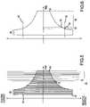
- FIG. 6is diagram of an envelope of the non-arcing portion of the current waveform shown in FIG. 5 , showing various points during the tissue sealing treatment cycle.
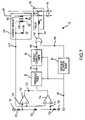
- FIG. 7is a circuit diagram of electronic components of a controller of the tissue sealing apparatus shown in FIG. 1 .
- FIGS. 8 and 9are waveform diagrams having a common time reference which illustrate certain signals present in the controller shown in FIG. 7 .
- FIGS. 10 and 11are waveform diagrams having a common time reference which illustrate certain signals present in the controller shown in FIG. 7 .
- FIGS. 12 , 13 and 14are waveform diagrams having the same common time reference as that of FIGS. 8 and 9 , which illustrate certain signals present in the controller shown in FIG. 7 .
- FIG. 15is a flowchart illustrating aspects of a process flow executed by the tissue sealing apparatus in FIG. 1 when performing the tissue sealing treatment cycle, and also illustrating method aspects of the present invention.
- FIGS. 16 , 17 and 18are graphs of a range of impedances measured relative to certain current values shown in FIG. 6 , during the execution of the tissue sealing treatment cycle.
- a coaptive biological tissue sealing apparatus 30is shown in FIG. 1 .
- the coaptive tissue sealing apparatus 30is used to permanently close a lumen, duct, passageway or chamber formed in and surrounded by the biological tissue.
- the biological tissueis exemplified in FIG. 1 (and FIGS. 2-4 ) by a biological vessel 32 , such as an artery or vein.
- Other examples of biological tissue which may be permanently sealed by use of the present inventioninclude fallopian tubes, bile ducts, tissue surrounding an aveoli or air sac in the lung, the colon or bowel, and any other structure where ligation might otherwise be performed.
- the vessel 32will be used as an example of the biological tissue which is sealed, and a lumen 34 in the vessel 32 will exemplify the lumen, duct, passageway or chamber which is to be permanently occluded by sealing the biological tissue.
- the biological tissue of the vessel 32is represented by a sidewall 36 of the vessel 32 .
- the lumen, duct, passageway or chamber in the biological tissuewill be referred to generically as an “opening” in the context of the following appended claims which define the invention, although this detailed description of the preferred embodiments may also occasionally refer to an “opening” in the same generic context.
- That portion of the biological tissue which surrounds and defines the “opening”will be referred to as a “sidewall” in the context of the following appended claims which define the invention, and throughout this detailed description of the preferred embodiments since the vessel 32 is defined by its sidewall 36 . Therefore, in accordance with this naming convention, the sidewall 36 of the vessel 32 as used in the following detailed description is one example of “sidewall” of the biological tissue which is sealed, and the lumen 34 of the vessel 32 is one example of an “opening” which may be permanently occluded or closed by sealing the apposite portion of the “sidewall” of the biological tissue which initially defined and surrounded the “opening”.
- a conventional hand piece 38 of the apparatus 30is manipulated by a surgeon or medical personnel to grip the vessel 32 or other tissue between jaws 40 of the handpiece 38 and compress opposite portions of the sidewall 36 of the vessel 32 in apposition with one another to occlude a lumen 34 through the vessel 32 and to force the apposed sidewall portions 36 into a diminished thickness compared to their natural thickness.
- a conventional electrosurgical generator (ESG) 42is activated to deliver electrosurgical energy to the compressed apposite portions of the vessel sidewall 36 .
- the electrosurgical energy delivered by the electrosurgical generator 42 in accordance with the present inventionis typically bipolar radio frequency (RF) electrosurgical energy.
- the energyis delivered from the electrosurgical generator 42 in response to closing or otherwise activating a control switch 44 , such as a conventional ESG foot switch.
- the electrosurgical energyis conducted through a controller 46 and through a cable 48 to the jaws 40 of the handpiece 38 .
- the jaws 40include electrodes 50 for conducting the electrosurgical energy through the compressed apposite portions of the sidewall 36 of the vessel 32 .
- the electrical energyis conducted through the compressed apposite portions of the vessel sidewall 36 and heats those sidewall portions.
- the compressed apposite sidewall portionsare permanently fused or sealed together as a result of the mechanical compression force and the heat created by electrical energy conducted through the sidewall portions.
- the fusion of the apposite sidewall portionspermanently occludes the lumen 34 through the vessel 32 , thereby preventing fluid which is normally conducted through the lumen 34 from leaking through the occlusion and from the vessel 32 .
- Reliably and permanently occluding the vessel 32is very important in surgery.
- the permanent occlusionprevents blood loss during the surgical procedure and after the procedure has been completed and any incision in the patient has been closed.
- sealing the aveolipermits the lung to function as an air-tight enclosure which is necessary for effective respiration.
- the integrity of the occlusionis sufficient to withstand the normal range of pressures of the fluid within the biological tissue.
- that normal range of pressureswill be the systolic and diastolic blood pressure.
- the seal created by the present inventionwill have sufficient integrity to withstand ruptures from a range of fluid pressures which is considerably greater than the normal range of pressures experienced by the biological tissue which defines the lumen or opening within the vessel.
- the technique for fusing or sealing biological tissueis relatively well-known.
- the application of the heat energy combined with sufficient compression of the apposed sidewall portions of the vessel 32first loosens or denatures the natural intertwined or cross-linked fibers within the tissue, principally collagen and elastin fibers. Loosening the natural physical structure of these fibers makes them more malleable or flexible and allows them to fuse and reform into another different intertwined physical structure with other fibers while cooling.
- the compression of the tissue while the fibers are loosened and flexibleallows the fibers of the apposed sidewall portions to intertwine with one another, thereby permanently creating a fused intertwined physical structure of those fibers, and this fused intertwined physical structure permanently seals the apposed sidewall portions together into the permanent occlusion of the lumen 34 or opening.
- the type of handpiece 38 shown in FIG. 1includes two arms 52 which are pivotally connected together at a middle pivot point 54 to locate the jaws 40 on the distal ends of the arms 52 .
- Finger enclosures 56are formed on the opposite end of the arms 52 from the jaws 40 . Squeezing finger enclosures 56 toward one another pivots the arms 52 about the pivot point 54 and moves the jaws 40 toward one another from an open position surrounding the vessel 32 , shown in FIG. 2 . Further movement of the finger enclosures 56 toward one another causes the jaws 40 to compress the sidewall 36 and close the lumen 34 , as shown in FIG. 3 . In the state shown in FIG.
- the opposite portions of the sidewall 36have contacted one another in apposition and completely close the lumen 34 .
- the relative thickness of the apposite portions of the sidewall 36has compressed somewhat to the limit of the force applied from the jaws 40 against the unheated sidewalls 36 of the vessel 32 .
- the resistance of compressing the apposite portions of the sidewall 36causes the arms 52 to deflect toward one another along their longitudinal extension.
- Tabs 58extend toward one another near the proximal end of the arms 52 on the opposite side of the arms 52 from the finger enclosures 56 ( FIG. 1 ).
- the tabs 58include teeth 60 which extend from the tabs 48 in a mutually facing relationship.
- the teeth 60selectively engage one another and disengage from one another when the proximal ends of the arms 32 move close to one another as a result of finger pressure applied by squeezing the finger enclosures 56 .
- the teeth 60engage one another in a ratchet-like or detent-like manner to maintain the compressive force on the apposite portions of the sidewall 36 .
- the tissue structure of the sidewall 36collapses to reduce the resistance created by compression of the tissue between the jaws 40 .
- the jaws 40move slightly closer to one another as a result of the tissue collapse. Some of the resistance force caused by the initial compression of the tissue between the jaws 40 is diminished, causing the amount of deflection of the arms 52 to be slightly reduced. However, the amount of resistance resulting from tissue collapse is not so great as to completely eliminate any resistance from the heated and compressed apposite portions of the sidewall 36 , and therefore the resistance still maintains the teeth 60 of the tabs 58 of the handpiece engaged together.
- the continued engagementensures that pressure is continuously applied to the apposite compressed portions of the sidewall 36 until the handpiece 38 is removed from the sealed vessel 32 .
- the teeth 60 of the tabs 58are disengaged from one another by deflecting the arms 52 to separate the tabs 58 from one another, thereby releasing the vessel 32 from the jaws 40 .
- the electrodes 50are positioned on the jaws 40 and are electrically insulated from the jaws to conduct the electrical energy between one another and through the apposite compressed portions of the sidewall 36 .
- the electrodes 50are part of a disposable assembly which is connected to at least one of the arms 52 and to both jaws 40 .
- the electrodes 50conduct the bipolar electrical energy as a result of connecting the electrode 50 on one jaw 40 to one pole of the bipolar electrical energy and connecting the electrode 50 on the other jaw 40 to conduct the other pole of the bipolar electrical energy.
- the two poles of bipolar electrical energyare conducted through separate conductors within the cable 48 and through an enclosure 62 , which is attached to one of the arms 52 and which is part of the disposable assembly, to the electrodes 50 on the jaws 40 .
- the electrodes 50are connected to electrically opposite poles of the output energy from the electrosurgical generator 42 , it is important that the electrodes 50 are not allowed to contact one another. Such contact would result in short-circuiting the bipolar electrosurgical energy delivered from the electrosurgical generator 42 and might damage the generator 42 .
- the mechanical structure of the handpiece 38prevents the jaws 40 from completely closing in contact with one another as the tissue is heated as shown in FIG. 4 . Instead, the jaws 40 stop moving toward one another at a position which creates a relatively narrow and uniform width gap of about 0.1 mm between the jaws 40 . Fixing the gap between the jaws 40 in this manner also prevents the jaws 40 from mechanically severing the vessel 32 as a result of energy or pressure applied during tissue fusion.
- the parallel facing relationship of the jaws 40also creates a relatively uniform thickness of apposite compressed portions of the sidewall 36 between the electrodes 50 .
- the uniform thickness of the apposite compressed sidewall portionsprovides a relatively uniform and equally distributed electrical load for conducting the electrical energy uniformly between electrodes 40 and through the compressed apposite sidewall portions of the vessel 32 .
- the relatively uniform loaddistributes the electrical energy uniformly across the lateral dimension of the apposite compressed sidewall portions, thereby assuring that the amount of heating is approximately uniform in the lateral sense across the compressed apposite sidewall portions.
- Uniform distribution of the electrical energyis important to prevent some locations of the compressed apposite sidewall portions from becoming too hot and permanently influencing adversely the ability of the tissue fibers to fuse and intertwine while leaving other locations of the compressed apposite sidewall portions without enough heat to adequately fuse and intertwine the fibers in those locations.
- the uniform energy distributionassures that all locations along the lateral width of the compressed apposite sidewall portions are heated approximately to the same extent at approximately the same time to achieve effective tissue fusion.
- Another factor which can influence the strength and integrity of the tissue fusionis the amount and characteristics of the energy applied to heat and otherwise influence the fusing and intertwining characteristics of the fibers in the tissue.
- the application of the energy for heating the tissueis particularly important because it is more difficult to control compared to the compression of the tissue. Compression of the tissue, as described in conjunction with FIGS. 3 and 4 , is relatively consistently obtained due to the mechanical nature of the handpiece and its ability to compress the apposite sidewall portions to approximately the same extent. If insufficient heat is applied, the fibers will not loosen sufficiently to reform in a fused and intertwined matter. If excessive heat is applied, the fibers are adversely affected to the point that they do not fuse and intertwine in the best effective manner.
- RF electrosurgical energyWhen RF electrosurgical energy is used for tissue fusion, applying the additional energy necessary to achieve adequate tissue fusion will generally result in the generation of arcs of the RF energy.
- the arcshave the tendency to penetrate into the tissue and may weaken the sidewall adjacent to the fused apposite sidewall portions, thereby diminishing the strength of the sidewall and creating the possibility of fluid leaks at the sealed location or at locations adjacent to the sealed location. It is therefore important to control the amount of energy applied to the tissue to achieve the best seal to avoid the problems associated with inadequate and excessive energy and heat application.
- the controller 46controls the amount of energy applied to the tissue to obtain the best seal from fusing and intertwining the tissue fibers.
- the functionality of the controller 46is based on the recent discovery that the energy application for tissue sealing is controlled very advantageously in relation to a precursor fusion condition involving the peak RF current delivered to the tissue not exceeding a predetermined threshold for a predetermined threshold time, as is described in greater detail below. After the occurrence of this precursor fusion condition, it is necessary to deliver additional energy to the tissue to obtain an effective seal or fusion of the compressed apposite sidewall portions of the tissue. Terminating the delivery of electrosurgical energy at the moment when the precursor fusion condition exists has been shown experimentally not to result in an effective seal.
- the additional energy added after the occurrence of the precursor fusion conditionmust be sufficient to drive off a substantial portion of the intracellular fluid within the cells of the tissue.
- Removing the intercellular fluidis believed to create the beneficial effect of locating tissue fibers within sufficiently close physical proximity to fuse and intertwine without the intracellular fluid interfering with the fusion and intertwining.
- Eliminating a substantial portion of the intracellular fluidis accomplished by delivering enough additional energy to vaporize the intracellular fluid.
- the intracellular fluidis predominantly water. Consequently, the temperature of the intercellular fluid must be raised to or above 1000 Celsius in order to vaporize that intercellular fluid.
- the controller 46monitors an RF current 64 ( FIG. 5 ) delivered from the electrosurgical generator 42 to determine the existence of the precursor fusion condition. The controller then permits the continued delivery of the additional electrical energy for a predetermined time sufficient to achieve effective tissue fusion before terminating delivery of electrical energy to the tissue. When the delivery of electrosurgical energy is terminated, the heated and compressed apposite sidewall portions are allowed to cool, to complete the fusion of the tissue. Thereafter the handpiece 38 is removed from the vessel 32 . If desired, the vessel 32 can then be severed at a location adjacent to the fused apposed sidewall portions. In some circumstances, two seals at fusion locations which are longitudinally displaced along the vessel 32 may be created, so that the vessel can be severed between those seals or fusion locations.
- the condition of the RF current 64 which is monitored by the controller 46is understood by reference to FIG. 5 , which shows the RF current 64 delivered from the electrosurgical generator 42 and conducted through the compressed apposite portions of the sidewall 36 ( FIGS. 3 and 4 ) during a single treatment cycle 66 in which tissue fusion or sealing is achieved.
- the treatment cycle 66begins with an initial delivery of the RF current 64 from the electrosurgical generator 42 at cycle starting point 67 during an initial heating phase 68 of the treatment cycle 66 .
- the peak RF current 64 delivered to the compressed apposite sidewall portionsis relatively constant.
- the peak value and amount of the RF current 64 delivered during the initial heating phase 68is dependent primarily on the capability of the electrosurgical generator to deliver power into relatively low resistance or impedance tissue.
- the RF current 64begins to heat the compressed apposite portions of the sidewall 36 of the vessel 32 .
- the temperature of the compressed apposite sidewall portionsincreases and is generally related to the amount of energy delivered to the tissue during the initial heating phase 68 , and generally increases substantially linearly during the initial heating phase 68 .
- the envelope of the non-arcing RF current 64decreases during a current reduction phase 76 of the treatment cycle 66 , primarily as a result of desiccation of the tissue resulting from vaporization of the intracellular fluid. As the desiccation continues, the impedance of the tissue increases to a point where arcing may commence, at point 78 .
- the arcsare illustrated by the relatively high-amplitude and short time duration spikes in the RF current 64 , in both the positive and negative directions.
- the controller 46terminates the delivery of electrical energy to the tissue.
- the precursor fusion conditionis typically determined during the current reduction phase 76 of the treatment cycle 66 . However, in some circumstances, the precursor fusion condition may be determined during the initial heating phase 68 .
- a detector of the controller 46establishes a threshold value 82 , which as shown in FIG. 6 is somewhat lower than the peak RF current occurring during the initial heating phase 68 . After the peak RF current 64 initially falls below the threshold value 82 at point 84 , the controller 46 thereafter determines that the peak RF current 64 remains below the threshold value 82 for a predetermined threshold time 83 commencing after point 84 .
- the threshold time 83ends at point 86 .
- the relative time between points 84 and 86defines the threshold time 83 during which the peak RF current 64 must remain below the threshold value 82 .
- the duration of the threshold time 83 during which the peak RF current 64 must remain below the threshold value 82happens so that the point 86 occurs before the arcing commences at point 78 ( FIG. 5 ). Accordingly, the arcing will not interfere with the determination of the precursor fusion condition established by the peak RF current value not exceeding the threshold value 82 during the threshold time 83 between points 84 and 86 .
- the peak RF current 64exceeds the threshold value 82 at any time during the threshold time 83 , the measurement of the precursor fusion condition is commenced again beginning immediately after the peak RF current exceeded the threshold value. On the other hand, if the peak RF current 64 exceeds the threshold value 82 after of the threshold time 83 has been established, that condition is ignored. However, the possibility of the peak RF current exceeding the threshold value after the threshold time has been established is relatively remote.
- an energy completion time or delivery window 88is established by the controller 46 .
- the energy completion time 88commences at point 86 and extends to point 80 , where the treatment cycle 66 ends as a result of the controller 46 terminating the delivery of energy from electrosurgical generator 42 to the tissue.
- the additional amount of energyis delivered from the electrosurgical generator to the tissue necessary to assure effective tissue fusion.
- controller 46The functional components of the controller 46 which achieve the RF current monitoring and controlling functions are shown and described in conjunction with FIG. 7 taken in conjunction with FIGS. 5 , 6 and 8 - 14 which illustrate waveforms of various signals applicable to the components of the controller shown in FIG. 7 .
- the treatment cycle 66begins when the control switch 44 is closed or activated ( FIG. 1 ). Activation of the control switch 44 delivers an activation signal 90 ( FIG. 8 ) to the electrosurgical generator 42 and the controller 46 ( FIG. 1 ).
- the activation signal 90causes the electrosurgical generator 42 to begin delivering output electrosurgical energy of which the RF current 64 is a constituent part.
- the activation signal 90enables a threshold timer 92 , an energy completion timer 94 , and a maximum treatment duration timer 96 .
- the threshold timer 92 and the maximum treatment duration timer 96commence counting time values which have been established for those timers 92 and 96 in response to the activation signal 90 .
- a relay 98includes switch contacts 99 which are normally closed. The normally closed switch contacts 99 conduct the electrosurgical RF current 64 from the electrosurgical generator 42 through the controller 46 to the cable 48 and the handpiece 38 ( FIG. 1 ).
- the characteristics of the RF current 64 conducted through the controller 64are sensed by a current sensor 100 .
- the current sensor 100includes a current sense transformer 102 having a primary winding 104 through which the RF current 64 flows.
- a secondary winding 106 of the current sense transformer 102develops a secondary current which is directly related to the magnitude and characteristics of the RF current 64 .
- the secondary current from the secondary winding 106is conducted through a resistor 108 , and a voltage is developed across the resistor 108 which is directly related to the characteristics of the RF current 64 delivered by the electrosurgical generator 42 .
- the voltage developed across the resistor 108is a current sense signal 110 .
- Comparators 112 and 114receive the sense signal 110 and two threshold comparison signals 116 and 118 .
- the threshold comparison signals 116 and 118are developed by a voltage divider formed by resistors 120 , 122 and 124 which are connected in series between a positive power supply 126 and a negative power supply 128 .
- the magnitudes of the threshold comparison signals 116 and 118correspond to the positive and negative values of the threshold value 82 ( FIG. 6 ).
- Positive and negative threshold comparison signals 116 and 118are required to assure that the peak RF current 64 does not exceed the threshold value 82 ( FIG. 6 ) in either the positive or the negative sense, since the RF current 64 alternates in positive and negative half cycles.
- the values of the resistors 120 , 122 and 124establish the level of the threshold comparison signals 116 and 118 as equal to one another but of opposite polarity with respect to reference potential.
- the threshold comparison signal 116is applied to the inverting input terminal of the comparator 112 .
- the threshold comparison signal 118is applied to the noninverting terminal of the comparator 114 .
- the sense signal 110is applied to the noninverting input terminal of the comparator 112 and to the inverting input terminal of the comparator 114 .
- the comparators 112 and 114determine if the peak amplitude of the sense signal 110 is greater or less than the threshold comparison signals 116 and 118 . As understood from FIGS.
- one of the comparators 112 and 114asserts a reset signal 130 at a logic high level.
- the comparators 112 and 114assert the reset signal 130 at a logic low level.
- the applicable one of the comparators 112 or 114will assert the reset signal 130 at the logic high level. In this manner, should either of the threshold comparison signals 116 or 118 be exceeded in either the positive or the negative sense by the positive and negative half cycles of the sense signal 110 , a high-level reset signal 130 will be asserted to the threshold timer 92 .
- the threshold timer 92is enabled to commence counting in response to the assertion of the activation signal 90 . Because the RF current 64 is relatively high during the initial heating phase 68 compared to the threshold value 82 ( FIG. 6 ), the peak values of the sense signal 110 will exceed the positive and negative threshold comparison signals 116 and 118 almost immediately after the RF current 64 is initially delivered from the electrosurgical generator 42 . The comparators 112 and 114 assert the reset signal 130 as the positive and negative half cycles of the sense signal 110 exceed the threshold comparison signals 116 and 118 in a positive and negative sense. Consequently, the threshold timer 92 is repeatedly reset by the assertion of the reset signal 130 to prevent it from counting down to the full duration of the threshold time 83 ( FIG. 12 ).
- the threshold timer 92is able to assert the precursor trigger signal 134 ( FIG. 13 ).
- the assertion of the precursor trigger signal 134indicates that the threshold timer 92 has successfully counted down to zero.
- the successful count down to zerobegins after the last time that the reset signal 130 changes from a logic high level to a logic low level, as shown at 131 in FIGS. 12 and 13 . While the threshold timer 92 is counting but has not reached the final count of the threshold time 83 , the precursor trigger signal 134 is asserted at a logic low level.
- the transition between the logic low level and the logic high level of the precursor trigger signal 134occurs at 138 shown in FIG. 13 .
- the threshold timer 92counts down to zero, thereby indicating the expiration of the threshold time 83
- the assertion of the logic high precursor trigger signal 134indicates that the RF current 44 has remained below the threshold value 82 ( FIG. 6 ) for the threshold time 83 .
- the energy completion timer 94responds to the assertion of a high-level precursor trigger signal 134 by commencing to count the energy completion time 88 as indicated at 138 in FIG. 14 .
- the energy completion timer 94changes a termination signal 140 from a logic low level to a logic high level as shown at 141 in FIG. 14 .
- An OR gate 142is connected to receive the termination signal 140 from the energy completion timer 94 .
- the OR gate 142delivers a relay control signal 144 at 141 to the relay 98 as shown in FIG. 9 .
- the relay 98which has switch contacts 99 that are normally closed, responds to the relay control signal 144 by opening the switch contacts 99 and thereby terminating the flow of the RF current 64 from the generator 42 to the handpiece 38 . Opening the switch contacts 99 discontinues the delivery of electrical energy to the vessel 32 at the energy delivery termination point 80 ( FIG. 6 ).
- the maximum duration timer 96assures that the electrical energy from the generator 42 is not applied to the tissue of the vessel 32 for an excessively long amount of time.
- the maximum duration timer 96receives the activation signal 90 from the control switch 44 ( FIG. 1 ) at the same time that the electrosurgical generator 42 begins delivering electrosurgical energy to the handpiece 38 .
- the activation signal 90enables the maximum duration timer 96 to start counting down a maximum duration time for the entire treatment cycle 66 .
- the maximum duration timer 96is preferably set with a maximum duration time of approximately 18 seconds. If the maximum duration timer 96 counts all the way down to zero after 18 seconds, the timer 96 asserts a maximum duration signal 150 to the OR gate 142 .
- the OR gate 142responds by asserting the relay control signal 144 to the relay 98 which causes the switch contacts 99 to open and terminate the delivery of electrical power to the handpiece 38 .
- the maximum duration timer 96is set to a time that is longer than the duration of a normal treatment cycle 66 ( FIG. 5 ) is expected to last under normal conditions. If the maximum duration timer 96 terminates the power delivery, then an unexpected problem or condition exists. That unexpected problem may be safety related and terminating the delivery of further electrosurgical energy under these conditions may be warranted, at least for the particular treatment cycle 66 which has then been attempted.
- the events involved in operating and using the coaptive sealing apparatus 30 during a treatment cycle 66 , and the events involved in performing the method of coaptive tissue sealing,are summarized in the sequence 200 shown in FIG. 15 .
- the sequence 200begins at 202 . Thereafter, the vessel 32 is compressed at 204 ( FIG. 4 ), by use of the handpiece 38 ( FIG. 1 ). Next, it is determined at 206 whether the control switch 34 ( FIG. 1 ) has been activated. If the determination at 206 is negative, then a waiting loop is executed until the control switch 34 is activated. Activation of the control switch is recognized by a positive determination at 206 . At this point, the sequence 200 diverges into two simultaneously-executed sub-series of events 208 and 210 .
- the sub-series of events 208involve limiting the maximum time duration of the treatment cycle 66
- the sub-series of events 210involve the normal execution of a treatment cycle 66 for fusing or sealing tissue.
- the sub-series of events 208commences at 212 with starting the maximum duration timer 96 ( FIG. 7 ) to begin its countdown.
- a waiting loopis executed as indicated by the negative determination at 214 until the maximum time duration established by the timer 96 has been reached or counted down to zero. If the maximum time duration is reached, as indicated by an affirmative determination at 214 , the delivery of electrical energy is terminated at 216 , as a result of opening the switch contacts 99 of the relay 98 ( FIG. 7 ).
- a normal treatment cycle 66is typically completed well before the maximum duration timer 96 terminates the delivery of electrical energy from the generator to the handpiece.
- the sub-series of events 208come into play only under conditions when the normal functionality of the treatment cycle 66 fails for some unexpected reason. Normally speaking the normal treatment cycle 66 represented by the sub-series of events 210 will be executed as intended, and consequently, the sub-series of events 208 will not be completed as just described.
- the sub-series of events 210relate to the execution of a normal treatment cycle 66 .
- the execution of a normal treatment cyclecommences with the delivery of electrosurgical energy at 218 . After the energy delivery begins, a determination is made at 220 . The determination made at 220 involves detecting whether the precursor fusion described above has occurred. If the precursor fusion condition has not been detected, the determination at 220 is negative and a waiting loop is executed until the precursor fusion condition has been detected by a positive determination at 220 .
- a positive determination at 220triggers the energy completion timer 94 ( FIG. 7 ) at 222 to begin counting the energy completion time 88 ( FIGS. 5 , 6 and 14 ).
- the determination at 224is affirmative, indicating that the electrosurgical generator 42 has applied an adequate amount of electrical energy to the tissue for an effective seal, the sequence advances to 226 , where the delivery of the electrosurgical energy is terminated. Under these circumstances, the switch contacts 99 of the relay 98 ( FIG. 7 ) are opened, and the delivery of energy from the electrosurgical generator 42 is terminated, despite the fact that the control switch 44 ( FIG. 1 ) may remain activated or closed.
- the opposed portions of the sidewall 36 of the tissue( FIGS. 3 and 4 ) are allowed to cool at 228 while the compressive force or pressure remains applied by the jaws 40 ( FIG. 4 ) as the tissue cools. Cooling while the tissue is compressed allows the tissue fibers to intertwine and fuse together in a manner which resists separation.
- the compression force or pressure on the sealed apposite portions of the sidewall 36is released at 230 by opening the jaws 40 ( FIG. 2 ) after having disengaged the teeth 60 of the tabs 58 ( FIG. 1 ). Thereafter, the sequence 200 returns to 202 to await the beginning of another treatment cycle 66 ( FIG. 5 ).
- the present inventionhas been implemented by using a ConMed System 5000 electrosurgical generator as the electrosurgical generator 42 and both a handheld version and a 5 mm laparoscopic version of a ValleyLab Ligasure handpiece as the handpiece 38 .
- the ConMed System 5000 electrosurgical generatorwas operated in a fluid bipolar mode.
- the advantage of using the fluid bipolar modeis that it has the capability of delivering a relatively high amount of power into a relatively low impedance tissue. This characteristic is advantageously used to deliver enough electrical energy into the compressed apposite portions of the sidewall 36 tissue to rapidly heat the sidewall portions during the initial heating phase 68 ( FIG. 5 ).
- the fluid bipolar modewas originally intended to be used in arthroscopic surgery where the surgical site is totally immersed in water or saline.
- the boosted power capacity and lower internal source impedance in the fluid bipolar modecreates an added capability to quickly deliver energy, which is useful in the present invention to quickly heat the compressed apposite sidewall portions of the tissue.
- the ConMed System 5000 electrosurgical generatorwas set to deliver 90 watts of electrosurgical energy when used with the handheld Valleylab Ligasure handpiece.
- the ConMed System 5000 electrosurgical generatorwas set to deliver 70 watts of electrosurgical energy when used with the laparoscopic Valleylab Ligasure handpiece.
- the threshold value 82was established at 1.0 amps (and the threshold level signals 116 and 118 ( FIG. 7 ) were set correspondingly) and the threshold time 83 was established at 150 milliseconds.
- the duration of the energy completion time 88was established at 980 milliseconds. These values were equally useful for sealing arteries and veins of a relatively small diameter up to approximately 12 mm in diameter.
- the threshold value, the threshold time and the energy completion timeproved satisfactory for use with both versions of the Valleylab Ligasure handpiece.
- the experimental seal time for arteries and veinswas about 3 to 5 seconds.
- the published times required for performing a single seal of a vessel using a popular prior art tissue sealing deviceis about the same, thereby demonstrating superiority or comparability of the present invention in regard to the time required to accomplish single tissue seals.
- the widely accepted practice of using the popular prior art tissue sealing deviceis to perform four separate seals, with two of the seals overlapped and with each pair of overlapped seals spaced longitudinally from one another along the length of the vessel, makes total sealing times in the neighborhood of approximately 20 seconds commonplace. Tests performed with the embodiment of the invention described above have demonstrated that a single seal is just as effective as the four repetitive seals performed with the popular prior art tissue sealing device.
- Mean burst pressures of a single seal on a vessel accomplished by use of the above described embodiment of the present inventionare equal or somewhat greater than the mean burst pressures of a multiple seal on a comparable vessel accomplished by use of the popular prior art tissue sealing device.
- the values for the threshold RF current, the threshold time and the energy completion timewere established relative to the implemented form of the invention described above. These values may need to be adjusted for other types of electrosurgical generators depending on, among other things, the output energy delivery characteristics of the other generators, the source impedances of the other generators, the real or apparent power regulation characteristics of the other generators, the impedance of the handpieces used, and the type of tissue which is sealed. Note however, that no changes were required to the above-described embodiment of the invention when sealing a relatively wide range of different sized arteries and veins.
- the general approach of timing the termination point of the electrical energy delivered to the compressed apposite portions of the sidewall 36 based on sensing the peak RF current so as to not exceed the threshold value for the threshold time, and thereafter measuring an energy completion time relative to this precursor fusion conditionis expected to perform satisfactorily with any electrosurgical generator which has the capability of delivering relatively significant amounts of power in a relatively short time into relatively low impedances, such as those represented by the compressed apposite portions of the sidewall 36 of the tissue to be sealed, in combination with popular tissue sealing handpieces, when used on the typical types of tissues which are normally sealed during typical medical procedures.
- FIG. 16shows the range of impedance which have been observed to occur relative to different values of RF current 64 when the precursor fusion condition is achieved, i.e. at point 86 ( FIG. 6 ). Different values of RF current 64 have been observed because of the different types of tissue tested.
- the range of impedance at each of these precursor conditionsindicates that a single impedance value does not correlate to the precursor condition, and therefore a single impedance value would not be a suitable replacement for determining the precursor fusion conditions for controlling the termination of electrical energy delivery when completing the tissue sealing treatment cycle 66 .
- FIG. 17illustrates that a wide range of impedances also exist at the start of determining the precursor fusion condition, i.e. at point 84 ( FIG. 6 ).
- FIG. 18illustrates that a variety of different impedances also exist for each of the current values that were observed during tests at the energy delivery termination point 80 ( FIG. 5 ). Accordingly, the impedance ranges shown in FIGS. 16-18 demonstrate that the precursor fusion condition determination made in accordance with the present invention does not correlate to the use of impedance values as are typically employed in prior art tissue fusion devices.
- the electrosurgical generator 42delivers the electrical energy in accordance with its normal functionality to obtain effective tissue sealing or fusion.
- the controller 46senses the current to determine when the desired precursor fusion condition occurs. Thereafter only the additional energy is applied which is necessary to ensure an effective seal without weakening the tissue due to excessive energy application and without compromising the integrity of the seal by not delivering adequate energy.
- the functionality of the controller 46greatly simplifies the tissue sealing process, since only straightforward threshold comparisons and timing determinations are used in relation to sensing the peak RF current 64 . Many other advantages and improvements will be apparent upon gaining a full appreciation for the present invention.
Landscapes
- Health & Medical Sciences (AREA)
- Surgery (AREA)
- Engineering & Computer Science (AREA)
- Life Sciences & Earth Sciences (AREA)
- Biomedical Technology (AREA)
- Otolaryngology (AREA)
- Nuclear Medicine, Radiotherapy & Molecular Imaging (AREA)
- Plasma & Fusion (AREA)
- Physics & Mathematics (AREA)
- Heart & Thoracic Surgery (AREA)
- Medical Informatics (AREA)
- Molecular Biology (AREA)
- Animal Behavior & Ethology (AREA)
- General Health & Medical Sciences (AREA)
- Public Health (AREA)
- Veterinary Medicine (AREA)
- Surgical Instruments (AREA)
Abstract
Description
Claims (26)
Priority Applications (1)
| Application Number | Priority Date | Filing Date | Title |
|---|---|---|---|
| US11/228,891US7678105B2 (en) | 2005-09-16 | 2005-09-16 | Method and apparatus for precursively controlling energy during coaptive tissue fusion |
Applications Claiming Priority (1)
| Application Number | Priority Date | Filing Date | Title |
|---|---|---|---|
| US11/228,891US7678105B2 (en) | 2005-09-16 | 2005-09-16 | Method and apparatus for precursively controlling energy during coaptive tissue fusion |
Publications (2)
| Publication Number | Publication Date |
|---|---|
| US20070066969A1 US20070066969A1 (en) | 2007-03-22 |
| US7678105B2true US7678105B2 (en) | 2010-03-16 |
Family
ID=37885208
Family Applications (1)
| Application Number | Title | Priority Date | Filing Date |
|---|---|---|---|
| US11/228,891Active2027-11-02US7678105B2 (en) | 2005-09-16 | 2005-09-16 | Method and apparatus for precursively controlling energy during coaptive tissue fusion |
Country Status (1)
| Country | Link |
|---|---|
| US (1) | US7678105B2 (en) |
Cited By (122)
| Publication number | Priority date | Publication date | Assignee | Title |
|---|---|---|---|---|
| US20080147057A1 (en)* | 2005-01-26 | 2008-06-19 | Florian Eisele | High-Frequency Surgical Device |
| US20080228181A1 (en)* | 2007-02-25 | 2008-09-18 | Baylis Medical Company | Electrosurgical method |
| US20110071516A1 (en)* | 2009-09-24 | 2011-03-24 | Tyco Healthcare Group Lp | System and Method for Controlling Electrosurgical Output |
| US8231616B2 (en) | 2006-09-28 | 2012-07-31 | Covidien Ag | Transformer for RF voltage sensing |
| US8241278B2 (en) | 2005-12-12 | 2012-08-14 | Covidien Ag | Laparoscopic apparatus for performing electrosurgical procedures |
| US8267928B2 (en) | 2006-01-24 | 2012-09-18 | Covidien Ag | System and method for closed loop monitoring of monopolar electrosurgical apparatus |
| US8267929B2 (en) | 2003-05-01 | 2012-09-18 | Covidien Ag | Method and system for programming and controlling an electrosurgical generator system |
| US8486061B2 (en) | 2009-01-12 | 2013-07-16 | Covidien Lp | Imaginary impedance process monitoring and intelligent shut-off |
| US8485993B2 (en) | 2003-10-30 | 2013-07-16 | Covidien Ag | Switched resonant ultrasonic power amplifier system |
| US8523855B2 (en) | 2002-12-10 | 2013-09-03 | Covidien Ag | Circuit for controlling arc energy from an electrosurgical generator |
| US8636730B2 (en) | 2010-07-12 | 2014-01-28 | Covidien Lp | Polarity control of electrosurgical generator |
| US8647340B2 (en) | 2003-10-23 | 2014-02-11 | Covidien Ag | Thermocouple measurement system |
| US9044238B2 (en) | 2012-04-10 | 2015-06-02 | Covidien Lp | Electrosurgical monopolar apparatus with arc energy vascular coagulation control |
| US9078655B2 (en) | 2009-04-17 | 2015-07-14 | Domain Surgical, Inc. | Heated balloon catheter |
| US9107666B2 (en) | 2009-04-17 | 2015-08-18 | Domain Surgical, Inc. | Thermal resecting loop |
| US9113900B2 (en) | 1998-10-23 | 2015-08-25 | Covidien Ag | Method and system for controlling output of RF medical generator |
| US9131977B2 (en) | 2009-04-17 | 2015-09-15 | Domain Surgical, Inc. | Layered ferromagnetic coated conductor thermal surgical tool |
| US9220557B2 (en) | 2009-04-17 | 2015-12-29 | Domain Surgical, Inc. | Thermal surgical tool |
| US9265556B2 (en) | 2009-04-17 | 2016-02-23 | Domain Surgical, Inc. | Thermally adjustable surgical tool, balloon catheters and sculpting of biologic materials |
| US9265560B2 (en) | 2011-02-25 | 2016-02-23 | Covidien Lp | System and method for detecting and suppressing arc formation during an electrosurgical procedure |
| US9526558B2 (en) | 2011-09-13 | 2016-12-27 | Domain Surgical, Inc. | Sealing and/or cutting instrument |
| US9549774B2 (en) | 2009-04-17 | 2017-01-24 | Domain Surgical, Inc. | System and method of controlling power delivery to a surgical instrument |
| US9636165B2 (en) | 2013-07-29 | 2017-05-02 | Covidien Lp | Systems and methods for measuring tissue impedance through an electrosurgical cable |
| US20170258515A1 (en)* | 2015-09-25 | 2017-09-14 | Olympus Corporation | Power supply apparatus, operating system including the power supply apparatus, and method of operating the power supply apparatus |
| US9872719B2 (en) | 2013-07-24 | 2018-01-23 | Covidien Lp | Systems and methods for generating electrosurgical energy using a multistage power converter |
| US10105174B2 (en) | 2012-04-09 | 2018-10-23 | Covidien Lp | Method for employing single fault safe redundant signals |
| US10285724B2 (en) | 2014-07-31 | 2019-05-14 | Ethicon Llc | Actuation mechanisms and load adjustment assemblies for surgical instruments |
| US10299821B2 (en) | 2016-01-15 | 2019-05-28 | Ethicon Llc | Modular battery powered handheld surgical instrument with motor control limit profile |
| US10335183B2 (en) | 2012-06-29 | 2019-07-02 | Ethicon Llc | Feedback devices for surgical control systems |
| US10335182B2 (en) | 2012-06-29 | 2019-07-02 | Ethicon Llc | Surgical instruments with articulating shafts |
| US10342602B2 (en) | 2015-03-17 | 2019-07-09 | Ethicon Llc | Managing tissue treatment |
| US10349999B2 (en) | 2014-03-31 | 2019-07-16 | Ethicon Llc | Controlling impedance rise in electrosurgical medical devices |
| US10357306B2 (en) | 2014-05-14 | 2019-07-23 | Domain Surgical, Inc. | Planar ferromagnetic coated surgical tip and method for making |
| US10376305B2 (en) | 2016-08-05 | 2019-08-13 | Ethicon Llc | Methods and systems for advanced harmonic energy |
| US10441310B2 (en) | 2012-06-29 | 2019-10-15 | Ethicon Llc | Surgical instruments with curved section |
| US10441345B2 (en) | 2009-10-09 | 2019-10-15 | Ethicon Llc | Surgical generator for ultrasonic and electrosurgical devices |
| US10456193B2 (en) | 2016-05-03 | 2019-10-29 | Ethicon Llc | Medical device with a bilateral jaw configuration for nerve stimulation |
| US10463421B2 (en) | 2014-03-27 | 2019-11-05 | Ethicon Llc | Two stage trigger, clamp and cut bipolar vessel sealer |
| US10512499B2 (en) | 2015-06-19 | 2019-12-24 | Covidien Lp | Systems and methods for detecting opening of the jaws of a vessel sealer mid-seal |
| US10517627B2 (en) | 2012-04-09 | 2019-12-31 | Ethicon Llc | Switch arrangements for ultrasonic surgical instruments |
| US10524854B2 (en) | 2010-07-23 | 2020-01-07 | Ethicon Llc | Surgical instrument |
| US10524872B2 (en) | 2012-06-29 | 2020-01-07 | Ethicon Llc | Closed feedback control for electrosurgical device |
| US10543008B2 (en) | 2012-06-29 | 2020-01-28 | Ethicon Llc | Ultrasonic surgical instruments with distally positioned jaw assemblies |
| US10555769B2 (en) | 2016-02-22 | 2020-02-11 | Ethicon Llc | Flexible circuits for electrosurgical instrument |
| US10575892B2 (en) | 2015-12-31 | 2020-03-03 | Ethicon Llc | Adapter for electrical surgical instruments |
| US10595929B2 (en) | 2015-03-24 | 2020-03-24 | Ethicon Llc | Surgical instruments with firing system overload protection mechanisms |
| US10603117B2 (en) | 2017-06-28 | 2020-03-31 | Ethicon Llc | Articulation state detection mechanisms |
| US10610286B2 (en) | 2015-09-30 | 2020-04-07 | Ethicon Llc | Techniques for circuit topologies for combined generator |
| US10639092B2 (en) | 2014-12-08 | 2020-05-05 | Ethicon Llc | Electrode configurations for surgical instruments |
| US10646269B2 (en) | 2016-04-29 | 2020-05-12 | Ethicon Llc | Non-linear jaw gap for electrosurgical instruments |
| US10688321B2 (en) | 2009-07-15 | 2020-06-23 | Ethicon Llc | Ultrasonic surgical instruments |
| US10702329B2 (en) | 2016-04-29 | 2020-07-07 | Ethicon Llc | Jaw structure with distal post for electrosurgical instruments |
| US10716615B2 (en) | 2016-01-15 | 2020-07-21 | Ethicon Llc | Modular battery powered handheld surgical instrument with curved end effectors having asymmetric engagement between jaw and blade |
| US10729494B2 (en) | 2012-02-10 | 2020-08-04 | Ethicon Llc | Robotically controlled surgical instrument |
| US10751117B2 (en) | 2016-09-23 | 2020-08-25 | Ethicon Llc | Electrosurgical instrument with fluid diverter |
| US10751109B2 (en) | 2014-12-22 | 2020-08-25 | Ethicon Llc | High power battery powered RF amplifier topology |
| US10765470B2 (en) | 2015-06-30 | 2020-09-08 | Ethicon Llc | Surgical system with user adaptable techniques employing simultaneous energy modalities based on tissue parameters |
| US10779845B2 (en) | 2012-06-29 | 2020-09-22 | Ethicon Llc | Ultrasonic surgical instruments with distally positioned transducers |
| US10779876B2 (en) | 2011-10-24 | 2020-09-22 | Ethicon Llc | Battery powered surgical instrument |
| US10779879B2 (en) | 2014-03-18 | 2020-09-22 | Ethicon Llc | Detecting short circuits in electrosurgical medical devices |
| US10799284B2 (en) | 2017-03-15 | 2020-10-13 | Ethicon Llc | Electrosurgical instrument with textured jaws |
| US10835307B2 (en) | 2001-06-12 | 2020-11-17 | Ethicon Llc | Modular battery powered handheld surgical instrument containing elongated multi-layered shaft |
| US10856929B2 (en) | 2014-01-07 | 2020-12-08 | Ethicon Llc | Harvesting energy from a surgical generator |
| US10856934B2 (en) | 2016-04-29 | 2020-12-08 | Ethicon Llc | Electrosurgical instrument with electrically conductive gap setting and tissue engaging members |
| US10898256B2 (en) | 2015-06-30 | 2021-01-26 | Ethicon Llc | Surgical system with user adaptable techniques based on tissue impedance |
| US10912603B2 (en) | 2013-11-08 | 2021-02-09 | Ethicon Llc | Electrosurgical devices |
| US10912580B2 (en) | 2013-12-16 | 2021-02-09 | Ethicon Llc | Medical device |
| US10925659B2 (en) | 2013-09-13 | 2021-02-23 | Ethicon Llc | Electrosurgical (RF) medical instruments for cutting and coagulating tissue |
| US10952788B2 (en) | 2015-06-30 | 2021-03-23 | Ethicon Llc | Surgical instrument with user adaptable algorithms |
| US10959806B2 (en) | 2015-12-30 | 2021-03-30 | Ethicon Llc | Energized medical device with reusable handle |
| US10959771B2 (en) | 2015-10-16 | 2021-03-30 | Ethicon Llc | Suction and irrigation sealing grasper |
| US10987123B2 (en) | 2012-06-28 | 2021-04-27 | Ethicon Llc | Surgical instruments with articulating shafts |
| US10993763B2 (en) | 2012-06-29 | 2021-05-04 | Ethicon Llc | Lockout mechanism for use with robotic electrosurgical device |
| US11033323B2 (en) | 2017-09-29 | 2021-06-15 | Cilag Gmbh International | Systems and methods for managing fluid and suction in electrosurgical systems |
| US11033325B2 (en) | 2017-02-16 | 2021-06-15 | Cilag Gmbh International | Electrosurgical instrument with telescoping suction port and debris cleaner |
| US11051873B2 (en) | 2015-06-30 | 2021-07-06 | Cilag Gmbh International | Surgical system with user adaptable techniques employing multiple energy modalities based on tissue parameters |
| US11090104B2 (en) | 2009-10-09 | 2021-08-17 | Cilag Gmbh International | Surgical generator for ultrasonic and electrosurgical devices |
| US11090103B2 (en) | 2010-05-21 | 2021-08-17 | Cilag Gmbh International | Medical device |
| US11129670B2 (en) | 2016-01-15 | 2021-09-28 | Cilag Gmbh International | Modular battery powered handheld surgical instrument with selective application of energy based on button displacement, intensity, or local tissue characterization |
| US11129669B2 (en) | 2015-06-30 | 2021-09-28 | Cilag Gmbh International | Surgical system with user adaptable techniques based on tissue type |
| US11179173B2 (en) | 2012-10-22 | 2021-11-23 | Cilag Gmbh International | Surgical instrument |
| US11229471B2 (en) | 2016-01-15 | 2022-01-25 | Cilag Gmbh International | Modular battery powered handheld surgical instrument with selective application of energy based on tissue characterization |
| US11266430B2 (en) | 2016-11-29 | 2022-03-08 | Cilag Gmbh International | End effector control and calibration |
| US11311326B2 (en) | 2015-02-06 | 2022-04-26 | Cilag Gmbh International | Electrosurgical instrument with rotation and articulation mechanisms |
| US11324527B2 (en) | 2012-11-15 | 2022-05-10 | Cilag Gmbh International | Ultrasonic and electrosurgical devices |
| US11337747B2 (en) | 2014-04-15 | 2022-05-24 | Cilag Gmbh International | Software algorithms for electrosurgical instruments |
| US11382642B2 (en) | 2010-02-11 | 2022-07-12 | Cilag Gmbh International | Rotatable cutting implements with friction reducing material for ultrasonic surgical instruments |
| US11399855B2 (en) | 2014-03-27 | 2022-08-02 | Cilag Gmbh International | Electrosurgical devices |
| US11452525B2 (en) | 2019-12-30 | 2022-09-27 | Cilag Gmbh International | Surgical instrument comprising an adjustment system |
| US11484358B2 (en) | 2017-09-29 | 2022-11-01 | Cilag Gmbh International | Flexible electrosurgical instrument |
| US11490951B2 (en) | 2017-09-29 | 2022-11-08 | Cilag Gmbh International | Saline contact with electrodes |
| US11497546B2 (en) | 2017-03-31 | 2022-11-15 | Cilag Gmbh International | Area ratios of patterned coatings on RF electrodes to reduce sticking |
| US11589916B2 (en) | 2019-12-30 | 2023-02-28 | Cilag Gmbh International | Electrosurgical instruments with electrodes having variable energy densities |
| US11660089B2 (en) | 2019-12-30 | 2023-05-30 | Cilag Gmbh International | Surgical instrument comprising a sensing system |
| US11666375B2 (en) | 2015-10-16 | 2023-06-06 | Cilag Gmbh International | Electrode wiping surgical device |
| US11684412B2 (en) | 2019-12-30 | 2023-06-27 | Cilag Gmbh International | Surgical instrument with rotatable and articulatable surgical end effector |
| US11696776B2 (en) | 2019-12-30 | 2023-07-11 | Cilag Gmbh International | Articulatable surgical instrument |
| US11723716B2 (en) | 2019-12-30 | 2023-08-15 | Cilag Gmbh International | Electrosurgical instrument with variable control mechanisms |
| US11759251B2 (en) | 2019-12-30 | 2023-09-19 | Cilag Gmbh International | Control program adaptation based on device status and user input |
| US11779387B2 (en) | 2019-12-30 | 2023-10-10 | Cilag Gmbh International | Clamp arm jaw to minimize tissue sticking and improve tissue control |
| US11779329B2 (en) | 2019-12-30 | 2023-10-10 | Cilag Gmbh International | Surgical instrument comprising a flex circuit including a sensor system |
| US11786291B2 (en) | 2019-12-30 | 2023-10-17 | Cilag Gmbh International | Deflectable support of RF energy electrode with respect to opposing ultrasonic blade |
| US11812957B2 (en) | 2019-12-30 | 2023-11-14 | Cilag Gmbh International | Surgical instrument comprising a signal interference resolution system |
| US11890491B2 (en) | 2008-08-06 | 2024-02-06 | Cilag Gmbh International | Devices and techniques for cutting and coagulating tissue |
| US11911063B2 (en) | 2019-12-30 | 2024-02-27 | Cilag Gmbh International | Techniques for detecting ultrasonic blade to electrode contact and reducing power to ultrasonic blade |
| US11937863B2 (en) | 2019-12-30 | 2024-03-26 | Cilag Gmbh International | Deflectable electrode with variable compression bias along the length of the deflectable electrode |
| US11937866B2 (en) | 2019-12-30 | 2024-03-26 | Cilag Gmbh International | Method for an electrosurgical procedure |
| US11944366B2 (en) | 2019-12-30 | 2024-04-02 | Cilag Gmbh International | Asymmetric segmented ultrasonic support pad for cooperative engagement with a movable RF electrode |
| US11950797B2 (en) | 2019-12-30 | 2024-04-09 | Cilag Gmbh International | Deflectable electrode with higher distal bias relative to proximal bias |
| US11957342B2 (en) | 2021-11-01 | 2024-04-16 | Cilag Gmbh International | Devices, systems, and methods for detecting tissue and foreign objects during a surgical operation |
| US11986201B2 (en) | 2019-12-30 | 2024-05-21 | Cilag Gmbh International | Method for operating a surgical instrument |
| US12023086B2 (en) | 2019-12-30 | 2024-07-02 | Cilag Gmbh International | Electrosurgical instrument for delivering blended energy modalities to tissue |
| US12053224B2 (en) | 2019-12-30 | 2024-08-06 | Cilag Gmbh International | Variation in electrode parameters and deflectable electrode to modify energy density and tissue interaction |
| US12064109B2 (en) | 2019-12-30 | 2024-08-20 | Cilag Gmbh International | Surgical instrument comprising a feedback control circuit |
| US12076006B2 (en) | 2019-12-30 | 2024-09-03 | Cilag Gmbh International | Surgical instrument comprising an orientation detection system |
| US12082808B2 (en) | 2019-12-30 | 2024-09-10 | Cilag Gmbh International | Surgical instrument comprising a control system responsive to software configurations |
| US12114912B2 (en) | 2019-12-30 | 2024-10-15 | Cilag Gmbh International | Non-biased deflectable electrode to minimize contact between ultrasonic blade and electrode |
| US12193698B2 (en) | 2016-01-15 | 2025-01-14 | Cilag Gmbh International | Method for self-diagnosing operation of a control switch in a surgical instrument system |
| US12226143B2 (en) | 2020-06-22 | 2025-02-18 | Covidien Lp | Universal surgical footswitch toggling |
| US12262937B2 (en) | 2019-12-30 | 2025-04-01 | Cilag Gmbh International | User interface for surgical instrument with combination energy modality end-effector |
| US12336747B2 (en) | 2019-12-30 | 2025-06-24 | Cilag Gmbh International | Method of operating a combination ultrasonic / bipolar RF surgical device with a combination energy modality end-effector |
| US12343063B2 (en) | 2019-12-30 | 2025-07-01 | Cilag Gmbh International | Multi-layer clamp arm pad for enhanced versatility and performance of a surgical device |
Families Citing this family (18)
| Publication number | Priority date | Publication date | Assignee | Title |
|---|---|---|---|---|
| US20060041252A1 (en)* | 2004-08-17 | 2006-02-23 | Odell Roger C | System and method for monitoring electrosurgical instruments |
| AU2007200299B2 (en)* | 2006-01-24 | 2012-11-15 | Covidien Ag | System and method for tissue sealing |
| US8685016B2 (en)* | 2006-01-24 | 2014-04-01 | Covidien Ag | System and method for tissue sealing |
| US8216223B2 (en)* | 2006-01-24 | 2012-07-10 | Covidien Ag | System and method for tissue sealing |
| US8147485B2 (en)* | 2006-01-24 | 2012-04-03 | Covidien Ag | System and method for tissue sealing |
| US9186200B2 (en) | 2006-01-24 | 2015-11-17 | Covidien Ag | System and method for tissue sealing |
| US8007494B1 (en) | 2006-04-27 | 2011-08-30 | Encision, Inc. | Device and method to prevent surgical burns |
| US8251989B1 (en) | 2006-06-13 | 2012-08-28 | Encision, Inc. | Combined bipolar and monopolar electrosurgical instrument and method |
| US20080243141A1 (en)* | 2007-04-02 | 2008-10-02 | Salvatore Privitera | Surgical instrument with separate tool head and method of use |
| US7972334B2 (en)* | 2007-10-16 | 2011-07-05 | Conmed Corporation | Coaptive tissue fusion method and apparatus with energy derivative precursive energy termination control |
| EP2296560A4 (en)* | 2008-05-09 | 2015-08-19 | Gen Hospital Corp | ARTIFICIAL CONSTRUCTIONS OF FABRICS |
| US8500728B2 (en) | 2008-08-18 | 2013-08-06 | Encision, Inc. | Enhanced control systems including flexible shielding and support systems for electrosurgical applications |
| US9833281B2 (en) | 2008-08-18 | 2017-12-05 | Encision Inc. | Enhanced control systems including flexible shielding and support systems for electrosurgical applications |
| EP2856961A1 (en)* | 2009-08-11 | 2015-04-08 | Olympus Medical Systems Corp. | Medical treatment device and medical treatment system |
| WO2017187528A1 (en)* | 2016-04-26 | 2017-11-02 | オリンパス株式会社 | Energy treatment tool, treatment system, and control device |
| US10987156B2 (en)* | 2016-04-29 | 2021-04-27 | Ethicon Llc | Electrosurgical instrument with electrically conductive gap setting member and electrically insulative tissue engaging members |
| US10485607B2 (en)* | 2016-04-29 | 2019-11-26 | Ethicon Llc | Jaw structure with distal closure for electrosurgical instruments |
| US12201389B2 (en)* | 2018-12-20 | 2025-01-21 | Covidien Lp | Systems and methods for network based electrosurgical device activation |
Citations (29)
| Publication number | Priority date | Publication date | Assignee | Title |
|---|---|---|---|---|
| US4658819A (en) | 1983-09-13 | 1987-04-21 | Valleylab, Inc. | Electrosurgical generator |
| US4860745A (en) | 1986-07-17 | 1989-08-29 | Erbe Elektromedizin Gmbh | High frequency electrosurgical apparatus for thermal coagulation of biologic tissues |
| US5370645A (en) | 1993-04-19 | 1994-12-06 | Valleylab Inc. | Electrosurgical processor and method of use |
| US5403312A (en) | 1993-07-22 | 1995-04-04 | Ethicon, Inc. | Electrosurgical hemostatic device |
| US5422567A (en) | 1993-12-27 | 1995-06-06 | Valleylab Inc. | High frequency power measurement |
| US5437664A (en) | 1994-01-18 | 1995-08-01 | Endovascular, Inc. | Apparatus and method for venous ligation |
| US5443463A (en) | 1992-05-01 | 1995-08-22 | Vesta Medical, Inc. | Coagulating forceps |
| US5514129A (en) | 1993-12-03 | 1996-05-07 | Valleylab Inc. | Automatic bipolar control for an electrosurgical generator |
| US5540684A (en) | 1994-07-28 | 1996-07-30 | Hassler, Jr.; William L. | Method and apparatus for electrosurgically treating tissue |
| US5558671A (en) | 1993-07-22 | 1996-09-24 | Yates; David C. | Impedance feedback monitor for electrosurgical instrument |
| US5599344A (en) | 1995-06-06 | 1997-02-04 | Valleylab Inc. | Control apparatus for electrosurgical generator power output |
| US5720744A (en) | 1995-06-06 | 1998-02-24 | Valleylab Inc | Control system for neurosurgery |
| US5817093A (en) | 1993-07-22 | 1998-10-06 | Ethicon Endo-Surgery, Inc. | Impedance feedback monitor with query electrode for electrosurgical instrument |
| US5827271A (en) | 1995-09-19 | 1998-10-27 | Valleylab | Energy delivery system for vessel sealing |
| US6010516A (en) | 1998-03-20 | 2000-01-04 | Hulka; Jaroslav F. | Bipolar coaptation clamps |
| US6033399A (en) | 1997-04-09 | 2000-03-07 | Valleylab, Inc. | Electrosurgical generator with adaptive power control |
| US6083223A (en) | 1997-08-28 | 2000-07-04 | Baker; James A. | Methods and apparatus for welding blood vessels |
| US6142992A (en) | 1993-05-10 | 2000-11-07 | Arthrocare Corporation | Power supply for limiting power in electrosurgery |
| US6203541B1 (en) | 1999-04-23 | 2001-03-20 | Sherwood Services Ag | Automatic activation of electrosurgical generator bipolar output |
| US6210403B1 (en) | 1993-10-07 | 2001-04-03 | Sherwood Services Ag | Automatic control for energy from an electrosurgical generator |
| US6261286B1 (en) | 1995-06-23 | 2001-07-17 | Gyrus Medical Limited | Electrosurgical generator and system |
| US6267761B1 (en) | 1997-09-09 | 2001-07-31 | Sherwood Services Ag | Apparatus and method for sealing and cutting tissue |
| US6270497B1 (en) | 1998-08-27 | 2001-08-07 | Olympus Optical Co., Ltd. | High-frequency treatment apparatus having control mechanism for incising tissue after completion of coagulation by high-frequency treatment tool |
| US20010039417A1 (en)* | 1999-12-02 | 2001-11-08 | Kenji Harano | Electric operation apparatus |
| US6358246B1 (en) | 1999-06-25 | 2002-03-19 | Radiotherapeutics Corporation | Method and system for heating solid tissue |
| US6398779B1 (en) | 1998-10-23 | 2002-06-04 | Sherwood Services Ag | Vessel sealing system |
| US6562037B2 (en) | 1998-02-12 | 2003-05-13 | Boris E. Paton | Bonding of soft biological tissues by passing high frequency electric current therethrough |
| US6733498B2 (en) | 2002-02-19 | 2004-05-11 | Live Tissue Connect, Inc. | System and method for control of tissue welding |
| US7367972B2 (en)* | 2001-04-26 | 2008-05-06 | Medtronic, Inc. | Ablation system |
- 2005
- 2005-09-16USUS11/228,891patent/US7678105B2/enactiveActive
Patent Citations (32)
| Publication number | Priority date | Publication date | Assignee | Title |
|---|---|---|---|---|
| US4658819A (en) | 1983-09-13 | 1987-04-21 | Valleylab, Inc. | Electrosurgical generator |
| US4860745A (en) | 1986-07-17 | 1989-08-29 | Erbe Elektromedizin Gmbh | High frequency electrosurgical apparatus for thermal coagulation of biologic tissues |
| US5443463A (en) | 1992-05-01 | 1995-08-22 | Vesta Medical, Inc. | Coagulating forceps |
| US5370645A (en) | 1993-04-19 | 1994-12-06 | Valleylab Inc. | Electrosurgical processor and method of use |
| US6142992A (en) | 1993-05-10 | 2000-11-07 | Arthrocare Corporation | Power supply for limiting power in electrosurgery |
| US5817093A (en) | 1993-07-22 | 1998-10-06 | Ethicon Endo-Surgery, Inc. | Impedance feedback monitor with query electrode for electrosurgical instrument |
| US5403312A (en) | 1993-07-22 | 1995-04-04 | Ethicon, Inc. | Electrosurgical hemostatic device |
| US5558671A (en) | 1993-07-22 | 1996-09-24 | Yates; David C. | Impedance feedback monitor for electrosurgical instrument |
| US6210403B1 (en) | 1993-10-07 | 2001-04-03 | Sherwood Services Ag | Automatic control for energy from an electrosurgical generator |
| US5514129A (en) | 1993-12-03 | 1996-05-07 | Valleylab Inc. | Automatic bipolar control for an electrosurgical generator |
| US5422567A (en) | 1993-12-27 | 1995-06-06 | Valleylab Inc. | High frequency power measurement |
| US5437664A (en) | 1994-01-18 | 1995-08-01 | Endovascular, Inc. | Apparatus and method for venous ligation |
| US5540684A (en) | 1994-07-28 | 1996-07-30 | Hassler, Jr.; William L. | Method and apparatus for electrosurgically treating tissue |
| US5720744A (en) | 1995-06-06 | 1998-02-24 | Valleylab Inc | Control system for neurosurgery |
| US5599344A (en) | 1995-06-06 | 1997-02-04 | Valleylab Inc. | Control apparatus for electrosurgical generator power output |
| US6261286B1 (en) | 1995-06-23 | 2001-07-17 | Gyrus Medical Limited | Electrosurgical generator and system |
| US5827271A (en) | 1995-09-19 | 1998-10-27 | Valleylab | Energy delivery system for vessel sealing |
| US6033399A (en) | 1997-04-09 | 2000-03-07 | Valleylab, Inc. | Electrosurgical generator with adaptive power control |
| US6228080B1 (en) | 1997-04-09 | 2001-05-08 | Sherwood Services Ag | Electrosurgical generator with adaptive power control |
| US6083223A (en) | 1997-08-28 | 2000-07-04 | Baker; James A. | Methods and apparatus for welding blood vessels |
| US6267761B1 (en) | 1997-09-09 | 2001-07-31 | Sherwood Services Ag | Apparatus and method for sealing and cutting tissue |
| US6562037B2 (en) | 1998-02-12 | 2003-05-13 | Boris E. Paton | Bonding of soft biological tissues by passing high frequency electric current therethrough |
| US20030114845A1 (en) | 1998-02-12 | 2003-06-19 | Paton Boris E. | Bonding of soft biological tissues by passing high frequency electric current therethrough |
| US20040068304A1 (en) | 1998-02-12 | 2004-04-08 | Paton Boris E. | Bonding of soft biological tissues by passing high freouency electric current therethrough |
| US6010516A (en) | 1998-03-20 | 2000-01-04 | Hulka; Jaroslav F. | Bipolar coaptation clamps |
| US6270497B1 (en) | 1998-08-27 | 2001-08-07 | Olympus Optical Co., Ltd. | High-frequency treatment apparatus having control mechanism for incising tissue after completion of coagulation by high-frequency treatment tool |
| US6398779B1 (en) | 1998-10-23 | 2002-06-04 | Sherwood Services Ag | Vessel sealing system |
| US6203541B1 (en) | 1999-04-23 | 2001-03-20 | Sherwood Services Ag | Automatic activation of electrosurgical generator bipolar output |
| US6358246B1 (en) | 1999-06-25 | 2002-03-19 | Radiotherapeutics Corporation | Method and system for heating solid tissue |
| US20010039417A1 (en)* | 1999-12-02 | 2001-11-08 | Kenji Harano | Electric operation apparatus |
| US7367972B2 (en)* | 2001-04-26 | 2008-05-06 | Medtronic, Inc. | Ablation system |
| US6733498B2 (en) | 2002-02-19 | 2004-05-11 | Live Tissue Connect, Inc. | System and method for control of tissue welding |
Non-Patent Citations (5)
| Title |
|---|
| "Coa-Comp"-Computerized Automatic Bipolar Electrocoagulation for Neurosurgery and Precision Surgery. By Vallfors, B., Bergdahl, B. Acta Neurochirugica V. 66 n. 3/4 1982 p. 256. |
| Automatically Controlled Bipolar Electrocoagulation-"COA-COMP." By Bertil Vallfors and Bjorn Bergdahl. Neurosurg. Rev. 7, 187-189 (1984). |
| Electrosurgical Tissue Resection: A Numerical and Experimental Study. By Dmitriy E. Protsenko and John A. Pearce, Proceedings of SPIE vol. 4954, p. 64-70 (2003). |
| Evaluation of a Vessel Sealing System, Bipolar Electrosurgery, Harmonic Scalpel, Titanium Clips, Endoscopic Gastrointestinal Anastomosis Vascular Staples and Sutures for Arterial and Venous Ligation in a Porcine Model. By Landman, Kerbl, Rehman, Andreoni, Humphrey, Collyer, Olweny, Sundaram and Clayman. Journal of Urology, vol. 169, 697-700, Feb. 2003. |
| Physical Factors in Electrocoaptation of Blood Vessels. By Bernard Sigel and Fred L. Hathe, Arch Surg; vol. 95, p. 54-58, Jul. 1967. |
Cited By (206)
| Publication number | Priority date | Publication date | Assignee | Title |
|---|---|---|---|---|
| US9168089B2 (en) | 1998-10-23 | 2015-10-27 | Covidien Ag | Method and system for controlling output of RF medical generator |
| US9113900B2 (en) | 1998-10-23 | 2015-08-25 | Covidien Ag | Method and system for controlling output of RF medical generator |
| US11229472B2 (en) | 2001-06-12 | 2022-01-25 | Cilag Gmbh International | Modular battery powered handheld surgical instrument with multiple magnetic position sensors |
| US10835307B2 (en) | 2001-06-12 | 2020-11-17 | Ethicon Llc | Modular battery powered handheld surgical instrument containing elongated multi-layered shaft |
| US8523855B2 (en) | 2002-12-10 | 2013-09-03 | Covidien Ag | Circuit for controlling arc energy from an electrosurgical generator |
| US8267929B2 (en) | 2003-05-01 | 2012-09-18 | Covidien Ag | Method and system for programming and controlling an electrosurgical generator system |
| US8303580B2 (en) | 2003-05-01 | 2012-11-06 | Covidien Ag | Method and system for programming and controlling an electrosurgical generator system |
| US8647340B2 (en) | 2003-10-23 | 2014-02-11 | Covidien Ag | Thermocouple measurement system |
| US8485993B2 (en) | 2003-10-30 | 2013-07-16 | Covidien Ag | Switched resonant ultrasonic power amplifier system |
| US8966981B2 (en) | 2003-10-30 | 2015-03-03 | Covidien Ag | Switched resonant ultrasonic power amplifier system |
| US9768373B2 (en) | 2003-10-30 | 2017-09-19 | Covidien Ag | Switched resonant ultrasonic power amplifier system |
| US20080147057A1 (en)* | 2005-01-26 | 2008-06-19 | Florian Eisele | High-Frequency Surgical Device |
| US9060774B2 (en)* | 2005-01-26 | 2015-06-23 | Erbe Elektromedizin Gmbh | High-frequency surgical device |
| US8241278B2 (en) | 2005-12-12 | 2012-08-14 | Covidien Ag | Laparoscopic apparatus for performing electrosurgical procedures |
| US8267928B2 (en) | 2006-01-24 | 2012-09-18 | Covidien Ag | System and method for closed loop monitoring of monopolar electrosurgical apparatus |
| US8475447B2 (en) | 2006-01-24 | 2013-07-02 | Covidien Ag | System and method for closed loop monitoring of monopolar electrosurgical apparatus |
| US8231616B2 (en) | 2006-09-28 | 2012-07-31 | Covidien Ag | Transformer for RF voltage sensing |
| US9265559B2 (en) | 2007-02-25 | 2016-02-23 | Avent, Inc. | Electrosurgical method |
| US10492847B2 (en) | 2007-02-25 | 2019-12-03 | Avent, Inc. | Electrosurgical method |
| US20080228181A1 (en)* | 2007-02-25 | 2008-09-18 | Baylis Medical Company | Electrosurgical method |
| US11890491B2 (en) | 2008-08-06 | 2024-02-06 | Cilag Gmbh International | Devices and techniques for cutting and coagulating tissue |
| US8486061B2 (en) | 2009-01-12 | 2013-07-16 | Covidien Lp | Imaginary impedance process monitoring and intelligent shut-off |
| US9549774B2 (en) | 2009-04-17 | 2017-01-24 | Domain Surgical, Inc. | System and method of controlling power delivery to a surgical instrument |
| US10149712B2 (en) | 2009-04-17 | 2018-12-11 | Domain Surgical, Inc. | Layered ferromagnetic coated conductor thermal surgical tool |
| US9265556B2 (en) | 2009-04-17 | 2016-02-23 | Domain Surgical, Inc. | Thermally adjustable surgical tool, balloon catheters and sculpting of biologic materials |
| US9265553B2 (en) | 2009-04-17 | 2016-02-23 | Domain Surgical, Inc. | Inductively heated multi-mode surgical tool |
| US9265555B2 (en) | 2009-04-17 | 2016-02-23 | Domain Surgical, Inc. | Multi-mode surgical tool |
| US9220557B2 (en) | 2009-04-17 | 2015-12-29 | Domain Surgical, Inc. | Thermal surgical tool |
| US10441342B2 (en) | 2009-04-17 | 2019-10-15 | Domain Surgical, Inc. | Multi-mode surgical tool |
| US9320560B2 (en) | 2009-04-17 | 2016-04-26 | Domain Surgical, Inc. | Method for treating tissue with a ferromagnetic thermal surgical tool |
| US10405914B2 (en) | 2009-04-17 | 2019-09-10 | Domain Surgical, Inc. | Thermally adjustable surgical system and method |
| US10639089B2 (en) | 2009-04-17 | 2020-05-05 | Domain Surgical, Inc. | Thermal surgical tool |
| US11123127B2 (en) | 2009-04-17 | 2021-09-21 | Domain Surgical, Inc. | System and method of controlling power delivery to a surgical instrument |
| US9265554B2 (en) | 2009-04-17 | 2016-02-23 | Domain Surgical, Inc. | Thermally adjustable surgical system and method |
| US9730749B2 (en) | 2009-04-17 | 2017-08-15 | Domain Surgical, Inc. | Surgical scalpel with inductively heated regions |
| US9131977B2 (en) | 2009-04-17 | 2015-09-15 | Domain Surgical, Inc. | Layered ferromagnetic coated conductor thermal surgical tool |
| US9107666B2 (en) | 2009-04-17 | 2015-08-18 | Domain Surgical, Inc. | Thermal resecting loop |
| US9078655B2 (en) | 2009-04-17 | 2015-07-14 | Domain Surgical, Inc. | Heated balloon catheter |
| US10213247B2 (en) | 2009-04-17 | 2019-02-26 | Domain Surgical, Inc. | Thermal resecting loop |
| US11717706B2 (en) | 2009-07-15 | 2023-08-08 | Cilag Gmbh International | Ultrasonic surgical instruments |
| US10688321B2 (en) | 2009-07-15 | 2020-06-23 | Ethicon Llc | Ultrasonic surgical instruments |
| US20110071516A1 (en)* | 2009-09-24 | 2011-03-24 | Tyco Healthcare Group Lp | System and Method for Controlling Electrosurgical Output |
| US12408967B2 (en) | 2009-10-09 | 2025-09-09 | Cilag Gmbh International | Surgical generator for ultrasonic and electrosurgical devices |
| US11871982B2 (en) | 2009-10-09 | 2024-01-16 | Cilag Gmbh International | Surgical generator for ultrasonic and electrosurgical devices |
| US11090104B2 (en) | 2009-10-09 | 2021-08-17 | Cilag Gmbh International | Surgical generator for ultrasonic and electrosurgical devices |
| US10441345B2 (en) | 2009-10-09 | 2019-10-15 | Ethicon Llc | Surgical generator for ultrasonic and electrosurgical devices |
| US11382642B2 (en) | 2010-02-11 | 2022-07-12 | Cilag Gmbh International | Rotatable cutting implements with friction reducing material for ultrasonic surgical instruments |
| US11090103B2 (en) | 2010-05-21 | 2021-08-17 | Cilag Gmbh International | Medical device |
| US8636730B2 (en) | 2010-07-12 | 2014-01-28 | Covidien Lp | Polarity control of electrosurgical generator |
| US10524854B2 (en) | 2010-07-23 | 2020-01-07 | Ethicon Llc | Surgical instrument |
| US9265560B2 (en) | 2011-02-25 | 2016-02-23 | Covidien Lp | System and method for detecting and suppressing arc formation during an electrosurgical procedure |
| US10507054B2 (en) | 2011-02-25 | 2019-12-17 | Covidien Lp | System and method for detecting and supressing arc formation during an electrosurgical procedure |
| US9526558B2 (en) | 2011-09-13 | 2016-12-27 | Domain Surgical, Inc. | Sealing and/or cutting instrument |
| US11266459B2 (en) | 2011-09-13 | 2022-03-08 | Domain Surgical, Inc. | Sealing and/or cutting instrument |
| US10779876B2 (en) | 2011-10-24 | 2020-09-22 | Ethicon Llc | Battery powered surgical instrument |
| US10729494B2 (en) | 2012-02-10 | 2020-08-04 | Ethicon Llc | Robotically controlled surgical instrument |
| US11419626B2 (en) | 2012-04-09 | 2022-08-23 | Cilag Gmbh International | Switch arrangements for ultrasonic surgical instruments |
| US10799282B2 (en) | 2012-04-09 | 2020-10-13 | Covidien Lp | Method for employing single fault safe redundant signals |
| US10517627B2 (en) | 2012-04-09 | 2019-12-31 | Ethicon Llc | Switch arrangements for ultrasonic surgical instruments |
| US10105174B2 (en) | 2012-04-09 | 2018-10-23 | Covidien Lp | Method for employing single fault safe redundant signals |
| US12167866B2 (en) | 2012-04-09 | 2024-12-17 | Cilag Gmbh International | Switch arrangements for ultrasonic surgical instruments |
| US9044238B2 (en) | 2012-04-10 | 2015-06-02 | Covidien Lp | Electrosurgical monopolar apparatus with arc energy vascular coagulation control |
| US10987123B2 (en) | 2012-06-28 | 2021-04-27 | Ethicon Llc | Surgical instruments with articulating shafts |
| US11717311B2 (en) | 2012-06-29 | 2023-08-08 | Cilag Gmbh International | Surgical instruments with articulating shafts |
| US11583306B2 (en) | 2012-06-29 | 2023-02-21 | Cilag Gmbh International | Surgical instruments with articulating shafts |
| US10524872B2 (en) | 2012-06-29 | 2020-01-07 | Ethicon Llc | Closed feedback control for electrosurgical device |
| US12268408B2 (en) | 2012-06-29 | 2025-04-08 | Cilag Gmbh International | Haptic feedback devices for surgical robot |
| US10779845B2 (en) | 2012-06-29 | 2020-09-22 | Ethicon Llc | Ultrasonic surgical instruments with distally positioned transducers |
| US10966747B2 (en) | 2012-06-29 | 2021-04-06 | Ethicon Llc | Haptic feedback devices for surgical robot |
| US11871955B2 (en) | 2012-06-29 | 2024-01-16 | Cilag Gmbh International | Surgical instruments with articulating shafts |
| US11096752B2 (en) | 2012-06-29 | 2021-08-24 | Cilag Gmbh International | Closed feedback control for electrosurgical device |
| US11426191B2 (en) | 2012-06-29 | 2022-08-30 | Cilag Gmbh International | Ultrasonic surgical instruments with distally positioned jaw assemblies |
| US10335183B2 (en) | 2012-06-29 | 2019-07-02 | Ethicon Llc | Feedback devices for surgical control systems |
| US10543008B2 (en) | 2012-06-29 | 2020-01-28 | Ethicon Llc | Ultrasonic surgical instruments with distally positioned jaw assemblies |
| US10335182B2 (en) | 2012-06-29 | 2019-07-02 | Ethicon Llc | Surgical instruments with articulating shafts |
| US10993763B2 (en) | 2012-06-29 | 2021-05-04 | Ethicon Llc | Lockout mechanism for use with robotic electrosurgical device |
| US10441310B2 (en) | 2012-06-29 | 2019-10-15 | Ethicon Llc | Surgical instruments with curved section |
| US11179173B2 (en) | 2012-10-22 | 2021-11-23 | Cilag Gmbh International | Surgical instrument |
| US11324527B2 (en) | 2012-11-15 | 2022-05-10 | Cilag Gmbh International | Ultrasonic and electrosurgical devices |
| US11135001B2 (en) | 2013-07-24 | 2021-10-05 | Covidien Lp | Systems and methods for generating electrosurgical energy using a multistage power converter |
| US9872719B2 (en) | 2013-07-24 | 2018-01-23 | Covidien Lp | Systems and methods for generating electrosurgical energy using a multistage power converter |
| US9655670B2 (en) | 2013-07-29 | 2017-05-23 | Covidien Lp | Systems and methods for measuring tissue impedance through an electrosurgical cable |
| US9636165B2 (en) | 2013-07-29 | 2017-05-02 | Covidien Lp | Systems and methods for measuring tissue impedance through an electrosurgical cable |
| US10925659B2 (en) | 2013-09-13 | 2021-02-23 | Ethicon Llc | Electrosurgical (RF) medical instruments for cutting and coagulating tissue |
| US10912603B2 (en) | 2013-11-08 | 2021-02-09 | Ethicon Llc | Electrosurgical devices |
| US10912580B2 (en) | 2013-12-16 | 2021-02-09 | Ethicon Llc | Medical device |
| US10856929B2 (en) | 2014-01-07 | 2020-12-08 | Ethicon Llc | Harvesting energy from a surgical generator |
| US10932847B2 (en) | 2014-03-18 | 2021-03-02 | Ethicon Llc | Detecting short circuits in electrosurgical medical devices |
| US10779879B2 (en) | 2014-03-18 | 2020-09-22 | Ethicon Llc | Detecting short circuits in electrosurgical medical devices |
| US11399855B2 (en) | 2014-03-27 | 2022-08-02 | Cilag Gmbh International | Electrosurgical devices |
| US10463421B2 (en) | 2014-03-27 | 2019-11-05 | Ethicon Llc | Two stage trigger, clamp and cut bipolar vessel sealer |
| US10349999B2 (en) | 2014-03-31 | 2019-07-16 | Ethicon Llc | Controlling impedance rise in electrosurgical medical devices |
| US11471209B2 (en) | 2014-03-31 | 2022-10-18 | Cilag Gmbh International | Controlling impedance rise in electrosurgical medical devices |
| US11337747B2 (en) | 2014-04-15 | 2022-05-24 | Cilag Gmbh International | Software algorithms for electrosurgical instruments |
| US10357306B2 (en) | 2014-05-14 | 2019-07-23 | Domain Surgical, Inc. | Planar ferromagnetic coated surgical tip and method for making |
| US11701160B2 (en) | 2014-05-14 | 2023-07-18 | Domain Surgical, Inc. | Planar ferromagnetic coated surgical tip and method for making |
| US11413060B2 (en) | 2014-07-31 | 2022-08-16 | Cilag Gmbh International | Actuation mechanisms and load adjustment assemblies for surgical instruments |
| US10285724B2 (en) | 2014-07-31 | 2019-05-14 | Ethicon Llc | Actuation mechanisms and load adjustment assemblies for surgical instruments |
| US10639092B2 (en) | 2014-12-08 | 2020-05-05 | Ethicon Llc | Electrode configurations for surgical instruments |
| US10751109B2 (en) | 2014-12-22 | 2020-08-25 | Ethicon Llc | High power battery powered RF amplifier topology |
| US11311326B2 (en) | 2015-02-06 | 2022-04-26 | Cilag Gmbh International | Electrosurgical instrument with rotation and articulation mechanisms |
| US10342602B2 (en) | 2015-03-17 | 2019-07-09 | Ethicon Llc | Managing tissue treatment |
| US10595929B2 (en) | 2015-03-24 | 2020-03-24 | Ethicon Llc | Surgical instruments with firing system overload protection mechanisms |
| US10512499B2 (en) | 2015-06-19 | 2019-12-24 | Covidien Lp | Systems and methods for detecting opening of the jaws of a vessel sealer mid-seal |
| US11950834B2 (en) | 2015-06-19 | 2024-04-09 | Covidien Lp | Systems and methods for detecting opening of the jaws of a vessel sealer mid-seal |
| US11141213B2 (en) | 2015-06-30 | 2021-10-12 | Cilag Gmbh International | Surgical instrument with user adaptable techniques |
| US10952788B2 (en) | 2015-06-30 | 2021-03-23 | Ethicon Llc | Surgical instrument with user adaptable algorithms |
| US10765470B2 (en) | 2015-06-30 | 2020-09-08 | Ethicon Llc | Surgical system with user adaptable techniques employing simultaneous energy modalities based on tissue parameters |
| US11051873B2 (en) | 2015-06-30 | 2021-07-06 | Cilag Gmbh International | Surgical system with user adaptable techniques employing multiple energy modalities based on tissue parameters |
| US11903634B2 (en) | 2015-06-30 | 2024-02-20 | Cilag Gmbh International | Surgical instrument with user adaptable techniques |
| US10898256B2 (en) | 2015-06-30 | 2021-01-26 | Ethicon Llc | Surgical system with user adaptable techniques based on tissue impedance |
| US11129669B2 (en) | 2015-06-30 | 2021-09-28 | Cilag Gmbh International | Surgical system with user adaptable techniques based on tissue type |
| US20170258515A1 (en)* | 2015-09-25 | 2017-09-14 | Olympus Corporation | Power supply apparatus, operating system including the power supply apparatus, and method of operating the power supply apparatus |
| US10624692B2 (en)* | 2015-09-25 | 2020-04-21 | Olympus Corporation | Power supply apparatus, operating system including the power supply apparatus, and method of operating the power supply apparatus |
| US11766287B2 (en) | 2015-09-30 | 2023-09-26 | Cilag Gmbh International | Methods for operating generator for digitally generating electrical signal waveforms and surgical instruments |
| US10736685B2 (en) | 2015-09-30 | 2020-08-11 | Ethicon Llc | Generator for digitally generating combined electrical signal waveforms for ultrasonic surgical instruments |
| US11559347B2 (en) | 2015-09-30 | 2023-01-24 | Cilag Gmbh International | Techniques for circuit topologies for combined generator |
| US11058475B2 (en) | 2015-09-30 | 2021-07-13 | Cilag Gmbh International | Method and apparatus for selecting operations of a surgical instrument based on user intention |
| US11033322B2 (en) | 2015-09-30 | 2021-06-15 | Ethicon Llc | Circuit topologies for combined generator |
| US10624691B2 (en) | 2015-09-30 | 2020-04-21 | Ethicon Llc | Techniques for operating generator for digitally generating electrical signal waveforms and surgical instruments |
| US10687884B2 (en) | 2015-09-30 | 2020-06-23 | Ethicon Llc | Circuits for supplying isolated direct current (DC) voltage to surgical instruments |
| US10751108B2 (en) | 2015-09-30 | 2020-08-25 | Ethicon Llc | Protection techniques for generator for digitally generating electrosurgical and ultrasonic electrical signal waveforms |
| US10610286B2 (en) | 2015-09-30 | 2020-04-07 | Ethicon Llc | Techniques for circuit topologies for combined generator |
| US11666375B2 (en) | 2015-10-16 | 2023-06-06 | Cilag Gmbh International | Electrode wiping surgical device |
| US10959771B2 (en) | 2015-10-16 | 2021-03-30 | Ethicon Llc | Suction and irrigation sealing grasper |
| US10959806B2 (en) | 2015-12-30 | 2021-03-30 | Ethicon Llc | Energized medical device with reusable handle |
| US10575892B2 (en) | 2015-12-31 | 2020-03-03 | Ethicon Llc | Adapter for electrical surgical instruments |
| US11684402B2 (en) | 2016-01-15 | 2023-06-27 | Cilag Gmbh International | Modular battery powered handheld surgical instrument with selective application of energy based on tissue characterization |
| US12201339B2 (en) | 2016-01-15 | 2025-01-21 | Cilag Gmbh International | Modular battery powered handheld surgical instrument with selective application of energy based on tissue characterization |
| US11229450B2 (en) | 2016-01-15 | 2022-01-25 | Cilag Gmbh International | Modular battery powered handheld surgical instrument with motor drive |
| US11751929B2 (en) | 2016-01-15 | 2023-09-12 | Cilag Gmbh International | Modular battery powered handheld surgical instrument with selective application of energy based on tissue characterization |
| US11229471B2 (en) | 2016-01-15 | 2022-01-25 | Cilag Gmbh International | Modular battery powered handheld surgical instrument with selective application of energy based on tissue characterization |
| US11896280B2 (en) | 2016-01-15 | 2024-02-13 | Cilag Gmbh International | Clamp arm comprising a circuit |
| US11051840B2 (en) | 2016-01-15 | 2021-07-06 | Ethicon Llc | Modular battery powered handheld surgical instrument with reusable asymmetric handle housing |
| US10709469B2 (en) | 2016-01-15 | 2020-07-14 | Ethicon Llc | Modular battery powered handheld surgical instrument with energy conservation techniques |
| US11134978B2 (en) | 2016-01-15 | 2021-10-05 | Cilag Gmbh International | Modular battery powered handheld surgical instrument with self-diagnosing control switches for reusable handle assembly |
| US10299821B2 (en) | 2016-01-15 | 2019-05-28 | Ethicon Llc | Modular battery powered handheld surgical instrument with motor control limit profile |
| US10779849B2 (en) | 2016-01-15 | 2020-09-22 | Ethicon Llc | Modular battery powered handheld surgical instrument with voltage sag resistant battery pack |
| US10842523B2 (en) | 2016-01-15 | 2020-11-24 | Ethicon Llc | Modular battery powered handheld surgical instrument and methods therefor |
| US10716615B2 (en) | 2016-01-15 | 2020-07-21 | Ethicon Llc | Modular battery powered handheld surgical instrument with curved end effectors having asymmetric engagement between jaw and blade |
| US12402906B2 (en) | 2016-01-15 | 2025-09-02 | Cilag Gmbh International | Modular battery powered handheld surgical instrument and methods therefor |
| US12239360B2 (en) | 2016-01-15 | 2025-03-04 | Cilag Gmbh International | Modular battery powered handheld surgical instrument with selective application of energy based on button displacement, intensity, or local tissue characterization |
| US11058448B2 (en) | 2016-01-15 | 2021-07-13 | Cilag Gmbh International | Modular battery powered handheld surgical instrument with multistage generator circuits |
| US11129670B2 (en) | 2016-01-15 | 2021-09-28 | Cilag Gmbh International | Modular battery powered handheld surgical instrument with selective application of energy based on button displacement, intensity, or local tissue characterization |
| US10537351B2 (en) | 2016-01-15 | 2020-01-21 | Ethicon Llc | Modular battery powered handheld surgical instrument with variable motor control limits |
| US12193698B2 (en) | 2016-01-15 | 2025-01-14 | Cilag Gmbh International | Method for self-diagnosing operation of a control switch in a surgical instrument system |
| US11974772B2 (en) | 2016-01-15 | 2024-05-07 | Cilag GmbH Intemational | Modular battery powered handheld surgical instrument with variable motor control limits |
| US10828058B2 (en) | 2016-01-15 | 2020-11-10 | Ethicon Llc | Modular battery powered handheld surgical instrument with motor control limits based on tissue characterization |
| US10555769B2 (en) | 2016-02-22 | 2020-02-11 | Ethicon Llc | Flexible circuits for electrosurgical instrument |
| US11202670B2 (en) | 2016-02-22 | 2021-12-21 | Cilag Gmbh International | Method of manufacturing a flexible circuit electrode for electrosurgical instrument |
| US10856934B2 (en) | 2016-04-29 | 2020-12-08 | Ethicon Llc | Electrosurgical instrument with electrically conductive gap setting and tissue engaging members |
| US10646269B2 (en) | 2016-04-29 | 2020-05-12 | Ethicon Llc | Non-linear jaw gap for electrosurgical instruments |
| US10702329B2 (en) | 2016-04-29 | 2020-07-07 | Ethicon Llc | Jaw structure with distal post for electrosurgical instruments |
| US11864820B2 (en) | 2016-05-03 | 2024-01-09 | Cilag Gmbh International | Medical device with a bilateral jaw configuration for nerve stimulation |
| US10456193B2 (en) | 2016-05-03 | 2019-10-29 | Ethicon Llc | Medical device with a bilateral jaw configuration for nerve stimulation |
| US10376305B2 (en) | 2016-08-05 | 2019-08-13 | Ethicon Llc | Methods and systems for advanced harmonic energy |
| US12114914B2 (en) | 2016-08-05 | 2024-10-15 | Cilag Gmbh International | Methods and systems for advanced harmonic energy |
| US11344362B2 (en) | 2016-08-05 | 2022-05-31 | Cilag Gmbh International | Methods and systems for advanced harmonic energy |
| US11839422B2 (en) | 2016-09-23 | 2023-12-12 | Cilag Gmbh International | Electrosurgical instrument with fluid diverter |
| US10751117B2 (en) | 2016-09-23 | 2020-08-25 | Ethicon Llc | Electrosurgical instrument with fluid diverter |
| US12295644B2 (en) | 2016-09-23 | 2025-05-13 | Cilag Gmbh International | Electrosurgical instrument with fluid diverter |
| US11266430B2 (en) | 2016-11-29 | 2022-03-08 | Cilag Gmbh International | End effector control and calibration |
| US11998230B2 (en) | 2016-11-29 | 2024-06-04 | Cilag Gmbh International | End effector control and calibration |
| US11033325B2 (en) | 2017-02-16 | 2021-06-15 | Cilag Gmbh International | Electrosurgical instrument with telescoping suction port and debris cleaner |
| US10799284B2 (en) | 2017-03-15 | 2020-10-13 | Ethicon Llc | Electrosurgical instrument with textured jaws |
| US12023087B2 (en) | 2017-03-15 | 2024-07-02 | Cilag Gmbh International | Electrosurgical instrument with textured jaws |
| US11497546B2 (en) | 2017-03-31 | 2022-11-15 | Cilag Gmbh International | Area ratios of patterned coatings on RF electrodes to reduce sticking |
| US10603117B2 (en) | 2017-06-28 | 2020-03-31 | Ethicon Llc | Articulation state detection mechanisms |
| US12390264B2 (en) | 2017-09-29 | 2025-08-19 | Cilag Gmbh International | Systems and methods for managing fluid and suction in electrosurgical systems |
| US11484358B2 (en) | 2017-09-29 | 2022-11-01 | Cilag Gmbh International | Flexible electrosurgical instrument |
| US11490951B2 (en) | 2017-09-29 | 2022-11-08 | Cilag Gmbh International | Saline contact with electrodes |
| US11033323B2 (en) | 2017-09-29 | 2021-06-15 | Cilag Gmbh International | Systems and methods for managing fluid and suction in electrosurgical systems |
| US11723716B2 (en) | 2019-12-30 | 2023-08-15 | Cilag Gmbh International | Electrosurgical instrument with variable control mechanisms |
| US12082808B2 (en) | 2019-12-30 | 2024-09-10 | Cilag Gmbh International | Surgical instrument comprising a control system responsive to software configurations |
| US11937866B2 (en) | 2019-12-30 | 2024-03-26 | Cilag Gmbh International | Method for an electrosurgical procedure |
| US11944366B2 (en) | 2019-12-30 | 2024-04-02 | Cilag Gmbh International | Asymmetric segmented ultrasonic support pad for cooperative engagement with a movable RF electrode |
| US11696776B2 (en) | 2019-12-30 | 2023-07-11 | Cilag Gmbh International | Articulatable surgical instrument |
| US11950797B2 (en) | 2019-12-30 | 2024-04-09 | Cilag Gmbh International | Deflectable electrode with higher distal bias relative to proximal bias |
| US11452525B2 (en) | 2019-12-30 | 2022-09-27 | Cilag Gmbh International | Surgical instrument comprising an adjustment system |
| US11684412B2 (en) | 2019-12-30 | 2023-06-27 | Cilag Gmbh International | Surgical instrument with rotatable and articulatable surgical end effector |
| US11974801B2 (en) | 2019-12-30 | 2024-05-07 | Cilag Gmbh International | Electrosurgical instrument with flexible wiring assemblies |
| US11986234B2 (en) | 2019-12-30 | 2024-05-21 | Cilag Gmbh International | Surgical system communication pathways |
| US11986201B2 (en) | 2019-12-30 | 2024-05-21 | Cilag Gmbh International | Method for operating a surgical instrument |
| US11911063B2 (en) | 2019-12-30 | 2024-02-27 | Cilag Gmbh International | Techniques for detecting ultrasonic blade to electrode contact and reducing power to ultrasonic blade |
| US12023086B2 (en) | 2019-12-30 | 2024-07-02 | Cilag Gmbh International | Electrosurgical instrument for delivering blended energy modalities to tissue |
| US11707318B2 (en) | 2019-12-30 | 2023-07-25 | Cilag Gmbh International | Surgical instrument with jaw alignment features |
| US12053224B2 (en) | 2019-12-30 | 2024-08-06 | Cilag Gmbh International | Variation in electrode parameters and deflectable electrode to modify energy density and tissue interaction |
| US12064109B2 (en) | 2019-12-30 | 2024-08-20 | Cilag Gmbh International | Surgical instrument comprising a feedback control circuit |
| US12076006B2 (en) | 2019-12-30 | 2024-09-03 | Cilag Gmbh International | Surgical instrument comprising an orientation detection system |
| US11937863B2 (en) | 2019-12-30 | 2024-03-26 | Cilag Gmbh International | Deflectable electrode with variable compression bias along the length of the deflectable electrode |
| US12114912B2 (en) | 2019-12-30 | 2024-10-15 | Cilag Gmbh International | Non-biased deflectable electrode to minimize contact between ultrasonic blade and electrode |
| US11660089B2 (en) | 2019-12-30 | 2023-05-30 | Cilag Gmbh International | Surgical instrument comprising a sensing system |
| US11744636B2 (en) | 2019-12-30 | 2023-09-05 | Cilag Gmbh International | Electrosurgical systems with integrated and external power sources |
| US11589916B2 (en) | 2019-12-30 | 2023-02-28 | Cilag Gmbh International | Electrosurgical instruments with electrodes having variable energy densities |
| US11759251B2 (en) | 2019-12-30 | 2023-09-19 | Cilag Gmbh International | Control program adaptation based on device status and user input |
| US11779387B2 (en) | 2019-12-30 | 2023-10-10 | Cilag Gmbh International | Clamp arm jaw to minimize tissue sticking and improve tissue control |
| US11812957B2 (en) | 2019-12-30 | 2023-11-14 | Cilag Gmbh International | Surgical instrument comprising a signal interference resolution system |
| US12262937B2 (en) | 2019-12-30 | 2025-04-01 | Cilag Gmbh International | User interface for surgical instrument with combination energy modality end-effector |
| US11786294B2 (en) | 2019-12-30 | 2023-10-17 | Cilag Gmbh International | Control program for modular combination energy device |
| US11786291B2 (en) | 2019-12-30 | 2023-10-17 | Cilag Gmbh International | Deflectable support of RF energy electrode with respect to opposing ultrasonic blade |
| US12336747B2 (en) | 2019-12-30 | 2025-06-24 | Cilag Gmbh International | Method of operating a combination ultrasonic / bipolar RF surgical device with a combination energy modality end-effector |
| US12343063B2 (en) | 2019-12-30 | 2025-07-01 | Cilag Gmbh International | Multi-layer clamp arm pad for enhanced versatility and performance of a surgical device |
| US12349961B2 (en) | 2019-12-30 | 2025-07-08 | Cilag Gmbh International | Electrosurgical instrument with electrodes operable in bipolar and monopolar modes |
| US11779329B2 (en) | 2019-12-30 | 2023-10-10 | Cilag Gmbh International | Surgical instrument comprising a flex circuit including a sensor system |
| US12226143B2 (en) | 2020-06-22 | 2025-02-18 | Covidien Lp | Universal surgical footswitch toggling |
| US11957342B2 (en) | 2021-11-01 | 2024-04-16 | Cilag Gmbh International | Devices, systems, and methods for detecting tissue and foreign objects during a surgical operation |
Also Published As
| Publication number | Publication date |
|---|---|
| US20070066969A1 (en) | 2007-03-22 |
Similar Documents
| Publication | Publication Date | Title |
|---|---|---|
| US7678105B2 (en) | Method and apparatus for precursively controlling energy during coaptive tissue fusion | |
| US7972334B2 (en) | Coaptive tissue fusion method and apparatus with energy derivative precursive energy termination control | |
| US7972335B2 (en) | Coaptive tissue fusion method and apparatus with current derivative precursive energy termination control | |
| CA2228890C (en) | Energy delivery system for vessel sealing | |
| US8657817B2 (en) | HF surgical instrument | |
| US7179258B2 (en) | Bipolar electrosurgical instrument for sealing vessels | |
| JP4124647B2 (en) | Electrosurgical system | |
| US7972328B2 (en) | System and method for tissue sealing | |
| US9492220B2 (en) | Apparatus and method for rapid reliable electrothermal tissue fusion | |
| US8419727B2 (en) | Impedance mediated power delivery for electrosurgery | |
| US9498277B2 (en) | Apparatus and method for rapid reliable electrothermal tissue fusion and simultaneous cutting | |
| US7744593B2 (en) | High-frequency power supply device and electrosurgical device | |
| US9186200B2 (en) | System and method for tissue sealing | |
| US9387037B2 (en) | Electrosurgical generator | |
| EP2247250A2 (en) | Instrument and method for reconnection of intestinal tissues | |
| JP2004229832A (en) | Electrocautery apparatus | |
| US20200360080A1 (en) | Apparatus and method of occluding a vessel by ablation | |
| JP4519980B2 (en) | Electrosurgical equipment | |
| MXPA98001151A (en) | Energy supply system to close va |
Legal Events
| Date | Code | Title | Description |
|---|---|---|---|
| AS | Assignment | Owner name:CONMED CORPORATION,NEW YORK Free format text:ASSIGNMENT OF ASSIGNORS INTEREST;ASSIGNORS:MCGREEVY, FRANCIS T.;PAVLOVSKY, KATHERINE R.;REEL/FRAME:017013/0444 Effective date:20050916 Owner name:CONMED CORPORATION, NEW YORK Free format text:ASSIGNMENT OF ASSIGNORS INTEREST;ASSIGNORS:MCGREEVY, FRANCIS T.;PAVLOVSKY, KATHERINE R.;REEL/FRAME:017013/0444 Effective date:20050916 | |
| FEPP | Fee payment procedure | Free format text:PAYOR NUMBER ASSIGNED (ORIGINAL EVENT CODE: ASPN); ENTITY STATUS OF PATENT OWNER: LARGE ENTITY | |
| STCF | Information on status: patent grant | Free format text:PATENTED CASE | |
| AS | Assignment | Owner name:JPMORGAN CHASE BANK, N.A., AS ADMINISTRATIVE AGENT Free format text:SECURITY AGREEMENT;ASSIGNOR:CONMED CORPORATION;REEL/FRAME:030704/0419 Effective date:20130611 | |
| FPAY | Fee payment | Year of fee payment:4 | |
| FPAY | Fee payment | Year of fee payment:8 | |
| MAFP | Maintenance fee payment | Free format text:PAYMENT OF MAINTENANCE FEE, 12TH YEAR, LARGE ENTITY (ORIGINAL EVENT CODE: M1553); ENTITY STATUS OF PATENT OWNER: LARGE ENTITY Year of fee payment:12 | |
| AS | Assignment | Owner name:JPMORGAN CHASE BANK, N.A., AS ADMINISTRATIVE AGENT, ILLINOIS Free format text:SECURITY INTEREST;ASSIGNORS:CONMED CORPORATION;BIOREZ, INC.;BUFFALO FILTER LLC;AND OTHERS;REEL/FRAME:072097/0762 Effective date:20250610 |