US7677129B2 - Multiaxis counterbalance and positioning system using a spatial linkage - Google Patents
Multiaxis counterbalance and positioning system using a spatial linkageDownload PDFInfo
- Publication number
- US7677129B2 US7677129B2US11/864,702US86470207AUS7677129B2US 7677129 B2US7677129 B2US 7677129B2US 86470207 AUS86470207 AUS 86470207AUS 7677129 B2US7677129 B2US 7677129B2
- Authority
- US
- United States
- Prior art keywords
- gimbal plate
- longitudinal axis
- inboard
- outboard
- link
- Prior art date
- Legal status (The legal status is an assumption and is not a legal conclusion. Google has not performed a legal analysis and makes no representation as to the accuracy of the status listed.)
- Active, expires
Links
Images


Classifications
- A—HUMAN NECESSITIES
- A61—MEDICAL OR VETERINARY SCIENCE; HYGIENE
- A61B—DIAGNOSIS; SURGERY; IDENTIFICATION
- A61B90/00—Instruments, implements or accessories specially adapted for surgery or diagnosis and not covered by any of the groups A61B1/00 - A61B50/00, e.g. for luxation treatment or for protecting wound edges
- A61B90/50—Supports for surgical instruments, e.g. articulated arms
- A—HUMAN NECESSITIES
- A61—MEDICAL OR VETERINARY SCIENCE; HYGIENE
- A61B—DIAGNOSIS; SURGERY; IDENTIFICATION
- A61B34/00—Computer-aided surgery; Manipulators or robots specially adapted for use in surgery
- A61B34/70—Manipulators specially adapted for use in surgery
- A61B34/71—Manipulators operated by drive cable mechanisms
- A—HUMAN NECESSITIES
- A61—MEDICAL OR VETERINARY SCIENCE; HYGIENE
- A61B—DIAGNOSIS; SURGERY; IDENTIFICATION
- A61B34/00—Computer-aided surgery; Manipulators or robots specially adapted for use in surgery
- A61B34/30—Surgical robots
- A61B2034/304—Surgical robots including a freely orientable platform, e.g. so called 'Stewart platforms'
- A—HUMAN NECESSITIES
- A61—MEDICAL OR VETERINARY SCIENCE; HYGIENE
- A61B—DIAGNOSIS; SURGERY; IDENTIFICATION
- A61B90/00—Instruments, implements or accessories specially adapted for surgery or diagnosis and not covered by any of the groups A61B1/00 - A61B50/00, e.g. for luxation treatment or for protecting wound edges
- A61B90/50—Supports for surgical instruments, e.g. articulated arms
- A61B2090/5025—Supports for surgical instruments, e.g. articulated arms with a counter-balancing mechanism
- A—HUMAN NECESSITIES
- A61—MEDICAL OR VETERINARY SCIENCE; HYGIENE
- A61B—DIAGNOSIS; SURGERY; IDENTIFICATION
- A61B90/00—Instruments, implements or accessories specially adapted for surgery or diagnosis and not covered by any of the groups A61B1/00 - A61B50/00, e.g. for luxation treatment or for protecting wound edges
- A61B90/50—Supports for surgical instruments, e.g. articulated arms
- A61B2090/506—Supports for surgical instruments, e.g. articulated arms using a parallelogram linkage, e.g. panthograph
- A—HUMAN NECESSITIES
- A61—MEDICAL OR VETERINARY SCIENCE; HYGIENE
- A61B—DIAGNOSIS; SURGERY; IDENTIFICATION
- A61B90/00—Instruments, implements or accessories specially adapted for surgery or diagnosis and not covered by any of the groups A61B1/00 - A61B50/00, e.g. for luxation treatment or for protecting wound edges
- A61B90/50—Supports for surgical instruments, e.g. articulated arms
- A61B2090/508—Supports for surgical instruments, e.g. articulated arms with releasable brake mechanisms
- A—HUMAN NECESSITIES
- A61—MEDICAL OR VETERINARY SCIENCE; HYGIENE
- A61B—DIAGNOSIS; SURGERY; IDENTIFICATION
- A61B34/00—Computer-aided surgery; Manipulators or robots specially adapted for use in surgery
- A61B34/30—Surgical robots
- Y—GENERAL TAGGING OF NEW TECHNOLOGICAL DEVELOPMENTS; GENERAL TAGGING OF CROSS-SECTIONAL TECHNOLOGIES SPANNING OVER SEVERAL SECTIONS OF THE IPC; TECHNICAL SUBJECTS COVERED BY FORMER USPC CROSS-REFERENCE ART COLLECTIONS [XRACs] AND DIGESTS
- Y10—TECHNICAL SUBJECTS COVERED BY FORMER USPC
- Y10T—TECHNICAL SUBJECTS COVERED BY FORMER US CLASSIFICATION
- Y10T74/00—Machine element or mechanism
- Y10T74/20—Control lever and linkage systems
- Y10T74/20207—Multiple controlling elements for single controlled element
- Y10T74/20305—Robotic arm
- Y10T74/20329—Joint between elements
- Y10T74/20335—Wrist
Definitions
- a setup joint systemmay be used to position a device, such as a robotic arm, in an initial position. Such systems may also be known as pre-positioning systems.
- a setup joint systemshould allow the device to be moved freely in space so it can be located as necessary and then rigidly locked in the initial position for use.
- Setup joint systemsmay be used in a robotic surgical system to position robotic surgical arms around a patient prior to surgery.
- a surgeonmanipulates robotic laproscopic surgical instruments robotically from a surgeon's console.
- the consoleprovides a video screen that shows the instruments being manipulated at the surgical site.
- the consolefurther provides master arms that the surgeon physically manipulates to operate the robotic laproscopic surgical instruments. It is desired to create the visual illusion that the surgeon is directly manipulating the surgical instruments so that the manipulations are intuitive and the presence of the robotic surgical system becomes transparent.
- setup joint systemallows rotation of the supported robotic surgical arms, then position sensors are required to provide the angular orientation of the robotic surgical arms in the initial position in order to provide intuitive control to the surgeon. It is desirable that the setup joint system prevent rotation of the supported robotic surgical arms so that the angular orientation is fixed and the need for angular sensor input is eliminated.
- a setup joint system for use in a robotic surgical systemshould be precisely counterbalanced to allow the operating room staff to easily position the robotic arm without risk of having the arm or setup joints collide with the patient.
- the systemshould be compact because space around the patient in an operating room is at a premium.
- the outboard weight of the systemshould be low to increase the stiffness and resonant frequency of the system.
- setup joint systemIt is desirable to mount the setup joint system to the operating table so that the possibility of relative movement between the setup joint system and the patient is reduced. Since the operating table may be tilted to improve patient access, a setup joint system that is mounted to the operating table should be gravity neutral so that it remains substantially balanced as it changes orientation relative to the direction of gravitational forces.
- a spatial linkageincluding an inboard gimbal plate that provides a ground for the spatial linkage, an outboard gimbal plate, and three links that couple the outboard gimbal plate to the inboard gimbal plate.
- Each linkhas a longitudinal axis and two pivotal couplings disposed at opposite ends of the longitudinal axis.
- Each linkis pivotally coupled to the outboard gimbal plate at a first end of the longitudinal axis and pivotally coupled to the inboard gimbal plate at a second end of the longitudinal axis opposite the first end.
- the pivotal couplingsallow the outboard gimbal plate to move relative to the inboard gimbal plate and preventing relative rotation between the outboard gimbal plate and the inboard gimbal plate.
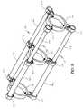
- FIG. 1is a pictorial view of an embodiment of the invention.
- FIG. 2is a pictorial view of the embodiment of FIG. 1 in a second operative position.
- FIG. 3is a pictorial view of another embodiment of the invention.
- FIG. 4is a pictorial view of another embodiment of the invention.
- FIG. 5is a pictorial view of another embodiment of the invention that includes a counterweight.
- FIG. 6is a pictorial view of another embodiment of the invention that includes a counterweight.
- FIG. 7Ais a side elevation of another embodiment of the invention.
- FIG. 7Bis a side elevation of the embodiment of FIG. 7A in a second operative position.
- FIG. 8Ais a side elevation of another embodiment of the invention.
- FIG. 8Bis a side elevation of the embodiment of FIG. 7A in a second operative position.
- FIG. 9is a pictorial view of another embodiment of the invention.
- FIG. 10is a pictorial view of a brake mechanism of another embodiment of the invention.
- FIG. 11is a pictorial view of another brake mechanism of another embodiment of the invention.
- FIG. 1shows a spatial linkage 10 that embodies the invention.
- An inboard gimbal plate 12provides a mechanical ground for the spatial linkage 10 .
- Groundis used to mean a frame of reference for the spatial linkage. While the inboard gimbal plate 12 may move relative to other components, it is considered the immovable foundation of the spatial linkage 10 .
- An outboard gimbal plate 14is coupled to the inboard gimbal plate 12 by three links 16 .
- Each link 16has a longitudinal axis and two pivotal couplings 18 disposed at opposite ends of the longitudinal axis.
- Each link 16is pivotally coupled to the outboard gimbal plate 14 at a first end of the longitudinal axis by one of the pivotal couplings 18 and pivotally coupled to the inboard gimbal plate 12 at a second end of the longitudinal axis opposite the first end by the second pivotal coupling.
- each pivotal couplingallows the link 16 to rotate relative to the coupled gimbal plate 14 with respect to two axes.
- the link 16constrains the motion of the outboard gimbal plate 14 relative to the inboard gimbal plate 12 for all other motions.
- the pivotal coupling 18 illustratedis a clevis pivot.
- the clevisallows the link 16 to rotate only about the axis of the clevis pin.
- the clevisis pivotally coupled to the gimbal plate 12 , 14 allowing the clevis and the coupled link 16 to rotate about a second axis.
- the clevis pivotallows the link 16 to rotate relative to the coupled gimbal plate 14 with respect to two axes while constraining the link with respect to all other movement relative to the coupled gimbal plate 14 .
- the pivotal couplings 18allow the outboard gimbal plate 14 to move relative to the inboard gimbal plate 12 while preventing relative rotation between the outboard gimbal plate and the inboard gimbal plate.
- the outboard gimbal plate 14is always parallel to the inboard gimbal plate 12 .
- a device rigidly supported by the outboard gimbal plate 14will remain in a fixed angular relationship to the grounded inboard gimbal plate 12 .
- the motion of the supported devicewill be limited to translation with two degrees of freedom.
- FIG. 3shows another spatial linkage 310 that embodies the invention.
- an outboard gimbal plate 314is coupled to an inboard gimbal plate 312 by three links 316 . It will be seen that the links need not be in a symmetrical arrangement.
- the pivotal couplings 318are similar to those of the preceding embodiment.
- FIG. 4shows another spatial linkage 410 that embodies the invention.
- an outboard gimbal plate 414is coupled to an inboard gimbal plate 412 by three links 416 .
- the pivotal couplings 418are in the form of universal joints. The range of motion of universal joints may be less than the pivotal couplings shown in the preceding embodiments.
- the spatial linkage 510may be used to provide a counterbalanced support assembly.
- the spatial linkage 510may include a counterweight link 520 having a first end 526 and an opposing second end 522 on a longitudinal axis.
- the counterweight link 520may be pivotally coupled to the outboard gimbal plate 514 at the first end 526 of the longitudinal axis and pivotally coupled to the inboard gimbal plate 512 at a third point 524 between the first end 526 and the second end 522 on the longitudinal axis.
- the distance between the first end 526 and the third point 524 on the longitudinal axis of the counterweight link 520is the same as the distance between the first end 517 and second end 515 of the longitudinal axis for each of the three links 516 .
- the longitudinal axis of the counterweight link 520is parallel to the longitudinal axes of the three links 516 .
- a counterweight 528may coupled to the second end 522 of the counterweight link 520 to counterbalance the spatial linkage 510 and a load supported by the outboard gimbal plate 514 .
- the counterweight link 620may include one of the three links 616 .
- the third point 624 of the longitudinal axis of the counterweight link 620is the same as the second end 615 of the longitudinal axis of the included one of the three links 616 .
- the spatial linkage 710may support a cantilevered load 730 rigidly coupled to the outboard gimbal plate 714 .
- the spatial linkage 710 with the coupled cantilevered load 730may be counterbalanced by a counterweight 728 .
- the cantilevered load 730may have a movable center of gravity.
- the cantilevered load 730may be a load 732 on a linear slide 734 that provides an additional degree of freedom for the load. As the load 732 is moved from a first position shown in FIG. 7A to a second position shown in FIG. 7B the center of gravity of the load moves away from the outboard gimbal plate 714 .
- the spatial linkage 710 with the coupled cantilevered load 730will remain in balance regardless of the movement of the center of gravity of the cantilevered load. It will be appreciated that a load on a linear slide may require a counterbalance with respect to the slide if the slide is not maintained perpendicular to gravity (horizontal).
- the cantilevered load 730is rigidly coupled to and supported by the outboard gimbal plate 714 .
- the outboard gimbal platesupports the weight of the load 730 as indicated by the vector W in the direction of gravity.
- the weight of the load 730is counterbalanced by the counterweight 728 as indicated by the second vector W. (The counterweight also counterbalances the weight of spatial linkage 710 .)
- the outboard gimbal plate 714further supports a rotational force due to the displacement of the center of gravity of the load from the outboard gimbal plate indicated by the vector M 1 744 .
- the rotational force on the outboard gimbal plateincreases as indicated by the vector M 2 744 ′ in FIG. 7B .
- the three links 716constrain the outboard gimbal plate 714 to remain parallel to the inboard gimbal plate 712 . Therefore the rotational forces on the outboard gimbal plate 714 are transferred to the inboard gimbal plate 712 as indicated by the equal and opposite vector M 1 746 .
- the inboard gimbal plate 712is the grounded member of the spatial linkage 710 and it provides the necessary reaction force to any applied load. Thus, changes in the center of gravity of the load 730 only change the rotational forces on the gimbal plates which are supported to ground. Only the unchanging weight of the load 730 is supported by the counterweight. It will be appreciated that while inboard gimbal plate 712 is the ground member of the spatial linkage 710 , it may be movably supported.
- the inboard gimbal plate 812 of the spatial linkage 810may supported by a grounded sliding support 850 such that the inboard gimbal plate is movable laterally along the length of the sliding support and is constrained in all other lateral directions and rotations.
- the load supported by the outboard gimbal plate 814may be a surgical robotic arm 830 .
- the arrangement illustrated in FIGS. 8A and 8Bmay be used as a setup joint system for the robotic arm 830 . It will be appreciated that the robotic arm 830 could be connected to the outboard gimbal plate 814 with a linear slide similar to that illustrated in FIGS. 7A and 7B to provide an additional degree of freedom.
- the changing center of gravity of the loadcreates a changing gravitational moment load on the outboard gimbal plate 814 that is reacted by the grounded inboard gimbal plate 812 as previously described.
- the load of the surgical robotic arm 830remains counterbalanced by the counterweight 828 regardless of the movement of the surgical robotic arm or movement of the inboard gimbal plate 812 laterally along the sliding support 850 because the inboard gimbal plate is constrained from rotating.
- the inboard gimbal plate 812remains grounded through the grounded sliding support 850 so that it can react the changing moment at the outboard gimbal plate 814 created by the changing center of gravity of the load 830 .
- a counterbalancemay be provided as part of the sliding support to maintain the position of the spatial linkage 810 on the sliding support.
- the counterbalancemay be in the form of a sliding counterweight 852 coupled to the sliding support 850 such that the counterweight is movable laterally along the length of the sliding support.
- the counterweight 852is coupled to the inboard gimbal plate 812 such that the counterweight provides a force on the inboard gimbal plate that is equal and opposite to the gravitational force on the inboard gimbal plate.
- the counterweight 852has a mass equal to the mass of all components attached to and including the inboard gimbal plate 812 .
- the counterweight 852 and total outboard mass of components attached to and including the inboard gimbal plate 812are equally affected by gravity because they are coupled to the sliding support 850 such that they are both inclined equally.
- a cable 854 and pulley 856 arrangementallows the counterweight 852 to counteract the gravitational forces on the inboard gimbal plate 812 .
- Two pulleysmay support the cable in a loop configuration to provide a counterbalance inclining the sliding support in either direction and to maintain cable tension when the sliding support is substantially horizontal.
- the gimbal plates and linksprovide two degrees of freedom for the load supported by the outboard gimbal plate.
- the inboardmay be gimbal plate coupled to ground with a sliding connection to provide a third degree of freedom. In some applications it may be desirable to provide a third degree of freedom without the use of a sliding connection.
- FIG. 9shows an embodiment of the spatial linkage in which a distance between a first end 960 and a second end 964 of the longitudinal axis of each link 916 is adjustable such that the distance remains equal for each of the three links.
- each link 916includes an outer portion 916 a and an inner portion 916 b that slides within the outer portion to provide a telescoping link.
- the linkmay use a mechanism such as a ball spline to provide the sliding connection between the outer and inner portions of the link.
- An intermediate gimbal plate 913supports the ends 962 of the outer portions 916 a of the links with a fixed distance between the outer ends thus constraining the inner portions 916 b of the links to extend equally from the outer portions. This maintains an equal distance between the first end 960 and second end 964 for each of the three links 916 .
- a double acting hydraulic pistonmay be provided in each link.
- the inboard chamber of one pistonmay be coupled to the outboard chamber of an adjacent piston to cause all pistons and their associated links to extend and retract in unison.
- a cable and pulley systemmay be used to cause all links to extend and retract by the same amount. It will be appreciated that a moving counterweight is required to counterbalance a spatial linkage with adjustable length links.
- FIG. 10shows one end of a spatial linkage 1000 that includes a pivotal coupling 1019 with a brake. It may be seen that the link 1017 coupled to the braked pivotal coupling 1019 is enlarged as compared to the remaining links 1016 coupled to unbraked pivotal couplings 1018 . Brake mechanisms 1070 , 1072 are provided on each of the rotational axes of the pivotal coupling 1019 to prevent rotation about each axis when the brake mechanism is engaged for that axis.
- the brake mechanismmay be any mechanism that prevents rotation of an axis of the pivotal coupling.
- the brakemay be manually actuated or it may be remotely actuated by means such as, but not limited to, electric, hydraulic, pneumatic, magnetic, or mechanical means.
- FIG. 11shows another pivotal coupling 1118 with a brake.
- a pivot block 1182is rotatably supported by a first axle 1178 fixedly coupled to one of the gimbal plates 1112 of the spatial linkage.
- a yoke 1186is rotatably supported by a discontinuous second axle 1180 , 1184 coupled to the pivot block 1182 . The yoke 1186 would be coupled to one of the links of the spatial linkage.
- a spherical braking surface 1176is fixedly coupled to the first axle 1178 .
- the spherical braking surface 1176is fixed with respect to the gimbal plate 1112 .
- the spherical braking surfacemay be a portion of a complete spherical surface.
- the yoke 1186supports a brake mechanism 1170 .
- the brake mechanismpresses a brake pad 1174 against the spherical braking surface 1176 to prevent relative motion between the yoke 1186 and the gimbal plate 1112 .
- the brakemay be manually actuated or it may be remotely actuated by means such as, but not limited to, electric, hydraulic, pneumatic, magnetic, or mechanical means.
- a third degree of freedomsuch as an outboard or inboard sliding support or coupling or extensible links
- the brake on the third degree of freedommay be coupled to the brake that locks the outboard gimbal plate in a fixed position so that a user can lock all degrees freedom with a single action.
- the disclosed spatial linkagemay be used for supporting a robotic arm to provide freedom of motion for setting a position of the robotic arm.
- the outboard gimbal platemay rigidly support the robotic arm.
- the inboard gimbal platemay provide a ground support for the robotic arm.
- Three or more links of equal lengthcouple the outboard gimbal plate to the inboard gimbal plate.
- the linksare coupled to the gimbal plates with pivotal couplings that allow the outboard gimbal plate to move relative to the inboard gimbal plate and preventing relative rotation between the outboard gimbal plate and the inboard gimbal plate.
- the supported robotic armmay be positioned with respect to the grounded inboard gimbal plate while remaining in a fixed orientation relative to the inboard gimbal plate.
Landscapes
- Health & Medical Sciences (AREA)
- Surgery (AREA)
- Life Sciences & Earth Sciences (AREA)
- Engineering & Computer Science (AREA)
- Medical Informatics (AREA)
- General Health & Medical Sciences (AREA)
- Biomedical Technology (AREA)
- Heart & Thoracic Surgery (AREA)
- Nuclear Medicine, Radiotherapy & Molecular Imaging (AREA)
- Molecular Biology (AREA)
- Animal Behavior & Ethology (AREA)
- Veterinary Medicine (AREA)
- Public Health (AREA)
- Robotics (AREA)
- Oral & Maxillofacial Surgery (AREA)
- Pathology (AREA)
- Manipulator (AREA)
- Transmission Devices (AREA)
Abstract
Description
Claims (20)
Priority Applications (3)
| Application Number | Priority Date | Filing Date | Title |
|---|---|---|---|
| US11/864,702US7677129B2 (en) | 2007-09-28 | 2007-09-28 | Multiaxis counterbalance and positioning system using a spatial linkage |
| PCT/US2008/076129WO2009045698A1 (en) | 2007-09-28 | 2008-09-12 | Multiaxis counterbalance and positioning system using a spatiial linkage |
| US12/693,329US8342054B2 (en) | 2007-09-28 | 2010-01-25 | Multiaxis counterbalance and positioning system using a spatial linkage |
Applications Claiming Priority (1)
| Application Number | Priority Date | Filing Date | Title |
|---|---|---|---|
| US11/864,702US7677129B2 (en) | 2007-09-28 | 2007-09-28 | Multiaxis counterbalance and positioning system using a spatial linkage |
Related Child Applications (1)
| Application Number | Title | Priority Date | Filing Date |
|---|---|---|---|
| US12/693,329DivisionUS8342054B2 (en) | 2007-09-28 | 2010-01-25 | Multiaxis counterbalance and positioning system using a spatial linkage |
Publications (2)
| Publication Number | Publication Date |
|---|---|
| US20090084216A1 US20090084216A1 (en) | 2009-04-02 |
| US7677129B2true US7677129B2 (en) | 2010-03-16 |
Family
ID=40089987
Family Applications (2)
| Application Number | Title | Priority Date | Filing Date |
|---|---|---|---|
| US11/864,702Active2027-11-08US7677129B2 (en) | 2007-09-28 | 2007-09-28 | Multiaxis counterbalance and positioning system using a spatial linkage |
| US12/693,329Active2028-08-04US8342054B2 (en) | 2007-09-28 | 2010-01-25 | Multiaxis counterbalance and positioning system using a spatial linkage |
Family Applications After (1)
| Application Number | Title | Priority Date | Filing Date |
|---|---|---|---|
| US12/693,329Active2028-08-04US8342054B2 (en) | 2007-09-28 | 2010-01-25 | Multiaxis counterbalance and positioning system using a spatial linkage |
Country Status (2)
| Country | Link |
|---|---|
| US (2) | US7677129B2 (en) |
| WO (1) | WO2009045698A1 (en) |
Cited By (4)
| Publication number | Priority date | Publication date | Assignee | Title |
|---|---|---|---|---|
| US20100077877A1 (en)* | 2008-09-26 | 2010-04-01 | Ming-Hung Hsieh | Rotary micro-adjustment mechanism for a synchronous double-drive positioning platform |
| US8807910B1 (en)* | 2007-05-31 | 2014-08-19 | Thomas V. Roden | Variable counterweight system for a material handling vehicle |
| US9486189B2 (en) | 2010-12-02 | 2016-11-08 | Hitachi Aloka Medical, Ltd. | Assembly for use with surgery system |
| US20200009746A1 (en)* | 2018-07-03 | 2020-01-09 | Swift Engineering, Inc. | Robotic forearms |
Families Citing this family (4)
| Publication number | Priority date | Publication date | Assignee | Title |
|---|---|---|---|---|
| EP2943109A4 (en)* | 2013-01-08 | 2016-08-24 | Mst Medical Surgery Technologies Ltd | SUPPORT AND POSITIONING ELEMENT FOR ENDOSCOPE MANUFACTURING SYSTEM |
| CN113616337B (en)* | 2013-02-15 | 2025-02-07 | 直观外科手术操作公司 | System and method for proximal control of surgical instruments |
| CN104882061B (en)* | 2015-06-17 | 2017-07-25 | 上海大学 | Land experiment system applied to two-degree-of-freedom mobile robot module |
| CA3015089A1 (en) | 2017-08-23 | 2019-02-23 | Memic Innovative Surgery Ltd. | Tools and methods for vaginal access |
Citations (14)
| Publication number | Priority date | Publication date | Assignee | Title |
|---|---|---|---|---|
| US3419238A (en)* | 1967-06-21 | 1968-12-31 | Air Force Usa | Parallel platform linkages for shock isolation systems |
| US3721416A (en)* | 1970-12-04 | 1973-03-20 | Conco Inc | Loading balancer |
| US4659278A (en)* | 1984-02-27 | 1987-04-21 | Stahl Aufzuge & Co. KG | Manipulator based on the pantograph principle |
| US4739241A (en)* | 1986-10-09 | 1988-04-19 | Georgia Tech Research Corporation | Spherical motor particularly adapted for robotics |
| EP0595291A1 (en) | 1992-10-30 | 1994-05-04 | International Business Machines Corporation | Improved remote center-of-motion robot for surgery |
| WO1997013997A1 (en) | 1995-10-12 | 1997-04-17 | Leica Ag | Stand |
| US5740699A (en)* | 1995-04-06 | 1998-04-21 | Spar Aerospace Limited | Wrist joint which is longitudinally extendible |
| US6210097B1 (en)* | 1999-06-25 | 2001-04-03 | Samsung Electronics Co., Ltd. | Burden loading robot having balancer for compensating for off-center loading of weight |
| US20040024385A1 (en)* | 1999-11-12 | 2004-02-05 | Microdexterity Systems, Inc. | Manipulator |
| US20040111113A1 (en) | 2002-12-09 | 2004-06-10 | The University Of Tokyo | High-rigidity forceps tip assembly for active forceps and active forceps equipped with the same |
| US20050072261A1 (en)* | 2003-10-03 | 2005-04-07 | Fanuc Ltd. | Distribution equipment for robot |
| US20060156850A1 (en)* | 2002-10-02 | 2006-07-20 | Christian Mueller | Test head positioning apparatus |
| US20060196299A1 (en)* | 2005-01-27 | 2006-09-07 | John Taboada | Seven Axis End Effector Articulating Mechanism |
| US20080028881A1 (en)* | 2003-12-03 | 2008-02-07 | Keisuke Sone | Linkage System |
Family Cites Families (4)
| Publication number | Priority date | Publication date | Assignee | Title |
|---|---|---|---|---|
| US4666364A (en)* | 1984-06-19 | 1987-05-19 | Stahl Aufzge Gmbh & Co. Kg | Low friction cylinder for manipulators, based on the pantograph principle and equipped with a pneumatic balancer control |
| EP0699053B1 (en)* | 1993-05-14 | 1999-03-17 | Sri International | Surgical apparatus |
| JP2002165804A (en)* | 2000-09-22 | 2002-06-11 | Mitaka Koki Co Ltd | Medical stand device |
| JP2008009877A (en)* | 2006-06-30 | 2008-01-17 | Brother Ind Ltd | Image processing apparatus, image processing method, and program |
- 2007
- 2007-09-28USUS11/864,702patent/US7677129B2/enactiveActive
- 2008
- 2008-09-12WOPCT/US2008/076129patent/WO2009045698A1/enactiveApplication Filing
- 2010
- 2010-01-25USUS12/693,329patent/US8342054B2/enactiveActive
Patent Citations (14)
| Publication number | Priority date | Publication date | Assignee | Title |
|---|---|---|---|---|
| US3419238A (en)* | 1967-06-21 | 1968-12-31 | Air Force Usa | Parallel platform linkages for shock isolation systems |
| US3721416A (en)* | 1970-12-04 | 1973-03-20 | Conco Inc | Loading balancer |
| US4659278A (en)* | 1984-02-27 | 1987-04-21 | Stahl Aufzuge & Co. KG | Manipulator based on the pantograph principle |
| US4739241A (en)* | 1986-10-09 | 1988-04-19 | Georgia Tech Research Corporation | Spherical motor particularly adapted for robotics |
| EP0595291A1 (en) | 1992-10-30 | 1994-05-04 | International Business Machines Corporation | Improved remote center-of-motion robot for surgery |
| US5740699A (en)* | 1995-04-06 | 1998-04-21 | Spar Aerospace Limited | Wrist joint which is longitudinally extendible |
| WO1997013997A1 (en) | 1995-10-12 | 1997-04-17 | Leica Ag | Stand |
| US6210097B1 (en)* | 1999-06-25 | 2001-04-03 | Samsung Electronics Co., Ltd. | Burden loading robot having balancer for compensating for off-center loading of weight |
| US20040024385A1 (en)* | 1999-11-12 | 2004-02-05 | Microdexterity Systems, Inc. | Manipulator |
| US20060156850A1 (en)* | 2002-10-02 | 2006-07-20 | Christian Mueller | Test head positioning apparatus |
| US20040111113A1 (en) | 2002-12-09 | 2004-06-10 | The University Of Tokyo | High-rigidity forceps tip assembly for active forceps and active forceps equipped with the same |
| US20050072261A1 (en)* | 2003-10-03 | 2005-04-07 | Fanuc Ltd. | Distribution equipment for robot |
| US20080028881A1 (en)* | 2003-12-03 | 2008-02-07 | Keisuke Sone | Linkage System |
| US20060196299A1 (en)* | 2005-01-27 | 2006-09-07 | John Taboada | Seven Axis End Effector Articulating Mechanism |
Non-Patent Citations (3)
| Title |
|---|
| PCT/US08/76129 International Search Report, mailed Feb. 12, 2009, 4 pages. |
| PCT/US08/76129 Written Opinion of the International Search Authority, mailed Feb. 12, 2009, 6 pages. |
| Vertut, Jean and Philippe Coiffet, Teleoperation and Robotics: Evolution and Development, English translation Prentice-Hall, Inc., Inglewood Cliffs, NJ, USA, 1986. |
Cited By (4)
| Publication number | Priority date | Publication date | Assignee | Title |
|---|---|---|---|---|
| US8807910B1 (en)* | 2007-05-31 | 2014-08-19 | Thomas V. Roden | Variable counterweight system for a material handling vehicle |
| US20100077877A1 (en)* | 2008-09-26 | 2010-04-01 | Ming-Hung Hsieh | Rotary micro-adjustment mechanism for a synchronous double-drive positioning platform |
| US9486189B2 (en) | 2010-12-02 | 2016-11-08 | Hitachi Aloka Medical, Ltd. | Assembly for use with surgery system |
| US20200009746A1 (en)* | 2018-07-03 | 2020-01-09 | Swift Engineering, Inc. | Robotic forearms |
Also Published As
| Publication number | Publication date |
|---|---|
| US20100116082A1 (en) | 2010-05-13 |
| US20090084216A1 (en) | 2009-04-02 |
| US8342054B2 (en) | 2013-01-01 |
| WO2009045698A1 (en) | 2009-04-09 |
Similar Documents
| Publication | Publication Date | Title |
|---|---|---|
| US8342054B2 (en) | Multiaxis counterbalance and positioning system using a spatial linkage | |
| US7665702B2 (en) | Medical support | |
| US11969889B2 (en) | Lever actuated gimbal plate | |
| CN102579133B (en) | Modular manipulator support for robotic surgery | |
| EP3479775B1 (en) | Surgical robot and mechanical arm thereof | |
| US5253832A (en) | Spring counterbalanced boom suspension system | |
| US8506180B2 (en) | Extendable camera support and stabilization apparatus | |
| US4881709A (en) | Stand mechanism for a medical optical equipment | |
| JP2013144149A (en) | Compact counter balance for robotic surgical system | |
| JPH06217993A (en) | Position detecting device for medical treatment | |
| JP2001066517A (en) | Ceiling attaching device | |
| EP0293227A2 (en) | Stand mechanism for a medical optical equipment | |
| US6142667A (en) | Gas-spring assisted, counter-balanced L-arm assembly for fluoroscopic imaging | |
| US10353165B2 (en) | Stand equipped with counterbalance unit | |
| JP2013240613A (en) | Weight compensation type holder | |
| JP2017124184A (en) | stand | |
| JP4213902B2 (en) | Mounting platform, especially for operating microscope | |
| JP4441057B2 (en) | Support device for medical optical equipment | |
| US10400944B2 (en) | Counterbalance system and/or a method for counterbalancing a load | |
| US6532108B1 (en) | Operating microscope stand for X-Y displacement | |
| US5642220A (en) | Microscope balance compensator | |
| JP5543691B2 (en) | MEDICAL IMAGING DEVICE INCLUDING MEDICAL IMAGE RECEIVER AND COMPUTER ACCESSABLE MEDIUM WITH EXECUTABLE INSTRUMENTS FOR POSITIONING MEDICAL X-RAY IMAGE RECEPTOR | |
| JP3605057B2 (en) | Medical manipulator system | |
| JP3350112B2 (en) | Mechanical control unit for operating microscope combined with pedestal | |
| US11199289B2 (en) | Apparatus, surgical microscopy system, and method for compensating a balancing error in a stand for a surgical microscope |
Legal Events
| Date | Code | Title | Description |
|---|---|---|---|
| AS | Assignment | Owner name:INTUITIVE SURGICAL, INC., CALIFORNIA Free format text:ASSIGNMENT OF ASSIGNORS INTEREST;ASSIGNORS:SCHENA, BRUCE MICHAEL;DEVENGENZO, ROMAN;REEL/FRAME:020204/0645 Effective date:20071009 Owner name:INTUITIVE SURGICAL, INC.,CALIFORNIA Free format text:ASSIGNMENT OF ASSIGNORS INTEREST;ASSIGNORS:SCHENA, BRUCE MICHAEL;DEVENGENZO, ROMAN;REEL/FRAME:020204/0645 Effective date:20071009 | |
| FEPP | Fee payment procedure | Free format text:PAYOR NUMBER ASSIGNED (ORIGINAL EVENT CODE: ASPN); ENTITY STATUS OF PATENT OWNER: LARGE ENTITY | |
| STCF | Information on status: patent grant | Free format text:PATENTED CASE | |
| AS | Assignment | Owner name:INTUITIVE SURGICAL OPERATIONS, INC.,CALIFORNIA Free format text:ASSIGNMENT OF ASSIGNORS INTEREST;ASSIGNOR:INTUITIVE SURGICAL, INC.;REEL/FRAME:024468/0890 Effective date:20100219 Owner name:INTUITIVE SURGICAL OPERATIONS, INC., CALIFORNIA Free format text:ASSIGNMENT OF ASSIGNORS INTEREST;ASSIGNOR:INTUITIVE SURGICAL, INC.;REEL/FRAME:024468/0890 Effective date:20100219 | |
| FPAY | Fee payment | Year of fee payment:4 | |
| MAFP | Maintenance fee payment | Free format text:PAYMENT OF MAINTENANCE FEE, 8TH YEAR, LARGE ENTITY (ORIGINAL EVENT CODE: M1552) Year of fee payment:8 | |
| MAFP | Maintenance fee payment | Free format text:PAYMENT OF MAINTENANCE FEE, 12TH YEAR, LARGE ENTITY (ORIGINAL EVENT CODE: M1553); ENTITY STATUS OF PATENT OWNER: LARGE ENTITY Year of fee payment:12 |