US7676953B2 - Calibration and metering methods for wood kiln moisture measurement - Google Patents
Calibration and metering methods for wood kiln moisture measurementDownload PDFInfo
- Publication number
- US7676953B2 US7676953B2US11/617,910US61791006AUS7676953B2US 7676953 B2US7676953 B2US 7676953B2US 61791006 AUS61791006 AUS 61791006AUS 7676953 B2US7676953 B2US 7676953B2
- Authority
- US
- United States
- Prior art keywords
- cabling
- impedance
- values
- determining
- calibration
- Prior art date
- Legal status (The legal status is an assumption and is not a legal conclusion. Google has not performed a legal analysis and makes no representation as to the accuracy of the status listed.)
- Active, expires
Links
- 238000000034methodMethods0.000titleclaimsabstractdescription189
- 238000005259measurementMethods0.000titleclaimsabstractdescription139
- 239000002023woodSubstances0.000titledescription3
- 238000001035dryingMethods0.000claimsabstractdescription72
- 239000003990capacitorSubstances0.000claimsdescription114
- 239000004020conductorSubstances0.000claimsdescription36
- 238000004891communicationMethods0.000claimsdescription27
- 238000012544monitoring processMethods0.000claimsdescription25
- 230000005284excitationEffects0.000claimsdescription22
- 230000001419dependent effectEffects0.000claimsdescription19
- 238000012937correctionMethods0.000claimsdescription17
- 230000004044responseEffects0.000claimsdescription16
- 238000003860storageMethods0.000description42
- 238000002847impedance measurementMethods0.000description20
- 238000013519translationMethods0.000description10
- 238000009434installationMethods0.000description8
- 230000008569processEffects0.000description8
- 229910000831SteelInorganic materials0.000description4
- 238000010586diagramMethods0.000description4
- 239000010959steelSubstances0.000description4
- 239000000654additiveSubstances0.000description3
- 230000000996additive effectEffects0.000description3
- 230000008901benefitEffects0.000description3
- 230000003116impacting effectEffects0.000description3
- 230000000977initiatory effectEffects0.000description3
- 230000008054signal transmissionEffects0.000description3
- 238000012360testing methodMethods0.000description3
- WXOMTJVVIMOXJL-BOBFKVMVSA-AO.O.O.O.O.O.O.O.O.O.O.O.O.O.O.O.O.O.O.O.O.O.O[Al](O)O.O[Al](O)O.O[Al](O)O.O[Al](O)O.O[Al](O)O.O[Al](O)O.O[Al](O)O.O[Al](O)O.O[Al](O)OS(=O)(=O)OC[C@H]1O[C@@H](O[C@]2(COS(=O)(=O)O[Al](O)O)O[C@H](OS(=O)(=O)O[Al](O)O)[C@@H](OS(=O)(=O)O[Al](O)O)[C@@H]2OS(=O)(=O)O[Al](O)O)[C@H](OS(=O)(=O)O[Al](O)O)[C@@H](OS(=O)(=O)O[Al](O)O)[C@@H]1OS(=O)(=O)O[Al](O)OChemical compoundO.O.O.O.O.O.O.O.O.O.O.O.O.O.O.O.O.O.O.O.O.O.O[Al](O)O.O[Al](O)O.O[Al](O)O.O[Al](O)O.O[Al](O)O.O[Al](O)O.O[Al](O)O.O[Al](O)O.O[Al](O)OS(=O)(=O)OC[C@H]1O[C@@H](O[C@]2(COS(=O)(=O)O[Al](O)O)O[C@H](OS(=O)(=O)O[Al](O)O)[C@@H](OS(=O)(=O)O[Al](O)O)[C@@H]2OS(=O)(=O)O[Al](O)O)[C@H](OS(=O)(=O)O[Al](O)O)[C@@H](OS(=O)(=O)O[Al](O)O)[C@@H]1OS(=O)(=O)O[Al](O)OWXOMTJVVIMOXJL-BOBFKVMVSA-A0.000description2
- 230000006978adaptationEffects0.000description2
- 230000005540biological transmissionEffects0.000description2
- 238000013461designMethods0.000description2
- 230000000694effectsEffects0.000description2
- 238000011156evaluationMethods0.000description2
- 238000012423maintenanceMethods0.000description2
- 238000012986modificationMethods0.000description2
- 230000004048modificationEffects0.000description2
- 238000012545processingMethods0.000description2
- 239000000565sealantSubstances0.000description2
- XLYOFNOQVPJJNP-UHFFFAOYSA-NwaterSubstancesOXLYOFNOQVPJJNP-UHFFFAOYSA-N0.000description2
- 241000167854Bourreria succulentaSpecies0.000description1
- RYGMFSIKBFXOCR-UHFFFAOYSA-NCopperChemical compound[Cu]RYGMFSIKBFXOCR-UHFFFAOYSA-N0.000description1
- 206010035148PlagueDiseases0.000description1
- 241000607479Yersinia pestisSpecies0.000description1
- 230000004913activationEffects0.000description1
- 230000002411adverseEffects0.000description1
- 238000013459approachMethods0.000description1
- 238000004364calculation methodMethods0.000description1
- 238000006243chemical reactionMethods0.000description1
- 235000019693cherriesNutrition0.000description1
- 239000000470constituentSubstances0.000description1
- 230000007797corrosionEffects0.000description1
- 238000005260corrosionMethods0.000description1
- 238000013480data collectionMethods0.000description1
- 238000013500data storageMethods0.000description1
- 230000001934delayEffects0.000description1
- 238000010981drying operationMethods0.000description1
- 230000002708enhancing effectEffects0.000description1
- 231100001261hazardousToxicity0.000description1
- 238000011065in-situ storageMethods0.000description1
- 238000009413insulationMethods0.000description1
- 230000003993interactionEffects0.000description1
- 230000013011matingEffects0.000description1
- 230000008707rearrangementEffects0.000description1
- 238000009877renderingMethods0.000description1
- 238000005070samplingMethods0.000description1
- 229910001220stainless steelInorganic materials0.000description1
- 230000009466transformationEffects0.000description1
Images


Classifications
- G—PHYSICS
- G01—MEASURING; TESTING
- G01N—INVESTIGATING OR ANALYSING MATERIALS BY DETERMINING THEIR CHEMICAL OR PHYSICAL PROPERTIES
- G01N33/00—Investigating or analysing materials by specific methods not covered by groups G01N1/00 - G01N31/00
- G01N33/46—Wood
- G—PHYSICS
- G01—MEASURING; TESTING
- G01N—INVESTIGATING OR ANALYSING MATERIALS BY DETERMINING THEIR CHEMICAL OR PHYSICAL PROPERTIES
- G01N27/00—Investigating or analysing materials by the use of electric, electrochemical, or magnetic means
- G01N27/02—Investigating or analysing materials by the use of electric, electrochemical, or magnetic means by investigating impedance
- G01N27/22—Investigating or analysing materials by the use of electric, electrochemical, or magnetic means by investigating impedance by investigating capacitance
- G01N27/223—Investigating or analysing materials by the use of electric, electrochemical, or magnetic means by investigating impedance by investigating capacitance for determining moisture content, e.g. humidity
Definitions
- the present inventionis directed to calibrating measurements of signals received from sensors for measuring the moisture content of drying lumber, and in particular, to determining adjustments of such measurements to compensate for transmission induced variations in the signals, and more particularly, to determining such adjustment due to varying and/or long lengths of cabling used to transmit the signals.
- Final moisture content of kiln-dried lumberis extremely critical to ensure optimal performance of the lumber in its end-use. Lumber that is too wet (under-dried) is prone to mold growth that can significantly compromise the lumber's strength, durability, and appearance. Under-dried lumber will also experience shrinkage as it dries to equilibrium, resulting in dimensional problems. Lumber that is too dry, or over-dried, will tend to warp and crack, also causing dimensional problems and rendering it less useful in most applications. Over-drying also results in lost productivity, and increased energy costs.
- Such prior art systemsuse electrical metering devices to measure the moisture content of lumber as it dries in a kiln. In most (if not all) cases, these electrical metering arrangements involve placement of steel plates in the lumber to form a capacitor. The various systems then employ some form of cabling to carry the electrical signal from the plates back to such a metering device. The metering device measures the electrical capacitance of the circuit formed by the steel plates and the lumber. The capacitance is closely related to the moisture content in the lumber, so the metering device output can be appropriately scaled to read out in terms of moisture content.
- the meterprovides the capacitance values from the plates to either a PC (i.e., personal computer) or a PLC-based controller (i.e., programmable logic controller).
- a PCi.e., personal computer
- PLC-based controlleri.e., programmable logic controller
- the transform from capacitance to moisture contentis performed either in the meter or in the PLC/PC, and the moisture content values are then used by a kiln controller (a separate control system) to identify when no further drying of the lumber is desired.
- prior art systemsinclude multiple metering devices (each also referred to herein as a capacitive meter, or evaluator) mounted on either the kiln interior or the kiln exterior.
- metering deviceseach also referred to herein as a capacitive meter, or evaluator
- the electrical signals to and from the steel plates, inserted in the kiln stackstravel only a very short distance, e.g., less than 50 linear feet via carefully isolated conductive wires.
- the wiring (also referred to as cabling herein) from the capacitor plates to the metering deviceis a significant design issue in establishing a reliable and accurate metering circuit.
- numerous issuesmust be considered in the design of the cabling, including the following:
- both non-insulated stranded wire and insulated stranded wireare susceptible to electrical noise which can further compromise the validity of the capacitance signal.
- coaxial cableis far more resistant to electrical noise than non-insulated stranded wire and stranded wire and communicates a superior signal (e.g., a higher signal to noise ratio)
- the use of coaxial cablecan be difficult for prior art kiln moisture monitoring systems in that there are high capacitance levels generated in coaxial cable that can not be easily removed by the simple prior art calibration methods.
- the present disclosuredescribes a lumber moisture measurement system (also referred to herein as a “moisture measurement system”, and a “meter” that includes highly accurate calibration methods to standardize the signal response in each of one or more channels (i.e., a channel as described hereinabove) so that the output (i.e., capacitance measurements and/or lumber moisture content values) from the meter is substantially independent of signal transmission peculiarities or differences that occur on one channel and not another channel. More specifically, for each channel, capacitances generated in cables, such as coaxial cables, can be effectively cancelled.
- calibration methods disclosed hereinallow for long lengths of coaxial cable (e.g., up to 1000 linear feet) to be effectively used in the circuitry for monitoring lumber drying in a kiln without the cable length adversely affecting the lumber moisture content measurements determined by the meter.
- the long cable lengthsfacilitate the centralizing of kiln monitoring electronics, e.g., such as metering devices, in an enclosure satisfying NEMA (National Electrical Manufacturers Association) standards, and in particular, such an enclosure may be in a wood drying monitoring control room, wherein such electronics are not subject to weather variations and are easily accessible for maintenance.
- NEMANational Electrical Manufacturers Association
- the moisture measurement system disclosed hereinalso includes shielded coaxial cabling, encased in conduit, for making the connection to the capacitor plates in the kiln. This offers a high degree of electrical noise resistance, and the insulation precludes the possibility of electrical shorts. Since the cabling is now insulated, a tensioned swing-arm device is no longer required, removing the mechanical complications associated with this device. Installation of insulated electrical stand-offs is also no longer required.
- coaxial cablingencased in conduit, is used to transport signals between a wood drying monitoring meter, and a connection to a pair of capacitor plates in a kiln.
- the present disclosuredescribes three embodiments by which metering (i.e., monitoring) of moisture in the lumber within a kiln can be performed, wherein each one of the three embodiments is suitable for one or more of the calibration methods being described.
- the methods described in the three embodimentscan include changes in the metering electronics and cabling, primarily including changes to the sensor measurement portion of the moisture measurement system.
- whichever embodiment is employedis substantially transparent in that each embodiment provides substantially identical functionality and user interaction appearance.
- the three metering embodimentsare:
- the present disclosurefurther describes three alternate/optional calibration methods by which the cabling (e.g., the length thereof) for a channel can be calibrated so that the electrical properties of the cabling (and cabling variations between channels) do not detrimentally affect a determination of the moisture in the lumber being dried in a kiln.
- These three calibration methodscan be described as follows:
- the novel moisture measurement system disclosed hereinincludes centralized metering electronics (e.g., in a NEMA enclosure of a control room) instead of distributing the meters adjacent their corresponding kilns as provided by prior art systems. Accordingly, external installation and servicing of meters is no longer required. Any service required to the metering equipment can be done within the control room. Thus, since the electronics are now enclosed in a controlled environment, substantially all weather-related meter failures caused by ice, water, wind, etc. are prevented. Moreover, moisture measurement system installation and maintenance access becomes far safer and much easier. Additionally, a reduced amount of moisture monitoring electronics is required because most (if not all) of the weather sensitive electronics can be centralized.
- the moisture measurement system disclosed hereinadditionally includes conduit and cabling that can be installed external to the kiln while the kiln is still operating, thus making kiln down time very short for the installation.
- All the conduit, cabling, and connectorsmay be standard electrical equipment that can be installed by any electrician, so highly specialized knowledge and equipment (such as electrical insulating stand offs and swing arms) are not needed.
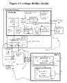
- FIG. 1Ais a block diagram showing the components of the moisture measurement system, configured as a voltage divider circuit.
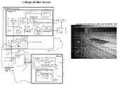
- FIG. 1Bis a block diagram showing the components of the moisture measurement system, configured as a bridge circuit.
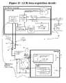
- FIG. 1Cis a block diagram showing the components of the moisture measurement system, configured as a LCR data acquisition circuit.
- FIG. 2shows a sensor plate inserted in a kiln stack of lumber, with the cable attached via a spring-clip connector.
- FIG. 3Ais a schematic showing the circuit model for the voltage divider metering method with an excited coaxial shield.
- FIG. 3Bis a schematic showing the circuit model for the voltage divider metering method with a grounded coaxial shield.
- FIG. 3Cis a schematic showing the circuit model for the bridge or LCR metering method with a grounded coaxial shield.
- FIGS. 4A through 4Ddisclose a flowchart describing the calibration of the voltage divider metering embodiment ( FIG. 1A ), using a resistor-capacitor network, wherein the coaxial cabling is electrically excited.
- FIGS. 5A and 5Bis a flowchart describing the calibration using the impedance measurement method.
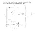
- FIG. 6Ais a schematic showing the circuit model for the “short-open” calibration method with a grounded coaxial shield.
- FIG. 6Bis a schematic showing the circuit model for the “short-open” calibration method with a grounded coaxial shield, to be used in the LCR metering or bridge metering embodiments.
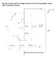
- FIGS. 7A and 7Bis a flowchart describing the calibration using the “short-open” method, wherein the coaxial cabling has a grounded shield 90 .
- FIG. 8shows an exterior view of the calibration box 704 .
- FIG. 9shows a high level circuit diagram of the calibration box 704 .
- FIGS. 1A , 1 B and 1 Cshow a different embodiment of a moisture measurement system 10 .
- FIG. 1Ashows an embodiment of the moisture measurement system 10 configured as a voltage divider.
- the moisture measurement system 10includes a kiln moisture system 11 that performs key services including: moisture metering (i.e., receiving moisture readings from moisture sensors 20 , 40 within the drying lumber 110 , 120 , cf. FIGS. 1 and 2 ), data collection, data storage, interfacing with an operator, and communicating between the various components of the moisture measurement system.
- the kiln moisture system 11signally communicates with kiln capacitors 17 (e.g., sensor plates 20 , 40 ), wherein each capacitor 17 includes a pair of the sensor plates (e.g., the pair 20 and 30 , or the pair 40 and 50 ) spaced apart by a predetermined amount of lumber (e.g., 110 or 120 ).
- the sensor plates of such a pairmay be spaced apart by, e.g., a stack of lumber in a range of 30 to 60 inches thick, and more preferably about 35 to 50 inches thick, and most preferably approximately 40 inches thick.
- the signal communication between the capacitor 17 and the kiln moisture system 11may be via a multiplexer unit 70 that serves as a switching device to allow the kiln moisture system 11 to interface with multiple communication channels provided on the communication cabling 78 a and 78 b , wherein for each of the sensor plates 20 and 40 (i.e., for each one of the capacitors 17 ), there is a corresponding unique one of the channels identified by the multiplexer unit 70 .
- a channel in the present disclosureis an electrical path for a series of electrical signals from a single predetermined signal source, wherein such signals are able to be identified as originating from the predetermined source rather than from another source.
- each such channelcorresponds to: (a) a first length of a signal conducting medium (e.g., coaxial cabling) between the multiplexer unit 70 and one of the sensor plates 20 , 30 , 40 or 50 , and (b) a second length of a signal conducting medium between the multiplexer unit 70 and the moisture system 11 .
- a signal conducting mediume.g., coaxial cabling
- the multiplexer unit 70is not necessary, and accordingly, only a single length of cable 78 may be needed. However, an embodiment without the multiplexer unit 70 is likely to require duplication of various electrical components. Accordingly, for a given channel, the phrase “at least one length of cabling” is used herein to refer to both: (i) a single length of cabling 78 between a sensor (e.g., 20 or 40 ), and a data acquisition device (e.g., 170 of FIG. 1A , 1 B, or 171 of FIG.
- cabling 78refers to one or more cables such as the two cables 78 a,b.
- the multiplexer unit 70typically serves as the switching device between the kiln moisture system 11 and sensor plates (of capacitors 17 ) in a plurality of kilns 15 . That is, the multiplexer unit 70 performs standard multiplexing functions for switching the signal communications between the channels, and in particular, the multiplexer unit rapidly switches signal communications between the kiln moisture system 11 and each of a plurality of the capacitors 17 .
- the cabling from the kiln moisture system 11 to the multiplexer unit 70 and then on to each of the sensor plates (e.g., 20 , 40 )includes: (a) a single shielded coaxial cable 78 a between the moisture system 11 and multiplexer unit 70 , and (b) at least one coaxial cable 78 b between the multiplexer unit 70 and each one of capacitors 17 .
- the cable's coaxial cable center conductor 80is attached to this sensor plate (e.g., 20 or 40 ), and the coaxial cable shield 90 (of this cable 78 b ) is either excited or grounded depending on the position of a switch 100 ( FIG.
- the purpose of the coaxial shield 90(in both cable 78 a and cables 78 b ) is to reduce the electrical noise transmission to the center conductor 80 which the shield surrounds, and thereby reduce the signal noise communicated between the sensor plates ( 20 and 40 ) and the kiln moisture system 11 .
- the center conductor 80is electrically excited during both the calibration process and during the process of actively monitoring the drying of a lumber stack within a kiln 15 .
- the grounding switch 100allows for two different configurations of the coaxial cables 78 a and 78 b .
- the switch 100excites all coaxial shields 90 with an excitation voltage.
- the switch 100is in an “excited” configuration for exciting the all coaxial cable shields 90 , the capacitance between the center wire 80 and the surrounding coaxial shield 90 adds impedance in parallel with the load resistor 140 .
- the switch 100when the switch 100 is in a “grounded” configuration, the switch 100 grounds all the coaxial shields 90 .
- the switch 100adds capacitance from each center wire 80 to ground into the circuit, e.g., the circuit of the kiln moisture system 11 , the multiplexer unit 70 , the switch 100 , the coaxial cabling 78 a and 78 b , one of the pairs of sensor plates (e.g., the pair 20 , 30 , or the pair 40 , 50 ) for one of the capacitors 17 , and the corresponding lumber stack between the pair of sensors (e.g., lumber stacks 110 , or 120 ).
- the capacitance from each center wire 80 to groundmust be factored into a model of the circuit for accurately calibrating the capacitance signals obtained from the capacitor 17 .
- the combination of: the kiln moisture system 11(more particularly, in FIGS. 1A and 1B the sensor measurement unit 190 , and in FIG. 1C the LCR data acquisition device or card 171 ), the multiplexer unit 70 , one of the pairs of sensor plates (e.g., the pair 20 , 30 , or the pair 40 , 50 ) for one of the capacitors 17 , and the corresponding lumber stack between the pair of sensors (e.g., lumber stacks 110 , or 120 ), and the coaxial cabling 78 a and 78 b electrically connecting these other components is identified as electrical circuit 125 .
- the kiln moisture system 11more particularly, in FIGS. 1A and 1B the sensor measurement unit 190 , and in FIG. 1C the LCR data acquisition device or card 171
- the multiplexer unit 70one of the pairs of sensor plates (e.g., the pair 20 , 30 , or the pair 40 , 50 ) for one of the capacitors 17 , and the corresponding lumber stack
- circuit 125is a simple voltage divider circuit, as one of ordinary skill in the art will understand.
- the circuit 125 of FIG. 1Acan be excited with an AC signal at point V 1 130 (V 1 also used to identify the voltage at this point).
- V 1 130also used to identify the voltage at this point.
- the voltage across the load resistor 140can then be measured with high precision amplifiers 145 , and the current flow (I*) through the circuit 125 can then be determined.
- the computer 160 of the moisture measurement system 10includes a data acquisition device or card 170 to generate an excitation signal waveform for transmitting to each of the various capacitors 17 . Subsequently, for measuring a response from any one of the capacitors 17 , the computer 160 utilizes the data acquisition card 170 for digitizing the voltage waveform across the load resistor 140 , via the amplifiers 145 in the sensor measurement unit 190 , as one of ordinary skill in the art will understand. Subsequently, values corresponding to attenuation measurement, phase measurement, demodulation, etc. can be computed digitally in a demodulation software component 200 , and from such values, this component 200 then computes corresponding impedance data (specifically, the parallel capacitance of the lumber).
- the demodulation component 200uses values (denoted “calibration parameters” herein) stored in the calibration parameter storage 204 for adjusting “raw” or uncorrected impedance values that include cabling 78 a,b impedances. More specifically, such calibration parameters are retrieved or fetched from the calibration parameter storage 204 , and used to adjust such uncorrected impedance values so that the resulting adjusted impedances are substantially independent of variations in the cabling 78 a,b lengths between channels, and more preferably so that such adjusted impedances have substantially all impedance due to the cabling 78 a,b removed.
- calibration parametersstored in the calibration parameter storage 204 for adjusting “raw” or uncorrected impedance values that include cabling 78 a,b impedances. More specifically, such calibration parameters are retrieved or fetched from the calibration parameter storage 204 , and used to adjust such uncorrected impedance values so that the resulting adjusted impedances are substantially independent of variations in the cabling 78
- the calibration parameter storage 204may store different sets of calibration parameters, wherein such parameters are computed in a calibration process prior to initiation of a lumber stack moisture monitoring process.
- Various calibration techniques/methodsare disclosed hereinbelow for generating the sets of calibration parameters. For example, for the moisture measurement system 10 of FIG. 1A , two different sets of such calibration parameter sets may be determined depending upon whether the cabling shield 90 is excited or grounded.
- the following calibration parametersmay be stored in the calibration parameter storage 204 , wherein they can be retrieved for correcting uncorrected impedance values: a terminal impedance, an impedance gain, an offset, a phase gain, and a phase offset.
- the following calibration parametersmay be stored in the calibration parameter storage 204 , wherein they can be retrieved for correcting uncorrected impedance values:
- their corresponding calibration parameter storage 204may include a different set of calibration parameters as described hereinbelow, and a different calibration technique/method may be utilized to determine the different sets of calibration parameters as is also described hereinbelow.
- the corrected or adjusted impedance datais computed, and this component outputs the corrected or adjusted impedance data to a kiln moisture analysis component 210 .
- the moisture analysis component 210translates the impedance data into moisture content.
- the translation from capacitance to moisture contentis facilitated via a moisture data table 220 which includes capacitance-moisture correspondences.
- the moisture contentis then displayed on a user interface 230 and transmitted via a serial communication device 240 to the kiln controller 250 , which uses the moisture level to control, e.g., the kiln temperature, kiln dampers, and when to shut down the kiln lumber drying process.
- FIG. 1BAn alternative second embodiment of the moisture measurement system 10 is shown in FIG. 1B , wherein the circuit 125 is configured as a bridge circuit (and referred as a “bridge circuit” herein), as one skilled in the art will understand.
- the bridge circuit 125 for a particular channelincludes the sensor measurement unit 190 , the cabling 78 a , the multiplexer unit 70 (if any is provided), the cabling 78 b for the channel, and a capacitor 17 for the channel wherein the capacitor is connected to the channel's cabling 78 b .
- the bridge circuit 125includes a substantially different sensor measurement unit 190 .
- the circuit 125is configured as a balanced bridge where the ratio of impedances Z 1 and Z 3 is compared to the ratio of impedances Z 2 and Z 4 , and wherein Z 4 is the impedance of one of the capacitors 17 .
- these two ratiosare equal, i.e., when the bridge is balanced, there is little or no current flow across a load resistor Z 5 , and therefore the voltage measured by the amplifier 252 will be at or near zero.
- a calibration component 205is also provided for receiving impedance load data (via the data acquisition device/card 170 ) output by the impedance sensor circuit 125 .
- the calibration component 205is, in one embodiment, a software module or subsystem that decomposes the impedance load data into its parallel reactive and resistive components as one of ordinary skill in the art will understand. Further, the calibration component 205 removes impedances and inaccuracies in the impedance readings in the form of impedances from cabling (Ccable, etc). Thus, the main purpose of the calibration component 205 processing is to ensure that the final output impedances (especially the capacitance) accurately represents the moisture content in the drying lumber.
- the present embodiment of the moisture measurement system 10works by continually providing a signal (denoted the “null signal”) from the data acquisition card 170 to the variable impedance component 149 .
- the variable impedance component 149may be an electronically controlled capacitor.
- One such electronically controlled capacitoris the Intersil X90100 electronically programmed capacitor, produced by the Intersil Corporation, 1001 Murphy Collins Road, Milipitas, Calif. 95035.
- other similarly controlled capacitorsmay also be used as one of ordinary in the art will understand.
- the null signalis used to continually adjust the output (Z 3 ) of the variable impedance component 149 in order to maintain a balanced bridge, i.e., to maintain the voltage across the load resistor Z 5 at or near zero volts (e.g., within ⁇ 0.1 volts).
- a parallel electronically programmed resistoralso known as a potentiometer
- the data acquisition card 170determines an accurate (or corrected) capacitance of a capacitor 17 by using feedback signals from the amplifiers 252 for determining what capacitance level (at component 149 ) is required to balance the bridge, and then multiplying this capacitance level by the ratio of Z 2 /Z 1 .
- each shield 90 of the coaxial cablingcan be grounded, and therefore only a single coaxial cable 78 b is required for each pair of sensor plates in a particular capacitor 17 .
- the data acquisition card 170accesses the calibration parameters in the calibration parameter storage 204 for computing the adjusted or corrected impedance data that is then provided to the kiln moisture analysis component 210 .
- the calibration parameter storage 204stores calibration parameters, wherein such parameters are computed in a calibration process prior to initiation of a lumber stack moisture monitoring process.
- various combinations of the following calibration parametersmay be stored in the calibration parameter storage 204 , wherein they can be retrieved for correcting uncorrected impedance values:
- FIG. 1CA third alternative embodiment of the moisture measurement system 10 is shown in FIG. 1C .
- a LCR data acquisition device (card) 171 to generate an excitation signal waveform for transmitting to each of the various capacitors 17is provided, wherein this card is specifically designed to output inductance (L), capacitance (C), and resistance (R) of a circuit when the card is attached to an impedance load.
- a LCR data acquisition card 171 for use in the present moisture measurement system 10 embodimentmay be obtained from National Instruments Corporation, 11500 North Mopac Expressway, Austin, Tex. 78759 as National Instruments PXI-4072 Flex DMM and LCR meter part number 778270-01.
- a calibration component 205is also provided for receiving impedance load data (via the LCR data acquisition device 171 ) output by the impedance sensor circuit 125 .
- the calibration component 205is, in one embodiment, a software module or subsystem that decomposes the impedance load data into its parallel reactive and resistive components as one of ordinary skill in the art will understand. Further, the calibration component 205 removes impedances and inaccuracies in the impedance readings in the form of impedances from cabling (Ccable, etc). Thus, the main purpose of the calibration component 205 processing is to ensure that the final output impedances (especially the capacitance) accurately represents the moisture content in the drying lumber.
- this third embodiment of the moisture measurement system 10is similar to the previous embodiments of the moisture measurement system 10 described in FIGS. 1A and 1B .
- the data acquisition card 170 of the previous embodimentsis replaced with the LCR data acquisition card 171 .
- the sensor measurement unit 190is removed from the present embodiment of the moisture measurement system 10 due to the fact that the sensor measurement function (and its components, e.g., amplifiers 145 or 252 ) is integral to the LCR data acquisition card 171 .
- the output of the card 171is in the form of impedance (and/or capacitance, resistance, or inductance), demodulation of the signal is not required, and accordingly the demodulation component 200 is also removed from the present moisture measurement system 10 embodiment.
- the LCR data acquisition card 171accesses the calibration parameters in the calibration parameter storage 204 for computing the adjusted or corrected impedance data that is then provided to the kiln moisture analysis component 210 .
- the present embodimentmay require two leads, e.g., two coaxial cable center conductors 80 from a pair of cables 78 b , wherein one center conductor from each of the paired cables 78 b (shown in FIG. 1C ) connects to one of the plates of the capacitor 17 .
- the center wire 80 from each of the cables 78 acommunicating with a corresponding unique one of the cables 78 b of each cable pair contacting the sensor plates for each one of the capacitors 17 .
- the additional cabling of the present embodimentis due to fact that neither of the capacitor plates of a sensor 17 is grounded.
- the coaxial shields 90are grounded in the embodiment of FIG. 1C .
- the calibration parameter storage 204stores calibration parameters, wherein such parameters are computed in a calibration process prior to initiation of a lumber stack moisture monitoring process.
- various combinations of the following calibration parametersmay be stored in the calibration parameter storage 204 , wherein they can be retrieved for correcting uncorrected impedance values:
- FIGS. 1A , 1 B, and 1 Care only illustrative, and additional embodiments for determining the moisture of lumber with a kiln 15 are also considered to be within the scope of the present disclosure. In particular, corresponding analog moisture measurement systems may be considered within the scope of the present disclosure.
- a key technical challenge in effectively operating an embodiment of the moisture measurement system 10is to appropriately compensate for signal anomalies that can be generated within potentially long lengths of the coaxial cables 78 a and/or 78 b (e.g., lengths greater than 50 linear feet, more particularly from 51 linear feet to 1,000 linear feet or more).
- calibration techniques/methodsare herein disclosed for compensating or factoring out such signal anomalies.
- the calibration methods described hereinbeloware suitable for use with one or more of the above described embodiments of the moisture measurement system 10 . Note that each calibration method provided below is directed to calibrating based on a particular circuit model. Accordingly, such circuit models are also described so that the parameters for their corresponding calibration methods can be identified.
- the first calibration methodis for calibrating the moisture measurement system 10 response (from each of the capacitors 17 ) as a response from a high precision resistor-capacitor network circuit.
- This first calibration methodis most readily applicable to the voltage divider configuration of FIG. 1A , and is based on the circuit models of FIGS. 3A and 3B . Note, however, the present calibration method may be applied to other circuit models as well such as the bridge circuit or LCR metering method, as one of ordinary skill in the art will appreciate from the description hereinbelow.
- the following additional componentsare modeled in FIGS.
- the sensor measurement unit 190(more particularly, the amplifiers 145 ), the switch 100 , the cable 78 a , the multiplexer unit 70 , and the cable 78 b to the capacitor 17 .
- the circuit models of FIG. 3A or 3 Badjustments to the capacitance readings from the capacitor 17 can be determined for more accurately measuring the actual capacitance of the capacitor 17 .
- the adjustmentsare made via a set of impedance gains and offsets that are applied to the uncorrected impedance data from the circuit of FIG. 1A (as modeled in circuit models 3 A or 3 B), wherein there are distinct adjustments corresponding to each capacitor 17 .
- the gains and offsetsare presumed to counter act or cancel signal anomalies generated by the following components: the cable 78 a , the switch 100 , the multiplexer unit 70 , and the cable 78 b connecting to the capacitor 17 .
- each coaxial shield 90 for each of the cables 78 a and 78 bis excited rather than grounded, meaning that an AC voltage is applied to the coaxial shield 90 ; e.g., a voltage such as 1 Vac pk-pk.
- each coaxial cable 78 a and 78 b in the circuit model 204(and in the corresponding cabling of FIG. 1A ) has its shield 90 signally connected to one side of the load resistor 140 , and each cable's coaxial center wire 80 is signally connected to the other side of this load resistor.
- Each of the coaxial cables 78 a and 78 bhas a corresponding capacitance between the cable's center wire 80 and shield 90 of, e.g., typically 10-25 picoFarads per linear foot (pF/ft) for at least some types of coaxial cable. Accordingly, the connection of the shields 90 and the center wires 80 to the load resistor 140 adds a capacitance (identified as “Ccable” in FIG. 3A ) in parallel with the resistance of the load resistor 140 (also identified as “Rterm” in FIG. 3A ), and this capacitance is dependent on the length of the cabling 78 a,b , and is both determined and accounted for by the present calibration method.
- a capacitanceidentified as “Ccable” in FIG. 3A
- an excited coaxial shield 90 for such cablingwill add 4000 pF in parallel with the resistance of the load resistor 140 .
- this first calibration methodis used in calibrating for the coaxial cables 78 a and 78 b (for a single capacitor 17 ), and thereby determining an accurate impedance added by this cabling, the impedance across the amplifiers' 145 terminals 208 and 212 ( FIG. 3A ) (i.e., the parallel combination of the cable capacitance (Ccable) and the resistance of the load resistor 140 ) is therefore defined.
- terminal impedanceis the ratio of voltage to current across the amplifiers' 145 terminals, when an electrical load is applied.
- Such two-point calibrationapplies small gain and offset corrections to further correct the output of the modeled circuitry, as one of ordinary skill in the art will understand.
- These other minor electrical effectsmay include a small amount of cable resistance, cable inductance, and/or an apparent phase inaccuracy caused by digital sampling delays, as one of ordinary skill in the art will understand.
- FIGS. 4A through 4DA flowchart of the steps performed for the resistor-capacitor network calibration method is provided in FIGS. 4A through 4D .
- the description provided in FIGS. 4A-4Dis specifically applicable to the excited shield embodiment of the voltage divider circuit model shown in FIG. 3A .
- the present calibration methodmay be performed via activation of a software (or hardware) calibration routine provided on the computer 160 .
- This calibration routineis in signal communication with an electronic device (a “calibration box” herein) having high precision resistors and capacitors for generating a plurality of different standardized impedance loads.
- FIG. 8shows an embodiment of such a calibration box 704 .
- the capacitor 17 of the circuitis replaced by the calibration box 704 .
- the center wire 80(of the cable 78 b ) that would otherwise signally connect to a sensor plate (e.g., 20 or 40 in FIG. 1A ) of the capacitor 17 , instead, signally connects to a first connection 708 a of a pair of connections 712 on the calibration box, and the shield 90 surrounding this center wire 80 is not connected to the calibration box 704 .
- the calibration box 704includes circuitry for generating a set of six different impedance/capacitance loads which can be placed in the Zload position of the circuit model 204 ( FIG. 3A ).
- each of these six impedance loadshas a different pair of connections (i.e., 708 a , 708 b , 708 c , 708 d , 708 e , and 708 f ), e.g., each connection pair may be provided as a Bayonet Neill-Concelman (BNC) connector mounted on the front of the calibration box 704 .
- BNCBayonet Neill-Concelman
- the routineWhen the calibration routine is started for determining or calibrating the capacitance generated by the cables 78 a and 78 b for a particular capacitor 17 circuit, the routine prompts the user to connect the BNC connector on the end of the cable 78 b end (that would otherwise connect to a sensor plate) to a first of the mating BNC connectors ( 708 a ) of the calibration box for determining the terminal impedance (Zterm).
- the routineprompts the user to connect the BNC connector on the end of the cable 78 b end (that would otherwise connect to a sensor plate) to a first of the mating BNC connectors ( 708 a ) of the calibration box for determining the terminal impedance (Zterm).
- Zgain[ Zload ⁇ ⁇ 1 ⁇ ( corrected ) - Zload ⁇ ⁇ 2 ⁇ ( corrected ) ] / [ Zload ⁇ ⁇ 1 ⁇ ( uncorrected ) - Zload ⁇ ⁇ 2 ⁇ ( uncorrected ) ] ( Equation ⁇ ⁇ D )
- ZoffsetZload ⁇ ⁇ 1 ⁇ ( corrected ) - [ Zload ⁇ ⁇ 1 ⁇ ( uncorrected ) * Zgain ] , ( Equation ⁇ ⁇ E )
- steps of FIGS. 4A through 4Dare performed for each channel whose cable(s) 78 a,b transport signals for the channel, once sufficiently accurate calibration parameters (Zterm, Zgain, Zoffset, Phasegain, and Phaseoffset) are determined and stored for each channel, the calibration box 704 is removed from all channels, and a capacitor 17 is connected to each channel for monitoring the kiln lumber drying process.
- the calibration of the channel using the resistor-capacitor network calibration method for the grounded shield(s)is modeled by the circuit model 216 in FIG. 3B . Since the present voltage divider metering embodiment has a grounded shield 90 , the terminal impedance (Zterm) is known, since it is only the resistance of the load resistor 140 . Thus, Zterm does not need to be computed as in step 301 , FIG. 4A since it is known.
- the variations to steps 301 through 312 for the circuit model 216includes determining Ccable which is dependent on the length of the cabling 78 a,b , and can be computed in step 301 as follows.
- the first load in the calibration box 704e.g., from connector 708 a
- the first load in the calibration box 704is a known capacitance, for example a capacitor in the range of 100-5000 pF.
- Ccable in this configurationis additive with the capacitance supplied to the cabling by the calibration box 704 .
- various impedance loadse.g., Zload 1 , Zload 2 , Zload 5
- impedance load equation(Zterm*V 0 )/(V 1 ⁇ V 0 ) for voltages V 0 and V 1 as shown in FIGS. 1A and 3B .
- the calibration parameter storage 204is provided with the calibration parameter values ( 309 . 1 b ) through ( 309 . 6 b ) below at successful completion of the steps corresponding to the steps 301 through 312.
- the calibration of the channel using the resistor-capacitor network calibration methodis modeled by the circuit model 218 in FIG. 3C .
- the terminal impedance (Zterm)is not of critical interest, since the impedances and phases (i.e., Zload 1 (uncorrected), Zload 2 (uncorrected), Phaseload 3 (uncorrected), Phaseload 4 (uncorrected), Zload 5 (uncorrected), Phaseload 5 (uncorrected)) are determined by balancing the bridge circuit 125 ( FIG. 1B ), and do not rely on the value of terminal impedance.
- cabling 78 a,b capacitance, Ccableis needed, wherein Ccable is related to the length of the cabling 78 a,b .
- variations to steps 301 through 312 of FIGS. 4A-4D for determining Ccableinclude enhancing step 301 as follows.
- the calibration parameter storage 204is provided with the following calibration parameter values at successful completion of the steps corresponding to the steps 301 through 312.
- the following stepsare performed by the data acquisition card 170 :
- the calibration of the channel using the resistor-capacitor network calibration methodis modeled by the circuit model 218 in FIG. 3C .
- the terminal impedance (Zterm)is a value internal to the LCR metering equipment (i.e., the LCR data acquisition device/card 171 ), and its value has already been factored into the output of the device/card 171 .
- Ztermdoes not need to be computed as in step 301, FIG. 4A .
- steps 301 through 312include determining Ccable which is dependent on the length of the cabling 78 a,b , and can be computed in step 301 as follows. Since the first load in the calibration box 704 (e.g., from connector 708 a ) is a known capacitance, for example a capacitor in the range of 100-5000 pF, Ccable in this configuration is additive with the capacitance in the calibration box 704 .
- a key difference between the present calibration method and the previous calibration methods of (1.1) and (1.2)is that in the present calibration method there is no longer any calculation of uncorrected impedances using voltages and the terminal impedance Zterm.
- the impedance of the circuit 218( FIG. 3C ) is a direct output of the LCR Data Acquisition device 171 . Therefore, instead of calculating an uncorrected impedance (for example, “Zload 1 uncorrected”), the present calibration method reads the uncorrected impedance or phase value directly off the LCR Data Acquisition device.
- the remainder of the calibration parametersi.e., Zgain, Phasegain, Zoffset, and Phaseoffset are then determined in the same fashion and steps as described previously in steps 301-312.
- the calibration parameter storage 204is provided with the calibration parameter values ( 309 . 1 d ) through ( 309 . 5 d ) below when a variation of the steps corresponding to the steps 301 through 312 are performed.
- the impedance measurement calibration methoduses a high precision LCR meter or impedance bridge (not shown in the figures) together with the steps described in the flowchart of FIGS. 5A and 5B (described hereinbelow) to determine calibration parameters for the moisture measurement system 10 embodiments such as those of FIG. 1A .
- Impedance bridges and LCR meters(hereafter referred to commonly as an “LCR meter”) are used to determine inductance, capacitance, and resistance values in a circuit, as one of ordinary skill in the art will understand. In particular, such LCR meters are generally used to measure the impedance parameters of a circuit.
- the high precision LCR metermay be the BK Precision LCR meter, model 879, manufactured by BK Precision, 22820 Savi Collins Parkway, Yorba Linda, Calif. 92887.
- This second calibration methoduses the measurements of such a LCR meter to read the various impedances of the coaxial cables 78 a,b (and intervening electrical components) for each channel. For each channel, the corresponding impedances are then factored into a circuit model as shown in any one of the FIG. 3A , 3 B, or 3 C.
- Such factoringis used to determine the calibration parameters that can, in turn, be used for “normalizing” the channel so that signal characteristics generated by the cabling 78 a,b (and any intervening electronics) between the computer 160 and the channel's capacitor 17 are removed or made substantially uniform regardless of the length of such cabling.
- the impedance measurement calibration methodmay be used in the case of an electrically excited shield 90 and according to the circuit model 204 of FIG. 3A .
- neither Rterm nor CcableFIG. 3A
- both valuescan be accurately measured.
- the parallel combination of Rterm and Ccablethen form the terminal impedance, Zterm.
- Zterm for each channelcan then be entered in the same type of calibration file DF, or calibration parameter storage 204 as described earlier, and the gains can be assumed to be 1, while the offsets can be assumed to be 0, since the critical parameter of interest is the terminal impedance, and the gains are typically near unity, and the offsets are typically near zero.
- the impedance measurement calibration methodis a simplified method that relies primarily on accuracy in determining the terminal impedance, and the gains and offsets are judged to be small enough to be insignificant.
- the circuit model shown in FIG. 3Bcan be used.
- neither Rterm nor Ccableare known.
- both valuescan be accurately measured.
- Rtermis entered as Zterm, and Ccable is recorded so it can be subtracted from each subsequent capacitance measurement.
- the values Zterm and Ccablecan then be entered in the same type of calibration file DF, or calibration parameter storage 204 as described above, and the gains can be assumed to be 1, while the offsets can be assumed to be 0.
- the impedance measurement calibration methodis suitable for a circuit model involving either an electrically excited coaxial shield 90 , or a grounded coaxial shield 90 .
- the impedance measurement calibration methodoffers an advantage over the above described resistor-capacitor network calibration methods in that all tasks of the impedance measurement calibration method can be performed by an operator in a control room where the range in temperature is, e.g., 65° to 75° F., and with humidity below, e.g., 20%.
- the impedance measurement calibration methoddoes not require an operator to connect a calibration box 704 at the end of the coaxial cable 78 b in the kiln 15 which may be a considerable distance from the control room (e.g., up to 1000 linear feet or more).
- step 401 of FIG. 5Aonce a channel is selected, the coaxial cable 78 a and corresponding cable 78 b for the channel (e.g., FIG. 1A ) are detached from the sensor measurement unit 190 and/or the computer 160 in the control room. Additionally, the cables are detached from the capacitor 17 of the channel.
- step 402one input lead on the LCR meter is attached to the coaxial shield 90 of the channel's cable 78 a , and the other LCR meter lead is attached to the channel's coaxial center wire 80 of the cable 78 a .
- the capacitance (Ccable) between the center wire 80 and shield wire 90is then measured along the total length (or at least 95% of the length) of the cables 78 a and 78 b to obtain a total cable capacitance (step 403).
- a typical Ccable measurement for the length of cablewould be about 3500 pF, since the capacitance between the shield and the center wire is roughly 17.5 pF/linear ft for at least some types of coaxial cable.
- step 404 of FIG. 5Aa determination is made as to whether the cabling shield 90 is electrically excited or grounded.
- the capacitance for the cables 78 a,bi.e., the value of “Ccable” determined in step 403 can then be simply entered into the calibration file DF, or the calibration parameter storage 204 as one of the calibration parameters as indicated in step 406.
- steps 410 and 412all the gains (i.e., the impedance gain (Zgain), and the phase gain (Phasegain)) are simply set to 1, and all the offsets (i.e., the impedance offset (Zoffset), and the phase offset (Phaseoffset)) are simply set to 0.
- a respective one of the steps 420 and 424is performed, wherein the data file DF, or the calibration parameter storage 204 (or another data container such as a relational database) for the channel is populated as shown in FIG. 5B . That is, at the completion of the steps of FIGS. 5A and 5B , the following calibration parameter values are stored for the excited shield embodiment:
- steps 401 through 424may be iteratively performed for each channel.
- the calibration parameters whose values are determined with the impedance measurement calibration method for the two voltage divider circuit embodimentsare the same calibration parameters whose values are also determined with the resistor-capacitor network calibration method. Accordingly, these two calibration methods can be used interchangeably or together within the moisture measurement system 10 .
- the corresponding parameter values from the calibration parameter set for the impedance measurement calibration method, and from the calibration parameter set for the resistor-capacitor network calibration methodmay be averaged, or combined in other ways to obtain more reliable calibration parameter values.
- the calibration parameters immediately abovei.e., ( 420 . 1 a ) through ( 420 . 5 a ), and/or ( 420 . 1 b ) through ( 420 . 6 b ) are used to calibrate or adjust the signals obtained from their channel and capacitor 17 according to the following steps. Note that these steps are described in terms of Zterm 0 for an excited shield 90 . However, for the grounded shield embodiment, Zterm 0 can be replaced with Zterm (approximated by Rterm) as described above.
- the calibration of the channel using the impedance measurement calibration method for the grounded shield(s)is modeled by the circuit model 218 in FIG. 3C .
- the terminal impedance (Zterm)is not of critical interest, since the impedance of the lumber is determined by balancing the bridge and does not rely on the value of terminal impedance.
- Ccableremains of critical interest and must be accounted for. Accordingly, for the bridge metering embodiment with a grounded shield 90 ( FIG.
- the calibration parameter storage 204is provided with the calibration parameter values ( 420 . 1 c ) through ( 420 . 5 c ) below when a variation of the steps corresponding to the steps 401 through 424 of FIGS. 5A and 5B are performed for a ground shield 90 .
- the calibration of the channel using the impedance measurement calibration method for the grounded shield(s)is modeled by the circuit model 218 in FIG. 3C .
- the terminal impedance (Zterm)is a value internal to the LCR metering equipment, and its value has already been factored into the data acquisition card 171 outputs. Thus, Zterm does not need to be computed.
- the calibration parameter storage 204is provided with the following calibration parameter values ( 420 . 1 d ) through ( 420 . 5 d ) below when a variation of the steps 401 through 424 of FIGS. 5A and 5B are performed.
- the third calibration methoduses a “short-open” procedure as described in the flowchart of FIGS. 7A and 7B in reference to the circuit models of FIGS. 6A , and 6 B.
- the “short-open” calibration methodallows the moisture measurement system 10 itself to measure the various impedances of the coaxial cabling 78 a,b for each channel. That is, for each channel, the cabling 78 a,b for the channel is provided in a first configuration that electrically shorts the cabling, and in a second electrically open configuration.
- the moisture measurement system 10is capable of determining appropriate calibration parameter values for effectively canceling, removing and/or ignoring electrical characteristics generated during signal transmission between the channel's capacitor 17 , and the metering device (e.g., kiln moisture system 11 as in FIG. 1A , 1 B or 1 C). Note that this “short-open” calibration method can only be used with a grounded shield 90 , although it can be used in any of the three moisture measurement system 10 embodiments of FIGS. 1A , 1 B, and 1 C.
- step 601a precision bridge (not provided in circuitry of FIGS. 1A and 6A ) is used to accurately measure the terminal impedance (Zterm, as this term is described in the Description of Terms section) across the amplifier terminals (e.g., of amplifiers 145 of FIG. 1A ), with no cabling 78 a,b attached.
- Ztermterminal impedance
- the resulting value for Ztermshould be approximately equal to the resistance of the load resistor 140 (Rterm) since no cables are attached.
- This valueis then stored, e.g., to a data file DF, or calibration parameter storage 204 .
- a data file DFor calibration parameter storage 204 .
- its coaxial cabling 78 a,bis attached to the metering device (e.g., kiln moisture system 11 as in FIG. 1A ), and more particularly to the sensor measurement unit 190 .
- the voltage across the amplifierse.g., 145
- the channel cable 78 bis disconnected from the capacitor 17 and placed on a non-conducting surface, and the voltage across the load resistor 140 ( FIGS. 1A and 6A ) is then measured. Since the cabling for the channel is disconnected from the capacitor 17 , this effectively removes the bottom right leg (i.e., 80 and 17 ) of the circuit shown in FIG. 6A from providing a signal to the rest of the circuit. In other words, Lcable (the inductance of the cabling) and Rcable (the resistance of the cabling), as well as the impedance of the lumber (Zload) no longer provide a current path to the load resistor 140 .
- the only current pathis the capacitance (Ccable) of the coaxial cable shield 90 to ground, which can then be calculated as described in step 604, and as follows: Impedance load of the cabling (i.e., Zcable) is determined as (Zterm*V0)/(V 1 ⁇ V 0 ); a.
- the cable capacitance to ground (Ccable)is stored in, e.g., the data file DF, or the calibration parameter storage 204 .
- step 605the end of the cable 78 b in the kiln is shorted, which can be done with a jumper cable from the coaxial center wire 80 to any grounded structure in the kiln 15 , such as a ground lug on the kiln wall or the conduit through which the coaxial cabling 78 b extends.
- the voltage across the load resistor 140 (Rterm)is then measured to obtain the “short” circuit reading, as described in step 606.
- the impedance of the lumber Zloadis then removed from the circuit (of FIG. 6A ), and the only impedance remaining down the right leg of this circuit is the cable inductance, Lcable, and the cable resistance, Rcable as shown in FIG. 6A .
- Lcable and Rcableare then easily calculated as described in step 607, since all the other impedances in the circuit are now known.
- the following calibration parametersare stored in, e.g., the calibration file DF, or the calibration parameter storage 204 :
- steps 601 through 607may be iteratively performed for each channel.
- the four calibration parameters immediately aboveare used to calibrate or adjust the signals from the channel and capacitor 17 as follows:
- phase of the load of the capacitor 17can be determined by comparing the phase of the voltage at the load and the current at the load, using any of a variety of methods including trigonometric methods, zero crossing method, Fourier transform, etc. as one of ordinary skill in the art will understand. It is then straightforward to resolve the impedance into rectangular components, the parallel impedances Cload and Rload, as one of ordinary skill in the art will understand.
- the calibration of the channel using the Short-Open calibration method for the grounded shield(s)is modeled by the circuit model 224 in FIG. 6B .
- the terminal impedance (Zterm)is not of critical interest.
- Ccable, Lcable, and Rcableremain of critical interest and must be determined.
- FIG. 1B nor FIG. 6Bprovide measurements of the voltages V 1 and V 0 as described in section 3.1 above. Instead, the impedance Z 4 ( FIGS.
- Rcable and Lcableare determined by balancing the bridge in various steps of the short and open procedure.
- Z 4is approximately equal to the impedance provided by Ccable.
- Z 4is also obtained by balancing the bridge circuit 125 ( FIG. 1B ), wherein Z 4 is approximately equal to the parallel combination of (a) the impedance provided by Rcable and Lcable, and (b) the impedance provided by Ccable.
- Rcable and Lcablecan be readily determined by decomposing the complex impedance Z 4 into its real and imaginary components, as one of ordinary skill in the art will understand.
- the calibration parameter storage 204is provided with the calibration parameter values ( 607 . 1 b ) through ( 607 . 3 b ) following when the steps of FIGS. 7A and 7B are performed.
- the three calibration parameters immediately aboveare used to calibrate or adjust the signals from the channel and capacitor 17 as follows:
- the calibration of the channel using the Short-Open calibration methodis modeled by the circuit model 224 in FIG. 6B .
- the terminal impedance (Zterm)is not of critical interest, since the terminal impedance is already factored into the LCR data acquisition card 171 outputs.
- Ccable, Lcable, and Rcableremain of critical interest and must be accounted for.
- Z 4is approximately equal to the impedance provided by Ccable
- Z 4is approximately equal to the parallel combination of (a) the impedance provided by Rcable and Lcable, and (b) the impedance provided by Ccable.
- each of Rcable and Lcablecan be readily determined by decomposing the complex impedance Z 4 (in the short configuration) into its real and imaginary components, as one of ordinary skill in the art will understand. Accordingly, for the present LCR data acquisition circuit embodiment with a grounded shield 90 , the calibration parameter storage 204 is provided with the following calibration parameter values ( 607 . 1 c ) through 607 . 3 c ) when the steps of FIGS. 7A and 7B are performed:
- the three calibration parameters immediately aboveare used to calibrate or adjust the signals from the channel and capacitor 17 as follows:
- any of the aforementioned calibration methodsensures a response from each of the channels that does not depend (or not substantially so) on the length of the channel's cabling. Additionally, no “tuning” is required for the moisture measurement system 10 to accurately determine the capacitance induced by moisture in the kiln dried lumber. That is, no “tuning” is required wherein physical adjustments (e.g., extra electronics, changes in cable lengths, etc.) to the various channels is required in order to make each channel appear to have an output independent of channel cabling length.
- the disclosed steps for obtaining values for the calibration parameters, and/or for adjusting or correcting the signal measurements from a capacitor(s) 17 so that there is a reduced a dependency on a length of cabling 78 a,bshould not be interpreted so narrowly that the entire length of the cabling 78 a,b must be used.
- a particular length of cablingcould be calibrated for use that may not include the entire length of the cable in use.
- calibration that compensates for a majority of the length of installed cablingmay be effective without performing the calibration on, e.g., a short length of cabling between the kiln moisture system 11 and the multiplexer.
- calibrating for at least approximately 90% of the entire cabling 78 a,b lengthis effective for appropriately estimating moisture content values in the drying lumber
- the length of this portion of the cabling 78 a,bmay not be used in determining the calibration parameter values, and/or in adjusting capacitor 17 signal measurements to reduce cabling 78 a,b length dependencies.
- the present disclosureshould not be interpreted so narrowly that the entire length of the cabling 78 a,b must be coaxial cable rather than another type of cabling.
- small lengths of regular conducting wiremay be substituted for coaxial cable without substantially impacting the lumber moisture content determining methods disclosed herein.
- a short section of stainless steel wire rope or standard copper wiremay be attached between the plate of a capacitor 17 , and the coaxial center wire without substantially impacting the effectiveness of the calibration parameters, and without substantially impacting the effectiveness of the adjusting/correcting of the signal measurements from a capacitor(s) 17 so that there is a reduced a dependency on the length of the cabling 78 a,b.
Landscapes
- Chemical & Material Sciences (AREA)
- Life Sciences & Earth Sciences (AREA)
- Health & Medical Sciences (AREA)
- General Health & Medical Sciences (AREA)
- Immunology (AREA)
- Engineering & Computer Science (AREA)
- Analytical Chemistry (AREA)
- Biochemistry (AREA)
- Pathology (AREA)
- General Physics & Mathematics (AREA)
- Physics & Mathematics (AREA)
- Chemical Kinetics & Catalysis (AREA)
- Electrochemistry (AREA)
- Wood Science & Technology (AREA)
- Food Science & Technology (AREA)
- Medicinal Chemistry (AREA)
- Investigating Or Analyzing Materials By The Use Of Electric Means (AREA)
Abstract
Description
- The cables must be electrically insulated or isolated from all potential electrical grounds.
- The cabling must be corrosion resistant.
- The cabling must be capable of dealing with extremes in temperature, typically from as low as −60 F up to 250 F.
- The cabling must be mechanically robust and able to survive rough handling.
- The cabling must be resistant to electrical noise.
- The metering equipment must be calibrated to effectively remove signal losses inherent to the cabling from the capacitance measurements output by the metering equipment. In other words, all cabling will have losses of some sort that will appear to the metering equipment as an electrical load. However, it is desirable to have a calibration method that is able to compensate for the cabling losses such that the meter only outputs data indicative of the capacitance of the plates (corresponding to lumber moisture content), and not losses from the cables themselves.
- 1. Short circuiting of the wiring is difficult to prevent. Since the wires are non-insulated, the wires must be kept electrically isolated via a series of insulated standoffs installed in the kiln interior.
- 2. Installation of a meter or evaluator can be problematic. Since the meter must be installed on the kiln exterior, and since kilns are often stacked together with limited external wall space, it may be necessary in some cases to install the meters on the kiln roof. This is potentially hazardous for electricians and makes servicing the meters very difficult. Moreover, the difficulty of installation results in high installation labor cost as well as excessive kiln down-time when such a prior art kiln moisture monitoring system is installed.
- 3. The location of the meters on the kiln exterior makes them susceptible to weather conditions, which can be extraordinarily harsh. Moreover, kilns vent a high amount of moisture, which can turn to ice on the kiln exterior. In some cases, the high weight of ice on the meter is enough to cause structural damage to a meter. Meters are sealed, but the sealant is not foolproof and in some cases the ever-present moisture in the kiln-environment can get inside the meter, shorting it out.
- 4. In order to prevent the non-insulated wires from coming into contact with each other, a tensioning system on a swing arm is required. This swing arm can become problematic in the kiln, and can be broken off by falling boards or equipment. It can also be electrically shorted by a variety of sources, including chain falls, cables, other wiring, etc.
- 5. The use of standard wiring makes the system susceptible to electrical noise, which is generated by the large equipment motors in use, as well as more typical sources such as fluorescent lighting.
- 6. Accurate and reliable calibration in the prior art monitoring/controlling systems can be difficult. In particular, such prior art calibration requires careful correction of the capacitance reading at the end of the wire leading from the meter to the plates.
- Meter: A set of electronics (and associated software and/or firmware) used to measure the capacitance (or other electrical properties, e.g., resistance, admittance, reactance, impedance, etc.) in a kiln lumber stack, and from such measurements, determine the moisture content of the lumber stack being dried in the kiln. The set of electronics typically includes a signal generator that excites a pair of capacitor plates, a set of amplifiers that measure the excitation and the response voltages from the capacitor plates, a comparator that evaluates the phase and amplitude of the voltage responses from the capacitor plates, a demodulation component that converts the electrical data to capacitance (more generally, impedance) and finally to moisture content in the lumber being dried, and a power supply circuit that supplies power to the aforementioned circuit components. In the case of prior art systems, such electronics typically includes an electronics device (for receiving lumber capacitance measurements) installed on the kiln exterior or kiln interior, near the portions of the lumber from which the capacitance measurements are taken. In at least one preferred embodiment of the present disclosure, the meter is located in a centralized location in an environmentally controlled room.
- Metering Point: The lumber between a pair of capacitor plates from which capacitance measurements are obtained.
- Channel: A channel refers to the a pair of plates forming a capacitor within a kiln lumber stack, and the cabling for communicating, to a meter, capacitance readings generated by the pair of plates. Typically, most kilns for drying
lumber employ 8 channels (i.e., 8 pairs of capacitor plates) per lumber stack in a kiln, wherein each pair measures the capacitance of the drying lumber at a different localized area within the lumber stack. In the case of prior art systems, a meter located on the exterior of the kiln normally serves 1 or 2 channels. Therefore with a prior art system, 4 to 8 meters are required to serve a single kiln with 8 metering points. In the case of the present novel disclosure, the meter, located in a control room, may be coupled with a multiplexer thereby allowing the meter to serve up to 40 such channels. Therefore in the present novel disclosure, a single meter can serve up to 5 kilns, each with 8 metering points (i.e., eight capacitor plate pairs). - Terminal Impedance: The ratio of complex voltage to complex current at the input terminals of an amplifier.
- (a) A voltage divider embodiment which, at a high level, includes a voltage divider circuit, and wherein the coaxial cabling can be:
- a. with excited coaxial shield, or
- b. with grounded coaxial shield
- (b) A bridge circuit embodiment which, at a high level, is similar to the voltage divider embodiment. The bridge circuit embodiment includes a substantially different lumber moisture capacitor measurement unit. In particular, such a bridge circuit may be configured as a balanced bridge as is described further hereinbelow.
- (c) A LCR data acquisition circuit embodiment which, at a high level, is similar to the voltage divider embodiment. The LCR data acquisition embodiment includes a substantially different lumber moisture capacitor measurement unit. This embodiment includes a LCR data acquisition device or card (such as the PXI-4072 Flex DMM by National Instruments), wherein data acquisition card is specifically designed to output one or more of: inductance, capacitance, and resistance (i.e., LCR), and of a circuit (i.e., a channel) when the card is attached to an impedance load.
- (a) A voltage divider embodiment which, at a high level, includes a voltage divider circuit, and wherein the coaxial cabling can be:
- 1. Resistor-Capacitor network method: This method uses a high precision resistor-capacitor network as an impedance standard for normalizing the signal response from each channel so that cable induced signal characteristics are substantially removed or factored out of signal responses from each channel.
- 2. Impedance measurement method: This method uses a high precision meter (LCR meter or high precision bridge) to precisely measure, for each channel, all non-trivial, non-lumber related impedances within the channel. The resulting measurements are used in normalizing the signal response from each channel so that such non-trivial, non-lumber related impedances do not substantially affect resulting estimates of moisture in the drying lumber.
- 3. Short-open method: For each channel, this method takes calibration measurements with the channel in: an open-circuit configuration, and a short-circuit configuration, which then allows for measurement of all impedances within the channel. Such measurement of all impedances then facilitates normalizing the response from each channel.
Each of the above calibration methods avoids the problems described in the Background section above which plague prior art systems. Furthermore, each of the calibration methods determines, for each channel, a plurality of calibration parameter values that are used to adjust or correct electrical characteristics of signals received from the channel's cabling so that the corrected signals are more indicative of the moisture content of the lumber being dried. That is, the corrected signals are more nearly like the signals generated by the moisture sensitive sensors which are placed in or near the drying lumber being monitored. Accordingly, once such a plurality of calibration parameter values are determined, for a channel of a given metering circuit embodiment, these values may be accessed for correcting signals over an extended period of time (e.g., days, weeks, or months), and thus a potentially lengthy time series of signals can be adjusted or corrected without recomputing the plurality of calibration parameter values.
- (a) a terminal impedance (Zterm herein),
- (b) a capacitance to ground (Ccable herein) of the cabling78a,band intervening components (e.g., the multiplexer unit70); in particular, the capacitance here includes the capacitance between a grounded
shield 90 and thecorresponding center wire 80 surrounded by the grounded shield, - (c) an impedance gain (Zgain herein) of the cabling78a,band intervening components,
- (d) an impedance offset (Zoffset herein) of the cabling78a,band intervening components,
- (e) a phase gain (Phasegain) of the cabling78a,band intervening components,
- (f) a phase offset (Phaseoffset) of the cabling78a,band intervening components,
- (g) an inductance (Lcable herein) of the cabling78a,band intervening components, and
- (h) a resistance (Rcable herein) of the cabling78a,band intervening components.
- (a) a capacitance (Ccable herein) to ground of the cabling78a,band intervening components (e.g., the multiplexer unit70); in particular, the capacitance here include the capacitance between a grounded
shield 90 and thecorresponding center wire 80 surrounded by the grounded shield, - (b) an impedance gain (Zgain herein) of the cabling78a,band intervening components,
- (c) an impedance offset (Zoffset herein) of the cabling78a,band intervening components,
- (d) a phase gain (Phasegain herein) of the cabling78a,band intervening components,
- (e) a phase offset (Phaseoffset herein) of the cabling78a,band intervening components,
- (f) an inductance (Lcable herein) of the cabling78a,band intervening components, and
- (g) a resistance (Rcable herein) of the cabling78a,band intervening components.
- (a) a capacitance (Ccable herein) to ground of the cabling78a,band intervening components (e.g., the multiplexer unit70); in particular, the capacitance here include the capacitance between a grounded
- (a) a capacitance to ground of the cabling (Ccable)78a,band intervening components (e.g., the multiplexer unit70); in particular, the capacitance here include the capacitance between a grounded
shield 90 and thecorresponding center wire 80 surrounded by the grounded shield, - (b) an impedance gain (Zgain) of the cabling78a,band intervening components,
- (c) an impedance offset (Zoffset) of the cabling78a,band intervening components,
- (d) a phase gain (Phasegain) of the cabling78a,band intervening components,
- (e) a phase offset (Phaseoffset) of the cabling78a,band intervening components,
- (f) an inductance of the cabling (Lcable)78a,band intervening components, and
- (g) a resistance of the cabling (Rcable)78a,band intervening components.
- (a) a capacitance to ground of the cabling (Ccable)78a,band intervening components (e.g., the multiplexer unit70); in particular, the capacitance here include the capacitance between a grounded
Zload=(Zterm*V0)/(V1−V0),
wherein V1 and V0 are voltages as described with reference to the description of
- Step 301: The present step determines the terminal impedance, Zterm. In substep 301a, the
coaxial cables cable 78b) to thefirst BNC connector 708aof thecalibration box 704. Subsequently, the calibration box704 (viaBNC connector 708a) provides a first capacitive or impedance load of the standardized loads to the cables as a Zload (FIG. 3A ). In one embodiment, this first capacitive load may be nominally a 1000 pF capacitive load, although other capacitive or impedance loads may be used, e.g., in the range of 100-5000 pF. Insubstep 301b, the voltage is measured across theload resistor 140. Thus, the voltage difference V1−V0 can be obtained. Since the voltage V1 is known (it is known and provided via switch100), it is now straightforward to determine V0. Further, since the capacitive load (Zload) is known (e.g., the 1000 pF capacitive load of the standard impedance loads provided by the calibration box704), in substep 301c, the terminal impedance (Zterm) is determined by the equation:
Zterm=Zload*(V1−V0)/V0 (Equation A) - At the conclusion of
step 301, an accurate terminal impedance is stored in a data file DF for later use (note, in at least one embodiment, DF may be the calibration parameter storage204). Note that the value of Zterm is used with subsequently determined values of Zload as described hereinbelow. - Step 302 The present step applies a predetermined high impedance load to the circuit being calibrated, and then computes a load value (“Zload1”) for this high impedance load using the Zterm value determined above. In
substep 302a, the user is prompted to connect thecable 78bend (for connecting to the to the calibration box) to asecond BNC connection 708bof thecalibration box 704 for applying a high impedance standard load to the circuit ofFIG. 3A (with thecapacitor 17 replaced by the calibration box); i.e., thecables switch 100, themultiplexer unit 70, and theload resistor 140. Accordingly, thecable 78bis attached to the calibration box high impedance load in the range of 5 to 100 Mohms, such as, e.g., a nominal 10 Mohm resistor. Insubstep 302b, the voltage is then measured across theload resistor 140 in the manner ofsubstep 301b. Insubstep 302c, the value, “Zload1 (uncorrected)”, is determined from the equation:
Zload1 (uncorrected)=(Zterm*V0)/(V1−V0). (Equation B) - Note that Zload1 (uncorrected) is an uncorrected load measurement of the high impedance load; i.e., Zload1 (uncorrected) is a measurement of the total impedance of generated by: the
calibration box 704, theconnected cables 78a,b, and themultiplexer unit 70. Typically, for a value of 10 Mohm load (provided by the calibration box704), an uncorrected load may be roughly 10.5 Mohms, as one of ordinary skill in the art will understand. At the conclusion ofstep 302, the uncorrected Zload1 is stored to the data file DF. - Step 303 The present step applies a predetermined low impedance load to the circuit being calibrated, and then computes a value for this impedance load using the Zterm value determined above. In substep 303a , the user is prompted to connect the
appropriate cable 78bend to a thirdBNC cable connection 708cfor obtaining a next impedance standard load from thecalibration box 704. Such a predetermined low impedance load may be approximately a nominal 1 Mohm resistance (although loads in the range of 0.1 to 2.0 Mohms may be used). Subsequently insubstep 303b, when thecable 78bis connected to the predetermined low impedance load of thecalibration box 704, the voltage is then determined across theload resistor 140, again, in the manner ofsubstep 301b. Insubstep 303c, the value “Zload2 (uncorrected)” is determined through the equation:
Zload2 (uncorrected)=(Zterm*V0)/(V1−V0). (Equation C) - Note that Zload2 (uncorrected) is an uncorrected load measurement of the low impedance load; i.e., Zload2 (uncorrected) is a measurement of the total impedance generated by the
calibration box 704, theconnected cables 78a,b, and themultiplexer unit 70. Typically, for a value of a 1 Mohm load (provided by the calibration box), an uncorrected load may be approximately 1.2 Mohms. At the conclusion ofstep 303, the uncorrected Zload2 is stored to the data file DF. - Step 304 The present step determines a set of at least one signal gain adjustment, and at least one signal offset adjustment to correct the uncorrected impedance values of “Zload1 (uncorrected)” and “Zload2 (uncorrected)”. That is, the equations for these corrections are as follows:
- Step 301: The present step determines the terminal impedance, Zterm. In substep 301a, the
- where:
- “Zgain” is the impedance gain to be applied to uncorrected impedance measurements,
- “Zload1 (corrected)” is the known predetermined impedance load provided by the
calibration box 704 instep 302, - “Zload2 (corrected)” is the known predetermined impedance load provided by the calibration box in
step 303, and - “Zoffset” is the offset to be applied to uncorrected impedance measurements.
- For example, if the value of Zload1 (uncorrected) is 10.5 Mohms, as estimated above, for an actual load of 10 Mohms (i.e., “Zload1 (corrected)” here), and if the value of Zload2 (uncorrected) is 1.2 Mohms for an actual load of 1 Mohms (i.e., “Zload2 (corrected)” here), then typical gains and offsets may be computed as follows:
Zgain=(10.0−1.0)/(10.5−1.2)=0.97, and
Zoffset=(10.0)−(10.5*0.97)=−0.19 Mohms.
- where:
- At the conclusion of
step 304 ofFIG. 4B , the Zgain and Zoffset are stored to the data file DF or thecalibration parameter storage 204. - Step 305 The present step applies a high phase load (e.g., a nominal 100 pF capacitance with a nominal −90 degree phase angle) to the circuit being calibrated, and then computes a value for this load using the Zterm value determined above. In
substep 305a, the user is prompted to connect thecable 78bend (for connecting to the to the calibration box704) to a fourthBNC cable connection 708dfor obtaining a fourth impedance standard load from thecalibration box 704. Such a predetermined high phase load may be in the range of 1 to 1000 pF. Subsequently, when thecable 78bis connected to the predetermined high phase load of thecalibration box 704, insubstep 305b, the voltage is determined across theload resistor 140 as V1−V0, again, in the manner ofsubstep 301b. The uncorrected phase angle of the load (identified as “Phaseload3 (uncorrected)” herein) is then computed insubstep 305c by measuring how many degrees of phase difference exist between the differential voltage signal V1−V0, and the excitation voltage V1. The uncorrected phase angle determination can be performed through a wide variety of methods, including trigonometric methods, Fourier Transform, zero crossing method, etc., as one of ordinary skill in the art will understand.- Note that since Phaseload3 (uncorrected) is an uncorrected measurement of the high phase load, Phaseload3 (uncorrected) is a measurement of the total phase angle of generated by the
calibration box 704, theconnected cables 78a,b, and themultiplexer unit 70. Also note that the corrected phase angle (“Phaseload3 (corrected)” herein) is −90 degrees since the load is a capacitance, as is well known in the art. Typically, an uncorrected value of an actual nominal 100 pF capacitance with a nominal −90 degree phase angle may be approximately −88 degrees. At the conclusion ofstep 305, the value of “Phaseload3 (uncorrected)” is stored to the data file DF, or thecalibration parameter storage 204.
- Note that since Phaseload3 (uncorrected) is an uncorrected measurement of the high phase load, Phaseload3 (uncorrected) is a measurement of the total phase angle of generated by the
- Step 306 The present step applies a low phase load (e.g., a load of 1 Mohm with a nominal 0 degree phase angle). In
substep 306a, the user is prompted connect theappropriate cable 78bend to a fifthBNC cable connection 708efor obtaining a fifth impedance standard load from thecalibration box 704. Such a predetermined low phase load may be in the range of 1 to 10 Mohms. Subsequently, when thecable 78bis connected to the predetermined low phase load of thecalibration box 704, insubstep 306b, the voltage is then measured across theload resistor 140 as V1−V0 in the manner ofsubstep 301b. The phase angle of the load (identified as “Phaseload4 (uncorrected)” herein) is then computed inSubstep 306c by measuring how many degrees of phase difference exist between the differential voltage signal V1−V0 and the excitation voltage V1.- Note that “Phaseload4 (uncorrected)” is an uncorrected measurement of the low phase load; i.e., Phaseload4 (uncorrected) is a measurement of the total phase angle of generated by the
calibration box 704, theconnected cables 78a,b, and themultiplexer unit 70. Also note that the corrected phase load (“Phaseload4 (corrected)” herein) is 0 degrees since the load is a resistance. Typically, an uncorrected value of a load of 1 Mohm with a nominal 0 degree phase angle for the low phase load may be roughly −1.5 degrees. At the conclusion ofstep 306, the value of “Phaseload4 (uncorrected)” is stored to the data file DF.
- Note that “Phaseload4 (uncorrected)” is an uncorrected measurement of the low phase load; i.e., Phaseload4 (uncorrected) is a measurement of the total phase angle of generated by the
- Step 307 The present step determines a set of values, including a phase gain and a phase offset to correct or adjust uncorrected phase loads received via the
channel cabling 78a,b, e.g., Phaseload3 (uncorrected) and Phaseload4 (uncorrected). In particular, the set includes a phase gain (denoted “Phasegain” herein), and a phase offset (denoted “Phaseoffset” herein). Note that, as indicated above, Phaseload3 (corrected) is −90 degrees since the load is a capacitance, and Phaseload4 (corrected) is 0 degrees since the load is a resistance. Accordingly, the equations for correcting Phaseload3 (uncorrected) and Phaseload4 (uncorrected) are as follows:
Phasegain=[Phaseload3 (corrected)−Phaseload4 (corrected)]/[Phaseload3 (uncorrected)−Phaseload4 (uncorrected)] (Equation F)
Phaseoffset=Phaseload3 (corrected)−[Phaseload3 (uncorrected)*Phasegain], (Equation G)- wherein Phaseload3 (corrected) is the known predetermined phase angle provided by the
calibration box 704 instep 305, and Phaseload4 (corrected) is the known predetermined capacitance load phase angle provided by the calibration box instep 306. - For example, if the value of Phaseload3 (uncorrected) is −88 degrees, as indicated above, for an actual value of a nominal 100 pF capacitance with a nominal −90 degree phase angle (i.e., “Phaseload3 (corrected)” here), and if the value of Phaseload4 (uncorrected) is −1.5 degrees, as estimated above, for an actual load of 1 Mohm with a nominal 0 degree phase angle (i.e., “Phaseload4 (corrected)” here), then typical gains and offsets may be computed as follows:
Phasegain=(−90−(0)/(−88−(−1.5))=1.04,
Phaseoffset=(−90)−(−88)*1.04=1.5 degrees
- wherein Phaseload3 (corrected) is the known predetermined phase angle provided by the
- At the conclusion of
step 307, the computed values for Phasegain and Phaseoffset are stored to the data file DF. - Step 308 In the present step, the calibration parameters Zterm, Zgain, Zoffset, Phasegain, and Phaseoffset are tested to determine if they can be used to appropriately calibrate signals arriving at the
amplifiers 145 so that signal characteristics generated by thecables calibration box 704. In particular, one or more tests are conducted using thecalibration box 704, wherein for each known impedance load (Zload,FIG. 3A ) provided by the calibration box, a measurement for this impedance load is compared with a corresponding impedance load value computed using the values V0, V1, and the stored calibration parameters (in DF) obtained fromsteps 301 through 307 (i.e., Zterm, Zgain, Zoffset, Phasegain, and Phaseoffset). If the difference between these impedance load values is within a predetermined tolerance for all tests, then the calibration parameters are presumed to be sufficiently reliable to be used in lumber drying operations for substantially canceling out electrical signal characteristics that are generated during signal transmission, and for retaining electrical signal characteristics generated by one of thecapacitors 17 replacing thecalibration box 704. The substeps 308a through 308e provide further details of the substeps that may be iteratively performed.- In
substep 308a, the user is prompted to attach the sensor connection end of thecable 78bto asixth BNC connection 708fon thecalibration box 704 for applying a sixth predetermined load (denoted Zload5 herein) to thecables load resistor 140. Thesixth BNC connection 708fmay provide a load from a parallel combination of, e.g., a nominal 100 pF capacitor and a nominal 1 Mohm resistor (FIG. 9 ), although an alternative capacitance in the range of 10 to 1000 pF and a corresponding resistance in the range of 0.1 to 100 Mohm may be used. Insubstep 308b, the voltages V1 and V0 are read across theload resistor 140 in the manner ofsubstep 301b. Insubstep 308c, the value of Zterm (stored in DF) is then used with the measured values V0, and V1 to obtain: - (a) an uncorrected impedance load value (“Zload5 (uncorrected)” herein) for the circuit of
FIG. 3A as described by Equation B above, and - (b) an uncorrected phase value (“Phaseload5 (uncorrected)” herein) calculated by comparing the phase angle between V0 and V1, as one of ordinary skill in the art will understand.
- In
substep 308d, the gains and offsets (Zgain, Zoffset, Phasegain, and Phaseoffset in DF) are applied to Zload5 (uncorrected) and Phaseload5 (uncorrected) for obtaining the corrected impedance and phase values, respectively, Zload5 (corrected) and Phaseload5 (corrected), according to the following equations:
- In
- In
substep 308e, a determination is made as to whether the readings of the known impedance load provided by thecalibration box 704, and the impedance load values computed insubsteps 308b through 308d (using the calibration parameters Zterm, Zgain, Zoffset, Phasegain, and Phaseoffset) are sufficiently close to one another. In particular, based on a tolerance specified by, e.g., the user (such as within 7% of one another, and more preferably within a range of approximately 5%), a determination is made as to whether or not the calibration of the circuit ofFIG. 3A was successful for the current test. For example if a 5% tolerance is specified as a pass/fail criteria, the computed value of the sixth predetermined capacitance must be within 95 to 105 pF for the sixth predetermined capacitance load being 100 pF. Similarly, a parallel resistance of 1 Mohm should read within 5% tolerance as well, reading from 0.95 Mohm to 1.05 Mohm. With lumber drying applications, capacitance is typically of more interest since it is more related to moisture content. It is believed that for most kiln lumber drying processes, the variance between the actual and computed capacitance loads should be less than 15%, and more preferably less than 10%, and most preferably 5% or less. - If
substep 308e does not determine capacitance load values within a specified tolerance of the actual predetermined capacitive load provided by thecalibration box 704, then the calibration parameters determined insteps 301 through 307 are not sufficiently effective, and accordingly thesteps 301 through 308 are repeated. Note that the connections of thecables 78a,bto their various electrical components should be checked to assure that appropriate electrical connections are provided prior to repeating thesteps 301 through 308. If the computed capacitance load value is within the specified tolerance, then the calibration may be determined to be successful.
- In
- Step 309: In the present step, the following values are stored in the calibration parameter storage204 (e.g., a file or database) (
FIG. 4D ) for the particular channel being calibrated:- (309.1a) Zterm,
- (309.2a) Zgain,
- (309.3a) Zoffset,
- (309.4a) Phasegain, and
- (309.5a) Phaseoffset.
- Step 312: In the present step, a determination is made as to whether there is another channel to calibrate. If so, then the steps commencing with
step 301 are again performed. If not, then the calibration process terminates.
- (Step A-1) The
data acquisition card 170 determines a voltage difference (V1−V0), e.g., across theload resistor 140 for the channel being monitored. - (Step A-2) The
demodulation component 200 determines an (uncorrected) impedance load for the channel, through application of the equation:
Zload (uncorrected)=(Zterm*V0)/(V1−V0). - (Step A-3) The
demodulation component 200 determines an (uncorrected) phase of the load across theload resistor 140 by comparing the phase angle of V0 and V1, using trigonometric methods, Fourier transform, or zero crossing methods, as one of ordinary skill in the art will understand. - (Step A-4) The
demodulation component 200 uses the calibration parameters (gains and offsets) stored in the calibration parameter storage204 (i.e., in step 309) to remove errors generated by electrical components other than thecapacitor 17 by performing corrections to the total impedance and phase. Equations to perform these corrections are:
- (Step A-1) The
- (Step A-5) With accurate determination of the phase angle and total impedance of the load from step A-4, the
demodulation component 200 resolves this corrected impedance into its rectangular components, i.e., the parallel impedances Cload (a capacitance load) and Rload (a resistance load), as one of ordinary skill in the art will understand. - (Step A-6) Since Cload and Rload are substantially independent of the length of the cabling78a,b, the moisture content of the lumber being monitored (e.g.,
lumber stack 110 or120) can be more accurately determined. Accordingly, the impedances Cload and Rload are provided to the kiln moisture analysis210 (FIG. 1A ) for determining the moisture content of the lumber in thekiln 15 corresponding to the channel. In one embodiment, themoisture analysis component 210 translates the impedance data into moisture content. The translation from capacitance to moisture content is facilitated via a moisture data table220 which includes capacitance-moisture correspondences. The moisture content is then displayed on auser interface 230 and transmitted via aserial communication device 240 to thekiln controller 250, which uses the moisture level to control, e.g., the kiln temperature, kiln dampers, and when to shut down the kiln lumber drying process.
(1.2) RCN Calibration Method for Voltage Divider (VD) Circuit with Grounded Shield (FIGS. 1A and 3B )
- (Step A-5) With accurate determination of the phase angle and total impedance of the load from step A-4, the
Ccable=(Apparent Capacitance at
The remainder of the calibration parameters (gains and offsets) are then determined in the same fashion and steps as described previously in steps 301-312 using the known value of Zterm. In particular, various impedance loads (e.g., Zload1, Zload2, Zload5) according to the equation impedance load equation: (Zterm*V0)/(V1−V0) for voltages V0 and V1 as shown in
- (309.1b) Zterm, which is approximately equal to the impedance of the
load resistor 140. - (309.2b) Cabling capacitance to ground, Ccable (i.e., the capacitance between grounded
shield 90 and thecorresponding center wire 80 surrounded by the shield), - (309.3b) Zgain,
- (309.4b) Zoffset,
- (309.5b) Phasegain, and
- (309.6b) Phaseoffset,
wherein each term identified here has the same meaning as the (any) corresponding identical term used in describingFIGS. 4A through 4D hereinabove.
- (309.1b) Zterm, which is approximately equal to the impedance of the
- (Step B-1) The
data acquisition card 170 determines a voltage difference (V1−V0), e.g., across theload resistor 140 for the channel being monitored. - (Step B-2) The
demodulation component 200 fetches the calibration parameter Zterm from thecalibration parameter storage 204, and determines an (uncorrected) impedance load, Zload (uncorrected) for the channel, through application of the equation:
Zload (uncorrected)=(Zterm*V0)/(V1−V0). - (Step B-3) The
demodulation component 200 decomposes Zload (uncorrected) into its parallel reactive and resistive components, Cload (uncorrected) and Rload (uncorrected). - (Step B-4) The
demodulation component 200 fetches the cable capacitance (Ccable) from thecalibration parameter storage 204, and subtracts this value from the Cload (uncorrected), thereby obtaining a value denoted Cload (uncorrected)1. - (Step B-5) The
demodulation component 200 combines the values Cload (uncorrected)1and Rload (uncorrected) (by transformation to polar coordinates) to obtain a new impedance value denoted Zload (uncorrected)1that has the cable capacitance removed from it. - (Step B-6) The
demodulation component 200 determines an (uncorrected) phase of the load across theload resistor 140 by comparing the phase angle of V0 and V1, using trigonometric methods, Fourier transform, or zero crossing methods, as one of ordinary skill in the art will understand. - (Step B-7) The
demodulation component 200 fetches the calibration parameters (e.g., gains and offsets) in the calibration parameter storage204 (e.g., those identified in (309.1b) through (309.6b) above), and uses these values to remove errors generated by electrical components other than thecapacitor 17 by performing corrections to the total impedance and phase. Equations to perform these corrections are:
- (Step B-1) The
- (Step B-8) With accurate determination of the phase angle and total impedance of the load across the
load resistor 140 from step B-7, thedemodulation component 200 resolves the impedance into its rectangular components, i.e., the parallel impedances Cload and Rload, as one of ordinary skill in the art will understand. - (Step B-9) Since Cload and Rload are substantially independent of the length of the cabling78a,b, the moisture content of the lumber being monitored (e.g.,
lumber stack 110 or120) can be more accurately determined. Accordingly, the impedances Cload and Rload are provided to the kiln moisture analysis210 (FIG. 1A ) for determining the moisture content of the lumber in thekiln 15 corresponding to the channel. In one embodiment, themoisture analysis component 210 translates the impedance data into moisture content. The translation from capacitance to moisture content is facilitated via a moisture data table220 which includes capacitance-moisture correspondences. The moisture content is then displayed on auser interface 230 and transmitted via aserial communication device 240 to thekiln controller 250, which uses the moisture level to control, e.g., the kiln temperature, kiln dampers, and when to shut down the kiln lumber drying process.
(1.3) RCN Calibration Method for Bridge Circuit with Grounded Shield (FIGS. 1B and 3C )
- (Step B-8) With accurate determination of the phase angle and total impedance of the load across the
Ccable=(Apparent Capacitance at
The remainder of the calibration parameters (gains and offsets) are then determined in the same fashion and steps as described in
- (309.1c) Cabling capacitance to ground, Ccable (i.e., the capacitance between grounded
shield 90 and thecorresponding center wire 80 surrounded by the shield), wherein Ccable is dependent on the length of the cabling78a,bfor the channel being calibrated, - (309.2c) Zgain,
- (309.3c) Zoffset,
- (309.4c) Phasegain, and
- (309.5c) Phaseoffset,
wherein each term identified here has the same meaning as the (any) corresponding identical term used in describingFIGS. 4A through 4D hereinabove. Note, however, that the steps referring to the voltages across theload resistor 140 will in the present embodiment (FIG. 1B ) be somewhat different in that the uncorrected voltage and phases will be determined directly by balancing the impedance bridge circuit125 (FIG. 1B ).
- (309.1c) Cabling capacitance to ground, Ccable (i.e., the capacitance between grounded
- (Step C-1) A null signal is transmitted to adjust impedance Z3 (
FIG. 1B ) such that thebridge circuit 125 is balanced, i.e., such that the voltage across Z5 is maintained near zero volts (e.g., within a range of approximately −0.1 to +0.1 volts). - (Step C-2) The values of the balancing impedance (Z3) as well as the impedance values of Z2 and Z1 are recorded by the
data acquisition card 170. - (Step C-3) Z4 is calculated according to the equation:
Z4=Z3*Z2/Z1. - The impedance Z4 is transmitted to the
calibration component 205. - (Step C-4) Z4 is decomposed into its parallel reactive and resistive components, Cload (uncorrected) and Rload (uncorrected) by the
calibration component 205. - (Step C-5) The cable capacitance (Ccable) is fetched from the
calibration parameter storage 204, and is subtracted from Cload (uncorrected) by thecalibration component 205. This provides a new value denoted Cload (uncorrected)1herein. - (Step C-6) Cload (uncorrected)1and the Rload (uncorrected) are combined by the
calibration component 205 to yield a new impedance value denoted Zload (uncorrected)1that has the cabling78a,bcapacitance removed from it. - (Step C-7) The
calibration component 205 determines an uncorrected phase (“Phaseload (uncorrected)”) of the impedance load (e.g., for thelumber 110 or120) by evaluation of the real and imaginary portions of the complex impedance Z4, i.e., by converting the rectangular components of Z4's resistance and reactance into polar coordinates, the phase of which can be readily determined. - (Step C-8) The calibration parameters (gains and offsets) in the calibration parameter storage204 (i.e., identified in (309.7b) through (309.11b) above) are used, by the
calibration component 205, to remove errors generated by electrical components other than thecapacitor 17 by performing corrections to the total impedance and phase. Equations to perform these correctionsare:
Zload (corrected)=Zload (uncorrected)1*Zgain+Zoffset, (a)
and
Phaseload (corrected)=Phaseload (uncorrected)*Phasegain+Phaseoffset. (b) - (Step C-9) With accurate determination of the phase angle and total impedance of the load, the
calibration component 205 resolves the impedance into rectangular components, i.e., the parallel impedances Cload and Rload, as one of ordinary skill in the art will understand. - (Step C-10) Since Cload and Rload are substantially independent of the length of the cabling78a,b, the moisture content of the lumber being monitored (e.g.,
lumber stack 110 or120) can be more accurately determined. Accordingly, the impedances Cload and Rload are provided to the kiln moisture analysis210 (FIG. 1B ) for determining the moisture content of the lumber in thekiln 15 corresponding to the channel. In one embodiment, themoisture analysis component 210 translates the impedance data into moisture content. The translation from capacitance to moisture content is facilitated via a moisture data table220 which includes capacitance-moisture correspondences. The moisture content is then displayed on auser interface 230 and transmitted via aserial communication device 240 to thekiln controller 250, which uses the moisture level to control, e.g., the kiln temperature, kiln dampers, and when to shut down the kiln lumber drying process.
(1.4) RCN Calibration Method for LCR Data Acquisition Circuit, Grounded Shield (FIGS. 1C and 3C )
- (Step C-1) A null signal is transmitted to adjust impedance Z3 (
Ccable=(Apparent Capacitance at
- (309.1d) Cabling capacitance to ground, Ccable (i.e., the capacitance between grounded
shield 90 and thecorresponding center wire 80 surrounded by the shield90), wherein Ccable is dependent on the length of the cabling78a,bfor the channel being calibrated, - (309.2d) Zgain,
- (309.3d) Zoffset,
- (309.4d) Phasegain, and
- (309.5d) Phaseoffset,
wherein each term identified here has the same meaning as the (any) corresponding identical term used in describingFIGS. 4A through 4D hereinabove.
- (309.1d) Cabling capacitance to ground, Ccable (i.e., the capacitance between grounded
- (Step D-1) The impedance load Z4 (e.g., for the
lumber 110 or120) is measured by the LCRdata acquisition card 171. The impedance Z4 is transmitted to thecalibration component 205. - (Step D-2) The impedance load is broken into its parallel reactive and resistive components, Cload (uncorrected) and Rload (uncorrected) in the
calibration component 205. - (Step D-3) The cable capacitance (Ccable) from the
calibration storage 204 is subtracted from Cload (uncorrected) in thecalibration component 205. This provides a new value denoted Cload (uncorrected)1herein which is performed in thecalibration component 205. - (Step D-4) The values Cload (uncorrected)1and Rload (uncorrected) are then combined to specify a new impedance value Zload (uncorrected)1that has the cable capacitance removed from it.
- (Step D-5) An (uncorrected) phase of the load is then calculated by the
calibration component 205. - (Step D-6) The calibration parameters (gains and offsets) in the calibration parameter storage204 (i.e., identified in (309.1d) through (309.5d) above) are used, by the
calibration component 205, to remove errors generated by electrical components other than thecapacitor 17 by performing corrections to the total impedance and phase. Equations to perform these corrections are: which is performed in thecalibration component 205.
- (Step D-1) The impedance load Z4 (e.g., for the
- (Step D-7) With accurate determination of the phase angle and total impedance of the load, the impedance is resolved into rectangular components, i.e., the parallel impedances Cload and Rload, as one of ordinary skill in the art will understand which is performed in the
calibration component 205. - (Step D-8) The impedances Cload and Rload are provided to the kiln moisture analysis210 (
FIG. 1C ) for determining the moisture content of the lumber in thekiln 15 corresponding to the channel. In one embodiment, themoisture analysis component 210 translates the impedance data into moisture content. The translation from capacitance to moisture content is facilitated via a moisture data table220 which includes capacitance-moisture correspondences. The moisture content is then displayed on auser interface 230 and transmitted via aserial communication device 240 to thekiln controller 250, which uses the moisture level to control, e.g., the kiln temperature, kiln dampers, and when to shut down the kiln lumber drying process.
(2) Impedance Measurement (IM) Calibration Method
- (Step D-7) With accurate determination of the phase angle and total impedance of the load, the impedance is resolved into rectangular components, i.e., the parallel impedances Cload and Rload, as one of ordinary skill in the art will understand which is performed in the
Zterm0=[−i/(2π*f*Ccable)*Rload]/[−i/(2π*f*Ccable)+Rload] (Equation H)
- Zterm0is the complex representation of the load impedance between the leads of the LCR meter,
- π=3.14159 (approx.),
- f=frequency of the excitation signal for exciting the shield,
- Ccable=measured cable capacitance for the
channel cables - “i” identifies the imaginary terms of Equation H, and
- Rload is the resistance value of the
load resistor 140. Note that Rload may be known from a previous resistance measure of theload resistor 140.
- (420.1a) Zterm0,
- (420.2a) Zgain=1,
- (420.3a) Zoffset=0,
- (420.4a) Phasegain=1, and
- (420.5a) Phaseoffset=0.
- (420.1b) Zterm, which, indicated above, is approximated by Rterm since the
shield 90 is grounded. - (420.2b) Ccable, wherein Ccable is dependent on the length of the cabling78a,bfor the channel being calibrated,
- (420.3b) Zgain=1,
- (420.4b) Zoffset=0,
- (420.5b) Phasegain=1, and
- (420.6b) Phaseoffset=0.
- (420.1b) Zterm, which, indicated above, is approximated by Rterm since the
- (Step E-1) Since Zterm0defines the impedance across the terminals of the amplifiers145 (
FIG. 1A ), a voltage V1 is applied to excite the channel circuit (e.g.,FIG. 3A or3B). - (Step E-2) A differential voltage V1−V0 is measured across these
amplifier terminals 208,212 (FIGS. 3A and 3B ). - (Step E-3) Subsequently, a total (uncorrected) value of the channel circuit impedance (denoted “Zload (uncorrected)” herein) is determined by the equation:
Zload (uncorrected)=Zterm0*(V0)/(V1−V0). - (Step E-4) Then, a corrected value for circuit impedance (denoted “Zload (corrected)” herein) is calculated, wherein at least the impedance induced by the
channel cabling 78a,bis substantially factored out or made independent of the length of the cabling. In particular, Zload (corrected) is determined by applying the Zgain and Zoffset values in the data file DF, or thecalibration parameter storage 204. That is,
Zload (corrected)=[Zload (uncorrected)*Zgain]+Zoffset. - Note that since the gains and offsets are typically set to 1 and 0, respectively, the Zload (corrected) is equal to the Zload (uncorrected).
- (Step E-5) Additionally, a value for the total signal phase (denoted “Phaseload (uncorrected)” herein) for the channel circuit is determined through application of one of the following methods: a trigonometric method, a Fourier transform method, a zero crossing method, etc, as one of ordinary skill in the art will understand.
- (Step E-6) Subsequently, a corrected value for the phase of the circuit signals (denoted “Phaseload (corrected)” herein) is calculated by applying the Phasegain and Phaseoffset from the data file DF. That is,
Phaseload (corrected)=[Phaseload (uncorrected)*Phasegain]+Phaseoffset - Note that since the gains and offsets are typically set to 1 and 0, respectively, the Phaseload (corrected) is equal to the Phaseload (uncorrected).
- (Step E-7) With accurate determination of the phase angle (i.e., Phaseload (corrected)) and total impedance of the load (i.e., Zload (corrected)), the impedance can be resolved into rectangular components, i.e., the parallel impedances Cload and Rload, as one of ordinary skill in the art will understand. Note that for the grounded shield configuration, Ccable is subtracted from Cload to obtain a new value for Cload which is then used in the following step.
- (Step E-8) Since Cload and Rload are substantially independent of the length of the cabling78a,b, the moisture content of the lumber being monitored (e.g.,
lumber stack 110 or120) can be more accurately determined. Accordingly, the impedances Cload and Rload are provided to the kiln moisture analysis210 (FIG. 1A ) for determining the moisture content of the lumber in thekiln 15 corresponding to the channel. In one embodiment, themoisture analysis component 210 translates the impedance data into moisture content. The translation from capacitance to moisture content is facilitated via a moisture data table220 which includes capacitance-moisture correspondences. The moisture content is then displayed on auser interface 230 and transmitted via aserial communication device 240 to thekiln controller 250, which uses the moisture level to control, e.g., the kiln temperature, kiln dampers, and when to shut down the kiln lumber drying process.
(2.2) IM Calibration Method for Bridge Circuit Embodiment (FIG. 1B ) with Grounded Shield
- (Step E-1) Since Zterm0defines the impedance across the terminals of the amplifiers145 (
- (420.1c) Cabling capacitance to ground, Ccable (i.e., the capacitance between grounded
shield 90 and thecorresponding center wire 80 surrounded by the shield90), wherein Ccable is dependent on the length of the cabling78a,bfor the channel being calibrated, - (420.2c) Zgain,
- (420.3c) Zoffset,
- (420.4c) Phasegain, and
- (420.5c) Phaseoffset,
wherein each term identified here has the same meaning as the (any) corresponding identical term used in describingFIGS. 5A through 5B hereinabove.
- (420.1c) Cabling capacitance to ground, Ccable (i.e., the capacitance between grounded
- (Step F-1) A null signal is transmitted to adjust impedance Z3 such that the bridge is balanced, i.e., such that the voltage across Z5 is maintained near zero volts.
- (Step F-2) The value of the balancing impedance (Z3) is recorded by the
data acquisition card 170. - (Step F-3) Z4 is then calculated according to the equation:
Z4=Z3*Z2/Z1. - The impedance Z4 is transmitted to the
calibration component 205. - (Step F-4) Z4 is broken into its parallel reactive and resistive components, Cload (uncorrected) and Rload (uncorrected), respectively, by the
calibration component 205. - (Step F-5) The cable capacitance (Ccable) is subtracted from the Cload (uncorrected) by the
calibration component 205. This provides a new Cload (uncorrected)0. - (Step F-6) The Cload (uncorrected)0and the Rload (uncorrected) are then combined by the
calibration component 205 to specify a new Zload (uncorrected)0that has the cable capacitance removed from it. - (Step F-7) The
calibration component 205 determines an uncorrected phase of the impedance load (e.g., for thelumber 110 or120) by evaluation of the real and imaginary portions of the complex impedance Z4, i.e., by converting the rectangular components of Z4's resistance and reactance into polar coordinates, the phase can be readily determined. - (Step F-8) The calibration parameters (gains and offsets) stored above (i.e., in step 424) are used, by the
calibration component 205, to remove errors generated by electrical components other than thecapacitor 17 by performing corrections to the total impedance and phase. Equations to perform these corrections are:
- Note that since the gains (i.e., Zgain and Phasegain) and offsets (i.e., Zoffset and Phaseoffset) are typically set to 1 and 0, respectively, the Zload (corrected) is equal to the Zload (uncorrected), and the Phaseload (corrected) is equal to the Phaseload (uncorrected).
- (Step F-9) With accurate determination of the phase angle and the total impedance of the load, the
calibration component 205 resolves the impedance into rectangular components, e.g., the parallel impedances Cload and Rload, as one of ordinary skill in the art will understand. - (Step F-10) The impedances Cload and Rload are provided to the kiln moisture analysis210 (
FIG. 1B ) for determining the moisture content of the lumber in thekiln 15 corresponding to the channel. In one embodiment, themoisture analysis component 210 translates the impedance data into moisture content. The translation from capacitance to moisture content is facilitated via a moisture data table220 which includes capacitance-moisture correspondences. The moisture content is then displayed on auser interface 230 and transmitted via aserial communication device 240 to thekiln controller 250, which uses the moisture level to control, e.g., the kiln temperature, kiln dampers, and when to shut down the kiln lumber drying process.
(2.3) IM Calibration Method for LCR Data Acquisition Circuit, Grounded Shield
- (420.1d) Cabling capacitance to ground, Ccable (i.e., the capacitance between grounded
shield 90 and thecorresponding center wire 80 surrounded by the shield), wherein Ccable is dependent on the length of the cabling78a,bfor the channel being calibrated, - (420.2d) Zgain,
- (420.3d) Zoffset,
- (420.4d) Phasegain, and
- (420.5d) Phaseoffset,
wherein each term identified here has the same meaning as the (any) corresponding identical term used in describingFIGS. 5A through 5B hereinabove.
- (420.1d) Cabling capacitance to ground, Ccable (i.e., the capacitance between grounded
- (Step G-1) Z4, the total impedance of the circuit model of
FIG. 3C , is measured by the LCRdata acquisition card 171. The impedance Z4 is transmitted to thecalibration component 205. - (Step G-2) Z4 is broken into its parallel reactive and resistive components, Cload (uncorrected) and Rload (uncorrected), in the
calibration component 205. - (Step G-3) The cable capacitance (Ccable) is subtracted from the Cload (uncorrected) in the
calibration component 205. This provides a new Cload (uncorrected)0. - (Step G-4) The Cload (uncorrected)0and the Rload (uncorrected) are then combined to specify a new Zload (uncorrected)′ that has the cable capacitance removed from it.
- (Step G-5) An (uncorrected) phase of the load is generated in the
calibration component 205. - (Step G-6) The calibration parameters (gains and offsets) stored above (i.e., in step424) are used, by the
calibration component 205, to remove errors generated by electrical components other than thecapacitor 17 by performing corrections to the total impedance and phase. Equations to perform these corrections are:
Zload (corrected)=Zload (uncorrected)0*Zgain+Zoffset, and a.
Phaseload (corrected)=Phaseload (uncorrected)*Phasegain+Phaseoffset. b.- Note that since the gains (i.e., Zgain and Phasegain) and offsets (i.e., Zoffset and Phaseoffset) are typically set to 1 and 0, respectively, the Zload (corrected) is equal to the Zload (uncorrected), and the Phaseload (corrected) is equal to the Phaseload (uncorrected).
- This step is also performed by the
calibration component 205. - (Step G-7) With accurate determination of the phase angle and total impedance of the load, the impedance can be resolved into rectangular components, the parallel impedances Cload and Rload, as one of ordinary skill in the art will understand. This step is also performed by the
calibration component 205. - (Step G-8) The impedances Cload and Rload are provided to the kiln moisture analysis210 (
FIG. 1C ) for determining the moisture content of the lumber in thekiln 15 corresponding to the channel. In one embodiment, themoisture analysis component 210 translates the impedance data into moisture content. The translation from capacitance to moisture content is facilitated via a moisture data table220 which includes capacitance-moisture correspondences. The moisture content is then displayed on auser interface 230 and transmitted via aserial communication device 240 to thekiln controller 250, which uses the moisture level to control, e.g., the kiln temperature, kiln dampers, and when to shut down the kiln lumber drying process.
(3) “Short-Open” (S-O) Calibration Method
- (Step G-1) Z4, the total impedance of the circuit model of
Impedance load of the cabling (i.e., Zcable) is determined as (Zterm*V0)/(V1−V0); a.
- wherein V1 is the generated voltage of the excitation signal, and V0 is the voltage of the excitation signal for the
center wire 80 at the point indicated inFIG. 6A , and
Ccable=1/(2*π*f*Zcable), b. - where π=approximately 3.14159, and f is the excitation frequency.
Note that Ccable is dependent on the length of thechannel cabling 78a,b.
- wherein V1 is the generated voltage of the excitation signal, and V0 is the voltage of the excitation signal for the
- (607.1a) Zterm (Rterm),
- (607.2a) Ccable, wherein Ccable is dependent on the length of the cabling78a,bfor the channel being calibrated,
- (607.3a) Lcable, and
- (607.4a) Rcable.
- (Step H-1) Zterm (Rterm) is known (due to the described measurement of step 601), and the differential voltage V1−V0 can be measured with the
amplifier 145. - (Step H-2) During the lumber moisture monitoring operation, I*, the total current across the
load resistor 140, can be determined as follows:
I*=(V1−V0)/Zterm, - (Step H-3) Since Ccable is known (as determined in calibration step 604), and since V0 is known, it is possible to determine the impedance of the
left leg 226 of the circuit model ofFIG. 6A as follows:
ZCcable=1/(j*ω*Ccable), - where
- ZCcable is the impedance of the
channel cabling 78a,b, - j indicates that this impedance is reactive, and
- ω is the radial frequency of the excitation voltage.
- ZCcable is the impedance of the
- (Step H-4) Accordingly, the current across the capacitance of the cabling of the
left leg 226 is:
I1=V0/ZCcable (FIG.6A). - (Step H-5) Since I* and I1* are now known, the current (I2*) running down the right circuit leg of
FIG. 6A having Lcable, Rcable, and thecapacitor 17 can be determined as follows:
I2=I*−I1*. - (Step H-6) Further, since I2* is now known, V0 is known, and both Lcable and Rcable are retrieved from the calibration storage DF or204, it is possible to calculate Zload* (i.e., the total impedance of the
capacitor 17 formed in the kiln stack) as follows.
Since (Zload*+[j*ω*Lcable]+Rcable)*I2*=V0, - upon rearrangement, the following equation is obtained for determining Zload*:
Zload*=(V0/I2*)−[j*ω*Lcable]−Rcable. - (Step H-7) Resolve Zload* into its rectangular components, i.e., the parallel impedances Cload and Rload, as one of ordinary skill in the art will understand. The impedances Cload and Rload are provided to the kiln moisture analysis210 (e.g.,
FIG. 1A ) for determining the moisture content of the lumber in thekiln 15 corresponding to the channel.
- (Step H-1) Zterm (Rterm) is known (due to the described measurement of step 601), and the differential voltage V1−V0 can be measured with the
- (607.1b) Ccable (i.e., Z4 in the open configuration), wherein Ccable is dependent on the length of the cabling78a,bfor the channel being calibrated,
- (607.2b) Lcable, and
- (607.3b) Rcable,
wherein each term identified here has the same meaning as the (any) corresponding identical term used in describingFIGS. 7A through 7B hereinabove.
- (Step I-1) A null signal is transmitted to adjust impedance Z3 such that the bridge is balanced, i.e., such that the voltage across Z5 is maintained near zero volts.
- (Step I-2) The value of the balancing impedance (Z3) is recorded by the
data acquisition card 170. - (Step I-3) Z4 is then calculated according to the equation: Z4=Z3*Z2/Z1. The impedance Z4 is transmitted to the
calibration component 205. - (Step I-4) Z4 is broken into its parallel reactive and resistive components, Cload (uncorrected) and Rload (uncorrected), respectively, in the
calibration component 205. - (Step I-5) The cable capacitance (Ccable) stored in DF or the
calibration parameter storage 204 is subtracted from the Cload (uncorrected) by thecalibration component 205. This provides a new corrected Cload, denoted Cload (corrected). - (Step I-6) The cable resistance (Rcable) and inductance (Lcable) are subtracted from the Rload (uncorrected) by the
calibration component 205. This provides a new corrected Rload (denoted Rload (corrected)), which is a complex number. - (Step I-7) The Cload (corrected) and the Rload (corrected) are then combined, by the
calibration component 205, to specify Zload* that has thecable 78a,bcapacitance, inductance, and resistance removed from it. Note that Zload* is a complex number which can be readily broken down into rectangular components, i.e., the parallel impedances Cload and Rload, as one of ordinary skill in the art will understand. - (Step I-8) The impedances Cload and Rload are provided to the kiln moisture analysis210 (
FIG. 1B ) for determining the moisture content of the lumber in thekiln 15 corresponding to the channel. In one embodiment, themoisture analysis component 210 translates the impedance data into moisture content. The translation from capacitance to moisture content is facilitated via a moisture data table220 which includes capacitance-moisture correspondences. The moisture content is then displayed on auser interface 230 and transmitted via aserial communication device 240 to thekiln controller 250, which uses the moisture level to control, e.g., the kiln temperature, kiln dampers, and when to shut down the kiln lumber drying process.
(3.3) S-O Calibration Method for LCR Data Acquisition Circuit with Grounded Shield
- (607.1c) Ccable (i.e., Z4 in the open configuration), wherein Ccable is dependent on the length of the cabling78a,bfor the channel being calibrated,
- (607.2c) Lcable, and
- (607.3c) Rcable,
wherein each term identified here has the same meaning as the (any) corresponding identical term used in describingFIGS. 7A through 7B hereinabove.
- (Step J-1) The value of the complex impedance Z4 of the
circuit model 224 is determined and recorded by the LCRdata acquisition card 171. The impedance Z4 is transmitted to thecalibration component 205. - (Step J-2) Z4 is broken into its parallel reactive and resistive components, Cload (uncorrected) and Rload (uncorrected) in the
calibration component 205. - (Step J-3) The cable capacitance (Ccable) stored in DF or the
calibration parameter storage 204 is subtracted from Cload (uncorrected) in thecalibration component 205. This provides a new corrected Cload, denoted Cload (corrected). - (Step J-4) The cable resistance (Rcable) and inductance (Lcable) are subtracted from the Rload (uncorrected) in the
calibration component 205. This provides a new corrected Rload (denoted Rload (corrected)), which is a complex number. - (Step J-5) The Cload (corrected) and the Rload (corrected) are then combined, by the
calibration component 205, to specify a new value of Z4 (denoted Z4 (corrected)) that has thecable 78a,bcapacitance, inductance, and resistance removed from it. - (Step J-6) The phase of the impedance load (e.g.,
lumber 110 or120) is determined in thecalibration component 205 by conversion of the real and imaginary representation of the complex impedance Z4 (corrected) into polar coordinates, i.e., by converting the rectangular components of Z4 (corrected)'s resistance and reactance into polar coordinates, the magnitude of Z4 (corrected) and the corresponding phase angle for Z4 (corrected) are determined. - (Step J-7) With accurate determination of the phase angle (Step J-6) and the total impedance Z4 (corrected) of the kiln lumber stack, resolution of the impedance Z4 (corrected) into rectangular, i.e., the parallel impedances Cload and Rload, components can be performed by the
calibration component 205, as one of ordinary skill in the art will understand. - (Step J-8) The impedances Cload and Rload are provided to the kiln moisture analysis210 (
FIG. 1C ) for determining the moisture content of the lumber in thekiln 15 corresponding to the channel. In one embodiment, themoisture analysis component 210 translates the impedance data into moisture content. The translation from capacitance to moisture content is facilitated via a moisture data table220 which includes capacitance-moisture correspondences. The moisture content is then displayed on auser interface 230 and transmitted via aserial communication device 240 to thekiln controller 250, which uses the moisture level to control, e.g., the kiln temperature, kiln dampers, and when to shut down the kiln lumber drying process.
- (Step J-1) The value of the complex impedance Z4 of the
Claims (82)
Priority Applications (4)
| Application Number | Priority Date | Filing Date | Title |
|---|---|---|---|
| US11/617,910US7676953B2 (en) | 2006-12-29 | 2006-12-29 | Calibration and metering methods for wood kiln moisture measurement |
| PCT/US2007/067694WO2008082681A1 (en) | 2006-12-29 | 2007-04-27 | Improved calibration and metering methods for wood kiln moisture measurement |
| CA2673820ACA2673820C (en) | 2006-12-29 | 2007-04-27 | Improved calibration and metering methods for wood kiln moisture measurement |
| US12/683,023US8104190B2 (en) | 2006-12-29 | 2010-01-06 | Wood kiln moisture measurement calibration and metering methods |
Applications Claiming Priority (1)
| Application Number | Priority Date | Filing Date | Title |
|---|---|---|---|
| US11/617,910US7676953B2 (en) | 2006-12-29 | 2006-12-29 | Calibration and metering methods for wood kiln moisture measurement |
Related Child Applications (1)
| Application Number | Title | Priority Date | Filing Date |
|---|---|---|---|
| US12/683,023ContinuationUS8104190B2 (en) | 2006-12-29 | 2010-01-06 | Wood kiln moisture measurement calibration and metering methods |
Publications (2)
| Publication Number | Publication Date |
|---|---|
| US20080161972A1 US20080161972A1 (en) | 2008-07-03 |
| US7676953B2true US7676953B2 (en) | 2010-03-16 |
Family
ID=39585117
Family Applications (2)
| Application Number | Title | Priority Date | Filing Date |
|---|---|---|---|
| US11/617,910Active2027-01-15US7676953B2 (en) | 2006-12-29 | 2006-12-29 | Calibration and metering methods for wood kiln moisture measurement |
| US12/683,023ActiveUS8104190B2 (en) | 2006-12-29 | 2010-01-06 | Wood kiln moisture measurement calibration and metering methods |
Family Applications After (1)
| Application Number | Title | Priority Date | Filing Date |
|---|---|---|---|
| US12/683,023ActiveUS8104190B2 (en) | 2006-12-29 | 2010-01-06 | Wood kiln moisture measurement calibration and metering methods |
Country Status (3)
| Country | Link |
|---|---|
| US (2) | US7676953B2 (en) |
| CA (1) | CA2673820C (en) |
| WO (1) | WO2008082681A1 (en) |
Cited By (19)
| Publication number | Priority date | Publication date | Assignee | Title |
|---|---|---|---|---|
| US20070044341A1 (en)* | 2005-05-23 | 2007-03-01 | Pollard Levi A | Dual path kiln |
| US20100087950A1 (en)* | 2008-10-02 | 2010-04-08 | Wagner Electronic Products, Inc. | System for maximizing a value of lumber |
| US20100146806A1 (en)* | 2007-07-12 | 2010-06-17 | James Kendall | System and method for continuous drying of wood pieces |
| US8104190B2 (en)* | 2006-12-29 | 2012-01-31 | Signature Control Systems, Inc. | Wood kiln moisture measurement calibration and metering methods |
| US8201501B2 (en) | 2009-09-04 | 2012-06-19 | Tinsley Douglas M | Dual path kiln improvement |
| US20120266611A1 (en)* | 2009-12-02 | 2012-10-25 | Kristof Pascal Hubin | Method for controlling a composite device and a composite device in which the method can be applied |
| US20140009174A1 (en)* | 2012-07-04 | 2014-01-09 | Scs Forest Products, Inc. | Wireless In-Kiln Moisture Sensor and System for Use Thereof |
| US20140345153A1 (en)* | 2011-12-20 | 2014-11-27 | Bry Air (Asia) Pvt. Ltd. | Method and device for moisture determination and control |
| US20150052774A1 (en)* | 2013-08-20 | 2015-02-26 | Whirlpool Corporation | Method for drying articles |
| US20160025412A1 (en)* | 2012-12-06 | 2016-01-28 | Christoph Grabolle | Device for drying wood |
| US20170168102A1 (en)* | 2013-10-16 | 2017-06-15 | Whirlpool Corporation | Method and apparatus for detecting an energized e-field |
| US10184718B2 (en) | 2013-07-17 | 2019-01-22 | Whirlpool Corporation | Method for drying articles |
| US10246813B2 (en) | 2013-12-09 | 2019-04-02 | Whirlpool Corporation | Method for drying articles |
| US10323881B2 (en) | 2013-10-02 | 2019-06-18 | Whirlpool Corporation | Method and apparatus for drying articles |
| US10533798B2 (en) | 2013-08-14 | 2020-01-14 | Whirlpool Corporation | Appliance for drying articles |
| US10619921B2 (en) | 2018-01-29 | 2020-04-14 | Norev Dpk, Llc | Dual path kiln and method of operating a dual path kiln to continuously dry lumber |
| US10655270B2 (en) | 2015-03-23 | 2020-05-19 | Whirlpool Corporation | Apparatus for drying articles |
| US10837702B2 (en) | 2013-08-23 | 2020-11-17 | Whirlpool Corporation | Appliance for drying articles |
| US10928376B2 (en) | 2005-08-30 | 2021-02-23 | Troxler Electronic Laboratories, Inc. | Methods, systems, and computer program products for determining a property of construction material |
Families Citing this family (8)
| Publication number | Priority date | Publication date | Assignee | Title |
|---|---|---|---|---|
| US7987614B2 (en)* | 2004-04-12 | 2011-08-02 | Erickson Robert W | Restraining device for reducing warp in lumber during drying |
| DE102008035658A1 (en)* | 2008-07-31 | 2010-02-11 | Kompetenzzentrum Strukturleichtbau E.V. | Device for capacitive humidity measurement of composite structure i.e. laminated wood composite structure, has sensor provided with two sensor elements, where one of sensor elements is provided in contact with hygroscopic adhesive layer |
| IT1393470B1 (en)* | 2009-03-09 | 2012-04-20 | Microtec Srl | METHOD FOR DETERMINING THE DEGREE OF HUMIDITY OF TIMBER |
| US8781771B1 (en)* | 2010-02-01 | 2014-07-15 | Liebrecht Rudolph Venter | Measurement of material properties |
| US8793010B2 (en)* | 2010-04-29 | 2014-07-29 | Weyerhaeser NR Company | Method for reducing overall variability of moisture content in wood products |
| EP2387015A1 (en) | 2010-05-05 | 2011-11-16 | Fundacion Cidemco | System for remotely monitoring the moisture content in wood elements |
| DE102012202595B3 (en)* | 2012-02-21 | 2013-07-25 | Osram Gmbh | METHOD FOR TRANSMITTING CONTROL INFORMATION FROM A CONTROL DEVICE TO AN OPERATING DEVICE FOR AT LEAST ONE LIGHT SOURCE AND OPERATING DEVICE FOR AT LEAST ONE LIGHT SOURCE |
| CN107643502A (en)* | 2017-09-26 | 2018-01-30 | 广西电网有限责任公司电力科学研究院 | A kind of high-voltage electrical apparatus detecting instrument check device |
Citations (295)
| Publication number | Priority date | Publication date | Assignee | Title |
|---|---|---|---|---|
| US1567559A (en)* | 1924-05-24 | 1925-12-29 | Welch John Berchmans | Drying wood, lumber, and the like |
| US1583376A (en)* | 1924-12-05 | 1926-05-04 | Welch John Berchmans | Apparatus for drying and the like |
| US1593890A (en)* | 1925-02-17 | 1926-07-27 | Welch Dry Riln Company | Apparatus for drying and the like |
| US2197823A (en)* | 1935-04-22 | 1940-04-23 | Young George Harold | Moisture meter and controller |
| US2230119A (en)* | 1937-02-18 | 1941-01-28 | Cellulose Res Corp | Process of producing wood cellulose |
| US2666897A (en)* | 1948-06-28 | 1954-01-19 | Weyerhaeuser Timber Co | Method and apparatus for measuring moisture content |
| US2765219A (en) | 1952-04-08 | 1956-10-02 | Sun Oil Co | Apparatus for measuring and controlling alkalinity of non-aqueous liquids |
| US2821682A (en)* | 1954-12-03 | 1958-01-28 | Leo H Bauer | Moisture testing apparatus for lumber dry kiln |
| US2838424A (en)* | 1955-07-20 | 1958-06-10 | American Zinc Lead & Smelting | Treatment of wood |
| US2868673A (en)* | 1958-03-07 | 1959-01-13 | American Zinc Lead & Smelting | Treatment of materials |
| US3041877A (en)* | 1957-08-28 | 1962-07-03 | Lignimpex Fa Papir Es Tuzeloan | Device for the continuous determination of the drying capacity of free air |
| US3151850A (en)* | 1962-10-04 | 1964-10-06 | Jr Walker L Wellford | Kiln furnace |
| US3269715A (en)* | 1964-04-02 | 1966-08-30 | Jr Walker L Wellford | Kiln furnace controller |
| US3337526A (en)* | 1965-10-15 | 1967-08-22 | St Regis Paper Co | Process for preparing arabinogalactan |
| US3448530A (en)* | 1967-03-21 | 1969-06-10 | Aage W Mortensen | Method and apparatus for conditioning logs to be cut into veneer |
| US3456700A (en)* | 1964-07-28 | 1969-07-22 | Ahlstedt Gunnar L | Method of timber sorting |
| US3510956A (en)* | 1967-11-15 | 1970-05-12 | Gann Apparateund Maschinenbau | Method for drying wood shavings |
| US3521373A (en)* | 1967-07-20 | 1970-07-21 | Vincenzo Pagnozzi | Process and plant for the vacuum drying of wood in the form of planks or laths |
| US3593128A (en) | 1969-05-21 | 1971-07-13 | Weyerhaeuser Co | Moisture-content-measuring system employing a separate bridge circuit for each sensing electrode thereof |
| US3600676A (en) | 1969-03-21 | 1971-08-17 | Horst Nauditt Roland Sirenenba | Moisture meter utilizing amplitude and bandwidth signals |
| US3614074A (en)* | 1969-11-14 | 1971-10-19 | Moore Dry Kiln Co | Direct-fired kiln furnace control system |
| US3714716A (en)* | 1970-06-29 | 1973-02-06 | Weyerhaeuser Co | Process for kiln drying lumber by means of a predetermined drying rate |
| US3744147A (en)* | 1968-09-06 | 1973-07-10 | J Pless | Artificial seasoning of timber |
| US3746975A (en) | 1971-08-20 | 1973-07-17 | Drexelbrook Controls | Measuring characteristics of materials by using susceptive and conductive components of admittance |
| US3753092A (en) | 1971-04-08 | 1973-08-14 | Johanna Plastics Inc | Liquid testing device for measuring changes in dielectric properties |
| US3778705A (en) | 1971-05-24 | 1973-12-11 | Drexelbrook Controls | Susceptance measuring system for indicating condition of a material |
| US3781672A (en) | 1971-05-10 | 1973-12-25 | Drexelbrook Controls | Continuous condition measuring system |
| US3791792A (en) | 1972-03-29 | 1974-02-12 | Northrop Corp | Polymer cure determination method |
| US3807055A (en) | 1973-04-23 | 1974-04-30 | Natural Resources Inc | Method and apparatus for measuring the moisture content of wood |
| US3879644A (en) | 1970-04-27 | 1975-04-22 | Drexelbrook Controls | Probe responsive to conditions of material |
| US3985712A (en) | 1975-02-12 | 1976-10-12 | Owens-Corning Fiberglas Corporation | Method and apparatus for preparing intermediate polyester resin |
| US4020785A (en)* | 1976-05-19 | 1977-05-03 | Palmer Walter E | Plant moisture indicator |
| US4104584A (en)* | 1976-02-06 | 1978-08-01 | Matsushita Electric Industrial Co., Ltd. | Moisture content meter |
| US4107599A (en) | 1974-06-26 | 1978-08-15 | Preikschat F K | Electrode for an impedance measuring apparatus |
| US4176464A (en)* | 1978-01-26 | 1979-12-04 | Randolph George J J | Method and apparatus for the controlled drying of lumber and the like |
| US4182794A (en)* | 1978-11-27 | 1980-01-08 | The Dow Chemical Company | Method for applying a fire-retardant composition to wood |
| US4213404A (en)* | 1978-11-09 | 1980-07-22 | Energy Alternatives, Inc. | Solid refuse furnace |
| US4250628A (en)* | 1979-06-21 | 1981-02-17 | Smith Richard D | Microwave fabric dryer method and apparatus |
| DE2932445A1 (en) | 1979-08-10 | 1981-02-26 | Troester Maschf Paul | Determining crosslinking rate of rubber or plastics prods. - using crosslinking agent with variable polarity and measuring dielectric constant prior to and after crosslinking |
| US4259147A (en)* | 1975-02-12 | 1981-03-31 | New Fibers International | Pulping process |
| US4259151A (en)* | 1978-11-22 | 1981-03-31 | New Fibers International | Pulping apparatus |
| US4261525A (en) | 1979-07-26 | 1981-04-14 | Wagner Delmer W | Moisture measuring apparatus |
| US4331516A (en) | 1980-12-03 | 1982-05-25 | Eltra Corporation | Curing of tetrabasic lead pasted battery electrodes |
| US4338163A (en) | 1980-12-03 | 1982-07-06 | Eltra Corporation | Curing of tetrabasic lead pasted battery electrodes |
| US4344142A (en) | 1974-05-23 | 1982-08-10 | Federal-Mogul Corporation | Direct digital control of rubber molding presses |
| US4356641A (en)* | 1980-12-15 | 1982-11-02 | Armstrong World Industries | Kiln control system |
| US4373092A (en) | 1980-12-29 | 1983-02-08 | Lockheed Corporation | Method of process control for thermosetting resins having addition-type reactions |
| US4373010A (en)* | 1980-10-14 | 1983-02-08 | Koppers Company, Inc. | Non-resinous, uncured tire retardant and products produced therewith |
| US4377783A (en) | 1979-10-15 | 1983-03-22 | Wagner Delmer W | Moisture detector |
| US4381250A (en) | 1980-12-03 | 1983-04-26 | Allied Corporation | Curing of tetrabasic lead pasted battery electrodes |
| JPS58103361A (en) | 1981-11-27 | 1983-06-20 | ビ−チヤム・グル−プ・ピ−エルシ− | Novel compound |
| US4389578A (en) | 1976-07-06 | 1983-06-21 | Wagner Delmer W | Controlled gate circuit |
| US4399100A (en) | 1980-12-29 | 1983-08-16 | Lockheed Corporation | Automatic process control system and method for curing polymeric materials |
| US4423371A (en) | 1981-09-03 | 1983-12-27 | Massachusetts Institute Of Technology | Methods and apparatus for microdielectrometry |
| US4431405A (en)* | 1982-02-23 | 1984-02-14 | Down River International, Inc. | Gas pollution control apparatus and method and wood drying system employing same |
| US4433286A (en) | 1979-04-09 | 1984-02-21 | Georgetown University | Identification of materials using their complex dielectric response |
| US4448943A (en) | 1982-05-03 | 1984-05-15 | General Electric Company | Method for measuring polymerization process variables |
| US4496697A (en) | 1980-12-29 | 1985-01-29 | Lockheed Corporation | Automatic process control system for curing polymeric material |
| US4510103A (en) | 1982-09-28 | 1985-04-09 | Agency Of Industrial Science And Technology | Method of molding a composite body involving a thermosetting resin |
| US4510436A (en) | 1982-07-15 | 1985-04-09 | Southwest Medical Products, Incorporated | Dielectric measuring systems |
| US4515545A (en) | 1981-07-09 | 1985-05-07 | Applied Polymer Technology, Inc. | Control system for processing composite material |
| US4546438A (en) | 1983-09-27 | 1985-10-08 | The Goodyear Tire & Rubber Company | Rheometer and process of curing and testing rubber |
| US4551103A (en) | 1984-11-15 | 1985-11-05 | Mickey Green | Farm products agricultural game |
| US4551807A (en) | 1983-08-17 | 1985-11-05 | Lord Corporation | Cure-control method for thermosetting polymeric material |
| US4580233A (en) | 1982-09-22 | 1986-04-01 | Weyerhaeuser Company | Method of measuring moisture content of dielectric materials |
| US4580354A (en)* | 1983-05-18 | 1986-04-08 | Stora Kopparbergs Bergslags Ab | Method and device for measuring humidity |
| US4588943A (en) | 1983-08-31 | 1986-05-13 | Gann Mess-u. Regeltechnik GmbH | Instrument for measuring the moisture content of dielectric objects |
| US4612802A (en)* | 1984-03-14 | 1986-09-23 | Forintek Canada Corp. | Method and apparatus for rapidly determining the moisture content of a substance |
| US4616425A (en) | 1983-01-27 | 1986-10-14 | Iowa State University Research Foundation | Moisture measurement apparatus and method |
| US4621229A (en)* | 1983-02-24 | 1986-11-04 | Gann Mess- U. Regeltechnik Gmbh | Instrument for measuring the moisture content of solids |
| US4620373A (en)* | 1984-07-23 | 1986-11-04 | Laskowski Donald R | Dry kiln and method |
| US4676101A (en) | 1986-09-03 | 1987-06-30 | Walbro Corporation | Capacitance-type material level indicator |
| JPS62110743U (en) | 1985-12-25 | 1987-07-15 | ||
| US4683418A (en) | 1984-08-06 | 1987-07-28 | Wagner Electronic Products, Inc. | Moisture measuring method and apparatus |
| US4710550A (en) | 1985-05-01 | 1987-12-01 | Kranbuehl David E | Method of using a dielectric probe to monitor the characteristics of a medium |
| US4773021A (en) | 1987-07-31 | 1988-09-20 | General Electric Company | Adaptive model-based pressure control and method of resin cure |
| US4777336A (en)* | 1987-04-22 | 1988-10-11 | Michigan State University | Method for treating a material using radiofrequency waves |
| US4777431A (en) | 1986-06-27 | 1988-10-11 | Micromet Instruments, Inc. | Apparatus for monitoring dielectric changes in polymeric materials |
| US4777604A (en)* | 1984-01-25 | 1988-10-11 | Robinson John W | Method and apparatus for controlling batch dryers |
| EP0313435A1 (en) | 1987-10-12 | 1989-04-26 | Institut Français du Pétrole | Process and device for characterizing a sample of a crosslinked plastic material by its gel fraction during its continuous manufacture |
| US4827872A (en)* | 1988-01-27 | 1989-05-09 | Sommers William R | Animal shelter |
| US4868769A (en) | 1986-02-13 | 1989-09-19 | Skega Ab | Method and an apparatus for determination of basic values |
| US4881025A (en) | 1988-09-26 | 1989-11-14 | Trustees Of The Diotec Trust | Frequency dependent identification of materials |
| US4896098A (en) | 1987-01-08 | 1990-01-23 | Massachusetts Institute Of Technology | Turbulent shear force microsensor |
| US4953298A (en)* | 1989-02-24 | 1990-09-04 | Wagner Electronic Products, Inc. | Kiln controller |
| FR2645275A1 (en) | 1989-03-28 | 1990-10-05 | Bartolo Rene | Method and apparatus for monitoring a polymerisation and sensor for their implementation |
| US5008307A (en) | 1987-04-06 | 1991-04-16 | Shin-Etsu Chemical Co., Ltd. | Liquid silicone rubber composition capable of yielding a thermal conductive vulcanized product |
| US5024091A (en)* | 1986-03-25 | 1991-06-18 | Washington State University Research Foundation, Inc. | Non-destructive evaluation of structural members |
| JPH03502728A (en) | 1987-10-02 | 1991-06-20 | マサチューセッツ インスティテュート オブ テクノロジー | Method and device for measuring dielectric constant in substances |
| US5032525A (en) | 1988-03-31 | 1991-07-16 | United States Of America As Represented By The Secretary Of The Air Force | Qualitative process automation for autoclave cure of composite parts |
| US5129267A (en)* | 1990-03-01 | 1992-07-14 | Southwest Research Institute | Flow line sampler |
| US5168681A (en)* | 1990-08-20 | 1992-12-08 | Horsel Plc | Prestressed wood floor system |
| US5184077A (en) | 1990-04-05 | 1993-02-02 | G-C Acquisition, Inc. | Abrasion-resistant, high pressure dielectric sensors |
| US5201956A (en) | 1992-06-26 | 1993-04-13 | Specialty Coating Systems Inc. | Cellular tumble coater |
| US5207956A (en) | 1992-02-05 | 1993-05-04 | The Board Of Regents Of The University Of Oklahoma | Computer-controlled method for composite curing |
| US5208544A (en) | 1990-09-26 | 1993-05-04 | E. I. Du Pont De Nemours And Company | Noninvasive dielectric sensor and technique for measuring polymer properties |
| EP0540103A1 (en) | 1991-10-29 | 1993-05-05 | Akzo Nobel N.V. | Peroxide vulcanized rubber composition |
| US5210499A (en) | 1990-11-16 | 1993-05-11 | The United States Of America As Represented By The Secretary Of The Army | In-situ sensor method and device |
| US5212453A (en)* | 1990-08-03 | 1993-05-18 | Imko Micromodultechnik Gmbh | Pulse echo method and apparatus for measuring the moisture content of materials |
| US5219498A (en) | 1991-11-12 | 1993-06-15 | Keller L Brian | Process for controlling curing and thermoforming of resins and composites |
| US5223796A (en) | 1991-05-28 | 1993-06-29 | Axiomatics Corporation | Apparatus and methods for measuring the dielectric and geometric properties of materials |
| US5269076A (en)* | 1992-01-27 | 1993-12-14 | U.S. Natural Resources, Inc. | Balanced draft vent system for kiln |
| US5283731A (en) | 1992-01-19 | 1994-02-01 | Ec Corporation | Computer-based classified ad system and method |
| US5291422A (en)* | 1992-01-28 | 1994-03-01 | Sgi International | Broadband instrument for nondestructive measurement of material properties |
| US5307679A (en)* | 1992-03-25 | 1994-05-03 | The United States Of America As Represented By The Secretary Of Agriculture | Method and apparatus for evaluating the drying properties of un-dried wood |
| US5308653A (en)* | 1991-08-23 | 1994-05-03 | Kurtz Bros., Inc. | Method for coloring wood chips using a screw conveyor |
| US5317252A (en) | 1992-09-15 | 1994-05-31 | Kranbuehl David E | Dosimeter for monitoring the condition of polymeric materials and chemical fluids |
| US5325604A (en)* | 1992-12-17 | 1994-07-05 | The University Of Tennessee Research Corporation | Automatic control system for wood drying kiln |
| US5394097A (en)* | 1992-11-24 | 1995-02-28 | Bechtel; Friend K. | Dielectric sensor |
| US5402076A (en)* | 1992-12-18 | 1995-03-28 | Wagner Electronic Products, Inc. | Meter with probe for measuring the moisture content of stacked wood |
| US5432435A (en) | 1992-09-22 | 1995-07-11 | Brigham Young University | Detection of cross-linking in pre-cure stage polymeric materials by measuring their impedance |
| JPH07198642A (en) | 1993-12-28 | 1995-08-01 | Bridgestone Corp | Vulcanization characteristic tester incorporating function for measuring electrical resistance of rubber composite |
| US5442293A (en)* | 1992-12-21 | 1995-08-15 | Lange; James N. | Method and apparatus for determining fluid content and conductivity in porous materials |
| US5453689A (en) | 1991-12-06 | 1995-09-26 | Massachusetts Institute Of Technology | Magnetometer having periodic winding structure and material property estimator |
| US5459406A (en) | 1994-07-01 | 1995-10-17 | Cornell Research Foundation, Inc. | Guarded capacitance probes for measuring particle concentration and flow |
| US5486319A (en) | 1993-12-29 | 1996-01-23 | Bridgestone/Firestone, Inc. | Tire cure control system and method |
| US5507988A (en)* | 1994-07-12 | 1996-04-16 | Eagan; Thomas G. | Process and apparatus for forming a building block |
| US5521515A (en) | 1995-02-17 | 1996-05-28 | The United States Of America As Represented By The Administrator Of The National Aeronautics And Space Administration | Frequency scanning capaciflector for capacitively determining the material properties |
| US5528155A (en) | 1994-04-29 | 1996-06-18 | Massachusetts Institute Of Technology | Sensor for measuring material properties |
| EP0733456A2 (en) | 1995-03-20 | 1996-09-25 | PIRELLI COORDINAMENTO PNEUMATICI S.p.A. | System for optimizing cure and assuring quality of reversion susceptible rubber articles |
| US5564199A (en)* | 1993-12-08 | 1996-10-15 | Yamamoto Engineering Works Co., Ltd. | Method and apparatus for drying wood plates using hot plates |
| US5569591A (en) | 1990-08-03 | 1996-10-29 | University College Of Wales Aberystwyth | Analytical or monitoring apparatus and method |
| JPH08285802A (en) | 1995-04-13 | 1996-11-01 | Japan Atom Energy Res Inst | Measuring method of progress state of rubber cross-linking reaction by electric characteristic value |
| EP0743153A1 (en) | 1994-11-17 | 1996-11-20 | Bando Kagaku Kabushiki Kaisha | Vulcanization method and apparatus |
| US5585732A (en)* | 1995-06-07 | 1996-12-17 | Mississippi State University | Detector for heterogeneous materials |
| US5621391A (en)* | 1995-02-15 | 1997-04-15 | Wagner Electronic Products Co., Inc. | Wood moisture content measuring probe |
| US5687490A (en)* | 1996-08-01 | 1997-11-18 | Harrison; Jack B. | Method of drying lumber |
| US5693296A (en)* | 1992-08-06 | 1997-12-02 | The Texas A&M University System | Calcium hydroxide pretreatment of biomass |
| US5694821A (en)* | 1995-12-08 | 1997-12-09 | Simonds Industries, Inc. | Method for controlling work feed rate for cutting wood, metal and other materials |
| EP0815458A1 (en) | 1995-03-15 | 1998-01-07 | Liebrecht Rudolph Venter | Determining the dielectric properties of wood |
| US5716711A (en)* | 1990-06-19 | 1998-02-10 | Canadian Mining Industry Research Organization--Organisation de Recherche de l'Industrie Miniere Canadienne | Method for mine support and composition |
| US5736197A (en)* | 1992-11-30 | 1998-04-07 | Poly-Wall International, Inc. | Method of waterproofing rigid structural materials |
| US5749986A (en) | 1994-02-01 | 1998-05-12 | Tracy A. Wyatt | Control of batching and curing processes |
| US5752328A (en)* | 1996-04-09 | 1998-05-19 | Yugen Kaisha Yamamoto Kagu Seisakusho | Treatment method for woods and apparatus thereof |
| US5756975A (en)* | 1996-11-21 | 1998-05-26 | Ewes Enterprises | Apparatus and method for microwave curing of resins in engineered wood products |
| US5775003A (en)* | 1996-05-24 | 1998-07-07 | U.S. Natural Resources, Inc. | Portable sensor for dry kiln sampling |
| US5865898A (en)* | 1992-08-06 | 1999-02-02 | The Texas A&M University System | Methods of biomass pretreatment |
| US5872447A (en) | 1997-09-10 | 1999-02-16 | Hager, Iii; Nathaniel E. | Method and apparatus for in-situ measurement of polymer cure status |
| US5874832A (en) | 1996-12-20 | 1999-02-23 | Raytheon Company | Precise high resolution non-contact method to measure dielectric homogeneity |
| US5898309A (en) | 1995-10-02 | 1999-04-27 | Filterwerk Mann & Hummel Gmbh | Method for determining specific material characteristics |
| DE19748035A1 (en) | 1997-10-30 | 1999-05-06 | Pirelli Reifenwerke | Method and device for controlling or regulating the vulcanization process during vulcanization |
| US5911195A (en)* | 1997-04-28 | 1999-06-15 | The One Step Corporation | Apparatus for raising pigs including waste management and recycling |
| JPH11506838A (en) | 1995-06-06 | 1999-06-15 | ブリガム・ヤング・ユニバーシティ | Monitoring polymer resistance |
| US5915811A (en)* | 1996-09-30 | 1999-06-29 | The Board Of Trustees Of The University Of Arkansas | Solar drying process and apparatus |
| US5919242A (en)* | 1992-05-14 | 1999-07-06 | Agri-Line Innovations, Inc. | Method and apparatus for prescription application of products to an agricultural field |
| US5927359A (en)* | 1997-10-09 | 1999-07-27 | Kersten; Donald | System and method for recycling scrap lumber |
| US5950326A (en)* | 1995-02-03 | 1999-09-14 | Scott; James Barry | Method and apparatus for renewing a roof system |
| US5961913A (en) | 1996-05-28 | 1999-10-05 | Semperit Reifen Aktiengesellschaft | Device and process for vulcanizing tires |
| US5970624A (en)* | 1996-06-04 | 1999-10-26 | Common Facility Co-Operatives Forest Nishikawa | Method of drying wood and method of subjecting wood to impregnative treatment |
| US5996006A (en) | 1996-11-08 | 1999-11-30 | Speicher; Gregory J. | Internet-audiotext electronic advertising system with enhanced matching and notification |
| US5992048A (en)* | 1996-09-30 | 1999-11-30 | The Board Of Trustees Of University Of Arkansas | Solar drying process and apparatus |
| US6021662A (en)* | 1997-12-15 | 2000-02-08 | Institut Francais Du Petrole | Method for modeling fluid displacements in a porous medium |
| US6023879A (en)* | 1996-03-06 | 2000-02-15 | Katz; Harry | Method of controlling subterranean termites and associated apparatus |
| US6043308A (en) | 1995-07-11 | 2000-03-28 | Nippon Zeon Co., Ltd. | Conductive rubber composition and process for the production thereof |
| US6055915A (en)* | 1997-04-04 | 2000-05-02 | Bickell; Roy A. | Wood residue disposal system |
| US6072890A (en)* | 1998-05-06 | 2000-06-06 | Forintek Canada Corp. | Automatic lumber sorting |
| US6114863A (en) | 1998-04-29 | 2000-09-05 | General Electric Company | Method for determining the presence of water in materials |
| US6124584A (en) | 1999-06-18 | 2000-09-26 | Heatwave Drying Systems Inc | Moisture measurement control of wood in radio frequency dielectric processes |
| US6141888A (en)* | 1999-03-08 | 2000-11-07 | Delmhorst Instrument Co. | Monitoring wood sample weight with mechanical force proportioning |
| EP1050888A1 (en) | 1998-08-28 | 2000-11-08 | Matsushita Electronics Corporation | Conductive paste, conductive structure using the same, electronic part, module, circuit board, method for electrical connection, method for manufacturing circuit board, and method for manufacturing ceramic electronic part |
| JP2001018240A (en) | 1999-07-12 | 2001-01-23 | Toshiba Corp | Resin casting machine |
| US6178834B1 (en)* | 1999-02-19 | 2001-01-30 | Entomobiotics Inc. | System and method of detecting, concentrating and suppressing subterranean termites |
| US6182610B1 (en)* | 1997-04-28 | 2001-02-06 | The One Step Corporation | Animal confinement shelter with accelerated decomposition of waste |
| US6189393B1 (en)* | 1999-02-19 | 2001-02-20 | Entomobiotics Inc. | Method and apparatus for detecting subterranean termites |
| US6202320B1 (en)* | 1999-06-03 | 2001-03-20 | Suezone Chow | Method of lumber preparation to improve drying and development of a new engineered wood composite |
| US6229318B1 (en) | 1997-02-25 | 2001-05-08 | Toshikazu Suda | Electrical resistance type humidity sensor |
| US6234008B1 (en)* | 1999-12-08 | 2001-05-22 | Massachusetts Institute Of Technology | Method and apparatus for the direct measurement of moisture characteristics of porous samples of soil, wood, concrete and the like |
| US6235349B1 (en)* | 1996-10-30 | 2001-05-22 | Tarren Wood Products, Inc. | Method of pressure treating boards |
| US6242726B1 (en)* | 1996-11-21 | 2001-06-05 | George M. Harris | Adjustable microwave field stop |
| US6249988B1 (en)* | 2000-02-24 | 2001-06-26 | Wyoming Sawmills, Inc. | Particulate drying system |
| US6272437B1 (en)* | 1998-04-17 | 2001-08-07 | Cae Inc. | Method and apparatus for improved inspection and classification of attributes of a workpiece |
| US6281801B1 (en) | 1997-06-04 | 2001-08-28 | Bechtel Bwxt Idaho, Llc | System and method for monitoring water content or other dielectric influences in a medium |
| US6303166B1 (en)* | 1998-04-21 | 2001-10-16 | The State Of Oregon Acting By And Through The State Board Of Higher Education On Behalf Of Oregon State University | Capacative dielectric heating system |
| US6323659B1 (en) | 1998-04-29 | 2001-11-27 | General Electric Company | Material for improved sensitivity of stray field electrodes |
| US6327910B1 (en)* | 1999-06-25 | 2001-12-11 | Frank C. Beall | Special sticker and procedure for detecting acoustic emission (AE) or ultrasonic transmission during drying of lumber |
| US6340892B1 (en)* | 1999-02-23 | 2002-01-22 | Rynhart Research Limited | Hand-held digital moisture meter with memory and communications |
| US20020007711A1 (en)* | 1997-11-07 | 2002-01-24 | Smith H. Reid | Apparatus for variably controlling work feed rate for cutting wood, metal and other materials |
| US6347542B1 (en)* | 1996-06-17 | 2002-02-19 | Dynalyze Ab | Method and arrangement for non-destructive determination of the properties of an object |
| US20020047009A1 (en)* | 1998-04-21 | 2002-04-25 | The State Of Or Acting By And Through The State Board Of Higher Edu. On Behalf Of Or State Univ. | Variable frequency automated capacitive radio frequency (RF) dielectric heating system |
| US20020046712A1 (en)* | 1997-04-28 | 2002-04-25 | Herman Tripp | Method and apparatus for animal waste composting |
| US20020059993A1 (en)* | 1999-12-29 | 2002-05-23 | Tanner James Jay | Method of forming and metering fluff pulp |
| US20020062545A1 (en)* | 1999-05-05 | 2002-05-30 | Siegfried Niedermair | Coated timber and method of manufacturing same |
| US6411106B1 (en)* | 1995-11-29 | 2002-06-25 | Industrial Research Limited | Method and apparatus for moisture sensing using microwave technologies |
| US20020107644A1 (en)* | 2000-06-28 | 2002-08-08 | Meglen Robert R. | Method for predicting dry mechanical properties from wet wood and standing trees |
| US20020109093A1 (en)* | 2000-12-13 | 2002-08-15 | Kelley Stephen S. | Method of predicting mechanical properties of decayed wood |
| US20020113212A1 (en)* | 2000-12-15 | 2002-08-22 | Meglen Robert R. | Use of a region of the visible and near infrared spectrum to predict mechanical properties of wet wood and standing trees |
| US6439069B1 (en)* | 1999-02-19 | 2002-08-27 | Entomobiotics, Inc. | Method and apparatus for detecting subterranean termites |
| US20020121349A1 (en)* | 2001-03-05 | 2002-09-05 | Warren Sita Ruby | Process for controlling a digester using real time measurement of moisture content and species of wood |
| US20020128336A1 (en)* | 2001-01-08 | 2002-09-12 | Kolb Brant U. | Foam including surface-modified nanoparticles |
| US6466168B1 (en)* | 2000-08-17 | 2002-10-15 | Mcewen Technologies, Llc | Differential time of flight measurement system |
| US6472885B1 (en) | 2000-10-16 | 2002-10-29 | Christopher Charles Green | Method and apparatus for measuring and characterizing the frequency dependent electrical properties of dielectric materials |
| US20020173915A1 (en)* | 2000-07-17 | 2002-11-21 | Patrick Egermann | Method for modelling fluid displacements in a porous environment taking into account hysteresis effects |
| US6485296B1 (en)* | 2001-10-03 | 2002-11-26 | Robert J. Bender | Variable moisture biomass gasification heating system and method |
| US6490501B1 (en) | 1999-10-06 | 2002-12-03 | Bell Helicopter Textron Inc. | Cure monitoring and control system |
| US20030001595A1 (en)* | 2001-06-15 | 2003-01-02 | Philip Steele | Through-log density detector |
| US20030033040A1 (en)* | 2001-05-29 | 2003-02-13 | John Billings | Process control system and method |
| US20030062908A1 (en)* | 1995-03-15 | 2003-04-03 | Liebrecht Venter | Determining the dielectric properties of wood |
| US20030066638A1 (en)* | 2001-08-13 | 2003-04-10 | Yuzhi Qu | Devices using a medium having a high heat transfer rate |
| US20030089478A1 (en)* | 2000-12-26 | 2003-05-15 | Tanner James Jay | Method for forming and metering fluff pulp |
| US20030117321A1 (en)* | 2001-07-07 | 2003-06-26 | Furse Cynthia M. | Embedded antennas for measuring the electrical properties of materials |
| US20030146767A1 (en)* | 2002-02-04 | 2003-08-07 | Steele Philip H. | Moisture and density detector (MDD) |
| US6607619B1 (en)* | 2000-03-17 | 2003-08-19 | Georgia-Pacific Resins, Inc. | Catalyzation of thermoset resin adhesives for wood composites using computerized in-line metering and mixing equipment |
| US20030205330A1 (en)* | 2000-03-17 | 2003-11-06 | Georgia-Pacific Resins, Inc. | System for catalyzation of thermoset resin adhesives for wood composites using computerized in-line metering and mixing equipment |
| WO2004004998A1 (en) | 2002-07-09 | 2004-01-15 | Signature Control Systems, Inc. | A process and apparatus for the vulcanization |
| US20040028554A1 (en)* | 2002-02-20 | 2004-02-12 | Hedman David E. | System and process for removing or treating harmful biological and organic substances within an enclosure |
| US20040026268A1 (en)* | 2000-12-07 | 2004-02-12 | Masao Maki | Gas sensor and detection method and device for gas.concentration |
| US6691563B1 (en)* | 2000-04-11 | 2004-02-17 | The United States Of America As Represented By The Department Of Agriculture | Universal dielectric calibration method and apparatus for moisture content determination in particulate and granular materials |
| US6708555B1 (en)* | 2002-11-18 | 2004-03-23 | William F. Lyons, Jr. | Dielectric wood moisture meter |
| US20040059509A1 (en)* | 2001-09-04 | 2004-03-25 | Technical Development Consultants, Inc. | Method and apparatus for determining moisture content and conductivity |
| US20040083076A1 (en)* | 2001-01-31 | 2004-04-29 | Xiping Wang | System for and method of performing evaluation techniques on a log or round timber |
| US20040094851A1 (en)* | 2002-11-14 | 2004-05-20 | Mbachu Reginald A. | NIR spectroscopic monitoring of resin-loading during assembly of engineered wood product |
| US6747461B2 (en) | 2001-10-25 | 2004-06-08 | Pioneer Hi-Bred International, Inc. | Apparatus and method for monitoring drying of an agricultural porous medium such as grain or seed |
| US20040124855A1 (en)* | 2000-10-11 | 2004-07-01 | Holmes Wayne Stephen | Microwave moisture sensing via waveguide with slot array |
| US20040128712A1 (en)* | 2000-02-17 | 2004-07-01 | Cai-Zhong Jiang | Methods for modifying plant biomass and abiotic stress |
| US20040133301A1 (en) | 2002-07-09 | 2004-07-08 | Signature Control Systems | Process and apparatus for improving and controlling the vulcanization of natural and synthetic rubber compounds |
| US20040147625A1 (en)* | 2001-04-26 | 2004-07-29 | Dostal David F. | Low-density cellular wood plastic composite and process for formation |
| US6774643B2 (en) | 2001-03-21 | 2004-08-10 | Signature Control Systems | Non-bridged single electrode impedance measurement system for determining a condition of a dielectric according to impedance related changes over a range of frequencies |
| US20040157961A1 (en)* | 2003-01-30 | 2004-08-12 | Gordon Tullos | Curable coating powders and powder coatings formed therefrom |
| US6797660B2 (en) | 2000-03-16 | 2004-09-28 | Kabushiki Kaisha Toshiba | Silicon nitride wear resistant member and manufacturing method thereof |
| US20040195714A1 (en)* | 2002-11-14 | 2004-10-07 | Mbachu Reginald A. | Spectroscopic monitoring of resin-application prior to assembly of composite wood veneer product |
| US20040206676A1 (en)* | 2003-04-18 | 2004-10-21 | Chunping Dai | Method and system for producing a moisture content map for use in moisture sorting green veneer using light transmission |
| US20050013727A1 (en)* | 2002-12-05 | 2005-01-20 | Hedman David E. | System and process for removing or treating harmful biological and organic substances within an enclosure |
| US20050031158A1 (en)* | 2003-05-27 | 2005-02-10 | Biernacki Jacek M. | Method of wood strength and stiffness prediction |
| US20050067729A1 (en)* | 2001-04-26 | 2005-03-31 | Laver Terry C. | Apparatus and method for low-density cellular wood plastic composites |
| US20050080520A1 (en)* | 2003-09-22 | 2005-04-14 | Robert Kline | Waste recovery and material handling process to replace the traditional trash transfer station and landfil by extracting reusable material and energy from joined refuse streams to include; office waste, dry waste, wet garbage and the special hazardous material handling of biological, chemical, and nuclear waste |
| US20050079632A1 (en)* | 2003-10-02 | 2005-04-14 | Hunt Robert N. | Method for evaluating binder distribution on a surface |
| US20050088182A1 (en)* | 2003-02-19 | 2005-04-28 | Technical Development Consultants, Inc. | Permittivity Monitor uses Ultra Wide Band Transmission |
| US20050109603A1 (en)* | 2003-11-21 | 2005-05-26 | Graham Robert G. | Pyrolyzing gasification system and method of use |
| US20050119785A1 (en) | 2001-03-21 | 2005-06-02 | Signature Control Systems | Process and apparatus for improving and controlling the vulcanization of natural and synthetic rubber compounds |
| US20050115307A1 (en)* | 2003-11-28 | 2005-06-02 | Wagner Electronic Products, Inc. | Method for monitoring wood-drying kiln state |
| US20050115873A1 (en)* | 2003-12-02 | 2005-06-02 | De Villers Pierre | Method and apparatus for non-contact and rapid determination of liquid content |
| US20050220662A1 (en)* | 1999-05-28 | 2005-10-06 | Hedman David E | Method for removing or treating harmful biological and chemical substances within structures and enclosures |
| US20050217382A1 (en)* | 2004-03-31 | 2005-10-06 | Floyd Stanley L | Methods for quantitatively determining lengthwise shrinkage in wood products |
| US20050241548A1 (en)* | 2000-01-24 | 2005-11-03 | Muirhead Scott A W | Thermoformed platform having a communications device |
| US20050252027A1 (en)* | 2004-05-11 | 2005-11-17 | Kolari Gary L | Systems for drying moisture-containing work pieces and methods for drying same |
| US20060025367A1 (en)* | 1999-05-24 | 2006-02-02 | Mayo Foundation For Medical Education And Research, A Minnesota Corporation | Adenovirus vectors encoding brain natriuretic peptide |
| US20060048852A1 (en)* | 2002-12-20 | 2006-03-09 | Mcintosh Trevor I | Compressed wood product and manufacture |
| US20060124156A1 (en)* | 2004-12-13 | 2006-06-15 | Cool Clean Technologies, Inc. | Carbon dioxide snow apparatus |
| US7078913B1 (en)* | 2003-12-31 | 2006-07-18 | The United States Of America As Represented By The Secretary Of Agriculture | Multipath resistant microwave moisture sensor |
| US20060162851A1 (en)* | 2005-01-27 | 2006-07-27 | Michael Engel | Process for the manufacture of a veneer |
| US20060168842A1 (en)* | 2005-01-31 | 2006-08-03 | Sprague Michael M | Heat recovery and ventilation system for dryers |
| US20060178064A1 (en)* | 2001-11-07 | 2006-08-10 | Balthes Garry E | Fire retardant panel composition and methods of making the same |
| US20060201022A1 (en)* | 2005-03-11 | 2006-09-14 | Wagner Electronic Products, Inc. | In-kiln moisture measurement calibration system |
| US20060217934A1 (en)* | 2005-03-05 | 2006-09-28 | Armstrong Jay T | Devices and systems for remote and automated monitoring and control of water removal, mold remediation, and similar work |
| US20060219012A1 (en)* | 2005-03-31 | 2006-10-05 | Chih-Lin Huang | Methods for determining velocity of a stress wave within a material and homogeneity of properties within the material |
| US7146747B2 (en) | 2000-09-25 | 2006-12-12 | Windsor Engineering Group | Timber drying kiln |
| US20060280286A1 (en)* | 2005-04-15 | 2006-12-14 | Brian Kaval | X-ray imaging system having improved weather resistance |
| US20070015424A1 (en)* | 2005-07-15 | 2007-01-18 | Certainteed Corporation | Building material having adaptive vapor retarder |
| US7167773B2 (en) | 2001-03-21 | 2007-01-23 | Signature Control Systems | Process and apparatus for improving and controlling the curing of natural and synthetic moldable compounds |
| US20070017113A1 (en)* | 2003-02-28 | 2007-01-25 | Scharpf Eric W | Efficiency dehumidifier drier with reversible airflow and improved control |
| US20070116991A1 (en)* | 2004-12-17 | 2007-05-24 | Balthes Garry E | Fire retardant panel composition and methods of making same |
| US20070143066A1 (en)* | 2005-12-21 | 2007-06-21 | Floyd Stanley L | Methods for determining dimensional stability of wood products utilizing single and multiple sensor groups |
| US20070143075A1 (en)* | 2005-12-21 | 2007-06-21 | Floyd Stanley L | Methods of estimating the dimensional stability of a wood product from simple algebraic functions of moisture, shrinkage rates and grain angles |
| US20070137323A1 (en)* | 2005-12-21 | 2007-06-21 | Floyd Stanley L | Methods of rapidly simulating in-service warp distortion of a wood product and/or rapidly estimating shrinkage properties using electromagnetic energy |
| US20070157994A1 (en)* | 2005-12-23 | 2007-07-12 | Christopher Scoville | Methods for making improved strand wood products and products made thereby |
| US7246452B1 (en)* | 2003-06-20 | 2007-07-24 | Jacques Roy | Method for treating preservative-treated wood |
| US20070184552A1 (en)* | 2004-11-01 | 2007-08-09 | Dexsil Corporation | Apparatus and method for the detection of water in plants |
| US20070246125A1 (en)* | 2006-04-20 | 2007-10-25 | Philip Latos | Method for optimizing lumber |
| US20070263918A1 (en)* | 2006-02-13 | 2007-11-15 | David Jenya | Method and system of recognizing profiles and defects in wood processing |
| US20070271811A1 (en)* | 2004-04-12 | 2007-11-29 | Takaharu Tsuruta | Method And Apparatus For Drying Under Reduced Pressure Using Microwaves |
| US20070289589A1 (en)* | 2006-06-15 | 2007-12-20 | Mcfarland Daniel T | Intelligent and adaptive control system and method for wood burning stove |
| US20080000547A1 (en)* | 2005-12-23 | 2008-01-03 | Joel Barker | Methods for making improved strand wood products and products made thereby |
| US20080000548A1 (en)* | 2005-12-23 | 2008-01-03 | Felpeng Liu | Methods for making improved strand wood products and products made thereby |
| US7319037B1 (en)* | 2002-05-14 | 2008-01-15 | Orit Albeck-Marom | Fluid tester and method of use |
| US20080014111A1 (en)* | 1999-05-28 | 2008-01-17 | Thermapure, Inc. | Method for removing or treating harmful biological organisms and chemical substances |
| US20080023647A1 (en)* | 2006-01-31 | 2008-01-31 | Patel Gordhanbhai N | General purpose, high accuracy dosimeter reader |
| US7330034B1 (en)* | 2003-12-31 | 2008-02-12 | The United States Of America As Represented By The Secretary Of Agriculture | Moisture measurement system for seed cotton or lint |
| US20080066340A1 (en)* | 2004-08-31 | 2008-03-20 | Kakuno Seisakusho Co., Ltd. | Depressurization Type Drying Machine and Method for Drying Lumber Using the Same |
| US20080074670A1 (en)* | 2006-09-20 | 2008-03-27 | Lucidyne Technologies, Inc. | Grain angle sensor |
| US20080078473A1 (en)* | 2006-09-29 | 2008-04-03 | Weyerhaeuser Co. | Methods For Using Light Reflection Patterns To Determine Location Of Pith And Curvature Of The Annual Ring |
| US20080088049A1 (en)* | 2006-10-16 | 2008-04-17 | Dostal David F | Puller speed control device for monitoring the dimensions of an extruded synthetic wood composition |
| US20080090477A1 (en)* | 2004-12-17 | 2008-04-17 | Balthes Garry E | Fire Retardant Panel Composition and Methods of Making the Same |
| US20080150524A1 (en)* | 2006-12-22 | 2008-06-26 | Schlumberger Technology Corporation | Nuclear magnetic resonance module |
| US20080148593A1 (en)* | 2005-09-09 | 2008-06-26 | Korwensuun Konetehdas Oy | Method for the determination of the stresses occurring in wood when drying |
| US20080161972A1 (en)* | 2006-12-29 | 2008-07-03 | Signature Control Systems | Calibration and Metering Methods for Wood Kiln Moisture Measurement |
| US20080184856A1 (en)* | 2005-06-28 | 2008-08-07 | Mitek Holdings, Inc. | Automated System For Precision Cutting Crooked Lumber |
| US20080187565A1 (en)* | 2006-12-21 | 2008-08-07 | Hill Robert L | Composite material including a thermoplastic polymer, a pest food material and a pesticide |
| US20080194591A1 (en)* | 2005-05-12 | 2008-08-14 | Pfizer Inc. | Anhydrous Crystalline Forms Of N-[1-(2-Ethoxyethyl)-5-(N-Ethyl-N-Methylamino)-7-(4-Methylpyridin-2-Yl-Amino)-1H-Pyrazolo[4,3-D]Pyrimidine-3-Carbonyl]Methanesulfonamide |
| US20080197054A1 (en)* | 2005-07-15 | 2008-08-21 | A-Sort Ab | Means and Method for Classifying Logs |
| US20080226849A1 (en)* | 2007-03-12 | 2008-09-18 | Tsukasa Matsuda | Recording Paper |
| US20080227216A1 (en)* | 2002-05-14 | 2008-09-18 | Orit Marom Albeck | Liquid tester |
| US20080243270A1 (en)* | 2007-03-26 | 2008-10-02 | Weyerhaeuser Co. | Methods for predicting dimensional stability of a wood product based on differential characteristics |
| US20080243424A1 (en)* | 2007-03-27 | 2008-10-02 | Weyerhaeuser Co. | Methods for predicting warp at a given condition |
| US20080246971A1 (en)* | 2006-09-29 | 2008-10-09 | Weyerhaeuser Co. | Methods For Using Light Reflection Patterns To Determine Diving Angle Of Grain |
| US20080283151A1 (en)* | 2007-05-15 | 2008-11-20 | Weyerhaeuser Co. | Warp Stable Wood Product And Methods For Detecting The Same |
| US20080286557A1 (en)* | 2007-03-14 | 2008-11-20 | Tucker Richard D | Pyrolysis Systems, Methods, and Resultants Derived Therefrom |
| US20080295602A1 (en)* | 2007-06-01 | 2008-12-04 | Gavin Wallace | Method and System for Sorting Green Lumber |
| US20090013596A1 (en)* | 2007-07-15 | 2009-01-15 | Yin Wang | Wood-drying solar greenhouse |
| US20090017709A1 (en)* | 2006-08-07 | 2009-01-15 | Dynea Oy | Stable aqueous novolac dispersion |
| US20090045258A1 (en)* | 2007-08-12 | 2009-02-19 | Anton Sabeta | Method & system for enforcing a return policy |
| US20090077920A1 (en)* | 2007-09-21 | 2009-03-26 | Oryzatech, Inc. | Building block, building block mold, and method for forming building block |
| US20090105076A1 (en)* | 2006-03-22 | 2009-04-23 | Adjuvants Plus Inc. | Production and use of endophytes as novel inoculants for promoting enhanced plant vigor, health, growth, yield reducing environmental stress and for reducing dependency on chemical pesticides for pest control |
| US20090113752A1 (en)* | 2005-09-30 | 2009-05-07 | Australian Choice Timber Supplies Pty Ltd Factory 6 | Method of and System for Controlling a Kiln |
| US20090218249A1 (en)* | 2008-02-29 | 2009-09-03 | East Coast Lumber Co. | Light-weight paulowina based plywood |
| US20090325240A1 (en)* | 2008-02-29 | 2009-12-31 | Henry Daniell | Production and use of plant degrading materials |
Family Cites Families (93)
| Publication number | Priority date | Publication date | Assignee | Title |
|---|---|---|---|---|
| USRE22894E (en)* | 1947-07-01 | Xwavemeter | ||
| US3425267A (en)* | 1965-12-13 | 1969-02-04 | Beloit Eastern Corp | Hardness tester |
| US3440525A (en)* | 1966-04-13 | 1969-04-22 | Universal Interloc Inc | Ph meter and control system |
| US3430357A (en)* | 1967-05-17 | 1969-03-04 | Weyerhaeuser Co | Method of drying wood and moisture indicator |
| US3523243A (en)* | 1967-10-31 | 1970-08-04 | Delmer W Wagner | Moisture measurement device insensitive to thickness of material under test |
| US3710062A (en)* | 1971-04-06 | 1973-01-09 | Environment One Corp | Metal base cookware induction heating apparatus having improved power supply and gating control circuit using infra-red temperature sensor and improved induction heating coil arrangement |
| US3887781A (en)* | 1971-04-06 | 1975-06-03 | Environment One Corp | Metal base cookware induction heating apparatus having improved control circuit using infra-red temperature sensor |
| US3953783A (en)* | 1971-04-06 | 1976-04-27 | Environment/One Corporation | Low cast chopper inverter power supply and gating circuit therefor |
| US4151387A (en)* | 1971-04-06 | 1979-04-24 | Environment/One Corporation | Metal base cookware induction heating apparatus having improved power control circuit for insuring safe operation |
| US3748578A (en)* | 1971-10-13 | 1973-07-24 | D Ward | Wood veneer moisture detection equipment located on a production line |
| US3781671A (en)* | 1972-02-24 | 1973-12-25 | F Preikschat | Impedance measuring bridge circuit |
| US3992665A (en)* | 1973-09-10 | 1976-11-16 | Preikschat F K | Electrical impedance measuring apparatus |
| US3824461A (en)* | 1973-09-10 | 1974-07-16 | F Preikschat | Electrical impedance measuring apparatus |
| JPS51122261A (en)* | 1975-04-16 | 1976-10-26 | Keiichiro Ishida | Loading apparatus |
| JPS58103361U (en) | 1981-12-29 | 1983-07-14 | 横河電機株式会社 | Conductivity measuring device |
| US5354695A (en)* | 1992-04-08 | 1994-10-11 | Leedy Glenn J | Membrane dielectric isolation IC fabrication |
| JP2779962B2 (en)* | 1989-11-13 | 1998-07-23 | 宮城県 | Drying method for wood etc. |
| JP2552961B2 (en)* | 1991-03-04 | 1996-11-13 | 兵五 泉 | Wood drying method capable of converting wind force and pressure according to changes in water content |
| US5206544A (en)* | 1991-04-08 | 1993-04-27 | International Business Machines Corporation | CMOS off-chip driver with reduced signal swing and reduced power supply disturbance |
| US6380751B2 (en)* | 1992-06-11 | 2002-04-30 | Cascade Microtech, Inc. | Wafer probe station having environment control enclosure |
| US5345170A (en)* | 1992-06-11 | 1994-09-06 | Cascade Microtech, Inc. | Wafer probe station having integrated guarding, Kelvin connection and shielding systems |
| US5694653A (en)* | 1992-06-18 | 1997-12-09 | Harald; Phillipp | Water control sensor apparatus and method |
| US5842033A (en)* | 1992-06-30 | 1998-11-24 | Discovision Associates | Padding apparatus for passing an arbitrary number of bits through a buffer in a pipeline system |
| US5334941A (en)* | 1992-09-14 | 1994-08-02 | Kdc Technology Corp. | Microwave reflection resonator sensors |
| US5457394A (en)* | 1993-04-12 | 1995-10-10 | The Regents Of The University Of California | Impulse radar studfinder |
| US5504281A (en)* | 1994-01-21 | 1996-04-02 | Minnesota Mining And Manufacturing Company | Perforated acoustical attenuators |
| DE4424832A1 (en)* | 1994-07-14 | 1996-01-18 | Messer Griesheim Gmbh | Method of conserving wood in forest |
| US5647364A (en)* | 1995-02-15 | 1997-07-15 | Ultra-Scan Corporation | Ultrasonic biometric imaging and identity verification system |
| US6602248B1 (en)* | 1995-06-07 | 2003-08-05 | Arthro Care Corp. | Methods for repairing damaged intervertebral discs |
| US6329139B1 (en)* | 1995-04-25 | 2001-12-11 | Discovery Partners International | Automated sorting system for matrices with memory |
| US5605290A (en)* | 1995-06-02 | 1997-02-25 | The Lektrox Company | Apparatus and method for particle size classification and measurement of the number and severity of particle impacts during comminution of wood chips, wood pulp and other materials |
| US5866442A (en)* | 1997-01-28 | 1999-02-02 | Micron Technology, Inc. | Method and apparatus for filling a gap between spaced layers of a semiconductor |
| JPH10286212A (en)* | 1997-04-11 | 1998-10-27 | Mitsubishi Electric Corp | Dishwasher |
| US6002263A (en)* | 1997-06-06 | 1999-12-14 | Cascade Microtech, Inc. | Probe station having inner and outer shielding |
| US6117643A (en)* | 1997-11-25 | 2000-09-12 | Ut Battelle, Llc | Bioluminescent bioreporter integrated circuit |
| CA2229528A1 (en)* | 1998-02-13 | 1999-08-13 | Shailesh Mehta | Apparatus and method for analyzing particles |
| US6175752B1 (en)* | 1998-04-30 | 2001-01-16 | Therasense, Inc. | Analyte monitoring device and methods of use |
| US6313646B1 (en)* | 1999-02-02 | 2001-11-06 | Dacco Sci, Inc. | In-situ electrochemical-based moisture sensor for detecting moisture in composite and bonded structures |
| US20020177135A1 (en)* | 1999-07-27 | 2002-11-28 | Doung Hau H. | Devices and methods for biochip multiplexing |
| US7605940B2 (en)* | 1999-09-17 | 2009-10-20 | Silverbrook Research Pty Ltd | Sensing device for coded data |
| US7128270B2 (en)* | 1999-09-17 | 2006-10-31 | Silverbrook Research Pty Ltd | Scanning device for coded data |
| US8416468B2 (en)* | 1999-09-17 | 2013-04-09 | Silverbrook Research Pty Ltd | Sensing device for subsampling imaged coded data |
| US6690320B2 (en)* | 2000-06-13 | 2004-02-10 | Magnetrol International Incorporated | Time domain reflectometry measurement instrument |
| US7202613B2 (en)* | 2001-05-30 | 2007-04-10 | Color Kinetics Incorporated | Controlled lighting methods and apparatus |
| JP2002046108A (en)* | 2000-08-01 | 2002-02-12 | Nagai Kikai Seisakusho:Kk | Dryer for wood |
| US6965226B2 (en)* | 2000-09-05 | 2005-11-15 | Cascade Microtech, Inc. | Chuck for holding a device under test |
| CN1547521A (en)* | 2001-07-11 | 2004-11-17 | �����˺ʹ��˹�˾ | Power Tool Safety Agency |
| US20040210289A1 (en)* | 2002-03-04 | 2004-10-21 | Xingwu Wang | Novel nanomagnetic particles |
| US6847219B1 (en)* | 2002-11-08 | 2005-01-25 | Cascade Microtech, Inc. | Probe station with low noise characteristics |
| US7250779B2 (en)* | 2002-11-25 | 2007-07-31 | Cascade Microtech, Inc. | Probe station with low inductance path |
| US20050107870A1 (en)* | 2003-04-08 | 2005-05-19 | Xingwu Wang | Medical device with multiple coating layers |
| US20050149169A1 (en)* | 2003-04-08 | 2005-07-07 | Xingwu Wang | Implantable medical device |
| US20050165471A1 (en)* | 2003-04-08 | 2005-07-28 | Xingwu Wang | Implantable medical device |
| US20050149002A1 (en)* | 2003-04-08 | 2005-07-07 | Xingwu Wang | Markers for visualizing interventional medical devices |
| US20050216075A1 (en)* | 2003-04-08 | 2005-09-29 | Xingwu Wang | Materials and devices of enhanced electromagnetic transparency |
| US20040254419A1 (en)* | 2003-04-08 | 2004-12-16 | Xingwu Wang | Therapeutic assembly |
| US20050079132A1 (en)* | 2003-04-08 | 2005-04-14 | Xingwu Wang | Medical device with low magnetic susceptibility |
| US20050025797A1 (en)* | 2003-04-08 | 2005-02-03 | Xingwu Wang | Medical device with low magnetic susceptibility |
| US20070010702A1 (en)* | 2003-04-08 | 2007-01-11 | Xingwu Wang | Medical device with low magnetic susceptibility |
| US7221172B2 (en)* | 2003-05-06 | 2007-05-22 | Cascade Microtech, Inc. | Switched suspended conductor and connection |
| US7492172B2 (en)* | 2003-05-23 | 2009-02-17 | Cascade Microtech, Inc. | Chuck for holding a device under test |
| JP2005048967A (en)* | 2003-07-29 | 2005-02-24 | Ube Ind Ltd | Fine powder combustion apparatus and fine powder combustion method |
| US7646029B2 (en)* | 2004-07-08 | 2010-01-12 | Philips Solid-State Lighting Solutions, Inc. | LED package methods and systems |
| JP4387289B2 (en)* | 2004-11-29 | 2009-12-16 | 株式会社ホーム建材店 | Smoke drying equipment and wood smoke drying method |
| US7656172B2 (en)* | 2005-01-31 | 2010-02-02 | Cascade Microtech, Inc. | System for testing semiconductors |
| US7535247B2 (en)* | 2005-01-31 | 2009-05-19 | Cascade Microtech, Inc. | Interface for testing semiconductors |
| EP1859287A4 (en)* | 2005-03-18 | 2012-04-25 | Troxler Electronic Lab Inc | Apparatuses and systems for density gauge reference emulation |
| US7795390B2 (en)* | 2005-06-24 | 2010-09-14 | Teijin Pharma Limited | Biological substance nesfatin and its related substances and uses thereof |
| EP1943479B1 (en)* | 2005-08-30 | 2019-11-13 | Troxler Electronics Laboratories, Inc. | Method and system for measuring the density of material |
| US7606592B2 (en)* | 2005-09-19 | 2009-10-20 | Becker Charles D | Waveguide-based wireless distribution system and method of operation |
| KR100581671B1 (en)* | 2005-12-13 | 2006-05-22 | 장종한 | Drying Method for Charcoal Forming and Apparatus |
| KR100581669B1 (en)* | 2005-12-13 | 2006-05-22 | 장종한 | Vacuum drying method for charcoal forming and its device |
| US20080170511A1 (en)* | 2006-01-31 | 2008-07-17 | Peter Shorty | Home electrical device control within a wireless mesh network |
| US8626251B2 (en)* | 2006-01-31 | 2014-01-07 | Niels Thybo Johansen | Audio-visual system energy savings using a mesh network |
| US20080154396A1 (en)* | 2006-01-31 | 2008-06-26 | Peter Shorty | Home electrical device control within a wireless mesh network |
| US20080159213A1 (en)* | 2006-01-31 | 2008-07-03 | Peter Shorty | Home electrical device control within a wireless mesh network |
| US20080165712A1 (en)* | 2006-01-31 | 2008-07-10 | Peter Shorty | Home electrical device control within a wireless mesh network |
| US9166812B2 (en)* | 2006-01-31 | 2015-10-20 | Sigma Designs, Inc. | Home electrical device control within a wireless mesh network |
| US20080151824A1 (en)* | 2006-01-31 | 2008-06-26 | Peter Shorty | Home electrical device control within a wireless mesh network |
| US20080151825A1 (en)* | 2006-01-31 | 2008-06-26 | Peter Shorty | Home electrical device control within a wireless mesh network |
| US8626178B2 (en)* | 2006-01-31 | 2014-01-07 | Niels Thybo Johansen | Audio-visual system control using a mesh network |
| US20080151795A1 (en)* | 2006-01-31 | 2008-06-26 | Peter Shorty | Home electrical device control within a wireless mesh network |
| US7558622B2 (en)* | 2006-05-24 | 2009-07-07 | Bao Tran | Mesh network stroke monitoring appliance |
| US7539533B2 (en)* | 2006-05-16 | 2009-05-26 | Bao Tran | Mesh network monitoring appliance |
| WO2008010602A1 (en)* | 2006-07-18 | 2008-01-24 | Technical System Keep Limited Company | Composite material for core, process for producing the same, plywood and process for producing the same |
| CA2823310C (en)* | 2006-10-26 | 2014-07-29 | Xyleco, Inc. | Methods of processing biomass comprising electron-beam radiation |
| US8157730B2 (en)* | 2006-12-19 | 2012-04-17 | Valencell, Inc. | Physiological and environmental monitoring systems and methods |
| US8652040B2 (en)* | 2006-12-19 | 2014-02-18 | Valencell, Inc. | Telemetric apparatus for health and environmental monitoring |
| JP4378402B2 (en)* | 2007-09-03 | 2009-12-09 | 宇部興産株式会社 | Wood powder fuel combustion apparatus and wood powder fuel combustion method |
| US20090311237A1 (en)* | 2008-04-14 | 2009-12-17 | Frost Gregory I | Combination therapy using a soluble hyaluronidase and a bisphosphonate |
| US7931784B2 (en)* | 2008-04-30 | 2011-04-26 | Xyleco, Inc. | Processing biomass and petroleum containing materials |
| US8236535B2 (en)* | 2008-04-30 | 2012-08-07 | Xyleco, Inc. | Processing biomass |
| EP3127476A1 (en)* | 2009-02-25 | 2017-02-08 | Valencell, Inc. | Light-guiding devices and monitoring devices incorporating same |
- 2006
- 2006-12-29USUS11/617,910patent/US7676953B2/enactiveActive
- 2007
- 2007-04-27WOPCT/US2007/067694patent/WO2008082681A1/enactiveApplication Filing
- 2007-04-27CACA2673820Apatent/CA2673820C/enactiveActive
- 2010
- 2010-01-06USUS12/683,023patent/US8104190B2/enactiveActive
Patent Citations (377)
| Publication number | Priority date | Publication date | Assignee | Title |
|---|---|---|---|---|
| US1567559A (en)* | 1924-05-24 | 1925-12-29 | Welch John Berchmans | Drying wood, lumber, and the like |
| US1583376A (en)* | 1924-12-05 | 1926-05-04 | Welch John Berchmans | Apparatus for drying and the like |
| US1593890A (en)* | 1925-02-17 | 1926-07-27 | Welch Dry Riln Company | Apparatus for drying and the like |
| US2197823A (en)* | 1935-04-22 | 1940-04-23 | Young George Harold | Moisture meter and controller |
| US2230119A (en)* | 1937-02-18 | 1941-01-28 | Cellulose Res Corp | Process of producing wood cellulose |
| US2666897A (en)* | 1948-06-28 | 1954-01-19 | Weyerhaeuser Timber Co | Method and apparatus for measuring moisture content |
| US2765219A (en) | 1952-04-08 | 1956-10-02 | Sun Oil Co | Apparatus for measuring and controlling alkalinity of non-aqueous liquids |
| US2821682A (en)* | 1954-12-03 | 1958-01-28 | Leo H Bauer | Moisture testing apparatus for lumber dry kiln |
| US2838424A (en)* | 1955-07-20 | 1958-06-10 | American Zinc Lead & Smelting | Treatment of wood |
| US3041877A (en)* | 1957-08-28 | 1962-07-03 | Lignimpex Fa Papir Es Tuzeloan | Device for the continuous determination of the drying capacity of free air |
| US2868673A (en)* | 1958-03-07 | 1959-01-13 | American Zinc Lead & Smelting | Treatment of materials |
| US3151850A (en)* | 1962-10-04 | 1964-10-06 | Jr Walker L Wellford | Kiln furnace |
| US3269715A (en)* | 1964-04-02 | 1966-08-30 | Jr Walker L Wellford | Kiln furnace controller |
| US3456700A (en)* | 1964-07-28 | 1969-07-22 | Ahlstedt Gunnar L | Method of timber sorting |
| US3337526A (en)* | 1965-10-15 | 1967-08-22 | St Regis Paper Co | Process for preparing arabinogalactan |
| US3448530A (en)* | 1967-03-21 | 1969-06-10 | Aage W Mortensen | Method and apparatus for conditioning logs to be cut into veneer |
| US3521373A (en)* | 1967-07-20 | 1970-07-21 | Vincenzo Pagnozzi | Process and plant for the vacuum drying of wood in the form of planks or laths |
| US3510956A (en)* | 1967-11-15 | 1970-05-12 | Gann Apparateund Maschinenbau | Method for drying wood shavings |
| US3744147A (en)* | 1968-09-06 | 1973-07-10 | J Pless | Artificial seasoning of timber |
| US3600676A (en) | 1969-03-21 | 1971-08-17 | Horst Nauditt Roland Sirenenba | Moisture meter utilizing amplitude and bandwidth signals |
| US3593128A (en) | 1969-05-21 | 1971-07-13 | Weyerhaeuser Co | Moisture-content-measuring system employing a separate bridge circuit for each sensing electrode thereof |
| US3614074A (en)* | 1969-11-14 | 1971-10-19 | Moore Dry Kiln Co | Direct-fired kiln furnace control system |
| US3879644A (en) | 1970-04-27 | 1975-04-22 | Drexelbrook Controls | Probe responsive to conditions of material |
| US3714716A (en)* | 1970-06-29 | 1973-02-06 | Weyerhaeuser Co | Process for kiln drying lumber by means of a predetermined drying rate |
| US3753092A (en) | 1971-04-08 | 1973-08-14 | Johanna Plastics Inc | Liquid testing device for measuring changes in dielectric properties |
| US3781672A (en) | 1971-05-10 | 1973-12-25 | Drexelbrook Controls | Continuous condition measuring system |
| US3778705A (en) | 1971-05-24 | 1973-12-11 | Drexelbrook Controls | Susceptance measuring system for indicating condition of a material |
| US3746975A (en) | 1971-08-20 | 1973-07-17 | Drexelbrook Controls | Measuring characteristics of materials by using susceptive and conductive components of admittance |
| US3791792A (en) | 1972-03-29 | 1974-02-12 | Northrop Corp | Polymer cure determination method |
| US3807055A (en) | 1973-04-23 | 1974-04-30 | Natural Resources Inc | Method and apparatus for measuring the moisture content of wood |
| US4344142A (en) | 1974-05-23 | 1982-08-10 | Federal-Mogul Corporation | Direct digital control of rubber molding presses |
| US4107599A (en) | 1974-06-26 | 1978-08-15 | Preikschat F K | Electrode for an impedance measuring apparatus |
| US3985712A (en) | 1975-02-12 | 1976-10-12 | Owens-Corning Fiberglas Corporation | Method and apparatus for preparing intermediate polyester resin |
| US4259147A (en)* | 1975-02-12 | 1981-03-31 | New Fibers International | Pulping process |
| US4104584A (en)* | 1976-02-06 | 1978-08-01 | Matsushita Electric Industrial Co., Ltd. | Moisture content meter |
| US4020785A (en)* | 1976-05-19 | 1977-05-03 | Palmer Walter E | Plant moisture indicator |
| US4389578A (en) | 1976-07-06 | 1983-06-21 | Wagner Delmer W | Controlled gate circuit |
| US4176464A (en)* | 1978-01-26 | 1979-12-04 | Randolph George J J | Method and apparatus for the controlled drying of lumber and the like |
| US4213404A (en)* | 1978-11-09 | 1980-07-22 | Energy Alternatives, Inc. | Solid refuse furnace |
| US4259151A (en)* | 1978-11-22 | 1981-03-31 | New Fibers International | Pulping apparatus |
| US4182794A (en)* | 1978-11-27 | 1980-01-08 | The Dow Chemical Company | Method for applying a fire-retardant composition to wood |
| US4433286A (en) | 1979-04-09 | 1984-02-21 | Georgetown University | Identification of materials using their complex dielectric response |
| US4250628A (en)* | 1979-06-21 | 1981-02-17 | Smith Richard D | Microwave fabric dryer method and apparatus |
| US4261525A (en) | 1979-07-26 | 1981-04-14 | Wagner Delmer W | Moisture measuring apparatus |
| DE2932445A1 (en) | 1979-08-10 | 1981-02-26 | Troester Maschf Paul | Determining crosslinking rate of rubber or plastics prods. - using crosslinking agent with variable polarity and measuring dielectric constant prior to and after crosslinking |
| US4377783A (en) | 1979-10-15 | 1983-03-22 | Wagner Delmer W | Moisture detector |
| US4373010A (en)* | 1980-10-14 | 1983-02-08 | Koppers Company, Inc. | Non-resinous, uncured tire retardant and products produced therewith |
| US4381250A (en) | 1980-12-03 | 1983-04-26 | Allied Corporation | Curing of tetrabasic lead pasted battery electrodes |
| US4338163A (en) | 1980-12-03 | 1982-07-06 | Eltra Corporation | Curing of tetrabasic lead pasted battery electrodes |
| US4331516A (en) | 1980-12-03 | 1982-05-25 | Eltra Corporation | Curing of tetrabasic lead pasted battery electrodes |
| US4356641A (en)* | 1980-12-15 | 1982-11-02 | Armstrong World Industries | Kiln control system |
| US4373092A (en) | 1980-12-29 | 1983-02-08 | Lockheed Corporation | Method of process control for thermosetting resins having addition-type reactions |
| US4496697A (en) | 1980-12-29 | 1985-01-29 | Lockheed Corporation | Automatic process control system for curing polymeric material |
| US4399100A (en) | 1980-12-29 | 1983-08-16 | Lockheed Corporation | Automatic process control system and method for curing polymeric materials |
| US4515545A (en) | 1981-07-09 | 1985-05-07 | Applied Polymer Technology, Inc. | Control system for processing composite material |
| US4423371A (en) | 1981-09-03 | 1983-12-27 | Massachusetts Institute Of Technology | Methods and apparatus for microdielectrometry |
| JPS58103361A (en) | 1981-11-27 | 1983-06-20 | ビ−チヤム・グル−プ・ピ−エルシ− | Novel compound |
| US4431405A (en)* | 1982-02-23 | 1984-02-14 | Down River International, Inc. | Gas pollution control apparatus and method and wood drying system employing same |
| US4448943A (en) | 1982-05-03 | 1984-05-15 | General Electric Company | Method for measuring polymerization process variables |
| US4510436A (en) | 1982-07-15 | 1985-04-09 | Southwest Medical Products, Incorporated | Dielectric measuring systems |
| US4580233A (en) | 1982-09-22 | 1986-04-01 | Weyerhaeuser Company | Method of measuring moisture content of dielectric materials |
| US4510103A (en) | 1982-09-28 | 1985-04-09 | Agency Of Industrial Science And Technology | Method of molding a composite body involving a thermosetting resin |
| US4616425A (en) | 1983-01-27 | 1986-10-14 | Iowa State University Research Foundation | Moisture measurement apparatus and method |
| US4621229A (en)* | 1983-02-24 | 1986-11-04 | Gann Mess- U. Regeltechnik Gmbh | Instrument for measuring the moisture content of solids |
| US4580354A (en)* | 1983-05-18 | 1986-04-08 | Stora Kopparbergs Bergslags Ab | Method and device for measuring humidity |
| US4551807A (en) | 1983-08-17 | 1985-11-05 | Lord Corporation | Cure-control method for thermosetting polymeric material |
| US4588943A (en) | 1983-08-31 | 1986-05-13 | Gann Mess-u. Regeltechnik GmbH | Instrument for measuring the moisture content of dielectric objects |
| US4546438A (en) | 1983-09-27 | 1985-10-08 | The Goodyear Tire & Rubber Company | Rheometer and process of curing and testing rubber |
| US4777604A (en)* | 1984-01-25 | 1988-10-11 | Robinson John W | Method and apparatus for controlling batch dryers |
| US4612802A (en)* | 1984-03-14 | 1986-09-23 | Forintek Canada Corp. | Method and apparatus for rapidly determining the moisture content of a substance |
| US4620373A (en)* | 1984-07-23 | 1986-11-04 | Laskowski Donald R | Dry kiln and method |
| US4683418A (en) | 1984-08-06 | 1987-07-28 | Wagner Electronic Products, Inc. | Moisture measuring method and apparatus |
| US4551103A (en) | 1984-11-15 | 1985-11-05 | Mickey Green | Farm products agricultural game |
| US4710550A (en) | 1985-05-01 | 1987-12-01 | Kranbuehl David E | Method of using a dielectric probe to monitor the characteristics of a medium |
| US4723908A (en) | 1985-05-01 | 1988-02-09 | Kranbuehl David E | Dielectric probe; method and apparatus including its use |
| JPS62110743U (en) | 1985-12-25 | 1987-07-15 | ||
| US4868769A (en) | 1986-02-13 | 1989-09-19 | Skega Ab | Method and an apparatus for determination of basic values |
| US5024091A (en)* | 1986-03-25 | 1991-06-18 | Washington State University Research Foundation, Inc. | Non-destructive evaluation of structural members |
| US4777431A (en) | 1986-06-27 | 1988-10-11 | Micromet Instruments, Inc. | Apparatus for monitoring dielectric changes in polymeric materials |
| US4676101A (en) | 1986-09-03 | 1987-06-30 | Walbro Corporation | Capacitance-type material level indicator |
| US4896098A (en) | 1987-01-08 | 1990-01-23 | Massachusetts Institute Of Technology | Turbulent shear force microsensor |
| US5008307A (en) | 1987-04-06 | 1991-04-16 | Shin-Etsu Chemical Co., Ltd. | Liquid silicone rubber composition capable of yielding a thermal conductive vulcanized product |
| US4777336A (en)* | 1987-04-22 | 1988-10-11 | Michigan State University | Method for treating a material using radiofrequency waves |
| US4773021A (en) | 1987-07-31 | 1988-09-20 | General Electric Company | Adaptive model-based pressure control and method of resin cure |
| JPH03502728A (en) | 1987-10-02 | 1991-06-20 | マサチューセッツ インスティテュート オブ テクノロジー | Method and device for measuring dielectric constant in substances |
| EP0313435A1 (en) | 1987-10-12 | 1989-04-26 | Institut Français du Pétrole | Process and device for characterizing a sample of a crosslinked plastic material by its gel fraction during its continuous manufacture |
| US4827872A (en)* | 1988-01-27 | 1989-05-09 | Sommers William R | Animal shelter |
| US5032525A (en) | 1988-03-31 | 1991-07-16 | United States Of America As Represented By The Secretary Of The Air Force | Qualitative process automation for autoclave cure of composite parts |
| US4881025A (en) | 1988-09-26 | 1989-11-14 | Trustees Of The Diotec Trust | Frequency dependent identification of materials |
| US4953298A (en)* | 1989-02-24 | 1990-09-04 | Wagner Electronic Products, Inc. | Kiln controller |
| FR2645275A1 (en) | 1989-03-28 | 1990-10-05 | Bartolo Rene | Method and apparatus for monitoring a polymerisation and sensor for their implementation |
| US5129267A (en)* | 1990-03-01 | 1992-07-14 | Southwest Research Institute | Flow line sampler |
| US5184077A (en) | 1990-04-05 | 1993-02-02 | G-C Acquisition, Inc. | Abrasion-resistant, high pressure dielectric sensors |
| US5716711A (en)* | 1990-06-19 | 1998-02-10 | Canadian Mining Industry Research Organization--Organisation de Recherche de l'Industrie Miniere Canadienne | Method for mine support and composition |
| US5212453A (en)* | 1990-08-03 | 1993-05-18 | Imko Micromodultechnik Gmbh | Pulse echo method and apparatus for measuring the moisture content of materials |
| US5569591A (en) | 1990-08-03 | 1996-10-29 | University College Of Wales Aberystwyth | Analytical or monitoring apparatus and method |
| US5168681A (en)* | 1990-08-20 | 1992-12-08 | Horsel Plc | Prestressed wood floor system |
| US5208544A (en) | 1990-09-26 | 1993-05-04 | E. I. Du Pont De Nemours And Company | Noninvasive dielectric sensor and technique for measuring polymer properties |
| US5210499A (en) | 1990-11-16 | 1993-05-11 | The United States Of America As Represented By The Secretary Of The Army | In-situ sensor method and device |
| US5223796A (en) | 1991-05-28 | 1993-06-29 | Axiomatics Corporation | Apparatus and methods for measuring the dielectric and geometric properties of materials |
| US5308653A (en)* | 1991-08-23 | 1994-05-03 | Kurtz Bros., Inc. | Method for coloring wood chips using a screw conveyor |
| EP0540103A1 (en) | 1991-10-29 | 1993-05-05 | Akzo Nobel N.V. | Peroxide vulcanized rubber composition |
| US5219498A (en) | 1991-11-12 | 1993-06-15 | Keller L Brian | Process for controlling curing and thermoforming of resins and composites |
| US5453689A (en) | 1991-12-06 | 1995-09-26 | Massachusetts Institute Of Technology | Magnetometer having periodic winding structure and material property estimator |
| US5283731A (en) | 1992-01-19 | 1994-02-01 | Ec Corporation | Computer-based classified ad system and method |
| US5269076A (en)* | 1992-01-27 | 1993-12-14 | U.S. Natural Resources, Inc. | Balanced draft vent system for kiln |
| US5291422A (en)* | 1992-01-28 | 1994-03-01 | Sgi International | Broadband instrument for nondestructive measurement of material properties |
| US5207956A (en) | 1992-02-05 | 1993-05-04 | The Board Of Regents Of The University Of Oklahoma | Computer-controlled method for composite curing |
| US5307679A (en)* | 1992-03-25 | 1994-05-03 | The United States Of America As Represented By The Secretary Of Agriculture | Method and apparatus for evaluating the drying properties of un-dried wood |
| US5919242A (en)* | 1992-05-14 | 1999-07-06 | Agri-Line Innovations, Inc. | Method and apparatus for prescription application of products to an agricultural field |
| US5201956A (en) | 1992-06-26 | 1993-04-13 | Specialty Coating Systems Inc. | Cellular tumble coater |
| US5693296A (en)* | 1992-08-06 | 1997-12-02 | The Texas A&M University System | Calcium hydroxide pretreatment of biomass |
| US5865898A (en)* | 1992-08-06 | 1999-02-02 | The Texas A&M University System | Methods of biomass pretreatment |
| US5317252A (en) | 1992-09-15 | 1994-05-31 | Kranbuehl David E | Dosimeter for monitoring the condition of polymeric materials and chemical fluids |
| US5432435A (en) | 1992-09-22 | 1995-07-11 | Brigham Young University | Detection of cross-linking in pre-cure stage polymeric materials by measuring their impedance |
| US5394097A (en)* | 1992-11-24 | 1995-02-28 | Bechtel; Friend K. | Dielectric sensor |
| US5654643A (en) | 1992-11-24 | 1997-08-05 | Metriguard Inc. | Dielectric sensor apparatus |
| US5736197A (en)* | 1992-11-30 | 1998-04-07 | Poly-Wall International, Inc. | Method of waterproofing rigid structural materials |
| US5325604A (en)* | 1992-12-17 | 1994-07-05 | The University Of Tennessee Research Corporation | Automatic control system for wood drying kiln |
| US5488312A (en)* | 1992-12-18 | 1996-01-30 | Wagner Electronic Products, Inc. | Meter with probe for measuring the moisture content of stacked wood |
| US5402076A (en)* | 1992-12-18 | 1995-03-28 | Wagner Electronic Products, Inc. | Meter with probe for measuring the moisture content of stacked wood |
| US5442293A (en)* | 1992-12-21 | 1995-08-15 | Lange; James N. | Method and apparatus for determining fluid content and conductivity in porous materials |
| US5564199A (en)* | 1993-12-08 | 1996-10-15 | Yamamoto Engineering Works Co., Ltd. | Method and apparatus for drying wood plates using hot plates |
| JPH07198642A (en) | 1993-12-28 | 1995-08-01 | Bridgestone Corp | Vulcanization characteristic tester incorporating function for measuring electrical resistance of rubber composite |
| US5486319A (en) | 1993-12-29 | 1996-01-23 | Bridgestone/Firestone, Inc. | Tire cure control system and method |
| US5749986A (en) | 1994-02-01 | 1998-05-12 | Tracy A. Wyatt | Control of batching and curing processes |
| US5528155A (en) | 1994-04-29 | 1996-06-18 | Massachusetts Institute Of Technology | Sensor for measuring material properties |
| US5459406A (en) | 1994-07-01 | 1995-10-17 | Cornell Research Foundation, Inc. | Guarded capacitance probes for measuring particle concentration and flow |
| US5507988A (en)* | 1994-07-12 | 1996-04-16 | Eagan; Thomas G. | Process and apparatus for forming a building block |
| EP0743153A1 (en) | 1994-11-17 | 1996-11-20 | Bando Kagaku Kabushiki Kaisha | Vulcanization method and apparatus |
| US5950326A (en)* | 1995-02-03 | 1999-09-14 | Scott; James Barry | Method and apparatus for renewing a roof system |
| US5621391A (en)* | 1995-02-15 | 1997-04-15 | Wagner Electronic Products Co., Inc. | Wood moisture content measuring probe |
| US5521515A (en) | 1995-02-17 | 1996-05-28 | The United States Of America As Represented By The Administrator Of The National Aeronautics And Space Administration | Frequency scanning capaciflector for capacitively determining the material properties |
| US6989678B2 (en)* | 1995-03-15 | 2006-01-24 | Liebrecht Venter | Determining the dielectric properties of wood |
| EP0815458A1 (en) | 1995-03-15 | 1998-01-07 | Liebrecht Rudolph Venter | Determining the dielectric properties of wood |
| US20040124856A1 (en)* | 1995-03-15 | 2004-07-01 | Liebrecht Venter | Determining the dielectric properties of wood |
| US20030062908A1 (en)* | 1995-03-15 | 2003-04-03 | Liebrecht Venter | Determining the dielectric properties of wood |
| US6703847B2 (en) | 1995-03-15 | 2004-03-09 | Liebrecht Venter | Determining the dielectric properties of wood |
| EP0733456A2 (en) | 1995-03-20 | 1996-09-25 | PIRELLI COORDINAMENTO PNEUMATICI S.p.A. | System for optimizing cure and assuring quality of reversion susceptible rubber articles |
| US5680315A (en) | 1995-03-20 | 1997-10-21 | Pirelli Coordinamento Pneumatici S.P.A. | System for optimizing cure and assuring quality of reversion susceptible rubber articles |
| JPH08285802A (en) | 1995-04-13 | 1996-11-01 | Japan Atom Energy Res Inst | Measuring method of progress state of rubber cross-linking reaction by electric characteristic value |
| JPH11506838A (en) | 1995-06-06 | 1999-06-15 | ブリガム・ヤング・ユニバーシティ | Monitoring polymer resistance |
| US5585732A (en)* | 1995-06-07 | 1996-12-17 | Mississippi State University | Detector for heterogeneous materials |
| US6043308A (en) | 1995-07-11 | 2000-03-28 | Nippon Zeon Co., Ltd. | Conductive rubber composition and process for the production thereof |
| US5898309A (en) | 1995-10-02 | 1999-04-27 | Filterwerk Mann & Hummel Gmbh | Method for determining specific material characteristics |
| US6411106B1 (en)* | 1995-11-29 | 2002-06-25 | Industrial Research Limited | Method and apparatus for moisture sensing using microwave technologies |
| US5694821A (en)* | 1995-12-08 | 1997-12-09 | Simonds Industries, Inc. | Method for controlling work feed rate for cutting wood, metal and other materials |
| US20020020266A1 (en)* | 1995-12-08 | 2002-02-21 | Smith H. Reid | Apparatus for controlling work feed rate for cutting wood, metal and other materials |
| US6382062B1 (en)* | 1995-12-08 | 2002-05-07 | Simonds Industries, Inc. | Apparatus for controlling work feed rate for cutting wood, metal and other materials |
| US6023879A (en)* | 1996-03-06 | 2000-02-15 | Katz; Harry | Method of controlling subterranean termites and associated apparatus |
| US5752328A (en)* | 1996-04-09 | 1998-05-19 | Yugen Kaisha Yamamoto Kagu Seisakusho | Treatment method for woods and apparatus thereof |
| US5943789A (en)* | 1996-04-09 | 1999-08-31 | Yugen Kaisha Yamamoto Kagu Seisakusho | Treatment apparatus for seasoning wood for structural uses |
| US5775003A (en)* | 1996-05-24 | 1998-07-07 | U.S. Natural Resources, Inc. | Portable sensor for dry kiln sampling |
| US5961913A (en) | 1996-05-28 | 1999-10-05 | Semperit Reifen Aktiengesellschaft | Device and process for vulcanizing tires |
| US5970624A (en)* | 1996-06-04 | 1999-10-26 | Common Facility Co-Operatives Forest Nishikawa | Method of drying wood and method of subjecting wood to impregnative treatment |
| US6347542B1 (en)* | 1996-06-17 | 2002-02-19 | Dynalyze Ab | Method and arrangement for non-destructive determination of the properties of an object |
| US5687490A (en)* | 1996-08-01 | 1997-11-18 | Harrison; Jack B. | Method of drying lumber |
| US5852880A (en)* | 1996-08-01 | 1998-12-29 | Harrison; Jack B. | Method of drying lumber |
| US5915811A (en)* | 1996-09-30 | 1999-06-29 | The Board Of Trustees Of The University Of Arkansas | Solar drying process and apparatus |
| US6138379A (en)* | 1996-09-30 | 2000-10-31 | The Board Of Trustees Of The University Of Arkansas | Solar drying process |
| US5992048A (en)* | 1996-09-30 | 1999-11-30 | The Board Of Trustees Of University Of Arkansas | Solar drying process and apparatus |
| US6235349B1 (en)* | 1996-10-30 | 2001-05-22 | Tarren Wood Products, Inc. | Method of pressure treating boards |
| US20010002282A1 (en)* | 1996-10-30 | 2001-05-31 | Tarren Wood Products, Inc. | Method for pressure treating boards |
| US6528175B2 (en)* | 1996-10-30 | 2003-03-04 | Tarren Wood Products, Inc. | Method for pressure treating boards |
| US20010023026A1 (en)* | 1996-10-30 | 2001-09-20 | Tarren Wood Products, Inc. | Method for pressure treating boards |
| US5996006A (en) | 1996-11-08 | 1999-11-30 | Speicher; Gregory J. | Internet-audiotext electronic advertising system with enhanced matching and notification |
| US5756975A (en)* | 1996-11-21 | 1998-05-26 | Ewes Enterprises | Apparatus and method for microwave curing of resins in engineered wood products |
| US5892208A (en)* | 1996-11-21 | 1999-04-06 | Ewes Enterprises | Apparatus and method for microwave curing of resins in engineered wood products |
| US6242726B1 (en)* | 1996-11-21 | 2001-06-05 | George M. Harris | Adjustable microwave field stop |
| US5874832A (en) | 1996-12-20 | 1999-02-23 | Raytheon Company | Precise high resolution non-contact method to measure dielectric homogeneity |
| US6229318B1 (en) | 1997-02-25 | 2001-05-08 | Toshikazu Suda | Electrical resistance type humidity sensor |
| US6055915A (en)* | 1997-04-04 | 2000-05-02 | Bickell; Roy A. | Wood residue disposal system |
| US5911195A (en)* | 1997-04-28 | 1999-06-15 | The One Step Corporation | Apparatus for raising pigs including waste management and recycling |
| US20020046712A1 (en)* | 1997-04-28 | 2002-04-25 | Herman Tripp | Method and apparatus for animal waste composting |
| US6182610B1 (en)* | 1997-04-28 | 2001-02-06 | The One Step Corporation | Animal confinement shelter with accelerated decomposition of waste |
| US6281801B1 (en) | 1997-06-04 | 2001-08-28 | Bechtel Bwxt Idaho, Llc | System and method for monitoring water content or other dielectric influences in a medium |
| US5872447A (en) | 1997-09-10 | 1999-02-16 | Hager, Iii; Nathaniel E. | Method and apparatus for in-situ measurement of polymer cure status |
| US5927359A (en)* | 1997-10-09 | 1999-07-27 | Kersten; Donald | System and method for recycling scrap lumber |
| DE19748035A1 (en) | 1997-10-30 | 1999-05-06 | Pirelli Reifenwerke | Method and device for controlling or regulating the vulcanization process during vulcanization |
| US20020059856A1 (en)* | 1997-11-07 | 2002-05-23 | Simonds Industries, Inc. | Apparatus for variably controlling work feed rate for cutting wood, metal and other materials |
| US6378408B2 (en)* | 1997-11-07 | 2002-04-30 | Simonds Industries, Inc. | Apparatus for variably controlling work feed rate for cutting wood, metal and other materials |
| US6701816B2 (en)* | 1997-11-07 | 2004-03-09 | Simonds Industries, Inc. | Apparatus for variably controlling work feed rate for cutting wood, metal and other materials |
| US20020007711A1 (en)* | 1997-11-07 | 2002-01-24 | Smith H. Reid | Apparatus for variably controlling work feed rate for cutting wood, metal and other materials |
| US6021662A (en)* | 1997-12-15 | 2000-02-08 | Institut Francais Du Petrole | Method for modeling fluid displacements in a porous medium |
| US6272437B1 (en)* | 1998-04-17 | 2001-08-07 | Cae Inc. | Method and apparatus for improved inspection and classification of attributes of a workpiece |
| US20050021280A1 (en)* | 1998-04-17 | 2005-01-27 | Woods Steve C. | Method and apparatus for improved inspection classification of attributes of a workpiece |
| US6901352B2 (en)* | 1998-04-17 | 2005-05-31 | Coe Newnes/Mcgehee Ulc | Method and apparatus for improved inspection and classification of attributes of a workpiece |
| US7047153B2 (en)* | 1998-04-17 | 2006-05-16 | Coe Newnes/Mcgehee Inc. | Method and apparatus for improved inspection classification of attributes of a workpiece |
| US20040030536A1 (en)* | 1998-04-17 | 2004-02-12 | Woods Steve C. | Method and apparatus for improved inspection and classification of attributes of a workpiece |
| US20020040283A1 (en)* | 1998-04-17 | 2002-04-04 | Cae Inc. | Method and apparatus for improved inspection and classification of attributes of a workpiece |
| US6594590B2 (en)* | 1998-04-17 | 2003-07-15 | Coe Newnes/Mcgehee Ulc | Method and apparatus for improved inspection and classification of attributes of a workpiece |
| US6303166B1 (en)* | 1998-04-21 | 2001-10-16 | The State Of Oregon Acting By And Through The State Board Of Higher Education On Behalf Of Oregon State University | Capacative dielectric heating system |
| US6784405B2 (en)* | 1998-04-21 | 2004-08-31 | The State Of Oregon, Acting By And Through The State Board Of Higher Education On Behalf Of Oregon State University | Variable frequency automated capacitive radio frequency (RF) dielectric heating system |
| US20030205571A1 (en)* | 1998-04-21 | 2003-11-06 | State Of Oregon, Acting By And Through The State Board Of Higher Education On Behalf Of Oregon Stat | Variable frequency automated capacitive radio frequency (RF) dielectric heating system |
| US6657173B2 (en)* | 1998-04-21 | 2003-12-02 | State Board Of Higher Education On Behalf Of Oregon State University | Variable frequency automated capacitive radio frequency (RF) dielectric heating system |
| US20020047009A1 (en)* | 1998-04-21 | 2002-04-25 | The State Of Or Acting By And Through The State Board Of Higher Edu. On Behalf Of Or State Univ. | Variable frequency automated capacitive radio frequency (RF) dielectric heating system |
| US6323659B1 (en) | 1998-04-29 | 2001-11-27 | General Electric Company | Material for improved sensitivity of stray field electrodes |
| US6114863A (en) | 1998-04-29 | 2000-09-05 | General Electric Company | Method for determining the presence of water in materials |
| US6072890A (en)* | 1998-05-06 | 2000-06-06 | Forintek Canada Corp. | Automatic lumber sorting |
| EP1050888A1 (en) | 1998-08-28 | 2000-11-08 | Matsushita Electronics Corporation | Conductive paste, conductive structure using the same, electronic part, module, circuit board, method for electrical connection, method for manufacturing circuit board, and method for manufacturing ceramic electronic part |
| US6178834B1 (en)* | 1999-02-19 | 2001-01-30 | Entomobiotics Inc. | System and method of detecting, concentrating and suppressing subterranean termites |
| US6439069B1 (en)* | 1999-02-19 | 2002-08-27 | Entomobiotics, Inc. | Method and apparatus for detecting subterranean termites |
| US6189393B1 (en)* | 1999-02-19 | 2001-02-20 | Entomobiotics Inc. | Method and apparatus for detecting subterranean termites |
| US6340892B1 (en)* | 1999-02-23 | 2002-01-22 | Rynhart Research Limited | Hand-held digital moisture meter with memory and communications |
| US6141888A (en)* | 1999-03-08 | 2000-11-07 | Delmhorst Instrument Co. | Monitoring wood sample weight with mechanical force proportioning |
| US20020062545A1 (en)* | 1999-05-05 | 2002-05-30 | Siegfried Niedermair | Coated timber and method of manufacturing same |
| US20060025367A1 (en)* | 1999-05-24 | 2006-02-02 | Mayo Foundation For Medical Education And Research, A Minnesota Corporation | Adenovirus vectors encoding brain natriuretic peptide |
| US20050220662A1 (en)* | 1999-05-28 | 2005-10-06 | Hedman David E | Method for removing or treating harmful biological and chemical substances within structures and enclosures |
| US20080014111A1 (en)* | 1999-05-28 | 2008-01-17 | Thermapure, Inc. | Method for removing or treating harmful biological organisms and chemical substances |
| US20090071062A1 (en)* | 1999-05-28 | 2009-03-19 | Hedman David E | Method for removing or treating harmful biological and chemical substances within structures and enclosures |
| US6202320B1 (en)* | 1999-06-03 | 2001-03-20 | Suezone Chow | Method of lumber preparation to improve drying and development of a new engineered wood composite |
| US6124584A (en) | 1999-06-18 | 2000-09-26 | Heatwave Drying Systems Inc | Moisture measurement control of wood in radio frequency dielectric processes |
| US6327910B1 (en)* | 1999-06-25 | 2001-12-11 | Frank C. Beall | Special sticker and procedure for detecting acoustic emission (AE) or ultrasonic transmission during drying of lumber |
| JP2001018240A (en) | 1999-07-12 | 2001-01-23 | Toshiba Corp | Resin casting machine |
| US6490501B1 (en) | 1999-10-06 | 2002-12-03 | Bell Helicopter Textron Inc. | Cure monitoring and control system |
| US6234008B1 (en)* | 1999-12-08 | 2001-05-22 | Massachusetts Institute Of Technology | Method and apparatus for the direct measurement of moisture characteristics of porous samples of soil, wood, concrete and the like |
| US20020059993A1 (en)* | 1999-12-29 | 2002-05-23 | Tanner James Jay | Method of forming and metering fluff pulp |
| US6524442B2 (en)* | 1999-12-29 | 2003-02-25 | Kimberly-Clark Worldwide, Inc. | Apparatus for forming and metering fluff pulp |
| US20050241548A1 (en)* | 2000-01-24 | 2005-11-03 | Muirhead Scott A W | Thermoformed platform having a communications device |
| US20040128712A1 (en)* | 2000-02-17 | 2004-07-01 | Cai-Zhong Jiang | Methods for modifying plant biomass and abiotic stress |
| US6249988B1 (en)* | 2000-02-24 | 2001-06-26 | Wyoming Sawmills, Inc. | Particulate drying system |
| US6797660B2 (en) | 2000-03-16 | 2004-09-28 | Kabushiki Kaisha Toshiba | Silicon nitride wear resistant member and manufacturing method thereof |
| US6886618B2 (en)* | 2000-03-17 | 2005-05-03 | Georgia-Pacific Resins, Inc. | System for catalyzation of thermoset resin adhesives for wood composites using computerized in-line metering and mixing equipment |
| US20050103446A1 (en)* | 2000-03-17 | 2005-05-19 | Georgia-Pacific Resins, Inc. | System for catalyzation of thermoset resin adhesives for wood composites using computerized in-line metering and mixing equipment |
| US6607619B1 (en)* | 2000-03-17 | 2003-08-19 | Georgia-Pacific Resins, Inc. | Catalyzation of thermoset resin adhesives for wood composites using computerized in-line metering and mixing equipment |
| US20030205330A1 (en)* | 2000-03-17 | 2003-11-06 | Georgia-Pacific Resins, Inc. | System for catalyzation of thermoset resin adhesives for wood composites using computerized in-line metering and mixing equipment |
| US6691563B1 (en)* | 2000-04-11 | 2004-02-17 | The United States Of America As Represented By The Department Of Agriculture | Universal dielectric calibration method and apparatus for moisture content determination in particulate and granular materials |
| US6606568B2 (en)* | 2000-06-28 | 2003-08-12 | Midwest Research Institute | Method for predicting dry mechanical properties from wet wood and standing trees |
| US20020107644A1 (en)* | 2000-06-28 | 2002-08-08 | Meglen Robert R. | Method for predicting dry mechanical properties from wet wood and standing trees |
| US7072809B2 (en)* | 2000-07-17 | 2006-07-04 | Gaz De France | Method for modelling fluid displacements in a porous environment taking into account hysteresis effects |
| US20020173915A1 (en)* | 2000-07-17 | 2002-11-21 | Patrick Egermann | Method for modelling fluid displacements in a porous environment taking into account hysteresis effects |
| US6466168B1 (en)* | 2000-08-17 | 2002-10-15 | Mcewen Technologies, Llc | Differential time of flight measurement system |
| US7146747B2 (en) | 2000-09-25 | 2006-12-12 | Windsor Engineering Group | Timber drying kiln |
| US6903557B2 (en)* | 2000-10-11 | 2005-06-07 | New Zealand Forest Research Institute Limited | Microwave moisture sensing via waveguide with slot array |
| US20040124855A1 (en)* | 2000-10-11 | 2004-07-01 | Holmes Wayne Stephen | Microwave moisture sensing via waveguide with slot array |
| US6472885B1 (en) | 2000-10-16 | 2002-10-29 | Christopher Charles Green | Method and apparatus for measuring and characterizing the frequency dependent electrical properties of dielectric materials |
| US20040026268A1 (en)* | 2000-12-07 | 2004-02-12 | Masao Maki | Gas sensor and detection method and device for gas.concentration |
| US20020109093A1 (en)* | 2000-12-13 | 2002-08-15 | Kelley Stephen S. | Method of predicting mechanical properties of decayed wood |
| US6593572B2 (en)* | 2000-12-13 | 2003-07-15 | Midwest Research Institute | Method of predicting mechanical properties of decayed wood |
| US6525319B2 (en)* | 2000-12-15 | 2003-02-25 | Midwest Research Institute | Use of a region of the visible and near infrared spectrum to predict mechanical properties of wet wood and standing trees |
| US20020113212A1 (en)* | 2000-12-15 | 2002-08-22 | Meglen Robert R. | Use of a region of the visible and near infrared spectrum to predict mechanical properties of wet wood and standing trees |
| US6773545B2 (en)* | 2000-12-26 | 2004-08-10 | Kimberly-Clark Worldwide, Inc. | Method of forming and metering fluff pulp |
| US20030089478A1 (en)* | 2000-12-26 | 2003-05-15 | Tanner James Jay | Method for forming and metering fluff pulp |
| US6586483B2 (en)* | 2001-01-08 | 2003-07-01 | 3M Innovative Properties Company | Foam including surface-modified nanoparticles |
| US20020128336A1 (en)* | 2001-01-08 | 2002-09-12 | Kolb Brant U. | Foam including surface-modified nanoparticles |
| US20040083076A1 (en)* | 2001-01-31 | 2004-04-29 | Xiping Wang | System for and method of performing evaluation techniques on a log or round timber |
| US7043990B2 (en)* | 2001-01-31 | 2006-05-16 | Board Of Control Of Michigan Technological University | System for and method of performing evaluation techniques on a log or round timber |
| US20060185441A1 (en)* | 2001-01-31 | 2006-08-24 | Board Of Control Of Michigan Technological University | System for and method of performing evaluation techniques on a log or round timber |
| US6447639B1 (en)* | 2001-03-05 | 2002-09-10 | Sita Ruby Warren | Process for controlling a digester using real time measurement of moisture content and species of wood |
| US20020121349A1 (en)* | 2001-03-05 | 2002-09-05 | Warren Sita Ruby | Process for controlling a digester using real time measurement of moisture content and species of wood |
| US7167773B2 (en) | 2001-03-21 | 2007-01-23 | Signature Control Systems | Process and apparatus for improving and controlling the curing of natural and synthetic moldable compounds |
| US6774643B2 (en) | 2001-03-21 | 2004-08-10 | Signature Control Systems | Non-bridged single electrode impedance measurement system for determining a condition of a dielectric according to impedance related changes over a range of frequencies |
| US20050119785A1 (en) | 2001-03-21 | 2005-06-02 | Signature Control Systems | Process and apparatus for improving and controlling the vulcanization of natural and synthetic rubber compounds |
| US7245985B2 (en)* | 2001-03-21 | 2007-07-17 | Signature Control Systems | Process and apparatus for improving and controlling the vulcanization of natural and synthetic rubber compounds |
| US7433755B2 (en)* | 2001-03-21 | 2008-10-07 | Signature Control Systems, Inc. | Controlling the curing of a rubber compound |
| US20040147625A1 (en)* | 2001-04-26 | 2004-07-29 | Dostal David F. | Low-density cellular wood plastic composite and process for formation |
| US7431872B2 (en)* | 2001-04-26 | 2008-10-07 | Washington State University | Low-density cellular wood plastic composite and process for formation |
| US20070023954A1 (en)* | 2001-04-26 | 2007-02-01 | Laver Terry C | Method for low-density cellular wood plastic composites |
| US7186102B2 (en)* | 2001-04-26 | 2007-03-06 | Strandex Corporation | Apparatus and method for low-density cellular wood plastic composites |
| US20050067729A1 (en)* | 2001-04-26 | 2005-03-31 | Laver Terry C. | Apparatus and method for low-density cellular wood plastic composites |
| US20030033040A1 (en)* | 2001-05-29 | 2003-02-13 | John Billings | Process control system and method |
| US7149597B2 (en)* | 2001-05-29 | 2006-12-12 | John Billings | Process control system and method |
| US6784672B2 (en) | 2001-06-15 | 2004-08-31 | Mississippi State University | Through-log density detector |
| US20030001595A1 (en)* | 2001-06-15 | 2003-01-02 | Philip Steele | Through-log density detector |
| US20030117321A1 (en)* | 2001-07-07 | 2003-06-26 | Furse Cynthia M. | Embedded antennas for measuring the electrical properties of materials |
| US20030066638A1 (en)* | 2001-08-13 | 2003-04-10 | Yuzhi Qu | Devices using a medium having a high heat transfer rate |
| US7220365B2 (en)* | 2001-08-13 | 2007-05-22 | New Qu Energy Ltd. | Devices using a medium having a high heat transfer rate |
| US20040059509A1 (en)* | 2001-09-04 | 2004-03-25 | Technical Development Consultants, Inc. | Method and apparatus for determining moisture content and conductivity |
| US6831468B2 (en)* | 2001-09-04 | 2004-12-14 | Technical Development Consultants, Inc. | Method and apparatus for determining moisture content and conductivity |
| US6485296B1 (en)* | 2001-10-03 | 2002-11-26 | Robert J. Bender | Variable moisture biomass gasification heating system and method |
| US6747461B2 (en) | 2001-10-25 | 2004-06-08 | Pioneer Hi-Bred International, Inc. | Apparatus and method for monitoring drying of an agricultural porous medium such as grain or seed |
| US20060178064A1 (en)* | 2001-11-07 | 2006-08-10 | Balthes Garry E | Fire retardant panel composition and methods of making the same |
| US20050040832A1 (en)* | 2002-02-04 | 2005-02-24 | Steele Philip H. | Moisture and density detector (MDD) |
| US20030146767A1 (en)* | 2002-02-04 | 2003-08-07 | Steele Philip H. | Moisture and density detector (MDD) |
| US6784671B2 (en) | 2002-02-04 | 2004-08-31 | Mississippi State University | Moisture and density detector (MDD) |
| US7068050B2 (en) | 2002-02-04 | 2006-06-27 | Mississippi State University | Moisture and density detector (MDD) |
| US20040028554A1 (en)* | 2002-02-20 | 2004-02-12 | Hedman David E. | System and process for removing or treating harmful biological and organic substances within an enclosure |
| US20080227216A1 (en)* | 2002-05-14 | 2008-09-18 | Orit Marom Albeck | Liquid tester |
| US7319037B1 (en)* | 2002-05-14 | 2008-01-15 | Orit Albeck-Marom | Fluid tester and method of use |
| WO2004004998A1 (en) | 2002-07-09 | 2004-01-15 | Signature Control Systems, Inc. | A process and apparatus for the vulcanization |
| US6855791B2 (en) | 2002-07-09 | 2005-02-15 | Signature Control Systems | Process and apparatus for improving and controlling the vulcanization of natural and synthetic rubber compounds |
| US20040133301A1 (en) | 2002-07-09 | 2004-07-08 | Signature Control Systems | Process and apparatus for improving and controlling the vulcanization of natural and synthetic rubber compounds |
| US20050241743A1 (en)* | 2002-11-14 | 2005-11-03 | Dynea Chemicals Oy | Spectroscopic monitoring of resin-application prior to assembly of composite wood veneer product |
| US6846446B2 (en)* | 2002-11-14 | 2005-01-25 | Dynea Chemical Oy | NIR spectroscopic monitoring of resin-loading during assembly of engineered wood product |
| US20050140037A1 (en)* | 2002-11-14 | 2005-06-30 | Dynea Chemicals Oy | Spectroscopic monitoring of resin-loading during assembly of engineered wood product |
| US7468155B2 (en)* | 2002-11-14 | 2008-12-23 | Mbachu Reginald A | Spectroscopic monitoring of resin-loading during assembly of engineered wood product |
| US20040094851A1 (en)* | 2002-11-14 | 2004-05-20 | Mbachu Reginald A. | NIR spectroscopic monitoring of resin-loading during assembly of engineered wood product |
| US20040195714A1 (en)* | 2002-11-14 | 2004-10-07 | Mbachu Reginald A. | Spectroscopic monitoring of resin-application prior to assembly of composite wood veneer product |
| US7141193B2 (en)* | 2002-11-14 | 2006-11-28 | Dynea Chemicals Oy | Spectroscopic monitoring of resin-application prior to assembly of composite wood veneer product |
| US6942826B2 (en)* | 2002-11-14 | 2005-09-13 | Dynea Chemicals Oy | Spectroscopic monitoring of resin-application prior to assembly of composite wood veneer product |
| US6708555B1 (en)* | 2002-11-18 | 2004-03-23 | William F. Lyons, Jr. | Dielectric wood moisture meter |
| US20050013727A1 (en)* | 2002-12-05 | 2005-01-20 | Hedman David E. | System and process for removing or treating harmful biological and organic substances within an enclosure |
| US20060048852A1 (en)* | 2002-12-20 | 2006-03-09 | Mcintosh Trevor I | Compressed wood product and manufacture |
| US7131471B2 (en)* | 2002-12-20 | 2006-11-07 | Mcintosh Trevor Ian | Compressed wood product and manufacture |
| US20040157961A1 (en)* | 2003-01-30 | 2004-08-12 | Gordon Tullos | Curable coating powders and powder coatings formed therefrom |
| US7068051B2 (en)* | 2003-02-19 | 2006-06-27 | Technical Development Consultants, Inc. | Permittivity monitor uses ultra wide band transmission |
| US20050088182A1 (en)* | 2003-02-19 | 2005-04-28 | Technical Development Consultants, Inc. | Permittivity Monitor uses Ultra Wide Band Transmission |
| US20070017113A1 (en)* | 2003-02-28 | 2007-01-25 | Scharpf Eric W | Efficiency dehumidifier drier with reversible airflow and improved control |
| US6974035B2 (en)* | 2003-04-18 | 2005-12-13 | Forintek Canada Corp. | Method and system for producing a moisture content map for use in moisture sorting green veneer using light transmission |
| US20040206676A1 (en)* | 2003-04-18 | 2004-10-21 | Chunping Dai | Method and system for producing a moisture content map for use in moisture sorting green veneer using light transmission |
| US20050031158A1 (en)* | 2003-05-27 | 2005-02-10 | Biernacki Jacek M. | Method of wood strength and stiffness prediction |
| US7246452B1 (en)* | 2003-06-20 | 2007-07-24 | Jacques Roy | Method for treating preservative-treated wood |
| US20050080520A1 (en)* | 2003-09-22 | 2005-04-14 | Robert Kline | Waste recovery and material handling process to replace the traditional trash transfer station and landfil by extracting reusable material and energy from joined refuse streams to include; office waste, dry waste, wet garbage and the special hazardous material handling of biological, chemical, and nuclear waste |
| US20050079632A1 (en)* | 2003-10-02 | 2005-04-14 | Hunt Robert N. | Method for evaluating binder distribution on a surface |
| US20050109603A1 (en)* | 2003-11-21 | 2005-05-26 | Graham Robert G. | Pyrolyzing gasification system and method of use |
| US20060196398A1 (en)* | 2003-11-21 | 2006-09-07 | Graham Robert G | Pyrolyzing gasification system and method of use |
| US20070187223A1 (en)* | 2003-11-21 | 2007-08-16 | Graham Robert G | Pyrolyzing gasifiction system and method of use |
| US7241322B2 (en)* | 2003-11-21 | 2007-07-10 | Graham Robert G | Pyrolyzing gasification system and method of use |
| US20050115307A1 (en)* | 2003-11-28 | 2005-06-02 | Wagner Electronic Products, Inc. | Method for monitoring wood-drying kiln state |
| US7043970B2 (en)* | 2003-11-28 | 2006-05-16 | Wagner Electronic Products, Inc. | Method for monitoring wood-drying kiln state |
| US20050115873A1 (en)* | 2003-12-02 | 2005-06-02 | De Villers Pierre | Method and apparatus for non-contact and rapid determination of liquid content |
| US7265351B2 (en)* | 2003-12-02 | 2007-09-04 | Mpb Communications Inc. | Method and apparatus for non-contact and rapid determination of liquid content |
| US7078913B1 (en)* | 2003-12-31 | 2006-07-18 | The United States Of America As Represented By The Secretary Of Agriculture | Multipath resistant microwave moisture sensor |
| US7330034B1 (en)* | 2003-12-31 | 2008-02-12 | The United States Of America As Represented By The Secretary Of Agriculture | Moisture measurement system for seed cotton or lint |
| US20050217382A1 (en)* | 2004-03-31 | 2005-10-06 | Floyd Stanley L | Methods for quantitatively determining lengthwise shrinkage in wood products |
| US7017413B2 (en)* | 2004-03-31 | 2006-03-28 | Weyerhaeuser Company | Methods for quantitatively determining lengthwise shrinkage in wood products |
| US20070271811A1 (en)* | 2004-04-12 | 2007-11-29 | Takaharu Tsuruta | Method And Apparatus For Drying Under Reduced Pressure Using Microwaves |
| US20050252027A1 (en)* | 2004-05-11 | 2005-11-17 | Kolari Gary L | Systems for drying moisture-containing work pieces and methods for drying same |
| US7194822B2 (en)* | 2004-05-11 | 2007-03-27 | American Wood Dryers, Inc. | Systems for drying moisture-containing work pieces and methods for drying same |
| US20080066340A1 (en)* | 2004-08-31 | 2008-03-20 | Kakuno Seisakusho Co., Ltd. | Depressurization Type Drying Machine and Method for Drying Lumber Using the Same |
| US20070184552A1 (en)* | 2004-11-01 | 2007-08-09 | Dexsil Corporation | Apparatus and method for the detection of water in plants |
| US20060124156A1 (en)* | 2004-12-13 | 2006-06-15 | Cool Clean Technologies, Inc. | Carbon dioxide snow apparatus |
| US20080090477A1 (en)* | 2004-12-17 | 2008-04-17 | Balthes Garry E | Fire Retardant Panel Composition and Methods of Making the Same |
| US20070116991A1 (en)* | 2004-12-17 | 2007-05-24 | Balthes Garry E | Fire retardant panel composition and methods of making same |
| US7347912B2 (en)* | 2005-01-27 | 2008-03-25 | Michael Engel | Process for the manufacture of a veneer |
| US20080213532A1 (en)* | 2005-01-27 | 2008-09-04 | Michael Engel | Decorative Surface Veneer |
| US20060162851A1 (en)* | 2005-01-27 | 2006-07-27 | Michael Engel | Process for the manufacture of a veneer |
| US20060168842A1 (en)* | 2005-01-31 | 2006-08-03 | Sprague Michael M | Heat recovery and ventilation system for dryers |
| US7243050B2 (en)* | 2005-03-05 | 2007-07-10 | Armstrong Jay T | Devices and systems for remote and automated monitoring and control of water removal, mold remediation, and similar work |
| US20060217934A1 (en)* | 2005-03-05 | 2006-09-28 | Armstrong Jay T | Devices and systems for remote and automated monitoring and control of water removal, mold remediation, and similar work |
| US20060201022A1 (en)* | 2005-03-11 | 2006-09-14 | Wagner Electronic Products, Inc. | In-kiln moisture measurement calibration system |
| US7383730B2 (en)* | 2005-03-31 | 2008-06-10 | Weyerhaeuser Company | Methods for determining velocity of a stress wave within a material and homogeneity of properties within the material |
| US20060219012A1 (en)* | 2005-03-31 | 2006-10-05 | Chih-Lin Huang | Methods for determining velocity of a stress wave within a material and homogeneity of properties within the material |
| US7471764B2 (en)* | 2005-04-15 | 2008-12-30 | Rapiscan Security Products, Inc. | X-ray imaging system having improved weather resistance |
| US20060280286A1 (en)* | 2005-04-15 | 2006-12-14 | Brian Kaval | X-ray imaging system having improved weather resistance |
| US20090141863A1 (en)* | 2005-04-15 | 2009-06-04 | Brian Kaval | X-Ray Imaging System Having Improved Weather Resistance |
| US20080194591A1 (en)* | 2005-05-12 | 2008-08-14 | Pfizer Inc. | Anhydrous Crystalline Forms Of N-[1-(2-Ethoxyethyl)-5-(N-Ethyl-N-Methylamino)-7-(4-Methylpyridin-2-Yl-Amino)-1H-Pyrazolo[4,3-D]Pyrimidine-3-Carbonyl]Methanesulfonamide |
| US20080184856A1 (en)* | 2005-06-28 | 2008-08-07 | Mitek Holdings, Inc. | Automated System For Precision Cutting Crooked Lumber |
| US20070015424A1 (en)* | 2005-07-15 | 2007-01-18 | Certainteed Corporation | Building material having adaptive vapor retarder |
| US20080197054A1 (en)* | 2005-07-15 | 2008-08-21 | A-Sort Ab | Means and Method for Classifying Logs |
| US20080148593A1 (en)* | 2005-09-09 | 2008-06-26 | Korwensuun Konetehdas Oy | Method for the determination of the stresses occurring in wood when drying |
| US20090113752A1 (en)* | 2005-09-30 | 2009-05-07 | Australian Choice Timber Supplies Pty Ltd Factory 6 | Method of and System for Controlling a Kiln |
| US20070137323A1 (en)* | 2005-12-21 | 2007-06-21 | Floyd Stanley L | Methods of rapidly simulating in-service warp distortion of a wood product and/or rapidly estimating shrinkage properties using electromagnetic energy |
| US7584652B2 (en)* | 2005-12-21 | 2009-09-08 | Weyerhaeuser Nr Company | Methods of rapidly simulating in-service warp distortion of a wood product and/or rapidly estimating shrinkage properties using electromagnetic energy |
| US7324904B2 (en)* | 2005-12-21 | 2008-01-29 | Weyerhauser Company | Methods for determining dimensional stability of wood products utilizing single and multiple sensor groups |
| US20070143075A1 (en)* | 2005-12-21 | 2007-06-21 | Floyd Stanley L | Methods of estimating the dimensional stability of a wood product from simple algebraic functions of moisture, shrinkage rates and grain angles |
| US7286956B2 (en)* | 2005-12-21 | 2007-10-23 | Weyerhaeuser Company | Methods of estimating the dimensional stability of a wood product from simple algebraic functions of moisture, shrinkage rates and grain angles |
| US20070143066A1 (en)* | 2005-12-21 | 2007-06-21 | Floyd Stanley L | Methods for determining dimensional stability of wood products utilizing single and multiple sensor groups |
| US20080000547A1 (en)* | 2005-12-23 | 2008-01-03 | Joel Barker | Methods for making improved strand wood products and products made thereby |
| US20080000548A1 (en)* | 2005-12-23 | 2008-01-03 | Felpeng Liu | Methods for making improved strand wood products and products made thereby |
| US20070157994A1 (en)* | 2005-12-23 | 2007-07-12 | Christopher Scoville | Methods for making improved strand wood products and products made thereby |
| US20080023647A1 (en)* | 2006-01-31 | 2008-01-31 | Patel Gordhanbhai N | General purpose, high accuracy dosimeter reader |
| US20070263918A1 (en)* | 2006-02-13 | 2007-11-15 | David Jenya | Method and system of recognizing profiles and defects in wood processing |
| US20090105076A1 (en)* | 2006-03-22 | 2009-04-23 | Adjuvants Plus Inc. | Production and use of endophytes as novel inoculants for promoting enhanced plant vigor, health, growth, yield reducing environmental stress and for reducing dependency on chemical pesticides for pest control |
| US20070246125A1 (en)* | 2006-04-20 | 2007-10-25 | Philip Latos | Method for optimizing lumber |
| US20070289589A1 (en)* | 2006-06-15 | 2007-12-20 | Mcfarland Daniel T | Intelligent and adaptive control system and method for wood burning stove |
| US20090017709A1 (en)* | 2006-08-07 | 2009-01-15 | Dynea Oy | Stable aqueous novolac dispersion |
| US20080074670A1 (en)* | 2006-09-20 | 2008-03-27 | Lucidyne Technologies, Inc. | Grain angle sensor |
| US7466403B2 (en)* | 2006-09-20 | 2008-12-16 | Lucidyne Technologies, Inc. | Grain angle sensor |
| US7499171B2 (en)* | 2006-09-29 | 2009-03-03 | Weyerhaeuser Nr Company | Methods for using light reflection patterns to determine diving angle of grain |
| US20080246971A1 (en)* | 2006-09-29 | 2008-10-09 | Weyerhaeuser Co. | Methods For Using Light Reflection Patterns To Determine Diving Angle Of Grain |
| US20080078473A1 (en)* | 2006-09-29 | 2008-04-03 | Weyerhaeuser Co. | Methods For Using Light Reflection Patterns To Determine Location Of Pith And Curvature Of The Annual Ring |
| US20080088049A1 (en)* | 2006-10-16 | 2008-04-17 | Dostal David F | Puller speed control device for monitoring the dimensions of an extruded synthetic wood composition |
| US20080187565A1 (en)* | 2006-12-21 | 2008-08-07 | Hill Robert L | Composite material including a thermoplastic polymer, a pest food material and a pesticide |
| US20080150524A1 (en)* | 2006-12-22 | 2008-06-26 | Schlumberger Technology Corporation | Nuclear magnetic resonance module |
| US20080161972A1 (en)* | 2006-12-29 | 2008-07-03 | Signature Control Systems | Calibration and Metering Methods for Wood Kiln Moisture Measurement |
| US20080226849A1 (en)* | 2007-03-12 | 2008-09-18 | Tsukasa Matsuda | Recording Paper |
| US20080286557A1 (en)* | 2007-03-14 | 2008-11-20 | Tucker Richard D | Pyrolysis Systems, Methods, and Resultants Derived Therefrom |
| US20080243270A1 (en)* | 2007-03-26 | 2008-10-02 | Weyerhaeuser Co. | Methods for predicting dimensional stability of a wood product based on differential characteristics |
| US20080243424A1 (en)* | 2007-03-27 | 2008-10-02 | Weyerhaeuser Co. | Methods for predicting warp at a given condition |
| US20080283151A1 (en)* | 2007-05-15 | 2008-11-20 | Weyerhaeuser Co. | Warp Stable Wood Product And Methods For Detecting The Same |
| US20080295602A1 (en)* | 2007-06-01 | 2008-12-04 | Gavin Wallace | Method and System for Sorting Green Lumber |
| US20090013596A1 (en)* | 2007-07-15 | 2009-01-15 | Yin Wang | Wood-drying solar greenhouse |
| US20090045258A1 (en)* | 2007-08-12 | 2009-02-19 | Anton Sabeta | Method & system for enforcing a return policy |
| US20090077920A1 (en)* | 2007-09-21 | 2009-03-26 | Oryzatech, Inc. | Building block, building block mold, and method for forming building block |
| US20090218249A1 (en)* | 2008-02-29 | 2009-09-03 | East Coast Lumber Co. | Light-weight paulowina based plywood |
| US20090325240A1 (en)* | 2008-02-29 | 2009-12-31 | Henry Daniell | Production and use of plant degrading materials |
Non-Patent Citations (45)
| Title |
|---|
| " Vulcanization of Natural Rubber" ; NETZSCH; Nov. 8, 2001; 2 pgs. |
| "Automatic, Computer Controlled, Processing of Advanced Composites"; Defense Small Business Innovation Research (SBIR) Program; Apr. 7, 1988; 25 pgs. |
| "Critical Point Control/Statistical Quality Control Software Module"; Micromet Instruments; 1993; 2 pgs. |
| "Dielectric Cure Testing on Polyester Bulk Molding Compound"; Holometrix Micromet; 2001; 3 pgs.; http://www.holometrix.com/holometrix/m- materialtest.asp. |
| "Dielectric Sensors"; NETZSCH; Feb. 21, 2002; pgs. |
| "Eumetric System III Microdielectrometer . . ."; Holometrix Micromet; 2001; 5 pgs. |
| "ICAM-1000 - In-mold Monitoring for SPC, SQC, and CPC (Critical Point Control) of Thermoset Molding Operations"; Micromet Instruments, Inc.; at least as early as Mar. 1990; 4 pgs. |
| "ICAM-1000 Industrial Cure Analysis & Monitoring System"; Micromet Instruments, Inc.; Aug. 1, 1991; 1 pg. |
| "ICAM-1000-In-mold Monitoring For SPC, SQC, and CPC (Critical Point Control) of Thermoset Molding Operations"; Micromet Instruments, Inc.; at least as early as Mar. 1990; 4 pgs. |
| "ICAM-2000 Multi-Channel Cure Analyzer"; Micromet Instruments; 1993; 2 pgs. |
| "Lockheed Signature Process Control for Composites Proposal"; Ketema Programmed Composites, Inc.; Jul. 1, 1993; pp. 1-12. |
| "MDE Series 10 Cure Monitor"; Holometrix Micromet; at least as early as Mar. 15, 2000; 2 pgs. |
| "Mono-Probe"; TYT-NAM-MON; Oct. 27 2000; 1 pg. |
| "Mono-Probe"; TYT-NAM-MON; Oct. 27, 2000; 1 pg. |
| "Northrop Aircraft Division RTM System Proposal"; Ketema Programmed Composites, Inc.; Apr. 1, 1993; 13 pgs. |
| "Product Selection Grid"; Holometrix Micromet; 2001; 1 pg.; http://www.holometrix.com/holometrix/m-prgrid.asp. |
| "SmartTrac"; Innovative Aftermarket Systems, Inc.; 2001; 2 pgs, http://www.ias-inc.net/pages/products/smart.html. |
| "SmartTrac"; Innovative Aftermarket Systems, Inc.; 2001; 2pgs. http://www.ias-inc.net/pages/products/smart.html. |
| "Textron Aerostructures Autoclave Process Control Proposal"; Ketema Programmed Composites, Inc.; Feb. 12, 1993; 16 pgs. |
| "The Eumetric System III Microdielectrometer"; Micromet Instruments, Inc.; Sep. 1991; 4 pgs. |
| "The Eumetric System Ill Microdielectrometer"; Micromet Instruments, Inc.; Sep. 1991; 4 pgs. |
| "Tool Mount Sensors"; http://www.micromet.com/home/rds.htm; (date unknown); 2 pp. |
| "Tool Mount Sensors"; NETZSCH; Feb. 21, 2002; 2 pgs. |
| "Vulcanization of Natural Rubber"; NETZSCH; Nov. 8, 2001; 2 pgs. |
| "Wellons True Capacitance Moisture Meter System" Wellons, Inc. 2005; 1 page. |
| Baumgartner et al.; "Computer Assisted Dielectric Cure Monitoring in Material Quality and Cure Process Control"; SAMPE Journal; Jul./Aug. 1983; pp. 6-16. |
| Buczek; "Considerations in the Dielectric Analysis of Composites"; 40th International SAMPE Symposium; May 8-11, 1995; pp. 696-710. |
| Buczek; "Self-Directed Process Control System for Epoxy Matrix Composites"; 40th International SAMPE Symposium; May 8-11, 1995; 8 pgs. |
| Day; "Cure Characterization of Thick Polyester Composite Structures Using Dielectric and Finite Difference Analysis"; Composite Material Technology; ASME; 1993; PD-vol. 53:249-252. |
| Desanges; "Changes in the Electrical Properties of Natural Rubber/Carbon Black Compounds During Vulcaniation", Revue Generale du Caoutchouc; Dec. 1957; 34(12); pp. 631-649. |
| Desanges; "Changes in the Electrical Properties of Natural Rubber/Carbon Black Compounds During Vulcaniation"; Revue Generale du Caoutchouc; Dec. 1957; 34(12); pp. 631-649. |
| International Search Report for International (PCT) Patent Application No. PCT/US07/67694, mailed Nov. 29, 2007. |
| James "Dielectric Properties of Lumber Loads in a Dry Kiln" United States Department of Agriculture, Research Paper FPL 436; 1983; p. 1-16, cover, abstract and final page (19 pages total). |
| James et al. "In-Kiln Moisture Monitoring Systmes" In: Robertson, Doris, coord. Computer automation for sawmill profit: Proceedings 7333: Oct. 4-6, 1982; Norfolk, VA, Madison, WI: Forest Products Research Society; 1984: p. 91-94. |
| Johnson et al.; "Production Implementation of Fully Automated, Closed Loop cure Control for Advanced Composite Strucutres"; 34th International SAMPE Symposium; May 8-11, 1989; pp. 373-384. |
| Keller et al.; "Computer Controlled Processing of Composites Utilizing Dielectric Signature Curves"; SAMPE Journal; Sep./Oct. 1992; 28(5); pp. 25-33. |
| Keller et al.; "Real Time, In-Situ Dielectric Monitoring of Advanced Composites Curing Processes"; Programmed Composites, Inc.; Aug. 1, 1987; 63 pgs. |
| Khastgir; "A Comparative Study of Step Curing and Continuous Curing Methods"; Rubber World; Jan. 1994; pp. 28-31. |
| O'Conor et al.; "Update to the Jun. 1990 Confidential Descriptive Memorandum"; Micromet Instrument, Inc.; Dec. 1, 1990; 17 pgs. |
| Persson; "A Novel Method of Measuring Cure-Dielectric Vulcametry"; Plastics and Rubber Processing and Applications; 1987; 7(2); pp. 111-125. |
| Prepreg Cure Characterization Using Simultaneous Dynamic Mechanical Analysis-Dielectric Analysis (DMA-DEA); Perkin Elmer Thermal Analysis Newsletter; (date unknown); 4 pp. |
| Rajeshwar; "AC Impedance Spectroscopy of Carbon Black-Rubber Composites"; Department of Chemistry and Biochemistry at The University of Texas as Arlington; Sep. 21-24, 1999; 13 pgs. |
| SmartTrac Advertisement, Automotive News, May 21, 2001, 1 pg. |
| Thermokinetics; NETZSCH;; Nov. 8, 2001; 2 pgs. |
| Written Opinion for International (PCT) Patent Application No. PCT/US07/67694, mailed Nov. 29, 2007. |
Cited By (42)
| Publication number | Priority date | Publication date | Assignee | Title |
|---|---|---|---|---|
| US20070044341A1 (en)* | 2005-05-23 | 2007-03-01 | Pollard Levi A | Dual path kiln |
| US7963048B2 (en)* | 2005-05-23 | 2011-06-21 | Pollard Levi A | Dual path kiln |
| US12181459B2 (en) | 2005-08-30 | 2024-12-31 | Troxler Electronic Laboratories Inc. | Methods, systems, and computer program products for determining a property of construction material |
| US10928376B2 (en) | 2005-08-30 | 2021-02-23 | Troxler Electronic Laboratories, Inc. | Methods, systems, and computer program products for determining a property of construction material |
| US11531019B2 (en) | 2005-08-30 | 2022-12-20 | Troxler Electronic Laboratories, Inc | Methods, systems, and computer program products for determining a property of construction material |
| US8104190B2 (en)* | 2006-12-29 | 2012-01-31 | Signature Control Systems, Inc. | Wood kiln moisture measurement calibration and metering methods |
| US8286367B2 (en)* | 2007-07-12 | 2012-10-16 | Hydro-Quebec | System and method for continuous drying of wood pieces |
| US20100146806A1 (en)* | 2007-07-12 | 2010-06-17 | James Kendall | System and method for continuous drying of wood pieces |
| US8266073B2 (en)* | 2008-10-02 | 2012-09-11 | Wagner Electronic Products, Inc. | System for maximizing a value of lumber |
| US20100087950A1 (en)* | 2008-10-02 | 2010-04-08 | Wagner Electronic Products, Inc. | System for maximizing a value of lumber |
| US8342102B2 (en) | 2009-09-04 | 2013-01-01 | Douglas M Tinsley | Dual path kiln improvement |
| US8201501B2 (en) | 2009-09-04 | 2012-06-19 | Tinsley Douglas M | Dual path kiln improvement |
| US20120266611A1 (en)* | 2009-12-02 | 2012-10-25 | Kristof Pascal Hubin | Method for controlling a composite device and a composite device in which the method can be applied |
| US9016072B2 (en)* | 2009-12-02 | 2015-04-28 | Atlas Copco Airpower N.V. | Method for controlling a composite device and a composite device in which the method can be applied |
| US20140345153A1 (en)* | 2011-12-20 | 2014-11-27 | Bry Air (Asia) Pvt. Ltd. | Method and device for moisture determination and control |
| US9534840B2 (en)* | 2011-12-20 | 2017-01-03 | Bry Air (Asia) Pvt. Ltd. | Method and device for moisture determination and control |
| US20170322169A1 (en)* | 2012-07-04 | 2017-11-09 | Scs Forest Products, Inc. | Wireless in-kiln moisture sensor and system for use thereof |
| US20140009174A1 (en)* | 2012-07-04 | 2014-01-09 | Scs Forest Products, Inc. | Wireless In-Kiln Moisture Sensor and System for Use Thereof |
| US9222906B2 (en)* | 2012-07-04 | 2015-12-29 | Scs Forest Products, Inc. | Wireless in-kiln moisture sensor and system for use thereof |
| US9746239B2 (en)* | 2012-12-06 | 2017-08-29 | Christoph Grabolle | Device for drying wood |
| US20160025412A1 (en)* | 2012-12-06 | 2016-01-28 | Christoph Grabolle | Device for drying wood |
| US10816265B2 (en) | 2013-07-17 | 2020-10-27 | Whirlpool Corporation | Method for drying articles |
| US11655583B2 (en) | 2013-07-17 | 2023-05-23 | Whirlpool Corporation | Method for drying articles |
| US10184718B2 (en) | 2013-07-17 | 2019-01-22 | Whirlpool Corporation | Method for drying articles |
| US10533798B2 (en) | 2013-08-14 | 2020-01-14 | Whirlpool Corporation | Appliance for drying articles |
| US10823502B2 (en)* | 2013-08-14 | 2020-11-03 | Whirlpool Corporation | Appliance for drying articles |
| US20150052774A1 (en)* | 2013-08-20 | 2015-02-26 | Whirlpool Corporation | Method for drying articles |
| US9194625B2 (en)* | 2013-08-20 | 2015-11-24 | Whirlpool Corporation | Method for drying articles |
| US11459696B2 (en) | 2013-08-23 | 2022-10-04 | Whirlpool Corporation | Appliance for drying articles |
| US10837702B2 (en) | 2013-08-23 | 2020-11-17 | Whirlpool Corporation | Appliance for drying articles |
| US11029088B2 (en) | 2013-10-02 | 2021-06-08 | Whirlpool Corporation | Method and apparatus for drying articles |
| US11686037B2 (en) | 2013-10-02 | 2023-06-27 | Whirlpool Corporation | Method and apparatus for drying articles |
| US10323881B2 (en) | 2013-10-02 | 2019-06-18 | Whirlpool Corporation | Method and apparatus for drying articles |
| US10024899B2 (en)* | 2013-10-16 | 2018-07-17 | Whirlpool Corporation | Method and apparatus for detecting an energized e-field |
| US11519130B2 (en) | 2013-10-16 | 2022-12-06 | Whirlpool Corporation | Method and apparatus for detecting an energized e-field |
| US10816586B2 (en) | 2013-10-16 | 2020-10-27 | Whirlpool Corporation | Method and apparatus for detecting an energized e-field |
| US20170168102A1 (en)* | 2013-10-16 | 2017-06-15 | Whirlpool Corporation | Method and apparatus for detecting an energized e-field |
| US10246813B2 (en) | 2013-12-09 | 2019-04-02 | Whirlpool Corporation | Method for drying articles |
| US11078619B2 (en) | 2015-03-23 | 2021-08-03 | Whirlpool Corporation | Apparatus for drying articles |
| US10655270B2 (en) | 2015-03-23 | 2020-05-19 | Whirlpool Corporation | Apparatus for drying articles |
| US11692298B2 (en) | 2015-03-23 | 2023-07-04 | Whirlpool Corporation | Method of drying articles |
| US10619921B2 (en) | 2018-01-29 | 2020-04-14 | Norev Dpk, Llc | Dual path kiln and method of operating a dual path kiln to continuously dry lumber |
Also Published As
| Publication number | Publication date |
|---|---|
| US8104190B2 (en) | 2012-01-31 |
| CA2673820A1 (en) | 2008-07-10 |
| US20080161972A1 (en) | 2008-07-03 |
| WO2008082681A1 (en) | 2008-07-10 |
| CA2673820C (en) | 2011-12-13 |
| US20100171513A1 (en) | 2010-07-08 |
Similar Documents
| Publication | Publication Date | Title |
|---|---|---|
| US7676953B2 (en) | Calibration and metering methods for wood kiln moisture measurement | |
| US7511468B2 (en) | Harmonics measurement instrument with in-situ calibration | |
| US8269510B2 (en) | Apparatus for measuring dielectric properties of parts | |
| US6643597B1 (en) | Calibrating a test system using unknown standards | |
| JP2003512609A (en) | Digital eddy current proximity system, apparatus and method | |
| CN1184940A (en) | Insulation equipment diagnosis system and partial discharge detection method | |
| Tiitta et al. | Electrical impedance spectroscopy device for measurement of moisture gradients in wood | |
| JP4330256B2 (en) | Non-contact voltage measuring method and apparatus | |
| Martins et al. | Nonintrusive energy meter for nontechnical losses identification | |
| US20050212532A1 (en) | Method and device for determining the moisture content and conductivity in the ground and in bulk materials | |
| HU205666B (en) | Reflection humidimeter for measuring the humidity of capillary-porous substances, preferably soil | |
| CN108445051A (en) | A kind of online device for testing moisture content of wood | |
| US3430357A (en) | Method of drying wood and moisture indicator | |
| CN112730540A (en) | Interdigital capacitor-based sandstone water content measurement method | |
| Kutrubes | Dielectric permittivity measurements of soils saturated with hazardous fluids | |
| US7973539B1 (en) | Methods for measuring dielectric properties of parts | |
| CN115840094B (en) | Construction method of lateral audible noise model for transmission corridors | |
| Schultz | A new dielectric analyzer for rapid measurement of microwave substrates up to 6 GHz | |
| CN110988038A (en) | Soil moisture characteristic line measuring device and measuring method thereof | |
| JP3558080B2 (en) | Method of correcting measurement error, method of determining quality of electronic component, and electronic component characteristic measuring device | |
| CN109470311A (en) | A multi-parameter RF on-line detection device and detection method for grain used in a double-hidden-probe granary | |
| Lester et al. | Compensating power measurement phase delay error | |
| Preda et al. | Low-cost impedance analyzer and IDC sensors: an imperfect tool for dielectric condition monitoring | |
| CN120064786B (en) | Charge amplifier-based dielectric constant test system and test method | |
| Cheng et al. | Online detecting composite insulators by two dimensions electric field distribution |
Legal Events
| Date | Code | Title | Description |
|---|---|---|---|
| AS | Assignment | Owner name:SIGNATURE CONTROL SYSTEMS, INC.,COLORADO Free format text:ASSIGNMENT OF ASSIGNORS INTEREST;ASSIGNOR:MAGILL, RICHARD;REEL/FRAME:019104/0178 Effective date:20070326 Owner name:SIGNATURE CONTROL SYSTEMS, INC., COLORADO Free format text:ASSIGNMENT OF ASSIGNORS INTEREST;ASSIGNOR:MAGILL, RICHARD;REEL/FRAME:019104/0178 Effective date:20070326 | |
| AS | Assignment | Owner name:GEF CLEAN TECHNOLOGY FUND, L.P.,MARYLAND Free format text:SECURITY AGREEMENT;ASSIGNOR:SIGNATURE CONTROL SYSTEMS, INC.;REEL/FRAME:020134/0146 Effective date:20071108 Owner name:GEF CLEAN TECHNOLOGY FUND, L.P.,MARYLAND Free format text:SECURITY AGREEMENT;ASSIGNOR:SCS FOREST PRODUCTS, INC.;REEL/FRAME:020134/0139 Effective date:20071108 Owner name:GEF CLEAN TECHNOLOGY FUND, L.P., MARYLAND Free format text:SECURITY AGREEMENT;ASSIGNOR:SIGNATURE CONTROL SYSTEMS, INC.;REEL/FRAME:020134/0146 Effective date:20071108 Owner name:GEF CLEAN TECHNOLOGY FUND, L.P., MARYLAND Free format text:SECURITY AGREEMENT;ASSIGNOR:SCS FOREST PRODUCTS, INC.;REEL/FRAME:020134/0139 Effective date:20071108 | |
| STCF | Information on status: patent grant | Free format text:PATENTED CASE | |
| FPAY | Fee payment | Year of fee payment:4 | |
| MAFP | Maintenance fee payment | Free format text:PAYMENT OF MAINTENANCE FEE, 8TH YR, SMALL ENTITY (ORIGINAL EVENT CODE: M2552) Year of fee payment:8 | |
| MAFP | Maintenance fee payment | Free format text:PAYMENT OF MAINTENANCE FEE, 12TH YR, SMALL ENTITY (ORIGINAL EVENT CODE: M2553); ENTITY STATUS OF PATENT OWNER: SMALL ENTITY Year of fee payment:12 |