US7676624B2 - Multiple module computer system and method including differential signal channel comprising undirectional serial bit channels - Google Patents
Multiple module computer system and method including differential signal channel comprising undirectional serial bit channelsDownload PDFInfo
- Publication number
- US7676624B2 US7676624B2US12/077,503US7750308AUS7676624B2US 7676624 B2US7676624 B2US 7676624B2US 7750308 AUS7750308 AUS 7750308AUS 7676624 B2US7676624 B2US 7676624B2
- Authority
- US
- United States
- Prior art keywords
- computer
- computer system
- console
- coupling site
- connector
- Prior art date
- Legal status (The legal status is an assumption and is not a legal conclusion. Google has not performed a legal analysis and makes no representation as to the accuracy of the status listed.)
- Expired - Fee Related, expires
Links
Images


Classifications
- G—PHYSICS
- G06—COMPUTING OR CALCULATING; COUNTING
- G06F—ELECTRIC DIGITAL DATA PROCESSING
- G06F13/00—Interconnection of, or transfer of information or other signals between, memories, input/output devices or central processing units
- G06F13/38—Information transfer, e.g. on bus
- G06F13/42—Bus transfer protocol, e.g. handshake; Synchronisation
- G06F13/4282—Bus transfer protocol, e.g. handshake; Synchronisation on a serial bus, e.g. I2C bus, SPI bus
- G—PHYSICS
- G06—COMPUTING OR CALCULATING; COUNTING
- G06F—ELECTRIC DIGITAL DATA PROCESSING
- G06F1/00—Details not covered by groups G06F3/00 - G06F13/00 and G06F21/00
- G06F1/04—Generating or distributing clock signals or signals derived directly therefrom
- G06F1/08—Clock generators with changeable or programmable clock frequency
- G—PHYSICS
- G06—COMPUTING OR CALCULATING; COUNTING
- G06F—ELECTRIC DIGITAL DATA PROCESSING
- G06F1/00—Details not covered by groups G06F3/00 - G06F13/00 and G06F21/00
- G06F1/04—Generating or distributing clock signals or signals derived directly therefrom
- G06F1/12—Synchronisation of different clock signals provided by a plurality of clock generators
- G—PHYSICS
- G06—COMPUTING OR CALCULATING; COUNTING
- G06F—ELECTRIC DIGITAL DATA PROCESSING
- G06F1/00—Details not covered by groups G06F3/00 - G06F13/00 and G06F21/00
- G06F1/16—Constructional details or arrangements
- G06F1/1613—Constructional details or arrangements for portable computers
- G06F1/1632—External expansion units, e.g. docking stations
- G—PHYSICS
- G06—COMPUTING OR CALCULATING; COUNTING
- G06F—ELECTRIC DIGITAL DATA PROCESSING
- G06F13/00—Interconnection of, or transfer of information or other signals between, memories, input/output devices or central processing units
- G06F13/10—Program control for peripheral devices
- G06F13/102—Program control for peripheral devices where the programme performs an interfacing function, e.g. device driver
- G—PHYSICS
- G06—COMPUTING OR CALCULATING; COUNTING
- G06F—ELECTRIC DIGITAL DATA PROCESSING
- G06F13/00—Interconnection of, or transfer of information or other signals between, memories, input/output devices or central processing units
- G06F13/14—Handling requests for interconnection or transfer
- G06F13/20—Handling requests for interconnection or transfer for access to input/output bus
- G—PHYSICS
- G06—COMPUTING OR CALCULATING; COUNTING
- G06F—ELECTRIC DIGITAL DATA PROCESSING
- G06F13/00—Interconnection of, or transfer of information or other signals between, memories, input/output devices or central processing units
- G06F13/38—Information transfer, e.g. on bus
- G06F13/382—Information transfer, e.g. on bus using universal interface adapter
- G06F13/385—Information transfer, e.g. on bus using universal interface adapter for adaptation of a particular data processing system to different peripheral devices
- G—PHYSICS
- G06—COMPUTING OR CALCULATING; COUNTING
- G06F—ELECTRIC DIGITAL DATA PROCESSING
- G06F13/00—Interconnection of, or transfer of information or other signals between, memories, input/output devices or central processing units
- G06F13/38—Information transfer, e.g. on bus
- G06F13/40—Bus structure
- G06F13/4004—Coupling between buses
- G06F13/4027—Coupling between buses using bus bridges
- G—PHYSICS
- G06—COMPUTING OR CALCULATING; COUNTING
- G06F—ELECTRIC DIGITAL DATA PROCESSING
- G06F13/00—Interconnection of, or transfer of information or other signals between, memories, input/output devices or central processing units
- G06F13/38—Information transfer, e.g. on bus
- G06F13/40—Bus structure
- G06F13/4063—Device-to-bus coupling
- G06F13/4068—Electrical coupling
- G—PHYSICS
- G06—COMPUTING OR CALCULATING; COUNTING
- G06F—ELECTRIC DIGITAL DATA PROCESSING
- G06F13/00—Interconnection of, or transfer of information or other signals between, memories, input/output devices or central processing units
- G06F13/38—Information transfer, e.g. on bus
- G06F13/40—Bus structure
- G06F13/4063—Device-to-bus coupling
- G06F13/409—Mechanical coupling
- G—PHYSICS
- G06—COMPUTING OR CALCULATING; COUNTING
- G06F—ELECTRIC DIGITAL DATA PROCESSING
- G06F13/00—Interconnection of, or transfer of information or other signals between, memories, input/output devices or central processing units
- G06F13/38—Information transfer, e.g. on bus
- G06F13/42—Bus transfer protocol, e.g. handshake; Synchronisation
- G06F13/4204—Bus transfer protocol, e.g. handshake; Synchronisation on a parallel bus
- G06F13/4221—Bus transfer protocol, e.g. handshake; Synchronisation on a parallel bus being an input/output bus, e.g. ISA bus, EISA bus, PCI bus, SCSI bus
- Y—GENERAL TAGGING OF NEW TECHNOLOGICAL DEVELOPMENTS; GENERAL TAGGING OF CROSS-SECTIONAL TECHNOLOGIES SPANNING OVER SEVERAL SECTIONS OF THE IPC; TECHNICAL SUBJECTS COVERED BY FORMER USPC CROSS-REFERENCE ART COLLECTIONS [XRACs] AND DIGESTS
- Y02—TECHNOLOGIES OR APPLICATIONS FOR MITIGATION OR ADAPTATION AGAINST CLIMATE CHANGE
- Y02D—CLIMATE CHANGE MITIGATION TECHNOLOGIES IN INFORMATION AND COMMUNICATION TECHNOLOGIES [ICT], I.E. INFORMATION AND COMMUNICATION TECHNOLOGIES AIMING AT THE REDUCTION OF THEIR OWN ENERGY USE
- Y02D10/00—Energy efficient computing, e.g. low power processors, power management or thermal management
Definitions
- the present inventionrelates to computing devices. More particularly, the present invention provides a system including a plurality of computer modules that can independently operate to provide backup capability, dual processing, and the like. Merely by way of example, the present invention is applied to a modular computing environment for desk top computers, but it will be recognized that the invention has a much wider range of applicability. It can be applied to a server as well as other portable or modular computing applications.
- PCsMany desktop or personal computers, which are commonly termed PCs, have been around and used for over ten years.
- the PCsoften come with state-of-art microprocessors such as the Intel PentiumTM microprocessor chips. They also include a hard or fixed disk drive such as memory in the giga-bit range. Additionally, the PCs often include a random access memory integrated circuit device such as a dynamic random access memory device, which is commonly termed DRAM.
- DRAMdynamic random access memory device
- the DRAM devicesnow provide up to millions of memory cells (i.e., mega-bit) on a single slice of silicon.
- PCsalso include a high resolution display such as cathode ray tubes or CRTs. In most cases, the CRTs are at least 15 inches or 17 inches or 20 inches in diameter. High resolution flat panel displays are also used with PCs.
- peripheral devicescan be used with the PCs.
- these peripheral devicesinclude mass storage devices such as a ZipTM Drive product sold by Iomega Corporation of Utah.
- Other storage devicesinclude external hard drives, tape drives, and others.
- Additional devicesinclude communication devices such as a modem, which can be used to link the PC to a wide area network of computers such as the Internet.
- the PCcan include output devices such as a printer and other output means.
- the PCcan include special audio output devices such as speakers the like.
- PCsalso have easy to use keyboards, mouse input devices, and the like.
- the keyboardis generally configured similar to a typewriter format.
- the keyboardalso has the length and width for easily inputting information by way of keys to the computer.
- the mousealso has a sufficient size and shape to easily move a curser on the display from one location to another location.
- computing devicesinclude portable computing devices such as “laptop” computers and the like. Although somewhat successful, laptop computers have many limitations. These computing devices have poor display technology. In fact, these devices often have a smaller flat panel display that has poor viewing characteristics. Additionally, these devices also have poor input devices such as smaller keyboards and the like. Furthermore, these devices have limited common platforms to transfer information to and from these devices and other devices such as PCs.
- the usermust often couple the portable computer to a local area network (i.e., LAN), to a serial port with a modem and then manually transfer over files and data between the desktop and the portable computer.
- a local area networki.e., LAN
- serial portwith a modem
- the useroften must use floppy disks to “zip” up files and programs that exceed the storage capacity of conventional floppy disks, and transfer the floppy disk data manually.
- both the desktop and portable computerstypically include hard disk drives, floppy drives, CD-ROMs, computer memory, host processors, graphics accelerators, and the like. Because program software and supporting programs generally must be installed upon both hard drives in order for the user to operate programs on the road and in the office, hard disk space is often wasted.
- Dual CPU systemsSimilar to separate desktop and portable computers, there is no commonality between two desktop computers. To date, most personal computers are constructed with a single motherboard that provides connection for CPU and other components in the computer. Dual CPU systems have been available through Intel's slot 1 architecture. For example, two Pentium II cartridges can be plugged into two “slot 1” card slots on a motherboard to form a Dual-processor system. The two CPU's share a common host bus that connects to the rest of the system, e.g. main memory, hard disk drive, graphics subsystem, and others. Dual CPU systems have the advantage of increased CPU performance for the whole system. Adding a CPU cartridge requires no change in operating systems and application software. However, dual CPU systems may suffer limited performance improvement if memory or disk drive bandwidth becomes the limiting factor.
- Dual CPU systemshave to time-share the processing unit in running multiple applications.
- CPU performance improvement efficiencyalso depends on software coding structure.
- Dual CPU systemsprovide no hardware redundancy to help fault tolerance. In running multiple applications, memory and disk drive data throughput will become the limiting factor in improving performance with multi-processor systems.
- the present inventiongenerally relates to computer interfaces. More specifically, the present invention relates to an interface channel that interfaces two computer interface buses that operate under protocols that are different from that used by the interface channel.
- FIG. 5A block diagram of a computer system utilizing such a prior art interface is shown in FIG. 5 .
- a primary peripheral component interconnect (PCI) bus 505 of a notebook PC 500is coupled to a secondary PCI bus 555 in a docking system 550 (also referred to as docking station 550 ) through high pin count connectors 501 and 502 , which are normally mating connectors.
- the high pin count connectors 501 and 502contain a sufficiently large number of pins so as to carry PCI bus signals between the two PCI buses without any translation.
- the main purpose for interfacing the two independent PCI busesis to allow transactions to occur between a master on one PCI bus and a target on the other PCI bus.
- the interface between these two independent PCI busesadditionally includes an optional PCI to PCI bridge 560 , located in the docking station 550 , to expand the add on capability in docking station 550 .
- the bridge 560creates a new bus number for devices behind the bridge 560 so that they are not on the same bus number as other devices in the system thus increasing the add on capability in the docking station 550 .
- An interface such as that shown in FIG. 5provides an adequate interface between the primary and secondary PCI buses.
- the interfaceis limited in a number of ways.
- the interfacetransfers signals between the primary and secondary PCI buses using the protocols of a PCI bus. Consequently, the interface is subject to the limitations under which PCI buses operate.
- One such limitationis the fact that PCI buses are not cable friendly. The cable friendliness of the interface was not a major concern in the prior art.
- the computer system of the present inventionwhich is described in the present inventor's (William W. Y. Chu's) application for “Personal Computer Peripheral Console With Attached Computer Module” filed concurrently with the present application on Sep.
- a cable friendly interfaceis desired for interfacing an attached computer module (ACM) and a peripheral console of the present invention.
- ACMattached computer module
- the prior art interfaceincludes a very large number of signal channels with a corresponding large number of conductive lines (and a similarly large number of pins in the connectors of the interface) that are commensurate in number with the number of signal lines in the PCI buses which it interfaces.
- One disadvantage of an interface having a relatively large number of conductive lines and pinsis that it costs more than one that uses a fewer number of conductive lines and pins. Additionally, an interface having a large number of conductive lines is bulkier and more cumbersome to handle.
- LVDSlow voltage differential signal
- EMIelectromagnetic interferences
- Each computer modulehas dedicated memory and disk drive, and can operate independently.
- the present inventionprovides a system including a plurality of computer modules that can independently operate to provide backup capability, dual processing, and the like.
- the present inventionprovides a computer system for multi-processing purposes.
- the computer systemhas a console comprising a first coupling site and a second coupling site. e.g., computer module bay. Each coupling site comprises a connector.
- the consoleis an enclosure that is capable of housing each coupling site.
- the systemalso has a plurality of computer modules, where each of the computer modules is coupled to one of the connectors.
- Each of the computer moduleshas a processing unit, a main memory coupled to the processing unit, a graphics controller coupled to the processing unit, and a mass storage device coupled to the processing unit.
- Each of the computer modulesis substantially similar in design to each other to provide independent processing of each of the computer modules in the computer system.
- the present inventionprovides a multi-processing computer system.
- the systemhas a console comprising a first coupling site and a second coupling site. Each coupling site comprises a connector.
- the consoleis an enclosure that is capable of housing each coupling site.
- the systemalso has a plurality of computer modules, where each of the computer modules is coupled to one of the connectors.
- Each of the computer moduleshas a processing unit, a main memory coupled to the processing unit, a graphics controller coupled to the processing unit, a mass storage device coupled to the processing unit, and a video output coupled to the processing unit.
- Each of the computer modulesis substantially similar in design to each other to provide independent processing of each of the computer modules in the computer system.
- a video switch circuitis coupled to each of the computer modules through the video output. The video switch is configured to switch a video signal from any one of the computer modules to a display.
- the inventionprovides improved processing and maintenance features.
- the inventioncan also provide increased CPU performance for the whole system.
- the inventionalso can be implemented without changes in operating system and application software.
- the present inventionis also implemented using conventional technologies that can be provided in the present computer system in an easy and efficient manner.
- the inventionprovides at least two users to share the same modular desktop system. Each user operates on a different computer module.
- the other peripheral devicesi.e. CDROM, printer, DSL connection, etc. can be shared. This provides lower system cost, less desktop space and more efficiency. Depending upon the embodiment, one or more of these benefits can be available.
- the present inventionprovides methods of using multiple computer modules.
- the present inventionencompasses an apparatus for bridging a first computer interface bus and a second computer interface bus, where each of the first and second computer interface buses have a number of parallel multiplexed address/data bus lines and operate at a clock speed in a predetermined clock speed range having a minimum clock speed and a maximum clock speed.
- the apparatuscomprises an interface channel having a clock line and a plurality of bit lines for transmitting bits; a first interface controller coupled to the first computer interface bus and to the interface channel to encode first control signals from the first computer interface bus into first control bits to be transmitted on the interface channel and to decode second control bits received from the interface channel into second control signals to be transmitted to the first computer interface bus; and a second interface controller coupled to the interface channel and the second computer interface bus to decode the first control bits from the interface channel into third control signals to be transmitted on the second computer interface bus and to encode fourth control signals from the second computer interface bus into the second control bits to be transmitted on the interface channel.
- the first and second interface controllerscomprise a host interface controller (HIC) and a peripheral interface controller (PIC), respectively
- the first and second computer interface busescomprise a primary PCI and a secondary PCI bus, respectively
- the interface channelcomprises an LVDS channel.
- the present inventionovercomes the aforementioned disadvantages of the prior art by interfacing two PCI or PCI-like buses using a non-PCI or non-PCI-like channel.
- PCI control signalsare encoded into control bits and the control bits, rather than the control signals that they represent, are transmitted on the interface channel.
- the control bits representing control signalsare decoded back into PCI control signals prior to being transmitted to the intended PCI bus.
- control bits rather than control signalsare transmitted on the interface channel allows using a smaller number of signal channels and a correspondingly small number of conductive lines in the interface channel than would otherwise be possible. This is because the control bits can be more easily multiplexed at one end of the interface channel and recovered at the other end than control signals.
- This relatively small number of signal channels used in the interface channelallows using LVDS channels for the interface.
- an LVDS channelis more cable friendly, faster, consumes less power, and generates less noise than a PCI bus channel, which is used in the prior art to interface two PCI buses. Therefore, the present invention advantageously uses an LVDS channel for the hereto unused purpose of interfacing PCI or PCI-like buses.
- the relatively smaller number of signal channels in the interfacealso allows using connectors having smaller pins counts.
- an interface having a smaller number of signal channels and, therefore, a smaller number of conductive linesis less bulky and less expensive than one having a larger number of signal channels.
- connectors having a smaller number of pinsare also less expensive and less bulky than connectors having a larger number of pins.
- the present inventionencompasses an apparatus for bridging a first computer interface bus and a second computer interface bus, in a microprocessor based computer system where each of the first and second computer interface buses have a number of parallel multiplexed address/data bus lines and operate at a clock speed in a predetermined clock speed range having a minimum clock speed and a maximum clock speed.
- the apparatuscomprises an interface channel having a clock channel and a plurality of bit channels for transmitting bits; a first interface controller coupled to the first computer interface bus and to the interface channel to encode first control signals from the first computer interface bus into first control bits to be transmitted on the interface channel and to decode second control bits received from the interface channel into second control signals to be transmitted to the first computer interface bus; and a second interface controller coupled to the interface channel and the second computer interface bus to decode the first control bits from the interface channel into third control signals to be transmitted on the second computer interface bus and to encode fourth control signals from the second computer interface bus into the second control bits to be transmitted on the interface channel.
- the first and second interface controllerscomprise a host interface controller (HIC) and a peripheral interface controller (PIC), respectively
- the first and second computer interface busescomprise a primary PCI and a secondary PCI bus, respectively
- the interface channelcomprises an LVDS channel.
- the interface channelhas a plurality of serial bit channels numbering fewer than the number of parallel bus lines in each of the PCI buses and operates at a clock speed higher than the clock speed at which any of the bus lines operates. More specifically, the interface channel includes two sets of unidirectional serial bit channels which transmit data in opposite directions such that one set of bit channels transmits serial bits from the HIC to the PIC while the other set transmits serial bits from the PIC to the HIC. For each cycle of the PCI clock, each bit channel of the interface channel transmits a packet of serial bits.
- the HIC and PICeach include a bus controller to interface with the first and second computer interface buses, respectively, and to manage transactions that occur therewith.
- the HIC and PICalso include a translator coupled to the bus controller to encode control signals from the first and second computer interface buses, respectively, into control bits and to decode control bits from the interface channel into control signals.
- the HIC and PICeach include a transmitter and a receiver coupled to the translator. The transmitter converts parallel bits into serial bits and transmits the serial bits to the interface channel. The receiver receives serial bits from the interface channel and converts them into parallel bits.
- the present inventionprovides a security system for an attached computer module (“ACM”).
- ACMinserts into a Computer Module Bay (CMB) within a peripheral console to form a functional computer.
- CMBComputer Module Bay
- the present inventionprovides a computer module.
- the computer modulehas an enclosure that is insertable into a console.
- the modulealso has a central processing unit (i.e., integrated circuit chip) in the enclosure.
- the modulehas a hard disk drive in the enclosure, where the hard disk drive is coupled to the central processing unit.
- the modulefurther has a programmable memory device in the enclosure, where the programmable memory device can be configurable to store a password for preventing a possibility of unauthorized use of the hard disk drive and/or other module elements.
- the stored passwordcan be any suitable key strokes that a user can change from time to time.
- the present inventionprovides a permanent password or user identification code stored in flash memory, which also can be in the processing unit, or other integrated circuit element.
- the permanent password or user identification codeis designed to provide a permanent “finger print” on the attached computer module.
- the present inventionprovides a variety of methods.
- the present inventionprovides a method for operating a computer system such as a modular computer system and others.
- the methodincludes inserting an attached computer module (“ACM”) into a bay of a modular computer system.
- the ACMhas a microprocessor unit (e.g., microcontroller, microprocessor) coupled to a mass memory storage device (e.g., hard disk).
- the methodalso includes applying power to the computer system and the ACM to execute a security program, which is stored in the mass memory storage device.
- the methodalso includes prompting for a user password from a user on a display (e.g., flat panel, CRT).
- a displaye.g., flat panel, CRT
- the present methodincludes a step of reading a permanent password or user identification code stored in flash memory, or other integrated circuit element.
- the permanent password or user identification codeprovides a permanent finger print on the attached computer module.
- the present inventionincludes a variety of these methods that can be implemented in computer codes, for example, as well as hardware.
- the present inventionprovides mechanical and electrical security systems to prevent theft or unauthorized use of the computer system in a specific embodiment. Additionally, the present invention substantially prevents accidental removal of the ACM from the console. In some embodiments, the present invention prevents illegal or unauthorized use during transit.
- the present inventionis also implemented using conventional technologies that can be provided in the present computer system in an easy and efficient manner. Depending upon the embodiment, one or more of these benefits can be available.
- FIG. 1is a simplified diagram of a computer system according to an embodiment of the present invention
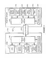
- FIG. 2is a simplified block diagram of a computer system according to an alternative embodiment of the present invention.
- FIG. 3is a simplified block diagram of a compeer system according to a further alternative embodiment of the present invention.
- FIG. 4is a simplified flow diagram of a method according to an embodiment of the present invention.
- FIG. 5is a block diagram of a computer system using a prior art interface between a primary and a secondary PCI bus.
- FIG. 6is a block diagram of one embodiment of a computer system using the interface of the present invention.
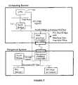
- FIG. 7is a partial block diagram of a computer system using the interface of the present invention as a bridge between the north and south bridges of the computer system.
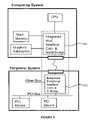
- FIG. 8is a partial block diagram of a computer system in which the north and south bridges are integrated with the host and peripheral interface controllers, respectively.
- FIG. 9is a block diagram of one embodiment of the host interface controller and the peripheral interface controller of the present invention.
- FIG. 10is a detailed block diagram of one embodiment of the host interface controller of the present invention.
- FIG. 11is a detailed block diagram of one embodiment of the PIC of the present invention.
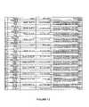
- FIG. 12is a table showing the symbols, signals, data rate and description of signals in a first embodiment of the XPBus.
- FIG. 13is a table showing the information transmitted on the XPBus during two clock cycles of the XPBus in one embodiment of the present invention where 10 data bits transmitted in each clock cycle of the XPBus.
- FIG. 14is a table showing information transmitted on the XPBus during four clock cycles of the XPBus in another embodiment of the present invention where 10 data bits are transmitted in each clock cycle of the XPBus.
- FIG. 15is a schematic diagram of the signal lines PCK, PD 0 to PD 3 , and PCN.
- FIG. 16is a table showing the names, types, number of pins dedicated to, and the description of the primary bus PCI signals.
- FIG. 17is a block diagram of one embodiment of a computer system employing the present invention.
- FIG. 18is a block diagram of an attached computing module (ACM).
- ACMattached computing module
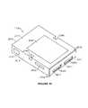
- FIG. 19illustrates an external view of one embodiment of an ACM.
- FIG. 19 billustrates one possible embodiment of a computer bay.
- FIG. 20illustrates the internal component layout for one embodiment of an ACM.
- FIG. 21is a block diagram of a peripheral console (PCON).
- FIG. 22is a simplified layout diagram of a security system for a computer system according to an embodiment of the present invention.
- FIG. 23is a simplified block diagram of a security system for a computer module according to an embodiment of the present invention.
- the present inventionprovides a system including a plurality of computer modules that can independently operate to provide backup capability, dual processing, and the like.
- FIG. 1is a simplified diagram of a computer system 100 according to an embodiment of the present invention.
- the computer system 100includes an attached computer module (i.e., ACM) 113 , a desktop console 101 , among other elements.
- the computer systemalso has another ACM module 117 .
- Each ACM modulehas a respective slot 121 , 119 , which mechanically houses and electrically couples each ACM to the computer console.
- a display 111which connects to the console.
- keyboard 109 and mouse 115are also shown.
- a second display 102 , keyboard 105 , and mouse 107can be coupled to the console in some optional embodiments to allow more than one user to operate the computer system.
- the computer systemis modular and has a variety of components that are removable. Some of these components (or modules) can be used in different computers, workstations, computerized television sets, and portable or laptop units.
- each ACM 113includes computer components, as will be described below, including a central processing unit (“CPU”), IDE controller, hard disk drive, computer memory, and the like.
- the computer module bay (i.e., CMB) 121is an opening or slot in the desktop console.
- the CMBhouses the ACM and provides communication to and from the ACM.
- the CMBalso provides mechanical protection and support to the ACM.
- the CMBhas a mechanical alignment mechanism for mating a portion of the ACM to the console.
- the CMBfurther has thermal heat dissipation sinks, electrical connection mechanisms, and the like.
- the present multiple computer module systemhas a peripheral console that has two or more computer bays that can receive a removable computer module or ACM.
- Multiple computer module systemcan function as a personal computer with only one ACM and the peripheral console.
- the second and additional ACMcan be added later to increase overall system performance and reliability.
- the ACMoperates independently as self-contained computer, communicates with each other through a high-speed serial communication and share most peripheral devices within the peripheral console.
- Each ACMcontrols its independent graphics subsystem and drives separate video output signals.
- a practical implementationis a dual ACM system. In a dual ACM system, two monitors can be used to display the two ACMs' graphics outputs at the same time.
- a RGB switchis used to switch between the video outputs of the two ACMs and can be controlled by a command from the user.
- input devicesi.e. keyboard and mouse
- Command from the usercan be in the form of either a dedicated key on the keyboard or a special icon on the screen that the mouse can click on.
- the ACMincludes an enclosure such as the one described with the following components, which should not be limiting:
- the ACMconnects to a peripheral console with power supply, a display device, an input device, and other elements. Some details of these elements with the present system are described in more detail below.
- the primary ACMcan connect directly to the peripheral board in the peripheral console.
- the second ACMcan connect either directly or indirectly to the peripheral board.
- a receptacle boardis added to allow a cable connection to the peripheral board. This is to facilitate the mechanical positioning of the second ACM inside the computer chassis.
- the receptacle board approachcan even be used for the primary ACM if a high bandwidth peripheral bus, e.g. PCI Bus, is not connected from the primary ACM to the peripheral board.
- the shared peripheral consolehas a chassis and a motherboard that connects the following devices:
- the computer bayis an opening in the peripheral console that receives an ACM.
- CMBprovides mechanical protection to ACM, mechanical alignment for connector mating, mechanical locking system to prevent theft and accidental removal, and connectors at the end of the opening for connecting to ACM.
- the interface bus between ACM and the peripheral consolehas a video bus, peripheral connections, serial communication connection, control signals and power connection.
- Video busincludes video output of graphics devices, i.e. analog RGB and control signals for monitor. Power connection supplies the power for ACM.
- peripheral sharingis the use of Ethernet controllers to bridge the communication between the two ACMs.
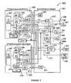
- Some of the peripheral devices residing in the peripheral consoleare shown in the simplified diagram of FIG. 2 . As shown, the diagram is merely an illustration which should not limit the scope of the claims herein. One of ordinary skill in the art would recognize many other variations, alternatives, and modifications.
- a primary ACM 203is connected to PCI peripheral devices in the peripheral console through the PCI bus 225 that passes through the connection between primary ACM 203 and peripheral console 201 .
- ACMhas a CPU module 207 coupled to the PCI bus through a North Bridge 211 .
- the CPU modulecan use a suitable microprocessing unit, microcontroller, digital signal processor, and the like.
- the CPU moduleuses, for example, a 400 MHz Pentium II microprocessor module from Intel Corporation and like microprocessors from AMD Corporation, Cyrix Corporation (now National Semiconductor Corporation), and others.
- the microprocessorcan be one such as the Compaq Computer Corporation Alpha Chip, Apple Computer Corporation PowerPC G3 processor, and the like. Further, higher speed processors are contemplated in other embodiments as technology increases in the future.
- peripheral controller 213is coupled to BIOS/flash memory 217 . Additionally, the peripheral controller is coupled to a clock control logic, a configuration signal, and a peripheral bus.
- the ACMhas the hard drive module 215 .
- the ACMincludes north bridge 215 , graphics subsystem 223 (e.g., graphics accelerator, graphics memory), an IDE controller, and other components. Adjacent to and in parallel alignment with the hard drive module 215 is the PCI bus.
- North Bridge unit 211often couples to a computer memory 209 , to the graphics subsystem, and to the peripheral controller via the PCI bus.
- Graphics subsystemtypically couples to a graphics memory, and other elements.
- IDE controllergenerally supports and provides timing signals necessary for the IDE bus.
- the IDE controlleris embodied as part of a P114XE controller from Intel, for example.
- Other types of buses than IDEare contemplated, for example EIDE, SCSI, 1394, and the like in alternative embodiments of the present invention.
- the hard drive module or mass storage unit 215typically includes a computer operating system, application software program files, data files, and the like.
- the computer operating systemmay be the Windows98 operating system from Microsoft Corporation of Redmond Washington.
- Other operating systemssuch as WindowsNT, MacOS8, Unix, and the like are also contemplated in alternative embodiments of the present invention.
- some typical application software programscan include Office98 by Microsoft Corporation, Corel Perfect Suite by Corel, and others.
- Hard disk module 215includes a hard disk drive.
- the hard disk drivecan also be replaced by removable hard disk drives, read/write CD ROMs, flash memory, floppy disk drives, and the like.
- a small form factor, for example 2.5′′,is currently contemplated, however, other form factors, such as PC card, and the like are also contemplated.
- Mass storage unit 240may also support other interfaces than IDE.
- the computer systemincludes an ACM with security protection.
- the ACMalso has a network controller, which can be an Ethernet controller 219 , which is coupled to the North Bridge through the PCI bus.
- the North Bridgeis coupled to the CPU.
- the Ethernet controllercan be a 10/100 Base, such as Intel's 82559 or the like. Other types of network connection devices can also be used.
- the inventioncan use Gbit Ethernet 1394, and USB 2.0.
- the network controllercouples to a hub 233 in the console, which includes shared peripheral system 201 .
- the second ACM 205has the same or similar components as the first ACM.
- like reference numeralshave been used for easy cross-referencing, but is not intended to be limiting.
- the secondary ACMis not connected to the PCI bus in the peripheral console directly.
- the secondary ACM 219accesses peripheral devices controlled by the primary ACM through the Ethernet connection to the primary ACM, e.g. CD-ROM, or PCI modem.
- the implementationis not restricted to Ethernet serial communication and can use other high-speed serial communication such as USB 2.0, and 1394.
- the Ethernet hubis coupled to an external output port 235 , which connects to an external network.
- the primary hard disk drive in each ACMcan be accessed by the other ACM as sharable hard drive through the Ethernet connection. This allows the easy sharing of files between the two independent computer modules.
- the Ethernet Hub Controllerprovides the high-speed communication function between the two computer modules. Ethernet data bandwidth of 100 Mbit/sec allows fast data communication between the two computer modules.
- the secondary ACMaccess peripheral devices of the primary ACM through the network connection provided by Ethernet link.
- the operating systeme.g. Windows 98, provides the sharing of resources between the two ACMs.
- critical data in one ACMcan be backup into the other ACM.
- the Ethernet hubalso couples to PCI bus 239 , which connects to PCI devices 241 , 243 , e.g., modem, SCSI controller.
- a flash memory 242can also be coupled to the PCI bus.
- the flash memorycan store passwords and security information, such as those implementations described in U.S. Ser. No. 09/183,493, which is commonly owned, and hereby incorporated by reference.
- the hub 233also couples to an I/O control 237 , which connects to keyboard/mouse switch 245 , which couples to keyboard/mouse 247 .
- the keyboard/mouse switchalso couples to a second keyboard/house 259 via PS2 or USB signal line 251 .
- the keyboard/mouse switchhas at least a first state and a second state, which allow operation of respectively multiple keyboards or a single keyboard.
- the switchalso couples to each I/O controller 221 in each ACM via lines 253 , 255 .
- the I/O control 237also couples to an RGB switch 257 , which allows video signals to pass to the first monitor 259 .
- the RGB switchcouples to a second monitor 261 .
- the RGB switchincludes analog video switches such as MAXIM's MAX4545.
- the peripheral system 201also has an independent power supply 231 for each ACM.
- Each power supplyprovides power to each ACM.
- the power supplyis a MICRO ATX 150 W made by ENLIGHT, but can be others.
- the power supplyis connected or coupled to each ACM through a separate line, for example.
- the independent power supplyallows for independent operation of each ACM in some embodiments.
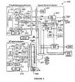
- FIG. 3is a simplified block diagram 300 of a computer system according to an alternative embodiment of the present invention.
- This diagramis merely an example which should not limit the scope of the claims herein.
- One of ordinary skill in the artwould recognizes many other variations, modifications, and alternatives.
- Like reference numeralsare used in this FIG. as the previous FIGS. for easy referencing, but are not intended to be limiting.
- each ACMincludes common elements as the previous FIG.
- a primary ACM 203is connected to PCI peripheral devices in the peripheral console through the PCI bus 225 that passes through the connection between primary ACM 203 and peripheral console 201 .
- ACMhas a CPU module 207 coupled to the PCI bus through a North Bridge 211 .
- the CPU modulecan use a suitable microprocessing unit, microcontroller, digital signal processor, and the like.
- the CPU moduleuses, for example, a 400 MHz Pentium II microprocessor module from Intel Corporation and like microprocessors from AMD Corporation, Cyrix Corporation (now National Semiconductor Corporation), and others.
- the microprocessorcan be one such as the Compaq Computer Corporation Alpha Chip, Apple Computer Corporation PowerPC G3 processor, and the like. Further, higher speed processors are contemplated in other embodiments as technology increases in the future.
- peripheral controller 213is coupled to BIOS/flash memory 217 . Additionally, the peripheral controller is coupled to a clock control logic, a configuration signal, and a peripheral bus.
- the ACMhas the hard drive module 215 .
- the ACMincludes north bridge 215 , graphics subsystem 223 (e.g., graphics accelerator, graphics memory), an IDE controller, and other components. Adjacent to and in parallel alignment with the hard drive module 215 is the PCI bus.
- North Bridge unit 211often couples to a computer memory 209 , to the graphics subsystem, and to the peripheral controller via the PCI bus.
- Graphics subsystemtypically couples to a graphics memory, and other elements.
- IDE controllergenerally supports and provides timing signals necessary for the IDE bus.
- the IDE controlleris embodied as part of a P114XE controller from Intel, for example.
- Other types of buses than IDEare contemplated, for example EIDE, SCSI, 1394, and the like in alternative embodiments of the present invention.
- the hard drive module or mass storage unit 215typically includes a computer operating system, application software program files, data files, and the like.
- the computer operating systemmay be the Windows98 operating system from Microsoft Corporation of Redmond Washington.
- Other operating systemssuch as WindowsNT, MacOS8, Unix, and the like are also contemplated in alternative embodiments of the present invention.
- some typical application software programscan include Office98 by Microsoft Corporation, Corel Perfect Suite by Corel, and others.
- Hard disk module 215includes a hard disk drive.
- the hard disk drivecan also be replaced by removable hard disk drives, read/write CD ROMs, flash memory, floppy disk drives, and the like.
- a small form factor, for example 2.5′′,is currently contemplated, however, other form factors, such as PC card, and the like are also contemplated.
- Mass storage unit 240may also support other interfaces than IDE.
- the computer systemincludes an ACM with security protection.
- the ACMalso has a network controller, which can be coupled to a serial port 302 , which is coupled to the PCI bus in the ACM.
- the serial portis coupled to the peripheral console through a serial controller 301 in the serial console.
- the serial controlleris connected to PCI bus 239 .
- the serial controlleris also coupled to a serial hub controller 303 , which is coupled to the PCI bus and a second ACM.
- a receptacle board 310is added to connect to the second ACM.
- the purpose of the receptacle boardis to allow a cable connection 307 to the peripheral board 300 .
- the cable connectionis possible because the signals needed to connect to the peripheral board can be limited to video, I/O, serial communication, and power.
- the serial communication controllercan be placed on the receptacle board and not in the ACM. As shown, the serial bus controller couples to the PCI bus. The receptacle board also couples to power, graphics subsystem, I/O controller, and other elements, which may be on a common bus. The overall operation of the present configuration is similar to the previous one except it operates in serial communication mode.
- the Dual ACM systemcan support different usage models:
- a video switch in the peripheral consoleis used to switch between the video outputs of the two ACMS.
- the systemcan be set to support either 1 monitor or 2-monitor mode.
- the userpresses a special key on the keyboard or a special icon on the screen to switch the screen display from one ACM to the other. This same action causes the keyboard and mouse connections to switch from one ACM to the other ACM.
- a dual ACM systemcan save space, wiring, and cost for a 2-person PC setup, with the added benefit that both PC systems can be accessed from one user site for increased system performance if the other user is not using the system.
- Filescan be copied between the primary drive of both system and provides protection against a single ACM failure.
- Softwareneeds to be developed to manage the concurrent use of two PC subsystems, the automatic sharing of selected files between the two systems, and fault tolerance.
- a peripheral consolehas four computer bays for four separate computer modules.
- the computer modulescommunicate through a four port Ethernet hub.
- the video, keyboard, and mouse switchwill cycle through the connection from each computer module to the external monitor, keyboard, and mouse with a push button sequentially.
- This embodimentis useful for a server that performs different functions concurrently, e.g. email, application hosting, web hosting, firewall, etc.
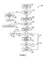
- FIG. 4is a simplified diagram of a method according to an embodiment of the present invention. This diagram is merely an example which should not limit the scope of the claims herein. One of ordinary skill in the art would recognize many other variations, modifications, and alternatives.
- the present diagramillustrates an automatic file backup procedure from one computer module to the other. As shown, a user selects (step 401 ) a certain file in one of the computer module for automatic backup. Next, the method determines if another module is available, step 403 . If so, the method in the originating module requests the other computer module to create (step 405 ) backup file. Alternatively, the method alerts the user of the missing or malfunctioning module, step 429 .
- the methodthen has the user try later 431 , once the missing or malfunctioning module has been replaced or repaired.
- the methoddetermines if there is sufficient storage available in the other computer module for the backup files. If so, the method goes to the next step. (Alternatively, the method prompts (step 433 ) a message to the user indicating that the storage is full.)
- the methodstores the backup file in memory of the other module.
- the software in the originating ACMsets a timer to check (step 411 ) for file modification via branches 423 , 427 through continue, step 425 process. If a file selected for backup has been modified (step 415 ), then the file is automatically back up to the other ACM again, step 417 . Alternatively, the method returns to step 411 through branch 421 .
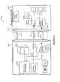
- FIG. 6is a block diagram of one embodiment of a computer system 600 using the interface of the present invention.
- Computer system 600includes an attached computer module (ACM) 605 and a peripheral console 610 , which are described in greater detail in the application of William W. Y. Chu for “Personal Computer Peripheral Console With Attached Computer Module” filed concurrently with the present application on Sep. 8, 1998 and incorporated herein by reference.
- the ACM 605 and the peripheral console 610are interfaced through an exchange interface system (XIS) bus 615 .
- the XIS bus 615includes power bus 616 , video bus 617 and peripheral bus (XPBus) 618 , which is also herein referred to as an interface channel.
- XISexchange interface system
- XPBusperipheral bus
- the power bus 616transmits power between ACM 605 and peripheral console 610 .
- power bus 616transmits power at voltage levels of 3.3 volts, 5 volts and 12 volts.
- Video bus 617transmits video signals between the ACM 605 and the peripheral console 610 .
- the video bus 617transmits analog Red Green Blue (RGB) video signals for color monitors, digital video signals (such as Video Electronics Standards Association (VESA) Plug and Display's Transition Minimized Differential Signaling (TMDS) signals for flat panel displays), and television (TV) and/or super video (S-video) signals.
- the XPBus 618is coupled to host interface controller (HIC) 619 and to peripheral interface controller (PIC) 620 , which is also sometimes referred to as a bay interface controller.
- HIChost interface controller
- PICperipheral interface controller
- HIC 619is coupled to an integrated unit 621 that includes a CPU, a cache and a north bridge.
- the CPU 705 and north bridge 710are separate rather than integrated units.
- the HIC and PICare integrated with the north and south bridges, respectively, such that integrated HIC and north bridge unit 805 includes an HIC and a north bridge, while integrated PIC and south bridge unit 810 includes a PIC and a south bridge.
- FIG. 9is a more detailed block diagram of one embodiment of an HIC 905 and a PIC 955 of the present invention.
- HIC 905includes a peripheral component interconnect (PCI) bus controller 910 , an XPBus controller 915 , a phase lock loop (PLL) clock 920 and an input/output ( 10 ) control 925 .
- PIC 955includes a PCI bus controller 960 , an XPBus controller 965 , a PLL clock 970 and an IO control 975 .
- PCI bus controllers 910 and 960are coupled to the primary and secondary PCI buses 930 and 980 , respectively, and manage PCI transactions on the primary and secondary PCI buses 930 and 980 , respectively.
- XPBus Controllers 915 and 965are coupled to XPBus 990 .
- XPBus controller 915drives the PCK line 991 and PD[0::3] and PCN lines 992 while XPBus controller 965 drives the PCKR lines 993 , the PDR[0::3] and PCNR lines 994 and the RESET# line 995 .
- PCI bus controller 910receives PCI clock signals from the primary PCI bus 930 and is synchronized to the PCI clock. However, as indicated in FIG. 9 , the XPBus controller 915 is asynchronous with the PCI bus controller 910 . Instead, the XPBus controller receives a clock signal from the PLL clock 920 and is synchronized therewith. PLL clock 920 generates a clock signal independent of the PCI clock. The asynchronous operation of the PCI bus and the XPBus allows the PCI Bus to change in frequency, for example as in a power down situation, without directly affecting the XPBus clocking. In the embodiment shown in FIG.
- the PLL clock 920generates a clock signal having a frequency of 66 MHz, which is twice as large as the 33 MHz frequency of the PCI clock.
- the clock signal generated by the PLL clockmay have a clock speed different from, including lower than, 66 MHz.
- the PLL clock 920generates a clock signal having a frequency of 132 MHz.
- the XPBus 990operates at the clock speed generated by the PLL clock 920 . Therefore, PCK, the clock signal from the XPBus controller 915 to XPBus controller 965 has the same frequency as the clock signal generated by PLL clock 920 .
- XPBus controller 965receives the PCK signal after it has been buffered and operates at the clock speed of PCK.
- the buffered version of the clock signal PCKis used to generate the clock signal PCKR, the clock signal form the XPBus controller 965 to XPBus controller 915 . Accordingly, PCKR also has the same frequency as that generated by the PLL clock 920 .
- the synchronous operation of PCK and PCKRprovides for improved reliability in the system.
- PCKRmay be generated independently of PCK and may have a frequency different from that of PCK. It is to be noted that even when PCKR is generated from PCK, the slew between PCK and PCKR cannot be guaranteed because of the unknown cable length used for the XPBus. For a cable that is several feet long, the cable propagation delay alone can be several nano seconds.
- PLL clock 970is asynchronous with the XPBus controller 965 . Instead, PLL clock 970 independently generates a clock signal that is used as a PCI clock signal on the secondary PCI bus 980 .
- the secondary PCI bus 980operates at the same clock speed as the primary PCI bus 930 , namely at a frequency of 33 MHz.
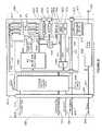
- FIG. 10is a detailed block diagram of one embodiment of the HIC of the present invention.
- HIC 1000comprises bus controller 1010 , translator 1020 , transmitter 1030 , receiver 1040 , a PLL 1050 , an address/data multiplexer (A/D MUX) 1060 , a read/write controller (RD/WR Cntl) 1070 , a video serial to parallel converter 1080 and a CPU control & general purpose input/output latch/driver (CPU CNTL & GPIO latch/driver) 1090 .
- A/D MUXaddress/data multiplexer
- RD/WR Cntlread/write controller
- video serial to parallel converter 1080and a CPU control & general purpose input/output latch/driver (CPU CNTL & GPIO latch/driver) 1090 .
- CPU CNTL & GPIO latch/driverCPU control & general purpose input/output latch/driver
- Flash memory unit 1001stores basic input output system (BIOS) and PCI configuration information and supplies the BIOS and PCI configuration information to A/D MUX 1060 and RD/WR Control 1070 , which control the programming, read, and write of flash memory unit 1001 .
- BIOSbasic input output system
- A/D MUX 1060 and RD/WR Control 1070which control the programming, read, and write of flash memory unit 1001 .
- Bus controller 1010is coupled to the host PCI bus, which is also referred to herein as the primary PCI bus, and manages PCI bus transactions on the host PCI bus.
- Bus controller 1010includes a slave (target) unit 1011 and a master unit 1016 .
- Both slave unit 1011 and master unit 1016each include two first in first out (FIFO) buffers, which are preferably asynchronous with respect to each other since the input and output of the two FIFOs in the master unit 1016 as well as the two FIFOs in the slave unit 1011 are clocked by different clocks, namely the PCI clock and the PCK.
- slave unit 1011includes encoder 1022 and decoder 1023
- master unit 1016includes encoder 1027 and decoder 1028 .
- the FIFOs 1012 , 1013 , 1017 and 1018manage data transfers between the host PCI bus and the XPBus, which in the embodiment shown in FIG. 10 operate at 33 MHz and 106 MHz, respectively.
- PCI address/data (AD) from the host PCI busis entered into FIFOs 1012 and 1017 before they are encoded by encoders 1022 and 1023 .
- Encoders 1022 and 1023format the PCI address/data bits to a form more suitable for parallel to serial conversion prior to transmittal on the XPBus.
- address and data information from the receiversis decoded by decoders 1023 and 1028 to a form more suitable for transmission on the host PCI bus.
- FIFOs 1013 and 1018Thereafter the decoded data and address information is passed through FIFOs 1013 and 1018 prior to being transferred to the host PCI bus.
- FIFOs 1012 , 1013 , 1017 and 1018allow bus controller 1010 to handle posted and delayed PCI transactions and to provide deep buffering to store PCI transactions.
- Bus controller 1010also comprises slave read/write control (RD/WR Cntl) 1014 and master read/write control (RD/WR Cntl) 1015 .
- RD/WR controls 1014 and 1015are involved in the transfer of PCI control signals between bus controller 1010 and the host PCI bus.
- Bus controller 1010is coupled to translator 1020 .
- Translator 1020comprises encoders 1022 and 1027 , decoders 1023 and 1028 , control decoder & separate data path unit 1024 and control encoder & merge data path unit 1025 .
- encoders 1022 and 1027are part of slave data unit 1011 and master data unit 1016 , respectively, receive PCI address and data information from FIFOs 1012 and 1017 , respectively, and encode the PCI address and data information into a form more suitable for parallel to serial conversion prior to transmittal on the XPBus.
- decoders 1023 and 1028are part of slave data unit 1011 and master data unit 1016 , respectively, and format address and data information from receiver 1040 into a form more suitable for transmission on the host PCI bus.
- Control encoder & merge data path unit 1025receives PCI control signals from the slave RD/WR control 1014 and master RD/WR control 1015 . Additionally, control encoder & merge data path unit 1025 receives control signals from CPU CNTL & GPIO latch/driver 1090 , which is coupled to the CPU and north bridge (not shown in FIG. 10 ).
- Control encoder & merge data path unit 1025encodes PCI control signals as well as CPU control signals and north bridge signals into control bits, merges these encoded control bits and transmits the merged control bits to transmitter 1030 , which then transmits the control bits on the data lines PD 0 to PD 3 and control line PCN of the XPBus.
- Examples of control signalsinclude PCI control signals and CPU control signals.
- a specific example of a control signalis FRAME# used in PCI buses.
- a control biton the other hand is a data bit that represents a control signal.
- Control decoder & separate data path unit 1024receives control bits from receiver 1040 which receives control bits on data lines PDR 0 to PDR 3 and control line PCNR of the XPBus.
- Control decoder & separate data path unit 1024separates the control bits it receives from receiver 1040 into PCI control signals, CPU control signals and north bridge signals, and decodes the control bits into PCI control signals, CPU control signals, and north bridge signals all of which meet the relevant timing constraints.
- Transmitter 1030receives multiplexed parallel address/data (A/D) bits and control bits from translator 1020 on the AD[31::0] out and the CNTL out lines, respectively. Transmitter 1030 also receives a clock signal from PLL 1050 . PLL 1050 takes a reference input clock and generates PCK that drives the XPBus. PCK is asynchronous with the PCI clock signal and operates at 106 MHz, twice the speed of the PCI clock of 33 MHz. The higher speed is intended to accommodate at least some possible increases in the operating speed of future PCI buses. As a result of the higher speed, the XPBus may be used to interface two PCI or PCI-like buses operating at 106 MHz rather than 33 MHz or having 104 rather than 32 multiplexed address/data lines.
- the multiplexed parallel A/D bits and some control bits input to transmitter 1030are serialized by parallel to serial converters 1032 of transmitter 1030 into 10 bit packets. These bit packets are then output on data lines PD 0 to PD 3 of the XPBus. Other control bits are serialized by parallel to serial converter 1033 into 10 bit packets and send out on control line PCN of the XPBus.
- a 10 ⁇ multiplier 1031receives PCK, multiplies it by a factor of 10 and feeds a clock signal 10 times greater than PCK into the parallel to serial converters 1032 and 1033 .
- the parallel to serial converters 1032 and 1033perform bit shifting at 10 times the PCK rate to serialize the parallel bits into 10 bit packets.
- the bit rate for the serial bits output by the parallel to serial convertersis 10 times higher than PCK rate, i.e., 1060 MHz.
- the rate at which data packets are transmitted on the XPBusis the same as the PCK rate, i.e., 106 MHz.
- the PCI busesoperate at a clock and bit rate of 33 MHz
- the XPBushas a clock rate that is twice as large and a bit rate per bit line (channel) that is 100 times as large as that of the PCI buses which it interfaces.
- Receiver 1040receives serial bit packets on data lines PDR 0 to PDR 3 and control line PCNR. Receiver 1040 also receives PCKR on the XPBus as well as the clock signal PCK from PLL 1050 .
- the synchronizer (SYNC) 1044 of receiver 1040synchronizes the clock signal PCKR to the locally generated clock signal, PCK, in order to capture the bits received from the XPBus into PCK clock timing.
- Serial to parallel converters 1042convert the serial bit packets received on lines PDR 0 to PDR 3 into parallel address/data and control bits that are sent to decoders 1023 and 1028 and control decoder and separate data path unit 1024 , respectively.
- Serial to parallel converter 1043receives control bit packets from control line PCNR, converts them to parallel control bits and sends the parallel control bits to control decoder & separate data path 1024 .
- a 10 ⁇ multiplier 1041receives PCKR, multiplies it by a factor of 10 and feeds a clock signal 10 times greater than PCKR into the serial to parallel converters 1042 and 1043 . Because the bits on PDR 0 to PDR 3 and PCNR are transmitted at a bit rate of 10 times the PCKR rate, the serial to parallel converters 1042 and 1043 perform bit shifting at 10 times the PCKR rate to convert the 10 bit packets into parallel bits. It is to be noted that the rate at which bit packets are transmitted on the XPBus is the same as the PCKR rate, i.e., 106 MHz.
- the parallel data and control bitsare thereafter sent to decoders 1023 and 1028 by way of the AD[3::0] in line and to control decoder & separate data path unit 1024 by way of CNTL in lines, respectively.
- Reset control unit 1045 of HIC 1000receives the signal RESET#, which is an independent system reset signal, on the reset line RESET#. Reset control unit 1045 then transmits the reset signal to the CPU CNTL & GPIO latch/driver unit 1090 .
- the 32 line host and secondary PCI busesare interfaced by 10 XPBus lines (PD 0 , PD 1 , PD 2 , PD 3 , PCN, PDR 0 , PDR 1 , PDR 2 , PDR 3 , PCNR). Therefore, the interface channel, XPBus, of the present invention uses fewer lines than are contained in either of the buses which it interfaces, namely the PCI buses. XPBus is able to interface such PCI buses without backup delays because the XPBus operates at a clock rate and a per line (channel) bit rate that are higher than those of the PCI buses.
- the CPU CNTL & GPIO latch/driver 1090is responsible for latching input signals from the CPU and north bridge and sending the signals to the translator. It also takes decoded signals from the control decoder & separate data path unit 1024 and drives the appropriate signals for the CPU and north bridge.
- video serial to parallel converter 1080is included in HIC 1000 .
- video serial to parallel converter 1080may be a separate unit from the HIC 1000 .
- Video serial to parallel converter 1080receives serial video data on line VPD and a video clock signal VPCK from line VPCK of video bus 1081 . It then converts the serial video data into 16 bit parallel video port data and the appropriate video port control signals, which it transmits to the graphics controller (not shown in FIG. 10 ) on the video port data [0::15] and video port control lines, respectively.
- HIC 1000handles the PCI bus control signals and control bits from the XPBus representing PCI control signals in the following ways:
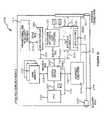
- FIG. 11is a detailed block diagram of one embodiment of the PIC of the present invention.
- PIC 1100is nearly identical to HIC 1000 in its function, except that HIC 1000 interfaces the host PCI bus to the XPBus while PIC 1100 interfaces the secondary PCI bus to the XPBus.
- the components in PIC 1100serve the same function as their corresponding components in HIC 1000 .
- Reference numbers for components in PIC 1100have been selected such that a component in PIC 1100 and its corresponding component in HIC 1000 have reference numbers that differ by 500 and have the same two least significant digits.
- the bus controller in PIC 1100is referenced as bus controller 1110 while the bus controller in HIC 1000 is referenced as bus controller 1010 .
- HIC 1000 and PIC 1100there are also differences between HIC 1000 and PIC 1100 .
- Some of the differences between HIC 1000 and PIC 1100include the following.
- receiver 1140 in PIC 1100unlike receiver 1040 in HIC 1000 , does not contain a synchronization unit.
- the synchronization unit in HIC 1000synchronizes the PCKR clock to the PCK clock locally generated by PLL 1050 .
- PIC 1100does not locally generate a PCK clock and therefore, it does not have a locally generated PCK clock with which to synchronize the PCK clock signal that it receives from HIC 1000 .
- PIC 1100contains a video parallel to serial converter 189 whereas HIC 1000 contains a video serial to parallel converter 1080 .
- Video parallel to serial converter 1189receives 16 bit parallel video capture data and video control signals on the Video Port Data [0::15] and Video Port Control lines, respectively, from the video capture circuit (not shown in FIG. 11 ) and converts them to a serial video data stream that is transmitted on the VPD line to the HIC.
- the video capture circuitmay be any type of video capture circuit that outputs a 16 bit parallel video capture data and video control signals.
- PIC 1100unlike HIC 1000 , contains a clock doubler 1182 to double the video clock rate of the video clock signal that it receives.
- the doubled video clock rateis fed into video parallel to serial converter 1182 through buffer 1183 and is sent to serial to parallel converter 1080 through buffer 1184 .
- reset control unit 1135 in PIC 1100receives a reset signal from the CPU CNTL & GPIO latch/driver unit 1190 and transmits the reset signal on the RESET# line to the HIC 1000 whereas reset control unit 1045 of HIC 1000 receives the reset signal and forwards it to its CPU CNTL & GPIO latch/driver unit 1090 because, in the above embodiment, the reset signal RESET# is unidirectionally sent from the PIC 1100 to the HIC 1000 .
- PIC 1100handles the PCI bus control signals and control bits from the XPBus representing PCI control signals in the following ways:
- PIC 1100also supports a reference arbiter on the secondary PCI Bus to manage the PCI signals REQ# and GNT#.
- FIG. 12is a table showing the symbols, signals, data rate and description of signals on the XPBus, where RTN indicates a ground (GND) reference.
- P&Dstands for plug and display and is a trademark of the Video Electronics Standards Association (VESA) for the Plug and Display standard
- DDC2:SCL and DDC2:SDAstand for the VESA display data channel (DDC) standard 2 clock and data signals, respectively
- SVstands for super video
- V 33is 3.3 volts
- V 5is 5.0 volts.
- TMDSstands for Transition Minimized Differential Signaling and is a trademark of Silicon Images and refers to their Panel Link technology, which is in turn a trademark for their LVDS technology.
- TMDSis used herein to refer to the Panel Link technology or technologies compatible therewith.
- FIG. 13is a table showing the information transmitted on the XPBus during two clock cycles of the XPBus in one embodiment of the present invention where 10 data bits are transmitted in each clock cycle of the XPBus.
- a 00 to A 31represent 32 bits of PCI address A[31::0]
- D 00 to D 31represent 32 bits of PCI data D[31::0]
- BS 0 to BS 3represent 4 bits of bus status data indicating the status of the XPBus
- CM 0 # to CM 3 #represent 4 bits of PCI command information
- BE 0 # to BE 3 #represent 4 bits of PCI byte enable information
- CN 0 to CN 9represent 10 bits of control information sent in each clock cycle.
- D 00 to D 31represent 32 bits of PCI data D[31::0]
- BS 0 to BS 3represent 4 bits of bus status data indicating the status of
- the 10 bit data packetscontain one BS bit, one CM/BE bit, and eight A/D bits.
- the 10 bit data packetcontains 10 CN bits.
- the first clock cycle shown in FIG. 13comprises an address cycle in which 4 BS bits, 4 CM bits, 32 A bits and 10 CN bits are sent.
- the second clock cyclecomprises a data cycle in which 4 BS bits, 4 BE bits, 32 D bits and 10 CN bits are sent.
- the bits transmitted on lines PD 0 to PD 3represent 32 PCI AD[31::0] signals, 4 PCI C/BE# [3::0] signals, and part of the function of PCI control signals, such as FRAME#, IRDY#, and TRDY#.
- BS 0 to BS 3are sent at the beginning of each clock cycle.
- the bus status bitsindicate the following bus cycle transactions: idle, address transfer, write data transfer, read data transfer, switch XPBus direction, last data transfer, wait, and other cycles.
- Bits representing signals transmitted between the CPU and South Bridgemay also be sent on the lines interconnecting the HIC and PIC, such as lines PCN and PCNR.
- CPU interface signalssuch as CPU interrupt (INTR), Address 20 Mask (A 20 M#), Non-Maskable Interrupt (NMI), System Management Interrupt (SMI#), and Stop Clock (STPCLK#), may be translated into bit information and transmitted on the XPBus between the HIC and the PIC.
- FIG. 14is a table showing the information transmitted on the XPBus during four clock cycles of the XPBus in another embodiment of the present invention where 10 data bits are transmitted in each clock cycle of the XPBus.
- the XPBus clock rateis twice as large as the PCI clock rate. This allows sending data and address bits every other XPBus cycle. As can be seen in FIG. 14 , there are no address or data bits transmitted during the second or fourth XPBus clock cycle.
- the fact that the XPBus clock rate is higher than the PCI clock rateallows for compatibility of the XPBus with possible future expansions in the performance of PCI bus to higher data transfer and clock rates.
- control bitsthere are 18 control bits, CN 0 to CN 17 , transmitted in every two XPBus clock cycles.
- the first bit transmitted on the control line in each XPBus clock cycleindicates whether control bits CN 0 to CN 8 or control bits CN 9 to CN 17 will be transmitted in that cycle.
- a zero sent at the beginning of a cycle on the control lineindicates that CN 0 to CN 8 will be transmitted during that cycle, whereas a one sent at the beginning of a cycle on the control line indicates that CN 9 to CN 17 will be transmitted during that cycle.
- These bitsalso indicate the presence or absence of data and address bits during that cycle. A zero indicates that address or data bits will be transmitted during that cycle whereas a one indicates that no address or data bits will be transmitted during that cycle.
- BS 0 and BS 1are used to encode the PCI signals FRAME# and IRDY#, respectively.
- BS 2 and BS 3are used to indicate the clock speed of the computer bus interface and the type of computer bus interface, respectively. For example, BS 2 value of zero may indicate that a 33 MHz PCI bus of 32 bits is used whereas a BS 2 value of one may indicate that a 66 MHz PCI bus of 32 bits is used.
- a BS 3 value of zeromay indicated that a PCI bus is used whereas a BS 3 value of one may indicated that another computer interface bus, such as an Institute of Electronics & Electrical Engineers (IEEE) 1394 bus, is used.
- IEEE 1394Institute of Electronics & Electrical Engineers
- FIG. 15is a schematic diagram of lines PCK, PD 0 to PD 3 , and PCN. These lines are unidirectional LVDS lines for transmitting clock signals and bits such as those shown in FIGS. 13 and 14 from the HIC to the PIC. The bits on the PD 0 to PD 3 and the PCN lines are sent synchronously within every clock cycle of the PCK. Another set of lines, namely PCKR, PDR 0 to PDR 3 , and PCNR, are used to transmit clock signals and bits from the PIC to HIC. The lines used for transmitting information from the PIC to the HIC have the same stricture as those shown in FIG. 15 , except that they transmit data in a direction opposite to that in which the lines shown in FIG. 15 transmit data.
- control informationthat may be sent in the reverse direction, i.e., on PCNR line, include a request to switch data bus direction because of a pending operation (such as read data available), a control signal change in the target requiring communication in the reverse direction, target busy, and transmission error detected.
- the XPBuswhich includes lines PCK, PD 0 to PD 3 , PCN, PCKR, PDR 0 to PDR 3 , and PCNR, has two sets of unidirectional lines transmitting clock signals and bits in opposite directions.
- the first set of unidirectional linesincludes PCK, PD 0 to PD 3 , and PCN.
- the second set of unidirectional linesincludes PCKR, PDR 0 to PDR 3 , and PCNR.
- Each of these unidirectional set of linesis a point-to-point bus with a fixed transmitter and receiver, or in other words a fixed master and slave bus.
- the HICis a fixed transmitter/master whereas the PIC is a fixed receiver/slave.
- the PICis a fixed transmitter/master whereas the HIC is a fixed receiver/slave.
- the LVDS lines of XPBusa cable friendly and remote system I/O bus, transmit fixed length data packets within a clock cycle.
- the XPBus lines, PD 0 to PD 3 , PCN, PDR 0 to PDR 3 and PCNR, and the video data and clock lines, VPD and VPCK,are not limited to being LVDS lines, as they may be other forms of bit based lines.
- the XPBus linesmay be IEEE 1394 lines.
- each of the lines PCK, PD 0 to PD 3 , PCN, PCKR, PDR 0 to PDR 3 , PCNR, VPCK, and VPDis referred to as a line, in the singular rather than plural, each such line may contain more than one physical line.
- each of lines PCK, PD 0 to PD 3 and PCNincludes two physical lines between each driver and its corresponding receiver.
- the term linewhen not directly preceded by the terms physical or conductive, is herein used interchangeably with a signal or bit channel which may consist of one or more physical lines for transmitting a signal.
- a signal or bit channelwhich may consist of one or more physical lines for transmitting a signal.
- a pair of physical linesis used to transmit one signal.
- a bit line or bit channel in an LVDS or IEEE 1394 interfaceconsists of a pair of physical lines which together transmit a signal.
- a bit based line(i.e., a bit line) is a line for transmitting serial bits.
- Bit based linestypically transmit bit packets and use a serial data packet protocol. Examples of bit lines include an LVDS line, an IEEE 1394 line, and a Universal Serial Bus (USB) line.
- FIG. 16is a table showing the names, types, number of pins dedicated to, and the description of the primary bus PCI signals.
- the pinsrepresent those between the host PCI bus and the HIC.
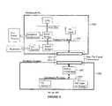
- FIG. 17is a block diagram of the components in one computer system employing the present invention.
- the computer systemcomprises an attached computer module (ACM), a peripheral console (PCON), and the interconnection apparatus between them.
- the ACMincludes the central processing unit (CPU) 1710 , system memory 1720 , high performance devices 1750 , primary mass storage 1730 , and related interface and support circuitry 1740 .
- the PCONincludes primary display 1810 , primary input 1820 , secondary mass storage 1750 , other devices 1860 , expansion slots 1870 , the primary power supply 1830 , and related interface and support circuitry 1840 .
- the interconnection apparatus 1900includes circuitry to convey power and operational signals between the ACM and PCON.
- the CPU 1710executes instructions and manipulates data stored in the system memory.
- the CPU 1710 and system memory 1720represent the user's core computing power.
- the core computing powermay also include high performance devices 1750 such as advanced graphics processor chips that greatly increase overall system performance and which, because of their speed, need to be located close to the CPU.
- the primary mass storage 1730contains persistent copies of the operating system software, application software, configuration data, and user data.
- the software and data stored in the primary mass storage devicerepresent the user's computing environment.
- Interface and support circuitry 1740primarily includes interface chips and signal busses that interconnect the CPU, system memory, high performance devices, and primary mass storage.
- the interface and support circuitryalso connects ACM-resident components with the ACM-to-PCON interconnection apparatus as needed.
- the primary display component 1810may include an integrated display device or connection circuitry for an external display device.
- This primary display devicemay be, for example, an LCD, plasma, or CRT display screen used to display text and graphics to the user for interaction with the operating system and application software.
- the primary display componentis the primary output of the computer system, i.e., the paramount vehicle by which programs executing on the CPU can communicate toward the user.
- the primary input component 1820 of the PCONmay include an integrated input device or connection circuitry for attachment to an external input device.
- the primary inputmay be, for example, a keyboard, touch screen, keypad, mouse, trackball, digitizing pad, or some combination thereof to enable the user to interact with the operating system and application software.
- the primary input componentis the paramount vehicle by which programs executing on the CPU receive signals from the user.
- the PCONmay contain secondary mass storage 1850 to provide additional high capacity storage for data and software.
- Secondary mass storagemay have fixed or removable media and may include, for example, devices such as diskette drives, hard disks, CD-ROM drives, DVD drives, and tape drives.
- the PCONmay be enhanced with additional capability through the use of integrated “Other Devices” 1860 or add-on cards inserted into the PCON's expansion slots 1870 .
- additional capabilityinclude sound generators, LAN connections, and modems.
- Interface and support circuitry 1840primarily includes interface chips, driver chips, and signal busses that interconnect the other components within the PCON. The interface and support circuitry also connects PCON-resident components with the ACM-to-PCON interconnection apparatus as needed.
- the PCONhouses the primary power supply 1830 .
- the primary power supplyhas sufficient capacity to power both the PCON and the ACM 1700 for normal operation.
- the ACMmay include a secondary “power supply” in the form, for example, of a small battery.
- a secondary “power supply”would be included in the ACM to maintain, for example, a time-of-day clock, configuration settings when the ACM is not attached to a PCON, or machine state when moving an active ACM immediately from one PCON to another.
- the total energy stored in such a batterywould, however, be insufficient to sustain operation of the CPU at its rated speed, along with the memory and primary mass storage, for more than a fraction of an hour, if the battery were able to deliver the required level of electrical current at all.
- FIG. 18is a block diagram of an attached computing module (ACM) 1700 .
- the physical ACM package 1700contains the ACM functional components 1701 and the ACM side of the ACM-to-PCON Interconnection 1900 .
- the ACM 1701comprises a CPU component 1710 , a system memory component 1720 , a primary mass storage component 1730 , a high performance devices components 1750 , and an interface and support component 1740 .
- the ACM side of the ACM-to-PCON Interconnection 1900comprises a Host Interface Controller (HIC) component 1920 and an ACM connector component 1930 .
- the HIC 1920 and connector 1930 componentscouple the ACM functional components 1700 with the signals of an ACM-to-PCON interface bus 1910 used to operatively connect an ACM with a PCON.
- the ACM-to-PCON interface bus 1910comprises conveyance for electrical power 1914 and signals for a peripheral bus 1912 , video 1916 , video port 1917 , and console type 1918 .
- the preferred ACM-to-PCON Interconnection 1900is described in detail in a companion U.S. patent application, Ser. No.
- the preferred ACM-to-PCON interconnection 1900includes circuitry to transmit and receive parallel bus information from multiple signal paths as a serial bit stream on a single signal path. This reduces the number of physical signal paths required to traverse the interconnection 1900 . Further, employing low-voltage differential signaling (LVDS) on the bit stream data paths provides very reliable, high-speed transmission across cables. This represents a further advantage of the present invention.
- LVDSlow-voltage differential signaling
- the CPU component 1710 of the ACM functional circuitry 1701 of the presently described embodimentcomprises a microprocessor 1712 , which is the chief component of the personal computer system, power supply connection point 1713 , and cache memory 1714 tightly coupled to the microprocessor 1712 by the CPU-to-cache bus 1714 comprising signal paths for address, data, and control information.
- the microprocessor 1712 of this embodimentis one of the models from the Pentium II family of processors from Intel Corporation.
- Microprocessor 1712receives electrical power from power bus 1768 via connection point 1713 .
- Microprocessor 1712couples to the Host Interface Controller (HIC) 1920 via CPU-to-HIC bus 1763 comprising signal paths to exchange control information such as an interrupt request.
- Microprocessor 1712also couples to CPU Bridge 1746 via CPU main bus 1764 comprising signal paths for address, data, and control information.
- HICHost Interface Controller
- the CPU Bridge component 1746 of the interface and support circuitry 1740operates to couple the high speed CPU main bus 1764 to specialty buses of varying speeds and capability that connect other computer components.
- the CPU Bridge of the presently described embodimentincorporates memory controller circuitry, advanced graphics processor support circuitry, and a general, industry-standard PCI bus controller in a single package.
- a CPU Bridge 1746such as the 82443LX PCI/AGP Controller from Intel Corporation may be used.
- the system memory component 1720 of the ACM functional circuitry 1701 in the present embodimentcomprises main system memory (RAM) 1722 , BIOS memory 1724 , and flash memory 1726 .
- the system memory 1720is used to contain data and instructions that are directly addressable by the CPU.
- the RAM 1722comprises volatile memory devices such as DRAM or SDRAM memory chips that do not retain their stored contents when power is removed. This form of memory represents the largest proportion of total system memory 1720 capacity.
- the BIOS memory 1724comprises non-volatile memory devices such as ROM or EPROM memory chips that retain their stored contents regardless of the application of power and are read-only memory under normal operating conditions.
- the BIOS memory 1724stores, for example, start-up instructions for the microprocessor 1712 and sets of instructions for rudimentary input/output tasks.
- the flash memory 1726comprises non-volatile memory devices that retain their stored contents regardless of the application of power. Unlike the BIOS non-volatile memory, however, the stored contents of the flash memory 1726 are easily changed under normal operating conditions.
- the flash memory 1726may be used to store status and configuration data, such as security identifiers or ACM specifications like the speed of the microprocessor 1712 . Some embodiments may combine the BIOS functions into the flash memory device, thus permitting BIOS contents to be rewritten, improving field upgradability.
- the main system memory (RAM) 1722is coupled to memory controller circuitry resident within the CPU Bridge 1746 via direct memory bus 1765 .
- the BIOS 1724 and flash memory 1726are coupled to HIC 1920 via switched memory bus 1766 . This permits the BIOS 1724 and flash 1726 memories to be accessed by circuitry in the HIC 1920 or other circuitry connected thereto.
- the direct memory bus 1765 and the switch memory bus 1766each comprises conductors to convey signals for data, address, and control information.
- the primary mass storage component 1730 of the ACM functional circuitry 1701 in the present embodimentcomprises a compact hard disk drive with an industry-standard, IDE interface.
- the hard disk drive (HDD) 1732has a formatted storage capacity sufficient to contain an operating system for the computer, application software desired by the user, and related user configuration and operating parameter data.
- the HDD 1732 in the present embodimentserves as the “boot” device for the personal computer from which the operating system is loaded into RAM 1722 by the start-up program stored in the BIOS 1724 .
- the present HDD 1732has a capacity of approximately 2,000 megabytes to provide adequate storage for common software configurations and reasonable space for user data.
- a common software configurationincludes the Windows 95 operating system from Microsoft Corporation, a word processing program, a spreadsheet program, a presentation graphics program, a database program, an email program, and a web browser such as Navigator from Netscape Corporation.
- the hard disk 1732stores program and data files for each software component, including files distributed by the vendor as well as files created or updated by operation of the software after it is installed.
- a word processor programmay maintain information about a user's identity and latest preferences in an operating system registry file.
- the web browsermay maintain a file of the user's favorite web sites or most recently viewed web pages.
- An HDD with 2000 megabyte capacityis readily available in the small size of hard disk (e.g., 2.5-inch or 3.5-inch) to minimize the space required within the ACM for the primary mass storage device 1730 .
- the HDD 1732is coupled to IDE controller circuitry 1748 via IDE bus 1772 .
- the IDE controller circuitry 1748is coupled to the CPU Bridge 1746 via the Host PCI bus 1767 .
- IDE controllers and busses, and the PCI busare well known and understood in the industry. The above components operate together to couple the hard disk drive 1732 to the microprocessor 1712 .
- the high performance devices component 1750 of the ACM functional circuitry 1701 in the present embodimentcomprises an Advanced Graphics Processor (AGP) 1752 .
- AGPAdvanced Graphics Processor
- the Model 740 Graphics Device from Intel Corporationmay be used in the present embodiment as the AGP.
- the AGP 1752is located in the ACM 1700 , where it is in close proximity to the microprocessor 1712 .
- the AGP 1752is coupled to the microprocessor 1712 via the advanced graphics port bus 1773 of the CPU Bridge 1746 .
- the visual display signal generated by the AGPare conveyed toward actual display devices at the peripheral console (PCON) via video signal bus 1770 .
- Video information from a source external to the ACM and appearing as video port signals 1917may be conveyed to the AGP 1752 via video port signal path 1771 .
- high performance componentsmay be included in different ACM configurations.
- an interface to an extremely high speed data communication facilitymay be desirable in some future computer where CPU-to-network interaction is of comparable intensity to today's CPU-to-graphics interaction.
- CPU-to-network interactionis of comparable intensity to today's CPU-to-graphics interaction.
- high performance componentstend to be high in cost, their inclusion in the ACM is desirable.
- Inclusion of high cost, high performance components in the ACMconcentrates a user's core computing power and environment in a portable package. This represents a further advantage of the invention.
- the interface and support component 1740 of the ACM functional circuitry 1701 in the present embodimentcomprises circuitry for power regulation 1742 , clocking 1744 , CPU Bridge 1746 , IDE controller 1748 , and signal conveyance paths 1761 - 1774 .
- the CPU Bridge 1746couples the CPU component 1710 of the ACM 1700 with the other components of the ACM 1720 - 1750 and the CPU-to-PCON Interconnection 1900 .
- the CPU Bridge 1746 and IDE controller 1748have already been discussed.
- Power regulation circuitry 1742receives electrical power via the electrical power conduction path 1914 of the CPU-to-PCON Interconnection 1900 , conditions and distributes it to the other circuitry in the ACM using power distribution bus 1768 . Such regulation and distribution is well known and understood in the art.
- Clocking circuitry 1744generates clock signals for distribution to other components within the ACM 1700 that require a timing and synchronization clock source.
- the CPU 1710is one such component. Often, the total power dissipated by a CPU is directly proportional to the frequency of its main clock signal.
- the presently described embodiment of the ACM 1700includes circuitry that can vary the frequency of the main CPU clock signal conveyed to the CPU via signal path 1762 , in response to a signal received from the host interface controller (HIC) 1920 via signal path 1761 .
- HIChost interface controller
- the generation and variable frequency control of clocking signalsis well understood in the art. By varying the frequency, the power consumption of the CPU (and thus the entire ACM) can be varied.
- variable clock rate generationmay be exploited to match the CPU power consumption to the available electrical power.
- Circuitry in the host interface controller (HIC) 1920 of the presently described embodimentadjusts the frequency control signal sent via signal path 1761 to the clocking circuitry 1744 , based on the “console type” information signal 1918 conveyed from the peripheral console (PCON) by the CPU-to-PCON interconnection 1900 .
- the console type signal originating from a desktop PCONwould result in the generation of a maximum speed CPU clock.
- the desktop PCONpresumably has unlimited power from an electrical wall outlet and does not need to sacrifice speed for power conservation.
- the console type signal originating from a notebook PCONwould, however, result in the generation of a CPU clock speed reduced from the maximum in order to conserve battery power and extend the duration of computer operation obtained from the energy stored in the battery.
- the console type signal originating from a notepad PCONwould result in the generation of a CPU clock speed reduced further yet, the notepad PCON presumably having smaller batteries than the notebook PCON.
- Inclusion of control signals and circuitry to effect a CPU clock signal varying in frequency according to characteristics of the PCON to which the ACM is connectedfacilitates the movement of the user's core computing power and environment to different work settings, which is a further advantage of the present invention.
- FIG. 19illustrates an external view of one embodiment of an ACM.
- the case 2010 of the ACM 1700is generally rectangular in shape, preferably constructed of a strong, lightweight, rigid material that will protect the internal components from mechanical and environmental exposure. Plastics may readily be used to construct the case 2010 .
- the case 2010completely surrounds the internal components, being generally an 8-sided box.
- FIG. 19shows the top 2012 , right 2014 , and rear 2016 surfaces of the ACM case 2010 .
- Rear edges 2018 of the case joining the rear surface 2016 with its adjoining surfacesmay be beveled or rounded to facilitate insertion of the ACM 1700 into the computer bay of the PCON.
- Notches 2040may be formed by projecting small surfaces inward from otherwise generally flat surfaces of the ACM case 2010 .
- the notches 2040may be used to engage with mechanical devices mounted in and about a computer bay. Such mechanical devices can be employed to secure the ACM into position within a computer bay for reliability and security. Openings 2017 are formed into the rear surface 2016 of the ACM case 2010 through which to project connectors 1930 a and 1930 b . In one embodiment the case 2010 is approximately 5.75 inches wide by 6.5 inches deep by 1.6 inches high.
- Connectors 1930 a and 1930 bare part of the ACM-to-PCON Interconnection as described earlier in reference to FIGS. 3 and 4 .
- connectors 1930 a and 1930 bmate with corresponding connectors located at the rear of the computer bay to electrically couple the ACM with the PCON containing the computer bay. Details concerning the ACM-to-PCON Interconnection can be found in the U.S. patent application entitled “A Communication Channel and Interface Devices for Bridging Computer Interface Buses,” already incorporated herein by reference.
- the connectors 1930 a and 1930 b used in one embodimentare connectors complying with the Device Bay industry standard as documented in “Device Bay Interface Specification,” revision 0.85, Feb. 6, 1998. Such connectors have specifically been designed to stand up to the rigors of repeated insertion and withdrawal.
- Cooling plate 2030forms part of the top surface 2012 of ACM 1700 .
- the cooling plate 2030may be mounted to, or project through an opening formed in, case 2010 .
- electromagnetic interference (EMI)/electrostatic discharge (ESD) grounding plate 2032forms part of the right surface 2014 of ACM 1700 .
- the grounding plate 2032may be mounted to, or project through an opening formed in, case 2010 .
- Cooling plate 2030 and grounding plate 2032compressively mate with counterparts when the ACM is fully inserted into the computer bay. The counterparts located along the boundaries of the computer bay conduct dangerous heat and electrical charges away from the ACM.
- cooling plate 2030thermally couples to heat-sensitive components such as CPU 1710 by methods well known in the art.
- grounding plate 2032electrically couples to EMI/ESD-sensitive components, such as a microprocessor, by methods well known in the art.
- the LCD display 2050forms part of the right surface 2014 of ACM 1700 .
- the LCD displaymay be mounted to, or project through an opening formed in, case 2010 .
- the LCD displaymay contain indicators about the status of the ACM. Such indicators may display, for example, the time-of-day from a time-of-day clock contained within the ACM, or the amount of charge remaining in an ACM-resident battery, or certain configuration options recorded in flash memory.
- the LCD display 2050provides display capability for a limited amount of information, most useful when the ACM is separated from a PCON (and is thus separated from a full-capability, primary display device).
- FIG. 19 billustrates one possible embodiment of a computer bay.
- a computer bay 1890acts as a receptacle for lodging an ACM (such as the one shown in FIG. 20 ) within a desktop PCON.
- the illustrated computer bay 1890provides an ACM with housing and with signal flow, electrical grounding, heat transfer, and mechanical connections. While many physical arrangements between the ACM and PCON are possible, the use of an enclosed computer bay as the one illustrated in FIG. 20 b offers many advantages.
- the illustrated computer bay 1890provides physical protection for the ACM.
- the computer baymay also be easily incorporated into industry standard form factors used in the manufacture of desktop personal computers (e.g., the ACM and associated computer bay could be designed to fit within the volume occupied by a standard-size disk drive).
- the computer bay 1890 appearing in FIG. 20 bis shown mounted within the confines of PCON case 1802 .
- the computer bay 1890comprises frame 1891 and signal flow, grounding, cooling, and locking components as described below.
- Mounting flanges 1898 of frame 1891may be used to attach the computer bay 1890 to the PCON structure.
- the computer bay 1890is prominently defined by frame 1891 generally forming a cavity in which to lodge an ACM. As such, the interior cavity formed by frame 1891 closely approximates the exterior dimensions of a compatible ACM.
- the top 1893 , right 1894 , and rear 1895 sides of the computer bay frame 1891are visible.
- the computer bay frame 1891also includes substantial bottom and left sides which are not shown.
- the front side of the frame 1891(not shown) is open to allow the insertion of the ACM.
- Frame 1891is constructed of metal for strength and to facilitate the conductance of heat and undesired electrical currents away from the ACM.
- the weight of an inserted ACMis largely borne by the bottom side (not shown) of computer bay frame 1891 .
- Alternative embodimentsare possible where, for example, the weight of the ACM is borne by rails running longitudinally down the right and left sides of the computer bay cavity that engage corresponding grooves running longitudinally down the right and left sides of an ACM.
- FIG. 20illustrates the internal component layout for one embodiment of an ACM. All components are contained within the confines of the ACM case 510 , except for connectors 1930 a and 1930 b which extend from the rear of the ACM 1700 to engage mating connectors (not shown) that will couple the ACM circuitry with the PCON circuitry.
- Main circuit board 2110provides electrical connections for circuitry within the ACM and mounting for many of its components 1724 , 1722 , 17221 , 1752 , 1742 , 1748 , 1920 , and 1930 . The fabrication and use of such circuits boards is well known and understood in the art.
- Connector 2122is also mounted on main circuit board 2110 and mates with mobile processor module 2120 .
- Mobile processor module 2120represents a form of packaging for a microprocessor and related components.
- the illustrated mobile processor module 2120is a self-contained unit that includes a microprocessor 1712 , CPU cache 1714 , and CPU bridge 1746 operatively interconnected by the manufacturer.
- An example of one such moduleis the Pentium Processor with MMX Technology Mobile Module from Intel Corporation (order number 24 3515-001, September 1997).
- Intel Corporationorder number 24 3515-001, September 1997.
- One skilled in the artrecognizes that discrete microprocessor, cache, and bridge could have been employed and mounted directly to the main circuit board.
- the mobile processor module 2120blocks the view, from the top, of the system BIOS 1724 .
- hard disk drive 1732hides RAM memory 1722 , the high performance graphics processor 1752 , the host interface controller 1920 , and flash memory 1726 .
- Memory upgrade socket 2130remains exposed to facilitate installation of additional RAM memory 1722 .
- Power regulator 1742like the memory upgrade socket, enjoys a generous amount of overhead clearance to accommodate its vertical size.
- the area including IDE controller 1748also enjoys overhead clearance to facilitate a cable connection with the hard disk drive 1732 .
- FIG. 21is a block diagram of a peripheral console (PCON).
- a peripheral consolecouples with an ACM to form an operating personal computer system.
- the peripheral console (PCON)supplies an ACM with primary input, display, and power supply; the ACM supplies the core computing power and environment of the user.
- the physical PCON package 200contains the PCON functional components 1801 and the PCON side of the ACM-to-PCON Interconnection 1900 .
- the PCON functional components 1801comprise primary display 1810 , a primary input 1820 , a primary power supply 1830 , interface and support 1840 , secondary mass storage 1850 , other devices 1860 , and expansion slots 1870 .
- the PCON side of the ACM-to-PCON Interconnection 1900comprises a Peripheral Interface Controller (PIC) component 1940 , a PCON connector component 1950 , console-type component 1942 , and flash memory device 1948 .
- the PIC 1940 and connector 1950 componentscouple the PCON functional components 1801 with the signals of an ACM-to-PCON interface bus 1910 used to operatively connect an ACM with a PCON.
- the ACM-to-PCON interface bus 1910comprises conveyance for electrical power 1914 and signals for a peripheral bus 1912 , video 1916 , video port 1917 , and console-type 1918 .
- the preferred ACM-to-PCON Interconnection 1900is described in detail in the U.S.
- Connector component 1950may be selected to mate directly with the connector component 1930 of an ACM (shown in FIG. 18 ). Alternatively, connector component 1950 may be selected to mate with, for example, the connector on one end of a cable intervening between the PCON and an ACM in a particular embodiment, such as cable 1964 shown in FIG. 19B .
- the ACM-to-PCON interconnection described in the aforementioned companion patent applicationhas the advantage of providing reliable signal conveyance across low cost cables.
- Flash memory device 1948provides non-volatile storage. This storage may be accessible to devices in both the ACM and the PCON, including the host interface controller and the peripheral interface controller to which it is connected. As such, flash memory 1948 may be used to store configuration and security data to facilitate an intelligent mating between an ACM and a PCON that needs no participation of the CPU.
- the primary display component 1810 of the PCON functional circuitry 1801 of the presently described embodimentcomprises integrated display panel 1812 and video connector 1813 .
- Integrated display panel 1812is a color LCD display panel having a resolution of 640 horizontal by 480 vertical pixels. 640-by-480 resolution is popularly considered to be the minimum screen size to make practical use of the application software in widespread use today.
- 640-by-480 resolutionis popularly considered to be the minimum screen size to make practical use of the application software in widespread use today.
- Any display devicemay be used, without departing from the scope and spirit of the invention, that provides principal visual output to the computer user for operating system and application software executing in its customary and intended fashion using the CPU component ( 1710 of FIG. 17 ) of an ACM presently coupled to PCON 1800 .
- Integrated display panel 1812is coupled to video signal bus 1849 and displays a screen image in response to video signals presented on bus 1849 .
- Certain pins of connector 1950receive video output signals 1916 of the ACM-to-PCON interface bus 1910 from a mated connector that is coupled to an ACM. These certain pins of connector 1950 couple to video signal bus 1849 which conveys the video output signals 316 throughout the PCON 1800 as needed.
- Video connector 1813is exposed at the exterior of PCON 1800 and couples to video signal bus 1849 .
- Connector 1813permits easy attachment of an external display device that is compatible with the signals carried by bus 1849 , such as a CRT monitor (not shown). The external display device may be used in addition, or as an alternative, to integrated display panel 1812 .
- the isolation of the relatively heavy and sizable primary display 1810 from the core computing power and user environment contained within an ACMrepresents a further advantage of the present invention.
- the primary input component 1820 of the PCON functional circuitry 1801 of the presently described embodimentcomprises keyboard interface circuitry 1822 , keyboard connector 1823 , pointer interface circuitry 1824 , and pointer connector 1825 .
- Keyboard interface circuitry 1822 and pointer interface circuitry 1824connect to ISA bus 1845 and are thereby coupled to the CPU component ( 1710 of FIG. 17 ) of any ACM attached to PCON 1800 .
- Keyboard interface circuitry 1822interfaces a standard computer keyboard (not shown), attached at connector 1823 , to ISA bus 1845 .
- Pointer interface circuitry 1822interfaces a standard computer pointing device (not shown), such as a computer mouse attached at connector 1825 , to ISA bus 1845 .
- Computer keyboards, pointing devices, connectors 1823 , 1825 , keyboard interface circuitry 1822 , and pointer interface circuitry 1824are well known in the art.
- the isolation of the relatively heavy and sizable primary input devices 1820 from the core computing power and user environment contained within an ACMrepresents a further advantage of the present invention.
- the primary power supply component 1830 of the PCON functional circuitry 1801 of the presently described embodimentprovides electrical energy for the sustained, normal operation of the PCON 1800 and any ACM coupled to connector 1950 .
- the power supplymay be of the switching variety well known in the art that receives electrical energy from an AC source 1889 , such as a wall outlet.
- Power supply 1830reduces the alternating current input voltage, to a number of distinct outputs of differing voltages and current capacities.
- the outputs of power supply 1830are applied to power bus 1831 .
- Power bus 1831distributes the power supply outputs to the other circuitry within the PCON 1800 .
- Bus 1831also connects to certain pins of connector 1950 to provide the electrical power 1914 for an ACM conveyed by ACM-to-PCON interconnection 1900 .
- the isolation of the usually heavy power supply 1830 from the core computing power and user environment contained within the ACMrepresents a further advantage of the present invention.
- the interface and support component 1840 of the PCON functional circuitry 1801 of the presently described embodimentcomprises peripheral bridge 1846 , diskette controller 1842 , IDE controller 1848 , and signal conveyance paths 1841 , 1843 , 1844 , 1845 , 1847 and 1849 .
- Peripheral bridge 1846couples PCI peripheral bus 1841 with peripheral busses of other formats such as ISA peripheral bus 1845 and others 1847 .
- PCI and ISA peripheral bussesare industry standards, well known and understood in the art.
- Other peripheral busses 1847may include, for example, a bus compliant with the universal serial bus (USB) industry standard.
- a peripheral console 1800may include a single peripheral bus that is coupled to an attached ACM via ACM-to-PCON interconnection 1900 , such as PCI bus 1841 , this embodiment includes peripheral bridge 1846 to establish additional busses 1845 , 1847 .
- the additional busses 1845 , 1847permit the use of the many low-cost and readily available components compatible with these bus specifications.
- Diskette controller 1842interfaces a floppy disk drive 1854 with the CPU component 1710 of an attached ACM (shown in FIG. 18 ) so that the CPU may control and use the diskette drive 1854 hardware to store and retrieve data. Diskette controller 1842 couples to the CPU via a connection to ISA bus 1845 . Diskette controller 1842 connects to the diskette drive 1854 via one of device cables 1843 .
- IDE controller 1848interfaces a hard disk drive 1852 and a CDROM drive 1856 with the CPU component 1710 of an attached ACM (shown in FIG. 18 ) so that the CPU may control and use the hard disk drive 1852 and CDROM 1856 hardware to store and retrieve data.
- IDE controller 1848couples to the CPU via connection to PCI peripheral bus 1841 .
- IDE controller 1848connects to each of hard disk drive 1852 and CD-ROM drive 1856 via one of device cables 1843 .
- Some embodiments of PCON 1800may take advantage of VLSI integrated circuits such as an 82371SB (PIIX4) integrated circuit from Intel Corporation.
- An 82371SB integrated circuitincludes circuitry for both the peripheral bridge 1846 and the IDE controller 1848 in a single package.
- the secondary mass storage component 1850 of the PCON functional circuitry 1801 of the presently described embodimentcomprises diskette drive 1854 , hard disk drive 1852 , and CD-ROM drive 1856 .
- Secondary mass storage 1850generally provides low-cost, non-volatile storage for data files which may include software program files. Data files stored on secondary mass storage 1850 are not part of a computer user's core computing power and environment. Secondary mass storage 1850 may be used to store, for example, seldom used software programs, software programs that are used only with companion hardware devices installed in the same peripheral console 1800 , or archival copies of data files that are maintained in primary mass storage 1750 of an ACM (shown in FIG. 18 ).
- Storage capacities for secondary mass storage 1850 devicesmay vary from the 1.44 megabytes of the 3.5-inch high density diskette drive 1854 , to more than 10 gigabytes for a large format (5-inch) hard disk drive 1852 .
- Hard disk drive 1852employs fixed recording media, while diskette drive 1854 and CD-ROM drive 1856 employ removable media.
- Diskette drive 1854 and hard disk drive 1852support both read and write operations (i.e., data stored on their recording media may be both recalled and modified) while CD-ROM drive 1856 supports only read operations.
- the other devices component 1860 of the PCON functional circuitry 1801 of the presently described embodimentcomprises a video capture card.
- a video capture cardaccepts analog television signals, such as those complying with the NTSC standard used for television broadcast in the United States, and digitizes picture frames represented by the analog signal for processing by the computer. Video capture cards at present are considered a specialty, i.e., not ubiquitous, component of personal computer systems. Digitized picture information from video capture card 1860 is carried via signal conveyance path 1844 to the peripheral interface controller 1940 which transforms it to the video port signals 1917 of the ACM-to-PCON interconnection 1900 for coupling to the advanced graphics processor 1752 in an attached ACM (shown in FIG. 18 ).
- Video capture card 1860is merely representative of the many types of “other” devices that may be installed in a PCON to expand the capabilities of the personal computer. Sound cards and laboratory data acquisition cards are other examples. Video capture card 1860 is shown installed in one of expansion slots 1870 for coupling to the interface and control circuitry 1840 of the PCON. Any of other devices 1860 could be coupled to the interface and control circuitry 1840 of the PCON by different means, such as direct installation on the circuit board that includes the interface and control circuitry 1840 ; e.g., a motherboard.
- the expansion slots component 1870 of the PCON functional circuitry 1801 of the presently described embodimentcomprises PCI connectors 1871 and ISA connectors 1872 .
- a circuit cardmay be inserted into one of the connectors 1871 , 1872 in order to be operatively coupled with the CPU 1710 of an attached ACM (shown in FIG. 18 ).
- Each of connectors 1871electrically connects to PCI bus 1841 , and may receive and hold a printed circuit card which it electrically couples to PCI bus 1841 .
- Each of connectors 1872electrically connects to ISA bus 1845 , and may receive and hold a printed circuit card which it electrically couples to ISA bus 1845 .
- the PCI 1841 and ISA 1845 bussescouple to the CPU 1710 of an attached ACM (shown in FIG. 18 ) by circuitry already described.
- An embodiment of a detachable computing module in accordance with the present inventionfor attachment to a peripheral console for forming a fully operational computer system, comprises, an enclosure, a CPU, a memory coupled to said CPU, and a mass storage coupled to said CPU.
- the modulefurther comprises interconnection circuitry coupled to said CPU, said interconnection circuitry connectable to a peripheral console.
- the CPUis uncoupled from any primary input circuitry when said interconnection circuitry is disconnected from a peripheral console.
- An alternative embodiment of a detachable computing module in accordance with the present inventionfor attachment to a peripheral console for forming a fully operational computer system, comprises an enclosure, a CPU, a memory coupled to said CPU, and a mass storage coupled to said CPU.
- the modulefurther comprises interconnection circuitry coupled to said CPU, said interconnection circuitry connectable to a peripheral console.
- the CPUis uncoupled from any primary output circuitry when said interconnection circuitry is disconnected from a peripheral console.
- a particular embodimentmay insert another layer of bus bridging between the CPU bridge and the Peripheral bridge. This may be desirable if, for example, a vendor wants to implement a proprietary, general-purpose bus having intermediate performance characteristics that fall between those of the high-performance general purpose bus originating at the CPU, and the slower general purpose PCI bus.
- a vendorwants to implement a proprietary, general-purpose bus having intermediate performance characteristics that fall between those of the high-performance general purpose bus originating at the CPU, and the slower general purpose PCI bus.
- the ACMincludes an enclosure such as the one described with the following components, which should not be limiting:
- the ACMconnects to a peripheral console with power supply, a display device, an input device, and other elements. Some details of these elements with the present security system are described in more detail below.
- FIG. 22is a simplified layout diagram of a security system for a computer system according to an embodiment of the present invention. This diagram is merely an illustration and should not limit the scope of the claims herein. One of ordinary skill in the art would recognize other variations, modifications, and alternatives.
- the layout diagramillustrates the top-view of the module 22 , where the backside components (e.g., Host Interface Controller) are depicted in dashed lines.
- the layout diagramhas a first portion, which includes a central processing unit (“CPU”) module 2200 , and a second portion, which includes a hard drive module 2220 .
- a common printed circuit board 2237houses these modules and the like.
- the ACMincludes the central processing unit module 2200 with a cache memory 2205 , which is coupled to a north bridge unit 2221 , and a host interface controller 2201 .
- the host interface controllerincludes a lock control 2203 .
- the CPU moduleis disposed on a first portion of the attached computer module, and couples to connectors 2217 .
- the CPU moduleis spatially located near connector 2217 .
- the CPU modulecan use a suitable microprocessing unit, microcontroller, digital signal processor, and the like.
- the CPU moduleuses, for example, a 400 MHz Pentium II microprocessor module from Intel Corporation and like microprocessors from AMD Corporation, Cyrix Corporation (now National Semiconductor Corporation), and others.
- the microprocessorcan be one such as the Compaq Computer Corporation Alpha Chip, Apple Computer Corporation PowerPC G3 processor, and the like. Further, higher speed processors are contemplated in other embodiments as technology increases in the future.
- host interface controller 2201is coupled to BIOS/flash memory 2205 . Additionally, the host interface controller is coupled to a clock control logic, a configuration signal, and a peripheral bus.
- the present inventionhas a host interface controller that has lock control 2203 to provide security features to the present ACM. Furthermore, the present invention uses a flash memory that includes codes to provide password protection or other electronic security methods.
- the second portion of the attached computer modulehas the hard drive module 2220 .
- the hard drive moduleincludes north bridge 2221 , graphics accelerator 2223 , graphics memory 2225 , a power controller 2227 , an IDE controller 2229 , and other components.
- Adjacent to and in parallel alignment with the hard drive moduleis a personal computer interface (“PCI”) bus 2231 , 2232 .
- PCIpersonal computer interface
- a power regulator 435is disposed near the PCI bus.
- north bridge unit 2221often couples to a computer memory, to the graphics accelerator 2223 , to the IDE controller, and to the host interface controller via the PCI bus.
- Graphics accelerator 2223typically couples to a graphics memory 2223 , and other elements.
- IDE controller 2229generally supports and provides timing signals necessary for the IDE bus.
- the IDE controlleris embodied as a 643U2 PCI-to IDE chip from CMD Technology, for example.
- Other types of buses than IDEare contemplated, for example EIDE, SCSI, 1394, and the like in alternative embodiments of the present invention.
- the hard drive module or mass storage unit 2220typically includes a computer operating system, application software program files, data files, and the like.
- the computer operating systemmay be the Windows98 operating system from Microsoft Corporation of Redmond Wash.
- Other operating systemssuch as WindowsNT, MacOS8, Unix, and the like are also contemplated in alternative embodiments of the present invention.
- some typical application software programscan include Office98 by Microsoft Corporation, Corel Perfect Suite by Corel, and others.
- Hard disk module 2220includes a hard disk drive.
- the hard disk drivecan also be replaced by removable hard disk drives, read/write CD ROMs, flash memory, floppy disk drives, and the like.
- Mass storage unit 2240may also support other interfaces than IDE.
- the computer systemincludes an ACM with security protection.
- the ACMconnects to the console, which has at least the following elements, which should not be limiting.
- the computer module bayis an opening in a peripheral console that receives the ACM.
- the computer module bayprovides mechanical support and protection to ACM.
- the module bayalso includes, among other elements, a variety of thermal components for heat dissipation, a frame that provides connector alignment, and a lock engagement, which secures the ACM to the console.
- the bayalso has a printed circuit board to mount and mate the connector from the ACM to the console. The connector provides an interface between the ACM and other accessories.
- FIG. 23is a simplified block diagram 2300 of a security system for a computer module according to an embodiment of the present invention.
- This diagramis merely an illustration and should not limit the scope of the claims herein.
- One of ordinary skill in the artwould recognize other variations, modifications, and alternatives.
- the block diagram 2300has a variety of features such as those noted above, as well as others. In the present diagram, different reference numerals are used to show the operation of the present system.
- the block diagramis an attached computer module 2300 .
- the module 2300has a central processing unit, which communicates to a north bridge 2341 , by way of a CPU bus 2327 .
- the north bridgecouples to main memory 2323 via memory bus 2329 .
- the main memorycan be any suitable high speed memory device or devices such as dynamic random access memory (“DRAM”) integrated circuits and others.
- the DRAMincludes at least 32 Meg. or 64 Meg. and greater of memory, but can also be less depending upon the application.
- the main memorycan be coupled directly with the CPU in some embodiments.
- the north bridgealso couples to a graphics subsystem 2315 via bus 2342 .
- the graphics subsystemcan include a graphics accelerator, graphics memory, and other devices. Graphics subsystem transmits a video signal to an interface connector, which couples to a display, for example.
- the attached computer modulealso includes a primary hard disk drive that serves as a main memory unit for programs and the like.
- the hard diskcan be any suitable drive that has at least 2 GB and greater. As merely an example, the hard disk is a Marathon 2250 (2.25 GB, 21 ⁇ 2 inch drive) product made by Seagate Corporation of Scotts Valley, but can be others.
- the hard diskcommunicates to the north bridge by way of a hard disk drive controller and bus lines 2302 and 2331 .
- the hard disk drive controllercouples to the north bridge by way of the host PCI bus, which connects bus 2337 to the north bridge.
- the hard diskincludes computer codes that implement a security program according to the present invention. Details of the security program are provided below.
- the attached computer modulealso has a flash memory device 2305 with a BIOS.
- the flash memory device 2305also has codes for a user password that can be stored in the device.
- the flash memory devicegenerally permits the storage of such password without a substantial use of power, even when disconnected.
- the flash memory devicehas at least 4 Meg. or greater of memory, or 16 Meg. or greater of memory.
- a host interface controller 2307communications to the north bridge via bus 2335 and host PCI bus.
- the host interface controlleralso has a lock control 2309 , which couples to a lock.
- the lockis attached to the module and has a manual override to the lock on the host interface controller in some embodiments.
- Host interface controller 2307communicates to the console using bus 2311 , which couples to connection 2313 .
- the present inventionuses a password protection scheme to electronically prevent unauthorized access to the computer module.
- the present password protection schemeuses a combination of software, which is a portion of the security program, and a user password, which can be stored in the flash memory device 505 .
- the passworddoes not become erased by way of power failure or the lock.
- the passwordis substantially fixed in code, which cannot be easily erased. Should the user desire to change the password, it can readily be changed by erasing the code, which is stored in flash memory and a new code (i.e., password) is written into the flash memory.
- An example of a flash memory devicecan include a Intel Flash 28F800F3 series flash, which is available in 8 Mbit and 16 Mbit designs. Other types of flash devices can also be used, however. Details of a password protection method are further explained below by way of the FIGS.
- the present inventionalso includes a real-time clock 510 in the ACM, but is not limited.
- the real-time clockcan be implemented using a reference oscillator 14.31818 MHz 508 that couples to a real-time clock circuit.
- the real-time clock circuitcan be in the host interface controller.
- An energy source 506such as a battery can be used to keep the real-time clock circuit running even when the ACM has been removed from the console.
- the real-time clockcan be used by a security program to perform a variety of functions.
- these functionsinclude: (1) fixed time period in which the ACM can be used, e.g., ACM cannot be used at night; (2) programmed ACM to be used after certain date, e.g., high security procedure during owner's vacation or non use period; (3) other uses similar to a programmable time lock. Further details of the present real-time clock are described in the application listed under Ser. No. 09/183,816 noted above.
- the present inventionalso includes a permanent password or user identification code to identify the computer module.
- the permanent password or user codeis stored in a flash memory device.
- the permanent password or user codeis stored in the central processing unit.
- the password or user codecan be placed in the device upon manufacture of such device.
- the password or user codecan be placed in the device by a one time programming techniques using, for example, fuses or the like.
- the present password or user codeprovides a permanent “finger print” on the device, which is generally hardware.
- the permanent finger printcan be used for identification purposes for allowing the user of the hardware to access the hardware itself, as well as other systems. These other systems include local and wide area networks.
- the systemscan also include one or more servers.
- the present password and user identificationcan be quite important for electronic commerce applications and the like.
- the permanent password or user codecan be combined with the password on flash memory for the security program, which is described below in more detail.
- the user passwordis programmable.
- the passwordcan be programmable by way of the security program.
- the passwordcan be stored in a flash memory device within the ACM. Accordingly, the user of the ACM and the console would need to have the user password in order to access the ACM.
- the combination of a security program and user passwordcan provide the user a wide variety of security functions as follows:
- the present inventionalso includes a method for reading a permanent password or user identification code to identify the computer module.
- the permanent password or user codeis stored in a flash memory device.
- the permanent password or user codeis stored in the central processing unit.
- the password or user codecan be placed in the device upon manufacture of such device.
- the password or user codecan be placed in the device by a one time programming techniques using, for example, fuses or the like.
- the present password or user codeprovides a permanent “finger print” on the device, which is generally hardware.
- the permanent finger printcan be used for identification purposes for allowing the user of the hardware to access the hardware itself, as well as other systems. These other systems include local and wide area networks.
- the systemscan also include one or more servers.
- the present methodallows a third party confirm the user by way of the permanent password or user code.
- the present password and user identificationcan be quite important for electronic commerce applications and the like, which verify the user code or password.
- the permanent password or user codecan be combined with the password on flash memory for the security program.
Landscapes
- Engineering & Computer Science (AREA)
- Theoretical Computer Science (AREA)
- General Engineering & Computer Science (AREA)
- Physics & Mathematics (AREA)
- General Physics & Mathematics (AREA)
- Computer Hardware Design (AREA)
- Human Computer Interaction (AREA)
- Bus Control (AREA)
- Power Sources (AREA)
- Information Transfer Systems (AREA)
- Multi Processors (AREA)
- Storage Device Security (AREA)
- Controls And Circuits For Display Device (AREA)
Abstract
Description
- 1) A CPU with cache memory;
- 2) Core logic device or means;
- 3) Main memory;
- 4) A single primary Hard Disk Drive (“HDD”) that has a security program;
- 5) Flash memory with system BIOS and programmable user password;
- 6) Operating System, application software, data files on primary HDD;
- 7) An interface device and connectors to peripheral console;
- 8) A software controllable mechanical lock, lock control means, and other accessories.
- 1) Input means, e.g. keyboard and mouse,
- 2) Display means, e.g. RGB monitor,
- 3) Add-on means, e.g. PCI add-on slots,
- 4) Two Computer Module Bays (CMB) with connectors to two ACMs,
- 5) A serial communication Hub controller that interfaces to serial communication controller of both ACMs,
- 6) Shared storage subsystem, e.g. Floppy drive, CDROM drive, DVD drive, or 2nd Hard Drive,
- 7) Communication device, e.g. modem,
- 8) Power supply, and others.
- 1.
HIC 1000 buffers clocked control signals from the host PCI bus, encodes them into control bits and sends the encoded control bits to the XPBus; - 2.
HIC 1000 manages the signal locally; and - 3.
HIC 1000 receives control bits from XPBus, translates the control bits into PCI control signals and sends the PCI control signals to the host PCI bus.
- 1.
- 1. PIC1100 buffers clocked control signals from the secondary PCI bus, encodes them and sends the encoded control bits to the XPBus;
- 2. PIC1100 manages the signal locally; and
- 3. PIC1100 receives control bits from XPBus, translates them into PCI control signals and sends the PCI control signals to the secondary PCI bus.
- 1) A CPU with cache memory;
- 2) Core logic device or means;
- 3) Main memory;
- 4) A single primary Hard Disk Drive (“HDD”) that has a security program;
- 5) Flash memory with system BIOS and programmable user password;
- 6) Operating System, application software, data files on primary HDD;
- 7) An interface device and connectors to peripheral console;
- 8) A software controllable mechanical lock, lock control means, and other accessories.
- 1) Connection to input devices, e.g. keyboard or mouse;
- 2) Connection to display devices, e.g. Monitor;
- 3) Add-on means, e.g. PCI add-on slots;
- 4) Removable storage media subsystem, e.g. Floppy drive, CDROM drive;
- 5) Communication device, e.g. LAN or modem;
- 6) An interface device and connectors to ACM;
- 7) A computer module bay with a notch in the frame for ACM's lock; and
- 8) Power supply and other accessories.
- 1) Auto-lock capability when ACM is inserted into CMB;
- 2) Access privilege of program and data;
- 3) Password matching for ACM removal; and
- 4) Automatic HDD lock out if tempering is detected.
Claims (50)
Priority Applications (10)
| Application Number | Priority Date | Filing Date | Title |
|---|---|---|---|
| US12/077,503US7676624B2 (en) | 1999-05-14 | 2008-03-18 | Multiple module computer system and method including differential signal channel comprising undirectional serial bit channels |
| US12/378,197US7818487B2 (en) | 1999-05-14 | 2009-02-11 | Multiple module computer system and method using differential signal channel including unidirectional, serial bit channels |
| US12/504,534US8041873B2 (en) | 1999-05-14 | 2009-07-16 | Multiple module computer system and method including differential signal channel comprising unidirectional serial bit channels to transmit encoded peripheral component interconnect bus transaction data |
| US13/087,912US8234436B2 (en) | 1999-05-14 | 2011-04-15 | Computer system including peripheral bridge to communicate serial bits of peripheral component interconnect bus transaction and low voltage differential signal channel to convey the serial bits |
| US13/560,924US8626977B2 (en) | 1999-05-14 | 2012-07-27 | Computer system including CPU or peripheral bridge to communicate serial bits of peripheral component interconnect bus transaction and low voltage differential signal channel to convey the serial bits |
| US13/649,084US8977797B2 (en) | 1999-05-14 | 2012-10-10 | Method of improving peripheral component interface communications utilizing a low voltage differential signal channel |
| US13/744,287US8756359B2 (en) | 1999-05-14 | 2013-01-17 | Computer system including CPU or peripheral bridge to communicate serial bits of peripheral component interconnect bus transaction and low voltage differential signal channel to convey the serial bits |
| US14/209,922US9529768B2 (en) | 1999-05-14 | 2014-03-13 | Computer system including CPU or peripheral bridge directly connected to a low voltage differential signal channel that communicates serial bits of a peripheral component interconnect bus transaction in opposite directions |
| US14/511,093US9703750B2 (en) | 1999-05-14 | 2014-10-09 | Computer system including CPU or peripheral bridge directly connected to a low voltage differential signal channel that communicates serial bits of a peripheral component interconnect bus transaction in opposite directions |
| US15/055,436US9529769B2 (en) | 1999-05-14 | 2016-02-26 | Computer system including CPU or peripheral bridge directly connected to a low voltage differential signal channel that communicates serial bits of a peripheral component interconnect bus transaction in opposite directions |
Applications Claiming Priority (6)
| Application Number | Priority Date | Filing Date | Title |
|---|---|---|---|
| US13412299P | 1999-05-14 | 1999-05-14 | |
| US09/569,758US6718415B1 (en) | 1999-05-14 | 2000-05-12 | Computer system and method including console housing multiple computer modules having independent processing units, mass storage devices, and graphics controllers |
| US10/772,214US7099981B2 (en) | 1999-05-14 | 2004-02-03 | Multiple module computer system and method |
| US11/097,694US7363415B2 (en) | 1999-05-14 | 2005-03-31 | Computer system utilizing multiple computer modules with serial interface |
| US11/166,656US7376779B2 (en) | 1999-05-14 | 2005-06-24 | Multiple module computer system and method |
| US12/077,503US7676624B2 (en) | 1999-05-14 | 2008-03-18 | Multiple module computer system and method including differential signal channel comprising undirectional serial bit channels |
Related Parent Applications (1)
| Application Number | Title | Priority Date | Filing Date |
|---|---|---|---|
| US11/166,656ContinuationUS7376779B2 (en) | 1999-05-14 | 2005-06-24 | Multiple module computer system and method |
Related Child Applications (2)
| Application Number | Title | Priority Date | Filing Date |
|---|---|---|---|
| US12/378,197ContinuationUS7818487B2 (en) | 1999-05-14 | 2009-02-11 | Multiple module computer system and method using differential signal channel including unidirectional, serial bit channels |
| US12/504,534ContinuationUS8041873B2 (en) | 1999-05-14 | 2009-07-16 | Multiple module computer system and method including differential signal channel comprising unidirectional serial bit channels to transmit encoded peripheral component interconnect bus transaction data |
Publications (2)
| Publication Number | Publication Date |
|---|---|
| US20080244149A1 US20080244149A1 (en) | 2008-10-02 |
| US7676624B2true US7676624B2 (en) | 2010-03-09 |
Family
ID=32033132
Family Applications (17)
| Application Number | Title | Priority Date | Filing Date |
|---|---|---|---|
| US09/569,758Expired - Fee RelatedUS6718415B1 (en) | 1999-05-14 | 2000-05-12 | Computer system and method including console housing multiple computer modules having independent processing units, mass storage devices, and graphics controllers |
| US10/772,214Expired - Fee RelatedUS7099981B2 (en) | 1999-05-14 | 2004-02-03 | Multiple module computer system and method |
| US11/097,694Expired - Fee RelatedUS7363415B2 (en) | 1999-05-14 | 2005-03-31 | Computer system utilizing multiple computer modules with serial interface |
| US11/104,169Expired - Fee RelatedUS7328297B2 (en) | 1999-05-14 | 2005-04-08 | Computer system utilizing multiple computer modules functioning independently |
| US11/113,401Expired - Fee RelatedUS7146446B2 (en) | 1999-05-14 | 2005-04-22 | Multiple module computer system and method |
| US11/124,851Expired - LifetimeUS7363416B2 (en) | 1999-05-14 | 2005-05-04 | Computer system utilizing multiple computer modules with password protection |
| US11/166,656Expired - LifetimeUS7376779B2 (en) | 1999-05-14 | 2005-06-24 | Multiple module computer system and method |
| US12/077,503Expired - Fee RelatedUS7676624B2 (en) | 1999-05-14 | 2008-03-18 | Multiple module computer system and method including differential signal channel comprising undirectional serial bit channels |
| US12/378,197Expired - Fee RelatedUS7818487B2 (en) | 1999-05-14 | 2009-02-11 | Multiple module computer system and method using differential signal channel including unidirectional, serial bit channels |
| US12/504,534Expired - Fee RelatedUS8041873B2 (en) | 1999-05-14 | 2009-07-16 | Multiple module computer system and method including differential signal channel comprising unidirectional serial bit channels to transmit encoded peripheral component interconnect bus transaction data |
| US13/087,912Expired - Fee RelatedUS8234436B2 (en) | 1999-05-14 | 2011-04-15 | Computer system including peripheral bridge to communicate serial bits of peripheral component interconnect bus transaction and low voltage differential signal channel to convey the serial bits |
| US13/560,924Expired - Fee RelatedUS8626977B2 (en) | 1999-05-14 | 2012-07-27 | Computer system including CPU or peripheral bridge to communicate serial bits of peripheral component interconnect bus transaction and low voltage differential signal channel to convey the serial bits |
| US13/649,084Expired - Fee RelatedUS8977797B2 (en) | 1999-05-14 | 2012-10-10 | Method of improving peripheral component interface communications utilizing a low voltage differential signal channel |
| US13/744,287Expired - Fee RelatedUS8756359B2 (en) | 1999-05-14 | 2013-01-17 | Computer system including CPU or peripheral bridge to communicate serial bits of peripheral component interconnect bus transaction and low voltage differential signal channel to convey the serial bits |
| US14/209,922Expired - Fee RelatedUS9529768B2 (en) | 1999-05-14 | 2014-03-13 | Computer system including CPU or peripheral bridge directly connected to a low voltage differential signal channel that communicates serial bits of a peripheral component interconnect bus transaction in opposite directions |
| US14/511,093Expired - Fee RelatedUS9703750B2 (en) | 1999-05-14 | 2014-10-09 | Computer system including CPU or peripheral bridge directly connected to a low voltage differential signal channel that communicates serial bits of a peripheral component interconnect bus transaction in opposite directions |
| US15/055,436Expired - Fee RelatedUS9529769B2 (en) | 1999-05-14 | 2016-02-26 | Computer system including CPU or peripheral bridge directly connected to a low voltage differential signal channel that communicates serial bits of a peripheral component interconnect bus transaction in opposite directions |
Family Applications Before (7)
| Application Number | Title | Priority Date | Filing Date |
|---|---|---|---|
| US09/569,758Expired - Fee RelatedUS6718415B1 (en) | 1999-05-14 | 2000-05-12 | Computer system and method including console housing multiple computer modules having independent processing units, mass storage devices, and graphics controllers |
| US10/772,214Expired - Fee RelatedUS7099981B2 (en) | 1999-05-14 | 2004-02-03 | Multiple module computer system and method |
| US11/097,694Expired - Fee RelatedUS7363415B2 (en) | 1999-05-14 | 2005-03-31 | Computer system utilizing multiple computer modules with serial interface |
| US11/104,169Expired - Fee RelatedUS7328297B2 (en) | 1999-05-14 | 2005-04-08 | Computer system utilizing multiple computer modules functioning independently |
| US11/113,401Expired - Fee RelatedUS7146446B2 (en) | 1999-05-14 | 2005-04-22 | Multiple module computer system and method |
| US11/124,851Expired - LifetimeUS7363416B2 (en) | 1999-05-14 | 2005-05-04 | Computer system utilizing multiple computer modules with password protection |
| US11/166,656Expired - LifetimeUS7376779B2 (en) | 1999-05-14 | 2005-06-24 | Multiple module computer system and method |
Family Applications After (9)
| Application Number | Title | Priority Date | Filing Date |
|---|---|---|---|
| US12/378,197Expired - Fee RelatedUS7818487B2 (en) | 1999-05-14 | 2009-02-11 | Multiple module computer system and method using differential signal channel including unidirectional, serial bit channels |
| US12/504,534Expired - Fee RelatedUS8041873B2 (en) | 1999-05-14 | 2009-07-16 | Multiple module computer system and method including differential signal channel comprising unidirectional serial bit channels to transmit encoded peripheral component interconnect bus transaction data |
| US13/087,912Expired - Fee RelatedUS8234436B2 (en) | 1999-05-14 | 2011-04-15 | Computer system including peripheral bridge to communicate serial bits of peripheral component interconnect bus transaction and low voltage differential signal channel to convey the serial bits |
| US13/560,924Expired - Fee RelatedUS8626977B2 (en) | 1999-05-14 | 2012-07-27 | Computer system including CPU or peripheral bridge to communicate serial bits of peripheral component interconnect bus transaction and low voltage differential signal channel to convey the serial bits |
| US13/649,084Expired - Fee RelatedUS8977797B2 (en) | 1999-05-14 | 2012-10-10 | Method of improving peripheral component interface communications utilizing a low voltage differential signal channel |
| US13/744,287Expired - Fee RelatedUS8756359B2 (en) | 1999-05-14 | 2013-01-17 | Computer system including CPU or peripheral bridge to communicate serial bits of peripheral component interconnect bus transaction and low voltage differential signal channel to convey the serial bits |
| US14/209,922Expired - Fee RelatedUS9529768B2 (en) | 1999-05-14 | 2014-03-13 | Computer system including CPU or peripheral bridge directly connected to a low voltage differential signal channel that communicates serial bits of a peripheral component interconnect bus transaction in opposite directions |
| US14/511,093Expired - Fee RelatedUS9703750B2 (en) | 1999-05-14 | 2014-10-09 | Computer system including CPU or peripheral bridge directly connected to a low voltage differential signal channel that communicates serial bits of a peripheral component interconnect bus transaction in opposite directions |
| US15/055,436Expired - Fee RelatedUS9529769B2 (en) | 1999-05-14 | 2016-02-26 | Computer system including CPU or peripheral bridge directly connected to a low voltage differential signal channel that communicates serial bits of a peripheral component interconnect bus transaction in opposite directions |
Country Status (1)
| Country | Link |
|---|---|
| US (17) | US6718415B1 (en) |
Cited By (14)
| Publication number | Priority date | Publication date | Assignee | Title |
|---|---|---|---|---|
| US20020091854A1 (en)* | 2000-07-17 | 2002-07-11 | Smith Philip S. | Method and system for operating a commissioned e-commerce service prover |
| US20060036743A1 (en)* | 2000-01-18 | 2006-02-16 | Galactic Computing Corporation | System for balance distribution of requests across multiple servers using dynamic metrics |
| US20100146181A1 (en)* | 2008-12-08 | 2010-06-10 | Avago Technologies Fiber Ip (Singapore) Pte. Ltd. | Method and apparatus for providing a high-speed communications link between a portable device and a docking station |
| US20100174844A1 (en)* | 1999-05-14 | 2010-07-08 | Chu William W Y | Multiple module computer system and method including differential signal channel comprising undirectional serial bit channels |
| US7836237B2 (en)* | 2008-06-02 | 2010-11-16 | First International Computer, Inc. | Changeable CPU module apparatus for a computer |
| US20110191462A1 (en)* | 2000-07-17 | 2011-08-04 | Smith Philip S | Method and system for operating an E-Commerce service provider |
| USRE42814E1 (en) | 1998-10-30 | 2011-10-04 | Acqis Technology, Inc. | Password protected modular computer method and device |
| USRE42984E1 (en) | 1999-05-14 | 2011-11-29 | Acqis Technology, Inc. | Data security method and device for computer modules |
| US8316131B2 (en) | 2000-11-10 | 2012-11-20 | Galactic Computing Corporation Bvi/Bc | Method and system for providing dynamic hosted service management across disparate accounts/sites |
| US8671153B1 (en) | 2010-08-20 | 2014-03-11 | Acqis Llc | Low cost, high performance and high data throughput server blade |
| US8687350B2 (en)* | 2011-05-11 | 2014-04-01 | Ez-Tech Corp | Motherboard and case with hidden internal connectors |
| US9858231B2 (en)* | 2015-06-22 | 2018-01-02 | Google Llc | Operating system card for multiple devices |
| USRE48365E1 (en) | 2006-12-19 | 2020-12-22 | Mobile Motherboard Inc. | Mobile motherboard |
| US20230050294A1 (en)* | 2021-08-06 | 2023-02-16 | Fulian Precision Electronics (Tianjin) Co., Ltd. | Method and device for detecting hard disk connection and disconnection during a computer session |
Families Citing this family (131)
| Publication number | Priority date | Publication date | Assignee | Title |
|---|---|---|---|---|
| US5978379A (en) | 1997-01-23 | 1999-11-02 | Gadzoox Networks, Inc. | Fiber channel learning bridge, learning half bridge, and protocol |
| US7734852B1 (en) | 1998-08-06 | 2010-06-08 | Ahern Frank W | Modular computer system |
| US7430171B2 (en) | 1998-11-19 | 2008-09-30 | Broadcom Corporation | Fibre channel arbitrated loop bufferless switch circuitry to increase bandwidth without significant increase in cost |
| US7219180B1 (en) | 2000-04-18 | 2007-05-15 | Digi International Inc. | Combined uninterruptable power supply and bus control module to improve power management and legacy support |
| WO2002103545A2 (en)* | 2001-06-18 | 2002-12-27 | Oqo, Inc. | Modular computing system |
| US6917999B2 (en)* | 2001-06-29 | 2005-07-12 | Intel Corporation | Platform and method for initializing components within hot-plugged nodes |
| FR2830164B1 (en)* | 2001-09-26 | 2005-08-05 | Bull Sa | HOT INSERTION OF AN ELECTRONIC CARD IN A SYSTEM |
| JP2003167812A (en)* | 2001-11-30 | 2003-06-13 | Nec Corp | Data relay device, system and method |
| US6919878B2 (en)* | 2001-12-28 | 2005-07-19 | Winbond Electronics Corp. | Keyboard/mouse switching controller |
| US20030231168A1 (en)* | 2002-06-18 | 2003-12-18 | Jory Bell | Component for use as a portable computing device and pointing device in a modular computing system |
| US20060129721A1 (en)* | 2002-06-18 | 2006-06-15 | Betts-Lacroix Jonathan | Modular computing system |
| US7590712B2 (en)* | 2002-09-10 | 2009-09-15 | Ge Fanuc Automation North America, Inc. | Methods and systems for management and control of an automation control module |
| US7225247B2 (en)* | 2002-10-17 | 2007-05-29 | Intel Corporation | Serial port redirection using a management controller |
| AU2003285949A1 (en) | 2002-10-22 | 2004-05-13 | Isys Technologies | Non-peripherals processing control module having improved heat dissipating properties |
| BR0315613A (en)* | 2002-10-22 | 2005-08-23 | Jason A Sullivan | Systems and methods for providing a dynamically modular processing unit |
| BR0315624A (en) | 2002-10-22 | 2005-08-23 | Jason A Sullivan | Rugged Customizable Computer Processing System |
| US20120173732A1 (en)* | 2002-10-22 | 2012-07-05 | Sullivan Jason A | Systems and methods for providing resources and interactivity in computer systems |
| US20040181601A1 (en)* | 2003-03-14 | 2004-09-16 | Palsamy Sakthikumar | Peripheral device sharing |
| US20040193765A1 (en)* | 2003-03-31 | 2004-09-30 | Hsiao Yung-Chang | PDA docking bay module with peripheral integration |
| TWI224273B (en)* | 2003-04-10 | 2004-11-21 | Inventec Corp | Switching system for operation priority of I/O unit and method thereof |
| US6915362B2 (en)* | 2003-04-25 | 2005-07-05 | Dell Products L.P. | System to aggregate keyboard video mouse (KVM) control across multiple server blade chassis |
| US7661026B2 (en)* | 2003-05-27 | 2010-02-09 | International Business Machines Corporation | Access by distributed computers to a same hardware resource |
| US9010645B2 (en)* | 2003-06-13 | 2015-04-21 | Michael Arnouse | Portable computing system and portable computer for use with same |
| JP4699685B2 (en)* | 2003-08-21 | 2011-06-15 | パナソニック株式会社 | Signal processing apparatus and electronic apparatus using the same |
| US7271780B2 (en)* | 2003-09-23 | 2007-09-18 | Eastman Kodak Company | Display device and system |
| WO2005067604A2 (en)* | 2004-01-05 | 2005-07-28 | Oqo Incorporated | Docking station for mobile computing device |
| US7596638B2 (en)* | 2004-06-21 | 2009-09-29 | Intel Corporation | Method, system, and apparatus to decrease CPU temperature through I/O bus throttling |
| EP1790130B1 (en)* | 2004-09-15 | 2019-02-27 | Cisco Technology, Inc. | Agile information technology infrastructure management system |
| JP4165499B2 (en)* | 2004-12-13 | 2008-10-15 | 日本電気株式会社 | Computer system, fault tolerant system using the same, and operation control method thereof |
| US7584306B2 (en)* | 2005-05-19 | 2009-09-01 | Aten International Co., Ltd. | KVM switch with on-screen-display and a computer switching method thereof |
| TWI273411B (en)* | 2005-05-24 | 2007-02-11 | Inventec Corp | Switch device |
| US8015331B2 (en)* | 2005-06-29 | 2011-09-06 | Microsoft Corporation | Multi-console workstations concurrently supporting multiple users |
| US7643307B2 (en)* | 2005-09-29 | 2010-01-05 | International Business Machines Corporation | Fail safe redundant power supply in a multi-node computer system |
| US7882209B1 (en) | 2005-09-30 | 2011-02-01 | At&T Intellectual Property Ii, L.P. | Tiered and modular approach to operational support systems |
| JP2009510588A (en)* | 2005-10-03 | 2009-03-12 | サンディスク アイエル リミテッド | Modular computing system |
| US8017402B2 (en)* | 2006-03-08 | 2011-09-13 | Accuri Cytometers, Inc. | Fluidic system for a flow cytometer |
| US8303894B2 (en) | 2005-10-13 | 2012-11-06 | Accuri Cytometers, Inc. | Detection and fluidic system of a flow cytometer |
| JP4571056B2 (en)* | 2005-10-17 | 2010-10-27 | 富士通株式会社 | Method, information processing apparatus and program for incorporating new apparatus into information processing apparatus |
| US20070106959A1 (en)* | 2005-11-05 | 2007-05-10 | Scott McGowan | Multi Internet Video Card |
| US20070124895A1 (en)* | 2005-11-22 | 2007-06-07 | Brown Michael E | Cord management systems |
| US9251323B2 (en)* | 2005-11-24 | 2016-02-02 | International Business Machines Corporation | Secure access to a plurality of systems of a distributed computer system by entering passwords |
| US7857005B2 (en)* | 2005-12-07 | 2010-12-28 | Accuri Cytometers, Inc. | Pulsation attenuator for a fluidic system |
| US7610428B2 (en)* | 2005-12-30 | 2009-10-27 | Augmentix Corporation | System for providing a communication interface |
| US20070174418A1 (en)* | 2006-01-23 | 2007-07-26 | Dell Products L.P. | Display firmware upgrade without external devices |
| US20070208892A1 (en)* | 2006-03-02 | 2007-09-06 | Betts-Lacroix Jonathan | Modular computing system |
| US7780916B2 (en)* | 2006-03-08 | 2010-08-24 | Accuri Cytometers, Inc. | Flow cytometer system with unclogging feature |
| US8283177B2 (en) | 2006-03-08 | 2012-10-09 | Accuri Cytometers, Inc. | Fluidic system with washing capabilities for a flow cytometer |
| US20070224684A1 (en)* | 2006-03-22 | 2007-09-27 | Olson David C | Transportable flow cytometer |
| US7981661B2 (en)* | 2006-04-17 | 2011-07-19 | Accuri Cytometers, Inc. | Flow cytometer system with sheath and waste fluid measurement |
| US8384700B2 (en)* | 2007-01-26 | 2013-02-26 | Microsoft Corporation | Linked shell |
| US20080288919A1 (en)* | 2007-05-14 | 2008-11-20 | Microsoft Corporation | Encoding of Symbol Table in an Executable |
| TWI314688B (en)* | 2006-06-09 | 2009-09-11 | Asustek Comp Inc | Computer and main circuit board thereof |
| US8831189B2 (en) | 2006-06-12 | 2014-09-09 | Microsoft Corporation | Device authentication techniques |
| US20080012692A1 (en)* | 2006-06-29 | 2008-01-17 | Michael Pyle | Systems and methods for providing spectral feedback to visually convey a quantitative value |
| US8715573B2 (en) | 2006-10-13 | 2014-05-06 | Accuri Cytometers, Inc. | Fluidic system for a flow cytometer with temporal processing |
| US7746629B2 (en)* | 2006-11-01 | 2010-06-29 | Simon Assouad | Method and system for coupling a laptop or other portable or hand-held device to a docking system using an Ethernet interface |
| US8445286B2 (en)* | 2006-11-07 | 2013-05-21 | Accuri Cytometers, Inc. | Flow cell for a flow cytometer system |
| US8356361B2 (en)* | 2006-11-07 | 2013-01-15 | Spansion Llc | Secure co-processing memory controller integrated into an embedded memory subsystem |
| JP4814761B2 (en)* | 2006-11-15 | 2011-11-16 | 光洋電子工業株式会社 | Display device with small display |
| CN100530070C (en)* | 2006-11-24 | 2009-08-19 | 骆建军 | Hard disk based on FLASH |
| US20080158805A1 (en)* | 2006-12-27 | 2008-07-03 | Mazen Waheeb El Bteddini | Small portable multipurpose pc unit insertable into a multitude of operating stations |
| US7925900B2 (en) | 2007-01-26 | 2011-04-12 | Microsoft Corporation | I/O co-processor coupled hybrid computing device |
| US8175099B2 (en)* | 2007-05-14 | 2012-05-08 | Microsoft Corporation | Embedded system development platform |
| US20080307143A1 (en)* | 2007-06-11 | 2008-12-11 | Sunix Co., Ltd. | Modularized (block) channel technology with expansion of different to output interfaces |
| US8432541B2 (en) | 2007-12-17 | 2013-04-30 | Accuri Cytometers, Inc. | Optical system for a flow cytometer with an interrogation zone |
| CN101470675B (en)* | 2007-12-29 | 2011-03-30 | 联想(北京)有限公司 | Data output method and apparatus |
| US20090190297A1 (en)* | 2008-01-29 | 2009-07-30 | Michael Feldman | Motherboard expansion device |
| US8195860B2 (en)* | 2008-02-06 | 2012-06-05 | Broadcom Corporation | Computing device with handheld and extended computing devices |
| US11113228B2 (en) | 2008-02-13 | 2021-09-07 | Arnouse Digital Devices Corporation | Portable computing system and portable computer for use with same |
| US10235323B2 (en) | 2008-02-13 | 2019-03-19 | Michael Arnouse | Portable computing system and portable computer for use with same |
| USRE49124E1 (en) | 2008-02-13 | 2022-07-05 | Arnouse Digital Devices Corp. | Mobile data center |
| US20090234990A1 (en)* | 2008-03-11 | 2009-09-17 | Aten International Co., Ltd. | Kvm switch system supporting dvi video format |
| US8139072B2 (en) | 2008-04-14 | 2012-03-20 | Mcgowan Scott James | Network hardware graphics adapter compression |
| US8423697B2 (en)* | 2008-04-24 | 2013-04-16 | American Reliance, Inc. | Device interface module |
| US20090307390A1 (en)* | 2008-06-04 | 2009-12-10 | Broadcom Corporation | Access of built-in peripheral components by internal and external bus pathways |
| TW201007553A (en)* | 2008-08-14 | 2010-02-16 | Benq Corp | Display device with internet web browsing capability |
| US8275914B2 (en)* | 2008-10-16 | 2012-09-25 | Silicon Image, Inc. | Discovery of connections utilizing a control bus |
| US7904633B2 (en)* | 2008-10-28 | 2011-03-08 | Hewlett-Packard Development Company, L.P. | Switch providing external access to computer-system components and computer-system peripherals |
| US8566930B2 (en)* | 2009-02-27 | 2013-10-22 | Science Applications International Corporation | Monitoring module |
| US8040631B2 (en)* | 2009-05-18 | 2011-10-18 | Seagate Technology Llc | Servo processors that alternately control head positioning relative to sequential servo patterns |
| TW201042466A (en)* | 2009-05-28 | 2010-12-01 | Inst Information Industry | Hybrid computer systems |
| US20110061471A1 (en)* | 2009-06-02 | 2011-03-17 | Rich Collin A | System and method of verification of a sample for a flow cytometer |
| US8507279B2 (en) | 2009-06-02 | 2013-08-13 | Accuri Cytometers, Inc. | System and method of verification of a prepared sample for a flow cytometer |
| EP2261812B1 (en)* | 2009-06-09 | 2015-08-12 | Harman Becker Automotive Systems GmbH | Vehicle computing module |
| CN102213974A (en)* | 2010-04-12 | 2011-10-12 | 鸿富锦精密工业(深圳)有限公司 | Computer motherboard |
| CN102270016B (en)* | 2010-06-07 | 2013-11-20 | 鸿富锦精密工业(深圳)有限公司 | Cloud computing client computer |
| US9551600B2 (en) | 2010-06-14 | 2017-01-24 | Accuri Cytometers, Inc. | System and method for creating a flow cytometer network |
| US8645608B2 (en)* | 2010-06-30 | 2014-02-04 | Kabushiki Kaisha Toshiba | Electronic device that includes ranked control units that are connected together and control method thereof |
| GB2483166B (en) | 2010-08-27 | 2013-10-23 | Fxi Technologies As | Electronic devices |
| US8478917B2 (en) | 2010-09-22 | 2013-07-02 | Microsoft Corporation | Automatic addressing protocol for a shared bus |
| US9126374B2 (en) | 2010-09-28 | 2015-09-08 | Russell B. Hanson | Iso-grid composite component |
| US9280635B2 (en) | 2010-10-25 | 2016-03-08 | Accuri Cytometers, Inc. | Systems and user interface for collecting a data set in a flow cytometer |
| CN102567249B (en)* | 2010-12-20 | 2015-08-26 | 联想(北京)有限公司 | A kind of electronic equipment and data transmission method thereof |
| IL210169A0 (en)* | 2010-12-22 | 2011-03-31 | Yehuda Binder | System and method for routing-based internet security |
| JP4988036B2 (en)* | 2010-12-22 | 2012-08-01 | 株式会社東芝 | Information processing apparatus and video signal output control method in the same apparatus |
| US9047050B2 (en)* | 2011-03-24 | 2015-06-02 | Compal Electronics, Inc. | Modular system having cross platform master device |
| US8868684B2 (en)* | 2011-06-17 | 2014-10-21 | At&T Intellectual Property I, L.P. | Telepresence simulation with multiple interconnected devices |
| US8862802B2 (en) | 2011-12-30 | 2014-10-14 | Bedrock Automation Platforms Inc. | Switch fabric having a serial communications interface and a parallel communications interface |
| US10101769B2 (en) | 2012-04-10 | 2018-10-16 | Michael Arnouse | Mobile data center |
| WO2014046639A1 (en)* | 2012-09-18 | 2014-03-27 | Razer (Asia-Pacific) Pte. Ltd. | Computing systems, peripheral devices and methods for controlling a peripheral device |
| CN103794190B (en)* | 2012-10-26 | 2016-08-10 | 纬创资通股份有限公司 | Connection device with electrostatic discharge protection |
| DE112013000263T5 (en)* | 2013-08-20 | 2015-07-02 | Komatsu Ltd. | Construction control device |
| US9591757B2 (en)* | 2014-03-31 | 2017-03-07 | Bally Gaming, Inc. | Printed circuit board assembly for a gaming machine |
| US9426203B2 (en) | 2014-06-27 | 2016-08-23 | Microsoft Technology Licensing, Llc | Remote application control interface |
| US9858237B2 (en)* | 2015-05-11 | 2018-01-02 | Dell Products L.P. | Information handling system differential signalling variable bandwidth interface selectively configuring single ended and differential signals |
| TWI587295B (en)* | 2015-06-26 | 2017-06-11 | 英業達股份有限公司 | Hard disk reset device |
| US9986658B2 (en)* | 2015-12-03 | 2018-05-29 | Facebook, Inc | Power connection clip for a shelf in a server rack |
| CN106909198B (en)* | 2015-12-22 | 2020-11-06 | 华硕电脑股份有限公司 | External device, electronic device and electronic system |
| US9933821B2 (en)* | 2016-02-17 | 2018-04-03 | Quanta Computer Inc. | Chassis with lock mechanism |
| US10248470B2 (en)* | 2016-08-31 | 2019-04-02 | International Business Machines Corporation | Hierarchical hardware object model locking |
| TWM535913U (en)* | 2016-09-26 | 2017-01-21 | 宏正自動科技股份有限公司 | Video matrix controller |
| JP6900233B2 (en)* | 2017-05-01 | 2021-07-07 | Dynabook株式会社 | Computer systems and electronics |
| US10657094B2 (en) | 2018-03-29 | 2020-05-19 | Nvidia Corp. | Relaxed 433 encoding to reduce coupling and power noise on PAM-4 data buses |
| US10599606B2 (en) | 2018-03-29 | 2020-03-24 | Nvidia Corp. | 424 encoding schemes to reduce coupling and power noise on PAM-4 data buses |
| US11159153B2 (en) | 2018-03-29 | 2021-10-26 | Nvidia Corp. | Data bus inversion (DBI) on pulse amplitude modulation (PAM) and reducing coupling and power noise on PAM-4 I/O |
| US11966348B2 (en) | 2019-01-28 | 2024-04-23 | Nvidia Corp. | Reducing coupling and power noise on PAM-4 I/O interface |
| US11115623B2 (en)* | 2018-05-07 | 2021-09-07 | Maxim Integrated Products, Inc. | Systems and methods for asymmetric image splitter with line mark memory |
| US10623200B2 (en) | 2018-07-20 | 2020-04-14 | Nvidia Corp. | Bus-invert coding with restricted hamming distance for multi-byte interfaces |
| CN112739436A (en)* | 2018-09-27 | 2021-04-30 | 英特尔公司 | Highlight technology in volumetric content creation system |
| US11432426B2 (en) | 2019-04-14 | 2022-08-30 | Aertight Systems, Inc. | Computer isolation housing |
| US11044141B2 (en) | 2019-07-09 | 2021-06-22 | Phillip N Hughes | High density, high availability compute system |
| RU2733336C1 (en)* | 2020-01-21 | 2020-10-01 | Общество с ограниченной ответственностью "Производственная компания Аквариус" | Double-circuit monoblock |
| WO2021257096A1 (en)* | 2020-06-19 | 2021-12-23 | Hewlett-Packard Development Company, L.P. | Reprogram a pin of an option board connector |
| US11409681B2 (en) | 2020-09-04 | 2022-08-09 | Paypal, Inc. | Computer system communication via sideband processor |
| US12347508B2 (en) | 2021-02-12 | 2025-07-01 | Nvidia Corp. | Error detection pin encoding scheme to avoid maximum transitions and further improve signal integrity on high speed graphic memory interfaces |
| US11693766B2 (en) | 2021-06-15 | 2023-07-04 | International Business Machines Corporation | Resource allocation in microservice architectures |
| TWI777785B (en)* | 2021-09-24 | 2022-09-11 | 華碩電腦股份有限公司 | Electronic device |
| WO2023063936A1 (en)* | 2021-10-13 | 2023-04-20 | Hewlett-Packard Development Company, L.P. | Active state power management controls |
| RU210332U1 (en)* | 2021-10-29 | 2022-04-07 | Общество с ограниченной ответственностью «ВИДЕОСОФТ» | CONTROLLER |
| US12132590B2 (en) | 2022-03-18 | 2024-10-29 | Nvidia, Corp. | Hardware-efficient PAM-3 encoder and decoder |
| US12135607B2 (en) | 2022-03-18 | 2024-11-05 | Nvidia Corp. | Hardware-efficient PAM-3 encoder and decoder |
Citations (104)
| Publication number | Priority date | Publication date | Assignee | Title |
|---|---|---|---|---|
| US3996585A (en) | 1974-06-11 | 1976-12-07 | International Business Machines Corporation | Video generator circuit for a dynamic digital television display |
| US4623964A (en) | 1981-12-23 | 1986-11-18 | International Business Machines Corporation | Homogeneous hierarchial computer business system |
| US4700362A (en) | 1983-10-07 | 1987-10-13 | Dolby Laboratories Licensing Corporation | A-D encoder and D-A decoder system |
| US4769764A (en) | 1986-08-11 | 1988-09-06 | Isaac Levanon | Modular computer system with portable travel unit |
| US4872091A (en) | 1986-07-21 | 1989-10-03 | Ricoh Company, Ltd. | Memory cartridge |
| US4890282A (en) | 1988-03-08 | 1989-12-26 | Network Equipment Technologies, Inc. | Mixed mode compression for data transmission |
| US4918572A (en) | 1988-12-27 | 1990-04-17 | Motorola Computer X, Inc. | Modular electronic package |
| US4939735A (en) | 1988-07-21 | 1990-07-03 | International Business Machines Corporation | Information handling system having serial channel to control unit link |
| US5056141A (en) | 1986-06-18 | 1991-10-08 | Dyke David W | Method and apparatus for the identification of personnel |
| US5086499A (en) | 1989-05-23 | 1992-02-04 | Aeg Westinghouse Transportation Systems, Inc. | Computer network for real time control with automatic fault identification and by-pass |
| US5251097A (en) | 1990-06-11 | 1993-10-05 | Supercomputer Systems Limited Partnership | Packaging architecture for a highly parallel multiprocessor system |
| US5278730A (en) | 1992-06-29 | 1994-01-11 | Cordata, Inc. | Modular notebook computer having a planar array of module bays |
| US5278509A (en) | 1992-02-03 | 1994-01-11 | At&T Bell Laboratories | Method for monitoring battery discharge by determining the second derivative of battery voltage over time |
| US5293497A (en) | 1991-03-13 | 1994-03-08 | Traveling Software, Inc. | Cable for transmitting eight-bit parallel data |
| US5311397A (en) | 1992-08-06 | 1994-05-10 | Logistics Management Inc. | Computer with modules readily replaceable by unskilled personnel |
| US5317477A (en) | 1992-06-30 | 1994-05-31 | International Business Machines Corporation | High density interconnection assembly |
| US5319771A (en) | 1989-05-10 | 1994-06-07 | Seiko Epson Corporation | CPU clock generator having a low frequency output during I/O operations and a high frequency output during memory operations |
| US5355391A (en) | 1992-03-06 | 1994-10-11 | Rambus, Inc. | High speed bus system |
| US5428806A (en) | 1993-01-22 | 1995-06-27 | Pocrass; Alan L. | Computer networking system including central chassis with processor and input/output modules, remote transceivers, and communication links between the transceivers and input/output modules |
| US5436857A (en) | 1993-11-22 | 1995-07-25 | Ncr Corporation | Personal computer module system and method of using |
| US5463742A (en) | 1993-03-05 | 1995-10-31 | Hitachi Computer Products (America), Inc. | Personal processor module and docking station for use therewith |
| US5539616A (en) | 1992-06-29 | 1996-07-23 | Elonex Technologies, Inc. | Modular portable computer |
| US5550710A (en) | 1994-09-09 | 1996-08-27 | Hitachi Computer Products (America), Inc. | Packaging and cooling structure for the personal processor module |
| US5550861A (en) | 1994-09-27 | 1996-08-27 | Novalink Technologies, Inc. | Modular PCMCIA modem and pager |
| US5578940A (en) | 1995-04-04 | 1996-11-26 | Rambus, Inc. | Modular bus with single or double parallel termination |
| US5600800A (en) | 1992-06-29 | 1997-02-04 | Elonex I.P. Holdings, Ltd. | Personal computer system having a docking bay and a hand-held portable computer adapted to dock in the docking bay by a full-service parallel bus |
| US5603044A (en) | 1995-02-08 | 1997-02-11 | International Business Machines Corporation | Interconnection network for a multi-nodal data processing system which exhibits incremental scalability |
| US5606717A (en) | 1990-04-18 | 1997-02-25 | Rambus, Inc. | Memory circuitry having bus interface for receiving information in packets and access time registers |
| US5608608A (en) | 1995-01-04 | 1997-03-04 | International Business Machines Corporation | Cartridge-based design for portable and fixed computers |
| US5630057A (en) | 1988-06-14 | 1997-05-13 | Progressive Technology Inc. | Secure architecture and apparatus using an independent computer cartridge |
| US5638521A (en) | 1992-10-12 | 1997-06-10 | Leunig Gmbh | Apparatus using a parallel interface for data transfer between a plurality of computers, as well as for transfer of data from computers to shared peripheral devices |
| US5640302A (en)* | 1992-06-29 | 1997-06-17 | Elonex Ip Holdings | Modular portable computer |
| US5659773A (en) | 1990-11-14 | 1997-08-19 | International Business Machines Corporation | Personal computer with input/output subsystem |
| US5673174A (en) | 1995-03-23 | 1997-09-30 | Nexar Technologies, Inc. | System permitting the external replacement of the CPU and/or DRAM SIMMs microchip boards |
| US5680126A (en) | 1992-06-29 | 1997-10-21 | Elonex I.P. Holdings, Ltd. | Modular portable computer |
| US5689654A (en) | 1992-06-29 | 1997-11-18 | Elonex F.P. Holdings, Ltd. | Digital assistant system including a host computer with a docking bay for the digital assistant wherein a heat sink is moved into contact with a docked digital assistant for cooling the digital assistant |
| US5721842A (en) | 1995-08-25 | 1998-02-24 | Apex Pc Solutions, Inc. | Interconnection system for viewing and controlling remotely connected computers with on-screen video overlay for controlling of the interconnection switch |
| US5721837A (en) | 1993-10-28 | 1998-02-24 | Elonex I.P. Holdings, Ltd. | Micro-personal digital assistant including a temperature managed CPU |
| US5745733A (en) | 1995-08-09 | 1998-04-28 | Ncr Corporation | Computer system including a portable portion and a stationary portion providing both uni-processing and multiprocessing capabilities |
| US5752080A (en) | 1994-12-22 | 1998-05-12 | Intel Corporation | Cable terminal unit using bit set for selectively enabling a plurality of hardware functions with some functions having a plurality of selectively enabled hardware functions |
| US5764924A (en) | 1995-08-24 | 1998-06-09 | Ncr Corporation | Method and apparatus for extending a local PCI bus to a remote I/O backplane |
| US5774704A (en) | 1996-07-29 | 1998-06-30 | Silicon Graphics, Inc. | Apparatus and method for dynamic central processing unit clock adjustment |
| US5795228A (en) | 1996-07-03 | 1998-08-18 | Ridefilm Corporation | Interactive computer-based entertainment system |
| US5809538A (en) | 1996-02-07 | 1998-09-15 | General Instrument Corporation | DRAM arbiter for video decoder |
| US5815681A (en) | 1996-05-21 | 1998-09-29 | Elonex Plc Ltd. | Integrated network switching hub and bus structure |
| US5819050A (en) | 1996-02-29 | 1998-10-06 | The Foxboro Company | Automatically configurable multi-purpose distributed control processor card for an industrial control system |
| US5826048A (en) | 1997-01-31 | 1998-10-20 | Vlsi Technology, Inc. | PCI bus with reduced number of signals |
| US5848249A (en) | 1995-06-15 | 1998-12-08 | Intel Corporation | Method and apparatus for enabling intelligent I/O subsystems using PCI I/O devices |
| US5859669A (en) | 1996-11-26 | 1999-01-12 | Texas Instruments Incorporated | System for encoding an image control signal onto a pixel clock signal |
| US5907566A (en) | 1997-05-29 | 1999-05-25 | 3Com Corporation | Continuous byte-stream encoder/decoder using frequency increase and cyclic redundancy check |
| US5941965A (en) | 1996-05-16 | 1999-08-24 | Electronics Accessory Specialists International, Inc. | Universal docking station |
| US5948047A (en) | 1996-08-29 | 1999-09-07 | Xybernaut Corporation | Detachable computer structure |
| US5960213A (en) | 1995-12-18 | 1999-09-28 | 3D Labs Inc. Ltd | Dynamically reconfigurable multi-function PCI adapter device |
| US5968144A (en) | 1996-06-27 | 1999-10-19 | Vlsi Technology, Inc. | System for supporting DMA I/O device using PCI bus and PCI-PCI bridge comprising programmable DMA controller for request arbitration and storing data transfer information |
| US5971804A (en) | 1997-06-30 | 1999-10-26 | Emc Corporation | Backplane having strip transmission line ethernet bus |
| US5977989A (en) | 1995-05-24 | 1999-11-02 | International Business Machines Corporation | Method and apparatus for synchronizing video and graphics data in a multimedia display system including a shared frame buffer |
| US5978919A (en)* | 1996-09-18 | 1999-11-02 | Kabushiki Kaisha Toshiba | Mobile computer and a method for controlling in a mobile computer |
| US5982363A (en) | 1997-10-24 | 1999-11-09 | General Instrument Corporation | Personal computer-based set-top converter for television services |
| US5991163A (en) | 1998-11-12 | 1999-11-23 | Nexabit Networks, Inc. | Electronic circuit board assembly and method of closely stacking boards and cooling the same |
| US5991844A (en) | 1998-04-17 | 1999-11-23 | Adaptec, Inc. | Redundant bus bridge systems and methods using selectively synchronized clock signals |
| US5999952A (en) | 1997-08-15 | 1999-12-07 | Xybernaut Corporation | Core computer unit |
| US6002442A (en) | 1997-04-01 | 1999-12-14 | Aitech International Corp. | Method and apparatus for reducing flickers in video signal conversions |
| US6003105A (en) | 1996-11-21 | 1999-12-14 | Hewlett-Packard Company | Long-haul PCI-to-PCI bridge |
| US6009488A (en) | 1997-11-07 | 1999-12-28 | Microlinc, Llc | Computer having packet-based interconnect channel |
| US6011546A (en) | 1995-11-01 | 2000-01-04 | International Business Machines Corporation | Programming structure for user interfaces |
| US6016252A (en) | 1997-06-30 | 2000-01-18 | Emc Corporation | Cable management system |
| US6029183A (en) | 1996-08-29 | 2000-02-22 | Xybernaut Corporation | Transferable core computer |
| US6028643A (en) | 1997-09-03 | 2000-02-22 | Colorgraphic Communications Corporation | Multiple-screen video adapter with television tuner |
| US6038621A (en) | 1996-11-04 | 2000-03-14 | Hewlett-Packard Company | Dynamic peripheral control of I/O buffers in peripherals with modular I/O |
| US6040792A (en) | 1997-11-19 | 2000-03-21 | In-System Design, Inc. | Universal serial bus to parallel bus signal converter and method of conversion |
| US6052513A (en) | 1996-06-05 | 2000-04-18 | Compaq Computer Corporation | Multi-threaded bus master |
| US6070214A (en) | 1998-08-06 | 2000-05-30 | Mobility Electronics, Inc. | Serially linked bus bridge for expanding access over a first bus to a second bus |
| US6069615A (en) | 1996-08-19 | 2000-05-30 | International Business Machines Corporation | Single pointing device/keyboard for multiple computers |
| US6088224A (en) | 1997-12-03 | 2000-07-11 | Emc Corporation | Cabinet for storing a plurality of processing unit modules |
| US6088752A (en) | 1998-08-06 | 2000-07-11 | Mobility Electronics, Inc. | Method and apparatus for exchanging information between buses in a portable computer and docking station through a bridge employing a serial link |
| US6163464A (en) | 1997-08-08 | 2000-12-19 | Hitachi, Ltd. | Apparatus for interconnecting logic boards |
| US6175490B1 (en) | 1997-10-01 | 2001-01-16 | Micron Electronics, Inc. | Fault tolerant computer system |
| US6202169B1 (en) | 1997-12-31 | 2001-03-13 | Nortel Networks Corporation | Transitioning between redundant computer systems on a network |
| US6208522B1 (en) | 1999-02-12 | 2001-03-27 | Compaq Computer Corp. | Computer chassis assembly with a single center pluggable midplane board |
| US6216185B1 (en) | 1998-05-01 | 2001-04-10 | Acqis Technology, Inc. | Personal computer peripheral console with attached computer module |
| US6260155B1 (en) | 1998-05-01 | 2001-07-10 | Quad Research | Network information server |
| US6289376B1 (en) | 1999-03-31 | 2001-09-11 | Diva Systems Corp. | Tightly-coupled disk-to-CPU storage server |
| US6304895B1 (en) | 1997-08-22 | 2001-10-16 | Apex Inc. | Method and system for intelligently controlling a remotely located computer |
| US6311268B1 (en) | 1998-11-06 | 2001-10-30 | Acqis Technology, Inc. | Computer module device and method for television use |
| US6314522B1 (en) | 1999-01-13 | 2001-11-06 | Acqis Technology, Inc. | Multi-voltage level CPU module |
| US6317329B1 (en) | 1998-11-13 | 2001-11-13 | Hewlett-Packard Company | Data storage module alignment system and method |
| US6321335B1 (en) | 1998-10-30 | 2001-11-20 | Acqis Technology, Inc. | Password protected modular computer method and device |
| US6332180B1 (en) | 1998-06-10 | 2001-12-18 | Compaq Information Technologies Group, L.P. | Method and apparatus for communication in a multi-processor computer system |
| US6345330B2 (en) | 1998-05-01 | 2002-02-05 | Acqis Technology, Inc. | Communication channel and interface devices for bridging computer interface buses |
| US6366951B1 (en) | 1997-02-03 | 2002-04-02 | Curt A. Schmidt | Distributed processing system where a management computer automatically connects remote reduced-capability workstations with centralized computing modules |
| US6378009B1 (en) | 1998-08-25 | 2002-04-23 | Avocent Corporation | KVM (keyboard, video, and mouse) switch having a network interface circuit coupled to an external network and communicating in accordance with a standard network protocol |
| US6381602B1 (en) | 1999-01-26 | 2002-04-30 | Microsoft Corporation | Enforcing access control on resources at a location other than the source location |
| US6393561B1 (en) | 1996-04-11 | 2002-05-21 | Hitachi, Ltd. | Disk drive computer with programmable nonvolatile memory capable of rewriting a control program of the disk drive |
| US6401124B1 (en) | 1998-12-16 | 2002-06-04 | Mustek Systems Inc. | Network peripheral sharing system |
| US6425033B1 (en) | 1997-06-20 | 2002-07-23 | National Instruments Corporation | System and method for connecting peripheral buses through a serial bus |
| US6452789B1 (en) | 2000-04-29 | 2002-09-17 | Hewlett-Packard Company | Packaging architecture for 32 processor server |
| US6452790B1 (en) | 1999-07-07 | 2002-09-17 | Acquis Technology, Inc. | Computer module device and method |
| US6453344B1 (en) | 1999-03-31 | 2002-09-17 | Amdahl Corporation | Multiprocessor servers with controlled numbered of CPUs |
| US6496361B2 (en) | 1998-11-16 | 2002-12-17 | Acer Incorporated | Embedded CMOS camera in a laptop computer |
| US6549966B1 (en) | 1999-02-09 | 2003-04-15 | Adder Technology Limited | Data routing device and system |
| US6564274B1 (en) | 1999-12-17 | 2003-05-13 | Omnicluster Technologies, Inc. | Modular architecture for small computer networks |
| US6643777B1 (en) | 1999-05-14 | 2003-11-04 | Acquis Technology, Inc. | Data security method and device for computer modules |
| US6718415B1 (en) | 1999-05-14 | 2004-04-06 | Acqis Technology, Inc. | Computer system and method including console housing multiple computer modules having independent processing units, mass storage devices, and graphics controllers |
| US6725317B1 (en) | 2000-04-29 | 2004-04-20 | Hewlett-Packard Development Company, L.P. | System and method for managing a computer system having a plurality of partitions |
Family Cites Families (179)
| Publication number | Priority date | Publication date | Assignee | Title |
|---|---|---|---|---|
| US4228496A (en) | 1976-09-07 | 1980-10-14 | Tandem Computers Incorporated | Multiprocessor system |
| US4141068A (en)* | 1977-03-24 | 1979-02-20 | Xerox Corporation | Auxiliary ROM memory system |
| US4486826A (en)* | 1981-10-01 | 1984-12-04 | Stratus Computer, Inc. | Computer peripheral control apparatus |
| US4570220A (en) | 1983-11-25 | 1986-02-11 | Intel Corporation | High speed parallel bus and data transfer method |
| US4799258A (en)* | 1984-02-13 | 1989-01-17 | National Research Development Corporation | Apparatus and methods for granting access to computers |
| US4670837A (en)* | 1984-06-25 | 1987-06-02 | American Telephone And Telegraph Company | Electrical system having variable-frequency clock |
| US4680674A (en)* | 1984-07-16 | 1987-07-14 | Moore Fergus E | Modular computer system with integral electronic bus |
| US4615039A (en) | 1984-10-01 | 1986-09-30 | National Semiconductor Corporation | Data network driver |
| JPH0784675B2 (en) | 1986-07-28 | 1995-09-13 | 川崎製鉄株式会社 | Plated steel with excellent press formability and image clarity after painting |
| US4875291A (en)* | 1987-03-20 | 1989-10-24 | Omni Optical Products, Inc. | Rotating reflector prism and target |
| JPH0764672B2 (en) | 1987-11-02 | 1995-07-12 | 三菱マテリアル株式会社 | Crystal growth equipment |
| US4760276A (en)* | 1987-11-09 | 1988-07-26 | Unisys Corporation | Power supply system, for segmented loads, having phantom redundancy |
| US4791524A (en) | 1987-11-18 | 1988-12-13 | International Business Machines Corporation | Electrostatic discharge protection for electronic packages |
| US4789764A (en)* | 1987-12-21 | 1988-12-06 | Illinois Tool Works Inc. | Pushbutton switch with resilient extensible pivotable contact element |
| US4916572A (en)* | 1989-02-27 | 1990-04-10 | Teledyne Industries, Inc. | Circuitry for protecting against load voltage transients in solid state relay circuits |
| US5278790A (en)* | 1989-05-15 | 1994-01-11 | Casio Computer Co., Ltd. | Memory device comprising thin film memory transistors |
| US5325517A (en)* | 1989-05-17 | 1994-06-28 | International Business Machines Corporation | Fault tolerant data processing system |
| JP2870127B2 (en)* | 1990-05-31 | 1999-03-10 | ソニー株式会社 | Tracking control method |
| US5103446A (en)* | 1990-11-09 | 1992-04-07 | Moses Computers, Inc. | Local area network adaptive throughput control for instantaneously matching data transfer rates between personal computer nodes |
| US5191581A (en) | 1990-12-07 | 1993-03-02 | Digital Equipment Corporation | Method and apparatus for providing high performance interconnection between interface circuits coupled to information buses |
| US5198806A (en) | 1990-12-31 | 1993-03-30 | Lord & Sebastian, Inc. | Remote control and secure access for personal computers |
| SE469763B (en) | 1991-04-16 | 1993-09-06 | Boris Wallsten | COMPUTER INCLUDING AATMINSTONE TWO TO EACH OTHER ALLOWED CONNECTABLE PARTS |
| US5187645A (en)* | 1991-06-07 | 1993-02-16 | Ergo Computing, Inc. | Portable computer with docking connector for peripheral devices |
| EP0605618A4 (en) | 1991-09-23 | 1998-05-13 | Microsystems Z | Enhanced security system for computing devices. |
| US5317441A (en) | 1991-10-21 | 1994-05-31 | Advanced Micro Devices, Inc. | Transceiver for full duplex signalling on a fiber optic cable |
| US5293487A (en)* | 1991-12-27 | 1994-03-08 | Digital Equipment Corporation | Network adapter with high throughput data transfer circuit to optimize network data transfers, with host receive ring resource monitoring and reporting |
| US5227957A (en) | 1992-05-14 | 1993-07-13 | Deters John B | Modular computer system with passive backplane |
| US5432939A (en)* | 1992-05-27 | 1995-07-11 | International Business Machines Corp. | Trusted personal computer system with management control over initial program loading |
| DE4221269C1 (en) | 1992-06-26 | 1993-12-09 | Lancaster Group Ag | Preparation for topical use |
| US5708840A (en)* | 1992-06-29 | 1998-01-13 | Elonex I.P. Holdings, Ltd. | Micro personal digital assistant |
| US5473506A (en) | 1993-11-12 | 1995-12-05 | Elonex Technologies, Inc. | Cooling a large microprocessor in a small module |
| US5301509A (en)* | 1992-07-08 | 1994-04-12 | Cold Jet, Inc. | Method and apparatus for producing carbon dioxide pellets |
| US5537544A (en)* | 1992-09-17 | 1996-07-16 | Kabushiki Kaisha Toshiba | Portable computer system having password control means for holding one or more passwords such that the passwords are unreadable by direct access from a main processor |
| US5282247A (en)* | 1992-11-12 | 1994-01-25 | Maxtor Corporation | Apparatus and method for providing data security in a computer system having removable memory |
| US5539345A (en)* | 1992-12-30 | 1996-07-23 | Digital Equipment Corporation | Phase detector apparatus |
| US5430607A (en)* | 1992-12-31 | 1995-07-04 | North Atlantic Industries, Inc. | Rugged modular portable computer including modules hinged along an edge |
| US5519843A (en)* | 1993-03-15 | 1996-05-21 | M-Systems | Flash memory system providing both BIOS and user storage capability |
| US5802391A (en) | 1993-03-16 | 1998-09-01 | Ht Research, Inc. | Direct-access team/workgroup server shared by team/workgrouped computers without using a network operating system |
| WO1994022102A1 (en) | 1993-03-16 | 1994-09-29 | Ht Research, Inc. | A chassis for a multiple computer system |
| JPH06289953A (en) | 1993-03-31 | 1994-10-18 | Hitachi Ltd | Removable information processing device |
| JPH06289956A (en) | 1993-03-31 | 1994-10-18 | Hitachi Ltd | Attachable/detachable information processor |
| US5533125A (en)* | 1993-04-06 | 1996-07-02 | International Business Machines Corporation | Removable computer security device |
| JPH0710443A (en)* | 1993-06-24 | 1995-01-13 | Otis Elevator Co | Door-wiping apparatus for elevator |
| US6401158B1 (en) | 1993-07-16 | 2002-06-04 | Compaq Computer Corporation | Apparatus for providing a CPU cluster via a disk I/O bus using a CPU brick which fits into a disk cavity |
| US6567877B1 (en)* | 1993-08-16 | 2003-05-20 | Sun Microsystems, Inc. | Automatically enabling terminator for internal SCSI buses with external SCSI bus expansion |
| JPH0764672A (en) | 1993-08-24 | 1995-03-10 | Toshiba Corp | Method of configuring collective workstation and collective workstation device |
| JPH0784675A (en) | 1993-09-16 | 1995-03-31 | Hitachi Ltd | Removable information processing device |
| GB9323453D0 (en)* | 1993-11-13 | 1994-01-05 | Calluna Tech Ltd | Security system for portable hard disk drive |
| AU1265195A (en)* | 1993-12-06 | 1995-06-27 | Telequip Corporation | Secure computer memory card |
| JP2941161B2 (en) | 1994-02-04 | 1999-08-25 | キヤノン株式会社 | Embedded electronic device and device detaching method in the electronic device |
| US5680536A (en) | 1994-03-25 | 1997-10-21 | Tyuluman; Samuel A. | Dual motherboard computer system |
| US5930110A (en) | 1994-03-28 | 1999-07-27 | Kabushiki Kaisha Toshiba | Computer system having detachable expansion unit |
| US5485488A (en) | 1994-03-29 | 1996-01-16 | Apple Computer, Inc. | Circuit and method for twisted pair current source driver |
| US5572441A (en) | 1994-04-04 | 1996-11-05 | Lucent Technologies Inc. | Data connector for portable devices |
| US5436902A (en)* | 1994-04-05 | 1995-07-25 | First Pacific Networks | Ethernet extender |
| US5546463A (en) | 1994-07-12 | 1996-08-13 | Information Resource Engineering, Inc. | Pocket encrypting and authenticating communications device |
| US6311287B1 (en) | 1994-10-11 | 2001-10-30 | Compaq Computer Corporation | Variable frequency clock control for microprocessor-based computer systems |
| GB2310576B (en)* | 1994-12-22 | 2000-03-01 | Intel Corp | Method and mechanism for maintaining integrity within SCSI bus with hot insertion |
| JPH08202468A (en)* | 1995-01-27 | 1996-08-09 | Hitachi Ltd | Multiprocessor system |
| JPH08242240A (en)* | 1995-03-06 | 1996-09-17 | Hitachi Ltd | ATM switch and path switching method |
| JPH08265349A (en)* | 1995-03-27 | 1996-10-11 | Toshiba Microelectron Corp | Digital information processor |
| US5608884A (en) | 1995-05-17 | 1997-03-04 | Dell Usa, L.P. | Commonly housed multiple processor type computing system and method of manufacturing the same |
| US5737524A (en)* | 1995-05-22 | 1998-04-07 | International Business Machines Corporation | Add-in board with programmable configuration registers for use in PCI bus computers |
| US5590377A (en) | 1995-06-07 | 1996-12-31 | Ast Research, Inc. | Automatic control of distributed DMAs in a PCI bus system supporting dual ISA buses |
| US5696949A (en) | 1995-06-15 | 1997-12-09 | Intel Corporation | System for PCI slots expansion using asynchronous PCI-to-PCI bridge with clock generator for providing clock signal to the expansion mother board and expansion side of bridge |
| JPH098276A (en)* | 1995-06-21 | 1997-01-10 | Nippon Telegr & Teleph Corp <Ntt> | Semiconductor functional element |
| GB2290894A (en) | 1995-08-02 | 1996-01-10 | Memory Corp Plc | Memory module security |
| US5588850A (en) | 1995-08-08 | 1996-12-31 | Tongrand Limited | Grounding means for memory card connector |
| US5742840A (en) | 1995-08-16 | 1998-04-21 | Microunity Systems Engineering, Inc. | General purpose, multiple precision parallel operation, programmable media processor |
| US5608605A (en)* | 1995-09-28 | 1997-03-04 | Hewlett-Packard Company | Apparatus for securing a device via PC card slot and door |
| JPH0997127A (en) | 1995-09-29 | 1997-04-08 | Toshiba Corp | Computer system |
| US6049823A (en)* | 1995-10-04 | 2000-04-11 | Hwang; Ivan Chung-Shung | Multi server, interactive, video-on-demand television system utilizing a direct-access-on-demand workgroup |
| US6026183A (en)* | 1995-10-27 | 2000-02-15 | Texas Instruments Incorporated | Content-based video compression |
| US5673172A (en) | 1996-01-05 | 1997-09-30 | Compaq Computer Corporation | Apparatus for electromagnetic interference and electrostatic discharge shielding of hot plug-connected hard disk drives |
| US5774703A (en)* | 1996-01-05 | 1998-06-30 | Motorola, Inc. | Data processing system having a register controllable speed |
| US5787259A (en) | 1996-03-29 | 1998-07-28 | Microsoft Corporation | Digital interconnects of a PC with consumer electronics devices |
| US6179489B1 (en) | 1997-04-04 | 2001-01-30 | Texas Instruments Incorporated | Devices, methods, systems and software products for coordination of computer main microprocessor and second microprocessor coupled thereto |
| US5933609A (en) | 1996-04-08 | 1999-08-03 | Vlsi Technology, Inc. | Method and system for hot docking a portable computer to a docking station via the primary PCI bus |
| US5751950A (en) | 1996-04-16 | 1998-05-12 | Compaq Computer Corporation | Secure power supply for protecting the shutdown of a computer system |
| US5805903A (en) | 1996-05-21 | 1998-09-08 | Compaq Computer Corporation | Protection of computer system against incorrect card insertion during start-up |
| US5819053A (en) | 1996-06-05 | 1998-10-06 | Compaq Computer Corporation | Computer system bus performance monitoring |
| US5822571A (en) | 1996-06-05 | 1998-10-13 | Compaq Computer Corporation | Synchronizing data between devices |
| US6570561B1 (en) | 1996-06-14 | 2003-05-27 | Texas Instruments Incorporated | Portable computer with low voltage differential signaling adapter |
| FR2751082B1 (en) | 1996-07-10 | 1998-11-06 | Aerospatiale | SWITCHING DEVICE, IN PARTICULAR FOR A SYSTEM UNDER TEST |
| US5737194A (en)* | 1996-07-29 | 1998-04-07 | Cray Research, Inc. | Input/output module assembly |
| US5961623A (en) | 1996-08-29 | 1999-10-05 | Apple Computer, Inc. | Method and system for avoiding starvation and deadlocks in a split-response interconnect of a computer system |
| US5991863A (en)* | 1996-08-30 | 1999-11-23 | Texas Instruments Incorporated | Single carry/borrow propagate adder/decrementer for generating register stack addresses in a microprocessor |
| US6715100B1 (en)* | 1996-11-01 | 2004-03-30 | Ivan Chung-Shung Hwang | Method and apparatus for implementing a workgroup server array |
| US5857085A (en) | 1996-11-13 | 1999-01-05 | Cypress Semiconductor Corporation | Interface device for XT/AT system devices on high speed local bus |
| US6091737A (en)* | 1996-11-15 | 2000-07-18 | Multi-Tech Systems, Inc. | Remote communications server system |
| US5982614A (en) | 1996-11-18 | 1999-11-09 | Peripheral Vision, Inc. | Docking station including a port replicator for sharing peripherals between a portable computer and desktop computer |
| US5862381A (en)* | 1996-11-26 | 1999-01-19 | International Business Machines Corporation | Visualization tool for graphically displaying trace data |
| US5878211A (en)* | 1996-12-20 | 1999-03-02 | N C R Corporation | Multi-functional retail terminal and associated method |
| US5838932A (en) | 1996-12-23 | 1998-11-17 | Compaq Computer Corporation | Transparent PCI to PCI bridge with dynamic memory and I/O map programming |
| US5884049A (en)* | 1996-12-31 | 1999-03-16 | Compaq Computer Corporation | Increased processor performance comparable to a desktop computer from a docked portable computer |
| US6465611B1 (en) | 1997-02-25 | 2002-10-15 | Corixa Corporation | Compounds for immunotherapy of prostate cancer and methods for their use |
| US5935226A (en) | 1997-03-20 | 1999-08-10 | Micron Electronics, Inc. | Method and apparatus for issuing transaction requests to a target device in accordance with the state of connection between the portable computer and the target device |
| JPH10268995A (en) | 1997-03-25 | 1998-10-09 | Canon Inc | Interface control method and device |
| US6311258B1 (en)* | 1997-04-03 | 2001-10-30 | Canon Kabushiki Kaisha | Data buffer apparatus and method for storing graphical data using data encoders and decoders |
| US5909559A (en) | 1997-04-04 | 1999-06-01 | Texas Instruments Incorporated | Bus bridge device including data bus of first width for a first processor, memory controller, arbiter circuit and second processor having a different second data width |
| US5941968A (en)* | 1997-04-14 | 1999-08-24 | Advanced Micro Devices, Inc. | Computer system for concurrent data transferring between graphic controller and unified system memory and between CPU and expansion bus device |
| US6006243A (en) | 1997-05-30 | 1999-12-21 | International Business Machines Corporation | Foldable personal computer with detachable cover section |
| US6070211A (en)* | 1997-06-11 | 2000-05-30 | International Business Machines Corporation | Driver/receiver circuitry for enhanced PCI bus with differential signaling |
| US5884053A (en)* | 1997-06-11 | 1999-03-16 | International Business Machines Corporation | Connector for higher performance PCI with differential signaling |
| US6742068B2 (en) | 1997-06-30 | 2004-05-25 | Emc Corporation | Data server with hot replaceable processing unit modules |
| US6078503A (en)* | 1997-06-30 | 2000-06-20 | Emc Corporation | Partitionable cabinet |
| US5974486A (en) | 1997-08-12 | 1999-10-26 | Atmel Corporation | Universal serial bus device controller comprising a FIFO associated with a plurality of endpoints and a memory for storing an identifier of a current endpoint |
| US5987543A (en) | 1997-08-29 | 1999-11-16 | Texas Instruments Incorporated | Method for communicating digital information using LVDS and synchronous clock signals |
| US6356968B1 (en) | 1997-09-03 | 2002-03-12 | Cirrus Logic, Inc | Apparatus and method for transparent USB-to-1394 bridging and video delivery between a host computer system and a remote peripheral device |
| US5978821A (en) | 1997-09-17 | 1999-11-02 | Automated Business Companies | Smart modular electronic machine |
| US6104921A (en) | 1997-10-14 | 2000-08-15 | Marconi Communications Inc. | Communications modular docking station |
| US6038921A (en)* | 1997-10-15 | 2000-03-21 | Mcmillan Company | Mass flow sensor system for fast temperature sensing responses |
| US5999476A (en) | 1997-11-21 | 1999-12-07 | Advanced Micro Devices, Inc. | Bios memory and multimedia data storage combination |
| US6303875B1 (en)* | 1998-01-23 | 2001-10-16 | Kabushiki Kaisha Toshiba | IC packages replaceable by IC packages having a smaller pin count and circuit device using the same |
| DE19805299A1 (en)* | 1998-02-10 | 1999-08-12 | Deutz Ag | Electronic control device |
| WO1999039607A1 (en)* | 1998-02-10 | 1999-08-12 | Chung Kyun Lee | Bag with a shock absorbing unit |
| US6226700B1 (en) | 1998-03-13 | 2001-05-01 | Compaq Computer Corporation | Computer system with bridge logic that includes an internal modular expansion bus and a common master interface for internal master devices |
| US5991833A (en) | 1998-03-13 | 1999-11-23 | Compaq Computer Corporation | Computer system with bridge logic that reduces interference to CPU cycles during secondary bus transactions |
| US6199134B1 (en) | 1998-03-13 | 2001-03-06 | Compaq Computer Corporation | Computer system with bridge logic that asserts a system management interrupt signal when an address is made to a trapped address and which also completes the cycle to the target address |
| US6202115B1 (en) | 1998-04-17 | 2001-03-13 | Adaptec, Inc. | Fault tolerant redundant bus bridge systems and methods |
| US6025989A (en)* | 1998-04-21 | 2000-02-15 | International Business Machines Corporation | Modular node assembly for rack mounted multiprocessor computer |
| US6145085A (en) | 1998-04-30 | 2000-11-07 | Compaq Computer Corporation | Method and apparatus for providing remote access to security features on a computer network |
| US6301637B1 (en) | 1998-06-08 | 2001-10-09 | Storage Technology Corporation | High performance data paths |
| US6477593B1 (en) | 1998-06-11 | 2002-11-05 | Adaptec, Inc. | Stacked I/O bridge circuit assemblies having flexibly configurable connections |
| US6256689B1 (en) | 1998-06-11 | 2001-07-03 | Adaptec, Inc. | Bus system expandable by connection of a bus bridge circuit |
| US6266539B1 (en) | 1998-06-12 | 2001-07-24 | Cisco Technology, Inc. | Telephone docking station for personal digital assistant |
| US6148357A (en) | 1998-06-17 | 2000-11-14 | Advanced Micro Devices, Inc. | Integrated CPU and memory controller utilizing a communication link having isochronous and asynchronous priority modes |
| US6046571A (en)* | 1998-08-21 | 2000-04-04 | Digital Equip Corp | Port replicator with secure integral battery charging cradle |
| US6498361B1 (en) | 1998-08-26 | 2002-12-24 | Lightspeed Semiconductor Corporation | Design information memory for configurable integrated circuits |
| US6460106B1 (en) | 1998-10-20 | 2002-10-01 | Compaq Information Technologies Group, L.P. | Bus bridge for hot docking in a portable computer system |
| US6161157A (en) | 1998-10-27 | 2000-12-12 | Intel Corporation | Docking system |
| US6321277B1 (en) | 1998-11-16 | 2001-11-20 | International Business Machines Corporation | Separable in-line automatic terminator for use with a data processing system bus |
| US6324605B1 (en) | 1998-12-10 | 2001-11-27 | Network Technologies, Inc. | Computer and peripheral switch with USB |
| US6542694B2 (en)* | 1998-12-16 | 2003-04-01 | Kabushiki Kaisha Toshiba | Optical disc for storing moving pictures with text information and apparatus using the disc |
| JP4269041B2 (en)* | 1999-03-02 | 2009-05-27 | 国立大学法人九州工業大学 | Novel cyclic tetrapeptide derivatives and their pharmaceutical uses |
| US6297955B1 (en) | 1999-03-31 | 2001-10-02 | Western Digital Ventures, Inc. | Host assembly for an integrated computer module |
| US6581125B1 (en)* | 1999-05-14 | 2003-06-17 | Koninklijke Philips Electronics N.V. | PCI bridge having latency inducing serial bus |
| US6900847B1 (en) | 1999-07-30 | 2005-05-31 | Chyron Corporation | Video hardware and software system |
| US6188602B1 (en)* | 2000-01-25 | 2001-02-13 | Dell Usa, L.P. | Mechanism to commit data to a memory device with read-only access |
| US6578103B1 (en)* | 2000-02-03 | 2003-06-10 | Motorola, Inc. | Compact PCI backplane and method of data transfer across the compact PCI backplane |
| US6430000B1 (en) | 2000-04-13 | 2002-08-06 | General Dynamics Information Systems, Inc. | Hermetically sealed plural disk drive housing |
| US6452809B1 (en) | 2000-11-10 | 2002-09-17 | Galactic Computing Corporation | Scalable internet engine |
| US6411506B1 (en)* | 2000-07-20 | 2002-06-25 | Rlx Technologies, Inc. | High density web server chassis system and method |
| US6757748B1 (en)* | 2000-07-20 | 2004-06-29 | Rlx Technologies, Inc. | Modular network interface system and method |
| US6747878B1 (en)* | 2000-07-20 | 2004-06-08 | Rlx Technologies, Inc. | Data I/O management system and method |
| US6325636B1 (en) | 2000-07-20 | 2001-12-04 | Rlx Technologies, Inc. | Passive midplane for coupling web server processing cards with a network interface(s) |
| US6985967B1 (en)* | 2000-07-20 | 2006-01-10 | Rlx Technologies, Inc. | Web server network system and method |
| US6745068B2 (en)* | 2000-11-28 | 2004-06-01 | Medtronic, Inc. | Automated template generation algorithm for implantable device |
| US7123660B2 (en) | 2001-02-27 | 2006-10-17 | Jazio, Inc. | Method and system for deskewing parallel bus channels to increase data transfer rates |
| US7339786B2 (en)* | 2001-03-05 | 2008-03-04 | Intel Corporation | Modular server architecture with Ethernet routed across a backplane utilizing an integrated Ethernet switch module |
| US7082160B2 (en) | 2002-09-05 | 2006-07-25 | Faraday Technology Corp. | Pulse width control system for transmitting serial data |
| US8102843B2 (en) | 2003-01-21 | 2012-01-24 | Emulex Design And Manufacturing Corporation | Switching apparatus and method for providing shared I/O within a load-store fabric |
| US7080971B2 (en) | 2003-03-12 | 2006-07-25 | Florida Turbine Technologies, Inc. | Cooled turbine spar shell blade construction |
| US7017001B2 (en)* | 2003-04-16 | 2006-03-21 | Motorola, Inc. | Compact PCI backplane and method of data transfer across the compact PCI backplane |
| US7266661B2 (en) | 2004-05-27 | 2007-09-04 | Silverbrook Research Pty Ltd | Method of storing bit-pattern in plural devices |
| US7243173B2 (en) | 2004-12-14 | 2007-07-10 | Rockwell Automation Technologies, Inc. | Low protocol, high speed serial transfer for intra-board or inter-board data communication |
| US7480303B1 (en) | 2005-05-16 | 2009-01-20 | Pericom Semiconductor Corp. | Pseudo-ethernet switch without ethernet media-access-controllers (MAC's) that copies ethernet context registers between PCI-express ports |
| US20060265361A1 (en) | 2005-05-23 | 2006-11-23 | Chu William W | Intelligent search agent |
| US8230145B2 (en) | 2007-07-31 | 2012-07-24 | Hewlett-Packard Development Company, L.P. | Memory expansion blade for multiple architectures |
| US20090083811A1 (en) | 2007-09-26 | 2009-03-26 | Verivue, Inc. | Unicast Delivery of Multimedia Content |
| US8090971B2 (en)* | 2007-12-04 | 2012-01-03 | Synopsys, Inc. | Data recovery architecture (CDR) for low-voltage differential signaling (LVDS) video transceiver applications |
| US20090157858A1 (en) | 2007-12-15 | 2009-06-18 | International Business Machines Corporation | Managing Virtual Addresses Of Blade Servers In A Data Center |
| US7809869B2 (en) | 2007-12-20 | 2010-10-05 | International Business Machines Corporation | Throttling a point-to-point, serial input/output expansion subsystem within a computing system |
| US7822895B1 (en) | 2007-12-28 | 2010-10-26 | Emc Corporation | Scalable CPU (central processing unit) modules for enabling in-place upgrades of electronics systems |
| US7783818B1 (en) | 2007-12-28 | 2010-08-24 | Emc Corporation | Modularized interconnect between root complexes and I/O modules |
| US8289692B2 (en) | 2008-03-14 | 2012-10-16 | Hewlett-Packard Development Company, L.P. | Blade server for increased processing capacity |
| TWI439843B (en) | 2008-04-23 | 2014-06-01 | Ibm | Printed circuit assembly with automatic selection of storage configuration based on installed paddle board |
| US20090292854A1 (en) | 2008-05-22 | 2009-11-26 | Khoo Ken | Use of bond option to alternate between pci configuration space |
| US8739179B2 (en) | 2008-06-30 | 2014-05-27 | Oracle America Inc. | Method and system for low-overhead data transfer |
| JP5272265B2 (en) | 2008-09-29 | 2013-08-28 | 株式会社日立製作所 | PCI device sharing method |
| US7762818B2 (en) | 2008-12-29 | 2010-07-27 | Virtium Technology, Inc. | Multi-function module |
| US8276003B2 (en) | 2009-12-11 | 2012-09-25 | International Business Machines Corporation | Reducing current draw of a plurality of solid state drives at computer startup |
| US8671153B1 (en) | 2010-08-20 | 2014-03-11 | Acqis Llc | Low cost, high performance and high data throughput server blade |
| US8443126B2 (en) | 2010-09-22 | 2013-05-14 | Wilocity, Ltd. | Hot plug process in a distributed interconnect bus |
| US8874955B2 (en) | 2011-07-07 | 2014-10-28 | International Business Machines Corporation | Reducing impact of a switch failure in a switch fabric via switch cards |
| US9043526B2 (en) | 2012-06-20 | 2015-05-26 | International Business Machines Corporation | Versatile lane configuration using a PCIe PIe-8 interface |
| US9280504B2 (en) | 2012-08-24 | 2016-03-08 | Intel Corporation | Methods and apparatus for sharing a network interface controller |
| US9491050B2 (en) | 2013-07-31 | 2016-11-08 | Dell Products Lp | Systems and methods for infrastructure template provisioning in modular chassis systems |
| US9148155B1 (en)* | 2014-04-08 | 2015-09-29 | Freescale Semiconductor, Inc. | Clock distribution architecture for integrated circuit |
- 2000
- 2000-05-12USUS09/569,758patent/US6718415B1/ennot_activeExpired - Fee Related
- 2004
- 2004-02-03USUS10/772,214patent/US7099981B2/ennot_activeExpired - Fee Related
- 2005
- 2005-03-31USUS11/097,694patent/US7363415B2/ennot_activeExpired - Fee Related
- 2005-04-08USUS11/104,169patent/US7328297B2/ennot_activeExpired - Fee Related
- 2005-04-22USUS11/113,401patent/US7146446B2/ennot_activeExpired - Fee Related
- 2005-05-04USUS11/124,851patent/US7363416B2/ennot_activeExpired - Lifetime
- 2005-06-24USUS11/166,656patent/US7376779B2/ennot_activeExpired - Lifetime
- 2008
- 2008-03-18USUS12/077,503patent/US7676624B2/ennot_activeExpired - Fee Related
- 2009
- 2009-02-11USUS12/378,197patent/US7818487B2/ennot_activeExpired - Fee Related
- 2009-07-16USUS12/504,534patent/US8041873B2/ennot_activeExpired - Fee Related
- 2011
- 2011-04-15USUS13/087,912patent/US8234436B2/ennot_activeExpired - Fee Related
- 2012
- 2012-07-27USUS13/560,924patent/US8626977B2/ennot_activeExpired - Fee Related
- 2012-10-10USUS13/649,084patent/US8977797B2/ennot_activeExpired - Fee Related
- 2013
- 2013-01-17USUS13/744,287patent/US8756359B2/ennot_activeExpired - Fee Related
- 2014
- 2014-03-13USUS14/209,922patent/US9529768B2/ennot_activeExpired - Fee Related
- 2014-10-09USUS14/511,093patent/US9703750B2/ennot_activeExpired - Fee Related
- 2016
- 2016-02-26USUS15/055,436patent/US9529769B2/ennot_activeExpired - Fee Related
Patent Citations (113)
| Publication number | Priority date | Publication date | Assignee | Title |
|---|---|---|---|---|
| US3996585A (en) | 1974-06-11 | 1976-12-07 | International Business Machines Corporation | Video generator circuit for a dynamic digital television display |
| US4623964A (en) | 1981-12-23 | 1986-11-18 | International Business Machines Corporation | Homogeneous hierarchial computer business system |
| US4700362A (en) | 1983-10-07 | 1987-10-13 | Dolby Laboratories Licensing Corporation | A-D encoder and D-A decoder system |
| US5056141A (en) | 1986-06-18 | 1991-10-08 | Dyke David W | Method and apparatus for the identification of personnel |
| US4872091A (en) | 1986-07-21 | 1989-10-03 | Ricoh Company, Ltd. | Memory cartridge |
| US4769764A (en) | 1986-08-11 | 1988-09-06 | Isaac Levanon | Modular computer system with portable travel unit |
| US4890282A (en) | 1988-03-08 | 1989-12-26 | Network Equipment Technologies, Inc. | Mixed mode compression for data transmission |
| US5630057A (en) | 1988-06-14 | 1997-05-13 | Progressive Technology Inc. | Secure architecture and apparatus using an independent computer cartridge |
| US4939735A (en) | 1988-07-21 | 1990-07-03 | International Business Machines Corporation | Information handling system having serial channel to control unit link |
| US4918572A (en) | 1988-12-27 | 1990-04-17 | Motorola Computer X, Inc. | Modular electronic package |
| US5319771A (en) | 1989-05-10 | 1994-06-07 | Seiko Epson Corporation | CPU clock generator having a low frequency output during I/O operations and a high frequency output during memory operations |
| US5086499A (en) | 1989-05-23 | 1992-02-04 | Aeg Westinghouse Transportation Systems, Inc. | Computer network for real time control with automatic fault identification and by-pass |
| US5606717A (en) | 1990-04-18 | 1997-02-25 | Rambus, Inc. | Memory circuitry having bus interface for receiving information in packets and access time registers |
| US5251097A (en) | 1990-06-11 | 1993-10-05 | Supercomputer Systems Limited Partnership | Packaging architecture for a highly parallel multiprocessor system |
| US5659773A (en) | 1990-11-14 | 1997-08-19 | International Business Machines Corporation | Personal computer with input/output subsystem |
| US5293497A (en) | 1991-03-13 | 1994-03-08 | Traveling Software, Inc. | Cable for transmitting eight-bit parallel data |
| US5278509A (en) | 1992-02-03 | 1994-01-11 | At&T Bell Laboratories | Method for monitoring battery discharge by determining the second derivative of battery voltage over time |
| US5355391A (en) | 1992-03-06 | 1994-10-11 | Rambus, Inc. | High speed bus system |
| US5600800A (en) | 1992-06-29 | 1997-02-04 | Elonex I.P. Holdings, Ltd. | Personal computer system having a docking bay and a hand-held portable computer adapted to dock in the docking bay by a full-service parallel bus |
| US5689654A (en) | 1992-06-29 | 1997-11-18 | Elonex F.P. Holdings, Ltd. | Digital assistant system including a host computer with a docking bay for the digital assistant wherein a heat sink is moved into contact with a docked digital assistant for cooling the digital assistant |
| US5278730A (en) | 1992-06-29 | 1994-01-11 | Cordata, Inc. | Modular notebook computer having a planar array of module bays |
| US5539616A (en) | 1992-06-29 | 1996-07-23 | Elonex Technologies, Inc. | Modular portable computer |
| US5640302A (en)* | 1992-06-29 | 1997-06-17 | Elonex Ip Holdings | Modular portable computer |
| US5680126A (en) | 1992-06-29 | 1997-10-21 | Elonex I.P. Holdings, Ltd. | Modular portable computer |
| US5331509A (en) | 1992-06-29 | 1994-07-19 | Cordata, Inc. | Modular notebook computer having a planar array of module bays and a pivotally attached flat-panel display |
| US5317477A (en) | 1992-06-30 | 1994-05-31 | International Business Machines Corporation | High density interconnection assembly |
| US5311397A (en) | 1992-08-06 | 1994-05-10 | Logistics Management Inc. | Computer with modules readily replaceable by unskilled personnel |
| US5638521A (en) | 1992-10-12 | 1997-06-10 | Leunig Gmbh | Apparatus using a parallel interface for data transfer between a plurality of computers, as well as for transfer of data from computers to shared peripheral devices |
| US5428806A (en) | 1993-01-22 | 1995-06-27 | Pocrass; Alan L. | Computer networking system including central chassis with processor and input/output modules, remote transceivers, and communication links between the transceivers and input/output modules |
| US5463742A (en) | 1993-03-05 | 1995-10-31 | Hitachi Computer Products (America), Inc. | Personal processor module and docking station for use therewith |
| US5721837A (en) | 1993-10-28 | 1998-02-24 | Elonex I.P. Holdings, Ltd. | Micro-personal digital assistant including a temperature managed CPU |
| US5436857A (en) | 1993-11-22 | 1995-07-25 | Ncr Corporation | Personal computer module system and method of using |
| US5550710A (en) | 1994-09-09 | 1996-08-27 | Hitachi Computer Products (America), Inc. | Packaging and cooling structure for the personal processor module |
| US5550861A (en) | 1994-09-27 | 1996-08-27 | Novalink Technologies, Inc. | Modular PCMCIA modem and pager |
| US5752080A (en) | 1994-12-22 | 1998-05-12 | Intel Corporation | Cable terminal unit using bit set for selectively enabling a plurality of hardware functions with some functions having a plurality of selectively enabled hardware functions |
| US5608608A (en) | 1995-01-04 | 1997-03-04 | International Business Machines Corporation | Cartridge-based design for portable and fixed computers |
| US5603044A (en) | 1995-02-08 | 1997-02-11 | International Business Machines Corporation | Interconnection network for a multi-nodal data processing system which exhibits incremental scalability |
| US5673174A (en) | 1995-03-23 | 1997-09-30 | Nexar Technologies, Inc. | System permitting the external replacement of the CPU and/or DRAM SIMMs microchip boards |
| US5663661A (en) | 1995-04-04 | 1997-09-02 | Rambus, Inc. | Modular bus with single or double parallel termination |
| US5578940A (en) | 1995-04-04 | 1996-11-26 | Rambus, Inc. | Modular bus with single or double parallel termination |
| US5977989A (en) | 1995-05-24 | 1999-11-02 | International Business Machines Corporation | Method and apparatus for synchronizing video and graphics data in a multimedia display system including a shared frame buffer |
| US5848249A (en) | 1995-06-15 | 1998-12-08 | Intel Corporation | Method and apparatus for enabling intelligent I/O subsystems using PCI I/O devices |
| US5745733A (en) | 1995-08-09 | 1998-04-28 | Ncr Corporation | Computer system including a portable portion and a stationary portion providing both uni-processing and multiprocessing capabilities |
| US5764924A (en) | 1995-08-24 | 1998-06-09 | Ncr Corporation | Method and apparatus for extending a local PCI bus to a remote I/O backplane |
| US5721842A (en) | 1995-08-25 | 1998-02-24 | Apex Pc Solutions, Inc. | Interconnection system for viewing and controlling remotely connected computers with on-screen video overlay for controlling of the interconnection switch |
| US6011546A (en) | 1995-11-01 | 2000-01-04 | International Business Machines Corporation | Programming structure for user interfaces |
| US5960213A (en) | 1995-12-18 | 1999-09-28 | 3D Labs Inc. Ltd | Dynamically reconfigurable multi-function PCI adapter device |
| US5809538A (en) | 1996-02-07 | 1998-09-15 | General Instrument Corporation | DRAM arbiter for video decoder |
| US5819050A (en) | 1996-02-29 | 1998-10-06 | The Foxboro Company | Automatically configurable multi-purpose distributed control processor card for an industrial control system |
| US6393561B1 (en) | 1996-04-11 | 2002-05-21 | Hitachi, Ltd. | Disk drive computer with programmable nonvolatile memory capable of rewriting a control program of the disk drive |
| US5941965A (en) | 1996-05-16 | 1999-08-24 | Electronics Accessory Specialists International, Inc. | Universal docking station |
| US5815681A (en) | 1996-05-21 | 1998-09-29 | Elonex Plc Ltd. | Integrated network switching hub and bus structure |
| US6052513A (en) | 1996-06-05 | 2000-04-18 | Compaq Computer Corporation | Multi-threaded bus master |
| US5968144A (en) | 1996-06-27 | 1999-10-19 | Vlsi Technology, Inc. | System for supporting DMA I/O device using PCI bus and PCI-PCI bridge comprising programmable DMA controller for request arbitration and storing data transfer information |
| US5795228A (en) | 1996-07-03 | 1998-08-18 | Ridefilm Corporation | Interactive computer-based entertainment system |
| US5774704A (en) | 1996-07-29 | 1998-06-30 | Silicon Graphics, Inc. | Apparatus and method for dynamic central processing unit clock adjustment |
| US6069615A (en) | 1996-08-19 | 2000-05-30 | International Business Machines Corporation | Single pointing device/keyboard for multiple computers |
| US5948047A (en) | 1996-08-29 | 1999-09-07 | Xybernaut Corporation | Detachable computer structure |
| US6029183A (en) | 1996-08-29 | 2000-02-22 | Xybernaut Corporation | Transferable core computer |
| US5978919A (en)* | 1996-09-18 | 1999-11-02 | Kabushiki Kaisha Toshiba | Mobile computer and a method for controlling in a mobile computer |
| US6038621A (en) | 1996-11-04 | 2000-03-14 | Hewlett-Packard Company | Dynamic peripheral control of I/O buffers in peripherals with modular I/O |
| US6003105A (en) | 1996-11-21 | 1999-12-14 | Hewlett-Packard Company | Long-haul PCI-to-PCI bridge |
| US5859669A (en) | 1996-11-26 | 1999-01-12 | Texas Instruments Incorporated | System for encoding an image control signal onto a pixel clock signal |
| US5826048A (en) | 1997-01-31 | 1998-10-20 | Vlsi Technology, Inc. | PCI bus with reduced number of signals |
| US6366951B1 (en) | 1997-02-03 | 2002-04-02 | Curt A. Schmidt | Distributed processing system where a management computer automatically connects remote reduced-capability workstations with centralized computing modules |
| US6002442A (en) | 1997-04-01 | 1999-12-14 | Aitech International Corp. | Method and apparatus for reducing flickers in video signal conversions |
| US5907566A (en) | 1997-05-29 | 1999-05-25 | 3Com Corporation | Continuous byte-stream encoder/decoder using frequency increase and cyclic redundancy check |
| US6425033B1 (en) | 1997-06-20 | 2002-07-23 | National Instruments Corporation | System and method for connecting peripheral buses through a serial bus |
| US6016252A (en) | 1997-06-30 | 2000-01-18 | Emc Corporation | Cable management system |
| US5971804A (en) | 1997-06-30 | 1999-10-26 | Emc Corporation | Backplane having strip transmission line ethernet bus |
| US6157534A (en) | 1997-06-30 | 2000-12-05 | Emc Corporation | Backplane having strip transmission line ethernet bus |
| US6163464A (en) | 1997-08-08 | 2000-12-19 | Hitachi, Ltd. | Apparatus for interconnecting logic boards |
| US5999952A (en) | 1997-08-15 | 1999-12-07 | Xybernaut Corporation | Core computer unit |
| US6304895B1 (en) | 1997-08-22 | 2001-10-16 | Apex Inc. | Method and system for intelligently controlling a remotely located computer |
| US6028643A (en) | 1997-09-03 | 2000-02-22 | Colorgraphic Communications Corporation | Multiple-screen video adapter with television tuner |
| US6175490B1 (en) | 1997-10-01 | 2001-01-16 | Micron Electronics, Inc. | Fault tolerant computer system |
| US5982363A (en) | 1997-10-24 | 1999-11-09 | General Instrument Corporation | Personal computer-based set-top converter for television services |
| US6009488A (en) | 1997-11-07 | 1999-12-28 | Microlinc, Llc | Computer having packet-based interconnect channel |
| US6040792A (en) | 1997-11-19 | 2000-03-21 | In-System Design, Inc. | Universal serial bus to parallel bus signal converter and method of conversion |
| US6088224A (en) | 1997-12-03 | 2000-07-11 | Emc Corporation | Cabinet for storing a plurality of processing unit modules |
| US6202169B1 (en) | 1997-12-31 | 2001-03-13 | Nortel Networks Corporation | Transitioning between redundant computer systems on a network |
| US5991844A (en) | 1998-04-17 | 1999-11-23 | Adaptec, Inc. | Redundant bus bridge systems and methods using selectively synchronized clock signals |
| US6345330B2 (en) | 1998-05-01 | 2002-02-05 | Acqis Technology, Inc. | Communication channel and interface devices for bridging computer interface buses |
| US6260155B1 (en) | 1998-05-01 | 2001-07-10 | Quad Research | Network information server |
| US6216185B1 (en) | 1998-05-01 | 2001-04-10 | Acqis Technology, Inc. | Personal computer peripheral console with attached computer module |
| US6332180B1 (en) | 1998-06-10 | 2001-12-18 | Compaq Information Technologies Group, L.P. | Method and apparatus for communication in a multi-processor computer system |
| US6070214A (en) | 1998-08-06 | 2000-05-30 | Mobility Electronics, Inc. | Serially linked bus bridge for expanding access over a first bus to a second bus |
| US6088752A (en) | 1998-08-06 | 2000-07-11 | Mobility Electronics, Inc. | Method and apparatus for exchanging information between buses in a portable computer and docking station through a bridge employing a serial link |
| US6378009B1 (en) | 1998-08-25 | 2002-04-23 | Avocent Corporation | KVM (keyboard, video, and mouse) switch having a network interface circuit coupled to an external network and communicating in accordance with a standard network protocol |
| US6321335B1 (en) | 1998-10-30 | 2001-11-20 | Acqis Technology, Inc. | Password protected modular computer method and device |
| US6311268B1 (en) | 1998-11-06 | 2001-10-30 | Acqis Technology, Inc. | Computer module device and method for television use |
| US5991163A (en) | 1998-11-12 | 1999-11-23 | Nexabit Networks, Inc. | Electronic circuit board assembly and method of closely stacking boards and cooling the same |
| US6317329B1 (en) | 1998-11-13 | 2001-11-13 | Hewlett-Packard Company | Data storage module alignment system and method |
| US6496361B2 (en) | 1998-11-16 | 2002-12-17 | Acer Incorporated | Embedded CMOS camera in a laptop computer |
| US6401124B1 (en) | 1998-12-16 | 2002-06-04 | Mustek Systems Inc. | Network peripheral sharing system |
| US6314522B1 (en) | 1999-01-13 | 2001-11-06 | Acqis Technology, Inc. | Multi-voltage level CPU module |
| US6381602B1 (en) | 1999-01-26 | 2002-04-30 | Microsoft Corporation | Enforcing access control on resources at a location other than the source location |
| US6549966B1 (en) | 1999-02-09 | 2003-04-15 | Adder Technology Limited | Data routing device and system |
| US6208522B1 (en) | 1999-02-12 | 2001-03-27 | Compaq Computer Corp. | Computer chassis assembly with a single center pluggable midplane board |
| US6289376B1 (en) | 1999-03-31 | 2001-09-11 | Diva Systems Corp. | Tightly-coupled disk-to-CPU storage server |
| US6453344B1 (en) | 1999-03-31 | 2002-09-17 | Amdahl Corporation | Multiprocessor servers with controlled numbered of CPUs |
| US6718415B1 (en) | 1999-05-14 | 2004-04-06 | Acqis Technology, Inc. | Computer system and method including console housing multiple computer modules having independent processing units, mass storage devices, and graphics controllers |
| US6643777B1 (en) | 1999-05-14 | 2003-11-04 | Acquis Technology, Inc. | Data security method and device for computer modules |
| US7099981B2 (en) | 1999-05-14 | 2006-08-29 | Acqis Technology, Inc. | Multiple module computer system and method |
| US7146446B2 (en) | 1999-05-14 | 2006-12-05 | Acqis Technology, Inc. | Multiple module computer system and method |
| US7328297B2 (en) | 1999-05-14 | 2008-02-05 | Acqis Technology, Inc. | Computer system utilizing multiple computer modules functioning independently |
| US7363416B2 (en) | 1999-05-14 | 2008-04-22 | Acqis Technology, Inc. | Computer system utilizing multiple computer modules with password protection |
| US7363415B2 (en)* | 1999-05-14 | 2008-04-22 | Acqis Technology, Inc. | Computer system utilizing multiple computer modules with serial interface |
| US7376779B2 (en) | 1999-05-14 | 2008-05-20 | Acqis Technology, Inc. | Multiple module computer system and method |
| US6452790B1 (en) | 1999-07-07 | 2002-09-17 | Acquis Technology, Inc. | Computer module device and method |
| US6564274B1 (en) | 1999-12-17 | 2003-05-13 | Omnicluster Technologies, Inc. | Modular architecture for small computer networks |
| US6452789B1 (en) | 2000-04-29 | 2002-09-17 | Hewlett-Packard Company | Packaging architecture for 32 processor server |
| US6725317B1 (en) | 2000-04-29 | 2004-04-20 | Hewlett-Packard Development Company, L.P. | System and method for managing a computer system having a plurality of partitions |
Non-Patent Citations (94)
| Title |
|---|
| "Features Chart", (Feb. 1, 1997) <<http://www.lantimes.com/testing/97feb/702b072a.html>>, downloaded from web on Jun. 23, 2004, 3 pgs. |
| "Features Chart", (Feb. 1, 1997) >, downloaded from web on Jun. 23, 2004, 3 pgs. |
| "SQL Server and NT Cluster Manager Availability Demo,"Microsoft Server Programmer Developers Conference, Nov. 1996, 15 pages. |
| Agerwala, T. et al., "SP2 System Architecture", IBM Systems Journal, vol. 14, No. 2 (1995). |
| Bernal, Carlos, product brochure entitled: "PowerSMP Series 4000", (Mar. 1998) <<http://www/winnetinag.com/Windows/Article/ArticlelD/3095//3095.html, downloaded from web on Jun. 22, 2004, 2 pgs. |
| CETIA Brochure "CETIA Powerengine CVME 603e" pp. 1-6 downloaded from the internet @ http://www.cetia.com/Products Addons/wp-47-01.pdf. on Feb. 15, 2006. |
| Cnbix, "SP 5200 Series" Chapter 1-Introduction, (©2000) <<http://64.173.211.7/support/techinfo/manuals/sp5200/chap-1.htm>>, downloaded from web on Jun. 22, 2004, 3 pgs. |
| Cnbix, "SP 5200 Series" Chapter 1-Introduction, (©2000) >, downloaded from web on Jun. 22, 2004, 3 pgs. |
| Complaint For Patent Infringement, Case 6:09-cv-00148, filed Apr. 2, 2009. |
| Cragle, Jonathan, "Density System 1100", May 1999) <<http://www.winnetmag.com/Windows/Article/ArtideID/5199/5199.html>>, downloaded from web on Jun. 21, 2004, 4 pgs. |
| Cragle, Jonathan, "Density System 1100", May 1999) >, downloaded from web on Jun. 21, 2004, 4 pgs. |
| Crystal Advertisement for "QuickConnect® Cable Management", (©2000-2004) <<http://www.crystalpc.com/products/quickconnect.asp>> downloaded from web on Jun. 17, 2004, 4 pgs. |
| Crystal Advertisement for "QuickConnect® Cable Management", (©2000-2004) > downloaded from web on Jun. 17, 2004, 4 pgs. |
| Crystal Advertisement for "Rackmount Computers", (©2000-2004) , downloaded from web on Jun. 17, 2004, 8 pgs. |
| Crystal Advertisement for "Rackmount Computers", (©2000-2004) <<http://www.crvstalpe.com/products/roservers.asp>, downloaded from web on Jun. 17, 2004, 8 pgs. |
| Cubit, "SP 5200XS Series Technical Specifications", (©2000) <<http://64.173.211.7/support/techinfo/bc/sp5200xs/spec.htm>>, downloaded from web on Jun. 22, 2004, 2 pgs. |
| Cubit, "SP 5200XS Series Technical Specifications", (©2000) >, downloaded from web on Jun. 22, 2004, 2 pgs. |
| Cubix Product Brochure entitled, "Density System", (©2000) <<http://64.173.211.7/support/techinfo/system/density/density10.htm>> downloaded from web on Jun. 22, 2004, 3 pgs. |
| Cubix Product Brochure entitled, "Density System", (©2000) > downloaded from web on Jun. 22, 2004, 3 pgs. |
| Cubix Product Brochure entitled, "Density System, Technical Specifications", (©2000) <<http://64.173.211.7/support/techinfo/system/density/info/spec.htm>> downloaded from web on Jun 22, 2004, 2 pgs. |
| Cubix Product Brochure entitled, "Density System, Technical Specifications", (©2000) > downloaded from web on Jun 22, 2004, 2 pgs. |
| Cubix Product Manual entitled, "Density System", Chapter 1-Introduction, (©2000) <<http://64.173.211.7/support/techinfo/manuals/density/Chap-1.htm>> downloaded from web on Jun. 22, 2004, 5 pgs. |
| Cubix Product Manual entitled, "Density System", Chapter 1-Introduction, (©2000) > downloaded from web on Jun. 22, 2004, 5 pgs. |
| Cubix Product Manual entitled, "Density System", Chapter 2-Installation, (©2000) <<http://64.173.211.7/support/techinfo/manuals/density/Chap-2.htm>> downloaded from web on Jun. 22, 2004, 9 pgs. |
| Cubix Product Manual entitled, "Density System", Chapter 2-Installation, (©2000) > downloaded from web on Jun. 22, 2004, 9 pgs. |
| Cubix Product Manual entitled, "Density System", Chapter 3-Operation, (©2000) <<http://64.173.211.7/support/techinfo/manuals/density/Chap-3.htm>> downloaded from web on Jun. 22, 2004, 4 pgs. |
| Cubix Product Manual entitled, "Density System", Chapter 3-Operation, (©2000) > downloaded from web on Jun. 22, 2004, 4 pgs. |
| Cubix Product Manual entitled, "Density System", Chapter 4-Maintenance and Repair, (©2000) <<http://64.173.211.7/support/techinfo/manuals/density/Chap-4.htm>> downloaded from web on Jun. 22, 2004, 5 pgs. |
| Cubix Product Manual entitled, "Density System", Chapter 4-Maintenance and Repair, (©2000) > downloaded from web on Jun. 22, 2004, 5 pgs. |
| Cubix, "Click on the front panel that matches your system", (©2000) , downloaded from web on Jun. 22, 2004, 1 pg. |
| Cubix, "Click on the front panel that matches your system", (©2000) <<http://64.173.211.7/support/techinfo/system/density/density.htm>, downloaded from web on Jun. 22, 2004, 1 pg. |
| Cubix, "DP 6200 ‘D’ Series Plug-in Computers" <<http://64.173.211.7/support/techinfo/bc/dp/6200d/intro.htm>>, downloaded from web on Jun. 22, 2004, 3 pgs. |
| Cubix, "DP 6200 'D' Series Plug-in Computers" >, downloaded from web on Jun. 22, 2004, 3 pgs. |
| Cubix, "Installing DP or SP Series Boards" (©2000) <<http://64.173.211.7/support/techinfo/bc/dp/6200d/intro.htm>>, downloaded from web on Jun. 22, 2004, 2 pgs. |
| Cubix, "Installing DP or SP Series Boards" (©2000) >, downloaded from web on Jun. 22, 2004, 2 pgs. |
| Cubix, "Multiplexing Video, Keyboard & Mouse with Multiple Density Systems", (©2000) <<http://64.173.211.7/support/techinfo/system/density/info/vkm-mux.htm>>, downloaded from web on Jun. 22, 2004, 2 pgs.. |
| Cubix, "Multiplexing Video, Keyboard & Mouse with Multiple Density Systems", (©2000) >, downloaded from web on Jun. 22, 2004, 2 pgs.. |
| Cubix, "Powering On/Off or Resetting Plug-in Computers in an Density System", (©2000) <<http://64.173.211.7/support/techinfo/system/density/info/power.htm>>, downloaded from web on Jun. 22, 2004, 2 pgs. |
| Cubix, "Powering On/Off or Resetting Plug-in Computers in an Density System", (©2000) >, downloaded from web on Jun. 22, 2004, 2 pgs. |
| Cubix, "SP 5200 Series" Chapter 2-Switches & Jumpers, (©2000) <<http://64.173.211.7/support/techinfo/manuals/sp5200/chap-2 htm>>, downloaded from web on Jun. 22, 2004, 3 pgs. |
| Cubix, "SP 5200 Series" Chapter 2-Switches & Jumpers, (©2000) >, downloaded from web on Jun. 22, 2004, 3 pgs. |
| Cubix, "SP 5200 Series" Chapter 3-Installation, (©2000) <<http//64.173.211.7/support/techinfo/manuals/sp5200/chap-3.htm>>, downloaded from web on Jun. 22, 2004, 4 pgs. |
| Cubix, "SP 5200 Series" Chapter 3-Installation, (©2000) >, downloaded from web on Jun. 22, 2004, 4 pgs. |
| Cubix, "SP 5200 Series" Chapter 4-Technical Reference, (©2000) <<http://64.173.211.7/support/techinfo/manuals/sp5200/chap-4.htm>>, downloaded from web on Jun. 22, 2004, 3 pgs. |
| Cubix, "SP 5200 Series" Chapter 4-Technical Reference, (©2000) >, downloaded from web on Jun. 22, 2004, 3 pgs. |
| Cubix, "SP 5200XS Series Plug-in Computers", (©2000) <<http://64.173.211.7/support/techinfo/bc/sp5200xs/intro.htm>> downloaded from web on Jun. 22, 2004, 2 pgs. |
| Cubix, "SP 5200XS Series Plug-in Computers", (©2000) > downloaded from web on Jun. 22, 2004, 2 pgs. |
| Cubix, "What are Groups?", (©2000) <<http://64.173.211.7/support/techinfo/system/density/info/groups.htm>>, downloaded from web on Jun. 22, 2004, 3 pgs. |
| Cubix, "What are Groups?", (©2000) >, downloaded from web on Jun. 22, 2004, 3 pgs. |
| eBay Advertisement for "Total IT Group Network Engines", <<http://egi.ebay.com/we/eBayISAPIdll?ViewItem&item=5706388046&sspagename+STRK%3AMDBI%3AMEBI3AIT&rd=1>>, downloaded from web on Jun. 25, 2004, 1 pg. |
| Eversys Corporation, "Eversys System 8000 Consolidated Network Server Market and Product Overview," Slide presentation, downloaded from , 20 pages. |
| Eversys Corporation, "Eversys System 8000 Consolidated Network Server Market and Product Overview," Slide presentation, downloaded from <http://eversys.com>, 20 pages. |
| Feldman, Jonathan, "Rack Steady: The Four Rack-Mounted Servers That Rocked Our Network", <<http://www.networkcomputing.com/shared/printArtide.jhtml?article=/910/910r3sidel .htm . . .>> Jun. 23, 2004, 3 pgs. |
| Feldman, Jonathan, "Rack Steady: The Four Rack-Mounted Servers That Rocked Our Network", > Jun. 23, 2004, 3 pgs. |
| Fetters, Dave, "Cubix High-Density Server Leads the Way With Standout Management Software", (Feb. 8. 1999) <<http://www.nwc.com/shared/printArticle.jhtml?article=/1003/1003r3full.html&pub=nwc>>, downloaded from web on Jun. 23, 2004, 5 pgs. |
| Fetters, Dave, "Cubix High-Density Server Leads the Way With Standout Management Software", (Feb. 8. 1999) >, downloaded from web on Jun. 23, 2004, 5 pgs. |
| Gardner, Michael and Null, Christopher, "A Server Condominium", <<http://www.lantimes.com/testing/98jun/806a042a.html>>, Jun. 23, 2004, 3 pgs. |
| Gardner, Michael and Null, Christopher, "A Server Condominium", >, Jun. 23, 2004, 3 pgs. |
| Harrison, Dave, "VME in the Military: The Ml A2 Main Battle Tank Upgrade Relies on COTS VME" <<http://www.dy4.com>>, (Feb. 9, 1998), pp. 1-34. |
| Harrison, Dave, "VME in the Military: The Ml A2 Main Battle Tank Upgrade Relies on COTS VME" >, (Feb. 9, 1998), pp. 1-34. |
| Internet Telephone Roundup, "Industrial Computers", http://www.tmcnet.com/articles/itmag/0499/0499roundup.htm>>, downloaded from web on Jun. 23, 2004, 5 pgs. |
| Microsoft Cluster Service Center, MSCS Basics, downloaded from <<http://www.networks.com/mscsbasics.htm.., Feb. 7, 2005, 6 pages. |
| MPL "The First Rugged All-in-One Industrial 486FDX-133 MHz PC", IPM486/IPM5 User Manual, 1998, pp. 1-24. |
| MPL Brochere, "1st Rugged All in One Industrial 486FDX-133 Mhz PC", pp. 1-2 downloaded from the internet@ htt://www.mpl.ch/Docs/ds48600.pdf on Feb. 15, 2006. |
| MPL Brochure "IPM 486 Brochure/IPM5 User Manual", pp. 1-9, downloaded from the internet @ http://www.mplch/DOCS/u48600xd.pdf on Feb. 15, 2006. |
| Press Release: Hiawatha, Iowa, (Mar. I, 1997) entitled "Crystal Group Products Offer Industrial PCs with Built-in Flexibility", <<http://www.crystalpc.com/news/pressreleases/prodpr.asp>> downloaded from web on May 14, 2004, 2 pgs. |
| Press Release: Hiawatha, Iowa, (Mar. I, 1997) entitled "Crystal Group Products Offer Industrial PCs with Built-in Flexibility", > downloaded from web on May 14, 2004, 2 pgs. |
| Press Release: Kanata, Ontario, Canada, (Apr. 1998) entitled "Enhanced COTS SBC from DY 4 Systems features 166MHz Pentium(TM) Processor" >, 2 pgs. |
| Press Release: Kanata, Ontario, Canada, (Apr. 1998) entitled "Enhanced COTS SBC from DY 4 Systems features 166MHz Pentium™ Processor" <<http://www.reaItime-info.be/VPR/layout/display/pr.asp?/pr.asp?PRID=363>>, 2 pgs. |
| Product Brochure entitled "SVME/DM-192 Pentium® II Single Board Computer" (Jun. 1999) pgs. 1-9. |
| Product Brochure entitled "System 8000", <<http://www.bomara.com/Eversys/briefDefault.htm>>, downloaded from web on Jun. 22, 2004, 4 pgs. |
| Product Brochure entitled "System 8000", >, downloaded from web on Jun. 22, 2004, 4 pgs. |
| Product Brochure entitled: "ERS/FT II System", (©2000) <<http://64.173.211.7/support/techinfo/system/ersft2.htm>>, downloaded from web on Jun. 22, 2004, 4 pgs. |
| Product Brochure entitled: "ERS/FT II System", (©2000) >, downloaded from web on Jun. 22, 2004, 4 pgs. |
| Product Manual entitled: "ERS Il and ERS/FT II", Chap. 3, System Components, <<http://64.173.211.7/support/techinfo/manuals/ers2/eis2-c3.htm>>, downloaded from web on Jun. 22, 2004, 21 pgs. |
| Product Manual entitled: "ERS Il and ERS/FT II", Chap. 3, System Components, >, downloaded from web on Jun. 22, 2004, 21 pgs. |
| Product Manual entitled: "ERS Il and ERS/FT II", Chap. 6, Component Installation, <<http://64.173.211.7/support/techinfo/manuals/ers2/eis2-c6.htm>>, downloaded from web on Jun. 22, 2004, 18 pgs. |
| Product Manual entitled: "ERS Il and ERS/FT II", Chap. 6, Component Installation, >, downloaded from web on Jun. 22, 2004, 18 pgs. |
| Synder, Joel, "Better Management Through Consolidation," pp. 1-6 downloaded from the internet @ http://www.opusl.com/www/jms/nw-con-0818rev.html. |
| U.S. Appl. No. 12/378,197 filed Feb. 11, 2009, entitled "Multiple Module Computer System and Method," by W.Y. Chu, with Preliminary Amendment, 92 pages total. |
| Williams, Dennis, "ChatCom Inc. Chatterbox", (Feb. 11, 1997) <<http://www.lantimes.com/testing/97feb702b066a.html>> downloaded from web on Jun. 23, 2004, 3 pgs. |
| Williams, Dennis, "ChatCom Inc. Chatterbox", (Feb. 11, 1997) > downloaded from web on Jun. 23, 2004, 3 pgs. |
| Williams, Dennis, "Consolidated Servers", (Februaty 17, 1997) <<http://www.lantimes.com/testing/97compare/pcconsol.html>> downloaded from web on Jun. 23, 2004, 2 pgs. |
| Williams, Dennis, "Consolidated Servers", (Februaty 17, 1997) > downloaded from web on Jun. 23, 2004, 2 pgs. |
| Williams, Dennis, "Cubix Corp. ERS/FT 11", (Feb. 17, 1997) <<http://www.lantimes.com/testing/97/Feb/702b068b.html>> downloaded from web on Jun. 23, 2004, 4 pgs. |
| Williams, Dennis, "Cubix Corp. ERS/FT 11", (Feb. 17, 1997) > downloaded from web on Jun. 23, 2004, 4 pgs. |
| Williams, Dennis, "EVERSYS Corp. System 8000", (Feb. 17, 1997) <<http://www.lantimes.com/testing/97feb/702b070b.html>> downloaded from web on Jun. 22, 2004, 4 pgs. |
| Williams, Dennis, "EVERSYS Corp. System 8000", (Feb. 17, 1997) > downloaded from web on Jun. 22, 2004, 4 pgs. |
| Williams, Dennis, "Executive Summary: Consolidate Now", (Feb. 17, 1997) <<http://www.lantimes.com.testing/97feb/702b064a.html>> downloaded from web on Jun. 23, 2004, 2 pgs. |
| Williams, Dennis, "Executive Summary: Consolidate Now", (Feb. 17, 1997) > downloaded from web on Jun. 23, 2004, 2 pgs. |
| Williams, Dennis, "Top Scores for Useability and Openness", (Feb. 17, 1997) <<http://www.lantimes.comtesting/97feb/702b064a.html>> downloaded from web on Jun. 23, 2004, 2 pgs. |
| Williams, Dennis, "Top Scores for Useability and Openness", (Feb. 17, 1997) > downloaded from web on Jun. 23, 2004, 2 pgs. |
| Windows Magazine, "Cubix PowerSMP Series 4000", Nov. 1997, <<http://www.techweb.com/winmag/library/1997/1101/ntent008.htm>> downloaded from the web on Jun 22, 2004, p. NT07. |
| Windows Magazine, "Cubix PowerSMP Series 4000", Nov. 1997, > downloaded from the web on Jun 22, 2004, p. NT07. |
Cited By (39)
| Publication number | Priority date | Publication date | Assignee | Title |
|---|---|---|---|---|
| USRE42814E1 (en) | 1998-10-30 | 2011-10-04 | Acqis Technology, Inc. | Password protected modular computer method and device |
| USRE44933E1 (en) | 1998-10-30 | 2014-06-03 | Acqis Llc | Password protected modular computer method and device |
| USRE43119E1 (en) | 1998-10-30 | 2012-01-17 | Acqis Llc | Password protected modular computer method and device |
| US8756359B2 (en) | 1999-05-14 | 2014-06-17 | Acqis Llc | Computer system including CPU or peripheral bridge to communicate serial bits of peripheral component interconnect bus transaction and low voltage differential signal channel to convey the serial bits |
| US8626977B2 (en) | 1999-05-14 | 2014-01-07 | Acqis Llc | Computer system including CPU or peripheral bridge to communicate serial bits of peripheral component interconnect bus transaction and low voltage differential signal channel to convey the serial bits |
| US8977797B2 (en) | 1999-05-14 | 2015-03-10 | Acqis Llc | Method of improving peripheral component interface communications utilizing a low voltage differential signal channel |
| USRE45140E1 (en) | 1999-05-14 | 2014-09-16 | Acqis Llc | Data security method and device for computer modules |
| USRE44654E1 (en) | 1999-05-14 | 2013-12-17 | Acqis Llc | Data security method and device for computer modules |
| US20110208893A1 (en)* | 1999-05-14 | 2011-08-25 | Acqis Llc | Multiple module computer system and method including differential signal channel comprising unidirectional serial bit channels |
| US20100174844A1 (en)* | 1999-05-14 | 2010-07-08 | Chu William W Y | Multiple module computer system and method including differential signal channel comprising undirectional serial bit channels |
| US8041873B2 (en)* | 1999-05-14 | 2011-10-18 | Acqis Llc | Multiple module computer system and method including differential signal channel comprising unidirectional serial bit channels to transmit encoded peripheral component interconnect bus transaction data |
| USRE42984E1 (en) | 1999-05-14 | 2011-11-29 | Acqis Technology, Inc. | Data security method and device for computer modules |
| USRE46947E1 (en) | 1999-05-14 | 2018-07-10 | Acqis Llc | Data security method and device for computer modules |
| USRE43171E1 (en) | 1999-05-14 | 2012-02-07 | Acqis Llc | Data security method and device for computer modules |
| US8234436B2 (en) | 1999-05-14 | 2012-07-31 | Acqis Llc | Computer system including peripheral bridge to communicate serial bits of peripheral component interconnect bus transaction and low voltage differential signal channel to convey the serial bits |
| USRE43602E1 (en) | 1999-05-14 | 2012-08-21 | Acqis Llc | Data security method and device for computer modules |
| US9703750B2 (en) | 1999-05-14 | 2017-07-11 | Acqis Llc | Computer system including CPU or peripheral bridge directly connected to a low voltage differential signal channel that communicates serial bits of a peripheral component interconnect bus transaction in opposite directions |
| USRE44739E1 (en) | 1999-05-14 | 2014-01-28 | Acqis Llc | Data security method and device for computer modules |
| US9529769B2 (en)* | 1999-05-14 | 2016-12-27 | Acqis Llc | Computer system including CPU or peripheral bridge directly connected to a low voltage differential signal channel that communicates serial bits of a peripheral component interconnect bus transaction in opposite directions |
| US9529768B2 (en) | 1999-05-14 | 2016-12-27 | Acqis Llc | Computer system including CPU or peripheral bridge directly connected to a low voltage differential signal channel that communicates serial bits of a peripheral component interconnect bus transaction in opposite directions |
| USRE44468E1 (en) | 1999-05-14 | 2013-08-27 | Acqis Llc | Data security method and device for computer modules |
| US8302100B2 (en) | 2000-01-18 | 2012-10-30 | Galactic Computing Corporation Bvi/Bc | System for balance distribution of requests across multiple servers using dynamic metrics |
| US20060036743A1 (en)* | 2000-01-18 | 2006-02-16 | Galactic Computing Corporation | System for balance distribution of requests across multiple servers using dynamic metrics |
| US8538843B2 (en)* | 2000-07-17 | 2013-09-17 | Galactic Computing Corporation Bvi/Bc | Method and system for operating an E-commerce service provider |
| US8429049B2 (en) | 2000-07-17 | 2013-04-23 | Galactic Computing Corporation Bvi/Ibc | Method and system for allocating computing resources |
| US20110191462A1 (en)* | 2000-07-17 | 2011-08-04 | Smith Philip S | Method and system for operating an E-Commerce service provider |
| US20020091854A1 (en)* | 2000-07-17 | 2002-07-11 | Smith Philip S. | Method and system for operating a commissioned e-commerce service prover |
| US7844513B2 (en) | 2000-07-17 | 2010-11-30 | Galactic Computing Corporation Bvi/Bc | Method and system for operating a commissioned e-commerce service prover |
| US8316131B2 (en) | 2000-11-10 | 2012-11-20 | Galactic Computing Corporation Bvi/Bc | Method and system for providing dynamic hosted service management across disparate accounts/sites |
| USRE48365E1 (en) | 2006-12-19 | 2020-12-22 | Mobile Motherboard Inc. | Mobile motherboard |
| US7836237B2 (en)* | 2008-06-02 | 2010-11-16 | First International Computer, Inc. | Changeable CPU module apparatus for a computer |
| US20100146181A1 (en)* | 2008-12-08 | 2010-06-10 | Avago Technologies Fiber Ip (Singapore) Pte. Ltd. | Method and apparatus for providing a high-speed communications link between a portable device and a docking station |
| US7890688B2 (en)* | 2008-12-08 | 2011-02-15 | Avago Technologies Fiber Ip (Singapore) Pte. Ltd. | Method and apparatus for providing a high-speed communications link between a portable device and a docking station |
| US8671153B1 (en) | 2010-08-20 | 2014-03-11 | Acqis Llc | Low cost, high performance and high data throughput server blade |
| US8687350B2 (en)* | 2011-05-11 | 2014-04-01 | Ez-Tech Corp | Motherboard and case with hidden internal connectors |
| US9858231B2 (en)* | 2015-06-22 | 2018-01-02 | Google Llc | Operating system card for multiple devices |
| US10216684B2 (en) | 2015-06-22 | 2019-02-26 | Google Llc | Operating system card for multiple devices |
| US20230050294A1 (en)* | 2021-08-06 | 2023-02-16 | Fulian Precision Electronics (Tianjin) Co., Ltd. | Method and device for detecting hard disk connection and disconnection during a computer session |
| US12002494B2 (en)* | 2021-08-06 | 2024-06-04 | Fulian Precision Electronics (Tianjin) Co., Ltd. | Method and device for detecting hard disk connection and disconnection during a computer session |
Also Published As
| Publication number | Publication date |
|---|---|
| US20100174844A1 (en) | 2010-07-08 |
| US8756359B2 (en) | 2014-06-17 |
| US8041873B2 (en) | 2011-10-18 |
| US20110208893A1 (en) | 2011-08-25 |
| US8977797B2 (en) | 2015-03-10 |
| US8626977B2 (en) | 2014-01-07 |
| US8234436B2 (en) | 2012-07-31 |
| US20080244149A1 (en) | 2008-10-02 |
| US7099981B2 (en) | 2006-08-29 |
| US20050195575A1 (en) | 2005-09-08 |
| US20130097352A1 (en) | 2013-04-18 |
| US7146446B2 (en) | 2006-12-05 |
| US20140195713A1 (en) | 2014-07-10 |
| US7818487B2 (en) | 2010-10-19 |
| US20050182882A1 (en) | 2005-08-18 |
| US20050174729A1 (en) | 2005-08-11 |
| US9703750B2 (en) | 2017-07-11 |
| US9529768B2 (en) | 2016-12-27 |
| US20150026373A1 (en) | 2015-01-22 |
| US9529769B2 (en) | 2016-12-27 |
| US20160179744A1 (en) | 2016-06-23 |
| US6718415B1 (en) | 2004-04-06 |
| US20090157939A1 (en) | 2009-06-18 |
| US20040177200A1 (en) | 2004-09-09 |
| US20130198430A1 (en) | 2013-08-01 |
| US20130024596A1 (en) | 2013-01-24 |
| US7363415B2 (en) | 2008-04-22 |
| US20050204083A1 (en) | 2005-09-15 |
| US7328297B2 (en) | 2008-02-05 |
| US20050246469A1 (en) | 2005-11-03 |
| US7376779B2 (en) | 2008-05-20 |
| US7363416B2 (en) | 2008-04-22 |
Similar Documents
| Publication | Publication Date | Title |
|---|---|---|
| US9529769B2 (en) | Computer system including CPU or peripheral bridge directly connected to a low voltage differential signal channel that communicates serial bits of a peripheral component interconnect bus transaction in opposite directions | |
| USRE41076E1 (en) | Password protected modular computer method and device | |
| USRE46947E1 (en) | Data security method and device for computer modules | |
| US6216185B1 (en) | Personal computer peripheral console with attached computer module | |
| US5954821A (en) | System for PCI slots expansion having expansion clock generator providing clock signals wherein propagation delay between the clock generator and each recipient is approximately equal | |
| US6570561B1 (en) | Portable computer with low voltage differential signaling adapter |
Legal Events
| Date | Code | Title | Description |
|---|---|---|---|
| AS | Assignment | Owner name:ACQIS TECHNOLOGY, INC., CALIFORNIA Free format text:ASSIGNMENT OF ASSIGNORS INTEREST;ASSIGNOR:CHU, WILLIAM W.Y.;REEL/FRAME:022461/0702 Effective date:20090326 Owner name:ACQIS TECHNOLOGY, INC.,CALIFORNIA Free format text:ASSIGNMENT OF ASSIGNORS INTEREST;ASSIGNOR:CHU, WILLIAM W.Y.;REEL/FRAME:022461/0702 Effective date:20090326 | |
| AS | Assignment | Owner name:ACQIS LLC, TEXAS Free format text:ASSIGNMENT OF ASSIGNORS INTEREST;ASSIGNOR:ACQIS TECHNOLOGY, INC.;REEL/FRAME:022460/0848 Effective date:20090330 Owner name:ACQIS LLC,TEXAS Free format text:ASSIGNMENT OF ASSIGNORS INTEREST;ASSIGNOR:ACQIS TECHNOLOGY, INC.;REEL/FRAME:022460/0848 Effective date:20090330 | |
| STCF | Information on status: patent grant | Free format text:PATENTED CASE | |
| FEPP | Fee payment procedure | Free format text:PAT HOLDER NO LONGER CLAIMS SMALL ENTITY STATUS, ENTITY STATUS SET TO UNDISCOUNTED (ORIGINAL EVENT CODE: STOL); ENTITY STATUS OF PATENT OWNER: LARGE ENTITY | |
| FPAY | Fee payment | Year of fee payment:4 | |
| MAFP | Maintenance fee payment | Free format text:PAYMENT OF MAINTENANCE FEE, 8TH YEAR, LARGE ENTITY (ORIGINAL EVENT CODE: M1552) Year of fee payment:8 | |
| FEPP | Fee payment procedure | Free format text:MAINTENANCE FEE REMINDER MAILED (ORIGINAL EVENT CODE: REM.); ENTITY STATUS OF PATENT OWNER: LARGE ENTITY | |
| LAPS | Lapse for failure to pay maintenance fees | Free format text:PATENT EXPIRED FOR FAILURE TO PAY MAINTENANCE FEES (ORIGINAL EVENT CODE: EXP.); ENTITY STATUS OF PATENT OWNER: LARGE ENTITY | |
| STCH | Information on status: patent discontinuation | Free format text:PATENT EXPIRED DUE TO NONPAYMENT OF MAINTENANCE FEES UNDER 37 CFR 1.362 | |
| FP | Lapsed due to failure to pay maintenance fee | Effective date:20220309 |