US7676228B2 - Radio interoperability system and method - Google Patents
Radio interoperability system and methodDownload PDFInfo
- Publication number
- US7676228B2 US7676228B2US11/369,869US36986906AUS7676228B2US 7676228 B2US7676228 B2US 7676228B2US 36986906 AUS36986906 AUS 36986906AUS 7676228 B2US7676228 B2US 7676228B2
- Authority
- US
- United States
- Prior art keywords
- interoperability
- communication
- scenario
- radio
- scenarios
- Prior art date
- Legal status (The legal status is an assumption and is not a legal conclusion. Google has not performed a legal analysis and makes no representation as to the accuracy of the status listed.)
- Active, expires
Links
Images


Classifications
- H—ELECTRICITY
- H04—ELECTRIC COMMUNICATION TECHNIQUE
- H04W—WIRELESS COMMUNICATION NETWORKS
- H04W92/00—Interfaces specially adapted for wireless communication networks
- H04W92/02—Inter-networking arrangements
Definitions
- the present inventionrelates to radio interoperability systems and methods.
- Public safety communication systemssuch as 911 services, police and firefighter systems, use radio dispatch.
- dedicated public safety frequenciesare used, which are frequently in the 800 MHz UHF range.
- each agency or agencies from different municipalitiesuse different frequencies.
- a method of initiating communication between a plurality of communication systems, at least two of the communication systems using different communication protocolscomprising: maintaining interoperability data defining a plurality of scenarios, each scenario defining a mode of interoperability between a respective set of communication systems of the plurality of communication systems, at least one communication system in the respective set being a two-way radio system; receiving a selection of a particular one of the scenarios; in response to receiving the selection, automatically initiating establishment of a communication session between the communication systems of respective set of communication systems of the particular one of the scenarios.
- an interoperability systemfor enabling interoperability between a plurality of communication systems having at least two different communication protocols and in communication with a packet network, at least one of the communication systems being a two-way radio system
- the interoperability systemcomprising: an interoperability server in communication with the packet network, the interoperability server configured to receive a selection of a particular scenario and initiate establishment of a communication session corresponding to the particular scenario, wherein the particular scenario is selected from interoperability data defining a plurality of scenarios, each scenario comprising a mode of interoperability between a respective selected set of communication systems of the plurality of communication systems.
- a memory for storing data for access by an application program being executed on an interoperability servercomprising: an interoperability data structure stored in said memory, the data structure including information resident in a database used by said application program and including: a plurality of scenario identifier data objects comprising a scenario identifier for each of a plurality of scenarios, each scenario consisting of connections required for a respective communication session between at least two user devices from at least two different communication systems, at least one of the two communication systems being a two-way radio system, and having at least two different communication protocols; a plurality of scenario interconnection data objects, each scenario connection data object comprising connection information for the respective communication session.
- FIG. 1is a block diagram of an interoperability system according to one embodiment of the present invention
- FIG. 2is a block diagram of an interoperability system according to one embodiment of the present invention.
- FIG. 3is a flow chart of a method of establishing a communication session between two communication systems operating on different protocols according to one embodiment of the present invention
- FIG. 4is a block diagram of a data structure according to one embodiment of the present invention.
- FIG. 5is a block diagram of a communication network incorporating an embodiment of the present invention.
- FIG. 1is a block diagram of an interoperability system 50 according to one embodiment of the invention for enabling interoperable communications between multiple radio systems 56 , 60 , 82 (only three shown).
- Radio systems 56 , 60 and 82operate on different protocols, such as different frequencies and/or signalling protocols.
- at least one and preferably all of the radio-systemsis a two-way radio system, i.e. a system enabling radiocommunication service between radio units such as but not limited to mobile and/or land stations.
- PCSPersonal Communications System
- ITSIntelligent Vehicle Highway System
- Each radio system 56 , 60 and 82is shown supporting a respective set of radio units 58 , 62 and 84 .
- the actual radio units supportedcan change over time.
- communication signalsare broadcast on one or more channels. Each channel might for example be a respective frequency.
- Each radio unit 58 , 84 or 62 within a respective radio system 56 , 82 or 60can receive all communication signals broadcast over any channel or channels that it is monitoring.
- the interoperability system 50 and the radio systems 56 , 60 , 82are all in communication with a packet network 52 .
- the packet network 52can be any network that uses a packet protocol, such as, but not limited to, an IP network, the Internet, a WAN (Wide Area Network) or a LAN (Local Area Network).
- the packet networkis enabled for multicasting.
- the interoperability systemoperates on a QoS-enabled Internet Protocol (IP) backbone.
- IPInternet Protocol
- the interoperability system 50comprises an interoperability server 72 that has access to interoperability data 70 .
- the interoperability server 72can be any combination of hardware and/or software designed to implement the functions described herein.
- the interoperability data 70is information used to make the connections required to set up communication sessions corresponding to each of a set of scenarios.
- a “scenario”is a pre-defined mode of interoperability that connects a particular set of radio systems together such that radio units on one of the systems can communicate with radio units on another of the systems.
- a scenario identifieridentifies each scenario. The scenario identifiers identify scenarios for interoperability between various radio systems 56 , 60 , 82 .
- the interoperability dataalso includes all of the connection information needed to set up the scenarios. Connections are physical or virtual connections.
- the interoperability data 70is in a database. In some embodiments, the interoperability data 70 is located on the interoperability server 72 .
- the interoperability server 72receives a selection of a particular scenario from one of the radio systems and initiates the establishment of connections corresponding to the particular scenario based on connection information obtained from the interoperability data 70 . This process will be discussed in greater detail below.
- the radio systems 56 , 60 , 82are dispatch systems, such as emergency dispatch systems used for public safety.
- Example emergency dispatch systemsinclude fire department dispatch systems, police department dispatch systems, and ambulance dispatch systems.
- the radio systemsare in different municipalities or regions.
- FIG. 1has only three radio systems, an interoperability system 50 according to the present invention can support any number of radio systems.
- other types of communication systemssuch as telephony systems, IP radio systems, IP telephony systems, etc., are supported.
- radio system 56supports a plurality of radio units 58 that communicate with each other using the protocol of that radio system.
- the radio system 56is in communication with the packet network 52 through a gateway 54 that converts signals from the radio system 56 into the packet protocol and converts signals received from the packet network 52 into audio and signalling in accordance with the protocol of the radio system 56 .
- radio system 60supports a plurality of radio units 62 that communicate with each other using the protocol of that radio system.
- the radio system 60is in communication with the packet network 52 through a gateway 64 , which converts signals from the radio system 60 into the packet protocol and converts signals received from the packet network 52 into audio and signalling in accordance with the protocol of the radio system 60 .
- Radio system 82supports radio units 84 , and is in communication with the packet network 52 through a gateway 80 , which performs a function similar to that of the other gateways 54 and 64 .
- gatewaysallow radio systems having different protocols, such as EIA tone or vendor specific signalling, to be interconnected with the interoperability system 50 .
- gateways 54 , 64 , 80each has an IP address.
- the gateways 54 , 64 , 80are members of IP multicast groups.
- a communicationcan be sent to either of the radio systems 56 , 60 or 82 over the packet network 52 by sending the communication to the IP address of the respective gateway 54 , 64 , or 80 .
- Scenariosare pre-defined, for example through an administrative interface (not shown) to the interoperability system 50 .
- the available interoperability scenariosinclude
- a sub-set or all of these scenariosis configured so as to be made available.
- the particular scenarios to be made availablewill of course depend upon the particular manner in which the different radio systems need to inter-operate.
- the particular nature of the connection informationis implementation dependent. Users of the radio units have access to information allowing them to select a particular scenario. This might consist of a menu of scenarios and corresponding scenario identifiers.
- a user in one of the radio systemscan initiate a communication session with another radio system by selecting a scenario identifier for a particular scenario.
- the scenario identifieris sent to the interoperability server 72 using DTMF (Dual Tone Multi-Frequency) technology.
- a usermight want to implement the scenario connecting gateway 54 to gateway 64 .
- the scenario identifier for this scenariois “ 150 ”.
- a user in radio system 56can initiate the communication session by keying the scenario identifier “ 150 ” into his or her radio unit 58 .
- Gateway 54will convert the signal carrying the scenario identifier into packet protocol and send it to the interoperability system 50 .
- the interoperability server 72receives the scenario identifier and accesses the interoperability data 70 to obtain the corresponding connection information for the scenario.
- the connection datawill comprise the IP addresses of gateways 54 , 64 . Based on the connection information obtained, the interoperability server 72 initiates the establishment of the communication session.
- the interoperability server 72establishes the communication session by signalling the gateways 54 and 64 to communicate with each other. Examples of how sessions are established will be given below. Transmissions from the user on radio unit 58 are then broadcast over radio system 56 in the radio protocol of the radio system 56 , converted into packet protocol by gateway 54 , and sent to the IP address of gateway 64 . Gateway 64 converts the signal from packet protocol into audio and signalling and broadcasts it over radio system 60 in the radio protocol of the radio system 60 , where it is received by radio units 62 .
- a sessioncan be full-duplex if all entities within the session support full-duplex operation.
- Telephone circuitstypically support full-duplex operation. Radio systems, however, often use a single frequency for receive and transmit audio and therefore support only half-duplex operation, meaning a subscriber can only talk or listen, and not do both at once; speech direction is usually controlled by a push to talk (PTT) switch on each subscriber unit, although it can also operate via voice-operated (VOX) circuitry.
- PTTpush to talk
- VOXvoice-operated
- the interoperability server 72instructs each individual gateway 54 , 64 or 80 involved in the session to establish connection with the other gateways involved in the session, as appropriate.
- Each gatewaywill then start outputting incoming audio from the radio system 56 , 60 or 82 towards the packet network 82 , using IP multicasting or a series of IP unicast packets, as appropriate.
- Each gatewaywill also start accepting the audio received from the other gateways, received through packet network 52 , sum it if appropriate (i.e. if more than 2 entities are involved in the session) and retransmit it towards its respective radio system 56 , 60 or 82 as appropriate.
- the interoperability server 72instructs each individual gateway 54 , 64 or 80 involved in the session to establish connection with the other gateways involved in the session, as appropriate. Each gateway will then start outputting incoming audio from the radio system 56 , 60 or 82 towards the packet network 52 , using IP multicasting or a series of IP unicast packets, as appropriate. Each gateway will also output the status of its respective radio system (i.e. whether incoming audio is present or not) to the interoperability server. This status can either be received from a radio as a digital signal or can be deduced from speech analysis by the gateway.
- the interoperability server 72arbitrates which entity should be talking using first-come, first-serve or priority algorithms.
- the interoperability server 72then sends each gateway a packet containing the identity of the gateway controlling the talking entity. Each gateway uses this information to accept the audio received from the talking gateway, received through packet network 52 , and retransmit it towards its respective radio system 56 , 60 or 82 as appropriate.
- interoperability system 50multiple interoperability systems 50 and multiple interoperability servers 72 can exist for increased capacity.
- the interoperability servers 72can be geographically separated for increased fault tolerance.
- the interoperability data 70can be in one location accessible by all interoperability servers or the interoperability data can also be stored in multiple locations.
- any methodcan be used to physically implement the scenario.
- FIG. 2is a block diagram of an interoperability system 100 in accordance with one embodiment of the invention.
- the interoperability system 100 depicted in FIG. 2is in communication with a packet network 102 .
- Communication systems 108 , 110 , 116are also in communication with the packet network 102 .
- the connections to the packet networkare through gateways 104 , 106 which convert the protocol of communication systems 108 , 116 into packet protocol and vice versa.
- Communication system 110uses packet protocol and therefore a gateway is not required.
- Communication systems 108 , 110 , 116each support a plurality of user devices 112 , 114 , 118 respectively.
- the interoperability system 100can support any number of communication systems, gateways and user devices in communication with a packet network 102 and is not limited to three communication systems, as depicted in FIG. 2 .
- the interoperability system 100comprises an interoperability server 120 and an interoperability database 130 .
- the interoperability server 120has access to the interoperability database 130 .
- the interoperability database 130comprises scenario identifiers 132 , scenarios 134 and connection information 136 stored in any appropriate form.
- the scenario identifiers 132identify the scenarios 134 .
- the identifiersare preferably a string of digits but can be a string of characters or a combination of digits, characters and symbols.
- Each scenario 134is a connection scenario for connecting any of a plurality of user devices from any of a plurality of communication systems 108 , 110 .
- one scenariois for user device 112 to connect with user device 114 .
- Another scenariois to connect communication system 108 with communication system 116 by connecting gateway 104 to gateway 106 .
- Another scenariois to connect user device 114 to communication system 116 by connecting user device 114 to gateway 106 .
- user device 112communicates using a different protocol than that used by user device 114 .
- the connection information 136contains the information required to establish scenario 134 .
- the connection information for the scenario given in the previous examplewould include the IP address of the gateway 104 and the IP address of the user device 114 .
- the interoperability systemis not limited to the configuration in the embodiment of FIG. 2 . More generally, the interoperability system comprises an interoperability server and interoperability data as described with reference to FIG. 1 .
- the interoperability serverreceives a communication from a user device 112 , 114 , or 118 through the packet network 102 , the communication containing a scenario identifier.
- the user device that sends the scenario identifieris referred to herein as the initiating user device.
- the user devicecontains a menu of scenario identifiers that can be selected by an end user.
- the scenario identifieris also accompanied with a password or PIN (Personal Identifier Number) identifying the user device or the user of the user device.
- PINPersonal Identifier Number
- the interoperability server 120accesses the interoperability database 130 and obtains the connection information corresponding to the scenario that corresponds to the scenario identifier sent by the user device. The interoperability server 120 then initiates the connection to establish the scenario corresponding to the scenario identifier sent by the user device 112 , 114 or 118 .
- Gateways 104 , 106convert the protocol of the user devices 112 , 118 into packet protocol and vice versa thus enabling user devices operating on different protocols to communicate with each other.
- the interoperability system 100enables the initiation of interoperable communication sessions from a user device without the requirement for an operator to set up a connection or patch.
- An initiating user deviceinitiates the interoperable communication simply by sending a scenario identifier to the interoperability system, and the session is then automatically established.
- the communication systems 108 , 110 , 116can be any combination of radio systems, telephone networks such as a PSTN (Public Switched Telephone Network) or an IP (Internet Protocol) telephony network, IP radio systems, or public IP networks. In the case of IP based networks or systems, a gateway is not required.
- the communication systemsmay form part of a public safety network, including networks such as police, fire fighters and emergency services, as well as dispatch networks.
- the user devices 112 , 114 , 118are any user devices operable on the respective communication system. Examples of user devices include radio units, telephone units, IP radio units, IP telephony units, workstations and remote workstations.
- the interoperability systemcan be accessed by a user device 112 , 114 , 118 to perform one or more of the following functions: activate a predefined connection; deactivate a predefined connection; define a connection, such as a radio patch; define a gateway; manage users; define schedules for one-time connections; and define schedules for recurring connections.
- a user devicethat can be used to perform these functions is a workstation with access to the packet network.
- a workstationis connected directly to the interoperability server.
- the above functionscan only be performed by a user with authorisation. In such a situation, a password or PIN (Personal Identification Number) may be required in order to perform the above-identified functions.
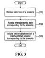
- FIG. 3is a flow chart for a method for enabling interoperable communications between at least two communication systems using at least two different communication protocols, according to the present invention.
- At least one of the communication systemsis a two-way radio system.
- the methodis implemented on an interoperability server, such as the one described with reference to FIG. 2 .
- step 202 of the methoda selection of a scenario is received.
- step 206interoperability data corresponding to the scenario is accessed.
- step 208the establishment of a communication session is initiated in accordance with the interoperability data corresponding to the scenario.
- the scenario identifieris the only information required to initiate the setting up of the communication session. Therefore, an end user at a user device can establish communication with a user device in another communication system having a different protocol simply by sending an identifier to the interoperability system.
- a user of a radio unit in a two-way radio systemcan enter a scenario identifier into his/her radio unit for a communication session with another radio system.
- the interoperability serverreceives the scenario identifier and initiates establishment of the communication session. Once the session is established user devices on both radio systems receive all signals broadcast in both systems on channels that they are monitoring.
- the gatewayshave the capability to select an individual channel.
- most radio control protocolsinclude the ability to select which frequency is used by the radio.
- the interoperability data accessed in Step 206includes channel information, which the interoperability server can use to instruct the gateway as to what channel to use for incoming and outgoing communications.
- the gateway/radio system combinationis limited to one session at a time, regardless of how many channels are available in the radio system. In some embodiments, this limitation is overcome by deploying more than one voice path for a gateway. The number of voice paths dictates the number of simultaneous sessions in which a radio system can be involved.
- a user of a radio unit in a radio systemcan enter a scenario identifier for an outside PSTN line.
- the interoperability serverinitiates establishment of a communication session between the radio system and the PSTN.
- the useris then prompted to enter a telephone number into the radio unit and a call to the respective telephone number is established. All radio units in the radio system are able to receive the call.
- the scenario identifieris sent using DTMF (Dual Tone Multi-Frequency) technology. In other embodiments, the scenario identifier is sent using IVR (Interactive Voice Response) technology. In still other embodiments, speech recognition technology is used.
- a userkeys in a code to access the IVR system or dials a number.
- the IVR systemthen prompts the user to provide a scenario identifier.
- the IVRwill provide the user with possible scenarios and corresponding scenario identifiers.
- the methodalso comprises receiving a request to perform any of the functions listed above with reference to FIG. 2 .
- the methodalso comprises receiving a PIN and verifying that the user device or user associated with the PIN has authorisation to initiate the requested communication session or to perform a requested function.
- FIG. 4is a block diagram of an interoperability data structure 300 .
- the interoperability data structure 300comprises scenario identifier data objects 302 , scenario information data objects 304 and connection data objects 306 .
- the scenario identifier data objects 302point to scenario information data objects 304 , which contain connections for each of a series of scenarios corresponding to the scenario identifier data objects.
- the scenario information data objects 304point to the connection data objects 306 which contain data for each connection listed in the series of scenarios. Examples of the data for the connections include connection device type, such as a radio or telephone, and signalling protocol, such as EIA tone or digital protocol.
- Table 2An example data structure according the embodiment of FIG. 4 is shown in Table 2:
- each scenariohas an associated scenario identifier that is three digits and associated connection information.
- a userneed only enter the three digits of the corresponding scenario identifier into the initiating user device and send it to the interoperability server.
- the interoperability systemis located on a distributed call management module (DCMM), such as that described in the Applicant's co-pending application Ser. No. 11/096,081.
- DCMMdistributed call management module
- FIG. 5depicts a communication network 400 in which an interoperability system 401 , in accordance with one embodiment of the present invention, is located on a DCMM 404 .
- the communication network 400comprises a packet network 402 in communication with various communication systems. Each communication system has user devices.
- the communication systemsare a PSTN 412 , a public IP network 416 , a radio system 424 , an IP radio system 426 , a packet based IP telephone network 430 and a radio system 438 .
- a dispatch centre 442having two operator workstations 444 and 446 .
- An example of a dispatch centre 442is a PSAP (Public Safety Answering Point).
- the user device in communication with the public IP network 416is a remote operator workstation 418 .
- the user device supported by the radio system 424is a radio unit 425 .
- Radio system 424is in communication with the packet network 402 through a radio gateway 422 , which is located on a DCMM 420 .
- the user device for the IP radio system 426is an IP radio unit 428 .
- the user device for the IP telephone network 430is an IP telephony unit 432 .
- the user device for radio system 438is a radio unit 440 .
- Radio system 438is in communication with the packet network 402 through radio gateway 436 , which is located on DCMM 434 .
- the user device for the PSTN 412is a telephony unit 414 .
- the PSTN 412is in communication with the packet network 402 through telephone gateway 410 , which is located on DCMM 404 along with the interoperability system 401 .
- interoperability system 401is located on DCMM 404 .
- interoperability system 401can be located on any DCMM such as DCMM 420 or 434 or on multiple DCMMs.
- the interoperability system 401can be located on a separate server in communication with the packet network 402 .
- the interoperability system 401comprises an interoperability server 406 and an interoperability database 408 , which perform functions similar to the interoperability server 120 and the interoperability database 130 described with reference to FIG. 2 .
- the interoperability systemcan be implemented into a complex communication network. It will be appreciated that embodiments of the present invention are not limited to the number and types of communication systems in the embodiment of FIG. 5 .
- the user of radio unit 425has access to a menu of scenarios and associated scenario identifications.
- the scenariomay be a communication session with any number of the other user devices or communication systems.
- radio unit 425sends a scenario identifier corresponding to the scenario to the interoperability system 401 using DTMF technology.
- the interoperability server 406receives the scenario identifier.
- the radio unit 425also sends a PIN at the same time as the scenario identifier.
- the interoperability server 406prompts the radio unit 425 for the PIN.
- the interoperability server 406verifies that the PIN is valid and then obtains the connection data from the interoperability database 408 to set up the communication session in accordance with the scenario.
- a radio unitcan connect to another radio channel in real-time, connect to a telephone line in real-time, activate a predefined radio connection or patch, and/or deactivate a predefined radio connection or patch.
- the user of telephone unit 414has access to a menu of scenarios and associated scenario identifiers.
- the scenariomay be a communication session with any number of the other user devices or communication systems.
- telephone unit 414sends a scenario identifier corresponding to the scenario to the interoperability system 401 using IVR technology.
- the interoperability server 406receives the scenario identifier.
- the telephone unit 414also sends a PIN at the same time as the scenario identifier.
- the interoperability server 406prompts the telephone unit 414 for the PIN.
- the interoperability server 406verifies the PIN and then obtains the connection data from the interoperability database 408 to set up the communication session in accordance with the scenario.
- a telephone unitcan connect to a radio channel in real-time, activate a predefined radio connection or patch, and/or deactivate a predefined radio connection or patch.
- a user at a workstation 418 , 444 , or 446can access the interoperability database after entering a password and perform any of the following functions: activate a predefined radio connection or patch; deactivate a predefined radio connection patch; define a radio connection or patch; define a gateway; manage users; define schedules for a one-time patch; and define schedules for recurring connections or patches.
- the useris presented with a user interface at the workstation which comprises a menu of the functions.
- the user interfacealso includes a menu of the scenarios available and the corresponding scenario identifiers.
Landscapes
- Engineering & Computer Science (AREA)
- Computer Networks & Wireless Communication (AREA)
- Signal Processing (AREA)
- Mobile Radio Communication Systems (AREA)
- Communication Control (AREA)
Abstract
Description
| TABLE 1 | |
| Scenario | |
| Identifier | Gateway IP Address |
| 150 | IP Address of |
| 151 | IP Address of |
| 152 | IP Address of |
| TABLE 2 | ||
| Scenario | ||
| Identifier | Scenario | Connection Data |
| 123 | Gateway A to Gateway B | IP address for Gateway A |
| IP address for Gateway B | ||
| 456 | Gateway B to Gateway C | IP address for Gateway B |
| and Gateway D | IP address for Gateway C | |
| IP address for Gateway D | ||
Claims (18)
Priority Applications (5)
| Application Number | Priority Date | Filing Date | Title |
|---|---|---|---|
| US11/369,869US7676228B2 (en) | 2005-09-19 | 2006-03-08 | Radio interoperability system and method |
| EP06814841AEP1927242B1 (en) | 2005-09-19 | 2006-09-18 | Radio interoperability system and method |
| AT06814841TATE509467T1 (en) | 2005-09-19 | 2006-09-18 | RADIO INTEROPERABILITY SYSTEM AND METHOD |
| PCT/US2006/036249WO2007035614A1 (en) | 2005-09-19 | 2006-09-18 | Radio interoperability system and method |
| US12/719,654US8346263B2 (en) | 2005-09-19 | 2010-03-08 | Radio interoperability system and method |
Applications Claiming Priority (2)
| Application Number | Priority Date | Filing Date | Title |
|---|---|---|---|
| US71774605P | 2005-09-19 | 2005-09-19 | |
| US11/369,869US7676228B2 (en) | 2005-09-19 | 2006-03-08 | Radio interoperability system and method |
Related Child Applications (1)
| Application Number | Title | Priority Date | Filing Date |
|---|---|---|---|
| US12/719,654ContinuationUS8346263B2 (en) | 2005-09-19 | 2010-03-08 | Radio interoperability system and method |
Publications (2)
| Publication Number | Publication Date |
|---|---|
| US20070064630A1 US20070064630A1 (en) | 2007-03-22 |
| US7676228B2true US7676228B2 (en) | 2010-03-09 |
Family
ID=37561200
Family Applications (2)
| Application Number | Title | Priority Date | Filing Date |
|---|---|---|---|
| US11/369,869Active2029-01-07US7676228B2 (en) | 2005-09-19 | 2006-03-08 | Radio interoperability system and method |
| US12/719,654ActiveUS8346263B2 (en) | 2005-09-19 | 2010-03-08 | Radio interoperability system and method |
Family Applications After (1)
| Application Number | Title | Priority Date | Filing Date |
|---|---|---|---|
| US12/719,654ActiveUS8346263B2 (en) | 2005-09-19 | 2010-03-08 | Radio interoperability system and method |
Country Status (4)
| Country | Link |
|---|---|
| US (2) | US7676228B2 (en) |
| EP (1) | EP1927242B1 (en) |
| AT (1) | ATE509467T1 (en) |
| WO (1) | WO2007035614A1 (en) |
Cited By (4)
| Publication number | Priority date | Publication date | Assignee | Title |
|---|---|---|---|---|
| US20090041206A1 (en)* | 2007-03-05 | 2009-02-12 | Hobby Patrick L | Emergency Communications System |
| US8934934B1 (en) | 2007-03-05 | 2015-01-13 | Safecom 911, Inc. | Emergency radio communications system incorporating integral public safety radio bridging capability |
| US9414214B2 (en) | 2007-03-05 | 2016-08-09 | Safecom 911, Inc. | Emergency radio communications system incorporating integral public safety radio bridging capability |
| US9848311B1 (en) | 2014-08-01 | 2017-12-19 | Catalyst Communications Technologies | System and method for managing communications |
Families Citing this family (6)
| Publication number | Priority date | Publication date | Assignee | Title |
|---|---|---|---|---|
| US8254876B1 (en)* | 2006-01-04 | 2012-08-28 | Nextel Communications, Inc. | Systems and methods for supporting dispatch communications |
| US8385228B2 (en)* | 2008-01-03 | 2013-02-26 | Cisco Technology, Inc. | Communication paradigm switching based on link quality information |
| PL2236000T3 (en)* | 2008-01-22 | 2016-03-31 | Savox Communications Oy Ab Ltd | An arrangement and method for connecting an ad-hoc communication network to a permanent communication network via a half-duplex communication link |
| US8897179B2 (en)* | 2010-08-30 | 2014-11-25 | Cisco Technology, Inc. | Method and apparatus for detecting an offline radio resource in an interoperability system |
| EP2668582A4 (en) | 2011-01-28 | 2016-06-01 | Dun & Bradstreet Corp | LAYER ACCESS TO INVENTORY DATA |
| US20180242397A1 (en)* | 2015-08-31 | 2018-08-23 | Woei-jia Hwang | Radio Communication Method and System |
Citations (84)
| Publication number | Priority date | Publication date | Assignee | Title |
|---|---|---|---|---|
| US3881060A (en) | 1973-06-04 | 1975-04-29 | Bell Telephone Labor Inc | Emergency reporting system |
| US4029901A (en) | 1975-11-13 | 1977-06-14 | Motorola, Inc. | Control center for a communications system with interchannel patching capabilities |
| US4677656A (en) | 1984-06-19 | 1987-06-30 | Motorola, Inc. | Telephone-radio interconnect system |
| US4893325A (en) | 1988-09-23 | 1990-01-09 | Rockwell International Corporation | Integrated public safety answering point system |
| US5206903A (en) | 1990-12-26 | 1993-04-27 | At&T Bell Laboratories | Automatic call distribution based on matching required skills with agents skills |
| US5239570A (en) | 1990-07-25 | 1993-08-24 | Teltone Corporation | 9-1-1 Switched access system |
| US5311569A (en) | 1992-06-05 | 1994-05-10 | At&T Bell Laboratories | Line-based public safety answering point |
| US5392277A (en) | 1993-06-11 | 1995-02-21 | At&T Corp. | Routing to intelligence |
| US5428819A (en)* | 1993-04-27 | 1995-06-27 | Motorola, Inc. | Method and apparatus for radio frequency bandwidth sharing among heterogeneous radio communication system |
| US5479482A (en) | 1993-08-30 | 1995-12-26 | At&T Corp. | Cellular terminal for providing public emergency call location information |
| US5481545A (en) | 1991-08-26 | 1996-01-02 | Ericsson Inc. | Conventional network interface for multisite RF trunking system |
| US5696809A (en) | 1995-06-22 | 1997-12-09 | Bell Atlantic Network Services, Inc. | Advanced intelligent network based computer architecture for concurrent delivery of voice and text data using failure management system |
| US5841848A (en) | 1996-05-07 | 1998-11-24 | Lucent Technologies Inc. | System and method for completing telephone calls to emergency telephone numbers in highly concentrated access systems |
| US5844974A (en) | 1995-05-22 | 1998-12-01 | Nec Corporation | Emergency telephone communications system |
| US5862485A (en) | 1995-03-31 | 1999-01-19 | Motorola, Inc. | Method and apparatus for allocating communication resources to support priority communications in a communication system |
| US5867562A (en) | 1996-04-17 | 1999-02-02 | Scherer; Gordon F. | Call processing system with call screening |
| US5898757A (en) | 1996-07-12 | 1999-04-27 | At&T Corp | Method and system for processing emergency service calls |
| US5905792A (en) | 1997-02-10 | 1999-05-18 | Genesys Telecommunications Laboratories, Inc. | External positivistic forward transfer in call routing systems |
| US5915010A (en) | 1996-06-10 | 1999-06-22 | Teknekron Infoswitch | System, method and user interface for data announced call transfer |
| US5937355A (en) | 1995-12-07 | 1999-08-10 | Telefonaktiebolaget Lm Ericsson (Publ) | Emergency call handling in a cellular telecommunication system |
| US5937051A (en) | 1993-07-08 | 1999-08-10 | Teknekron Infoswitch Corporation | Method and system for transferring calls and call-related data between a plurality of call centers |
| US5937334A (en) | 1996-09-30 | 1999-08-10 | Fred Peterson | Radio communications and telephone network interface system |
| US5940497A (en) | 1997-02-10 | 1999-08-17 | Genesys Telecommunications Laboratories, Inc. | Statistically-predictive and agent-predictive call routing |
| US5999965A (en) | 1996-08-20 | 1999-12-07 | Netspeak Corporation | Automatic call distribution server for computer telephony communications |
| US6009163A (en) | 1997-07-03 | 1999-12-28 | U S West, Inc. | Method and system for regulating incoming calls from multiple points of origination |
| US6067356A (en) | 1997-09-20 | 2000-05-23 | Alcatel | Method of routing emergency calls |
| US6075853A (en) | 1997-03-31 | 2000-06-13 | Sbc Technology Resources, Inc. | Apparatus and method for intelligent call routing and call return |
| US6128481A (en) | 1997-10-22 | 2000-10-03 | Telefonaktiebolaget L M Ericsson (Publ) | System and method of routing emergency services calls in a radio telecommunications network |
| CA2306638A1 (en) | 1999-04-04 | 2000-11-04 | Mitel Corporation | Multi-line telephone system emergency call processing |
| US6175562B1 (en) | 1997-04-29 | 2001-01-16 | Intervoice Limited Partnership | Switchless call processing |
| US6175564B1 (en) | 1995-10-25 | 2001-01-16 | Genesys Telecommunications Laboratories, Inc | Apparatus and methods for managing multiple internet protocol capable call centers |
| US6185205B1 (en) | 1998-06-01 | 2001-02-06 | Motorola, Inc. | Method and apparatus for providing global communications interoperability |
| US6198920B1 (en) | 1995-06-01 | 2001-03-06 | Padcom, Inc. | Apparatus and method for intelligent routing of data between a remote device and a host system |
| US6233445B1 (en) | 1997-01-14 | 2001-05-15 | Ericsson, Inc. | Establishing emergency calls within a mobile telecommunications network |
| EP1109417A1 (en) | 1999-12-17 | 2001-06-20 | Nortel Networks Limited | System and method for unifying the implementation and processing mobile communications and a unified mobility manager for providing such communications |
| US6252943B1 (en) | 1999-11-03 | 2001-06-26 | At&T Corp | Telephone network having dual gateway interconnection architecture for handling emergency services |
| US6256489B1 (en) | 1997-04-24 | 2001-07-03 | Lucent Technologies Inc. | Enhanced emergency service for ISDN based emergency services in a wireless telecommunications system |
| WO2001065868A1 (en) | 2000-03-01 | 2001-09-07 | Motorola Inc. | Transmission within a wireless communication system |
| WO2001065763A2 (en) | 2000-02-29 | 2001-09-07 | 3Com Corporation | Providing location information for telephony over data communication networks |
| US6289083B1 (en) | 2000-02-16 | 2001-09-11 | Rockwell Electronic Commerce Corp. | Method of identifying a location of a source of an emergency call in a call center environment |
| WO2001067733A1 (en) | 2000-03-04 | 2001-09-13 | Lucent Technologies Inc. | System for providing expanded emergency service communication in a telecommunication network |
| US6292542B1 (en) | 1999-08-11 | 2001-09-18 | At&T Corp. | Method and apparatus for handling an in-call request for emergency services |
| US20010036176A1 (en)* | 2000-02-28 | 2001-11-01 | Girard Gregory D. | Apparatus and method for telephony service interface to software switch controller |
| US20010040887A1 (en) | 1997-10-09 | 2001-11-15 | Yuri Shtivelman | Apparatus and methods enhancing call routing to and within call-centers |
| US6324279B1 (en) | 1998-08-04 | 2001-11-27 | At&T Corp. | Method for exchanging signaling messages in two phases |
| US6327342B1 (en) | 1999-05-28 | 2001-12-04 | Matthew Stephen Mobley | E911 backup system for emergency 911 call answering systems |
| US6330324B1 (en) | 1997-12-09 | 2001-12-11 | Sbc Technology Resources, Inc. | Geographical call routing for a non-emergency calling service |
| US6332022B1 (en) | 1997-12-22 | 2001-12-18 | Nortel Networks Limited | Method and apparatus for routing emergency services calls in an intelligent network |
| US20020001300A1 (en) | 1996-07-09 | 2002-01-03 | Alec Miloslavsky | Internet protocol call-in centers and establishing remote agents |
| US6392999B1 (en) | 1999-08-10 | 2002-05-21 | Lucent Technologies Inc. | Conferencing and announcement generation for wireless VoIP and VoATM calls |
| US20020068584A1 (en) | 2000-12-05 | 2002-06-06 | Nortel Networks Limited | Method and system for transmitting data to a mobile device |
| US20020110104A1 (en) | 2001-02-13 | 2002-08-15 | Telefonaktiebolaget Lm Ericsson (Publ). | Hybrid media gateway control function providing circuit-switched access to a packet-switched radio telecommunications network |
| US6453038B1 (en) | 1998-06-03 | 2002-09-17 | Avaya Technology Corp. | System for integrating agent database access skills in call center agent assignment applications |
| US20020138446A1 (en)* | 2000-09-14 | 2002-09-26 | Thierry Antonin | System and method for providing security for financial services terminals with a document driven interface |
| US20020197977A1 (en) | 2001-06-25 | 2002-12-26 | Frank Brooks | Control and messaging during emergency calls |
| US20030007469A1 (en) | 2001-07-05 | 2003-01-09 | Daley Robert S. | System and method for voice over IP |
| US20030053434A1 (en) | 2001-08-03 | 2003-03-20 | At&T Corp. | Method and apparatus for delivering IPP2T (IP-push-to-talk) wireless LAN mobile radio service |
| US20030058827A1 (en) | 2001-08-03 | 2003-03-27 | At&T Corp. | Architecture and method for using IEEE 802.11-like wireless LAN system to emulate private land mobile radio system (PLMRS) radio service |
| US20030139174A1 (en) | 2001-12-13 | 2003-07-24 | Far Eastone Telecommunications Co., Ltd. | Common service platform and software |
| US20030158954A1 (en)* | 2002-02-19 | 2003-08-21 | Williams Terry L. | Software-defined radio communication protocol translator |
| US20030179772A1 (en) | 2000-09-25 | 2003-09-25 | Sven Niklasson | Method and system for exchanging information between communication networks |
| US6654455B1 (en) | 1999-06-09 | 2003-11-25 | Oki Electric Industry Co., Ltd. | IP conference telephone system compatible with IP-PBX systems |
| US20040053607A1 (en) | 2000-10-13 | 2004-03-18 | Hans Ronneke | Communication system supporting wireless communication of packet data and method and arrangement relating thereto |
| US6744859B1 (en) | 2002-05-21 | 2004-06-01 | Intrado Inc. | System and apparatus for providing telephone communication between a caller and a special number call answering facility |
| US6744858B1 (en) | 2001-01-26 | 2004-06-01 | Telcontrol, Inc. | System and method for supporting multiple call centers |
| US20040105529A1 (en) | 2000-11-13 | 2004-06-03 | Angelo Salvucci | Real-time incident and response information messaging in a system for the automatic notification that an emergency call has occurred from a wireless telecommunication device |
| US6771742B2 (en) | 2001-11-05 | 2004-08-03 | Intrado Inc. | Geographic routing of emergency service call center emergency calls |
| EP1453248A2 (en) | 2003-02-25 | 2004-09-01 | NTT DoCoMo, Inc. | System and method for controlling network, network controlling apparatus, and mobile terminal |
| US20040190468A1 (en) | 2003-03-24 | 2004-09-30 | Jaakko Saijonmaa | Group communication in a communication network |
| US20050030966A1 (en) | 2003-08-06 | 2005-02-10 | Zhijun Cai | Method and apparatus for providing session data to a subscriber to a multimedia broadcast multicast service |
| WO2005015804A2 (en) | 2003-08-06 | 2005-02-17 | Motorola, Inc. , A Corporation Of The State Of Delaware | Method and apparatus for providing session data to a subscriber to a multimedia broadcast multicast service |
| US20050090225A1 (en) | 2004-11-16 | 2005-04-28 | Om2 Technology Inc. | A Simplified Second Generation Enhanced Emergency Communications System SSGE-911 |
| US6888803B1 (en) | 1998-12-22 | 2005-05-03 | Nortel Networks Limited | System, method, and computer program product for connectivity of wireless base station to PSTN via an IP data network |
| US20050141689A1 (en)* | 2003-12-31 | 2005-06-30 | Wengrovitz Michael S. | Personal call routing between PBX and SIP networks |
| US20050201358A1 (en) | 2004-03-13 | 2005-09-15 | Intrado Inc. | Rotating media channels between resources of an emergency services network and conforming emergency systems |
| US20050201528A1 (en) | 2004-03-13 | 2005-09-15 | Intrado Inc. | Bi-directional messaging for an emergency services network |
| US20050201527A1 (en) | 2004-03-13 | 2005-09-15 | Intrado Inc. | Communication network for providing emergency services |
| US20050201529A1 (en) | 2004-03-13 | 2005-09-15 | Intrado Inc. | Method and apparatus for increasing the reliability of an emergency call communication network |
| US20050201359A1 (en) | 2004-03-13 | 2005-09-15 | Intrado Inc. | Dynamically establishing media channels between resources of an emergency services network and conforming emergency systems |
| US6963557B2 (en) | 2003-03-29 | 2005-11-08 | Intrado Inc. | System and method for routing telephone calls involving internet protocol network |
| US6993118B2 (en) | 2000-03-04 | 2006-01-31 | Intrado Inc. | System and method for accessing personal information relating to a caller in a remote telecommunication network |
| US20060083220A1 (en)* | 2004-10-14 | 2006-04-20 | Cisco Technology, Inc. | Transport of DTMF tones over VOATM/VOIP networks |
| US20060120347A1 (en)* | 2004-12-03 | 2006-06-08 | Cisco Technology, Inc. | Voice over internet protocol (VOIP) subcell multiplexing |
| US7080157B2 (en) | 1999-01-11 | 2006-07-18 | Fastforward Networks, Inc. | Performing multicast communication in computer networks by using overlay routing |
Family Cites Families (11)
| Publication number | Priority date | Publication date | Assignee | Title |
|---|---|---|---|---|
| US5311589A (en)* | 1992-03-31 | 1994-05-10 | At&T Bell Laboratories | Apparatus and method for audible signaling tone recognition |
| CN1090886C (en)* | 1994-02-22 | 2002-09-11 | 松下电器产业株式会社 | Earphone |
| CA2217275C (en)* | 1997-10-03 | 2005-08-16 | Newbridge Networks Corporation | Multiple internetworking realms within an internetworking device |
| DE19834634C2 (en) | 1998-07-31 | 2002-06-20 | Siemens Ag | Communication arrangement with at least one central communication device to which wireless network termination devices can be connected for the connection of communication terminals |
| US6661882B1 (en) | 1999-04-27 | 2003-12-09 | Citibank, N.A. | System and method for automated telephone message routing using an altered ANI |
| JP2002221676A (en)* | 2001-01-25 | 2002-08-09 | Furukawa Electric Co Ltd:The | Variable optical attenuator |
| US8108520B2 (en)* | 2003-06-19 | 2012-01-31 | Nokia Corporation | Apparatus and method for providing quality of service for a network data connection |
| US7903638B2 (en)* | 2005-02-09 | 2011-03-08 | Alcatel Lucent | Communication link bonding apparatus and methods |
| GB2424146A (en)* | 2005-03-09 | 2006-09-13 | Agilent Technologies Inc | Stand-alone car receiver |
| US8881557B2 (en) | 2012-01-14 | 2014-11-11 | Marc Franklin McEachern | Adjustable position blocking device for sliding closures |
| US9076863B2 (en) | 2013-07-17 | 2015-07-07 | Texas Instruments Incorporated | Semiconductor structure with a doped region between two deep trench isolation structures |
- 2006
- 2006-03-08USUS11/369,869patent/US7676228B2/enactiveActive
- 2006-09-18WOPCT/US2006/036249patent/WO2007035614A1/enactiveApplication Filing
- 2006-09-18ATAT06814841Tpatent/ATE509467T1/ennot_activeIP Right Cessation
- 2006-09-18EPEP06814841Apatent/EP1927242B1/enactiveActive
- 2010
- 2010-03-08USUS12/719,654patent/US8346263B2/enactiveActive
Patent Citations (91)
| Publication number | Priority date | Publication date | Assignee | Title |
|---|---|---|---|---|
| US3881060A (en) | 1973-06-04 | 1975-04-29 | Bell Telephone Labor Inc | Emergency reporting system |
| US4029901A (en) | 1975-11-13 | 1977-06-14 | Motorola, Inc. | Control center for a communications system with interchannel patching capabilities |
| US4677656A (en) | 1984-06-19 | 1987-06-30 | Motorola, Inc. | Telephone-radio interconnect system |
| US4893325A (en) | 1988-09-23 | 1990-01-09 | Rockwell International Corporation | Integrated public safety answering point system |
| US5239570A (en) | 1990-07-25 | 1993-08-24 | Teltone Corporation | 9-1-1 Switched access system |
| US5206903A (en) | 1990-12-26 | 1993-04-27 | At&T Bell Laboratories | Automatic call distribution based on matching required skills with agents skills |
| US5481545A (en) | 1991-08-26 | 1996-01-02 | Ericsson Inc. | Conventional network interface for multisite RF trunking system |
| US5311569A (en) | 1992-06-05 | 1994-05-10 | At&T Bell Laboratories | Line-based public safety answering point |
| US5428819A (en)* | 1993-04-27 | 1995-06-27 | Motorola, Inc. | Method and apparatus for radio frequency bandwidth sharing among heterogeneous radio communication system |
| US5392277A (en) | 1993-06-11 | 1995-02-21 | At&T Corp. | Routing to intelligence |
| US5937051A (en) | 1993-07-08 | 1999-08-10 | Teknekron Infoswitch Corporation | Method and system for transferring calls and call-related data between a plurality of call centers |
| US5479482A (en) | 1993-08-30 | 1995-12-26 | At&T Corp. | Cellular terminal for providing public emergency call location information |
| US5862485A (en) | 1995-03-31 | 1999-01-19 | Motorola, Inc. | Method and apparatus for allocating communication resources to support priority communications in a communication system |
| US5844974A (en) | 1995-05-22 | 1998-12-01 | Nec Corporation | Emergency telephone communications system |
| US6198920B1 (en) | 1995-06-01 | 2001-03-06 | Padcom, Inc. | Apparatus and method for intelligent routing of data between a remote device and a host system |
| US5696809A (en) | 1995-06-22 | 1997-12-09 | Bell Atlantic Network Services, Inc. | Advanced intelligent network based computer architecture for concurrent delivery of voice and text data using failure management system |
| US6175564B1 (en) | 1995-10-25 | 2001-01-16 | Genesys Telecommunications Laboratories, Inc | Apparatus and methods for managing multiple internet protocol capable call centers |
| US5937355A (en) | 1995-12-07 | 1999-08-10 | Telefonaktiebolaget Lm Ericsson (Publ) | Emergency call handling in a cellular telecommunication system |
| US5867562A (en) | 1996-04-17 | 1999-02-02 | Scherer; Gordon F. | Call processing system with call screening |
| US5841848A (en) | 1996-05-07 | 1998-11-24 | Lucent Technologies Inc. | System and method for completing telephone calls to emergency telephone numbers in highly concentrated access systems |
| US5915010A (en) | 1996-06-10 | 1999-06-22 | Teknekron Infoswitch | System, method and user interface for data announced call transfer |
| US20020001300A1 (en) | 1996-07-09 | 2002-01-03 | Alec Miloslavsky | Internet protocol call-in centers and establishing remote agents |
| US5898757A (en) | 1996-07-12 | 1999-04-27 | At&T Corp | Method and system for processing emergency service calls |
| US5999965A (en) | 1996-08-20 | 1999-12-07 | Netspeak Corporation | Automatic call distribution server for computer telephony communications |
| US5937334A (en) | 1996-09-30 | 1999-08-10 | Fred Peterson | Radio communications and telephone network interface system |
| US6233445B1 (en) | 1997-01-14 | 2001-05-15 | Ericsson, Inc. | Establishing emergency calls within a mobile telecommunications network |
| US5970065A (en) | 1997-02-10 | 1999-10-19 | Genesys Telecommunications Laboratories, Inc. | Uniform control of mixed platforms in telephony |
| US5940497A (en) | 1997-02-10 | 1999-08-17 | Genesys Telecommunications Laboratories, Inc. | Statistically-predictive and agent-predictive call routing |
| US20010043586A1 (en) | 1997-02-10 | 2001-11-22 | Alec Miloslavsky | Apparatus and methods enhancing call routing to and within call-centers |
| US5905792A (en) | 1997-02-10 | 1999-05-18 | Genesys Telecommunications Laboratories, Inc. | External positivistic forward transfer in call routing systems |
| US6175563B1 (en) | 1997-02-10 | 2001-01-16 | Genesys Telecommunications Laboratories, Inc. | Parallel data transfer and synchronization in computer-simulated telephony |
| US6185287B1 (en) | 1997-02-10 | 2001-02-06 | Genesys Telecommunications Laboratories, Inc. | Parallel data transfer and synchronization |
| US6075853A (en) | 1997-03-31 | 2000-06-13 | Sbc Technology Resources, Inc. | Apparatus and method for intelligent call routing and call return |
| US6256489B1 (en) | 1997-04-24 | 2001-07-03 | Lucent Technologies Inc. | Enhanced emergency service for ISDN based emergency services in a wireless telecommunications system |
| US6175562B1 (en) | 1997-04-29 | 2001-01-16 | Intervoice Limited Partnership | Switchless call processing |
| US6009163A (en) | 1997-07-03 | 1999-12-28 | U S West, Inc. | Method and system for regulating incoming calls from multiple points of origination |
| US6067356A (en) | 1997-09-20 | 2000-05-23 | Alcatel | Method of routing emergency calls |
| US20010040887A1 (en) | 1997-10-09 | 2001-11-15 | Yuri Shtivelman | Apparatus and methods enhancing call routing to and within call-centers |
| US6128481A (en) | 1997-10-22 | 2000-10-03 | Telefonaktiebolaget L M Ericsson (Publ) | System and method of routing emergency services calls in a radio telecommunications network |
| US6330324B1 (en) | 1997-12-09 | 2001-12-11 | Sbc Technology Resources, Inc. | Geographical call routing for a non-emergency calling service |
| US6332022B1 (en) | 1997-12-22 | 2001-12-18 | Nortel Networks Limited | Method and apparatus for routing emergency services calls in an intelligent network |
| US6185205B1 (en) | 1998-06-01 | 2001-02-06 | Motorola, Inc. | Method and apparatus for providing global communications interoperability |
| US6453038B1 (en) | 1998-06-03 | 2002-09-17 | Avaya Technology Corp. | System for integrating agent database access skills in call center agent assignment applications |
| US6324279B1 (en) | 1998-08-04 | 2001-11-27 | At&T Corp. | Method for exchanging signaling messages in two phases |
| US6888803B1 (en) | 1998-12-22 | 2005-05-03 | Nortel Networks Limited | System, method, and computer program product for connectivity of wireless base station to PSTN via an IP data network |
| US7080157B2 (en) | 1999-01-11 | 2006-07-18 | Fastforward Networks, Inc. | Performing multicast communication in computer networks by using overlay routing |
| CA2306638A1 (en) | 1999-04-04 | 2000-11-04 | Mitel Corporation | Multi-line telephone system emergency call processing |
| US6327342B1 (en) | 1999-05-28 | 2001-12-04 | Matthew Stephen Mobley | E911 backup system for emergency 911 call answering systems |
| US6654455B1 (en) | 1999-06-09 | 2003-11-25 | Oki Electric Industry Co., Ltd. | IP conference telephone system compatible with IP-PBX systems |
| US6392999B1 (en) | 1999-08-10 | 2002-05-21 | Lucent Technologies Inc. | Conferencing and announcement generation for wireless VoIP and VoATM calls |
| US6292542B1 (en) | 1999-08-11 | 2001-09-18 | At&T Corp. | Method and apparatus for handling an in-call request for emergency services |
| US6252943B1 (en) | 1999-11-03 | 2001-06-26 | At&T Corp | Telephone network having dual gateway interconnection architecture for handling emergency services |
| EP1109417A1 (en) | 1999-12-17 | 2001-06-20 | Nortel Networks Limited | System and method for unifying the implementation and processing mobile communications and a unified mobility manager for providing such communications |
| US6563919B1 (en) | 1999-12-17 | 2003-05-13 | Nortel Networks Limited | System and method for unifying the implementation and processing of mobile communications and a unified mobility manager for providing such communications |
| US6289083B1 (en) | 2000-02-16 | 2001-09-11 | Rockwell Electronic Commerce Corp. | Method of identifying a location of a source of an emergency call in a call center environment |
| US20010036176A1 (en)* | 2000-02-28 | 2001-11-01 | Girard Gregory D. | Apparatus and method for telephony service interface to software switch controller |
| WO2001065763A2 (en) | 2000-02-29 | 2001-09-07 | 3Com Corporation | Providing location information for telephony over data communication networks |
| WO2001065868A1 (en) | 2000-03-01 | 2001-09-07 | Motorola Inc. | Transmission within a wireless communication system |
| WO2001067733A1 (en) | 2000-03-04 | 2001-09-13 | Lucent Technologies Inc. | System for providing expanded emergency service communication in a telecommunication network |
| US6993118B2 (en) | 2000-03-04 | 2006-01-31 | Intrado Inc. | System and method for accessing personal information relating to a caller in a remote telecommunication network |
| US6587545B1 (en) | 2000-03-04 | 2003-07-01 | Lucent Technologies Inc. | System for providing expanded emergency service communication in a telecommunication network |
| US20020138446A1 (en)* | 2000-09-14 | 2002-09-26 | Thierry Antonin | System and method for providing security for financial services terminals with a document driven interface |
| US20030179772A1 (en) | 2000-09-25 | 2003-09-25 | Sven Niklasson | Method and system for exchanging information between communication networks |
| US20040053607A1 (en) | 2000-10-13 | 2004-03-18 | Hans Ronneke | Communication system supporting wireless communication of packet data and method and arrangement relating thereto |
| US20040105529A1 (en) | 2000-11-13 | 2004-06-03 | Angelo Salvucci | Real-time incident and response information messaging in a system for the automatic notification that an emergency call has occurred from a wireless telecommunication device |
| US20020068584A1 (en) | 2000-12-05 | 2002-06-06 | Nortel Networks Limited | Method and system for transmitting data to a mobile device |
| US6744858B1 (en) | 2001-01-26 | 2004-06-01 | Telcontrol, Inc. | System and method for supporting multiple call centers |
| US20020110104A1 (en) | 2001-02-13 | 2002-08-15 | Telefonaktiebolaget Lm Ericsson (Publ). | Hybrid media gateway control function providing circuit-switched access to a packet-switched radio telecommunications network |
| US20020197977A1 (en) | 2001-06-25 | 2002-12-26 | Frank Brooks | Control and messaging during emergency calls |
| US20030007469A1 (en) | 2001-07-05 | 2003-01-09 | Daley Robert S. | System and method for voice over IP |
| US20030058827A1 (en) | 2001-08-03 | 2003-03-27 | At&T Corp. | Architecture and method for using IEEE 802.11-like wireless LAN system to emulate private land mobile radio system (PLMRS) radio service |
| US20030053434A1 (en) | 2001-08-03 | 2003-03-20 | At&T Corp. | Method and apparatus for delivering IPP2T (IP-push-to-talk) wireless LAN mobile radio service |
| US20040184584A1 (en) | 2001-11-05 | 2004-09-23 | Intrado Inc. | Geographic routing of emergency service call center emergency calls |
| US6771742B2 (en) | 2001-11-05 | 2004-08-03 | Intrado Inc. | Geographic routing of emergency service call center emergency calls |
| US20030139174A1 (en) | 2001-12-13 | 2003-07-24 | Far Eastone Telecommunications Co., Ltd. | Common service platform and software |
| US20030158954A1 (en)* | 2002-02-19 | 2003-08-21 | Williams Terry L. | Software-defined radio communication protocol translator |
| US6744859B1 (en) | 2002-05-21 | 2004-06-01 | Intrado Inc. | System and apparatus for providing telephone communication between a caller and a special number call answering facility |
| EP1453248A2 (en) | 2003-02-25 | 2004-09-01 | NTT DoCoMo, Inc. | System and method for controlling network, network controlling apparatus, and mobile terminal |
| US20040190468A1 (en) | 2003-03-24 | 2004-09-30 | Jaakko Saijonmaa | Group communication in a communication network |
| US6963557B2 (en) | 2003-03-29 | 2005-11-08 | Intrado Inc. | System and method for routing telephone calls involving internet protocol network |
| US20050030966A1 (en) | 2003-08-06 | 2005-02-10 | Zhijun Cai | Method and apparatus for providing session data to a subscriber to a multimedia broadcast multicast service |
| WO2005015804A2 (en) | 2003-08-06 | 2005-02-17 | Motorola, Inc. , A Corporation Of The State Of Delaware | Method and apparatus for providing session data to a subscriber to a multimedia broadcast multicast service |
| US20050141689A1 (en)* | 2003-12-31 | 2005-06-30 | Wengrovitz Michael S. | Personal call routing between PBX and SIP networks |
| US20050201358A1 (en) | 2004-03-13 | 2005-09-15 | Intrado Inc. | Rotating media channels between resources of an emergency services network and conforming emergency systems |
| US20050201529A1 (en) | 2004-03-13 | 2005-09-15 | Intrado Inc. | Method and apparatus for increasing the reliability of an emergency call communication network |
| US20050201359A1 (en) | 2004-03-13 | 2005-09-15 | Intrado Inc. | Dynamically establishing media channels between resources of an emergency services network and conforming emergency systems |
| US20050201527A1 (en) | 2004-03-13 | 2005-09-15 | Intrado Inc. | Communication network for providing emergency services |
| US20050201528A1 (en) | 2004-03-13 | 2005-09-15 | Intrado Inc. | Bi-directional messaging for an emergency services network |
| US20060083220A1 (en)* | 2004-10-14 | 2006-04-20 | Cisco Technology, Inc. | Transport of DTMF tones over VOATM/VOIP networks |
| US20050090225A1 (en) | 2004-11-16 | 2005-04-28 | Om2 Technology Inc. | A Simplified Second Generation Enhanced Emergency Communications System SSGE-911 |
| US20060120347A1 (en)* | 2004-12-03 | 2006-06-08 | Cisco Technology, Inc. | Voice over internet protocol (VOIP) subcell multiplexing |
Non-Patent Citations (24)
| Title |
|---|
| Cisco IP Telephony Network Design Guide, Cisco CallManager Release 3.0. Corporate Headquarters, Cisco Systems, Inc. San Jose, CA. Customer Order No. DOC-7811103; Text Part No. 7811103-01. |
| Deering, S.; Host Extensions for IP Multicasting; Aug. 1998, pp. 1-15. http://www.ietf.org/rfc/rfc1112.txt. |
| E9-1-1 Systems-Product Guide, Software Release B:2.1, CML Public Safety Systems, Jul. 1999. |
| Fenner, W.; Internet Group Management Protocol, Version 2; Nov. 1997; pp. 1-15. |
| Final Rejection by Examiner dated Aug. 17, 2007 issued in U.S. Appl. No. 11/095,465, filed Apr. 1, 2005. |
| http://www.vega-signaling.com/RadioDispatch/products.nsf/pages/Product-Type=Portable%20Interoperability. |
| http://www.zetron.com/pages/english/products/landmob2/html. |
| IP Products White Paper; Vega Telex Signalling Product Company; Aug. 9, 2002. |
| NENA Generic Standards for E9-1-1 PSAP Equipment, NENA PSAP Standards Sub-Committee, NENA-04-001, Issue 1, Jun. 20, 1996. |
| NENA Generic Standards for E9-1-1 PSAP Equipment. NENA Technical Reference. NENA-04-001 Issue 1, Jun. 20, 1996. Prepared by: National Emergency Number Association (NENA) PSAB Standards Sub-Committee. Published by NENA. Printed in U.S.A. |
| NENA Recommended Generic Standards Dealing with Network Interface for E9-1-1 and Emerging Technologies, NENA PSAP Standards Committee, NENA-03-XXX, Draft Issue 1.06, Sep. 17, 2000. |
| NENA Recommended Generic Standards Dealing with Network Interface for E9-1-1 and Emerging Technologies. NENA Technical Reference. NENA-03-XXXX Draft Issue 1.01, Jul. 13, 2000. Generic Standards for E9-1-1 and Emerging Technologies. Prepared by: National Emergency Number Association (NENA) PSAP Standards Sub-Committee. Published by NENA. Printed in U.S.A. |
| NENA Recommended Generic Standards for E9-1-1 PSAP Equipment, NENA CPE/PSAP Standards Technical Committee, NENA-04-001, Issue 2, Mar. 2001. |
| NENA Standard, Generic Requirements for an Enhanced 9-1-1 Selective Routing Switch, NENA Network Technical Committee, NENA-03-005, Jan. 2004. |
| Network Access Radio; Catalyst Communications Technologies, Inc.:: Network Access Radio; pp. 1-3. http://www.catcomtec.com/index2.php?option=com-content&task-view&id=47&Itemid= . . . . |
| Non-Final Rejection by Examiner dated Feb. 9, 2007 issued in U.S. Appl. No. 11/095,465, filed Apr. 1, 2005. |
| Non-Final Rejection by Examiner dated Nov. 30, 2007 issued in U.S. Appl. No. 11/095,465, filed Apr. 1, 2005. |
| P25IP Technical Overview; P25IP. Secure and Reliable Digital Voice and Data Communications; Tyco/Electronics. |
| Panossian et al.: Towards Providing Enhanced 911 Emergency Service In IP Telephony. Department of Computer Networking, University of Missouri-Kansas City. Nov. 1998. Revised: Aug. 1999. |
| Panossian, Serge G., "A Conceptual Architecture for Enhanced 911 Emergency Service for IP Telephony", Masters Thesis presented to the Faculty of the University of Missouri-Kansas City, Dec. 18, 1997. |
| Reed, et al.: An Overview of the Challenges and Progress in Meeting the E-911 Requirement for Location Service. IEEE Communications Magazine, Apr. 1998. pp. 30-37. |
| Schulzrinne: Providing Emergency Call Services for SIP-based Internet Telephony. Internet Engineering Task Force. Columbia U., Internet Draft. Jul. 13, 2000. Expires: Dec. 2000. |
| U.S. Appl. No. 60/264,242, filed Jun. 1, 2004, Ryan, et al. |
| Wave (Wide Area Voice Environment); Twisted Pair Solutions. |
Cited By (11)
| Publication number | Priority date | Publication date | Assignee | Title |
|---|---|---|---|---|
| US20090041206A1 (en)* | 2007-03-05 | 2009-02-12 | Hobby Patrick L | Emergency Communications System |
| US7813750B2 (en)* | 2007-03-05 | 2010-10-12 | Hobby Patrick L | Emergency radio communications system incorporating integral public safety radio bridging capability |
| US8934934B1 (en) | 2007-03-05 | 2015-01-13 | Safecom 911, Inc. | Emergency radio communications system incorporating integral public safety radio bridging capability |
| US9414214B2 (en) | 2007-03-05 | 2016-08-09 | Safecom 911, Inc. | Emergency radio communications system incorporating integral public safety radio bridging capability |
| US9736867B2 (en) | 2007-03-05 | 2017-08-15 | Safecom 911, Inc. | Emergency radio communications system incorporating integral public safety radio bridging capability |
| US9860923B2 (en) | 2007-03-05 | 2018-01-02 | Safecom 911, Inc. | Emergency radio communications system incorporating integral public safety radio bridging capability |
| US9949299B2 (en) | 2007-03-05 | 2018-04-17 | Safecom 911, Inc. | Emergency radio communications system incorporating integral public safety radio bridging capability |
| US10225883B2 (en) | 2007-03-05 | 2019-03-05 | Safecom 911, Inc. | Emergency radio communications system incorporating integral public safety radio bridging capability |
| US10448451B2 (en) | 2007-03-05 | 2019-10-15 | Safecom 911, Inc. | Emergency radio communications system incorporating integral public safety radio bridging capability |
| US10716166B2 (en) | 2007-03-05 | 2020-07-14 | Safecom 911, Inc. | Emergency radio communications system incorporating integral public safety radio bridging capability |
| US9848311B1 (en) | 2014-08-01 | 2017-12-19 | Catalyst Communications Technologies | System and method for managing communications |
Also Published As
| Publication number | Publication date |
|---|---|
| US8346263B2 (en) | 2013-01-01 |
| EP1927242B1 (en) | 2011-05-11 |
| WO2007035614A1 (en) | 2007-03-29 |
| US20100165924A1 (en) | 2010-07-01 |
| US20070064630A1 (en) | 2007-03-22 |
| EP1927242A1 (en) | 2008-06-04 |
| ATE509467T1 (en) | 2011-05-15 |
Similar Documents
| Publication | Publication Date | Title |
|---|---|---|
| US8346263B2 (en) | Radio interoperability system and method | |
| US7580706B2 (en) | Methods for enhanced communication between a plurality of communication systems | |
| US8194647B2 (en) | Internet protocol radio dispatch system and method | |
| US7907551B2 (en) | Voice over internet protocol (VoIP) location based 911 conferencing | |
| US7369530B2 (en) | Apparatus and method for interfacing packet-based phone services with emergency call centers | |
| US6138011A (en) | Method and apparatus for providing dispatch service to an existing telephone network | |
| US6118778A (en) | Method and apparatus for data network call processing | |
| US6026296A (en) | Apparatus for providing dispatch service to an existing telephone network | |
| US8059645B2 (en) | Method and apparatus for providing E911 services via network announcements | |
| US20070003024A1 (en) | Network emergency call taking system and method | |
| US20070201622A1 (en) | Method and apparatus for providing E911 services for nomadic users | |
| US20090003585A1 (en) | Communication Method, Device And System For Implementing Scheduling Communication Service | |
| US8873718B2 (en) | Enhanced E911 location information using voice over internet protocol (VoIP) | |
| US20070226310A1 (en) | Automatically providing announcements for a push-to-talk communication session | |
| CN110012366A (en) | It is a kind of for public private network IP interconnection under wide and narrow strip converged communication system and method | |
| US20040190689A1 (en) | Telecommunication system providing independent user selection of media type for reception and/or transmission | |
| US20070232293A1 (en) | Apparatus and method for providing interoperability between mobile radio services | |
| CN101227304B (en) | Method and apparatus for implementation of inquire switching business | |
| US7133514B1 (en) | Premise-based voice bridge extension | |
| WO2007044454A2 (en) | Voice over internet protocol (voip) location based 911 conferencing | |
| KR100684941B1 (en) | System and method for providing presence service in premises wireless communication network | |
| ES2366155T3 (en) | RADIOCOMMUNICATIONS INTEROPERABILITY SYSTEM AND METHOD. | |
| US20050026598A1 (en) | System and method for notifying callers | |
| CN120017139A (en) | A voice gateway device and cross-network service communication method and system | |
| US20100074248A1 (en) | Voice over the internet method and system |
Legal Events
| Date | Code | Title | Description |
|---|---|---|---|
| AS | Assignment | Owner name:CML EMERGENCY SERVICES INC.,CANADA Free format text:ASSIGNMENT OF ASSIGNORS INTEREST;ASSIGNORS:OLIVIER, PIERRE;ROBERTS, DOUGLAS GORDON;SIGNING DATES FROM 20060115 TO 20060201;REEL/FRAME:017665/0394 Owner name:CML EMERGENCY SERVICES INC., CANADA Free format text:ASSIGNMENT OF ASSIGNORS INTEREST;ASSIGNORS:OLIVIER, PIERRE;ROBERTS, DOUGLAS GORDON;REEL/FRAME:017665/0394;SIGNING DATES FROM 20060115 TO 20060201 | |
| AS | Assignment | Owner name:PLANT HOLDINGS, INC., CALIFORNIA Free format text:RELEASE BY SECURED PARTY;ASSIGNOR:D.B. ZWIRN SPECIAL OPPORTUNITIES FUND, L.P.;REEL/FRAME:020869/0323 Effective date:20080421 Owner name:PLANT EQUIPMENT, INC., CALIFORNIA Free format text:RELEASE BY SECURED PARTY;ASSIGNOR:D.B. ZWIRN SPECIAL OPPORTUNITIES FUND, L.P.;REEL/FRAME:020869/0323 Effective date:20080421 Owner name:CML MERGER SUB, INC., CALIFORNIA Free format text:RELEASE BY SECURED PARTY;ASSIGNOR:D.B. ZWIRN SPECIAL OPPORTUNITIES FUND, L.P.;REEL/FRAME:020869/0323 Effective date:20080421 Owner name:CML EMERGENCY SERVICES, INC., CALIFORNIA Free format text:RELEASE BY SECURED PARTY;ASSIGNOR:D.B. ZWIRN SPECIAL OPPORTUNITIES FUND, L.P.;REEL/FRAME:020869/0323 Effective date:20080421 Owner name:CML ACQUISITION HOLDINGS, INC., CALIFORNIA Free format text:RELEASE BY SECURED PARTY;ASSIGNOR:D.B. ZWIRN SPECIAL OPPORTUNITIES FUND, L.P.;REEL/FRAME:020869/0323 Effective date:20080421 Owner name:PLANT HOLDINGS, INC.,CALIFORNIA Free format text:RELEASE BY SECURED PARTY;ASSIGNOR:D.B. ZWIRN SPECIAL OPPORTUNITIES FUND, L.P.;REEL/FRAME:020869/0323 Effective date:20080421 Owner name:PLANT EQUIPMENT, INC.,CALIFORNIA Free format text:RELEASE BY SECURED PARTY;ASSIGNOR:D.B. ZWIRN SPECIAL OPPORTUNITIES FUND, L.P.;REEL/FRAME:020869/0323 Effective date:20080421 Owner name:CML MERGER SUB, INC.,CALIFORNIA Free format text:RELEASE BY SECURED PARTY;ASSIGNOR:D.B. ZWIRN SPECIAL OPPORTUNITIES FUND, L.P.;REEL/FRAME:020869/0323 Effective date:20080421 Owner name:CML EMERGENCY SERVICES, INC.,CALIFORNIA Free format text:RELEASE BY SECURED PARTY;ASSIGNOR:D.B. ZWIRN SPECIAL OPPORTUNITIES FUND, L.P.;REEL/FRAME:020869/0323 Effective date:20080421 Owner name:CML ACQUISITION HOLDINGS, INC.,CALIFORNIA Free format text:RELEASE BY SECURED PARTY;ASSIGNOR:D.B. ZWIRN SPECIAL OPPORTUNITIES FUND, L.P.;REEL/FRAME:020869/0323 Effective date:20080421 | |
| AS | Assignment | Owner name:PLANT EQUIPMENT INC., DBA PLANTCML, CALIFORNIA Free format text:ASSIGNMENT OF ASSIGNORS INTEREST;ASSIGNOR:CML EMERGENCY SERVICES, INC.;REEL/FRAME:022266/0610 Effective date:20081231 Owner name:PLANT EQUIPMENT INC., DBA PLANTCML,CALIFORNIA Free format text:ASSIGNMENT OF ASSIGNORS INTEREST;ASSIGNOR:CML EMERGENCY SERVICES, INC.;REEL/FRAME:022266/0610 Effective date:20081231 | |
| STCF | Information on status: patent grant | Free format text:PATENTED CASE | |
| AS | Assignment | Owner name:CASSIDIAN COMMUNICATIONS, INC., CALIFORNIA Free format text:CHANGE OF NAME;ASSIGNOR:PLANT EQUIPMENT INC.;REEL/FRAME:026178/0204 Effective date:20110222 | |
| FPAY | Fee payment | Year of fee payment:4 | |
| AS | Assignment | Owner name:AIRBUS DS COMMUNICATIONS, INC., CALIFORNIA Free format text:CHANGE OF NAME;ASSIGNOR:CASSIDIAN COMMUNICATIONS, INC.;REEL/FRAME:036108/0552 Effective date:20140626 | |
| MAFP | Maintenance fee payment | Free format text:PAYMENT OF MAINTENANCE FEE, 8TH YEAR, LARGE ENTITY (ORIGINAL EVENT CODE: M1552) Year of fee payment:8 | |
| AS | Assignment | Owner name:VESTA SOLUTIONS, INC., CALIFORNIA Free format text:CHANGE OF NAME;ASSIGNOR:AIRBUS DS COMMUNICATIONS, INC.;REEL/FRAME:046328/0584 Effective date:20180307 | |
| MAFP | Maintenance fee payment | Free format text:PAYMENT OF MAINTENANCE FEE, 12TH YEAR, LARGE ENTITY (ORIGINAL EVENT CODE: M1553); ENTITY STATUS OF PATENT OWNER: LARGE ENTITY Year of fee payment:12 | |
| AS | Assignment | Owner name:MOTOROLA SOLUTIONS CONNECTIVITY, INC, ILLINOIS Free format text:CHANGE OF NAME;ASSIGNOR:VESTA SOLUTIONS, INC.;REEL/FRAME:060998/0369 Effective date:20220901 |