US7676135B2 - Fiber patch panel - Google Patents
Fiber patch panelDownload PDFInfo
- Publication number
- US7676135B2 US7676135B2US11/748,737US74873707AUS7676135B2US 7676135 B2US7676135 B2US 7676135B2US 74873707 AUS74873707 AUS 74873707AUS 7676135 B2US7676135 B2US 7676135B2
- Authority
- US
- United States
- Prior art keywords
- handler
- connector housing
- connection plate
- housing
- fiber
- Prior art date
- Legal status (The legal status is an assumption and is not a legal conclusion. Google has not performed a legal analysis and makes no representation as to the accuracy of the status listed.)
- Expired - Fee Related
Links
Images


Classifications
- G—PHYSICS
- G02—OPTICS
- G02B—OPTICAL ELEMENTS, SYSTEMS OR APPARATUS
- G02B6/00—Light guides; Structural details of arrangements comprising light guides and other optical elements, e.g. couplings
- G02B6/24—Coupling light guides
- G02B6/36—Mechanical coupling means
- G02B6/38—Mechanical coupling means having fibre to fibre mating means
- G02B6/3807—Dismountable connectors, i.e. comprising plugs
- G02B6/3898—Tools, e.g. handheld; Tuning wrenches; Jigs used with connectors, e.g. for extracting, removing or inserting in a panel, for engaging or coupling connectors, for assembling or disassembling components within the connector, for applying clips to hold two connectors together or for crimping
- G—PHYSICS
- G02—OPTICS
- G02B—OPTICAL ELEMENTS, SYSTEMS OR APPARATUS
- G02B6/00—Light guides; Structural details of arrangements comprising light guides and other optical elements, e.g. couplings
- G02B6/44—Mechanical structures for providing tensile strength and external protection for fibres, e.g. optical transmission cables
- G02B6/4439—Auxiliary devices
- G02B6/444—Systems or boxes with surplus lengths
- G02B6/44528—Patch-cords; Connector arrangements in the system or in the box
- G—PHYSICS
- G02—OPTICS
- G02B—OPTICAL ELEMENTS, SYSTEMS OR APPARATUS
- G02B6/00—Light guides; Structural details of arrangements comprising light guides and other optical elements, e.g. couplings
- G02B6/44—Mechanical structures for providing tensile strength and external protection for fibres, e.g. optical transmission cables
- G02B6/4439—Auxiliary devices
- G02B6/444—Systems or boxes with surplus lengths
Definitions
- a patch paneltypically includes a panel of network ports that facilitate the interconnection of a number of cables.
- the patch panelpermits connectors to be connected in a horizontal manner with connections in the front and back.
- Existing patch panelshave several problems. For example, existing patch panels are bulky (i.e., take a lot of space). Patch panels are typically placed in closets, where space is very limited. Also, the connectors connected to patch panels often get dirty and need to be cleaned. Existing patch panels make it easy to access the front connectors but very difficult to access the back connectors. Further, the horizontal nature of the patch panels promotes fiber bending, which leads to power loss and ultimately to signal degradation.
- FIG. 1is a diagram of an exemplary fiber patch panel system
- FIG. 2is an exemplary diagram of a front view of a patch panel depicted in FIG. 1 ;
- FIG. 3is an exemplary diagram of a front view of a connection plate depicted in FIG. 2 ;
- FIGS. 4A and 4Bare exemplary diagrams of a fiber connector of FIG. 2 ;
- FIG. 5is an exemplary diagram of a front view of the fiber connector of FIGS. 4A and 4B ;
- FIGS. 6A and 6Bare exemplary diagrams illustrating the seating of a fiber connector on a connection plate
- FIG. 7is an exemplary diagram of a scaleable fiber patch panel system
- FIG. 8is an exemplary diagram of a fiber patch panel system that includes a splice tray or drawer.
- Implementations described hereinmay provide an arrangement for a fiber patch panel system that conserves horizontal space, manages fiber bending diameter, provides easy access to the fiber connectors, permits easy cleaning of both ends of the optical fibers, is scaleable, and/or permits easy installation of a splice tray or drawer.
- FIG. 1is a diagram of an exemplary fiber patch panel system 100 .
- Fiber patch panel system 100may include a housing 110 and a patch panel 120 .
- Housing 110may be constructed of a rigid material, such as plastic or metal, to support and protect the components of fiber patch panel system 100 .
- housing 110may be mounted on a wall in the orientation shown in FIG. 1 .
- housing 110can have a horizontal length that is approximately one-third of the horizontal length of existing fiber patch panel systems, while providing more optical fiber connections.
- Housing 110may include a door 112 that may provide access to the interior of housing 110 .
- Door 112may include a handle or knob 114 to facilitate opening of door 112 .
- Door 112may also include a lock 116 to restrict access to the interior of housing 110 to only authorized people.
- Housing 110may include a number of slots 118 through which optical fibers can pass from outside of housing 110 to inside of housing 110 , and vice versa. While slots 118 are shown in FIG. 1 as being located at the top left and bottom right portions of the sides of housing 110 , slots 118 can be located at other locations of housing 110 . For example, slots 118 can be located at both the top and bottom portions of both sides of housing 110 to provide flexibility in the feeding of the optical fibers into and out of housing 110 . Alternatively, or additionally, slots 118 can be located at both the top and bottom portions of a single side of housing 110 . Alternatively, or additionally, slots 118 can be located elsewhere on one or more sides of housing 110 . Alternatively, or additionally, slots 118 can be located on the top and/or bottom of housing 110 .
- Patch panel 120may securely attach to housing 110 . Patch panel 120 may facilitate the connection of the optical fibers.
- FIG. 2is an exemplary diagram of a front view of patch panel 120 .
- Patch panel 120may include a connection plate 210 and a matrix (e.g., a two dimensional array) of fiber connectors 220 . While a certain number and arrangement of fiber connectors 220 are shown in FIG. 2 , there may be a different number and/or arrangement of fiber connectors 220 in other implementations.
- fiber connectors 220may be arranged in a staggered pattern on connection plate 210 .
- Optical fibersare very sensitive to bending. As the bending diameter of an optical fiber decreases, the power loss for the optical fiber increases. An increase in power loss may cause degradation in the quality of the signal transmitted on the optical fiber (e.g., video or data signal). For example, an optical fiber may be able to tolerate a bending diameter of 50 to 30 millimeters without much power loss. If the bending diameter becomes 20 millimeters (or even 10 to 5 millimeters), then the power loss may cause the signal quality to degrade significantly. Fiber connectors 220 may be arranged on connection plate 210 , as shown in FIG. 2 , to manage the bending of the optical fibers and keep such bending at a tolerable bending diameter.
- Connection plate 210may securely hold fiber connectors 220 .
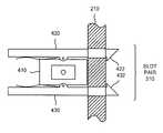
- FIG. 3is an exemplary diagram of a front view of connection plate 210 .
- Connection plate 210may be formed of a rigid material, such as plastic or metal.
- Connection plate 210may include a number of slot pairs 310 .
- Each slot pair 310may include a pair of through-holes that may facilitate seating of fiber connectors 220 . While a particular number and arrangement of slot pairs 310 are shown in FIG. 3 , the number and arrangement of slot pairs 310 may differ in other implementations.
- fiber connectors 220may be seated on connection plate 210 . Each fiber connector 220 may mate two optical fibers in a vertical direction. As shown in FIG. 2 , in one implementation, a fiber connector 220 may receive an optical fiber from a top side of connection plate 210 and may receive an optical fiber from a bottom side of connection plate 210 .
- FIGS. 4A and 4Bare exemplary diagrams of a fiber connector 220 .
- FIG. 4Ashows fiber connector 220 from a disassembled state
- FIG. 4Bshows fiber connector 220 in an assembled state. While FIGS. 4A and 4B show a particular architecture for fiber connector 220 , fiber connector 220 may include a different arrangement of elements in another implementation.
- fiber connector 220may include connector housing 410 and handlers 420 and 430 .
- Connector housing 410 and handlers 420 and 430may be formed of at least a semi-rigid material, such as plastic or rubber.
- Connector housing 410may include a port 412 to receive an optical fiber.
- Connector housing 410may include a corresponding port (not shown in FIG. 4A ) on the opposite side of connector housing 410 to receive another optical fiber.
- the pair of portsmay be used to connect (mate) two optical fibers together.
- Connector housing 410may also include a pair of pin holes 414 and 416 .
- Each of pin holes 414 and 416may include a hole that is capable of receiving a joint pin or the like.
- Handler 420may include a tip 422 , a spring 424 , and a pin hole 426 .
- Tip 422may be shaped to be inserted into a slot of a slot pair 310 of connection plate 210 and securely hold fiber connector 220 against connection plate 210 if fiber connector 220 is seated.
- tip 422may include an angular protrusion portion. In another implementation, tip 422 may be differently shaped.
- Spring 424may include a flexible, elastic material that is capable of storing mechanical energy.
- Pin hole 426may include a hole that is shaped to mate with pin hole 414 of connector housing 410 .
- Pin holes 414 and 426may be fastened together via a joint pin or the like.
- the joint pinmay rotatably connect handler 420 to connector housing 410 .
- Handler 430may include a tip 432 , a spring 434 , and a pin hole 436 .
- Tip 432may be shaped to be inserted into a slot of a slot pair 310 of connection plate 210 and securely hold fiber connector 220 against connection plate 210 when fiber connector 220 is seated.
- tip 432may include an angular protrusion portion. In another implementation, tip 432 may be differently shaped.
- Spring 434may include a flexible, elastic material that is capable of storing mechanical energy.
- Pin hole 436may include a hole that is shaped to mate with pin hole 416 of connector housing 410 .
- Pin holes 416 and 436may be fastened together via a joint pin or the like.
- the joint pinmay rotatably connect handler 430 to connector housing 410 .
- springs 424 and 434may exert a force against connector housing 410 to push the left hand side of fiber connector 220 outward and the right hand side of fiber connector 220 inward, similar to a wooden clothespin.
- the terms “left hand side” and “right hand side”are intended to be relative to the orientation of fiber connector 220 shown in the figures.
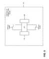
- FIG. 5is an exemplary diagram of a front view of fiber connector 220 .
- the front viewshows the manner in which fiber connector 220 may be positioned if seated on connection plate 210 .
- two optical fibersmay connect to connector housing 410 in a vertical direction.
- fiber connector 220may have a low profile if seated on connection plate 210 .
- no such bendingoccurs in a vertical connection.
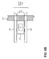
- FIGS. 6A and 6Bare exemplary diagrams illustrating the seating of fiber connector 220 on connection plate 210 .
- a usermay press the left hand side of handlers 420 and 430 together. This may cause the right hand side of handlers 420 and 430 to separate. The user may then insert the right hand side of handlers 420 and 430 into a slot pair 310 of connection plate 210 .
- the usermay insert the right hand side of handlers 420 and 430 until tips 422 and 432 fully pass through connection plate 210 .
- the usermay then release the left hand side of handlers 420 and 430 .
- Springs 424 and 434may exert a force against connector housing 410 to push the left hand side of fiber connector 220 outward and the right hand side of fiber connector 220 inward, thereby securely seating fiber connector 220 to connection plate 210 via the through-holes of slot pair 310 .
- the angular protrusion portions of tips 422 and 432may prevent fiber connector 220 from becoming unseated from connection plate 210 .
- Fiber connector 220may, thus, permit easy access to the optical fibers and permit both ends of the optical fibers to be cleaned. For example, a user may simply press the left hand side of handlers 420 and 430 together. This may cause the right hand side of handlers 420 and 430 to separate. The user may then remove the right hand side of handlers 420 and 430 from a slot pair 310 of connection plate 210 without disturbing any of the other fiber connectors 220 . The user may then remove the optical fibers from connector housing 410 and clean them. The user may re-insert the cleaned optical fibers into connector housing 410 and re-seat fiber connector 220 to connection plate 210 , as described above.
- FIG. 7is an exemplary diagram of a scaleable fiber patch panel system 700 .
- Fiber patch panel system 700may include a housing 110 that includes a door 112 and a number of slots 118 , as described above with regard to fiber patch panel system 100 of FIG. 1 .
- fiber patch panel system 700may include a number of patch panels 710 - 1 , 710 - 2 , . . . , 710 -N (where N>1) (collectively referred to as “patch panels 710 ”).
- Each of patch panels 710may be similar to patch panel 120 .
- each of patch panels 710may include a connection plate 210 and a set of fiber connectors 220 .
- Patch panels 710may be rotatably connected to housing 110 via a set of hinges 720 .
- a hinge 720may include any mechanical mechanism that permits a patch panel 710 to fixedly attach to housing 110 while permitting patch panel 710 to rotate toward door 112 (“open position”) and/or away from door 112 (“closed position”).
- patch panel 710 - 1may rotate outwards (toward door 112 ) exposing patch panel 710 - 2 ;
- patch panel 710 - 2may rotate outwards exposing patch panel 710 - 3 ; and so forth.
- Each of patch panels 710may include a mechanism to permit a user to grab and rotate patch panel 710 , such as a handle, an opening, or the like.
- the last patch paneli.e., patch panel 710 -N
- Patch panels 710 and/or housing 110may include a stabilizing mechanism 730 (e.g., one or more stoppers and/or magnets) to secure patch panels 710 at the closed position within housing 110 .
- a stabilizing mechanism 730e.g., one or more stoppers and/or magnets
- the last patch paneli.e., patch panel 710 -N
- Fiber patch panel system 700may be scaleable in the sense that as many layers of patch panels 710 may be included within housing 110 as needed. Each additional patch panel 710 may add a number of fiber connectors 220 and, thus, a number of potential fiber optic connections.
- FIG. 8is an exemplary diagram of a fiber patch panel system 800 that includes a splice tray or drawer (referred to as a “splice tray/drawer” 810 ).
- Fiber patch panel system 800may include housing 110 and patch panel 120 / 710 , as described above with regard to fiber patch panel system 100 of FIG. 1 or fiber patch panel system 700 of FIG. 7 .
- patch panel 120 / 710may occupy a vertical space less than the vertical space of housing 110 to leave an area for splice tray/drawer 810 .
- Splice tray/drawer 810may be used to hold one or more pairs of spliced fibers.
- Splice tray/drawer 810may be inserted into housing 110 to reside on a bottom (or floor) of housing 110 . This may make it easy to install and remove splice tray/drawer 810 as necessary. In another implementation, multiple splice trays or drawers 810 may be used within the bottom area of housing 110 .
- Implementations described hereinmay provide an arrangement for a fiber patch panel system that conserves horizontal space, is scaleable, manages fiber bending, provides easy access to optical fibers for insertion, removal, and/or cleaning, and/or permits easy installation and removal of a splice tray or drawer.
Landscapes
- Physics & Mathematics (AREA)
- General Physics & Mathematics (AREA)
- Optics & Photonics (AREA)
- Light Guides In General And Applications Therefor (AREA)
- Mechanical Coupling Of Light Guides (AREA)
Abstract
Description
Claims (12)
Priority Applications (2)
| Application Number | Priority Date | Filing Date | Title |
|---|---|---|---|
| US11/748,737US7676135B2 (en) | 2007-05-15 | 2007-05-15 | Fiber patch panel |
| US12/634,318US7927024B2 (en) | 2007-05-15 | 2009-12-09 | Fiber patch panel |
Applications Claiming Priority (1)
| Application Number | Priority Date | Filing Date | Title |
|---|---|---|---|
| US11/748,737US7676135B2 (en) | 2007-05-15 | 2007-05-15 | Fiber patch panel |
Related Child Applications (1)
| Application Number | Title | Priority Date | Filing Date |
|---|---|---|---|
| US12/634,318ContinuationUS7927024B2 (en) | 2007-05-15 | 2009-12-09 | Fiber patch panel |
Publications (2)
| Publication Number | Publication Date |
|---|---|
| US20080285932A1 US20080285932A1 (en) | 2008-11-20 |
| US7676135B2true US7676135B2 (en) | 2010-03-09 |
Family
ID=40027580
Family Applications (2)
| Application Number | Title | Priority Date | Filing Date |
|---|---|---|---|
| US11/748,737Expired - Fee RelatedUS7676135B2 (en) | 2007-05-15 | 2007-05-15 | Fiber patch panel |
| US12/634,318Expired - Fee RelatedUS7927024B2 (en) | 2007-05-15 | 2009-12-09 | Fiber patch panel |
Family Applications After (1)
| Application Number | Title | Priority Date | Filing Date |
|---|---|---|---|
| US12/634,318Expired - Fee RelatedUS7927024B2 (en) | 2007-05-15 | 2009-12-09 | Fiber patch panel |
Country Status (1)
| Country | Link |
|---|---|
| US (2) | US7676135B2 (en) |
Cited By (37)
| Publication number | Priority date | Publication date | Assignee | Title |
|---|---|---|---|---|
| US20100166378A1 (en)* | 2008-09-05 | 2010-07-01 | Chris Taylor | Panel mount |
| US7856166B2 (en) | 2008-09-02 | 2010-12-21 | Corning Cable Systems Llc | High-density patch-panel assemblies for optical fiber telecommunications |
| US8433171B2 (en) | 2009-06-19 | 2013-04-30 | Corning Cable Systems Llc | High fiber optic cable packing density apparatus |
| US8538226B2 (en) | 2009-05-21 | 2013-09-17 | Corning Cable Systems Llc | Fiber optic equipment guides and rails configured with stopping position(s), and related equipment and methods |
| US8542973B2 (en) | 2010-04-23 | 2013-09-24 | Ccs Technology, Inc. | Fiber optic distribution device |
| US8593828B2 (en) | 2010-02-04 | 2013-11-26 | Corning Cable Systems Llc | Communications equipment housings, assemblies, and related alignment features and methods |
| US8625950B2 (en) | 2009-12-18 | 2014-01-07 | Corning Cable Systems Llc | Rotary locking apparatus for fiber optic equipment trays and related methods |
| US8660397B2 (en) | 2010-04-30 | 2014-02-25 | Corning Cable Systems Llc | Multi-layer module |
| US8662760B2 (en) | 2010-10-29 | 2014-03-04 | Corning Cable Systems Llc | Fiber optic connector employing optical fiber guide member |
| US8699838B2 (en) | 2009-05-14 | 2014-04-15 | Ccs Technology, Inc. | Fiber optic furcation module |
| US8705926B2 (en) | 2010-04-30 | 2014-04-22 | Corning Optical Communications LLC | Fiber optic housings having a removable top, and related components and methods |
| US8712206B2 (en) | 2009-06-19 | 2014-04-29 | Corning Cable Systems Llc | High-density fiber optic modules and module housings and related equipment |
| US8718436B2 (en) | 2010-08-30 | 2014-05-06 | Corning Cable Systems Llc | Methods, apparatuses for providing secure fiber optic connections |
| US8879881B2 (en) | 2010-04-30 | 2014-11-04 | Corning Cable Systems Llc | Rotatable routing guide and assembly |
| US8913866B2 (en) | 2010-03-26 | 2014-12-16 | Corning Cable Systems Llc | Movable adapter panel |
| US8953924B2 (en) | 2011-09-02 | 2015-02-10 | Corning Cable Systems Llc | Removable strain relief brackets for securing fiber optic cables and/or optical fibers to fiber optic equipment, and related assemblies and methods |
| US8989547B2 (en) | 2011-06-30 | 2015-03-24 | Corning Cable Systems Llc | Fiber optic equipment assemblies employing non-U-width-sized housings and related methods |
| US8985862B2 (en) | 2013-02-28 | 2015-03-24 | Corning Cable Systems Llc | High-density multi-fiber adapter housings |
| US8995812B2 (en) | 2012-10-26 | 2015-03-31 | Ccs Technology, Inc. | Fiber optic management unit and fiber optic distribution device |
| US9008485B2 (en) | 2011-05-09 | 2015-04-14 | Corning Cable Systems Llc | Attachment mechanisms employed to attach a rear housing section to a fiber optic housing, and related assemblies and methods |
| US9020320B2 (en) | 2008-08-29 | 2015-04-28 | Corning Cable Systems Llc | High density and bandwidth fiber optic apparatuses and related equipment and methods |
| US9022814B2 (en) | 2010-04-16 | 2015-05-05 | Ccs Technology, Inc. | Sealing and strain relief device for data cables |
| US9038832B2 (en) | 2011-11-30 | 2015-05-26 | Corning Cable Systems Llc | Adapter panel support assembly |
| US9042702B2 (en) | 2012-09-18 | 2015-05-26 | Corning Cable Systems Llc | Platforms and systems for fiber optic cable attachment |
| US9059578B2 (en) | 2009-02-24 | 2015-06-16 | Ccs Technology, Inc. | Holding device for a cable or an assembly for use with a cable |
| US9075217B2 (en) | 2010-04-30 | 2015-07-07 | Corning Cable Systems Llc | Apparatuses and related components and methods for expanding capacity of fiber optic housings |
| US9075216B2 (en) | 2009-05-21 | 2015-07-07 | Corning Cable Systems Llc | Fiber optic housings configured to accommodate fiber optic modules/cassettes and fiber optic panels, and related components and methods |
| US9116324B2 (en) | 2010-10-29 | 2015-08-25 | Corning Cable Systems Llc | Stacked fiber optic modules and fiber optic equipment configured to support stacked fiber optic modules |
| US9213161B2 (en) | 2010-11-05 | 2015-12-15 | Corning Cable Systems Llc | Fiber body holder and strain relief device |
| US9250409B2 (en) | 2012-07-02 | 2016-02-02 | Corning Cable Systems Llc | Fiber-optic-module trays and drawers for fiber-optic equipment |
| US9279951B2 (en) | 2010-10-27 | 2016-03-08 | Corning Cable Systems Llc | Fiber optic module for limited space applications having a partially sealed module sub-assembly |
| US9519118B2 (en) | 2010-04-30 | 2016-12-13 | Corning Optical Communications LLC | Removable fiber management sections for fiber optic housings, and related components and methods |
| US9632270B2 (en) | 2010-04-30 | 2017-04-25 | Corning Optical Communications LLC | Fiber optic housings configured for tool-less assembly, and related components and methods |
| US9645317B2 (en) | 2011-02-02 | 2017-05-09 | Corning Optical Communications LLC | Optical backplane extension modules, and related assemblies suitable for establishing optical connections to information processing modules disposed in equipment racks |
| US9720195B2 (en) | 2010-04-30 | 2017-08-01 | Corning Optical Communications LLC | Apparatuses and related components and methods for attachment and release of fiber optic housings to and from an equipment rack |
| US10094996B2 (en) | 2008-08-29 | 2018-10-09 | Corning Optical Communications, Llc | Independently translatable modules and fiber optic equipment trays in fiber optic equipment |
| US11294136B2 (en) | 2008-08-29 | 2022-04-05 | Corning Optical Communications LLC | High density and bandwidth fiber optic apparatuses and related equipment and methods |
Citations (3)
| Publication number | Priority date | Publication date | Assignee | Title |
|---|---|---|---|---|
| US20010036351A1 (en)* | 2000-03-08 | 2001-11-01 | Fritz Robert L. | Fiber optic wall mount cabinet |
| US20040175089A1 (en)* | 2003-03-05 | 2004-09-09 | Dagley Mark R. | High density fiber optic distribution frame |
| US6909833B2 (en)* | 2002-03-15 | 2005-06-21 | Fiber Optic Network Solutions, Inc. | Optical fiber enclosure system using integrated optical connector and coupler assembly |
- 2007
- 2007-05-15USUS11/748,737patent/US7676135B2/ennot_activeExpired - Fee Related
- 2009
- 2009-12-09USUS12/634,318patent/US7927024B2/ennot_activeExpired - Fee Related
Patent Citations (3)
| Publication number | Priority date | Publication date | Assignee | Title |
|---|---|---|---|---|
| US20010036351A1 (en)* | 2000-03-08 | 2001-11-01 | Fritz Robert L. | Fiber optic wall mount cabinet |
| US6909833B2 (en)* | 2002-03-15 | 2005-06-21 | Fiber Optic Network Solutions, Inc. | Optical fiber enclosure system using integrated optical connector and coupler assembly |
| US20040175089A1 (en)* | 2003-03-05 | 2004-09-09 | Dagley Mark R. | High density fiber optic distribution frame |
Cited By (59)
| Publication number | Priority date | Publication date | Assignee | Title |
|---|---|---|---|---|
| US10459184B2 (en) | 2008-08-29 | 2019-10-29 | Corning Optical Communications LLC | High density and bandwidth fiber optic apparatuses and related equipment and methods |
| US11092767B2 (en) | 2008-08-29 | 2021-08-17 | Corning Optical Communications LLC | High density and bandwidth fiber optic apparatuses and related equipment and methods |
| US10094996B2 (en) | 2008-08-29 | 2018-10-09 | Corning Optical Communications, Llc | Independently translatable modules and fiber optic equipment trays in fiber optic equipment |
| US10120153B2 (en) | 2008-08-29 | 2018-11-06 | Corning Optical Communications, Llc | Independently translatable modules and fiber optic equipment trays in fiber optic equipment |
| US10126514B2 (en) | 2008-08-29 | 2018-11-13 | Corning Optical Communications, Llc | Independently translatable modules and fiber optic equipment trays in fiber optic equipment |
| US11086089B2 (en) | 2008-08-29 | 2021-08-10 | Corning Optical Communications LLC | High density and bandwidth fiber optic apparatuses and related equipment and methods |
| US10222570B2 (en) | 2008-08-29 | 2019-03-05 | Corning Optical Communications LLC | Independently translatable modules and fiber optic equipment trays in fiber optic equipment |
| US10416405B2 (en) | 2008-08-29 | 2019-09-17 | Corning Optical Communications LLC | Independently translatable modules and fiber optic equipment trays in fiber optic equipment |
| US10422971B2 (en) | 2008-08-29 | 2019-09-24 | Corning Optical Communicatinos LLC | High density and bandwidth fiber optic apparatuses and related equipment and methods |
| US10444456B2 (en) | 2008-08-29 | 2019-10-15 | Corning Optical Communications LLC | High density and bandwidth fiber optic apparatuses and related equipment and methods |
| US12072545B2 (en) | 2008-08-29 | 2024-08-27 | Corning Optical Communications LLC | High density and bandwidth fiber optic apparatuses and related equipment and methods |
| US11754796B2 (en) | 2008-08-29 | 2023-09-12 | Corning Optical Communications LLC | Independently translatable modules and fiber optic equipment trays in fiber optic equipment |
| US9910236B2 (en) | 2008-08-29 | 2018-03-06 | Corning Optical Communications LLC | High density and bandwidth fiber optic apparatuses and related equipment and methods |
| US10564378B2 (en) | 2008-08-29 | 2020-02-18 | Corning Optical Communications LLC | High density and bandwidth fiber optic apparatuses and related equipment and methods |
| US9020320B2 (en) | 2008-08-29 | 2015-04-28 | Corning Cable Systems Llc | High density and bandwidth fiber optic apparatuses and related equipment and methods |
| US11609396B2 (en) | 2008-08-29 | 2023-03-21 | Corning Optical Communications LLC | High density and bandwidth fiber optic apparatuses and related equipment and methods |
| US11294135B2 (en) | 2008-08-29 | 2022-04-05 | Corning Optical Communications LLC | High density and bandwidth fiber optic apparatuses and related equipment and methods |
| US10606014B2 (en) | 2008-08-29 | 2020-03-31 | Corning Optical Communications LLC | Independently translatable modules and fiber optic equipment trays in fiber optic equipment |
| US10852499B2 (en) | 2008-08-29 | 2020-12-01 | Corning Optical Communications LLC | High density and bandwidth fiber optic apparatuses and related equipment and methods |
| US11294136B2 (en) | 2008-08-29 | 2022-04-05 | Corning Optical Communications LLC | High density and bandwidth fiber optic apparatuses and related equipment and methods |
| US20110085776A1 (en)* | 2008-09-02 | 2011-04-14 | Eric Biribuze | High-Density Patch-Panel Assemblies for Optical Fiber Telecommunications |
| US7856166B2 (en) | 2008-09-02 | 2010-12-21 | Corning Cable Systems Llc | High-density patch-panel assemblies for optical fiber telecommunications |
| US8331752B2 (en) | 2008-09-02 | 2012-12-11 | Corning Cable Systems Llc | High-density patch-panel assemblies for optical fiber telecommunications |
| US8351753B2 (en)* | 2008-09-05 | 2013-01-08 | Adc Gmbh | Panel mount |
| US20100166378A1 (en)* | 2008-09-05 | 2010-07-01 | Chris Taylor | Panel mount |
| US9059578B2 (en) | 2009-02-24 | 2015-06-16 | Ccs Technology, Inc. | Holding device for a cable or an assembly for use with a cable |
| US8699838B2 (en) | 2009-05-14 | 2014-04-15 | Ccs Technology, Inc. | Fiber optic furcation module |
| US8538226B2 (en) | 2009-05-21 | 2013-09-17 | Corning Cable Systems Llc | Fiber optic equipment guides and rails configured with stopping position(s), and related equipment and methods |
| US9075216B2 (en) | 2009-05-21 | 2015-07-07 | Corning Cable Systems Llc | Fiber optic housings configured to accommodate fiber optic modules/cassettes and fiber optic panels, and related components and methods |
| US8712206B2 (en) | 2009-06-19 | 2014-04-29 | Corning Cable Systems Llc | High-density fiber optic modules and module housings and related equipment |
| US8433171B2 (en) | 2009-06-19 | 2013-04-30 | Corning Cable Systems Llc | High fiber optic cable packing density apparatus |
| US8625950B2 (en) | 2009-12-18 | 2014-01-07 | Corning Cable Systems Llc | Rotary locking apparatus for fiber optic equipment trays and related methods |
| US8593828B2 (en) | 2010-02-04 | 2013-11-26 | Corning Cable Systems Llc | Communications equipment housings, assemblies, and related alignment features and methods |
| US8992099B2 (en) | 2010-02-04 | 2015-03-31 | Corning Cable Systems Llc | Optical interface cards, assemblies, and related methods, suited for installation and use in antenna system equipment |
| US8913866B2 (en) | 2010-03-26 | 2014-12-16 | Corning Cable Systems Llc | Movable adapter panel |
| US9022814B2 (en) | 2010-04-16 | 2015-05-05 | Ccs Technology, Inc. | Sealing and strain relief device for data cables |
| US8542973B2 (en) | 2010-04-23 | 2013-09-24 | Ccs Technology, Inc. | Fiber optic distribution device |
| US8705926B2 (en) | 2010-04-30 | 2014-04-22 | Corning Optical Communications LLC | Fiber optic housings having a removable top, and related components and methods |
| US9075217B2 (en) | 2010-04-30 | 2015-07-07 | Corning Cable Systems Llc | Apparatuses and related components and methods for expanding capacity of fiber optic housings |
| US8879881B2 (en) | 2010-04-30 | 2014-11-04 | Corning Cable Systems Llc | Rotatable routing guide and assembly |
| US9632270B2 (en) | 2010-04-30 | 2017-04-25 | Corning Optical Communications LLC | Fiber optic housings configured for tool-less assembly, and related components and methods |
| US9519118B2 (en) | 2010-04-30 | 2016-12-13 | Corning Optical Communications LLC | Removable fiber management sections for fiber optic housings, and related components and methods |
| US8660397B2 (en) | 2010-04-30 | 2014-02-25 | Corning Cable Systems Llc | Multi-layer module |
| US9720195B2 (en) | 2010-04-30 | 2017-08-01 | Corning Optical Communications LLC | Apparatuses and related components and methods for attachment and release of fiber optic housings to and from an equipment rack |
| US8718436B2 (en) | 2010-08-30 | 2014-05-06 | Corning Cable Systems Llc | Methods, apparatuses for providing secure fiber optic connections |
| US9279951B2 (en) | 2010-10-27 | 2016-03-08 | Corning Cable Systems Llc | Fiber optic module for limited space applications having a partially sealed module sub-assembly |
| US8662760B2 (en) | 2010-10-29 | 2014-03-04 | Corning Cable Systems Llc | Fiber optic connector employing optical fiber guide member |
| US9116324B2 (en) | 2010-10-29 | 2015-08-25 | Corning Cable Systems Llc | Stacked fiber optic modules and fiber optic equipment configured to support stacked fiber optic modules |
| US9213161B2 (en) | 2010-11-05 | 2015-12-15 | Corning Cable Systems Llc | Fiber body holder and strain relief device |
| US10481335B2 (en) | 2011-02-02 | 2019-11-19 | Corning Optical Communications, Llc | Dense shuttered fiber optic connectors and assemblies suitable for establishing optical connections for optical backplanes in equipment racks |
| US9645317B2 (en) | 2011-02-02 | 2017-05-09 | Corning Optical Communications LLC | Optical backplane extension modules, and related assemblies suitable for establishing optical connections to information processing modules disposed in equipment racks |
| US9008485B2 (en) | 2011-05-09 | 2015-04-14 | Corning Cable Systems Llc | Attachment mechanisms employed to attach a rear housing section to a fiber optic housing, and related assemblies and methods |
| US8989547B2 (en) | 2011-06-30 | 2015-03-24 | Corning Cable Systems Llc | Fiber optic equipment assemblies employing non-U-width-sized housings and related methods |
| US8953924B2 (en) | 2011-09-02 | 2015-02-10 | Corning Cable Systems Llc | Removable strain relief brackets for securing fiber optic cables and/or optical fibers to fiber optic equipment, and related assemblies and methods |
| US9038832B2 (en) | 2011-11-30 | 2015-05-26 | Corning Cable Systems Llc | Adapter panel support assembly |
| US9250409B2 (en) | 2012-07-02 | 2016-02-02 | Corning Cable Systems Llc | Fiber-optic-module trays and drawers for fiber-optic equipment |
| US9042702B2 (en) | 2012-09-18 | 2015-05-26 | Corning Cable Systems Llc | Platforms and systems for fiber optic cable attachment |
| US8995812B2 (en) | 2012-10-26 | 2015-03-31 | Ccs Technology, Inc. | Fiber optic management unit and fiber optic distribution device |
| US8985862B2 (en) | 2013-02-28 | 2015-03-24 | Corning Cable Systems Llc | High-density multi-fiber adapter housings |
Also Published As
| Publication number | Publication date |
|---|---|
| US7927024B2 (en) | 2011-04-19 |
| US20100086259A1 (en) | 2010-04-08 |
| US20080285932A1 (en) | 2008-11-20 |
Similar Documents
| Publication | Publication Date | Title |
|---|---|---|
| US7676135B2 (en) | Fiber patch panel | |
| US8104973B2 (en) | Ferrule-to-ferrule adapter and ferrule adapter assembly | |
| US7296935B1 (en) | Ferrule adapter and ferrule adapter assembly | |
| EP2333597B1 (en) | Fiber optic module assembly and associated methods | |
| US6944387B2 (en) | Fiber optic connector tray system | |
| US6674952B2 (en) | Fiber optic cable bend radius protection system | |
| US20110129186A1 (en) | Fiber Optic Module Assembly and Associated Methods | |
| US10725248B2 (en) | Fiber optic receptacle with integrated device therein incorporating a behind-the-wall fiber optic receptacle | |
| CA2602501C (en) | Slack limiting fiber management system for an optic fiber distribution hub | |
| US6327139B1 (en) | Electrical equipment rack having cable management arms with flexible linkage | |
| US20090080849A1 (en) | Blank plate for managing cables | |
| JPH10502188A (en) | Fiber optic housing with few parts | |
| US20100207498A1 (en) | Fiber management shelf having removable door | |
| MX2007011251A (en) | Distribution module for an optic fiber distribution hub. | |
| US20150241650A1 (en) | Internal shutter mechanism for a ganged fiber optic adapter | |
| CN102549467A (en) | Fiber management component | |
| US20120211447A1 (en) | Communication Shelf Having Supports for Pivotable Adapter Panels and Method of Mounting Adapter Panels Therein | |
| US12298574B2 (en) | Optical fiber management system | |
| CN103460095B (en) | Fiber Optic Adapter Base | |
| US9075220B2 (en) | Optical fiber module with mounting block for securing an optical fiber connector | |
| US20120189261A1 (en) | Connector module for telecommunication patch panels | |
| US6427936B1 (en) | Optical fiber cable management apparatus | |
| US8554042B2 (en) | Optical fiber management shelf including door with push-push fastener | |
| US20200386967A1 (en) | Cassette assembly for a plural of fiber optic receptacles | |
| US8953919B2 (en) | Datacommunications modules, cable-connector assemblies and components therefor |
Legal Events
| Date | Code | Title | Description |
|---|---|---|---|
| AS | Assignment | Owner name:VERIZON SERVICES ORGANIZATION INC., TEXAS Free format text:ASSIGNMENT OF ASSIGNORS INTEREST;ASSIGNOR:CHEN, DAVID Z.;REEL/FRAME:019296/0210 Effective date:20070515 Owner name:VERIZON SERVICES ORGANIZATION INC.,TEXAS Free format text:ASSIGNMENT OF ASSIGNORS INTEREST;ASSIGNOR:CHEN, DAVID Z.;REEL/FRAME:019296/0210 Effective date:20070515 | |
| AS | Assignment | Owner name:VERIZON PATENT AND LICENSING INC., NEW JERSEY Free format text:ASSIGNMENT OF ASSIGNORS INTEREST;ASSIGNOR:VERIZON SERVICES ORGANIZATION INC.;REEL/FRAME:023235/0374 Effective date:20090801 Owner name:VERIZON PATENT AND LICENSING INC.,NEW JERSEY Free format text:ASSIGNMENT OF ASSIGNORS INTEREST;ASSIGNOR:VERIZON SERVICES ORGANIZATION INC.;REEL/FRAME:023235/0374 Effective date:20090801 | |
| FPAY | Fee payment | Year of fee payment:4 | |
| FEPP | Fee payment procedure | Free format text:MAINTENANCE FEE REMINDER MAILED (ORIGINAL EVENT CODE: REM.) | |
| LAPS | Lapse for failure to pay maintenance fees | Free format text:PATENT EXPIRED FOR FAILURE TO PAY MAINTENANCE FEES (ORIGINAL EVENT CODE: EXP.) | |
| STCH | Information on status: patent discontinuation | Free format text:PATENT EXPIRED DUE TO NONPAYMENT OF MAINTENANCE FEES UNDER 37 CFR 1.362 | |
| FP | Lapsed due to failure to pay maintenance fee | Effective date:20180309 |