US7676007B1 - System and method for interpolation based transmit beamforming for MIMO-OFDM with partial feedback - Google Patents
System and method for interpolation based transmit beamforming for MIMO-OFDM with partial feedbackDownload PDFInfo
- Publication number
- US7676007B1 US7676007B1US11/188,233US18823305AUS7676007B1US 7676007 B1US7676007 B1US 7676007B1US 18823305 AUS18823305 AUS 18823305AUS 7676007 B1US7676007 B1US 7676007B1
- Authority
- US
- United States
- Prior art keywords
- communication apparatus
- subcarriers
- transmitter
- interpolation
- receiver
- Prior art date
- Legal status (The legal status is an assumption and is not a legal conclusion. Google has not performed a legal analysis and makes no representation as to the accuracy of the status listed.)
- Active, expires
Links
Images


Classifications
- H—ELECTRICITY
- H04—ELECTRIC COMMUNICATION TECHNIQUE
- H04B—TRANSMISSION
- H04B7/00—Radio transmission systems, i.e. using radiation field
- H04B7/02—Diversity systems; Multi-antenna system, i.e. transmission or reception using multiple antennas
- H04B7/04—Diversity systems; Multi-antenna system, i.e. transmission or reception using multiple antennas using two or more spaced independent antennas
- H04B7/06—Diversity systems; Multi-antenna system, i.e. transmission or reception using multiple antennas using two or more spaced independent antennas at the transmitting station
- H04B7/0613—Diversity systems; Multi-antenna system, i.e. transmission or reception using multiple antennas using two or more spaced independent antennas at the transmitting station using simultaneous transmission
- H04B7/0615—Diversity systems; Multi-antenna system, i.e. transmission or reception using multiple antennas using two or more spaced independent antennas at the transmitting station using simultaneous transmission of weighted versions of same signal
- H04B7/0617—Diversity systems; Multi-antenna system, i.e. transmission or reception using multiple antennas using two or more spaced independent antennas at the transmitting station using simultaneous transmission of weighted versions of same signal for beam forming
- H—ELECTRICITY
- H04—ELECTRIC COMMUNICATION TECHNIQUE
- H04B—TRANSMISSION
- H04B7/00—Radio transmission systems, i.e. using radiation field
- H04B7/02—Diversity systems; Multi-antenna system, i.e. transmission or reception using multiple antennas
- H04B7/04—Diversity systems; Multi-antenna system, i.e. transmission or reception using multiple antennas using two or more spaced independent antennas
- H04B7/06—Diversity systems; Multi-antenna system, i.e. transmission or reception using multiple antennas using two or more spaced independent antennas at the transmitting station
- H04B7/0613—Diversity systems; Multi-antenna system, i.e. transmission or reception using multiple antennas using two or more spaced independent antennas at the transmitting station using simultaneous transmission
- H04B7/0615—Diversity systems; Multi-antenna system, i.e. transmission or reception using multiple antennas using two or more spaced independent antennas at the transmitting station using simultaneous transmission of weighted versions of same signal
- H04B7/0619—Diversity systems; Multi-antenna system, i.e. transmission or reception using multiple antennas using two or more spaced independent antennas at the transmitting station using simultaneous transmission of weighted versions of same signal using feedback from receiving side
- H04B7/0621—Feedback content
- H04B7/0634—Antenna weights or vector/matrix coefficients
- H—ELECTRICITY
- H04—ELECTRIC COMMUNICATION TECHNIQUE
- H04B—TRANSMISSION
- H04B7/00—Radio transmission systems, i.e. using radiation field
- H04B7/02—Diversity systems; Multi-antenna system, i.e. transmission or reception using multiple antennas
- H04B7/04—Diversity systems; Multi-antenna system, i.e. transmission or reception using multiple antennas using two or more spaced independent antennas
- H04B7/06—Diversity systems; Multi-antenna system, i.e. transmission or reception using multiple antennas using two or more spaced independent antennas at the transmitting station
- H04B7/0613—Diversity systems; Multi-antenna system, i.e. transmission or reception using multiple antennas using two or more spaced independent antennas at the transmitting station using simultaneous transmission
- H04B7/0615—Diversity systems; Multi-antenna system, i.e. transmission or reception using multiple antennas using two or more spaced independent antennas at the transmitting station using simultaneous transmission of weighted versions of same signal
- H04B7/0619—Diversity systems; Multi-antenna system, i.e. transmission or reception using multiple antennas using two or more spaced independent antennas at the transmitting station using simultaneous transmission of weighted versions of same signal using feedback from receiving side
- H04B7/0658—Feedback reduction
- H04B7/066—Combined feedback for a number of channels, e.g. over several subcarriers like in orthogonal frequency division multiplexing [OFDM]
- H—ELECTRICITY
- H04—ELECTRIC COMMUNICATION TECHNIQUE
- H04L—TRANSMISSION OF DIGITAL INFORMATION, e.g. TELEGRAPHIC COMMUNICATION
- H04L5/00—Arrangements affording multiple use of the transmission path
- H04L5/0001—Arrangements for dividing the transmission path
- H04L5/0028—Variable division
- H—ELECTRICITY
- H04—ELECTRIC COMMUNICATION TECHNIQUE
- H04L—TRANSMISSION OF DIGITAL INFORMATION, e.g. TELEGRAPHIC COMMUNICATION
- H04L5/00—Arrangements affording multiple use of the transmission path
- H04L5/0001—Arrangements for dividing the transmission path
- H04L5/0003—Two-dimensional division
- H04L5/0005—Time-frequency
- H04L5/0007—Time-frequency the frequencies being orthogonal, e.g. OFDM(A) or DMT
- H—ELECTRICITY
- H04—ELECTRIC COMMUNICATION TECHNIQUE
- H04L—TRANSMISSION OF DIGITAL INFORMATION, e.g. TELEGRAPHIC COMMUNICATION
- H04L5/00—Arrangements affording multiple use of the transmission path
- H04L5/0001—Arrangements for dividing the transmission path
- H04L5/0014—Three-dimensional division
- H04L5/0023—Time-frequency-space
- H—ELECTRICITY
- H04—ELECTRIC COMMUNICATION TECHNIQUE
- H04L—TRANSMISSION OF DIGITAL INFORMATION, e.g. TELEGRAPHIC COMMUNICATION
- H04L5/00—Arrangements affording multiple use of the transmission path
- H04L5/003—Arrangements for allocating sub-channels of the transmission path
- H04L5/0058—Allocation criteria
- H04L5/006—Quality of the received signal, e.g. BER, SNR, water filling
Definitions
- This applicationrelates to a multiple input multiple output system using orthogonal frequency division multiplexing, and more particularly, to systems using partial feedback for interpolation based transmit beamforming.
- MIMO systemsinclude multiple transmit antennas and multiple receive antennas.
- MIMO systemsprovide improved reliability over fading channels, because the increased dimension of a MIMO system may be used to mitigate signal-level fluctuations.
- Transmit beamforming with receive combiningis a method to exploit the diversity offered by MIMO systems.
- the beamforming techniques for narrowband channelsmay be extended to frequency selective MIMO channels by employing orthogonal frequency division multiplexing (OFDM).
- OFDMorthogonal frequency division multiplexing
- the use of MIMO technology in combination with OFDMe.g., “MIMO-OFDM,” converts a broadband MIMO channel into multiple narrowband MIMO channels corresponding to OFDM subcarriers.
- a communication systemcomprises a transmitter and a receiver.
- the transmitterprovides orthogonal frequency division multiplexing to a plurality of first signals and provides the signals on a plurality of subcarriers.
- the transmitterincludes a interpolator.
- the receiverreceives the signals outputted from the transmitter and provides decoded signals indicative of the first signals, and provides beamforming vectors and interpolation parameters.
- the interpolatorprovides beamforming vectors in response to the beamforming vectors and interpolation parameters from the receiver.
- the interpolatoruses a phase rotation on the beamforming vectors.
- the phase rotationreduces distortion in the interpolation of the beamforming vectors.
- the phase rotationsatisfies a closed-form solution.
- the interpolatorquantizes the vectors using a code book.
- the receiversubsamples the subcarriers, selects a portion of said subcarriers, evaluates the beamforming vectors corresponding to said selected subcarriers, and generates interpolation parameters from said evaluated beamforming vectors including said phase rotation.
- FIG. 1is a block diagram illustrating a multiple-input multiple-output—orthogonal frequency division multiplex (MIMO-OFDM) communication system with transmit beamforming and receive combining.
- MIMO-OFDMmultiple-input multiple-output—orthogonal frequency division multiplex
- FIG. 2is a block diagram illustrating an equivalent structure of the beamforming and combining at a sub carrier k of the MIMO-OFDM communication system of FIG. 1 .
- FIG. 3is a block diagram illustrating a transmitter of the MIMO-OFDM communication system of FIG. 1 .
- FIG. 4is a block diagram illustrating a receiver of the MIMO-OFDM communication system of FIG. 1 .
- FIG. 5is a block diagram illustrating a spherical interpolation scheme of the MIMO-OFDM communication system of FIG. 1 .
- FIG. 6is a block diagram illustrating a multiple-input multiple-output—orthogonal frequency division multiplex (MIMO-OFDM) communication system with precoding.
- MIMO-OFDMmultiple-input multiple-output—orthogonal frequency division multiplex
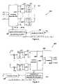
- FIG. 7is a block diagram illustrating an equivalent structure of the precoding and combining at a sub carrier k of the MIMO-OFDM communication system of FIG. 6 .
- FIG. 8is a block diagram illustrating a transmitter of the MIMO-OFDM communication system of FIG. 6 .
- FIG. 9is a block diagram illustrating a receiver of the MIMO-OFDM s communication system of FIG. 6 .
- FIG. 10is a block diagram illustrating a precoding scheme of the MIMO-OFDM communication system of FIG. 6 .
- MIMO systemsprovide improved reliability over fading channels, because the increased dimension of a MIMO system may be used to mitigate signal-level fluctuations. Transmit beamforming with receive combining is a method to exploit the diversity offered by MIMO systems.
- the beamforming techniques for narrowband channelsmay be extended to frequency selective MIMO channels by employing orthogonal frequency division multiplexing (OFDM).
- OFDMorthogonal frequency division multiplexing
- the use of MIMO technology in combination with OFDM, e.g., “MIMO-OFDM,”converts a broadband MIMO channel into multiple narrowband MIMO channels corresponding to OFDM subcarriers.
- the transmitter of the MIMO-OFDM Systemuses the beamforming vector for each subcarrier.
- the feedbackincreases in proportion to the number of subcarriers.
- a transmit beamforming system and methodcombines limited feedback of beamforming information and interpolation of beamforming vectors.
- a receivermay select a fraction of subcarriers and send back the beamforming vectors for the selected subcarriers to the transmitter.
- the transmittermay evaluate the beamforming vectors for all the OFDM subcarriers through interpolation of the conveyed beamforming vectors.
- the transmittermay include a spherical interpolator.
- the spherical interpolatormay employ a parameter for phase rotation which is determined to minimize the distortion induced by interpolation.
- FIG. 1illustrates a MIMO-OFDM communication system 100 with transmit beamforming and receive combining.
- the MIMO-OFDM system 100comprises a transmitter 102 , a receiver 103 , a communication channel 104 , and a feedback network 105 .
- the transmitter 302 ( FIG. 3 ) and the receiver 400 ( FIG. 4 )may be used instead of the transmitter 102 and the receiver 103 , respectively.
- the transmitter 102comprises a transmit beamforming system 110 , a plurality of inverse discrete Fourier transform (IDFT) units 111 , a plurality of parallel to serial (P/S) & ADD Cyclic prefix (CP) units 112 , and a plurality of transmit antennas 113 .
- IDFTinverse discrete Fourier transform
- P/Sparallel to serial
- CPCyclic prefix
- the receiver 103comprises a receive combining unit 120 , a plurality of discrete Fourier transform (DFT) units 121 , a plurality of remove CP & serial to parallel (S/P) units 122 , and a plurality of received antennas 123 .
- DFTdiscrete Fourier transform
- S/Premove CP & serial to parallel
- the MIMO-OFDM system 100comprises M r receive antennas 123 , and N subcarriers.
- the numbers M t and M rmay be randomly chosen and N is usually set as a power of two.
- the communication channel 104may be frequency selective.
- the system 100may be modified for use in a multiple-input single-output (MISO) system.
- the MISO systemmay have a plurality of transmit antennas 113 and a single receive antenna 123 .
- the communication channel 104becomes a MISO channel.
- the symbols ⁇ s(1), s(2), . . . , s(N) ⁇are simultaneously transmitted through M t antennas 113 .
- the signal received through each receiver antenna 123is demodulated by the discrete Fourier transform (DFT) processors 121 and combined to recover the transmitted symbols.
- the information about the beamforming vectorsis conveyed to the transmitter 102 through the feedback channel 105 with limited rate.
- FIG. 2shows an equivalent structure for beamforming and combining at subcarrier k.
- w(k) and z(k)denote the transmit beamforming vector and receive combining vector at subcarrier k, respectively.
- the symbol s(k)is mapped to the transmit antennas 113 by the beamforming vector w(k), and the signals obtained from the receive antennas 123 are combined by z(k).
- the transmit beamforming vector w(k)is an equivalent vector for the transmit beamforming unit 110 , the IDFT units 111 , and the CP units 112 .
- the receive combining vector z(k)is an equivalent structure for the S/P units 122 , the DFT units 121 , and the receive combining unit 120 .
- FIG. 3shows one embodiment of the MIMO-OFDM beamforming in a transmitter 302 according to the present invention.
- the transmitter 302is similar to the transmitter 102 ( FIG. 1 ) but includes a spherical interpolation of the beamforming vectors from the feedback channel 105 .
- the transmitter 302calculates the beamforming vectors for all the subcarriers using a fraction of beamforming vectors and the parameters for interpolation, which are available from the feedback channel 105 which the spherical interpolator 305 performs.
- the remaining blocksare the same as those for the MIMO-OFDM system 100 ( FIG. 1 ).
- the ⁇ w(1). . . w(N) ⁇is the interpolated beamforming.
- the interpolationmay use, for example, uniformly spaced carriers, nonuniform spaced carriers or quantized channel information.
- the operation of the transmitter 302is described in more detail below.
- FIG. 4illustrates one embodiment of a receiver 400 according to the present invention.
- the receiver 400may be used instead of the receiver 103 in the system 100 .
- the receiver 400is similar to the receiver 103 but includes a receiving combining unit 420 , and a beamforming vector and interpolation parameter unit 422 .
- the receive combining unit 420comprises a channel estimator 430 , a maximum rate combining (MRC) unit 431 , and a detector 432 .
- MRCmaximum rate combining
- the MRC unit 431executes an MRC for each subcarrier separately and the transmitted symbols are recovered from the combined signals.
- the detector 432may be, for example, a linear detector, a non-linear detector, a linear equalizer, a maximum likelihood sequencing detector, MMSE, a sphere decoder or other detectors well known in the art.
- the receiver 400subsamples the subcarriers, e.g., selects a fraction of subcarriers.
- Kis the subsampling rate which is usually set as a divisor of N.
- the receiver 400evaluates the beamforming vectors for the selected subcarriers, ⁇ w(1), w(K+1), . . . , w(N ⁇ K+1) ⁇ .
- the receiver 400finds the parameters for phase rotation
- the beamforming vectorsare sent back to the transmitter 302 along with the parameters for phase rotation through the feedback channel 105 .
- the receiver 400samples the subcarriers nonuniformly. The operation of the receiver 400 is described in more detail below.
- FIG. 5illustrates one embodiment of the spherical interpolator 305 .
- the beamforming vectorsare computed by blockwise interpolation in a plurality of interpolators 501 - 1 through 501-N.
- Each interpolator 501includes a weighted sum unit 510 and a normalization unit 511 .
- ⁇ w(1), w(2), . . . , w(K) ⁇are obtained from w(1), w(K+1), and ⁇ 0 .
- w((l+1)K) ⁇are obtained from w(lK+1), w((l+1)K+1), and ⁇ 1 .
- ⁇ N K - 1are used to evaluate ⁇ w(N ⁇ K+1), w(N ⁇ K+2), . . . , w(N) ⁇ in the last interpolator 501-N.
- the interpolated beamforming vectors ⁇ w(1), w(2), . . . , w(N) ⁇are used for the transmit beamforming in the transmitter 302 ( FIG. 3 .) MIMO-OFDM Systems with Limited Feedback
- MIMO systemswhich use multiple antennas at both transmitter and receiver, provide increased spectral efficiency or improved reliability over fading channels.
- a MIMO communication systemoffers a significant improvement in data rate through spatial multiplexing.
- the increased dimension of a MIMO systemis used to mitigate signal-level fluctuations in fading channels.
- transmit beamforming with receive combiningis a simple approach to achieving the full diversity order as well as additional array gain.
- non-reciprocal channelsas in a frequency division duplexing system
- thisnecessitates that the receiver sends back the channel state information in the form of the beamforming vector through a feedback channel with limited rate.
- a practical solution for reducing the feedback informationis to use a codebook of possible beamforming vectors which is known to both the transmitter and receiver (see e.g., the references Narula, Love and R. W. Heath, Jr., and Mukkavilli references cited below in conjunction with the codebook.).
- the beamforming techniques proposed for narrowband channelsmay be extended to frequency selective MIMO channels by employing OFDM.
- a broadband MIMO channelis divided into a set of parallel narrowband MIMO channels, e.g., it converts a broadband MIMO channel into multiple narrowband MIMO channels.
- transmit beamforming and receive combiningmay be performed independently for each subcarrier.
- the MIMO-OFDM receiversends back the beamforming vectors for all the OFDM subcarriers to the transmitter.
- FIG. 1A MIMO-OFDM system with transmit beamforming and receive combining, using M t transmit antennas and M r receive antennas, and N subcarriers is illustrated in FIG. 1 .
- the subchannels of OFDMare separated to N narrowband channels. As shown in FIG.
- the subchannel for the k-th subcarriermay be described by a M r -by-M t matrix H(k) whose entries represent the channel gains experienced by subcarrier k.
- the vector zmay be such that ⁇ z(k) ⁇ 1.
- SNRsignal to noise ratio
- w(k) and z(k)are designed to maximize the SNR for each subcarrier.
- the receiver 400uses MRC given by
- MRTmaximum ratio transmission
- a transmit beamforming methodthat combines limited feedback of beamforming information and interpolation of beamforming vectors. Since the length of cyclic prefix is designed to be much less than the number of subcarriers, the neighboring subchannels of OFDM is substantially correlated. In MIMO-OFDM, the beamforming vectors are determined by the corresponding subchannels and hence the beamforming vectors for the neighboring subchannels are also significantly correlated. To reduce the feedback information using the correlation, the receiver 400 selects a fraction of subcarriers and sends back the beamforming vectors only for the selected subcarriers. Then the transmitter 302 evaluates the beamforming vectors for all the subcarriers through interpolation of the conveyed beamforming vectors.
- This beamforming schemeuses much less feedback information than ideal beamforming with feedback for all subcarriers, while it performs close to the ideal beamforming. This advantage is accomplished by the following processes that are used to implement the system 100 :
- the transmitter 302 for the MIMO-OFDM beamforming system 100comprises a beamformer interpolator 305 , a transmit beamforming unit 110 , and OFDM modulators as part of the IDFT units 111 .
- the beamformer interpolator 305calculates the beamforming vectors for all the subcarriers using a fraction of beamforming vectors and the parameters for interpolation, which are conveyed through the feedback channel 105 .
- the symbolsare mapped to transmit antennas 113 using the interpolated beamforming vectors.
- the mapped signalsare OFDM modulated.
- a spherical interpolatormay be used for interpolation of beamforming vectors.
- some spherical interpolatorsperform weighted averages of beamforming vectors and renormalize the result to place on the unit sphere. See, e.g. S. R. Buss and J. P. Fillmore, “Spherical averages and applications to spherical splines and interpolation,” ACM Trans. Graphics, vol. 20, no. 2, pp. 95-126, Apr. 2001; K. Shoemake, “Animating rotation with quaternion curves,” in Proc.
- the spherical interpolator 305interpolates beamforming vectors. Given ⁇ w(1), w(K+1), . . . , w(N ⁇ K+1) ⁇ , the interpolator 305 interpolates using a vector
- FIG. 5which illustrates the interpolator 305 as a block diagram. While conventional spherical interpolators only utilize w(lK+1) and w((l+1)K+1), the interpolator 305 evaluates the beamforming vector from w(lK+1) and e j ⁇ l w((l+1)K+1). The role of ⁇ l is to remove the distortion caused by the arbitrary phase rotation of the optimal beamforming vectors. The criteria for determining ⁇ l are explained below. Determination of Parameters for Interpolation
- the receiver 400evaluates the optimal phase
- the beamforming vectors for the other subcarriersare computed by equation (4).
- the channel matrices ⁇ H(k),1 ⁇ k ⁇ N ⁇are known to the receiver 400 .
- ⁇ H(k),1 ⁇ k ⁇ N ⁇may be estimated by training or pilot symbols as shown in FIG. 4 .
- the receiver 400Given the subsampling rate K, the receiver 400 calculates ⁇ w(1), w(K+1), . . . , w(N ⁇ K+1) ⁇ using the channel matrices.
- a cost functionis defined to find the optimal parameters ⁇ l ⁇ in the sense of maximizing the minimum effective channel gain or capacity. First, the optimal solution maximizing the cost function is obtained by a numerical grid search, and then a closed-form solution is obtained through some modifications of the cost function.
- ⁇ 1arg ⁇ ⁇ max ⁇ ⁇ ⁇ min ⁇ ⁇ ⁇ H ⁇ ( l ⁇ ⁇ K + k ) ⁇ w ⁇ ⁇ ( l ⁇ ⁇ K + k ; ⁇ ) ⁇ 2 , 1 ⁇ k ⁇ K ⁇ ( 5 )
- equation (5)Due to the normalization factor in equation (5), it is not easy to get a closed-form solution. Instead, a numerical grid search may be used by modifying equation (5) as
- ⁇ 1a ⁇ ⁇ r ⁇ g ⁇ ⁇ max ⁇ ⁇ ⁇ ⁇ ⁇ min ⁇ ⁇ ⁇ H ⁇ ( l ⁇ ⁇ K + k ) ⁇ w ⁇ ⁇ ( l ⁇ ⁇ K + k ; ⁇ ) ⁇ 2 , 1 ⁇ k ⁇ K ⁇ ( 6 )
- ⁇⁇ 0 , 2 ⁇ ⁇ P , 4 ⁇ ⁇ P , ⁇ ⁇ ⁇ , 2 ⁇ ( P - 1 ) ⁇ ⁇ P ⁇ and P is the number of quantized levels which determines the performance and complexity of the search.
- equation (5)may be simplified by considering the average effective channel gain.
- the subcarrierIn general, the subcarrier
- Equation (5)( l ⁇ ⁇ k + K 2 + 1 ) has the minimum effective channel gain among the subcarriers (lK+1) and ((l+1)K+1). Using this fact, equation (5) may be approximated to maximize the effective channel gain of the subcarrier
- RH H ⁇ ( l ⁇ ⁇ K + K 2 + 1 ) ⁇ H ⁇ ( l ⁇ ⁇ K + K 2 + 1 ) .
- ⁇ 2⁇ - ⁇ 1 + ⁇ - ⁇ if ⁇ ⁇ ⁇ ⁇ 0 - ⁇ 1 - ⁇ - ⁇ if ⁇ ⁇ ⁇ ⁇ 0 ( 11 )
- ⁇ 1may be determined to maximize the sum rate of all the OFDM subcarriers, assuming that the transmit power is identically assigned to all subcarriers.
- the optimal phase maximizing the sum rateis determined by
- ⁇ l( l ⁇ ⁇ k + K 2 + 1 ) has the worst average effective channel gain, ⁇ l may be approximately found by
- ⁇ larg ⁇ ⁇ ⁇ max ⁇ ⁇ ⁇ log 2 ⁇ ⁇ 1 + ⁇ H ⁇ ( l ⁇ ⁇ K + K 2 + 1 ) ⁇ w ⁇ ⁇ ( l ⁇ ⁇ K + K 2 + 1 ; ⁇ ) ⁇ 2 N 0 ⁇ ( 14 )
- the beamforming method for MIMO-OFDM system 100uses the feedback of selected beamforming vectors and phase rotation parameters. To accommodate the limited bandwidth of the feedback channel, the selected beamforming vectors ⁇ w(1), w(K+1), . . . , w(N ⁇ K+1) ⁇ and the parameters ⁇ l ⁇ are quantized. To quantize the beamforming vectors, the transmitter 302 and receiver 400 may use a codebook designed for narrowband MIMO systems, such as disclosed in A. Narula, M. J. Lopez, M. D. Trott, and G. W. Wornell, “Efficient use of side information in multiple-antenna data transmission over fading channels,” IEEE J. Select. Areas Commun., vol. 16, no. 8, pp.
- the quantized beamforming vectorsare in turn used to find the optimal ⁇ l and ⁇ l is uniformly quantized on [0, 2 ⁇ ).
- the receiver 400quantizes the beamforming vectors by selecting the beamforming vector which maximizes the effective channel gain from the codebook as follows.
- w Q ⁇ ( lK + 1 )arg ⁇ ⁇ max x ⁇ W ⁇ ⁇ ⁇ H ⁇ ( l ⁇ ⁇ K + 1 ) ⁇ x ⁇ ( 15 )
- Wis the codebook including all possible beamforming vectors
- the receiver 400determines the optimal phase and the transmitter 302 interpolates the beamforming vectors for all subcarriers.
- ⁇ l ⁇are found in the sense of maximizing the minimum effective channel gain or capacity. Phase Optimization in the Sense of Maximizing the Minimum Effective Channel Gain
- ⁇ larg ⁇ ⁇ ⁇ max ⁇ ⁇ ⁇ ⁇ ⁇ min ⁇ ⁇ ⁇ H ⁇ ( l ⁇ ⁇ K + k ) ⁇ w Q ⁇ ( l ⁇ ⁇ K + k ; ⁇ ) ⁇ 2 , 1 ⁇ k ⁇ K ⁇ ( 16 ) where the interpolated vector w Q (lK+k; ⁇ l ) is given by
- the interpolator 305 with quantized beamforming vectorsmay be optimized to maximize the sum rate of all the subcarriers.
- the optimal ⁇ lis determined by replacing ⁇ (lK+k; ⁇ ) with ⁇ Q (lK+k; ⁇ ) as follows.
- the MIMO-OFDM system 100 combined with transmit beamforming and receive combiningmay achieve the full diversity order as well as maximum array gain available.
- this approachuses the knowledge about beamforming vectors corresponding to all the subcarriers at the transmitter 302 .
- the receiver 400sends back the channel state information in the form of beamforming vectors.
- each beamforming vectormay be quantized by using a codebook designed for narrowband MIMO channels. The feedback increases in proportion to the number of subcarriers.
- a transmit beamforming methodcombines limited feedback and beamformer interpolation.
- the receiver 400sends back just a fraction of information about the beamforming vectors along with the parameters for phase rotation, and the transmitter recovers the beamforming vectors for all subcarriers.
- the receiver 400selects only a fraction of beamforming vectors and finds the optimal parameters for phase rotation to maximize the minimum channel gain or capacity, and conveys the information to the transmitter 302 .
- the transmitter 302recovers the beamforming vectors for all the subcarriers using the spherical interpolator 305 .
- the beamforming methoduses much less feedback information than the ideal beamforming with feedback of all subcarriers, while it performs close to the ideal beamforming.
- a simple beamforming method to reduce the amount of information for the beamforming vectorsis to combine the neighboring subcarriers into a cluster and use the beamforming vector corresponding to the center subcarrier in the cluster. This method will be referred to as clustering.
- the channel state informationis sent back to the transmitter.
- a practical solutionis to use the transmit beamforming with receive combining and convey the information about the quantized beamforming vectors using a codebook which is known to both the transmitter and receiver.
- the feedback requirementsstill increase in proportion to the number of subcarriers.
- precodingallows the system to send multiple data streams in parallel using spatial multiplexing. This allows the high spectral efficiency of MIMI systems to be used.
- spatial multiplexinga bit stream is demultiplexed into multiple substreams, which are independently modulated and transmitted over different antennas.
- Linear precodingis a method of premultiplying the transmitted data streams by a matrix, chosen based on channel information, with the objective of improving the robustness of spatial multiplexing to the rank deficiencies of the channel.
- Precodingmay be used with full channel state information or first/second order channel statistics.
- the precodingmay be done with a limited feedback system that provides quantized channel information to the transmitter through a feedback channel, or by directly quantizing a set of precoding matrices.
- the systemreduces the total amount of feedback by exploiting the correlation of precoding matrices on adjacent subcarriers by sending back the precoding matrices for only a fraction of the subcarriers as well as some auxiliary information.
- the precodersare quantized by selecting the best precoder from a codebook of precoding matrices, which depends on the performance criterion such as minimizing the mean squared error (MMSE) or maximizing the capacity.
- MMSEmean squared error
- the transmitterreconstructs the precoding matrices for all OFDM subcarriers through a special interpolation function. To meet the orthonormality constraints, a weighted sum of the two nearest conveyed precoders may be determined and then an orthonormal projection is performed.
- a unitary derotation matrix Qis associated with precoder interpolation.
- Qis determined to optimize the performance of the interpolator using the same performance measure as for quantization, e.g., MMSE or capacity maximization. Because closed form optimization of Q is difficult, the Q may be selected from a finite codebook of unitary matrices, because it may be quantized to reduce feedback.
- the information about Qis sent back to the transmitter along with the information about the precoders for the selected subcarriers.
- FIG. 6is a block diagram illustrating a multiple-input multiple-output—orthogonal frequency division multiplex (MIMO-OFDM) communication system 600 with precoding.
- MIMO-OFDMmultiple-input multiple-output—orthogonal frequency division multiplex
- the MIMO-OFDM system 600uses precoding.
- the beamforming of FIG. 1may be one embodiment of precoding.
- the MIMO-OFDM system 600comprises a transmitter 602 , a receiver 603 , a communication channel 604 , and a feedback network 605 .
- the transmitter 802 ( FIG. 8 ) and the receiver 900 ( FIG. 9 )may be used instead of the transmitter 602 and the receiver 603 , respectively.
- the transmitter 602comprises a precoding unit 610 , a plurality of inverse discrete Fourier transform (IDFT) units 611 , a plurality of parallel to serial (P/S) & ADD Cyclic prefix (CP) units 612 , and a plurality of transmit antennas 613 .
- IDFTinverse discrete Fourier transform
- P/Sparallel to serial
- CPCyclic prefix
- the receiver 603comprises a receive processing unit 620 , a plurality of discrete Fourier transform (DFT) units 621 , a plurality of remove CP & serial to parallel (S/P) units 622 , and a plurality of received antennas 623 .
- DFTdiscrete Fourier transform
- S/Premove CP & serial to parallel
- the MIMO-OFDM system 600comprises M r receive antennas 623 , and N subcarriers.
- the numbers M t and M rmay be randomly chosen and N is usually set as a power of two.
- the communication channel 604may be frequency selective.
- the system 600may be modified for use in a multiple-input single-output (MISO) system.
- the MISO systemmay have a plurality of transmit antennas 613 and a single receive antenna 623 .
- the communication channel 604becomes a MISO channel.
- the vectors s(1), s(2), . . . s(N)are simultaneously transmitted through M t antennas 613 .
- the signal received through each receiver antenna 623is demodulated by the discrete Fourier transform (DFT) processors 621 and combined to recover the transmitted vectors.
- the information about the vectorsis conveyed to the transmitter 602 through the feedback channel 605 with limited rate.
- the transmitter 602may transmit multiple data streams simultaneously.
- the precoding of the transmitter 602may be linear precoding, which premultiplies transmitted data streams by a matrix, which may be chosen based on channel information.
- the precodingmay be based on full channel state information or first/second order channel statistics.
- the precodingmay be based on limited feedback from the receiver 603 .
- the precodingmay include precoder quantization and further include interpolation.
- the precodingmay use a fraction of the subcarriers, for example, based on correlation of precoding matrices on adjacent subcarriers.
- the precodingmay use a codebook.
- FIG. 7is a block diagram illustrating an equivalent structure of the precoding and combining at a sub carrier k of the MIMO-OFDM system 600 .
- the matrix W(k)is a matrix of the precoding of the transmitter at subcarrier k, or in other words, the output of the reconstruct unit 805 ( FIG. 8 ).
- the communication channel 604has a matrix H characteristics.
- the transmit precoding matrix W(k)is determined based on matrix H.
- the input vector sis mapped to the transmit antennas 613 by the precoding matrix W(k), and the vector output from the receiver are determined by the receive processing and detection.
- the precoding matrix W(k)is a precoding matrix for the transmit precoding unit 610 , the IDFT units 611 , and the CP units 612 .
- FIG. 8is a block diagram illustrating a transmitter 802 of the MIMO-OFDM system of FIG. 6 .
- the transmitter 802is similar to the transmitter 602 ( FIG. 6 ) but includes a reconstruct transmit precoding matrices unit 805 .
- the transmitter 802calculates the precoding matrix for all the subcarriers using a fraction of vectors and the parameters for interpolation, which are available from the feedback channel 605 which the unit 805 performs.
- the remaining blocksare the same as those for the MIMO-OFDM system 600 ( FIG. 6 ).
- the operation of the transmitter 802is described in more detail below.
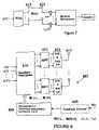
- FIG. 9is a block diagram illustrating a receiver 900 of the MIMO-OFDM system 600 of FIG. 6 .
- the receiver 900may be used instead of the receiver 603 in the system 600 .
- the receiver 900is similar to the receiver 603 but includes a receiving combining unit 920 , and a feedback computation unit 922 .
- the receive combining unit 920comprises a channel estimator 930 , a receive processing unit 931 , and a detector 932 .
- the receive processing unit 631recovers the transmitted vectors for each subcarrier separately from the combined signals.
- the feedback vectors used at the transmitter 802are computed.
- the detector 932may be, for example, a linear detector, a non-linear detector, a linear equalizer, a maximum likelihood sequencing detector, MMSE, a sphere decoder or other detectors well known in the art.
- the receiver 900subsamples the subcarriers, e.g., selects a fraction of subcarriers, and selects the corresponding vectors. In addition, the receiver 900 finds the parameters for the precoding interpolation. The vectors are sent back to the transmitter 902 along with the parameters through the feedback channel 605 . In another embodiment, the receiver 900 samples the subcarriers nonuniformly.
- FIG. 10is a block diagram illustrating the reconstruct transmit precoding matrices unit 805 .
- the unit 805may be similar to the interpolator 305 , but operates on vectors to form the interpolation for the precoding matrix W.
- the precoding matrix Wis computed by blockwise interpolation in a plurality of interpolators 1001 .
- Each interpolator 1001includes a weighted sum unit 1010 and a normalization unit 1011 .
- the matrices W(2) to W(K)are obtained from W(1) and W(K+1), and Q 0 .
- W(lK+2) to W((l+1)K)are obtained from, W(lK+1) to W((l+1)K+1) and Qi.
- the interpolated precoding matrix Ware used for the transmit precoding in the transmitter 802 ( FIG. 8 .)
- W(k)is an element of a set of a finite codebook.
- the code wordsmay be chosen based on a desired performance metric, such as mean squared error (MSE) or mutual information.
- MSEmean squared error
- the precodingis quantized precoding with a finite search.
- the precodingis Grassmannian precoding. This may provide optimal packing of the codebook. Further, the distance measures may depend on precoding criteria, such as projection 2-norm for MMSE with trace, or Fubini-Study distance for capacity and MMSE with determinant. The Grassmannian precoding may minimize the bound on average distortion in Rayleigh channels.
- the precodingmay use clustering to reduce feedback.
- Such precodinguses the coherence bandwidth of the channel. For example, every Kth precoding matrix may be uses, and the same precoding matrix per cluster may be used. This may cause some performance degradation at the cluster boundary.
- the transmitteruses subsampling and interpolation for the precoding matrices.
- a uniform set of unitary matricesmay be used.
- One method for interpolationincludes a first quantization step and a second optimization step.
- the feedback bitsuse precoding matrices [ N/K ] log 2
- the system 100 or 600may be a time-divisional duplex system.
- the feedbackmay be determined from channel reciprocity.
- channel reciprocityuses the receive channel to infer the transmit channel.
- the code bookmay be generated, for example, from quantized parameters for Givens rotations or mutually unbiased bases (MUB).
- the code book of unitary matrices ⁇may be generated based on the probability distribution of equation (24) or an estimate of the distribution, such as isotropically random. In the example of an isotropically random distribution, the unitary matrices ⁇ may be selected so that they are uniformly distributed in the space of unitary matrices.
- the matrices ⁇may be formed by forming a set of orthogonal bases (ONB) such that the maximal correlation between elements of different ONBs is minimum and equal to 1/M s .
- ONBorthogonal bases
- Each ONMrepresents a unitary matrix, an element of ⁇ .
- the matrices ⁇may be designed for an arbitrary M s and cardinality.
- the unitary matricesmay be parameterized and then the parameter space is quantized.
- the parameterizationsmay be obtained by decomposing a unitary matrix into Givens rotations.
- a unitary matrix Q ⁇ C M, ⁇ M,can be decomposed as
- the parameterizationbecomes a unitary matrix Q ⁇ C M, ⁇ M, into M s 2 parameters ⁇ k,j , ⁇ k,l . ⁇ . Further, in case the unitary matrix is isotropically random, the distributions of the parameters are given by the following.
- a general methodis to use standard processes for vector quantizer design, for example, a Lloyd algorithm to jointly determine the reconstruction points for all the parameters ⁇ circumflex over ( ⁇ ) ⁇ k,j , ⁇ circumflex over ( ⁇ ) ⁇ k,l ⁇ .
- the codebook of unitary matrices, ⁇is designed by reconstructing unitary matrices from the quantized parameters ⁇ circumflex over ( ⁇ ) ⁇ k,j , ⁇ circumflex over ( ⁇ ) ⁇ k,l ⁇ .
- the MIMO-OFDM systems 100 and 600may be used, for example, for wireless indoor communication systems, such as IEEE 802.16 standard systems, IEEE 802.11n standard wireless LANs, and IEEE 802.20 standard Mobile Broadband Wireless Access (MBWA) systems, or used for other systems, such as 4G wireless cellular systems.
- wireless indoor communication systemssuch as IEEE 802.16 standard systems, IEEE 802.11n standard wireless LANs, and IEEE 802.20 standard Mobile Broadband Wireless Access (MBWA) systems
- MBWAMobile Broadband Wireless Access
Landscapes
- Engineering & Computer Science (AREA)
- Signal Processing (AREA)
- Computer Networks & Wireless Communication (AREA)
- Physics & Mathematics (AREA)
- Mathematical Physics (AREA)
- Radio Transmission System (AREA)
Abstract
Description
minimizing the distortion induced by interpolation. The beamforming vectors are sent back to the
are used to evaluate {w(N−K+1), w(N−K+2), . . . , w(N)} in the last interpolator 501-N. The interpolated beamforming vectors {w(1), w(2), . . . , w(N)} are used for the transmit beamforming in the transmitter302 (
MIMO-OFDM Systems with Limited Feedback
r(k)=zH(k){H(k)w(k)s(k)+n(k)}, 1≦k≦N (1)
where n(k) is the Mr-dimensional noise vector with zero mean and variance N0. In one embodiment, it may be assumed that the power is allocated equally across all subcarriers, thus E[|s(k)|2] is a constant and ∥w(k)∥=1 (where means 2-norm of (·) to maintain the overall power constraints. Without loss of generality, the vector z may be such that ∥z(k)∥−1. Then the signal to noise ratio (SNR) for subcarrier k may be written as
where Γ(k)=|zH(k)H(k)w(k)|2is the effective channel gain.
- i)
spherical interpolator 305 used at thetransmitter 302 - ii) Determination of parameters for interpolation at the
receiver 400 - iii) Interpolation of beamforming vectors with quantization
One Embodiment of theSpherical Interpolator 305
- i)
where ck=(k−1)/K is the linear weight value, w(N+1)=w(1), 1≦k≦K, θ1is a parameter for phase rotation with
Refer again to
Determination of Parameters for Interpolation
based on a performance metric, and conveys {θl} along with the selected beamforming vectors to the
where
Due to the normalization factor in equation (5), it is not easy to get a closed-form solution. Instead, a numerical grid search may be used by modifying equation (5) as
where
and P is the number of quantized levels which determines the performance and complexity of the search.
has the minimum effective channel gain among the subcarriers (lK+1) and ((l+1)K+1). Using this fact, equation (5) may be approximated to maximize the effective channel gain of the subcarrier
and then θlis obtained by
where w1=w(lK+1), w2=w((l+1)K+1), and
To find the optimal solution, the cost function is differentiated with respect to θland then the optimal solution satisfies
j{α1ejθ+(α2−α2*)−α1*e−jθ}=0 (8)
where α1=(w1HRw2)(w1Hw1+w2Hw2)−(w1HRw1)(w1Hw2)−(w2HRw2)(w1Hw2) and α2=2(w1HRw2)(w2Hw1). Combining αlejθand α1*e−jθresults in
Im(α1ejθ+α2)=0 (9)
where Im(•) means the imaginary part of (•). It may be proved that there always exists θ that satisfies equation (9). Denote αi=|αi|ejθ
θ1=−Φ1+ε (10)
where
Also, the derivative of equation (8) becomes −2 Re(α1ejθ) where Re(•) means the real part of (•). Thus, the optimal θlmaximizing the cost function is one of the solutions θ1and θ2such that −2Re(α1ejθ) is negative. This solution will be referred to as the closed-form solution.
Phase Optimization in the Sense of Maximizing Capacity
and the optimal solution is obtained by using the numerical grid search as follows.
Using the fact that the subcarrier
has the worst average effective channel gain, θlmay be approximately found by
where W is the codebook including all possible beamforming vectors and
Using the quantized beamforming vectors, the
Phase Optimization in the Sense of Maximizing the Minimum Effective Channel Gain
where the interpolated vector wQ(lK+k; θl) is given by
Phase Optimization for Maximizing Capacity
where |W| is the cardinality of the chosen beamforming codebook.
Overall System Summary
Y(k)=H(k)W(k)s(k)+v(k), (19)
where H(k), W(k), and s(k) are described above in conjunction with
Z(l K+k)=(1−Ck)W(lK+k)+ckW((l+1)K+1) (20)
and
Ŵ(l K+k)=Z(l K+k){ZH(lK+k)Z(lK+k)}−1/2 (21)
with ck=(k−1)/K. The Ŵ(lK+k) is the interpolated precoding.
Z(l K+k)=(1−ck)W(lK+k)+ckW((l+1)K+1)Q1 (22)
Where Q1is a M×M unitary matrix.
θ={Q1, Q2, . . . Q2P} (23)
to enable limited feedback. A uniform set of unitary matrices may be used.
Q1=arg min max tr (MSE(Ŵ(lK+k; Q') withQ'εθandk=0 . . .K−1. (24)
precoding matrices [N/K] log2|W| (25)
and
derotation matrices[N/K] log2|θ| (26)
where the Msdimensional diagonal matrix
Dk(φk,k, . . . , φk,M
1k−1is (k−1) 1's, Gp-1p(θ) is the Givens matrix which operates in the (p−1, p) coordinate plane of the form
p(θk,l)=2lsin2l−1θk,lcos θk,l, 0≦θk,l<π/2. (30)
Further a method to quantize the unitary matrices is to do independent scaler quantization of the parameters {Øk,j, θkj.} with squared error distortion metric. An adhoc approach is to allocate R bits to the different parameters equally. The parameters {Øk,j} are quantized uniformly and the reconstruction points {{circumflex over (φ)}k,j} have closed form expressions. In some cases, quantization of {θk,l,} leads to closed form expressions for the re-construction points (for example Ms=2 and 1-bit quantization of θ1,1). A general method is to use standard processes for vector quantizer design, for example, a Lloyd algorithm to jointly determine the reconstruction points for all the parameters {{circumflex over (φ)}k,j,{circumflex over (θ)}k,l}. The codebook of unitary matrices, θ is designed by reconstructing unitary matrices from the quantized parameters {{circumflex over (φ)}k,j, {circumflex over (θ)}k,l}.
Claims (43)
W(k)HW(k)=1/MIM;
Z(lK+k)=(1−ck)W(lK+k)+ckW((1+1)K+1)
Ŵ(IK+k)=Z(IK+k){ZH(IK+k)Z(IK+k)}−1/2
Priority Applications (1)
| Application Number | Priority Date | Filing Date | Title |
|---|---|---|---|
| US11/188,233US7676007B1 (en) | 2004-07-21 | 2005-07-21 | System and method for interpolation based transmit beamforming for MIMO-OFDM with partial feedback |
Applications Claiming Priority (2)
| Application Number | Priority Date | Filing Date | Title |
|---|---|---|---|
| US58971304P | 2004-07-21 | 2004-07-21 | |
| US11/188,233US7676007B1 (en) | 2004-07-21 | 2005-07-21 | System and method for interpolation based transmit beamforming for MIMO-OFDM with partial feedback |
Publications (1)
| Publication Number | Publication Date |
|---|---|
| US7676007B1true US7676007B1 (en) | 2010-03-09 |
Family
ID=41785056
Family Applications (1)
| Application Number | Title | Priority Date | Filing Date |
|---|---|---|---|
| US11/188,233Active2028-08-29US7676007B1 (en) | 2004-07-21 | 2005-07-21 | System and method for interpolation based transmit beamforming for MIMO-OFDM with partial feedback |
Country Status (1)
| Country | Link |
|---|---|
| US (1) | US7676007B1 (en) |
Cited By (114)
| Publication number | Priority date | Publication date | Assignee | Title |
|---|---|---|---|---|
| US20060203891A1 (en)* | 2005-03-10 | 2006-09-14 | Hemanth Sampath | Systems and methods for beamforming and rate control in a multi-input multi-output communication systems |
| US20060209670A1 (en)* | 2005-03-17 | 2006-09-21 | Alexei Gorokhov | Pilot signal transmission for an orthogonal frequency division wireless communication system |
| US20060209732A1 (en)* | 2005-03-17 | 2006-09-21 | Qualcomm Incorporated | Pilot signal transmission for an orthogonal frequency division wireless communication system |
| US20060233131A1 (en)* | 2005-04-19 | 2006-10-19 | Qualcomm Incorporated | Channel quality reporting for adaptive sectorization |
| US20070041404A1 (en)* | 2005-08-08 | 2007-02-22 | Ravi Palanki | Code division multiplexing in a single-carrier frequency division multiple access system |
| US20070041457A1 (en)* | 2005-08-22 | 2007-02-22 | Tamer Kadous | Method and apparatus for providing antenna diversity in a wireless communication system |
| US20070049218A1 (en)* | 2005-08-30 | 2007-03-01 | Qualcomm Incorporated | Precoding and SDMA support |
| US20070097897A1 (en)* | 2005-10-27 | 2007-05-03 | Qualcomm Incorporated | Method and apparatus for bootstraping information in a communication system |
| US20070097927A1 (en)* | 2005-10-27 | 2007-05-03 | Alexei Gorokhov | Puncturing signaling channel for a wireless communication system |
| US20070097856A1 (en)* | 2005-10-28 | 2007-05-03 | Jibing Wang | Unitary precoding based on randomized fft matrices |
| US20070097853A1 (en)* | 2005-10-27 | 2007-05-03 | Qualcomm Incorporated | Shared signaling channel |
| US20070115909A1 (en)* | 2005-10-27 | 2007-05-24 | Jibing Wang | Linear precoding for time division duplex system |
| US20070270112A1 (en)* | 2006-05-22 | 2007-11-22 | Samsung Electronics Co., Ltd. | Apparatus and method for cooperative maximum ratio transmission in a broadband wireless access communication system |
| US20080095258A1 (en)* | 2006-10-19 | 2008-04-24 | Xiaoming She | Pre-coding method for mimo system and apparatus using the method |
| US20080101494A1 (en)* | 2006-10-31 | 2008-05-01 | Freescale Semiconductor, Inc. | System and method for generating MIMO signals |
| US20080137781A1 (en)* | 2006-12-07 | 2008-06-12 | Electronics And Telecommunications Research Institute | METHOD OF DETECTING SPACE-TIME CODE IN MOBILE COMMUNICATION SYSTEM WITH 4 Tx ANTENNA |
| US20080165836A1 (en)* | 2007-01-09 | 2008-07-10 | Uri Landau | Method and system for controlling and regulating services and resources in high-performance downlink channels |
| US20080165877A1 (en)* | 2007-01-08 | 2008-07-10 | Navini Networks, Inc. | Method and system for transmitting data streams via a beamformed MIMO channel |
| US20080165868A1 (en)* | 2007-01-09 | 2008-07-10 | Mark Kent | Method and system for codebook design of mimo pre-coders with finite rate channel state information feedback |
| US20080165869A1 (en)* | 2007-01-09 | 2008-07-10 | Mark Kent | Method and system for a delta quantizer for mimo pre-coders with finite rate channel state information feedback |
| US20080165044A1 (en)* | 2007-01-09 | 2008-07-10 | Mark Kent | Method and system for an efficient channel quantization method for mimo pre-coding systems |
| US20080165870A1 (en)* | 2007-01-09 | 2008-07-10 | Mark Kent | Method and system for a delta quantizer for mimo pre-coders with finite rate channel state information feedback |
| US20080170523A1 (en)* | 2007-01-12 | 2008-07-17 | Samsung Electronics Co., Ltd. | Method and apparatus for feedback information transmitting/receiving in mobile telecommunication using multiple input multiple output |
| US20080187061A1 (en)* | 2007-02-07 | 2008-08-07 | Texas Instruments Incorporated | Systems and methods for reconstructing steering matrices in a mimo-ofdm system |
| US20080192852A1 (en)* | 2007-02-12 | 2008-08-14 | Mark Kent | Method and system for an alternating channel delta quantizer for 2x2 mimo pre-coders with finite rate channel state information feedback |
| US20080192717A1 (en)* | 2007-02-12 | 2008-08-14 | Mark Kent | Method and system for an alternating delta quantizer for limited feedback mimo pre-coders |
| US20080192704A1 (en)* | 2007-02-12 | 2008-08-14 | Mark Kent | Method and system for an alternating channel delta quantizer for mimo pre-coders with finite rate channel state information feedback |
| US20080280574A1 (en)* | 2007-05-11 | 2008-11-13 | Broadcom Corporation, A California Corporation | RF transmitter with adjustable antenna assembly |
| US20080311873A1 (en)* | 2007-06-18 | 2008-12-18 | Joonsuk Kim | Method and system for sfbc/stbc in a communication diversity system using angle feedback |
| US20090061786A1 (en)* | 2005-04-14 | 2009-03-05 | Matsushita Electric Industrial Co., Ltd. | Wireless reception apparatus, wireless transmission apparatus, wireless communication system, wireless reception method, wireless transmission method, and wireless communication method |
| US20090060074A1 (en)* | 2007-08-31 | 2009-03-05 | Kabushiki Kaisha Toshiba | Wireless communications apparatus |
| US20090081967A1 (en)* | 2005-10-31 | 2009-03-26 | Kimihiko Imamura | Wireless transmitter |
| US20090129492A1 (en)* | 2005-10-28 | 2009-05-21 | Yasuhiro Hamaguchi | Transmitter, communication system and transmission method |
| US20090154587A1 (en)* | 2007-12-13 | 2009-06-18 | Electronics And Telecommunications Research Institute | Mimo antenna receiving apparatus and receiving method |
| US20090195455A1 (en)* | 2008-02-04 | 2009-08-06 | Samsung Electronics Co., Ltd. | Apparatus and method for beamforming in a multi-antenna system |
| US20090201903A1 (en)* | 2008-02-13 | 2009-08-13 | Qualcomm Incorporated | Systems and methods for distributed beamforming based on carrier-to-caused interference |
| US20090245411A1 (en)* | 2004-10-28 | 2009-10-01 | Interdigital Technology Corporation | Wireless communication method and apparatus for forming, steering and selectively receiving a sufficient number of usable beam paths in both azimuth and elevation |
| US20100008411A1 (en)* | 2004-12-14 | 2010-01-14 | Hansen Christopher J | Method and System for Frame Formats for MIMO Channel Measurement Exchange |
| US20100098009A1 (en)* | 2007-03-20 | 2010-04-22 | Ntt Docomo, Inc. | Base station apparatus, user apparatus and method in mobile communication system |
| US20100266061A1 (en)* | 2007-12-28 | 2010-10-21 | Samsung Electronics Co., Ltd. | Method and device for pre-coding in multiple input multiple output system |
| US20100322223A1 (en)* | 2006-12-06 | 2010-12-23 | In-Kyeong Choi | Beam forming method and apparatus |
| US20100329444A1 (en)* | 2009-06-29 | 2010-12-30 | Ashikhmin Alexei E | Crosstalk Estimation and Power Setting Based on Interpolation in a Multi-Channel Communication System |
| US20110051828A1 (en)* | 2007-01-09 | 2011-03-03 | Mark Kent | Method and system for an efficient channel quantization method for mimo pre-coding systems |
| US20110064070A1 (en)* | 2005-11-18 | 2011-03-17 | Qualcomm Incorporated | Frequency division multiple access schemes for wireless communication |
| US20110064156A1 (en)* | 2006-09-05 | 2011-03-17 | Lg Electronics Inc. | Method of transmitting feedback information for precoding and precoding method |
| US20110150066A1 (en)* | 2008-08-11 | 2011-06-23 | Iwatsu Electric Co., Ltd. | Multi-antenna wireless communication method, multi-antenna wireless communication system, and multi-antenna wireless communication device |
| US20110199263A1 (en)* | 2010-02-18 | 2011-08-18 | Samsung Electronics Co., Ltd. | Method and apparatus for estimating angle of arrival |
| US20110200139A1 (en)* | 2010-02-12 | 2011-08-18 | Yu-Chih Jen | Multiple-input multiple-output systems and methods for wireless communication thereof for reducing the quantization effect of precoding operations utilizing a finite codebook |
| US20110200141A1 (en)* | 2007-01-09 | 2011-08-18 | Mark Kent | Method and system for an efficient channel quantization method for mimo pre-coding systems |
| US20110261897A1 (en)* | 2010-02-12 | 2011-10-27 | Htc Corporation | Multiple-input multiple-output systems and methods for wireless communication thereof for reducing the quantization effect of precoding operations utilizing finite codebooks |
| US20110268210A1 (en)* | 2006-02-14 | 2011-11-03 | Nec Laboratories America, Inc. | Restricted Multi-rank Precoding in Multiple Antenna Systems |
| US20110274185A1 (en)* | 2009-01-19 | 2011-11-10 | Telefonaktiebolaget Lm Ericsson (Publ) | Methods and Arrangements for Feeding Back Channel State Information |
| WO2012033937A1 (en)* | 2010-09-09 | 2012-03-15 | Qualcomm Atheros, Inc. | Phase rotation for multi-user wireless communication |
| US20120082190A1 (en)* | 2010-10-01 | 2012-04-05 | Yuan Zhu | Pmi feedback with codebook interpolation |
| US20120114024A1 (en)* | 2006-05-26 | 2012-05-10 | Wi-Lan Inc. | Quantization of channel state information in multiple antenna systems |
| US8264407B2 (en) | 2009-02-19 | 2012-09-11 | Qualcomm Atheros, Inc. | Transmitter beamforming steering matrix processing and storage |
| US20130044799A1 (en)* | 2011-02-15 | 2013-02-21 | Pang-Chang Lan | Method of Handling Geodesic Interpolation for MIMO Precoding and Related Communication Device |
| US8446892B2 (en) | 2005-03-16 | 2013-05-21 | Qualcomm Incorporated | Channel structures for a quasi-orthogonal multiple-access communication system |
| US8462859B2 (en) | 2005-06-01 | 2013-06-11 | Qualcomm Incorporated | Sphere decoding apparatus |
| US20130163517A1 (en)* | 2006-09-27 | 2013-06-27 | Apple Inc. | Methods for optimal collaborative mimo-sdma |
| US8477684B2 (en) | 2005-10-27 | 2013-07-02 | Qualcomm Incorporated | Acknowledgement of control messages in a wireless communication system |
| US8582509B2 (en) | 2005-10-27 | 2013-11-12 | Qualcomm Incorporated | Scalable frequency band operation in wireless communication systems |
| US8599945B2 (en) | 2005-06-16 | 2013-12-03 | Qualcomm Incorporated | Robust rank prediction for a MIMO system |
| US8611284B2 (en) | 2005-05-31 | 2013-12-17 | Qualcomm Incorporated | Use of supplemental assignments to decrement resources |
| US8644292B2 (en) | 2005-08-24 | 2014-02-04 | Qualcomm Incorporated | Varied transmission time intervals for wireless communication system |
| US8693405B2 (en) | 2005-10-27 | 2014-04-08 | Qualcomm Incorporated | SDMA resource management |
| US20140247818A1 (en)* | 2012-08-21 | 2014-09-04 | Telefonaktiebolaget L M Ericsson (Publ) | Beamforming |
| US8831607B2 (en) | 2006-01-05 | 2014-09-09 | Qualcomm Incorporated | Reverse link other sector communication |
| US8838051B1 (en) | 2009-02-19 | 2014-09-16 | Qualcomm Incorporated | Transmitter beamforming power control |
| US8842619B2 (en) | 2005-10-27 | 2014-09-23 | Qualcomm Incorporated | Scalable frequency band operation in wireless communication systems |
| US20140314169A1 (en)* | 2006-10-30 | 2014-10-23 | Interdigital Technology Corporation | Method and apparatus for processing feedback in a wireless communication system |
| US8878724B1 (en)* | 2005-12-12 | 2014-11-04 | Marvell International Ltd. | Steering matrix feedback for beamforming |
| US8879511B2 (en) | 2005-10-27 | 2014-11-04 | Qualcomm Incorporated | Assignment acknowledgement for a wireless communication system |
| US8917654B2 (en) | 2005-04-19 | 2014-12-23 | Qualcomm Incorporated | Frequency hopping design for single carrier FDMA systems |
| US9048891B2 (en) | 2007-09-07 | 2015-06-02 | Wi-Lan Inc. | Multi-tiered quantization of channel state information in multiple antenna systems |
| US9088384B2 (en) | 2005-10-27 | 2015-07-21 | Qualcomm Incorporated | Pilot symbol transmission in wireless communication systems |
| US9130810B2 (en) | 2000-09-13 | 2015-09-08 | Qualcomm Incorporated | OFDM communications methods and apparatus |
| US9137822B2 (en) | 2004-07-21 | 2015-09-15 | Qualcomm Incorporated | Efficient signaling over access channel |
| US9144060B2 (en) | 2005-10-27 | 2015-09-22 | Qualcomm Incorporated | Resource allocation for shared signaling channels |
| US9148256B2 (en) | 2004-07-21 | 2015-09-29 | Qualcomm Incorporated | Performance based rank prediction for MIMO design |
| US9154211B2 (en) | 2005-03-11 | 2015-10-06 | Qualcomm Incorporated | Systems and methods for beamforming feedback in multi antenna communication systems |
| US9172453B2 (en) | 2005-10-27 | 2015-10-27 | Qualcomm Incorporated | Method and apparatus for pre-coding frequency division duplexing system |
| US9179319B2 (en) | 2005-06-16 | 2015-11-03 | Qualcomm Incorporated | Adaptive sectorization in cellular systems |
| US9178590B2 (en) | 2011-12-27 | 2015-11-03 | Industrial Technology Research Institute | Channel information feedback method and wireless communication device using the same |
| US9184870B2 (en) | 2005-04-01 | 2015-11-10 | Qualcomm Incorporated | Systems and methods for control channel signaling |
| US9209956B2 (en) | 2005-08-22 | 2015-12-08 | Qualcomm Incorporated | Segment sensitive scheduling |
| US9225416B2 (en) | 2005-10-27 | 2015-12-29 | Qualcomm Incorporated | Varied signaling channels for a reverse link in a wireless communication system |
| US9231678B2 (en)* | 2014-03-17 | 2016-01-05 | Blinq Wireless Inc. | Method and apparatus for precoding in a two transmit antenna closed-loop MIMO fixed wireless backhaul network |
| US9331768B2 (en) | 2008-04-21 | 2016-05-03 | Wi-Lan Inc. | Mitigation of transmission errors of quantized channel state information feedback in multi antenna systems |
| US9369315B2 (en)* | 2014-05-02 | 2016-06-14 | University Of Cyprus | Digital communication system using real-time capacity achieving encoder design for channels with memory and feedback |
| US9426012B2 (en) | 2000-09-13 | 2016-08-23 | Qualcomm Incorporated | Signaling method in an OFDM multiple access system |
| US20160248485A1 (en)* | 2013-10-08 | 2016-08-25 | Ntt Docomo, Inc. | Radio apparatus, radio control apparatus and communication control method |
| US9503172B2 (en)* | 2014-10-16 | 2016-11-22 | Industry-Academic Cooperation Foundation, Yeungnam University | Method for dual mode beamforming and apparatus for the same |
| US9515709B2 (en) | 2014-06-16 | 2016-12-06 | Nokia Technologies Oy | Channel estimation with precoding matrix smoothing at the transmitter |
| US9520972B2 (en) | 2005-03-17 | 2016-12-13 | Qualcomm Incorporated | Pilot signal transmission for an orthogonal frequency division wireless communication system |
| US9576861B2 (en) | 2012-11-20 | 2017-02-21 | Kla-Tencor Corporation | Method and system for universal target based inspection and metrology |
| WO2017048311A1 (en)* | 2015-09-15 | 2017-03-23 | Intel IP Corporation | Beam interpolation in massive mimo systems |
| US20170264346A1 (en)* | 2016-03-09 | 2017-09-14 | Futurewei Technologies, Inc. | System and Method for Communicating in a Wireless Communications System with Precoding |
| WO2017167386A1 (en) | 2016-03-31 | 2017-10-05 | Huawei Technologies Co., Ltd. | A transmitter for transmitting and a receiver for receiving a plurality of multicarrier modulation signals |
| WO2017197224A1 (en)* | 2016-05-13 | 2017-11-16 | Intel Corporation | Inter evolved nodeb coordinated beamforming |
| US9912393B2 (en)* | 2014-03-26 | 2018-03-06 | Nokia Solutions And Networks Oy | Radio frequency beamforming basis function feedback |
| WO2018063044A1 (en)* | 2016-09-30 | 2018-04-05 | Telefonaktiebolaget Lm Ericsson (Publ) | Coherence bandwidth adaptive csi reporting |
| CN108471325A (en)* | 2018-03-23 | 2018-08-31 | 北京理工大学 | A kind of sparse radio frequency/base band mixing method for precoding |
| WO2019034746A1 (en)* | 2017-08-16 | 2019-02-21 | Sony Corporation | Receiving device and transmission device for wireless communication |
| US10250309B2 (en) | 2016-03-24 | 2019-04-02 | Huawei Technologies, Co., Ltd. | System and method for downlink channel estimation in massive multiple-input-multiple-output (MIMO) |
| US20190173540A1 (en)* | 2006-10-02 | 2019-06-06 | Apple Inc. | MIMO Precoding Enabling Spatial Multiplexing, Power Allocation and Adaptive Modulation and Coding |
| US10410338B2 (en) | 2013-11-04 | 2019-09-10 | Kla-Tencor Corporation | Method and system for correlating optical images with scanning electron microscopy images |
| US20190393945A1 (en)* | 2017-03-08 | 2019-12-26 | Telefonaktiebolaget Lm Ericsson (Publ) | Compressing and decompressing beamspace coefficients |
| US10535131B2 (en) | 2015-11-18 | 2020-01-14 | Kla-Tencor Corporation | Systems and methods for region-adaptive defect detection |
| US10635068B2 (en) | 2016-03-16 | 2020-04-28 | Charalambos D. Charalambous | Information transfer in stochastic optimal control theory with information theoretic criterial and application |
| US11245455B2 (en) | 2019-12-12 | 2022-02-08 | Samsung Electronics Co., Ltd. | Wireless communication apparatus for low-complexity beamforming feedback and method of operating the apparatus |
| EP4170921A1 (en)* | 2021-10-22 | 2023-04-26 | SOLiD, INC. | Method and apparatus for processing signal in mulit-antenna multicarrier system |
| WO2023121647A1 (en)* | 2021-12-20 | 2023-06-29 | Zeku, Inc. | Singular value decomposition preconding for wireless communication |
| US11855717B2 (en) | 2017-10-20 | 2023-12-26 | Panasonic Intellectual Property Corporation Of America | Initiator device, responder device, and system |
Citations (3)
| Publication number | Priority date | Publication date | Assignee | Title |
|---|---|---|---|---|
| US20040178954A1 (en)* | 2003-03-13 | 2004-09-16 | Vook Frederick W. | Method and apparatus for multi-antenna transmission |
| US20050287978A1 (en)* | 2004-06-25 | 2005-12-29 | Maltsev Alexander A | Multiple input multiple output multicarrier communication system and methods with quantized beamforming feedback |
| US7245881B2 (en)* | 2002-03-01 | 2007-07-17 | Ipr Licensing, Inc. | System and method for antenna diversity using equal power joint maximal ratio combining |
- 2005
- 2005-07-21USUS11/188,233patent/US7676007B1/enactiveActive
Patent Citations (3)
| Publication number | Priority date | Publication date | Assignee | Title |
|---|---|---|---|---|
| US7245881B2 (en)* | 2002-03-01 | 2007-07-17 | Ipr Licensing, Inc. | System and method for antenna diversity using equal power joint maximal ratio combining |
| US20040178954A1 (en)* | 2003-03-13 | 2004-09-16 | Vook Frederick W. | Method and apparatus for multi-antenna transmission |
| US20050287978A1 (en)* | 2004-06-25 | 2005-12-29 | Maltsev Alexander A | Multiple input multiple output multicarrier communication system and methods with quantized beamforming feedback |
Non-Patent Citations (7)
| Title |
|---|
| David J. Love et al "Limited Feedback Precoding for Spatial Multiplexing Systems" IEEE 2003.* |
| David J. Love et al "What is the value of Limited Feedback for MIMO Channels", Department of Electrical and Computer Engineering, Jun. 2004.* |
| J. Love, R. W. Heath Jr and T. Strohmer, Grassmannian beamforming for multiple-input multiple-output wireless systems, IEEE Trans. Inf. Theory,Oct. 2003, pp. 2735-2747, vol. 49, No. 10. |
| K Mukkavilli, A. Sabharwal, E. Erkip and B. Aazhang, On beamforming with finite rate feedback in multiple-antenna systems, IEEE Trans. Inf. Theory, Oct. 2003, pp. 2562-2579, vol. 49, No. 10. |
| M. J. Narala, M.D. Trott and G. W. Wornelli, Efficient use of side information in multiple-antenna data transmission over fading channels, IEEE J. Sel. Areas Commun., Oct. 1998, pp. 1423-1436, vol. 16, No. 8. |
| Robert W. Heath Jr. et al "A Simple Scheme for Transmit Diversity Using Partial Channel Feedback", IEEE 1998.* |
| Spherical Averages and Applications to Spherical Splines and Interpolation by Samuel R. Buss.* |
Cited By (263)
| Publication number | Priority date | Publication date | Assignee | Title |
|---|---|---|---|---|
| US9426012B2 (en) | 2000-09-13 | 2016-08-23 | Qualcomm Incorporated | Signaling method in an OFDM multiple access system |
| US10313069B2 (en) | 2000-09-13 | 2019-06-04 | Qualcomm Incorporated | Signaling method in an OFDM multiple access system |
| US11032035B2 (en) | 2000-09-13 | 2021-06-08 | Qualcomm Incorporated | Signaling method in an OFDM multiple access system |
| US9130810B2 (en) | 2000-09-13 | 2015-09-08 | Qualcomm Incorporated | OFDM communications methods and apparatus |
| US10849156B2 (en) | 2004-07-21 | 2020-11-24 | Qualcomm Incorporated | Efficient signaling over access channel |
| US11039468B2 (en) | 2004-07-21 | 2021-06-15 | Qualcomm Incorporated | Efficient signaling over access channel |
| US9137822B2 (en) | 2004-07-21 | 2015-09-15 | Qualcomm Incorporated | Efficient signaling over access channel |
| US10517114B2 (en) | 2004-07-21 | 2019-12-24 | Qualcomm Incorporated | Efficient signaling over access channel |
| US9148256B2 (en) | 2004-07-21 | 2015-09-29 | Qualcomm Incorporated | Performance based rank prediction for MIMO design |
| US10237892B2 (en) | 2004-07-21 | 2019-03-19 | Qualcomm Incorporated | Efficient signaling over access channel |
| US10194463B2 (en) | 2004-07-21 | 2019-01-29 | Qualcomm Incorporated | Efficient signaling over access channel |
| US20090245411A1 (en)* | 2004-10-28 | 2009-10-01 | Interdigital Technology Corporation | Wireless communication method and apparatus for forming, steering and selectively receiving a sufficient number of usable beam paths in both azimuth and elevation |
| US7957450B2 (en)* | 2004-12-14 | 2011-06-07 | Broadcom Corporation | Method and system for frame formats for MIMO channel measurement exchange |
| US20100008411A1 (en)* | 2004-12-14 | 2010-01-14 | Hansen Christopher J | Method and System for Frame Formats for MIMO Channel Measurement Exchange |
| US20060203891A1 (en)* | 2005-03-10 | 2006-09-14 | Hemanth Sampath | Systems and methods for beamforming and rate control in a multi-input multi-output communication systems |
| US9246560B2 (en) | 2005-03-10 | 2016-01-26 | Qualcomm Incorporated | Systems and methods for beamforming and rate control in a multi-input multi-output communication systems |
| US9154211B2 (en) | 2005-03-11 | 2015-10-06 | Qualcomm Incorporated | Systems and methods for beamforming feedback in multi antenna communication systems |
| US8547951B2 (en) | 2005-03-16 | 2013-10-01 | Qualcomm Incorporated | Channel structures for a quasi-orthogonal multiple-access communication system |
| US8446892B2 (en) | 2005-03-16 | 2013-05-21 | Qualcomm Incorporated | Channel structures for a quasi-orthogonal multiple-access communication system |
| US9520972B2 (en) | 2005-03-17 | 2016-12-13 | Qualcomm Incorporated | Pilot signal transmission for an orthogonal frequency division wireless communication system |
| US9461859B2 (en) | 2005-03-17 | 2016-10-04 | Qualcomm Incorporated | Pilot signal transmission for an orthogonal frequency division wireless communication system |
| US20060209732A1 (en)* | 2005-03-17 | 2006-09-21 | Qualcomm Incorporated | Pilot signal transmission for an orthogonal frequency division wireless communication system |
| US9143305B2 (en) | 2005-03-17 | 2015-09-22 | Qualcomm Incorporated | Pilot signal transmission for an orthogonal frequency division wireless communication system |
| US20060209670A1 (en)* | 2005-03-17 | 2006-09-21 | Alexei Gorokhov | Pilot signal transmission for an orthogonal frequency division wireless communication system |
| US9184870B2 (en) | 2005-04-01 | 2015-11-10 | Qualcomm Incorporated | Systems and methods for control channel signaling |
| US8145128B2 (en)* | 2005-04-14 | 2012-03-27 | Panasonic Corporation | Wireless reception apparatus, wireless transmission apparatus, wireless communication system, wireless reception method, wireless transmission method, and wireless communication method |
| US20090061786A1 (en)* | 2005-04-14 | 2009-03-05 | Matsushita Electric Industrial Co., Ltd. | Wireless reception apparatus, wireless transmission apparatus, wireless communication system, wireless reception method, wireless transmission method, and wireless communication method |
| US8917654B2 (en) | 2005-04-19 | 2014-12-23 | Qualcomm Incorporated | Frequency hopping design for single carrier FDMA systems |
| US20060233131A1 (en)* | 2005-04-19 | 2006-10-19 | Qualcomm Incorporated | Channel quality reporting for adaptive sectorization |
| US9307544B2 (en) | 2005-04-19 | 2016-04-05 | Qualcomm Incorporated | Channel quality reporting for adaptive sectorization |
| US9408220B2 (en) | 2005-04-19 | 2016-08-02 | Qualcomm Incorporated | Channel quality reporting for adaptive sectorization |
| US9036538B2 (en) | 2005-04-19 | 2015-05-19 | Qualcomm Incorporated | Frequency hopping design for single carrier FDMA systems |
| US8611284B2 (en) | 2005-05-31 | 2013-12-17 | Qualcomm Incorporated | Use of supplemental assignments to decrement resources |
| US8462859B2 (en) | 2005-06-01 | 2013-06-11 | Qualcomm Incorporated | Sphere decoding apparatus |
| US9179319B2 (en) | 2005-06-16 | 2015-11-03 | Qualcomm Incorporated | Adaptive sectorization in cellular systems |
| US8599945B2 (en) | 2005-06-16 | 2013-12-03 | Qualcomm Incorporated | Robust rank prediction for a MIMO system |
| US9693339B2 (en) | 2005-08-08 | 2017-06-27 | Qualcomm Incorporated | Code division multiplexing in a single-carrier frequency division multiple access system |
| US8885628B2 (en) | 2005-08-08 | 2014-11-11 | Qualcomm Incorporated | Code division multiplexing in a single-carrier frequency division multiple access system |
| US20070041404A1 (en)* | 2005-08-08 | 2007-02-22 | Ravi Palanki | Code division multiplexing in a single-carrier frequency division multiple access system |
| US9240877B2 (en) | 2005-08-22 | 2016-01-19 | Qualcomm Incorporated | Segment sensitive scheduling |
| US9860033B2 (en) | 2005-08-22 | 2018-01-02 | Qualcomm Incorporated | Method and apparatus for antenna diversity in multi-input multi-output communication systems |
| US9246659B2 (en) | 2005-08-22 | 2016-01-26 | Qualcomm Incorporated | Segment sensitive scheduling |
| US20070041457A1 (en)* | 2005-08-22 | 2007-02-22 | Tamer Kadous | Method and apparatus for providing antenna diversity in a wireless communication system |
| US9660776B2 (en) | 2005-08-22 | 2017-05-23 | Qualcomm Incorporated | Method and apparatus for providing antenna diversity in a wireless communication system |
| US20120140798A1 (en)* | 2005-08-22 | 2012-06-07 | Qualcomm Incorporated | Method and apparatus for antenna diversity in multi-input multi-output communication systems |
| US9209956B2 (en) | 2005-08-22 | 2015-12-08 | Qualcomm Incorporated | Segment sensitive scheduling |
| US8644292B2 (en) | 2005-08-24 | 2014-02-04 | Qualcomm Incorporated | Varied transmission time intervals for wireless communication system |
| US8787347B2 (en) | 2005-08-24 | 2014-07-22 | Qualcomm Incorporated | Varied transmission time intervals for wireless communication system |
| US9136974B2 (en) | 2005-08-30 | 2015-09-15 | Qualcomm Incorporated | Precoding and SDMA support |
| US20070049218A1 (en)* | 2005-08-30 | 2007-03-01 | Qualcomm Incorporated | Precoding and SDMA support |
| US8582509B2 (en) | 2005-10-27 | 2013-11-12 | Qualcomm Incorporated | Scalable frequency band operation in wireless communication systems |
| US8879511B2 (en) | 2005-10-27 | 2014-11-04 | Qualcomm Incorporated | Assignment acknowledgement for a wireless communication system |
| US9225416B2 (en) | 2005-10-27 | 2015-12-29 | Qualcomm Incorporated | Varied signaling channels for a reverse link in a wireless communication system |
| US9225488B2 (en) | 2005-10-27 | 2015-12-29 | Qualcomm Incorporated | Shared signaling channel |
| US20070097853A1 (en)* | 2005-10-27 | 2007-05-03 | Qualcomm Incorporated | Shared signaling channel |
| US9210651B2 (en) | 2005-10-27 | 2015-12-08 | Qualcomm Incorporated | Method and apparatus for bootstraping information in a communication system |
| US9172453B2 (en) | 2005-10-27 | 2015-10-27 | Qualcomm Incorporated | Method and apparatus for pre-coding frequency division duplexing system |
| US9144060B2 (en) | 2005-10-27 | 2015-09-22 | Qualcomm Incorporated | Resource allocation for shared signaling channels |
| US7948959B2 (en)* | 2005-10-27 | 2011-05-24 | Qualcomm Incorporated | Linear precoding for time division duplex system |
| US20070115909A1 (en)* | 2005-10-27 | 2007-05-24 | Jibing Wang | Linear precoding for time division duplex system |
| US8477684B2 (en) | 2005-10-27 | 2013-07-02 | Qualcomm Incorporated | Acknowledgement of control messages in a wireless communication system |
| US8565194B2 (en) | 2005-10-27 | 2013-10-22 | Qualcomm Incorporated | Puncturing signaling channel for a wireless communication system |
| US10805038B2 (en) | 2005-10-27 | 2020-10-13 | Qualcomm Incorporated | Puncturing signaling channel for a wireless communication system |
| US8693405B2 (en) | 2005-10-27 | 2014-04-08 | Qualcomm Incorporated | SDMA resource management |
| US9088384B2 (en) | 2005-10-27 | 2015-07-21 | Qualcomm Incorporated | Pilot symbol transmission in wireless communication systems |
| US20070097897A1 (en)* | 2005-10-27 | 2007-05-03 | Qualcomm Incorporated | Method and apparatus for bootstraping information in a communication system |
| US20070097927A1 (en)* | 2005-10-27 | 2007-05-03 | Alexei Gorokhov | Puncturing signaling channel for a wireless communication system |
| US8842619B2 (en) | 2005-10-27 | 2014-09-23 | Qualcomm Incorporated | Scalable frequency band operation in wireless communication systems |
| US20090129492A1 (en)* | 2005-10-28 | 2009-05-21 | Yasuhiro Hamaguchi | Transmitter, communication system and transmission method |
| US8014458B2 (en) | 2005-10-28 | 2011-09-06 | Sharp Kabushiki Kaisha | Transmitter |
| US20070097856A1 (en)* | 2005-10-28 | 2007-05-03 | Jibing Wang | Unitary precoding based on randomized fft matrices |
| US20140341311A1 (en)* | 2005-10-28 | 2014-11-20 | Qualcomm Incorporated | Unitary precoding based on randomized FFT matrices |
| US8009751B2 (en) | 2005-10-28 | 2011-08-30 | Sharp Kabushiki Kaisha | Transmitter, communication system and transmission method |
| US8923109B2 (en)* | 2005-10-28 | 2014-12-30 | Qualcomm Incorporated | Unitary precoding based on randomized FFT matrices |
| US20090316833A1 (en)* | 2005-10-28 | 2009-12-24 | Yasuhiro Yamaguchi | Receiver |
| US8760994B2 (en)* | 2005-10-28 | 2014-06-24 | Qualcomm Incorporated | Unitary precoding based on randomized FFT matrices |
| US9106287B2 (en) | 2005-10-28 | 2015-08-11 | Qualcomm Incorporated | Unitary precoding based on randomized FFT matrices |
| US8155221B2 (en)* | 2005-10-28 | 2012-04-10 | Sharp Kabushiki Kaisha | Receiver |
| US20090316818A1 (en)* | 2005-10-28 | 2009-12-24 | Sharp Kabushiki Kaisha | Receiver |
| US8170145B2 (en) | 2005-10-28 | 2012-05-01 | Sharp Kabushiki Kaisha | Receiver |
| US20090316819A1 (en)* | 2005-10-28 | 2009-12-24 | Yasuhiro Hamaguchi | Transmitter |
| US20100120388A1 (en)* | 2005-10-31 | 2010-05-13 | Kimihiko Imamura | Wireless receiver |
| US8121184B2 (en) | 2005-10-31 | 2012-02-21 | Sharp Kabushiki Kaisha | Wireless receiver |
| US20100124888A1 (en)* | 2005-10-31 | 2010-05-20 | Kimihiko Imamura | Wireless transmitter |
| US8107897B2 (en) | 2005-10-31 | 2012-01-31 | Sharp Kabushiki Kaisha | Wireless transmitter |
| US8111743B2 (en) | 2005-10-31 | 2012-02-07 | Sharp Kabushiki Kaisha | Wireless transmitter |
| US8116708B2 (en) | 2005-10-31 | 2012-02-14 | Sharp Kabushiki Kaisha | Wireless receiver |
| US8121559B2 (en) | 2005-10-31 | 2012-02-21 | Sharp Kabushiki Kaisha | Wireless transmitter |
| US20090086838A1 (en)* | 2005-10-31 | 2009-04-02 | Kimihiko Imamura | Wireless transmitter |
| US20090080402A1 (en)* | 2005-10-31 | 2009-03-26 | Kimihiko Imamura | Wireless receiver |
| US20100130221A1 (en)* | 2005-10-31 | 2010-05-27 | Kimihiko Imamura | Terminal apparatus, base station apparatus, and communication system |
| US20090081967A1 (en)* | 2005-10-31 | 2009-03-26 | Kimihiko Imamura | Wireless transmitter |
| US8170512B2 (en) | 2005-10-31 | 2012-05-01 | Sharp Kabushiki Kaisha | Wireless transmitter |
| US20110064070A1 (en)* | 2005-11-18 | 2011-03-17 | Qualcomm Incorporated | Frequency division multiple access schemes for wireless communication |
| US8681764B2 (en) | 2005-11-18 | 2014-03-25 | Qualcomm Incorporated | Frequency division multiple access schemes for wireless communication |
| US8878724B1 (en)* | 2005-12-12 | 2014-11-04 | Marvell International Ltd. | Steering matrix feedback for beamforming |
| US8831607B2 (en) | 2006-01-05 | 2014-09-09 | Qualcomm Incorporated | Reverse link other sector communication |
| US20110268210A1 (en)* | 2006-02-14 | 2011-11-03 | Nec Laboratories America, Inc. | Restricted Multi-rank Precoding in Multiple Antenna Systems |
| US20150341094A1 (en)* | 2006-02-14 | 2015-11-26 | Nec Laboratories America, Inc. | Precoding with a codebook for a wireless system |
| US20110268209A1 (en)* | 2006-02-14 | 2011-11-03 | Nec Laboratories America, Inc. | Beamforming In MIMO Systems |
| US20160352404A1 (en)* | 2006-02-14 | 2016-12-01 | Nec Corporation | Precoding with a codebook for a wireless system |
| US8249658B2 (en)* | 2006-02-14 | 2012-08-21 | Nec Laboratories America, Inc. | Beamforming in MIMO systems |
| US8249659B2 (en)* | 2006-02-14 | 2012-08-21 | Nec Laboratories America, Inc. | Feedback generation in recursive multi-rank beamforming |
| US8254998B2 (en)* | 2006-02-14 | 2012-08-28 | Nec Laboratories America, Inc. | Quantized precoding for 2TX multiple antenna systems |
| US20110268212A1 (en)* | 2006-02-14 | 2011-11-03 | Nec Laboratories America, Inc. | Successive Beamforming Strategies and Methods |
| US8254999B2 (en)* | 2006-02-14 | 2012-08-28 | Nec Laboratories America, Inc. | Space-time precoding and associated feedback generation methods in multiple antenna systems |
| US20110268215A1 (en)* | 2006-02-14 | 2011-11-03 | Nec Laboratories America, Inc. | Space-Time Precoding and Associated Feedback Generation Methods in Multiple Antenna Systems |
| US8265699B2 (en)* | 2006-02-14 | 2012-09-11 | Nec Laboratories America, Inc. | Feedback generation in multiple antenna systems |
| US8265698B2 (en)* | 2006-02-14 | 2012-09-11 | Nec Laboratories America, Inc. | Quantized and successive precoding codebook |
| US20110268211A1 (en)* | 2006-02-14 | 2011-11-03 | Nec Laboratories America, Inc. | Quantized and Successive Precoding Codebook |
| US8265697B2 (en)* | 2006-02-14 | 2012-09-11 | Nec Laboratories America, Inc. | Restricted multi-rank precoding in multiple antenna systems |
| US8271023B2 (en)* | 2006-02-14 | 2012-09-18 | Nec Laboratories America, Inc. | Successive beamforming strategies and methods |
| US20110268214A1 (en)* | 2006-02-14 | 2011-11-03 | Nec Laboratories America, Inc. | Feedback Generation in Recursive Multi-Rank Beamforming |
| US8351986B2 (en)* | 2006-02-14 | 2013-01-08 | Nec Laboratories America, Inc. | Method of precoding with a codebook for a wireless system |
| US20110268213A1 (en)* | 2006-02-14 | 2011-11-03 | Nec Laboratories America, Inc. | Quantized Precoding For 2TX Multiple Antenna Systems |
| US20130039437A1 (en)* | 2006-02-14 | 2013-02-14 | Nec Laboratories America, Inc. | Method of Precoding with a Codebook for a Wireless System |
| US9843376B2 (en)* | 2006-02-14 | 2017-12-12 | Nec Corporation | Precoding with a codebook for a wireless system |
| US20140023160A1 (en)* | 2006-02-14 | 2014-01-23 | Nec Laboratories America, Inc. | Precoding with a codebook for a wireless system |
| US20130329823A1 (en)* | 2006-02-14 | 2013-12-12 | Nec Laboratories America, Inc. | Precoding with a codebook for a wireless system |
| US9136928B2 (en)* | 2006-02-14 | 2015-09-15 | Nec Laboratories America, Inc. | Precoding with a codebook for a wireless system |
| US8452334B2 (en)* | 2006-02-14 | 2013-05-28 | Nec Laboratories America, Inc. | Method of precoding with a codebook for a wireless system |
| US9444536B2 (en)* | 2006-02-14 | 2016-09-13 | Nec Corporation | Precoding with a codebook for a wireless system |
| US9071301B2 (en)* | 2006-02-14 | 2015-06-30 | Nec Laboratories America, Inc. | Precoding with a codebook for a wireless system |
| US8504098B2 (en)* | 2006-02-14 | 2013-08-06 | Nec Laboratories America, Inc. | Method of precoding with a codebook for a wireless system |
| US20110268224A1 (en)* | 2006-02-14 | 2011-11-03 | Nec Laboratories America, Inc. | Feedback Generation in Multiple Antenna Systems |
| US20180152230A1 (en)* | 2006-02-14 | 2018-05-31 | Nec Corporation | Precoding with a codebook for a wireless system |
| US20070270112A1 (en)* | 2006-05-22 | 2007-11-22 | Samsung Electronics Co., Ltd. | Apparatus and method for cooperative maximum ratio transmission in a broadband wireless access communication system |
| US7929930B2 (en)* | 2006-05-22 | 2011-04-19 | Samsung Electronics Co., Ltd | Apparatus and method for cooperative maximum ratio transmission in a broadband wireless access communication system |
| US10320453B2 (en) | 2006-05-26 | 2019-06-11 | Wi-Lan Inc. | Quantization of channel state information in multiple antenna systems |
| US20120114024A1 (en)* | 2006-05-26 | 2012-05-10 | Wi-Lan Inc. | Quantization of channel state information in multiple antenna systems |
| US10797763B2 (en) | 2006-05-26 | 2020-10-06 | Wi-Lan Inc. | Quantization of channel state information in multiple antenna systems |
| US11689254B2 (en) | 2006-05-26 | 2023-06-27 | Wi-Lan Inc. | Quantization of channel state information in multiple antenna systems |
| US12170551B2 (en) | 2006-05-26 | 2024-12-17 | Wi-Lan Inc. | Quantization of channel state information in multiple antenna systems |
| US8971467B2 (en)* | 2006-05-26 | 2015-03-03 | Wi-Lan, Inc. | Quantization of channel state information in multiple antenna systems |
| US20110064156A1 (en)* | 2006-09-05 | 2011-03-17 | Lg Electronics Inc. | Method of transmitting feedback information for precoding and precoding method |
| US8599946B2 (en)* | 2006-09-05 | 2013-12-03 | Lg Electronics Inc. | Method of transmitting feedback information for precoding and precoding method |
| US9473223B2 (en)* | 2006-09-27 | 2016-10-18 | Apple Inc. | Methods for optimal collaborative MIMO-SDMA |
| US20130163517A1 (en)* | 2006-09-27 | 2013-06-27 | Apple Inc. | Methods for optimal collaborative mimo-sdma |
| US10637547B2 (en)* | 2006-10-02 | 2020-04-28 | Apple Inc. | MIMO precoding enabling spatial multiplexing, power allocation and adaptive modulation and coding |
| US20190173540A1 (en)* | 2006-10-02 | 2019-06-06 | Apple Inc. | MIMO Precoding Enabling Spatial Multiplexing, Power Allocation and Adaptive Modulation and Coding |
| US7912141B2 (en)* | 2006-10-19 | 2011-03-22 | Ntt Docomo, Inc. | Pre-coding method for MIMO system and apparatus using the method |
| US20080095258A1 (en)* | 2006-10-19 | 2008-04-24 | Xiaoming She | Pre-coding method for mimo system and apparatus using the method |
| US20140314169A1 (en)* | 2006-10-30 | 2014-10-23 | Interdigital Technology Corporation | Method and apparatus for processing feedback in a wireless communication system |
| US9225400B2 (en)* | 2006-10-30 | 2015-12-29 | Interdigital Technology Corporation | Method and apparatus for processing feedback in a wireless communication system |
| US20080101494A1 (en)* | 2006-10-31 | 2008-05-01 | Freescale Semiconductor, Inc. | System and method for generating MIMO signals |
| US20100322223A1 (en)* | 2006-12-06 | 2010-12-23 | In-Kyeong Choi | Beam forming method and apparatus |
| US8243707B2 (en)* | 2006-12-06 | 2012-08-14 | Samsung Electronics Co., Ltd. | Beam forming method and apparatus |
| US20080137781A1 (en)* | 2006-12-07 | 2008-06-12 | Electronics And Telecommunications Research Institute | METHOD OF DETECTING SPACE-TIME CODE IN MOBILE COMMUNICATION SYSTEM WITH 4 Tx ANTENNA |
| US7899138B2 (en)* | 2006-12-07 | 2011-03-01 | Samsung Electronics Co. Ltd | Method of detecting space-time code in mobile communication system with 4 Tx antenna |
| US7965783B2 (en)* | 2007-01-08 | 2011-06-21 | Cisco Technology, Inc. | Method and system for transmitting data streams via a beamformed MIMO channel |
| US20080165877A1 (en)* | 2007-01-08 | 2008-07-10 | Navini Networks, Inc. | Method and system for transmitting data streams via a beamformed MIMO channel |
| US7983322B2 (en)* | 2007-01-09 | 2011-07-19 | Broadcom Corporation | Method and system for codebook design of MIMO pre-coders with finite rate channel state information feedback |
| US8606287B2 (en)* | 2007-01-09 | 2013-12-10 | Broadcom Corporation | Method and system for controlling and regulating services and resources in high-performance downlink channels |
| US7961775B2 (en)* | 2007-01-09 | 2011-06-14 | Broadcom Corporation | Method and system for a delta quantizer for MIMO pre-coders with finite rate channel state information feedback |
| US7953138B2 (en)* | 2007-01-09 | 2011-05-31 | Broadcom Corporation | Method and system for an efficient channel quantization method for MIMO pre-coding systems |
| US20080165836A1 (en)* | 2007-01-09 | 2008-07-10 | Uri Landau | Method and system for controlling and regulating services and resources in high-performance downlink channels |
| US20110274196A1 (en)* | 2007-01-09 | 2011-11-10 | Mark Kent | Method and system for codebook design of mimo pre-coders with finite rate channel state information feedback |
| US20080165868A1 (en)* | 2007-01-09 | 2008-07-10 | Mark Kent | Method and system for codebook design of mimo pre-coders with finite rate channel state information feedback |
| US7894506B2 (en)* | 2007-01-09 | 2011-02-22 | Broadcom Corp. | Method and system for a delta quantizer for MIMO pre-coders with finite rate channel state information feedback |
| US20110200141A1 (en)* | 2007-01-09 | 2011-08-18 | Mark Kent | Method and system for an efficient channel quantization method for mimo pre-coding systems |
| US8472506B2 (en)* | 2007-01-09 | 2013-06-25 | Broadcom Corporation | Method and system for codebook design of MIMO pre-coders with finite rate channel state information feedback |
| US20080165870A1 (en)* | 2007-01-09 | 2008-07-10 | Mark Kent | Method and system for a delta quantizer for mimo pre-coders with finite rate channel state information feedback |
| US7822102B2 (en)* | 2007-01-09 | 2010-10-26 | Broadcom Corporation | Method and system for an efficient channel quantization method for MIMO pre-coding systems |
| US20110051828A1 (en)* | 2007-01-09 | 2011-03-03 | Mark Kent | Method and system for an efficient channel quantization method for mimo pre-coding systems |
| US8085833B2 (en)* | 2007-01-09 | 2011-12-27 | Broadcom Corporation | Method and system for an efficient channel quantization method for MIMO pre-coding systems |
| US20080165044A1 (en)* | 2007-01-09 | 2008-07-10 | Mark Kent | Method and system for an efficient channel quantization method for mimo pre-coding systems |
| US20080165869A1 (en)* | 2007-01-09 | 2008-07-10 | Mark Kent | Method and system for a delta quantizer for mimo pre-coders with finite rate channel state information feedback |
| US8165075B2 (en)* | 2007-01-12 | 2012-04-24 | Samsung Electronics Co., Ltd | Method and apparatus for transmitting/receiving feedback information in mobile telecommunication using multiple input multiple output |
| US20080170523A1 (en)* | 2007-01-12 | 2008-07-17 | Samsung Electronics Co., Ltd. | Method and apparatus for feedback information transmitting/receiving in mobile telecommunication using multiple input multiple output |
| US20080187061A1 (en)* | 2007-02-07 | 2008-08-07 | Texas Instruments Incorporated | Systems and methods for reconstructing steering matrices in a mimo-ofdm system |
| US20080192704A1 (en)* | 2007-02-12 | 2008-08-14 | Mark Kent | Method and system for an alternating channel delta quantizer for mimo pre-coders with finite rate channel state information feedback |
| US20080192717A1 (en)* | 2007-02-12 | 2008-08-14 | Mark Kent | Method and system for an alternating delta quantizer for limited feedback mimo pre-coders |
| US8090049B2 (en)* | 2007-02-12 | 2012-01-03 | Broadcom Corporation | Method and system for an alternating delta quantizer for limited feedback MIMO pre-coders |
| US8817899B2 (en) | 2007-02-12 | 2014-08-26 | Broadcom Corporation | Method and system for an alternating delta quantizer for limited feedback MIMO pre-coders |
| US20080192852A1 (en)* | 2007-02-12 | 2008-08-14 | Mark Kent | Method and system for an alternating channel delta quantizer for 2x2 mimo pre-coders with finite rate channel state information feedback |
| US20120106668A1 (en)* | 2007-02-12 | 2012-05-03 | Mark Kent | Method and system for an alternating channel delta quantizer for mimo pre-coders with finite rate channel state information feedback |
| US8090048B2 (en)* | 2007-02-12 | 2012-01-03 | Broadcom Corporation | Method and system for an alternating channel delta quantizer for MIMO pre-coders with finite rate channel state information feedback |
| US8873661B2 (en)* | 2007-02-12 | 2014-10-28 | Broadcom Corporation | Method and system for an alternating channel delta quantizer for MIMO pre-coders with finite rate channel state information feedback |
| US20100098009A1 (en)* | 2007-03-20 | 2010-04-22 | Ntt Docomo, Inc. | Base station apparatus, user apparatus and method in mobile communication system |
| US20080280574A1 (en)* | 2007-05-11 | 2008-11-13 | Broadcom Corporation, A California Corporation | RF transmitter with adjustable antenna assembly |
| US20080311873A1 (en)* | 2007-06-18 | 2008-12-18 | Joonsuk Kim | Method and system for sfbc/stbc in a communication diversity system using angle feedback |
| US8254507B2 (en)* | 2007-06-18 | 2012-08-28 | Broadcom Corporation | Method and system for SFBC/STBC in a communication diversity system using angle feedback |
| US8165231B2 (en)* | 2007-08-31 | 2012-04-24 | Kabushiki Kaisha Toshiba | Wireless communications apparatus |
| US20090060074A1 (en)* | 2007-08-31 | 2009-03-05 | Kabushiki Kaisha Toshiba | Wireless communications apparatus |
| US9048891B2 (en) | 2007-09-07 | 2015-06-02 | Wi-Lan Inc. | Multi-tiered quantization of channel state information in multiple antenna systems |
| US20090154587A1 (en)* | 2007-12-13 | 2009-06-18 | Electronics And Telecommunications Research Institute | Mimo antenna receiving apparatus and receiving method |
| US8331473B2 (en)* | 2007-12-13 | 2012-12-11 | Electronics And Telecommunications Research Institute | MIMO antenna receiving apparatus and receiving method |
| US8451926B2 (en)* | 2007-12-28 | 2013-05-28 | Samsung Electronics Co., Ltd. | Method and device for pre-coding in multiple input multiple output system |
| US20100266061A1 (en)* | 2007-12-28 | 2010-10-21 | Samsung Electronics Co., Ltd. | Method and device for pre-coding in multiple input multiple output system |
| US20090195455A1 (en)* | 2008-02-04 | 2009-08-06 | Samsung Electronics Co., Ltd. | Apparatus and method for beamforming in a multi-antenna system |
| US8369444B2 (en)* | 2008-02-04 | 2013-02-05 | Samsung Electronics Co., Ltd. | Apparatus and method for beamforming in a multi-antenna system |
| US20090201903A1 (en)* | 2008-02-13 | 2009-08-13 | Qualcomm Incorporated | Systems and methods for distributed beamforming based on carrier-to-caused interference |
| US8259599B2 (en)* | 2008-02-13 | 2012-09-04 | Qualcomm Incorporated | Systems and methods for distributed beamforming based on carrier-to-caused interference |
| US12341579B2 (en) | 2008-04-21 | 2025-06-24 | Wi-Lan Inc. | Mitigation of transmission errors of quantized channel state information feedback in multi antenna systems |
| US9331768B2 (en) | 2008-04-21 | 2016-05-03 | Wi-Lan Inc. | Mitigation of transmission errors of quantized channel state information feedback in multi antenna systems |
| US11901976B2 (en) | 2008-04-21 | 2024-02-13 | Wi-Lan Inc. | Mitigation of transmission errors of quantized channel state information feedback in multi antenna systems |
| US11558087B2 (en) | 2008-04-21 | 2023-01-17 | Wi-Lan Inc. | Mitigation of transmission errors of quantized channel state information feedback in multi antenna systems |
| US10382103B2 (en) | 2008-04-21 | 2019-08-13 | Wi-Lan Inc. | Mitigation of transmission errors of quantized channel state information feedback in multi antenna systems |
| US8385455B2 (en)* | 2008-08-11 | 2013-02-26 | Iwatsu Electric Co., Ltd. | Multi-antenna wireless communication method, multi-antenna wireless communication system, and multi-antenna wireless communication device |
| US20110150066A1 (en)* | 2008-08-11 | 2011-06-23 | Iwatsu Electric Co., Ltd. | Multi-antenna wireless communication method, multi-antenna wireless communication system, and multi-antenna wireless communication device |
| US20110274185A1 (en)* | 2009-01-19 | 2011-11-10 | Telefonaktiebolaget Lm Ericsson (Publ) | Methods and Arrangements for Feeding Back Channel State Information |
| US8774136B2 (en)* | 2009-01-19 | 2014-07-08 | Telefonaktiebolaget L M Ericsson (Publ) | Methods and arrangements for feeding back channel state information |
| US8264407B2 (en) | 2009-02-19 | 2012-09-11 | Qualcomm Atheros, Inc. | Transmitter beamforming steering matrix processing and storage |
| US8838051B1 (en) | 2009-02-19 | 2014-09-16 | Qualcomm Incorporated | Transmitter beamforming power control |
| US8638260B2 (en) | 2009-02-19 | 2014-01-28 | Qualcomm Incorporated | Transmitter beamforming steering matrix processing and storage |
| US20100329444A1 (en)* | 2009-06-29 | 2010-12-30 | Ashikhmin Alexei E | Crosstalk Estimation and Power Setting Based on Interpolation in a Multi-Channel Communication System |
| US8498408B2 (en)* | 2009-06-29 | 2013-07-30 | Alcatel Lucent | Crosstalk estimation and power setting based on interpolation in a multi-channel communication system |
| US20110261897A1 (en)* | 2010-02-12 | 2011-10-27 | Htc Corporation | Multiple-input multiple-output systems and methods for wireless communication thereof for reducing the quantization effect of precoding operations utilizing finite codebooks |
| US8897386B2 (en)* | 2010-02-12 | 2014-11-25 | Htc Corporation | Multiple-input multiple-output systems and methods for wireless communication thereof for reducing the quantization effect of precoding operations utilizing finite codebooks |
| US20110200139A1 (en)* | 2010-02-12 | 2011-08-18 | Yu-Chih Jen | Multiple-input multiple-output systems and methods for wireless communication thereof for reducing the quantization effect of precoding operations utilizing a finite codebook |
| US20110199263A1 (en)* | 2010-02-18 | 2011-08-18 | Samsung Electronics Co., Ltd. | Method and apparatus for estimating angle of arrival |
| CN103210592B (en)* | 2010-09-09 | 2016-04-06 | 高通股份有限公司 | For the phase rotating of multi-user wireless communication |
| WO2012033937A1 (en)* | 2010-09-09 | 2012-03-15 | Qualcomm Atheros, Inc. | Phase rotation for multi-user wireless communication |
| JP2013538530A (en)* | 2010-09-09 | 2013-10-10 | クアルコム,インコーポレイテッド | Phase rotation for multi-user wireless communication |
| US9007263B2 (en) | 2010-09-09 | 2015-04-14 | Qualcomm Incorporated | Phase rotation techniques in a multi-user wireless communication environment |
| KR101533163B1 (en)* | 2010-09-09 | 2015-07-22 | 퀄컴 인코포레이티드 | Phase rotation for multi-user wireless communication |
| CN103210592A (en)* | 2010-09-09 | 2013-07-17 | 高通股份有限公司 | Phase rotation for multi-user wireless communication |
| US20120082190A1 (en)* | 2010-10-01 | 2012-04-05 | Yuan Zhu | Pmi feedback with codebook interpolation |
| US8711907B2 (en)* | 2010-10-01 | 2014-04-29 | Intel Corporation | PMI feedback with codebook interpolation |
| US20130044799A1 (en)* | 2011-02-15 | 2013-02-21 | Pang-Chang Lan | Method of Handling Geodesic Interpolation for MIMO Precoding and Related Communication Device |
| US9178590B2 (en) | 2011-12-27 | 2015-11-03 | Industrial Technology Research Institute | Channel information feedback method and wireless communication device using the same |
| US9735851B2 (en)* | 2012-08-21 | 2017-08-15 | Telefonaktiebolaget Lm Ericsson (Publ) | Beamforming |
| US20140247818A1 (en)* | 2012-08-21 | 2014-09-04 | Telefonaktiebolaget L M Ericsson (Publ) | Beamforming |
| US9576861B2 (en) | 2012-11-20 | 2017-02-21 | Kla-Tencor Corporation | Method and system for universal target based inspection and metrology |
| US20160248485A1 (en)* | 2013-10-08 | 2016-08-25 | Ntt Docomo, Inc. | Radio apparatus, radio control apparatus and communication control method |
| US9762298B2 (en)* | 2013-10-08 | 2017-09-12 | Ntt Docomo, Inc. | Radio apparatus, radio control apparatus and communication control method |
| US11244442B2 (en) | 2013-11-04 | 2022-02-08 | Kla Corporation | Method and system for correlating optical images with scanning electron microscopy images |
| US10410338B2 (en) | 2013-11-04 | 2019-09-10 | Kla-Tencor Corporation | Method and system for correlating optical images with scanning electron microscopy images |
| US9231678B2 (en)* | 2014-03-17 | 2016-01-05 | Blinq Wireless Inc. | Method and apparatus for precoding in a two transmit antenna closed-loop MIMO fixed wireless backhaul network |
| US9912393B2 (en)* | 2014-03-26 | 2018-03-06 | Nokia Solutions And Networks Oy | Radio frequency beamforming basis function feedback |
| US9369315B2 (en)* | 2014-05-02 | 2016-06-14 | University Of Cyprus | Digital communication system using real-time capacity achieving encoder design for channels with memory and feedback |
| US9515709B2 (en) | 2014-06-16 | 2016-12-06 | Nokia Technologies Oy | Channel estimation with precoding matrix smoothing at the transmitter |
| US9503172B2 (en)* | 2014-10-16 | 2016-11-22 | Industry-Academic Cooperation Foundation, Yeungnam University | Method for dual mode beamforming and apparatus for the same |
| TWI706637B (en)* | 2015-09-15 | 2020-10-01 | 美商蘋果公司 | Beam interpolation in massive mimo systems |
| WO2017048311A1 (en)* | 2015-09-15 | 2017-03-23 | Intel IP Corporation | Beam interpolation in massive mimo systems |
| US10382111B2 (en) | 2015-09-15 | 2019-08-13 | Intel IP Corporation | Beam interpolation in massive MIMO systems |
| US10535131B2 (en) | 2015-11-18 | 2020-01-14 | Kla-Tencor Corporation | Systems and methods for region-adaptive defect detection |
| US20170264346A1 (en)* | 2016-03-09 | 2017-09-14 | Futurewei Technologies, Inc. | System and Method for Communicating in a Wireless Communications System with Precoding |
| US11016460B2 (en) | 2016-03-16 | 2021-05-25 | Charalambos D. Charalambous | Information transfer in stochastic optimal control theory with information theoretic criterial and application |
| US10635068B2 (en) | 2016-03-16 | 2020-04-28 | Charalambos D. Charalambous | Information transfer in stochastic optimal control theory with information theoretic criterial and application |
| US10250309B2 (en) | 2016-03-24 | 2019-04-02 | Huawei Technologies, Co., Ltd. | System and method for downlink channel estimation in massive multiple-input-multiple-output (MIMO) |
| WO2017167386A1 (en) | 2016-03-31 | 2017-10-05 | Huawei Technologies Co., Ltd. | A transmitter for transmitting and a receiver for receiving a plurality of multicarrier modulation signals |
| US10594427B2 (en) | 2016-05-13 | 2020-03-17 | Intel Corporation | Inter evolved NODEB coordinated beamforming |
| WO2017197224A1 (en)* | 2016-05-13 | 2017-11-16 | Intel Corporation | Inter evolved nodeb coordinated beamforming |
| US20200022009A1 (en)* | 2016-09-30 | 2020-01-16 | Telefonaktiebolaget Lm Ericsson (Publ) | Coherence bandwidth adaptive csi reporting |
| CN109792276B (en)* | 2016-09-30 | 2023-01-10 | 瑞典爱立信有限公司 | Coherent bandwidth adaptive CSI reporting |
| CN109792276A (en)* | 2016-09-30 | 2019-05-21 | 瑞典爱立信有限公司 | The adaptive CSI report of coherence bandwidth |
| WO2018063044A1 (en)* | 2016-09-30 | 2018-04-05 | Telefonaktiebolaget Lm Ericsson (Publ) | Coherence bandwidth adaptive csi reporting |
| US11234147B2 (en)* | 2016-09-30 | 2022-01-25 | Telefonaktiebolaget Lm Ericsson (Publ) | Coherence bandwidth adaptive CSI reporting |
| US10848220B2 (en)* | 2017-03-08 | 2020-11-24 | Telefonaktiebolaget Lm Ericsson (Publ) | Compressing and decompressing beamspace coefficients |
| US20190393945A1 (en)* | 2017-03-08 | 2019-12-26 | Telefonaktiebolaget Lm Ericsson (Publ) | Compressing and decompressing beamspace coefficients |
| CN110999121B (en)* | 2017-08-16 | 2023-08-15 | 索尼公司 | Receiving apparatus and transmitting apparatus for wireless communication |
| WO2019034746A1 (en)* | 2017-08-16 | 2019-02-21 | Sony Corporation | Receiving device and transmission device for wireless communication |
| US11515921B2 (en)* | 2017-08-16 | 2022-11-29 | Sony Group Corporation | Receiving device and transmission device for wireless communication |
| US11070274B2 (en) | 2017-08-16 | 2021-07-20 | Sony Corporation | Receiving device and transmission device for wireless communication |
| CN110999121A (en)* | 2017-08-16 | 2020-04-10 | 索尼公司 | Receiving apparatus and transmitting apparatus for wireless communication |
| US11855717B2 (en) | 2017-10-20 | 2023-12-26 | Panasonic Intellectual Property Corporation Of America | Initiator device, responder device, and system |
| US12212382B2 (en) | 2017-10-20 | 2025-01-28 | Panasonic Intellectual Property Corporation Of America | Initiator device, responder device, and system |
| CN108471325A (en)* | 2018-03-23 | 2018-08-31 | 北京理工大学 | A kind of sparse radio frequency/base band mixing method for precoding |
| US11245455B2 (en) | 2019-12-12 | 2022-02-08 | Samsung Electronics Co., Ltd. | Wireless communication apparatus for low-complexity beamforming feedback and method of operating the apparatus |
| EP4170921A1 (en)* | 2021-10-22 | 2023-04-26 | SOLiD, INC. | Method and apparatus for processing signal in mulit-antenna multicarrier system |
| US12231193B2 (en) | 2021-10-22 | 2025-02-18 | Solid, Inc. | Method and apparatus for processing signal in multi-antenna multicarrier system |
| WO2023121647A1 (en)* | 2021-12-20 | 2023-06-29 | Zeku, Inc. | Singular value decomposition preconding for wireless communication |
Similar Documents
| Publication | Publication Date | Title |
|---|---|---|
| US7676007B1 (en) | System and method for interpolation based transmit beamforming for MIMO-OFDM with partial feedback | |
| Choi et al. | Interpolation based transmit beamforming for MIMO-OFDM with limited feedback | |
| US8300616B2 (en) | System and method for wireless communications | |
| US6927728B2 (en) | Method and apparatus for multi-antenna transmission | |
| US6873606B2 (en) | Rate adaptive transmission scheme for MIMO systems | |
| US8543070B2 (en) | Reduced complexity beam-steered MIMO OFDM system | |
| EP2250848B1 (en) | Progressive feedback for high resolution limited feedback wireless communication | |
| AU2004310933B2 (en) | Apparatus and method for transmitting data by selected eigenvector in closed loop MIMO mobile communication system | |
| US7711066B2 (en) | Uniform channel decomposition for MIMO communications | |
| US8976775B2 (en) | Transmission of an information sequence | |
| US8249186B2 (en) | Method and apparatus for singular value decomposition of a channel matrix | |
| US20060039489A1 (en) | Method and apparatus for providing closed-loop transmit precoding | |
| US20070211823A1 (en) | Apparatus and method for transmission and reception in a multi-user MIMO communication system | |
| US20080304464A1 (en) | Low complexity precoding matrix selection | |
| EP1994651A1 (en) | Mimo precoding in the presence of co-channel interference | |
| KR100896443B1 (en) | Apparatus and method for transmitting and receiving in multi-user multi-antenna communication systems | |
| Love et al. | Feedback techniques for MIMO channels | |
| Dang et al. | MMSE beamforming for SC-FDMA transmission over MIMO ISI channels | |
| Sharma et al. | Multiuser downlink MIMO beamforming using an iterative optimization approach | |
| Khaled et al. | Quantized multi-mode precoding for spatial multiplexing MIMO-OFDM system | |
| Ghirmai | Design of reduced complexity feedback precoding for MIMO‐OFDM | |
| Sung et al. | Channel quantization using constellation based codebooks for multiuser MIMO-OFDM | |
| Choi et al. | Interpolation Based Transmit Beamforming for MIMO-OFDM with Partial Feedback | |
| Dang et al. | MMSE beamforming for SC-FDMA transmission over MIMO ISI channels with linear equalization | |
| Dang et al. | Research Article MMSE Beamforming for SC-FDMA Transmission over MIMO ISI Channels |
Legal Events
| Date | Code | Title | Description |
|---|---|---|---|
| AS | Assignment | Owner name:BOARD OF REGENTS, THE UNIVERSITY OF TEXAS SYSTEM,T Free format text:ASSIGNMENT OF ASSIGNORS INTEREST;ASSIGNORS:CHOI, JIHOON;HEATH, JR., ROBERT W.;SIGNING DATES FROM 20050830 TO 20051102;REEL/FRAME:016812/0438 | |
| AS | Assignment | Owner name:INTELLECTUAL VENTURES HOLDING 40 LLC,NEVADA Free format text:ASSIGNMENT OF ASSIGNORS INTEREST;ASSIGNOR:THE BOARD OF REGENTS, THE UNIVERSITY OF TEXAS SYSTEM;REEL/FRAME:020919/0506 Effective date:20080411 Owner name:INTELLECTUAL VENTURES HOLDING 40 LLC, NEVADA Free format text:ASSIGNMENT OF ASSIGNORS INTEREST;ASSIGNOR:THE BOARD OF REGENTS, THE UNIVERSITY OF TEXAS SYSTEM;REEL/FRAME:020919/0506 Effective date:20080411 | |
| STCF | Information on status: patent grant | Free format text:PATENTED CASE | |
| CC | Certificate of correction | ||
| FPAY | Fee payment | Year of fee payment:4 | |
| MAFP | Maintenance fee payment | Free format text:PAYMENT OF MAINTENANCE FEE, 8TH YEAR, LARGE ENTITY (ORIGINAL EVENT CODE: M1552) Year of fee payment:8 | |
| MAFP | Maintenance fee payment | Free format text:PAYMENT OF MAINTENANCE FEE, 12TH YEAR, LARGE ENTITY (ORIGINAL EVENT CODE: M1553); ENTITY STATUS OF PATENT OWNER: LARGE ENTITY Year of fee payment:12 | |
| AS | Assignment | Owner name:THE BOARD OF REGENTS, THE UNIVERSITY OF TEXAS SYSTEM, TEXAS Free format text:CORRECTIVE ASSIGNMENT TO CORRECT THE INVENTOR ROBERT W. HEALTH JR'S EXECUTION DATE PREVIOUSLY RECORDED AT REEL: 16812 FRAME: 438. ASSIGNOR(S) HEREBY CONFIRMS THE ASSIGNMENT;ASSIGNORS:HEATH, ROBERT W., JR.;CHOI, JIHOON;SIGNING DATES FROM 20050830 TO 20051102;REEL/FRAME:069141/0599 | |
| AS | Assignment | Owner name:INTELLECTUAL VENTURES ASSETS 199 LLC, DELAWARE Free format text:ASSIGNMENT OF ASSIGNORS INTEREST;ASSIGNOR:INTELLECTUAL VENTURES HOLDING 40 LLC;REEL/FRAME:068866/0348 Effective date:20241010 | |
| AS | Assignment | Owner name:INTEGRAL WIRELESS TECHNOLOGIES LLC, TEXAS Free format text:ASSIGNMENT OF ASSIGNORS INTEREST;ASSIGNOR:INTELLECTUAL VENTURES ASSETS 199 LLC;REEL/FRAME:068918/0916 Effective date:20241015 |